freze-cel operation & maintenance manual · the freze-cel is ideal in situations where freezing...
TRANSCRIPT
DOLE REFRIGERATING COMPANY
1420 Higgs Road • Lewisburg, Tennessee 37091 Phone (931) 359-6211 1-800-251-8990
www.doleref.com
FREZE-CEL OPERATION & MAINTENANCE MANUAL
MODELS 5549 & 6049
June 2002
2
Freze-Cel
Table of Contents
Page Table of Contents 2 Introduction 4
1. General 4 Description 5
1. Purpose of the Equipment 5 2. General Description 5
A. Electrical Power 5 B. Condensing Medium 5 C. Stations 5
3. Detailed Description 5 A. Cabinet 5 B. Top Section 5 C. Lower Section 6 D. Refrigeration Cycle 6 E. Oil Return System 6 F. Electrical System 8 G. Hydraulic System 8
Installation Instructions 12
1. Unpacking Freezer 12 2. Locating Freezer 12 3. Leveling Freezer 12 4. Connecting Utilities 12
A. Electrical Connection 12 B. Recommended Fuse Capacities 13
5. Water and Drain Connections 13 Operating Instructions 15
1. General 15 2. Check of Electrical Power 15 3. Positioning of Service Valves 15 4. Operator Control Panel 15 (cont.)
3
5. Refrigeration Mode 15 6. Product Loading 16 7. Liquid Refrigerant Level 16 8. Crankcase Oil Level 17 9. Setting Water Regulating Valve 17 10. Miscellaneous 17
Maintenance 18
1. General Maintenance 18 2. Crankcase Oil Level 18 3. Oil Pressure Safety Control 18 4. Liquid Pumpdown Procedure 18 5. Crankcase Oil Charging Procedure 19 6. Charging Procedure After Leak Repair 19 7. Refrigeration System Data 20
A. Refrigerant Charge 20 B. Compressor Oil 20 C. Oil Safety Control 21 D. High Pressure Cutout 21 E. Low Pressure Control 21 F. Relief Valve Settings 21 G. Setting High Pressure Control 21 H. System Pressure Relief Valves 21
8. Hydraulic System Data 21 A. Oil Change 21 B. Control Settings 21
Parts List 22
List of Illustrations
Figure 1 - Refrigeration System Schematic 7 Figure 2 - Electrical Schematic & Wiring Diagram 9 Figure 3 - Operator Control Box 10 Figure 4 - Hydraulic System Schematic 11 Figure 5 - Condenser Piping 14
4
Introduction 1. General
This manual provides installation, operation and maintenance instructions for Freze-Cel Models 5549 (steel plates) and 6049 (aluminum plates). These freezers use hydraulics to raise and lower double-contact freezer plates to permit loading and unloading of product.
Refrigerant is fed to the freezer plates though a Phillips injector nozzle, which provides a 2 to 1 liquid re-circulation rate. Refrigerant options available are R-502, R-404A and R-507. Freze-Cel’s are furnished completely assembled and charged. All units are fully tested prior to shipment.
5
Description
1. Purpose of the Equipment
The Freze-Cel is ideal in situations where freezing time is critical in preserving a product’s quality. In addition, since the product is held firmly between plates during freezing, package flatness and uniformity are assured.
2. General Description
The Freze-Cel consists of an insulated cabinet, top section, and lower section. A variety of options are available:
A. Electrical Power
i. 208/220/3/60 ii. 380/3/50 iii. 440/3/60 iv. 550/3/50
B. Condensing Medium
v. City Water vi. Cooling Tower Water vii. Sea Water
C. Freezing Stations
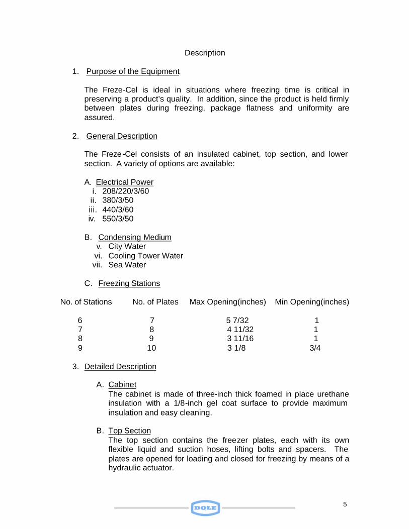
No. of Stations No. of Plates Max Opening(inches) Min Opening(inches) 6 7 5 7/32 1 7 8 4 11/32 1 8 9 3 11/16 1 9 10 3 1/8 3/4
3. Detailed Description
A. Cabinet The cabinet is made of three-inch thick foamed in place urethane insulation with a 1/8-inch gel coat surface to provide maximum insulation and easy cleaning.
B. Top Section
The top section contains the freezer plates, each with its own flexible liquid and suction hoses, lifting bolts and spacers. The plates are opened for loading and closed for freezing by means of a hydraulic actuator.
6
C. Lower Section The lower section houses the high side refrigeration and hydraulic systems. It includes a compressor, water-cooled condenser/receiver (5549 models), water-cooled condenser and separate receiver (on 6049 models), liquid sub-cooled heat exchanger, high side oil separator, low side oil separator, surge drum, liquid injector/distributor, oil float valve, hydraulic pump, and other accessories.
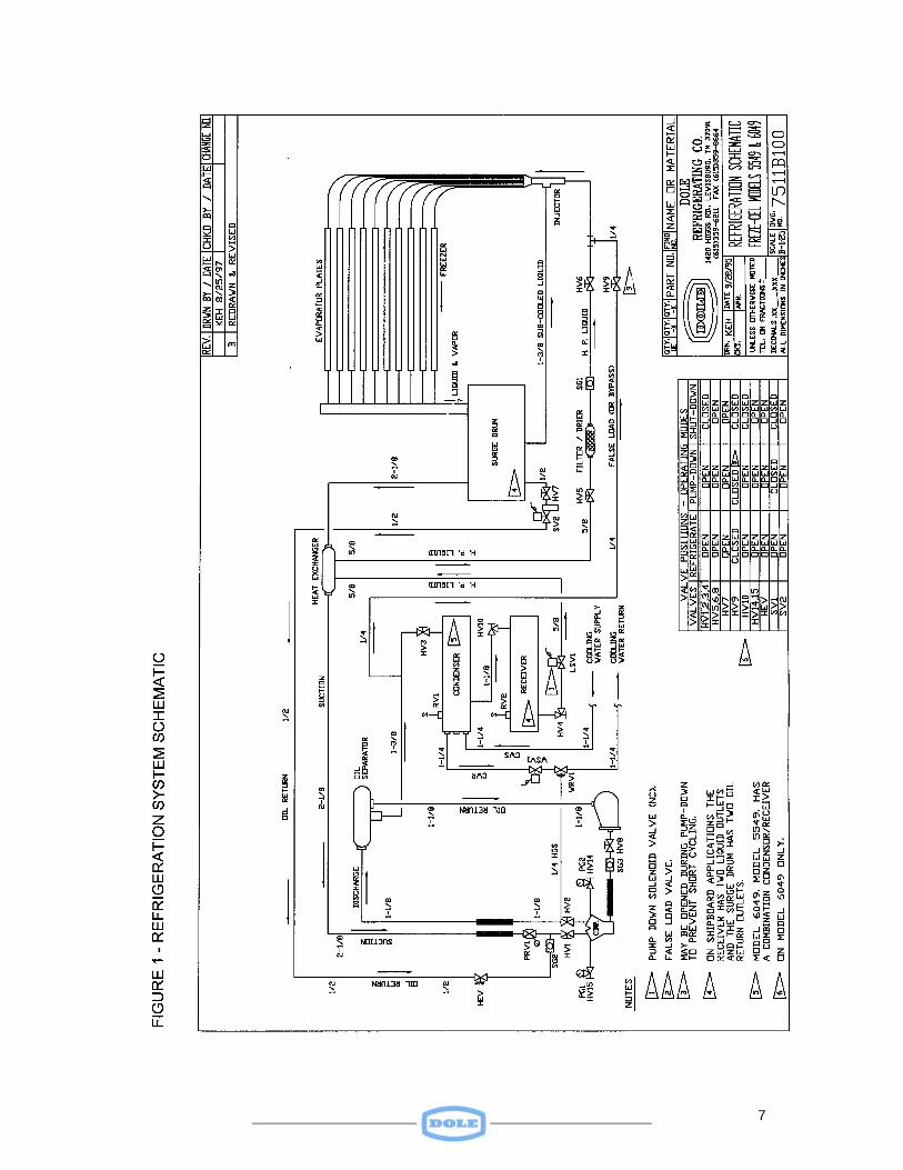
D. Refrigeration Cycle
Refrigerants offered in the Freze-Cel are R-502, R-404A and R-507. The refrigeration cycle is as follows: (Refer to Dole Drawing 7511-B100). The high-pressure liquid stored in the condenser flows through the filter/dryer, through the sub-cooling shell and tube heat exchanger, to the bottom of the injector distributor. In the injector, the refrigerant achieves a high velocity, which reduces its pressure and causes it to leave the nozzle in the jet stream. It enters the mixing throat of the injector and mixes with cold liquid refrigerant from the surge drum. The resulting sub cooled liquid is routed through the distributor to each freezer plate. A portion of the liquid vaporizes in the plates as a result of absorbing heat from the product. The compressor draws its suction from the top of the surge drum; liquid refrigerant in the drum is drawn into the injector where it mixes with the warmer liquid. The compressor discharge is routed through an oil separator to a water-cooled condenser (on Model 6049) or a condenser/receiver (on Model 5549).
E. Oil Return Systems
a. Low Side Oil Return:
Oil that makes its way into the surge drum exits the bottom of the drum and travels through the oil return solenoid valve (SV2), a pre-set hand expansion valve (HEV), a sight glass (SG2), and into the compressor suction line at the compressor. The oil return solenoid valve is a normally closed valve that is energized (opened) whenever the compressor is running and is de-energized (closed) whenever the compressor is not running.
b. High Side Oil Return:
A shell and tube oil separator is provided in the compressor discharge line to keep oil passing into the freezer plates to a minimum. Oil separated from the discharge gas is returned to the compressor crankcase via a float valve.
7
8
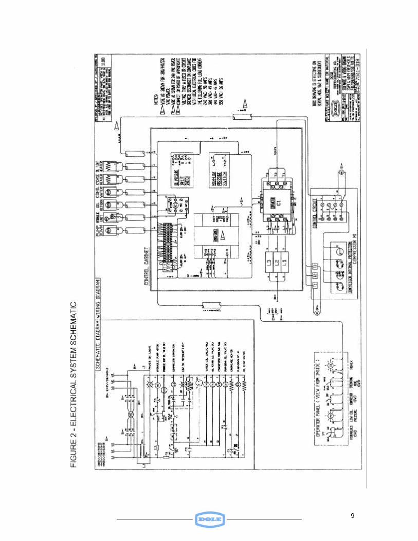
F. Electrical System
The freezer is factory wired. The installer must provide the proper power source to the system’s electrical control panel. In some areas voltage can vary to such an extent that damage to a compressor can result if built in compressor protection devices fail to react fast enough. A power line circuit breaker, installed in accordance with local codes, is recommended for such areas. For details of the electrical system refer to Figure 2.
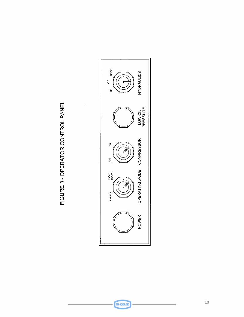
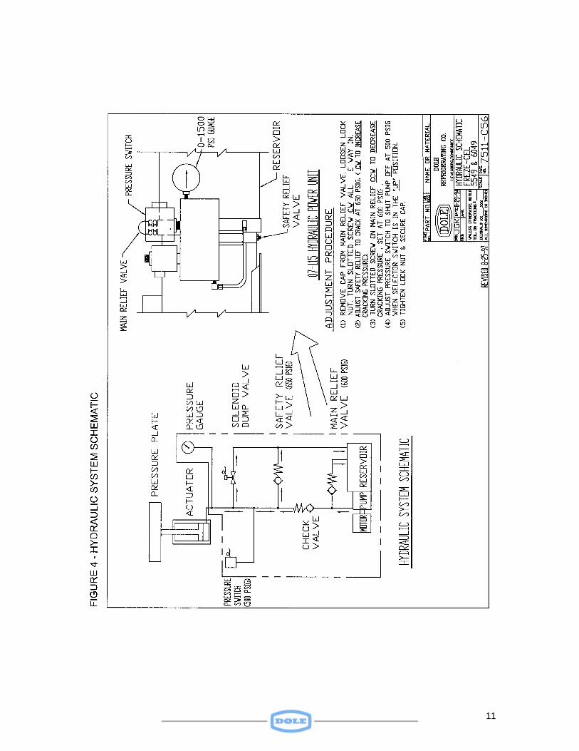
G. Hydraulic System
A “HYDRAULICS” switch on the operator control (Figure 3) panel provides a means of operating the hydraulic system. When the switch is in the “UP” position, the hydraulic pump motor is energized, producing the required hydraulic pressure to the actuator to raise the plates, closing them on the products. Hydraulic pressure increases until it reaches 600 psig, where the high- pressure control shuts the pump motor off. When products are frozen they tend to expand. This expansion can cause pressure locked in the actuator to increase. When this excess pressure reaches 650 psig, the system relief valve will prevent the pressure from exceeding this value while maintaining system pressure in the actuator. Internal leakage in the hydraulic system will cause the pressure to drop if the “HYDRAULICS” switch is in the “OFF” position. This will cause the plates to fall slowly, thereby losing one surface of contact with products. The system is designed to maintain pressure on the system to make up for such leakage as long as the “HYDRAULICS” switch is kept in the “UP” position. Therefore, it is recommended that the switch be kept in the “UP” position when the freezer is in operation. Placing the “HYDRAULICS” switch in the “DOWN” position energizes the solenoid dump valve, reducing pressure in the system. The plates will move downward due to gravity. To hold the plates in a given position, the switch would be placed in the “OFF” position. When the freezing cycle is complete, placing the switch in the “DOWN” position causes the plates to open up and permit unloading of the frozen product. Dexron II oil is used in the hydraulic system. For details of the hydraulic system refer to Figure 4.
9
10
11
12
Installation
1. Unpacking Freezer Remove wood crating, lumber skids and waterproof plastic cover. DO NOT REMOVE internal shipping and plate bracing until unit has been positioned and l eveled in its permanent location.
2. Locating Freezer
The floor on which the unit is to be installed should be capable of supporting a 250-psi load. Overall dimensions of the Freze-Cel are 86 inches high, 73-1/2 inches deep and 78 inches wide. By removing the cabinet doors, the freezer can pass through a 67-1/2 inch wide opening; by removing the freezer hardware, it will pass through a 64-inch opening. The freezer should be located to assure that at least one set of doors can be opened for loading and unloading products. The freezer can be operated in a pass thru fashion that permits loading through one set of doors and unloading products through the other set. Sufficient room should be provided on both sides of the freezer to permit the removal of a cabinet side to service hoses and on the other side for servicing the compressor, hydraulic pump, control units, filter/dryer, water regulating valve, solenoid valves, etc. Room should be provided for rodding the condenser. This space, a minimum of fifty (50) inches, may be on either side of the unit.
3. Leveling Freezer
Once the freezer is set in place, screw the four bolts provided into the nuts on the base skid, and level the unit. IMPORTANT: Freezer must be level for satisfactory performance. Once the freezer is leveled, shim or grout under the skid to prevent the unit from permanently resting on the leveling screws.
4. Connecting Utilities
A. Electrical Connection
The system power line and fused disconnect switch (supplied by the customer) should be installed in compliance with local, state, national or applicable shipboard electrical codes. Refer to Figure 2 for installation and servicing.
13
Connect power line (of proper size) to terminals L1, L2 and L3 and ground at top of terminal strip located in the electrical box within the machine compartment.
B. Recommended Fuse Capacities
230/3/60 Unit – Fusetron FRN 125 or Std. 200 Amp 380/3/50 Unit – Fusetron FRS 50 or Std. 70 Amp 440/3/60 Unit – Fusetron FRS 70 or Std. 100 Amp 550/3/50 Unit – Fusetron FRS 50 or Std. 70 Amp CAUTION: Do not operate compressor until electrical power has been supplied to the freezer for a period of at least four hours. The crankcase heater requires power for at least four hours to evaporate any liquid refrigerant that may have migrated there during shipment. Do not operate compressor before all five service valves (six on shipboard units) have been opened. Do not operate compressor before cooling water system has been connected and cooling water flow has been established.
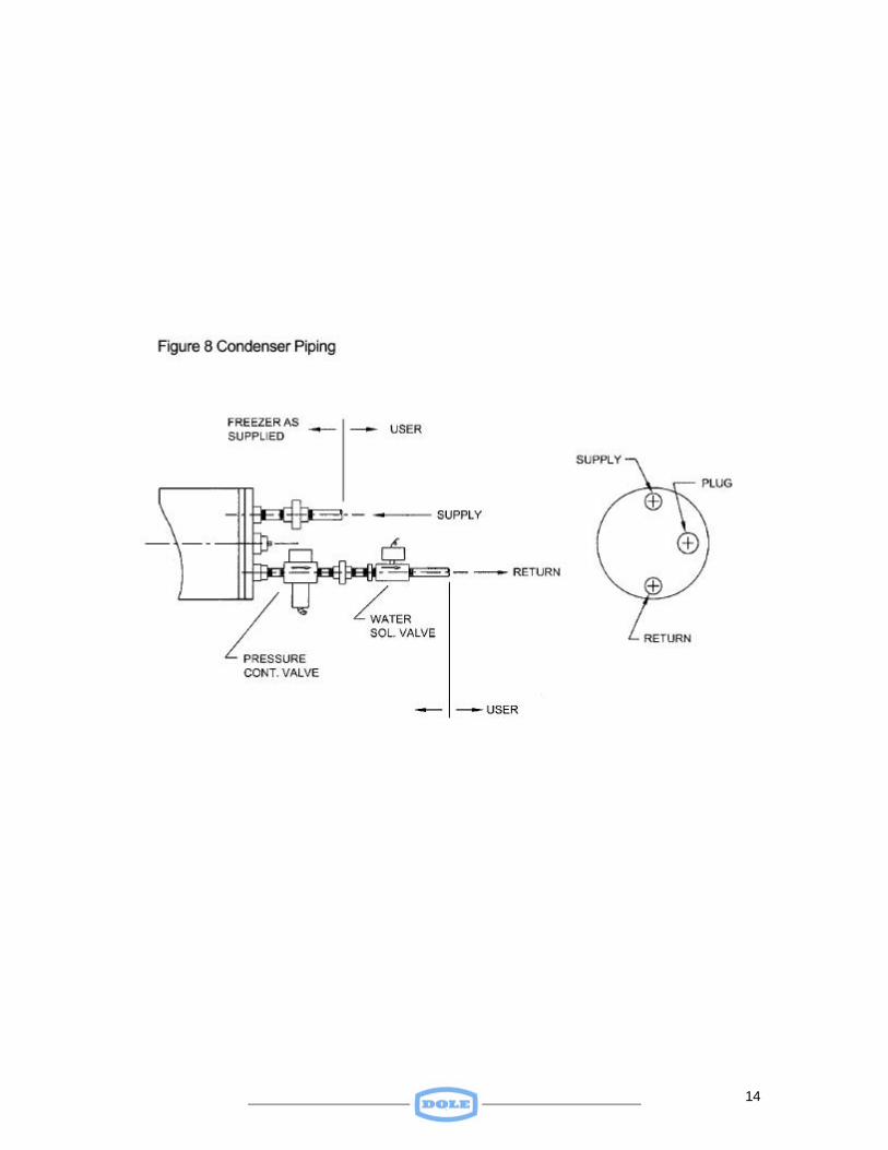
5. Water and Drain Connections
Connect 1 1/4 inch condenser water supply and return lines as shown in Figure 5. Connections should be made in compliance with applicable local, state, and national plumbing codes. When ambient temperature around the freezer is below 32-degree F. and the freezer is to be shut down for a period of time. The condenser and its associated water piping should be drained to prevent accumulation of ice inside the condenser that could damage the tubes.
14
15
Operating Instructions
1. General
Once water and electrical power have been connected, certain procedures should be followed to assure safe and efficient performance of the freezer.
2. Check of Electrical Power
DO NOT OPERATE THE COMPRESSOR UNTIL POWER HAS BEEN ON FOR AT LEAST FOUR HOURS. THIS WILL ASSURE THAT THE CRANKCASE HEATER WILL HAVE HAD TIME TO EVAPORATE ANY LIQUID REFRIGERANT, WHICH MAY HAVE MIGRATED INTO THE CRANKCASE DURING SHIPMENT.
3. Positioning of Service Valves
The freezer will have been shipped with all service valves closed. These valves must be opened prior to operating the compressor. See Figure 1 for valve position during the various operating modes.
4. Operator Control Panel
Figure 3 shows the layout of indicator lights and switches on the Operator Control Panel. When lit the green “POWER” light indicates the presence of power in the unit. The red “LOW OIL PRESSURE” light, when lit, indicates insufficient oil pressure available for proper compressor lubrication. It can indicate lack of oil or a pump failure. The “OPERATING MODE” switch permits the freezer to be pumped down after use, or when the freezer is to be out of service for several days. This switch should be placed in the “FREEZE” position during a freezing cycle. The “HYDRAULICS” switch provides a means of opening (“DOWN”) the plates to permit product loading and unloading. It permits a means of closing (“UP”) the plates for freezing. With the switch in the “OFF” position the plates can be held in a specific position, anywhere between fully open and fully closed.
5. Refrigeration Mode
With the system’s power on (green “POWER” light lit) and the “Operating Mode” switch in the “Freeze” position, the compressor should operate with refrigerant flowing freely through the plates. The “COMPRESSOR” switch should be in the “ON” position at all times except when the freezer is to be out of service for more than a week. If
16
the “COMPRESSOR” switch has been in the “OFF” position for more than a day, observe the following:
CAUTION: Do not operate the compressor until electrical power has been supplied to the freezer for a period of at least FOUR hours. The crankcase heater requires power for at least four hours to evaporate any liquid refrigerant that may have migrated since the unit had been shut down. Do not operate the compressor before all five service valves (six on shipboard models) have been opened. Do not operate compressor before the cooling water has been connected and turned on to the condenser. The “OPERATING MODE” switch, which will be in the “FREEZE” position during the refrigerating mode, should be placed in the “PUMP DOWN” position if it is desired to pump down the system after, or between, freezing cycles. Placing the switch in the “PUMP DOWN” position results in the closing of the liquid solenoid valve (LSV1), thereby preventing liquid from flowing to the plates. With the “OPERATING MODE” switch in the “PUMP DOWN” position, the compressor will cycle between the preset cutout/cut in suction pressures.
6. Product Loading
The freezer should be ready for product loading one hour after compressor startup. The “HYDRAULICS” switch should be placed in the “DOWN” position to increase the space between plates. Product packages or trays may then be placed in the freezer. The product should be loaded uniformly on each plate. DO NOT partially load a plate. For most effective freezing, all stations should be loaded with product. If a station(s) is to be empty during freezing due to the lack of enough product to fill all stations, the empty station(s) should be located ABOVE all stations loaded with product. For efficient freezing, plates should be kept free of frost.
7. Liquid Refrigerant Level
Check the liquid level in the surge drum AFTER THE COMPRESSOR HAS BEEN IN OPERATION FOR TWO HOURS. The liquid level should stabilize at the centerline of the sight glass.
17
DO NOT add refrigerant unless sight glass indicates in undercharge condition after running the compressor for at least two hours.
8. Crankcase Oil Level
After the compressor has been in operation for at least two hours check the compressor crankcase oil level. The oil level in the crankcase oil sight glass should stabilize at the center of the sight glass, with compressor operating. After initial inspection of crankcase oil level, check level at least once a week.
9. Setting Water Regulating Valve
The water-regulating valve will have been factory preset to 210-psig-compressor discharge pressure and for best operating efficiency should be maintained at that level. To increase compressor discharge pressure, adjust the valve counter clockwise. This will decrease cooling water flow and cause the compressor discharge pressure to rise. To decrease compressor discharge pressure adjust the valve clockwise. This will increase the water flow and cause the compressor discharge pressure to fall.
COMPRESSOR DISCHARGE SHOULD NOT BE ALLOWED TO RISE ABOVE 250 PSIG OR TO DECREASE BELOW 150 PSIG.
10. Miscellaneous
For efficient freezing, plates should be kept free of frost. When the freezer is not in use the doors should be left open to aid in defrosting plate surfaces. Different thickness of product may be frozen simultaneously in separate stations. This is not an efficient method of freezing since thicker packages take longer to freeze than thinner ones and production freezing rates will be lower than would be the case if all packages were the same thickness.
18
Maintenance
General
This section provides instructions on preventive maintenance, refrigerant charging, liquid pumpdown and compressor oil charging procedures.
1. General Maintenance
Once a day during the normal operating cycle, with the COMPRESSOR RUNNING, the refrigerant level in the surge drum sight glass should be checked. A liquid level consistently above the 3/4-point of the sight glass indicates a refrigerant overcharge. Excess refrigerant should be pumped out and reclaimed. A liquid level consistently below the center of the surge drum sight glass indicates a refrigerant undercharge condition and possible a refrigerant leak. Door panel hinges should be adjusted to reduce any door sag by tightening the hinge mounting screws. Door panel gaskets should be check regularly. Hinges and the door latch should be adjusted if necessary to affect a proper seal. If the tendency for a gasket is to freeze, apply Dow Corning Slipicone or other suitable gasket dressing to the gasket surface.
2. Crankcase Oil Level
At least once a week, the crankcase oil level in the crankcase sight glass should be checked WITH THE COMPRESSOR RUNNING. An oil level below the center of the crankcase sight glass indicates that the compressor is low on oil.
3. Oil Pressure Safety Control
In the event the oil pressure safety control shuts the compressor down, the compressor switch on the operator control panel should be placed in the “OFF” position. The oil return solenoid valve (SV2) should be closed when the compressor is not running and should be open whenever the compressor is running. If no defective component is found, charge the proper amount of oil to the crankcase. DO NOT reset the safety control before adding oil.
4. Liquid Pumpdown Procedure
If a freezer is to be shut off for a period of more than two days, or if the unit is to be replaced, the following pumpdown procedure should be followed:
19
a. If the freezer has just completed a freezing cycle, turn off the compressor by positioning the “COMPRESSOR” switch to “OFF”. Let the unit sit overnight with the doors open and the MAIN POWER SWITCH on. This will insure that the crankcase heater remains energized to prevent refrigerant migration to the crankcase.
b. Close the liquid outlet valve (HV4) at the bottom of the receiver.
c. Connect a gage manifold to the back-seated suction valve
(HV1) and discharge valve (HV2) charging ports. Then close both valves one turn.
d. Start the compressor and jumper 9 to 10 (“L”& “M”) on the High-
Low Pressure Switch (see Figure 2) to keep the compressor running. When the suction pressure gage indicates and 8 to 10-inch vacuum, turn the compressor off by positioning the “COMPRESSOR” switch to “OFF”.
e. Close the pumpdown shutoff valve by placing the “OPERATING
MODE” switch in the “PUMPDOWN ” position. Close the oil return valve (HV8), suction valve (HV1), and discharge valves (HV2 and HV3).
5. Crankcase Oil Charging Procedure If the oil level in the crankcase falls below the center of the sight glass and no defective parts are found in the oil return system, additional oil should be added to the crankcase. The following steps should be taken: A. Close the oil return hand valve (HV8)
B. Close the compressor suction (HV1). The compressor suction pressure should be +1 or –1 psig. C. Close the compressor discharge valve (HV2). D. Unscrew the hex plug from the brass cross on the front of the compressor. Pump oil into the crankcase until the oil level reaches 3/4 of the sight glass. Copeland Ultra 22 Polyester Lubricant, Synthetic Refrigeration Oil is used from the factory.
6. Charging Procedure After Leak Repair
A. Connect a refrigerant charging hose to the gage manifold charging port. Crack the refrigerant drum gas valve to purge the hose, and then
20
tighten the gage manifold to the compressor suction valve (HV1) gage port.
B. Close the compressor suction valve (HV1) one turn.
C. Open the refrigerant drum gas valve and charge the proper amount of
the “gaseous” refrigerant into the system while the compressor is running until the liquid level shown on the surge drum sight glass reaches the center of the sight glass.
DO NOT OVERCHARGE THE SYSTEM!
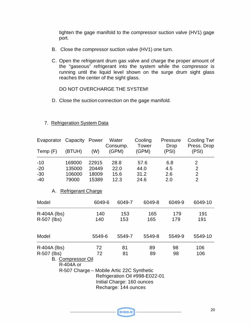
D. Close the suction connection on the gage manifold. 7. Refrigeration System Data
Evaporator Capacity Power Water Cooling Pressure Cooling Twr Consump. Tower Drop Press. Drop Temp (F) (BTUH) (W) (GPM) (GPM) (PSI) (PSI)
-10 169000 22915 28.8 57.6 6.8 2 -20 135000 20449 22.0 44.0 4.5 2 -30 106000 18009 15.6 31.2 2.6 2 -40 79000 15389 12.3 24.6 2.0 2
A. Refrigerant Charge
Model 6049-6 6049-7 6049-8 6049-9 6049-10
R-404A (lbs) 140 153 165 179 191 R-507 (lbs) 140 153 165 179 191 Model 5549-6 5549-7 5549-8 5549-9 5549-10
R-404A (lbs) 72 81 89 98 106 R-507 (lbs) 72 81 89 98 106
B. Compressor Oil R-404A or R-507 Charge – Mobile Artic 22C Synthetic Refrigeration Oil #998-E022-01 Initial Charge: 160 ounces Recharge: 144 ounces
21
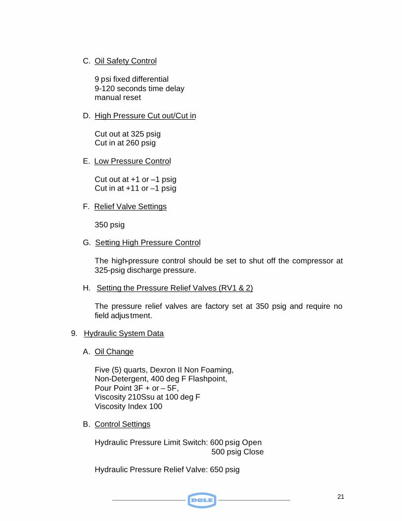
C. Oil Safety Control
9 psi fixed differential 9-120 seconds time delay manual reset
D. High Pressure Cut out/Cut in
Cut out at 325 psig Cut in at 260 psig
E. Low Pressure Control
Cut out at +1 or –1 psig Cut in at +11 or –1 psig
F. Relief Valve Settings
350 psig
G. Setting High Pressure Control
The high-pressure control should be set to shut off the compressor at 325-psig discharge pressure.
H. Setting the Pressure Relief Valves (RV1 & 2)
The pressure relief valves are factory set at 350 psig and require no field adjus tment.
9. Hydraulic System Data
A. Oil Change
Five (5) quarts, Dexron II Non Foaming, Non-Detergent, 400 deg F Flashpoint, Pour Point 3F + or – 5F, Viscosity 210Ssu at 100 deg F Viscosity Index 100
B. Control Settings
Hydraulic Pressure Limit Switch: 600 psig Open 500 psig Close Hydraulic Pressure Relief Valve: 650 psig
22
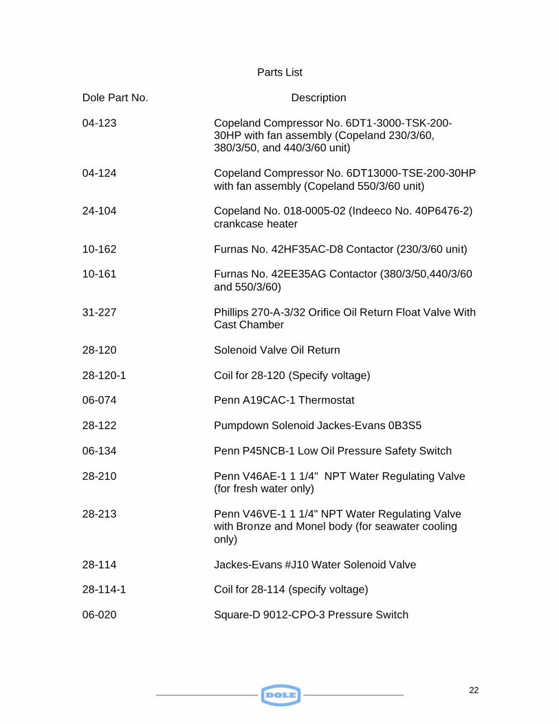
Parts List
Dole Part No. Description 04-123 Copeland Compressor No. 6DT1-3000-TSK-200-
30HP with fan assembly (Copeland 230/3/60, 380/3/50, and 440/3/60 unit)
04-124 Copeland Compressor No. 6DT13000-TSE-200-30HP
with fan assembly (Copeland 550/3/60 unit) 24-104 Copeland No. 018-0005-02 (Indeeco No. 40P6476-2)
crankcase heater 10-162 Furnas No. 42HF35AC-D8 Contactor (230/3/60 unit) 10-161 Furnas No. 42EE35AG Contactor (380/3/50,440/3/60
and 550/3/60) 31-227 Phillips 270-A-3/32 Orifice Oil Return Float Valve With
Cast Chamber 28-120 Solenoid Valve Oil Return 28-120-1 Coil for 28-120 (Specify voltage) 06-074 Penn A19CAC-1 Thermostat 28-122 Pumpdown Solenoid Jackes-Evans 0B3S5 06-134 Penn P45NCB-1 Low Oil Pressure Safety Switch 28-210 Penn V46AE-1 1 1/4" NPT Water Regulating Valve
(for fresh water only) 28-213 Penn V46VE-1 1 1/4" NPT Water Regulating Valve
with Bronze and Monel body (for seawater cooling only)
28-114 Jackes-Evans #J10 Water Solenoid Valve 28-114-1 Coil for 28-114 (specify voltage) 06-020 Square-D 9012-CPO-3 Pressure Switch
23
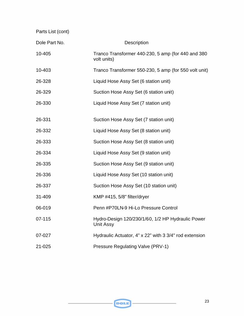
Parts List (cont) Dole Part No. Description 10-405 Tranco Transformer 440-230, 5 amp (for 440 and 380
volt units) 10-403 Tranco Transformer 550-230, 5 amp (for 550 volt unit) 26-328 Liquid Hose Assy Set (6 station unit) 26-329 Suction Hose Assy Set (6 station unit) 26-330 Liquid Hose Assy Set (7 station unit) 26-331 Suction Hose Assy Set (7 station unit) 26-332 Liquid Hose Assy Set (8 station unit) 26-333 Suction Hose Assy Set (8 station unit) 26-334 Liquid Hose Assy Set (9 station unit) 26-335 Suction Hose Assy Set (9 station unit) 26-336 Liquid Hose Assy Set (10 station unit) 26-337 Suction Hose Assy Set (10 station unit) 31-409 KMP #415, 5/8” filter/dryer 06-019 Penn #P70LN-9 Hi-Lo Pressure Control 07-115 Hydro-Design 120/230/1/60, 1/2 HP Hydraulic Power
Unit Assy 07-027 Hydraulic Actuator, 4” x 22” with 3 3/4" rod extension 21-025 Pressure Regulating Valve (PRV-1)
24
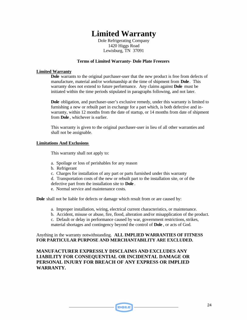
Limited Warranty Dole Refrigerating Company
1420 Higgs Road Lewisburg, TN 37091
Terms of Limited Warranty- Dole Plate Freezers
Limited Warranty
Dole warrants to the original purchaser-user that the new product is free from defects of manufacture, material and/or workmanship at the time of shipment from Dole . This warranty does not extend to future performance. Any claims against Dole must be initiated within the time periods stipulated in paragraphs following, and not later. Dole obligation, and purchaser-user’s exclusive remedy, under this warranty is limited to furnishing a new or rebuilt part in exchange for a part which, is both defective and in-warranty, within 12 months from the date of startup, or 14 months from date of shipment from Dole , whichever is earlier. This warranty is given to the original purchaser-user in lieu of all other warranties and shall not be assignable.
Limitations And Exclusions This warranty shall not apply to: a. Spoilage or loss of perishables for any reason b. Refrigerant c. Charges for installation of any part or parts furnished under this warranty
d. Transportation costs of the new or rebuilt part to the installation site, or of the defective part from the installation site to Dole . e. Normal service and maintenance costs.
Dole shall not be liable for defects or damage which result from or are caused by: a. Improper installation, wiring, electrical current characteristics, or maintenance.
b. Accident, misuse or abuse, fire, flood, alteration and/or misapplication of the product. c. Default or delay in performance caused by war, government restrictions, strikes, material shortages and contingency beyond the control of Dole , or acts of God.
Anything in the warranty notwithstanding. ALL IMPLIED WARRANTIES OF FITNESS FOR PARTICULAR PURPOSE AND MERCHANTABILITY ARE EXCLUDED. MANUFACTURER EXPRESSLY DISCLAIMS AND EXCLUDES ANY LIABILITY FOR CONSEQUENTIAL OR INCIDENTAL DAMAGE OR PERSONAL INJURY FOR BREACH OF ANY EXPRESS OR IMPLIED WARRANTY.