ece r41, r51 - jasic...ece r41, r51 noise on motorcycles and passenger cars general information...
TRANSCRIPT
ECE R41, R51ECE R41, R51NOISE on motorcycles and passenger carsNOISE on motorcycles and passenger cars
Y. ShirahashiS. Yonezawa
JASIC Noise-sub committee
ECE R41, R51ECE R41, R51NOISE on motorcycles and passenger carsNOISE on motorcycles and passenger cars
General informationGeneral information
Yoshihiro Shirahashi
JASIC Noise Subcommittee
ContentsContents1. WP29 and GRB
2. Common Information on R41/R511)1) Vehicle categoriesVehicle categories
2)2) HistoriesHistories
3)3) Application Application
4)4) ApprovalApproval
5)5) MarkingMarking
6)6) COPCOP
7)7) PenaltiesPenalties
The United NationThe United Nation’’s Organizations Organization
Noise
UN
ECE
GRPEGREGRBGRB GRRF GRSPGRSG
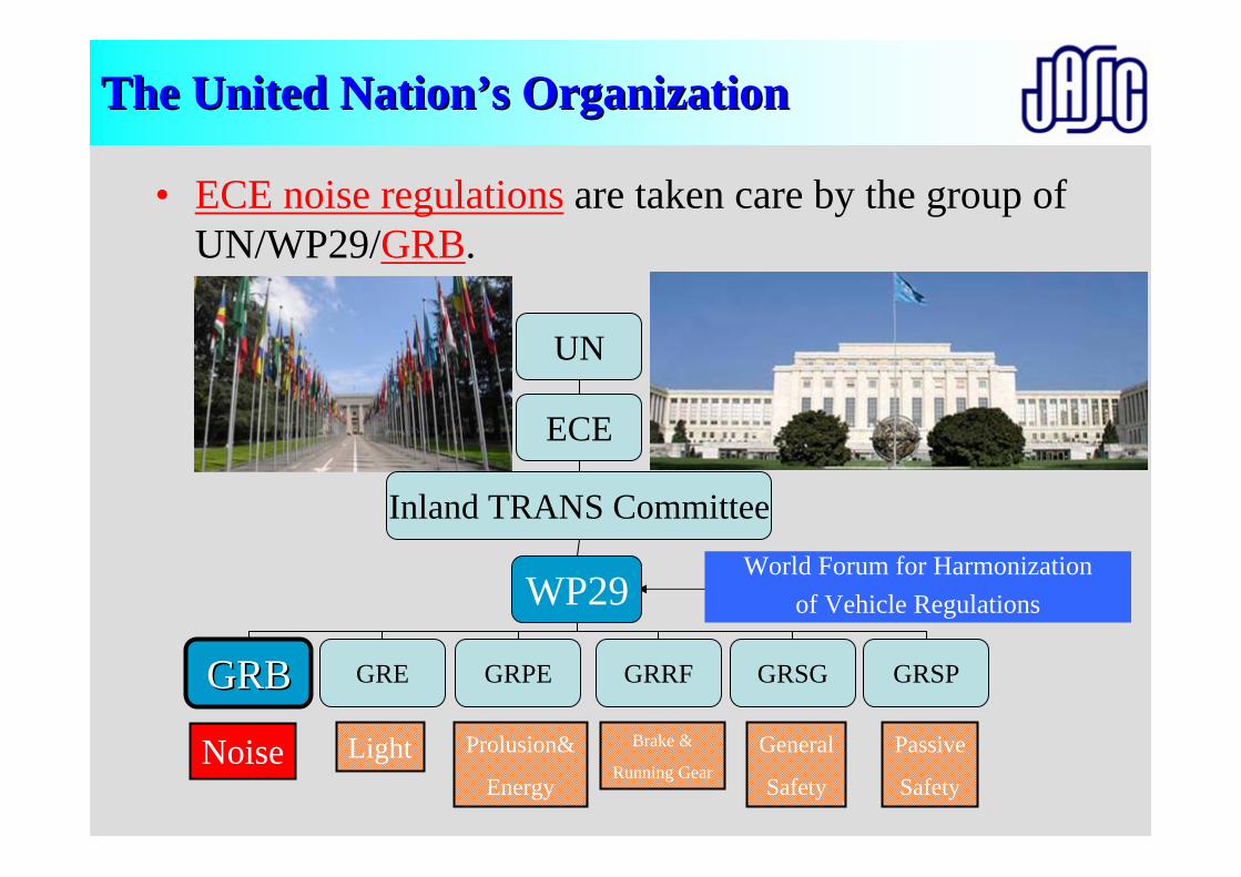
• ECE noise regulations are taken care by the group of UN/WP29/GRB.
Light Prolusion&
Energy
Brake &
Running GearGeneral
Safety
Passive
Safety
Inland TRANS Committee
WP29World Forum for Harmonization
of Vehicle Regulations
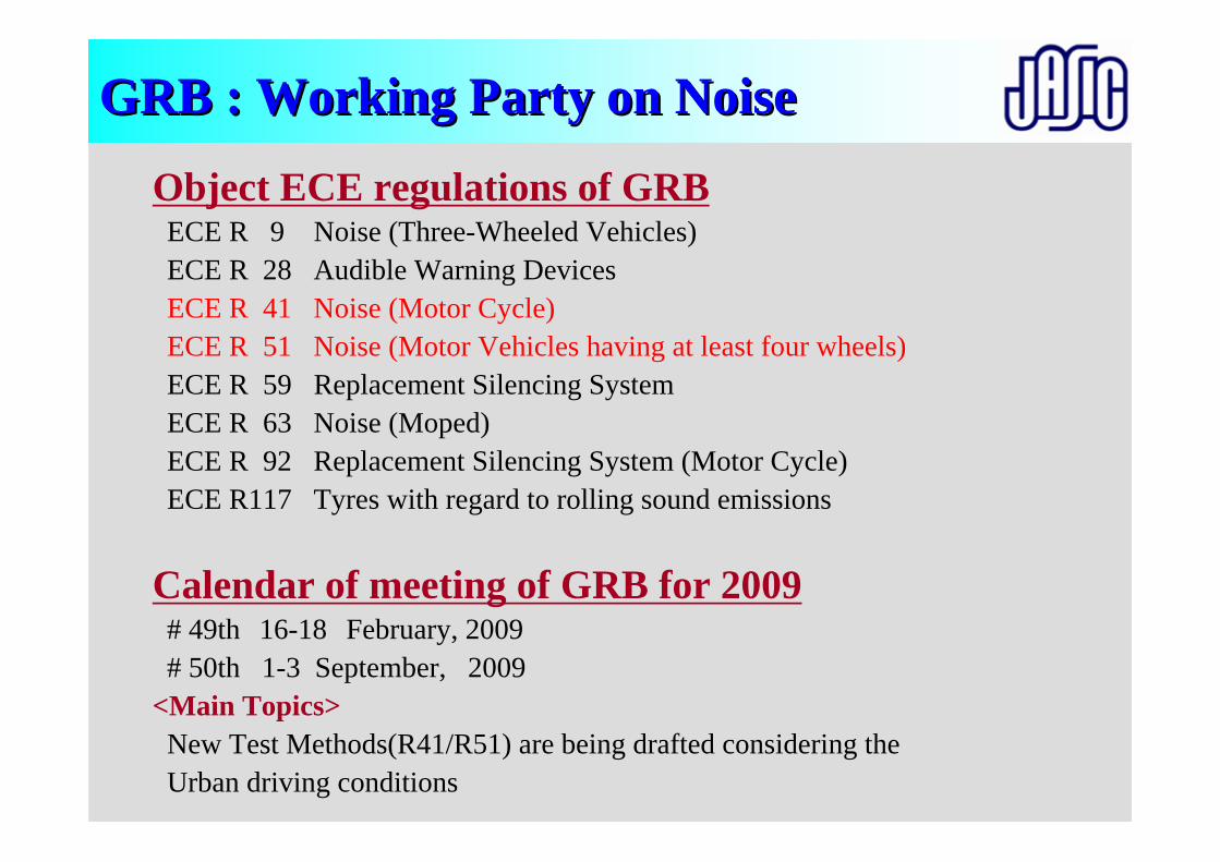
Object ECE regulations of GRBECE R 9 Noise (Three-Wheeled Vehicles)ECE R 28 Audible Warning DevicesECE R 41 Noise (Motor Cycle)ECE R 51 Noise (Motor Vehicles having at least four wheels)ECE R 59 Replacement Silencing SystemECE R 63 Noise (Moped)ECE R 92 Replacement Silencing System (Motor Cycle)ECE R117 Tyres with regard to rolling sound emissions
Calendar of meeting of GRB for 2009# 49th 16-18 February, 2009# 50th 1-3 September, 2009
<Main Topics>New Test Methods(R41/R51) are being drafted considering the Urban driving conditions
GRB : Working Party on NoiseGRB : Working Party on Noise
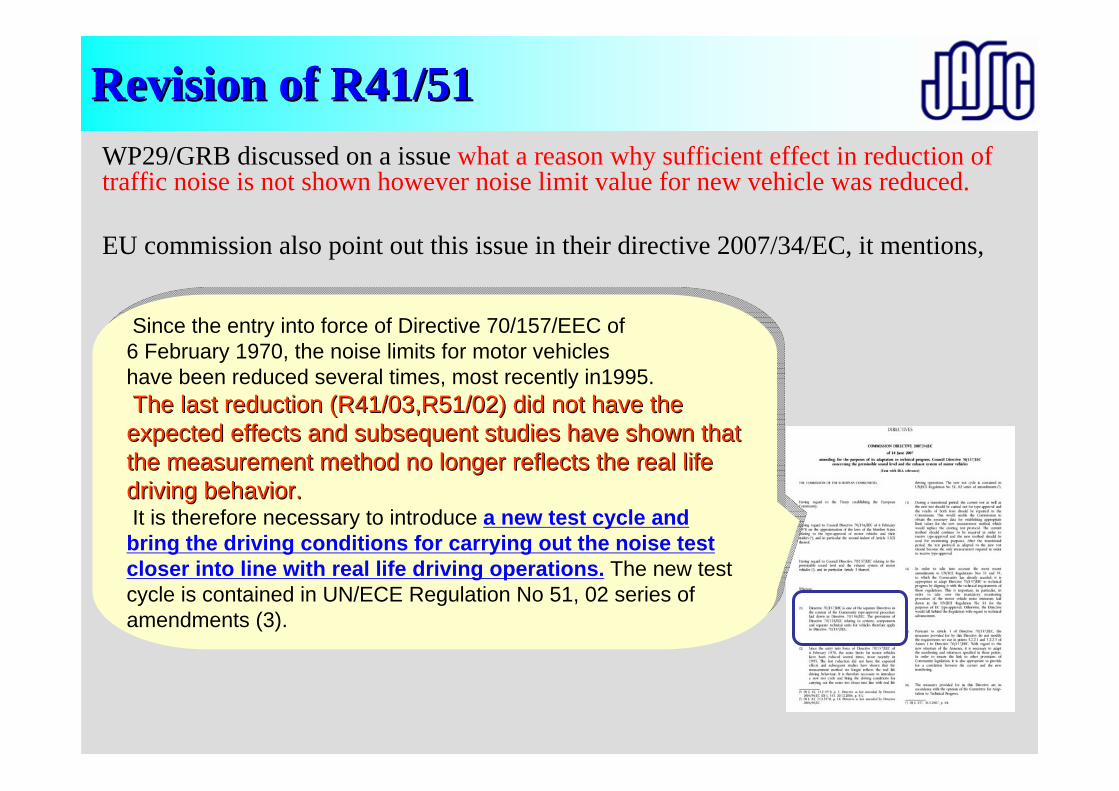
Revision of R41/51 Revision of R41/51 WP29/GRB discussed on a issue what a reason why sufficient effect in reduction of traffic noise is not shown however noise limit value for new vehicle was reduced.
EU commission also point out this issue in their directive 2007/34/EC, it mentions,
Since the entry into force of Directive 70/157/EEC of6 February 1970, the noise limits for motor vehicleshave been reduced several times, most recently in1995.The last reduction (R41/03,R51/02) did not have the expected effects and subsequent studies have shown that the measurement method no longer reflects the real life driving behavior.It is therefore necessary to introduce a new test cycle and
bring the driving conditions for carrying out the noise test closer into line with real life driving operations. The new test cycle is contained in UN/ECE Regulation No 51, 02 series of amendments (3).
Since the entry into force of Directive 70/157/EEC of6 February 1970, the noise limits for motor vehicleshave been reduced several times, most recently in1995.The last reduction (R41/03,R51/02) did not have the The last reduction (R41/03,R51/02) did not have the expected effects and subsequent studies have shown that expected effects and subsequent studies have shown that the measurement method no longer reflects the real life the measurement method no longer reflects the real life driving behavior.driving behavior.It is therefore necessary to introduce a new test cycle and
bring the driving conditions for carrying out the noise test closer into line with real life driving operations. The new test cycle is contained in UN/ECE Regulation No 51, 02 series of amendments (3).
15% 25% 35% 45% 55% 65% 75% 85%
100%
90%
80%
70%
60%
50%
40%
30%
20%
10%
0%
Engine Speed Normalized
Engine
Pow
er Normalized
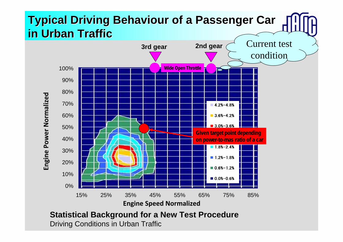
Typical Driving Behaviour of a Passenger Car Typical Driving Behaviour of a Passenger Car in Urban Trafficin Urban Traffic
Statistical Background for a New Test ProcedureDriving Conditions in Urban Traffic
Wide Open Throttle
2nd gear Current test condition
3rd gear
Given target point depending on power-to-mas ratio of a car
[FINAL DRAFT]ECONOMIC COMMISSION FOR EUROPE INLAND TRANSPORT COMMITTEE
World Forum for Harmonization of Vehicle Regulations (WP.29)(One-hundred-and-thirty-eighth session, 7-10 March 2006, agenda item 4.2.11.)
PROPOSAL FOR SUPPLEMENT 4 TO THE 02 SERIES OF AMENDMENTS TO REGULATION No. 51(Noise emissions)
Transmitted by the representative of the European Community (EC)
Note: The text reproduced below was prepared by the representative of the EC with a view to introduce anadditional test method for noise of motor vehicles which is intended to reproduce the noise levels generatedby vehicles during normal driving in urban traffic.This document is an alternative proposal to ECE/TRANS/WP.29/2006/4.This document is a working document circulated for discussion and comments. The use of this document for other purposes is the entire responsibility of the user.Documents are also available via the INTERNET: http://www.unece.org/trans/main/welcwp29.htmThe list of Contents,
Annex 3, amended to read:“Annex 3 - Methods and instruments for measuring the noise made by motor vehicles
(Measurement Method A)Insert new Annexes 9 and 10, to read:
"Annex 9 - Vehicle Test Data persuant to Measurement Method BAnnex 10 - Methods and instruments for measuring the noise made by motor vehicles
(Measurement Method B)“
ContentsContents1. WP29 and GRB
2. Common Information on R41/R511)1) Vehicle categoriesVehicle categories
2)2) HistoriesHistories
3)3) Application Application
4)4) ApprovalApproval
5)5) MarkingMarking
6)6) COPCOP
7)7) PenaltiesPenalties
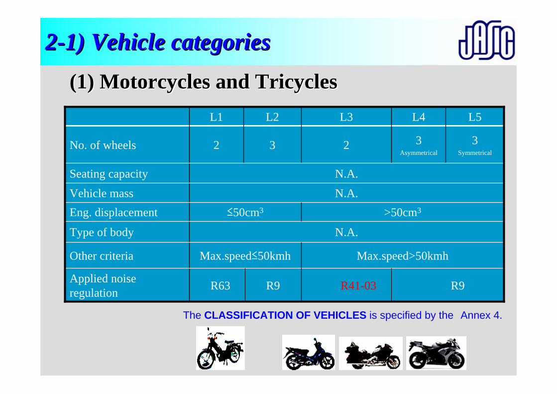
R41-03 R9R63 R9Applied noise regulation
Max.speed>50kmhMax.speed≤50kmhOther criteria
N.A.Type of body
>50cm3≤50cm3Eng. displacementN.A.Vehicle mass
N.A.Seating capacity
3Symmetrical
L5
3Asymmetrical
L4
2
L3
3
L2
2
L1
No. of wheels
22--1) Vehicle categories1) Vehicle categories
(1) Motorcycles and Tricycles(1) Motorcycles and Tricycles
The CLASSIFICATION OF VEHICLES is specified by the Annex 4.
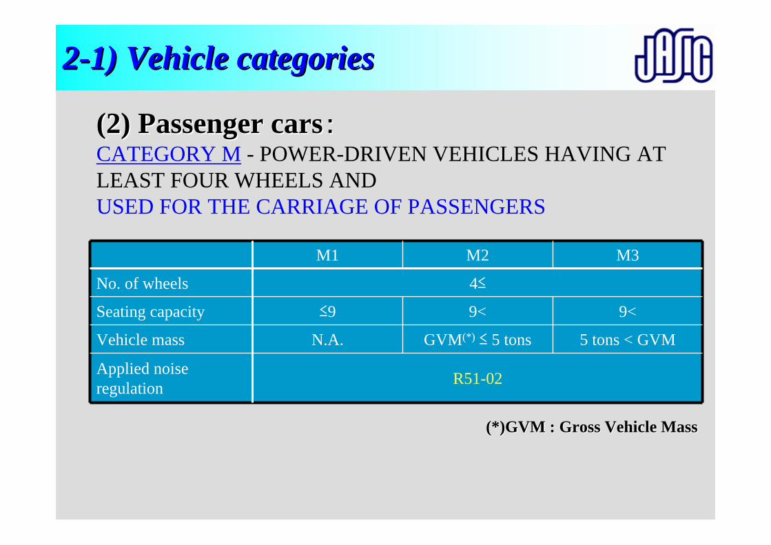
22--1) Vehicle categories1) Vehicle categories
5 tons < GVM
9<
GVM(*) ≤ 5 tons
9<
R51-02Applied noise regulation
N.A.Vehicle mass
≤9Seating capacity
M3M2
4≤
M1
No. of wheels
(2) Passenger cars(2) Passenger cars::CATEGORY M - POWER-DRIVEN VEHICLES HAVING AT LEAST FOUR WHEELS ANDUSED FOR THE CARRIAGE OF PASSENGERS
(*)GVM : Gross Vehicle Mass(*)GVM : Gross Vehicle Mass
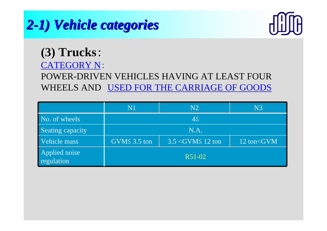
22--1) Vehicle categories1) Vehicle categories
3.5 <GVM≤ 12 ton 12 ton<GVM
R51-02Applied noise regulation
GVM≤ 3.5 tonVehicle massN.A.Seating capacity
N3N24≤
N1No. of wheels
(3) Trucks(3) Trucks::CATEGORY N:POWER-DRIVEN VEHICLES HAVING AT LEAST FOUR WHEELS AND USED FOR THE CARRIAGE OF GOODS
22--2) Histories2) Histories
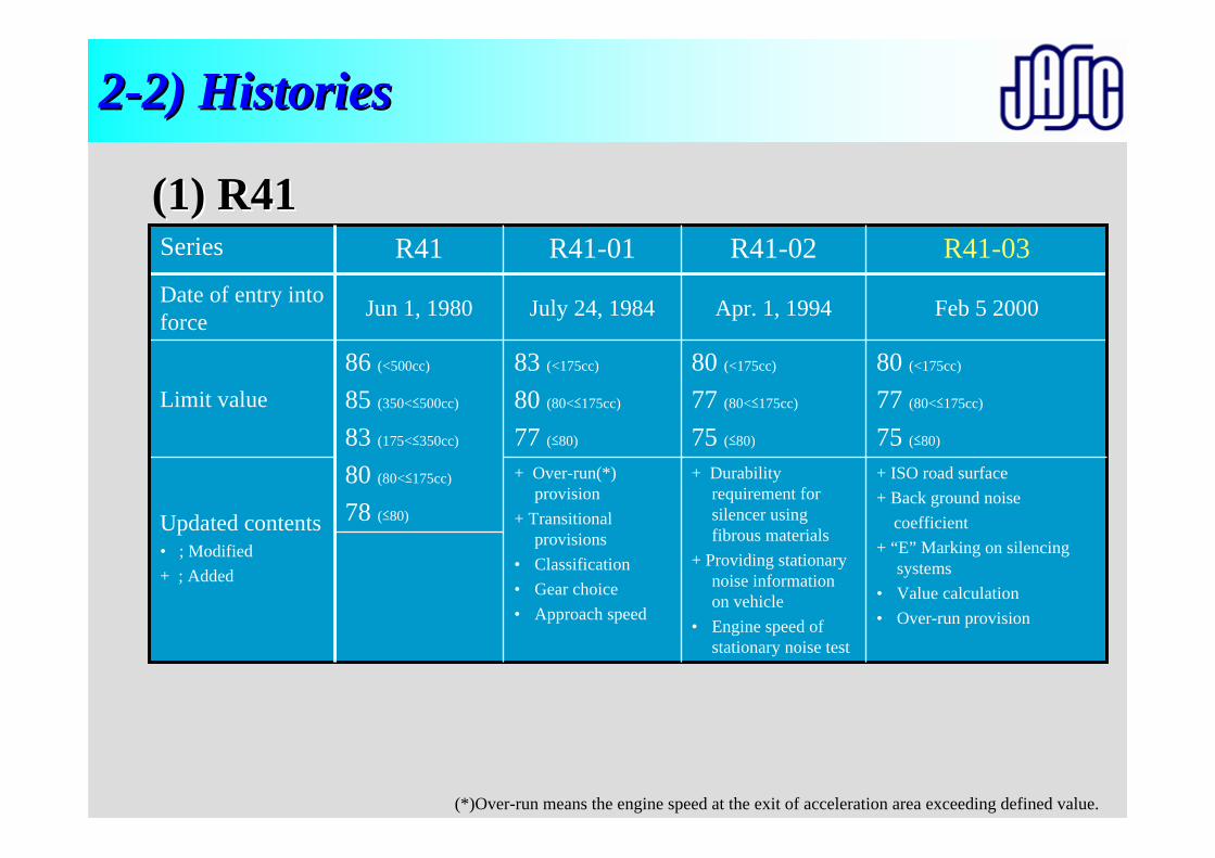
+ Over-run(*) provision
+ Transitional provisions
• Classification• Gear choice• Approach speed
83 (<175cc)
80 (80<≤175cc)
77 (≤80)
July 24, 1984
R41-01
+ ISO road surface+ Back ground noise
coefficient+ “E” Marking on silencing
systems• Value calculation• Over-run provision
+ Durability requirement for silencer using fibrous materials
+ Providing stationary noise information on vehicle
• Engine speed of stationary noise test
Updated contents• ; Modified+ ; Added
80 (<175cc)
77 (80<≤175cc)
75 (≤80)
80 (<175cc)
77 (80<≤175cc)
75 (≤80)
86 (<500cc)
85 (350<≤500cc)
83 (175<≤350cc)
80 (80<≤175cc)
78 (≤80)
Limit value
Feb 5 2000Apr. 1, 1994Jun 1, 1980Date of entry into force
R41-03R41-02R41Series
(*)Over-run means the engine speed at the exit of acceleration area exceeding defined value.
(1) R41(1) R41
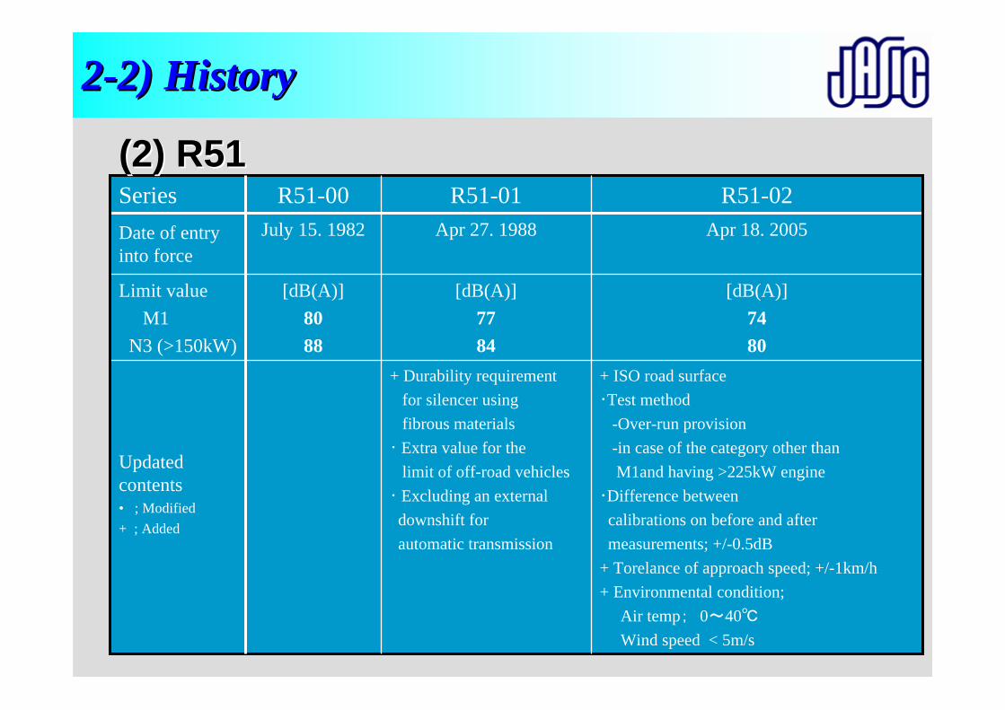
22--2) History2) History
+ ISO road surface・Test method
-Over-run provision-in case of the category other thanM1and having >225kW engine
・Difference between calibrations on before and after measurements; +/-0.5dB
+ Torelance of approach speed; +/-1km/h+ Environmental condition;
Air temp; 0~40℃
Wind speed < 5m/s
+ Durability requirement for silencer using fibrous materials
・ Extra value for the limit of off-road vehicles
・ Excluding an external downshift for automatic transmission
Updated contents• ; Modified+ ; Added
[dB(A)]7480
[dB(A)]7784
[dB(A)]8088
Limit value M1
N3 (>150kW)
Apr 18. 2005 Apr 27. 1988 July 15. 1982 Date of entry into force
R51-02R51-01R51-00Series(2) R51(2) R51
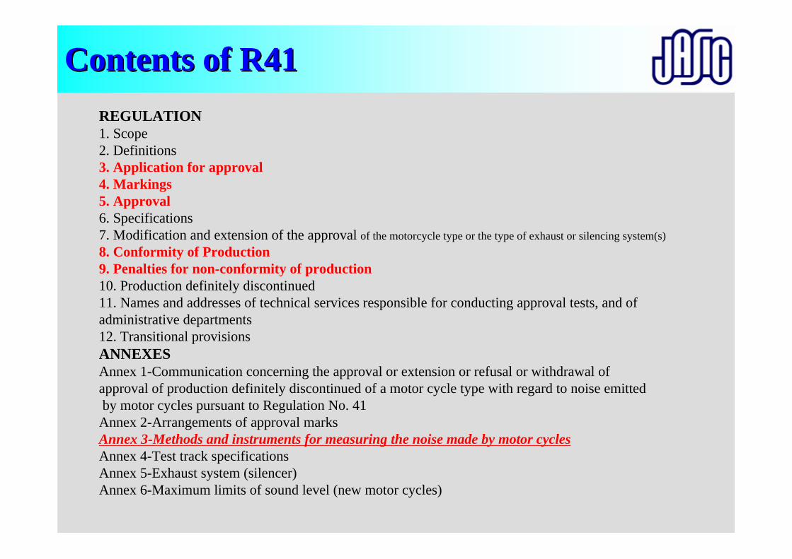
REGULATION1. Scope2. Definitions3. Application for approval4. Markings5. Approval6. Specifications7. Modification and extension of the approval of the motorcycle type or the type of exhaust or silencing system(s)8. Conformity of Production9. Penalties for non-conformity of production10. Production definitely discontinued11. Names and addresses of technical services responsible for conducting approval tests, and ofadministrative departments12. Transitional provisionsANNEXESAnnex 1-Communication concerning the approval or extension or refusal or withdrawal of approval of production definitely discontinued of a motor cycle type with regard to noise emittedby motor cycles pursuant to Regulation No. 41
Annex 2-Arrangements of approval marksAnnex 3-Methods and instruments for measuring the noise made by motor cyclesAnnex 4-Test track specificationsAnnex 5-Exhaust system (silencer)Annex 6-Maximum limits of sound level (new motor cycles)
Contents of R41Contents of R41
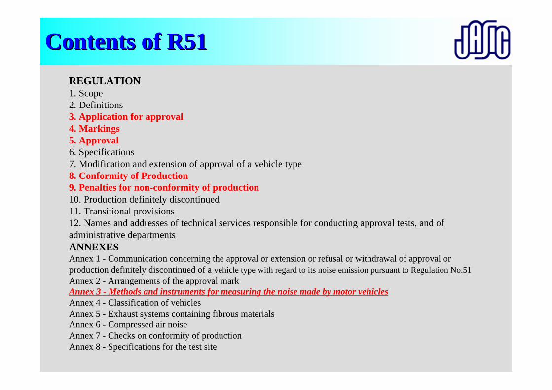
Contents of R51Contents of R51REGULATION1. Scope2. Definitions3. Application for approval4. Markings5. Approval6. Specifications7. Modification and extension of approval of a vehicle type8. Conformity of Production9. Penalties for non-conformity of production10. Production definitely discontinued11. Transitional provisions12. Names and addresses of technical services responsible for conducting approval tests, and ofadministrative departmentsANNEXESAnnex 1 - Communication concerning the approval or extension or refusal or withdrawal of approval orproduction definitely discontinued of a vehicle type with regard to its noise emission pursuant to Regulation No.51 Annex 2 - Arrangements of the approval markAnnex 3 - Methods and instruments for measuring the noise made by motor vehiclesAnnex 4 - Classification of vehiclesAnnex 5 - Exhaust systems containing fibrous materialsAnnex 6 - Compressed air noiseAnnex 7 - Checks on conformity of productionAnnex 8 - Specifications for the test site

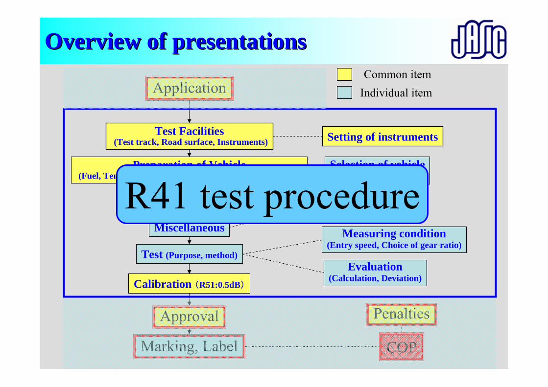
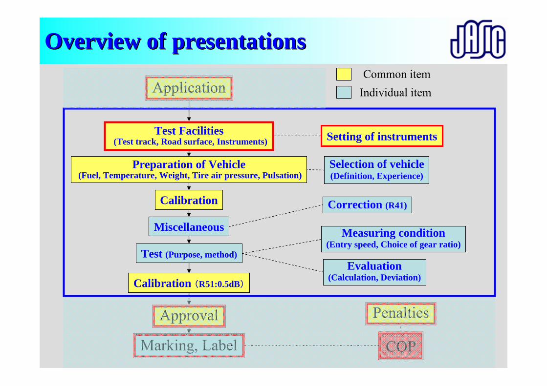
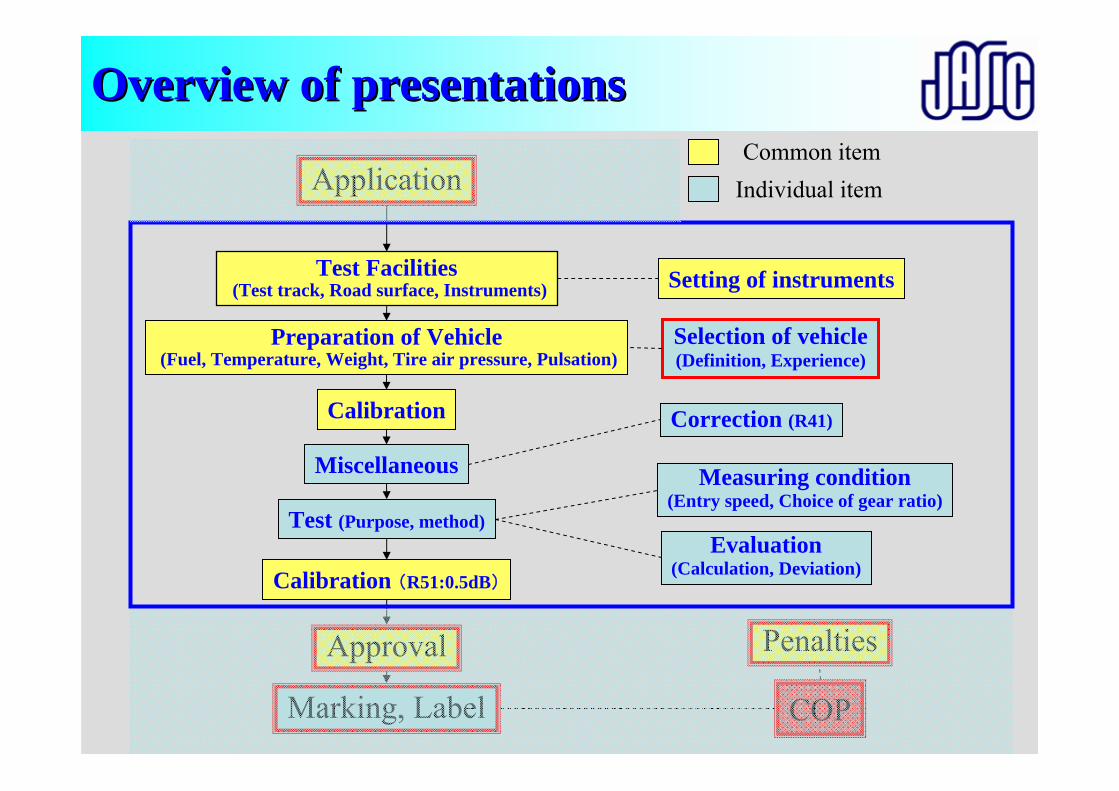
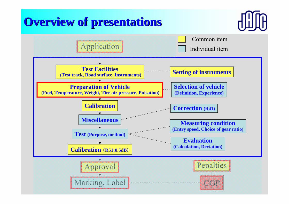
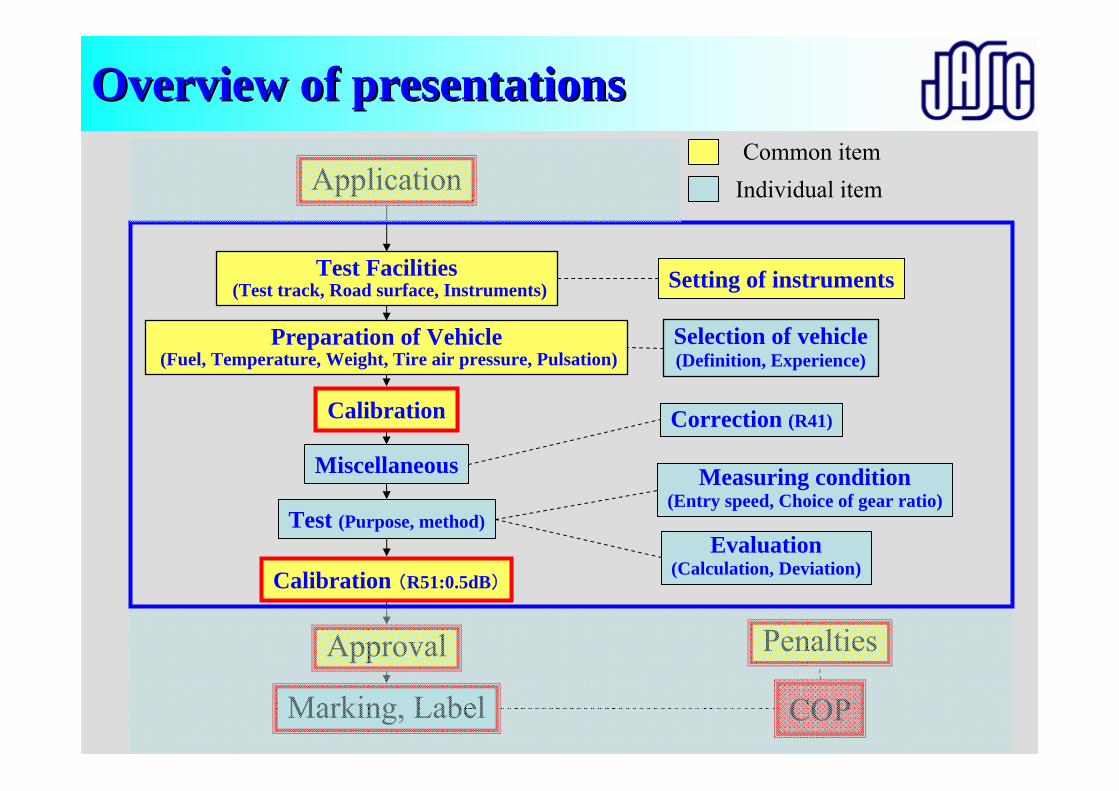
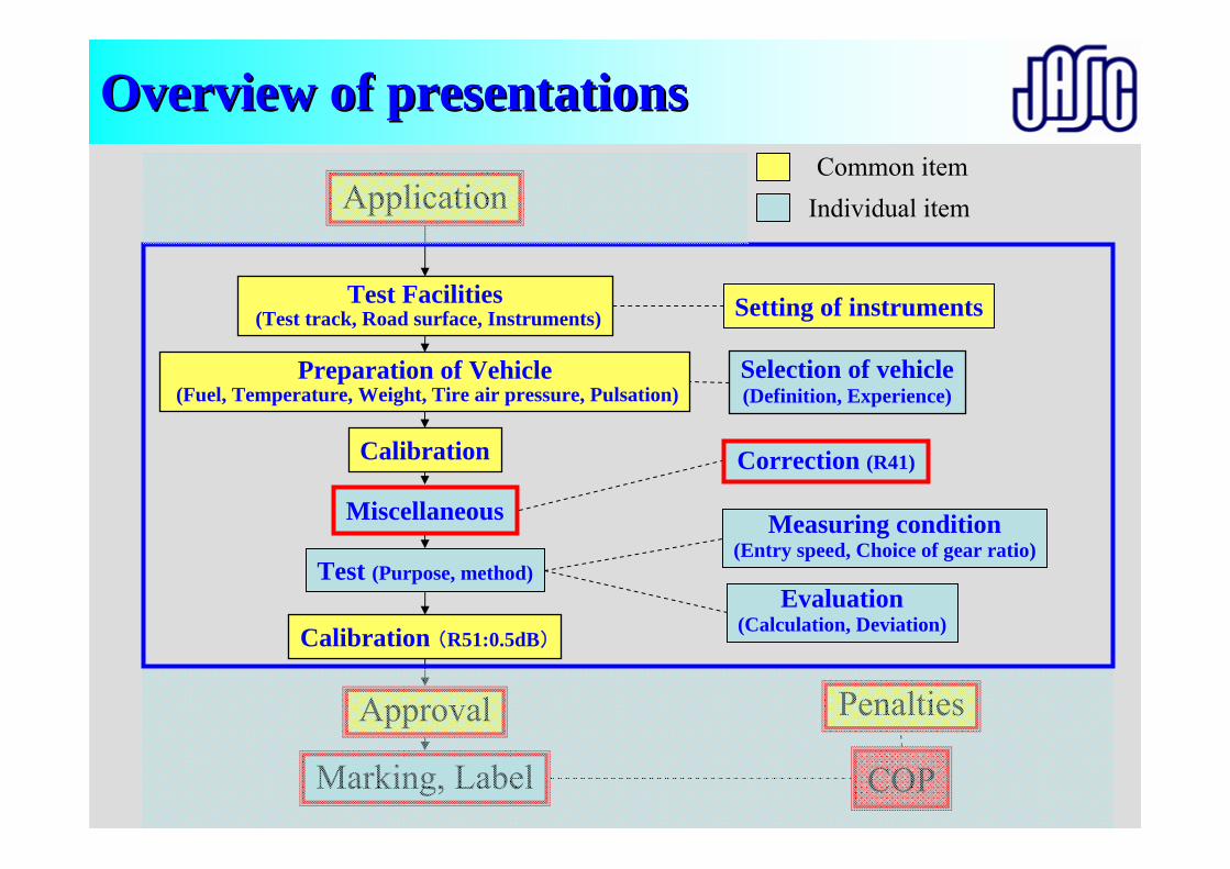
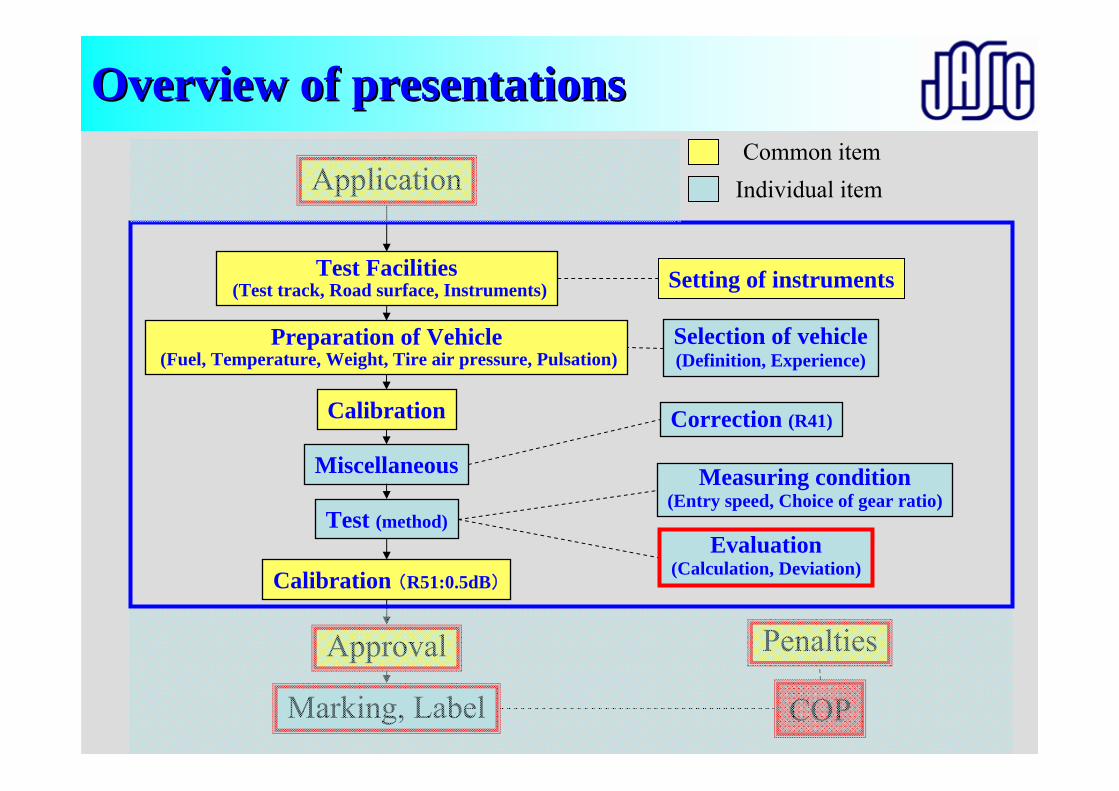
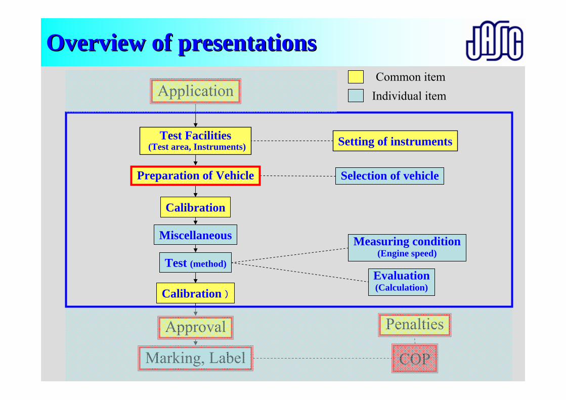
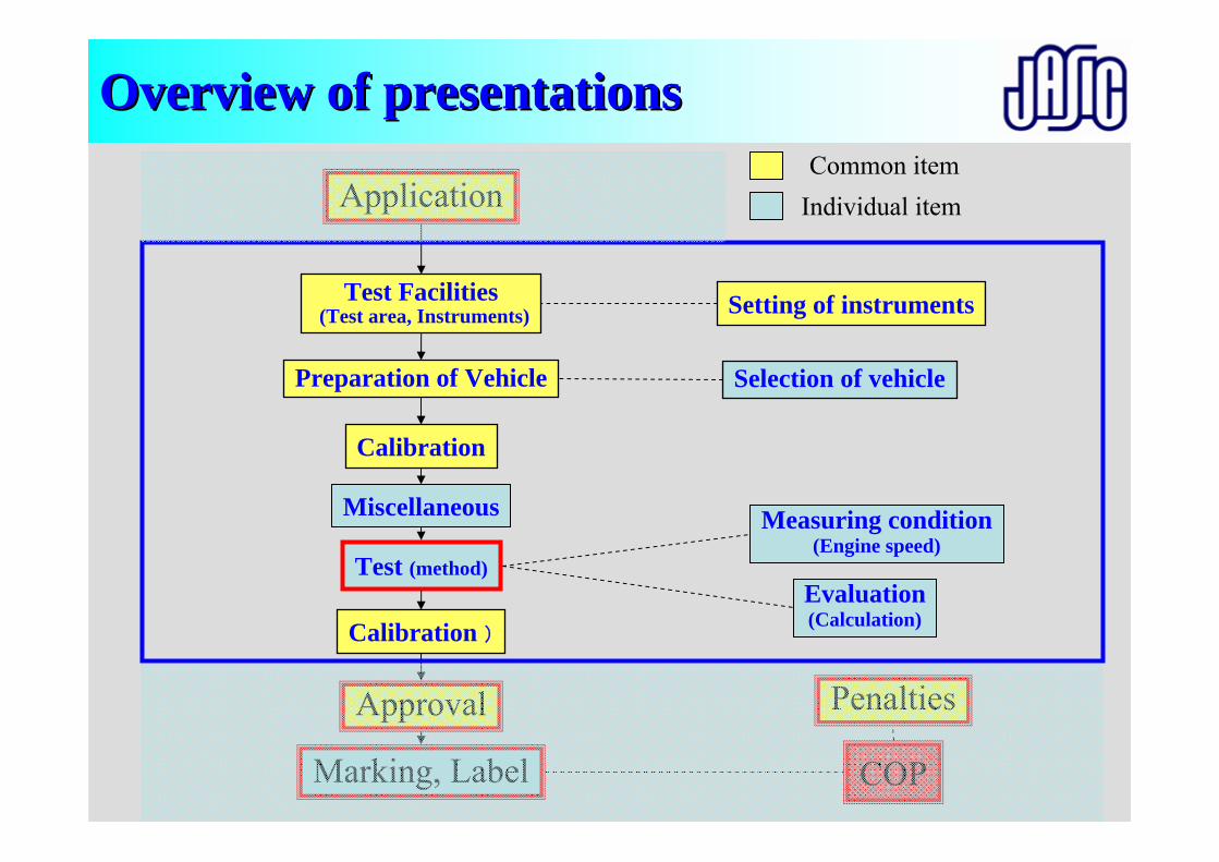
Preparation of Vehicle(Fuel, Temperature, Weight, Tire air pressure, Pulsation)
Test Facilities(Test track, Road surface, Instruments)
Miscellaneous
Calibration
Test (Purpose, method)
Calibration (R51:0.5dB)
Selection of vehicle(Definition, Experience)
Correction (R41)
Evaluation(Calculation, Deviation)
Measuring condition(Entry speed, Choice of gear ratio)
Setting of instruments
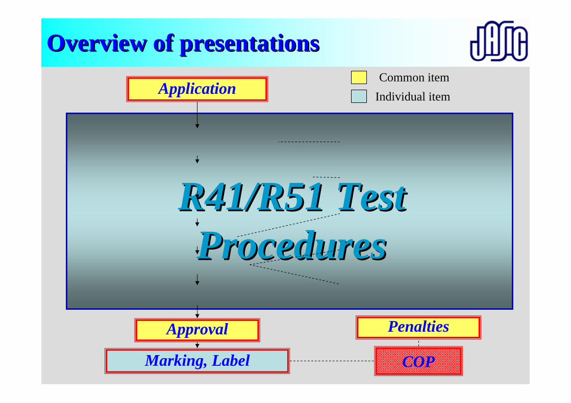
Approval
Marking, Label COP
Application Common item
Individual item
Penalties
R41/R51 Test R41/R51 Test ProceduresProcedures
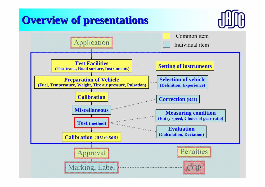
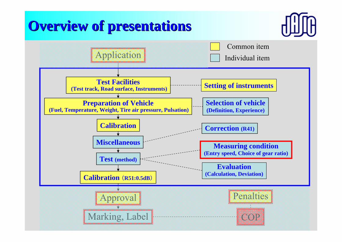
Overview of presentationsOverview of presentations
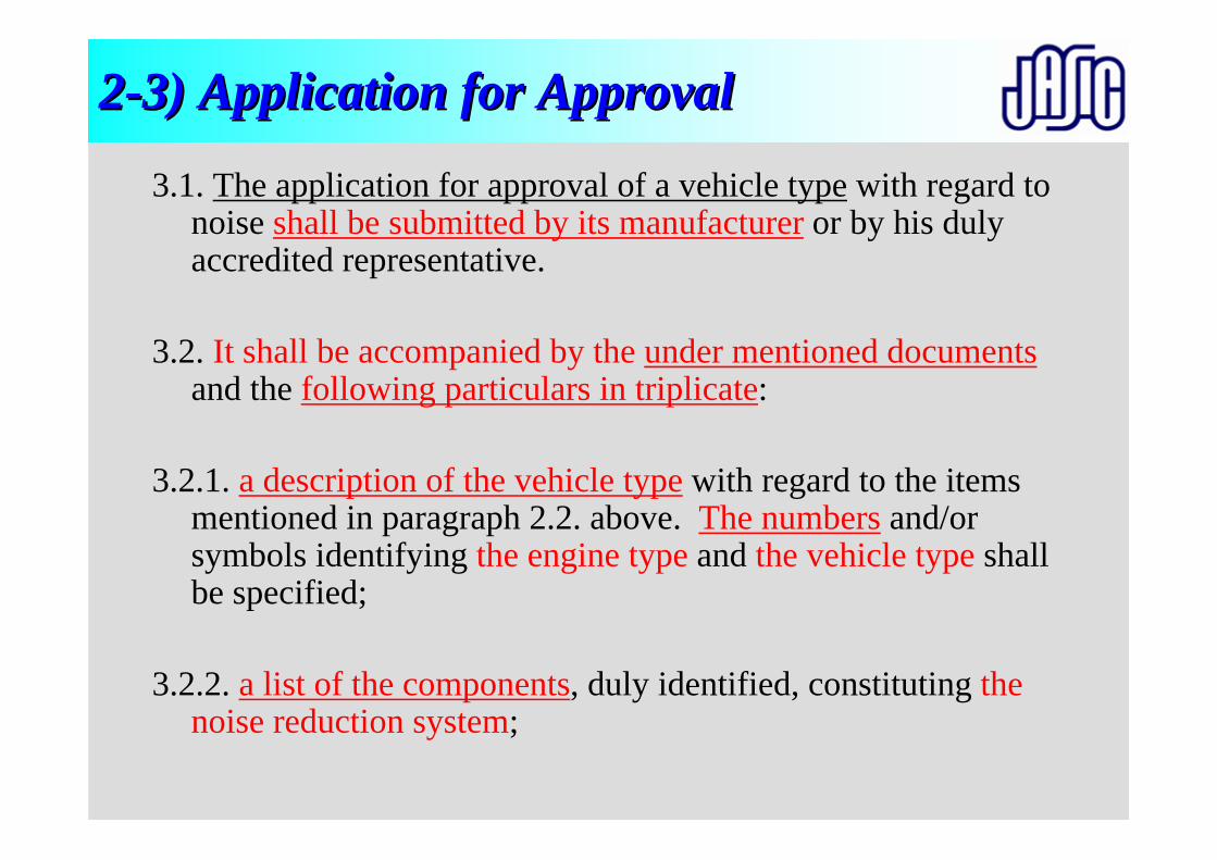
22--3) Application for Approval3) Application for Approval
3.1. The application for approval of a vehicle type with regard to noise shall be submitted by its manufacturer or by his duly accredited representative.
3.2. It shall be accompanied by the under mentioned documentsand the following particulars in triplicate:
3.2.1. a description of the vehicle type with regard to the items mentioned in paragraph 2.2. above. The numbers and/or symbols identifying the engine type and the vehicle type shall be specified;
3.2.2. a list of the components, duly identified, constituting the noise reduction system;
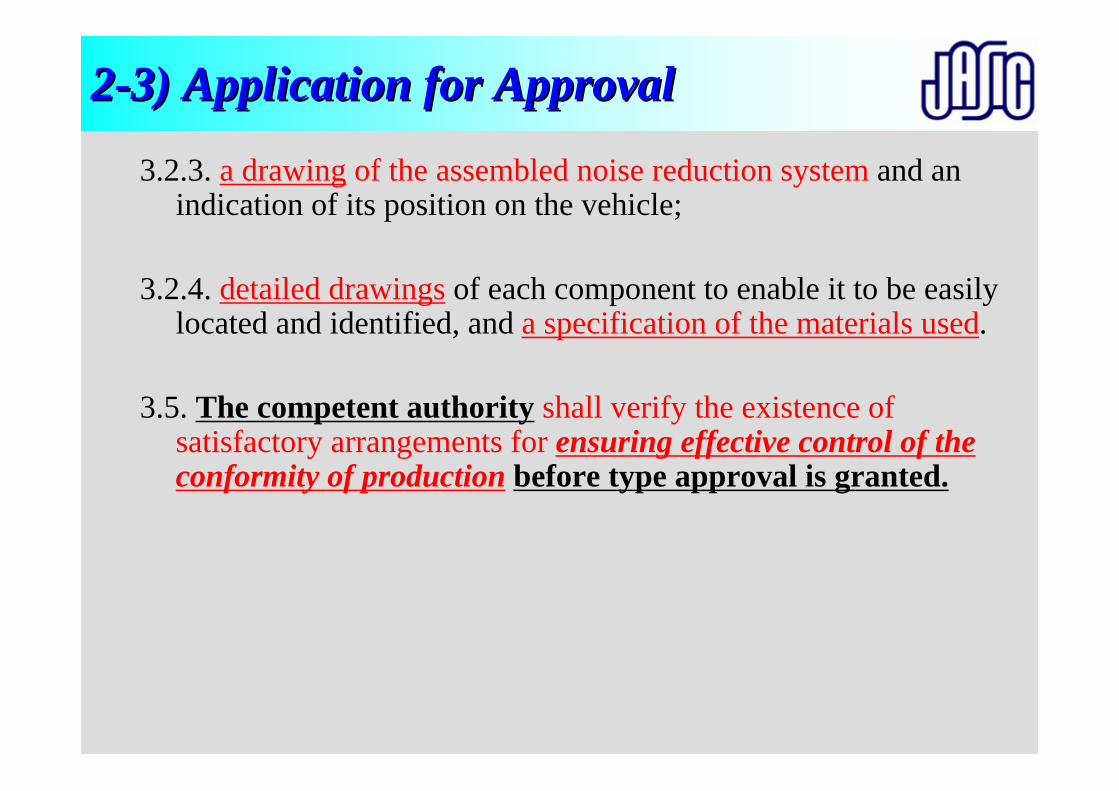
22--3) Application for Approval3) Application for Approval
3.2.3. a drawing of the assembled noise reduction system and an indication of its position on the vehicle;
3.2.4. detailed drawings of each component to enable it to be easily located and identified, and a specification of the materials used.
3.5. The competent authority shall verify the existence of satisfactory arrangements for ensuring effective control of the conformity of production before type approval is granted.
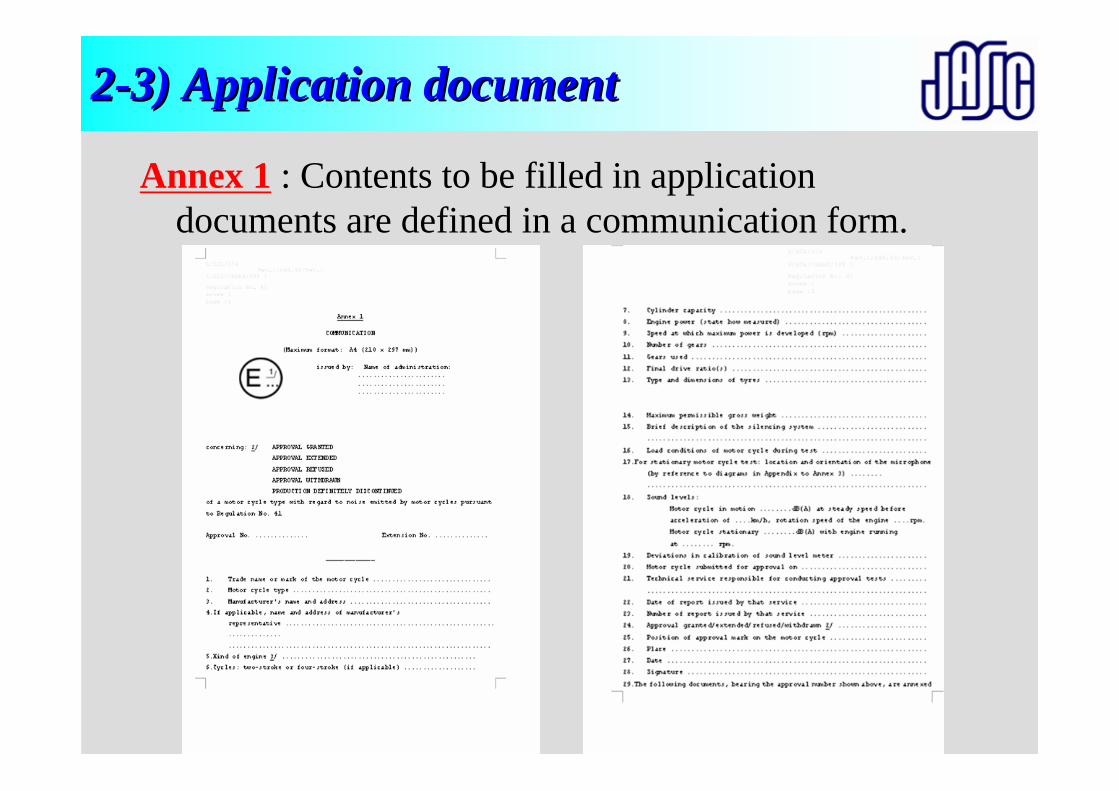
22--3) Application document3) Application document
Annex 1 : Contents to be filled in application documents are defined in a communication form.
22--3) Application document3) Application document
General information• Trade name or mark of the vehicle• Vehicle Type• Name and address of vehicle manufacturer• Engine Type• Engine model• Name and address of engine manufacturer
22--3) Application document (cont3) Application document (cont’’d)d)
Vehicle information• Maximum permissible mass• Transmission type• Number of gears• Final drive ratio (For motorcycle)
Engine information• Rated maximum engine power• Kind of engine• Cycles• Cylinder capacity
22--3) Application document (cont3) Application document (cont’’d)d)
Equipments information>Exhaust silencer:Manufacturer, Model, Type: in accordance with drawing No.>Intake silencerManufacturer, Model, Type: in accordance with drawing No.>Type and dimensions of tires
Diagrams and plans of>The engine and the noise reduction systemPhotographs>The engine and the noise reduction system>List of components constituting the noise reduction system.
Intake system
Exhaust system
MufflerExhaust noise
Muffler diffusion noise
Intake diffusion noise
Intake suction noise
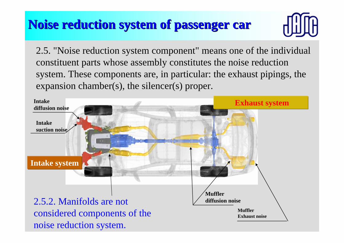
Noise reduction system of Noise reduction system of ppassenger assenger carcar
2.5.2. Manifolds are not considered components of the noise reduction system.
2.5. "Noise reduction system component" means one of the individual constituent parts whose assembly constitutes the noise reductionsystem. These components are, in particular: the exhaust pipings, the expansion chamber(s), the silencer(s) proper.
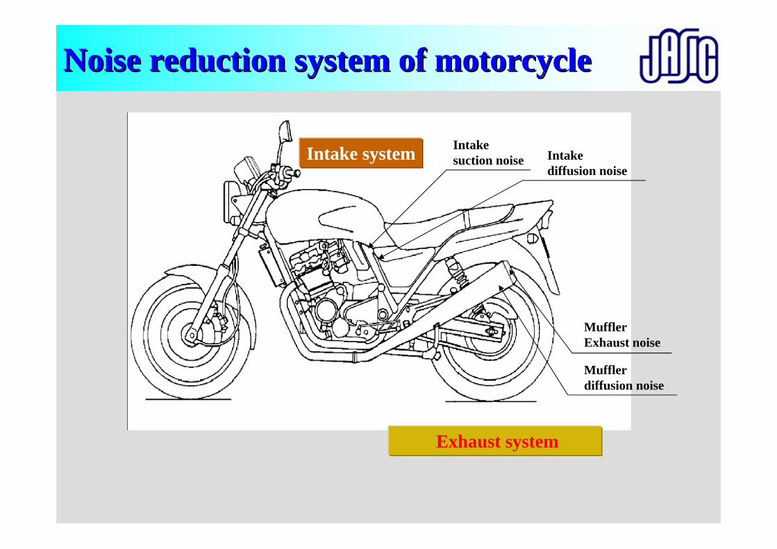
Noise reduction system of Noise reduction system of mmotorcycleotorcycle
Exhaust system
Intake system Intake suction noise
MufflerExhaust noise
Muffler diffusion noise
Intake diffusion noise

Preparation of Vehicle(Fuel, Temperature, Weight, Tire air pressure, Pulsation)
Test Facilities(Test track, Road surface, Instruments)
Miscellaneous
Calibration
Test (Purpose, method)
Calibration (R51:0.5dB)
Selection of vehicle(Definition, Experience)
Correction (R41)
Evaluation(Calculation, Deviation)
Measuring condition(Entry speed, Choice of gear ratio)
Setting of instruments
Approval
Marking, Label COP
Application Common item
Individual item
Penalties
R41/R51 Test R41/R51 Test ProceduresProcedures
Overview of presentationsOverview of presentations
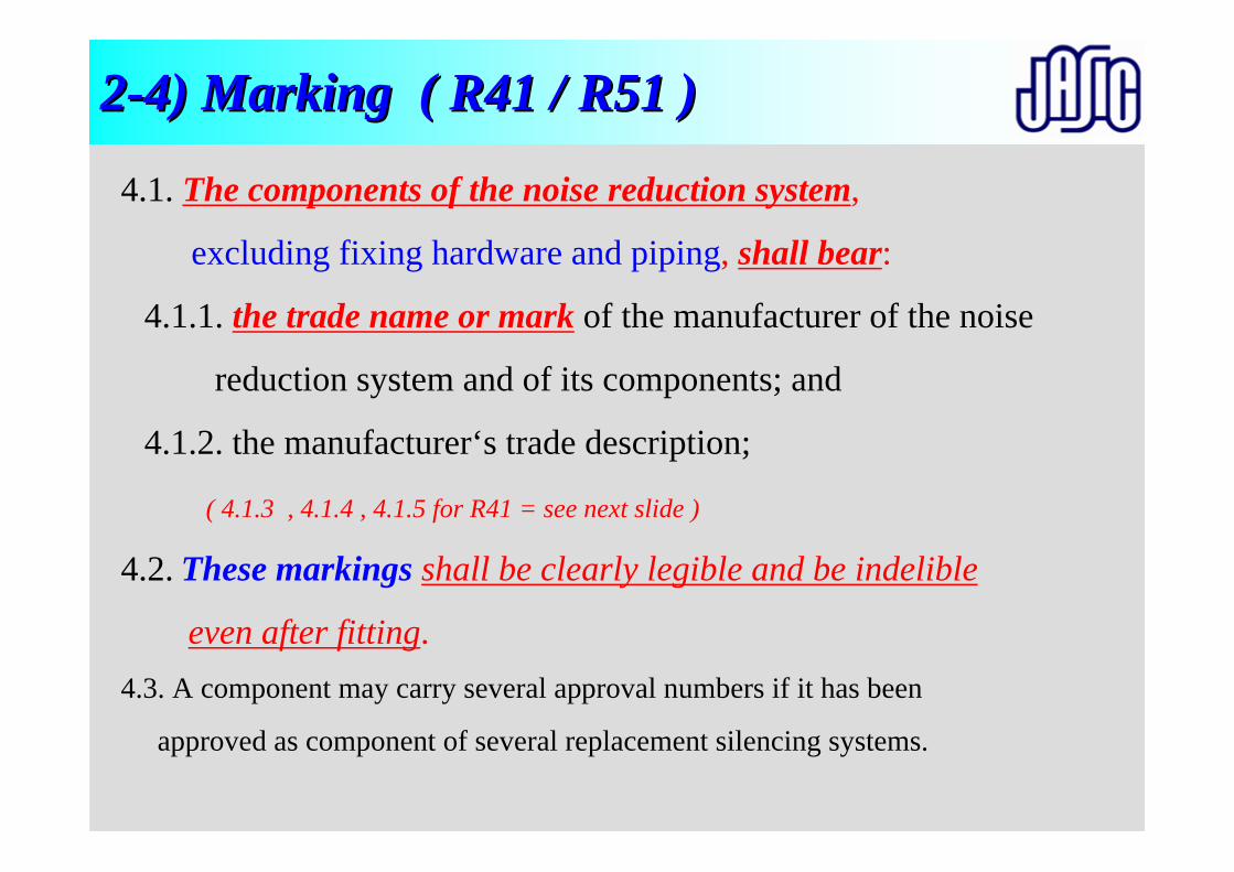
22--4) Marking ( R41 / R51 )4) Marking ( R41 / R51 )
4.1. The components of the noise reduction system,
excluding fixing hardware and piping, shall bear:
4.1.1. the trade name or mark of the manufacturer of the noise
reduction system and of its components; and
4.1.2. the manufacturer‘s trade description;
( 4.1.3 , 4.1.4 , 4.1.5 for R41 = see next slide )
4.2. These markings shall be clearly legible and be indelible
even after fitting.4.3. A component may carry several approval numbers if it has been
approved as component of several replacement silencing systems.
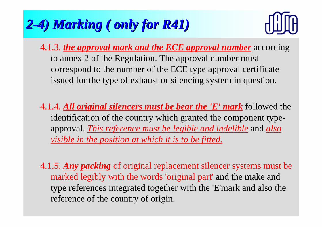
22--4) Marking ( only for R41)4) Marking ( only for R41)4.1.3. the approval mark and the ECE approval number according
to annex 2 of the Regulation. The approval number must correspond to the number of the ECE type approval certificate issued for the type of exhaust or silencing system in question.
4.1.4. All original silencers must be bear the 'E' mark followed the identification of the country which granted the component type-approval. This reference must be legible and indelible and also visible in the position at which it is to be fitted.
4.1.5. Any packing of original replacement silencer systems must be marked legibly with the words 'original part' and the make and type references integrated together with the 'E'mark and also the reference of the country of origin.
Preparation of Vehicle(Fuel, Temperature, Weight, Tire air pressure, Pulsation)
Test Facilities(Test track, Road surface, Instruments)
Miscellaneous
Calibration
Test (Purpose, method)
Calibration (R51:0.5dB)
Selection of vehicle(Definition, Experience)
Correction (R41)
Evaluation(Calculation, Deviation)
Measuring condition(Entry speed, Choice of gear ratio)
Setting of instruments
Approval
Marking, Label COP
Application Common item
Individual item
Penalties
R41/R51 Test R41/R51 Test ProceduresProcedures
Overview of presentationsOverview of presentations
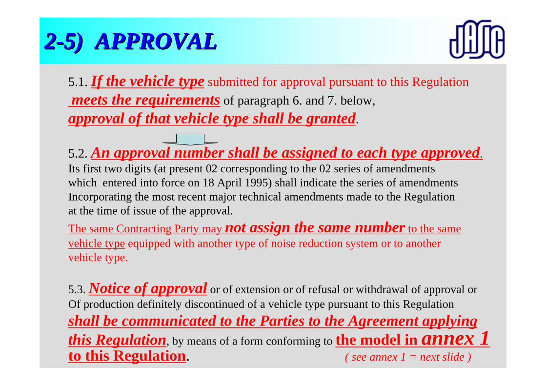
5.1. If the vehicle type submitted for approval pursuant to this Regulation meets the requirements of paragraph 6. and 7. below, approval of that vehicle type shall be granted.
5.2. An approval number shall be assigned to each type approved.Its first two digits (at present 02 corresponding to the 02 series of amendments which entered into force on 18 April 1995) shall indicate the series of amendments Incorporating the most recent major technical amendments made to the Regulation at the time of issue of the approval. The same Contracting Party may not assign the same number to the same vehicle type equipped with another type of noise reduction system or to another vehicle type.
5.3. Notice of approval or of extension or of refusal or withdrawal of approval or Of production definitely discontinued of a vehicle type pursuant to this Regulation shall be communicated to the Parties to the Agreement applying this Regulation, by means of a form conforming to the model in annex 1to this Regulation. ( see annex 1 = next slide )
22--5) APPROVAL5) APPROVAL
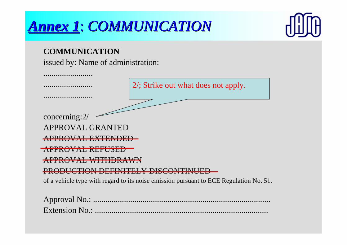
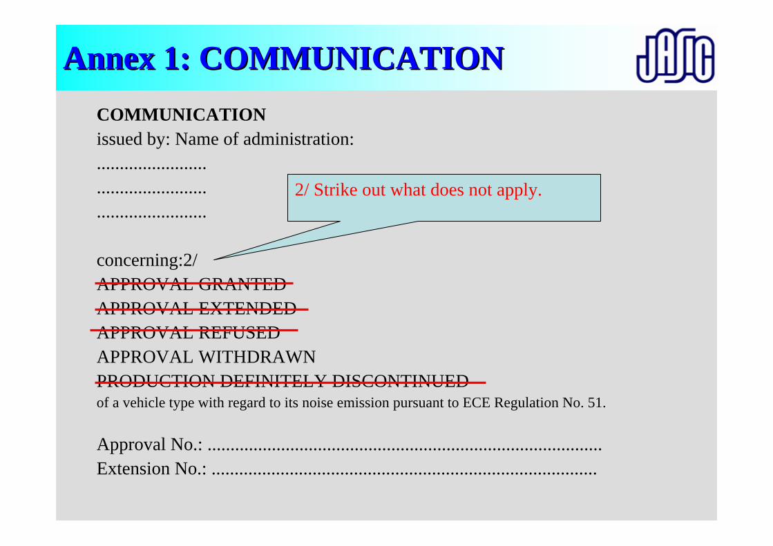
COMMUNICATIONissued by: Name of administration:........................................................................
concerning:2/APPROVAL GRANTEDAPPROVAL EXTENDEDAPPROVAL REFUSEDAPPROVAL WITHDRAWNPRODUCTION DEFINITELY DISCONTINUEDof a vehicle type with regard to its noise emission pursuant to ECE Regulation No. 51.
Approval No.: ......................................................................................Extension No.: ....................................................................................
Annex 1Annex 1: : COMMUNICATIONCOMMUNICATION
2/; Strike out what does not apply.
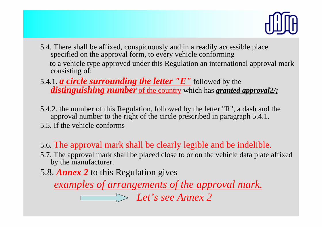
5.4. There shall be affixed, conspicuously and in a readily accessible place specified on the approval form, to every vehicle conforming to a vehicle type approved under this Regulation an international approval mark consisting of:
5.4.1. a circle surrounding the letter "E" followed by the distinguishing number of the country which has granted approval2/;
5.4.2. the number of this Regulation, followed by the letter "R", a dash and the approval number to the right of the circle prescribed in paragraph 5.4.1.
5.5. If the vehicle conforms
5.6. The approval mark shall be clearly legible and be indelible.5.7. The approval mark shall be placed close to or on the vehicle data plate affixed
by the manufacturer.5.8. Annex 2 to this Regulation gives
examples of arrangements of the approval mark.Let’s see Annex 2
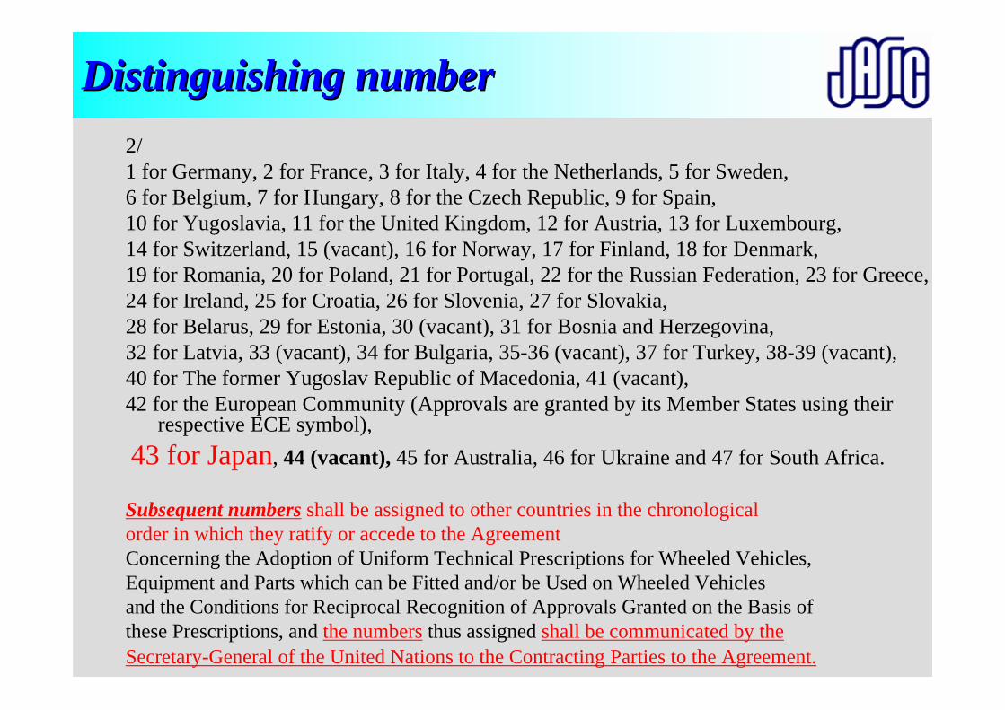
Distinguishing numberDistinguishing number2/1 for Germany, 2 for France, 3 for Italy, 4 for the Netherlands, 5 for Sweden, 6 for Belgium, 7 for Hungary, 8 for the Czech Republic, 9 for Spain, 10 for Yugoslavia, 11 for the United Kingdom, 12 for Austria, 13 for Luxembourg, 14 for Switzerland, 15 (vacant), 16 for Norway, 17 for Finland, 18 for Denmark, 19 for Romania, 20 for Poland, 21 for Portugal, 22 for the Russian Federation, 23 for Greece,24 for Ireland, 25 for Croatia, 26 for Slovenia, 27 for Slovakia, 28 for Belarus, 29 for Estonia, 30 (vacant), 31 for Bosnia and Herzegovina, 32 for Latvia, 33 (vacant), 34 for Bulgaria, 35-36 (vacant), 37 for Turkey, 38-39 (vacant), 40 for The former Yugoslav Republic of Macedonia, 41 (vacant), 42 for the European Community (Approvals are granted by its Member States using their
respective ECE symbol),43 for Japan, 44 (vacant), 45 for Australia, 46 for Ukraine and 47 for South Africa.
Subsequent numbers shall be assigned to other countries in the chronological order in which they ratify or accede to the AgreementConcerning the Adoption of Uniform Technical Prescriptions for Wheeled Vehicles,Equipment and Parts which can be Fitted and/or be Used on Wheeled Vehicles and the Conditions for Reciprocal Recognition of Approvals Granted on the Basis of these Prescriptions, and the numbers thus assigned shall be communicated by theSecretary-General of the United Nations to the Contracting Parties to the Agreement.
Approval labelApproval label
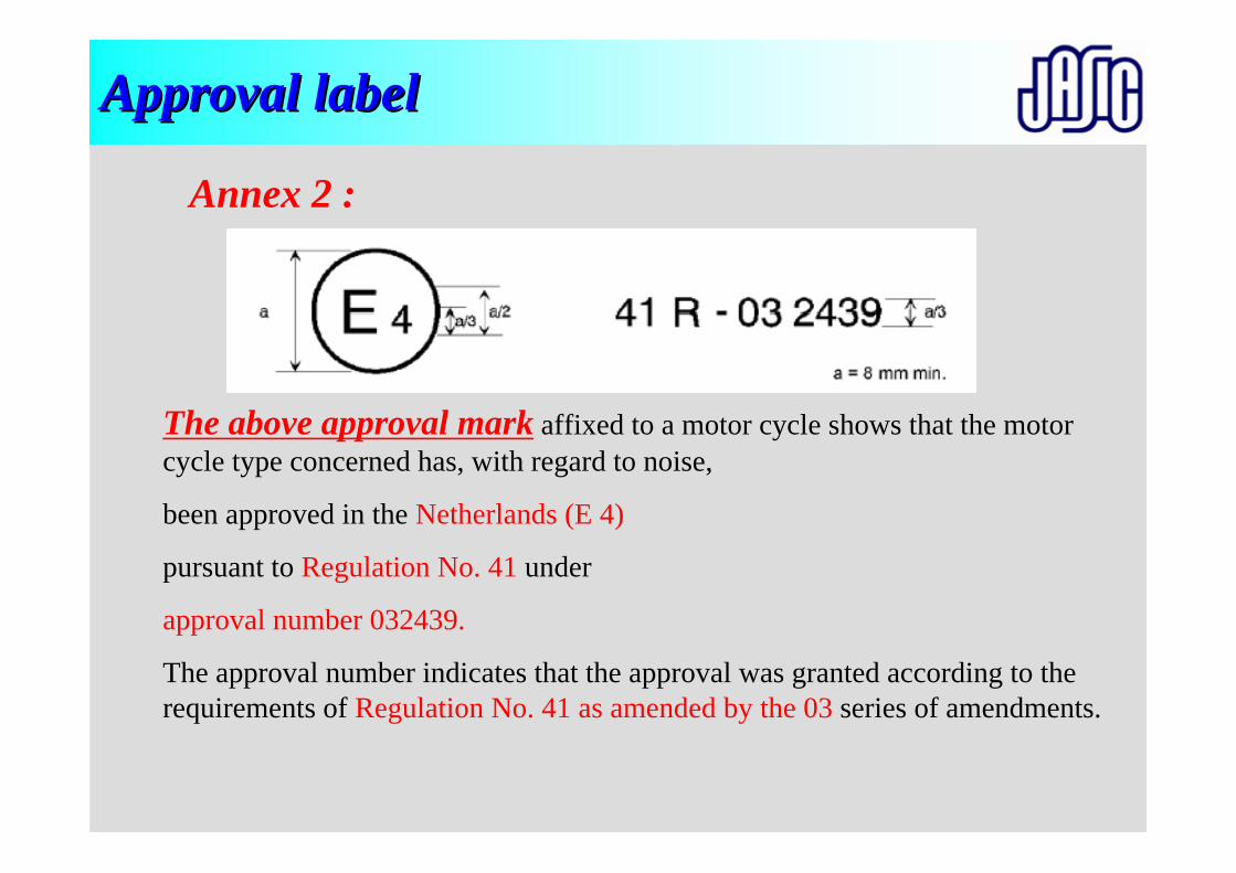
The above approval mark affixed to a motor cycle shows that the motor cycle type concerned has, with regard to noise,
been approved in the Netherlands (E 4)
pursuant to Regulation No. 41 under
approval number 032439.
The approval number indicates that the approval was granted according to the requirements of Regulation No. 41 as amended by the 03 series of amendments.
Annex 2 :
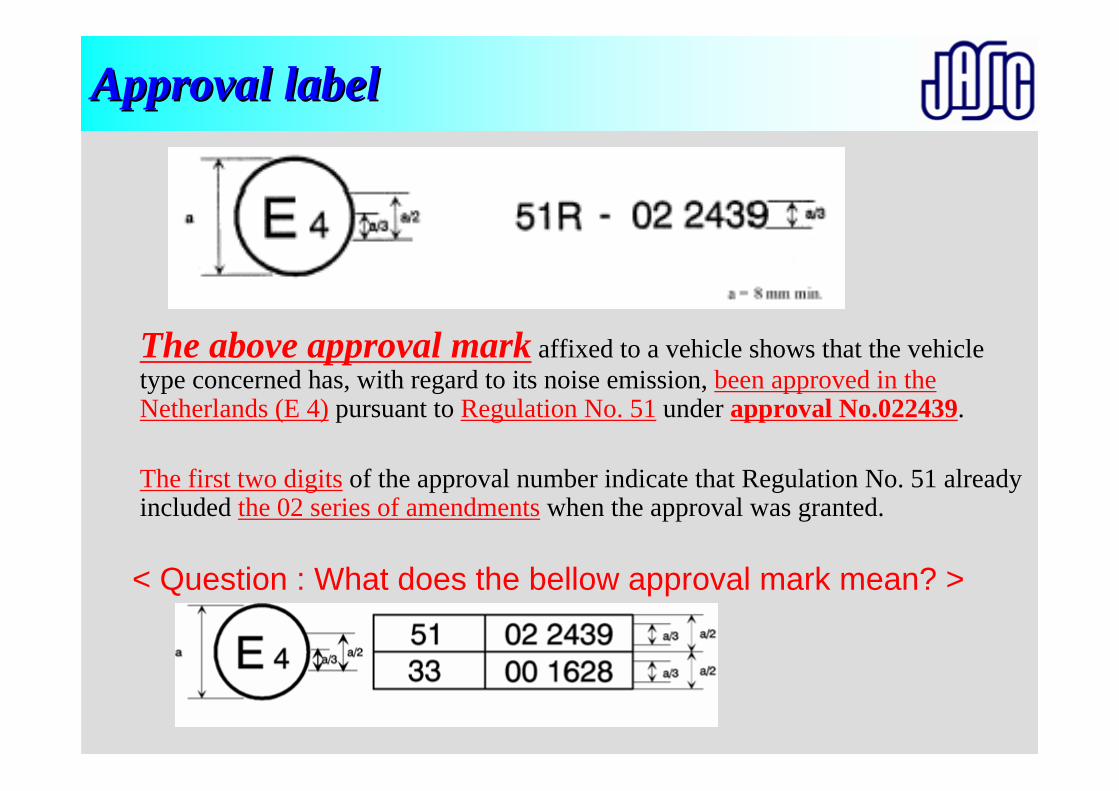
The above approval mark affixed to a vehicle shows that the vehicle type concerned has, with regard to its noise emission, been approved in the Netherlands (E 4) pursuant to Regulation No. 51 under approval No.022439.
The first two digits of the approval number indicate that Regulation No. 51 already included the 02 series of amendments when the approval was granted.
Approval labelApproval label
< Question : What does the bellow approval mark mean? >

Preparation of Vehicle(Fuel, Temperature, Weight, Tire air pressure, Pulsation)
Test Facilities(Test track, Road surface, Instruments)
Miscellaneous
Calibration
Test (Purpose, method)
Calibration (R51:0.5dB)
Selection of vehicle(Definition, Experience)
Correction (R41)
Evaluation(Calculation, Deviation)
Measuring condition(Entry speed, Choice of gear ratio)
Setting of instruments
Approval
Marking, Label COP
Application Common item
Individual item
Penalties
R41/R51 Test R41/R51 Test ProceduresProcedures
Overview of presentationsOverview of presentations
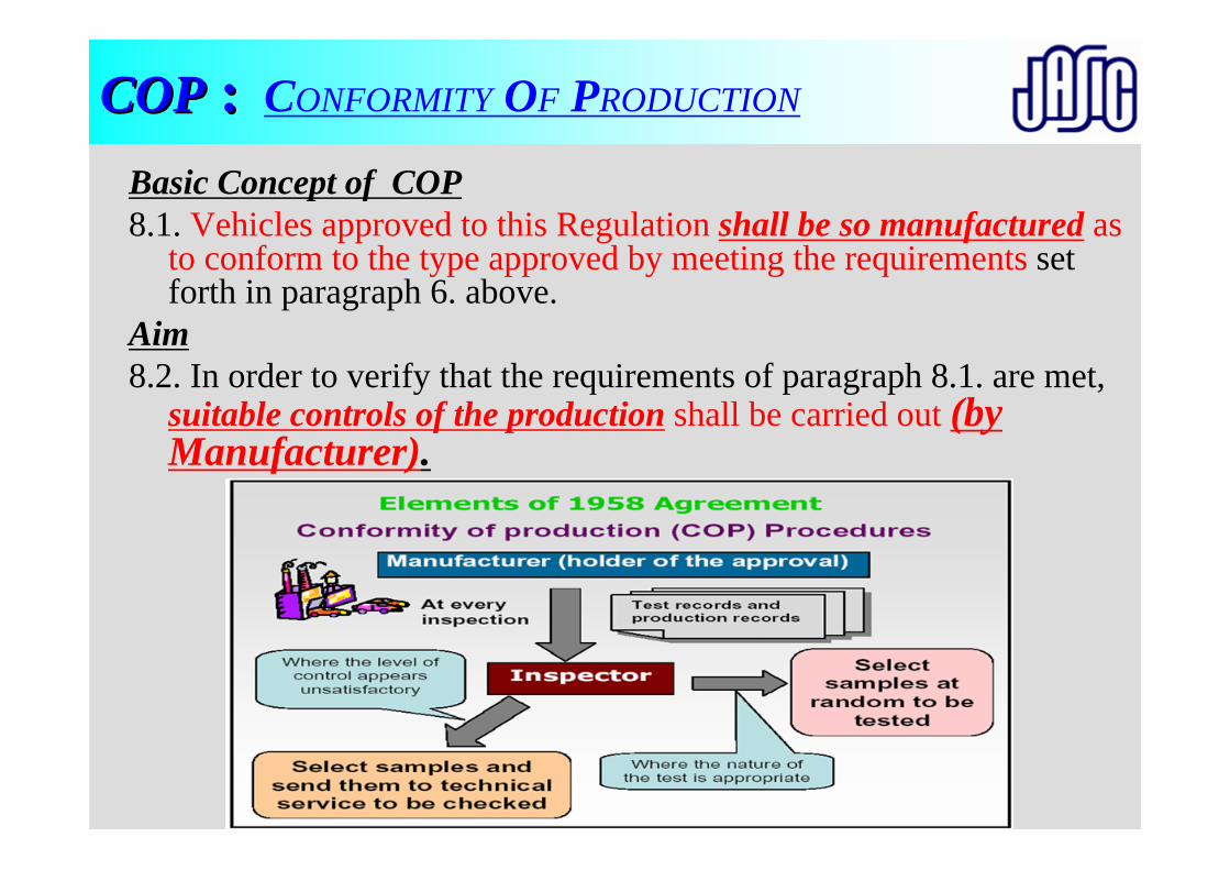
COPCOP :: CONFORMITY OF PRODUCTION
Basic Concept of COP8.1. Vehicles approved to this Regulation shall be so manufactured as
to conform to the type approved by meeting the requirements set forth in paragraph 6. above.
Aim8.2. In order to verify that the requirements of paragraph 8.1. are met,
suitable controls of the production shall be carried out (by Manufacturer).
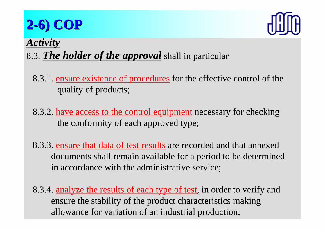
Activity8.3. The holder of the approval shall in particular
8.3.1. ensure existence of procedures for the effective control of the quality of products;
8.3.2. have access to the control equipment necessary for checking the conformity of each approved type;
8.3.3. ensure that data of test results are recorded and that annexed documents shall remain available for a period to be determined in accordance with the administrative service;
8.3.4. analyze the results of each type of test, in order to verify and ensure the stability of the product characteristics making allowance for variation of an industrial production;
22--6) COP6) COP
Activity8.3.5. ensure that for each type of product at least the tests prescribed
in annex 7 to this Regulation are carried out;
8.3.6. ensure that any sampling or test pieces giving evidence of non-conformity with the type of test considered shall give rise to another sampling and another test. All the necessary steps shall be taken to re-establish the conformity of the corresponding production.
See annex 7 :CHECKS ON CONFORMITY OF PRODUCTION
22--6) COP6) COP
Annex 7 ( R51 ) :Annex 7 ( R51 ) :CHECKS ON CONFORMITY OF PRODUCTION
1. GeneralThese requirements are consistent with the test to be held to check conformity of production according to paragraphs 8.3.5. and 8.4.3. of this Regulation.
2. Testing procedureThe test site and measuring instruments shall be those as described in annex 3.
3. SamplingOne vehicle has to be chosen. If after the test of paragraph 4.1. the vehicle is not considered to conform to the requirements of thisRegulation, two more vehicles have to be tested.
Annex 7 ( R51 ) :Annex 7 ( R51 ) :CHECKS ON CONFORMITY OF PRODUCTION
4. Evaluation of the results4.1. If the sound level of the vehicle tested pursuant to paragraphs 1 and
2 does not exceed by more than 1 dB (A) the limit valueprescribed in paragraph 6.2.2. of this Regulation, for measurement according to paragraph 2.1. above, and in paragraph 3 of annex 6 to this Regulation, for measurement according to paragraph 2.2. above, the vehicle type shall be considered to conform to the requirements of this Regulation.
4.2. If the vehicle tested according to paragraph 4.1. does not satisfy the requirements laid down in that paragraph, two more vehicles of the same type have to be tested pursuant to paragraphs 1 and 2.
Annex 7 ( R51 ) :Annex 7 ( R51 ) :CHECKS ON CONFORMITY OF PRODUCTION
4.3. If the sound level of the second and/or third vehicle of paragraph 4.2. exceeds by more than 1 dB(A) the limit values prescribed in paragraph 6.2.2. of this Regulation, the vehicle type shall be considered not to conform to the requirements of this Regulation and the manufacturer shall take the necessary measures to re-establish the conformity.
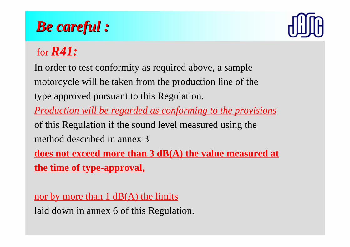
Be careful :Be careful :for R41:In order to test conformity as required above, a sample motorcycle will be taken from the production line of thetype approved pursuant to this Regulation. Production will be regarded as conforming to the provisionsof this Regulation if the sound level measured using the method described in annex 3 does not exceed more than 3 dB(A) the value measured at the time of type-approval,
nor by more than 1 dB(A) the limitslaid down in annex 6 of this Regulation.
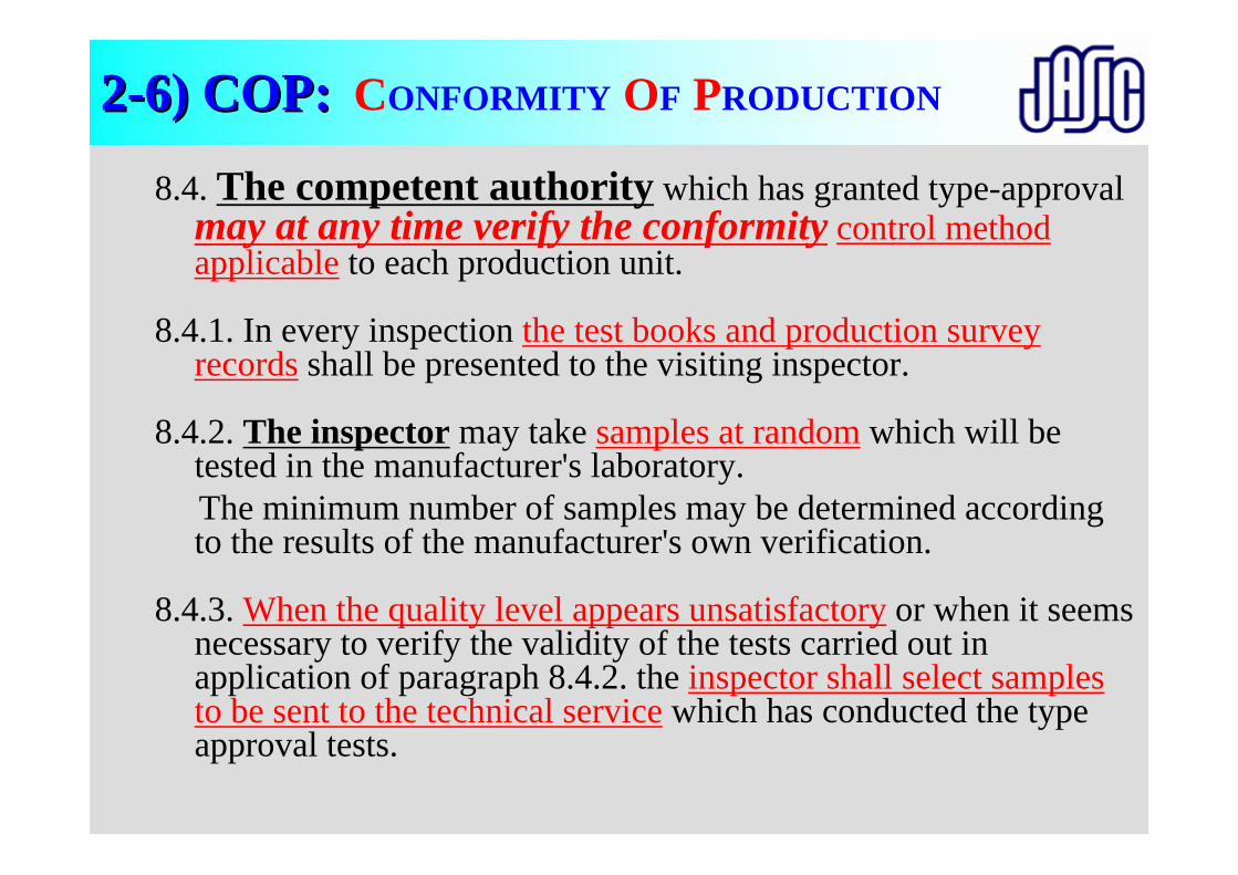
8.4. The competent authority which has granted type-approval may at any time verify the conformity control method applicable to each production unit.
8.4.1. In every inspection the test books and production survey records shall be presented to the visiting inspector.
8.4.2. The inspector may take samples at random which will be tested in the manufacturer's laboratory. The minimum number of samples may be determined according to the results of the manufacturer's own verification.
8.4.3. When the quality level appears unsatisfactory or when it seems necessary to verify the validity of the tests carried out in application of paragraph 8.4.2. the inspector shall select samples to be sent to the technical service which has conducted the type approval tests.
22--6) COP:6) COP: CONFORMITY OF PRODUCTION
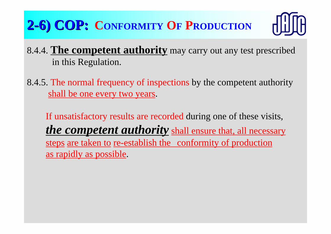
8.4.4. The competent authority may carry out any test prescribed in this Regulation.
8.4.5. The normal frequency of inspections by the competent authorityshall be one every two years.
If unsatisfactory results are recorded during one of these visits, the competent authority shall ensure that, all necessary steps are taken to re-establish the conformity of productionas rapidly as possible.
22--6) COP:6) COP: CONFORMITY OF PRODUCTION
22--7) Penalties7) Penalties
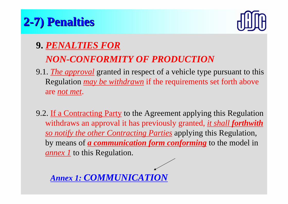
9. PENALTIES FORNON-CONFORMITY OF PRODUCTION
9.1. The approval granted in respect of a vehicle type pursuant to this Regulation may be withdrawn if the requirements set forth above are not met.
9.2. If a Contracting Party to the Agreement applying this Regulation withdraws an approval it has previously granted, it shall forthwithso notify the other Contracting Parties applying this Regulation, by means of a communication form conforming to the model in annex 1 to this Regulation.
Annex 1: COMMUNICATION
COMMUNICATIONissued by: Name of administration:........................................................................
concerning:2/APPROVAL GRANTEDAPPROVAL EXTENDEDAPPROVAL REFUSEDAPPROVAL WITHDRAWNPRODUCTION DEFINITELY DISCONTINUEDof a vehicle type with regard to its noise emission pursuant to ECE Regulation No. 51.
Approval No.: ......................................................................................Extension No.: ....................................................................................
Annex 1: COMMUNICATION Annex 1: COMMUNICATION
2/ Strike out what does not apply.

Preparation of Vehicle(Fuel, Temperature, Weight, Tire air pressure, Pulsation)
Test Facilities(Test track, Road surface, Instruments)
Miscellaneous
Calibration
Test (Purpose, method)
Calibration (R51:0.5dB)
Selection of vehicle(Definition, Experience)
Correction (R41)
Evaluation(Calculation, Deviation)
Measuring condition(Entry speed, Choice of gear ratio)
Setting of instruments
Approval
Marking, Label COP
Application Common item
Individual item
Penalties
R41/R51 Test R41/R51 Test ProceduresProcedures
Overview of presentationsOverview of presentations

Thank you very muchThank you very muchfor your attentionfor your attention
ECE R41, R51ECE R41, R51NOISE on motorcycles and passenger carsNOISE on motorcycles and passenger cars
S. YonezawaJASIC Noise-sub committee
Preparation of Vehicle(Fuel, Temperature, Weight, Tire air pressure, Pulsation)
Test Facilities(Test track, Road surface, Instruments)
Miscellaneous
Calibration
Test (Purpose, method)
Calibration (R51:0.5dB)
Selection of vehicle(Definition, Experience)
Correction (R41)
Evaluation(Calculation, Deviation)
Measuring condition(Entry speed, Choice of gear ratio)
Setting of instruments
Approval
Marking, Label COP
ApplicationCommon item
Individual item
Penalties
Overview of presentationsOverview of presentations
R41 test procedure
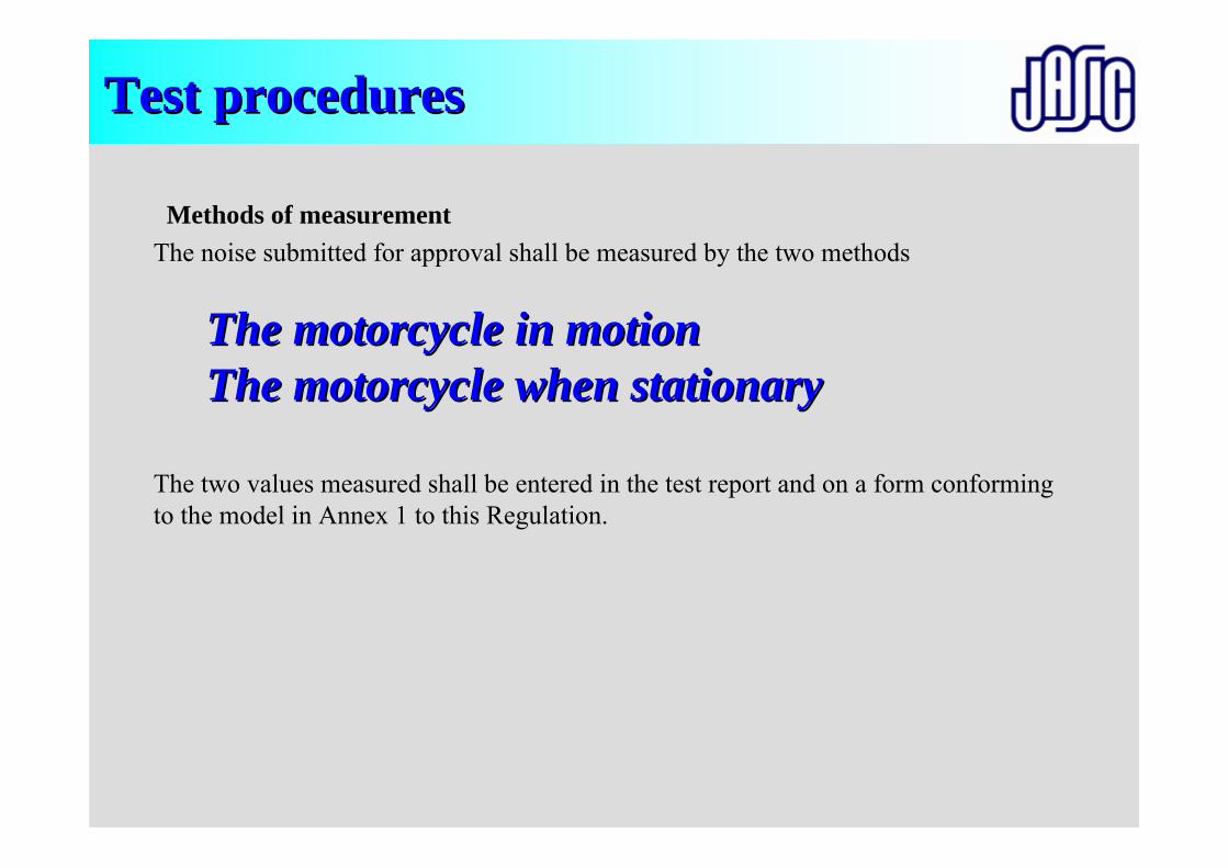
Test proceduresTest procedures
Methods of measurementThe noise submitted for approval shall be measured by the two methods
The motorcycle in motionThe motorcycle in motionThe motorcycle when stationaryThe motorcycle when stationary
The two values measured shall be entered in the test report and on a form conforming to the model in Annex 1 to this Regulation.
We call as
Acceleration noise (test)Acceleration noise (test)
Purpose of noise from vehicle in motionPurpose of noise from vehicle in motion
• Aim of noise measurements of the vehicle in motion are for granting the ECE type approval for motorcycles.
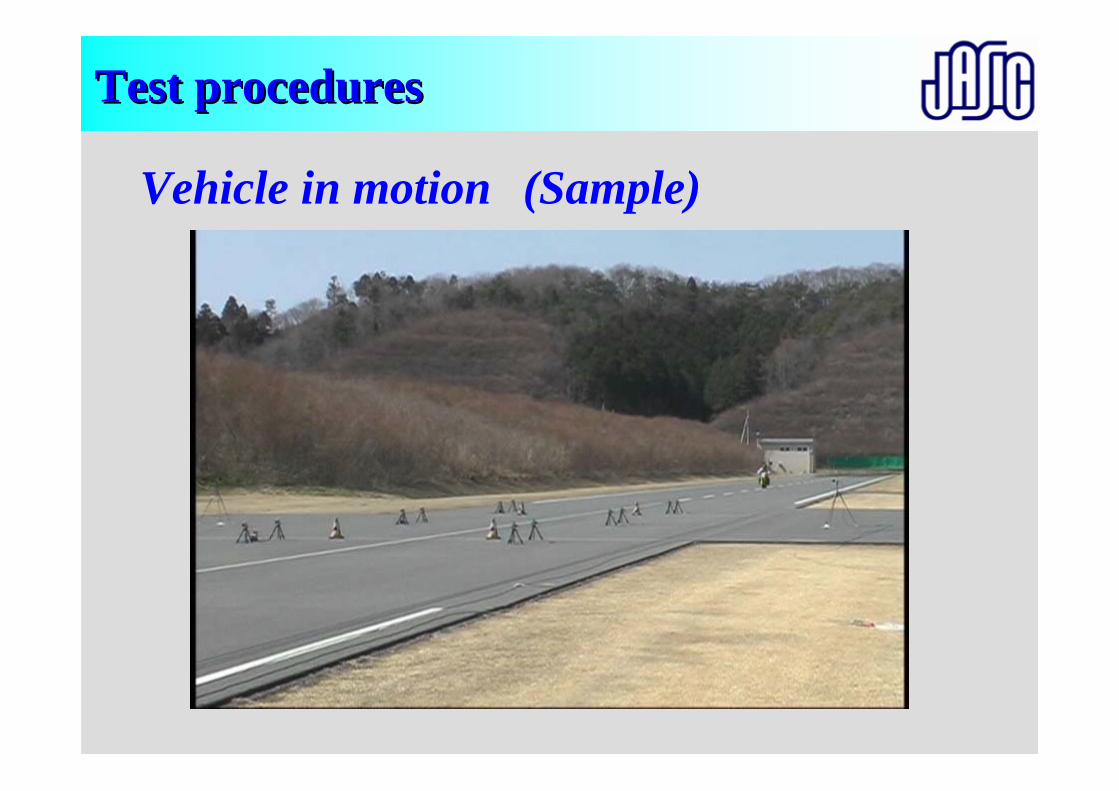
Test proceduresTest procedures
Vehicle in motion (Sample)
Test proceduresTest procedures
Methods of measurementThe noise submitted for approval shall be measured by the two methods
The motorcycle in motionThe motorcycle in motionThe motorcycle when stationaryThe motorcycle when stationary
The two values measured shall be entered in the test report and on a form conforming to the model in Annex 1 to this Regulation.
We call as
Stationary noise (test)Stationary noise (test)
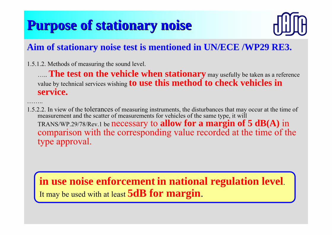
Purpose of stationary noise Purpose of stationary noise Aim of stationary noise test is mentioned in UN/ECE /WP29 RE3.
1.5.1.2. Methods of measuring the sound level.
….. The test on the vehicle when stationary may usefully be taken as a reference value by technical services wishing to use this method to check vehicles in service.
……..1.5.2.2. In view of the tolerances of measuring instruments, the disturbances that may occur at the time of
measurement and the scatter of measurements for vehicles of the same type, it will TRANS/WP.29/78/Rev.1 be necessary to allow for a margin of 5 dB(A) in comparison with the corresponding value recorded at the time of the type approval.
in use noise enforcement in national regulation level. It may be used with at least 5dB for margin.
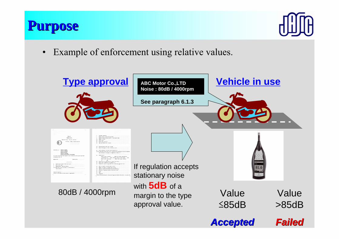
PurposePurpose
• Example of enforcement using relative values.
Type approval
80dB / 4000rpm
Vehicle in use
If regulation accepts stationary noise with 5dB of a margin to the type approval value.
ABC Motor Co.,LTDNoise : 80dB / 4000rpm
See paragraph 6.1.3
Value ≤85dB
AcceptedAccepted
Value >85dB
FailedFailed
Test proceduresTest procedures
Vehicle in stationary (Sample)
Test proceduresTest procedures
R41 for Motorcycles
Acceleration noise
Stationary noise
Preparation of Vehicle(Fuel, Temperature, Weight, Tire air pressure, Pulsation)
Test Facilities(Test track, Road surface, Instruments)
Miscellaneous
Calibration
Test (Purpose, method)
Calibration (R51:0.5dB)
Selection of vehicle(Definition, Experience)
Correction (R41)
Evaluation(Calculation, Deviation)
Measuring condition(Entry speed, Choice of gear ratio)
Setting of instruments
Approval
Marking, Label COP
ApplicationCommon item
Individual item
Penalties
Overview of presentationsOverview of presentations
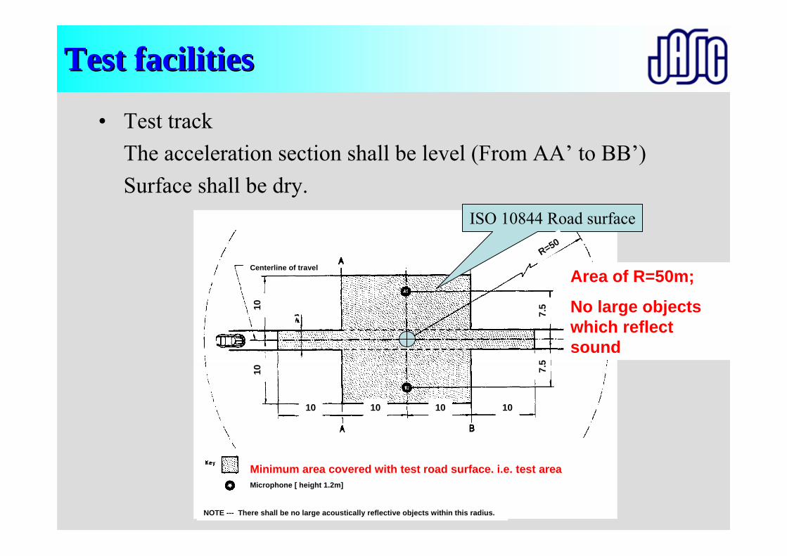
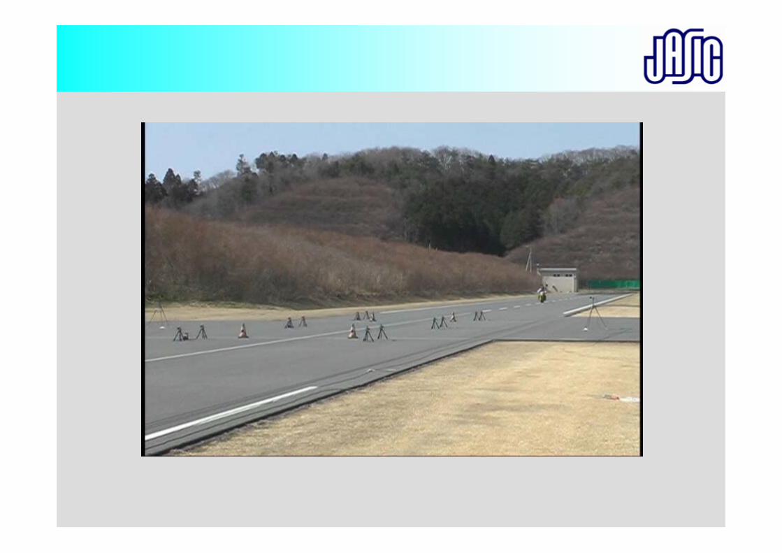
Test facilitiesTest facilities
• Test trackThe acceleration section shall be level (From AA’ to BB’)Surface shall be dry.
ISO 10844 Road surface
R=50
Minimum area covered with test road surface. i.e. test area
10
7.5
7.5
10101010
10
Microphone [ height 1.2m]
Centerline of travel
NOTE --- There shall be no large acoustically reflective objects within this radius.
Area of R=50m;
No large objects which reflect sound
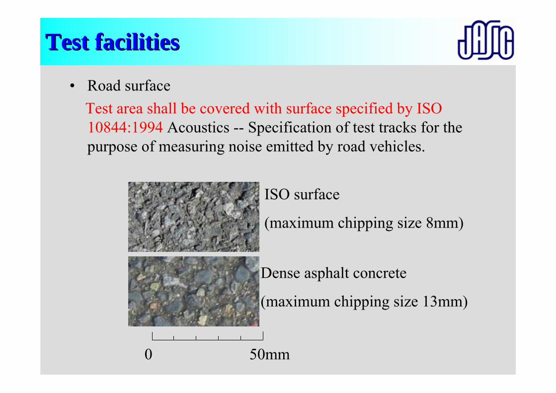
Test facilitiesTest facilities
• Road surfaceTest area shall be covered with surface specified by ISO 10844:1994 Acoustics -- Specification of test tracks for the purpose of measuring noise emitted by road vehicles.
0 50mm
ISO surface
(maximum chipping size 8mm)
Dense asphalt concrete
(maximum chipping size 13mm)
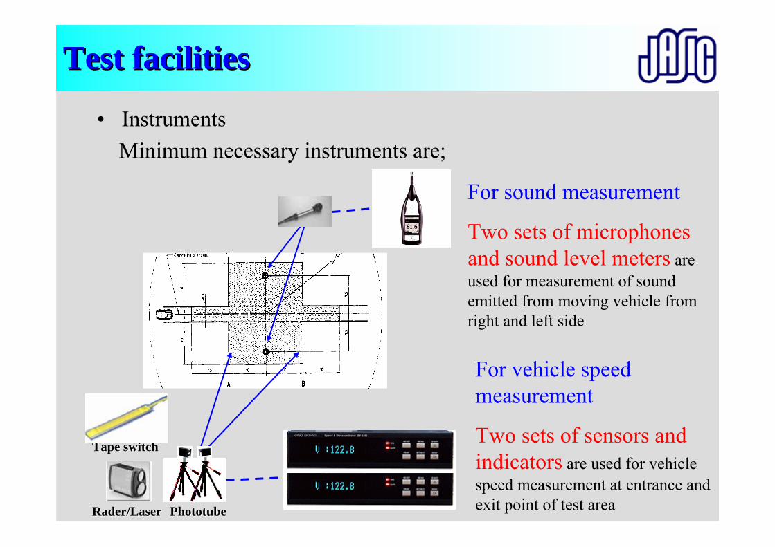
Test facilitiesTest facilities
• InstrumentsMinimum necessary instruments are;
For sound measurement
Two sets of microphones and sound level meters are used for measurement of sound emitted from moving vehicle from right and left side
For vehicle speed measurement
Two sets of sensors and indicators are used for vehicle speed measurement at entrance and exit point of test areaPhototubePhototubeRader/LaserRader/Laser
Tape switchTape switch
Test facilitiesTest facilities
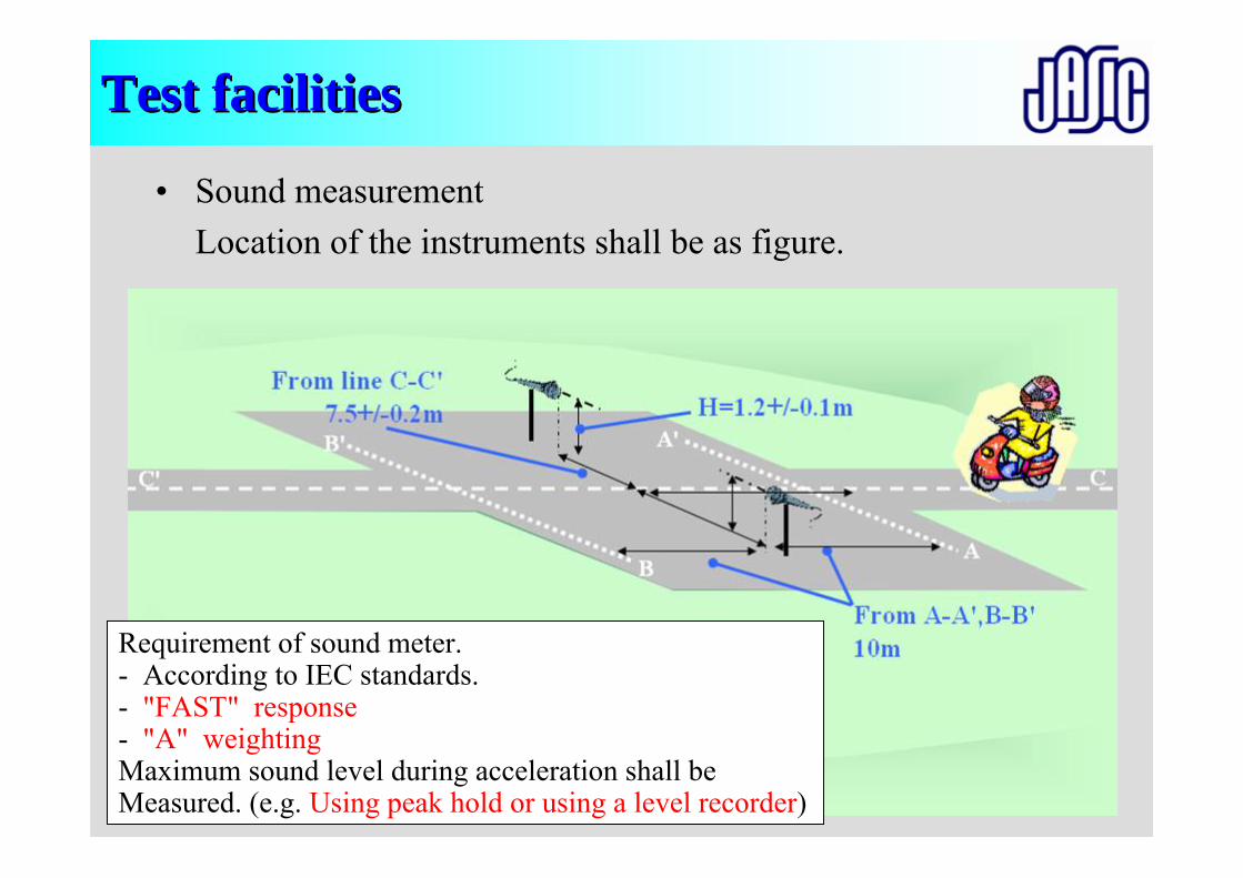
• Sound measurementLocation of the instruments shall be as figure.
Requirement of sound meter.- According to IEC standards.- "FAST" response- "A" weightingMaximum sound level during acceleration shall be Measured. (e.g. Using peak hold or using a level recorder)
Test facilitiesTest facilities
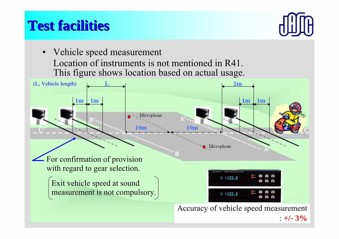
• Vehicle speed measurementLocation of instruments is not mentioned in R41.This figure shows location based on actual usage.
Exit vehicle speed at soundmeasurement is not compulsory.
For confirmation of provisionwith regard to gear selection.
Accuracy of vehicle speed measurement: +/- 3%
(L; Vehicle length)
Preparation of Vehicle(Fuel, Temperature, Weight, Tire air pressure, Pulsation)
Test Facilities(Test track, Road surface, Instruments)
Miscellaneous
Calibration
Test (Purpose, method)
Calibration (R51:0.5dB)
Selection of vehicle(Definition, Experience)
Correction (R41)
Evaluation(Calculation, Deviation)
Measuring condition(Entry speed, Choice of gear ratio)
Setting of instruments
Approval
Marking, Label COP
ApplicationCommon item
Individual item
Penalties
Overview of presentationsOverview of presentations
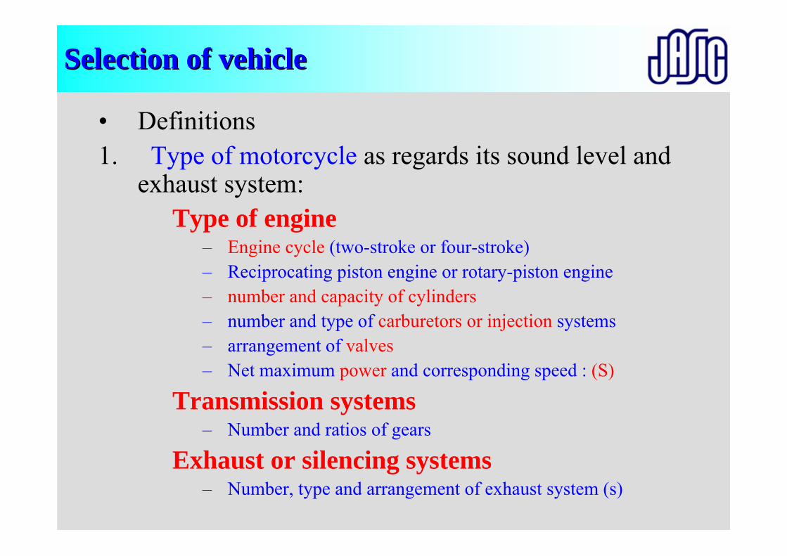
Selection of vehicleSelection of vehicle
• Definitions1. Type of motorcycle as regards its sound level and
exhaust system:Type of engine
– Engine cycle (two-stroke or four-stroke)– Reciprocating piston engine or rotary-piston engine– number and capacity of cylinders– number and type of carburetors or injection systems– arrangement of valves– Net maximum power and corresponding speed : (S)
Transmission systems– Number and ratios of gears
Exhaust or silencing systems– Number, type and arrangement of exhaust system (s)
Selection of vehicleSelection of vehicle
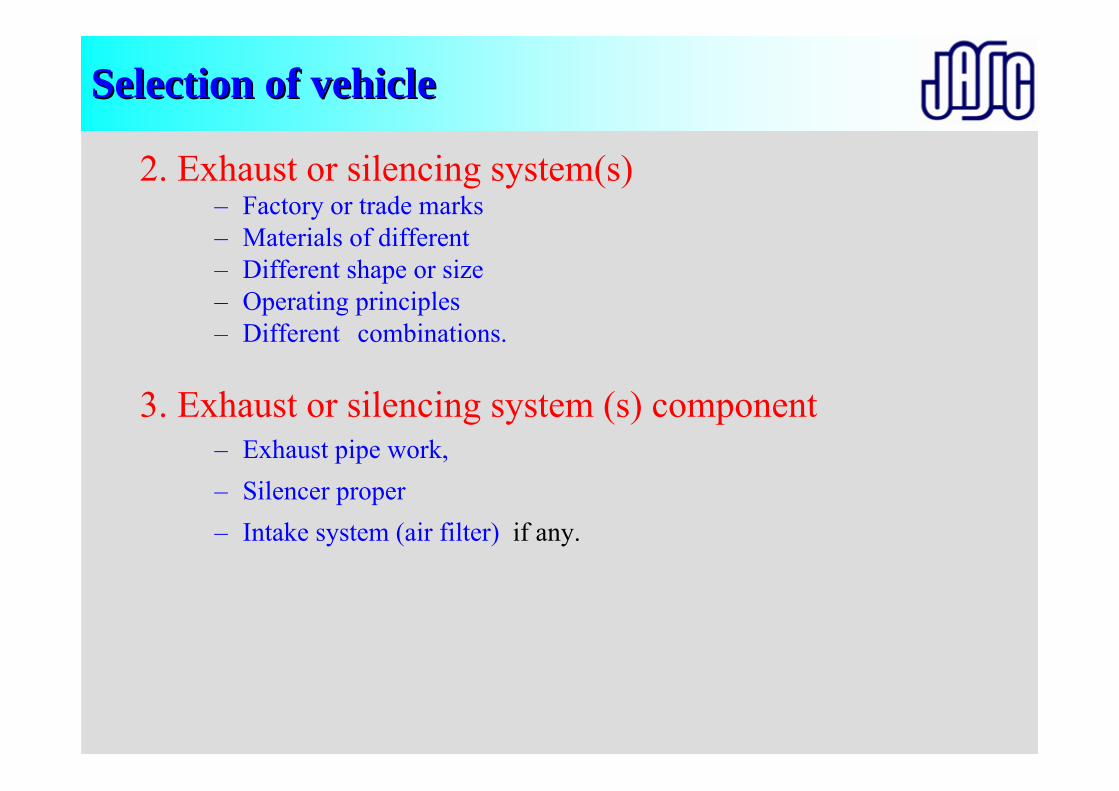
2. Exhaust or silencing system(s)– Factory or trade marks– Materials of different– Different shape or size– Operating principles – Different combinations.
3. Exhaust or silencing system (s) component– Exhaust pipe work,– Silencer proper– Intake system (air filter) if any.
Selection of vehicleSelection of vehicle
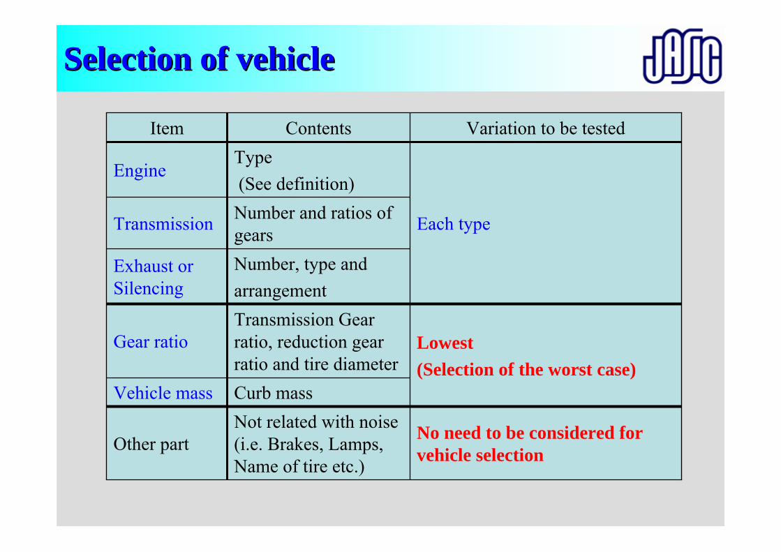
Item
Each typeNumber and ratios of gearsTransmission
Type(See definition)
Engine
Other part
Vehicle mass
Gear ratio
Exhaust or Silencing
Curb mass
Number, type andarrangement
No need to be considered for vehicle selection
Not related with noise (i.e. Brakes, Lamps, Name of tire etc.)
Lowest (Selection of the worst case)
Transmission Gear ratio, reduction gear ratio and tire diameter
Variation to be testedContents
Selection of vehicleSelection of vehicle
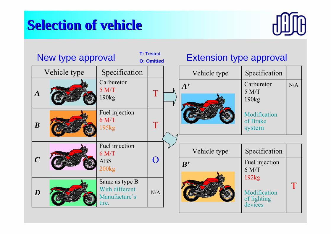
New type approval
N/A
Same as type BWith differentManufacture’s tire.
DD
Fuel injection6 M/TABS200kg
Fuel injection6 M/T195kg
Carburetor5 M/T190kg
Specification
TAA
O
T
CC
BB
Vehicle type
Extension type approval
N/ACarburetor5 M/T190kg
Modification of Brakesystem
AA’’
SpecificationVehicle type
T: TestedO: Omitted
T
Fuel injection6 M/T192kg
Modification of lighting devices
BB’’
SpecificationVehicle type
Preparation of Vehicle(Fuel, Temperature, Weight, Tire air pressure, Pulsation)
Test Facilities(Test track, Road surface, Instruments)
Miscellaneous
Calibration
Test (Purpose, method)
Calibration (R51:0.5dB)
Selection of vehicle(Definition, Experience)
Correction (R41)
Evaluation(Calculation, Deviation)
Measuring condition(Entry speed, Choice of gear ratio)
Setting of instruments
Approval
Marking, Label COP
ApplicationCommon item
Individual item
Penalties
Overview of presentationsOverview of presentations
Preparation of vehiclePreparation of vehicle
Motorcycle shall be in running order, including- Coolant - Oils - Fuel - Tool- Spare wheel - a Rider
Motorcycle engine shall be brought to the normal operating temperature.
Fans with an automatic actuating mechanism shall not be interfered with the sound measurements.
More than one driven wheel, only the drive provided for normal road operation may be used.
Sidecar must be removed.
Preparation of vehiclePreparation of vehicle
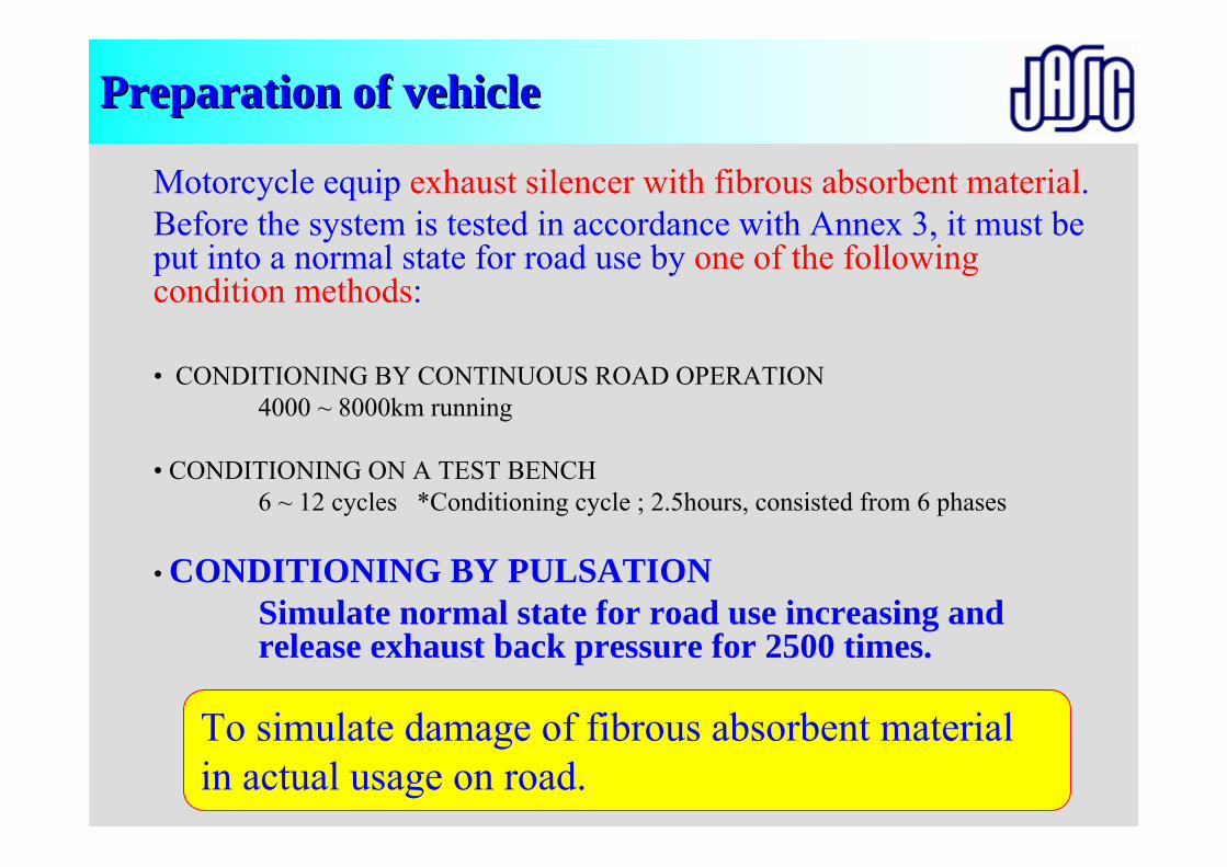
Motorcycle equip exhaust silencer with fibrous absorbent material.Before the system is tested in accordance with Annex 3, it must be put into a normal state for road use by one of the following condition methods:
• CONDITIONING BY CONTINUOUS ROAD OPERATION4000 ~ 8000km running
• CONDITIONING ON A TEST BENCH6 ~ 12 cycles *Conditioning cycle ; 2.5hours, consisted from 6 phases
• CONDITIONING BY PULSATIONSimulate normal state for road use increasing and release exhaust back pressure for 2500 times.
To simulate damage of fibrous absorbent material in actual usage on road.
Preparation of vehiclePreparation of vehicle
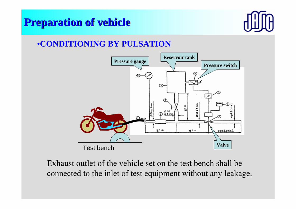
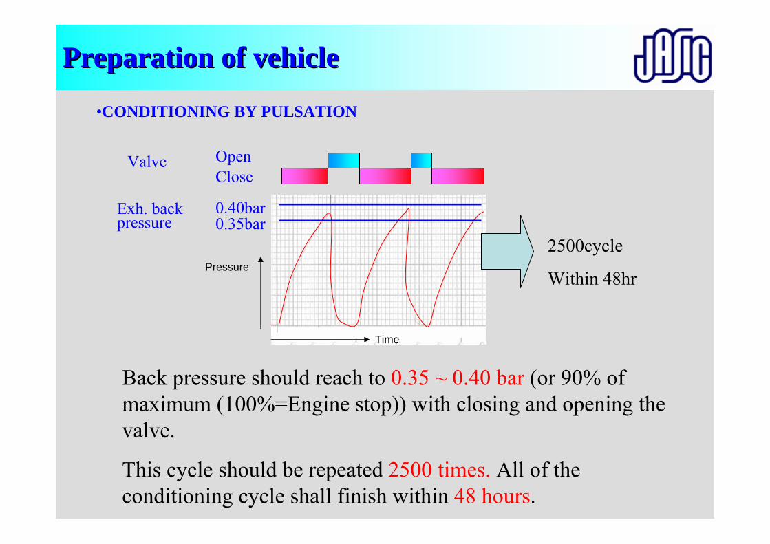
•CONDITIONING BY PULSATION
Exhaust outlet of the vehicle set on the test bench shall be connected to the inlet of test equipment without any leakage.
Test bench
Pressure gaugeReservoir tank
Pressure switch
Valve
Preparation of vehiclePreparation of vehicle
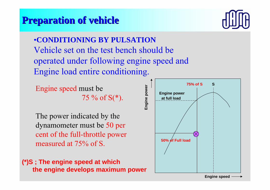
•CONDITIONING BY PULSATIONVehicle set on the test bench should beoperated under following engine speed and Engine load entire conditioning.
Engine speed must be 75 % of S(*).
The power indicated by the dynamometer must be 50 per cent of the full-throttle power measured at 75% of S.
S75% of S
Engine speed
Engi
ne p
ower
Engine powerat full load
50% of Full load
(*)S ; The engine speed at which the engine develops maximum power
Preparation of vehiclePreparation of vehicle
•CONDITIONING BY PULSATION
Back pressure should reach to 0.35 ~ 0.40 bar (or 90% of maximum (100%=Engine stop)) with closing and opening the valve.
This cycle should be repeated 2500 times. All of the conditioning cycle shall finish within 48 hours.
2500cycle
Within 48hr
0.40bar0.35bar
Valve OpenClose
Exh. back pressure
Time
Pressure
Preparation of Vehicle(Fuel, Temperature, Weight, Tire air pressure, Pulsation)
Test Facilities(Test track, Road surface, Instruments)
Miscellaneous
Calibration
Test (Purpose, method)
Calibration (R51:0.5dB)
Selection of vehicle(Definition, Experience)
Correction (R41)
Evaluation(Calculation, Deviation)
Measuring condition(Entry speed, Choice of gear ratio)
Setting of instruments
Approval
Marking, Label COP
ApplicationCommon item
Individual item
Penalties
Overview of presentationsOverview of presentations
CalibrationCalibration
• At the beginning and end of each series of measurementsthe sound level meter shall be calibrated in accordance with the manufacturer's instructions, using an appropriate sound source (e.g. piston phone).
Preparation of Vehicle(Fuel, Temperature, Weight, Tire air pressure, Pulsation)
Test Facilities(Test track, Road surface, Instruments)
Miscellaneous
Calibration
Test (Purpose, method)
Calibration (R51:0.5dB)
Selection of vehicle(Definition, Experience)
Correction (R41)
Evaluation(Calculation, Deviation)
Measuring condition(Entry speed, Choice of gear ratio)
Setting of instruments
Approval
Marking, Label COP
ApplicationCommon item
Individual item
Penalties
Overview of presentationsOverview of presentations
MiscellaneousMiscellaneous
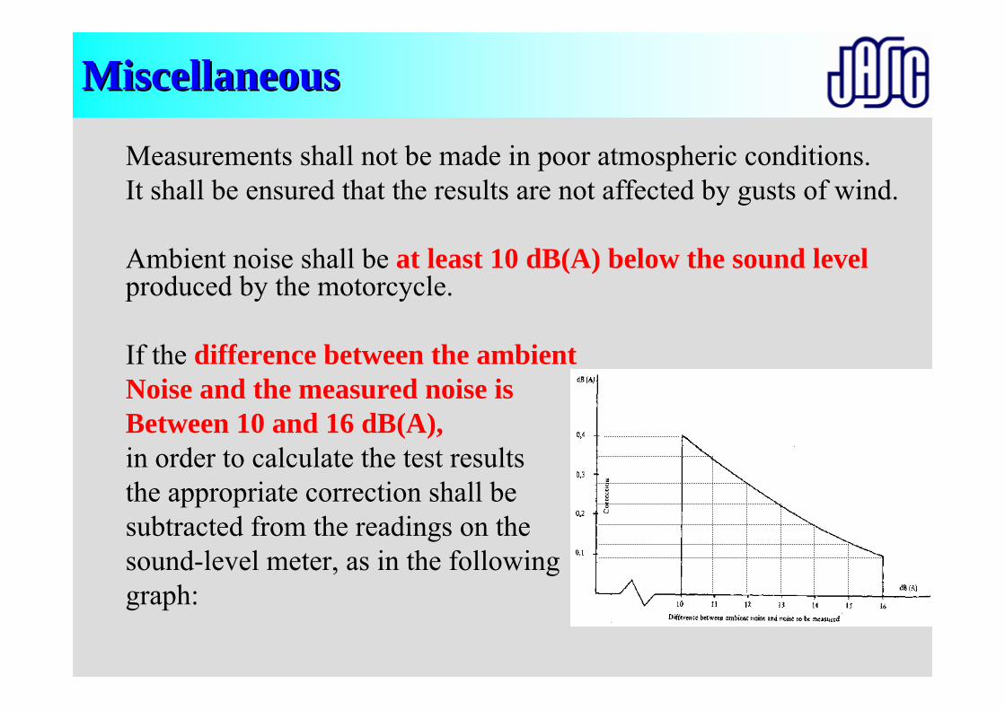
Measurements shall not be made in poor atmospheric conditions. It shall be ensured that the results are not affected by gusts of wind.
Ambient noise shall be at least 10 dB(A) below the sound levelproduced by the motorcycle.
If the difference between the ambientNoise and the measured noise is Between 10 and 16 dB(A),in order to calculate the test resultsthe appropriate correction shall be subtracted from the readings on the sound-level meter, as in the following graph:
Preparation of Vehicle(Fuel, Temperature, Weight, Tire air pressure, Pulsation)
Test Facilities(Test track, Road surface, Instruments)
Miscellaneous
Calibration
Test (method)
Calibration (R51:0.5dB)
Selection of vehicle(Definition, Experience)
Correction (R41)
Evaluation(Calculation, Deviation)
Measuring condition(Entry speed, Choice of gear ratio)
Setting of instruments
Approval
Marking, Label COP
ApplicationCommon item
Individual item
Penalties
Overview of presentationsOverview of presentations
TestTest
C' C
A
A'
B
B'
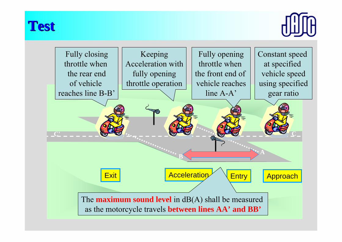
Constant speed at specified
vehicle speedusing specified
gear ratio
ApproachEntry
Fully openingthrottle when
the front end of vehicle reaches
line A-A’
Exit
Fully closingthrottle when the rear endof vehicle
reaches line B-B’
Acceleration
KeepingAcceleration with
fully openingthrottle operation
The maximum sound level in dB(A) shall be measured as the motorcycle travels between lines AA’ and BB’
Preparation of Vehicle(Fuel, Temperature, Weight, Tire air pressure, Pulsation)
Test Facilities(Test track, Road surface, Instruments)
Miscellaneous
Calibration
Test (method)
Calibration (R51:0.5dB)
Selection of vehicle(Definition, Experience)
Correction (R41)
Evaluation(Calculation, Deviation)
Measuring condition(Entry speed, Choice of gear ratio)
Setting of instruments
Approval
Marking, Label COP
ApplicationCommon item
Individual item
Penalties
Overview of presentationsOverview of presentations
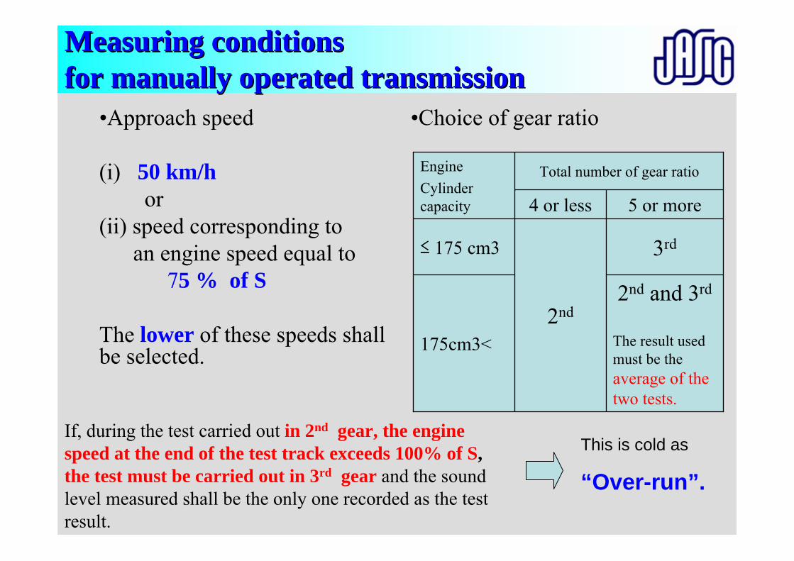
Measuring conditionsMeasuring conditionsfor manually operated transmissionfor manually operated transmission
•Approach speed
(i) 50 km/hor
(ii) speed corresponding to an engine speed equal to
75 % of S
The lower of these speeds shall be selected.
•Choice of gear ratio
2nd and 3rd
The result used must be the average of the two tests.
3rd
2nd
≤ 175 cm3
175cm3<
5 or more4 or less
Total number of gear ratioEngineCylinder capacity
If, during the test carried out in 2nd gear, the engine speed at the end of the test track exceeds 100% of S, the test must be carried out in 3rd gear and the sound level measured shall be the only one recorded as the test result.
This is cold as
“Over-run”.
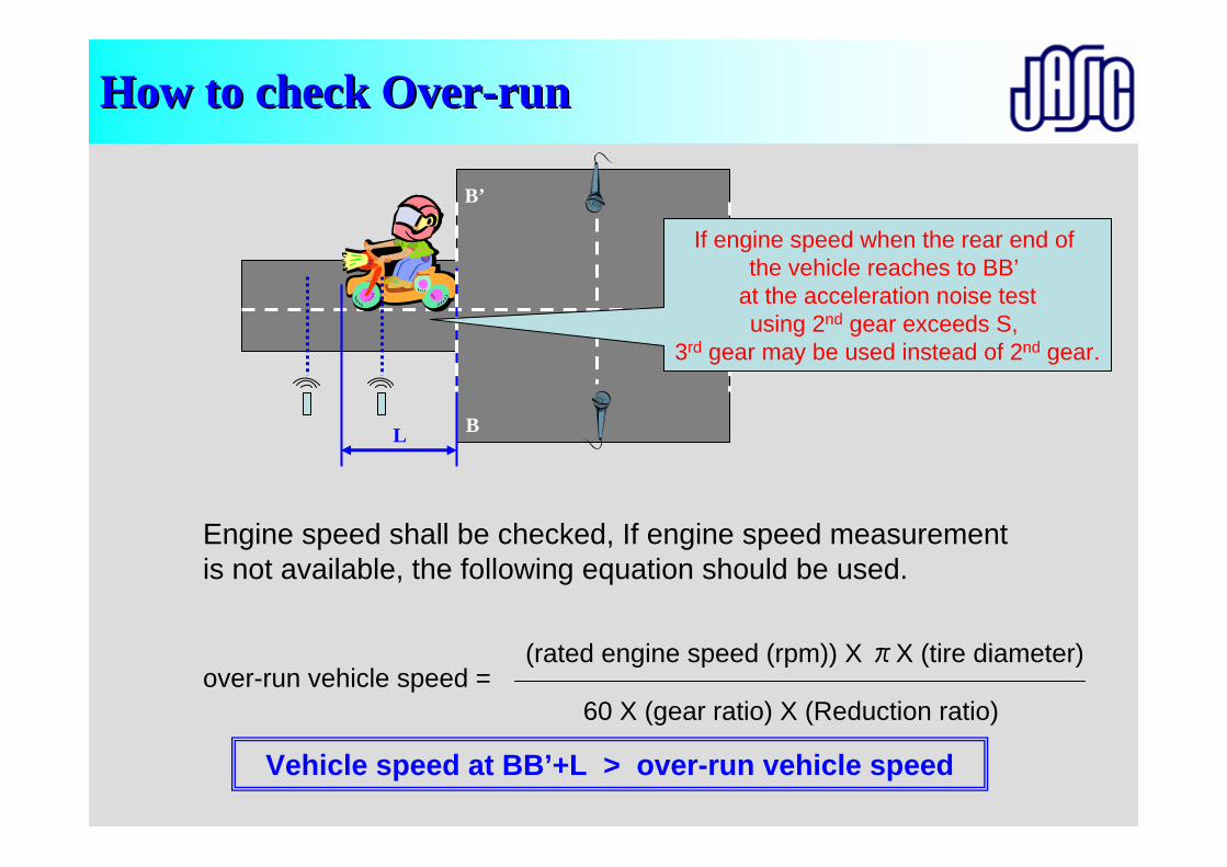
How to check OverHow to check Over--runrun
Vehicle speed at BB’+L > over-run vehicle speed
Engine speed shall be checked, If engine speed measurement is not available, the following equation should be used.
over-run vehicle speed =(rated engine speed (rpm)) X πX (tire diameter)
60 X (gear ratio) X (Reduction ratio)
B
B’
L
If engine speed when the rear end of the vehicle reaches to BB’
at the acceleration noise testusing 2nd gear exceeds S,
3rd gear may be used instead of 2nd gear.
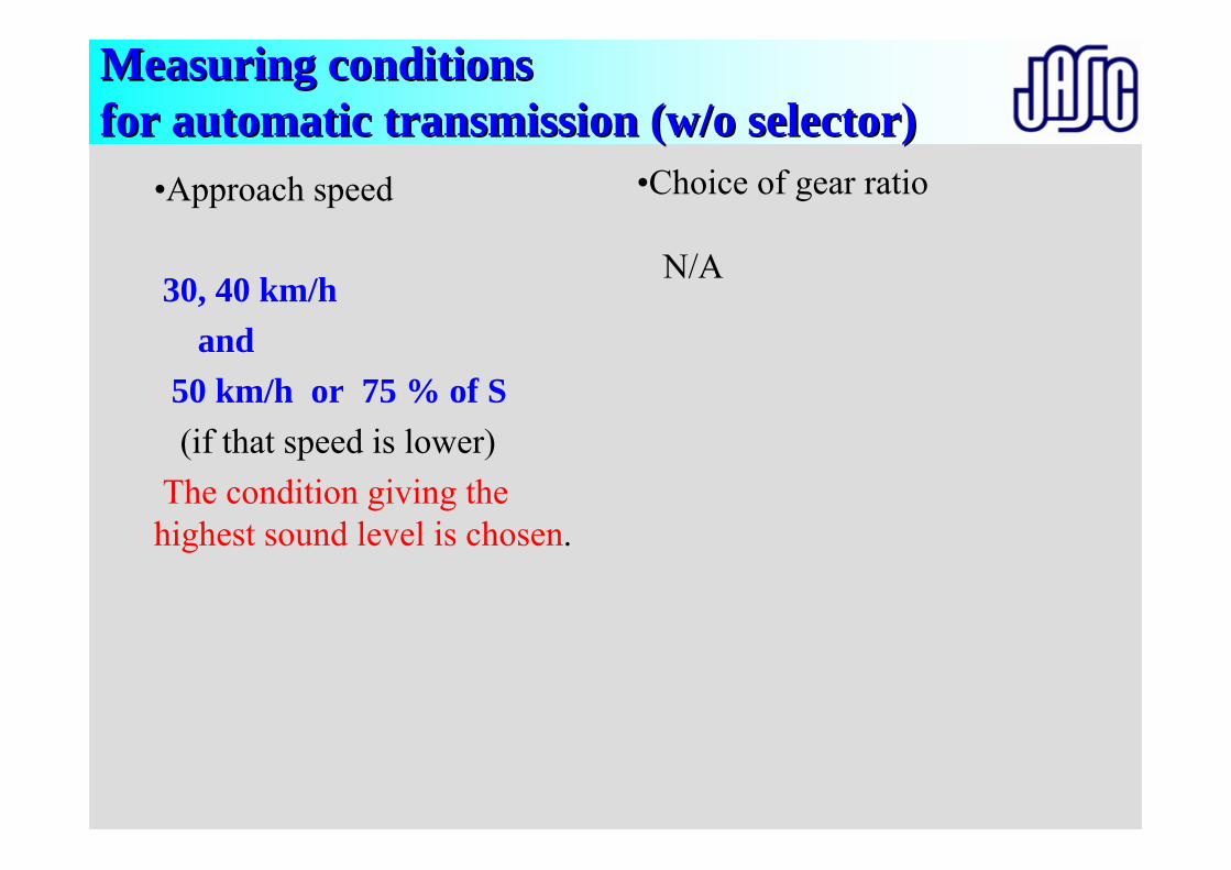
Measuring conditionsMeasuring conditionsfor automatic transmission (w/o selector)for automatic transmission (w/o selector)
•Approach speed
30, 40 km/h and
50 km/h or 75 % of S(if that speed is lower)
The condition giving the highest sound level is chosen.
•Choice of gear ratio
N/A
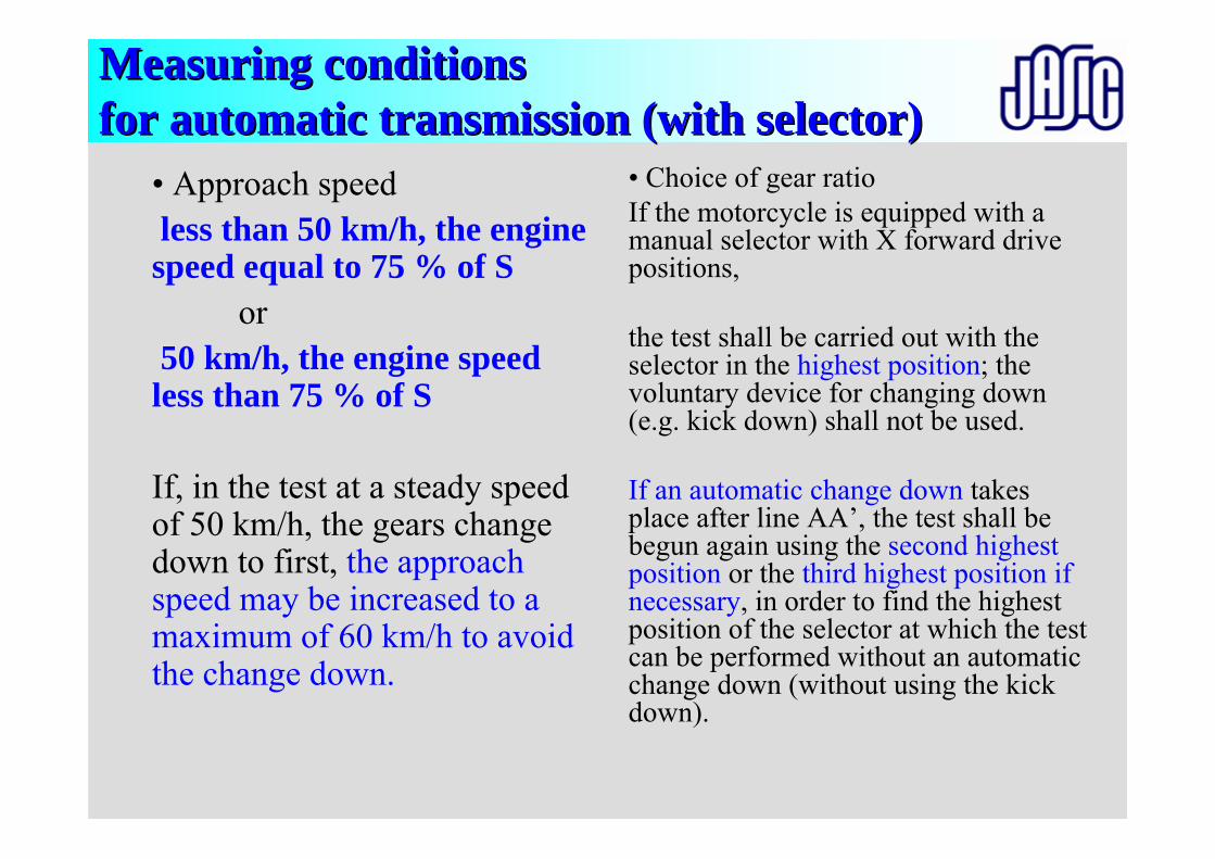
Measuring conditionsMeasuring conditionsfor automatic transmission (with selector)for automatic transmission (with selector)
• Approach speedless than 50 km/h, the engine speed equal to 75 % of S
or50 km/h, the engine speed less than 75 % of S
If, in the test at a steady speed of 50 km/h, the gears change down to first, the approach speed may be increased to a maximum of 60 km/h to avoid the change down.
• Choice of gear ratioIf the motorcycle is equipped with a manual selector with X forward drive positions,
the test shall be carried out with the selector in the highest position; the voluntary device for changing down (e.g. kick down) shall not be used.
If an automatic change down takes place after line AA’, the test shall be begun again using the second highest position or the third highest position if necessary, in order to find the highest position of the selector at which the test can be performed without an automatic change down (without using the kick down).
Preparation of Vehicle(Fuel, Temperature, Weight, Tire air pressure, Pulsation)
Test Facilities(Test track, Road surface, Instruments)
Miscellaneous
Calibration
Test (method)
Calibration (R51:0.5dB)
Selection of vehicle(Definition, Experience)
Correction (R41)
Evaluation(Calculation, Deviation)
Measuring condition(Entry speed, Choice of gear ratio)
Setting of instruments
Approval
Marking, Label COP
ApplicationCommon item
Individual item
Penalties
Overview of presentationsOverview of presentations
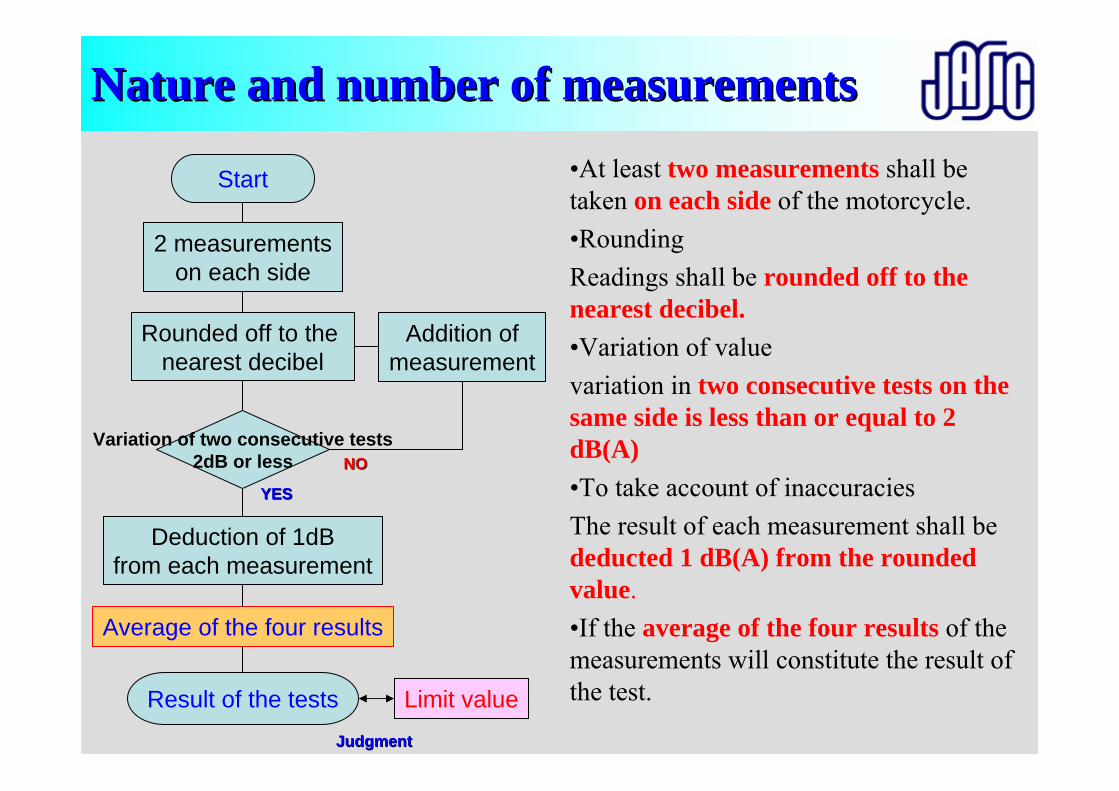
Nature and number of measurementsNature and number of measurements
Start
2 measurementson each side
Variation of two consecutive tests2dB or less
Rounded off to the nearest decibel
Addition ofmeasurement
Deduction of 1dBfrom each measurement
Average of the four results
Result of the tests Limit value
•At least two measurements shall be taken on each side of the motorcycle.•RoundingReadings shall be rounded off to the nearest decibel.•Variation of valuevariation in two consecutive tests on thesame side is less than or equal to 2 dB(A)•To take account of inaccuraciesThe result of each measurement shall be deducted 1 dB(A) from the rounded value.•If the average of the four results of the measurements will constitute the result of the test.
YESYES
NONO
JudgmentJudgment
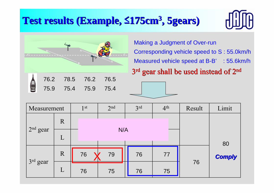
Test results (Example, Test results (Example, ≤≤175cm175cm33, 5gears), 5gears)
C' C
A
A'
B
B'
76.275.9
L
L
R
R
3rd gear
4th3rd2nd
2nd gear
1st Result LimitMeasurement
Making a Judgment of Over-run
76
76
78.575.4
76.275.9
76.575.4
79
75
76
76
77
75
X
Corresponding vehicle speed to S : 55.0km/hMeasured vehicle speed at B-B’ : 55.6km/h
33rdrd gear shall be used instead of 2gear shall be used instead of 2ndnd
N/A
76
80
ComplyComply
Test proceduresTest procedures
R41 for Motorcycles
Acceleration noise
Stationary noise
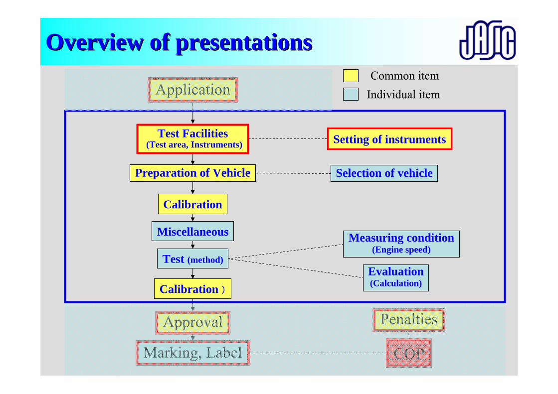
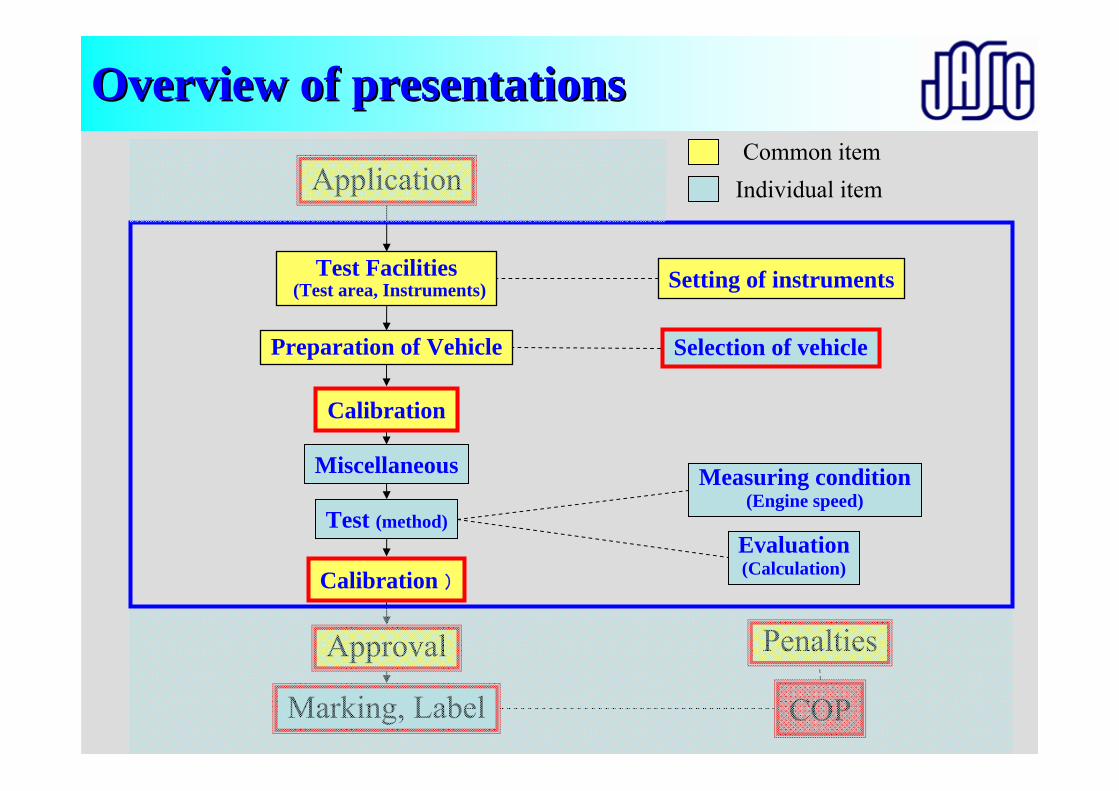
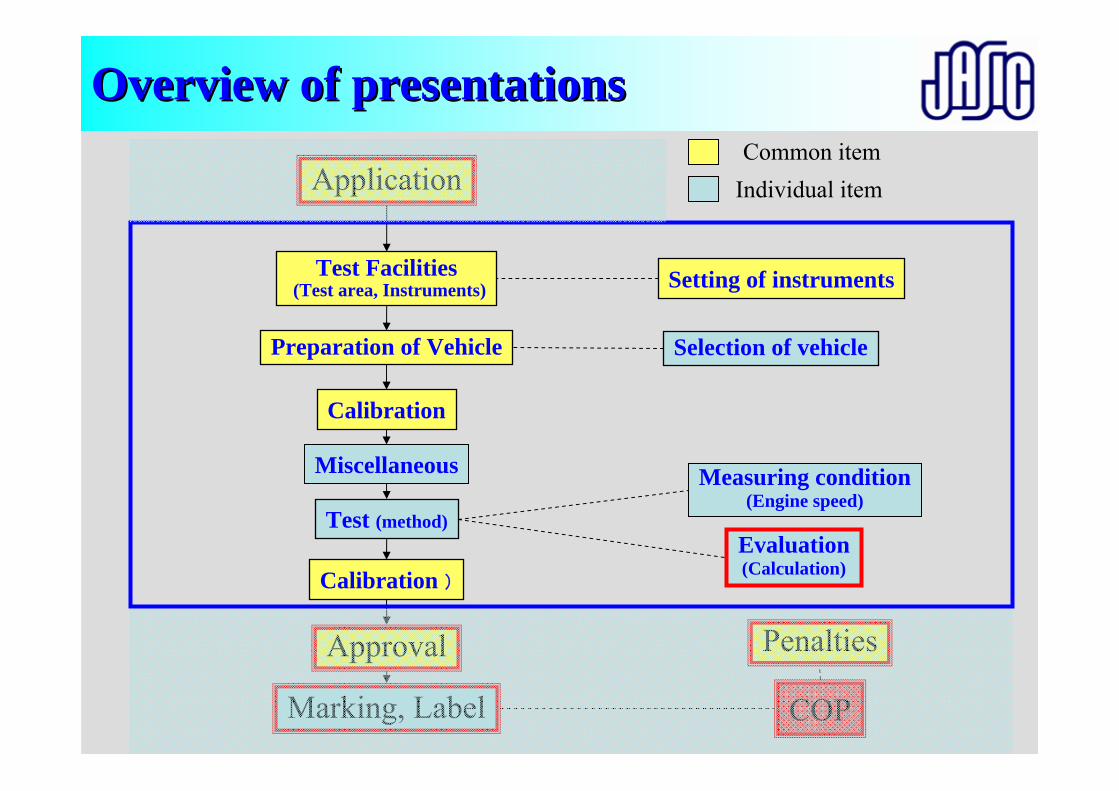
Preparation of Vehicle
Test Facilities(Test area, Instruments)
Miscellaneous
Calibration
Test (method)
Calibration )
Selection of vehicle
Evaluation(Calculation)
Measuring condition(Engine speed)
Setting of instruments
Approval
Marking, Label COP
ApplicationCommon item
Individual item
Penalties
Overview of presentationsOverview of presentations
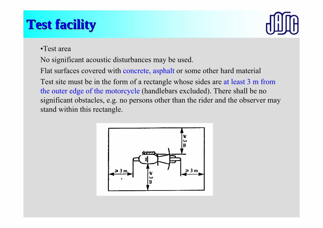
Test facilityTest facility•Test areaNo significant acoustic disturbances may be used. Flat surfaces covered with concrete, asphalt or some other hard materialTest site must be in the form of a rectangle whose sides are at least 3 m from the outer edge of the motorcycle (handlebars excluded). There shall be no significant obstacles, e.g. no persons other than the rider and the observer may stand within this rectangle.
Test facilitiesTest facilities
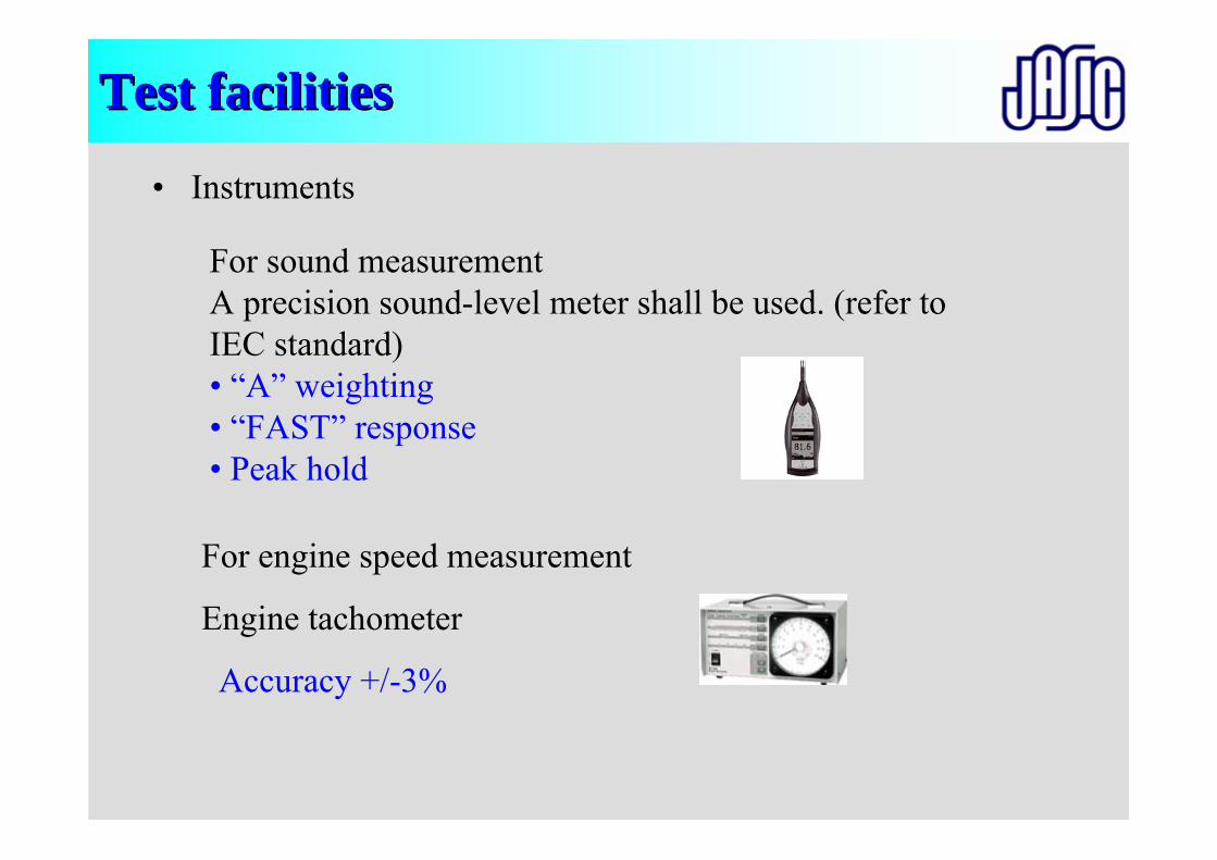
• Instruments
For sound measurementA precision sound-level meter shall be used. (refer to IEC standard)• “A” weighting• “FAST” response• Peak hold
For engine speed measurement
Engine tachometer
Accuracy +/-3%
Preparation of Vehicle
Test Facilities(Test area, Instruments)
Miscellaneous
Calibration
Test (method)
Calibration )
Selection of vehicle
Evaluation(Calculation)
Measuring condition(Engine speed)
Setting of instruments
Approval
Marking, Label COP
ApplicationCommon item
Individual item
Penalties
Overview of presentationsOverview of presentations
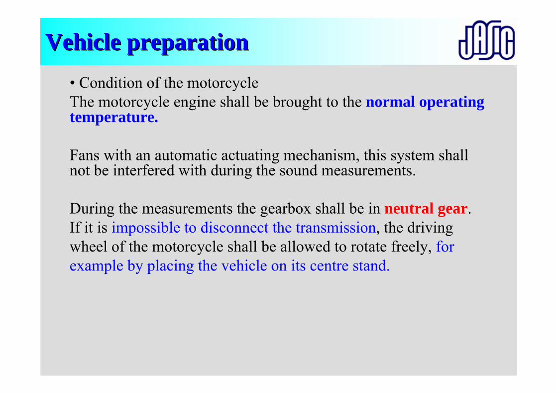
Vehicle preparationVehicle preparation• Condition of the motorcycleThe motorcycle engine shall be brought to the normal operating temperature.
Fans with an automatic actuating mechanism, this system shall not be interfered with during the sound measurements.
During the measurements the gearbox shall be in neutral gear.If it is impossible to disconnect the transmission, the drivingwheel of the motorcycle shall be allowed to rotate freely, forexample by placing the vehicle on its centre stand.
Preparation of Vehicle
Test Facilities(Test area, Instruments)
Miscellaneous
Calibration
Test (method)
Calibration )
Selection of vehicle
Evaluation(Calculation)
Measuring condition(Engine speed)
Setting of instruments
Approval
Marking, Label COP
ApplicationCommon item
Individual item
Penalties
Overview of presentationsOverview of presentations
Selection of vehicle / CalibrationSelection of vehicle / Calibration
• Same as its for measurement of vehicle in motion.
Preparation of Vehicle
Test Facilities(Test area, Instruments)
Miscellaneous
Calibration
Test (method)
Calibration )
Selection of vehicle
Evaluation(Calculation)
Measuring condition(Engine speed)
Setting of instruments
Approval
Marking, Label COP
ApplicationCommon item
Individual item
Penalties
Overview of presentationsOverview of presentations
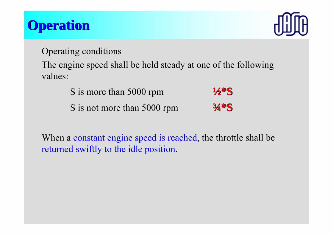
OperationOperation
Operating conditionsThe engine speed shall be held steady at one of the following values:
S is more than 5000 rpm ½½*S*SS is not more than 5000 rpm ¾¾*S*S
When a constant engine speed is reached, the throttle shall be returned swiftly to the idle position.
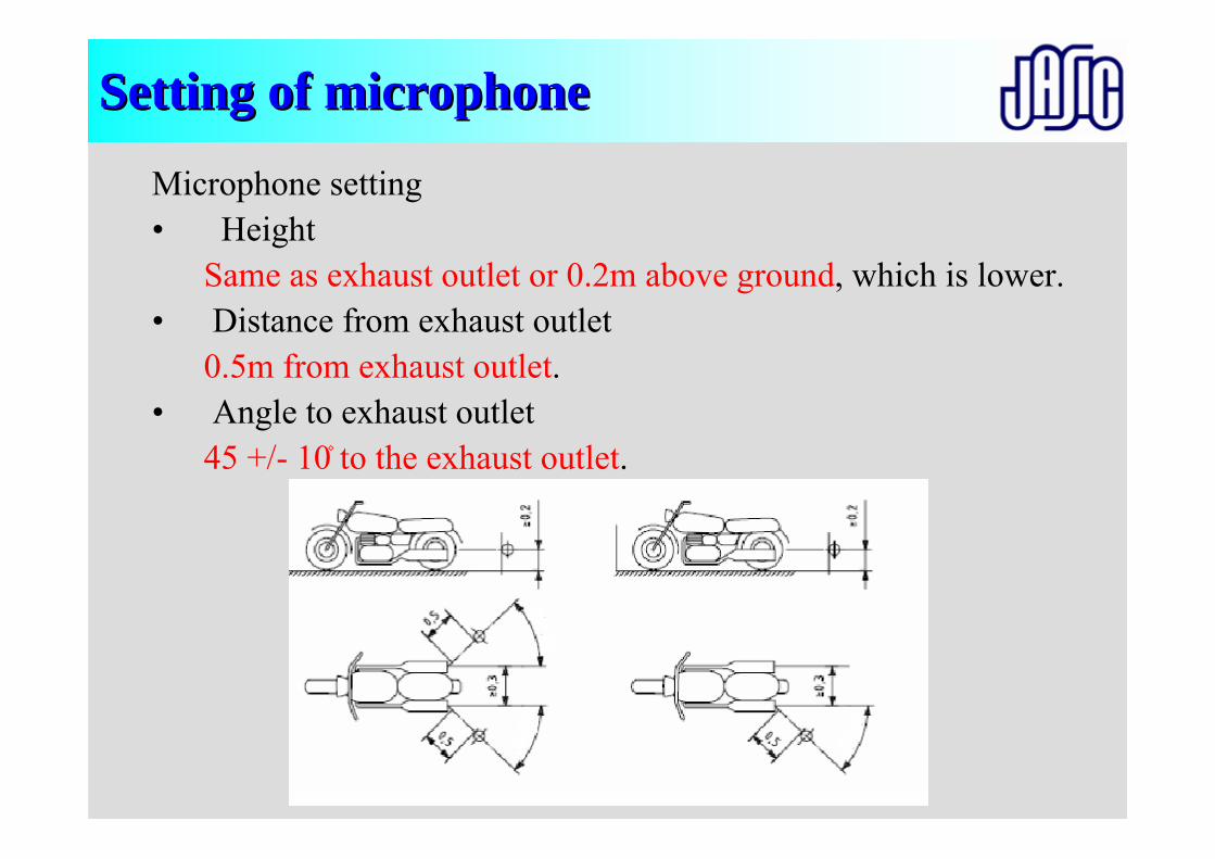
Setting of microphoneSetting of microphone
Microphone setting• Height
Same as exhaust outlet or 0.2m above ground, which is lower.• Distance from exhaust outlet
0.5m from exhaust outlet.• Angle to exhaust outlet
45 +/- 10۫ to the exhaust outlet.
45+/-10°
45+/-10° 45+/-10°
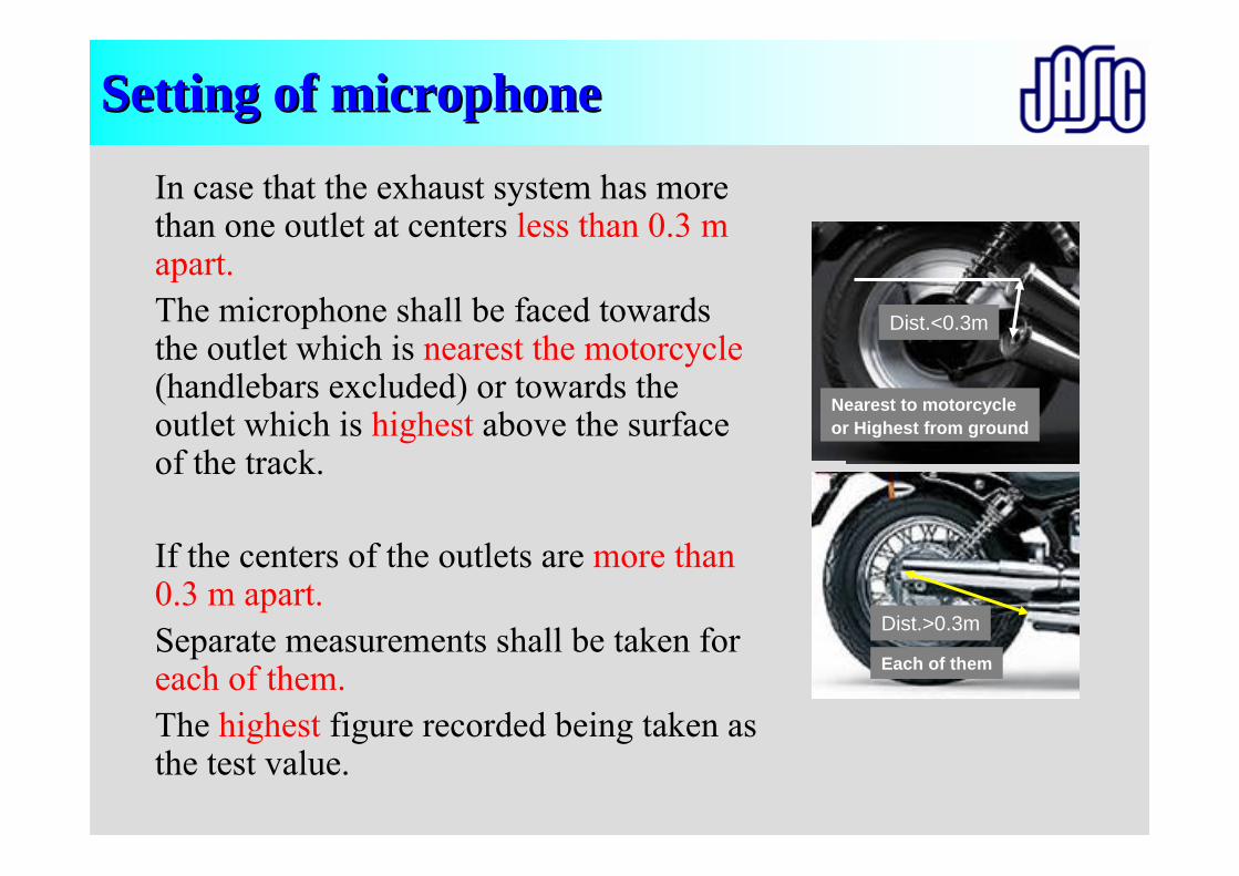
Setting of microphoneSetting of microphone
In case that the exhaust system has more than one outlet at centers less than 0.3 m apart.The microphone shall be faced towards the outlet which is nearest the motorcycle(handlebars excluded) or towards the outlet which is highest above the surface of the track.
If the centers of the outlets are more than 0.3 m apart.Separate measurements shall be taken for each of them. The highest figure recorded being taken as the test value.
Dist.<0.3m
Nearest to motorcycleor Highest from ground
Dist.>0.3m
Each of them
Preparation of Vehicle
Test Facilities(Test area, Instruments)
Miscellaneous
Calibration
Test (method)
Calibration )
Selection of vehicle
Evaluation(Calculation)
Measuring condition(Engine speed)
Setting of instruments
Approval
Marking, Label COP
ApplicationCommon item
Individual item
Penalties
Overview of presentationsOverview of presentations
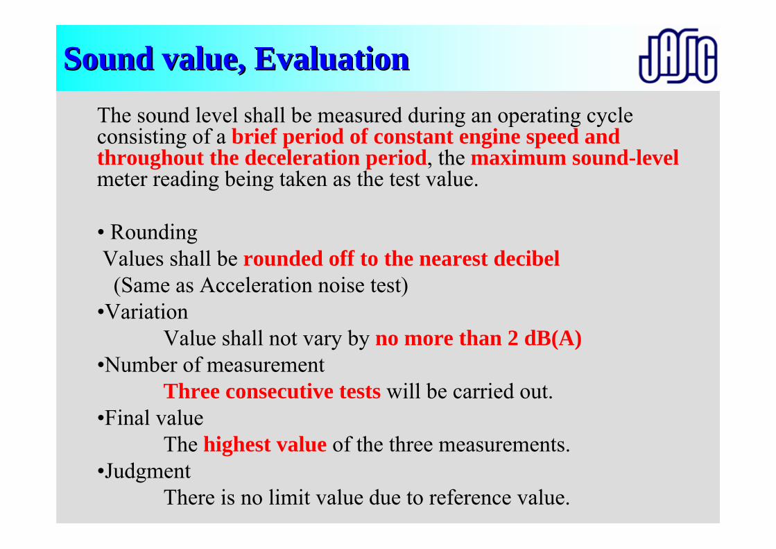
Sound value, EvaluationSound value, EvaluationThe sound level shall be measured during an operating cycle consisting of a brief period of constant engine speed and throughout the deceleration period, the maximum sound-levelmeter reading being taken as the test value.
• RoundingValues shall be rounded off to the nearest decibel(Same as Acceleration noise test)
•VariationValue shall not vary by no more than 2 dB(A)
•Number of measurementThree consecutive tests will be carried out.
•Final valueThe highest value of the three measurements.
•JudgmentThere is no limit value due to reference value.
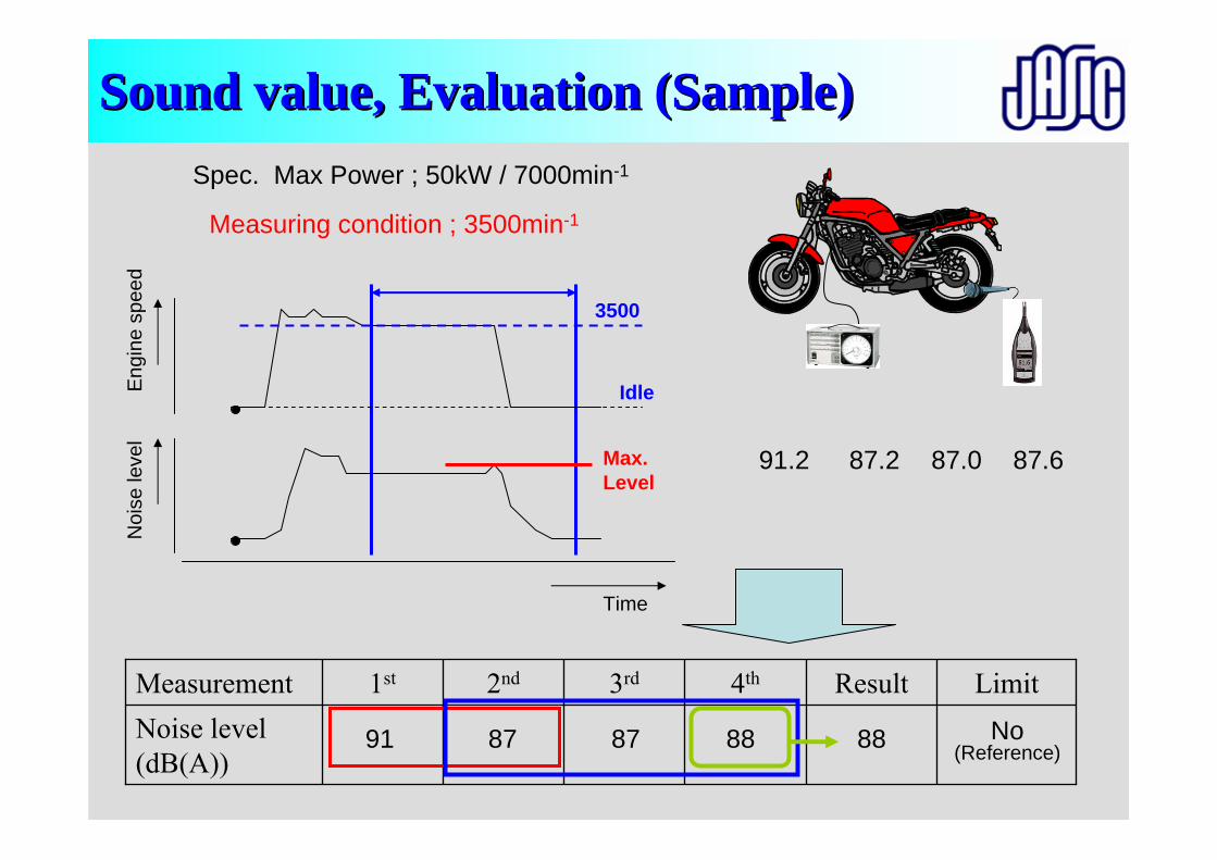
Sound value, Evaluation (Sample)Sound value, Evaluation (Sample)
Noise level (dB(A))
4th3rd2nd1st Result LimitMeasurement
Spec. Max Power ; 50kW / 7000min-1
Measuring condition ; 3500min-1
Time
Eng
ine
spee
dN
oise
leve
l
3500
Idle
Max.Level
91
91.2 87.2 87.0 87.6
87 87 88 88 No(Reference)


Thank you for attentionThank you for attention
www.jasic.org
Test procedure for vehicles having at Test procedure for vehicles having at least four wheelsleast four wheels
R51R51
Y. ShirahashiJASIC Noise-sub committee
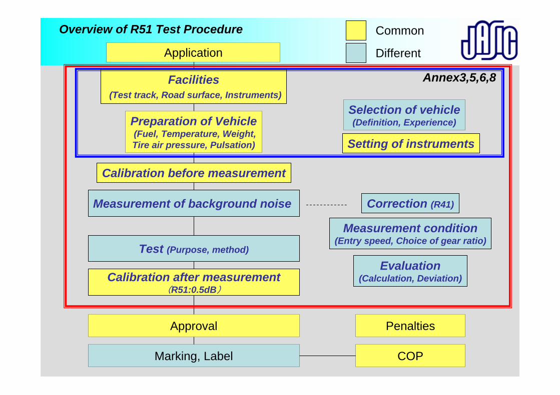
Preparation of Vehicle(Fuel, Temperature, Weight,Tire air pressure, Pulsation)
Facilities(Test track, Road surface, Instruments)
Measurement of background noise
Calibration before measurement
Test (Purpose, method)
Calibration after measurement(R51:0.5dB)
Selection of vehicle(Definition, Experience)
Correction (R41)
Evaluation(Calculation, Deviation)
Measurement condition(Entry speed, Choice of gear ratio)
Setting of instruments
Approval
Marking, Label COP
Application
Common
Different
Penalties
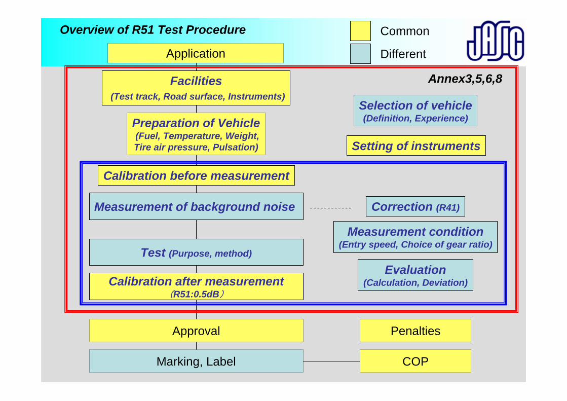
Overview of R51 Test Procedure
Annex3,5,6,8
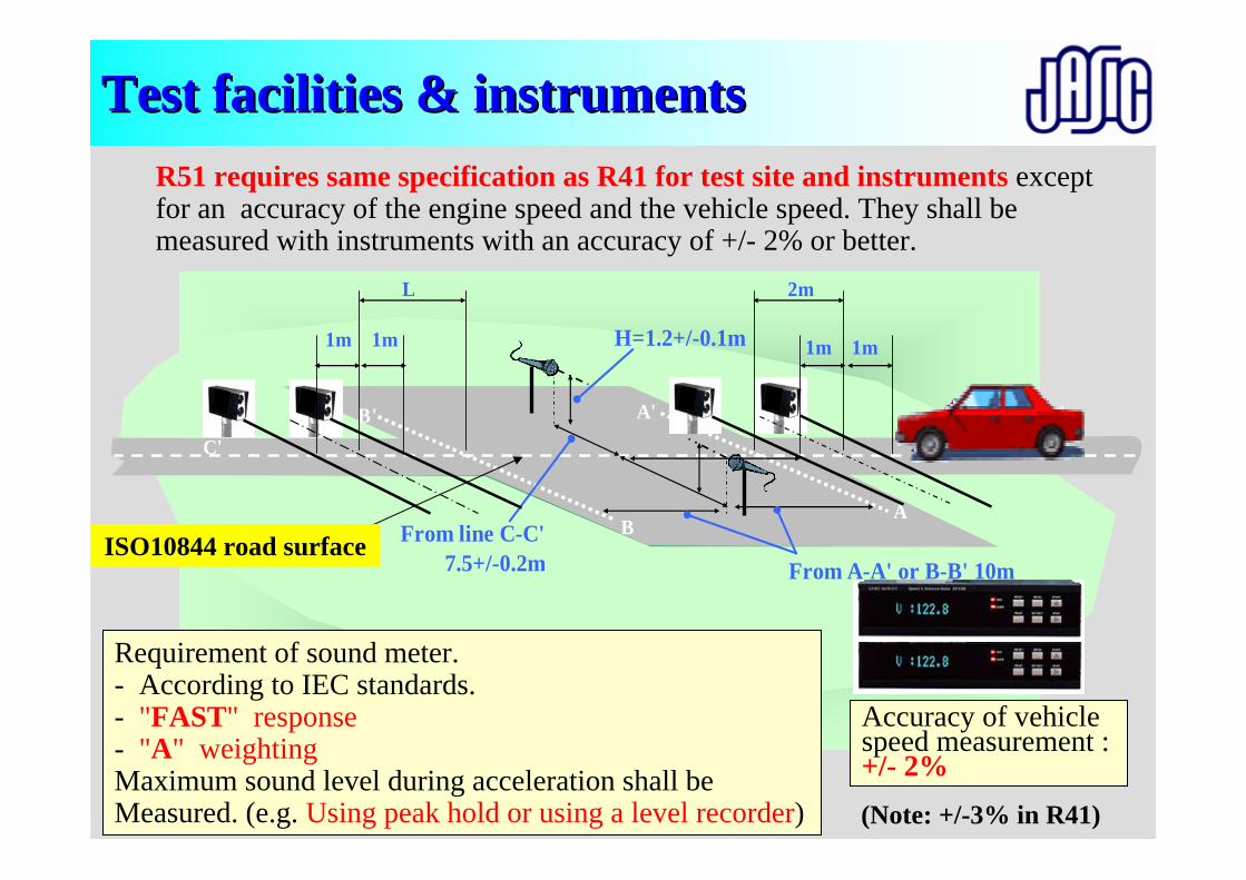
From A-A' or B-B' 10m
H=1.2+/-0.1m
C' C
A
A'
B
B'
1m 1m1m 1m
2m
From line C-C'7.5+/-0.2m
L
Test facilities & instrumentsTest facilities & instrumentsR51 requires same specification as R41 for test site and instruments except for an accuracy of the engine speed and the vehicle speed. They shall be measured with instruments with an accuracy of +/- 2% or better.
Requirement of sound meter.- According to IEC standards.- "FAST" response- "A" weightingMaximum sound level during acceleration shall be Measured. (e.g. Using peak hold or using a level recorder)
ISO10844 road surface
Accuracy of vehicle speed measurement : +/- 2%(Note: +/-3% in R41)
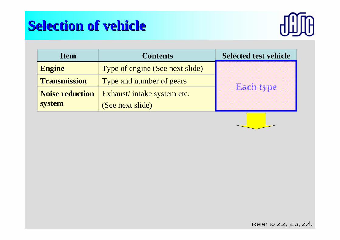
Selection of vehicleSelection of vehicle
No need to be considered for vehicle selection
Not related with noise (i.e. Brakes, Lamps, Name of tire etc.) Other parts
Lowest (Worst case)
Transmission Gear ratio, reduction gear ratio, and tire diameter
Gear ratio
Item
Each typeType and number of gearsTransmissionType of engine (See next slide)Engine
Vehicle mass
Noise reduction system
Unladen mass, curb mass
Exhaust/ intake system etc.(See next slide)
Selected test vehicleContents
Refer to 2.2, 2.3, 2.4.
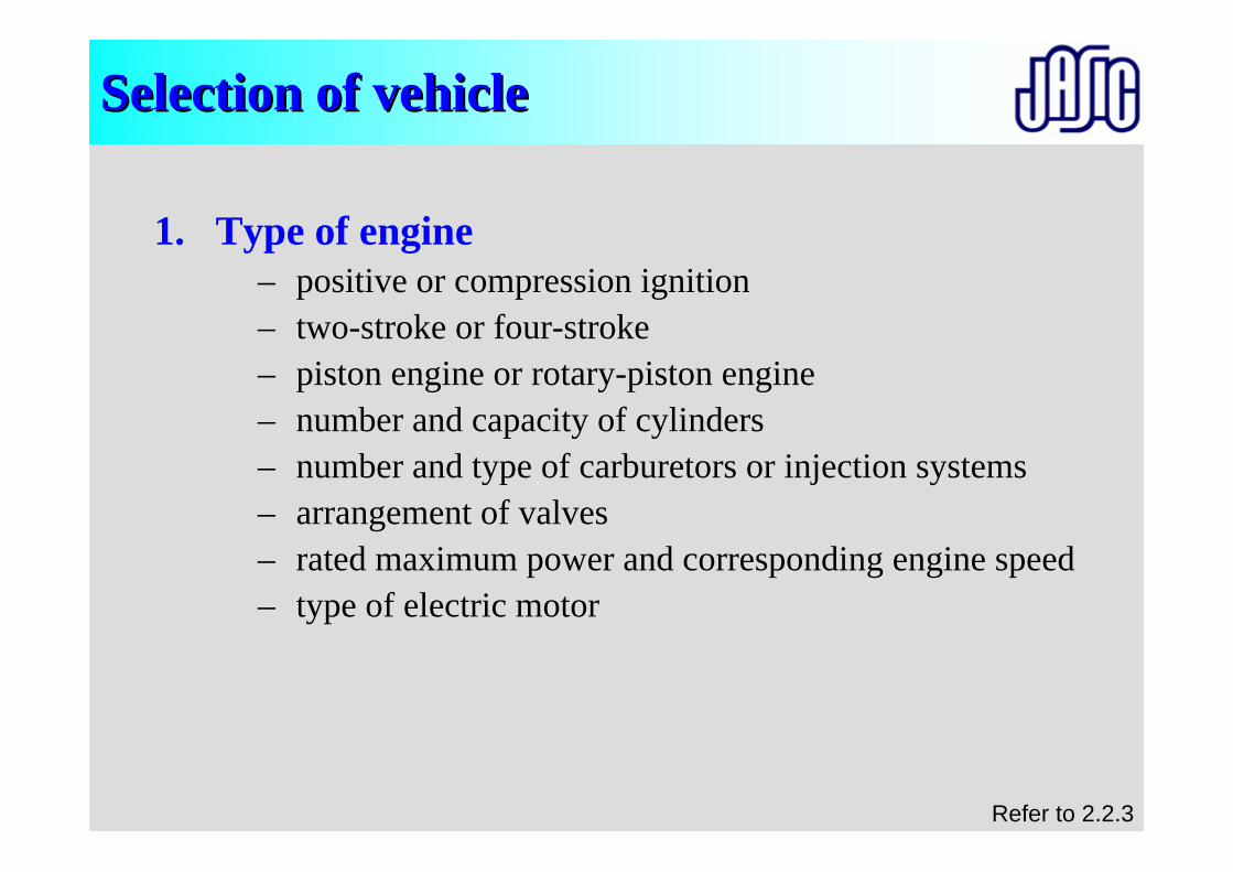
Selection of vehicleSelection of vehicle
1. Type of engine– positive or compression ignition– two-stroke or four-stroke– piston engine or rotary-piston engine– number and capacity of cylinders– number and type of carburetors or injection systems– arrangement of valves– rated maximum power and corresponding engine speed– type of electric motor
Refer to 2.2.3
Selection of vehicleSelection of vehicle
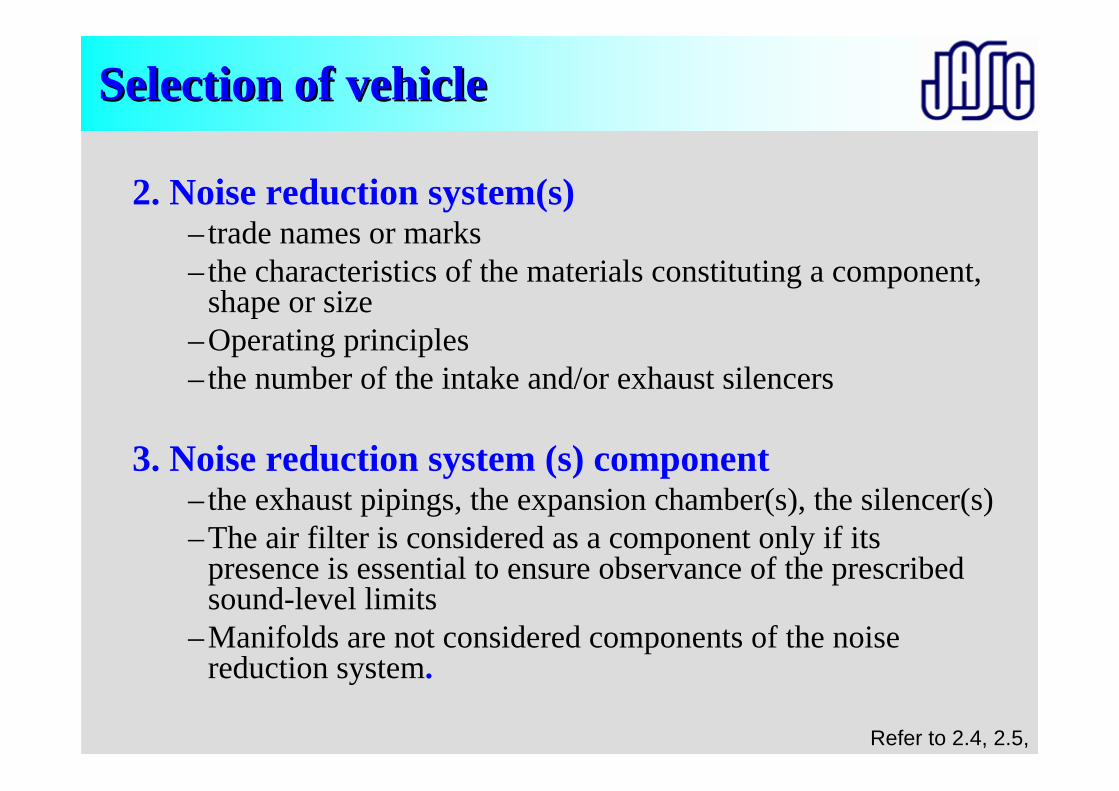
2. Noise reduction system(s)– trade names or marks– the characteristics of the materials constituting a component,
shape or size –Operating principles – the number of the intake and/or exhaust silencers
3. Noise reduction system (s) component– the exhaust pipings, the expansion chamber(s), the silencer(s)–The air filter is considered as a component only if its
presence is essential to ensure observance of the prescribed sound-level limits
–Manifolds are not considered components of the noise reduction system.
Refer to 2.4, 2.5,
PreparationPreparation of test vehiclesof test vehicles
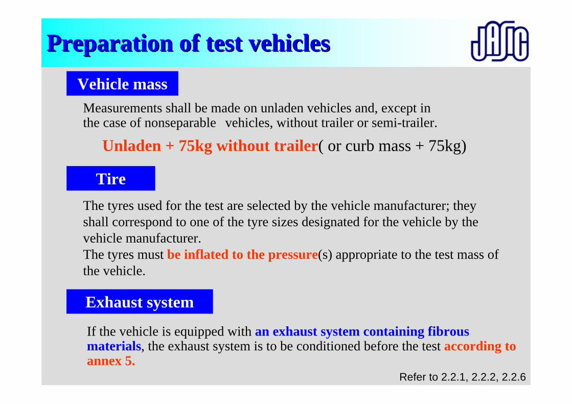
Unladen + 75kg without trailer( or curb mass + 75kg)
Vehicle massMeasurements shall be made on unladen vehicles and, except in the case of nonseparable vehicles, without trailer or semi-trailer.
TireThe tyres used for the test are selected by the vehicle manufacturer; they shall correspond to one of the tyre sizes designated for the vehicle by the vehicle manufacturer.The tyres must be inflated to the pressure(s) appropriate to the test mass of the vehicle.
Exhaust system
If the vehicle is equipped with an exhaust system containing fibrous materials, the exhaust system is to be conditioned before the test according to annex 5.
Refer to 2.2.1, 2.2.2, 2.2.6
• The vehicle shall be brought to its normal operatingconditions - temperatures etc.
• If the vehicle is fitted with more than two-wheel drive, it shall be tested in the drive which is intended for normal road use.
PreparationPreparation of test vehiclesof test vehicles
Before the measurements
Refer to 2.2.3, 2.2.4,
Preparation of Vehicle(Fuel, Temperature, Weight,Tire air pressure, Pulsation)
Facilities(Test track, Road surface, Instruments)
Measurement of background noise
Calibration before measurement
Test (Purpose, method)
Calibration after measurement(R51:0.5dB)
Selection of vehicle(Definition, Experience)
Correction (R41)
Evaluation(Calculation, Deviation)
Measurement condition(Entry speed, Choice of gear ratio)
Setting of instruments
Approval
Marking, Label COP
Application
Common
Different
Penalties
Annex3,5,6,8
Overview of R51 Test Procedure
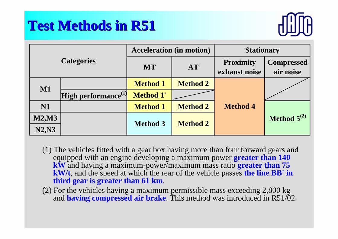
TestTest Methods in R51Methods in R51
(1) The vehicles fitted with a gear box having more than four forward gears and equipped with an engine developing a maximum power greater than 140 kW and having a maximum-power/maximum mass ratio greater than 75 kW/t, and the speed at which the rear of the vehicle passes the line BB' in third gear is greater than 61 km.
(2) For the vehicles having a maximum permissible mass exceeding 2,800 kg and having compressed air brake. This method was introduced in R51/02.
(From R51/02)
MT AT Proximityexhaust noise
Compressedair noise
Method 1 Method 2High performance(1) Method 1'
N1 Method 1 Method 2M2,M3N2,N3
CategoriesStationaryAcceleration (in motion)
Method 2Method 5(2)
Method 3
M1
Method 4
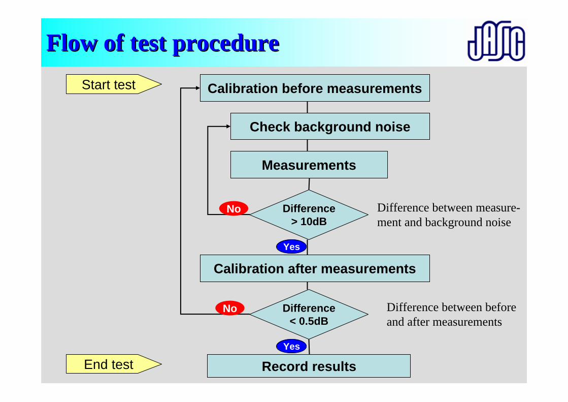
FlowFlow of test procedureof test procedure
Calibration before measurementsStart test
End test
Difference < 0.5dB
Difference > 10dB
Record results
Difference between measure-ment and background noise
Difference between before and after measurements
Check background noise
Measurements
Calibration after measurementsYes
No
No
Yes
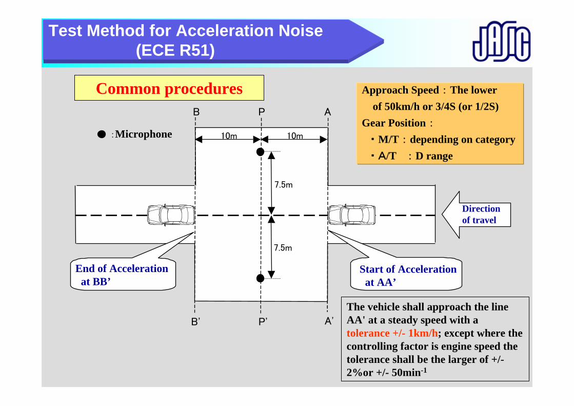
Direction of travel
P
P'
10m10m
7.5m
7.5m
:Microphone
B
B'
A
A'
End of Acceleration at BB’
Start of Accelerationat AA’
Approach Speed : The lower of 50km/h or 3/4S (or 1/2S)
Gear Position :・ M/T : depending on category・ A/T : D range
Test Method for Acceleration Noise (ECE R51)
The vehicle shall approach the line AA' at a steady speed with a tolerance +/- 1km/h; except where the controlling factor is engine speed the tolerance shall be the larger of +/-2%or +/- 50min-1
Common procedures
Test proceduresTest procedures
Vehicle in motion (Sample)
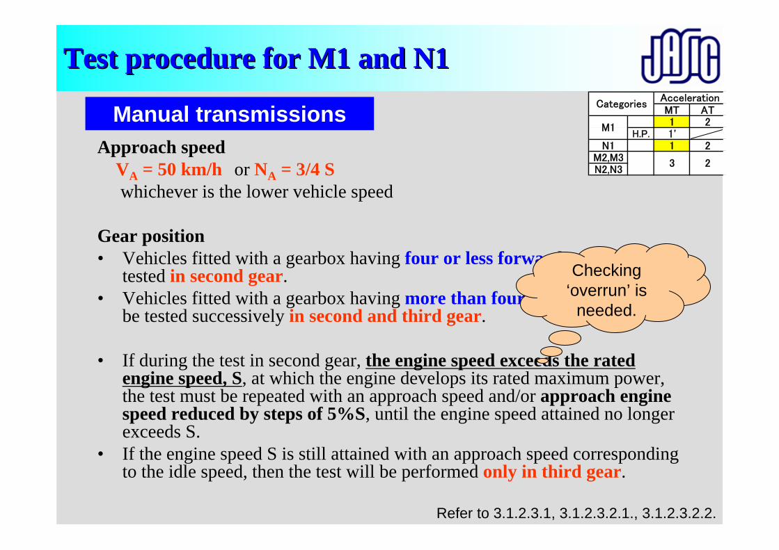
Approach speed VA = 50 km/h or NA = 3/4 Swhichever is the lower vehicle speed
Gear position• Vehicles fitted with a gearbox having four or less forward gears shall be
tested in second gear.• Vehicles fitted with a gearbox having more than four forward gears shall
be tested successively in second and third gear.
• If during the test in second gear, the engine speed exceeds the rated engine speed, S, at which the engine develops its rated maximum power, the test must be repeated with an approach speed and/or approach engine speed reduced by steps of 5%S, until the engine speed attained no longer exceeds S.
• If the engine speed S is still attained with an approach speed corresponding to the idle speed, then the test will be performed only in third gear.
Manual transmissions
Refer to 3.1.2.3.1, 3.1.2.3.2.1., 3.1.2.3.2.2.
Checking ‘overrun’ is
needed.
Test procedure for Test procedure for M1M1 and N1and N1MT AT1 2
H.P. 1'N1 1 2
M2,M3N2,N3
CategoriesAcceleration
M1
3 2
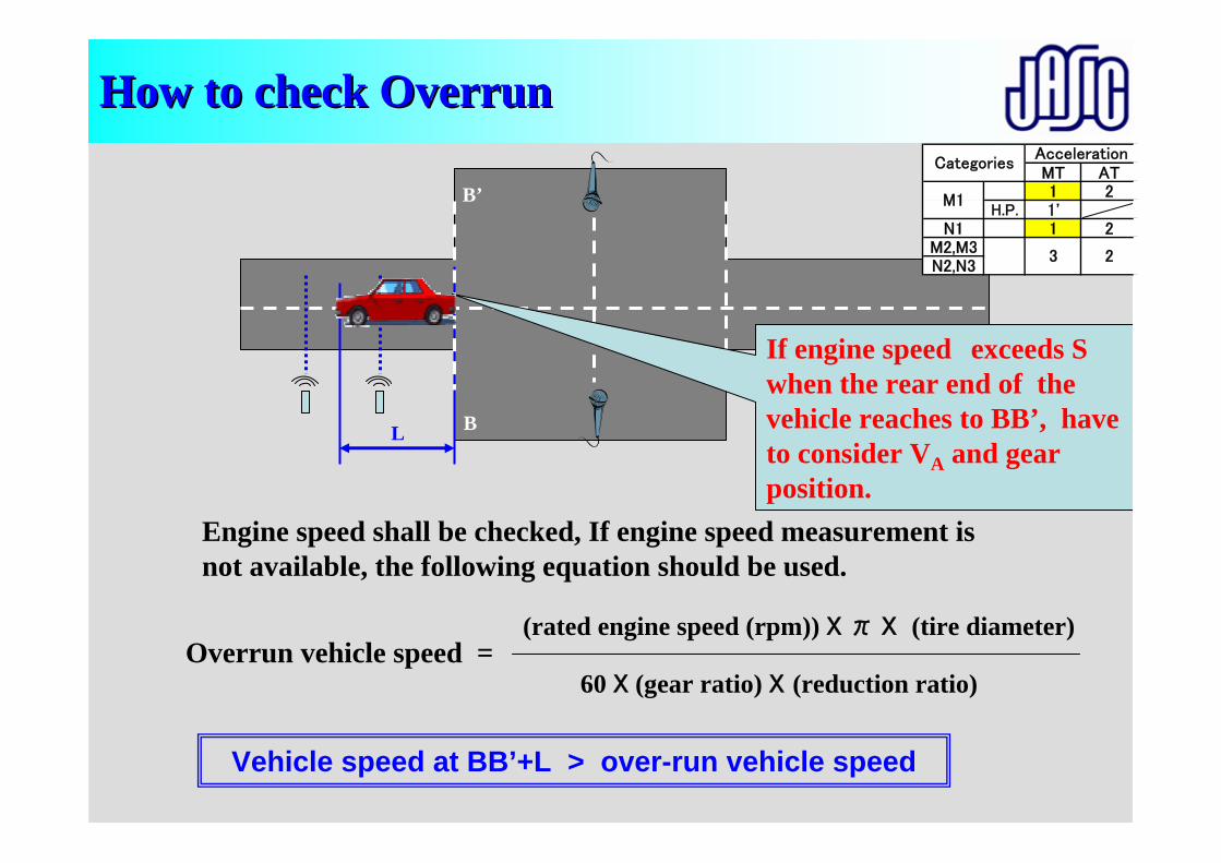
How to check OverrunHow to check Overrun
Vehicle speed at BB’+L > over-run vehicle speed
Engine speed shall be checked, If engine speed measurement is not available, the following equation should be used.
Overrun vehicle speed =(rated engine speed (rpm)) X π X (tire diameter)
60 X (gear ratio) X (reduction ratio)
B
B’
L
If engine speed exceeds S when the rear end of the vehicle reaches to BB’, have to consider VA and gear position.
MT AT1 2
H.P. 1'N1 1 2
M2,M3N2,N3
CategoriesAcceleration
M1
3 2
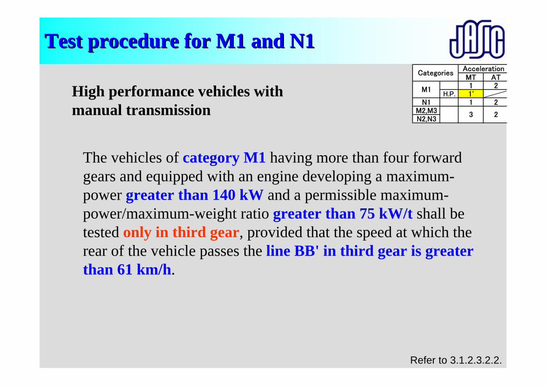
Test procedure for Test procedure for M1M1 and N1and N1
The vehicles of category M1 having more than four forward gears and equipped with an engine developing a maximum-power greater than 140 kW and a permissible maximum-power/maximum-weight ratio greater than 75 kW/t shall be tested only in third gear, provided that the speed at which the rear of the vehicle passes the line BB' in third gear is greater than 61 km/h.
High performance vehicles with manual transmission
Refer to 3.1.2.3.2.2.
MT AT1 2
H.P. 1'N1 1 2
M2,M3N2,N3
CategoriesAcceleration
M1
3 2

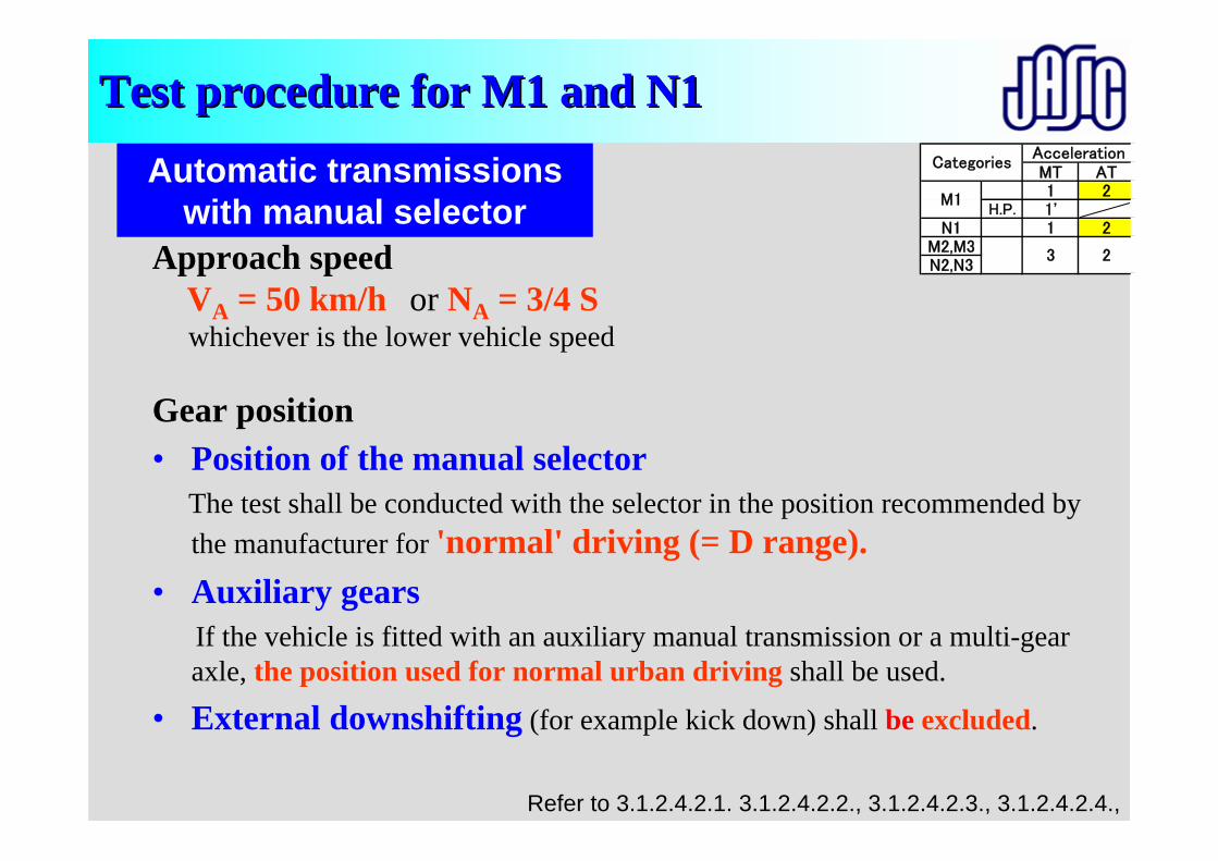
Approach speed VA = 50 km/h or NA = 3/4 Swhichever is the lower vehicle speed
Gear position• Position of the manual selector
The test shall be conducted with the selector in the position recommended by the manufacturer for 'normal' driving (= D range).
• Auxiliary gearsIf the vehicle is fitted with an auxiliary manual transmission or a multi-gear axle, the position used for normal urban driving shall be used.
• External downshifting (for example kick down) shall be excluded.
Test procedure for Test procedure for M1M1 and N1and N1
Automatic transmissions with manual selector
Refer to 3.1.2.4.2.1. 3.1.2.4.2.2., 3.1.2.4.2.3., 3.1.2.4.2.4.,
MT AT1 2
H.P. 1'N1 1 2
M2,M3N2,N3
CategoriesAcceleration
M1
3 2
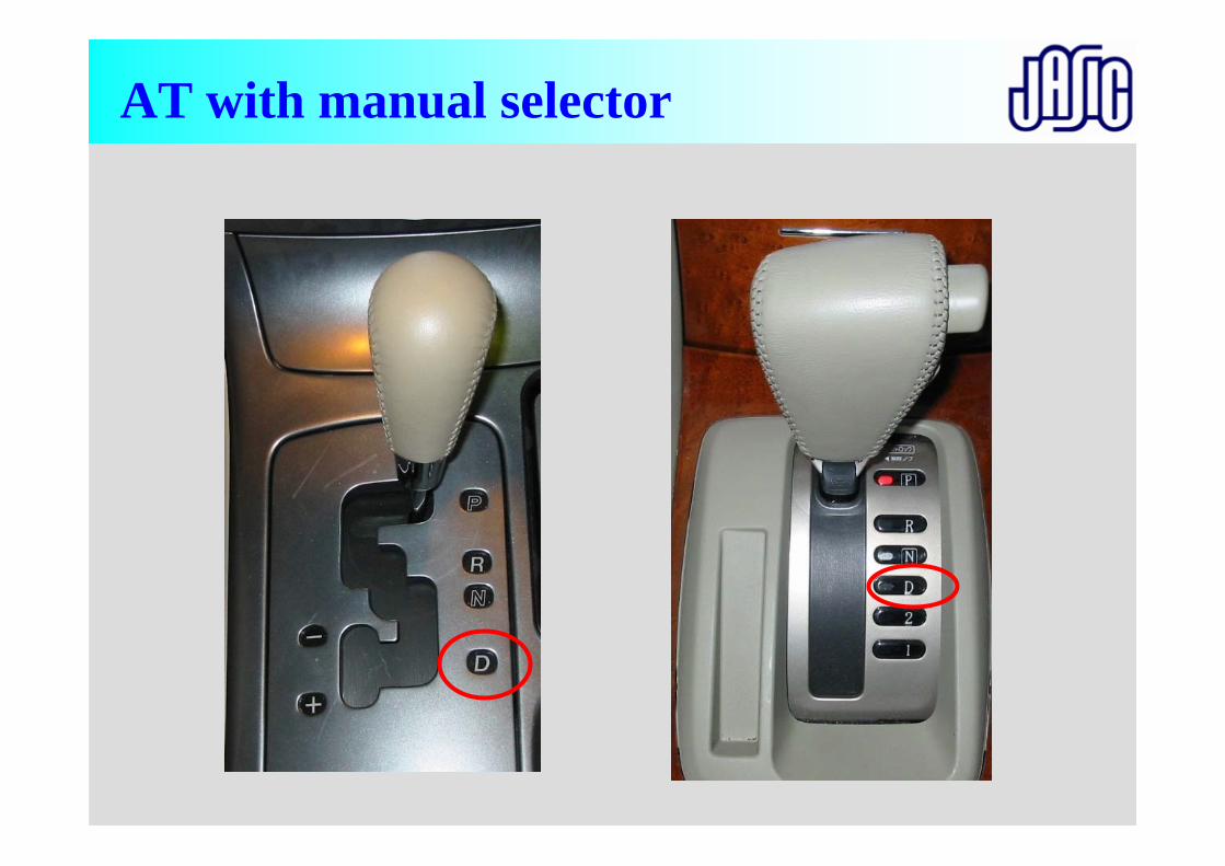
AT with manual selector
Approach speed VA = 50 km/h or NA = 3/4 Swhichever is the lower vehicle speed
Gear position• Position of the manual selector
The test shall be conducted with the selector in the position recommended by the manufacturer for 'normal' driving (= D range).
• Auxiliary gearsIf the vehicle is fitted with an auxiliary manual transmission or a multi-gear axle, the position used for normal urban driving shall be used.
• External downshifting (for example kick down) shall be excluded.
Test procedure for Test procedure for M1M1 and N1and N1
Automatic transmissions with manual selector
Refer to 3.1.2.4.2.1. 3.1.2.4.2.2., 3.1.2.4.2.3., 3.1.2.4.2.4.,
MT AT1 2
H.P. 1'N1 1 2
M2,M3N2,N3
CategoriesAcceleration
M1
3 2
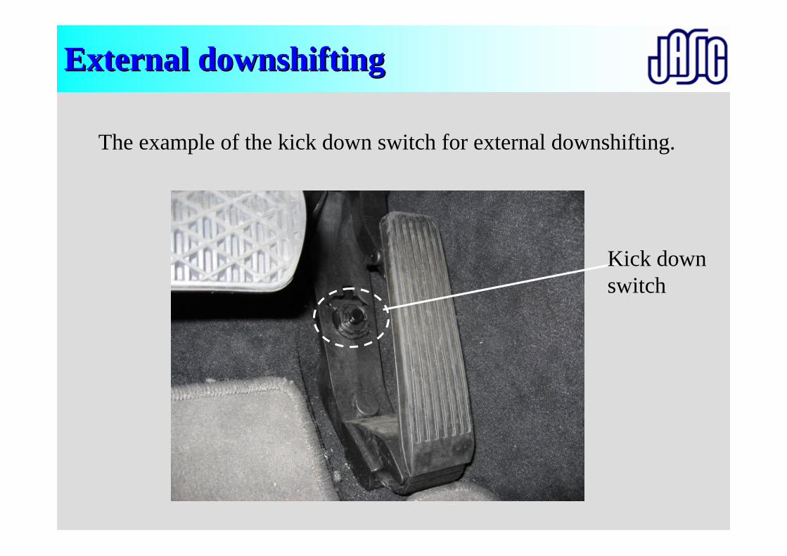
External downshiftingExternal downshifting
The example of the kick down switch for external downshifting.
Kick down switch
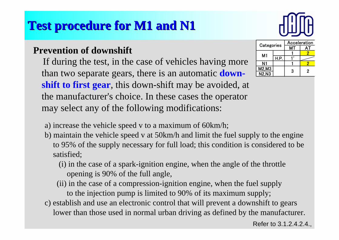
Prevention of downshiftIf during the test, in the case of vehicles having more than two separate gears, there is an automatic down-shift to first gear, this down-shift may be avoided, at the manufacturer's choice. In these cases the operator may select any of the following modifications:
Test procedure for Test procedure for M1M1 and N1and N1
Refer to 3.1.2.4.2.4.,
a) increase the vehicle speed v to a maximum of 60km/h;b) maintain the vehicle speed v at 50km/h and limit the fuel supply to the engine
to 95% of the supply necessary for full load; this condition is considered to be satisfied;
(i) in the case of a spark-ignition engine, when the angle of the throttle opening is 90% of the full angle,
(ii) in the case of a compression-ignition engine, when the fuel supply to the injection pump is limited to 90% of its maximum supply;
c) establish and use an electronic control that will prevent a downshift to gears lower than those used in normal urban driving as defined by the manufacturer.
MT AT1 2
H.P. 1'N1 1 2
M2,M3N2,N3
CategoriesAcceleration
M1
3 2
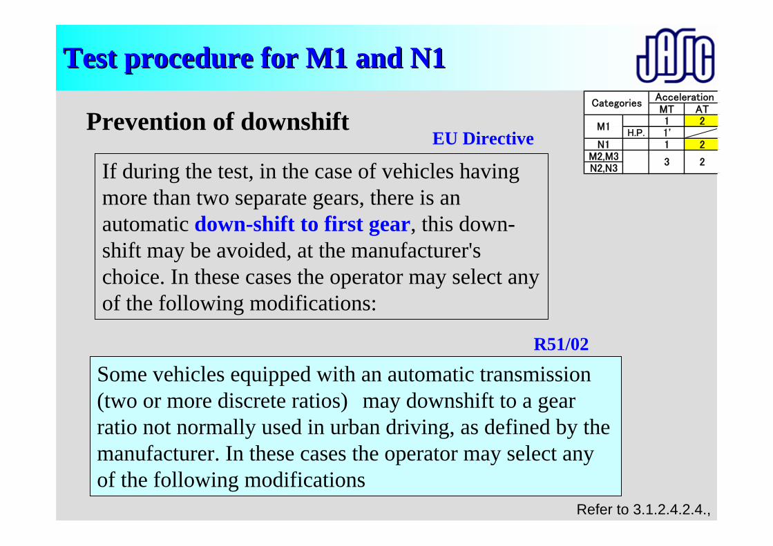
Prevention of downshift
Test procedure for Test procedure for M1M1 and N1and N1
Refer to 3.1.2.4.2.4.,
MT AT1 2
H.P. 1'N1 1 2
M2,M3N2,N3
CategoriesAcceleration
M1
3 2
Some vehicles equipped with an automatic transmission (two or more discrete ratios) may downshift to a gear ratio not normally used in urban driving, as defined by the manufacturer. In these cases the operator may select any of the following modifications
If during the test, in the case of vehicles having more than two separate gears, there is an automatic down-shift to first gear, this down-shift may be avoided, at the manufacturer's choice. In these cases the operator may select any of the following modifications:
EU Directive
R51/02
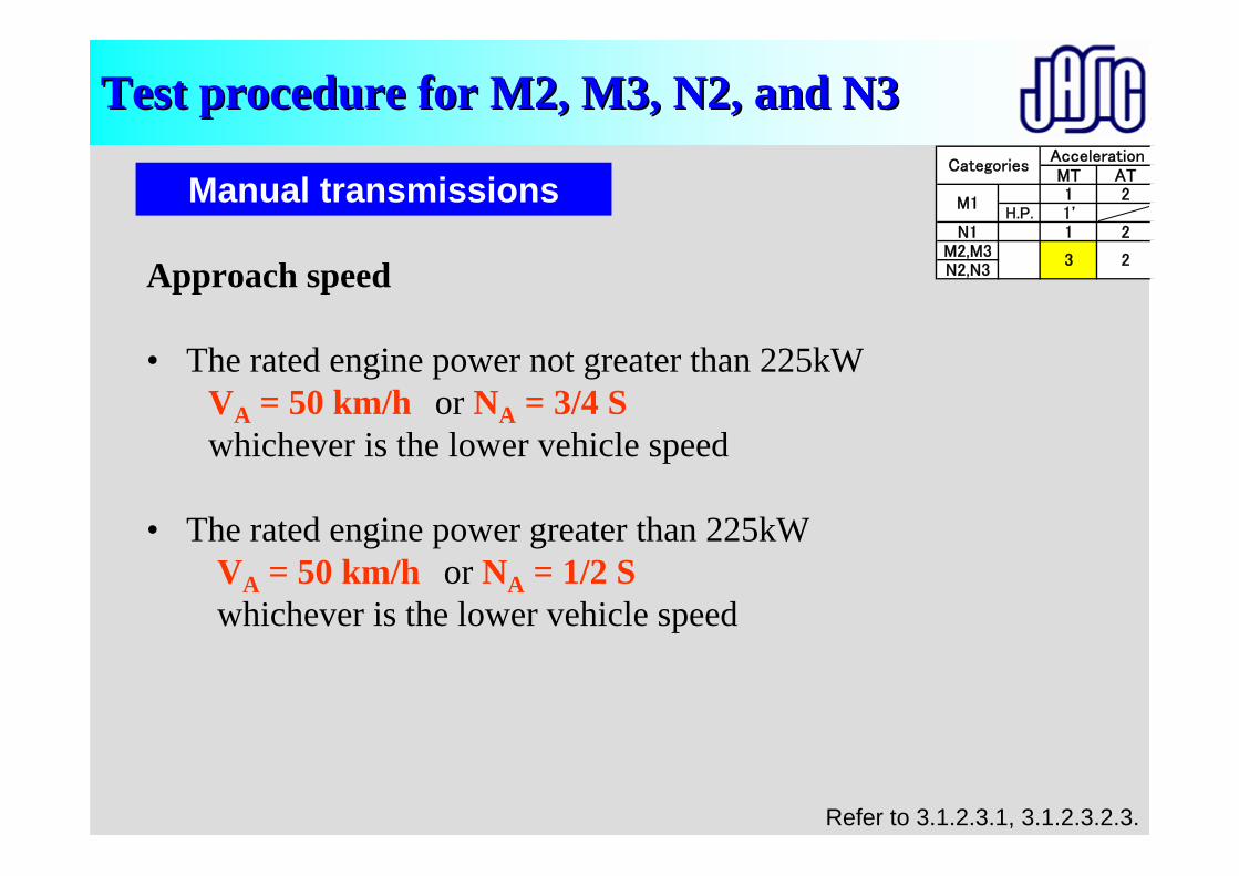
Test procedure for Test procedure for MM2, M3, N2, and N32, M3, N2, and N3
Manual transmissions
Refer to 3.1.2.3.1, 3.1.2.3.2.3.
Approach speed
• The rated engine power not greater than 225kWVA = 50 km/h or NA = 3/4 Swhichever is the lower vehicle speed
• The rated engine power greater than 225kWVA = 50 km/h or NA = 1/2 Swhichever is the lower vehicle speed
MT AT1 2
H.P. 1'N1 1 2
M2,M3N2,N3
CategoriesAcceleration
M1
3 2
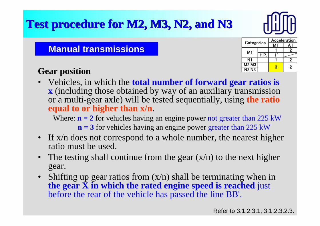
Test procedure for Test procedure for MM2, M3, N2, and N32, M3, N2, and N3
Manual transmissions
Refer to 3.1.2.3.1, 3.1.2.3.2.3.
Gear position• Vehicles, in which the total number of forward gear ratios is
x (including those obtained by way of an auxiliary transmission or a multi-gear axle) will be tested sequentially, using the ratio equal to or higher than x/n.
Where: n = 2 for vehicles having an engine power not greater than 225 kWn = 3 for vehicles having an engine power greater than 225 kW
• If x/n does not correspond to a whole number, the nearest higherratio must be used.
• The testing shall continue from the gear (x/n) to the next higher gear.
• Shifting up gear ratios from (x/n) shall be terminating when in the gear X in which the rated engine speed is reached just before the rear of the vehicle has passed the line BB'.
MT AT1 2
H.P. 1'N1 1 2
M2,M3N2,N3
CategoriesAcceleration
M1
3 2
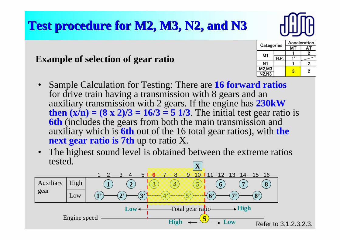
Test procedure for Test procedure for MM2, M3, N2, and N32, M3, N2, and N3
• Sample Calculation for Testing: There are 16 forward ratiosfor drive train having a transmission with 8 gears and an auxiliary transmission with 2 gears. If the engine has 230kW then (x/n) = (8 x 2)/3 = 16/3 = 5 1/3. The initial test gear ratio is6th (includes the gears from both the main transmission and auxiliary which is 6th out of the 16 total gear ratios), with the next gear ratio is 7th up to ratio X.
• The highest sound level is obtained between the extreme ratios tested.
Example of selection of gear ratio
Refer to 3.1.2.3.2.3.
MT AT1 2
H.P. 1'N1 1 2
M2,M3N2,N3
CategoriesAcceleration
M1
3 2
1 2 3 4 5 6 7 8
Total gear ratioEngine speed
1’ 2’ 3’ 4’ 5’ 6’ 7’ 8’
HighLowS LowHigh
Low
HighAuxiliary gear
1 2 3 4 5 6 7 8 9 10 11 12 13 14 15 16X
Test procedure for Test procedure for MM2, M3, N2, and N32, M3, N2, and N3
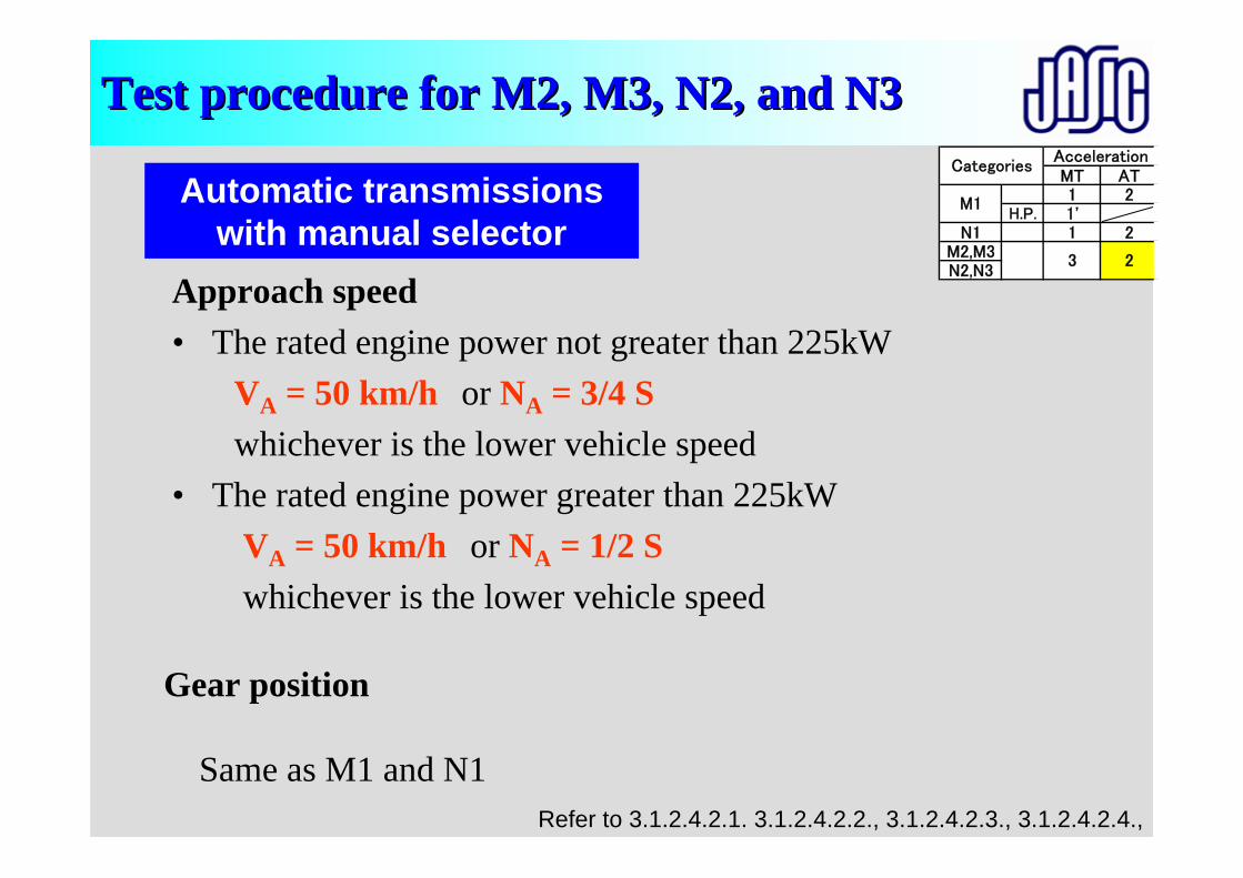
Automatic transmissions with manual selector
Refer to 3.1.2.4.2.1. 3.1.2.4.2.2., 3.1.2.4.2.3., 3.1.2.4.2.4.,
Gear position
Same as M1 and N1
Approach speed • The rated engine power not greater than 225kW
VA = 50 km/h or NA = 3/4 Swhichever is the lower vehicle speed
• The rated engine power greater than 225kWVA = 50 km/h or NA = 1/2 Swhichever is the lower vehicle speed
MT AT1 2
H.P. 1'N1 1 2
M2,M3N2,N3
CategoriesAcceleration
M1
3 2
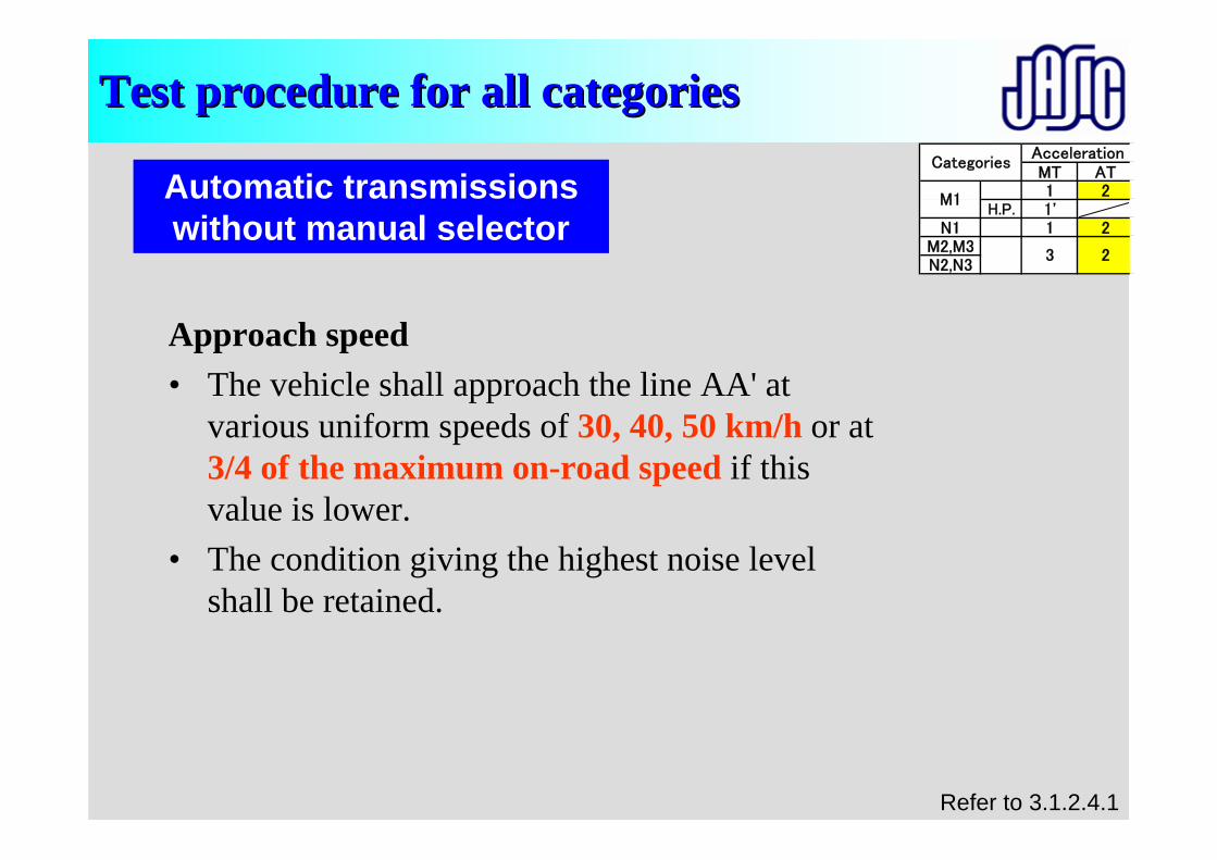
Test procedure for all categoriesTest procedure for all categories
Approach speed• The vehicle shall approach the line AA' at
various uniform speeds of 30, 40, 50 km/h or at 3/4 of the maximum on-road speed if this value is lower.
• The condition giving the highest noise level shall be retained.
Automatic transmissions without manual selector
Refer to 3.1.2.4.1
MT AT1 2
H.P. 1'N1 1 2
M2,M3N2,N3
CategoriesAcceleration
M1
3 2
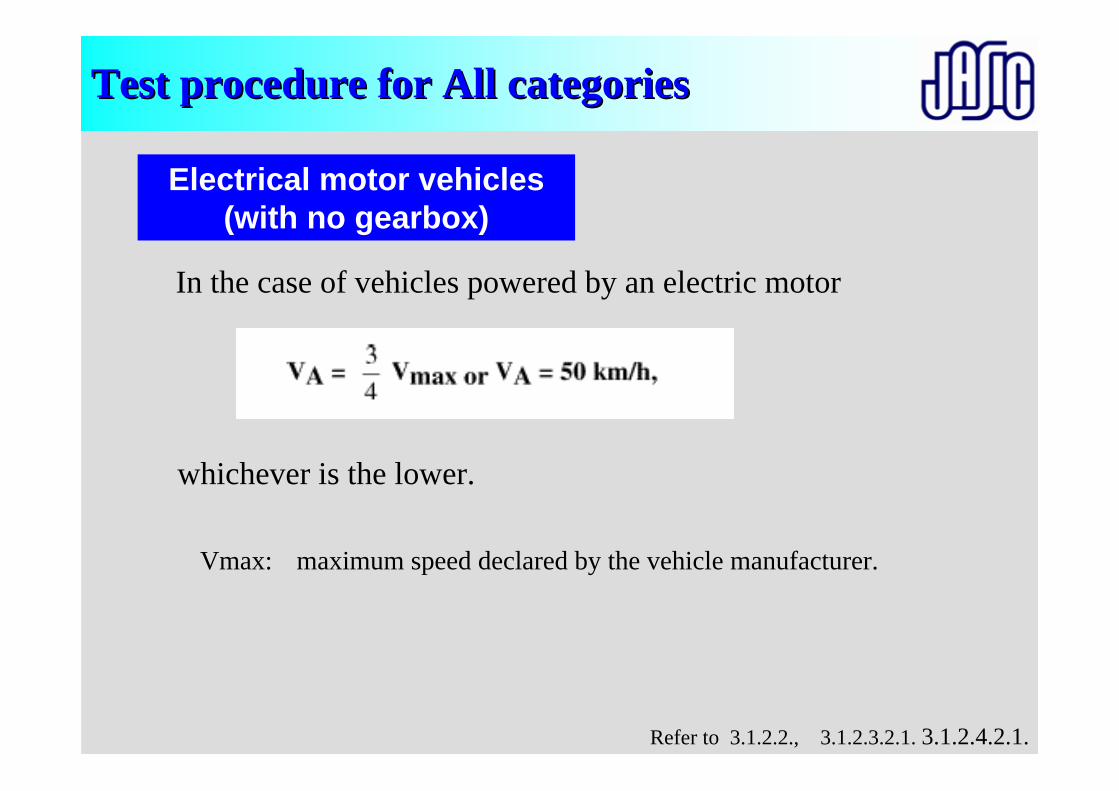
Test procedure for All categoriesTest procedure for All categories
In the case of vehicles powered by an electric motor
Electrical motor vehicles(with no gearbox)
whichever is the lower.
Refer to 3.1.2.2., 3.1.2.3.2.1. 3.1.2.4.2.1.
Vmax: maximum speed declared by the vehicle manufacturer.
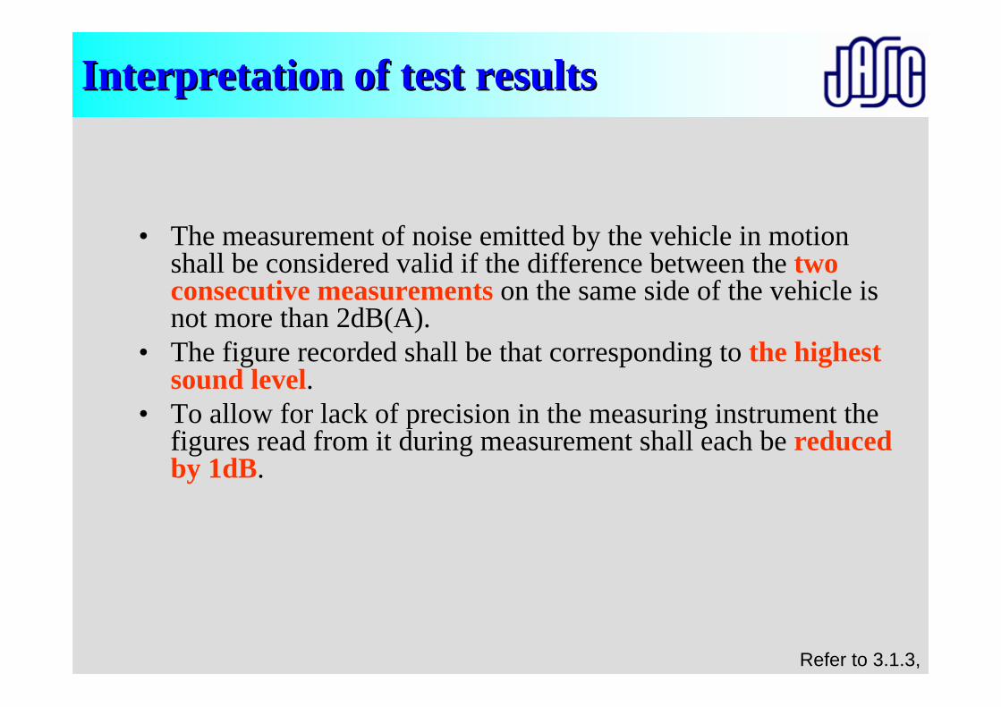
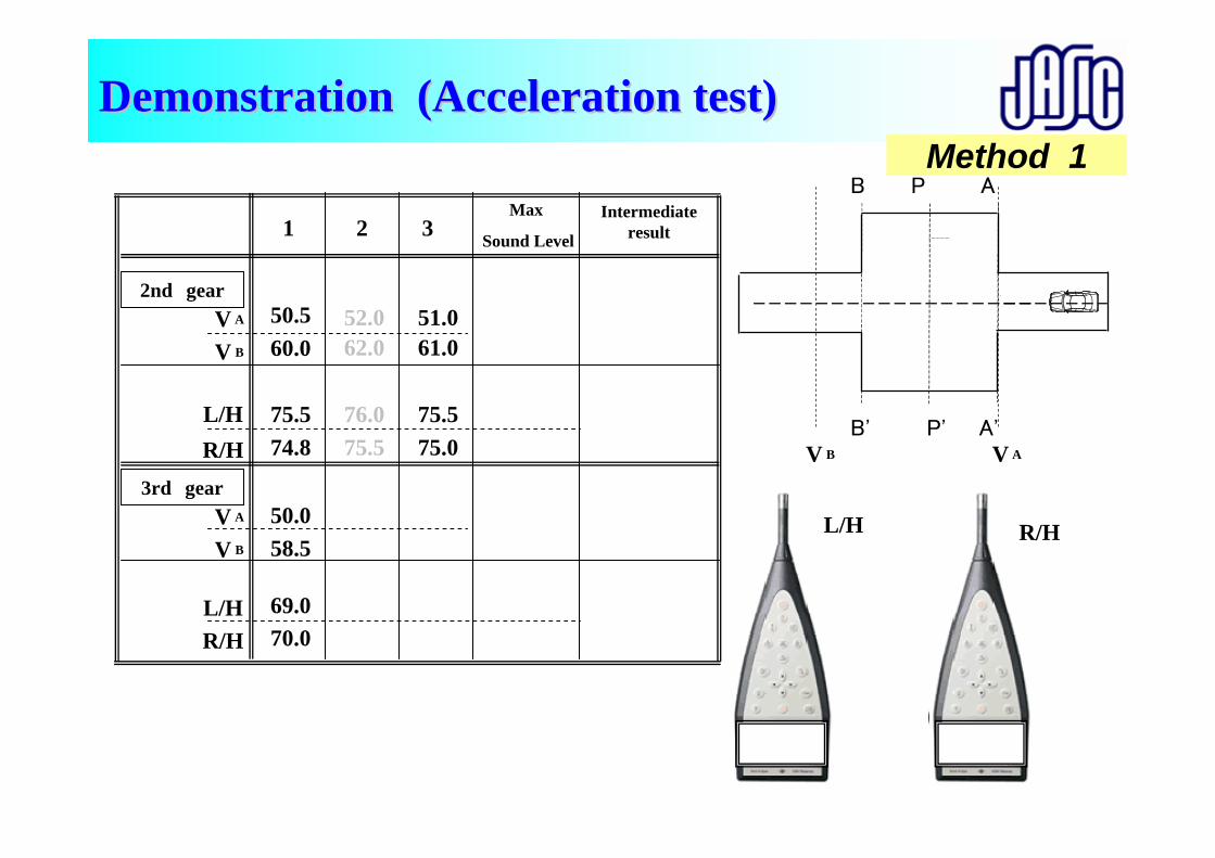
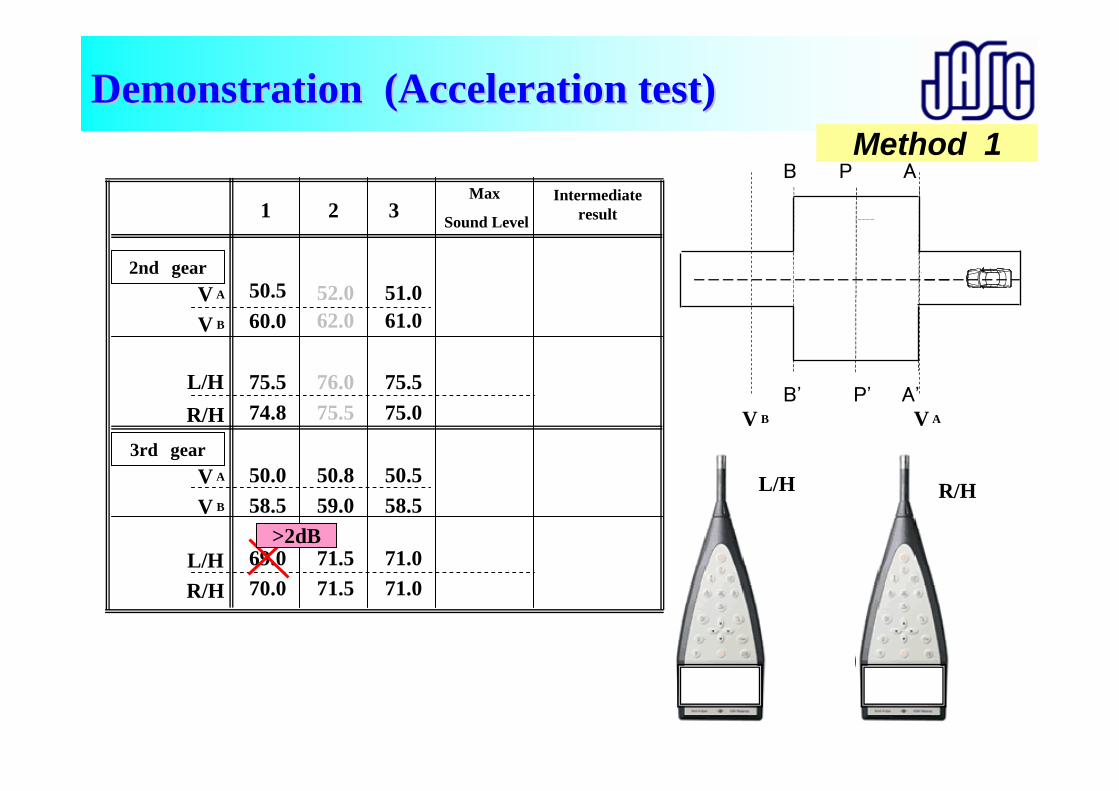
Interpretation of test resultsInterpretation of test results
• The measurement of noise emitted by the vehicle in motion shall be considered valid if the difference between the two consecutive measurements on the same side of the vehicle is not more than 2dB(A).
• The figure recorded shall be that corresponding to the highest sound level.
• To allow for lack of precision in the measuring instrument the figures read from it during measurement shall each be reduced by 1dB.
Refer to 3.1.3,
P' V AV B
P AB
L/H R/H
B' A'
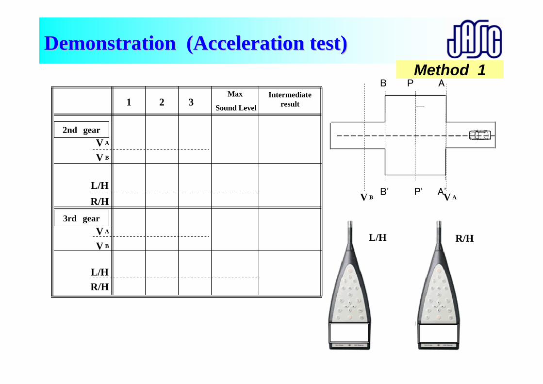
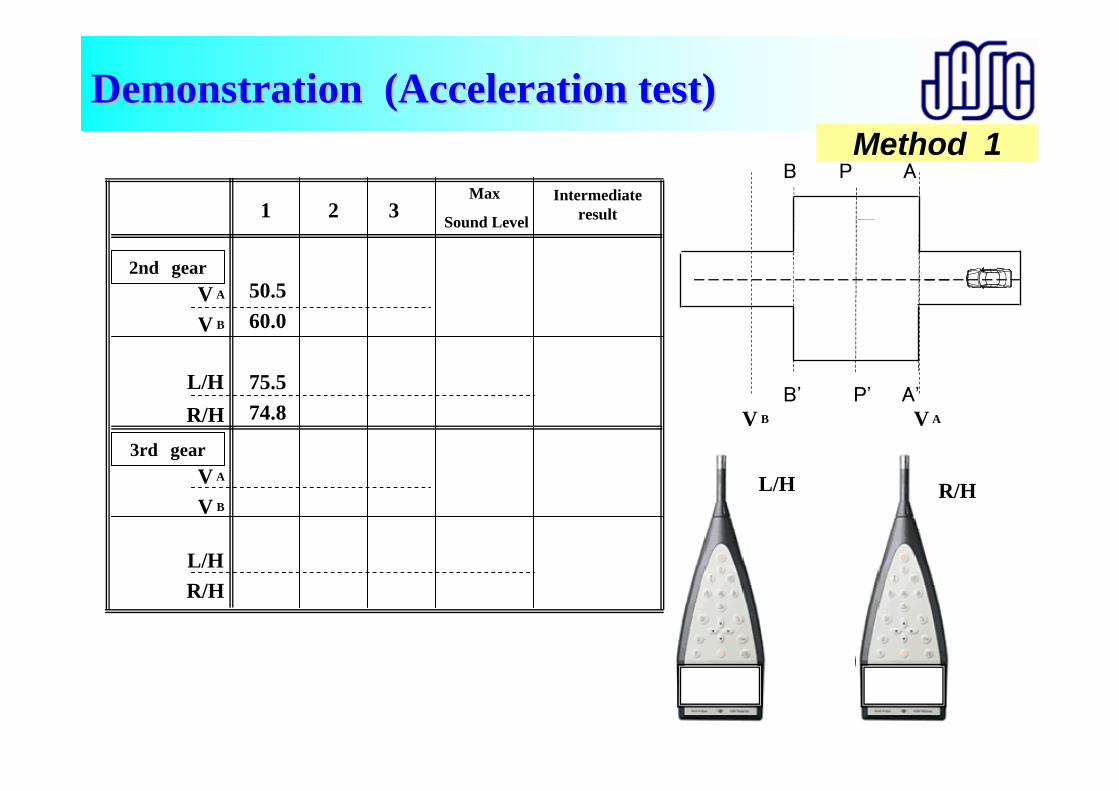
Demonstration (Acceleration test)Demonstration (Acceleration test)
-1 -1
50.560.0
76.5 75.8
1 2 3Max
Sound Level
Intermediate result
2nd gearV A
V B
L/HR/H
3rd gearV A
V B
L/HR/H
50.560.0
75.574.8
50.058.5
69.070.0
52.062.0
76.075.5
50.859.0
71.571.55
51.061.0
75.575.0
50.558.5
71.071.0
76.576.0
72.572.5
76.5
72.5
Method 1
P'V AV B
P AB
L/H
B' A'
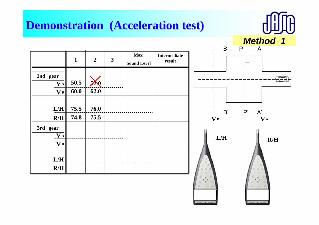
Demonstration (Acceleration test)Demonstration (Acceleration test)
-1 -1
52.062.0
77.0 76.5
R/H
1 2 3Max
Sound Level
Intermediate result
2nd gearV A
V B
L/HR/H
3rd gearV A
V B
L/HR/H
50.560.0
75.574.8
50.058.5
69.070.0
52.062.0
76.075.5
50.859.0
71.571.55
51.061.0
75.575.0
50.558.5
71.071.0
76.576.0
72.572.5
76.5
72.5
Method 1
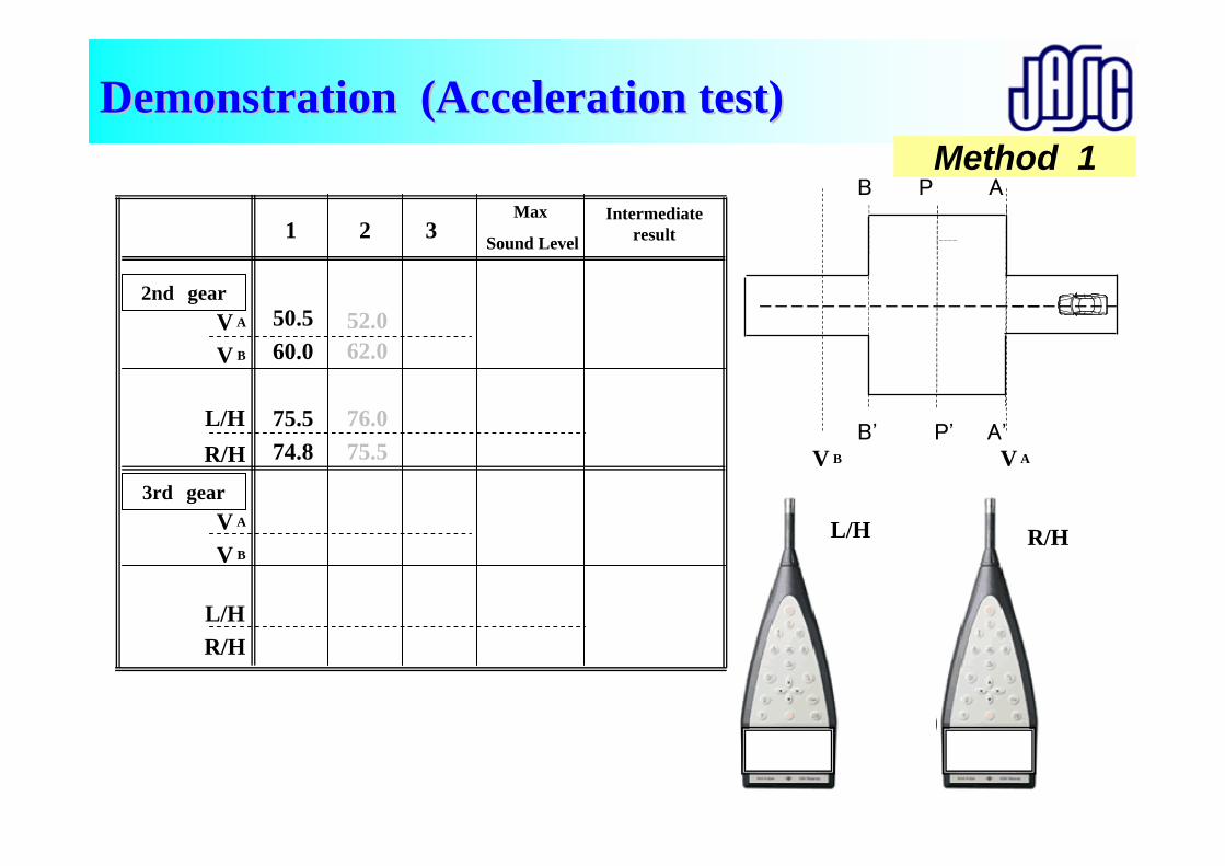
P'V AV B
P AB
L/H
B' A'
-1 -1
R/H
1 2 3Max
Sound Level
Intermediate result
2nd gearV A
V B
L/HR/H
3rd gearV A
V B
L/HR/H
50.560.0
75.574.8
52.062.0
76.075.5
76.576.0
72.572.5
76.5
72.5
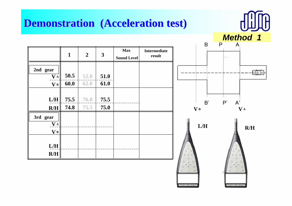
Demonstration (Acceleration test)Demonstration (Acceleration test)Method 1
P'V AV B
P AB
L/H
B' A'
-1 -1
51.061.0
76.5 76.0
R/H
1 2 3Max
Sound Level
Intermediate result
2nd gearV A
V B
L/HR/H
3rd gearV A
V B
L/HR/H
50.560.0
75.574.8
50.058.5
69.070.0
52.062.0
76.075.5
50.859.0
71.571.55
51.061.0
75.575.0
50.558.5
71.071.0
76.576.0
72.572.5
76.5
72.5
Demonstration (Acceleration test)Demonstration (Acceleration test)Method 1
P'V AV B
P AB
L/H
B' A'
-1 -1
50.058.5
70.0 71.0
R/H
1 2 3Max
Sound Level
Intermediate result
2nd gearV A
V B
L/HR/H
3rd gearV A
V B
L/HR/H
50.560.0
75.574.8
50.058.5
69.070.0
52.062.0
76.075.5
50.859.0
71.571.55
51.061.0
75.575.0
50.558.5
71.071.0
76.576.0
72.572.5
76.5
72.5
Demonstration (Acceleration test)Demonstration (Acceleration test)Method 1
P'V AV B
P AB
L/H
B' A'
-1 -1
50.859.0
72.5 72.5
R/H
1 2 3Max
Sound Level
Intermediate result
2nd gearV A
V B
L/HR/H
3rd gearV A
V B
L/HR/H
50.560.0
75.574.8
50.058.5
69.070.0
52.062.0
76.075.5
50.859.0
71.571.5
51.061.0
75.575.0
50.558.5
71.071.0
76.576.0
72.572.5
76.5
72.5
Demonstration (Acceleration test)Demonstration (Acceleration test)Method 1

P'V AV B
P AB
L/H
B' A'
-1 -1
50.558.5
72.0 72.0
R/H
1 2 3Max
Sound Level
Intermediate result
2nd gearV A
V B
L/HR/H
3rd gearV A
V B
L/HR/H
50.560.0
75.574.8
50.058.5
69.070.0
52.062.0
76.075.5
50.859.0
71.571.5
51.061.0
75.575.0
50.558.5
71.071.0
76.576.0
72.572.5
76.5
72.5
>2dB
Demonstration (Acceleration test)Demonstration (Acceleration test)Method 1
P'V AV B
P AB
L/H
B' A'
-1 -1
R/H
1 2 3Max
Sound Level
Intermediate result
2nd gearV A
V B
L/HR/H
3rd gearV A
V B
L/HR/H
50.560.0
75.574.8
50.058.5
69.070.0
52.062.0
76.075.5
50.859.0
71.571.5
51.061.0
75.575.0
50.558.5
71.071.0
76.576.0
72.572.5
76.5
72.5
>2dB
Demonstration (Acceleration test)Demonstration (Acceleration test)Method 1

P'V AV B
P AB
L/H
B' A'
-1 -1
R/H
1 2 3Max
Sound Level
Intermediate result
2nd gearV A
V B
L/HR/H
3rd gearV A
V B
L/HR/H
50.560.0
75.574.8
50.058.5
69.070.0
52.062.0
76.075.5
50.859.0
71.571.5
51.061.0
75.575.0
50.558.5
71.071.0
76.576.0
72.572.5
76.5
72.5
75.575.0
71.571.5
75.5
71.5
Demonstration (Acceleration test)Demonstration (Acceleration test)
75.5+71.52
Final Result : = 73.5
Maximum of two runs on the same side
Maximum of L/H and R/H side
Method 1
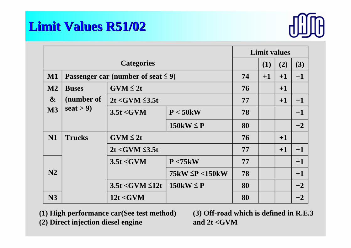
Limit Values R51/02 Limit Values R51/02
+2+2+1+1+1
+2
+1+1
+1(3)
+1+1
+1+1+1(2)
+1(1)
N3150kW ≤ P75kW ≤P <150kWP <75kW
8012t <GVM803.5t <GVM ≤12t78N2
80150kW ≤ P
P < 50kW
N1 Trucks
Buses(number of seat > 9)
Passenger car (number of seat ≤ 9)GVM ≤ 2t
773.5t <GVM772t <GVM ≤3.5t76GVM ≤ 2t
783.5t <GVM777674
Limit values
2t <GVM ≤3.5tM2&
M3
M1
Categories
(1) High performance car(See test method)(2) Direct injection diesel engine
(3) Off-road which is defined in R.E.3 and 2t <GVM
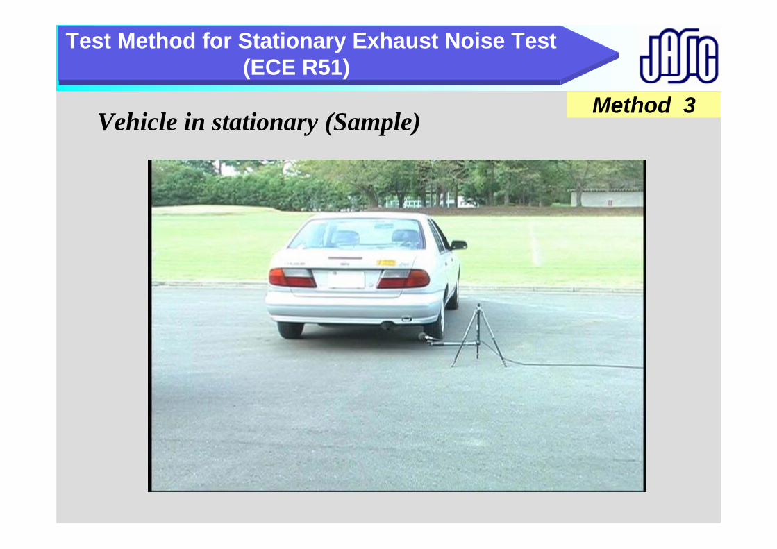
Test Method for Stationary Exhaust Noise Test (ECE R51)
Method 3Vehicle in stationary (Sample)

Purpose of stationary noise Purpose of stationary noise Aim of stationary noise test is mentioned in UN/ECE /WP29 RE3.
1.5.1.2. Methods of measuring the sound level.
….. The test on the vehicle when stationary may usefully be taken as a reference value by technical services wishing to use this method to check vehicles in service.
……..1.5.2.2. In view of the tolerances of measuring instruments, the disturbances that may occur at the time of
measurement and the scatter of measurements for vehicles of the same type, it will TRANS/WP.29/78/Rev.1 be necessary to allow for a margin of 5 dB(A) in comparison with the corresponding value recorded at the time of the type approval.
in use noise enforcement in national regulation level. It may be used with at least 5dB for margin.
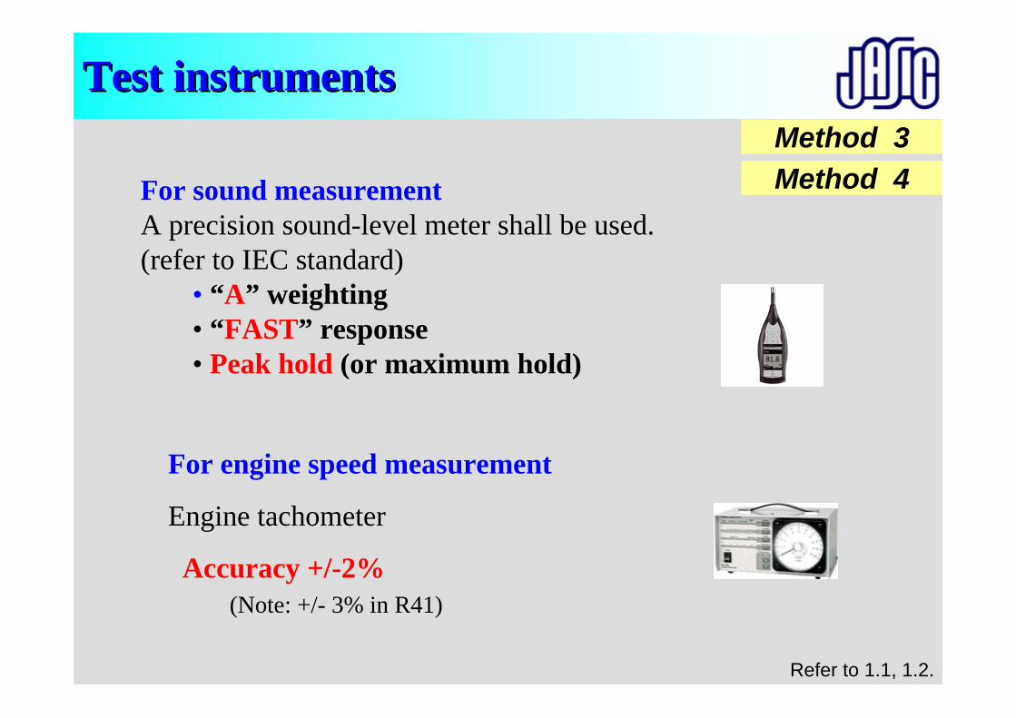
Test instrumentsTest instruments
For sound measurementA precision sound-level meter shall be used. (refer to IEC standard)
• “A” weighting• “FAST” response• Peak hold (or maximum hold)
For engine speed measurement
Engine tachometer
Accuracy +/-2%(Note: +/- 3% in R41)
Method 3Method 4
Refer to 1.1, 1.2.
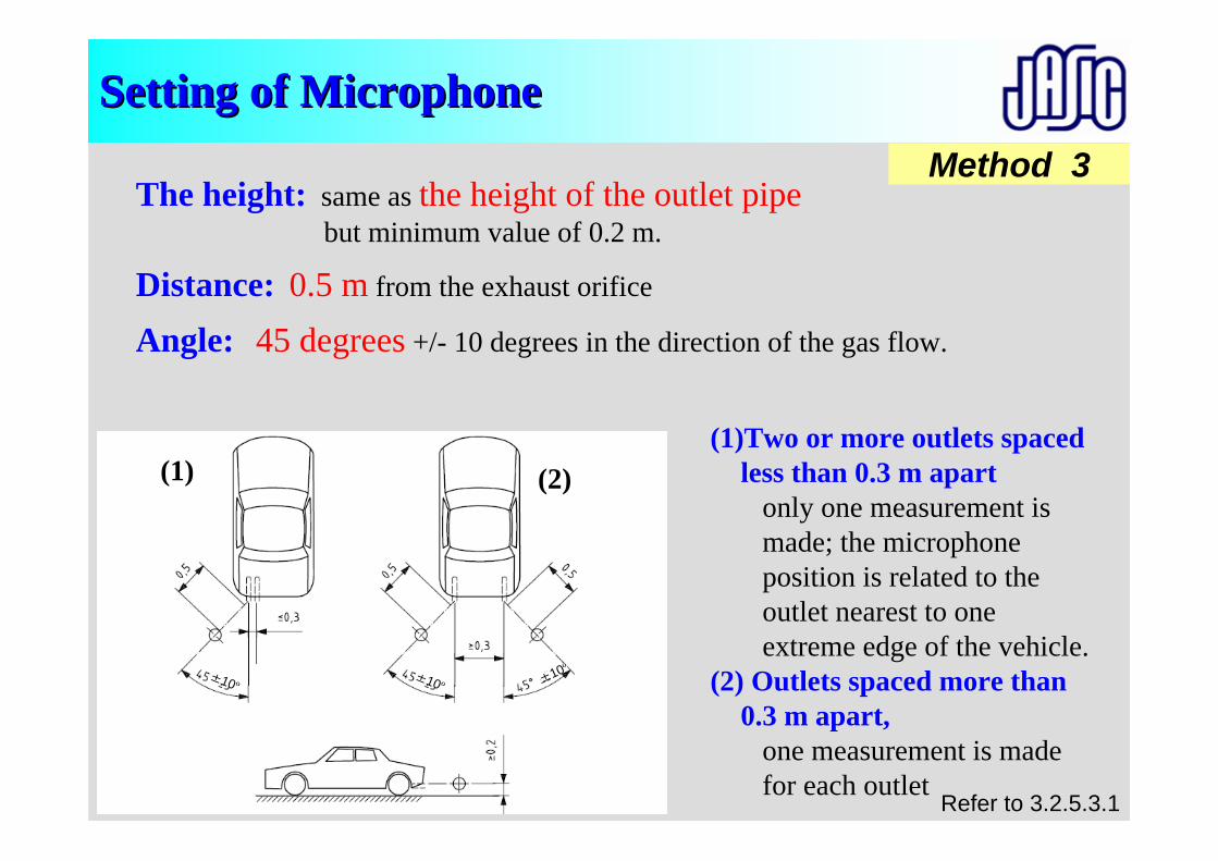
±10º
Method 3
Setting of Microphone Setting of Microphone
(1)Two or more outlets spaced less than 0.3 m apart
only one measurement is made; the microphone position is related to the outlet nearest to one extreme edge of the vehicle.
(2) Outlets spaced more than 0.3 m apart,
one measurement is made for each outlet
The height: same as the height of the outlet pipebut minimum value of 0.2 m.
Distance: 0.5 m from the exhaust orifice
Angle: 45 degrees +/- 10 degrees in the direction of the gas flow.
(1) (2)
Refer to 3.2.5.3.1
±10º±10º
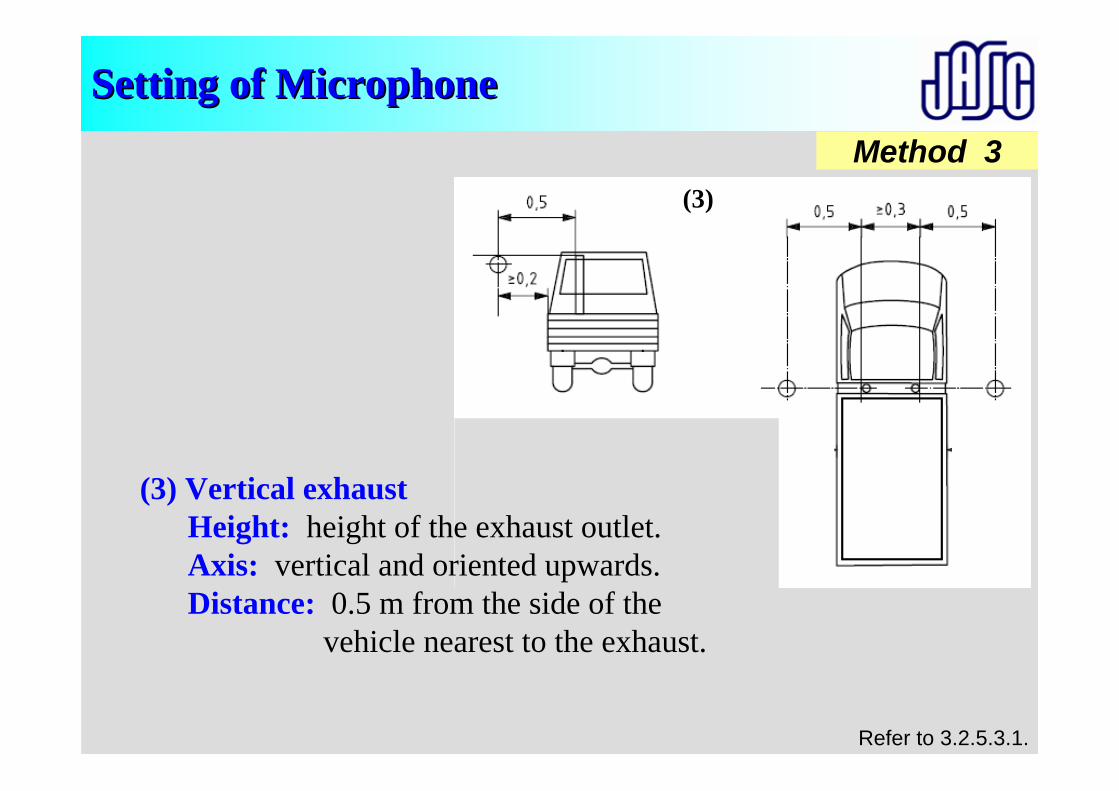
Method 3
Setting of MicrophoneSetting of Microphone
(3)
(3)
(3) Vertical exhaustHeight: height of the exhaust outlet. Axis: vertical and oriented upwards. Distance: 0.5 m from the side of the
vehicle nearest to the exhaust.
Refer to 3.2.5.3.1.
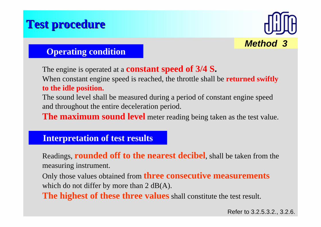
Test procedure Test procedure Method 3
Readings, rounded off to the nearest decibel, shall be taken from the measuring instrument.Only those values obtained from three consecutive measurementswhich do not differ by more than 2 dB(A).The highest of these three values shall constitute the test result.
The engine is operated at a constant speed of 3/4 S.When constant engine speed is reached, the throttle shall be returned swiftly to the idle position.The sound level shall be measured during a period of constant engine speed and throughout the entire deceleration period.The maximum sound level meter reading being taken as the test value.
Refer to 3.2.5.3.2., 3.2.6.
Operating condition
Interpretation of test results
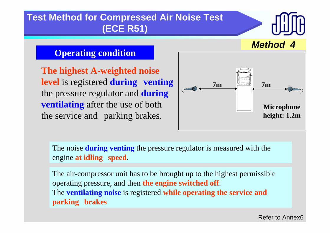
Method 4
Compressed air noiseTest Method for Compressed Air Noise Test (ECE R51)
Refer to Annex6
The highest A-weighted noise level is registered during ventingthe pressure regulator and during ventilating after the use of both the service and parking brakes.
Operating condition
The noise during venting the pressure regulator is measured with the engine at idling speed.
The air-compressor unit has to be brought up to the highest permissible operating pressure, and then the engine switched off.The ventilating noise is registered while operating the service and parking brakes
Microphone height: 1.2m
7m 7m
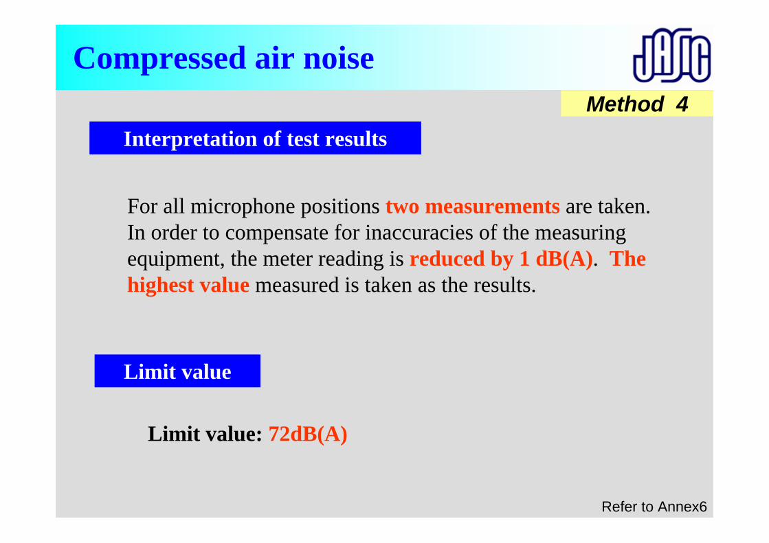
Limit value: 72dB(A)
Method 4
Compressed air noise
For all microphone positions two measurements are taken. In order to compensate for inaccuracies of the measuring equipment, the meter reading is reduced by 1 dB(A). The highest value measured is taken as the results.
Interpretation of test results
Limit value
Refer to Annex6

Important Important pointspoints
The important points for correct noise data
1. Carrying out calibration of the sound level meter in every test.
2. Taking care of low and stable ambient noise
3. Reducing the factors for variation of noise level;
• Approach speed (+/- 1km/h)
• Timing (place) of wide-open -throttle (as close to AA’ line as possible)
• Stability of opening the throttle during measurement to in stationary test
4. Selection and maintenance of road surface for noise test
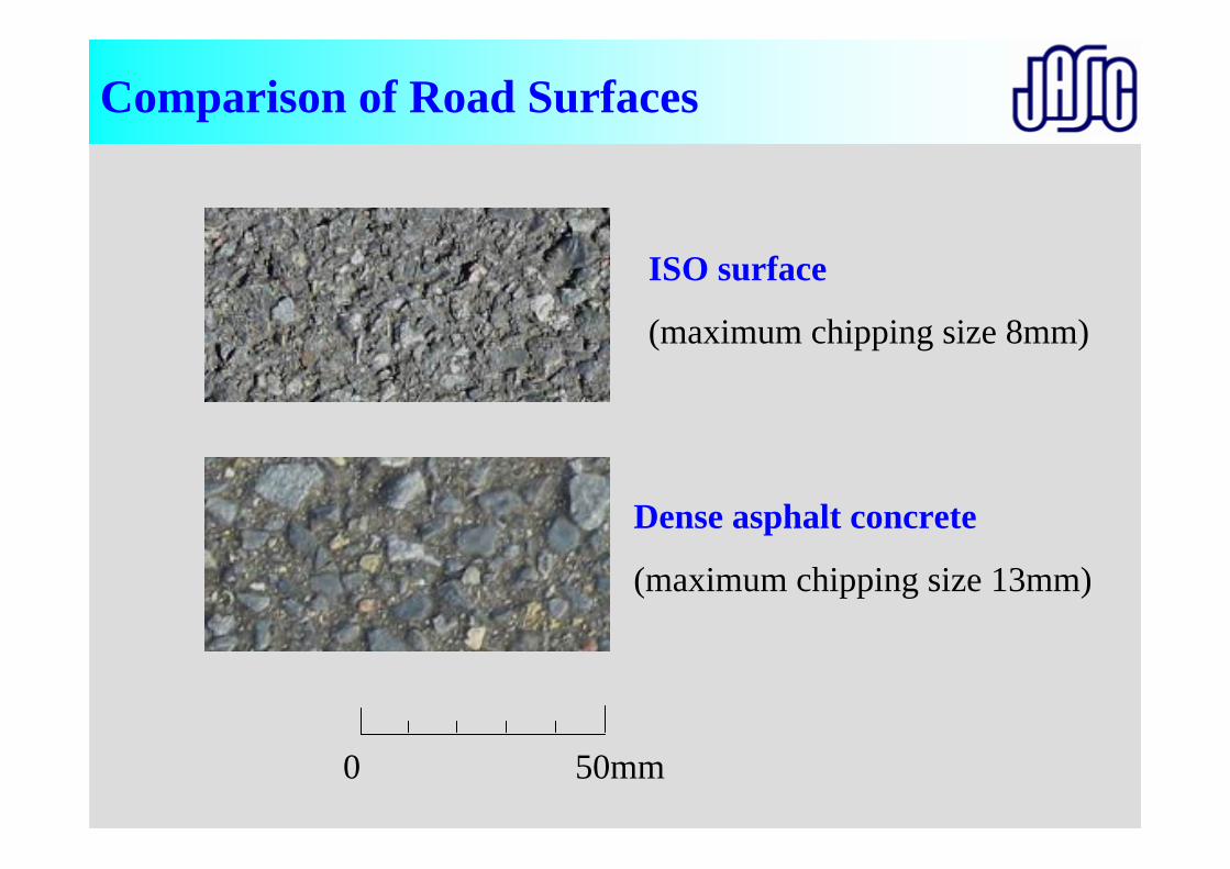
0 50mm
ISO surface
(maximum chipping size 8mm)
Dense asphalt concrete
(maximum chipping size 13mm)
Comparison of Road Surfaces
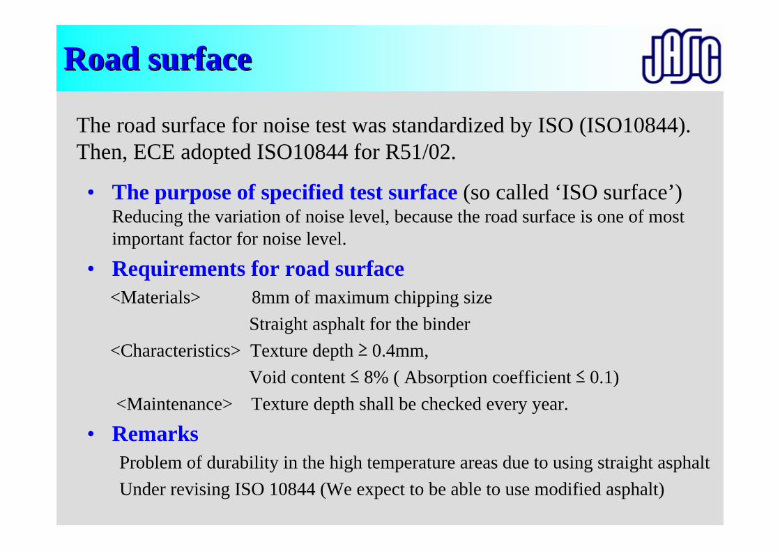
Road surfaceRoad surface
• The purpose of specified test surface (so called ‘ISO surface’) Reducing the variation of noise level, because the road surface is one of most important factor for noise level.
• Requirements for road surface<Materials> 8mm of maximum chipping size
Straight asphalt for the binder<Characteristics> Texture depth ≥ 0.4mm,
Void content ≤ 8% ( Absorption coefficient ≤ 0.1)<Maintenance> Texture depth shall be checked every year.
• Remarks Problem of durability in the high temperature areas due to using straight asphaltUnder revising ISO 10844 (We expect to be able to use modified asphalt)
The road surface for noise test was standardized by ISO (ISO10844). Then, ECE adopted ISO10844 for R51/02.

Thank you very muchThank you very muchfor your attentionfor your attention

General informationR43
Masaru MorikawaJASIC
Asia Expert Meeting
What is R43• R43 is a
“UNIFORM PROVISIONS CONCERNING THE APPROVAL OF SAFETY GLAZING MATERIALS AND THEIR INSTALLATION ON VEHICLES”
Original version was adopted in 1981.
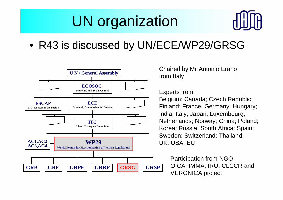
UN organization• R43 is discussed by UN/ECE/WP29/GRSG
ECEEconomic Commission for Europe
WP29World Forum for Harmonization of Vehicle Regulations
AC1,AC2AC3,AC4
U N / General Assembly
GRPE GRSPGRSGGRRFGRE
ITCInland Transport Committee
ECOSOCEconomic and Social Council
GRB
Chaired by Mr.Antonio Erario from Italy
Experts from;Belgium; Canada; Czech Republic; Finland; France; Germany; Hungary; India; Italy; Japan; Luxembourg; Netherlands; Norway; China; Poland; Korea; Russia; South Africa; Spain; Sweden; Switzerland; Thailand; UK; USA; EU
ESCAPE. C. for Asia & the Pacific
Participation from NGO OICA; IMMA; IRU, CLCCR andVERONICA project
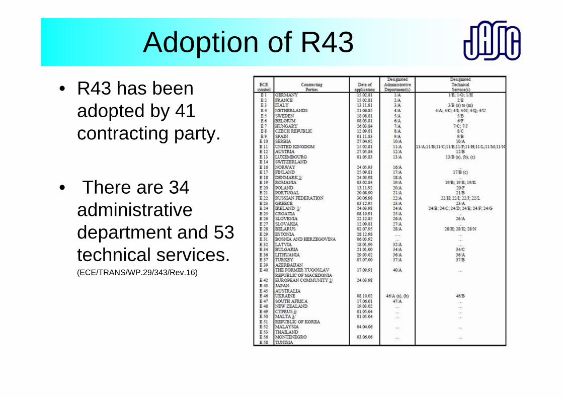
• R43 has been adopted by 41 contracting party.
• There are 34 administrative department and 53 technical services. (ECE/TRANS/WP.29/343/Rev.16)
Adoption of R43
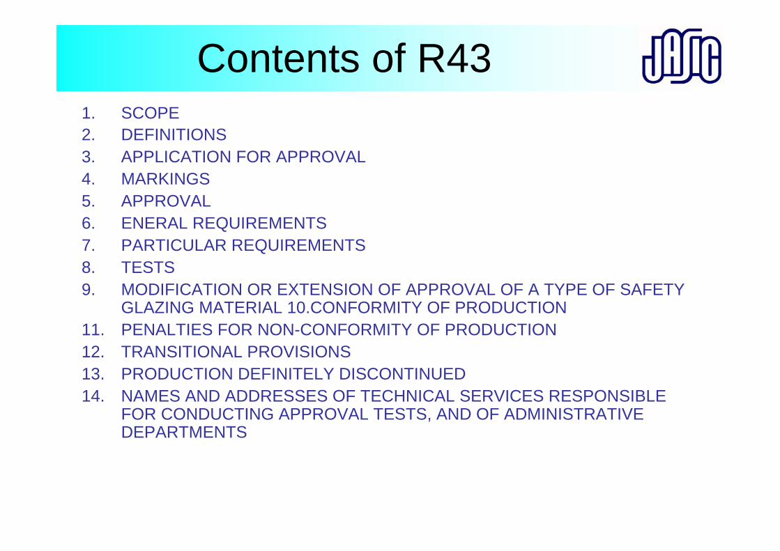
Contents of R431. SCOPE 2. DEFINITIONS3. APPLICATION FOR APPROVAL 4. MARKINGS 5. APPROVAL 6. ENERAL REQUIREMENTS 7. PARTICULAR REQUIREMENTS 8. TESTS 9. MODIFICATION OR EXTENSION OF APPROVAL OF A TYPE OF SAFETY
GLAZING MATERIAL 10.CONFORMITY OF PRODUCTION 11. PENALTIES FOR NON-CONFORMITY OF PRODUCTION 12. TRANSITIONAL PROVISIONS 13. PRODUCTION DEFINITELY DISCONTINUED 14. NAMES AND ADDRESSES OF TECHNICAL SERVICES RESPONSIBLE
FOR CONDUCTING APPROVAL TESTS, AND OF ADMINISTRATIVE DEPARTMENTS
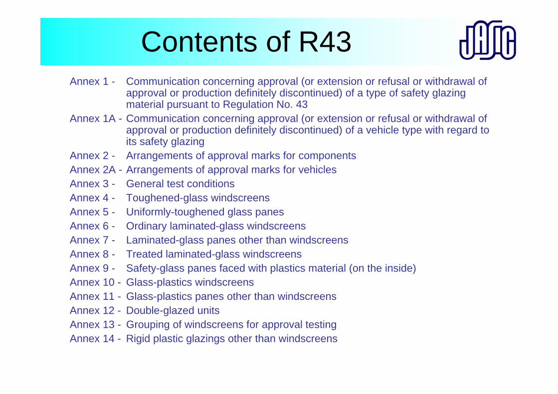
Contents of R43Annex 1 - Communication concerning approval (or extension or refusal or withdrawal of
approval or production definitely discontinued) of a type of safety glazing material pursuant to Regulation No. 43
Annex 1A - Communication concerning approval (or extension or refusal or withdrawal of approval or production definitely discontinued) of a vehicle type with regard to its safety glazing
Annex 2 - Arrangements of approval marks for componentsAnnex 2A - Arrangements of approval marks for vehiclesAnnex 3 - General test conditionsAnnex 4 - Toughened-glass windscreensAnnex 5 - Uniformly-toughened glass panesAnnex 6 - Ordinary laminated-glass windscreensAnnex 7 - Laminated-glass panes other than windscreensAnnex 8 - Treated laminated-glass windscreens Annex 9 - Safety-glass panes faced with plastics material (on the inside)Annex 10 - Glass-plastics windscreens Annex 11 - Glass-plastics panes other than windscreensAnnex 12 - Double-glazed unitsAnnex 13 - Grouping of windscreens for approval testingAnnex 14 - Rigid plastic glazings other than windscreens
ScopeThis Regulation applies to:(a) safety glazing materials intended for
installation as windscreens or other panes, or as partitioning, on vehicles of category L, M, N, O, and T
(b) vehicles of category M, N and O with regard to the installation of these materials;
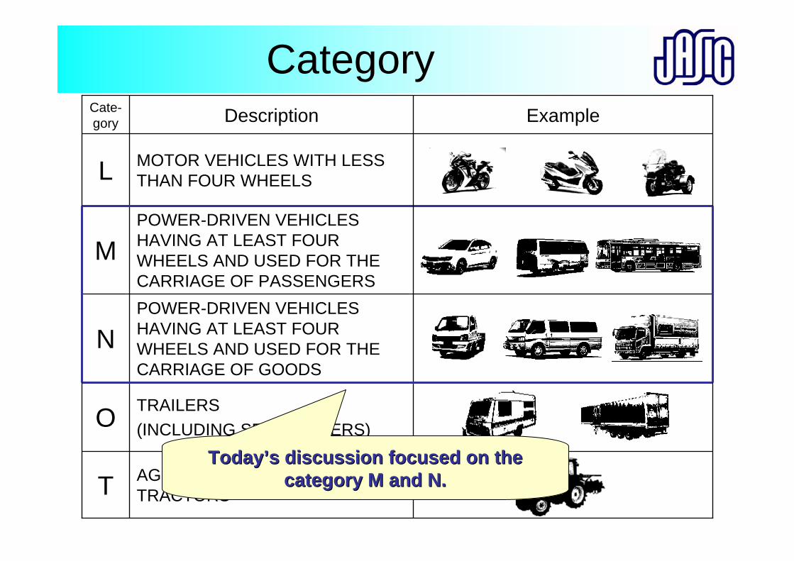
Category
TRAILERS(INCLUDING SEMITRAILERS)O
POWER-DRIVEN VEHICLES HAVING AT LEAST FOUR WHEELS AND USED FOR THE CARRIAGE OF GOODS
N
Example
MOTOR VEHICLES WITH LESS THAN FOUR WHEELSL
AGRICULTURAL AND FORESTRY TRACTORST
POWER-DRIVEN VEHICLES HAVING AT LEAST FOUR WHEELS AND USED FOR THE CARRIAGE OF PASSENGERS
M
DescriptionCate-gory
TodayToday’’s discussion focused on the s discussion focused on the category M and N. category M and N.
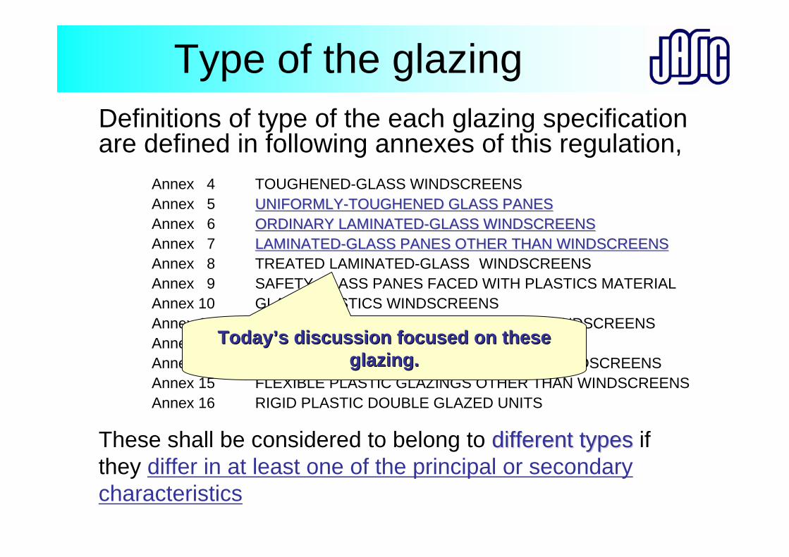
Type of the glazingDefinitions of type of the each glazing specification are defined in following annexes of this regulation,
These shall be considered to belong to different typesdifferent types if they differ in at least one of the principal or secondary characteristics
Annex 4 TOUGHENED-GLASS WINDSCREENSAnnex 5 UNIFORMLYUNIFORMLY--TOUGHENED GLASS PANESTOUGHENED GLASS PANESAnnex 6 ORDINARY LAMINATEDORDINARY LAMINATED--GLASS WINDSCREENSGLASS WINDSCREENSAnnex 7 LAMINATEDLAMINATED--GLASS PANES OTHER THAN WINDSCREENSGLASS PANES OTHER THAN WINDSCREENSAnnex 8 TREATED LAMINATED-GLASS WINDSCREENSAnnex 9 SAFETY-GLASS PANES FACED WITH PLASTICS MATERIALAnnex 10 GLASS-PLASTICS WINDSCREENSAnnex 11 GLASS-PLASTICS PANES OTHER THAN WINDSCREENSAnnex 12 DOUBLE-GLAZED UNITSAnnex 14 RIGID PLASTIC GLAZINGS OTHER THAN WINDSCREENSAnnex 15 FLEXIBLE PLASTIC GLAZINGS OTHER THAN WINDSCREENSAnnex 16 RIGID PLASTIC DOUBLE GLAZED UNITS
TodayToday’’s discussion focused on these s discussion focused on these glazing.glazing.
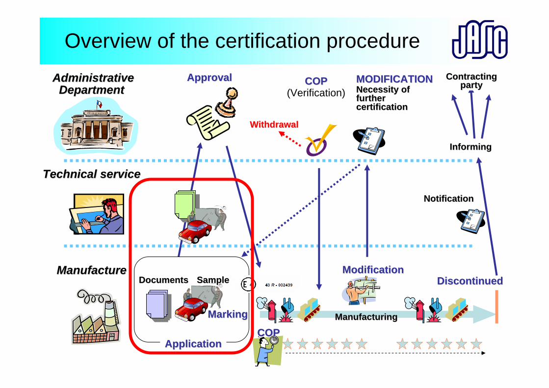
Overview of the certification procedureAdministrativeAdministrative
Department Department
Technical service Technical service
Manufacture Manufacture
ApplicationApplication
ApprovalApproval
COPCOP
COPCOP(Verification)
ModificationModification
ManufacturingManufacturing
MODIFICATIONMODIFICATIONNecessity ofNecessity offurtherfurthercertificationcertification
MarkingMarking
DiscontinuedDiscontinuedSampleSampleDocumentsDocuments
NotificationNotification
InformingInforming
ContractingContractingpartyparty
WithdrawalWithdrawal
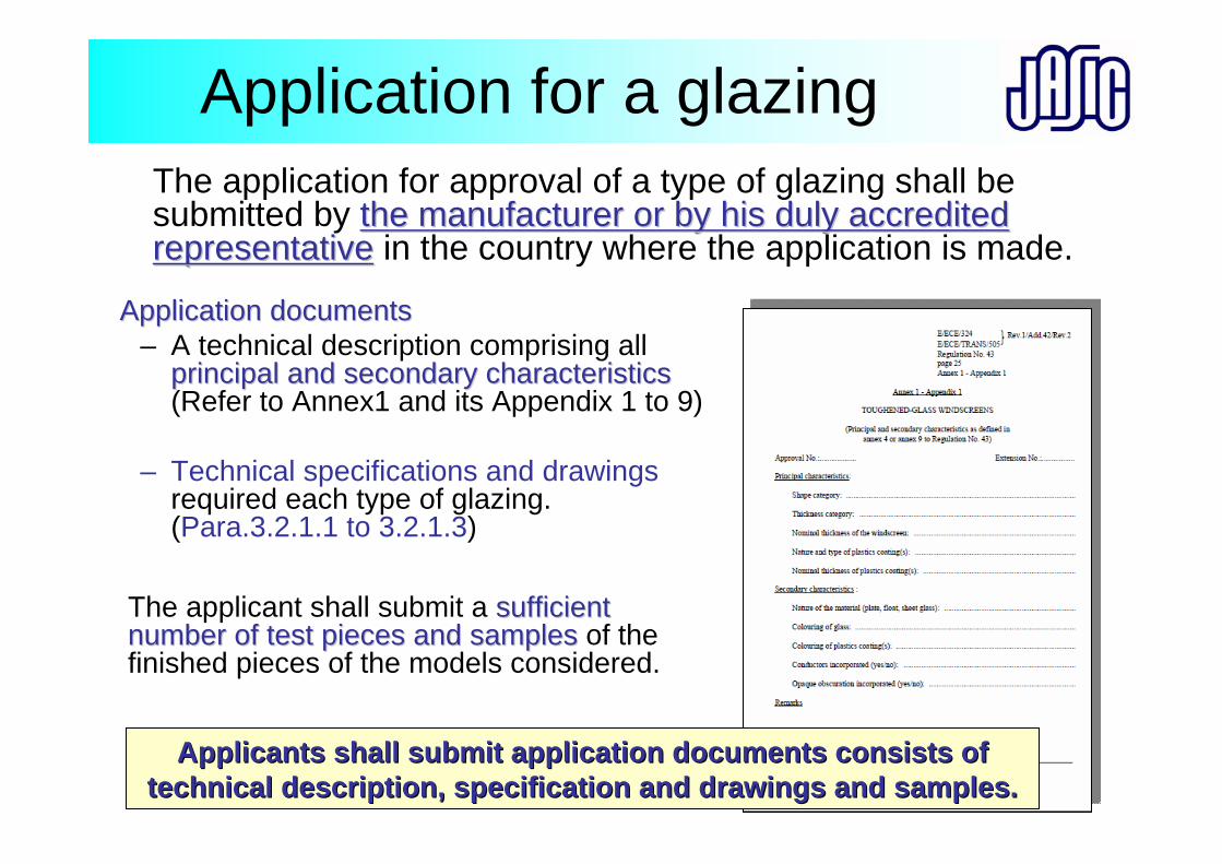
Application for a glazingThe application for approval of a type of glazing shall be submitted by the manufacturer or by his duly accredited the manufacturer or by his duly accredited representativerepresentative in the country where the application is made.
AApplication documentspplication documents– A technical description comprising all
principal and secondary characteristicsprincipal and secondary characteristics(Refer to Annex1 and its Appendix 1 to 9)
– Technical specifications and drawingsrequired each type of glazing. (Para.3.2.1.1 to 3.2.1.3)
The applicant shall submit a sufficient sufficient number of test pieces and samplesnumber of test pieces and samples of the finished pieces of the models considered.
Applicants shall submit application documents consists of Applicants shall submit application documents consists of technical description, specification and drawings and samples.technical description, specification and drawings and samples.
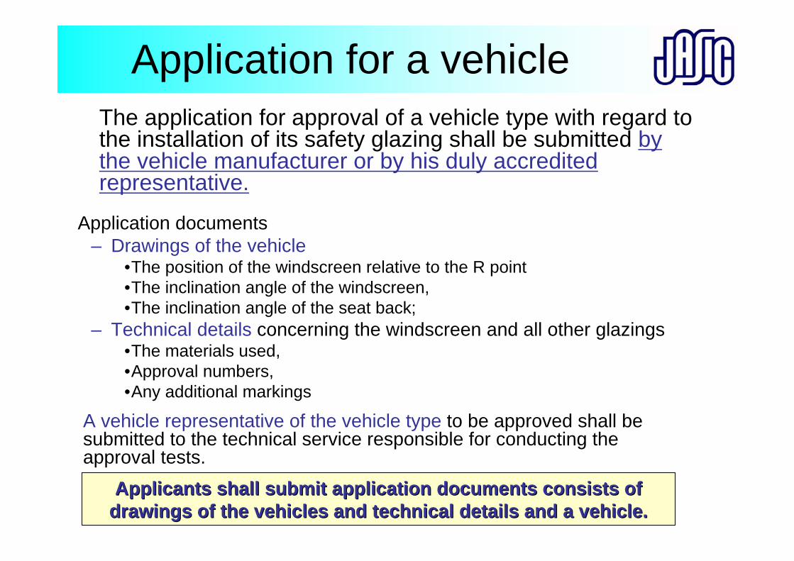
Application for a vehicleThe application for approval of a vehicle type with regard to the installation of its safety glazing shall be submitted by the vehicle manufacturer or by his duly accredited representative.
Application documents– Drawings of the vehicle
•The position of the windscreen relative to the R point•The inclination angle of the windscreen,•The inclination angle of the seat back;
– Technical details concerning the windscreen and all other glazings•The materials used,•Approval numbers,•Any additional markings
A vehicle representative of the vehicle type to be approved shall be submitted to the technical service responsible for conducting the approval tests.
Applicants shall submit application documents consists of Applicants shall submit application documents consists of drawings of the vehicles and technical details and a vehicle.drawings of the vehicles and technical details and a vehicle.
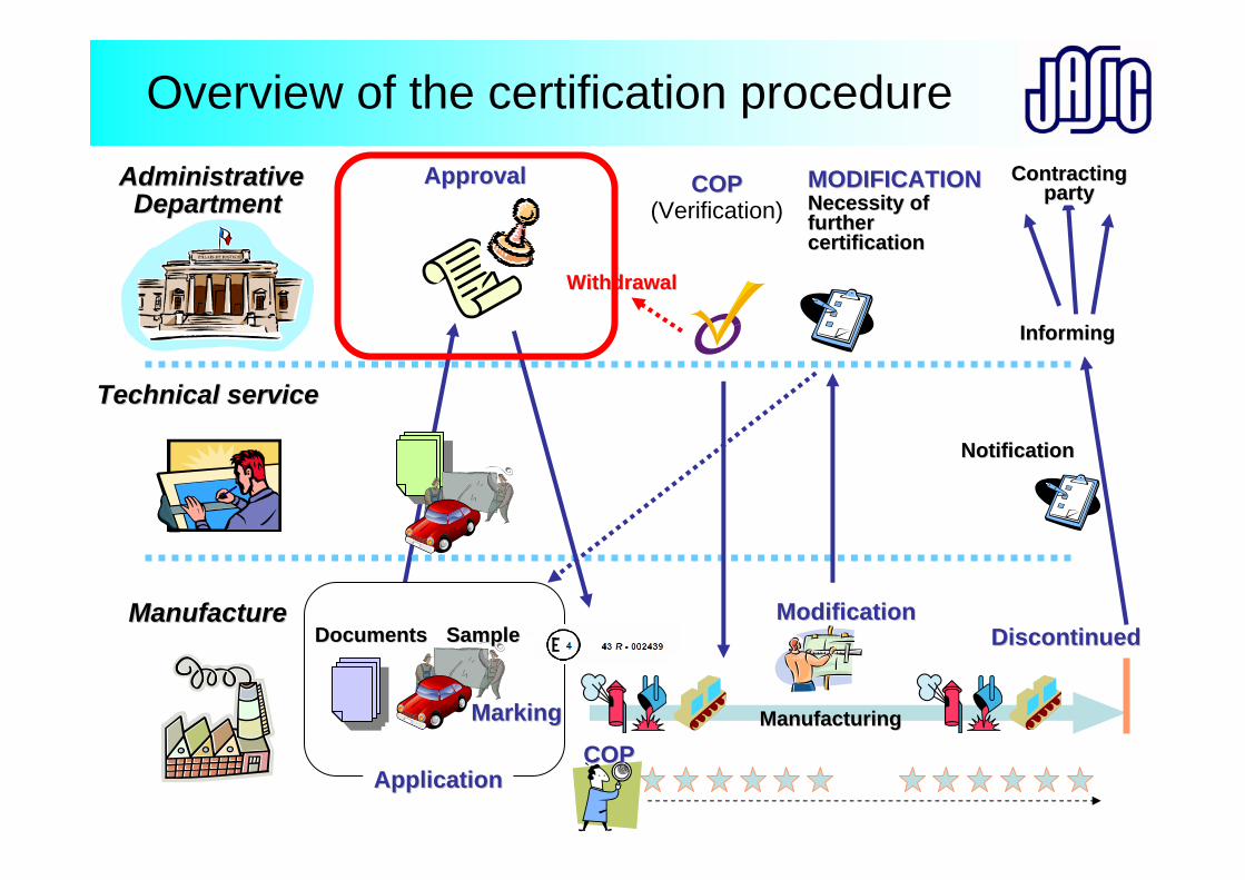
Overview of the certification procedureAdministrativeAdministrative
Department Department
Technical service Technical service
Manufacture Manufacture
ApplicationApplication
ApprovalApproval
COPCOP
COPCOP(Verification)
ModificationModification
ManufacturingManufacturing
MODIFICATIONMODIFICATIONNecessity ofNecessity offurtherfurthercertificationcertification
MarkingMarking
DiscontinuedDiscontinuedSampleSampleDocumentsDocuments
NotificationNotification
InformingInforming
ContractingContractingpartyparty
WithdrawalWithdrawal
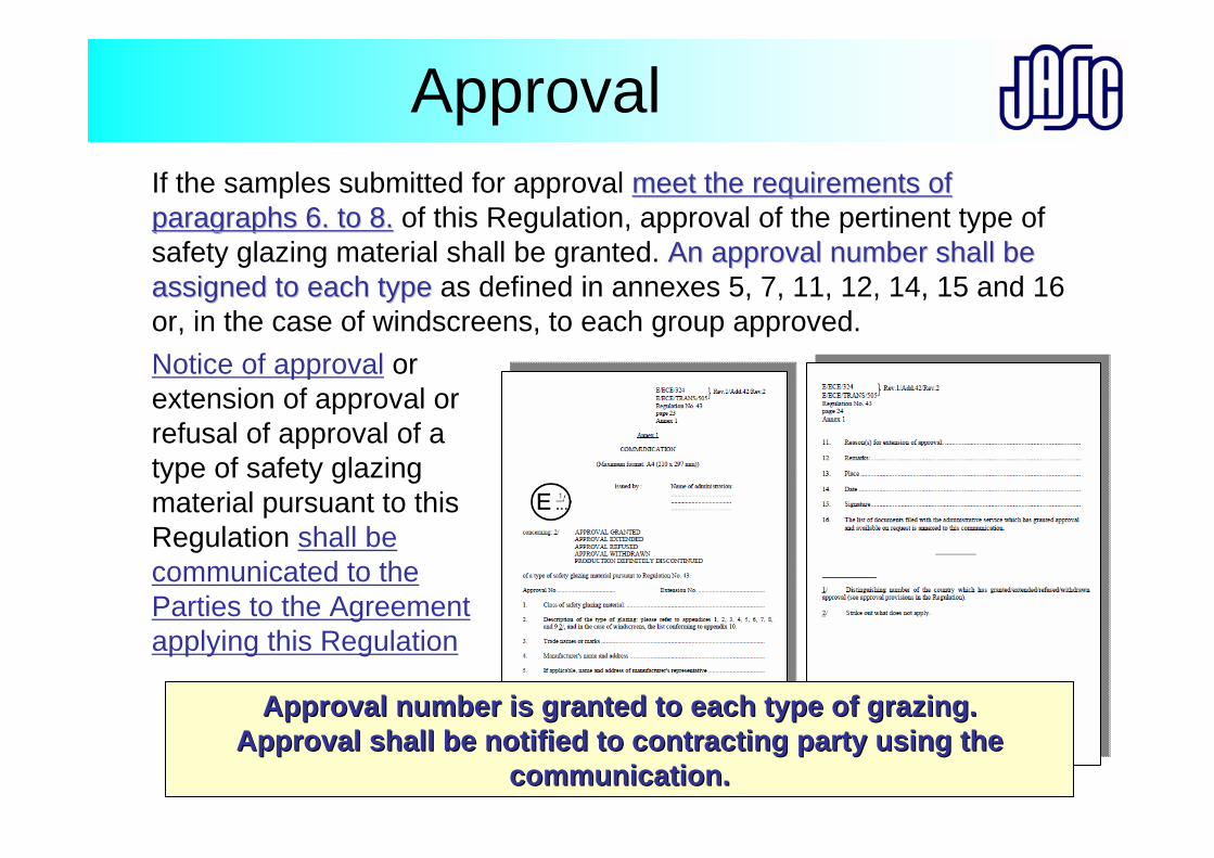
Approval If the samples submitted for approval meet the requirements ofmeet the requirements ofparagraphs 6. to 8.paragraphs 6. to 8. of this Regulation, approval of the pertinent type of safety glazing material shall be granted. An approval number shall be An approval number shall be assigned to each typeassigned to each type as defined in annexes 5, 7, 11, 12, 14, 15 and 16 or, in the case of windscreens, to each group approved. Notice of approval or extension of approval or refusal of approval of a type of safety glazing material pursuant to this Regulation shall be communicated to the Parties to the Agreement applying this Regulation
Approval number is granted to each type of grazing.Approval number is granted to each type of grazing.Approval shall be notified to contracting party using the Approval shall be notified to contracting party using the
communication. communication.
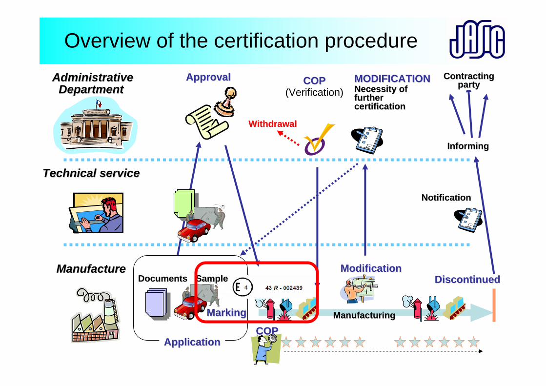
Overview of the certification procedureAdministrativeAdministrative
Department Department
Technical service Technical service
Manufacture Manufacture
ApplicationApplication
ApprovalApproval
COPCOP
COPCOP(Verification)
ModificationModification
ManufacturingManufacturing
MODIFICATIONMODIFICATIONNecessity ofNecessity offurtherfurthercertificationcertification
MarkingMarking
DiscontinuedDiscontinuedSampleSampleDocumentsDocuments
NotificationNotification
InformingInforming
ContractingContractingpartyparty
WithdrawalWithdrawal
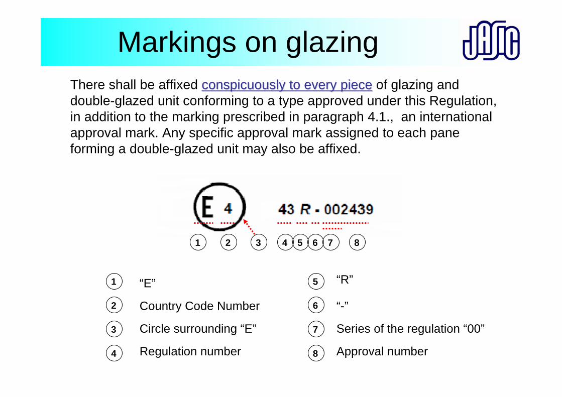
Markings on glazingThere shall be affixed conspicuously to every piececonspicuously to every piece of glazing and double-glazed unit conforming to a type approved under this Regulation,in addition to the marking prescribed in paragraph 4.1., an international approval mark. Any specific approval mark assigned to each pane forming a double-glazed unit may also be affixed.
1 2 3 4 5 6 7 8
1
2
3
4
5
6
7
8
“E”
Country Code Number
Circle surrounding “E”
Regulation number
“R”
Series of the regulation “00”
“-”
Approval number
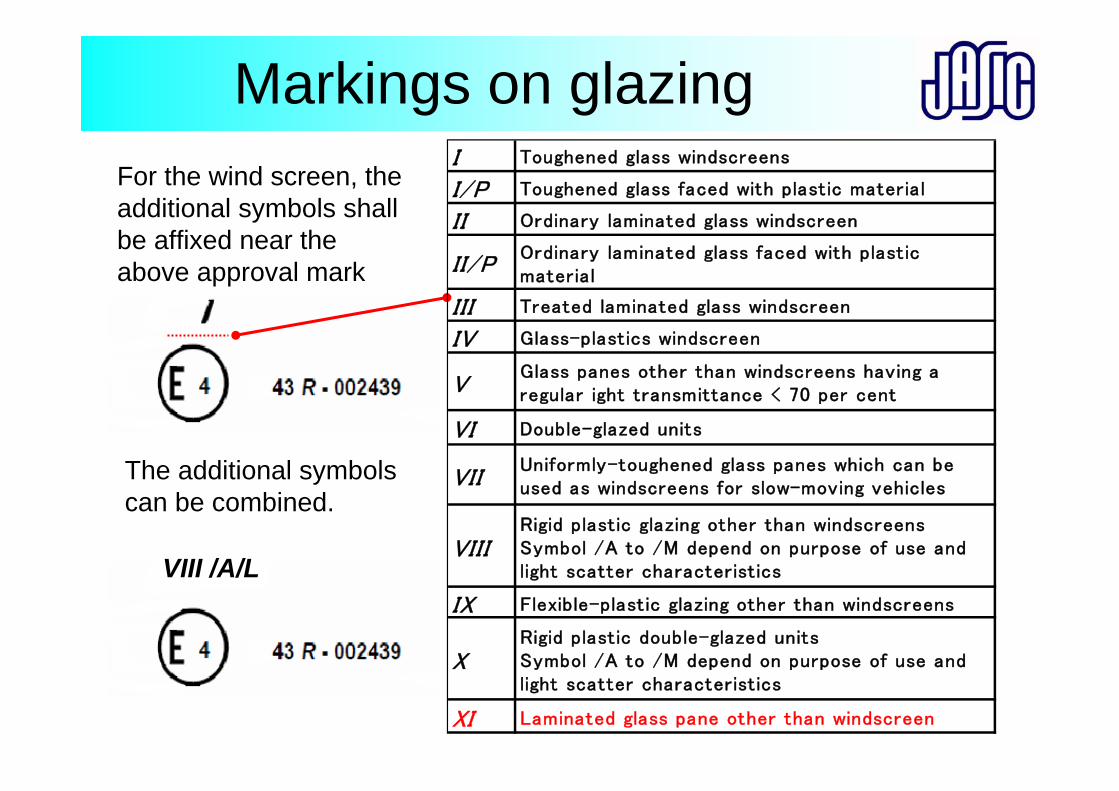
Markings on glazingFor the wind screen, the additional symbols shall be affixed near the above approval mark
The additional symbols can be combined.
VIII /A/L
I Toughened glass windscreens
I/P Toughened glass faced with plastic material
II Ordinary laminated glass windscreen
II/POrdinary laminated glass faced with plasticmaterial
III Treated laminated glass windscreen
IV Glass-plastics windscreen
VGlass panes other than windscreens having aregular ight transmittance < 70 per cent
VI Double-glazed units
VIIUniformly-toughened glass panes which can beused as windscreens for slow-moving vehicles
VIIIRigid plastic glazing other than windscreensSymbol /A to /M depend on purpose of use andlight scatter characteristics
IX Flexible-plastic glazing other than windscreens
XRigid plastic double-glazed unitsSymbol /A to /M depend on purpose of use andlight scatter characteristics
XI Laminated glass pane other than windscreen
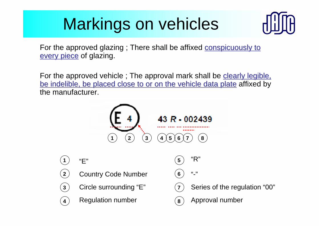
Markings on vehiclesFor the approved glazing ; There shall be affixed conspicuously to conspicuously to every pieceevery piece of glazing.
For the approved vehicle ; The approval mark shall be clearly legible, clearly legible, be indelible, be placed close to or on the vehicle data platebe indelible, be placed close to or on the vehicle data plate affixed by the manufacturer.
1 2 3 4 5 6 7 8
1
2
3
4
5
6
7
8
“E”
Country Code Number
Circle surrounding “E”
Regulation number
“R”
Series of the regulation “00”
“-”
Approval number
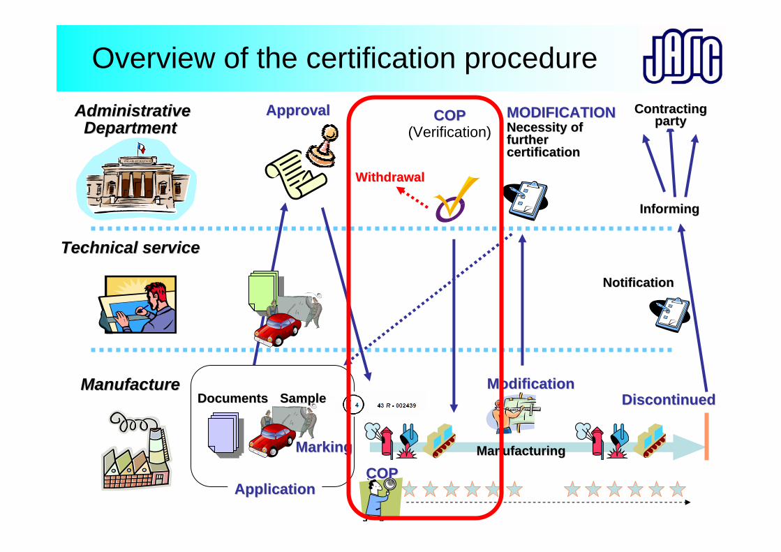
Overview of the certification procedureAdministrativeAdministrative
Department Department
Technical service Technical service
Manufacture Manufacture
ApplicationApplication
ApprovalApproval
COPCOP
COPCOP(Verification)
ModificationModification
ManufacturingManufacturing
MODIFICATIONMODIFICATIONNecessity ofNecessity offurtherfurthercertificationcertification
MarkingMarking
DiscontinuedDiscontinuedSampleSampleDocumentsDocuments
NotificationNotification
InformingInforming
ContractingContractingpartyparty
WithdrawalWithdrawal
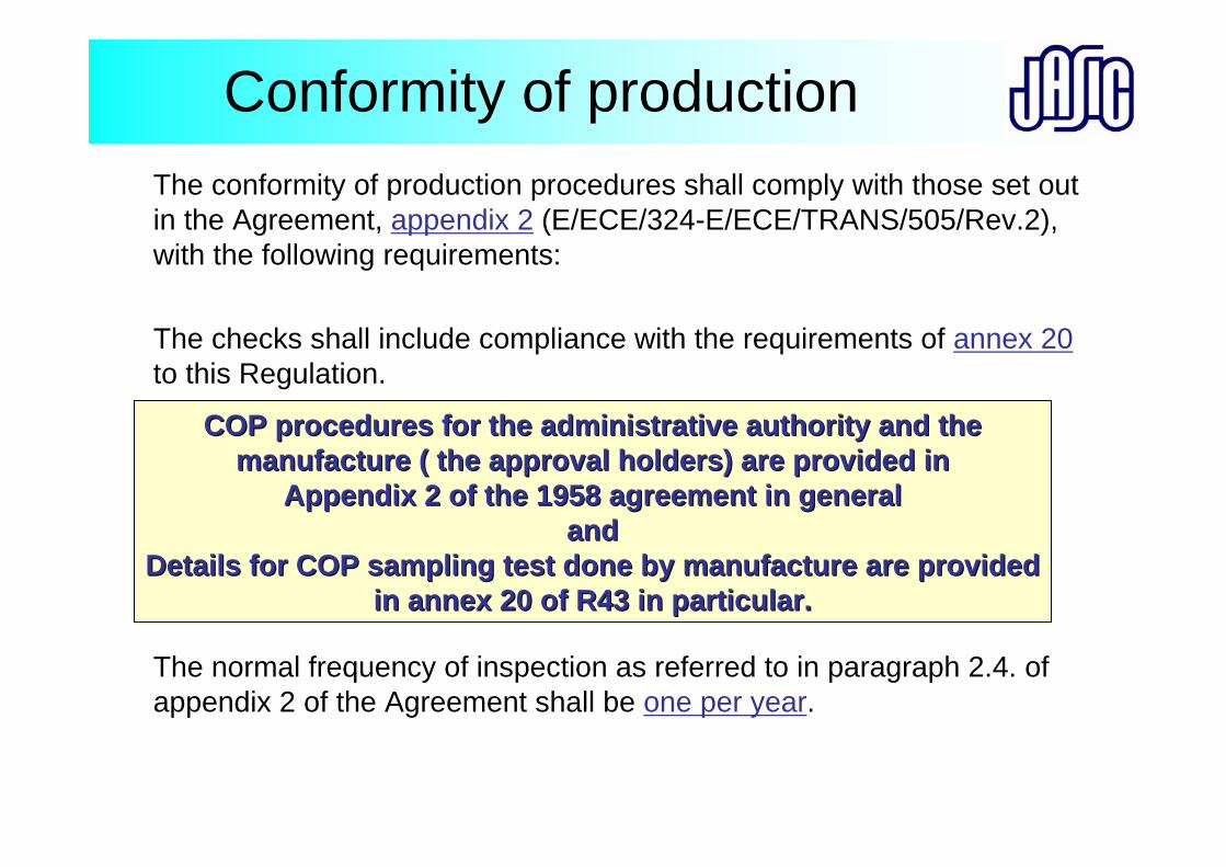
Conformity of productionThe conformity of production procedures shall comply with those set out in the Agreement, appendix 2 (E/ECE/324-E/ECE/TRANS/505/Rev.2), with the following requirements:
The checks shall include compliance with the requirements of annex 20to this Regulation.
The normal frequency of inspection as referred to in paragraph 2.4. of appendix 2 of the Agreement shall be one per year.
COP procedures for the administrative authority and the COP procedures for the administrative authority and the manufacture ( the approval holders) are provided inmanufacture ( the approval holders) are provided in
Appendix 2 of the 1958 agreement in generalAppendix 2 of the 1958 agreement in generalandand
Details for COP sampling test done by manufacture are provided Details for COP sampling test done by manufacture are provided in annex 20 of R43 in particular.in annex 20 of R43 in particular.
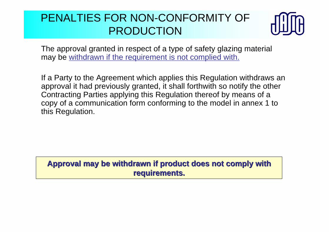
PENALTIES FOR NON-CONFORMITY OF PRODUCTION
The approval granted in respect of a type of safety glazing material may be withdrawn if the requirement is not complied with.
If a Party to the Agreement which applies this Regulation withdraws an approval it had previously granted, it shall forthwith so notify the other Contracting Parties applying this Regulation thereof by means of a copy of a communication form conforming to the model in annex 1 to this Regulation.
Approval may be withdrawn if product does not comply with Approval may be withdrawn if product does not comply with requirements.requirements.
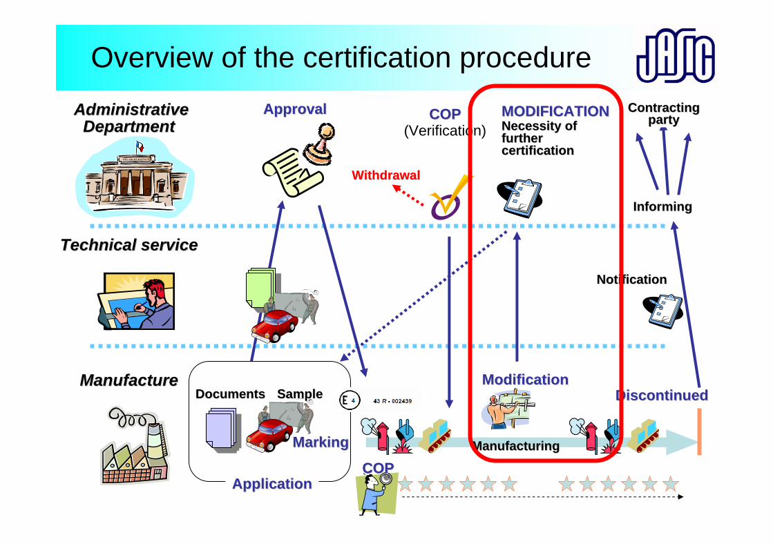
Overview of the certification procedureAdministrativeAdministrative
Department Department
Technical service Technical service
Manufacture Manufacture
ApplicationApplication
ApprovalApproval
COPCOP
COPCOP(Verification)
ModificationModification
ManufacturingManufacturing
MODIFICATIONMODIFICATIONNecessity ofNecessity offurtherfurthercertificationcertification
MarkingMarking
DiscontinuedDiscontinuedSampleSampleDocumentsDocuments
NotificationNotification
InformingInforming
ContractingContractingpartyparty
WithdrawalWithdrawal
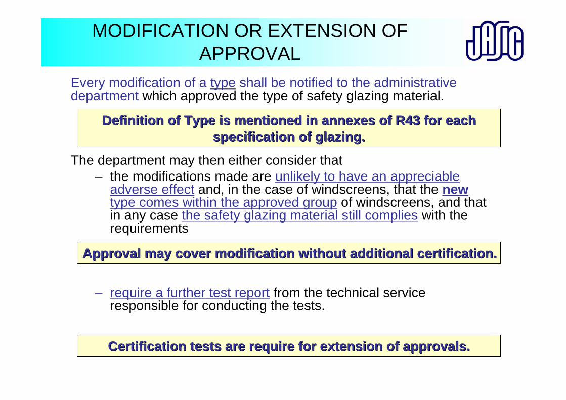
MODIFICATION OR EXTENSION OF APPROVAL
Every modification of a type shall be notified to the administrative department which approved the type of safety glazing material.
The department may then either consider that – the modifications made are unlikely to have an appreciable
adverse effect and, in the case of windscreens, that the new type comes within the approved group of windscreens, and that in any case the safety glazing material still complies with the requirements
– require a further test report from the technical service responsible for conducting the tests.
Definition of Type is mentioned in annexes of R43 for each Definition of Type is mentioned in annexes of R43 for each specification of glazing.specification of glazing.
Certification tests are require for extension of approvals.Certification tests are require for extension of approvals.
Approval may cover modification without additional certificationApproval may cover modification without additional certification..
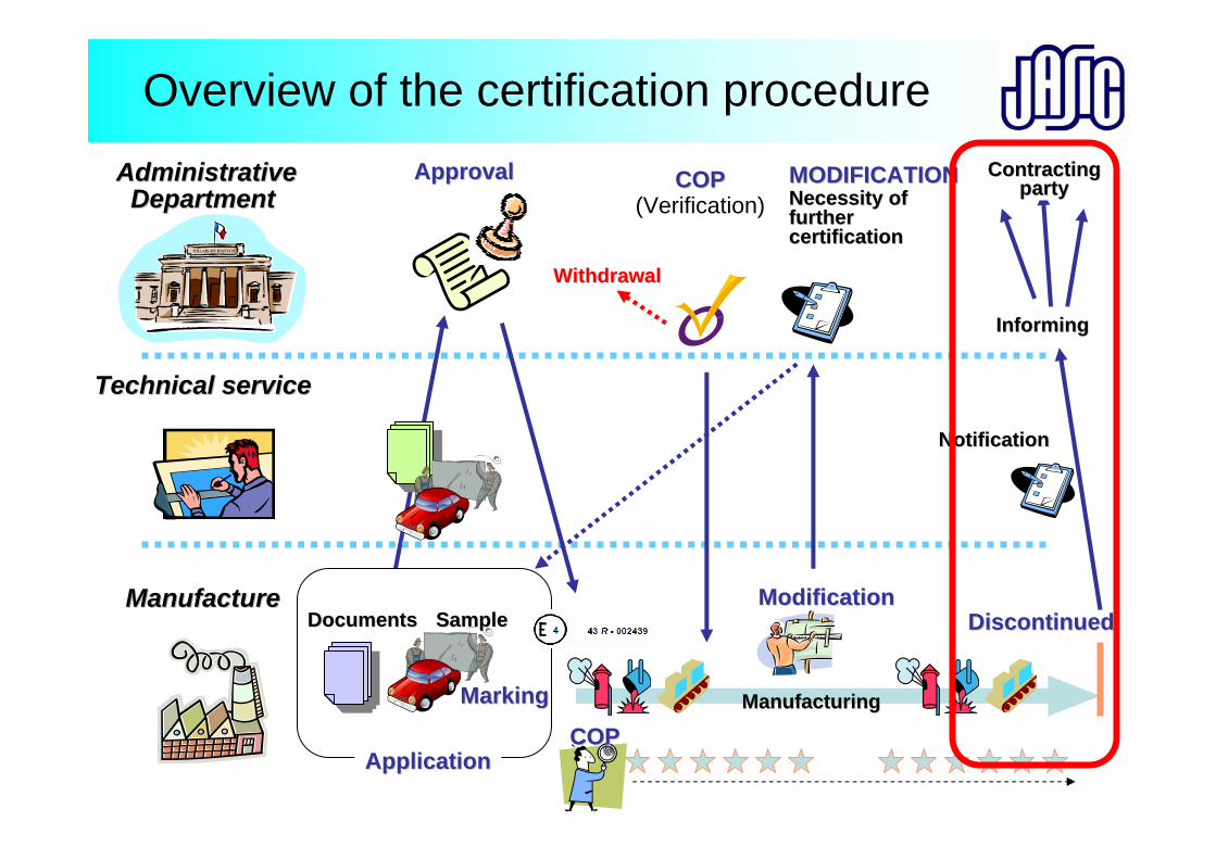
Overview of the certification procedureAdministrativeAdministrative
Department Department
Technical service Technical service
Manufacture Manufacture
ApplicationApplication
ApprovalApproval
COPCOP
COPCOP(Verification)
ModificationModification
ManufacturingManufacturing
MODIFICATIONMODIFICATIONNecessity ofNecessity offurtherfurthercertificationcertification
MarkingMarking
DiscontinuedDiscontinuedSampleSampleDocumentsDocuments
NotificationNotification
InformingInforming
ContractingContractingpartyparty
WithdrawalWithdrawal
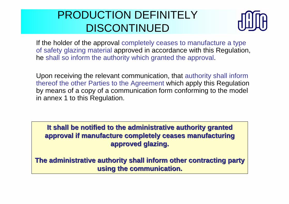
PRODUCTION DEFINITELY DISCONTINUED
If the holder of the approval completely ceases to manufacture a type of safety glazing material approved in accordance with this Regulation, he shall so inform the authority which granted the approval.
Upon receiving the relevant communication, that authority shall inform thereof the other Parties to the Agreement which apply this Regulation by means of a copy of a communication form conforming to the model in annex 1 to this Regulation.
It shall be notified to the administrative authority granted It shall be notified to the administrative authority granted approval if manufacture completely ceases manufacturing approval if manufacture completely ceases manufacturing
approved glazing.approved glazing.
The administrative authority shall inform other contracting partThe administrative authority shall inform other contracting party y using the communication.using the communication.
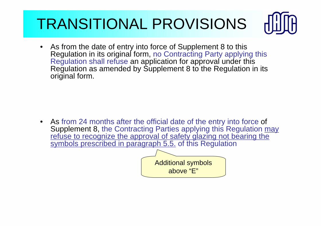
TRANSITIONAL PROVISIONS• As from the date of entry into force of Supplement 8 to this
Regulation in its original form, no Contracting Party applying this Regulation shall refuse an application for approval under this Regulation as amended by Supplement 8 to the Regulation in its original form.
• As from 24 months after the official date of the entry into force of Supplement 8, the Contracting Parties applying this Regulation may refuse to recognize the approval of safety glazing not bearing the symbols prescribed in paragraph 5.5. of this Regulation
Additional symbols above “E”

Thank you for your attention.
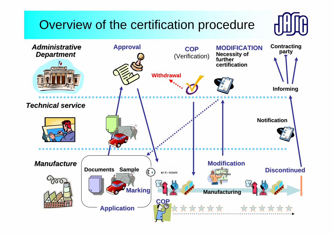
Overview of the certification procedureAdministrativeAdministrative
Department Department
Technical service Technical service
Manufacture Manufacture
ApplicationApplication
ApprovalApproval
COPCOP
COPCOP(Verification)
ModificationModification
ManufacturingManufacturing
MODIFICATIONMODIFICATIONNecessity ofNecessity offurtherfurthercertificationcertification
MarkingMarking
DiscontinuedDiscontinuedSampleSampleDocumentsDocuments
NotificationNotification
InformingInforming
ContractingContractingpartyparty
WithdrawalWithdrawal
ECE R43Safety Glazing
Asia Expert Meeting
1
Masaru MorikawaJASIC
PURPOSE
The glazing should have a safe performance during the vehicle in use
R43
2
SCOPESafety glazing materials:
Category L,M,N,O,T
Installation:Category M,N,O
Exclusion of ;・Glazing for lighting ・Light-signalling devices・Instrument panels ・Double windows・Bullet-proof glazing
R43
3
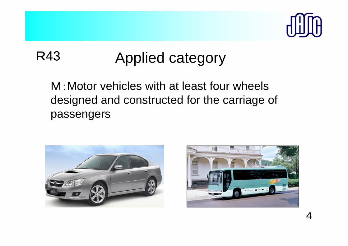
M:Motor vehicles with at least four wheels designed and constructed for the carriage of passengers
R43 Applied category
4
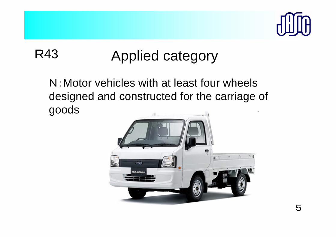
N:Motor vehicles with at least four wheels designed and constructed for the carriage of goods
R43 Applied category
5
L:Motor vehicles with less than four wheels
O:Trailers
T:Agricultural and forestry tractors
R43 Applied category
6
REQUIREMENTS
1.General requirements2. Installation on vehicles3.Safety glazing performance
R43
7
1.GENERAL REQUIREMENTS
1.Reduce the danger of body injury in the event of shuttering
2.Sufficiently resistant in normal traffic,temperature,chemical, abrasion
3.Sufficiently transparent
R43
8
3.INSTALLATION ON VEHICLES
Purpose
Ensure the driver with a high degree of visibility in all traffic conditions
R43
9
The light transmittance : not less than 70%
※Amendments (75%→70%)has been approved by WP29 (2008.Nov.)
R433.INSTALLATION ON VEHICLES
WINDSCREENS
10
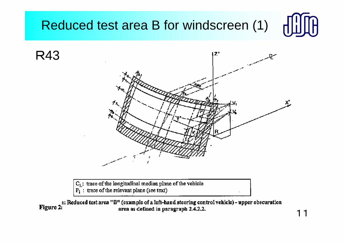
Reduced test area B for windscreen (1)
R43
11
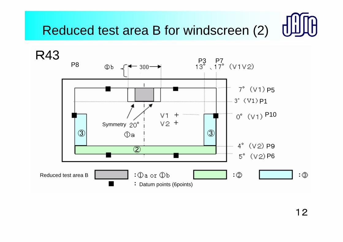
Reduced test area B for windscreen (2)
Symmetry
Reduced test area B
Datum points (6points)
②
③③
R43
P10
P5
P6
P7P8
P1
P9
P3
12
R43
13
R43
14
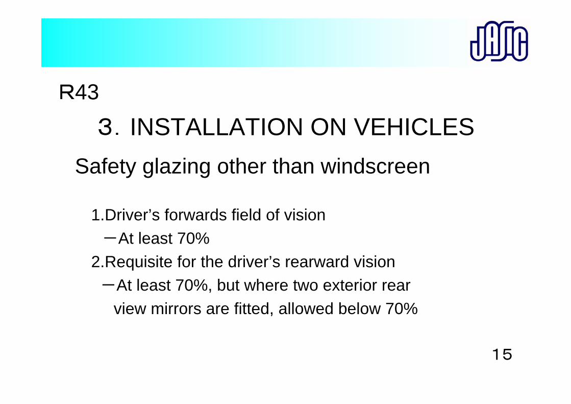
1.Driver’s forwards field of vision-At least 70%
2.Requisite for the driver’s rearward vision-At least 70%, but where two exterior rear
view mirrors are fitted, allowed below 70%
R433.INSTALLATION ON VEHICLES
Safety glazing other than windscreen
15
ECE R43Technical Requirement
and Testing Method for Glass
Asia Expert Meeting
Masaru MorikawaJASIC

Type of glass for Automotive (Laminated Glass and Toughened Glass)
Laminated glass is used for Windscreen
Laminated glass or Toughened glass are used for
Glass panes other than windscreens
(M、N category)
Type of glass in R-43
:Laminated glass :Toughened glass : Toughened glass : Laminated glass :Treated laminated glass :Glass plastics :Glass plastics
Windscreen Glass panes other than windscreens
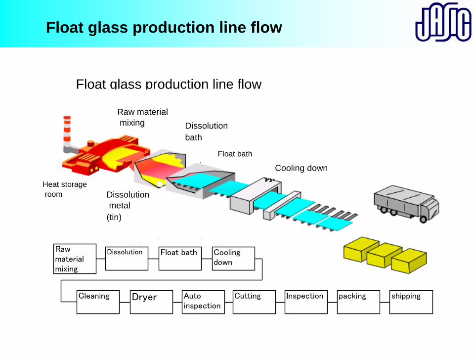
Float glass production line flow
Float glass production line flow
Rawmaterialmixing
Dissolution Float bath Coolingdown
Cleaning Dryer Cutting packingInspectionAutoinspection
shipping
Raw material mixing Dissolution
bath
Float bath
Cooling down
Heat storageroom Dissolution
metal(tin)
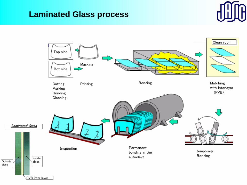
Laminated Glass process
Laminated Glass
Outsideglass
Insideglass
PVB Inter layer
Top side
Bot sideMasking
CuttingMarkingGrindingCleaning
Printing Bending
Clean room
Matchingwith interlayer (PVB)
temporaryBonding
Permanentbonding in theautoclave
Inspection
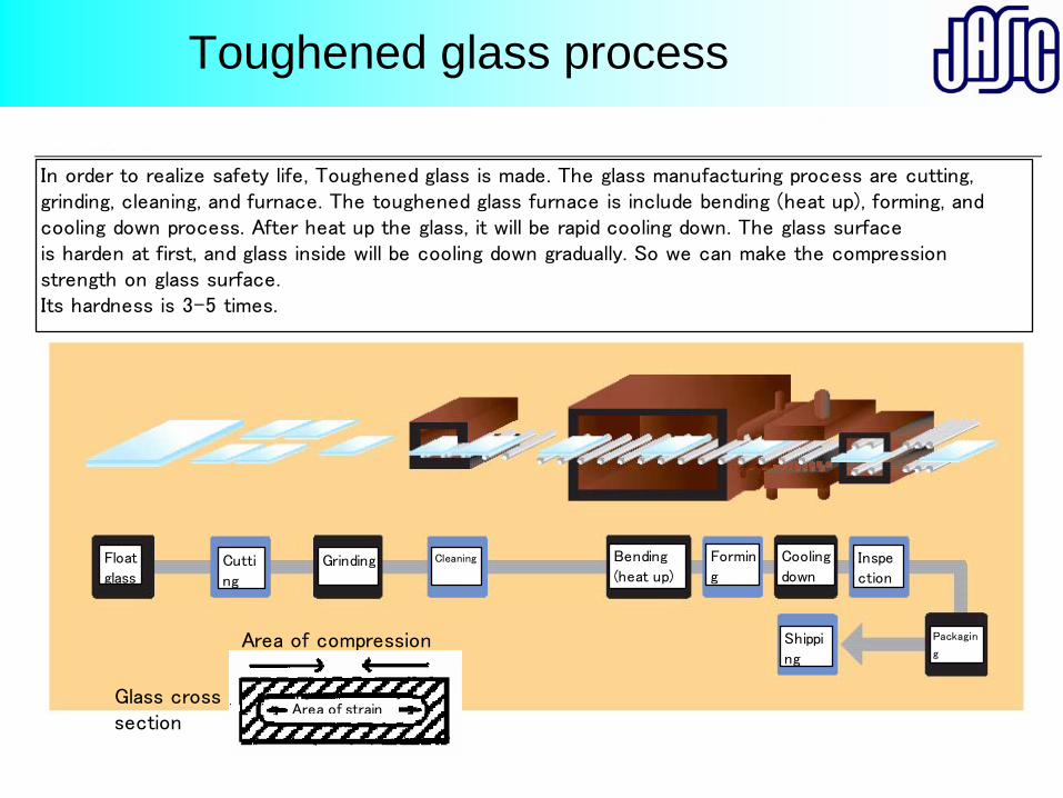
Toughened glass process
Float
glassCutti
ng
Grinding Cleaning Bending
(heat up)
Cooling
downInspe
ction
Packagin
gShippi
ng
Formin
g
In order to realize safety life, Toughened glass is made. The glass manufacturing process are cutting,grinding, cleaning, and furnace. The toughened glass furnace is include bending (heat up), forming, andcooling down process. After heat up the glass, it will be rapid cooling down. The glass surfaceis harden at first, and glass inside will be cooling down gradually. So we can make the compressionstrength on glass surface.Its hardness is 3-5 times.
Area of compression
Area of strainGlass crosssection
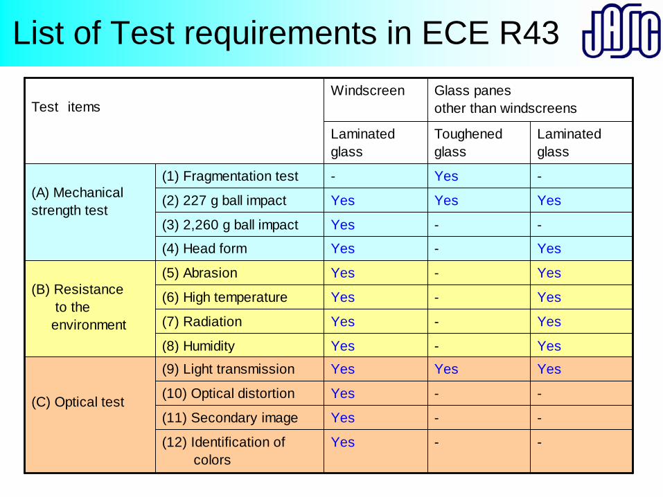
List of Test requirements in ECE R43
-Yes-(1) Fragmentation test
Glass panesother than windscreens
WindscreenTest items
Laminatedglass
Toughenedglass
Laminatedglass
YesYesYes(2) 227 g ball impact(A) Mechanicalstrength test
--Yes(3) 2,260 g ball impact
Yes-Yes(4) Head form
Yes-Yes(5) Abrasion(B) Resistance to the environment
Yes-Yes(6) High temperature
Yes-Yes(7) Radiation
Yes-Yes(8) Humidity
YesYesYes(9) Light transmission
(C) Optical test --Yes(10) Optical distortion
--Yes(11) Secondary image
--Yes(12) Identification of colors
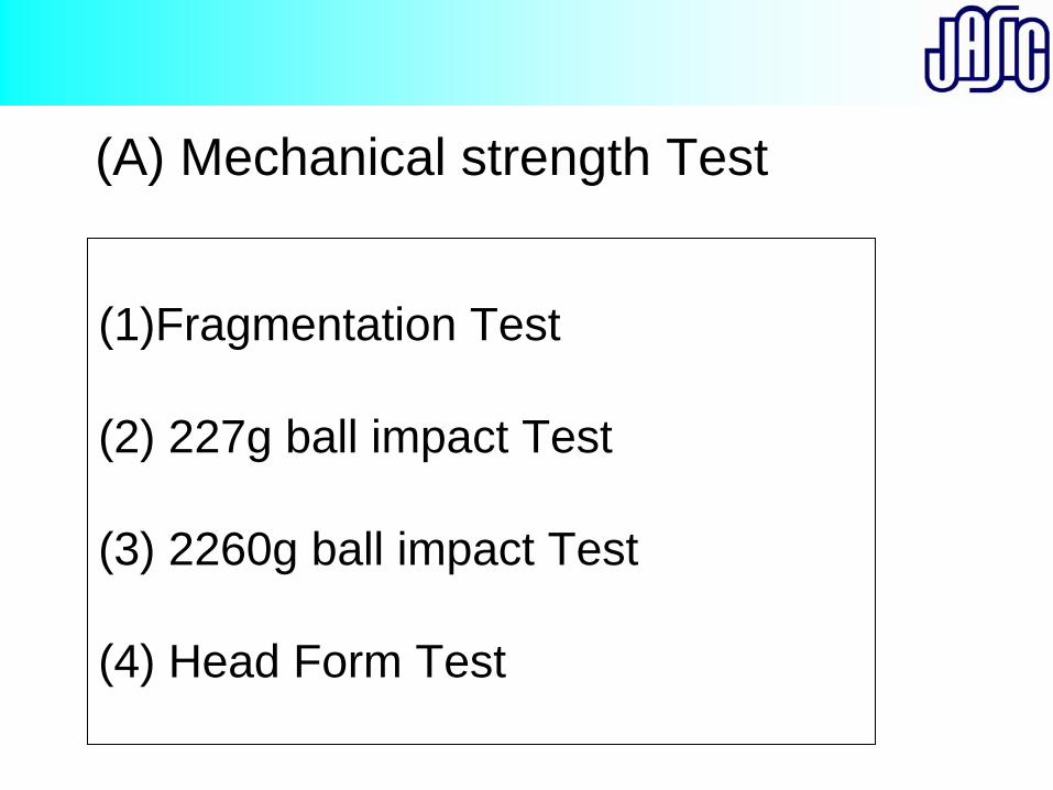
(A) Mechanical strength Test
(1)Fragmentation Test
(2) 227g ball impact Test
(3) 2260g ball impact Test
(4) Head Form Test
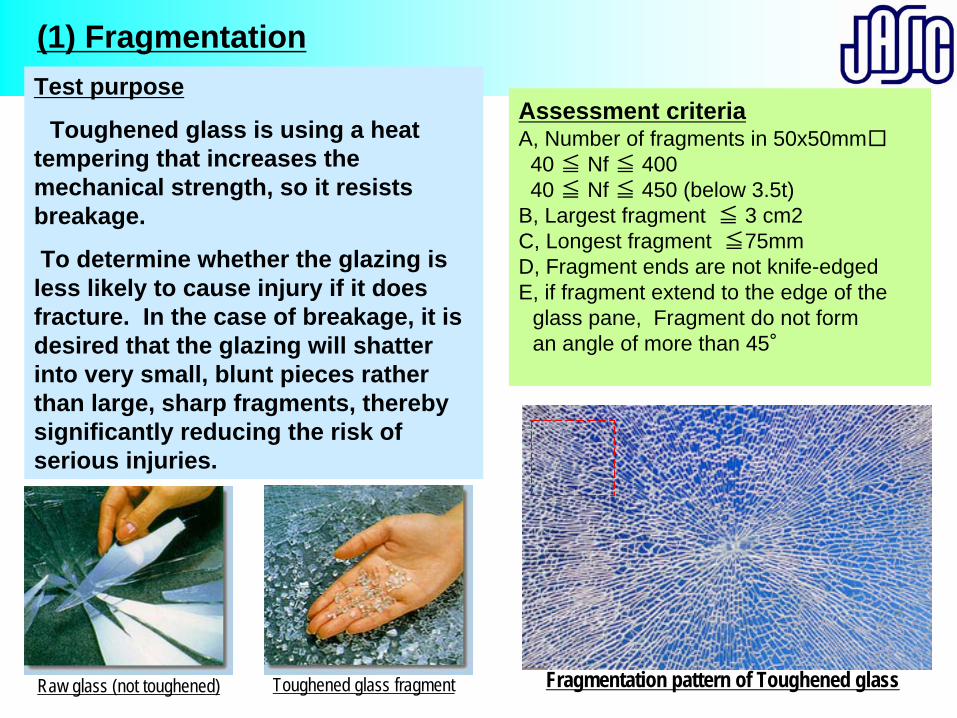
(1) Fragmentation
Fragmentation pattern of Toughened glass
Assessment criteriaA, Number of fragments in 50x50mm□
40 ≦ Nf ≦ 40040 ≦ Nf ≦ 450 (below 3.5t)
B, Largest fragment ≦ 3 cm2 C, Longest fragment ≦75mmD, Fragment ends are not knife-edgedE, if fragment extend to the edge of the
glass pane, Fragment do not form an angle of more than 45°
Raw glass (not toughened) Toughened glass fragment
Test purpose
Toughened glass is using a heat tempering that increases the mechanical strength, so it resists breakage.
To determine whether the glazing is less likely to cause injury if it does fracture. In the case of breakage, it is desired that the glazing will shatter into very small, blunt pieces rather than large, sharp fragments, thereby significantly reducing the risk of serious injuries.
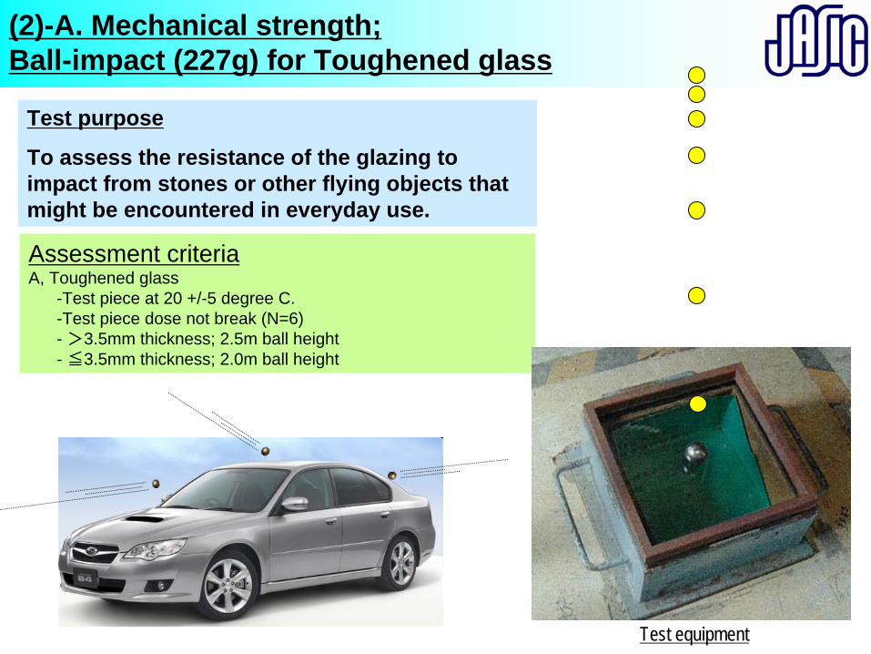
(2)-A. Mechanical strength; Ball-impact (227g) for Toughened glass
Test purpose
To assess the resistance of the glazing to impact from stones or other flying objects that might be encountered in everyday use.
Assessment criteriaA, Toughened glass
-Test piece at 20 +/-5 degree C.-Test piece dose not break (N=6)- >3.5mm thickness; 2.5m ball height- ≦3.5mm thickness; 2.0m ball height
Test equipment
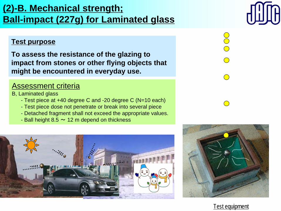
Test purpose
To assess the resistance of the glazing to impact from stones or other flying objects that might be encountered in everyday use.
(2)-B. Mechanical strength; Ball-impact (227g) for Laminated glass
Assessment criteriaB, Laminated glass
- Test piece at +40 degree C and -20 degree C (N=10 each)- Test piece dose not penetrate or break into several piece- Detached fragment shall not exceed the appropriate values.- Ball height 8.5 ~ 12 m depend on thickness
Test equipment
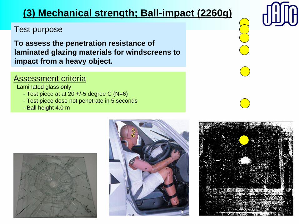
Test purposeTo assess the penetration resistance of laminated glazing materials for windscreens to impact from a heavy object.
(3) Mechanical strength; Ball-impact (2260g)
Assessment criteriaLaminated glass only
- Test piece at at 20 +/-5 degree C (N=6)- Test piece dose not penetrate in 5 seconds- Ball height 4.0 m
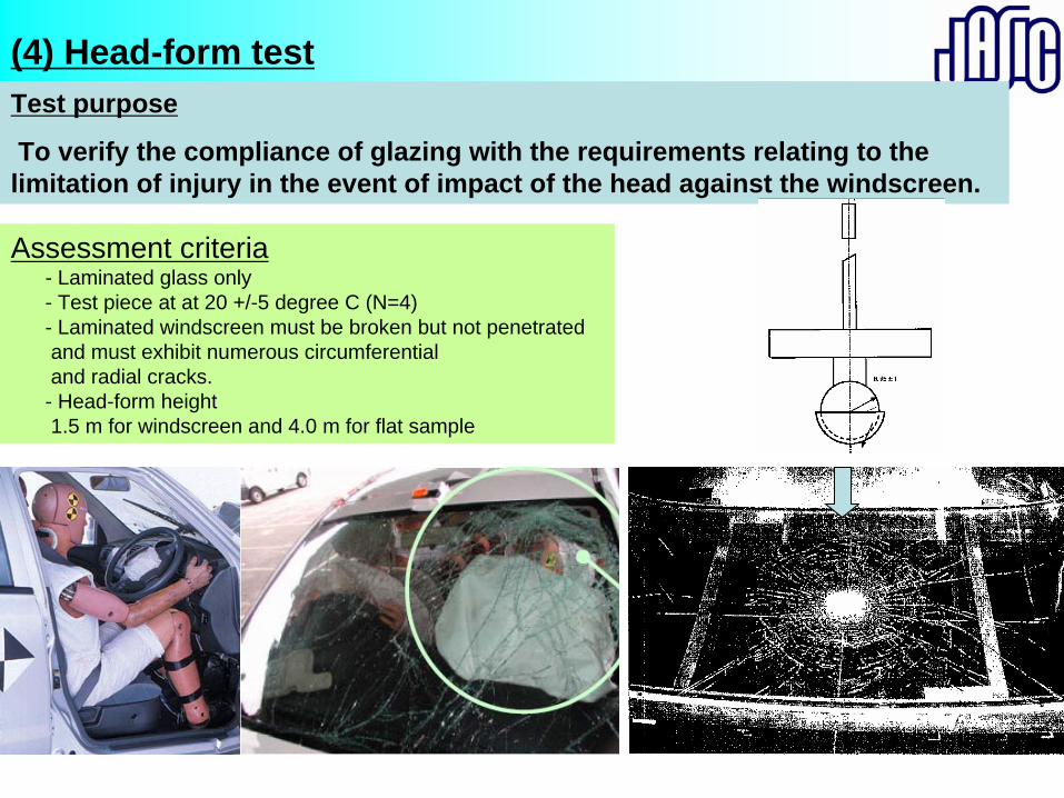
Test purpose
To verify the compliance of glazing with the requirements relating to the limitation of injury in the event of impact of the head against the windscreen.
(4) Head-form test
Assessment criteria- Laminated glass only- Test piece at at 20 +/-5 degree C (N=4)- Laminated windscreen must be broken but not penetratedand must exhibit numerous circumferentialand radial cracks. - Head-form height 1.5 m for windscreen and 4.0 m for flat sample
(B) Resistance to the environment Test
(5) Abrasion Test
(6) High temperature Test
(7) Radiation Test
(8) Humidity Test
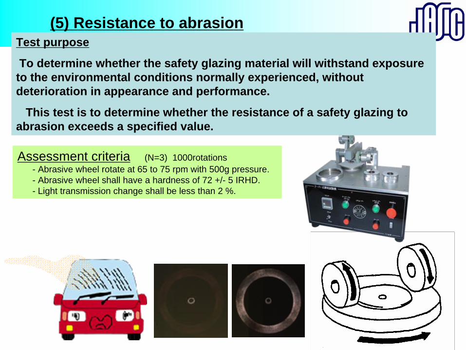
Test purpose
To determine whether the safety glazing material will withstand exposure to the environmental conditions normally experienced, without deterioration in appearance and performance.
This test is to determine whether the resistance of a safety glazing to abrasion exceeds a specified value.
(5) Resistance to abrasion
Assessment criteria (N=3) 1000rotations- Abrasive wheel rotate at 65 to 75 rpm with 500g pressure.- Abrasive wheel shall have a hardness of 72 +/- 5 IRHD.- Light transmission change shall be less than 2 %.
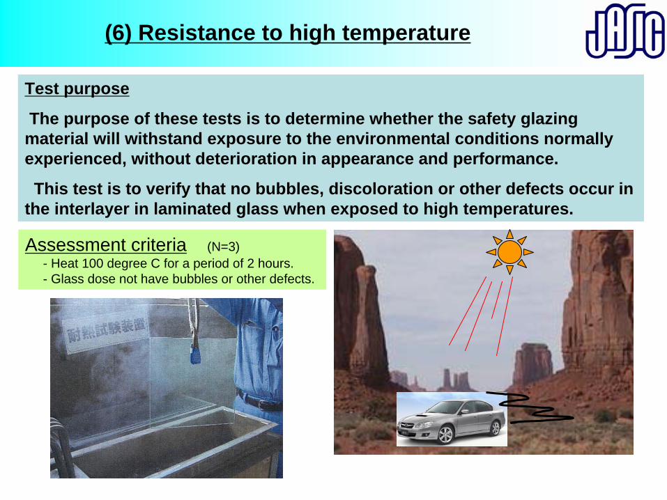
Test purpose
The purpose of these tests is to determine whether the safety glazing material will withstand exposure to the environmental conditions normally experienced, without deterioration in appearance and performance.
This test is to verify that no bubbles, discoloration or other defects occur in the interlayer in laminated glass when exposed to high temperatures.
(6) Resistance to high temperature
Assessment criteria (N=3)- Heat 100 degree C for a period of 2 hours.- Glass dose not have bubbles or other defects.
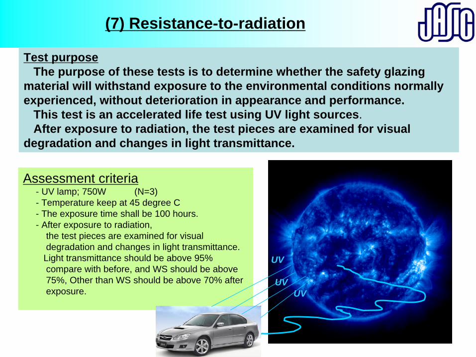
(7) Resistance-to-radiation
Test purposeThe purpose of these tests is to determine whether the safety glazing
material will withstand exposure to the environmental conditions normally experienced, without deterioration in appearance and performance.
This test is an accelerated life test using UV light sources.After exposure to radiation, the test pieces are examined for visual
degradation and changes in light transmittance.
Assessment criteria- UV lamp; 750W (N=3)- Temperature keep at 45 degree C - The exposure time shall be 100 hours.- After exposure to radiation,
the test pieces are examined for visualdegradation and changes in light transmittance.Light transmittance should be above 95% compare with before, and WS should be above 75%, Other than WS should be above 70% after exposure.
UV
UVUV
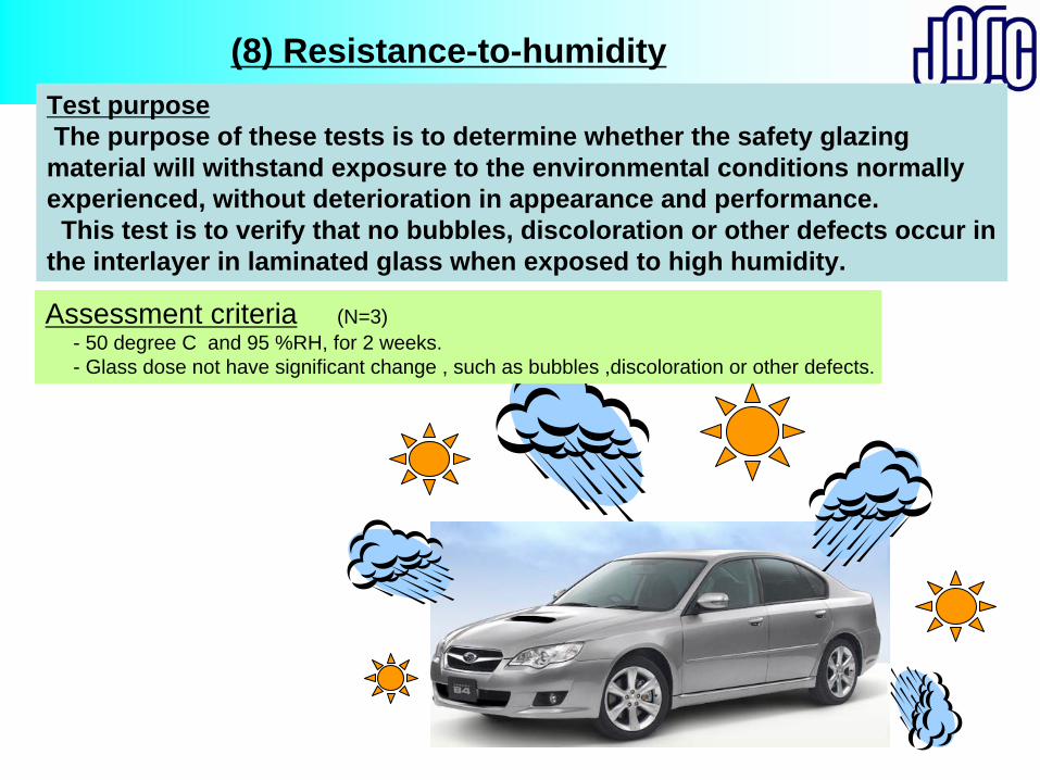
Test purposeThe purpose of these tests is to determine whether the safety glazing material will withstand exposure to the environmental conditions normally experienced, without deterioration in appearance and performance. This test is to verify that no bubbles, discoloration or other defects occur in
the interlayer in laminated glass when exposed to high humidity.
(8) Resistance-to-humidity
Assessment criteria (N=3)- 50 degree C and 95 %RH, for 2 weeks.- Glass dose not have significant change , such as bubbles ,discoloration or other defects.
(C) Optical Test
(9) Light transmission Test
(10) Optical distortion Test
(11) Secondary image Test
(12) Identification of colours Test
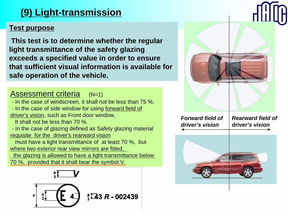
Test purpose
This test is to determine whether the regular light transmittance of the safety glazing exceeds a specified value in order to ensure that sufficient visual information is available for safe operation of the vehicle.
(9) Light-transmission
Assessment criteria (N=1)- In the case of windscreen, it shall not be less than 75 %.- In the case of side window for using forward field of
driver’s vision, such as Front door window, It shall not be less than 70 %.
- In the case of glazing defined as Safety glazing material requisite for the driver's rearward vision
must have a light transmittance of at least 70 %, but where two exterior rear view mirrors are fitted,
the glazing is allowed to have a light transmittance below 70 %, provided that it shall bear the symbol V.
Forward field of driver’s vision
Rearward field of driver’s vision
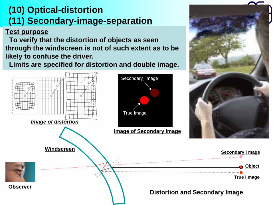
Test purposeTo verify that the distortion of objects as seen
through the windscreen is not of such extent as to be likely to confuse the driver.Limits are specified for distortion and double image.
(10) Optical-distortion (11) Secondary-image-separation
Image of distortion
Object
True I mage
Secondary I mage
Distortion and Secondary Image
True Image
Secondary Image
Image of Secondary Image
Windscreen
Observer
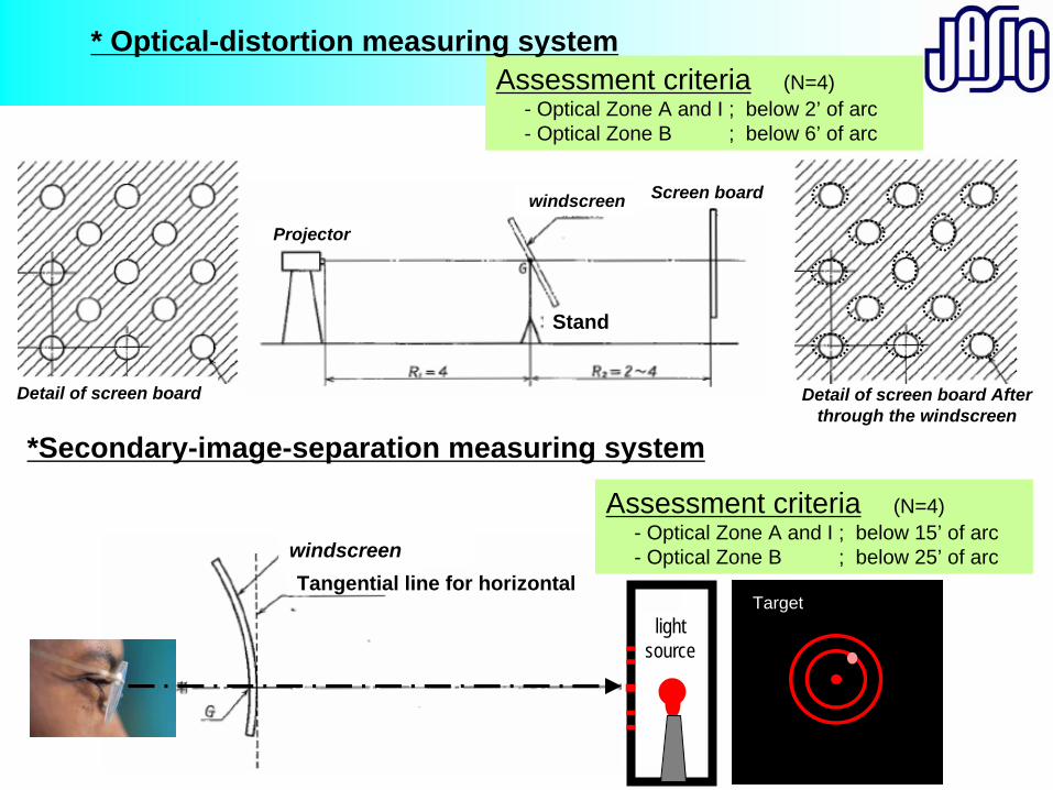
Assessment criteria (N=4)- Optical Zone A and I ; below 2’ of arc- Optical Zone B ; below 6’ of arc
Projector
windscreen Screen board
Detail of screen board After through the windscreen
Detail of screen board
Targetlight
source
windscreen
* Optical-distortion measuring system
*Secondary-image-separation measuring system
Assessment criteria (N=4)- Optical Zone A and I ; below 15’ of arc- Optical Zone B ; below 25’ of arc
Tangential line for horizontal
Stand
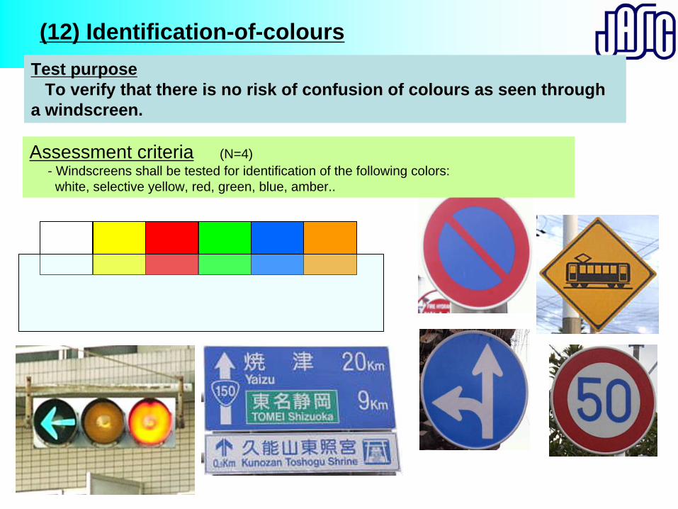
Test purposeTo verify that there is no risk of confusion of colours as seen through
a windscreen.
(12) Identification-of-colours
Assessment criteria (N=4)- Windscreens shall be tested for identification of the following colors:
white, selective yellow, red, green, blue, amber..

Thank you for your attention
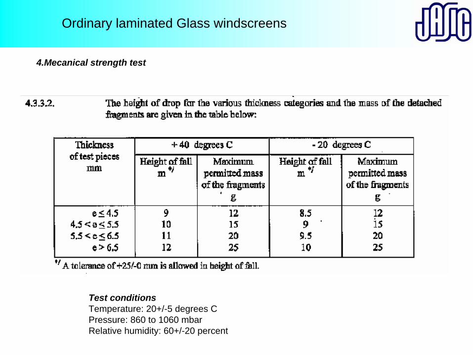
Ordinary laminated Glass windscreens
4.Mecanical strength test
Test conditionsTemperature: 20+/-5 degrees CPressure: 860 to 1060 mbarRelative humidity: 60+/-20 percent
第 21回アジア専門家会議概要報告
「ECE R41,ECE R51(騒音)、ECE R43 (安全ガラス)に関する専門家会議 日時:2009 年 10 月 1,2 日 場所: LTO 会議室@フィリピン ケソン 出席:各省庁、業界団体から約 60 名
JASIC:白橋、米澤、守川、福田 議事: <1日目>
・ECE R41(二輪車)、R51(乗用車)について
(白橋、米澤氏:JASIC 騒音分科会)
初めに白橋氏から車両カテゴリー、騒音規制の歴史、基準構成、申請認可、COP等の
概要、次に米澤氏から ECE R41、白橋氏から ECE R51 の要件と試験方法について詳
細にビデオも使い説明を行いました。参加者から次のような質問があり、UNECE 規則の
理解を深める貴重な会議となりました。
(主な質問) 1. ECEレギュレーションで言う認証機関は、政府か第三者か? Ans:ECE では、認証試験を行うのは、第三者機関です。試験結果に基づいて認可を
与えるのが政府機関になります。 2. マフラー内にグラスウールを使用している場合に耐久要件があるが、マフラーにア
スベストを使っている場合は、何か規定があるか?(二輪マフラー業界?) Ans:アスベストは先進国のほとんどで使用禁止物質となっており、ECE の中では、
その使用を前提の規定はありません。使用されないものとの認識です。 3. 排ガス規制のEuro2と騒音規制のバージョンとの対応を知りたい? Ans:騒音規制の 新 Ver は R41-03 になります。Euro2、Euro3 の切替タイミングと
R41-02、R41-03 のタイミングが異なります。 Euro3 車両は、すべて R41-03 対応です。 Euro2 車両は、R41-02,R41-03 の両方が存在します。 4. EURO2 システム、EURO 燃料で、R51/02 の達成が可能か。 Ans:今までの経緯では、排ガス規制、騒音規制は連動してバージョンアップしてきて
いる。組み合わせを変えた場合は、あらたな開発が必要になることになる。その経験が
ないので、今、回答できない。 5. 騒音試験実施前に充分暖気する事との記述があるが、「何度」というように絶対値で
の規定がないのか? Ans:絶対値の規定はありません。EG の水温、油温等が安定した状態を、『十分に暖気
された』と考えます。 また、熱帯地域のフィリピンでは、何度にして試験を実施すればよいか?
Ans:絶対値の温度での規定はなく、安定した騒音データの測定が目的であるので、騒
音データに変化がなくなればよい。例えば車載の水温計も目安になる。 6. R41/R51ともに加速騒音試験と近接排気騒音試験を実施しすることになって
いるが、どちらの試験がよりよいか?(DOTC) Ans:どちらの試験法が良いかではなく、目的に応じて試験方法を使い分ける。車両認
証の試験としては、車両全体騒音を評価する加速騒音試験の結果によって行います。加
速騒音試験は必須事項です。排気騒音の変化を使用過程車両の取り締まり等で行わない
のであれば、近接は不要です。(近接試験は、使用過程車両の排気管劣化や損傷による
騒音増大、交換マフラー等の取り締まりを目的に参考値として、オリジナル車両データ
として取得しています。) 7. 何か、フィリピン政府に提案があるか? Ans:ECE-R41 については、変更なしに取り入れられることを希望します。また、路
上等での使用過程車、交換マフラー取り締まりも近接排気騒音の相対値を使用した制度
をお勧めします。(絶対値より、相対値の方が捕捉効果が高く、論理的にも説明可能な
内容です。) 8. 日本では、使用過程車への騒音規定があるか? Ans:あります。2010 年 4 月以降、マフラーの部品認証制度が運用となります。 9. 基本的な質問で恐縮だが、「なぜ、騒音規制が必要であるのか?」(DOTC) Ans:住民が静かな環境での生活できることを保障する上で、騒音の発生源対応の結果、
道路交通における騒音改善には、騒音規制が求められています。道路交通における騒音
は、車両の加速騒音が基本的に寄与していると考えられ、加速騒音を測定し、それを規
制の中に納めることで、環境騒音を低減することが可能になります。 10. ECE では、どのように騒音の規制値をきめたのか?(DOTC) Ans:現在の法規が改定されたのが 14 年前のことであり、このときのことは、わから
ないが、一般的には、環境騒音から求められる騒音規制の検討と、現状の騒音低減技術
の検討を協議するなかで、GRB 会議の中で技術検討がなされ、WP29 の討議で各国政
府当局によって、決定されてきました。 <2日目>
・UNECE R43(安全ガラス)について (守川:JASIC 一般安全分科会)
初めにUNECER43(安全ガラス)基準の申請から認可、その後の変更申請、CO
P等の認証取得手順概要、次に安全ガラスの適用カテゴリ及び車両取り付け、 後に各
種安全ガラスの製造方法を含めて試験要件、試験方法等の詳細説明を行いました。参加
者から次のような質問があり、UNECE 規則の理解を深める貴重な会議となりました。
(主な質問) 1.試験環境についてフィリピンは暑いが? Ans:温度など環境が指定されているので従う必要がある。 環境をコントロールした状態で試験できるように。 2.強度試験では、何故実際の車でテストしないのか? Ans:スレッドテストなどでの結果から現在の試験が決まっている。 3.フィルムの貼り付けはどう考える? Ans:R43 では前面ガラスなどは NG となる。 4.衝突物はいろいろあると思うが、何故球なのか? Ans:球で代表できると判断した。 以上