ductile iron society research committee report compiled by ... · ductile iron society research...
TRANSCRIPT

Ductile Iron Society RESEARCH PROJECT No. 47
Literature Summary: Deteriorated Graphite in Casting Surfaces
Ductile Iron Society
Research Committee Report
Compiled by Doug White - Elkem
DUCTILE IRON SOCIETY
Issued by the Ductile Iron Society for the use
of its Member Companies – Not for General Distribution
DUCTILE IRON SOCIETY 15400 Pearl Road, Suite 234 Strongsville, Ohio 44136
(440) 665‐3686
JANUARY 2012
Ductile Iron Society- Research Committee Report
literature Summary: Deteriorated Graphite in Casting Surfaces
SUMMARY
DIS Research has shown that a considerable drop in the fatigue life of ductile iron
castings occurs when there are surface defects or deteriorated graphite in the
skin of castings. Papers demonstrate this can be due to reactions with the mold or
cores due to the presence of S from seacoal or binder systems, oxygen such as
moisture in greensand, or N bearing gases from some sand binder systems.
Other researchers have studied additional surface quality issues that impact
properties.
Means to minimize or eliminate these issues have been proposed.
DIS Hot Topic articles and DIS Research reports are available to members on the
DIS website.
AFS Transaction papers will be available to people who have previously purchased
AFS Transactions. Other AFS literature such as Modern Casting articles or copies
of AFS Transaction papers may be obtained by contacting AFS.
Doug White: Technical Service Manager, Elkem Materials, Inc. January 2012
Literature search -
Deteriorated Graphite Structures on Cast Iron Skins.
DIS Literature
DIS Research Project No. 17 Sulfur in Molding Sand Effect on Flake Graphite at the Cast Surface of
Ductile Iron Castings George DiSylvestro and Robert Christ
Ductile Iron Society Research Report No. 44 Effect of Surface Defects on Fatique properties of Ferritic
Ductile Iron, Rick Gundlack (Stork Climax Research Services) and John McGoldrick (Hodge Foundry, Inc.)
Ductile Iron Society Research Project No. 45 Graphite Shape Degredation at the Surface of Chemically
Bonded Sand Molds and Cores.
DIS Hot Topic #7- 2004 Improving Fatigue Strength (Jim Mullins)
DIS Hot Topic #3- 2004 Surface Treatments for Ductile Iron (Eugene Muratore)
DIS Hot Topic #7- 2008 Abnormal Surface Microstructures (AI Alagarsamy)
Powerpoint Presentation - DIS Meeting June 2011- Lundeen (Foseco)
AFS Literature
Boonmee, S., Gyesi, B., Stefanescu, D., "Casting Skin of Compacted Graphite Iron, Part 1: Evaluation and
Mechanism of Formation," Transactions of the American Foundry Society, Vol. 118, pp. 205-216 (2010)
Boonmee, S., Stefanescu, D., "Casting Skin of Compacted Graphite Iron, Part II: Influence on Tensile
Mechanical Properties, ({Transactions of the American Foundry Society, Vol. 118, pp. 217-224 (2010)
Stefanescu, D.M., Wills, S., Massone, J., Duncan, F., "Quantification of Casting Skin in Ductile and
Compacted Graphite Irons and Its Effect on Tensile Properties," Transactions of the American Foundry
Society, Vol. 117, pp. 587-606 (2009)
Stefanescu, D.M., Juretzko, F.R., "Study ofthe Effect of Some Process Variables on the Surface
Roughness and the Tensile Properties of Thin Wall Ductile Iron Castings," Transactions of the American
Foundry Society, Vol. 115, pp. 637-646 (2007)
Martin, F., Karsay, S. 1., "Localized Flake Graphite Structure as a Result of a Reaction Between Molten
Ductile Iron and Some Components in the Mold," Transactions of the American Foundrymen's Society,
Vol. 87, pp. 221-226 (1979)
Duncan, F.C., Kraker, J., "A New Test Casting to Evaluate Skin Formation in CGI, "Proceedings of the
American Foundry Society, 11Sth Metalcasting Congress, paper 10-023 (2011)
Goodrich, G., "Effect of Cooling Rate on Pearlitic Ductile Iron Mechanical Properties," PowerPoint®
presentations, copyright ©American Foundry Society (2007)
La Fay, V.S., Neltner, S.L., "Drifting Away from Seacoal," Modern Casting, Vol. 94, No. 12, pp. 28-30,
(December 2004)
Torrance, J., Stefanescu, D., " Investigation of the Effect of Surface Roughness on the Static Mechanical
Properties of Thin Walled Ductile Iron Castings," Transactions of the American Foundry Society, Vol. 112,
pp. 757-772 (2004)
Tinebra, J.P., Wilson, S.J., "Nobake Chemical Binder Systems: Their Effect on Microstructural and
Physical Properties of Ductile Iron," Transactions of the American Foundrymen's Society, Vol. 101, pp.
169-173 (1993)
Xiaogan, H., Jin, X., Wenqing, W., Xuqi, D., Yaoke, W., "Nodular Iron Surface Deterioration Due to PTSA in
Resin," Transactions of the American Foundrymen's Society, Vol. 100, pp. 9-15 (1992)
Kambayashi, H; Une, H; Kurokawa, Y; Ito, T; Mikamoto, S; Miyake, H., "Mold Surface Analysis Evaluation
of Inclusion Defects Occurring in Cast Iron Produced in Green Sand Molds," Transactions of the
American Foundry Society, Vol. 112, pp. 787-799 (2004)
Lawerenz, M., "Shot Peening Ductile Iron," Modern Casting, Vol. 80, No.2, pp. 51-53 (Feb 1990)
Watmough, T., Malatesta, M.J., "Strengthening of Ductile Iron for Crankshaft Applications," Transactions of the American Foundrymen's Society, Vol. 92, pp. 83-99 (1984)
Shrikhande, V., "Sulfur Control at the Mold/Metal Interface of Cast Ductile Iron," Modern Casting, Vol. 85, No. 1, p. 44 (Jan 1995)
Mampaey, F., Li, P.l. , Wettinck, E., "Variations in Strength along the Casting Diameter", "Transactions of the American Foundrymen's Society" 2003, AFS Library Copy 20030283A.pdf
Other literature
Influence of Surface Quality on Fatigue Behavior of Nodular Cast iron, M.Kokavec and R. Konecna
University of Zilina, Slovakia and G. Nicoletta University of Parma, Italy. Acta Metallurgica Slovaca,
volume 17, 2011, No.2, pp 99-105
The Mechanism of Formation of Casting Skin in CGI and its Effect on Tensile Properties, Boon me and
Stefa nescu www .scientific.net/KE M .457.11
Factors Influencing the Surface Graphite Degeneration in Ductil.e Iron Castings in Resin Mold Technology.
R.iposan, Chisamera, Stan, Skaland TSINGHUA Science and Technology ISSN 1007-0214 08/20 pp157-
163 Volume 13 Number 2 April 2008
Flake Graphite Layers at the cast Surfaces of Nodular Iron Castings. BCIRA Broadsheet 234
Private communication
A Comparison of the Fatigue Strength of Machined and As-Cast Surfaces of SG Iron, Starkey and
Irving, July 1982 Int'l Journal of Fatigue
Gray Iron Layer on Ductile Iron, Starkey and Irving, July 1982 Int'l Journal of Fatigue (not included)
SULFIJR IN MOLDING S&"''D uncr ON FLAKE GRAPHITE AT THE CAST SURFACE
OF DUCTILE IRON CASTINGS
Ductile Iron Society · ProjectP17
A Research Project of the Committee on Structmal Control
by
Project Direction - George Di Sylvestro Project Assistance- Amertcan Colloid Company
Project Summary - Robert J . Christ
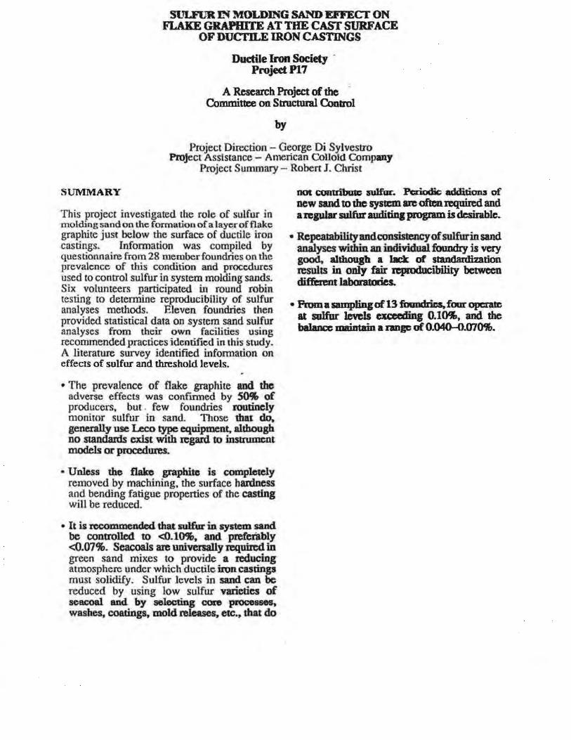
SUMMARY
This project investigated the role of sulfur in molding sand on the formation of a layer of flake graphite just below the ~-urface of ductile iron castings. Information was compiled by questionnaire from 28 member foundries on the prevalence of this condition and procedures used to control sulfur in system molding sands. Six volunteers participated in round robin resting to determine reproducibility of sulfur analyses methods. Eleven foundries then provided statistical data on system sand sulfur analyses from their own facilities using recommended practices identified in this study. A literature survey identified information on effec1s of sulfur and threshold levels.
• The prevalence of flake graphite and the adverse effects wns confmned by ~ ·of producers, but . few foundries routinely monitor sulfur in sand. Those tbat do. generally use Leco type equipment. although no standaids exist with regard to instrument models or procedures.
• Unless the f1ako graphite is comple1dy removed by machining, the surface hardness and bending fatigue properties of the casting will be reduced.
• It is recommended that sulfur in system sand be controlled to <0.10%, and prefctably <0.07%. Scacoals are universally required in green sand mixes to provide a reducing atmosphere under which ductile iron castings must solidify. Sulfur levels in sand can be reduced by using low sulfur varieties of scacoal and by selecting core processos, washes, coatings, mold releases, etc., that do
DOl contdbullC P1fur. Pa:ioctic addi.ti0113 of new sand to the sysu:m are often required and a~gu)ar sulfur auditing program is desimblc.
• Rcpcal8bilityandconsistalcyofsulfurinsand analyses within an individual foundry is very good. although a lack of sta.ndaldi2ation results in only fair reproducibility between differatt laboratories.
• Prom a sampling of 13 foundries, four operate at sulfur JcveJs aaaling O.lK. and the balance maiDtain a DDF of 0.040-0.070CJ,.
DIS Research Project No. 44
DIS RESEARCH PROJECT NO. 44
EFFECT OF SURFACE DEFECTS ON FATIGUE PROPERTIES OF FERRITIC DUCTILE IRON
ABSTRACT
The fatigue strength offerritic ductile iron, Grade EN-GJS-400-18U-LT. was determined for large section castings measuring 4 by 24 by 24 inches. Fatigue testing was conducted in bending fatigue in order to determine the influence of surface conditions on fatigue strength. Test specimens with various surface conditions were evaluated, including notched and un-notched specimens, as well as those containing surface defects typical of heavy section ductile iron castings. In addition, smaller, round axial fatigue test specimens were tested to produce the more typical laboratory fatigue test properties for comparison with other materialS tested for the Ductile Iron Society.
Bending fatigue testing was conducted on two groups of specimens. A large number of specimens of intermediate size and obtained from the drag surface were tested to evaluate the effects of surface condition and notch sensitivity. Those specimens were nominally 1.6 in. thick by 2.0 in. wide by 12 inches long. Various notches were machined into the surface of the bars including U notches and V notches.
The second group of bars consisted of large test specimens measuring 3.1 by 3.5 by 24 inches long and which were obtained from the cope surface. Some of these test bars were prepared with hand-ground notches that are blended with the cast surface to simulate the normal repair conditions obtained in commercial castings after removing dross and slag indications.
Most of the testing was conducted at loads that produced failure so that the fatigue strength in the finite life region could be characterized. In this manner the sensitivity of the material to notches and surface defects could best be evaluated. Only a limited number of large fatigue bars could be tested, and fatigue testing in the finite life region was best for this reason.
Page2 of48
RES:EARCH PR·OJECT No. 45 Graphite Shape Degradation at the Surface of
Chemically ~onded Sand Molds and Cores.
AI Alagarsa,my
Consultant, BirJDinghaiD.z AL
Phillip B. Seaton Cheysler Gr6up, LLC, A"Q.burn Hills, Ml
DUCTILE IRON SOCIETY
Issued by the Ductile rron Society for the use of its Member Companies - Not for General Distribution
DUCTILE IRON SOCIETY 15400 Pearl Road, Suite 234
Strongsville, Ohio 44136 (440) 665-3686
JANUARY 2010

"The Influence of Coatings on the Graphite Structure in the Rim Zone of Ductile Iron Castings"
The results of the study has shown by the selection of the correct refractory filler combination, a coating
can be developed to prevent the effects of reversion to flake of ductile iron within the rim zone, due to
the sulfur content of the molding media (in particular sulfonic acid catalyzed systems). Dry coating layer
thickness of 0.20 to 0.25mm can help prevent reversion to flake with the rim zone where the mold
media contains up to 0.20% sulfur. The results indicate as the coating becomes saturated with sulfur, its
preventive mechanism is overcome and the sulfur level within the rim zone rises to above acceptable
levels. The effectiveness of the refractory coating is proportional to the amount of active ingredient
applied to the mold surface. This amount of active ingredient is directly proportional to the coating
layer thickness applied to the mold surface. By careful use of a Sulfur Block Coating, benefits can be
seen for the foundry, through increased use of reclaim sand (higher percentage of sulfur).
Contact Bruce Lundeen at Foseco for Foundry Practice 235
815 347-6864 Bruce.Lundeen@ Foseco.com
PowerPoint Presentation- DIS Annual Meeting, June 2, 2011, Dallas, Texas
Paper 10-467.pdf, Page 1 of 12 AFS Proceedings 2010 @ American Foundry Society, Schaumburg, IL USA
Casting Skin of Compacted Graphite Iron Part 1: Evaluation and mechanism of formation
S. Boonmee, B. Gyesi, D.M. Stefanescu The Ohio State University, Columbus, OH
Copyright 2010 American Foundry Society
ABSTRACT
The occurrence of the casting skin on iron castings is an undesirable feature that lowers mechanical properties compared to fully machined test samples. The purpose of this Part I of a two-part paper is to study the morphology of the casting skin for compacted graphite (CG) iron and to quantify its value as a function of some casting variables including molding sand, casting thickness (cooling rate), metallostatic height and shot blasting.
Virtual casting experiments with a commercial software were conducted to design a test casting based on specific requirements. After design criteria were met, two CG iron heats (carbon equivalent 4.44 and 4.54%) were produced through the ladle treatment process. The iron was cast in sodium silicate and phenolic-urethane bonded sand molds. A total of78 test castings were produced. The thickness of the cast test plate was 7.6mm (0.3in), 10.2mm (0.4in) and 15.2mm (0.6in).
The characterization perfonned on the test castings included graphite shape factors (nodularity), graphite area, percent of graphite and amount of pearlite using image analysis. In addition, the roughness average was evaluated on all samples. It was found that graphite shape factors vary as a function of distance from surface. After very low levels in the proximity of the surface, the nodularity increases and then gradually decreases toward the center of the plate casting. In addition, the percentage pearlite increases with distance from the surface. These quantities were used to define the casting skin. Casting skins ofO.OS to 0.39 mm were observed in these experiments.
The sodium silicate bonded molding aggregate produced higher roughness and thicker pearlitic rim than the phenolic-urethane bonded sand molds. Moreover, faster cooling rate tends to encourage graphite degradation. Finally, removal of the casting skin through shot blasting was observed when shot blasting time for 5 minutes.
Selected samples were further examined using a color metallography technique. The special etching outlined the interdendritic regions through the segregation of silicon
and was found to be a useful tool in the study of the casting skin.
Paper 10.068.pdf, Page 1 of 8 AFS Proceedings 2010@ American Foundry Society, Schaumburg, il USA
Casting Skin of Compacted Graphite Iron Part II: Influence on Tensile Mechanical Properties
S. Boonmee, D.M. Stefanescu The Ohio State University, Columbus, OH
Copyright 2010 American Foundry Society
ABSTRACT
The goal of this research was to assess the effect of casting skin on the tensile properties of compacted graphite (CG) iron produced by ladle treatment with magnesium and rare earth containing ferrosilicon. CG iron plate test castings were produced in sodium silicate and phenolic urethane nobake molds. The thickness of the plate castings was 7.6mm (0.3in), 10.2mm (0.4in) and 15.2mm (0.6in), corresponding to calculated cooling rates of 4, 8 and 12K/s, respectively. The visual nodularity of the plates was in the range of 5 to 20%, and the pearlite content varied from 6 to 26%.
Tensile testing was performed on as-cast samples, fully machined samples, and on samples that were not machined but were shot-blasted at two different levels (1 and 5 minutes). The tensile strength increased from an average of.300MPa for the as-cast plates to 355MPa for the machined plates. A similar trend was observed for elongation. Further improvement of the tensile properties was obtained through shot blasting. After five minutes of shot blasting the average strength increased to 392MPa. It was thus proved that shot blasting can be used to reverse the negative effects of the casting skin.
The maximum skin thickness observed in this research was of0.4mm. A tensile strength (TS) skin factor (SFrs) was defmed as the ratio between the TS on the as-cast specimens (having a casting skin) and the TS on the machined test plates. The average SFrs for all as-cast and machined specimens was 0.91. This means a 9% decrease in tensile strength because of the presence of the casting skin.
Regression analysis of the experimental data was used to generate equations to calculate the tensile strength as a function of the various quantities that define the casting skin and ofthe microstructure of the casting. The regression equations indicate that the tensile strength significantly decreases with higher roughness and skin thickness. The pearlitic rim slightly increases the strength. The phenolic urethane produces a less damaging skin than the sodium silicate. This resulted in a higher average tensile strength of 329MPa for the phenolic urethane ascast plates, compared to 311MPa for the sodium silicate plates.
Paper 09-120.pdf, Page 1 of 20 AFS Transactions 2009@ American Foundry Society, Schaumburg, IL USA
Quantification of Casting Skin in Ductile and Compacted Graphite Irons and Its Effect on Tensile Properties
D.M. Stefanescu, S. Wills, J. Massone The Ohio State University, Columbus Ohio
F. Duncan Ashland Casting Solutions, Columbus Ohio
Copyright 2009 American Foundry Society
ABSTRACT The mechanical properties of ductile (DI) and compacted graphite (CG) irons are measured and reported on standard machined specimens (as per ASTM). However, most castings retain most of the as-cast surface. This surface layer (the casting skin) includes both surface and subsurface features. Because of the casting skin, the mechanical properties of the part are typically significantly lower than those found on standard ASTM machined specimens.
The technical objectives of this research were to identify the individual features that together define skin quality in DI and CGI, to develop a method for the measurement of skin thickness, and to quantify the influence of the skin of thin wall (2 to 6 mm) DI castings on its tensile properties.
The features of the casting skin include surface (roughness) and subsurface (graphite degradation, graphite depletion, pearlitic rim) elements. Graphite shape measurements were used to evaluate graphite degradation. Graphite area measurements were used to determine the thickness of the graphite depleted layer. Microharc.hiess measurements are useful when a pearlitic rim occurs. The average thickness of the skin for thin wall DI castings ranged from 0.15 to 0.45mm, while for CGI it ranged from 0.7 to 2.5mm.
It was found as expected that the strength decreased with thicker casting skin. The tensile and yield strength skin factor (ratio between the strength of as-cast and machined test plates) was about 0.93. This should be viewed as an upper limit, as only one of the surfaces of the mechanical properties test plate was as-cast. More significant reduction in strength should be expected.
Diffusion calculations confrrmed that graphite degradation, graphite depletion and the pearlitic rim are the result of magnesium and carbon depletion at the mold/metal interface because of their oxidation. Alternatively, carbon diffusion from the mold can also result in pearlitic rim formation.
Paper 07 ·118(05).pdf, Page 1 of 9 AFS Transactions 2007@ American Foundry Society, Schaumburg, IL USA
Study of the Effect of Some Process Variables on the Surface Roughness and the Tensile Properties of Thin Wall Ductile Iron Castings
D.M. Stefanescu The Ohio State University, Columbus, Ohio
F .R. Juretzko The University of Alabama, Tuscaloosa, Alabama
~opyright 2007 American Foundry Society
ABSTRACT
The influence of a number of process variables, such as metallostatic height (8.5-18.5mm), sand grain fineness ( 42-97 GFN), pouring temperature ( l366-1469°C) and sand coating, on the tensile properties and surface roughness of thin-wall ductile iron (TWDI) castings was investigated. The test casting was a 3-plate vertical casting of thickness 6, 2.5 and 3.5 mm, poured in .resin-bonded molds. 'Extensive statistical analysis was conducted to evaluate the experimental results on 32 test-plates. It was found that the roughne.ss increased with the metallostatic height, and decreased with sand fmeness (higher AFS sand grain fineness number) and increased pouring temperature. Applying a mold coating decreased the average surfac.e roughness from 8.65 to 3.731Lfll, and furthermore decreased the standard deviation. The mechanical properties were consistently good, with the following averages: tensile strength- 62.5ksi, yield strength - 45.3ksi, and elongation- 12.6%. All mechanical properties increased with the metallostatic height and the pouring temperature. When properties were plotted against roughness, the strength increased as the roughness decreased. The coated plates exhibited the highest correlation coefficient for linear regression, which means improved consistency. Also, the data were more consistent for the plates produced under high metallostatic pressure.
l.ocalized Flake Graphi~e Structure as-.a Result of a Reaction Between Molten Ductile Iron and Some Components of the Mold
F. Martin, Te~hnlcal Dirt>ctor Lujkin Industries Ltdkin. Texas S. l. Karsay. Chief FoundrJ' Metallurgist QIT-Fer et ntane Inc. Sorel. Quebec. Canada
ABSTRACT
Compollellts of a •olcl with orpuic dla.ieal binders ma)' intedere witb papbite spheroid.izatlon, nsulthtz iR Jocalhed flake anphite structltre. More or less flUe cnphlte is fo.ncl next to all cast surfa.ecs, bat Bake graphite ma)' pit'\' aU up to I in. or mon frcNn tM draa smface.
The three c'lemalb wllicb may c:aa.IRidl dcfecta wldla..._. equal likelihood are .11111'111' (S), OXJifll (0) aDd llitroacu (.N), alone or fn COIIIIJhlation.
A balanced additio11 of ~ (n) and cma. (Ce) plat rare eartlla was foand dl'ectin lu CGMIMUiat tbls defect Nev.nlleleu. tile llleed fOI' flutber ftMUdl is deuly iindkated.
Paper 10~23.pdf, Page 1 of 7 AFS Proceedings 2010 ®American Foundry Society, Schaumburg, IL USA
A New Test Casting to Evaluate Skin Formation in CGI
F.C. Duncan J. Kroker
Ashland Casting Solutions, Dublin, OH
Copyright 2010 American Foundry Society
ABSTRACT
Both compacted graphite iron and ductile iron are subject to surface graphite degradation or skin fonnation that can significantly impact casting physical properties, particularly fatigue strength. Controlling this degradation requires an understanding of the effects of metal chemistry, cooling and solidification rates, and the interaction between the metal and the mold/core surface. Previous testing has shown problems with the test molds used to evaluate the phenomenon.
This paper reports the development of a new on~pour test casting which was specifically designed to study skin development in compacted graphite and ductile irons. The casting produces different size test bars to show the effects of cooling and solidification rates. Modeling was conducted to provide comparative cooling rates and castings were poured with different aggregates and coatings. Metallographic evaluation of the castings showed different "skin" thickness and severity with good consistency, confllllling the usefulness of the test casting.

Paper 07 .045(05).pdf, Page 1 of 20 AFS Transactions 2007@ American Foundry Society, Schaumburg, IL USA
Effect of Cooling Rate on Pearlitic Ductile Iron Mechanical Properties
G.M. Goodrich Professional Metallurgical Services, Buchanan, Michigan
R.W. Lobenhofer Lobenhofer Consulting, Inc., Mount Prospect, Illinois
Copyright 2007 American Foundry Society
ABSTRACT
This paper addresses the effect of cooling rate on pearlitic ductile iron mechanical properties as determined by changing molding media and section size. It also addresses the effe-ct of the as-cast skin on the mechanical properties and how the molding media and cooling rate can change the skin. The study was conducted by pouring various size cast-to-shape tensile specimens in the same molds made of either chemically bonded sand or green sand.
Testing some of those specimens in the as-cast conditions and others after machining showed that gooa ·correlations could be developed between the cast-to-shape specimens and tensile specimens poured in accordance with accepted standards; however, the correlation was different between the machined and as-cast specimens and between the specimens poured in the chemically bonded sand and green sand.
This analysis indicated that removing the skin on the pearlitic ductile iron grade tended to improve the tensile strength and elongation but had essentially no effect on the yield strength. That is not to say that machining a half-inch bar would result in a stronger bar. It is to say that a bar machined to a half-inch from a larger bar would be stronger than a bar cast to a half-inch. The significantly different skin effect found from the two different molding media indicated that this is an area that deserves additional consideration.

V.S. LaFay and S.L. Neltner. The Hill ami Griffith Co .. Cincinnati
: , , ~ icl e This Story
• Seacoa I has been a popular green sand additive because of the positive effects it can have on casting quality. But because it is the main contributor to emission characteristics, many metalcasters are searching tor replacements.
• Detailed within is an evaluation of replacement materials that can provide the same benefits as seacoal without the environmental concerns.
28 :vimHRN CAST!:VG 'Decemccr ?Oa:-:
Paper 04.013(05).pdf, Page 1 of 16 AFS Transactions 2004 @American Foundry Society, Des Plaines IL USA
Investigation on the Effect of Surface Roughness on the Static Mechanical Properties of Thin-Wall Ductile Iron Castings
J.W. Torrance, D.M. Stefanescu University of Alabama, Tuscaloosa, Alabama
Copyright 2004 American Foundry Society
ABSTRACT
In a previous paper (Dix et al, 2003), the static mechanical properties of machined and as-cast thin ductile iron (Dl) plates (2.5 to 6-rnm thickness, 4.6 to 12-0C/s cooling rate) were reported. It was found that the as-cast plates (machining only on the sides preserving two as-cast surfaces) exhibited properties below the ASTM A536 specifications. The surface quality of the as-cast samples was shown to be dependent upon metallostatic pressure and pouring temperature among other variables not reported. A high roughness average (R.> 10-Jlm) dramatically decreased the ultimate tensile strength (UTS).
The goal of this work was to further document the effect of surface roughness on mechanical properties and to develop methods for producing thin-wall castings with smoother surfaces.
Four DI melts were produced in a 200-lb. medium frequency furnace using 20% low manganese steel scrap, 40% Sorel pig iron, and 40% ductile iron returns as charging materials. The target composition was 3.88% C, 2.8% Si and 0.04% Mg. The test casting was a three-plate vertical casting with thickness of 6, 2.5, and 3.5-mm (from bottom to top). The surface roughness of each plate was varied through the use of the following variables: the grain fmeness of the resin-bonded sand (53 and 91), the use of a graphitic water-based mold coating (C), and two levels of shot peening (Bland B5).
The geometry of the machined specimen edge affected the mechanical properties. Specimens prepared with chamfered edges on average exhibited a 4% or higher elongation and 2 ksi or higher tensile strength compared to sharp-edged specimens. The use and combination of surface treatments produced roughness average values as low as 3 Jlffi, which in tum increased UTS values by an average of 7 ksi, compared to previously reported as-cast data (Dix et al, 2003). In general, lower surface roughness was conducive to better tensile strength and elongation. Lower sand grain fmeness and the graphitic mold coating slightly increased the cooling rate. A slight increase in strength and decrease in elongation was observed for the plates cast in coated molds as compared with plates from uncoated molds. This behavior was caused by a pearlitic rim at the surface of the plates poured in coated molds. The roughness of the as-cast plates was significantly decreased when using finer sand and/or mold coating. The surface quality of the plates poured in uncoated molds was also improved by shot peening; however, shot peening did not result in lower surface roughness when mold coating was used.

Nobake Chemical Binder Systems: Their Effect on Microstructural and Physical Properties of Ductile Iron
J.P~ ·11nebra
S.J. Wlllon Ashland. Chemical. Inc. Dublin, Ohio
ABSTRACT
Ctulings may be protblced in sand from a variety af clremically bonded nobake biNkr sysmrrs. Each of thue llbltkr synems exhibits distinct slll'[aa!muiMicrostn1CtJ11Dl~- Pnviounsean:Ju:-iM:tl~llltdeJJI-tpstiateprofilesof
the diJ/I!TQII IIC1IJaU binder syltDIV.M Bll.ff!JI on lH'"iou invutigtui6m, rl¥ .{ol.lowlllg worr mH!Gl8 IIIDt there Is a JM.Jsll:lll tUid microstnu:tJtrrd distbtdUm frotn 1M clwmlcal CDftSlillU7rtS lDid vollrme ejp~M!III 'I'IIIU. lJiae dljferDU:U come /rt1lfl Ylnlally com]NJrinpuifautJP~tutdmkrostn~ctruY.J, whiclaD.pJnarto H JeCtloll-riu ~
In hat1a llaick- llltll t~~W-mo. t:08Iing$, lite ""*~ noiHtk.e birtder systDU. SIICittu uter-am!dphDtlllil:.jrmmiiDbtlh Dn4 a tllorgantclltll6alz blltMr. all oNMt SOf/IU! ~of~
SIJIUi~Nobtlhbiltl:kr~~~llllriO~ru; uclt tU tile pltmoUc .m1laJre llllll tile lllkyd oU. do lll1f
exltibU DIIJ&oing MJJUl dlanlctD'inia.
Micro.rtnu:IIU'lll oiANTWJiitlns of tlw tllilt-Rclioft cutillgs rev~aw ~~ill lite IIOit6tle dUrriiMiiofa. a-ucalbindersptauwiM~IItt.lflwntprojilua~Ubiuda~ ;,. l'kHltlle COiml. nu iltcretue iiiNHlak COII1ft llllq be attribflletl io a fan coolbtg rtiU r.ullllblg ftt»a die gtu ejJiwltt. Tutillg p~ '""* 0$ .... dlleltl.my. JIU!ttll tut4 111014 Jl'l'ffiiGratloll we~ not~ 7'llt: qfo~ortetl-bowa toc::lulnw• dul physkalandmicrost'flfCtlmll~csoftlteaJSrilrg.r.MoW
ingt.Utdlftdlingwuiablnwenlftllhrl4iMdbttltetpiUI/DTCOMls~- OM varillblc tlttlt wcu QlfllfliNJd 'WtiS S«<iooJ ..
'Ihit:ter-.M!Ctitm t:'IIJitillls cddbilal ~~~~ drallles. Cope portiOIIS of the lhi~ caning willr IUgit birttkr gtu efJI•eJII pTOjila .rlww gropiDiic 1110rpltology chagu. ~ chan.gu WD~r evitlal ill SOIIte casu. at botlt top tlllll botlorw. siO[aces. ThU SlniCtllnll t:itaft8e 1111q be a n.r~~lt of l6e oxitltJtiort pot•llliGJ of tJw ...,.,.,.~ IIOircrb bDadu q.U.V.. NDtJMk t:OIUit Olfd IIIDlri% ~ lW~ 1101 ~~by file dfbuu BtU vol~~~~~a II/ tlae 1'ltJiiol&l bi~~Mr ....,nau. 7Jie lltDrr carborulc~systeJ~UdUllttJiappetVto~tllfYpm/olllul,.;c:,. stnu:hlral clwmge 011 dtlter f1'111'/Jitic #nlt:IJin tw 1ltDirix.
Nodular Iron Surface Deterioration Due to PTSA in .Resin
H.Xiaopn X.Jin T.v. Umvenity Zhlmjian8, ~.P.R. CHINA W.Weuqing D.Xuqi W. Yaoke HuoUumg Ulli~nily ojScimce & Technology Wuhan, Hubei. P.R. CHINA
ABSTRACT
Usually there aists abnormal structure In the surface layer of nodular Iron casringsfromfuran resin sand mold, when the iron lras been tnaud by Mg·RE alloy and the sand has been catalyud by paro tDbue« s..UOJlic aciJl (PTSAJ. Ruemd rnetlls tltol tlte almormol .Jtructlln ( grr~pltite jlDkls in D forriu-rldJ lfWirix) is caused by tlu! evolution of sulfur dioxide (SOJ combining with PTSA during casting and solldificaJion. It is possible tlwt sulfur otom.t, dhsocioted from th• o.dsorlHd SO till tlu m..tol swfoa. djffiue into urfabt tkpth and reiiCI with Mg, RE IINl Mn. to for111 sulfides, whid relah ill a dejiciaey of corruportding q{ective e~. w/Uch cG~Uu alftiJlfiuJction of ttOdvliziltg and ~arliles tobiUdng eJfect. It wu forutd tltot 1M llbaont111l nntctMn c:Gt be prevented by anng partiad4r mold coating lftiJIDials of tbe reactive or IM protective type.
Paper 04.017(05).pdf, Page 1 of 13 AFS Transactions 2004 @American Foundry Society, Des Plaines IL USA
Mold Surface Analysis Evaluation of Inclusion Defects Occurring in Cast Iron Produced in Green Sand Molds
H. Kambayashi, H. Une, Y. Kurokawa Tsuchiyoshi Industry Corporation, Shimane and Hiroshima, Japan
T. Ito, S. Mikamoto Yoshiwa Industry Corporation, Shimane, Japan
H. Miyake Kansai University, Osaka, Japan
Copyright 2004 American Foundry Society
ABSTRACT
Scanning electron microscopy with energy dispersion spectrometry (SEM-EDS) was used for analysis of inclusion defects in cast iron obtained by use of green sand molds. The origins of the defects were investigated. Chemical changes of the inclusions in the molten metal tend to obscure the identity of the substances causing defects. In order to address this problem, a series of model inclusion defects were formed by immersing, in molten metal material samples that may possibly cause defects when used in the foundry process, and the induced defects were subjected to SEM-EDS analysis. The data thus obtained served as "reference data" for identifying defect generators in a foundry where one of the authors is employed, which permitted development of effective measures against inclusion defects. The reference data proved equally useful for analysis of samples from other foundries.
Shot Peening Ductile Iron Shot peening-provides a useful tool to arrest stress corrosion cr?cking in ductile iron. provide beneficial compressive stresses and improve casting appearance.
Mark Lsw8renz Milwaukee DiV/Metal Improvement Co Milwaukee, WI
Shot peening Is a production process too often ccnfused and used synonymoosly with shot blast~ They are not ·the same nor are tha benefils of each interchangeable.
In the bmdry Industry, shot blasting is used to clean castings and l9l'I10Ve scale; shot peening is a much more cmtmfled process used primarity to: • combat fatigue problems; • pmwnt stress corrosion cracking; • assist in form or shape correction; • prOiide a uniform texture.
In the peening of ductile iron and austempered ductile Iron (ADI~ there is the added benefit of the material responding f8\IOI'ably to work hardening.
The first tmee ab<MJ rely on the beneflclaJ compressive stresses induced by peening, while the fourth item is used only b" the uniform appearance produced by the strict control of shol
·nt 't1 ',· ~· r fl·HHJi. liU!r t11fil !!Ut~Hi1: t· J.fH~~ i
Itt " 1 8 8 I II l i ~ I t r t I ~ }. { 4. e' l . J I f . ~ h a H U I!! t! t ~ ~ - - ).l ~ • - q 'l I r
t . ~ 8 ~~:t-1 r. · • 1 . l~ I ~ ·~ .
- •• ft t I . r.~ r l ll' I i - ~
nose ;c; -.a :I • cra:a ::r-:f •a• = :1 :!. -&-tea '£ ... Q -· Iiiii !t -· g (II
Sulfur Control at the Mold/Metal Interface of Cast Duetile Iron
s any foundryman 1~·"""""'-1 knows, the number of variables that affect any given characteristic of a casting is enormous. Often. troubleshooting a problem with the finished product involves a careful examination of all constituent materials and relevant practices.
Ductile Suriace Defects
Vinay Shrikhande Tnvlor & Fcmn Co., Wind<;e»; Coml~(·timl
This article describes an investigation of "pockmark" defect on the surface of ductile iron castings. The
cause was speculated to be consumption of the Mg in the skin of the ductile iron castings by reaction
with S from TSA catalyzed furan sand. A magnesite-graphite wash coating was tested and found to
eliminate 100% of the defects, and reduce cleaning room expense. When 21ayers of the coating were
applied the surface finish was improved further.
modem casting 1 Jallunry 1 .'JY:

-Paper 03..056 (OS).pdf, Page 1 of 18
AFS Transactions 2003 @American Foundry Society, Des Plaines IL USA
Variation of Gray Iron Strength Along the Casting Diameter
F.Mampaey WTCM Foundry Center, Belgium
P. Y.Li Shanghai University ofEngineering Science, P.R. China
E. Wettinck Ghent University, Belgium
Copyright 2003American Foundry Society
ABSTRACT
Tensile test bars with diameter of20, 14 and 10 mm (0.8, 0.55, 0.4 in.) have been poured using stack molds. It allows to obtain a series of 6-or more identical test castings. The tensile strength of each series of test bars has been detennined in the whole section and after gradually reducing the diameter. This procedure required the use of non-standardized test bars. The tensile test results revealed two different phenomena: a strong effect in the peripheral layer and a slight decrease in the central part of the section.
When the peripheral layer of a cylindrical test specimen is removed, the tensile strength increases strongly except for low strength irons. The effect takes place in the outer layer of about 1 to 1.5 mm (0.04- 0.06 in.). The analysis of the microstructure indicates that the poor mechanical properties are caused by the presence of D-graphite and to a minor extent by ferrite. When the size of the test bar corresponding to the maximal tensile strength, is further reduced, the tensile strength decreases slightly. The reduction is on the order of about 5 percent. A simple model has been developed which applies the Griffith model on the microscale. It allows to explain the variation of the tensile strength along the casting diameter.
AaaMdlllmgica Slovaca. Vol. 17, 20ll,No.2, p. 99-105
INFLUENCE OF SURFACE QUALITY ON FATIGUE BEHAVIOR OF NODULAR CAST IRON
M. Kokavec1• R. Kon£ena1, G. Nicoletto2
1Department of Materials Engineering. University of Zaino. Slava/da 2Department of Industrial Engineering. University of Parma, ltoly
Received 14.10.2010 Accepted 28.03.2011
99
Corresponding autlror: M. Ko~ Telephone 'IIUitfber: 0411513 2632, Department of Materials Engilfeering. Faculty of .Mechalrk:al Engineering. Univenil.y of tilina. Slovakia, E-mail: marlan.ko/[email protected]
Abstnd: The fatigue behavior of a component is strongly dependeot on the material and its sm:fBce condition (sorfilce roughness. residual stresses etc.). The paper p:esc:obl and ~ the influence of the surfiwe finish on the fidi&ue behavior of nodular cast iton.. The &tigue properties were investigated on specimens with as-cast, sbot-blast, fine,.grouod and rough-ground sur&ce conditions under reveased bending loading. Seleeb:d fiactmc surfaces were investigated to dete.onine :fi:actme 1Dicro mechanisms ailsocia!ed to the different 18tigue Jives. The results show a large fatigue life scaUcr for al11hc investigated stress amplitudes which can be associated with the :fi:a1ures of the smfiu::e finish at the origin of the furmation of the main fidigue crack.
Keywords: iron alloys, &tiguc test, bending 1est
'doi: I 0.4028/www.sclentific.net/KEM.457.11
The Mechanism of Formation of Casting Skin in CG Iron and its Effect on Tensile Properties
Sarum Boonmee a and Doru M. Stefanescu b
The Ohio State University, Columbus, USA 8boonmee.1 @osu.edu, [email protected]
Keywords: compacted graphite iron, casting skin, tensile Pr-operties, mechanism of formation
Abstract
Sand-cast compacted graphite (CO) cast iron typically presents a sui&ce layer (the casting skin) whose microstructure is significantly different than that of 1he bulk material. It is generally believed that the casting skin is the result on interaction between the metal and the mold moisture and atmosphere. This reaction resultS in a decatburlzed or graphi.te-free layer. The thickness of this layer is a function of process variables (e.g. cooling rate, pouring temperature, binder,. coating, sand fineness, and Mg and inoculation level).
The paper presents a summary of recent findings on the negative effect of casting skin on the static properties of CG iron through the use of the skin quality factor for tensile strength, defined as the ratio between the as-cast and machined tensile strength. A mechanism of casting skin formation .is proposed and supported with experimental and computational data.
Factors Influencing the Surface Graphite Degeneration in Ductile Iron Castings in Resin Mold Technology
ABSTRACT
I. Riposan1*, M. Chisameral, S. Stan1 and T. Skalancf 1POLITEHNICA University, Bucharest, RQ-06004~ Romania
2WINDCAST Group, Kr:istiansand, N-4673, Norway
The main objective of 1he present paper is to review 1be occurrence of tho cJegenendcd graphite layer on the swface of ductile iron castinr,1 fur' foundry chemical nsins-acid molding and core-making systems, as in6uence filctors and possibilities to limit this de1i:c:t, on tbe base of literature 11Jl81ysis and proper- experience. In resin mold technology. Sulphur contribution of P-Toluol Sulphonic Acid (PTSA). usually used as hardener, was identified as the :first favorable filctor for gmpbite degeneration a l the mclal-mold interface. Less than 0.15%8 in the mold (or even less than 0.07"/.S) is necessary to decrease the surfilce layer depth. Oxygen contribution must be also considered, incJusivdy fur S-included systems. especially due to turbulent flow in. 1he mold, waterbearing no-bake binder systaDs WJe, Mg-Silica reaction or dross fonnation conditions. Despite the lower level of Nitrogen in iron melt after Mg-treatmeot (less than 90 ppm). N-beariog resins have a profixmd effect on the frequency and severity of surfilcc pinholes. but a limited influence on1he.surf8ce graphite clegenuation.
Keywords: Ductile iron castings; Surface graphite degeneration; Resin mold; Influmcing filctors; Sulphur.

"' . ' ,
· BCIRA. Broadsheet 234 - - .
Flake graphite layers at the cast surfaces of nodular iron castings Magnesium in solution in treated molten nodular iron may be lost by volatilization and reaction with oxygen in the atmosphere, or reaction wirh any sulphur preseot in the moulding sand or coating. If the iron is held in the ladle for a long time che magnesium content may be reduced so much that compacted or Bake graphite ia formed in castings produced from sucb metaL Although magnesium may continue ro be lost by volatilization and reaction wit.h oxygen during filling of the mould, its reaction with sulphur present in the moulding materials is of much greater significance. The loss of magnesium at the surface or the mould may be sufficiently high for a surface layer having a fully flake graphite structure to be formed when: ·
• The fust metal passing through a long running-system flows into a part of the casting where the general flow of metal will pass it without mixing. This often gives structures similar to those shown in Figs. 1 & 2, even when the sulphur content of the sand is no~ high .
• The sulphur content of the moulding sand is too high. This can give a continuous layer of flake graphite at the cast surfaces (Fig. 3). In extreme cases, where the sulphur content ofthe sand is very high-about 0 ·2 per cent- and the ratio of surface area of mould and cere to metal section is also high, areas of flake graphite may ateDd throughout the caating section.
What are the effects of tbe flake graphite layer? • Machioed. surDa:s hoe a mottled (patchy) appea.ran.ce
when the depth of mt:tall'aDOftd duriag IDJIChiniog ~ les:s in Jl'IDU dim me thicbess or the layer or flake grapbite.
• Low hardness nlues are obtained_, which ue unrcpteeeutative ol the gcoera1 caaing .mutture.
e .Mecb•nicaJ propertie1 are n:duced, especially the &tipe atrmgtb.
• When the problem is severe, cope-surface inclusions may also resuh and hot-spots in fillets or internal pockets may be: aubjcc:t to pitting.

apaic:ooe wi1h s c:oncc::nlndion 1iom tbemdal and tbc saod
It is irnportaoJ to c:anaider the use of Sulphur bb:king ~ rncdd coalings. This especially If a eelf-eet (ftran) type binder .yam ... in Ule. s fi'om the mould binder and redamation residue is the most importal1t source 1ot surface flakes. especidy in heavy casings.
l letliember that many y8ars ago, good aMids fiom Reseed was found In CCM.Wllelactiug surface ttakes ..... -.
The poorer~ struc:Ues In 1he drag (for heavy castings). may also be relaled to S-pJck up in the gati1g system. Incredible suction (vacWnJ farals are~ In the 1cMer parts of the gadng s,.aetn (bottom filling). This suction will pull loads and loads of S from the mould into the me1al during filling. especially during the last part of filling, when the drag is slowly filled.
we found up to 2% S in the ceramic gate ~ surface (steeply falling cons fDwards the centre), when S in the ladle was 0.0 1% and S in the sand was 0.2% !I)
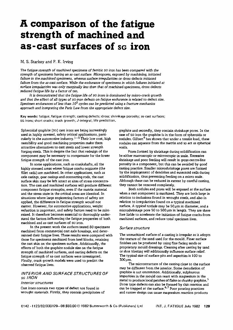
A comparison of the fatigue strength of machined and as-cast surfaces of sG iron M.S. Starkey and P. E. Irving
The fatigue strength of machined specimens of ferritic SG iron has been compared with the strength of specimens having an as-cast surface. Micropores, exposed by machining, initiated failure in the machined specimens, whereas surface irregularities or dross defects initiated failure from the as-cast surface. While the endurance of specimens in which failures initiated at surface irregularities was only marginally less than that of machined specimens, dross defects reduced fatigue life by a factor of ten.
It is demonstrated that the fatigue life of SG irons is dominated by micro-crack growth and that the effect of all types of SG-iron defects on fatigue endurance is related to defect size. Specimen endurances of less than 1 05 cycles can be predicted using a fracture mechanics approach and integrating the Paris Law from the appropriate defect size.
Key words: fatigue; fatigue strength; casting defects; dross; shrinkage porosity; as-cast surfaces; SG irons; short cracks; crack growth; J-integral; life prediction.
Spheroidal graphite {SG) cast irons are being increasingly used in highly stressed, safety critical applications, particularly in the automotive industry. 1- 3 Their low cost, high castability and good machining properties make them attractive alternatives to cast steels and lower strength forging steels. This is despite the fact that redesign of the component may be necessary to compensate for the lower fatigue strength of the cast iron.
In some applications, such as crankshafts, all the highly stressed areas where fatigue cracks originate (the fillet radii) are machined. In other applications, such as axle casings, gear casings and connecting rods, the cast surface skin may be left intact at sites of stress concentration. The cast and machined surfaces will produce different component fatigue strengths, even if the matrix material and the stress state in the critical areas are identical. In situations where large engineering factors of safety are applied, the difference in fatigue strength would not matter. However, for automotive applications, weight reduction is important, and safety factors need to be minimized. It therefore becomes essential to thoroughly understand the factors influencing the fatigue properties of both machined and as-cast surfaces of SG iron.
In the present work the authors tested 80 specimens machined from commercial cast axle housings, and determinted their fatigue lives. These results were compared with those for specimens machined from keel blocks, retaining the cast skin on the specimen surface. Additionally, the effects of both the graphite nodule size on the fatigue strength of machined surfaces, and casting defects on the fatigue strength of as-cast surfaces were investigated. Finally, crack growth models were used to predict the observed fatigue lives.
INTERIOR AND SURFACE STRUCTURES OF sa IRON Interior structures Cast irons contain two types of defect not found in wrought materials. Firstly, they contain precipitates of
graphite and secondly, they contain shrinkage pores. In the case of SG iron the graphite is in the form of spheroids or nodules. Gilbert4 has shown that under a tensile load, these nodules can separate from the matrix and so act as spherical voids.
Pores formed by shrinkage during solidification can be either macroscopic or microscopic in scale. Excessive shrinkage and poor feeding will result in gross centre-line porosity in a component, but this can be avoided by good casting practice. Smaller microshrinkage pores are formed by the impingement of dendrites and eutectoid cells during solidification, thus preventing feeding on a micro scale. Although these can be reduced in extent by careful casting, they cannot be removed completely.
Both nodules and pores will be exposed at the surface when a cast component is machined. They are both large in relation to inclusions found in wrought steels, and also in relation to irregularities found on a typical machined surface. A typical nodule may be 50pm in diameter, and a microshrinkage pore 50 to 500 pm in length. They are there fore liable to accelerate the initiation of fatigue cracks from machined surfaces, and reduce total specimen lives.
Surface structure
The unmachined surface of a casting is irregular as it adopts the texture of the sand used for the mould. Finer surface finishes c:an be produced by using fine facing sands or proprietary mould dressings. Cleaning after casting by sand or shot blasting will additionally influence surface relief. The typical size of surface pits and asperities is l 00 to 300pm.
The microstructure of the casting close to the surface may be different from the interior. Some denudation of graphite is not uncommon. Additionally, sulphurous impurities in the mould can react with magnesium in the metal to produce local patches of flake or chunky graphite. 5
Dross type defects can also be formed by this reaction and can be trapped at the surface.6•7 Poor pouring practices and runner design can cause magnesium reaction products
0142-1123/82/030129-08$03.00 © 1982 Butterworth & Co (Publishers) Ltd INT. J. FATIGUE July 1982 129
and slag to be swept into the casting where they tend to float to cope surfaces. 8 The fatigue properties of as-cast surfaces are therefore expected to be very different from those of machined surfaces.
DURABILITY OF MACHINED SURFACES
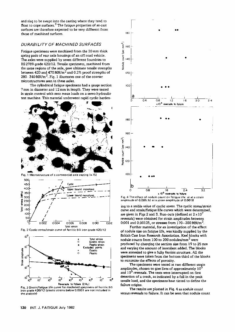
Fatigue specimens were machined from the 20 mm thick spring pads of rear axle housings of an off-road vehicle. The axles were supplied by seven different foundries to BS 2789 grade 420/12. Tensile specimens, machined from the same regions of the axle, gave ultimate tensile strengths between 420 and 470 MN/m2 and 0.2% proof strengths of 280-340 MN/m2. Fig. 1 illustrates one of the coarser microstructures seen in these axles.
The cylindrical fatigue specimens had a gauge section 7 mm in diameter and 12 mm in length. They were tested in strain control with zero mean loads on a servo-hydraulic test machine. This material underwent rapid cyclic harden-
L .. ··':~·~· ,. ~-·~~~ ~ ~- .·---
:£~-
•• :: "fl--. . - ~··· - . . . _,6.t,~
' I . l -~ (' ,
' \ / ,, I 'I
I
Fig. 1 Microstructure of a commercial axle casting (x 75)
~--------------~----------------
Cyclic
0004 0 006 0.008 0.010 0.012 Toto! str01n
Fig. 2 Cyclic stress/strain curve of ferritic SG iron grade 420/12
10°.----------------------------------------, x Total strain o Elastic strom tt Plastic strain
Excluded points + Elastic 0 Plastic
Reversals to failure (2 N 1 )
Fig. 3 Strain/fatigue life curve for machined specimens of ferritic SG iron grade 420/12 (plastic strains below 0.0001 are not included in the analysis)
130 INT. J. FATIGUE July 1982
~--·
I ;
• ••
"'
,0 r E
160 I E a; 3 c
140~ " 0 <.)
• • "' 3 '0 0 z
1201-
'ot •••
.L ... 0 0.4 08 1.2 16 20
x 10 3 rEM!fsols to f01lure
180 ••• •
160
.. -~ ! 140 • • • c 6 <.)
.J/ -g 120 z
100 • •••
lb 0 0.8 1.6 2.4 3.2
x 10!! reversals to failure Fig. 4 The effect of nodule count on fatigue life: a) at a strain amplitude of 0.005; b) at a strain amplitude of 0.0018
24
.,
ing to a stable value of cyclic stress. The cyclic stress/strain curve and strain/fatigue life curves which were determined, are given in Figs 2 and 3. Run-outs (defined at 2 x 10 7
reversals) were obtained for strain amplitudes between 0.001 and 0.00125, or stresses from 170-200 MN/m2.
Further material, for an investigation of the effect of nodule size on fatigue life, was kindly supplied by the British Cast Iron Research Association. Keel blocks with nodule counts from 100 to 200nodules/mm2 were produced by changing the section size from 19 to 25 mm and varying the amount of inoculant added. The blocks were annealed to give a fully ferritic structure. All the specimens were taken from the bottom third of the blocks to minimize the effects of porosity.
The specimens were tested at two different strain amplitudes, chosen to give lives of approximately 103
and 105 reversals. The tests were interrupted on first detection of a crack, as indicated by a fall in the peak tensile load, and the specimens heat tinted to define the failure origins.
The results are plotted in Fig. 4 as nodule count versus reversals to failure. It can be seen that nodule count
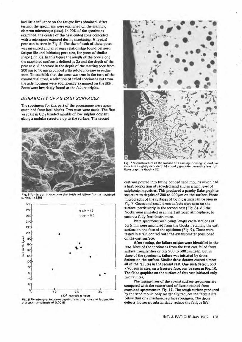
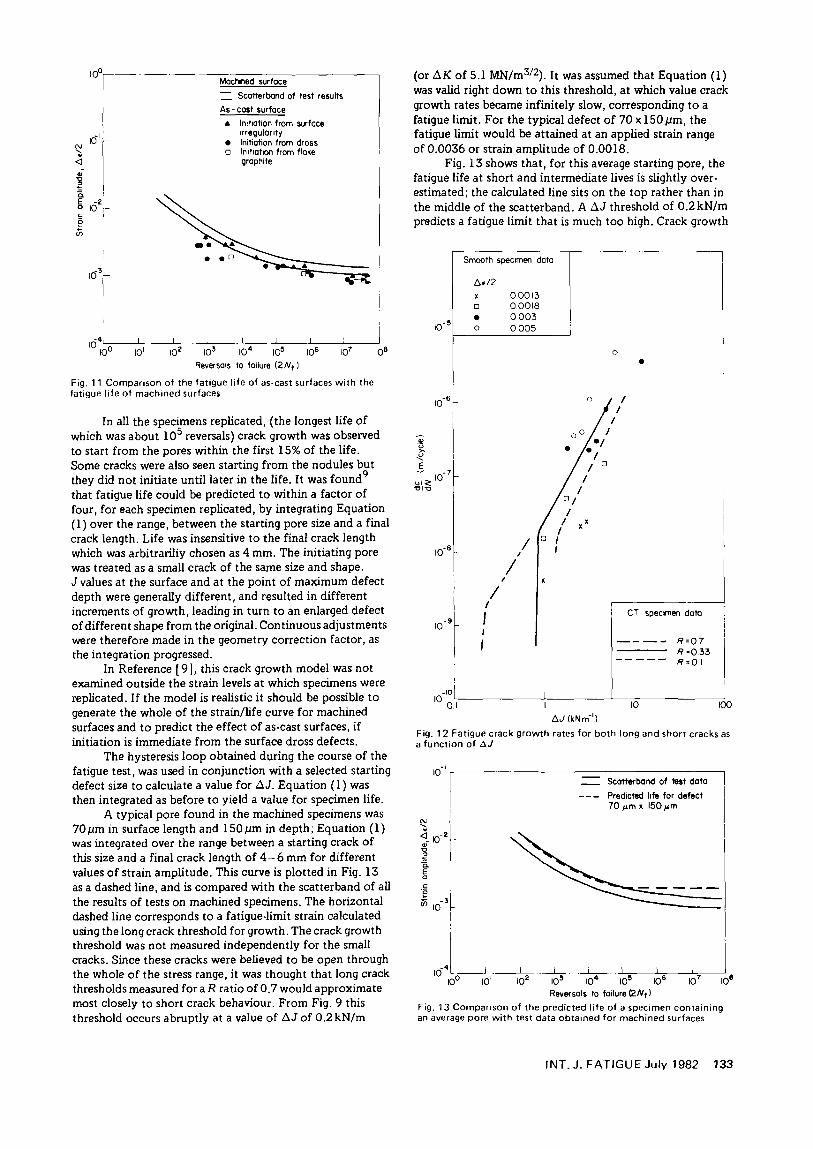
had little influence on the fatigue lives obtained. After testing, the specimens were examined on the scanning electron microscope (SEM}. In 90% of the specimens examined, the centre of the heat-tinted zone coincided with a micropore exposed during machining. A typical pore can be seen in Fig. 5. The size of each of these pores was measured and an inverse relationship found between fatigue life and initiating pore size, for pores of similar shape (Fig. 6 ). In this figure the length of the pore along the machined surface is defined as 2a and the depth of the pore as c. A decrease in the depth of the starting pore from 200 pm to 50 pm produced a threefold increase in endur· ance. To establish that the same was true in the tests of the commercial irons, a selection of failed specimens cut from the axle housings were additionally examined on the SEM. Pores were invariably found at the failure origins.
DURABILITY OF AS-CAST SURFACES
The specimens for this part of the programme were again machined from keel blocks. Two casts were made. The first was cast in C02 bonded moulds of low sulphur content giving a nodular structure up to the surface. The second
E ~~ :t. .
l :~±· ~ & 12
IOi. 80
6
4
2~L·--· · 0
•
•
X
• c/o> 15
~C!o=05
• •• •
•
---'------------L-·- ~ 10 20 30
x 10~ reversals to foiltn Fig. 6 Relationship between depth of starting pore and fatigue life at a strain amplitude of 0.0018
•. -,., .,. • •• • • • .. .. .... .
• • • •• ~ .. • r
I" • •
• -f •
' ... • .. • .... ..
•• • • • -· • · .
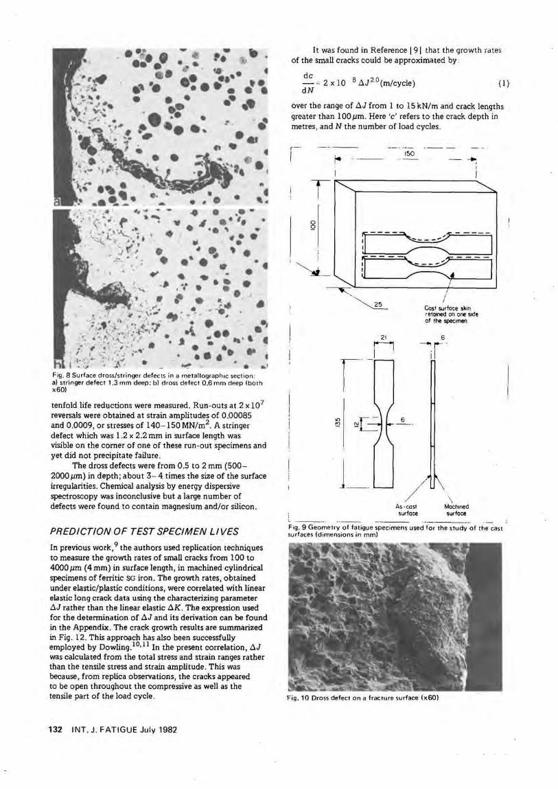
Fig. 7 Microstructure at the surface of a casting showing: a) nodular structure (sl ightly denuded) ; b) chunky graphite beneath a layer of flake graphi te (both x 751
cast was poured into furine bonded sand moulds which had a high proportion of recycled sand and so a high level of sulphonic impurities. This produced a patchy flake graphite structure to depths of 200 to 400 pm on the surface. Photo· micrographs of the surfaces of both castings can be seen in Fig. 7 . Occasional small dross defects were seen on the surface, particularly in the second cast (Fig. 8). AU the blocks were annealed in an inert nitrogen atmosphere, to ensure a fully ferritic structure.
Plate specimens with gauge length cross-sections of 6 x 6 mm were machined from the blocks, retaining the cast surface on one face of the specimen (Fig. 9). These were tested in strain control with the extensometer positioned on the cast surface.
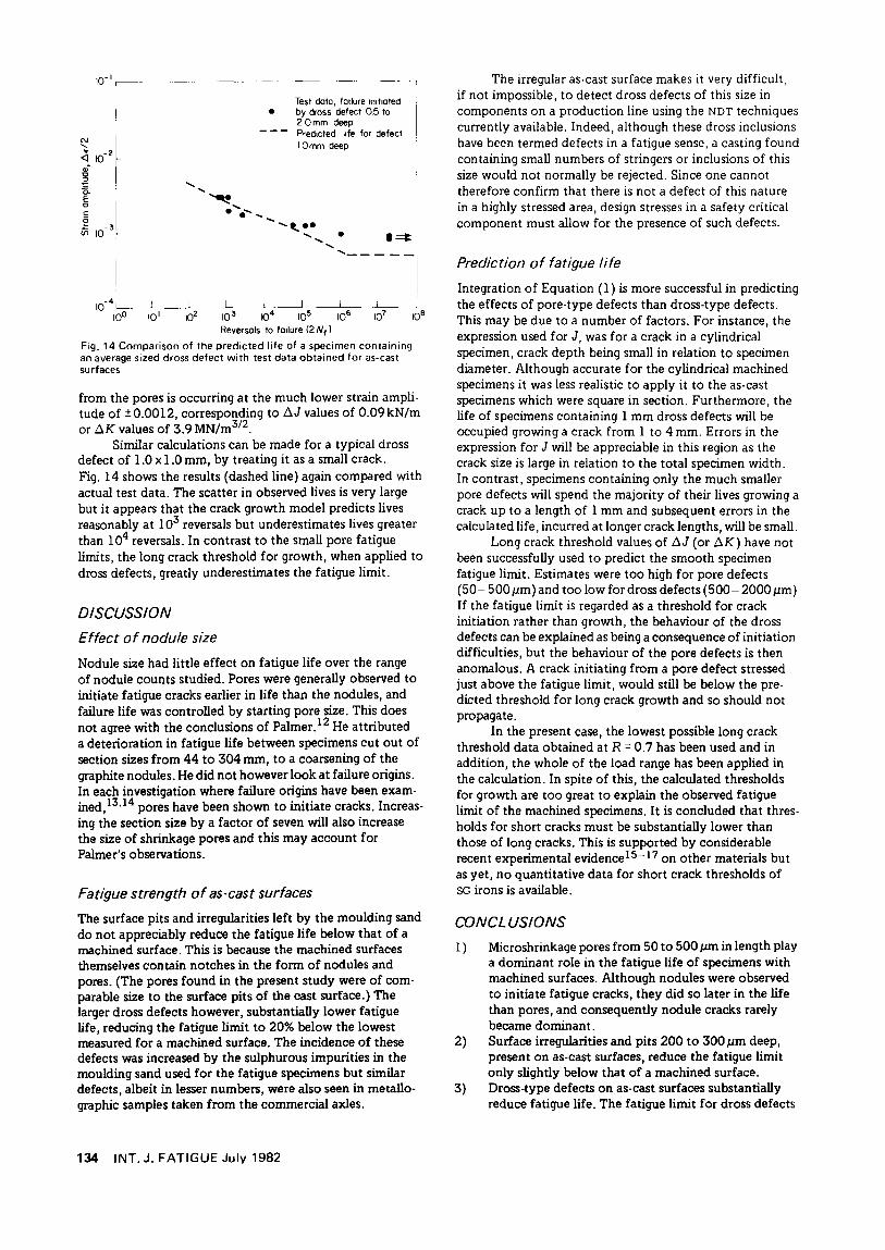
After testing, the failure origins were identified in the SEM. Most of the specimens from the first cast failed from surface irregularities or pits 200 to 300 pm deep, but in three of the specimens, failure was initiated by dross defects on the surface. Similar dross defects caused almost all of the failures in the second cast. One such defect, 350 x 700pm in size, on a fracture face, can be seen m Fig. 10. The flake graphite on the surface of this cast initiated only two failures.
The fatigue lives of the as-cast surface specimens are compared with the scatterband of lives obtained from machined specimens in Fig. 11. The rough surface produced by the sand mould only marginally reduces the fatigue life below that of a machined-surface specimen. The dross defects, however, substantially reduce the fatigue life;
INT. J. FATIGUE July 1982 131
.... - . . ····• .. ,. ~ . .. . • • •••• •' .• . ...... \
-· . . . . ... f ~- ~. •• •"" . . , ··e .• • . ~. . . ·.,, . .. ·
\ .. ·-... ... WI""'" ., . • • • ...
• I • • ., • • • '· .. . ,. -
1r .I •• '• . . .. " . ., . -:. • . ~' '. • •• • • ., •. . . ·• .~I ,.• a: e e , ~ . ~ ..
.'-# \.• ......... .. ~ .... ... • "' <llllrff ,. ~· .#
, ; ~'; ~~~\ ',::.t.: ~ . _1 • • ·~ \ .. : ,...-,; ':··:, ( ....... ~·· -·' . . • . ..... • .. • # • •• • , , ·. ",. . .. . .
I I .- • : .-." • • • • • .. • I•" • ,•• t ..f • ·~ ... . .._, . _., ...... . '
F ig. 8 Surface dross/stringer defects in a metallographoc section: a) stringer defect 1.3 mm deep; b) dross defect 0.6 mm deep (both x60)
tenfold life reductions were measured. Run-outs at 2 x 10 7
reversals were obtained at strain amplitudes of 0.00085 and 0.0009, or stresses of 140-150 MN/m2. A stringer defect which was 1.2 x 2.2 mm in surface length was visible on the corner of one of these run-out specimens and yet did not precipitate failure.
The dross defects were from 0.5 to 2 mm (500-2000 J.Llll) in depth; about 3- 4 times the size of the surface irregularities. Chemical analysis by energy dispersive spectroscopy was inconclusive but a large number of defects were found to contain magnesium and/or silicon.
PREDICTION OF TEST SPECIMEN LIVES
In previous work,9 the authors used replication techniques to measure the growth rates of small cracks from 100 to 4000 J.Llll (4 mm) in surface length, in machined cylindrical specimens of ferritic SG iron. The growth rates, obtained under elastic/plastic conditions, were correlated with linear elastic long crack data using the characterizing parameter D.J rather than the linear elastic D.K. The expression used for the determination of D.J and its derivation can be found in the Appendix. The crack growth results are summarized in Fig. 12. This approach has also been successfully employed by Dowling. 10• 11 In the present correlation, D.J was calculated from the total stress and strain ranges rather than the tensile stress and strain amplitude. This was because, from replica observations, the cracks appeared to be open throughout the compressive as well as the tensile part of the load cycle.
132 INT. J. FATIGUE July 1982
It was found in Reference 191 that the growth rates of the small cracks could be approximated by :
de - -'- 2 x 10 8 .1J20 (m/cycle) dN
(1)
over the range of D.J from 1 to 15 kN/m and crack lengths greater than 100 pm. Here 'c' refers to the crack depth in metres, and N the number of load cycles.
r - ·
I
T 0 Q
~--
~ ···-
1
l_ __
21
M i .
150
6
/ As-cost surface
.. ----· -----
J I
I Cos! surface skin retooned on one sode of the specimen
6 _., r- -i i
\ Machined surface
Fog. 9 Geometry of fatigue specimens used for the study of the cast surfaces (dimensions in mm)
Fig. 10 Dross defect on a fracture surface lx60)
N
' .;j .; ~ a. E 0
c: e (j,
a<-
-2 10 ;-
103:-
I
Mactwled surface = Scatterband of test results
As- cast surface
• lmflation from surface ~rregular~ty
• lnillat1on from dross CJ Initiation from flake
graphite
IO~'-o~-1-'---01 ~2 ·-~o-3- ~~-4- ~.I.Lo-=-s-~~__JIOe Reversals to failure ( 2 N 1 )
Fig. 11 Comparison of the fatigue life of as-cast surfaces with the fatigue life of machined surfaces
In all the specimens replicated, (the longest life of which was about 105 reversals) crack growth was observed to start from the pores within the first 15% of the life. Some cracks were also seen starting from the nodules but they did not initiate until later in the life. It was found 9
that fatigue life could be predicted to within a factor of four, for each specimen replicated, by integrating Equation (1) over the range, between the starting pore size and a final crack length. Life was insensitive to the final crack length which was arbitrariliy chosen as 4 mm. The initiating pore was treated as a small crack of the same size and shape. J values at the surface and at the point of maximum defect depth were generally different, and resulted in different increments of growth, leading in turn to an enlarged defect of different shape from the original. Continuous adjustments were therefore made in the geometry correction factor, as the integration progressed.
In Reference [ 9], this crack growth model was not examined outside the strain levels at which specimens were replicated. If the model is realistic it should be possible to generate the whole of the strain/life curve for machined surfaces and to predict the effect of as-cast surfaces, if initiation is immediate from the surface dross defects.
The hysteresis loop obtained during the course of the fatigue test, was used in conjunction with a selected starting defect size to calculate a value for f:l.J. Equation ( 1) was then integrated as before to yield a value for specimen life.
A typical pore found in the machined specimens was 70p.m in surface length and 150p.m in depth; Equation (1) was integrated over the range between a starting crack of this size and a final crack length of 4- 6 mm for different values of strain amplitude. This curve is plotted in Fig. 13 as a dashed line, and is compared with the scatterband of all the results of tests on machined specimens. The horizontal dashed line corresponds to a fatigue-limit strain calculated using the long crack threshold for growth. The crack growth threshold was not measured independently for the small cracks. Since these cracks were believed to be open through the whole of the stress range, it was thought that long crack thresholds measured for a R ratio of 0. 7 would approximate most closely to short crack behaviour. From Fig. 9 this threshold occurs abruptly at a value of f:l.J of 0.2 kN/m
(or f:l.K of 5.1 MN/m312). It was assumed that Equation (1) was valid right down to this threshold, at which value crack growth rates became infinitely slow, corresponding to a fatigue limit. For the typical defect of 70 x 150 p.m, the fatigue limit would be attained at an applied strain range of 0.0036 or strain amplitude of 0.0018.
Fig. 13 shows that, for this average starting pore, the fatigue life at short and intermediate lives is slightly overestimated; the calculated line sits on the top rather than in the middle of the scatterband. A /:l.J threshold of 0.2kN/m predicts a fatigue limit that is much too high. Crack growth
10-~
Smooth spec1men data
T 6·12 X
0
• 0
I I
I
00013 00018 0003 0.005
I
I
I •I
.I I ::J
I I
"I I
I x' I
o I I
0
I I
I
-,
•
CT specimen data
R=07 R=033 R=OI
-10 10 o'-~------..l~------'---:-IO:::-------c-:IOO
6J (kNm-1)
Fig. 12 Fatigue crack growth rates for both long and short cracks as a function of tJ..J
Scatterband of test data
Predicted hfe for defect 70 l<m x 150 l<m
Reversals to failure (2N,)
Fig. 13 Compar~son of the predicted life of a specimen containing an average pore with test data obtained for machined surfaces
INT. J. FATIGUE July 1982 133
..... ..... 'tilt!, ......... _
Test data, failure tmttated • by ci'os s defect 0 5 to
20mm deep Predtcted ltfe for defect IOmm deep
...... ~·· .......... . ·~ ..... ..... ____ _
10-4 L_ _ _____L___ _ __l__ L______,_ __ ____l__ _l___
10° 10 1 102 10 3 104 105 106 107 108
Reversals to f01lure (2 N1 )
Fig. 14 Comparison of the predicted life of a specimen containing an average sized dross defect with test data obtained for as-cast surfaces
from the pores is occurring at the much lower strain amplitude of ±0.0012, corresponding to AJ values of 0.09 kN/m or AK values of 3.9 MN/m312.
Similar calculations can be made for a typical dross defect of 1.0 x 1.0 mm, by treating it as a small crack. Fig. 14 shows the results (dashed line) again compared with actual test data. The scatter in observed lives is very large but it appears that the crack growth model predicts lives reasonably at I03 reversals but underestimates lives greater than I 04 reversals. In contrast to the small pore fatigue limits, the long crack threshold for growth, when applied to dross defects, greatly underestimates the fatigue limit.
DISCUSSION
Effect of nodule size
Nodule size had little effect on fatigue life over the range of nodule counts studied. Pores were generally observed to initiate fatigue cracks earlier in life than the nodules, and failure life was controlled by starting pore size. This does not agree with the conclusions of Palmer.12 He attributed a deterioration in fatigue life between specimens cut out of section sizes from 44 to 304 mm, to a coarsening of the graphite nodules. He did not however look at failure origins. In each investigation where failure origins have been examined, 13• 14 pores have been shown to initiate cracks. Increasing the section size by a factor of seven will also increase the size of shrinkage pores and this may account for Palmer's observations.
Fatigue strength of as-cast surfaces
The surface pits and irregularities left by the moulding sand do not appreciably reduce the fatigue life below that of a machined surface. This is because the machined surfaces themselves contain notches in the form of nodules and pores. (The pores found in the present study were of comparable size to the surface pits of the cast surface.) The larger dross defects however, substantially lower fatigue life, reducing the fatigue limit to 20% below the lowest measured for a machined surface. The incidence of these defects was increased by the sulphurous impurities in the moulding sand used for the fatigue specimens but similar defects, albeit in lesser numbers, were also seen in metallographic samples taken from the commercial axles.
134 INT. J. FATIGUE July 1982
The irregular as-cast surface makes it very difficult, if not impossible, to detect dross defects of this size in components on a production line using the NOT techniques currently available. Indeed, although these dross inclusions have been termed defects in a fatigue sense, a casting found containing small numbers of stringers or inclusions of this size would not normally be rejected. Since one cannot therefore confirm that there is not a defect of this nature in a highly stressed area, design stresses in a safety critical component must allow for the presence of such defects .
Prediction of fatigue life
Integration of Equation ( 1) is more successful in predicting the effects of pore-type defects than dross-type defects. This may be due to a number of factors. For instance, the expression used for J, was for a crack in a cylindrical specimen, crack depth being small in relation to specimen diameter. Although accurate for the cylindrical machined specimens it was less realistic to apply it to the as-cast specimens which were square in section. Furthermore, the life of specimens containing I mm dross defects will be occupied growing a crack from 1 to 4 mm. Errors in the expression for J will be appreciable in this region as the crack size is large in relation to the total specimen width. In contrast, specimens containing only the much smaller pore defects will spend the majority of their lives growing a crack up to a length of 1 mm and subsequent errors in the calculated life, incurred at longer crack lengths, will be small.
Long crack threshold values of AJ (or AK) have not been successfully used to predict the smooth specimen fatigue limit. Estimates were too high for pore defects (50- 500 ,urn) and too low for dross defects (500- 2000 ,urn) If the fatigue limit is regarded as a threshold for crack initiation rather than growth, the behaviour of the dross defects can be explained as being a consequence of initiation difficulties, but the behaviour of the pore defects is then anomalous. A crack initiating from a pore defect stressed just above the fatigue limit, would still be below the predicted threshold for long crack growth and so should not propagate.
In the present case, the lowest possible long crack threshold data obtained at R = 0.7 has been used and in addition, the whole of the load range has been applied in the calculation. In spite of this, the calculated thresholds for growth are too great to explain the observed fatigue limit of the machined specimens. It is concluded that thresholds for short cracks must be substantially lower than those of long cracks. This is supported by considerable recent experimental evidence 15- 17 on other materials but as yet, no quantitative data for short crack thresholds of SG irons is available.
CONCLUSIONS
1) Microshrinkage pores from 50 to 500 ,urn in length play a dominant role in the fatigue life of specimens with machined surfaces. Although nodules were observed to initiate fatigue cracks, they did so later in the life than pores, and consequently nodule cracks rarely became dominant.
2) Surface irregularities and pits 200 to 300 ,urn deep, present on as-cast surfaces, reduce the fatigue limit only slightly below that of a machined surface.
3) Dross-type defects on as-cast surfaces substantially reduce fatigue life. The fatigue limit for dross defects
0.5 to 2.0 mm deep was found to be 20% below the lowest measured on a machined surface. These defects are more severe in their effect on fatigue life than a 0.4 mm deep layer of surface flake graphite.
4) The growth rates of small cracks, larger than lOOpm, in these irons can be successfully correlated with long crack data, if it is assumed that the compressive as well as the tensile part of the load cycle is damaging.
5) For endurances less than 105 reversals, microcrack initiation from pores exposed by machining was observed to occur within the first 15% of life. The lives of these specimens could therefore be predicted by integrating crack growth data which had been characterized in terms of t.J.
6) At longer lives, it is possible that microcrack initiation forms a significant fraction of the total life, particularly for the more blunt dross defects.
7) The fatigue limit, measured on specimens containing dross defects, occurs at larger strains than that calculated from long crack threshold data.
8) The threshold for short crack growth was not measured directly. However, failures of machined specimens occurred from pore defects at t.J values smaller than the long crack threshold. This suggests that the threshold for the growth of short cracks of about l 00 pm, may be below the threshold for long crack growth.
ACKNOWLEDGEMENTS
The authors would like to thank BCIRA for providing some of the material used in this investigation and David Moore of Sheep bridge Engineering Ltd for developing methods to form surface flake graphite. Mr V. Kumar is thanked for his invaluable assistance with the experimental work. The advice and encouragement of many other colleagues at GKN Technology is also gratefully acknowledged, in particular that of Dr P. Watson, Head of Product Engineering, GKN Technology. The paper is published by permission of the late Dr T. L. Johnston, Director of GKN Technology Ltd.
APPENDIX
Using an estimation procedure, Shih & Hutchinson18 have derived an expression for the line integral J, for the case of a through crack in both small and large scale yielding. It was assumed that the material could be characterized by the Ramberg-Osgood relation. By stunming the small scale yielding and fully plastic solutions, the generalized expression for J is given by
J=1ra[0
; h(n)+2Ca:~) g(n)]
for a through crack of length 2a where: a is the applied stress; n is the strain hardening exponent; h(n) and g(n) are functions of n; E is Young's Modulus; and Ep is plastic strain.
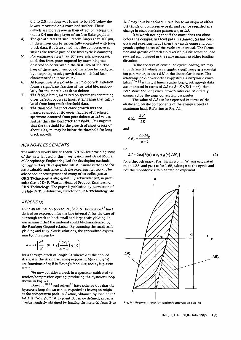
We now consider a crack in a specimen subjected to tension/compression cycling, producing the hysteresis loop shown in Fig. Al.
Dowling10• 11 and others19 have pointed out that the hysteresis loop shown can be regarded as having an origin at the compressive peak. A J value, obtained by loading the material from point A to point B, can be defined, as can a Jvalue similarly obtained by loading the material from B to
A. J may thus be defined in relation to an origin at either the tensile or compressive peak, and can be regarded as a change in characterizing parameter, or t.J.
It is worth noting that if the crack does not close before the compressive load peak is attained, (as has been observed experimentally) then the tensile going and compressive going halves of the cycle are identical. The formation and growth of crack tip reversed plastic zones on load reversal will proceed in the same manner in either loading direction.
In the context of continued cyclic loading, we may thus define t.J which has a similar significance as a correlating parameter, as does t.K in the linear elastic case. The advantage of t.J over other suggested elastic/plastic correlators20-22 is that, if linear elastic long crack growth data are expressed in terms of t.J via J = K 2/E ( l - v2), then both short and long crack growth rates can be directly compared by the same correlating parameter.
The value of t.J can be expressed in terms of the elastic and plastic components of the energy stored at maximum load. Referring to Fig. Al
t.a2 t.W: =-
e 2E
and
so
t.at.Ep t.W =--
P n + l
t.J = 21ra[h(n) 1:1We + g(n) /:1Wp] (2)
for a through crack. For this SG iron, h(n) was calculated to be 1.38, and g(n) to be 1.68, taking n as the cyclic and not the monotonic strain hardening exponent.
b 8
Fig. A 1 Hysteresis loop for tension/compression cycling
INT. J. FATIGUE July 1982 135
The cracks found in the smooth cylindrical specimens were semi-elliptical in shape. J at both the surface and tip of cracks of this geometry in an elastically loaded cylinder, were calculated using the Marc finite element package.23
The results were divided by the J expression for an elastically-loaded through crack, in order to obtain geometry correction factors,9 for the elliptical case.
It was assumed that these geometry correction factors, calculated for elastic loading, are also applicable to plastic loading and Equation (2) was modified by the constants derived from the Marc analysis. Hence flJ at the specimen surface;
and flJ at the crack tip
flJtip = f2{c/a} 2nc[ 1.38 AWe+ 1.68 AWp]
where f 1 {c/a) and f 2 (c/a) are two different functions of ratio of crack depth 'c' to half the crack surface length, 'a'.
REFERENCES
1. Watson, P. and Dabell, B. J. 'A realistic computer based comparison of SG iron and cast steel' in: Proc lnt Conf on The Applications of Computers in Fatigue, (SEE CO, Warwick, April 1978)
2. Mahnig, F., Trapp, H. G. and Walter, H. Konstruieren und Giessen No 1 ( 1977)
3. Mahnig, F., Trapp, H. G. and Walter, H. 'Fatigue strength and simulated service fatigue strength of automotive castings' Report from the Research and Development Department of Gsorg Fischer Ltd (Schaffhauser, Switzerland)
4. Gilbert, G. N.J. BCIRA Journal (March 1964) p 170
5. Murray, W. G. and Protheroe, H. T. The British Foundryman (June 1963) pp 294-307
6. Barton, R. BCIRA Journal (July 1967) pp 355-359
7. Askeland, D. R., Trojan, P. K. and Flinn, R. A.AFS Trans 80 (1972) pp 349-358
8. Barton, R. BCIRA Journal (September 1981) pp 340-352
136 INT. J. FATIGUE July 1982
9. Starkey, M.S. and Irving, P. E. 'Predict1on of fat1gue l1fe of small specimens of SG irons using a fracture mechanics approach' presented at: lnt Symp on Low Cycle Fatigue and Life Prediction, ( Firminy, France, 23/25 September 1980). To be published as an ASTM STP
10. Dowling, N. E. Cracks and Fracture, ASTM STP 601 ( 1976) pp 19-32
11. Dowling, N. E. Fatigue Crack Growth, ASTM 637 ( 1977) pp 97-121
12. Palmer, K. B. BCIRA Journal (November 1981) pp 385-391
13. Ostensson, B. JIron and Steel lnst (September 1973) PP 628-631
14. Testin, R. A. 'Characterization of the cyclic deformation and fracture behaviour of nodular iron' T & AM Report No 371 (University of Illinois, June 1973)
15. Elsender, A., Hopkins, P. and Batte, A. D. Metals Tech (June 1980) pp 256-258
16. Taylor, D. and Knott, J. F. Fatigue of Engng Mater and Structures 4 No 2 (1981) pp 147-155
17. Tanaka, K., Nakai, Y. and Yamashita, M. lnt J of Fracture 17 No 5 (October 1981) pp 519-533
18. Shih, C. F. and Hutchinson, J. W. 'Fully plastic solutions and large scale yielding estimates for plane stress crack problems' DEAP Report No S.14 (Harvard University, Cambridge, Massachusetts, USA, July 1975)
19. Turner, C. E. Private communication toP. E. Irving
20. Tomkins, B. Philosophical Magazine 18 (1968) pp 1041-1066
21. Skelton, R. P. Fatigue of Engng Mater and Structures 2 (1979) pp305-318
22. Solomon, H. D. J of Materials 7 ( 1972) pp 299-306
23. MARC-CDC Non Linear Finite Element Analysis Program, User Information Manual, Vols 1-111 (Publication Nos 17309500, 17311600, 17311700, Control Data Co, Minneapolis, USA)
AUTHORS
The authors are at GKN Technology Ltd's Group Technological Centre. Inquiries should be addressed to: Mrs M.S. Starkey, Group Technological Centre, GKN Technology Ltd, Birmingham New Road, Wolverhampton WV46BW, England.

DUCTILE IRON SOCIETY