cockroach-inspired winged robot reveals principles of...
TRANSCRIPT

Cockroach-inspired winged robot reveals principles of ground-baseddynamic self-righting
Chen Li1∗, Chad C. Kessens2, Austin Young3, Ronald S. Fearing3, and Robert J. Full3
Abstract— Animals and robots alike face challenges offlipping-over as they move in complex terrain. Small insects likecockroaches can rapidly right themselves when upside down,yet small fast-running legged robots are much less capable ofground-based self-righting. Inspired by the discoid cockroachthat opens its wings to push against the ground to self-right,we designed actuated wings for robot self-righting based onrecently-developed rounded shells for obstacle traversal [1]. Wemeasured the self-righting performance of a robot using theseactuated wings, and systematically studied the effects and trade-offs of wing opening magnitude, speed, symmetry, and winggeometry. Our study provided a proof-of-concept that robotscan take advantage of an existing body structure (roundedshell) in novel ways (as actuated wings) to serve new locomotorfunctions, analogous to biological exaptations [2]. Our resultsdemonstrated that the robot self-rights dynamically, with activewing pushing followed by passive falling, and benefits fromincreasing kinetic energy by pushing faster and longer. Our ex-periments also showed that opening both wings asymmetricallyincreases righting probability at low wing opening magnitudes.
I. INTRODUCTION
Robots are on the verge of venturing into the real-worldto aid humans in the performance of important tasks, suchas environmental monitoring, reconnaissance, search andrescue, and extra-terrestrial exploration. In doing so, theymust move through complex terrain such as desert, forestfloor, building rubble and debris, and the Martian surface.Because these surfaces are often uneven [3], sloped [4],dispersed [5], cluttered [1], or even flowable [6], robots canfrequently suffer static and dynamic instability, rotationalperturbations, loss of foothold, and inability to generateappropriate ground reaction forces, all of which pose risksfor flipping-over and losing mobility [7]. Therefore, groundself-righting capability is critical for effective locomotion andcontinual operation of robots.
Small, fast-running legged robots, such as RHex [3],iSprawl [8], and VelociRoACH [9], are particularly suscepti-ble to flipping-over, because they experience large dynamicinstabilities due to small body inertia [9] and terrain irregu-larities often comparable or even larger than themselves [10].
This work is supported by Burroughs Wellcome Fund Career Awardat the Scientific Interface (C.L.), Miller Institute for Basic Research inScience, University of California, Berkeley (C.L.), and United States ArmyResearch Laboratory under the Micro Autonomous Science and TechnologyCollaborative Contract (C.C.K., R.J.F).
1Chen Li is with Johns Hopkins University, Baltimore, MD 21218, USA2Chad C. Kessens is with the United States Army Research Laboratory,
Aberdeen Proving Ground, MD 21005, USA3Austin Young, Ronald S. Fearing, and Robert J. Full are with University
of California, Berkeley, CA 94720, USA*Author for correspondence: [email protected]
http://li.me.jhu.edu
These robots often have relatively short, springy legs withstiffness, power, and torque capabilities tuned to generate adynamically stable running motion [3], [8], [9], which areoften less useful for self-righting. As a result, these robotseither are not able to self-right, or must rely on energystorage and release mechanisms to perform aerobatics to self-right [11] [12].
To overcome the challenge of flipping-over, a variety ofground-based self-righting mechanisms have been developed,such as passively unstable body shape with low center ofmass [13] [14] [15], movable center of mass [14], recon-figurable wheels [16] and tracks [17], long manipulatorarms, levers, or legs [13], [18], [19], [20], spring-basedlegs [21], active tails [22], and self-reassembly [23], [24].However, few of these mechanisms have been implementedon small, fast-running legged robots, largely due to theirlimited payload. Some small legged robots work aroundthe problem of ground-based self-righting by adopting adorsoventrally symmetrical body design [11], [25] or onewith no “upright” orientation [26]. However, many tasks stillrequire a nominal upright orientation [11].
B
C
A
Fig. 1. Animals like insects are better than small fast-running legged robotsat overcoming the challenge of flipping-over during locomotion. (A) Thediscoid cockroach can almost always self-right quickly after flipping-overwhen traversing dense obstacles such as grass-like beams [1]. (B) It doesso by opening its wings to push against the ground [27]. (C) A robot witha cockroach-inspired rounded shell can traverse dense obstacles, but neverself-rights if flipped-over [1].
To self-right from an upside-down orientation, many ani-mals use exaptations [2] of appendages primarily used forother purposes [28], [29], [30], [31], [32]. For example, theflightless discoid cockroach have wings that are normallyclosed against the body to form a rounded shell to provideprotection and facilitate obstacle traversal [1] (Fig. 1A).
When flipped over, the cockroach can rapidly right itselfby opening its wings and pushing them against the ground(Fig. 1B) [27]. In a previous study, we enabled a small leggedrobot, VelociRoACH, to traverse dense obstacles such asgrass-like beams, by adding a cockroach-inspired roundedshell to facilitate body roll and reduce terrain resistance whenpushing through obstacle gaps [1] (Fig. 1C). However, therounded shell also rendered the robot trapped in a stableupside-down orientation if flipped over (Fig. 1C) [1].
We were inspired by the remarkable ability of insects touse the same body structure for multiple functions. In this pa-per, we further developed the rounded shell [1] into actuatedwings to serve the novel function of ground self-righting. Wedesigned a novel two degree-of-freedom joint and four-barlinkage transmissions to enable the wings to be opened in asimilar fashion as those of the cockroach. We calibrated themotor output to ensure that body weight and inertial forcedid not affect wing actuation during righting. We then testedwhether our cockroach-inspired actuated wings could enableself-righting, and systematically explored how wing openingmagnitude and speed affect righting performance. We applieda geometric modeling framework [18], [33] to assess whetherquasi-static righting is possible and examine the role of wingshape on kinematic and energetic requirement for dynamicself-righting, and used a simple dynamic model to understandthe passive falling dynamics during self-righting. Finally, wetested the robot with differential left and right wing actuationto understand the advantage of asymmetric wing opening forself-righting [27].
II. RIGHTING MECHANISM DEVELOPMENTA. Design of Actuated Wings
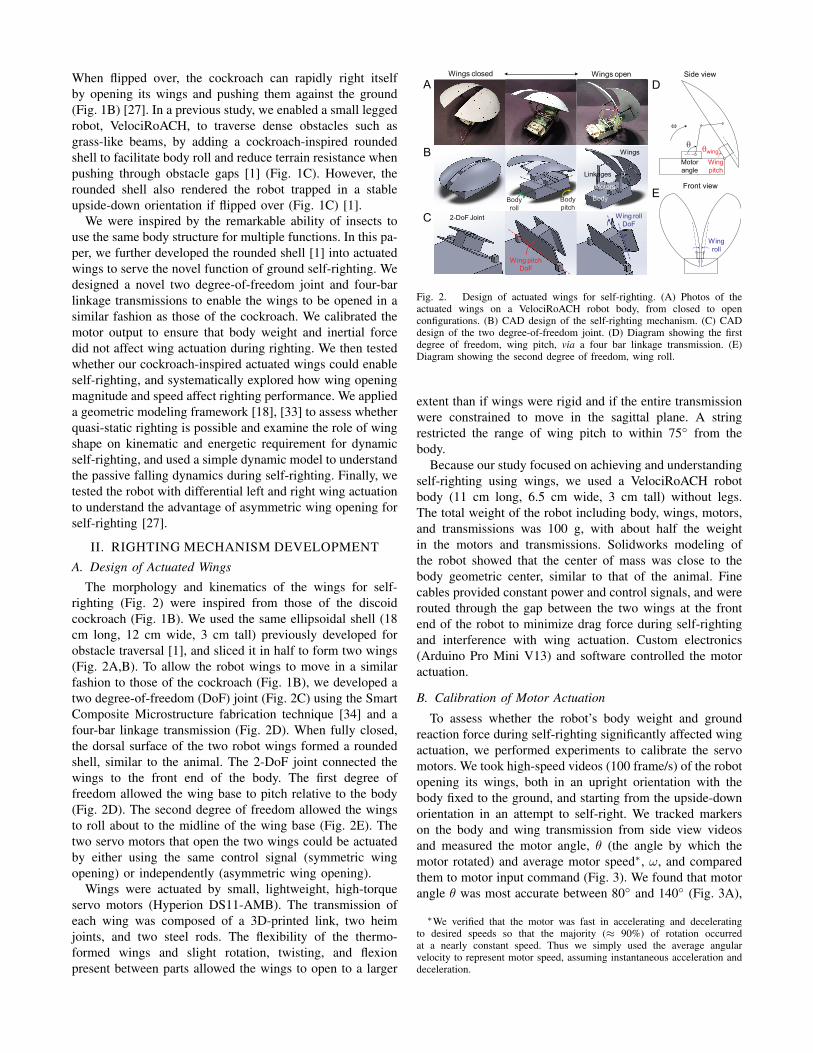
The morphology and kinematics of the wings for self-righting (Fig. 2) were inspired from those of the discoidcockroach (Fig. 1B). We used the same ellipsoidal shell (18cm long, 12 cm wide, 3 cm tall) previously developed forobstacle traversal [1], and sliced it in half to form two wings(Fig. 2A,B). To allow the robot wings to move in a similarfashion to those of the cockroach (Fig. 1B), we developed atwo degree-of-freedom (DoF) joint (Fig. 2C) using the SmartComposite Microstructure fabrication technique [34] and afour-bar linkage transmission (Fig. 2D). When fully closed,the dorsal surface of the two robot wings formed a roundedshell, similar to the animal. The 2-DoF joint connected thewings to the front end of the body. The first degree offreedom allowed the wing base to pitch relative to the body(Fig. 2D). The second degree of freedom allowed the wingsto roll about to the midline of the wing base (Fig. 2E). Thetwo servo motors that open the two wings could be actuatedby either using the same control signal (symmetric wingopening) or independently (asymmetric wing opening).
Wings were actuated by small, lightweight, high-torqueservo motors (Hyperion DS11-AMB). The transmission ofeach wing was composed of a 3D-printed link, two heimjoints, and two steel rods. The flexibility of the thermo-formed wings and slight rotation, twisting, and flexionpresent between parts allowed the wings to open to a larger
Motors
Body
Wings
Linkages
2-DoF Joint
Wings openWings closed
A
B
C
Wing pitch
DoF
Wing roll
DoF
D
E
Wing
roll
Motor
angle
Wing
pitch
Side view
Front view
θwingθ
ω
Body
roll
Body
pitch
Fig. 2. Design of actuated wings for self-righting. (A) Photos of theactuated wings on a VelociRoACH robot body, from closed to openconfigurations. (B) CAD design of the self-righting mechanism. (C) CADdesign of the two degree-of-freedom joint. (D) Diagram showing the firstdegree of freedom, wing pitch, via a four bar linkage transmission. (E)Diagram showing the second degree of freedom, wing roll.
extent than if wings were rigid and if the entire transmissionwere constrained to move in the sagittal plane. A stringrestricted the range of wing pitch to within 75◦ from thebody.
Because our study focused on achieving and understandingself-righting using wings, we used a VelociRoACH robotbody (11 cm long, 6.5 cm wide, 3 cm tall) without legs.The total weight of the robot including body, wings, motors,and transmissions was 100 g, with about half the weightin the motors and transmissions. Solidworks modeling ofthe robot showed that the center of mass was close to thebody geometric center, similar to that of the animal. Finecables provided constant power and control signals, and wererouted through the gap between the two wings at the frontend of the robot to minimize drag force during self-rightingand interference with wing actuation. Custom electronics(Arduino Pro Mini V13) and software controlled the motoractuation.
B. Calibration of Motor Actuation
To assess whether the robot’s body weight and groundreaction force during self-righting significantly affected wingactuation, we performed experiments to calibrate the servomotors. We took high-speed videos (100 frame/s) of the robotopening its wings, both in an upright orientation with thebody fixed to the ground, and starting from the upside-downorientation in an attempt to self-right. We tracked markerson the body and wing transmission from side view videosand measured the motor angle, θ (the angle by which themotor rotated) and average motor speed∗, ω, and comparedthem to motor input command (Fig. 3). We found that motorangle θ was most accurate between 80◦ and 140◦ (Fig. 3A),
∗We verified that the motor was fast in accelerating and deceleratingto desired speeds so that the majority (≈ 90%) of rotation occurredat a nearly constant speed. Thus we simply used the average angularvelocity to represent motor speed, assuming instantaneous acceleration anddeceleration.

and that motor speed ω was accurate up to 250◦/s (Fig. 3B).In addition, the added body weight and inertial force duringself-righting had little effect on motor actuation.
0 50 100 1500
50
100
150
0 100 2000
50
100
150
200
250
50 150 250
θ in (°)
θout (°)
ω in (°/s)
ωout (°/s)
upright uprightupside downupside downA B
Fig. 3. Comparison of (A) angle and (B) speed of motor output to motorinput. Black: upright; red: upside down. Diagonal lines indicate perfectmotor output.
III. SYMMETRIC RIGHTING EXPERIMENTSA. Righting via Symmetric Wing Opening
As a first step to test whether and how well the robot canself-right using wings, we chose to perform experiments ona flat, level, rigid surface. We positioned the robot upsidedown with the wings fully closed, and opened both wings insynchrony (symmetric wing opening) with the same motorangle θ and speed ω. We used high speed video to recordthe robot’s self-righting attempts from both top and side(Fig. 4A) views, and tracked markers on the robot body fromthe side view to measure the body pitch angle, θbody, andcalculated body angular velocity, ωbody .
Similar to the discoid cockroach, the robot body pitchedup as it opened both wings and pushed them against theground. As the body continued to pitch, it vaulted overthe front edge of the wings (analogous to the head of thecockroach) and successfully righted, with a change of bodypitch angle θbody from −80 ◦ to 90◦ (Fig. 4B, see attachedvideo). Because the robot did not close wings after wingopening, failed attempts resulted in the body settling into avertical orientation (θbody ≈ 0, see attached video).
0 0.5 1 1.5 2 2.5 3−90
−45
0
45
90
t (s)
θbody
(°)ω = 200°/s
ω = 250°/s
ω = 50°/s
ω = 100°/s
ω = 150°/s
A
B
Failure
Success
θbody
= −80° θbody
= 0° θbody
= 90°
Fig. 4. Body rotation of the robot during self-righting. (A) Snapshots ofthe robot during successful self-righting, with definition of body pitch angleθbody . (B) θbody as a function of time, t, for various motor speeds ω andangle θ. Trials of the same color use the same ω but different θ. Solid anddashed curves indicate successful and failed trials.
B. Effect of Wing Opening Magnitude & Speed
To discover principles of self-righting using symmetricwing opening, we tested how wing opening magnitude and
speed affected the robot’s performance (Fig. 5) includingrighting probability, Pright (success = 1, failure = 0), andrighting time, tright.
Although wing pitch angle θwing does not equal motorangle θ due to the four-bar linkage transmission (Fig. 2D),within the range of motor angle θ tested in righting experi-ments (≤ 140◦), θwing increases monotonically with θ (andthus ωwing increases monotonically with ω). Thus, we used θand ω as a proxy to test the effect of wing opening magnitudeand speed. Both θ and ω were varied within the range ofhigh motor fidelity: 80◦ ≤ θ ≤ 140◦ (which correspondedto 45◦ ≤ θwing ≤ 75◦), 0◦/s ≤ ω ≤ 250◦/s. Preliminaryexperiments showed excellent repeatability for all θ and ωtested (s.d. of tright < 0.1 s), thus we performed one high-speed video trial for each combination of θ and ω.
0 100 2000
0.5
1
1.5
2
0 100 2000
0.5
1
1.5
2
0 100 2000
0.5
1
1.5
2
t right (s)
ω (°/s)
t rise (s) t fall (s)
ω (°/s)
ω (°/s)
trise
∝ 1/ω
θ (°)
ω (°/s)
A
C
B
D
0
0.2
0.4
0.6
0.8
1right
Data
Model
max
100 150 200 250
100
120
140
8050
Success
Failure
P
θ = 80°
θ = 88°
θ = 92°
θ = 100°
θ = 102°
θ = 110°
θ = 120°
θ = 130°
θ = 140°
Fig. 5. Robot righting performance is sensitive to wing opening magnitudeand speed. (A) Righting probability (success = 1, failure = 0) as a functionof motor angle θ and speed ω. (B) Righting time, (C) rising time, and (D)falling time as a function of ω for a range of θ. In (B)-(D), redder colorsindicate higher θ and bluer colors indicate lower θ. In (D), dashed curvesare fits from the dynamic model (Fig. 8, Section IV B).
We found that increasing θ and increasing ω both in-creased the robot’s righting probability (Fig. 5A). When θwas sufficiently high (> 110◦), the robot always righted evenwith the lowest ω tested; when θ was sufficiently low (<88◦), the robot always failed to right even at the highestω tested. For intermediate θ (88◦ ≤ θ ≤ 110◦), the robotrighted at high ω but failed at low ω. Besides increasingrighting probability, increasing θ and ω also both maderighting faster. For any given θ, tright decreased with ω; forany given ω, tright also decreased with θ (Fig. 5B). Theseresults demonstrated that the more and faster the wings open,the more successful and quicker it is for the robot to self-right.
To better understand the righting process, we further exam-ined the time for the robot body to rise from the upside-downorientation to a vertical orientation, trise, and the subsequenttime for it to fall to the upright orientation, tfall. We foundthat trise was almost always inversely proportional to ω, anddiffered little when θ changed (Fig. 5C). By contrast, tfalldecreased with ω for any given θ, and decreased with θ forany given ω (Fig. 5D, circles).

IV. SYMMETRIC RIGHTING MODELING
A. Geometric Modeling
To understand whether the robot is capable of quasi-static self-righting or must right dynamically, we applieda generic planar self-righting analysis framework [18] andself-rightability metric [33]. Because the roll motion of thewings did not substantially change the projected wing shapein the sagittal plane (except for large motor angles), weapproximated the sagittal wing shape as a rigid truncatedellipse (Fig. 6A). To explore the effect of wing geometry,we constrained wing length L and truncation distance D andvaried wing height ϵL, where ϵ is wing height normalized towing length (for the robot used in experiments, L = 18 cmand D = 13 cm). Semi-major axis a was variable but deter-mined for any given ϵ. Body and wing dimensions, center ofmass positions, and body-wing joint position (Fig. 6B) weredetermined from the robot used in experiments.
A
2.7 cm
11 cm
18 cm
3 cm
0.2 cm
80 g
20 g
6 cm
0.6 cm
εL
BL
a
εL + D
D
Fig. 6. (A) Truncated elliptical model of the wings in the sagittal plane withgeometric variables (wing height ϵL, semi-major axis a) and constraints(wing length L and truncation distance D). (B) Planar geometric model ofthe robot.
Using the geometric framework [18], we examined howthe minimal wing pitch angle, θreqwing , required to guaranteeself-righting using quasi-static wing actuation (Fig. 7A)depended on wing height (see Fig. 7C for examples). Thiswould be necessary if, for example, a joint were highlygeared and unable to generate angular velocities that mightbe required for dynamic righting. We found that wing geom-etry had a significant impact on θreqwing . For less tall wings(ϵ ≤ 0.13), θreqwing was above 120◦ and changed little with ϵ.As wings became taller (ϵ > 0.13), θreqwing quickly decreasedwith ϵ. In particular, for the robot used in experiments withϵ = 0.17 (Fig. 7A, vertical line), the model predicted thatθreqwing ≈ 90◦. This means that kinetic energy would berequired if θwing could not reach 90◦. Because the robotused in experiments was only capable of θwing ≤ 75◦
(Fig. 7A, white region), it must be righting dynamically†.More broadly, the negative dependence of θreqwing on ϵ alsosuggests that, for quasi-static self-righting, an inability of therobot (or animal) to open wings to larger wing pitch anglescan be compensated by having taller wings, and having lesstall wings can be compensated by adopting a larger range ofwing pitch motion.
To understand the energetic requirements of dynamic self-righting, we constrained θwing to be ≤ 75◦ (based on
†We verified that the slight deformation of wing shape due to the rollmotion of the wings at large θ did not change this prediction.
the robot used in experiments) and calculated the minimalpotential energy barrier, ∆E, which the robot must overcometo self-right from the stable upside-down orientation withwings closed. We found that ∆E decreased with ϵ (Fig. 7B,solid curve), demonstrating that tall wings are energeticallymore advantageous by saving the mechanical energy neededfor dynamic righting. In addition, compared to one withactuated wings, a robot with static, closed wings (Fig. 7B,dashed curve) had to overcome a much higher ∆E, e.g., by ∼10× for the robot used in experiments with ϵ = 0.17 (verticalline). This suggests that animals save energy by using wingsto self-right compared to passive righting using rigid shells(e.g., turtles with highly-domed shells [30]).
∆E (mJ)
A B
θwing (°)req
Static wings
Actuated wings
ε ε
C
Robot
capability
range
0 0.1 0.2 0.3 0.40
30
60
90
120
150
0 0.1 0.2 0.3 0.40
20
40
60
80
ε = 0.35ε = 0.17ε = 0.08
Fig. 7. (A) Minimal wing pitch angle required for quasi-static self-rightingas a function of normalized wing height ϵ. (B) Minimal potential energybarrier that the robot must overcome to self-right from the stable upside-down orientation with wings closed. Solid: if the robot can actuate wings.Dashed: if wings are static relative to the body. (C) Schematics of the robotgeometric model with three representative wing heights. Vertical lines in(A) and (B) and the middle panel in (C) correspond with ϵ = 0.17, thevalue of the robot used in experiments.
These results also provide insights into the role of wingshape for biological self-righting using wings. The discoidcockroach has less tall wings (ϵ ≈ 0.08), which results inθreqwing > 90◦. While the animal is capable of opening wingsto achieve θwing ≈ 90◦, the θwing observed in our animalexperiments were mostly lower [27]. This suggests that theanimal also self-rights dynamically. In addition, the animal’sless tall wings are not the most beneficial if minimizingenergetic cost is the only goal. Other functions and con-straints may also play an important role in the evolution ofwing shape, such as protection and obstacle traversal [1].For robots to achieve multiple locomotor functions likeanimals (e.g., integrating actuated wings for self-rightingwith shells for obstacle traversal [1]), such trade-offs shouldbe considered.
B. Dynamic ModelingIn both our animal [27] and robot studies of self-righting
using wings, wings were held almost stationary relative tothe body until the animal or robot fully righted. Thus wehypothesized that body rotation dynamics during the fallingphase was governed by gravity.
To test this hypothesis, we developed a simple planardynamic model of a rigid body rotating under gravity about

a fixed pivot on the ground in the sagittal plane (Fig. 8A).This is a reasonable approximation of the robot because,for righting using symmetric wing opening, body rotationwas almost exclusively within the sagittal plane, and no slipand little rolling occurred at the ground contact point duringthe falling phase. We used Lagrangian method to derive theequation of motion:
dωbody
dt=
mgLsinθbodyIpitch +mL2
(1)
where θbody is body pitch angle, ωbody =dθbody
dt is bodypitch angular velocity, t is time, m = 0.1 kg is robot mass,L ≈ 0.08 cm is the distance between the center of massand the ground contact point, Ipitch ≈ 1.1 × 10⁻⁴ kg m2
is the moment of inertia of the robot along the pitch axisabout the center of mass‡, and g = 9.81 m/s2 is gravitationalacceleration.
t fall (s)
A B
ωbody
L
CoM
θbody = 0
θbody
mg 0 100 200
ωbody
(θbody
= 0) (°/s)
0
0.2
0.4
0.6
0.8
1
Fig. 8. Dynamic modeling of the falling phase during self-righting. (A)Schematic of a rigid body falling about a fixed pivot under gravity. (B)Model-predicted falling time as a function of body pitch angular velocitywhen the body was vertical.
Using this equation of motion, we numerically calculatedfalling time, tfall, for the rigid body to rotate from vertical(θbody = 0) to horizontal (θbody = 90◦) orientation, withthe body pitch angular velocity when the body was vertical,ωbody(θbody = 0), as the initial condition. Our modelpredicted a decreasing tfall as ωbody(θbody = 0) increased(Fig. 8B). This means that, the more kinetic energy the bodyhad accumulated before reaching the vertical orientation bypushing the wings against the ground (i.e., the faster it wasrotating), the more quickly it would impact the ground.
The dynamic model allowed us to understand our observa-tions of how wing opening magnitude θ and speed ω affectrighting. First, for any given θ, increasing ω resulted in anapproximately proportional increase in the body pitch angu-lar velocity when the body was vertical, i.e., ωbody(θbody =0) ∝ ω when θ is constant§. In other words, as ω increased,the robot moved in a kinematically similar fashion but athigher speeds (as reflected by the observation of trise ∝ 1/ω,
‡L and Ipitch were measured from the robot CAD model. L and Ipitch+mL2 changed little (up to ±15%) as the wings open.
§ωbody(θbody) ∝ ω is strictly true only before wing opening ceases.However, for the range of θ tested (80◦ ≤ θ ≤ 140◦), the θbody atwhich wing opening ceased ranged between −20◦ and 20◦, within whichωbody did not change substantially. Therefore, ωbody(θbody = 0) ∝ ωapproximately holds regardless of θ.
Fig. 5C). This means that faster wing opening reduced fallingtime by accelerating the body faster during the rising phaseand thus injecting more kinetic energy.
Second, for any given ω, an increase (or decrease) inθ increased (or decreased) the body pitch angle θbody atwhich the wings ceased pushing against the ground and thebody started falling under gravity. As a result, the kineticenergy of the robot when the body was vertical increased(or decreased). To compensate for this change, the robothad to push more slowly (or faster) for falling time toremain unchanged. This is equivalent to shifting the modelpredictions of tfall to the left (e.g., Fig. 5D, red curve) orright (e.g., Fig. 5D, green, cyan, blue, and dark blue curves).This means that larger wing opening magnitude reducedfalling time by accelerating the body over a larger angulardisplacement and thus injecting more kinetic energy.
We fitted our model to experimental observations of tfalland found excellent agreement (Fig. 5D). In addition, ourmodel predicted an upper bound for tfall of ≈ 1 s, whichmatched well with data, further supporting the plausibilityof the model.
Our dynamic model also provides insights into the dynam-ics and trade-offs of animal self-righting using wings. Weapplied the model to the discoid cockroach and found thatthe measured tfall were significantly shorter than predictedfor falling from a vertical orientation with no initial kineticenergy [27]. This suggests that the discoid cockroach buildsup substantial kinetic energy to overcome potential energybarriers and self-rights dynamically. In addition, our resultsthat decreasing wing opening magnitude can be compensatedby faster wing opening may have biological implicationsbecause muscle force depends strongly on contraction mag-nitude and velocity [35].
V. ASYMMETRIC RIGHTING EXPERIMENTSIn our study of the discoid cockroach self-righting using
wings [27], we observed that the animal often made multiplefailed attempts before it successfully righted. Although theanimal is capable of opening wings by wing pitch anglesas large as 90◦, they often opened wings by much smallermagnitudes even when successfully self-righting. Further, theanimal did not always open both wings symmetrically andpitch over the head in the sagittal plane, but often openedwings asymmetrically and rotated the body out of the sagittalplane to self-right (Fig. 9). We hypothesized that asymmetricwing opening may offer an advantage for self-righting.
Fig. 9. Self-righting of the discoid cockroach by asymmetric wing opening,resulting in asymmetric body rotation.
Our robot allowed us to test this hypothesis as we couldindependently control the actuation of the two wings. We

opened the left and right wings by different motor angles,θL and θR, and at different speeds, ωL and ωR, whilealways starting and stopping them in synchrony, i.e., θL/ωL
= θR/ωR, with no phase lag. We recorded high-speed videosof the robot self-righting, and tested how righting probabilityPright changed as wing opening asymmetry increased. BothθL and θR were varied between 50◦ and 140◦, with ωL/R
= 50◦/s when θL/R = 50◦. For each combination of θL andθR, 10 trials were performed.
We observed four outcomes when the robot attempted toright using asymmetric wing opening (Fig. 10A). First, whenθL and θR were both small, the robot often failed to right.Second, as θL or θR increased but were different, the robotoften under-righted (see attached video): the body rotatedenough to overcome the major potential energy barrier butdid not fully right due to minor potential energy barriersinduced by the corners and edges of the body. Third, when θLand θR were both large, the robot often succeeded in reachingthe upright orientation. Finally, for some combinations of θLand θR that were different, the robot overshot after reachingan upright body orientation, resulting in over-righting (seeattached video)¶. In our animal study, the discoid cockroachalso showed under-righting and over-righting, but couldalways fully right afterwards by using legs to adjust bodyorientation [27]. We noted that the reduced width between theground contact points of the two wings due to wing pitch andwing roll was essential to allow asymmetric body rotations.
Fail RightUnder-right Over-right
60 80 100 120 140
60
80
100
120
140
θR (°)
θL (°)
0
0.2
0.4
0.6
0.8
1
P
A
Bright
Fig. 10. Robot self-righting using asymmetric wing opening. (A) Snapshotsof four righting outcomes. See text for definition of righting probability ofeach outcome. (B) Average righting probability as a function of left andright wing opening magnitudes, θL and θR.
We calculated the average righting probability for eachcombination of θL and θR, by defining righting probabilityof failure, under-righting, over-righting, and success as 0,0.5, 0.5, and 1. When θL and θR were both large (> 100◦),righting probability Pright was high (> 80%) regardless ofwing opening asymmetry (Fig. 10B, top right). However,when θL and θR were both small (< 90◦), Pright was higher
¶We noted that trial-to-trial variations were higher for asymmetric wingopening than for symmetric wing opening.
for asymmetric wing opening (≈ 50%) than for symmetricwing opening (≈ 0) (Fig. 10B, bottom left).
These results elucidated the usefulness of asymmetricwing opening during self-righting. The animal’s wing open-ing magnitudes are highly variable from attempt to attempt,resulting in multiple failed attempts before successful right-ing is achieved. As the animal fatigues during failed rightingattempts, its wing opening magnitudes decrease. In thiscase, asymmetric wing opening becomes more advantageousbecause it increases the probability of righting and thusreduces the total number of attempts, time, and energyneeded. In addition, asymmetric wing opening results inasymmetric body rotations, which overcome lower potentialenergy barriers as compared to pitching over the head [27].Therefore, asymmetric wing opening may be an adaptationof the animal to right more quickly and economically.
VI. CONCLUSIONS & FUTURE WORK
We developed actuated wings to enable small leggedrobots to dynamically self-right. We demonstrated that robotscan use existing body structures in novel ways to achievenew locomotor capabilities, analogous to exaptations [2]or co-opting of structures common in animals. The robotfirst opened its wings to push against the ground, injectingkinetic energy to overcome potential energy barriers, andthen fell under gravity dynamically on its end to self-right.Our results showed that dynamic self-righting using wingsbenefits from larger amplitude and faster wing opening, andsuggested that the discoid cockroach uses substantial kineticenergy to dynamically self-right. When animals fatigue orrobots suffer power reduction or limitation, asymmetric wingopening becomes more useful because it increases rightingprobability and overcomes lower potential energy barriers.
Our next step is to integrate the self-righting mechanismwith rounded shells to enable legged robots to both traverseobstacles [2] and self-right. We envision that our approachwill help robots overcome diverse locomotor challengesand achieve life-like multi-modal locomotion in complexterrain without having to add complex, specialized struc-tures. Furthermore, we will continue to use our self-rightingrobot as a physical model to better understand dynamicself-righting [36]. For example, we plan to test if bodyvibrations help animals access lower energy barrier locomo-tor pathways [1], study how legs help correct under- andover-righting [27], and explore how the topology [20] andmechanical properties [1] of terrain affect self-righting. Wealso need to measure ground reaction forces and developmulti-body dynamic simulations [6] to better understand thedynamics of rising phase of righting.
ACKNOWLEDGMENT
We thank Rundong Tian, David Strachan-Olson, ZachHammond, Will Roderick, Mel Roderick, Sunny Aggarwalfor initial prototypes and preliminary experiments, KaushikJayaram, Nate Hunt, Tom Libby, Andrew Pullin for help-ful discussions, and four anonymous reviewers for helpfulcomments and suggestions.

REFERENCES
[1] C. Li, A. O. Pullin, D. W. Haldane, H. K. Lam, R. S. Fearing,and R. J. Full, “Terradynamically streamlined shapes in animalsand robots enhance traversability through densely cluttered terrain,”Bioinspiration & Biomimetics, vol. 10, no. 4, p. 046003, 2015.
[2] S. Jay, E. S. Vrba, S. Paleobiology, N. Winter, S. J. Gould, andE. S. Vrba, “Exaptation-A Missing Term in the Science of Form,”Palaeontology, vol. 8, no. 1, pp. 4–15, 1982.
[3] U. Saranli, M. Buehler, and D. E. Koditschek, “RHex: A Simpleand Highly Mobile Hexapod Robot,” The International Journal ofRobotics Research, vol. 20, no. 7, pp. 616–631, 2001.
[4] J. E. Bares and D. Wettergreen, “Dante II : Technical Description,Results, and Lessons Learned,” The International Journal of RoboticsResearch, vol. 18, no. 7, pp. 621–649, 1999.
[5] J. C. Spagna, D. I. Goldman, P.-C. Lin, D. E. Koditschek, andR. J. Full, “Distributed mechanical feedback in arthropods androbots simplifies control of rapid running on challenging terrain.”Bioinspiration & Biomimetics, vol. 2, no. 1, pp. 9–18, 2007.
[6] C. Li, T. Zhang, and D. I. Goldman, “A Terradynamics of LeggedLocomotion on Granular Media,” Science, vol. 339, no. 6126, pp.1408–1412, 2013.
[7] E. Guizzo and E. Ackerman, “The Hard Lessons of DARPA ’ sRobotics Challenge,” IEEE Spectrum, vol. 52, no. 8, pp. 11–13, 2015.
[8] S. Kim, J. E. Clark, and M. R. Cutkosky, “iSprawl: Design and tuningfor high-speed autonomous open-loop running,” The InternationalJournal of Robotics Research, vol. 25, no. 9, pp. 903–912, 2006.
[9] D. W. Haldane, K. C. Peterson, F. L. G. Bermudez, and R. S.Fearing, “Animal-inspired Design and Aerodynamic Stabilization ofa Hexapedal Millirobot,” IEEE International Conference on Roboticsand Automation, pp. 3279–3286, 2013.
[10] M. Kaspari and M. Weiser, “The size-grain hypothesis andinterspecific scaling in ants,” Functional Ecology, vol. 13, no. 4, pp.530–538, 1999.
[11] U. Saranli, A. Rizzi, and D. E. Koditschek, “Model-Based DynamicSelf-Righting Maneuvers for a Hexapedal Robot,” The InternationalJournal of Robotics Research, vol. 23, no. 9, pp. 903–918, 2004.
[12] A. M. Johnson and D. E. Koditschek, “Legged Self-Manipulation,” inIEEE Access, vol. 1, no. 33, 2013, pp. 310–334.
[13] P. Fiorini and J. Burdick, “The development of hopping capabilitiesfor small robots,” Autonomous Robots, vol. 2, no. 14, pp. 239–254,2003.
[14] M. Kovac, M. Schlegel, J.-C. Zufferey, and D. Floreano, “Steerableminiature jumping robot,” Autonomous Robots, vol. 28, no. 3, pp.295–306, dec 2009.
[15] E. Beyer and M. Costello, “Performance of a Hopping Rotochute,”International Journal of Micro Air Vehicles, vol. 1, no. 2, pp. 121–137, 2009.
[16] E. Tunstel, “Evolution of Autonomous Self-Righting Behaviorsfor Articulated Nanorovers,” Artificial Intelligence, Robotics andAutomation in Space, vol. 440, pp. 341–346, 1999.
[17] H. Schempf, E. Mutschler, C. Piepgras, J. Warwick, B. Chemel,S. Boehmke, W. Crowley, R. Fuchs, and J. Guyot, “Pandora: au-tonomous urban robotic reconnaissance system,” IEEE InternationalConference on Robotics and Automation, vol. 3, pp. 2315–2321, 1999.
[18] C. C. Kessens, D. C. Smith, and P. R. Osteen, “A Framework forAutonomous Self-Righting of a Generic Robot on Sloped Planar Sur-faces,” IEEE International Conference on Robotics and Automation,pp. 4724–4729, 2012.
[19] A. Kossett and N. Papanikolopoulos, “A robust miniature robot designfor land/air hybrid locomotion,” IEEE International Conference onRobotics and Automation, pp. 4595–4600, 2011.
[20] S. Peng, X. Ding, F. Yang, and K. Xu, “Motion planning andimplementation for the self-recovery of an overturned multi-leggedrobot,” Robotica, vol. 5, pp. 1–14, 2015.
[21] A. Klaptocz, L. Daler, A. Briod, J.-c. Zufferey, and D. Floreano, “AnActive Uprighting Mechanism for Flying Robots,” IEEE Transactionson Robotics, vol. 28, no. 5, pp. 1152–1157, 2012.
[22] G. Krummel, K. N. Kaipa, and S. K. Gupta, “A Horseshoe CrabInspired Surf Zone Robot with Righting Capabilities,” in ASME Inter-national Design Engineering Technical Conferences and Computersand Information in Engineering Conference, 2014, p. V05AT08A010.
[23] M. Yim, B. Shirmohammadi, J. Sastra, M. Park, M. Dugan, and C. J.Taylor, “Towards robotic self-reassembly after explosion,” IEEE/RSJInternational Conference on Intelligent Robots and Systems, pp. 2767–2772, 2007.
[24] G. Zong, Z. Deng, and W. Wang, “Realization of a modular recon-figurable robot for rough terrain,” IEEE International Conference onMechatronics and Automation, vol. 2006, pp. 289–294, 2006.
[25] P. Ben-Tzvi, A. a. Goldenberg, and J. W. Zu, “Design, simulations andoptimization of a tracked mobile robot manipulator with hybrid loco-motion and manipulation capabilities,” IEEE International Conferenceon Robotics and Automation, pp. 2307–2312, 2008.
[26] H. Tsukagoshi, M. Sasaki, A. Kitagawa, and T. Tanaka, “Design ofa higher jumping rescue robot with the optimized pneumatic drive,”in IEEE International Conference on Robotics and Automation, 2005,pp. 1276–1283.
[27] C. Li, T. Wohrl, H. K. Lam, and R. J. Full, “Fast, flipping cockroaches:dynamic, self-righting behavior,” in Integrative and Comparative Bi-ology, vol. 55, 2015, p. E111.
[28] R. Full, A. Yamauchi, and D. Jindrich, “Maximum single legforce production: cockroaches righting on photoelastic gelatin,” TheJournal of experimental biology, vol. 198, no. 12, pp. 2441–2452,1995.
[29] L. Frantsevich, “Righting kinematics in beetles (Insecta: Coleoptera).”Arthropod structure & development, vol. 33, no. 3, pp. 221–35, 2004.
[30] G. Domokos and P. L. Varkonyi, “Geometry and self-righting ofturtles.” Proceedings of The Royal Society of London B: BiologicalSciences, vol. 275, no. 1630, pp. 11–7, 2008.
[31] J. S. Young, L. S. Peck, and T. Matheson, “The effects of temperatureon walking and righting in temperate and Antarctic crustaceans,”Polar Biology, vol. 29, no. 11, pp. 978–987, 2006.
[32] J. Brackenbury, “A novel method of self-righting in the springtailSminthurus viridis ( Insecta : Collembola ),” Journal of Zoology, vol.222, pp. 117–119, 1990.
[33] C. C. Kessens, C. T. Lennon, and J. Collins, “A metricfor self-rightability and understanding its relationship to simplemorphologies,” IEEE/RSJ International Conference on IntelligentRobots and Systems, pp. 3699–3704, 2014.
[34] A. M. Hoover and R. S. Fearing, “Fast scale prototyping for foldedmillirobots,” IEEE International Conference on Robotics and Automa-tion, pp. 886–892, 2008.
[35] M. H. Dickinson, C. T. Farley, R. J. Full, M. A. R. Koehl, R. Kram,and S. Lehman, “How animals move: An integrative view,” Science,vol. 288, no. 5463, pp. 100–106, 2000.
[36] J. Aguilar, T. Zhang, F. Qian, M. Kingsbury, B. McInroe,N. Mazouchova, C. Li, R. Maladen, C. Gong, M. Travers, R. L.Hatton, H. Choset, P. B. Umbanhowar, and D. I. Goldman, “A reviewon locomotion robophysics: the study of movement at the intersectionof robotics, soft matter and dynamical systems,” Reports on Progressin Physics, 2016.