baffle and target/baffle carrier design - minos · 1 7/29/02 baffle and target/baffle carrier...
TRANSCRIPT

1
7/29/02
Baffle and target/baffle carrier design
Jim Hylen, Valeri Garkusha, Victor Zarucheisky, Ernie Villegas TABLE OF CONTENTS Carrier and Baffle Definition .............................................................................................. 3 Target/Baffle Carrier Functions and Requirements............................................................ 3 Baffle Functions and Requirements.................................................................................... 4 Target Motion Capability.................................................................................................... 5
Low Energy Target Insertion .......................................................................................... 5 Other Neutrino Energy Tunes......................................................................................... 5 Extended target motion by relocating target module...................................................... 6 Restriction of motion by carriage, hotcell....................................................................... 6
Target/baffle carrier hardware design................................................................................. 7 Carrier mechanical design............................................................................................... 7 Carrier thermal considerations........................................................................................ 8 Carrier Frame Stiffness ................................................................................................. 10 Flexible utility lines ...................................................................................................... 10 Target Module Endwall Penetrations............................................................................ 10
Baffle hardware design ..................................................................................................... 11 Baffle hole size, baffle location – beam accident geometry ........................................ 11 Baffle material .............................................................................................................. 13 Baffle outer radius......................................................................................................... 13 Baffle length.................................................................................................................. 13 Baffle atmosphere and windows................................................................................... 13 Baffle thermal warp ...................................................................................................... 14
Baffle cooling and monitoring.......................................................................................... 14 Accident scenario.......................................................................................................... 15 Continuous scraping...................................................................................................... 15 Calibration..................................................................................................................... 16 Commissioning alignment scan .................................................................................... 16
Effect of scraping on the neutrino spectrum..................................................................... 16 Figures............................................................................................................................... 18 References......................................................................................................................... 32

2
TABLE OF FIGURES Table 1 Length of target/baffle/carrier unit in various configurations. ............................. 7 Table 2 Approximate mass of carrier components, and loads. .......................................... 8 Table 3 Allocation of target module endwall utility penetrations. .................................. 11 Table 4 Target carrier electrical pin allocation. ............................................................... 11 Table 5 Maximum baffle hole radius allowed for different layouts of baffle, horn, and
target. ........................................................................................................................ 12 Table 6 Thermal parameters for two different air heat transfer coefficients.
Temperatures in parenthesis ignore radiative cooling, are prevented from occurring by a 120 deg C thermocouple limit input to beam interlock, but are included for illustration. ................................................................................................................ 15
Figure 1 Modules in target hall shielding. Target/baffle carrier mounted below target/baffle module, with target and baffle extended into the low energy position. Also visible are carriage cross beams, steel shielding, horn 1 mounted below horn 1 module....................................................................................................................... 18
Figure 2 Target/baffle carrier with target and baffle mounted. Target shown extended into the low energy neutrino beam position.............................................................. 19
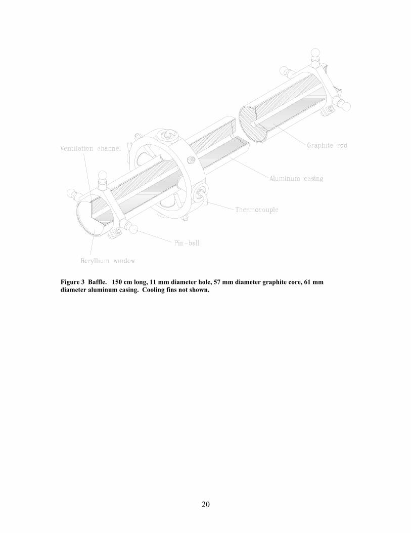
Figure 3 Baffle. 150 cm long, 11 mm diameter hole, 57 mm diameter graphite core, 61 mm diameter aluminum casing. Cooling fins not shown. ....................................... 20
Figure 4 (Rotated) target carrier side view. Target and baffle are shown in both Low Energy Beam extended position, and in fully retracted highest energy beam position.................................................................................................................................... 21
Figure 5 Target carrier end view...................................................................................... 22 Figure 6 Summary from study of beam energy deposition in carrier using MARS. ....... 23 Figure 7 Top view of Horn 1 module upstream endwall, which will be copied for the
target module. Utility penetrations include those labeled clamp, outer, inner, and the two large holes to the right of those labeled inner. ................................................... 24
Figure 8 Plan view of baffle, target, horn geometry. Since target is rectangular rather than cylindrical, limits of its horizontal and vertical extent are shown. Note large factor between horizontal and vertical scales. .......................................................... 25
Figure 9 Beam-eye view of baffle inner radius and comparison to beam spot, target fin, horn neck, and target cooling and support structure. ................................................ 26
Figure 10 Temperature rise of protected components for an accident spill as a function of the length of the baffle. The distance Lbt between the downstream end of the baffle and the target vertical fin is 176 cm (circles), 86 cm (boxes), and 41 cm (triangles).................................................................................................................................... 27
Figure 11 Temperature rise of protected components for an accident spill as a function of the position of a 1.5 m long baffle. Lbt is the distance from the end of the baffle to the start of the target vertical fin. The chosen design value of 68 cm is marked...... 28
Figure 12 Energy deposited in baffle (J/cm3/pulse) as a function of position along baffle for 4e13 protons hitting baffle. Integral is 42 kJ/pulse, corresponding to 22 kW at 1.87 second repetition rate, or 5.5% of the 400 kW total beam power..................... 29
Figure 13 Section of pin radiator. .................................................................................... 30

3
Figure 14 Effect of various amounts of beam-baffle scraping on neutrino spectrum. Top plots show spectra separately for 100% of beam on target or baffle. (Mark Messier, 6/12/02) ..................................................................................................................... 31
Carrier and Baffle Definition “Module” refers to the heavy shielding module that supports beam components below it, and has positioning motors mounted on top of it. The target/baffle carrier is a frame mounted on shafts through the target/baffle module. The module provides motion control of the target transverse to the beam by moving the shafts vertically and horizontally. The carrier supplies precision motion control of the target along the beam. When maintenance is required that cannot be done in situ, the entire module with carrier and components still mounted on it is moved to the hot work cell. The module, carrier, target and baffle are shown in Figure 1, Figure 2, and Figure 3. Please refer to the engineering drawing set for up-to-date definitive dimensions and layout. The integration drawing for the modules, carrier, and horn 1 is 8874.000-ME-363028. The final carrier and baffle drawings have not been made yet.
Target/Baffle Carrier Functions and Requirements Target/Baffle Carrier must:
• Remotely drive target into horn along beam axis after module is set in place: target casing extends 66.2 cm into horn, target module has 7.1 cm clearance to horn, thus minimum of 73.3 cm forward travel.
• Provide target motion capability to 250 cm retracted from the standard low energy
running position, to enable changing the energy tune of the neutrino beam.
• Set position of target and baffle to 0.5 mm transversely, and 1 mm longitudinally along beam line.
• Maintain position of target and baffle to 0.5 mm transversely and 1 mm
longitudinally under beam heating from 4x10¹³ protons / 1.87 sec striking target; this includes other beam energy tunes in addition to the standard low energy beam position.
• Provide the motion capability of the target and baffle utilities: target water supply
line, target water return line, target vacuum line, two Budal target monitor electrical lines, 8 thermocouple electrical lines.
• Maintain 1 inch clearance to target hall chase walls, in addition to the allowance
for +/- 8 mm horizontal and +8 mm / -9 inch vertical motion of support shafts.

4
• Provide a 2 cm radius “stay-clear” through the support structure that allows beam scans of downstream components when the target/baffle carrier is remotely lowered off beam axis (by ~ 9 inch).
• Survive radiation dose of up to 1011 rad/year for up to 10 years (except for the
drive shaft end which is above the module).
• Be short enough that it can be extracted through the target module carriage (199 inches) and inserted in the hot work cell (216 inches) with the target frozen in the extended position, or frozen with the baffle sticking out the back end in the target fully retracted position.
In addition, carrier will provide:
• Four tooling balls for survey, located at beamline elevation, one on each side of the beamline at each module endwall, visible through holes in the endwall.
• A pair of limit switches at each end of the travel of the target/baffle.
• Rotary encoder on drive shaft at the top of the module to give remote readback of
location of target along beamline.
• Include baffling to direct part of the chase air stream to the target that is otherwise blocked by the target base and support tube. Air flow must also be maintained over the length of the baffle and the target.
• Rust prevention coating of drive shaft and any other (non-stainless) steel parts.
Note secondary containment of radioactive water leaks is built into the target pile design, and is not a carrier design consideration.
Baffle Functions and Requirements The baffle must:
• Prevent mis-steered primary proton beam from causing damage to the horn neck and target cooling/support components.
• Be capable of operating continuously with 3% beam scraping at design
luminosity.
• Withstand full intensity of beam for a number of pulses it will take to detect mis-steering of beam and shut beam off.

5
• Incorporate monitoring that will shut beam off in case of continued large loss of beam on baffle. It may be useful for efficient running that loss of one pulse on baffle not turn off the beam.
• Construction and alignment tolerance of hole through baffle must be 0.5 mm or
better. In addition:
• Incorporate monitoring that allows detection and monitoring of beam-baffle scraping at order of 1% accuracy. (E.g. if 2% of the beam is being scraped, measure (2+/-1)%). Since actual full power beam running is expected be around 2x10¹³ during the first couple years running, this means an accuracy of +/-2x1011 or better.
• Incorporate monitoring that allows a cross-check of alignment via e.g. low
intensity beam-scan to 0.5 mm.
• Have the baffle move along the beamline with the target, as this increases the available target travel (the overall length for extraction of a broken target/baffle module is limited, and by having the target stick out one end of the carrier at one extreme of motion and the baffle stick out of the carrier at the other extreme one makes maximum usage of this length).
Target Motion Capability
Low Energy Target Insertion For the Low Energy Beam, the target will extend 66 cm into the horn with only 3 mm transverse clearance at the tip. The choice was made not to mount the target on the horn itself for fear of vibration damage to the target from horn pulsing. The target module will be set in place with the target in a retracted position. After the target module is surveyed into position, and the axis of the carrier aligned with the beamline (and horn) axis using the module motor drives, the target will be extended along the beam line into the horn using the carrier motor drive.
Other Neutrino Energy Tunes In NuMI-NOTE-BEAM-0783 [ref. i], the case was made that by extending the range of motion of the low energy target upstream one obtains the capability to quickly and easily change the energy of the neutrino beam. Such alternate energy tunes are labeled “semi-medium” and “semi-high” energy beams, and produce decent rates and spectra, although

6
not quite the performance that can be obtained with optimized targets and horn 2 positions for the alternate tunes. When moving the target, one is taking the chance that it could become stuck in some location. The target is in a high-radiation environment (e.g. humidity can turn to nitric acid), and repairs to the carrier mechanisms after being irradiated is mostly limited to replacement. Proper choice of materials can help mitigate this. However, this is a risk explicitly taken, and reinforces the need to have a complete spare target/baffle/carrier unit at beam-turn-on.
Extended target motion by relocating target module The target carrier allows for 2.5 m of target motion without moving the target module. The target can be moved even further upstream by moving the target module, although this is not a trivial exercise. The current baseline design allows space for one to move the target module 2 m upstream by unstacking some shielding, using the crane to move the 20 ton module, restacking shielding, and then doing a survey to check the final position. This would result in a total target range of 4.5 meters, but the last 0.5 m or so may be precluded by interference between the baffle and target hall upstream wall and beam pipe. (The standard high energy target position was 3.65 m upstream of the low energy position, and is reachable in this scheme.) The target/baffle carriage cross beams which limit the upstream movement of the module can be seen in Figure 1. Three pieces of steel shielding required for this new position are not in the baseline project, and would have to be acquired before the move.
Restriction of motion by carriage, hotcell Carrier frame Fixed frame 160 in. Moving components Total moving components 315.97 cm = 124.40 in. Baffle length 150 cm Baffle to vertical Target fin 68 cm Target fin length 95.38 cm Target casing beyond fin 2.59 cm Length normal extraction Components inside frame 160 in. Total length L.E. position Frame with target extended 188.86 in. Target extension 28.86 in. Frame length 160 in Total length fully retracted 2.5 m upstream of L.E. 193.97 in Baffle extension 33.97 in.

7
Frame length 160 inTable 1 Length of target/baffle/carrier unit in various configurations.
The opening in the target carriage shielding is 199.389 inches. The hot work cell is 216 inches long. These two openings set the maximum length of the target/baffle carrier and range of motion. The module with target/baffle possibly frozen in the fully extended or fully retracted position must be able to navigate through these openings, with operators controlling the crane by camera and remote control due to the high residual radiation. In the target extended downstream position, the length of carrier plus target is 189 inches. With 250 cm of motion capability, with the baffle extended out the upstream end, the baffle plus carrier is 194 inches long. See also Figure 4.
Target/baffle carrier hardware design
Carrier mechanical design The target and baffle frames have rollers which ride on aluminum rails, as shown in Figure 5. The rails are at beam height, and are supported by an aluminum tube space frame. Two hangers (sometimes miscalled clamps) connect the space frame to the shafts (not shown in the figure), which come through the module.
Components 215 lb Target Assy. 150 lb Baffle Assy. 65 lb Coils 47 lb One steel loop 0.581 lb Water in loop 0.194 lb 3x22 steel loops 38.3 lb 2x22 water loops 8.5 lb Carriage Assy. 598 lb Frame Assy. 231 lb Target baffle left support 120 lb Target baffle right support 110 lb Shaft support 44 lb Coil support 23 lb Drive system 70 lb Drive shaft loads 82 lb Components on 0.058 slope 12 lb Rolling friction (0.05 coef.) 11 lb Coil contraction, max. 30 lb Friction coil on supports (0.61 coef.) 29 lb

8
Table 2 Approximate mass of carrier components, and loads.
The aluminum rails are coated with tungsten-disulfide to provide a tough surface for the rollers to ride on. The rollers are commercially available cam-followers, black oxide coated steel in an aluminum housing. (These may be replaced with stainless steel if we can locate a vendor). They will be run dry, i.e. without grease. It is expected that the target location will only be changed a few hundred times, so the number of cycles is relatively small. The drive shaft is 1 inch diameter 17-4 PH heat treated stainless steel.
Carrier thermal considerations When running in the ME or HE locations, some of the target support shafts and rails will be downstream of the target, and thus receive substantial energy deposition from the secondary beam. MARS was used to calculate the energy depositions [ref. ii, see Figure 6 for summary of study]. In order to maintain thermal position stability, several measures are taken. Water cooling is supplied to the downstream module-to-carrier hanger (sometimes known as the clamp, in analogy to its use for horn 1), and the lower part of the support shaft is made of low-expansion steel. The water-cooled clamp design is copied from the horn 1 module design [ref. iii]. The bearing between this clamp and the carrier is on beam-centerline vertically. The clamp water cooling is not required for low energy beam running. Thus its water loop is separate on the module from the target water loop, so that failure in this system would not require replacing the target for low energy running. The carrier frame and rails are made of minimal volume to surface ratio aluminum and are kept at larger radius to the beam centerline. For initial design studies, a frame constructed of ¼ inch thick wall ¾ inch square aluminum tubing was assumed. The beam heating of the tubing plateaus about 1 m downstream of the start of the target (Figure 6). At a radius of 25 cm from the beam, the energy deposition in the aluminum is around 0.032 watts/gram. Assuming a heat transfer coefficient of 10 w/m2K to the 18 deg C air flowing in the chase, the asymptotic temperature calculated was 55 deg C, which is acceptable for the frame. The final design uses thinner 1/8 inch wall 2 inch square tubing, and thus should experience less than half the temperature rise. The beam heating upstream of the target is negligible. The drive shaft is placed at a radius of 40 cm from the beam-centerline. At that radius and downstream of the target, it is estimated that its temperature will be between 100degC and 150degC. The part that sets the target location is upstream of the target, and will remain cool. The downstream end of the shaft can be constrained transversely, but

9
allowance must be made for a 2 mm longitudinal expansion of the downstream part when running higher energy tunes.

10
Carrier Frame Stiffness Analysis of carrier support frame distortion has been carried out for three positions of the target; fully extended, fully retracted, and halfway in between. The vertical mis-alignment of points on the target and baffle due to changes in the loading of the carrier frame was at most about 0.2 mm. During the assembly of the target on the carrier frame, the target will be aligned such that the upstream and downstream ends of the target fin are vertically on axis; because of the sag of the target tube due to gravity, the middle of the target will be a fraction of a mm above the beam axis. The sag of the drive shaft is 5/16 inch when the target is in the fully extended position.
Flexible utility lines The 2.5 m travel of the target is accommodated by compressing a coil of 22 loops of pipe, 3/8” O.D. 0.028” wall stainless, total length 38 m per line. Three lines are used: water supply, water return, vacuum. In the LE position, the coil is unloaded. Fully retracted by the 2.5 m, the coil force is of order 30 lbs. The drive shaft is kept under tension, eliminating worry about buckling. (Putting the drive shaft in compression might have forced use of a larger diameter shaft, exacerbating cooling problems due to the larger volume to surface ratio). The maximum stress on the water line is calculated to be 20 ksi, which is below the yield stress of 35 ksi. Radiation hard thermocouple cable is produced commercially, consisting of a stainless steel sheath encapsulating a pair of wires in magnesium oxide insulation. We will use this cable for all electrical routing on the carrier. The flex necessary for the target motion will be obtained in similar fashion to that for the utility lines, i.e. a coil that expands or contracts, resting on an immobile support shaft. The voltage standoff required is reasonably modest. The target tube may see a voltage of order 50 Volts from the horn, since it follows the horn voltage closely due to beam ionization of the air between the horn and target tube. The Budal monitor may be run with a bias voltage of up to 75 volts, although a smaller bias (down to zero) can be used if necessary.
Target Module Endwall Penetrations The Horn 1 module upstream endwall has six penetrations for utilities, as shown in Figure 7. Target module upstream and downstream endwalls will copy this, with the assignments for usage shown in Table 3. Each electrical feed through contains five two-pin plugs. Connections are as show in Table 4, where the third baffle thermocouple could be re-allocated if some other electrical connection is required.

11
Upstream endwall 1 Upstream Left Survey Port 2 Upstream Right Survey Port 3 Drive Shaft for 2.5 m motion 4 Target water supply 5 Target water return 6 Target vacuum line
Downstream endwall 1 Downstream Left Survey Port 2 Downstream Right Survey Port 3 Clamp water supply 4 Clamp water return 5 Electrical feed through #1 6 Electrical feed through #2
Table 3 Allocation of target module endwall utility penetrations.
Plug Pin 1 Pin 2 1 Target Budal horizontal fin Shield for horizontal fin signal 2 Target Budal vertical fin Shield for vertical fin signal 3 Carrier thermocouple 1 Carrier thermocouple 1 4 Carrier thermocouple 2 Carrier thermocouple 2 5 Baffle thermocouple 1 Baffle thermocouple 1 6 Baffle thermocouple 2 Baffle thermocouple 2 7 Baffle thermocouple 3 (or spare) Baffle thermocouple 3 (or spare) 8 Wire from target vacuum jacket Ground for limit switches 9 U.S. limit switch 1 U.S. limit switch 2 10 D.S. limit switch 1 D.S. limit switch 2
Table 4 Target carrier electrical pin allocation.
Baffle hardware design The baffle is mounted with the target to eliminate the expense of another module to support and align it. The baffle and target can be pre-aligned to each other before attachment to the module, and move as a unit. The baffle construction tolerance is 0.2 mm RMS; the goal for overall baffle position accuracy is 0.5 mm, including thermal effects, survey tolerance, and carrier wobble.
Baffle hole size, baffle location – beam accident geometry

12
The baffle hole is made as large as possible while still providing protection to the horn and target. Figure 8 and Figure 9 show the layout of the baffle relative to the target and horn. The horn protection system actually consists of two baffle locations, a relatively large opening after the last bend string (but unfortunately before the last quad), and a second baffle in the target hall. Peter Lucas produced a spreadsheet which takes into account the magnetic field, and gives the maximum radius that the beam could reach while still passing through the two baffles. These limits are set entirely by the two baffles and the intervening magnet, and do not try to identify magnet failures that could actually produce these deviations. Examining some variations run by Adam Para, the pattern is roughly that the fully protected region is the baffle radius plus (0.5 mr horizontal, 0.7 mr vertical) times the distance downstream of the baffle. The following table lists three items to be protected by the baffle, and derives maximum baffle radii using the above rule of thumb for two cases: (1) having the baffle close to the target, and moving with the target, or (2) at a fixed upstream location which would still allow target movement to the HE location without moving the baffle. Baffle radius is reduced by 0.5 mm to allow for alignment tolerance. Numbers are in coordinate system where horn 1 starts at Z=0cm (i.e. the GNUMI Monte Carlo coordinate system). The horn neck is at (Z,R) = (0.8m,9mm); the top edge is shadowed by the target, so only the horizontal edge is included in the calculation. The target cooling line solder starts at (Z,R) = (-0.35m,7.5mm) at top and bottom of graphite fin; after some distance down target, the graphite contributes to shielding the tube. The cooling loop tube between supply and return is at the end of the target (Z,R) = (0.6m,7.7mm), and is exposed in the horizontal direction.
Baffle hole R(max) Baffle Z=-2m Baffle Z=-5m Horn 1 neck, X direction 7.1 mm 5.6 mm Target cooling tube, Y direction, LE position 5.8 mm 3.7 mm Target cooling loop, X direction, LE position 5.9 mm 4.4 mm Table 5 Maximum baffle hole radius allowed for different layouts of baffle, horn, and target.
From the above table, it is seen that a 5.5 mm radius baffle hole protects the horn for all baffle locations, for all different energy beams. If the target and baffle move together, then a 5.5 mm radius baffle will also protect the target for all beam configurations; however a fixed location baffle would require a smaller hole to protect the target. It is also seen that the X and Y requirements are very similar, and a circular hole thus makes sense. From the above arguments, the baffle is mounted near the target, moves with the target, and the radius of the hole is selected to be 5.5 mm. In the current layout, the baffle ends at -103 cm in the Monte Carlo coordinate system, or 68 cm before the leading edge of the target vertical fin.

13
Baffle material Calculations have been done of energy deposition, heat rise, and stress for the standard NuMI beam (4e13 protons in a 0.7 mm sigma-x 1.4 mm sigma-y beam spot) hitting Nickel, Copper, Aluminum, and Graphite. Nickel and Copper are clearly unsuitable. Aluminum is marginal; it would exceed its yield point and creep modestly with accident pulses [ref. iv]. Graphite is satisfactory [ref. v]. Beryllium would also work, but is rejected because it would generate mixed waste unnecessarily. We have selected Graphite; it is reasonable to use the same grade selected for the target, ZXF-5Q, since we already have experience with it in the target beam test.
Baffle outer radius IHEP has proposed shrink-wrapping the graphite in a long aluminum tube [ref. v]. This provides good thermal contact with the graphite that will be maintained under beam heating in spite of the larger thermal expansion coefficient of aluminum. Also it can be done with high accuracy. The technology they describe would limit baffle diameter to 60 mm; 60 mm would appear to be a reasonable match to NuMI requirements. The graphite diameter is 57.1 mm, which is a standard stock graphite rod size.
Baffle length Calculations have been done to find out how long the graphite baffle must be to protect the horn inner conductor, the target cooling tube and solder joint to the graphite, and the target ceramic. The position of the baffle was also varied. The position/length selected is that which has the upstream end of the baffle as close to the target as will still provide a good safety margin. This allows the greatest possible target motion. The result chosen is150 cm long baffle with 68 cm spacing between baffle and target fin. Curiously, extending the baffle length in the space between target and baffle further actually makes the energy deposition in the target fixturing worse, although it reduces the energy deposition in the horn neck. Please see [ref. v] for derivations of acceptable temperature rises; Figure 10 and Figure 11 include temperature rises for baffle lengths and positions calculated after [ref. v] was written.
Baffle atmosphere and windows [ref. v] documents that the maximum temperature in the core of an accident shower along the inner edge of the baffle is 344 deg C, at which temperature no detectable oxidation is expected. The oxidation threshold (temperature resulting in 1% weight loss in 24 hours) for ZXF-5Q is 450 deg C. Hence an inert atmosphere in the baffle is not required. Beryllium windows are provided to prevent erosion of the graphite by the strong wind in the target pile. A ventilation hole is provided to prevent air pressure buildup.

14
Baffle thermal warp A thermal gradient laterally across the baffle can be caused by azimuthally asymmetric beam loss, air flow, or cooling fin contact. This would cause the baffle to warp. The following arguments indicate such effects are not a problem for us. A zeroth order model with a linear temperature gradient across the cylinder gives a warp of the center relative to the ends of (αTL2/8w) where α is the coefficient of thermal expansion, T is the maximum temperature difference, L is the length of the baffle, and w is the width of the baffle. For a warp of 0.5 mm, this implies a temperature difference of 13.3 K for graphite across the baffle. Numerically modeling non-realistic extreme cases where the entire fin cooling was on one half of the baffle or the entire heat deposition was on one half of the baffle for 3% continuous scraping gave only a few degree temperature differences even at the higher temperature downstream end of the baffle. Hence this effect can be safely ignored.
Baffle cooling and monitoring Calorimetric methods are a simple and direct way of monitoring the beam loss on the baffle. For this to work, the cooling of the baffle should be adjusted so that temperature rises are easily measured with standard thermocouples but the baffle will not overheat. The simplest is to rely on heat transfer to the existing air flow, with the addition of fins to increase the heat transfer. However, heat transfer efficiency is hard to precisely calculate a priori, so a large safety factor should be built in for the operating parameters. Figure 12 shows the energy distribution when beam hits the front of the baffle [ref. vi]. This corresponds to an average temperature rise of 11 K per pulse at the downstream end of the baffle for full power beam. Since the largest temperature rise is downstream, the monitoring thermocouples should be mounted near the downstream end. To first order, the time constant for heat transfer to the cooling air is (Vdc/Ah), and the asymptotic temperature rise is (PV/Ah), where V is the volume of graphite, d is the density of graphite 1.8 g/cm3, c is the specific heat capacity of graphite 0.7 J/gK, A is the surface area of the graphite segment, h is the heat transfer coefficient from baffle to air, and P is the power deposited per unit volume. For a 3 cm radius cylinder, V/A = 1.5 cm. The cooling air flow along the surface of the baffle is about 4 m/s, which would give h~12W/m2K for flow parallel to a fin-less cylindrical baffle [ref. v]. The actual flow pattern is hard to predict, and with transverse flow the heat transfer coefficient could be double this. For use in selecting a strategy, a hypothetical fin with five times the heat transfer of the cylinder is chosen as a reasonable operating point, and shown in comparison in the table. The cooling air temperature will be about 16 deg C. Note that [ref. v] includes full three-dimensional modeling of the heat transfers, with results that agree well at the downstream end of the baffle with the simple approximation given here. The baffle fin design has not been finalized, but Figure 13 shows a concept. It consists

15
of two half rings 1.5 mm thick with pins 2 mm in diameter. Pins of 15 mm height are located with period 7 mm along the circumference and 9 mm along the baffle. The internal radius of a half ring is the same as the external radius of the baffle casing. These half rings are pressed to the baffle casing via a stainless steel clamp, providing pressure about 10-20 MPa. Such a pressure should provide a good thermal contact between radiator and casing. Another method of providing a good thermal contact is use of a 50 micron thick Indium film. The estimate of effective heat transfer coefficient of the pin radiator is 300 W/m2K at 4 m/s air velocity, which implies that only about 20% of the surface area of the baffle would have to be covered with the fins to achieve the desired heat transfer shown in Table 6. No fin, air flow parallel Fin on baffle Heat transfer coeff. (h) 12 W/m2K 60 W/m2K Time constant toward asymptotic temperature rise
1575 sec 315 sec
Asymptotic temperature rise, downstream end
Full power accident (9291 K) (1858 K) 3% continuous scraping (278 K) 56 K
1% desired monitoring accuracy 93 K 19 K Temperature rise per pulse, downstream end, full beam power
11 K
Table 6 Thermal parameters for two different air heat transfer coefficients. Temperatures in parenthesis ignore radiative cooling, are prevented from occurring by a 120 deg C thermocouple limit input to beam interlock, but are included for illustration.
Accident scenario To prevent damage to the aluminum baffle tube, an interlock will be set to prevent further beam pulses at a thermocouple readback of about 120 deg C. The interlock could be set lower if found to be operationally desirable. This would prevent more than at most a dozen continuous accident pulses; however the interlock will probably not be set tight enough to trip the beam from a single accident pulse. With the fin, the baffle will cool off in a few minutes, allowing one to turn the beam back on quickly.
Continuous scraping We are optimistic that beam scraping will be low. The fin design nevertheless would allow 3% continuous beam scraping with a safety factor of 2 in the heat transfer coefficient h before reaching the 120 deg C trip point.

16
The 19 K temperature rise per 1% beam loss is an order of magnitude larger than needed for monitoring the beam loss at the required level, providing a large safety factor on the value of h being larger than the design specification. Backgrounds to the calorimetric monitoring of the baffle scraping have also been calculated. The energy deposit in the baffle is 0.10 J/cm3/pulse for 1% scraping, compared to 0.04 J/cm3/pulse from interactions in the target pile air and 0.0002 J/cm3/pulse backscatter from the target [ref. vi]. Note that the thermal monitoring does not give pulse-by-pulse monitoring of the scraping, but an average with a few minute time constant. We have not yet found an argument showing a necessity for pulse-by-pulse monitoring of scraping.
Calibration The actual temperature response of the baffle will be calibrated during commissioning by steering 100% of the beam at low intensity on to the baffle. Note that a constant beam intensity should be maintained for a period of several time constants for this measurement.
Commissioning alignment scan The fin parameter set also allows an alignment check of the baffle via beam scan during commissioning, or whenever one wants to recheck alignment. It is conservative to turn down beam power during scans; beam intensity as low as 8x10¹¹ protons per pulse is easy to achieve. Such a single pulse (2% of maximum beam) into the baffle would produce only a 0.2 K temperature rise in the baffle, so one would need to use a large number of pulses per point (say 30 over a one minute period), or else a higher intensity beam (in which case one could limit the repetition rate) to produce a robust thermocouple response. With the standard 1 mm RMS beam spot, an alignment check accuracy of a fraction of 1 mm would be expected, based on experience with similar temperature scans done during the NuMI target test. Usable signals from the alignment check baffle scan will most likely also be detected in the horn 1 alignment ionization chamber and the hadron monitor in front of the absorber, providing redundancy. Since the baffle and target are pre-aligned on a common carrier, the combination of baffle scan and Budal-monitor target scan can demonstrate that the combined baffle/target system is at the correct angle as well as in the correct position.
Effect of scraping on the neutrino spectrum

17
The effect on the neutrino spectrum of beam tails hitting the baffle has been modeled in GNUMI, and is illustrated in Figure 14. The effect of scraping is mostly significant between 5 GeV and 8 GeV. In a 10 kty exposure, there will be of order 500 events in this range collected in the MINOS far detector, giving a statistical error of 4%. Thus knowing a scraping correction to 1% accuracy would keep the systematic error negligible compared to the statistical error. As shown in the figure, 1% beam scraping produces about a 1% change in the double ratio (beam scraping correction), hence measuring the scraping to +/- 1% of the total beam power is a reasonable specification. It would be nice to keep the scraping to less than 1%, so that no correction at all would need to be applied. For a gaussian beam with 1 mm RMS, 99% of the beam is within 3 mm radius. In our case, the baffle hole is 5.5 mm radius, and even after allowing for 0.5 mm alignment tolerances the loss from a gaussian beam would be negligible. However, only experience with the real beam will tell us if there are significant non-gaussian tails, or jitter in the beam position that cause losses on the baffle. Note this simulation had baffle to target distance of 37 cm instead of our current choice of 68 cm, but that should have only a minor effect. In a similar study with the baffle a couple meters further back, Brajesh Choudhary found the scraping sensitivity to be twice as large, which may be another motivation for keeping the baffle close to the target.

18
Figures
Figure 1 Modules in target hall shielding. Target/baffle carrier mounted below target/baffle module, with target and baffle extended into the low energy position. Also visible are carriage cross beams, steel shielding, horn 1 mounted below horn 1 module.

19
Figure 2 Target/baffle carrier with target and baffle mounted. Target shown extended into the low energy neutrino beam position.
20
Figure 3 Baffle. 150 cm long, 11 mm diameter hole, 57 mm diameter graphite core, 61 mm diameter aluminum casing. Cooling fins not shown.

21
Figure 4 (Rotated) target carrier side view. Target and baffle are shown in both Low Energy Beam extended position, and in fully retracted highest energy beam position.

22
Figure 5 Target carrier end view.

23
Figure 6 Summary from study of beam energy deposition in carrier using MARS.

24
Figure 7 Top view of Horn 1 module upstream endwall, which will be copied for the target module. Utility penetrations include those labeled clamp, outer, inner, and the two large holes to the right of those labeled inner.

25
9.0
7.5
5.5
680 mm
Horn/TargetProtectionBaf f le
Target
HornNeck
x 5
x 0.02Scale Factors
1.0
Target
TargetCan
Beamsigma
TargetCoolingTube
Targetvert .extent
Targethorz.extent
3.2
1500 mm
954 mm
2500 mm range ofmotion on carrier
Beam
Figure 8 Plan view of baffle, target, horn geometry. Since target is rectangular rather than cylindrical, limits of its horizontal and vertical extent are shown. Note large factor between horizontal and vertical scales.

26
Target Casing
Horn inner conductor
Target
TargetCooling
Baf f le6.4
11.0
18.0
30.0
21.4
15.0
Beam 1,2,3 sigma
Scale 4x, all units mm
Ø6.0
Target Dim 7/01 Dwg Set
beam rms 1 x 1 mm
0.4 mm wall
wa te rl inesupportr ing
wate rloop
8.08.0
motion capability +/- 8 mm
19.0
beryllium window support
Figure 9 Beam-eye view of baffle inner radius and comparison to beam spot, target fin, horn neck, and target cooling and support structure.

27
a) Cooling Pipe Steel
b) Horn Neck
c) Ceramic Insulator
d) Target Solder Joint
Figure 10 Temperature rise of protected components for an accident spill as a function of the length of the baffle. The distance Lbt between the downstream end of the baffle and the target vertical fin is 176 cm (circles), 86 cm (boxes), and 41 cm (triangles).

28
Cooling Pipe Steel
Horn Neck
Ceramic Insulator
Target Solder Joint
Figure 11 Temperature rise of protected components for an accident spill as a function of the position of a 1.5 m long baffle. Lbt is the distance from the end of the baffle to the start of the target vertical fin. The chosen design value of 68 cm is marked.

29
0
5
10
15
20
0 20 40 60 80 100 120 140
Baffle : Beam at r=15mm
dE
Ene
rgy
Dep
osite
d, J
/cm
3
Distance along beam direction
cm
Figure 12 Energy deposited in baffle (J/cm3/pulse) as a function of position along baffle for 4e13 protons hitting baffle. Integral is 42 kJ/pulse, corresponding to 22 kW at 1.87 second repetition rate, or 5.5% of the 400 kW total beam power.

30
Figure 13 Section of pin radiator.

31
baffle=(z=-221.593 cm,l=150 cm,φC=57.1 mm,φA=11 mm, 2 mm Al case)
0
5
10
15
20
25
30
35
0 5 10 15 20 25 30Eν (GeV)
ν µ C
C e
vent
s/kt
/3.8
E20
POT
/0.5
GeV
Far Det. Spectra
All protons on targetAll protons into baffle (r=6mm)
baffle=(z=-221.593 cm,l=150 cm,φC=57.1 mm,φA=11 mm, 2 mm Al case)
0
0.05
0.1
0.15
0.2
0.25
0.3
x 10-5
0 5 10 15 20 25 30Eν (GeV)
F/N
All protons on target
All protons into baffle (r=6mm)
baffle=(z=-221.593 cm,l=150 cm,φC=57.1 mm,φA=11 mm, 2 mm Al case)
0.92
0.94
0.96
0.98
1
1.02
1.04
1.06
1.08
0 5 10 15 20 25 30Eν (GeV)
(F/N
)/(F
/N 0
% s
crap
e)
5 % scrape
4 %
3 %
2 %
1 %
Figure 14 Effect of various amounts of beam-baffle scraping on neutrino spectrum. Top plots show spectra separately for 100% of beam on target or baffle. (Mark Messier, 6/12/02)

32
References i Proposal for Continuously-Variable Beam Energy, M. Kostin, S. Kopp, M. Messier, D. Harris, J. Hylen, A. Para, NuMI-NOTE-BEAM-0783, 10/17/01. ii Energy deposition in target support structure, R. Rameika, B. Lundberg, 3/02. iii Thermal Analysis of Clamp Using MARS Analysis Heat Generations, Bob Wands, 9/12/01. iv Thermal Stress Analysis of Numi Baffle – II, MSG-EAR-0282, Bob Wands, 4/2/01 and Thermal Stress Analysis of Numj Baffle, MSG-EAR-00279, Bob Wands, 11/8/00. v Technical Design of the Target Pile Protection Baffle-draft, S.Filippov, V. Garkusha, R. Gibadullin, F. Novoskoltsev, I. Ponimash, T. Ryabova, V. Zarucheisky, (IHEP) 4/30/02. vi MARS Simulation: Baffle Heating, B. Lundberg, 6/9/02.