aircraft conceptual design using vehicle sketch pad
TRANSCRIPT
Aircraft Conceptual Design Using Vehicle Sketch PadWilliam J. Fredericks, 1 Kevin R. Antcliff,2 Guillermo Costa , 3 Nachiket Deshpande,4
Mark D. Moore,5 Edric A. San Miguel,6 Alison N. Snyder7
NASA Langley Research Center, Hampton, VA, 23681
Vehicle Sketch Pad (VSP) is a parametric geometry modeling tool that is intended for usein the conceptual design of aircraft. The intent of this software is to rapidly model aircraftconfigurations without expending the expertise and time that is typically required formodeling with traditional Computer Aided Design (CAD) packages. VSP accomplishes thisby using parametrically defined components, such as a wing that is defined by span, area,sweep, taper ratio, thickness to cord, and so on. During this phase of frequent design builds,changes to the model can be rapidly visualized along with the internal volumetric layout.Using this geometry-based approach, parameters such as wetted areas and cord lengths canbe easily extracted for rapid external performance analyses, such as a parasite drag buildup.At the completion of the conceptual design phase, VSP can export its geometry to higherfidelity tools. This geometry tool was developed by NASA and is freely available to U.S.companies and universities. It has become integral to conceptual design in the AeronauticsSystems Analysis Branch (ASAB) here at NASA Langley Research Center and is currentlybeing used at over 100 universities, aerospace companies, and other government agencies.This paper focuses on the use of VSP in recent NASA conceptual design studies to facilitategeometry-centered design methodology. Such a process is shown to promote greater levels ofcreativity, more rapid assessment of critical design issues, and improved ability to quicklyinteract with higher order analyses. A number of VSP vehicle model examples are comparedto CAD-based conceptual design, from a designer perspective; comparisons are also made ofthe time and expertise required to build the geometry representations as well.
Nomenclature
Cd = Local drag coefficientCDo = Parasitic drag coefficientCf = Skin friction coefficientCf-L = Laminar skin friction coefficientCf-T = Turbulent skin friction coefficientCf-A = Weighted average skin friction coefficientCL = Lift coefficientCl = Local lift coefficientCP = Pressure coefficient
I. Introduction
THIS paper addresses a number of topics to the capabilities and uses for Vehicle Sketch Pad (VSP). To this point,the need to make frequent design iterations during the conceptual design phase has prevented significant use of
geometry modeling early in the design process. VSP has the capability to rapidly model aircraft, thus making ageometry-centered conceptual design process possible. Its parametric-based modeling makes this software easy tolearn. Examples are given of studies that have used this capability to allow this geometry-centered design process.
1 Aerospace Engineer, Aeronautics Systems Analysis Branch, 1 North Dryden St. Mail Stop 442, Young Professional2 Summer Student, Aeronautics Systems Analysis Branch, 1 North Dryden St. Mail Stop 442, Student3 Summer Student, Aeronautics Systems Analysis Branch, 1 North Dryden St. Mail Stop 442, Student4 Summer Student, Aeronautics Systems Analysis Branch, 1 North Dryden St. Mail Stop 442, Student5 Design Engineer, Aeronautics Systems Analysis Branch, 1 North Dryden St. Mail Stop 442, Senior Member6 Summer Student, Aeronautics Systems Analysis Branch, 1 North Dryden St. Mail Stop 442, Student7 Summer Student, Aeronautics Systems Analysis Branch, 1 North Dryden St. Mail Stop 442, Student
American Institute of Aeronautics and Astronautics
II. Why Use Vehicle Sketch Pad?
Computer Aided Design (CAD) programs have been used for many years to develop accurate representations ofobjects for analysis and manufacturing. These programs work quite efficiently and accurately for many kinds of oddobjects across a wide variety of functions and industries. However, in creating an aircraft, the shortcomings of thesesoftware programs make the process rather difficult and time consuming, which precludes their use duringconceptual design. VSP was created to address the specific needs of aircraft conceptual design.
A. Modeling Time with VSP as Compared to CAD SoftwareThe main difference between CAD software and VSP is ease of use. Users who possess even a passing
familiarity with aircraft components and terminology can learn 75 percent of the features of VSP without formalinstruction by simply using the program. The remainder of the features can be understood by reading the manual,which may take an hour at most. The learning curve for VSP is negligible relative to CAD. This ease of use ispossible because VSP parametrically defines each part. For example, a wing may be defined by its area, taper ratio,and aspect ratio. If one of these values is changed, the part simply adjusts without requiring any redrawing on thepart of the user.
CAD programs are highly complex and require what can at times be a difficult learning curve. Creating a modelin these legacy programs is a complicated process that involves multiple steps per part. This is due to the fact thatlegacy programs are not designed for any specific type of design; while this may impart some measure of flexibilityto said programs, it also forces users who must operate within a specific design field (i.e., aircraft) to learn featuresand abilities for which they will have no use. This is further seen in the training regimen for these programs, inwhich portions of the software are compartmentalized into separate training modules, some of which require weeks(or months) of constant learning on the part of the user.1. Functionality
The user’s initial reaction to VSP is the amount of freedom that the program permits. Most of the commonfunctions (e.g., slide, move, zoom) are accomplished with the mouse or a small number of hot keys. Moreimportantly, the components that are included with the program can be modified in ways limited only by the user’simagination.
VSP contains 11 basic parts to model an aircraft. These 11 parts can be modified to create any possible variationof that part, including the creation of components that are not readily listed. For instance, although turning pipesand landing gear are not listed in the Parts window, both can be created simply by altering aspects of theMultisection Wing (MS_Wing) and Fuselage parts.
CAD software does not have the same degree of functionality. Without the aforementioned instruction,maneuvering through this software is challenging. As a user attempts to create a simple model without instruction,many errors are encountered; error codes are frequently not helpful in fixing the problem. This is in part due to thecomplexity of the program; VSP is generally intuitive.2. Examples
To illustrate VSP’s unique characteristics, a test model of a hypothetical air vehicle is created in both VSP andAutodesk InventorTM 2009 (reference 2). Inventor was chosen as a representative CAD software package becauseone of the authors was already familiar with the program. We discuss 4 of the 11 basic parts, plus a pipe that wasbuilt in VSP.
1) WingsVSP
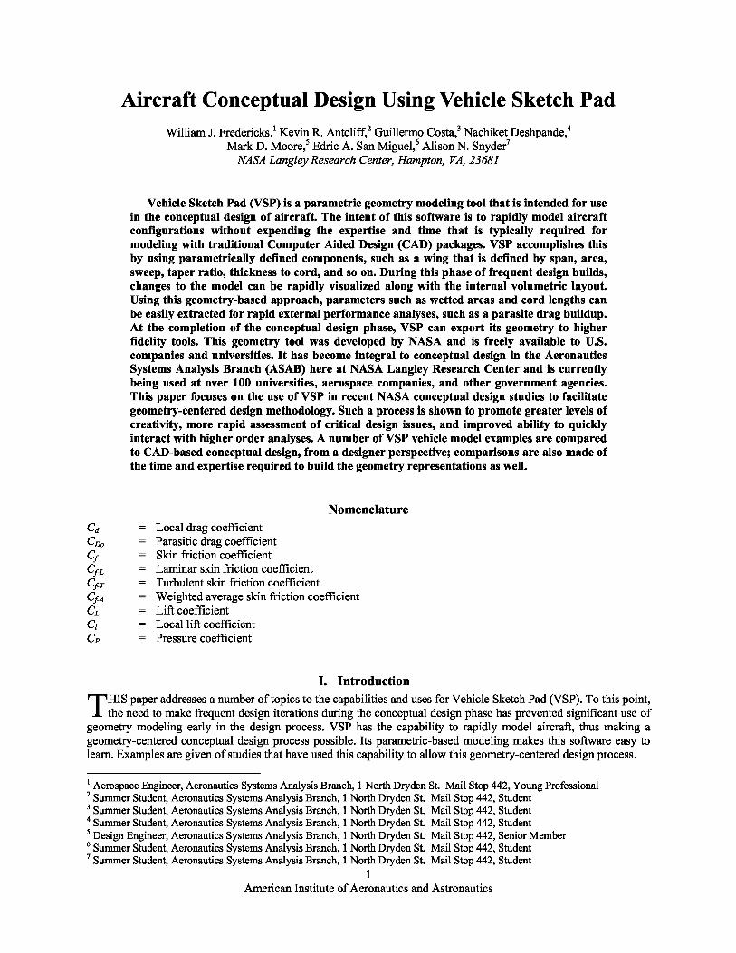
Two wings options are available in VSP: the MS_Wing and the Hybrid Wing Body (HWB). Theseare modeled in different ways. For a simple rectangular wing, the Multi-Section Wing is the best choice;delete all but the innermost section and reset the sweep to zero. The resulting wing is shown in Figure 1.
To create a Multi-Section Wing, one can add as many sections as needed, each with its ownindependent sweep, offset, chords, and dihedral angles. These parameters can be changed quickly in theparameters window for the part, giving the user a great deal of flexibility in the type of wing they candesign. Even highly unconventional wing planforms can be created with ease and simplicity, as shownin Figure 2.
American Institute of Aeronautics and Astronautics
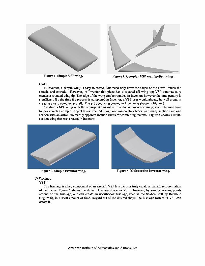
Figure 1. Simple VSP wing. Figure 2. Complex VSP multisection wings.
Figure 3. Simple Inventor wing. Figure 4. Multisection Inventor wing.
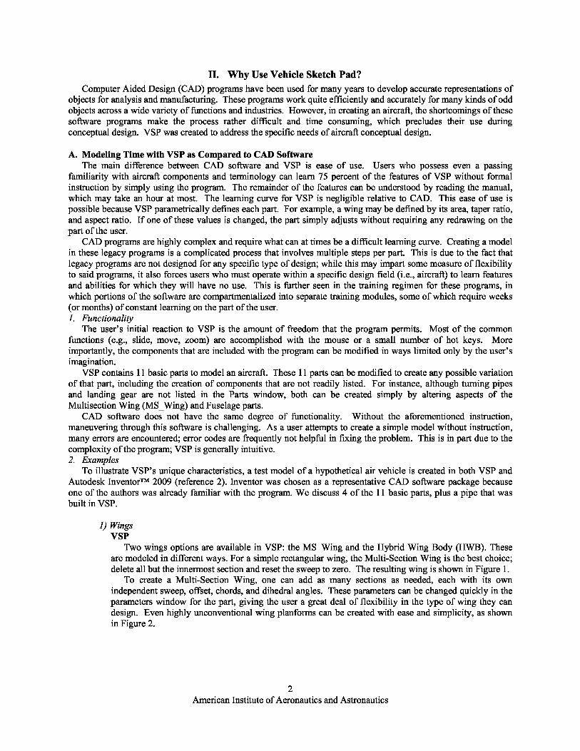
CADIn Inventor, a simple wing is easy to create. One need only draw the shape of the airfoil, finish the
sketch, and extrude. However, in Inventor this piece has a squared-off wing tip; VSP automaticallycreates a rounded wing tip. The edge of the wing can be rounded in Inventor; however the time penalty issignificant. By the time the process is completed in Inventor, a VSP user would already be well along increating a very complex aircraft. The extruded wing created in Inventor is shown in Figure 3.
Creating a MS_Wing with the appropriate airfoil in Inventor is time-consuming; even planning howto tackle such a complex object takes time. Although one can create a block with many sections and onesection with an airfoil, no readily apparent method exists for combining the two. Figure 4 shows a multi-section wing that was created in Inventor.
2) FuselageVSP
The fuselage is a key component of an aircraft. VSP lets the user truly create a realistic representationof their idea. Figure 5 shows the default fuselage shape in VSP. However, by simply moving pointsaround on the fuselage, one can create an unorthodox fuselage, such as the Seabee built by Republic(Figure 6), in a short amount of time. Regardless of the desired shape, the fuselage feature in VSP cancreate it.
American Institute of Aeronautics and Astronautics

Figure 5. Default VSP fuselage. Figure 6. Republic Seabee fuselage in VSP.
CADA fuselage is much more difficult to create in Inventor. Figure 7 shows a slender cylinder attached to
both a sphere and a semicone, created to represent a fuselage shape similar to the default VSP fuselage.Theoretically, one could model any shape to the rear of the cylinder to create the tail cone; however, theprocedure is complex, and the end result is unrealistic to accomplish in the conceptual design phase.
Figure 7. Inventor fuselage.3) Jet Engine
VSPJet engines represent an important and difficult portion of design. An engine must appear realistic for
the design to be of value; however, often a design requires multiple engines, which must be spacedevenly along a predetermined axis. Figure 8 shows two default VSP engines. By selecting one of foursymmetry options (i.e., XZ, XY, YZ, None), the user is able to duplicate the engines and separate eachone some distance away from the aircraft’s centerline. Only a minimal amount of effort is required (inthis instance, specifying the distance at which each engine is to be offset from the center). The user isrelieved from further tedious actions.
VSP permits great detail in the creation of the engines. Every aspect of the engine is parameterized,for example: length, diameter, hub diameter, inlet and exhaust nozzle area ratio, external mold line shapefactors, and many more. The user can even model the inlet duct like the center engine on the Boeing 727.If the user is unable to create the desired engine shape, a fuselage or a duct can easily be adapted to lookquite similar to an engine.
VSP also has a propeller component that is very flexible. The default propeller settings resemble thepropeller on a typical general aviation airplane; a helicopter rotor can easily be modeled too.
Figure 8. Default VSP jet engine.
American Institute of Aeronautics and Astronautics

CADThe jet engine shown in Figure 9 was created in Inventor. As was the case with the fuselage, the end
result is quite blocky and not very aerodynamic. Extensive work with chamfering and filleting wouldstill need to be done before this engine could be seriously considered for an aircraft design. Furthermore,unlike VSP, Inventor does not have a symmetry feature built in; as such, creating multiple engines for theaircraft requires an extensive amount of measuring and re-measuring to ensure that the location of eachengine is symmetrical to the aircraft centerline.
Figure 9. Inventor jet engine.
4) Turning PipeVSP
Turning pipes can serve a number of functions; for instance, they can be used inside the vehicle toshow the routing of exhaust ducts for powered lift aircraft, the location of control sticks, and so on. Thisis arguably the only component that can be modeled more easily in Inventor than in VSP, because theturning pipe in VSP must be created by modifying a multisection wing with a circular airfoil. However,the pipe’s diameter, length, and angle can be readily modified in either program. Figure 10 shows a 90deg turning pipe created in VSP.
Figure 10. VSP 90-deg pipe.
CADFigure 11 shows the same turning pipe created in Inventor. As previously mentioned, this part was
easier to model in Inventor than in VSP. However, if a pipe component were created in VSPindependently of the aircraft, it could be added to a parts list and then inserted and modified as needed infuture designs. This step is possible in Inventor, although the user is forced to search a complex andextended list of items in order to manipulate the pipe.
Figure 11. Inventor 90-deg pipe.
American Institute of Aeronautics and Astronautics

Figure 12. Boeing 787 in Autodesk Inventor Figure 13. Boeing 787 in VSP
3. Comparison of VSP to CADSome of the aforementioned components were combined to create an aircraft in both programs. The results are
shown below. Figure 13 shows a Boeing 787 model created in VSP. This model took 1 hr, 23 min to create.Creation of a Boeing 787 was attempted in Inventor within the same timeframe. Figure 12 shows how muchprogress was made.
As one can easily see, the Boeing 787 that was created in VSP has much more detail than the model that wascreated in Inventor. Because of the time constraint, the landing gear, engine pylon, and flap tracks were not able tobe included. The wings that were drawn in Inventor have no airfoil shape; these components are simply thin surfacesthat define the wing planform. The fuselage is lacking compound curves in its design. The engines are inaccuratebecause they are simply extruded cylinders. Lastly, the ability to display a three-view picture in the background ofthe VSP window enhances the model accuracy and reduces the build time.4. An Experienced Autodesk Inventor User
Figure 14 shows a detailed model 8 of an aircraft that is a hybrid between the Supermarine Spitfire and the NorthAmerican Mustang fighter from WWII. The designer of this model started learning Autodesk Inventor in 2006 anduses the program daily in his full-time job. He is a “certified application specialist for an Autodesk reseller where heprovides support and training for AutoCAD, AutoCAD mechanical, all modules of Inventor, Showcase, and 3dsMax.” This model took him more than 40 hrs to create. The same model in VSP would take from 1 to 4 hrs withonly minimal experience using the program. This demonstrates how simple VSP is to use in comparison withInventor. If an accurate model requires more than 40 hrs of a skilled user’s time, then the same task will be muchmore difficult for an average user.
Figure 14. WWII Fighter Created in Inventor
VSP and traditional CAD software differ significantly in functionality, learning curve, and overall ability toperform. For CAD software, the user must make separate drawings for each individual part and combine them
8 Plante, Samuel http://www.youtube.com/watch?v=hwuewIl3CBw6
American Institute of Aeronautics and Astronautics

together into a model. In general, the time required to create an aircraft in Inventor, or any other CAD package, isextensive compared with that required for VSP.
B. VSP Learning Curve StudyThe key feature of VSP is the speed with which designs can be modified with each iteration. This allows the
designer to spend more time on tasks that are directly related to the development of the concept vehicle and less timeinteracting with the software. This benefit is primarily due to VSP’s parametric nature; because the program“knows” what a certain aircraft component is and what parameters affect its shape, the designer is able to quicklycreate and modify parts without resorting to the draw-extrude-edit workflow of a traditional CAD program.However, as with all software, VSP has an associated learning curve that must be overcome if the program is to beutilized to its fullest extent.
To measure this learning curve, a time trial experiment with three subjects was conducted. The subjects eachpossessed very little CAD and drafting experience and were considered beginners in the field. These subjects weretasked with learning the software and were then asked to create several aircraft models; each subject created anassortment of different aircraft in VSP that ranged from small unmanned aerial vehicles to subsonic transports, andthe build time for each model was logged for comparison. The types of aircraft for these time trials were specificallychosen to provide a wide range of complexity levels in order to determine whether a linear relationship existsbetween a vehicle’s complexity and the time required to model the vehicle in VSP. Complexity in this case refers notonly to the number of different components that are required to create a model but also to the intricacy of the shapethat is being created. Note that although this latter factor is subjective, it remains a contributing factor to the model’soverall build time because as more work is required to create very intricate shapes. For instance, a simple delta-wingplanform and cylindrical fuselage are much easier to model than the contours of the SR-71 simply because morework is required to create the compound curves and resulting intersection surfaces.
During the course of the time trial, strict control of communication between the subjects was required. Casualinteraction between the subjects was permitted; however, discussion of VSP, modeling techniques or strategies, andtime data was strictly prohibited. To ensure an accurate assessment of each subject’s progression, each subject wasgiven different aircraft assignments to recreate in VSP. The General Atomics Predator A was chosen as a control.This control model was the first or second vehicle that was modeled in VSP by each subject, after the subject hadread through the user’s manual once. The intent in using the control was to provide an initial measurement of eachsubject’s grasp of the program. For each model, subjects were told to adhere as much as possible to the exactcontours of the source aircraft in order to create a sufficiently high-fidelity VSP model for initial aerodynamicanalysis. The results of these time trials are shown in Figure 15.
Figure 15. Model Build Times
A regression curve was built for each of the test subjects independently, and the coefficients of each regressionwere averaged to obtain the coefficients of the curve fit. These averaged coefficients were then used to buildequation (1), which is denoted in light blue curve of Figure 15. X represents the number of models built by the testsubject, and Y represents the build time in hours.
American Institute of Aeronautics and Astronautics

y = −1.2399+16.1523x− 1 (1)
As Figure 15 clearly shows, the time required to model an aircraft in VSP was heavily dependent upon eachsubject’s experience with the program. The complexity of each successive model was on par with the previous one.Once each subject’s working knowledge of the software was established, usually after two or three models werecreated, the time to build each model decreased considerably. While equation (1) does not properly portray thisfinding, the build time does not drop below 1 to 2 hrs regardless of the user’s experience. Another finding was thatthat as each user obtained more experience (i.e., built more than six models), the ability to model more complexcontours did not appreciably effect the modeling time. Appendix A contains selected models that were createdduring this study.
III. How to model with VSP
The VSP tool was created specifically for modeling aircraft. Thus aircraft-specific parts make up the list fromwhich the user can select the specific part to be modeled. Everything on the aircraft can then be modeled bymanipulating these parts, such as fuselages, wings, and propellers. As evidenced by the previous data, a completemodel can be built with no difficulty. This simplicity is further explored in the following sample process whichdocumented the modeling of the V-Bat built by MLB.
A. Creation of the MLB V-BatIn building a model of an existing aircraft, the first step in the process is to find a three-view of the aircraft. For
the case of the V-Bat, a three-view was not available. However, top, side, and front views were obtained. Theseimages were saved as .jpg files and inserted as the background in VSP. This allowed the engineer to then model theaircraft directly on top of the picture to ensure that a reasonable representation was made.
A common starting place in building an aircraft model in VSP is the fuselage, as nearly all other parts areconnected in relation to it. The V-Bat model is no different. After adding the fuselage, the length may be adjusted tothe correct length simply by typing the value into the length field. The diameter and shape of the fuselage can alsobe specified. The cross-section shape can be a circle, an ellipse, or another shape, or even a custom shape read froma user-input cross-section. For a more detailed model, additional cross sections can be added. The nose and tail taperratio also can be adjusted so that the model matches the background picture.
Secondly, an MS_Wing part is inserted as the main wing of the V-Bat. The additional cross sections of thewing are deleted to better fit the wing shape of the V-Bat. The sweep and the dihedral of the wing are set to zero,and the span and chord are adjusted to the proper lengths. The airfoil shape can be selected from NACA 4-digit and6-digit airfoils, or a user-input airfoil.
The next part to be added to the V-Bat model is the duct. The length, inlet diameter, and inlet/outlet diameterratio are easily selected, as well as the thickness.
Propellers for both the fan and the vanes are inserted next. For the fan, the number of blades can be selected,as well as the chord length of the blades at different stations. The vanes are set to a uniform chord length, and thetwist is set to 90 deg. The X-locations of both parts are adjusted to fit the background image.
MS_Wings may also be inserted for the struts of the V-Bat. A MS_Wing with two sections should becreated, with one section having a sweep of 45 deg. The symmetry of the wing can be set so that two pairs ofMS_Wings are used as part of the model. This reduces the workload and also ensures that the model is symmetricand balanced.
The final pieces to be added to the model are the legs. Fuselage parts can be used to make legs for the V-Bat.The symmetry function is used for the legs to reduce the number of parts in the model.
Parts such as fuselages and wings can be used to create other parts of the aircraft, rather than just the actualfuselage and wing portions. Models can be quickly assembled to aid in the design process of aircraft. Appendix Bgives more detailed step-by-step instructions for assembling the V-Bat.
American Institute of Aeronautics and Astronautics

IV. What You Can Do with VSP
A. Built-In LibrariesLibraries have recently been added to VSP as a way to
sort aircraft components, airfoils, and complete vehicles. t s;
These pieces or models can be opened or inserted into VSP -,(inserting a model overlays it into the model that is — (currently open). While NACA 4-series, 6 series, biconvex,and wedge airfoils are already programmed in asparametric functions of the camber, camber location, ?r ! t -^``,
thickness, ideal CL, leading-edge radius, and series type, anarbitrary airfoil can be used by providing a simple file that j ?contains a title, symmetry flag, number of upper and lower
Figure 16. Boeing 767 economy seats.points, and the X & Y locations of the upper and lowersurfaces. The airfoil library contains several examples of custom airfoils to guide the development of custom airfoilfiles. The aircraft component library contains complete vehicles; these are grouped according to market segmentclassification (i.e., General Aviation, Gliders, Military, Personal Air Vehicles (PAVs), Rotorcraft, Supersonic,Transports, Unmanned Aerial Vehicles (UAVs), and Other, which includes such models as the Space Station, Ohioclass submarine, and the Space Shuttle). Currently, about 50 aircraft models are available, and more are added witheach study that is performed; these models are very useful as baseline aircraft to provide a comparative benchmarkof wetted area and performance or to calibrate specific design tools through detailed geometry data.
The VSP component library is a set of different premade parts of an aircraft. This library includes seats, galleys,Load Device (LD) containers (Figure 17), and so on. These components are made based on current aircraftcomponents with proper dimensions and spacing. For example, a full ten-row economy seat section, including aisles,is modeled after the Boeing 767 aircraft (Figure 16).
The purpose of the component library is to simplify the process for incorporating wheels, seat/floor crosssections, and so on into aircraft models. When the components are inserted, users are able to view a detailed three-dimensional external and internal layout/floor plan of the aircraft. These components also can be used to assist insizing the fuselage to fit the payload.
Components are made within VSP in a process that issimilar to modeling the actual aircraft. The components arecreated by adding parts from the Geometry Browser and then
i modifying them. For example, a single seat is simply fivemodified fuselages grouped together. After one seat is modeled,it can be copied and pasted to make more seats in the proper X,
Figure 17. LD-2 and LD-8 containers. Y, and Z-locations. After, a full seat cross section has beencreated, more rows can be added by simply copying and pasting the entire row behind the existing row with theproper seat pitch. Within the library, components are organized into different folders based on the type ofcomponent and the aircraft for which they are modeled.
The component library clearly demonstrates that VSP is not limited to aircraft modeling alone. With enoughexpertise, nearly anything can be modeled in VSP.
B. Aircraft Internal Layout StudyThe objective of this study was to compare the seating area per passenger and the cargo capacity for a tube and
wing (TAW) and HWB aircraft. This study involved the modeling of multiple HWB and TAW configurations, aswell as the passenger cabins and cargo bays for each airframe. The seating, galleys, lavatories, and cargo containerswere arranged for each cabin and bay to form the internal layout of each configuration. The Boeing 767-400 and theNASA HWB N2 Baseline airframe configurations were compared. Each airframe accommodates the same numberof passengers (306) in a multiclass arrangement, with the same cabin floor, galley, lavatory, and closet area perpassenger; the N2 aircraft required only 3.2 percent more aisle space. Also, the N2 airframe is able to carry almost16 percent more cargo than the B767-400. This study demonstrates that this advanced configuration matches orexceeds the conventional one of the same size class in terms of passenger and cargo capacity.
American Institute of Aeronautics and Astronautics

Figure 18. Boeing 767-400 interior layout.
Figure 19. NASA N2 interior layout.
An internal layout of the TAW aircraft was modeled by using internal dimensions of the B767-400, which arelisted in Table 1. An interior also was laid out for the N2 configuration using similar constraints listed in Table 1 aswell.
Table 1. Cabin Sizing DimensionsDimension B 767-40 0 N2 HWBFloor height, in 8.14 9Window seat approximate headroom 18 18(seat top to cabin ceiling distance), inWindow seat approximate cabin height, in 62.14 60Seat distance from floor, in 12.43 12Window seat horizontal distance from edge 10.29 10.5(distance from cabin edge to point of minimumheadroom on seat), inCenterline cabin height, in 77.57 72
The decision was made to design the initial cargo bay for the N2 airframe to accommodate LD-2 and LD-3 cargocontainers (each with a height of 64 in). The cargo bay must be at least 66 in height. The cabin modeling for theB767-400 and the N2 aircraft are shown in Figure 18 and Figure 19, respectively.
Next, the airframes were compared. The cabin floor, galley, lavatory, closet, and aisle areas per passenger werecalculated with the CompGeom function, as shown in Figure 20. The results are presented in Table 2.
10American Institute of Aeronautics and Astronautics
Figure 20. Cabin floor layouts.
Table 2. Cabin Floor Area BreakdownB767-411 N2A Airframe
Total cabin floor area, ft2 2,429.1 2,597.8Galley area (9 galleys), ft2 212.3 212.0Lavatory area (8 lavatories), ft 2 87.8 87.0Closet area (5 closets), ft2 35.2 35.0Aisle area, ft2 557.3 575.1Vertical segementor area, ft2 N/A 153.7Passenger cabin floor area, ft2 1,536.5 1,535.0Total number of passengers (3 classes) 306 306First class 16 14Business class 38 18Economy classCabin floor area per passenger, ft 2/passGalley area per passenger, ft2/passLavatory area per passenger, ft2/passCloset area per passenger, ft2/passAisle area per passenger, ft 2/passTotal cargo capacity (number of LD-2 containers)
2525.020.690.290.121.8238
2745.020.690.280.111.8844
The final comparison between the two airframes shows that the HW13 airframe is capable of accommodating thesame number of passengers and nearly 16 percent more cargo than the 13767-400 configuration, while maintainingrelatively the same floor space per passenger (as well as the same galley, lavatory, and closet space per passenger).The HWB airframe requires roughly 3.2 percent more aisle space. Furthermore, the N2 airframe exhibits a 25percent greater span than the 13767, but has only 15 percent more wetted area. Thus, the unconventionalconfiguration can accommodate the same number of passengers, but with a greater cargo volume relative to theconventional configuration. This should yield a lower fuel burn due to its increased aerodynamic efficiency.
C. Drag Estimation ExampleAnother activity for which VSP is useful is building high-resolution drag polars. After a model has been created,
the CompGeom tool can be run to calculate the wetted areas of the model. Then Vorview, a vortex lattice softwareembedded in VSP, can be run to calculate the local Cl at each location along the wing and tails for a given flightcondition. This tool also can provide the induced drag. Using the two-dimensional airfoil data, the local Cd can benumerically integrated to provide the profile drag. At this point, only the drag from the wings and the tails has beentaken into account.
The wetted areas for each component can be used to estimate a drag coefficient. This process estimates the skinfraction drag by calculating the skin friction drag over a flat plate with the same Reynolds number and then makes acorrection to account for the thickness of the body. The Reynolds number can be computed by using a characteristiclength for that part. Then, the engineer must estimate where the transition from laminar to turbulent flow occurs. Agood initial guess is the location at which the flow trips from laminar to turbulent in the two-dimensional airfoil data
11American Institute of Aeronautics and Astronautics
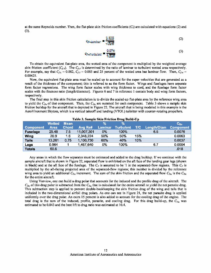
at the same Reynolds number. Then, the flat-plate skin friction coefficients (Cf) are calculated with equations (2) and(3).
(2)
r:,i , , ^(3)
.5'C7
To obtain the equivalent flat-plate area, the wetted area of the component is multiplied by the weighted averageskin friction coefficient ( Cf-A). The Cf-A is determined by the ratio of laminar to turbulent wetted area respectively.For example, say that Cf-L = 0.002, Cf-T = 0.005 and 25 percent of the wetted area has laminar flow. Then, Cf-A =0.00425.
Now, the equivalent flat-plate area must be scaled up to account for the super velocities that are generated as aresult of the thickness of the component; this is referred to as the form factor. Wings and fuselages have separateform factor regressions. The wing form factor scales with wing thickness to cord, and the fuselage form factorscales with the fineness ratio (length/diameter). Figures 6 and 7 in reference 1 contain body and wing form factors,respectively.
The final step in this skin friction calculation is to divide the scaled-up flat-plate area by the reference wing areato yield the CD,, of that component. Then, the CD,, are summed for each component. Table 3 shows a sample skinfriction buildup for the aircraft that is depicted in Figure 22. The aircraft that is being modeled in this example is theAeroVironment Skytote, which is a vertical takeoff and landing (VTOL) tailsitter with counter-rotating propellers.
Table 3. Sample Skin Friction Drag
Fuselage 25.48 7.5 11,007,301 0% 100% 6.5 0.0076Wing 20.9 1.6 2,348,224 50% 50% 15% 0.0063Tails 13.261 0.75 1,100,730 60% 40% 10% 0.0037Legs 0.964 1 1,467,640 0% 100% 6.7 0.0004Totals 60.6 .018
Any areas in which the flow separates must be estimated and added to the drag buildup. If we continue with thesample aircraft that is shown in Figure 22, separated flow is exhibited on the aft face of the landing gear legs (shownin black) and at the aft face of the fuselage. The CP is assumed to be - 1 in the separated-flow regions. This CP ismultiplied by the aft-facing projected area of the separated-flow regions; this number is divided by the referencewing area to yield an additional CD,, increment. The sum of the skin friction and the separated flow CD,, is the CD,,
for the entire aircraft.Using Vorview, one can build a drag polar that accounts for the induced and the profile drag of the aircraft. The
CD,, of this drag polar is subtracted from the CD,, that is calculated for the entire aircraft to yield the net parasite drag.This subtraction step is applied to prevent double-bookkeeping the skin friction drag of the wing and tails that isincluded in the two-dimensional airfoil drag polars. As one can see in Figure 21, the net parasite drag is applieduniformly over the drag polar. An extra 15 percent is also added to account for the cooling drag of the engine. Thetotal drag is the sum of the induced, profile, parasite, and cooling drag. For this drag build-up, the CD,, wasestimated to be 0.043 and the best lift to drag ratio was estimated at 10.4.
12American Institute of Aeronautics and Astronautics
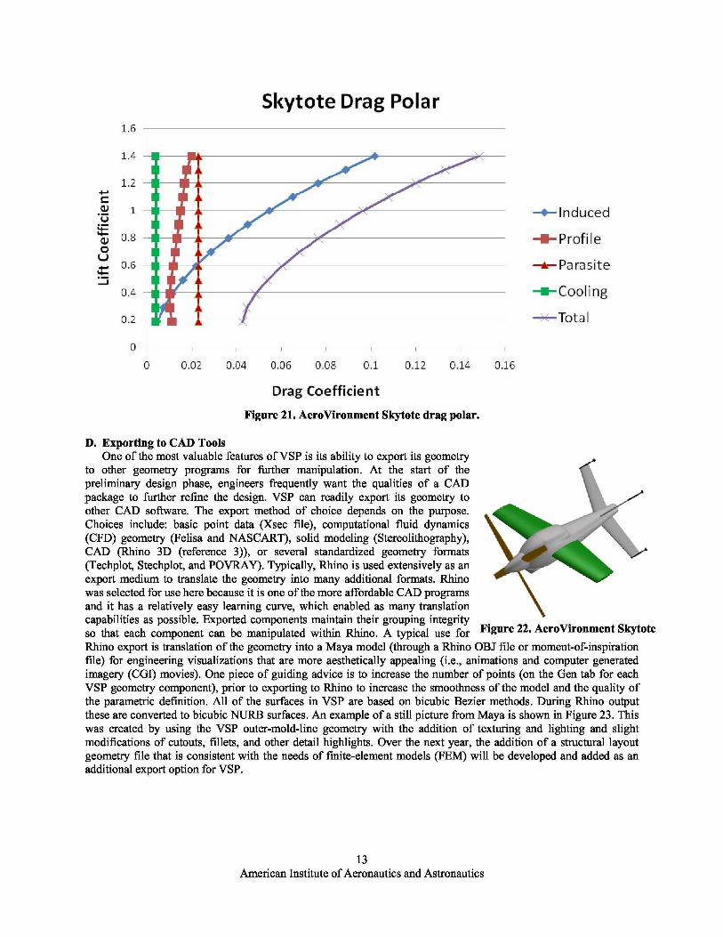
Figure 22. AeroVironment Skytote
Figure 21. AeroVironment Skytote drag polar.
D. Exporting to CAD ToolsOne of the most valuable features of VSP is its ability to export its geometry
to other geometry programs for further manipulation. At the start of thepreliminary design phase, engineers frequently want the qualities of a CADpackage to further refine the design. VSP can readily export its geometry toother CAD software. The export method of choice depends on the purpose.Choices include: basic point data (Xsec file), computational fluid dynamics(CFD) geometry (Felisa and NASCART), solid modeling (Stereolithography),CAD (Rhino 3D (reference 3)), or several standardized geometry formats(Techplot, Stechplot, and POVRAY). Typically, Rhino is used extensively as anexport medium to translate the geometry into many additional formats. Rhinowas selected for use here because it is one of the more affordable CAD programsand it has a relatively easy learning curve, which enabled as many translationcapabilities as possible. Exported components maintain their grouping integrityso that each component can be manipulated within Rhino. A typical use forRhino export is translation of the geometry into a Maya model (through a Rhino OBJ file or moment-of-inspirationfile) for engineering visualizations that are more aesthetically appealing (i.e., animations and computer generatedimagery (CGI) movies). One piece of guiding advice is to increase the number of points (on the Gen tab for eachVSP geometry component), prior to exporting to Rhino to increase the smoothness of the model and the quality ofthe parametric definition. All of the surfaces in VSP are based on bicubic Bezier methods. During Rhino outputthese are converted to bicubic NURB surfaces. An example of a still picture from Maya is shown in Figure 23. Thiswas created by using the VSP outer-mold-line geometry with the addition of texturing and lighting and slightmodifications of cutouts, fillets, and other detail highlights. Over the next year, the addition of a structural layoutgeometry file that is consistent with the needs of finite-element models (FEM) will be developed and added as anadditional export option for VSP.
13American Institute of Aeronautics and Astronautics

Figure 23. Sample Maya model taken from VSP geometry.
V. Conclusion
Having a geometry tool such as VSP as the center of a conceptual design methodology promotes a more rapidconceptual design cycle. If all other tools, such as weights, aerodynamics, performance, and so on, are able to pulltheir geometric inputs from one central geometry tool, then for each design iteration, subsequent tools have the mostcurrent geometry. This reduces configuration version errors. As a geometry model is built, a degree of realism isadded to the design because geometric constraints that have not been anticipated initially become apparent. Becausethe conceptual designer can more rapidly visualize the concept, problems can be addressed earlier in the designprocess. This is all made possible by the short learning curve of VSP, allowing the conceptual designer to make useof a geometry centered tool earlier in the design process.
14American Institute of Aeronautics and Astronautics

Figure A1. Aerosonde Laima.
Figure A2. AeroVironment Skytote.
Appendix A. Selected Models from Learning Curve Study
Figure A3. General Atomics Predator A. Figure A4. Lockheed SR-71.
Figure A5. MLB V-Bat. Figure A6. VTOL Technologies, Ltd. Ducted FanUAV.
15American Institute of Aeronautics and Astronautics

Appendix B. Detailed Instructions for the Creation of the MLB V-BatIn building a model of an existing aircraft, the first step in the process is to find a 3-view drawing of the aircraft.
For the case of the MLB V-Bat, a three view was not available, but a SolidWorks Model was obtained. InSolidWorks drawings, it is possible to take screenshots of the model in different views, so these images were savedas .jpg files and inserted into the background of the VSP main window.
1. Open VSP2. Go to “Window” at top, Select “Background”3. In the Background window, select JPEG Image. This will bring up a window to find the .jpg image
you would like to insert as the background. Select your model’s side view and click “OK”4. The most common part to start with when building an aircraft model is the fuselage, as this is what
most other components connect to. Go to the Geom Window and find the Fuse item from the dropdown menu. Click the Add button.
5. If the length of the fuselage is known, go to the Shape tab in the Fuselage Geom window and typelength into the length field (the preset value is 30). For the case of the V-Bat, 66.17 is entered.
6. While pushing both mouse buttons, push the mouse forward (this will zoom out). Pushing the mousebackward will zoom in. Pushing only the right hand button will translate the model, and pushing onlythe left hand button will rotate the model. For now, only use the zoom and translate functions. Alignthe fuselage up with the fuselage of the background.
7. Next, go to the XSec tab. Change the height and width of Cross Sections 1, 2 and 3 by entering thediameter of the fuselage into the field. In this case, 8 is entered. To switch between cross sections,push the arrows to the right of “Cross Section ID” located at the top of the tab.
8. Add XSections to increase the accuracy of the model. To do this, go to Cross Section ID 1 and clickthe Add button. The new section will be added to the right of the selected cross section. Obtain a totalof 8 cross sections, evenly spaced out. To move a cross section, slide the Location slider.
9. Next, we will get the nose and tail cone shaped correctly. Select the Shape tab and, about mid-waydown, two sliders will be found called Nose Rho and Aft Rho. Slide these until the desired shape isachieved.
10. We will now leave the fuselage alone for awhile, as the general shape has been established. Let’s addthe wing next. In the Geom Browser, select MS Wing from the drop down menu and click Add.
11. Change the background image to the top view.12. Zoom out to re-adjust the model to line up with the background.13. Change the color of the wing to make it stand out from the fuselage. This is done in the Gen tab by
selecting the color desired.14. Rename the fuselage and wing to something approiate by changing the name in the Gen tab. This will
help keep your parts list organized, especially when multiples of the same part are used.15. Click on the wing part in the Geom Browser and go to the Sect tab. Change the Section ID by
pushing the arrow to the right of the number. Delete Sections 2 and then 1.16. Change the wingspan to 122.0. To do this, go to the Plan tab and type in 122.0 for the span. Next, you
will have to take out the wing sweep. Go to the Sect tab. Lower on the screen it will have a Sweepslider. Simply highlight the 65 preset value and type in 0.
17. Move the wing to its proper position on the fuselage. Go to the XForm tab and move the X Loc sliderall the way to the right. When you reach the end of the slider track, simply type in a larger number andit will allow the wing to move further. For this vehicle, 48.8 is sufficient.
18. Next change the chord length of the wing. Go to the Plan tab and move the Chord slider until trailingedge of the wing lines up with the background image.
19. Add a duct. In the Geom Browser, choose Duct from the pull down menu. Click Add. Reposition thefuselage to match up with the background image. Go to the XForm tab for the Duct and move the XLocation to line up with the background image.
20. Tip you can store view angles on the F1 to F4 keys. Hold down Shift then push one of the functionkeys. If you make a mistake and it appears the view has locked up press the letter C key.
21. Change the Inlet Diameter of the Duct by going to the Shape tab and typing in 29.6 (from thedimension drawing of the V-Bat). Next, Change the Inlet/Outlet Ratio to 1.22 (29.6 / 24.25 = 1.22) bytyping 1.22 into the field. Finally, change the length of the Duct until it lines up with the backgroundpicture. For this case, it is about 7.86.
16American Institute of Aeronautics and Astronautics
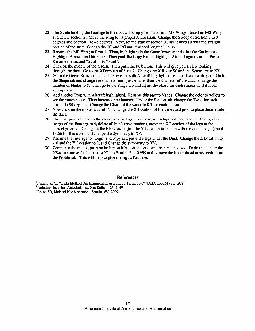
22. The Struts holding the fuselage to the duct will simply be made from MS Wings. Insert an MS Wingand delete section 2. Move the wing to its proper X Location. Change the Sweep of Section 0 to 0degrees and Section 1 to 45 degrees. Next, set the span of section 0 until it lines up with the straightportion of the strut. Change the TC and RC until the cord lengths line up.
23. Rename the MS Wing to Strut 1. Then, highlight it in the Geom browser and click the Cut button.Highlight Aircraft and hit Paste. Then push the Copy button, highlight Aircraft again, and hit Paste.Rename the second “Strut 1” to “Strut 2.”
24. Click on the middle of the screen. Then push the F6 button. This will give you a view lookingthrough the duct. Go to the XForm tab of Strut 2. Change the X Rot to 90 and the Symmetry to XY.
25. Go to the Geom Browser and add a propeller with Aircraft highlighted so it loads as a child part. Go tothe Shape tab and change the diameter until just smaller than the diameter of the duct. Change thenumber of blades to 8. Then go to the Shape tab and adjust the chord for each station until it looksappropriate.
26. Add another Prop with Aircraft highlighted. Rename this part to Vanes. Change the color to yellow tosee the vanes better. Then increase the diameter. Under the Station tab, change the Twist for eachstation to 90 degrees. Change the Chord of the vanes to 0.3 for each station.
27. Now click on the model and hit F5. Change the X Location of the vanes and prop to place them insidethe duct.
28. The final pieces to add to the model are the legs. For these, a fuselage will be inserted. Change thelength of the fuselage to 4, delete all but 3 cross sections, move the X Location of the legs to thecorrect position. Change to the F10 view, adjust the Y Location to line up with the duct’s edge (about13.66 for this case), and change the Symmetry to XZ.
29. Rename the fuselage to “Legs” and copy and paste the legs under the Duct. Change the Z Location to-10 and the Y Location to 0, and Change the symmetry to XY.
30. Zoom into the model, pushing both mouth buttons at once, and reshape the legs. To do this, under theXSec tab, move the location of Cross Section 2 to 0.999 and remove the interpolated cross sections onthe Profile tab. This will help to give the legs a flat base.
References1 Feagin, R. C., “Delta Method, An Empirical Drag Buildup Technique,” NASA CR-151971, 1978.2Autodesk Inventor, Autodesk, Inc. San Rafael, CA, 20093Rhino 3D, McNeel North America, Seattle, WA 2009
17American Institute of Aeronautics and Astronautics