agilent 1100 series hplc value system user's guide
TRANSCRIPT
sa
Agilent 1100 SeriesHPLC Value System
User’s Guide
Agilent TechnologiesHewlett-Packard-Strasse 876337 WaldbronnGermany
Copyright Agilent Technologies 1999
All rights reserved. Reproduction, adaption, or translation without prior written permission is prohibited, except as allowed under the copyright laws.
Part No. G1380-90000
Edition 11/99
Printed in Germany
Warranty
The information contained in this document is subject to change without notice.
Agilent Technologies
makes no warranty of
any kind with regard to
this material,
including, but not
limited to, the implied
warranties or
merchantability and
fitness for a particular
purpose.
Agilent Technologies shall not be liable for errors contained herein or for incidental or consequential damages in connection with the furnishing, performance, or use of this material.
WARNING
For details of safety, see Safety Information on page 36.
Warning Symbols Used
In This Book
The apparatus is marked with this symbol when the user should refer to the instruction manual in order to protect the apparatus against damage.
!

User’s Guide
Agilent 1100 Series HPLC Value System
4
In This Book
This manual contains technical information about the Agilent 1100 Series HPLC Value System. The manual describes the following:
• system overview, specifications and limitations
• installing the system,
• setting up an analysis,
• diagnostics and troubleshooting,
• repairing and maintenance
Contents
1 General information about your system
System Configuration 1010
System Restrictions 11Site Requirements 12Physical Specifications 14Performance Specifications 15Maintenance, Repair and Parts Information 15Warranty and Legal Information 15User Documentation 16
2 Installing your System
Unpacking the Modules 18Damaged Packaging 18Delivery Checklist 18
Installing the JetDirect card into the VW detector 19Choose the optimal stack configuration 20Installing the Manual Injector and 1100 series HPLC modules 21Flow Connections at the Manual Injector 24
Leak Drainage of the Manual Injector 25
Flow Connections at the Isocratic Pump 26Flow Connections to the VW Detector 28Installing the ChemStation Hardware 30Booting the PC for the First Time 31Installing the LAN Communication 32
Configuring the CAG Bootp Server Program 32
Configuring the Analytical System 35
5
Contents
3 Setting up an Analysis
Before Using the System 41Solvent Information 41Priming and Purging the System 41
Requirements and Conditions 43What You Will Need 43Conditions 43Typical Chromatogram 44Optimization of the System 44
Preparing the HPLC System 45Running the Sample and Verifying the Results 50
4 Troubleshooting your System
Diagnostic Functions 53Status Information on the 1100 Modules 53
Online System Information 54Instrument Logbook and Help Information 56Using Module Diagnosis 57Using Module Tests 58Problems during the Installation 59
5 Repair and Maintenance
Repair and Parts Information for the 1100 series HPLC Modules 62Firmware Update on 1100 Modules 63Deinstallation and Reinstallation of the ChemStation 64Recovering from an Operating System Crash 65
Process steps 65
6
Contents
Step 1: Installation of Windows NT 65Step 2: Installation of TCP/IP protocol 66Step 3: Re-installation of Windows NT Service Pack 69Step 4: Installation of Value Solution ChemStation 69Step 5: Installation of the Bootp Server Program 69Step 6: Configuring the CAG Bootp Server Program 69
7

Contents
8
1
1 General information
about your system
What you should know about your system
General information about your systemSystem Configuration
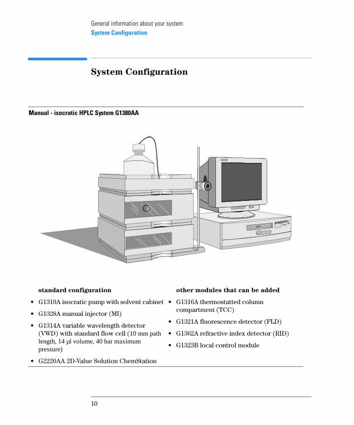
System Configuration
Manual - isocratic HPLC System G1380AA
standard configuration
• G1310A isocratic pump with solvent cabinet
• G1328A manual injector (MI)
• G1314A variable wavelength detector (VWD) with standard flow cell (10 mm path length, 14 µl volume, 40 bar maximum pressure)
• G2220AA 2D-Value Solution ChemStation
other modules that can be added
• G1316A thermostatted column compartment (TCC)
• G1321A fluorescence detector (FLD)
• G1362A refractive index detector (RID)
• G1323B local control module
10
General information about your systemSystem Restrictions
System Restrictions
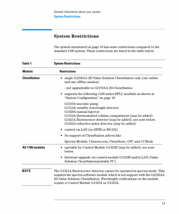
The system mentioned on page 10 has some restrictions compared to the standard 1100 system. These restrictions are listed in the table below:
NOTE The G1321A fluorescence detector cannot be operated in spectra mode. This requires the spectra software module which is not support with the G2220AA 2D-Value Solution ChemStation. Wavelength verifications on the module require a Control Module G1323A or G1323A.
Table 1 System Restrictions
Module Restrictions
ChemStation • single G2220AA 2D-Value Solution ChemStation only (one online and one offline session)
- not upgradeable to G2170AA 2D-ChemStation
• supports the following 1100 series HPLC modules as shown in “System Configuration” on page 10:
G1310A isocratic pumpG1314A variable wavelength detectorG1328A manual injectorG1316A thermostatted column compartment (may be added)G1321A fluorescence detector (may be added), see note below.G1362A refractive index detector (may be added)
• control via LAN (no HPIB or RS-232)
• No support of ChemStation add-on like
Spectra Module, ChemAccess, ChemStore, GPC and CCMode
All 1100 modules • operable by Control Module G1323B (may be added), see note below.
• firmware upgrade via control module G1323B and/or LAN (Value Solution ChemStation/portable PC).
11
General information about your systemSite Requirements
Site Requirements
A suitable environment is important to ensure optimum performance of the system.
Power Consideration
The modules’ power supply has wide-ranging capability (see Table 2 on page 14). It accepts any line voltage in the above mentioned range. Consequently there is no voltage selector in the rear of the modules. There are also no externally accessible fuses, because automatic electronic fuses are implemented in the power supply.
WARNING To disconnect the modules from line, unplug the power cord. The
power supply still uses some power, even if the power switch on the
front panel is turned off.
WARNING Shock hazard or damage of your instrumentation can result, if the
devices are connected to a line voltage higher than specified.
Power Cords
Different power cords are offered as options with the modules. The female end of each of the power cords is identical. It plugs into the power-input socket at the rear of the instruments. The male end of each of the power cords is different and designed to match the wall socket of a particular country or region.
WARNING Never operate your instrumentation from a power outlet that has no
ground connection. Never use a power cord other than the power cord
designed for your region.
WARNING Never use cables other than the ones supplied with the instruments to
ensure proper functionality and compliance with safety or EMC
regulations.
12
General information about your systemSite Requirements
Bench Space
The modules’ dimensions and weight (see Table 2 on page 14) allow to place the modules on almost any desk or laboratory bench. It needs an additional 2.5 cm (1.0 inches) of space on either side and approximately 8 cm (3.1 inches) in the rear for the circulation of air and electric connections.
If the bench should carry a complete system, make sure that the bench is designed to carry the weight of all the modules.
The modules should be operated in a horizontal position.
Environment
Your modules will work within specifications at ambient temperatures and relative humidity as described in Table 2 on page 14.
Detectors
ASTM drift tests require a temperature change below 2 °C/hour (3.6 °F/hour) over one hour period. Our published drift specification (refer also to “Performance Specifications” in your detector’s reference manuals) is based on these conditions. Larger ambient temperature changes will result in larger drift. Better drift performance depends on better control of the temperature fluctuations. To realize the highest performance, minimize the frequency and the amplitude of the temperature changes to below 1 °C/hour (1.8 °F/hour). Turbulences around one minute or less can be ignored.
CA UTIO N Do not store, ship or use your modules under conditions where temperature fluctuations could cause condensation within the modules. Condensation will damage the system electronics. If your modules were shipped in cold weather, leave them in their boxes and allow them to warm slowly to room temperature to avoid condensation.
13
General information about your systemPhysical Specifications
Physical Specifications
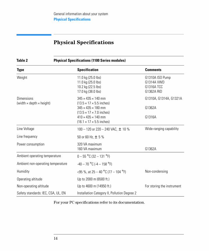
For your PC specifications refer to its documentation.
Table 2 Physical Specifications (1100 Series modules)
Type Specification Comments
Weight 11.0 kg (25.0 lbs)11.0 kg (25.0 lbs)10.2 kg (22.5 lbs)17.0 kg (38.0 lbs)
G1310A ISO PumpG1314A VWDG1316A TCCG1362A RID
Dimensions(width × depth × height)
345 × 435 × 140 mm(13.5 × 17 × 5.5 inches)345 × 435 × 180 mm(13.5 × 17 × 7.0 inches)410 × 435 × 140 mm(16.1 × 17 × 5.5 inches)
G1310A, G1314A, G1321A
G1362A
G1316A
Line Voltage 100 – 120 or 220 – 240 VAC, ± 10 % Wide-ranging capability
Line frequency 50 or 60 Hz, ± 5 %
Power consumption 320 VA maximum160 VA maximum G1362A
Ambient operating temperature 0 – 55 °C (32 – 131 °F)
Ambient non-operating temperature -40 – 70 °C (-4 – 158 °F)
Humidity <95 %, at 25 – 40 °C (77 – 104 °F) Non-condensing
Operating altitude Up to 2000 m (6500 ft.)
Non-operating altitude Up to 4600 m (14950 ft.) For storing the instrument
Safety standards: IEC, CSA, UL, EN Installation Category II, Pollution Degree 2
14
General information about your systemPerformance Specifications
Performance Specifications
The performance specifications can be derived from the modules’ performance specifications, described in each of the modules’ reference manuals (see “User Documentation” on page 16 available on your Value
Solution ChemStation Software CD-ROM).
Maintenance, Repair and Parts
Information
The information about these topics can be derived from the corresponding chapters in each of the modules’ reference manuals (see “User Documentation” on page 16 available on your Value Solution ChemStation
Software CD-ROM).
Warranty and Legal Information
For warranty and legal information refer to the modules’ reference manuals, see “User Documentation” on page 16 available on your Value Solution
ChemStation Software CD-ROM).
15
General information about your systemUser Documentation
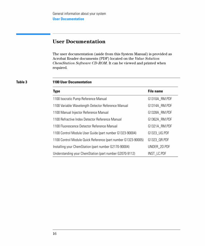
User Documentation
The user documentation (aside from this System Manual) is provided as Acrobat Reader documents (PDF) located on the Value Solution
ChemStation Software CD-ROM. It can be viewed and printed when required.
Table 3 1100 User Documentation
Type File name
1100 Isocratic Pump Reference Manual G1310A_RM.PDF
1100 Variable Wavelength Detector Reference Manual G1314A_RM.PDF
1100 Manual Injector Reference Manual G1328A_RM.PDF
1100 Refractive Index Detector Reference Manual G1362A_RM.PDF
1100 Fluorescence Detector Reference Manual G1321A_RM.PDF
1100 Control Module User Guide (part number G1323-90004) G1323_UG.PDF
1100 Control Module Quick Reference (part number G1323-90005) G1323_QR.PDF
Installing your ChemStation (part number G2170-90004) UNDER_2D.PDF
Understanding your ChemStation (part number G2070-9112) INST_LC.PDF
16
2
2 Installing your System
How to install your system
Installing your SystemUnpacking the Modules
Unpacking the Modules
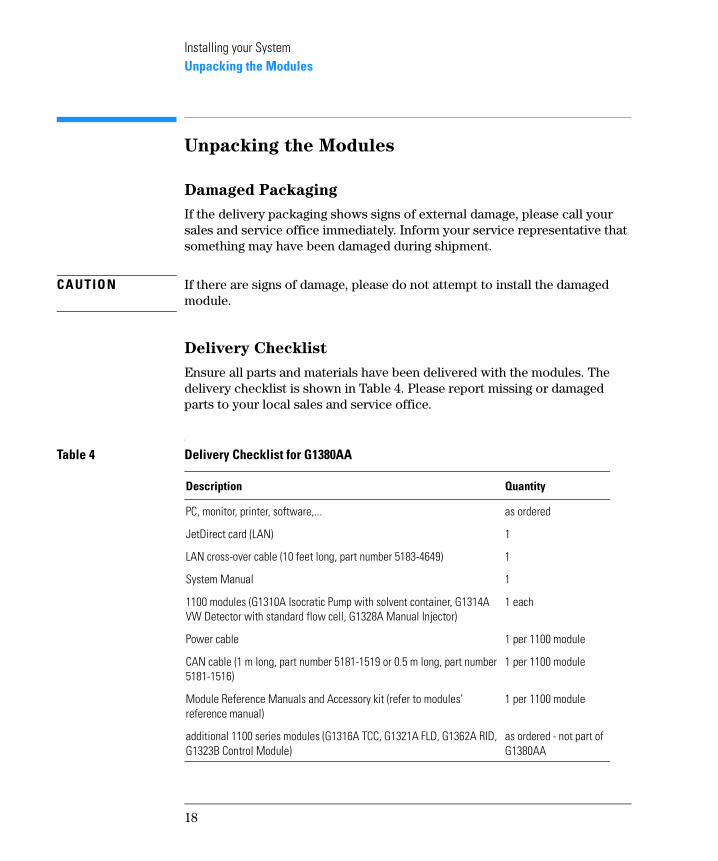
Damaged Packaging
If the delivery packaging shows signs of external damage, please call your sales and service office immediately. Inform your service representative that something may have been damaged during shipment.
CA UTIO N If there are signs of damage, please do not attempt to install the damaged module.
Delivery Checklist
Ensure all parts and materials have been delivered with the modules. The delivery checklist is shown in Table 4. Please report missing or damaged parts to your local sales and service office.
Table 4 Delivery Checklist for G1380AA
Description Quantity
PC, monitor, printer, software,... as ordered
JetDirect card (LAN) 1
LAN cross-over cable (10 feet long, part number 5183-4649) 1
System Manual 1
1100 modules (G1310A Isocratic Pump with solvent container, G1314A VW Detector with standard flow cell, G1328A Manual Injector)
1 each
Power cable 1 per 1100 module
CAN cable (1 m long, part number 5181-1519 or 0.5 m long, part number 5181-1516)
1 per 1100 module
Module Reference Manuals and Accessory kit (refer to modules’ reference manual)
1 per 1100 module
additional 1100 series modules (G1316A TCC, G1321A FLD, G1362A RID, G1323B Control Module)
as ordered - not part of G1380AA
18
Installing your SystemInstalling the JetDirect card into the VW detector
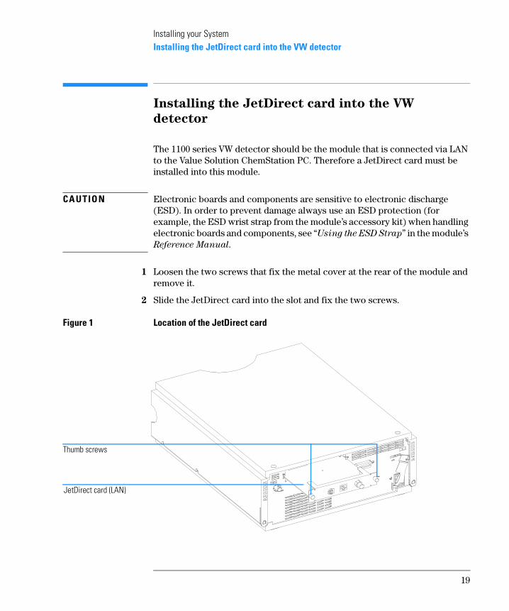
Installing the JetDirect card into the VW
detector
The 1100 series VW detector should be the module that is connected via LAN to the Value Solution ChemStation PC. Therefore a JetDirect card must be installed into this module.
CA UTIO N Electronic boards and components are sensitive to electronic discharge (ESD). In order to prevent damage always use an ESD protection (for example, the ESD wrist strap from the module’s accessory kit) when handling electronic boards and components, see “Using the ESD Strap” in the module’s Reference Manual.
1 Loosen the two screws that fix the metal cover at the rear of the module and remove it.
2 Slide the JetDirect card into the slot and fix the two screws.
Figure 1 Location of the JetDirect card
JetDirect card (LAN)
Thumb screws
19
Installing your SystemChoose the optimal stack configuration
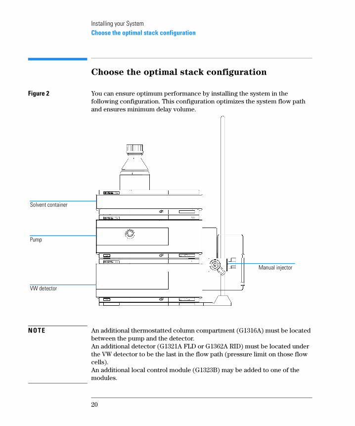
Choose the optimal stack configuration
Figure 2 You can ensure optimum performance by installing the system in the following configuration. This configuration optimizes the system flow path and ensures minimum delay volume.
NOTE An additional thermostatted column compartment (G1316A) must be located between the pump and the detector.An additional detector (G1321A FLD or G1362A RID) must be located under the VW detector to be the last in the flow path (pressure limit on those flow cells).An additional local control module (G1323B) may be added to one of the modules.
Solvent container
Pump
VW detector
Manual injector
20
Installing your SystemInstalling the Manual Injector and 1100 series HPLC modules
Installing the Manual Injector and 1100
series HPLC modules
NOTE Assure that all power switches on the 1100 HPLC modules are in OFF (out) position.
NOTE The manual injector can be installed at the left- or right-hand side of the instrument stack.
1 Place the base plate on the bench.
2 Screw the mounting pole into one of the three holes in the base plate.
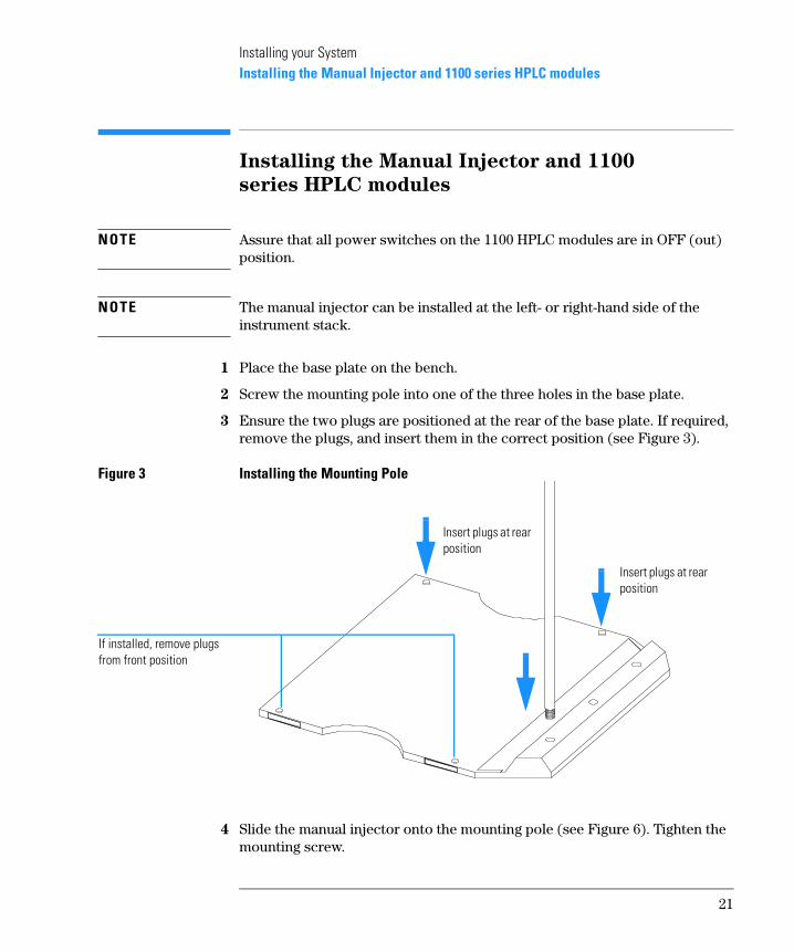
3 Ensure the two plugs are positioned at the rear of the base plate. If required, remove the plugs, and insert them in the correct position (see Figure 3).
Figure 3 Installing the Mounting Pole
4 Slide the manual injector onto the mounting pole (see Figure 6). Tighten the mounting screw.
Insert plugs at rear position
Insert plugs at rear position
If installed, remove plugs from front position
21
Installing your SystemInstalling the Manual Injector and 1100 series HPLC modules
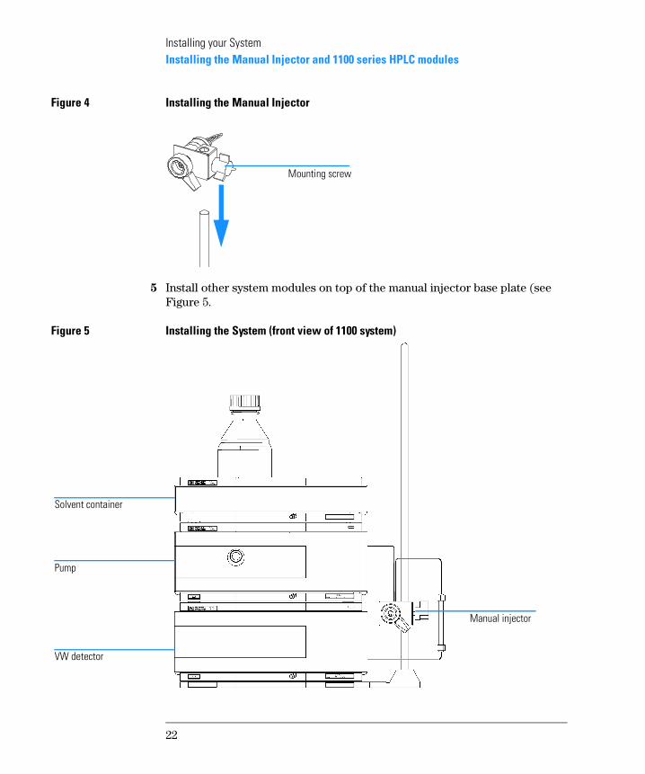
Figure 4 Installing the Manual Injector
5 Install other system modules on top of the manual injector base plate (see Figure 5.
Figure 5 Installing the System (front view of 1100 system)
Mounting screw
Solvent container
Pump
VW detector
Manual injector
22
Installing your SystemInstalling the Manual Injector and 1100 series HPLC modules
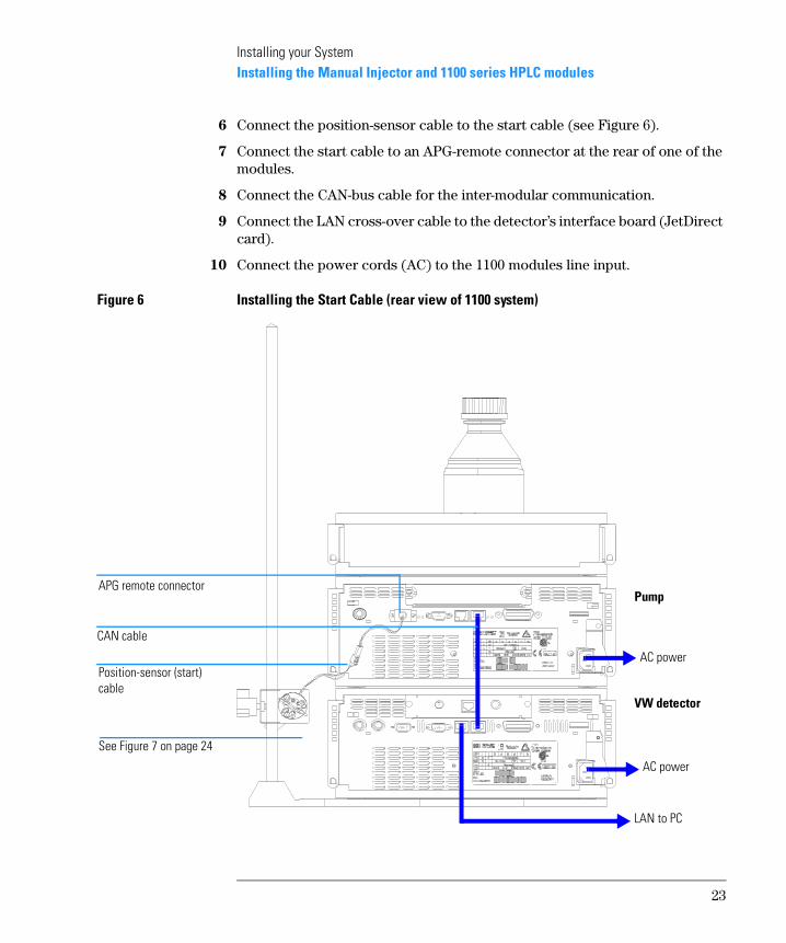
6 Connect the position-sensor cable to the start cable (see Figure 6).
7 Connect the start cable to an APG-remote connector at the rear of one of the modules.
8 Connect the CAN-bus cable for the inter-modular communication.
9 Connect the LAN cross-over cable to the detector’s interface board (JetDirect card).
10 Connect the power cords (AC) to the 1100 modules line input.
Figure 6 Installing the Start Cable (rear view of 1100 system)
Position-sensor (start) cable
APG remote connector
See Figure 7 on page 24
AC power
AC power
LAN to PC
Pump
VW detector
CAN cable
23
Installing your SystemFlow Connections at the Manual Injector
Flow Connections at the Manual Injector
WARNING When opening capillary or tube fittings, solvents may leak out. Please
observe appropriate safety procedures (for example, goggles, safety
gloves and protective clothing) as described in the material handling
and safety data sheet supplied by the solvent vendor, especially when
toxic or hazardous solvents are used (see also “Leak Drainage of the
Manual Injector” on page 25).
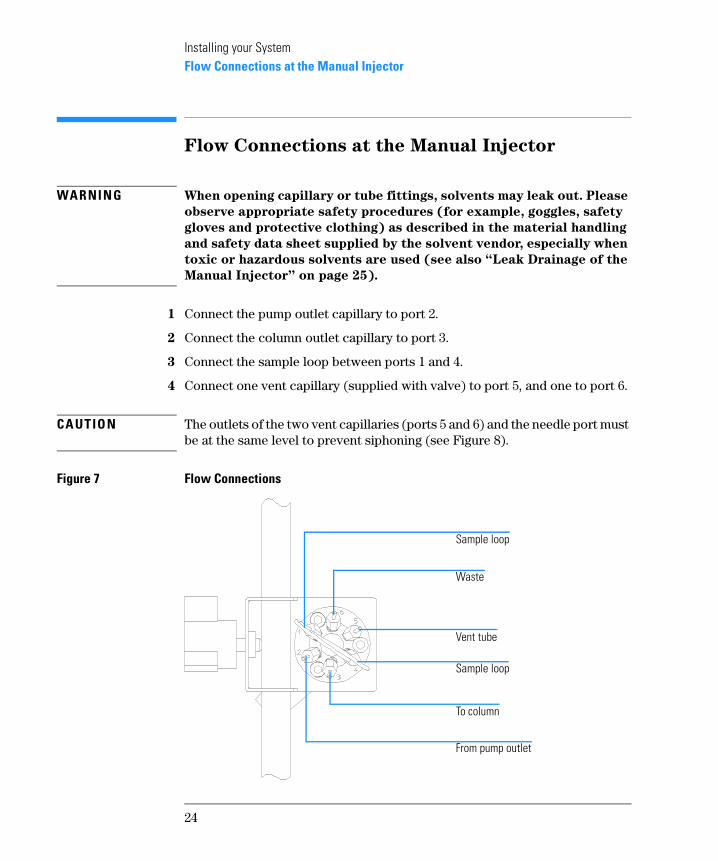
1 Connect the pump outlet capillary to port 2.
2 Connect the column outlet capillary to port 3.
3 Connect the sample loop between ports 1 and 4.
4 Connect one vent capillary (supplied with valve) to port 5, and one to port 6.
CA UTIO N The outlets of the two vent capillaries (ports 5 and 6) and the needle port must be at the same level to prevent siphoning (see Figure 8).
Figure 7 Flow Connections
Sample loop
Waste
Vent tube
Sample loop
To column
From pump outlet
24

Installing your SystemFlow Connections at the Manual Injector
Figure 8 Vent Capillaries
Leak Drainage of the Manual Injector
WARNING Check the manual injector fittings periodically for signs of leakage. In
the event of a leak, solvent will drop into the leak channel in the base
plate, from where it is channelled to the front and back of the base
plate.
Figure 9 Leak Drainage
Vent capillaries (ports 5 and 6)
Vent capillaries and needle port at the same level
Leak channel
25
Installing your SystemFlow Connections at the Isocratic Pump
Flow Connections at the Isocratic Pump
WARNING When opening capillary or tube fittings, solvents may leak out. Please
observe appropriate safety procedures (for example, goggles, safety
gloves and protective clothing) as described in the material handling
and safety data sheet supplied by the solvent vendor, especially when
toxic or hazardous solvents are used.
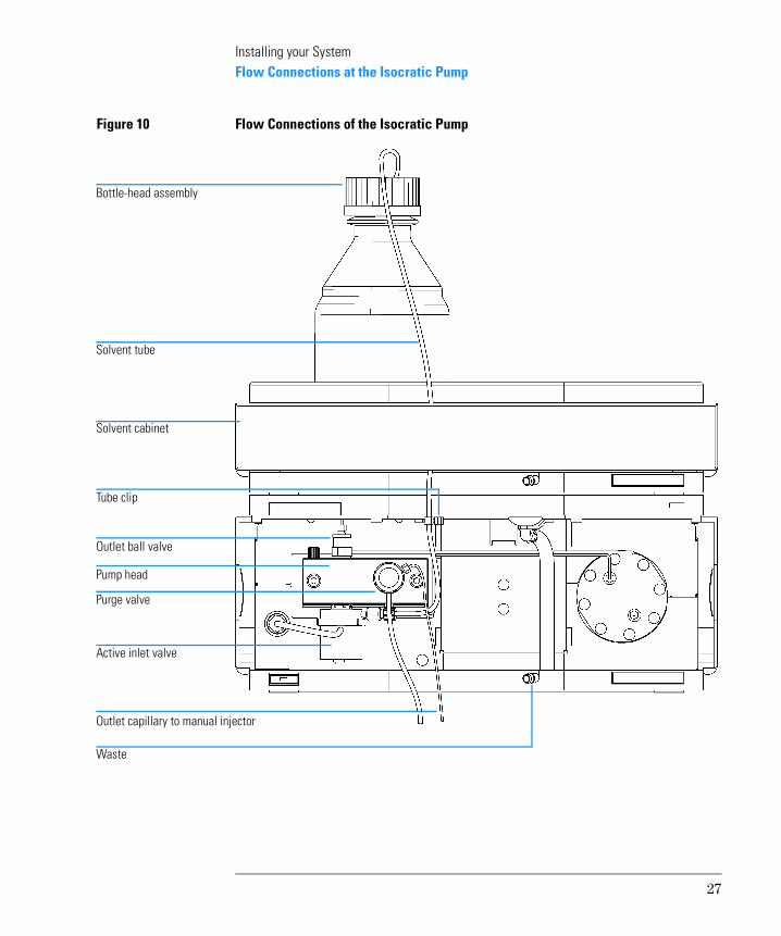
1 Remove the front cover by pressing the snap fasteners on both sides.
2 Place the solvent cabinet on top of the isocratic pump (Figure 10 on page 27.
3 Place the bottle containing your solvent into the solvent cabinet and place the bottle-head assembly into the bottle.
4 Connect the solvent tube from the bottle-head assembly to the inlet adapter of the active inlet valve. Fix the tube in the clips of solvent cabinet and isocratic pump.
5 Using a piece of sanding paper connect the waste tubing to the purge valve and place it into your waste system.
6 Connect the outlet capillary (isocratic pump to manual injection valve) to the outlet of the purge valve.
Preparations Pump is installed in the HPLC system.
Parts required Other modulesParts from accessory kit G1310-68705Two wrenches 1/4–5/16 inch for capillary connections
26
Installing your SystemFlow Connections at the Isocratic Pump
Figure 10 Flow Connections of the Isocratic Pump
Bottle-head assembly
Solvent tube
Outlet capillary to manual injector
Waste
Pump head
Outlet ball valve
Active inlet valve
Purge valve
Tube clip
Solvent cabinet
27
Installing your SystemFlow Connections to the VW Detector
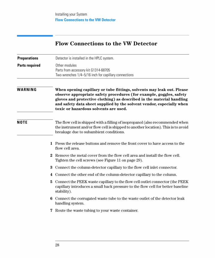
Flow Connections to the VW Detector
WARNING When opening capillary or tube fittings, solvents may leak out. Please
observe appropriate safety procedures (for example, goggles, safety
gloves and protective clothing) as described in the material handling
and safety data sheet supplied by the solvent vendor, especially when
toxic or hazardous solvents are used.
NOTE The flow cell is shipped with a filling of isopropanol (also recommended when the instrument and/or flow cell is shipped to another location). This is to avoid breakage due to subambient conditions.
1 Press the release buttons and remove the front cover to have access to the flow cell area.
2 Remove the metal cover from the flow cell area and install the flow cell. Tighten the cell screws (see Figure 11 on page 29).
3 Connect the column-detector capillary to the flow cell inlet connector.
4 Connect the other end of the column-detector capillary to the column.
5 Connect the PEEK waste capillary to the flow cell outlet connector (the PEEK capillary introduces a small back pressure to the flow cell for better baseline stability).
6 Connect the corrugated waste tube to the waste outlet of the detector leak handling system.
7 Route the waste tubing to your waste container.
Preparations Detector is installed in the HPLC system.
Parts required Other modulesParts from accessory kit G1314-68705 Two wrenches 1/4–5/16 inch for capillary connections
28
Installing your SystemFlow Connections to the VW Detector
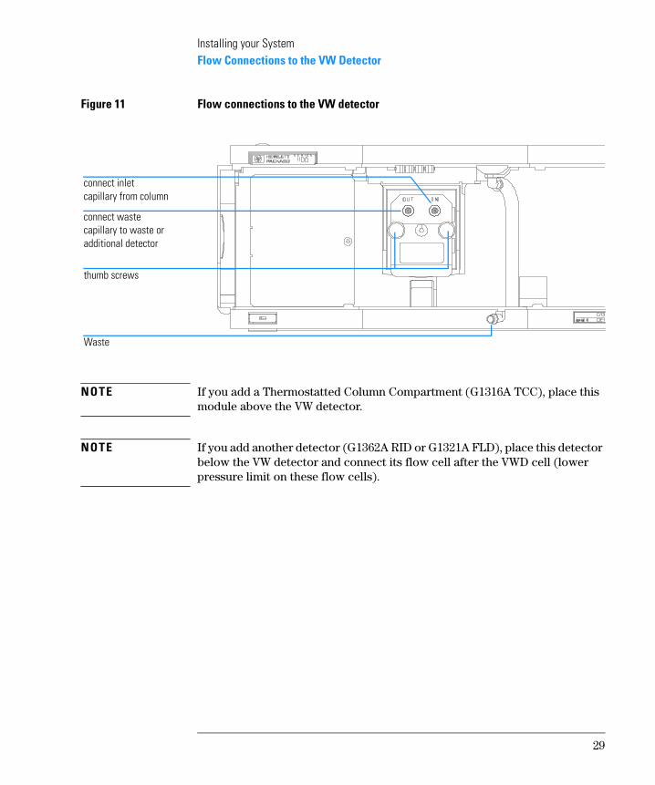
Figure 11 Flow connections to the VW detector
NOTE If you add a Thermostatted Column Compartment (G1316A TCC), place this module above the VW detector.
NOTE If you add another detector (G1362A RID or G1321A FLD), place this detector below the VW detector and connect its flow cell after the VWD cell (lower pressure limit on these flow cells).
connect inlet capillary from column
connect waste capillary to waste or additional detector
thumb screws
Waste
29
Installing your SystemInstalling the ChemStation Hardware
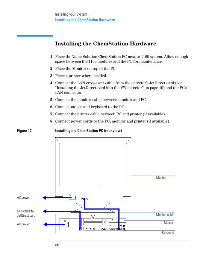
Installing the ChemStation Hardware
1 Place the Value Solution ChemStation PC next to 1100 system. Allow enough space between the 1100 modules and the PC for maintenance.
2 Place the Monitor on top of the PC.
3 Place a printer where needed.
4 Connect the LAN cross-over cable from the detector’s JetDirect card (see “Installing the JetDirect card into the VW detector” on page 19) and the PC’s LAN connector.
5 Connect the monitor cable between monitor and PC.
6 Connect mouse and keyboard to the PC.
7 Connect the printer cable between PC and printer (if available).
8 Connect power cords to the PC, monitor and printer (if available).
Figure 12 Installing the ChemStation PC (rear view)
AC power
LAN cable to JetDirect card
Monitor
Mouse
Keyboard
Monitor cable
AC power
30
Installing your SystemBooting the PC for the First Time
Booting the PC for the First Time
The Value Solution ChemStation PC has been factory pre-configured. This means that
• the operating system Windows NT 4.0,
• the Value Solution ChemStation software inclusive its required utilities, and
• further application
are already loaded on the hard disk. This configuration has been optimized for running the Value Solution ChemStation.
1 Turn on the monitor and the PC.
2 The PC will boot and stop at the Login Information screen. The pre-configured user is ‘Administrator’ and requires the password provided with your PC.
Note your password here: ______________
3 Then press OK.
4 The next screen shows ‘End User Licence Agreement’ information. Read the information and select I Agree and the PC will complete the boot process.
NOTE All activities necessary to change the user profile/logon under Windows NT are not subject of this manual. Refer to the Windows NT documentation.
31
Installing your SystemInstalling the LAN Communication
Installing the LAN Communication
Your instrument HPLC system is operated via a standard LAN crossover connection between the Value Solution ChemStation PC and the 1100 detector (VWD). You must ensure proper communication between the PC and the analytical instruments. The communication uses the TCP/IP protocol. For the configuration of the JetDirect card, that is used to connect the analytical instrument to the LAN, the Boot Strap protocol is used, which requires a Bootp Server.
NOTE The TCP/IP protocol and the Bootp Server program are already factory pre-installed.
Configuring the CAG Bootp Server Program
NOTE Assure that the VW detector (with JetDirect card installed and connected to the PC) is powered off.
1 The CAG Bootp Server program is placed in the start-up group and automatically is started during the boot process of the PC. It’s minimized and located in the task bar.
2 Open the Bootp Server window by clicking on it in the task bar.
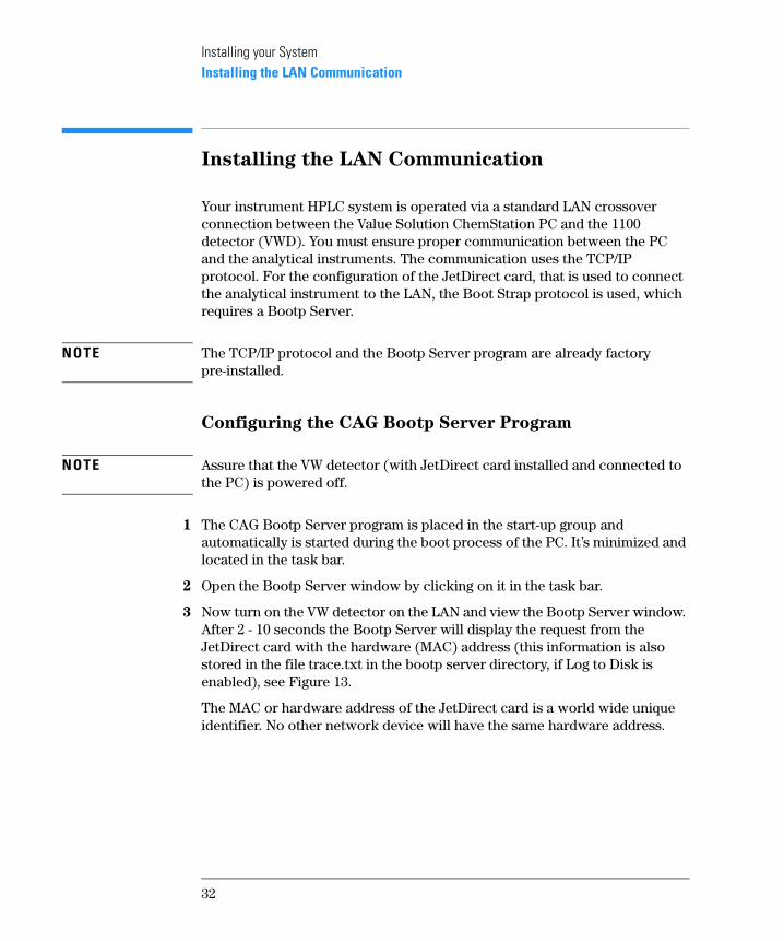
3 Now turn on the VW detector on the LAN and view the Bootp Server window. After 2 - 10 seconds the Bootp Server will display the request from the JetDirect card with the hardware (MAC) address (this information is also stored in the file trace.txt in the bootp server directory, if Log to Disk is enabled), see Figure 13.
The MAC or hardware address of the JetDirect card is a world wide unique identifier. No other network device will have the same hardware address.
32
Installing your SystemInstalling the LAN Communication
Figure 13 Bootp Server
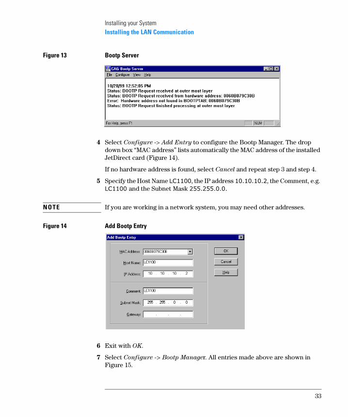
4 Select Configure -> Add Entry to configure the Bootp Manager. The drop down box “MAC address” lists automatically the MAC address of the installed JetDirect card (Figure 14).
If no hardware address is found, select Cancel and repeat step 3 and step 4.
5 Specify the Host Name ������, the IP address ����������, the Comment, e.g. �������and the Subnet Mask �������������
NOTE If you are working in a network system, you may need other addresses.
Figure 14 Add Bootp Entry
6 Exit with OK.
7 Select Configure -> Bootp Manager. All entries made above are shown in Figure 15.
33
Installing your SystemInstalling the LAN Communication
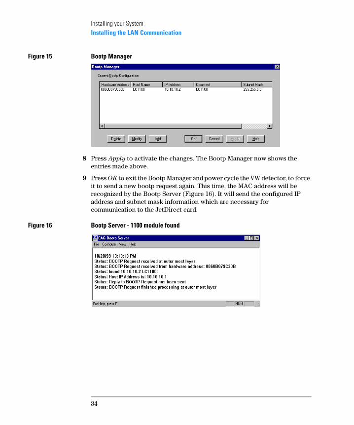
Figure 15 Bootp Manager
8 Press Apply to activate the changes. The Bootp Manager now shows the entries made above.
9 Press OK to exit the Bootp Manager and power cycle the VW detector, to force it to send a new bootp request again. This time, the MAC address will be recognized by the Bootp Server (Figure 16). It will send the configured IP address and subnet mask information which are necessary for communication to the JetDirect card.
Figure 16 Bootp Server - 1100 module found
34
Installing your SystemConfiguring the Analytical System
Configuring the Analytical System
This chapter describes how to configure the communication of your Value Solution ChemStation software with your LC instruments using a LAN connection with the ChemStation Configuration Editor. For details refer to the Installing your ChemStation manual supplied with your system.
The following example describes how to configure an 1100 Series system with modules interconnected by the 1100 Series controller area network (CAN) that will automatically configure each module.
NOTE Microsoft TCP/IP protocol must be installed and configured on the Value Solution ChemStation PC. In addition a Bootp Server must be running, which was configured for the instruments to be used.
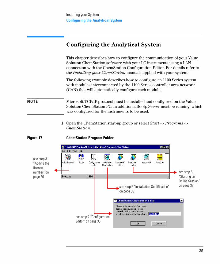
1 Open the ChemStation start-up group or select Start -> Programs ->
ChemStation.
Figure 17 ChemStation Program Folder
see step 5 “Starting an Online Session” on page 37
see step 3 “Adding the licence number” on page 36
see step 2 “Configuration Editor” on page 36
see step 5 “Installation Qualification” on page 36
35
Installing your SystemConfiguring the Analytical System
2 Start the ChemStation Configuration Editor (see Figure 17) and type in the IP address of the JetDirect card (�����������see also “Configuring the CAG Bootp Server Program” on page 32) and press OK.
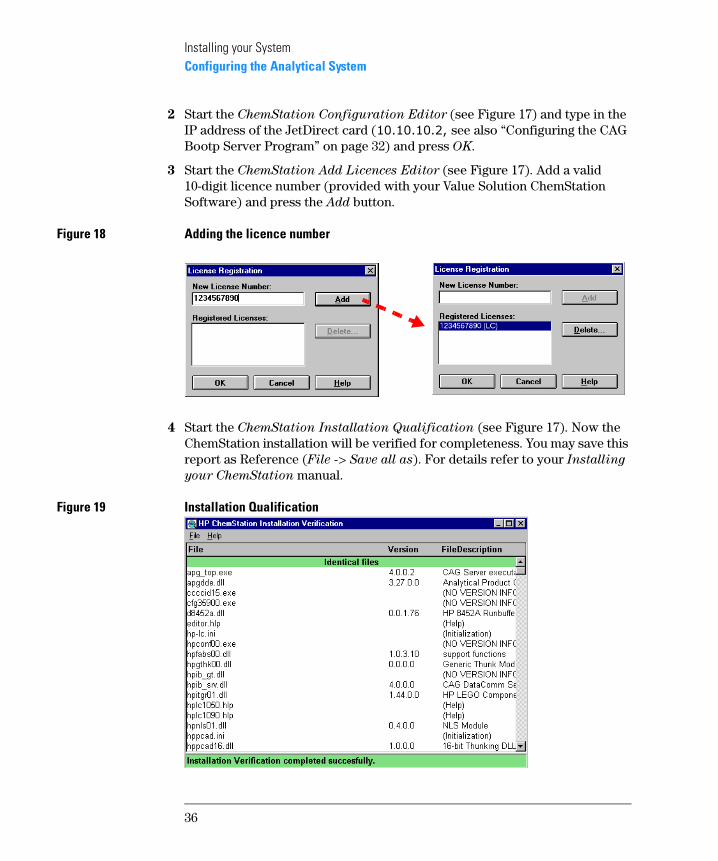
3 Start the ChemStation Add Licences Editor (see Figure 17). Add a valid 10-digit licence number (provided with your Value Solution ChemStation Software) and press the Add button.
Figure 18 Adding the licence number
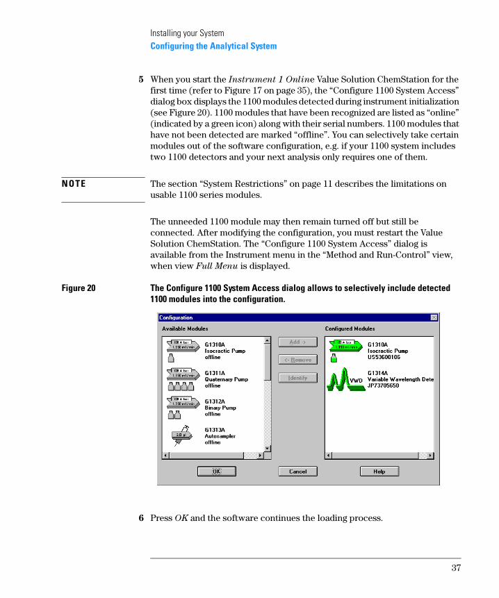
4 Start the ChemStation Installation Qualification (see Figure 17). Now the ChemStation installation will be verified for completeness. You may save this report as Reference (File -> Save all as). For details refer to your Installing
your ChemStation manual.
Figure 19 Installation Qualification
36
Installing your SystemConfiguring the Analytical System
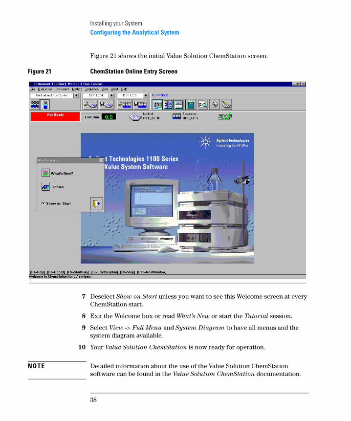
5 When you start the Instrument 1 Online Value Solution ChemStation for the first time (refer to Figure 17 on page 35), the “Configure 1100 System Access” dialog box displays the 1100 modules detected during instrument initialization (see Figure 20). 1100 modules that have been recognized are listed as “online” (indicated by a green icon) along with their serial numbers. 1100 modules that have not been detected are marked “offline”. You can selectively take certain modules out of the software configuration, e.g. if your 1100 system includes two 1100 detectors and your next analysis only requires one of them.
NOTE The section “System Restrictions” on page 11 describes the limitations on usable 1100 series modules.
The unneeded 1100 module may then remain turned off but still be connected. After modifying the configuration, you must restart the Value Solution ChemStation. The “Configure 1100 System Access” dialog is available from the Instrument menu in the “Method and Run-Control” view, when view Full Menu is displayed.
Figure 20 The Configure 1100 System Access dialog allows to selectively include detected 1100 modules into the configuration.
6 Press OK and the software continues the loading process.
37
Installing your SystemConfiguring the Analytical System
Figure 21 shows the initial Value Solution ChemStation screen.
Figure 21 ChemStation Online Entry Screen
7 Deselect Show on Start unless you want to see this Welcome screen at every ChemStation start.
8 Exit the Welcome box or read What’s New or start the Tutorial session.
9 Select View -> Full Menu and System Diagram to have all menus and the system diagram available.
10 Your Value Solution ChemStation is now ready for operation.
NOTE Detailed information about the use of the Value Solution ChemStation software can be found in the Value Solution ChemStation documentation.
38
3
3 Setting up an Analysis
How to analyze the isocratic standard sample using a single injection analysis
Setting up an Analysis
This chapter can be used for three purposes:
• preparing the system,
• to learn the set up of an HPLC analysis and
• to use it as an instrument check to demonstrate that all modules of the system are correctly installed and connected. It is not a test of the instrument performance.
40
Setting up an AnalysisBefore Using the System
Before Using the System
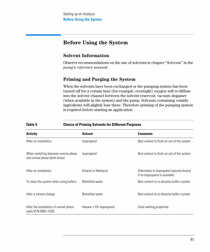
Solvent Information
Observe recommendations on the use of solvents in chapter “Solvents” in the pump’s reference manual.
Priming and Purging the System
When the solvents have been exchanged or the pumping system has been turned off for a certain time (for example, overnight) oxygen will re-diffuse into the solvent channel between the solvent reservoir, vacuum degasser (when available in the system) and the pump. Solvents containing volatile ingredients will slightly lose these. Therefore priming of the pumping system is required before starting an application.
Table 5 Choice of Priming Solvents for Different Purposes
Activity Solvent Comments
After an installation
When switching between reverse phase and normal phase (both times)
Isopropanol
Isopropanol
Best solvent to flush air out of the system
Best solvent to flush air out of the system
After an installation Ethanol or Methanol Alternative to Isopropanol (second choice) if no Isopropanol is available
To clean the system when using buffers
After a solvent change
Bidistilled water
Bidistilled water
Best solvent to re-dissolve buffer crystals
Best solvent to re-dissolve buffer crystals
After the installation of normal phase seals (P/N 0905-1420)
Hexane + 5% Isopropanol Good wetting properties
41
Setting up an AnalysisBefore Using the System
NOTE The pump should never be used for priming empty tubings (never let the pump run dry). Use a syringe to draw enough solvent for completely filling the tubings to the pump inlet before continuing to prime with the pump.
1 Open the purge valve of your pump (by turning it counterclockwise) and set flow rate to 3-5 ml/min.
2 Flush all tubes with at least 30 ml of solvent.
3 Set flow to required value of your application and close the purge valve.
Pump for approximately 10 minutes before starting your application.
42
Setting up an AnalysisRequirements and Conditions
Requirements and Conditions
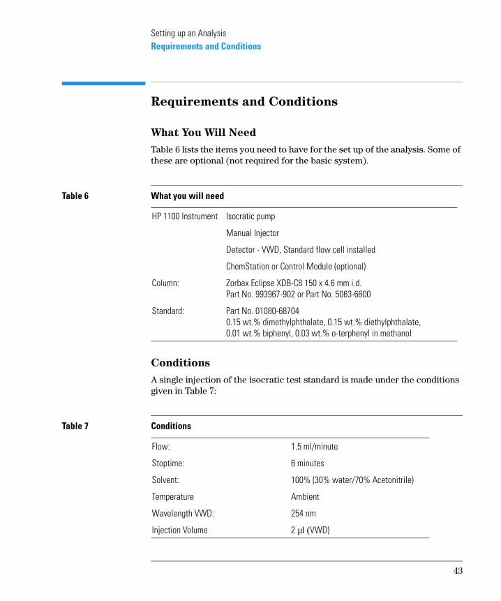
What You Will Need
Table 6 lists the items you need to have for the set up of the analysis. Some of these are optional (not required for the basic system).
Conditions
A single injection of the isocratic test standard is made under the conditions given in Table 7:
Table 6 What you will need
HP 1100 Instrument Isocratic pump
Manual Injector
Detector - VWD, Standard flow cell installed
ChemStation or Control Module (optional)
Column: Zorbax Eclipse XDB-C8 150 x 4.6 mm i.d.Part No. 993967-902 or Part No. 5063-6600
Standard: Part No. 01080-687040.15 wt.% dimethylphthalate, 0.15 wt.% diethylphthalate, 0.01 wt.% biphenyl, 0.03 wt.% o-terphenyl in methanol
Table 7 Conditions
Flow: 1.5 ml/minute
Stoptime: 6 minutes
Solvent: 100% (30% water/70% Acetonitrile)
Temperature Ambient
Wavelength VWD: 254 nm
Injection Volume 2 µl (VWD)
43
Setting up an AnalysisRequirements and Conditions
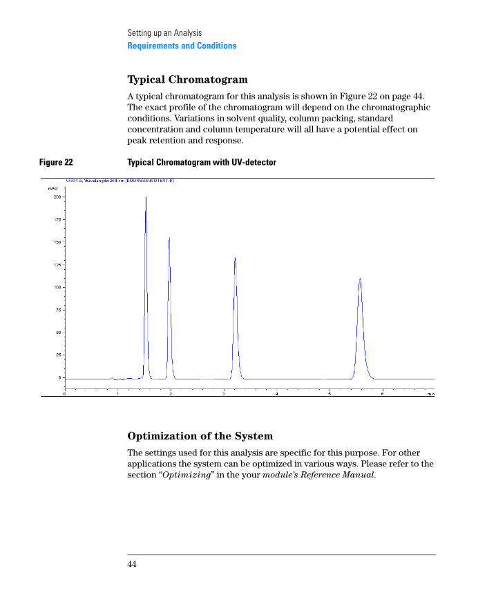
Typical Chromatogram
A typical chromatogram for this analysis is shown in Figure 22 on page 44. The exact profile of the chromatogram will depend on the chromatographic conditions. Variations in solvent quality, column packing, standard concentration and column temperature will all have a potential effect on peak retention and response.
Figure 22 Typical Chromatogram with UV-detector
Optimization of the System
The settings used for this analysis are specific for this purpose. For other applications the system can be optimized in various ways. Please refer to the section “Optimizing” in the your module’s Reference Manual.
44
Setting up an AnalysisPreparing the HPLC System
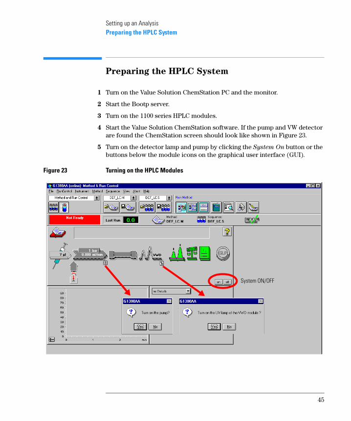
Preparing the HPLC System
1 Turn on the Value Solution ChemStation PC and the monitor.
2 Start the Bootp server.
3 Turn on the 1100 series HPLC modules.
4 Start the Value Solution ChemStation software. If the pump and VW detector are found the ChemStation screen should look like shown in Figure 23.
5 Turn on the detector lamp and pump by clicking the System On button or the buttons below the module icons on the graphical user interface (GUI).
Figure 23 Turning on the HPLC Modules
System ON/OFF
45
Setting up an AnalysisPreparing the HPLC System
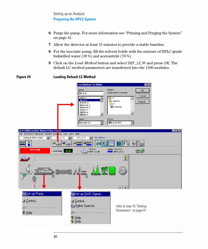
6 Purge the pump. For more information see “Priming and Purging the System” on page 41.
7 Allow the detector at least 15 minutes to provide a stable baseline.
8 For the isocratic pump, fill the solvent bottle with the mixture of HPLC-grade bidistilled water (30 %) and acetonitrile (70 %).
9 Click on the Load Method button and select �� �����and press OK. The default LC method parameters are transferred into the 1100 modules.
Figure 24 Loading Default LC Method
refer to step 10 “Setting Parameters” on page 47
46
Setting up an AnalysisPreparing the HPLC System
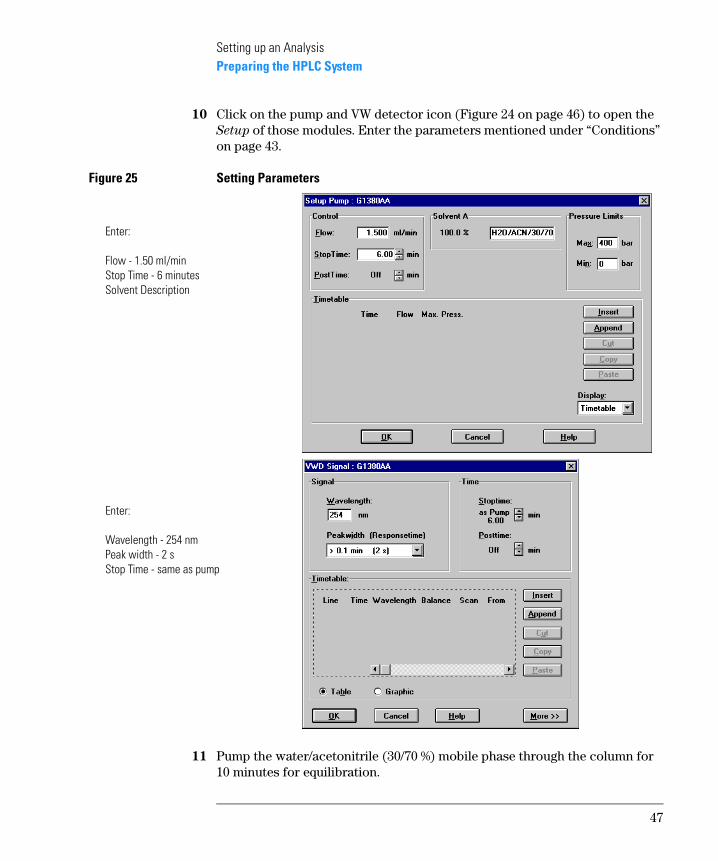
10 Click on the pump and VW detector icon (Figure 24 on page 46) to open the Setup of those modules. Enter the parameters mentioned under “Conditions” on page 43.
Figure 25 Setting Parameters
11 Pump the water/acetonitrile (30/70 %) mobile phase through the column for 10 minutes for equilibration.
Enter:
Flow - 1.50 ml/minStop Time - 6 minutesSolvent Description
Enter:
Wavelength - 254 nmPeak width - 2 sStop Time - same as pump
47
Setting up an AnalysisPreparing the HPLC System
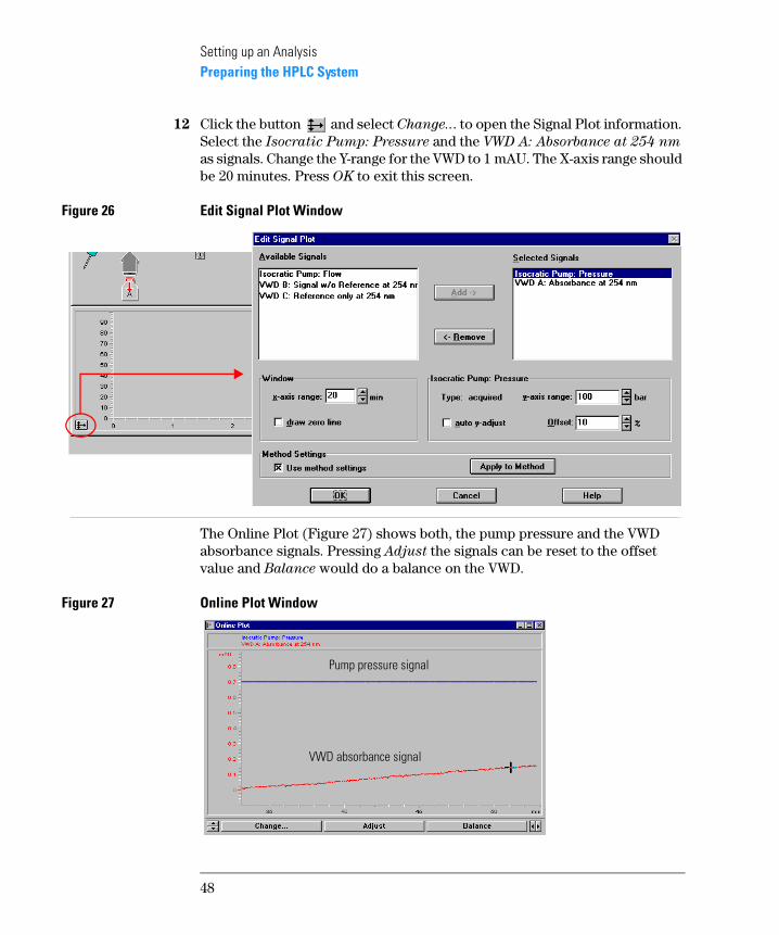
12 Click the button and select Change... to open the Signal Plot information. Select the Isocratic Pump: Pressure and the VWD A: Absorbance at 254 nm as signals. Change the Y-range for the VWD to 1 mAU. The X-axis range should be 20 minutes. Press OK to exit this screen.
Figure 26 Edit Signal Plot Window
The Online Plot (Figure 27) shows both, the pump pressure and the VWD absorbance signals. Pressing Adjust the signals can be reset to the offset value and Balance would do a balance on the VWD.
Figure 27 Online Plot Window
Pump pressure signal
VWD absorbance signal
48
Setting up an AnalysisPreparing the HPLC System
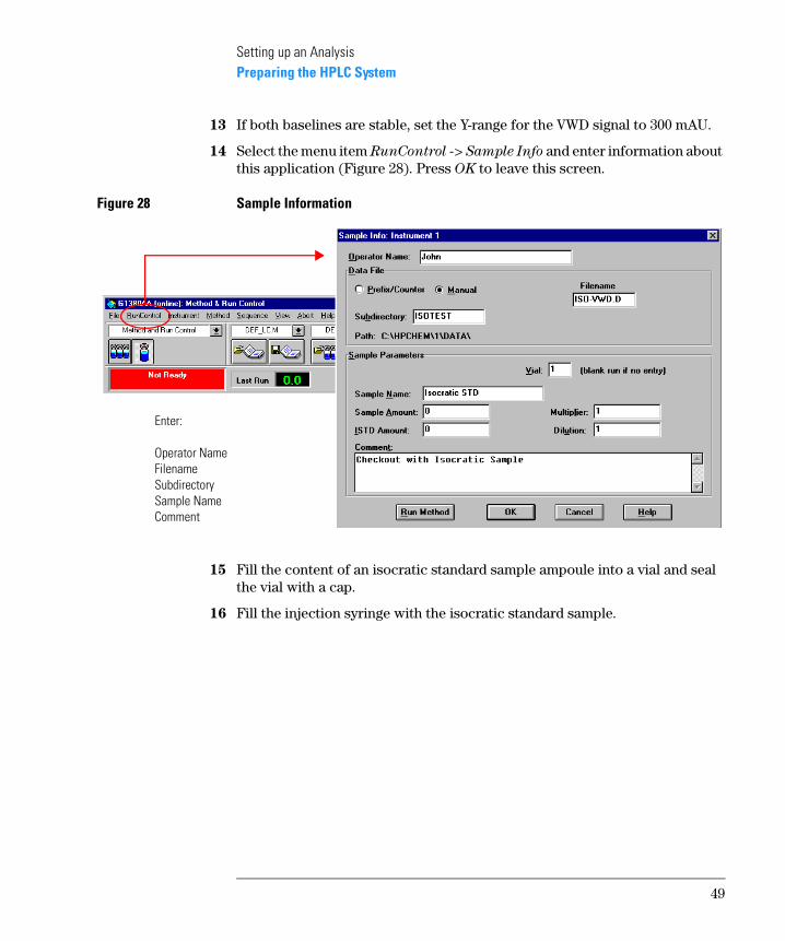
13 If both baselines are stable, set the Y-range for the VWD signal to 300 mAU.
14 Select the menu item RunControl -> Sample Info and enter information about this application (Figure 28). Press OK to leave this screen.
Figure 28 Sample Information
15 Fill the content of an isocratic standard sample ampoule into a vial and seal the vial with a cap.
16 Fill the injection syringe with the isocratic standard sample.
Enter:
Operator NameFilenameSubdirectorySample NameComment
49
Setting up an AnalysisRunning the Sample and Verifying the Results
Running the Sample and Verifying the
Results
1 At the Manual Injector move the handle into the load-position.
2 Take the injection syringe and insert its tip into the Manual Injector port.
3 Inject the sample into the injection port (loop).
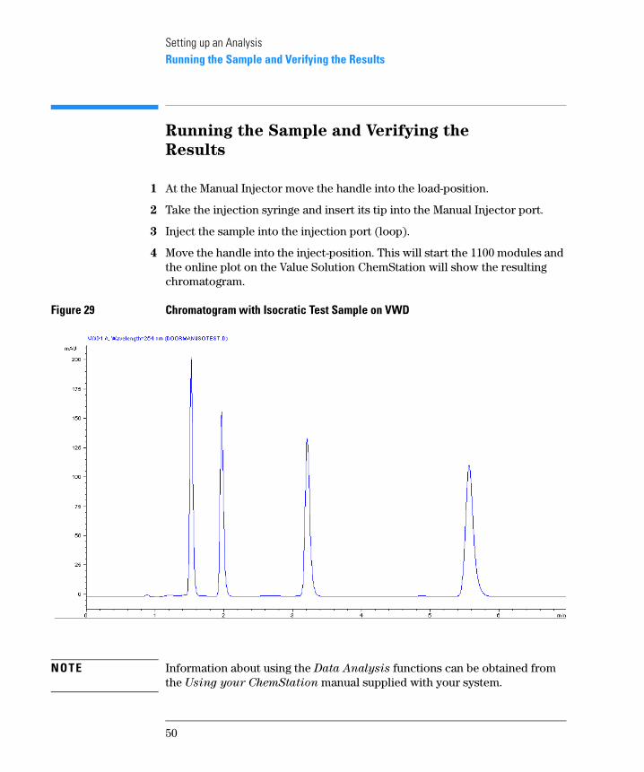
4 Move the handle into the inject-position. This will start the 1100 modules and the online plot on the Value Solution ChemStation will show the resulting chromatogram.
Figure 29 Chromatogram with Isocratic Test Sample on VWD
NOTE Information about using the Data Analysis functions can be obtained from the Using your ChemStation manual supplied with your system.
50
4
4 Troubleshooting your
System
Introduction to the diagnostic features built into your system
Troubleshooting your System
This chapter will introduce you to the diagnostic features built into your system. It is an overview and more details can be found in the system component’s Reference Manuals.
52
Troubleshooting your SystemDiagnostic Functions
Diagnostic Functions
Status Information on the 1100 Modules
LEDs
The 1100 modules provide two LEDs each.
• A green LED is built into the power switch and indicates that the power supply has been turned on. It does not indicate, whether all voltages are present or not.
• A multi-color LED at the top-right of the module, indicates the actual state of the module/system.
RED: indicates an error condition in the module/system (e.g. leak).
YELLOW: indicates a not-ready condition (e.g. lamp is off)
LED OFF: the system is ready (ChemStation is GREEN)
GREEN: the system is in run mode (ChemStation is BLUE)
In case of an error condition, check for corresponding error messages in the system log or instrument error log, see Figure 31 on page 56.
Analog Signals
The isocratic pump and the variable wavelength detector provide an analog output, where module specific analog signals (pump: pressure, pressure ripple; VWD: absorbance signals, board temperature, …) can be selected and plotted to a connected recording device or routed into a data system (via A/D converter).
NOTE For detailed information on error messages, signals and tests refer to the user interface help system and the module’s Reference Manual, section
Diagnostics.
53
Troubleshooting your SystemOnline System Information
Online System Information
Online Messages
The user interface (Value Solution ChemStation or Control Module) provides certain messages (errors or not-ready conditions) online.
Depending on the actual state of the modules/system the color of the system changes.
RED: indicates an error condition in the module/system (e.g. leak).
YELLOW: indicates a not-ready condition (e.g. lamp is off)
LED OFF: the system is ready (ChemStation is GREEN)
BLUE: the system is in run mode
Signals
The isocratic pump and the variable wavelength detector provide module specific signals (e.g. pump: pressure, pressure ripple; VWD: absorbance signals, board temperature, …) that can be monitored online (may vary depending on the user interface in use).
NOTE For detailed information on error messages, signals and tests refer to the user interface help system and the module’s Reference Manual, section
Diagnostics.
54
Troubleshooting your SystemOnline System Information
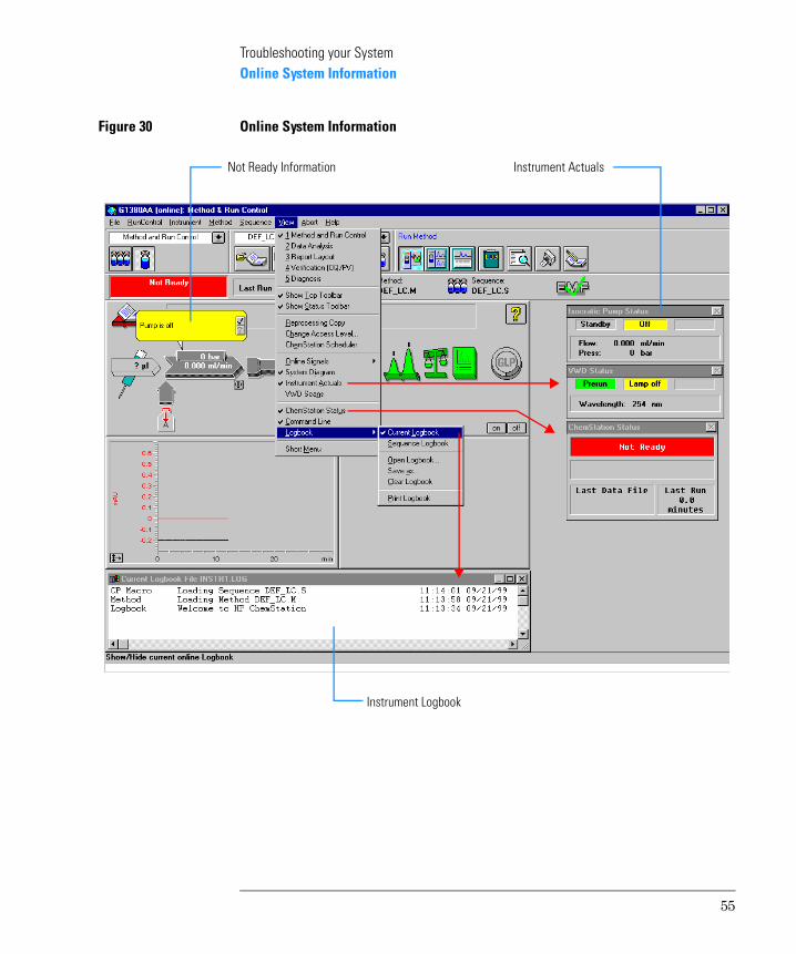
Figure 30 Online System Information
Not Ready Information Instrument Actuals
Instrument Logbook
55
Troubleshooting your SystemInstrument Logbook and Help Information
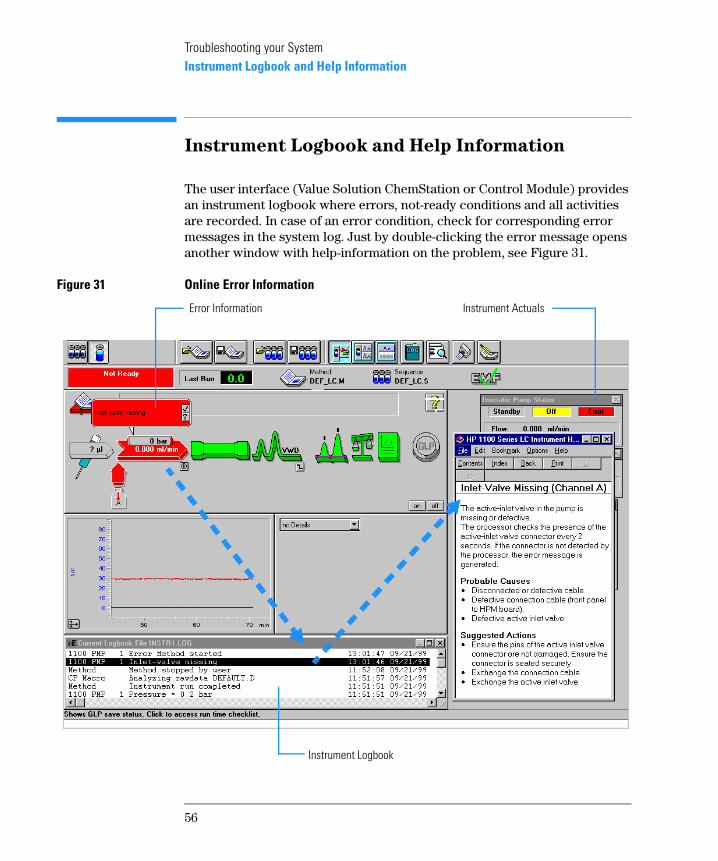
Instrument Logbook and Help Information
The user interface (Value Solution ChemStation or Control Module) provides an instrument logbook where errors, not-ready conditions and all activities are recorded. In case of an error condition, check for corresponding error messages in the system log. Just by double-clicking the error message opens another window with help-information on the problem, see Figure 31.
Figure 31 Online Error Information
Error Information Instrument Actuals
Instrument Logbook
56
Troubleshooting your SystemUsing Module Diagnosis
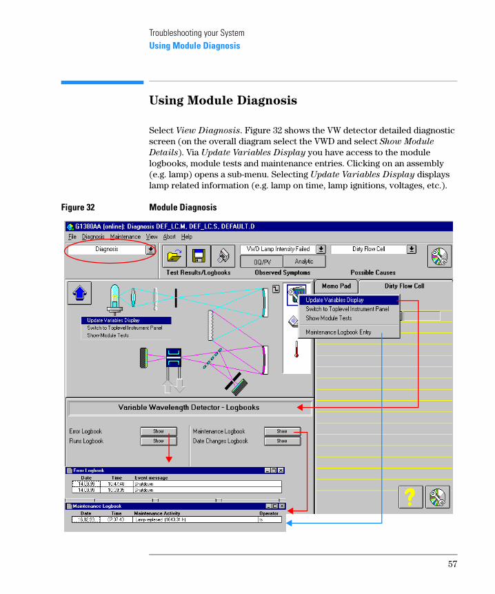
Using Module Diagnosis
Select View Diagnosis. Figure 32 shows the VW detector detailed diagnostic screen (on the overall diagram select the VWD and select Show Module
Details). Via Update Variables Display you have access to the module logbooks, module tests and maintenance entries. Clicking on an assembly (e.g. lamp) opens a sub-menu. Selecting Update Variables Display displays lamp related information (e.g. lamp on time, lamp ignitions, voltages, etc.).
Figure 32 Module Diagnosis
57
Troubleshooting your SystemUsing Module Tests
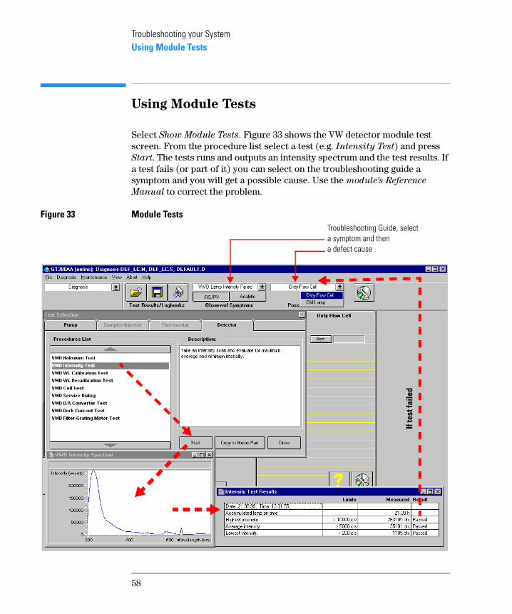
Using Module Tests
Select Show Module Tests. Figure 33 shows the VW detector module test screen. From the procedure list select a test (e.g. Intensity Test) and press Start. The tests runs and outputs an intensity spectrum and the test results. If a test fails (or part of it) you can select on the troubleshooting guide a symptom and you will get a possible cause. Use the module’s Reference
Manual to correct the problem.
Figure 33 Module Tests
If te
st fa
iled
Troubleshooting Guide, select a symptom and then a defect cause
58
Troubleshooting your SystemProblems during the Installation
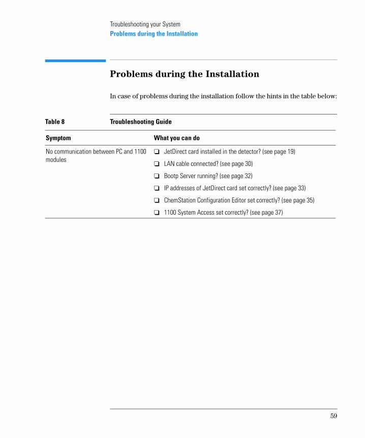
Problems during the Installation
In case of problems during the installation follow the hints in the table below:
Table 8 Troubleshooting Guide
Symptom What you can do
No communication between PC and 1100 modules
❏ JetDirect card installed in the detector? (see page 19)
❏ LAN cable connected? (see page 30)
❏ Bootp Server running? (see page 32)
❏ IP addresses of JetDirect card set correctly? (see page 33)
❏ ChemStation Configuration Editor set correctly? (see page 35)
❏ 1100 System Access set correctly? (see page 37)
59

Troubleshooting your SystemProblems during the Installation
60
5
5 Repair and Maintenance
What you should know about your system
Repair and MaintenanceRepair and Parts Information for the 1100 series HPLC Modules
Repair and Parts Information for the 1100
series HPLC Modules
There is no specific repair and parts information other than that available in the Reference Manuals of the 1100 series HPLC modules, sections “Repairing the …” and “Identifying Parts and Materials”.
62
Repair and MaintenanceFirmware Update on 1100 Modules
Firmware Update on 1100 Modules
The installation of new firmware is required
• if a new version solves problems of the currently installed version.
• if the version of firmware on the new main board after an exchange of the board is older than the one previously installed.
To upgrade the module’s firmware follow the procedures and instructions given on the internet addresses:
To download and install always the newest available version of firmware on
http://www.agilent.com section Service&Support - Chemical Analysis - Technical Support
http://www.chem.agilent.com section Technical Support
63
Repair and MaintenanceDeinstallation and Reinstallation of the ChemStation
Deinstallation and Reinstallation of the
ChemStation
The reinstallation of the Value Solution ChemStation software may be required in case of other problems during normal operation.
The steps below will give a quick overview on the actions:
1 Backup all the important data, specific methods and sequences located under \HPCHEM\1\....
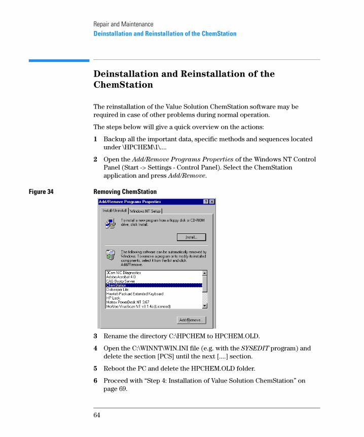
2 Open the Add/Remove Programs Properties of the Windows NT Control Panel (Start -> Settings - Control Panel). Select the ChemStation application and press Add/Remove.
Figure 34 Removing ChemStation
3 Rename the directory C:\HPCHEM to HPCHEM.OLD.
4 Open the C:\WINNT\WIN.INI file (e.g. with the SYSEDIT program) and delete the section [PCS] until the next [....] section.
5 Reboot the PC and delete the HPCHEM.OLD folder.
6 Proceed with “Step 4: Installation of Value Solution ChemStation” on page 69.
64
Repair and MaintenanceRecovering from an Operating System Crash
Recovering from an Operating System
Crash
The re-installation of the complete operating system is required after a system crash or in case of other problems during normal operation.
WARNING The procedure below will overwrite the complete system. This means
all existing data on the PC will be lost. Any sensitive data must be
backed on a different media prior to this process.
What you need
❏ Recovery CD
❏ Password for NT
❏ Value Solution ChemStation software CD
❏ Licence number
Process steps
1 Installation of Windows NT
2 Installation of TCP/IP protocol
3 Re-installation of Windows NT service pack
4 Installation of Value Solution ChemStation software
5 Installation of Bootp Server program
6 Configuring the CAG Bootp Server program
Step 1: Installation of Windows NT
1 Insert the recovery CD into the CD-ROM drive.
2 Turn on the PC.
3 Press Enter to start the installation of the Windows NT operating systems.
65
Repair and MaintenanceRecovering from an Operating System Crash
4 The PC will reboot and stop at the Login Information screen. The pre-configured user is ‘Administrator’ and requires the password provided with your PC.
5 Then press OK.
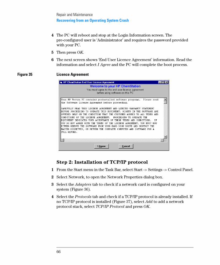
6 The next screen shows ‘End User Licence Agreement’ information. Read the information and select I Agree and the PC will complete the boot process.
Figure 35 Licence Agreement
Step 2: Installation of TCP/IP protocol
1 From the Start menu in the Task Bar, select Start -> Settings -> Control Panel.
2 Select Network, to open the Network Properties dialog box.
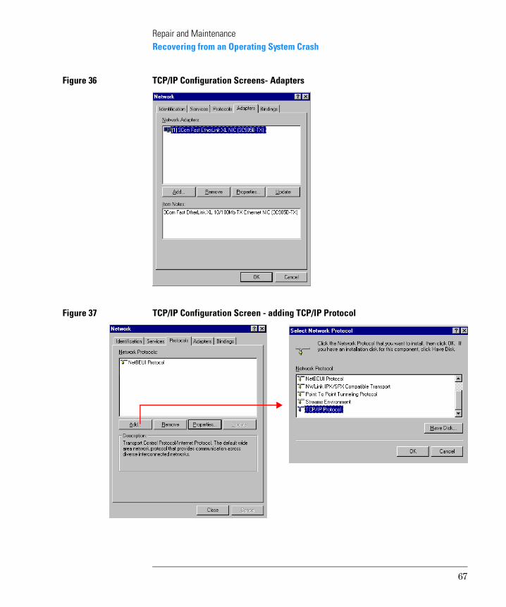
3 Select the Adapters tab to check if a network card is configured on your system (Figure 36).
4 Select the Protocols tab and check if a TCP/IP protocol is already installed. If no TCP/IP protocol is installed (Figure 37), select Add to add a network protocol stack, select TCP/IP Protocol and press OK.
66
Repair and MaintenanceRecovering from an Operating System Crash
Figure 36 TCP/IP Configuration Screens- Adapters
Figure 37 TCP/IP Configuration Screen - adding TCP/IP Protocol
67
Repair and MaintenanceRecovering from an Operating System Crash
5 Select No to the usage of DHCP and use C:\I386 as the location of your Windows NT 4.0 installation files on your hard disk.
After the file copying is finished, select the Bindings tab, to allow NT to associate the TCP/IP protocol with your installed network adapter.
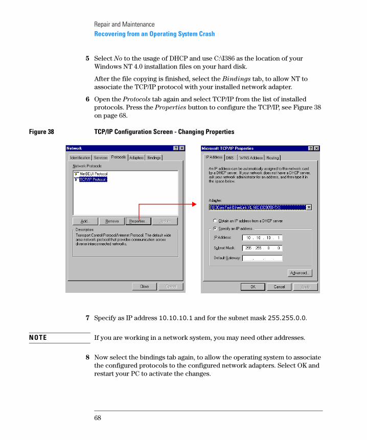
6 Open the Protocols tab again and select TCP/IP from the list of installed protocols. Press the Properties button to configure the TCP/IP, see Figure 38 on page 68.
Figure 38 TCP/IP Configuration Screen - Changing Properties
7 Specify as IP address ���������� and for the subnet mask �����������.
NOTE If you are working in a network system, you may need other addresses.
8 Now select the bindings tab again, to allow the operating system to associate the configured protocols to the configured network adapters. Select OK and restart your PC to activate the changes.
68
Repair and MaintenanceRecovering from an Operating System Crash
Step 3: Re-installation of Windows NT Service Pack
NOTE After the PC has been re-started it is necessary to re-install the Windows NT Service Pack to update older file versions.
1 Run the SP4I386.EXE from directory C:\I386\SP4.
2 Restart your PC to activate the changes.
Step 4: Installation of Value Solution ChemStation
1 Insert your Value Solution ChemStation software CD into the CD-ROM drive.
2 Select a path, usually C:\HPCHEM.
3 Choose a program folder, usually ChemStations.
4 Add the licence number of your Value Solution ChemStation software, see “Adding the licence number” on page 36.
5 Add the IP address of the JetDirect card, located in the VW detector. Type in ����������, see “ChemStation Program Folder” on page 35.
6 At the end of the installation you are asked to reboot to make the changes active.
Step 5: Installation of the Bootp Server Program
1 Insert your Value Solution ChemStation software CD into the CD-ROM drive.
2 From the Windows Start menu in the Task Bar, select Start -> Run and browse for E:\Bootp\Setup.exe. Select it and run it. The Bootp Server program will be installed now.
Step 6: Configuring the CAG Bootp Server Program
NOTE Assure that the VW detector (with JetDirect card installed and connected to the PC) is powered off.
The CAG Bootp Server program is placed in the start-up group and automatically is started during the boot process of the PC. It’s minimized and located in the task bar.
69
Repair and MaintenanceRecovering from an Operating System Crash
1 Open the Bootp Server window by clicking on it in the task bar.
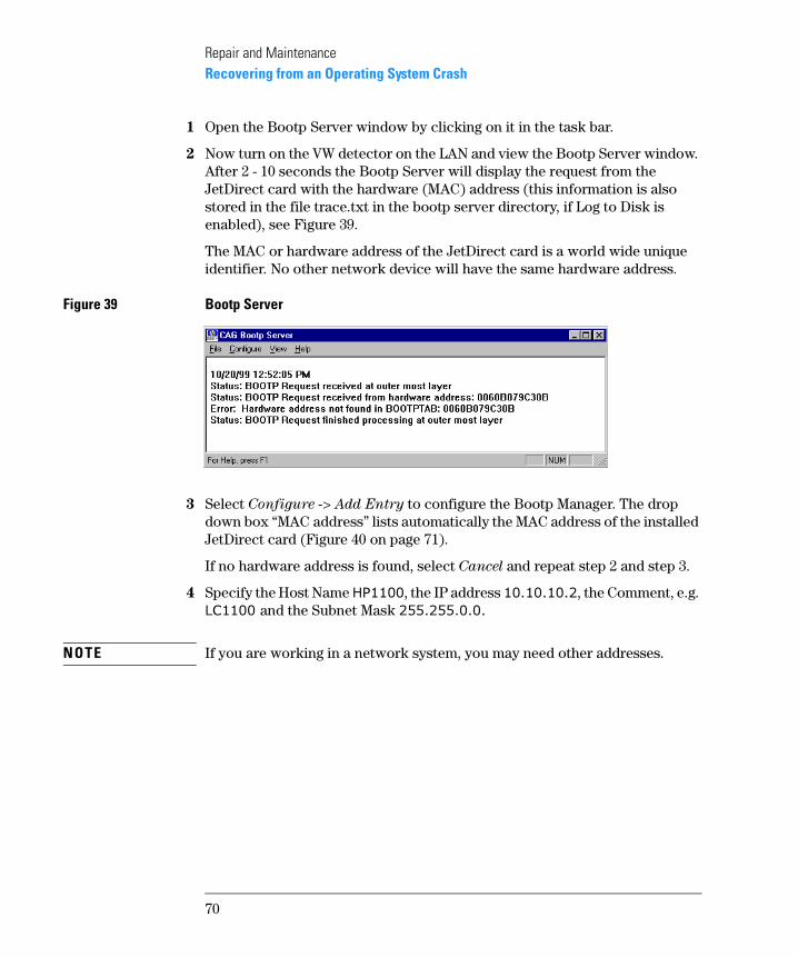
2 Now turn on the VW detector on the LAN and view the Bootp Server window. After 2 - 10 seconds the Bootp Server will display the request from the JetDirect card with the hardware (MAC) address (this information is also stored in the file trace.txt in the bootp server directory, if Log to Disk is enabled), see Figure 39.
The MAC or hardware address of the JetDirect card is a world wide unique identifier. No other network device will have the same hardware address.
Figure 39 Bootp Server
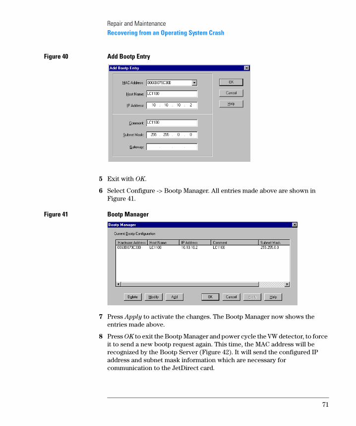
3 Select Configure -> Add Entry to configure the Bootp Manager. The drop down box “MAC address” lists automatically the MAC address of the installed JetDirect card (Figure 40 on page 71).
If no hardware address is found, select Cancel and repeat step 2 and step 3.
4 Specify the Host Name ������, the IP address ����������, the Comment, e.g. �������and the Subnet Mask �������������
NOTE If you are working in a network system, you may need other addresses.
70
Repair and MaintenanceRecovering from an Operating System Crash
Figure 40 Add Bootp Entry
5 Exit with OK.
6 Select Configure -> Bootp Manager. All entries made above are shown in Figure 41.
Figure 41 Bootp Manager
7 Press Apply to activate the changes. The Bootp Manager now shows the entries made above.
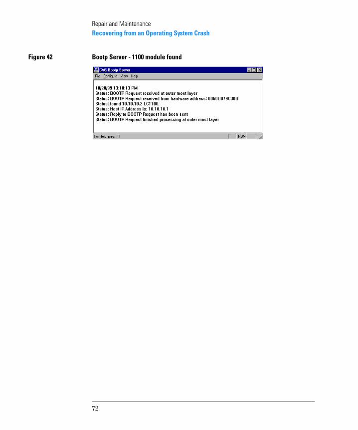
8 Press OK to exit the Bootp Manager and power cycle the VW detector, to force it to send a new bootp request again. This time, the MAC address will be recognized by the Bootp Server (Figure 42). It will send the configured IP address and subnet mask information which are necessary for communication to the JetDirect card.
71
Repair and MaintenanceRecovering from an Operating System Crash
Figure 42 Bootp Server - 1100 module found
72
Index
Numerics1100 Series
controller area network (CAN), 35
Aadding
the licence number, 36analog signals, 53, 54APG-remote, 23
Bbooting the PC, 31
CCAN
1100 Series, 35connecting, 23
capillary connections, 24configuration editor, 36controller area network
1100 Series, 35
Ddelivery checklist, 18diagnose
a module, 57dimensions, 14documentation, 16
Eerrors
indicator, 53logbooks, 53, 54online messages, 54
Ffirmware update, 63flow connections, 24
Hhardware address
JetDirect card, 32, 70humidity, 14
Iinstallation
delivery checklist, 18of flow connections, 28
unpacking, 18installing
1100 modules, 21ChemStation hardware, 30JetDirect card, 19manual injector, 21
JJetDirect card
hardware address, 32, 70installation, 19
Llamp ignitions
logbook, 57lamp on time
logbook, 57LAN
installing communication, 32leak channel, 25leak drainage, 25leaks, 24LED, 53legal information, 15licence number
adding, 36line voltage and frequency, 14logbook
lamp ignitions, 57lamp on time, 57
logbooks, 53, 54login information, 31, 66
Mmaintenance
entries, 57maintenance, repair and parts, 15manuals, 16module diagnose section, 57module tests, 57, 58
NNT login information, 31, 66
Oonline messages, 54operation temperature, 14optimization
of the system, 44
Pparts, 15performance specifications, 15physical specifications, 14
humidity, 14line voltage and frequency, 14operation temperature, 14power consumption, 14weight and dimensions, 14
position-sensor cable, 23power consumption, 14problems during installation, 59purging the pump, 41
Rre-installation
ChemStation, 64repair, 15
Ssafety information
standards, 14site requirements
bench space, 13environment, 13power considerations, 12power cords, 12
snap fasteners, 26specifications
performance, 15start cable, 23status indicator, 53
Ttest
failed, 58module, 57, 58
troubleshootinganalog signals, 53, 54guide, 58symptom and cause, 58
troubleshooting guide, 59
Uunpacking, 18user documentation, 16
73
Index
Wwarranty and legal, 15weight, 14
74

In This Book
This manual contains technical reference information about the Agilent 1100 Series HPLC value system. The manual describes the following:
• system overview, specifications and limitations,
• installing the system,
• setting up an analysis,
• diagnostics and troubleshooting, and
• repairing and maintenance.