a. system overview terminal crimping tools · 4111km. 0.0:-. . panduit terminal crimping tools are...
TRANSCRIPT

4111km. .0.0:-.
Panduit terminal crimping tools are available in an assortment of styles to meet a variety of
installation needs. The installer can control the crimp with the plier type hand operated crimping tool.
Hand operated Contour Crimp™ Controlled Cycle Crimping Tools feature ergonomically designed
cushioned grips with low handle effort. Panduit terminal crimping tools are designed for use with
Panduit terminals, providing the right solution for your termination needs.
For technical assistance in the U.S., call 866-405-6654 (outside the U.S., see inside back cover for directory)
ELECTRICAL SOLUTIONS
D1.79
TERMINAL CRIMPING TOOLSPanduit offers a wide assortment of tools to provide solutions for installing terminals,
disconnects, splices, ferrules and lugs. Panduit installation tools provide quality performance and ease of
installation at the lowest installed cost.The long-term reliability of Panduit installation tools provides the
highest level of service to meet customer requirements.
• Ergonomic design to minimize operator effort
• Features crimping tools with a controlled cyclemechanism ensuring repeat reliability in every crimp
• Superior locator ensures proper location of theterminal barrel or insulated disconnect in the crimp pocket
• Battery powered, hydraulic tools with fingertipoperation are available to meet a variety ofinstallation needs
• UL Listed and CSA Certified tooling/productcombinations, as noted
B2.Cable
Accessories
C1.Wiring
Duct
C3.Abrasion
Protection
C4.Cable
Management
D1.Terminals
D2.Power
Connectors
E1.LabelingSystems
E2.Labels
E3.Pre-Printed & Write-On
Markers
F.Index
B3.StainlessSteel Ties
C2.Surface
Raceway
E5.Lockout/Tagout
& SafetySolutions
B1.Cable Ties
A.System
Overview
D3.GroundingConnectors
E4.Permanent
Identification

PV14-8R-C PRESSURE TERMINAL CONNECT OR Rw TEM..,
OR SOL I. 010 Cu *RE [Mr vlooriol
WitE RIOS. CNA l(bo RATE OF INIOL NAT MC
°F0V RAN NW 'COW AM =
3C1,O. FrOUOS LANRE3
`3CAC-5353001-155, CAS03 Mc&
• oSE win At INC NAA IlliAC.RARLEROORNW • -0)
,
_ 1.• it,
ELECTRICAL SOLUTIONS
Order number of pieces required, in multiples of Standard Package Quantity. Prime items appear in BOLD.D1.80
B2.Cable
Accessories
C1.Wiring
Duct
C3.Abrasion
Protection
C4.Cable
Management
D1.Terminals
D2.Power
Connectors
E1.LabelingSystems
E2.Labels
E3.Pre-Printed & Write-On
Markers
F.Index
B3.StainlessSteel Ties
C2.Surface
Raceway
E5.Lockout/Tagout
& SafetySolutions
B1.Cable Ties
A.System
Overview
D3.GroundingConnectors
E4.Permanent
Identification
Crimping Guidelines for Panduit® Pan-Term ® Terminals, Disconnects,Splices and Wire Joints
5. Perform the electrical crimp for the plier type toolInsulated Terminals and DisconnectsA. Locate terminal in appropriate size color-coded crimp die
pocket with tool centered on insulation sleeve.(See Note 1, page D1.82)
B. Rotate terminal so tongue is level with crimp die.
C. Insert properly stripped wire into terminal until a minimum of1/32'' of wire extends beyond the terminal barrel.
D. Squeeze tool handles firmly to perform the electrical crimp.(See Note 2, page D1.82)
E. Provide second crimp on the flared portion of the insulation housing toclose the insulation as shown. Caution: When using plier type crimpingtools, do not squeeze as firmly as you did for the electrical crimp.(See Note 3, page D1.82)
Step A Step B Steps C and D
Step E Complete Crimp
3. Select the proper crimp tool to be used• Use crimping tools that provide a UL Listed and/or CSA Certified electrical termination, to assure a safe and
reliable connection
• Panduit terminals are UL Listed and CSA Certified when crimped with Panduit plier type crimping tool or with the preferredContour Crimp™ Controlled Cycle Crimping Tool specified on the packaging label
1. Select the proper Panduit terminal for the application and wire size used• Ring terminals are used for high vibration and grounding applications
• Fork terminals are used for static (non-vibration) applications
• Disconnects are used for applications that require quick connection of wires without the use of tools
• Splices and wire joints are used to join wires together
2. Strip wire to the proper length as specified on:• Panduit product packaging label
• Packaging instructions included with the Panduit product
• Or if no packaging instructions are available, plan your strip length so that 1/32'' of wire can be seen protruding throughthe tongue end of the terminal barrel
4. Select the proper crimp pocket for the terminals and wire size you are using• Panduit crimping tools simplify this process with color-coded crimp pockets. The yellow, blue, and red pockets are
specifically designed for the industry standard barrel sizes, each with a specific color code.
Plier TypeCrimping Tool
Contour Crimp™
Controlled CycleCrimping Tool

For technical assistance in the U.S., call 866-405-6654 (outside the U.S., see inside back cover for directory)
ELECTRICAL SOLUTIONS
D1.81
B2.Cable
Accessories
C1.Wiring
Duct
C3.Abrasion
Protection
C4.Cable
Management
D1.Terminals
D2.Power
Connectors
E1.LabelingSystems
E2.Labels
E3.Pre-Printed & Write-On
Markers
F.Index
B3.StainlessSteel Ties
C2.Surface
Raceway
E5.Lockout/Tagout
& SafetySolutions
B1.Cable Ties
A.System
Overview
D3.GroundingConnectors
E4.Permanent
Identification
Crimping Guidelines for Panduit ® Pan-Term ® Terminals, Disconnects,Splices and Wire Joints (continued)
Non-Insulated Terminals and DisconnectsA. Locate terminal in appropriate wire gauge crimp die
pocket with indenter centered on barrel seam.
B. Rotate terminal so tongue is level with crimp die.
C. Insert properly stripped wire (based on recommendationson package label) into terminal until a minimum of 1/32'' of wire extends beyond the terminal barrel.
D. Squeeze tool handles firmly to perform the electricalcrimp. (See Note 2, page D1.82)
Insulated and Non-Insulated Parallel SplicesA. Locate parallel splice in appropriate wire gauge crimp die
pocket and position tool on the center of the splice.
B. Rotate terminal so tongue is level with crimp die.
C. Insert properly stripped wire (based on recommendationson package label) into each end of the parallel splice.
D. Squeeze tool handles firmly. (See Note 2, page D1.82)
E. An insulation crimp is not required on an insulatedparallel splice.
Step A Step B Steps C and D
Complete Crimp
Steps A and B Steps C and D Complete Crimp
Insulated and Non-Insulated Butt SplicesA. Locate butt splice in appropriate color-coded crimp die
pocket and position crimp halfway between the wire stop(center of splice) and the end of the insulation crimp area.(See Note 4, page D1.82)
B. Insert properly stripped wire (based on recommendationson package label) into one end of butt splice.
C. Squeeze tool handles firmly to perform the electricalcrimp (See Note 2, page D1.82)
D. Provide second crimp on the flared portion of theinsulation housing to close the insulation. Caution: Whenusing plier type crimping tools, do not squeeze as firmly asyou did for the electrical crimp. (See Note 3, page D1.82)
E. Repeat steps 1 – 4 for opposite end of butt splice.(See Note 3, page D1.82)
Steps A and B Step C Steps D and E
Complete Crimp

• ; ! 0"4. • 41
041111
. • t
--11*. • •
ELECTRICAL SOLUTIONS
Order number of pieces required, in multiples of Standard Package Quantity. Prime items appear in BOLD.D1.82
B2.Cable
Accessories
C1.Wiring
Duct
C3.Abrasion
Protection
C4.Cable
Management
D1.Terminals
D2.Power
Connectors
E1.LabelingSystems
E2.Labels
E3.Pre-Printed & Write-On
Markers
F.Index
B3.StainlessSteel Ties
C2.Surface
Raceway
E5.Lockout/Tagout
& SafetySolutions
B1.Cable Ties
A.System
Overview
D3.GroundingConnectors
E4.Permanent
Identification
Crimping Guidelines for Panduit ® Pan-Term ® Terminals, Disconnects,Splices and Wire Joints (continued)
Insulated and Non-Insulated Wire JointsA. Properly strip wires per manufacturer’s
recommendations on product package label.
B. Twist stripped wire ends together and insert wires intowire joint.
C. Locate wire joint in appropriate wire gauge crimp diepocket and position crimp in the center of the metal insert.
D. Squeeze tool handles firmly to perform the electricalcrimp. (See Note 2 below)
Note: An insulation crimp is not required on an insulatedwire joint.
NOTES for Crimping with the Preferred Hand Operated Controlled Cycle Crimping Tools:1. Panduit controlled cycle crimping tools properly locate rings, forks, and barrel insulated disconnects, pins, and blades. No
further positioning is required.
2. When using the preferred controlled cycle tool, once a crimp has been started, the ratchet device of controlled cycletools will not release until the crimp is complete, independent of operator expertise.
3. Controlled cycle tools provide the electrical crimp and the insulation closure in a single cycle of the tool.
4. When using controlled cycle tooling, insulated butt splices must be inserted from the back of the tool to ensure that theelectrical and insulation closure crimp pockets are properly aligned with the splice.
Steps A and B Steps C and D Complete Crimp
5. Perform the electrical crimp using the preferredcontrolled cycle tool
A. Make sure the terminal barrel is centered correctly in theright die pocket by using the product locator on thebackside of the tool.
B. Determine the correct die pocket to use based on the colorcode of the terminal.
C. Squeeze the handles of the tool until one click is heard;this click indicates the terminal is now held in placesecurely to insert the wire.
D. Insert the wire and complete cycle to perform the electricaland insulation crimp simultaneously.
E. Crimp is complete.
Step A Step B Step C
Complete Crimp
6. Inspect the crimpNote: If your crimp looks like any of the examples shown
below, cut off the terminal and re-crimp. These crimpswould provide a poor connection!
Bent Back Strands Over Crimp Rotated Crimp
Step D

iihNDUIT®
For technical assistance in the U.S., call 866-405-6654 (outside the U.S., see inside back cover for directory)
ELECTRICAL SOLUTIONS
D1.83
B2.Cable
Accessories
C1.Wiring
Duct
C3.Abrasion
Protection
C4.Cable
Management
D1.Terminals
D2.Power
Connectors
E1.LabelingSystems
E2.Labels
E3.Pre-Printed & Write-On
Markers
F.Index
B3.StainlessSteel Ties
C2.Surface
Raceway
E5.Lockout/Tagout
& SafetySolutions
B1.Cable Ties
A.System
Overview
D3.GroundingConnectors
E4.Permanent
Identification
Hand Operated Plier Type Tools
• Installer controlled crimp
• Available with wire stripping and cutting features
• Plier type crimp for #22 – 10 AWG insulated and non-insulated terminal products
CT-100A
CT-160
CT-260
Wire and Cable Stripping Tools
• Strips and cuts #20 – 10 AWG wire
• Lightweight and durable for comfortable long use
• Rust resistant coating included to improve durability of tool
CT-200
Part NumberWire Range
(O.D.) Part Description
Std.Pkg.Qty.
CST115 #20 – 10 AWG Plier nose wire stripper. 1
Part Number Part Description
Std.Pkg.Qty.
CT-260 Crimps most Panduit #22 – 10 AWG insulated and non-insulated terminals. Forgedsteel tool. Cuts wire.
1
CT-200 Forged steel tool. Crimps most Panduit #22 – 10 AWG non-insulated terminals,disconnects and splices. Cuts wire.
1
CT-160 Crimps most Panduit #22 – 10 AWG insulated and non-insulated terminalsdisconnects and splices. Cuts three U.S. and three metric screw sizes. Cuts andstrips wire. Has insulation closure pocket.
1
CT-100A Crimps most Panduit #22 – 10 AWG insulated and non-insulated terminals,disconnects, and splices. Cuts #4, #6, #8 and #10 screw sizes. Cuts and strips wire.Excellent all-around application tool of heat treated finished steel with comfortablecushioned plastic grip handles.
1

ELECTRICAL SOLUTIONS
Order number of pieces required, in multiples of Standard Package Quantity. Prime items appear in BOLD.D1.84
B2.Cable
Accessories
C1.Wiring
Duct
C3.Abrasion
Protection
C4.Cable
Management
D1.Terminals
D2.Power
Connectors
E1.LabelingSystems
E2.Labels
E3.Pre-Printed & Write-On
Markers
F.Index
B3.StainlessSteel Ties
C2.Surface
Raceway
E5.Lockout/Tagout
& SafetySolutions
B1.Cable Ties
A.System
Overview
D3.GroundingConnectors
E4.Permanent
Identification
Contour Crimp™ Controlled Cycle Tools
• Controlled cycle mechanism assures high quality, consistentterminations
• Ergonomic tool design assures operator comfort, safety, andperformance
• Polypropylene handles provide chemical resistance and acushioned, non-slip grip
Part Number Part Description
Std.Pkg.Qty.
CT-1525 Crimps Panduit #26 – 22 AWG insulated terminals and splices, #22 – 10 AWG fullyinsulated disconnects and insulated parallel splices. Crimps Panduit#22 – 14 AWG barrel insulated disconnects.
1
CT-1550 Crimps most Pan-Term ® #22 – 10 AWG nylon and vinyl insulated terminals,splices, and disconnects. The CT-1550 has the red/blue pocket closest to the pivotwhich provides a reduced crimp effort for those who make red/blue terminations.
1
CT-1551 Crimps most Pan-Term ® #22 – 10 AWG nylon and vinyl insulated terminals,splices, and disconnects. The CT-1551 has the yellow pocket closest to the pivotwhich provides a reduced crimp effort for those who make yellow terminations.
1
CT-1570 Crimps most Pan-Term ® #22 – 10 AWG and .5 – 6.0mm² non-insulated terminalsand disconnects. Crimps Panduit #22 – 10 AWG and .5 – 6.0mm² non-insulatedsplices and #10 AWG compression lugs.
1
CT-1700 Crimps Panduit #8 – 2 AWG non-insulated tubular terminals (S series), #8 – 1 AWGcopper code conductor lugs and splices, #8 – 2 AWG copper flex conductor lugs,#6 – 4 AWG dual rated aluminum lugs and splices and CTAPF10-16 to CTAPF3-12copper taps. Includes 5-position, color coded rotating die.
1
CT-1701 Crimps Panduit #10 – 2 AWG non-insulated large gauge ring terminals (P series),#12 – 4 AWG non-insulated heavy duty ring terminals (P series), and #14 – 10 AWGcopper code conductor lugs. Includes 5-position, rotating die.
1
CT-1014 Crimps Panduit #22 – 14 AWG loose piece Disco-Lok ™ Disconnects. 1
CT-1015 Crimps Panduit #22 – 14 AWG loose piece Supra-Grip ™ Disconnects. 1
CT-1525
CT-1551
CT-1570
CT-1700
CT-1550
CT-1701
CT-1014
CT-1015
For technical assistance in the U.S., call 866-405-6654 (outside the U.S., see inside back cover for directory)
ELECTRICAL SOLUTIONS
D1.85
B2.Cable
Accessories
C1.Wiring
Duct
C3.Abrasion
Protection
C4.Cable
Management
D1.Terminals
D2.Power
Connectors
E1.LabelingSystems
E2.Labels
E3.Pre-Printed & Write-On
Markers
F.Index
B3.StainlessSteel Ties
C2.Surface
Raceway
E5.Lockout/Tagout
& SafetySolutions
B1.Cable Ties
A.System
Overview
D3.GroundingConnectors
E4.Permanent
Identification
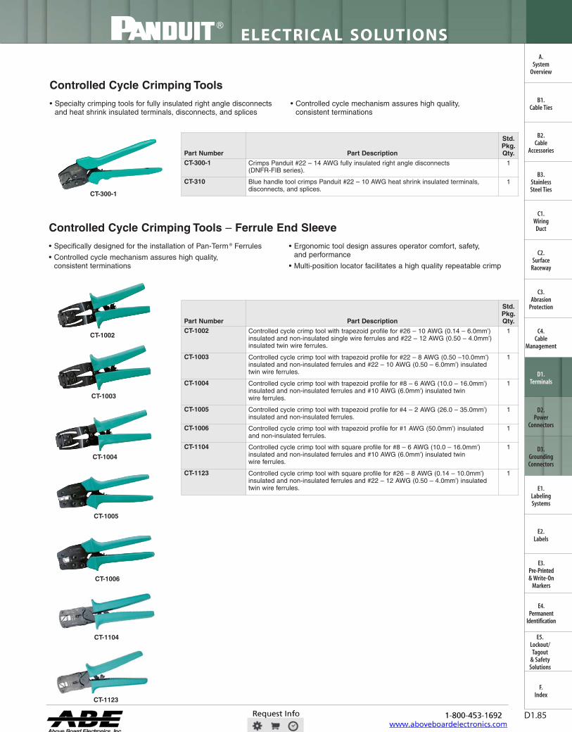
Controlled Cycle Crimping Tools
• Specialty crimping tools for fully insulated right angle disconnectsand heat shrink insulated terminals, disconnects, and splices
• Controlled cycle mechanism assures high quality,consistent terminations
Part Number Part Description
Std.Pkg.Qty.
CT-300-1 Crimps Panduit #22 – 14 AWG fully insulated right angle disconnects(DNFR-FIB series).
1
CT-310 Blue handle tool crimps Panduit #22 – 10 AWG heat shrink insulated terminals,disconnects, and splices.
1
Controlled Cycle Crimping Tools – Ferrule End Sleeve
• Specifically designed for the installation of Pan-Term ® Ferrules
• Controlled cycle mechanism assures high quality,consistent terminations
• Ergonomic tool design assures operator comfort, safety,and performance
• Multi-position locator facilitates a high quality repeatable crimp
CT-1002
CT-300-1
CT-1003
CT-1004
CT-1005
CT-1006
CT-1123
Part Number Part Description
Std.Pkg.Qty.
CT-1002 Controlled cycle crimp tool with trapezoid profile for #26 – 10 AWG (0.14 – 6.0mm²)insulated and non-insulated single wire ferrules and #22 – 12 AWG (0.50 – 4.0mm²)insulated twin wire ferrules.
1
CT-1003 Controlled cycle crimp tool with trapezoid profile for #22 – 8 AWG (0.50 –10.0mm²)insulated and non-insulated ferrules and #22 – 10 AWG (0.50 – 6.0mm²) insulatedtwin wire ferrules.
1
CT-1004 Controlled cycle crimp tool with trapezoid profile for #8 – 6 AWG (10.0 – 16.0mm²)insulated and non-insulated ferrules and #10 AWG (6.0mm²) insulated twinwire ferrules.
1
CT-1005 Controlled cycle crimp tool with trapezoid profile for #4 – 2 AWG (26.0 – 35.0mm²)insulated and non-insulated ferrules.
1
CT-1006 Controlled cycle crimp tool with trapezoid profile for #1 AWG (50.0mm²) insulatedand non-insulated ferrules.
1
CT-1104 Controlled cycle crimp tool with square profile for #8 – 6 AWG (10.0 – 16.0mm²)insulated and non-insulated ferrules and #10 AWG (6.0mm²) insulated twinwire ferrules.
1
CT-1123 Controlled cycle crimp tool with square profile for #26 – 8 AWG (0.14 – 10.0mm²)insulated and non-insulated ferrules and #22 – 12 AWG (0.50 – 4.0mm²) insulatedtwin wire ferrules.
1
CT-1104

ELECTRICAL SOLUTIONS
Order number of pieces required, in multiples of Standard Package Quantity. Prime items appear in BOLD.D1.86
B2.Cable
Accessories
C1.Wiring
Duct
C3.Abrasion
Protection
C4.Cable
Management
D1.Terminals
D2.Power
Connectors
E1.LabelingSystems
E2.Labels
E3.Pre-Printed & Write-On
Markers
F.Index
B3.StainlessSteel Ties
C2.Surface
Raceway
E5.Lockout/Tagout
& SafetySolutions
B1.Cable Ties
A.System
Overview
D3.GroundingConnectors
E4.Permanent
Identification
• Innovative rapid load design utilizes continuously molded ferrulesto significantly reduce installation time
• Controlled cycle tool cuts, strips, and crimps wire tomaximize efficiency
• Adjustable die setting allows termination of all Panduit#20 – 14 AWG continuously molded ferrules with a single tool
Part Number Part Description
Std.Pkg.Qty.
CT-1000 Controlled cycle crimp tool with trapezoid profile for #20 – 14 AWG (0.50 – 2.5mm²)insulated continuously molded ferrules on strips. Also cuts and strips wire.
1
Controlled Cycle Crimping Tools – In-Line
• Military specialty tools help meet military and nuclear testrequirements for Class 2 applications
• In-line crimp action for greater dielectric strength with uniforminsulation compression
• Calibration-recalibration is possible for maintaining exact crimp dimensions
For proper crimp head selection, see the tooling selection guide for Panduit terminals, splices, and disconnects onpages D1.90 – D1.92, in this catalog.
Part Number Part Description
Std.Pkg.Qty.
CT-400 Crimps #22 – 14 Panduit insulated terminals, disconnects, and splices. Comescomplete with tools for calibration. Has adjustable pre-load and emergency ratchet.Helps meet military and nuclear requirements.
1
CT-460 Crimps #16 – 10 Panduit insulated terminals, disconnects, and splices. Has samefeatures as CT-400 above.
1
Pneumatic Crimping Tool
• Quickly crimps a variety of loose piece terminals in a variety ofwire sizes for medium volume production
• Versatile interchangeable crimping heads let you switch terminaltypes quickly to meet changing production requirements; this tool,when used with only four crimp heads, can crimp a full range of#26 – 10 AWG insulated and non-insulated terminal products
• Portable – the small size, ease of bench mounting and quickpneumatic connection allow the tool to be moved from one workstation to another or to the work itself
For proper crimp head selection, see the tooling selection guide for Panduit terminals, splices, and disconnects onpages D1.90 – D1.92, in this catalog.
Part Number Part Description
Std.Pkg.Qty.
CT-600-A Pneumatic tool, 6' air hose and carrying case. Does not include crimping heads(ordered separately).
1
CT-500CH Crimping head for most #22 – 14 insulated terminals, splices, and disconnects. 1
CT-520CH Crimping head for most #22 – 14 insulated butted seam disconnects and #26 – 22insulated terminals.
1
CT-550CH Crimping head for most #22 – 10 insulated terminals and splices. 1
CT-570CH Crimping head for #22 – 10 non-insulated terminals, splices, and disconnects. 1
PD-600-A Positioning device (for bench mounting of CT-600-A). 1
FPC-600-A Foot actuator operating air pressure: 80 – 100 psi .233 SCFM type of air: lubricated.Recommend using Norgren (Brand) #FLR222-012-043008 filter lubricator regulator.
1
K600-A Update kit for foot pedal control and positioning device to work with new CT-600-Apneumatic crimping tool.
1
Semiautomatic Ferrule Crimping Tool CT-1000

For technical assistance in the U.S., call 866-405-6654 (outside the U.S., see inside back cover for directory)
ELECTRICAL SOLUTIONS
D1.87
B2.Cable
Accessories
C1.Wiring
Duct
C3.Abrasion
Protection
C4.Cable
Management
D1.Terminals
D2.Power
Connectors
E1.LabelingSystems
E2.Labels
E3.Pre-Printed & Write-On
Markers
F.Index
B3.StainlessSteel Ties
C2.Surface
Raceway
E5.Lockout/Tagout
& SafetySolutions
B1.Cable Ties
A.System
Overview
D3.GroundingConnectors
E4.Permanent
Identification
Die Type, Manual, Crimping Tool
• High quality, durable tool construction provides longterm dependability
• Develops 6 tons of crimping force, crimps copper compression lugsand splices up to 500 kcmil
• Provides UL Listed and CSA Certified connections on Panduitcopper and aluminum lugs, splices insulated terminals
For battery powered crimping tools, see compression connector tools selection guide on pages D3.30 – D3.32.
Part Number Part Description
Std.Pkg.Qty.
CT-720 Manual crimping tool for UL Listed or Recognized and CSA Certified terminations ofPanduit ® Pan-Lug ™ copper compression lugs and splices for #8 AWG – 500 kcmilcopper code conductor and aluminum compression lugs and splices for #6 AWG –350 kcmil copper and aluminum code conductors. Provides UL Listed terminations ofPanduit ® Pan-Term ® #8 – 2 AWG vinyl insulated terminals.
Color-coded CD-720 crimping dies, carrying/storage case, and controlled cyclemechanism must be purchased separately.
Specifications:Output: 6 tonsWeight: 7.7 lbs.Length: 26"Handle span: 58" (open), 2.5" (closed)Warranty: 90 days
1
CC-720 Optional controlled cycle mechanism only. Total weight of tool with CC-720 is 8.25 lbs.
1
C-720 Black steel carrying case for CT-720 crimping tool. 1
CD-720 Crimping Dies
• Color-coded for easy matching to color-coding marked on connectors
• Embosses die index number on connector barrels to provide postcrimp inspection except CD-720PV8-2
• Part number permanently marked on crimping die for easy identification
• Provides 5-sided crimp results in terminations with premiumelectrical and mechanical performance
See pages D3.30 – D3.32 for connector and tool selection information.
CD-720PV8-2
Part Number
Used to Install Panduit Compression Lug and Splice Sizes Std.Pkg.Qty.
CopperConductor Size
Copper DieColor and Die No.
AluminumConductor Size
Aluminum DieColor and Die No.
CD-720-1 #8 – 2 AWG Red P21Blue P24Gray P29
Brown P33
#6 AWG Gray P29 1
CD-720-2 #1 – 3/0 AWG Green P37Pink P42Black P45
Orange P50
#4 – 1/0 AWG Green P37Pink P42Gold P45Tan P50
1
CD-720-3 4/0 AWG – 250 kcmil Purple P54Yellow P62
2/0 – 3/0 AWG Olive P54Ruby P62
1
CD-720-4 300 kcmil White P66 4/0 AWG White P66 1
CD-720-5 350 kcmil Red P71 250 kcmil Red P71 1
CD-720-6 400 kcmil Blue P76 300 kcmil Blue P76 1
CD-720-7 500 kcmil Brown P87 350 kcmil Brown P87 1
CD-720PV8-2 #8 – 2 AWG,Vinyl Insulated
Pan-Term ® Terminals
Red, Blue, Yellow — — 1

ELECTRICAL SOLUTIONS
Order number of pieces required, in multiples of Standard Package Quantity. Prime items appear in BOLD.D1.88
B2.Cable
Accessories
C1.Wiring
Duct
C3.Abrasion
Protection
C4.Cable
Management
D1.Terminals
D2.Power
Connectors
E1.LabelingSystems
E2.Labels
E3.Pre-Printed & Write-On
Markers
F.Index
B3.StainlessSteel Ties
C2.Surface
Raceway
E5.Lockout/Tagout
& SafetySolutions
B1.Cable Ties
A.System
Overview
D3.GroundingConnectors
E4.Permanent
Identification
CT-2500 Battery Powered Crimping Tool
• Quick two-second crimping cycle results in less time to crimpterminals compared to conventional methods
• Lightweight 3.3 lb. design provides maximum productivity and easeof use in continuous workflow operations
• Interchangeable crimp heads for termination of all Panduit #22 – 10 AWG terminals, disconnects, and splices
CT-2500
CT-2550CH
CT-2500BC
Part Number Part Description
Std.Pkg.Qty.
Crimping ToolsCT-2500 Crimps Panduit #22 – 10 AWG insulated and non-insulated terminals, disconnects
and splices. Includes tool, two battery cartridges (CT-2500BC), battery charger(CT-2500CHR) and molded carrying case (CT-2500CASE). These parts arealso compatible with the CT-2600. Crimp heads not included. Meets U.S.voltage requirements.
1
CT-2500/E Crimps Panduit #22 – 10 AWG insulated and non-insulated terminals, disconnectsand splices. Includes tool, two battery cartridges (CT-2500BC), battery charger(CT-2500CHR/E) and molded carrying case (CT-2500CASE). These parts arealso compatible with the CT-2600/E. Crimp heads not included. Meets Europeanvoltage requirements.
1
Crimp Head FramesCT-2550CH Crimps Panduit #22 – 10 AWG insulated terminals, disconnects, and splices. 1
CT-2525CH Crimps Panduit #22 – 10 AWG fully insulated disconnects and insulatedparallel splices.
1
CT-2570CH Crimps Panduit #22 – 10 AWG non-insulated terminals, disconnects, and splices. 1
Die Inserts For Use With CT-2500CH Crimp Head FrameCD-525 Die insert used with CT-2500CH (sold separately) to crimp Panduit #22 – 10 AWG
fully insulated disconnects and insulated parallel splices.1
CD-550 Die insert used with CT-2500CH (sold separately) to crimp Panduit #22 – 10 AWGinsulated terminals, disconnects, and splices.
1
CD-570 Die insert used with CT-2500CH (sold separately) to crimp Panduit #22 – 10 AWGnon-insulated terminals, disconnects, and splices.
1
AccessoriesCT-2500CHR U.S. compatible battery charger for use with the CT-2500 and the CT-2600. 1
CT-2500CHR/E European compatible battery charger for use with the CT-2500/E and CT-2600/E. 1
CT-2500BC Rechargeable tool battery for use with the CT-2500 and CT-2600. 1
CT-2500CASE Carrying case, holds tool (CT-2500 or CT-2600) and accessories. 1

NEW!
al
For technical assistance in the U.S., call 866-405-6654 (outside the U.S., see inside back cover for directory)
ELECTRICAL SOLUTIONS
D1.89
B2.Cable
Accessories
C1.Wiring
Duct
C3.Abrasion
Protection
C4.Cable
Management
D1.Terminals
D2.Power
Connectors
E1.LabelingSystems
E2.Labels
E3.Pre-Printed & Write-On
Markers
F.Index
B3.StainlessSteel Ties
C2.Surface
Raceway
E5.Lockout/Tagout
& SafetySolutions
B1.Cable Ties
A.System
Overview
D3.GroundingConnectors
E4.Permanent
Identification
CT-2600 Battery Powered Hydraulic, 4 Ton, Crimping Tool
• Battery powered hydraulic design delivers quick termination of#8 – 2 AWG large wire insulated and non-insulated ring terminals
• Quick 4 second crimping cycle results in less time to crimpterminals compared to conventional methods
• Compact, portable, and lightweight (3.5 lbs.) construction allowssimple one hand crimp capability
• Ram retracts automatically to signal crimp is complete
• Retractable slide button allows ram to retract in mid-cycle formanual adjustment of terminals
• Snap in crimp die provides quick change of Panduitinterchangeable crimp dies without the use of tools
• 360° rotating, crimp head design allows use in limited space areas
CT-2600
CT-2500BC
■KYNAR is a registered trademark of Atofina Chemicals, Inc.
Part Number Part Description
Std.Pkg.Qty.
Crimping ToolsCT-2600 Crimps Panduit tin and nickel plated #8 – 2 AWG high temperature large wire,
non-insulated, vinyl and KYNAR■ insulated ring terminals. Includes tool with crimphead, two battery cartridges (CT-2500BC), battery charger (CT-2500CHR) andmolded carrying case (CT-2500CASE). These parts are also compatible with theCT-2500. Crimp dies not included. Meets U.S. voltage requirements.
1
CT-2600/E Crimps Panduit tin and nickel plated #8 – 2 AWG high temperature large wire,non-insulated, vinyl and KYNAR■ insulated ring terminals. Includes tool with crimphead, two battery cartridges (CT-2500BC), battery charger (CT-2500CHR/E) andmolded carrying case (CT-2500CASE). These parts are also compatible with theCT-2500/E. Crimp dies not included. Meets European voltage requirements.
1
Crimp Die InsertsCD-2600-P8 Used with CT-2600 to install Panduit P8 and P8-RHT6 series large wire, high
temperature, non-insulated ring terminals.1
CD-2600-P6 Used with CT-2600 to install Panduit P6 and P6-RHT6 series large wire, hightemperature, non-insulated ring terminals.
1
CD-2600-P4 Used with CT-2600 to install Panduit P4 and P4-RHT6 series large wire, hightemperature, non-insulated ring terminals.
1
CD-2600-P2 Used with CT-2600 to install Panduit P2 and P2-RHT6 series large wire, hightemperature, non-insulated ring terminals.
1
CD-2600-PV8 Used with CT-2600 to install Panduit PV8 and PK8 series large wire, vinyl andKYNAR■ insulated ring terminals.
1
CD-2600-PV6 Used with CT-2600 to install Panduit PV6 and PK6 series large wire, vinyl andKYNAR■ insulated ring terminals.
1
CD-2600-PV4 Used with CT-2600 to install Panduit PV4 and PK4 series large wire, vinyl andKYNAR■ insulated ring terminals.
1
CD-2600-PV2 Used with CT-2600 to install Panduit PV2 and PK2 series large wire, vinyl andKYNAR■ insulated ring terminals.
1
AccessoriesCT-2500CHR U.S. compatible battery charger for use with the CT-2500 and the CT-2600. 1CT-2500CHR/E European compatible battery charger for use with the CT-2500/E and CT-2600/E. 1CT-2500BC Rechargeable tool battery for use with the CT-2500 and CT-2600. 1

ELECTRICAL SOLUTIONS
Order number of pieces required, in multiples of Standard Package Quantity. Prime items appear in BOLD.D1.90
B2.Cable
Accessories
C1.Wiring
Duct
C3.Abrasion
Protection
C4.Cable
Management
D1.Terminals
D2.Power
Connectors
E1.LabelingSystems
E2.Labels
E3.Pre-Printed & Write-On
Markers
F.Index
B3.StainlessSteel Ties
C2.Surface
Raceway
E5.Lockout/Tagout
& SafetySolutions
B1.Cable Ties
A.System
Overview
D3.GroundingConnectors
E4.Permanent
Identification
Tooling Selection Guide for Panduit Terminals, Splices, and Disconnects
Tool/product approved combinations indicated on individual product pages.
PanduitTerminalSeries
TerminalDescription
Std.Wire
Range(AWG)
WireStrip
Length(In.)
Plier Tools Controlled Cycle Hand Tools
Crimp Headsfor Pneumatic CT-600-A Tool
CT-
100A
CT-
160
CT-
200
CT-
260
CT-
720
CT-
300-
1
CT-
310
CT-
400
CT-
460
CT-
1014
CT-
1015
CT-
1525
CT-
1550
CT-
1551
CT-
1570
CT-
1701
CT-
2500
CT-
2600
CT-
500C
H
CT-
520C
H
CT-
550C
H
CT-
570C
H
BS Non-insulated butt splices
26-22 1/4 X X22-18 9/32 X X X X X X X16-14 9/32 X X X X X X X12-10 9/32 X X X X X X X X
BSH Heat shrink splices 22-18 5/16 X16-14 5/16 X12-10 5/16 X
BSN Nylon insulated butt splices
26-22 1/4 X X22-18 9/32 X X X X X X X16-14 9/32 X X X X X X X X X12-10 9/32 X X X X X X X X
BSV Vinyl insulatedbutt splices
22-18 5/16 X X X X X X X X X16-14 5/16 X X X X X X X X X X12-10 5/16 X X X X X X X X
D,DR
Non-insulated sleevedbarrel disconnects(includes right angledisconnects)
22-18 9/32 X X X X X X X16-14 9/32 X X X X X X X12-10 9/32 X X X X X X X X
D-M Non-insulated maleblade adapters
22-18 9/32 X X X X X X X16-14 9/32 X X X X X X X
D-M Non-insulated male disconnects
12-10 9/32 X X X X X X X
D-MB,DR-B
Non-insulated rightangle female disconnects and non-insulated male buttedseam disconnects
22-18 9/32 X X X X
16-14 9/32 X X X X
DNF Nylon, funnel entry,barrel insulateddisconnects(not .110/.111)
22-18 9/32 X X X X
16-14 9/32 X X X X X X X X X
DNF-110,DNF-111
Nylon, funnel entrybarrel insulateddisconnects,110/.111 tab size
22-18 7/32 X X X X X
16-14 9/32 X X X X
DNF-FI Nylon, fullyinsulated disconnects
22-18 9/32 X X X X X X X X16-14 9/32 X X X X X X X X12-10 3/8 X X X X X X X X
DPF-FI Premium nylon, fullyinsulated disconnects
12-10 3/8 X X X X X X X X
DNF-FIB,DNF-FIM,DNF-FIMB,DPF-FIB,DPF-FIMB,DNF-LPB,DPF-LPB
Nylon and premiumgrade nylon, fullyinsulated, funnel entry,male/female couplers(not .110/.111)
22-18 9/32 X X X X16-14 9/32 X X X X12-10 3/8 X X
DNF-FIB,DPF-FIB
Nylon and premiumgrade nylon, fullyinsulated, funnelentry disconnects,110/.111 tab size
22-18 7/32 X X X X
DNF-FIBX Nylon, expanded wireentry fully insulated
22-18 X X
16-14 X X

For technical assistance in the U.S., call 866-405-6654 (outside the U.S., see inside back cover for directory)
ELECTRICAL SOLUTIONS
D1.91
B2.Cable
Accessories
C1.Wiring
Duct
C3.Abrasion
Protection
C4.Cable
Management
D1.Terminals
D2.Power
Connectors
E1.LabelingSystems
E2.Labels
E3.Pre-Printed & Write-On
Markers
F.Index
B3.StainlessSteel Ties
C2.Surface
Raceway
E5.Lockout/Tagout
& SafetySolutions
B1.Cable Ties
A.System
Overview
D3.GroundingConnectors
E4.Permanent
Identification
Tooling Selection Guide for Panduit Terminals, Splices, and Disconnects (continued)
Tool/product approved combinations indicated on individual product pages.
PanduitTerminalSeries
TerminalDescription
Std.Wire
Range(AWG)
WireStrip
Length(In.)
Plier Tools Controlled Cycle Hand Tools
Crimp Headsfor Pneumatic CT-600-A Tool
CT-
100A
CT-
160
CT-
200
CT-
260
CT-
720
CT-
300-
1
CT-
310
CT-
400
CT-
460
CT-
1014
CT-
1015
CT-
1525
CT-
1550
CT-
1551
CT-
1570
CT-
1701
CT-
2500
CT-
2600
CT-
500C
H
CT-
520C
H
CT-
550C
H
CT-
570C
H
DNF-M Nylon insulated, funnelentry, barrel insulated,male disconnects
22-18 9/32 X X X X X X X X
16-14 9/32 X X X X X X X X12-10 9/32 X X X X X X X X
DNFR-B Nylon pre-insulated,right angle disconnects
22-18 9/32 X X X16-14 9/32 X X X
DNFR-FIB Nylon butted seam,right angle disconnects
22-18 11/32 X16-14 11/32 X
DNG-FB Supra Grip ™ Nylon,Fully InsulatedDisconnects(except DNG14-187FBand DNG14-188FB)
22-18 1/4 X16-14 1/4 X
DNG-FL Disco-Lok ™ Nylon ,Fully InsulatedDisconnects
22-18 1/4 X16-14 1/4 X
DNH Heat shrinkdisconnects
22-18 5/16 X16-14 5/16 X12-10 5/16 X
DV Vinyl barrel insulatedsleeved disconnects
12-10 9/32 X X X X X
DV-B Vinyl insulated, buttedseam disconnects
22-18 1/4 X X X X
16-14 1/4 X X X X
DV-M Vinyl barrel insulatedmale blade adapters
22-18 9/32 X X X X X X X X X16-14 9/32 X X X X X X X X X X
DV-M Vinyl insulatedmale disconnects
12-10 9/32 X X X
DV-MB Vinyl insulatedbutted seammale disconnects
22-18 9/32 X X X X X X
16-14 9/32 X X X X X X X
DV-P Vinyl insulatedpiggyback disconnects
22-18 1/4 X X X X X X X X
16-14 1/4 X X X X X X X X
DVF Vinyl funnel entrybarrel insulatedfemale disconnect
22-18 9/32 X X X X X
16-14 9/32 X X X X X
J Non-insulatedwire jointsJ214-312 14-12 1/2 X X
J318-412 18-12 1/2 X X
J216-410 16-10 3/4 XJN Nylon insulated
wire jointsJN224-318 24-16 7/16 X X X X X X X X X
JN218-216 22-16 7/16 X X X X X X X X
JN418-212 18-12 1/2 X X X X X X X
JN314-412 14-12 5/8 XP-HDR Non-insulated heavy
duty rings16-12 9/32 X X X X X X X
P-P Non-insulatedpin terminals
22-18 9/32 X X X X X X X16-14 9/32 X X X X X X X12-10 9/32 X X X X X X X X
P-R Non-insulated largering terminals
8 3/8 X6 7/16 X4 1/2 X2 1/2 X
Table continues on page D1.92

1111111111111111111111 •••••••••••••••••••••• •••••••••••••••••••••• •••••••••••••••••••••• •••••••••••••••••••••• •••••••••••••••••••••• •••••••••••••••••••••• •••••••••••••••••••••• •••••••••••••••••••••• •••••••••••••••••••••• •••••••••••••••••••••• •••••••••••••••••••••• •••••••••••••••••••••• •••••••••••••••••••••• •••••••••••••••••••••• •••••••••••••••••••••• •••••••••••••••••••••• • • • I I I I I I • • • • • • • • • • • • •••••••••••••••••••••• •••••••••••••••••••••• •••••••••••••••••••••• •••••••••••••••••••••• •••••••••••••••••••••• •••••••••••••••••••••• •••••••••••••••••••••• •••••••••••••••••••••• •••••••••••••••••••••• •••••••••••••••••••••• •••••••••••••••••••••• ••••••••••••••••••••••
Nommommomm •••••••••••••••••••••• •••••••••••••••••••••• •••••••••••••••••••••• •••••••••••••••••••••• •••••••••••••••••••••• •••••••••••••••••••••• •••••••••••••••••••••• •••••••••••••••••••••• •••••••••••••••••••••• •••••••••••••••••••••• •••••••••••••••••••••• •••••••••••••••••••••• •••••••••••••••••••••• •••••••••••••••••••••• •••••••••••••••••••••• •••••••••••••••••••••• ••••••••••••••••••••••
ELECTRICAL SOLUTIONS
Order number of pieces required, in multiples of Standard Package Quantity. Prime items appear in BOLD.D1.92
B2.Cable
Accessories
C1.Wiring
Duct
C3.Abrasion
Protection
C4.Cable
Management
D1.Terminals
D2.Power
Connectors
E1.LabelingSystems
E2.Labels
E3.Pre-Printed & Write-On
Markers
F.Index
B3.StainlessSteel Ties
C2.Surface
Raceway
E5.Lockout/Tagout
& SafetySolutions
B1.Cable Ties
A.System
Overview
D3.GroundingConnectors
E4.Permanent
Identification
PanduitTerminalSeries
TerminalDescription
Std.Wire
Range(AWG)
WireStrip
Length(In.)
[+1/32;-0]
Plier Tools Controlled Cycle Hand Tools
Crimp Headsfor PneumaticCT-600-A Tool
CT-
100A
CT-
160
CT-
200
CT-
260
CT-
720
CT-
300-
1
CT-
310
CT-
400
CT-
460
CT-
1014
CT-
1015
CT-
1525
CT-
1550
CT-
1551
CT-
1570
CT-
1701
CT-
2500
CT-
2600
CT-
500C
H
CT-
520C
H
CT-
550C
H
CT-
570C
H
P-R,P-F,P-LF,P-SLF,P-FF
Non-insulated rings,forks, locking forks,short locking forks,flanged forks
26-22 3/16 X X X22-18 9/32 X X X X X X X16-14 9/32 X X X X X X X12-10 9/32 X X X X X X X X
P-RHT6 High temperature rings 22-18 9/32 X X X X X X X16-14 9/32 X X X X X X X12-10 9/32 X X X X X X X X
8 3/8 X6 7/16 X4 1/2 X2 1/2 X
PH Heat shrink terminals 22-18 5/16 X16-14 5/16 X12-10 5/16 X
PN-R,PN-RX,PN-F,PN-LF,PN-FF,PNF-R,PNF-F,PNF-LF
Nylon and nylon funnelentry forks, lockingforks, flanged forks(includes expandedinsulation)
26-22 3/16 X X X22-18 7/32 X X X X X X X16-14 7/32 X X X X X X X X12-10 9/32 X X X X X X
PN-HDR,PN-HDRX
Nylon insulatedheavy duty and nylonexpanded insulatedheavy duty rings
16-12 9/32 X X X X X
PN-SLF,PNF-SLF
Nylon insulated shortlocking forks
22-18 7/32 X X X X X X16-14 7/32 X X X X X X X12-10 9/32 X X X X X
PS Non-insulatedparallel splices
22-18 5/16 X X X20-16 5/16 X X X14-12 7/16 X X X
PSN Nylon insulatedparallel splices
22-18 5/16 X X X20-16 5/16 X X X X X X14-12 7/16 X X X
PK-R KYNAR■ rings 22-18 7/32 X X X X X X X X16-14 7/32 X X X X X X X X12-10 9/32 X X X X X
8 3/8 X6 7/16 X4 1/2 X2 1/2 X
PV-HDR,PV-HDRX
Vinyl insulated heavyduty rings
16-12 5/16 X X X X X
PV-LF,PV-LFX
Vinyl insulated lockingforks (includesexpanded insulation)
22-18 5/16 X X X X X X X X16-14 5/16 X X X X X X X X12-10 5/16 X X X X X X X
PV-P Vinyl insulatedpin terminals
22-18 5/16 X X X X X X X X16-14 5/16 X X X X X X X X12-10 5/16 X X X X X X X
PV-R,PV-F,PV-FF,PV-RX,PV-FX
Vinyl insulated ringsand forks (includesexpanded insulation)
26-22 3/16 X X X22-18 5/16 X X X X X X X X X16-14 5/16 X X X X X X X X X X12-10 5/16 X X X X X X X
PV-R,PV-RX
Vinyl insulated largering terminals
8 3/8 X‡6 7/16 X‡4 1/2 X‡2 1/2 X‡ X
PV-SLF Vinyl insulated shortlocking forks
22-18 5/16 X X X X X16-14 5/16 X X X X X X12-10 5/16 X X X
Tooling Selection Guide for Panduit Terminals, Splices, and Disconnects (continued)
■KYNAR is a registered trademark of Atonfina Chemicals, Inc.‡Use Die CD-720PV8-2.

For technical assistance in the U.S., call 866-405-6654 (outside the U.S., see inside back cover for directory)
ELECTRICAL SOLUTIONS
D1.93
B2.Cable
Accessories
C1.Wiring
Duct
C3.Abrasion
Protection
C4.Cable
Management
D1.Terminals
D2.Power
Connectors
E1.LabelingSystems
E2.Labels
E3.Pre-Printed & Write-On
Markers
F.Index
B3.StainlessSteel Ties
C2.Surface
Raceway
E5.Lockout/Tagout
& SafetySolutions
B1.Cable Ties
A.System
Overview
D3.GroundingConnectors
E4.Permanent
Identification
Tooling Selection Guide for Panduit Tubular Ring Terminals
Tooling CT-1700 CT-720
CT-930, CT-930CH,CT-920, CT-920CH,CT-2920, CT-940CH
CT-980, CT-980CH,CT-2950, CT-2980 CT-2001
PanduitPart Number
Panduit Die Part NumberDie Index Number
(Number of Crimps)S8-10R-Q
P21(2)
CD-720-1P21(1)
CD-920-8P21(1)
—CD-2001-8
P21(1)
S8-14R-QS8-56R-QS8-38R-QS6-10R-E
P24(2)
CD-720-1P24(1)
CD-920-6P24(1)
—CD-2001-6
P24(1)
S6-14R-ES6-56R-ES6-38R-ES4-10R-E
P29(2)
CD-720-1P29(1)
CD-920-4P28(1)
STD(1)
CD-2001-4P29(1)
S4-14R-ES4-56R-ES4-38R-ES2-10R-X
P37(3)
CD-720-2P37(1)
CD-920-1P37(1)
STD(1)
CD-2001-1P37(1)
S2-14R-XS2-56R-XS2-38R-XS2-12R-XS1/0-14R-X
—CD-720-2
P42(1)
CD-920-1/0P42(1)
STD(1)
CD-2001-1/0P42(1)
S1/0-56R-XS1/0-38R-XS1/0-12R-XS2/0-14R-X
—CD-720-2
P45(2)
CD-920-2/0P45(1)
STD(1)
CD-2001-2/0P45(2)
S2/0-56R-XS2/0-38R-XS2/0-76R-XS2/0-12R-XS3/0-14R-5
—CD-720-2
P50(2)
CD-920-3/0P50(1)
STD(1)
CD-2001-3/0P50(2)
S3/0-56R-5S3/0-38R-5S3/0-76R-5S3/0-12R-5S4/0-38R-5
—CD-720-3
P54(2)
CD-920-4/0P54(1)
STD(1)
CD-2001-4/0P54(2)
S4/0-76R-5S4/0-12R-5S250-56R-5
—CD-720-3
P62(2)
CD-920-250P62(1)
STD(1)
CD-2001-250P62(2)
S250-38R-5S250-76R-5S250-12R-5

ELECTRICAL SOLUTIONS
Order number of pieces required, in multiples of Standard Package Quantity. Prime items appear in BOLD.D1.94
B2.Cable
Accessories
C1.Wiring
Duct
C3.Abrasion
Protection
C4.Cable
Management
D1.Terminals
D2.Power
Connectors
E1.LabelingSystems
E2.Labels
E3.Pre-Printed & Write-On
Markers
F.Index
B3.StainlessSteel Ties
C2.Surface
Raceway
E5.Lockout/Tagout
& SafetySolutions
B1.Cable Ties
A.System
Overview
D3.GroundingConnectors
E4.Permanent
Identification
Tooling Selection Guide for Panduit Ferrules
Controlled Cycle Hand Tools
PanduitFerrule Series Ferrule Description
WireRange(AWG)
Wire Range(mm²)
Wire StripLength CT-1000 CT-1002 CT-1003 CT-1004 CT-1005 CT-1006 CT-1104 CT-1123
F Non-insulated ferrules 24 0.25
PleaseSee
FerruleTables –
Pgs.D1.73 –D1.77
X X22 – 18 0.50 – 1.00 X X X
16 1.50 X X X14 2.50 X X12 4.00 X X X10 6.00 X X X8 10.0 X X X6 16.0 X X X
4 – 2 25.0 – 35.0 X X1 50.0 X
FSD, FSF Insulated single wireferrules (DIN or Frenchcolor code)
26 – 18 0.41 – 1.00 X X X16 – 14 1.50 – 2.00 X X X12 – 10 4.00 – 6.00 X X X
8 10.0 X X X X
6 16.0 X X X4 – 2 25.0 – 35.0 X
1 50.0 XFTD Insulated twin
wire ferrules22 – 18 0.50 – 1.00 X X X16 – 14 1.50 – 2.00 X X X
12 4.00 X X X10 6.00 X X X
FSD-DSLFS-DSL
Insulated single wireferrules on strips of 50 (DIN or other color code)
20 – 14 0.50 – 2.50 0.31"(8mm)
X

FANDUIT®
ISO 9001 Nag
0 LJSTED
0 PglITVIC
...
-.F.' AIM NW. APPIKNAL PROGibi
*IEEE --9-4.
. /
\ .
Logo (Symbol) Agency Spec/Approval Requirement Applicable Products
UnderwritersLaboratories,Inc.
#E52164 – UL486AMinimum tensile strength (pull out force forthe crimp terminal) and test current for max.50°C rise (amps)
All Ring and ForkTerminals
#E78522 – UL310
Minimum tensile strength (pull out force forthe crimp terminal) and continuous testcurrent for max. 30°C rise (amps) (for .187",.205", .250" tab widths) and (.110" tab width)
All Disconnects
#E52164 – UL486CMinimum tensile strength (pull out force forthe crimp terminal) and test current for max.50°C rise (amps)
All Splices
CanadianStandardsAssociation
#LR31212 – C22.2 No. 65Minimum tensile strength (pull out force forthe crimp terminal) and test current for max.50°C rise (amps)
All Ring and ForkTerminals
#LR31212 – C22.2 No. 153 All Disconnects
AmericanBureau ofShipping
ABS Rules, Steel VesselRules 1-1-4/7.7,4-8-3/9.19,4-8-4/21.28
Passed extensive testing requirements toverify that product will perform reliablyin marine and offshore environments.
Fork Terminals: P-F, PN-F,PV-F, PN-LF, PNF-LF,PV-LF, P-LFRing Terminals: P-R,PN-R, PNF-R, RV-R, S-RWire Joints: JN224-318,JN218-216, JN418-212Splices: BSN, BSV, BSDisconnects: DNF, DNF-FIB, DVF, D, DNF-FL,DNF-M, DNF18-250M,DNF14-250M, DNF18-250FIM, FIMB, FIB, 14-250FIM, FIMB, and FIB
IEEE(Institue ofElectricalandElectronics Engineers)
IEEE std 323-2003 forQualifing Class 1E Eqpt.for Nuclear PowerGenerating Stations
Meets criteria for use in harsh,high radiationenvironments in nuclear power plants
■Kynar Ring Terminals
Dept. ofDefense
Mil SpecQualification Test Ref#01017302.AB/08-31-2006
Approved for listing on QPL AS 7928Class I and Class II Ring Terminals
For technical assistance in the U.S., call 866-405-6654 (outside the U.S., see inside back cover for directory)
ELECTRICAL SOLUTIONS
D1.95
B2.Cable
Accessories
C1.Wiring
Duct
C3.Abrasion
Protection
C4.Cable
Management
D1.Terminals
D2.Power
Connectors
E1.LabelingSystems
E2.Labels
E3.Pre-Printed & Write-On
Markers
F.Index
B3.StainlessSteel Ties
C2.Surface
Raceway
E5.Lockout/Tagout
& SafetySolutions
B1.Cable Ties
A.System
Overview
D3.GroundingConnectors
E4.Permanent
Identification
Technical Specification and Selection Information
Panduit Terminal Approvals
The following pages provide information helpful in specifying Panduit terminals and selecting the appropriateterminal and tooling for your applications.
■KYNAR is a registered trademark of Atofina Chemicals, Inc.

mW'
ELECTRICAL SOLUTIONS
Order number of pieces required, in multiples of Standard Package Quantity. Prime items appear in BOLD.D1.96
B2.Cable
Accessories
C1.Wiring
Duct
C3.Abrasion
Protection
C4.Cable
Management
D1.Terminals
D2.Power
Connectors
E1.LabelingSystems
E2.Labels
E3.Pre-Printed & Write-On
Markers
F.Index
B3.StainlessSteel Ties
C2.Surface
Raceway
E5.Lockout/Tagout
& SafetySolutions
B1.Cable Ties
A.System
Overview
D3.GroundingConnectors
E4.Permanent
Identification
Panduit ® Pan-Term ® Terminal Military Cross Reference
Performance Requirements
Applicable Pan-Term ® products meet or exceedthe following test specifications:
• UL 486A (Terminals)
• UL 486C (Splices)
• UL 310 (Blade Adapters)
• CSA C22.2 No. 65 (all designs)
UL and CSA approved products are shown with the applicable logos in the product section.UL file #E52164, CSA File #LR31212.
Applicable Pan-Term ® products meet or exceedthe following test specifications:
• UL 310 (Disconnects)
• CSA C22.2 No. 153 (all designs)
UL and CSA Listed products are shown with the applicable logos in the product section.UL file #E78522 and CSA file #LR31212.
Wire Size (AWG)
#22 #20 #18 #16 *#14 #12 #10
UL 310 (DISCONNECTS)
Continuous Test Current for Max.30°C Rise (amps)
(for 187", 205", 250" tab widths)3 4 7 10 15 20 24
Continuous Test Current for Max.30°C Rise (amps)
(for .110", tab width)2 3 4 5 Not Applicable
Min. Tensile Strength* (Lbs.) 8 13 20 30 50 70 80
*Pull-out force of the crimped disconnect.
Current Mil Std.Part No., Class 2
Ring Terminals, NylonInsulated or Nylon Insulatedwith Funnel Entry
MS25036-101 PN18-6RN or PNF18-6RN
MS25036-102 PN18-6R or PNF18-6R
MS25036-103 PN18-10R or PNF18-10R
MS25036-104 PN18-56R or PNF18-56R
MS25036-105 PN18-38R or PNF18-38R
MS25036-106 PN14-6RN or PNF14-6RN
MS25036-107 PN14-6R or PNF14-6R
MS25036-108 PN14-10R or PNF14-10R
MS25036-109 PN14-56R or PNF14-56R
MS25036-110 PN14-38R or PNF14-38R
MS25036-111 PN10-6R or PNF10-6R
MS25036-112 PN10-10R or PNF10-10R
MS25036-113 PN10-56R or PNF10-56R
MS25036-114 PN10-38R or PNF10-38R
MS25036-148 PN18-4RN or PNF18-4RN
MS25036-149 PN18-8R or PNF18-8R
MS25036-150 PN18-14R or PNF18-14R
MS25036-152 PN14-4R or PNF14-4R
MS25036-153 PN14-8R or PNF14-8R
MS25036-154 PN14-14R or PNF14-14R
MS25036-156 PN10-8R or PNF10-8R
MS25036-157 PN10-14R or PNF10-14R
Crimping Tools: CT-400 and CT-460
Current Mil. Std.Part No., Class 1
Ring TerminalsNon-Insulated
MS20659-165 P10-6R
MS20659-105 P10-10R
MS20659-106 P10-56R
MS20659-128 P10-38R
Current Mil. StdPart No., Class 1
Ring TerminalsNylon Insulated
MS25036-101 PN18-6RN
MS25036-102 PN18-6R
MS25036-103 PN18-10R
MS25036-104 PN18-56R
MS25036-105 PN18-38R
MS25036-106 PN14-6RN
MS25036-107 PN14-6R
MS25036-108 PN14-10R
MS25036-109 PN14-56R
MS25036-110 PN14-38R
MS25036-111 PN10-6R
MS25036-112 PN10-10R
MS25036-113 PN10-56R
MS25036-114 PN10-38R
MS25036-148 PN18-4RN
MS25036-149 PN18-8R
MS25036-150 PN18-14R
MS25036-152 PN14-4R
MS25036-153 PN14-8R
MS25036-154 PN14-14R
MS25036-156 PN10-8R
MS25036-157 PN10-14R
Wire Size (AWG)#26 #24 #22 #20 #18 #16 #14 #12 #10
UL 486A (TERMINALS), UL 310 (MALE BLADE ADAPTERS)Test Current for Max. 50°CRise (Amps) 3.5 7 9 12 17 18 30 35 50
Min. Tensile Strength* (Lbs.) 3 5 8 13 20 30 50 70 80
UL 486C (SPLICES)Test Current for Max. 50°CRise (Amps) 5.5 7 9 12 17 18 30 35 50
Min. Tensile Strength* (Lbs.) 3 5 8 10 10 15 25 35 40
*Pull-out force of the crimped terminal.

ithNDUIT®
• • . . • • • • • •
• • • • •
For technical assistance in the U.S., call 866-405-6654 (outside the U.S., see inside back cover for directory)
ELECTRICAL SOLUTIONS
D1.97
B2.Cable
Accessories
C1.Wiring
Duct
C3.Abrasion
Protection
C4.Cable
Management
D1.Terminals
D2.Power
Connectors
E1.LabelingSystems
E2.Labels
E3.Pre-Printed & Write-On
Markers
F.Index
B3.StainlessSteel Ties
C2.Surface
Raceway
E5.Lockout/Tagout
& SafetySolutions
B1.Cable Ties
A.System
Overview
D3.GroundingConnectors
E4.Permanent
Identification
Standard Stud Size #2 #4 #5 #6 #8 #10 1/4" 5/16" 3/8" 7/16"
Metric Stud Size (mm) M2 M2.5 M3 M.35 M4 M5 M6 M8 M10 M11
Stud Size Decimal .086" .112" .127" .138" .164" .190" .250" .312" .375" .438"Equivalent
Metric Diameter (mm) 2.18 2.84 3.18 3.51 4.17 4.83 6.35 7.92 9.53 11.13
Terminal Hole Diameter .090" .118" .130" .147" .173" .204" .270" .343" .392"* .456".406"**
Terminal Hole Diameter 2.29 3.0 3.23 3.71 4.39 5.18 6.86 8.71 9.78 11.58Metric (mm)
Stud Size Designation 2 4 5 6 8 10 14 56 38 76in Panduit Part Number
Note: Stud hole diagrams are for U.S. reference only.
Standard Stud Size 1/2" 5/8" 3/4" 7/8" 1"
Metric Stud Size (mm) M12 M16 M18 M20 M25
Stud Size Decimal .500" .625" .750" .875" 1.00"Equivalent
Metric Diameter (mm) 12.7 15.88 19.05 22.23 25.4
Terminal Hole Diameter .531" .656" .810" .906" 1.031"
Terminal Hole Diameter 13.49 16.66 20.57 23.01 26.19Metric (mm)
Stud Size Designation 12 58 34 78 1in Panduit Part Number
Stud Size Chart (Inches/Millimeters)
*Terminal stud.**Power Connector stud.

.5156 13,100
.5312 13,492
.5468 13,891
.5625 14,288
.5781 14,684
.5937 15,080
.6093 15,479
.625 15,875
.6406 16,271
.6562 16,667
.6718 17,066
.6875 17,463
.7031 17,859
.7187 18,255
.7343 18,654
.75 19,050
.7656 19,446
.7812 14,842
.7968 20,241
.8125 20,637
.8281 21,034
.8437 21,480
.8593 21,828
.875 22,225
.8906 22,620
.9062 23,017
.9218 23,416
.9375 23,810
.9531 24,208
.9687 24,605
.9843 25,001
1. 25,400
.0156 0,396
0.312 0,792
.0468 1,189
.0625 1,588
.0781 1,984
.0937 2,380
.1093 2,779
.125 3,175
.1406 3,571
.1562 3,968
.1718 4,366
.1875 4,763
.2031 5,159
.2187 5,555
.2343 5,954
.25 6,350
.2656 6,746
.2812 7,143
.2968 7,541
.3125 7,938
.3281 8,337
.3437 8,730
.3593 9,129
.375 9,525
.3906 9,921
.4062 10,317
.4218 10,716
.4375 11,113
.4531 11,509
.4687 11,905
.4843 12,304
.5 12,700
ELECTRICAL SOLUTIONS
D1.98
B2.Cable
Accessories
C1.Wiring
Duct
C3.Abrasion
Protection
C4.Cable
Management
D1.Terminals
D2.Power
Connectors
E1.LabelingSystems
E2.Labels
E3.Pre-Printed & Write-On
Markers
F.Index
B3.StainlessSteel Ties
C2.Surface
Raceway
E5.Lockout/Tagout
& SafetySolutions
B1.Cable Ties
A.System
Overview
D3.GroundingConnectors
E4.Permanent
Identification
Equivalent TablesDecimal/Inches/Millimeters
SizeNo. of
Strands
IndividualStrand Size Conductor Size
Inches(mm)
Inches(mm)
Circle MilArea(mm2)
22 AWG20 AWG18 AWG16 AWG14 AWG
71016267
.0096 (0.24)
.0100 (0.25)
.0100 (0.25)
.0100 (0.25)
.0242 (0.61)
.029 (0.74)
.038 (0.97)
.048 (1.22)
.060 (1.52)
.073 (1.85)
640 (0.324)1020 (0.519)1620 (0.823)2580 (1.310)4110 (2.080)
12 AWG10 AWG8 AWG6 AWG4 AWG
77777
.0305 (0.77)
.0385 (0.98)
.0486 (1.23)
.0612 (1.55)
.0772 (1.96)
.092 (2.34)
.116 (2.95)
.146 (3.71)
.184 (4.67)
.232 (5.89)
6530 (3.310)10,380 (5.261)16,510 (8.367)26,240 (13.30)41,740 (21.15)
2 AWG1 AWG
719
.0974 (2.47)
.0664 (1.69).292 (7.42).332 (8.43)
66,360 (33.62)83,690 (42.41)
SizeNo. of
Strands
IndividualStrand Size Conductor Size
Inches(mm)
Inches(mm)
Circle MilArea(mm2)
1/0 AWG2/0 AWG3/0 AWG
191919
.0745 (1.89)
.0837 (2.13)
.0940 (2.39)
.373 (9.47).418 (10.62).470 (11.94)
105,600 (0.823)133,100 (67.43)167.800 (85.01)
4/0 AWG250 kcmil300 kcmil350 kcmil400 kcmil
1937373737
.1055 (2.68)
.0822 (2.09)
.0900 (2.29)
.0973 (2.47)
.1040 (2.64)
.528 (13.41)
.575 (14.61)
.630 (16.00)
.681 (17.29)
.728 (18.49)
211,600 (107.2)250,000 (127)300,000 (152)350,000 (177)400,000 (203)
500 kcmil600 kcmil750 kcmil800 kcmil1000 kcmil
3761616161
.1162 (2.95)
.0992 (2.52)
.1109 (2.82)
.1145 (2.91)
.1280 (3.25)
.813 (20.65)
.893 (22.68)
.998 (25.35)1.031 (26.19)1.152 (29.26)
500,000 (253)600,000 (304)750,000 (380)800,000 (405)
1,000,000 (507)
Common Conductor Size Chart (Stranded Wire)

iihNDUIT®
For technical assistance in the U.S., call 866-405-6654 (outside the U.S., see inside back cover for directory)
ELECTRICAL SOLUTIONS
D1.99
B2.Cable
Accessories
C1.Wiring
Duct
C3.Abrasion
Protection
C4.Cable
Management
D1.Terminals
D2.Power
Connectors
E1.LabelingSystems
E2.Labels
E3.Pre-Printed & Write-On
Markers
F.Index
B3.StainlessSteel Ties
C2.Surface
Raceway
E5.Lockout/Tagout
& SafetySolutions
B1.Cable Ties
A.System
Overview
D3.GroundingConnectors
E4.Permanent
Identification
Common Conductor Sizes and StrandingsReference Chart
This chart details the different conductors commonly used in the industry. Foreach size, either AWG or metric, various stranding options are listed. Typicallythe higher stranding is used in applications requiring greater conductor flexibility.
AWG to Metric Wire CrossesAWG Metric (mm²)
26 – 22 0.1 – 0.522 – 18 0.5 – 1.016 – 14 1.5 – 2.512 – 10 4.0 – 6.0
*Strandings required for UL and CSA certification testing. AWG to Metric Wire CrossesAWG Metric (mm²)
26 – 22 0.1 – 0.522 – 18 0.5 – 1.016 – 14 1.5 – 2.512 – 10 4.0 – 6.0
AWG to Metric Wire CrossesAWG Metric (mm²)
26 – 22 0.1 – 0.522 – 18 0.5 – 1.016 – 14 1.5 – 2.512 – 10 4.0 – 6.0
(continued on page D1.100)
Conductor
Individual Strands Overall Conductor Size
Conductor
Individual Strands Overall Conductor Size
No.
Diameter Diameter Area
No.
Diameter Diameter Area
AWGMetricmm2 mm In. mm In.
Circ.MILS AWG
Metricmm2 mm In. mm In.
Circ.MILS
0.05 25 0.05 0.002 0.25 0.010 97
1.0
19 0.25 0.010 1.30 0.051 1841
0.06 41 0.05 0.002 0.36 0.014 159 1 1.13 0.044 1.13 0.044 1979
26
10 0.13 0.005 0.53 0.021 250 32 0.20 0.008 1.30 0.051 1984
1 0.41 0.016 0.41 0.016 256 7 0.43 0.017 1.30 0.051 2006
7 0.16 0.006 0.48 0.019 278
16
19 0.29 0.011 1.47 0.058 2426
19 0.10 0.004 0.51 0.020 304 65 0.16 0.006 1.50 0.059 2580
24
41 0.08 0.003 0.58 0.023 384 *26 0.25 0.010 1.50 0.059 2600
10 0.16 0.006 0.58 0.023 397 1 1.30 0.051 1.30 0.051 2601
1 0.51 0.020 0.51 0.020 400 105 0.13 0.005 1.50 0.059 2625
7 0.20 0.008 0.61 0.024 448 *7 0.51 0.020 1.52 0.060 2828
19 0.13 0.005 0.61 0.024 475
1.5
30 0.25 0.010 1.70 0.067 2906
0.25
65 0.07 0.003 0.65 0.026 484 21 0.30 0.012 1.60 0.063 2930
128 0.05 0.002 0.65 0.026 496 189 0.10 0.004 1.90 0.075 2930
32 0.10 0.004 0.65 0.026 496 7 0.52 0.020 1.60 0.063 2934
14 0.16 0.006 0.65 0.026 556 1 1.38 0.054 1.38 0.054 2952
22
1 0.64 0.025 0.64 0.025 625
14
45 0.16 0.006 1.85 0.073 3786
16 0.16 0.006 0.76 0.03 635 19 0.38 0.014 1.85 0.073 3831
26 0.13 0.005 0.76 0.03 650 1 1.63 0.064 1.63 0.064 4096
7 0.25 0.010 0.76 0.030 700 *41 0.25 0.010 1.85 0.073 4100
19 0.16 0.006 0.79 0.031 754 *7 0.64 0.025 1.85 0.073 4481
0.38
48 0.10 0.004 0.80 0.031 744
2.5
50 0.25 0.010 2.20 0.087 4844
194 0.05 0.002 0.8 0.031 752 7 0.67 0.026 2.10 0.083 4871
100 0.07 0.003 0.8 0.031 760 35 0.30 0.012 2.20 0.087 4883
7 0.27 0.011 0.8 0.031 791 315 0.10 0.004 2.20 0.087 4883
12 0.21 0.008 0.8 0.031 820 1 1.78 0.070 1.78 0.070 4911
21 0.16 0.006 0.8 0.031 833
12
19 0.45 0.018 2.36 0.093 6088
0.5
7 0.30 0.012 0.90 0.035 977 *65 0.25 0.010 2.41 0.095 6500
16 0.20 0.008 0.90 0.035 992 165 0.16 0.006 2.41 0.095 6549
1 0.80 0.031 0.80 0.031 992 1 2.06 0.081 2.06 0.081 6561
20
*10 0.25 0.010 0.89 0.035 1000 *7 0.81 0.032 2.44 0.096 7168
1 0.81 0.032 0.81 0.032 1024
4.0
56 0.30 0.012 3.10 0.122 7812
41 0.13 0.005 0.91 0.036 1025 1 2.26 0.089 2.26 0.089 7917
26 0.16 0.006 0.91 0.036 1032 511 0.10 0.004 3.00 0.118 7921
*7 0.32 0.013 0.97 0.038 1111 19 0.52 0.020 2.70 0.106 7963
19 0.20 0.008 0.94 0.037 1216
10
37 0.40 0.016 2.92 0.115 9354
0.75
7 0.37 0.015 1.10 0.043 1485 49 0.36 0.014 2.95 0.116 9880
24 0.20 0.008 1.20 0.047 1488 *7 0.98 0.039 2.95 0.116 10376
1 1.00 0.039 1.00 0.039 1550 1 2.59 0.102 2.59 0.102 10404
18
*16 0.25 0.010 1.19 0.047 1600 *105 0.25 0.010 2.95 0.116 10500
1 1.02 0.040 1.02 0.040 1600
6.0
84 0.30 0.012 3.50 0.138 11718
65 0.13 0.005 1.19 0.047 1625 756 0.10 0.004 3.70 0.146 11718
41 0.16 0.006 1.19 0.047 1627 1 2.76 0.109 2.76 0.109 11807
*7 0.40 0.016 1.22 0.048 1770 7 1.05 0.041 3.20 0.126 11962
19 0.25 0.010 1.24 0.049 1900 19 0.64 0.025 3.30 0.130 12063

ELECTRICAL SOLUTIONS
Order number of pieces required, in multiples of Standard Package Quantity. Prime items appear in BOLD.D1.100
B2.Cable
Accessories
C1.Wiring
Duct
C3.Abrasion
Protection
C4.Cable
Management
D1.Terminals
D2.Power
Connectors
E1.LabelingSystems
E2.Labels
E3.Pre-Printed & Write-On
Markers
F.Index
B3.StainlessSteel Ties
C2.Surface
Raceway
E5.Lockout/Tagout
& SafetySolutions
B1.Cable Ties
A.System
Overview
D3.GroundingConnectors
E4.Permanent
Identification
Common Conductor Sizes and StrandingsReference Chart (continued)
This chart details the different conductors commonly used in the industry. Foreach size, either AWG or metric, various stranding options are listed. Typicallythe higher stranding is used in applications requiring greater conductor flexibility.
AWG to Metric Wire CrossesAWG Metric (mm²)
26 – 22 0.1 – 0.522 – 18 0.5 – 1.016 – 14 1.5 – 2.512 – 10 4.0 – 6.0
Conductor
Individual Strands Overall Conductor Size
Conductor
Individual Strands Overall Conductor Size
No.
Diameter Diameter Area
No.
Diameter Diameter Area
AWGMetricmm2 mm In. mm In.
Circ.MILS AWG
Metricmm2 mm In. mm In.
Circ.MILS
67 0.107 0.042 3.21 0.126 11840
9519 2.57 0.101 12.8 0.505 187500
1 2.77 0.109 2.77 0.109 11840 37 1.83 0.072 12.5 0.504 187500
97 1.1 0.0432 3.3 0.13 13000 4/0 19 2.89 0.1055 13.4 0.528 211600
1 2.91 0.1144 2.91 0.114 13090 120 37 2.06 0.081 14.4 0.567 237.8kcmil
81 3.26 0.1285 3.25 0.128 16510 250
kcmil 37 2.07 0.0822 14.6 0.575 250kcmil
7 1.23 0.0486 3.7 0.146 16510 300kcmil 150 37 2.29 0.09 16 0.63 300
kcmil
107 1.37 0.054 4.12 0.162 19740 350
kcmil 37 2.47 0.0973 17.3 0.681 350kcmil
1 3.58 0.141 3.58 0.141 19740 185 37 2.54 0.1 17.8 0.7 365.1kcmil
77 1.38 0.0545 4.15 0.164 20520 400
kcmil 37 2.64 0.104 18.5 0.728 400kcmil
1 3.67 0.1443 3.67 0.144 20520240
37 2.9 0.114 20.3 0.798 473.6kcmil
67 1.55 0.0612 4.66 0.184 26240 61 2.26 0.089 20.3 0.801 473.6
kcmil
1 4.11 0.162 4.11 0.162 26240500
kcmil
37 2.95 0.1162 20.7 0.813 500kcmil
16 7 1.73 0.008 5.13 0.204 31580 61 2.3 0.0905 20.7 0.814 500kcmil
5 7 1.75 0.0688 5.24 0.206 33090 300kcmil 61 2.51 0.099 22.6 0.891 592.1
kcmil
4 7 1.96 0.0772 5.88 0.232 41740 600kcmil 61 2.52 0.0992 22.7 0.893 600
kcmil
257 2.16 0.085 6.48 0.255 49340 700
kcmil 61 2.72 0.1071 24.5 0.964 700kcmil
19 1.32 0.052 6.6 0.26 49340750
kcmil
61 2.82 0.1109 25.4 0.998 750kcmil
3 7 2.2 0.0867 6.61 0.26 52620 91 2.31 0.0908 25.4 0.998 750kcmil
2 7 2.47 0.0974 7.42 0.292 66300 400 61 2.9 0.114 26.1 1.026 798.4kcmil
357 2.54 0.1 7.62 300 69070
800kcmil
61 2.91 0.1145 26.2 1.031 800kcmil
19 1.55 0.001 7.75 0.305 69070 91 2.38 0.0938 26.2 1.032 800kcmil
1 19 1.5 0.0064 8.43 0.332 836901000kcmil
500 61 3.25 0.128 28.3 1.152 986.8kcmil
50 19 1.85 0.073 9.27 0.365 98680 91 2.66 0.1048 29.3 1.153 1000kcmil
1/0 19 1.59 0.0745 9.46 0.373 10500 625 91 2.97 0.117 32.7 1.287 1233.7kcmil
2/0 19 2.13 0.0837 10.6 0.419 133100
70 19 2.18 0.086 10.9 0.43 138100
3/019 2.59 0.094 11.9 0.47 167800
36 1.71 0.0673 12 0.471 167800