1. membrane proteins - diva-portal.org795507/fulltext02.pdf · membrane proteins play important...
TRANSCRIPT

I
From The Royal Institute of Technology,
School of Technology and Health
Structural studies of membrane proteins using
transmission electron microscopy
Qie Kuang
Stockholm 2015

II
All previously published papers were reproduced with permission from the publisher.
Published by The Royal Institute of Technology.
Printed by Universitetsservice US-AB.
© Qie Kuang, 2015
ISBN 978-91-7595-468-4

III
ABSTRACT
Membrane proteins play important roles for living cells. They control transportation of ions,
solutes, and nutrients across the membrane and catalyze metabolic reactions. Transmission
electron microscopy has its advantages in convenient sample preparation, straightforward
structural determination, and wide applications for diverse specimens. In this thesis, the structure
of three membrane proteins are studied by this method.
Kch, a potassium channel in Escherichia coli, has a transmembrane part and a cytosolic domain.
Large and well-ordered two dimensional crystals were obtained from both a functional mutant
(KchM240L) and a modified protein possessing only the transmembrane part (KchTM). Both
samples crystallize as two symmetry-related overlapping layers. Furthermore, the KchTM
structure was reconstructed which showed that the transmembrane part of the two adjacent
proteins are involved in forming the crystal contacts. Thus, the cytosolic domains of Kch in
crystals are deduced to expose to the solvent and do not interact with each other.
MGST1 (microsomal glutathione transferase 1) is a detoxification enzyme. It was recombinantly
over-expressed in the current study, instead of purified from rat liver as before. The crystallization
condition was adjusted and isomorphic crystals were obtained. The refined model was built from a
combined data set consisting of previous and new diffraction patterns. More residues at the
C-terminus of the transmembrane helix 1 were assigned and the residues in the transmembrane
helices 3 and 4 were remodeled. Several phospholipid molecules were observed and the ligand
glutathione adopts an extended conformation in the refined model.
The structure of MelB (a sugar/sodium symporter in Escherichia coli) was determined using a
refined single particle reconstruction method. This novel method is aimed for processing small or
locally distorted crystals. In comparison with the previously published single particle
reconstruction protocol, the current method is improved in several aspects. A more reliable
reconstruction of MelB was obtained and the resolution was increased. The docking experiment
indicates that MelB adopts an open conformation under the present two dimensional
crystallization condition.
Electron microscopy has developed quickly recently with the help of modern instruments,
techniques, and software. This method will without doubt play a more critical role in future
structural biology.

IV
ABSTRAKT
Membranproteiner har viktiga funktioner i levande celler. De kontrollerar transport av joner,
näringsämnen och andra lösta ämnen över membranet och katalyserar metaboliska reaktioner.
Transmissionselektronmikroskopi är en analysmetod som kan användas för ett brett spektrum av
tillämpningar för olika prover. Dess fördelar är bl.a. enkel provpreparering och möjligheten att
bestämma fasinformationen från bilderna. I denna avhandling studeras tre
membranproteinstrukturer med hjälp av elektronmikroskopi.
Kch, en förmodad kaliumkanal i Escherichia coli, har en transmembrandel och en intracellulär
domän. Stora och välordnade tvådimensionella kristaller kunde fås fram från både en funktionell
mutant (KchM240L) och ett modifierat protein som utgörs endast av den transmembrana delen av
proteinet (KchTM). Båda proverna kristalliserade som två symmetrirelaterade överlappande lager.
En tredimensionell karta från KchTM rekonstruerades, vilket visade att transmembrana delar av
två intilliggande proteiner är involverade vid bildning av kristallkontakterna. Därför antas
proteinets cytosoliska domäner vara exponerade till lösningsmedel och inte interagera med
varandra.
MGST1 (mikrosomalt glutationtransferas 1) är ett avgiftningsenzym. I den aktuella studien
överuttrycktes MGST1 som ett rekombinant protein, i stället för att renas från råttlever som
tidigare. Förhållanden för kristallisering justerades och de producerade kristallerna var isomorfa.
En förfinad 3-D atommodell byggdes från ett kombinerat dataset bestående av tidigare och nya
diffraktionsmönster. Fler aminosyror vid C-terminalen av transmembran alfahelix 1 kunde
bestämmas och aminosyror i transmembran alfahelixar 3 och 4 modellerades om. Flera
fosfolipidmolekyler observerades och liganden glutation antar en förlängd konformation i den
förfinade modellen.
Den tredimensionella kartan av MelB (ett transportprotein som är ansvarigt för i socker/natrium
symport i Escherichia coli) bestämdes med en förbättrad metod för singlepartikelbearbetning av
tvådimensionella kristalldata. Denna metod är idealisk för processning av små eller lokalt
förvrängda kristaller. I jämförelse med den tidigare publicerade metoden, är den nuvarande
förbättrad i flera avseenden. En mer pålitlig rekonstruktion av MelB skapades och upplösningen
ökades. Dockning med en atomstruktur av ett besläktat protein indikerar att MelB antar en öppen
konformation under de rådande villkoren för tvådimensionell kristallisering.
Elektronmikroskopi har utvecklats snabbt på senare tid med hjälp av moderna instrument, tekniker
och programvara. Denna metod kommer utan tvekan ha en mer avgörande roll inom framtida
strukturbiolog.

V
LIST OF PUBLICATIONS
This thesis includes the following articles, which are referred to by their Roman numerals I-IV.
Published papers are permitted to be reprinted from the copyright owners.
I Kuang, Q., Purhonen, P., Jegerschold, C., and Hebert, H. (2014). The projection structure of Kch,
a putative potassium channel in Escherichia coli, by electron crystallography. Biochim. Biophys.
Acta 1838, 237-243.
II Kuang, Q., Purhonen, P., Jegerschold, C., Koeck, P.J., and Hebert, H. (2015). Free RCK
Arrangement in Kch, a Putative Escherichia coli Potassium Channel, as Suggested by Electron
Crystallography. Structure 23, 199-205.
III Kuang, Q., Purhonen, P., Alander, J., Svensson, R., Hoogland, V., Winerdal, J., Spahiu, L.,
Wadlund, O.A., Armstrong, R., Jegerschold, C., Morgenstern, R., and Hebert, H. A refined atomic
model for microsomal glutathione transferase 1 from electron crystallography. Manuscript.
IV Kuang, Q., Purhonen, P., Pattipaka, T., Ayele, Y.H., Hebert, H., and Koeck, P.J. (2014). A
refined single particle reconstruction procedure to process two dimensional crystal images from
transmission electron microscopy. Microsc. Microanal., In revision.

VI
CONTENT
Part I Introduction
1 Membrane proteins ................................................................................................................... 1
1.1 Properties of membrane proteins ................................................................................... 1
1.2 Detergent and lipid ......................................................................................................... 1
1.3 Mutually adapted lipid and protein ................................................................................ 1
2 Structural studies ....................................................................................................................... 2
2.1 X-ray crystallography .................................................................................................... 2
2.2 Nuclear magnetic resonance spectroscopy ..................................................................... 2
2.3 Electron microscopy ...................................................................................................... 2
2.4 Computational modeling ................................................................................................ 3
2.5 Other methods ................................................................................................................ 3
2.6 Membrane protein structures .......................................................................................... 4
3 Electron microscopy ................................................................................................................. 4
3.1 The electron microscope ................................................................................................ 4
3.1.1 Source.................................................................................................................. 4
3.1.2 Lens and aperture ................................................................................................ 5
3.1.3 Stage .................................................................................................................... 5
3.1.4 Recording system ................................................................................................ 6
3.1.5 High voltage and high vacuum............................................................................ 6
3.2 Methods in electron microscopy .................................................................................... 6
3.2.1 Electron crystallography ..................................................................................... 7
3.2.2 Single particle reconstruction .............................................................................. 7
3.2.3 Electron tomography ........................................................................................... 8
3.2.4 Helical reconstruction ......................................................................................... 8
3.3 Special issues in electron microscopy ............................................................................ 8
3.3.1 Radiation damage ................................................................................................ 8
3.3.2 Image and diffraction .......................................................................................... 8
3.3.3 CTF effect ........................................................................................................... 9
4 Individual projects..................................................................................................................... 9
4.1 Potassium channel .......................................................................................................... 9
4.1.1 Pore-forming domain ........................................................................................ 10
4.1.1.1 Selectivity filter ...................................................................................... 10
4.1.1.2 Two gates................................................................................................ 11
4.1.2 Regulatory domains .......................................................................................... 12
4.1.2.1 Voltage gated sensor domain .................................................................. 13
4.1.3 Kch .................................................................................................................... 13
4.2 MAPEG ........................................................................................................................ 15
4.2.1 Two main pathways ........................................................................................... 15
4.2.2 Structures of FLAP, LTC4S, and MPGES1 ....................................................... 16
4.2.3 MGST1, MGST2, and MGST3 ......................................................................... 17
4.2.4 Activity of MAPEG members ........................................................................... 18
4.3 Transporters .................................................................................................................. 19
4.3.1 Differences between channels and transporters ................................................ 19

VII
4.3.2 Alternating access model ................................................................................... 20
4.3.3 Classification of transporters ............................................................................. 21
4.3.4 The major facilitator superfamily fold .............................................................. 21
4.3.5 MelB.................................................................................................................. 22
Part II Methods
5 Techniques used in this thesis ................................................................................................. 23
5.1 Protein expression ........................................................................................................ 23
5.2 Purification ................................................................................................................... 24
5.3 Two dimensional crystallization ................................................................................... 24
5.4 Sample preparation ...................................................................................................... 25
5.5 Electron crystallography image processing .................................................................. 27
5.5.1 Processing each individual image ..................................................................... 27
5.5.2 Map generation.................................................................................................. 28
5.6 Electron diffraction processing .................................................................................... 28
5.6.1 Steps in electron diffraction processing ............................................................ 28
5.6.2 Common crystallographic terminology ............................................................. 29
5.7 Single particle reconstruction processing ..................................................................... 29
5.7.1 Steps in single particle reconstruction ............................................................... 29
5.7.2 Single particle reconstruction to process two dimensional crystal images ....... 30
Part III Results
6 Aim of investigation ................................................................................................................ 31
7 Summary of individual papers ................................................................................................ 31
7.1 Papers I and II: Projection structures of KchM240L and KchTM ............................... 32
7.2 Paper II: 3D structure of KchTM ................................................................................. 33
7.3 Paper III: A refined model of rMGST1 ........................................................................ 35
7.4 Paper IV: Single particle reconstruction processing of MelBec images ........................ 36
Part IV Discussion and Conclusion
8 Future perspectives ................................................................................................................. 38
8.1 Kch ............................................................................................................................... 38
8.2 rMGST1 ....................................................................................................................... 38
8.3 MelBec .......................................................................................................................... 39
8.4 Single particle reconstruction processing of two dimensional crystal images ............. 39
8.5 Future of electron microscopy ..................................................................................... 40
9 Conclusion .............................................................................................................................. 40
Part V Epilogue
10 Acknowledgements ............................................................................................................... 41
11 References ............................................................................................................................. 44
Papers I-IV ................................................................................................................................. 56

VIII
LIST OF ABBREVIATIONS
2D Two dimensional
AA Arachidonic acid
CDNB 2,4-Dinitrochlorobenzene
CNBD Cyclic nucleotide-binding domain
CTF Contrast transfer function
EC Electron crystallography
EM Electron microscopy
FLAP 5-Lipoxygenase activating protein
GSH Glutathione
K2P Tandem pore domain potassium
Kch Potassium channel in Escherichia coli
Kligand Ligand gated potassium
Kir Inwardly rectifying potassium
Kv Voltage gated potassium
LTC4S leukotriene C4 synthase
MAPEG Membrane Associated Proteins in Eicosanoid and Glutathione metabolism
MelB Melibiose permease
MFS Major facilitator superfamily
MGST Microsomal glutathione S-transferase
MP Membrane protein
MPGES Microsomal prostaglandin E synthase
PDB Protein database
PGE2 Prostaglandin E2
PSF Point spread function
RCK The regulator of the conductance of potassium ion
SF Selectivity filter
SPR Single particle reconstruction
TM Transmembrane α-helix
TNB Trinitrobenzene
VSD Voltage gated sensor domain

1
Part I Introduction
1 Membrane proteins
Proteins perform all kinds of processes for organisms, e.g., maturation and senescence. There are
two kinds of protein, depending on whether they are embedded in solution or lipid, soluble and
membrane proteins, respectively.
1.1 Properties of membrane proteins
About 30% genes in the human genome encode membrane proteins (MPs) (Wallin and von Heijne,
1998). MPs play vital roles in all biological processes, including transport of solutes and
macromolecules across the membrane (channels and transporters), signaling in the cell (receptors),
and carrying out enzymatic reactions (metabolic enzymes). In general, two forms of arrangement
in the transmembrane part of MPs are observed: α-helical and β-barrels. The majority of
transmembrane parts are α-helical, while β-barrels have been found only in bacterial outer
membrane. In my thesis, I will present work on a channel (papers I and II), a metabolic enzyme
(paper III), and a transporter (paper IV).
1.2 Detergent and lipid
Since MPs prefer lipid environments, they tend to aggregate in solution and lose their functions.
Therefore, detergents are used to shield the hydrophobic surface of MPs to mimic the lipids in the
experiments.
Detergent monomers are assembled to micelles above the critical micelle concentration, whereas
below this threshold, the monomeric form of detergent remains. Detergents fall into one of the
three categories: ionic, nonionic, and zwitterionic, depending on the properties of their headgroups
(Garavito and Ferguson-Miller, 2001). The strong ionic ones may denature MPs (lose their native
conformations). The micelles are fluid and exchange with the monomers in solvent rapidly
(Garavito and Ferguson-Miller, 2001).
Detergent micelles form sphere-shaped balls and phospholipids are constituted into planar layers
in the cell membrane. These bilayer cell membranes are mosaic and fluidic (Engelman, 2005).
Three types of lipids are defined, depending on the interactions with a MP: 1) annular lipids which
are similar to the ones in the bilayer; 2) non-annular lipids which are frequently located in the
cavities and clefts of the MP; and 3) integral lipids which specifically bind to the MP (Hunte,
2005). Phospholipids usually have two fatty acyl chains, whereas detergent has one hydrophobic
tail. Cholesterol is enriched in lipid raft together with other phospholipids. It consists of four sterol
conjugated rings and may mediate certain functions of the MP.
1.3 Mutually adapted lipid and protein
It is expected that the length of each transmembrane α-helix (TM) matches the membrane
thickness in order to avoid the exposure of its hydrophobic part to solution. However, proteins are
dynamic and can adopt different conformations in their reaction cycles; the membranes are fluidic
and may have different thicknesses at different locations and/or different stages. Many factors can
affect the membrane thickness, including lipid composition, fatty acyl chain length, chain
saturation, cholesterol content, and temperature. The lipid and protein are suggested to be
mutually adapted with each other, where a MP can change the thickness of the surrounding lipids

2
and vice versa, a MP can modify itself to accommodate into the membrane (Killian, 1998).
Several possible adaptations to mismatch are proposed (Killian, 1998), such as protein aggregation,
acyl chain disordering, surface orientation of TM, helix tilt, and protein backbone conformational
change.
2 Structural studies
The natural proteins are made of 20 essential amino acids. These amino acids are arranged in a
specific way to fold into a protein. Although the structure of a protein is dictated by its amino acid
sequence, it is actually the folding of the amino acids which results in a functional protein
(Anfinsen, 1973). The aim of the structural studies is to determine the conformation of the
proteins. In other words, the structural studies provide direct views of the proteins and other
macromolecules. With this information, the mechanism of reactions can be explained, which helps
for designing drugs.
Four main methods are applied to study a protein structure: x-ray crystallography, nuclear
magnetic resonance spectroscopy (NMR), electron microscopy (EM, EM stands for transmission
electron microscopy which is the sole tool used to study the protein structures in this thesis), and
computational modeling.
2.1 X-ray crystallography
X-ray crystallography determines a protein structure from a three dimensional (3D) crystal, where
the protein molecules are ordered in 3D. The basic knowledge of crystallography is described in
'5.6.2 Common crystallographic terminology'.
The amplitudes can be measured directly from the diffraction patterns, whereas the phases are lost
and can be determined by various methods including multiple isomorphous replacement,
molecular replacement, and multiple-wavelength anomalous dispersion (Chiu, 1993). When both
amplitude and phase information is known, the electron density map can be calculated followed
by building the model of the protein structure.
2.2 Nuclear magnetic resonance spectroscopy
In contrast to x-ray crystallography, this technique can study a low molecular weight (< 40
kiloDalton (kDa)) protein in solution (Poget and Girvin, 2007). The solid-state NMR method
could be applied to the MP in an aligned lipid bilayer.
NMR determines the physical and chemical properties of atoms. The cross-peaks in 2D spectra are
interpreted as geometrical constraints (Chiu, 1993), thus a family of structures (ensemble) is
generated. This technique is widely used in studying dynamics, kinetics, and chemical
environment of the molecules.
2.3 Electron microscopy
An electron microscope resembles a light microscope, but it can visualize the object in much more
detail (at higher resolutions). In practice, resolution is defined as the smallest distance between
two point-like objects at which they can still be distinguished as individual entities. According to
the Rayleigh criterion, the resolution in the x-y plane (perpendicular to the optical axis) is dx,y =
0.61λ/NA, where λ is the wavelength of the beam and NA is the numerical aperture of the
objective lens (Huang et al., 2009). In conventional light microscopy, the resolution limit in the
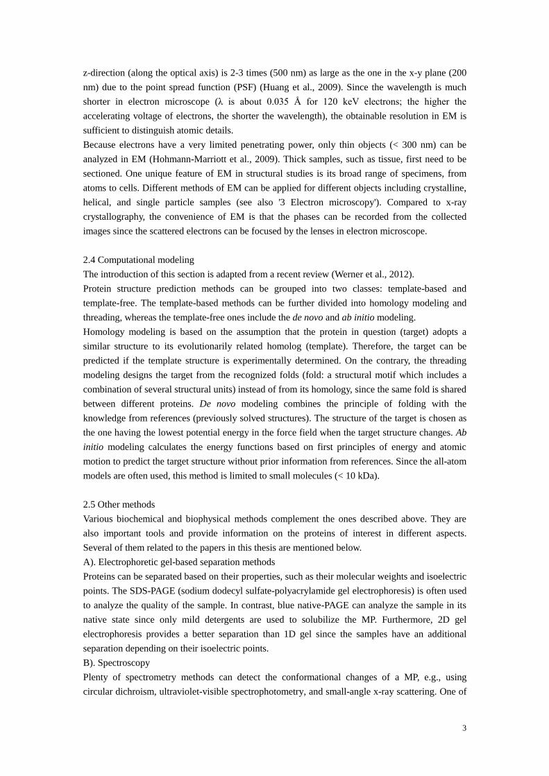
3
z-direction (along the optical axis) is 2-3 times (500 nm) as large as the one in the x-y plane (200
nm) due to the point spread function (PSF) (Huang et al., 2009). Since the wavelength is much
shorter in electron microscope (λ is about 0.035 Å for 120 keV electrons; the higher the
accelerating voltage of electrons, the shorter the wavelength), the obtainable resolution in EM is
sufficient to distinguish atomic details.
Because electrons have a very limited penetrating power, only thin objects (< 300 nm) can be
analyzed in EM (Hohmann-Marriott et al., 2009). Thick samples, such as tissue, first need to be
sectioned. One unique feature of EM in structural studies is its broad range of specimens, from
atoms to cells. Different methods of EM can be applied for different objects including crystalline,
helical, and single particle samples (see also '3 Electron microscopy'). Compared to x-ray
crystallography, the convenience of EM is that the phases can be recorded from the collected
images since the scattered electrons can be focused by the lenses in electron microscope.
2.4 Computational modeling
The introduction of this section is adapted from a recent review (Werner et al., 2012).
Protein structure prediction methods can be grouped into two classes: template-based and
template-free. The template-based methods can be further divided into homology modeling and
threading, whereas the template-free ones include the de novo and ab initio modeling.
Homology modeling is based on the assumption that the protein in question (target) adopts a
similar structure to its evolutionarily related homolog (template). Therefore, the target can be
predicted if the template structure is experimentally determined. On the contrary, the threading
modeling designs the target from the recognized folds (fold: a structural motif which includes a
combination of several structural units) instead of from its homology, since the same fold is shared
between different proteins. De novo modeling combines the principle of folding with the
knowledge from references (previously solved structures). The structure of the target is chosen as
the one having the lowest potential energy in the force field when the target structure changes. Ab
initio modeling calculates the energy functions based on first principles of energy and atomic
motion to predict the target structure without prior information from references. Since the all-atom
models are often used, this method is limited to small molecules (< 10 kDa).
2.5 Other methods
Various biochemical and biophysical methods complement the ones described above. They are
also important tools and provide information on the proteins of interest in different aspects.
Several of them related to the papers in this thesis are mentioned below.
A). Electrophoretic gel-based separation methods
Proteins can be separated based on their properties, such as their molecular weights and isoelectric
points. The SDS-PAGE (sodium dodecyl sulfate-polyacrylamide gel electrophoresis) is often used
to analyze the quality of the sample. In contrast, blue native-PAGE can analyze the sample in its
native state since only mild detergents are used to solubilize the MP. Furthermore, 2D gel
electrophoresis provides a better separation than 1D gel since the samples have an additional
separation depending on their isoelectric points.
B). Spectroscopy
Plenty of spectrometry methods can detect the conformational changes of a MP, e.g., using
circular dichroism, ultraviolet-visible spectrophotometry, and small-angle x-ray scattering. One of

4
them, mass spectrometry was used in paper I to validate the protein sample. Mass spectrometry
identifies samples by their mass to charge ratios. Furthermore, the conformational alteration of a
MP may lead to a change in its solvent accessibility, which can be recorded with the help of the
mass exchange between the hydrogen and deuterium atoms.
C). Fluorescence microscopy
This technique can record the signal from the proteins labeled with fluorescent molecules. Its
application includes protein-protein interactions, protein folding, and protein location.
2.6 Membrane protein structures
More than 50% of the current drugs are targeted to MPs (Drews, 2000). However, MP structures
occupy only approximately 2% among the ones deposited in the protein database (PDB), much
less than the soluble proteins (98%). The majority of solved MP structures are determined by x-ray
crystallography, with approximately 2% by EM.
The first structure solved by x-ray crystallography was a soluble protein (Kendrew et al., 1958).
Nearly 20 years later, the first MP structure was published to an intermediate resolution
(Henderson and Unwin, 1975). After another 10 years, the first α-helical MP atomic structure was
available (Deisenhofer et al., 1985) together with the β-barrels MP structure (Weiss et al., 1990).
With the advent of cryo (data is collected from the specimens at low temperatures)-EM and
modern microscopes, Henderson and his colleagues established the method of electron
crystallography (EC) (Henderson et al., 1990; Henderson et al., 1986) and determined the first MP
structure at atomic resolution using this method (Henderson et al., 1990). The highest resolution
(1.9 Å) is obtained by EC (AQP0, PDB: 2B6O, (Gonen et al., 2005)) among all structures
determined in EM so far. A MP (TRPV1, PDB: 3J5P and EMD-5778, (Liao et al., 2013)) was
determined at 3.3 Å by single particle reconstruction (SPR) using a direct detector.
3 Electron microscopy
Since the topic on this thesis is to use EM to analyze the MP structure, EM is discussed in the
following text.
3.1 The electron microscope
The electron microscope can provide high resolution information but it is costly. Fig. 1 shows the
Jeol 3000SFF electron microscope. The main components are: electron source, lens system,
specimen stage, and recording system.
3.1.1 Source
Electrons can be generated by different kinds of source. A tungsten or lanthanum hexaboride
filament is used in the thermal emission gun. The field emission gun can work at room
temperature, where electrons are emitted by application of a strong electric potential to the tip.
Since the field emission gun has advantages in providing a more coherent and brighter
illumination which are beneficial for determination of the structure to a higher resolution, this kind
of source is most frequently used in data collection. Thermal emission guns can work efficiently in
screening negatively stained samples (negative staining technique is introduced in '5.4 Sample
preparation').

5
Fig. 1. The Jeol 3000SFF electron microscope. The schematic drawing (A) and the corresponding
components of the microscope (B) are linked by arrows. For clarity, the intermediate and
projector lenses are not shown. These lenses are for magnification purposes. The image plane is
represented by the phosphorous screen, one of the recording systems. This figure is adapted from
Martin Lindahl's course slides (HL2026), 2010.
3.1.2 Lens and aperture
The electromagnetic lenses in electron microscope perform a similar function as the ones in light
microscope, to focus the beam. In contrast, they are made of wire coils, instead of the glass in light
microscope. The current flowing through the coils generates a magnetic field, which rotates the
beam. The lenses can be divided into three categories: condensor, objective, and projector
(including the intermediate lenses) lenses. 1) The condensor lenses determine the illuminated area;
2) The objective lens acts to primarily focus the beam and it initially magnifies the image as well;
3) The normal function of the projector and intermediate lenses is to magnify the image coming
from the objective lens and to project the magnified image onto a recording system. Either a
magnified image or a magnified electron diffraction pattern can be recorded by properly
positioning the projector lens system. An aperture, a metal disk with a hole in the center, is always
inserted into the lenses to limit the illuminated angles.
No lens is perfect and the main aberrations are spherical and chromatic ones, which reduce the
image resolution. On the other hand, the spherical aberration of the objective lens together with
defocusing gives contrast to the samples which makes them visible in the image.
3.1.3 Stage
The specimen holder carrying the samples can be inserted into the stage, by either top- or
side-entering. The axial symmetry design of the top-entry holder minimizes vibration and
specimen drift induced by thermal expansion of the holder (Fujiyoshi, 1998), whereas the
advantage of the side-entry holder is its convenience to tilt the specimen in data collection. The
modern cryo-transfer device allows the exchange of specimen in less than 10 minutes (Fujiyoshi,
1998).

6
3.1.4 Recording system
The exit electrons carrying sample information are visualized on the viewing screen or recorded
on a detector such as photographic film or camera. Photographic film emulsions contain silver
halide grains. When electrons hit the emulsion, silver halide is converted to metallic silver. After
developing and fixing, the exposed regions appear as dark areas on the supporting film (Kitts,
1996). Charge coupled devices (CCDs) collect the data via converting the incident electrons to
visible light followed by formation of an electronic read-out. Direct detectors avoid the
intermediate light conversion step and record the incident electrons directly (Faruqi and McMullan,
2011).
Detector performance can be evaluated quantitatively using the detective quantum efficiency
(DQE), which describes how effectively the camera can produce an image. Compared to CCD,
film has a higher DQE (meaning having a superior contrast performance), detects a larger number
of available pixels, and works better for information at higher resolutions (Faruqi and McMullan,
2011). On the other hand, CCD offers much greater linearity in a dynamic range (Wang and
Downing, 2011) and works better than film for information at low resolutions (Faruqi and
Henderson, 2007). Besides that, CCD provides on-line results and avoids the tediously digitizing
process of films. The K2 Summit in super-resolution mode (the new generation of a direct detector
from Gatan) has the highest DQE among the three detectors mentioned above (Ruskin et al., 2013).
The properties of having very low noise and a high DQE in the direct detector make it possible to
detect small and low-contrast samples (Li et al., 2013). Furthermore, since a direct detector
records the data at high speeds, the beam-induced motion of the particles in data collection can be
corrected (Li et al., 2013). This rapidly developing technology has already been applied to
determine the structure of a number of proteins (Allegretti et al., 2014; Amunts et al., 2014; Cao et
al., 2013a; Li et al., 2013; Liao et al., 2013; Lu et al., 2014).
3.1.5 High voltage and high vacuum
Since the wavelength is inversely proportional to the square root of the accelerating voltage, a
higher voltage results in a shorter wavelength, which can theoretically enhance detection of the
specimen at a higher resolution. Choosing a higher voltage also improves the data collection in
several aspects: a flatter Ewald sphere, decreased events of double-scattering, and minimization of
the influence of specimen charging. Thus it makes data collection possible from thicker specimens
(Henderson, 1995; Massover, 2007).
When electrons travel through the microscope, they are easily scattered. In order to obtain a
coherent electron beam, it is necessary to maintain a high vacuum in microscope. Several pumps
work together, each with its own efficiency. The high vacuum in microscope makes the
observation of live samples impossible. Therefore, the samples are either directly frozen in
vitrified ice or embedded in other media which are discussed in ' 5.4 Sample preparation'.
3.2 Methods in electron microscopy
Only thin samples can be analyzed in EM and these samples usually can only sustain one exposure
due to the high radiation damage. Therefore, only one image, a projection of a 3D object along the
beam axis is collected each time. The 'Central Section Theorem' (De Rosier and Klug, 1968) states
that the Fourier transform of a projection image forms a central section in the 3D Fourier
transform of the object. Therefore, by combination of images collected at different directions to

7
Fig. 2. 3D reconstruction in EM. The images of an object (represented by a duck) are collected at
different directions. These images are Fourier transformed and combined together to reconstruct
back to the duck. The reconstruction process can be performed either in reciprocal space or in real
space. The black arrows (indicating the beam directions in the left panel), thick lines (representing
recorded images in the left panel), and thin lines (corresponding to central sections in the middle
panel) are depicted.
fill Fourier space, the object can be reconstructed (Fig. 2).
EC, SPR, and electron tomography (ET) are three major methods in EM. Although these methods
are suitable for different kinds of sample and differ in detail, the principles (the Central Section
Theorem and reconstruction process) are similar.
3.2.1 Electron crystallography
2D crystals, where the protein molecules are ordered in 2D, are analyzed in EC. This method is
particularly suitable for studying of MPs, which are reconstituted into lipid membranes (see also
'5.3 Two dimensional crystallization' and '5.5 Electron crystallography image processing').
Since the tilt angles accessible in microscope are limited to around ± 70°, a certain part of data is
missing. This so called missing cone problem leads to elongation of the structure along the beam
direction (z-axis, perpendicular to the x-y plane) and the resolution along the z-axis is worse, as
compared to the one in the x-y plane (anisotropic resolution). However, missing cone may not be a
serious problem when the images tilted to high angles are included (Chiu, 1993; Ford and
Holzenburg, 2008).
EC is used to study MP structures in papers I-III and 2D crystals from different MPs are analyzed
in all papers included in this thesis.
3.2.2 Single particle reconstruction
SPR is a method to reconstruct the object from images of many identical protein molecules. These
protein molecules are separated (thus called single particles), instead of forming 2D crystals as in
EC. Ideally, the particles analyzed in SPR are oriented randomly on the grid, although in some
cases, they have preferred orientations (Special methods are applied to solve the structure of the
objects in these cases, such as the random conical tilt reconstruction technique (Radermacher et al.,
1987)). The orientation of each particle is assigned by either the common line method if there is
no reference or projection matching with a reference. Since the particles are randomly oriented in
the majority of cases, there is no missing cone problem in SPR. The advantages of SPR are: 1)
crystal formation is not needed which is still the bottleneck in EC; 2) the data collection can be
automated; and 3) sample preparation and data collection are easier as compared to EC. The main

8
limitation for this method is that only proteins with large molecular weights (the cutoff is 250 kDa,
(Unger, 2001)) are suitable, since these particles are large enough to be precisely aligned to each
other to increase the signal-to-noise ratio.
I applied a SPR procedure to process the 2D crystal images in paper IV.
3.2.3 Electron tomography
ET allows determining the structure of individual cell organelles and bacterial cells to nanometer
resolutions (Unger, 2001). One unique feature of ET is that the whole data set is built from a tilt
series of images taken of a single copy of the object. Therefore, heterogeneous samples can be
studied using this method (Zhang and Ren, 2012). Since the same object is exposed several times
in a tilt series, the sample would be damaged if the same electron dose was used as in EC or SPR.
Therefore, each image is collected at a lower dose, making the total dose over the entire tilt series
comparable to the one used in low dose imaging (Subramaniam and Milne, 2004; Unger, 2001).
When the sample is collected from a single-axis tilt, the data has a missing wedge. The
improvement using double-tilt can alleviate this problem and gives a missing pyramid in the data.
Fiducial markers are used for the alignment purpose due to the low contrast and possible sample
movement induced by the beam (Subramaniam and Milne, 2004).
3.2.4 Helical reconstruction
Some proteins are arranged to have a helical symmetry, in which the protein molecules can be
superimposed to each other by rotational and translational movements along the screw axis.
Therefore in principle, one image contains all views of the protein molecule which are sufficient
for reconstructing the object (Unger, 2001). Furthermore, there is no missing part in the data. The
EC and SPR methods can be combined together to solve their structures (Unger, 2001).
Several MP structures solved by this method have reached near atomic resolutions, such as the
acetylcholine receptor (Miyazawa et al., 2003).
3.3 Special issues in EM
Several issues specific to EM are discussed in this section.
3.3.1 Radiation damage
During data collection, the electrons interact with the sample and inevitably damage it. The
damage can be caused by heating, mass loss, breakage of covalent bonds, charge alteration and
ionization, and generation of free-radicals (Massover, 2007). Several approaches have been
developed to reduce the electron beam damage. Low-dose exposures ( ~15 e−/Å
2) and 'minimum
dose systems' (three modes of operation: search, focus, and photo modes) are used for data
collection (Fujiyoshi, 1998). The samples are usually protected at low temperatures during the
entire procedure. The lower temperature of liquid helium (4K) provides at least two times more
protection than using liquid nitrogen (77K) (Fujiyoshi, 1998). The higher voltage reduces the
radiation damage as well (Henderson, 1995; Massover, 2007).
3.3.2 Image and diffraction
When the electron beam passes through the sample in microscope, it interacts with the sample and
the interactions can be divided into two classes: elastic and inelastic scattering. In the former, the

9
energy (wavelength) of the electrons does not change but the direction of them changes; in the
latter, the energy of the electrons changes. The transferred energy in inelastic scattering changes
the state of the sample and then damages it. Only elastic scattering waves contribute to the sample
signal in an image and a diffraction pattern, whereas inelastic scattering gives rise to background
noise (Amos et al., 1982).
One great advantage of EM is that both images and diffraction patterns can be collected, therefore,
the amplitudes extracted from the diffraction pattern and phases obtained from the image can be
combined together to solve the structure. The image formation can be regarded as the interference
of the elastically scattered waves and the unscattered waves (Amos et al., 1982). On the other
hand, the diffraction formation does not rely on interference, and only the reflections (spots in the
diffraction pattern) are recorded. The higher frequency waves give the diffraction spots further
away from the origin (thus the diffraction extends to a higher resolution). Since only intensity can
be recorded in the recording system, the phase information in diffraction is lost.
3.3.3 CTF effect
In reality, image formation is influenced by the phase contrast transfer function (CTF). The final
image obtained in microscope can be described as the projection of the object convoluted with the
PSF. Regarding that convolution in real space corresponds to multiplication in Fourier space
(reciprocal space) mathematically, the previous sentence can be described as: Fourier transform of
the final image equals Fourier transform of the projection multiplied by the CTF (Wade, 1992).
The CTF effect is generated by defocusing and the spherical aberration of the objective lens, and
can be calculated according to the formula: CTF (θ) = -2 sin [(2π/λ)(-zθ2/2
+ Csθ
4/4)], where θ is
the scattering angle; λ is the wavelength; Cs is the spherical aberration; and z is the defocus value,
positive if the image is taken at underfocus (Wade, 1992). In practice, the CTF effect is modified
by several other optical factors, including the chromatic aberration of the objective lens, partial
coherence of the illuminating beam, astigmatism, and amplitude contrast (Amos et al., 1982).
Due to the sine expression of the CTF effect, the phases are shifted by 180° for the odd-numbered
Thon ring regions. The CTF effect should be corrected for all images recorded in microscope.
4 Individual projects
In this thesis, three MP structures are analyzed using EM. They are a putative potassium channel
(Kch), a metabolic enzyme (MGST1), and a secondary transporter (MelBec). Several important
issues are picked up, since all these proteins are actively studied.
4.1 Potassium channel
Potassium (K+) channels ubiquitously exist in all kingdoms of life, except for some parasites and
inner organelles (Kuo et al., 2005). The main function of K+ channels is to transport K
+ ions
between the extracellular environment and the cell, since the cell membrane is almost
impermeable to K+ ions. Depending on the number of TMs in the protein and different properties
of the protein, K+ channels can be divided into three categories: voltage gated potassium (Kv),
inwardly rectifying potassium (Kir), and tandem pore domain potassium (K2P) channels
(Buckingham et al., 2005). Kv channels (6 TMs) sense the membrane potential change (Long et
al., 2005a, b; Long et al., 2007); Kir channels (2 TMs) transport K+ ions from the extracellular
environment to the cell (Kuo et al, 2003); and K2P channels (4 TMs) are usually constitutively
10
open and set the membrane potential (Butterwick and MacKinnon, 2010; Miller and Long, 2012).
Furthermore, K+ channels can be stimulated by various kinds of ligand. This group of channel is
called Kligand (ligand gated potassium) channel, which contains either 2 or 6 TMs (Kuo et al.,
2003a).
Structurally, a K+ channel can be divided into two parts: the pore-forming domain and the
regulatory domain. The pore-forming domain contains 2 TMs in each monomer and the regulatory
domain is different in each class of K+ channels. The pore-forming domains are in charge of
conduction of K+ ions and are embedded in lipid membranes. On the other hand, the regulatory
domains sense various kinds of stimulus, which control the closing and opening of the
pore-forming domains (called gating (Jiang et al., 2003)). Four K+ channels assemble together to
form a tetramer and the tetramerization is required for channel functioning (Doyle et al., 1998).
4.1.1 Pore-forming domain
Pore-forming domain is the smallest functional unit in the channel that can conduct K+ ions
efficiently (107 ions channel
-1s
-1) (Sansom et al., 2002). K
+ ions are selected among other ions
when transported through the K+ channel (the selectivity ratio of K
+ ions to sodium (Na
+) ions is
more than 10000, (Doyle et al., 1998)).
The pore-forming domain contains an outer helix, a pore helix, the selectivity filter (SF), and an
inner helix from the N- to C-terminus (Fig. 3). K+ ions move down the electrochemical gradient
from the helical bundle in the intracellular side, to the central water-filled cavity, next through the
SF, and eventually to the extracellular side. K+ ions occupy several positions in the SF.
4.1.1.1 Selectivity filter
The conventional K+ channel has a conserved sequence TVGYG
75-79 (the sequence is based on
KcsA, a bacterial K+ channel from Streptomyces lividans), called SF, where K
+ ions are conducted
efficiently and selectively (Doyle et al., 1998). In the ion conduction pathway shown in Fig. 3, K+
ions are only dehydrated in the SF (S1-S4) and kept hydrated in other regions (Sc at the
intracellular side and S0 and Sext at the extracellular side). Four oxygens in the main chain of
TVGY75-78
together with the one in the side chain of T75
point to the ion conduction pathway and
surround the dehydrated K+ ions. Each K
+ ion sits in the middle of two oxygen layers and four K
+
ions can bind to four such evenly spaced K+ binding sites (S1-S4) in the SF, with one K
+ ion in
each binding site. Since the free energy difference between the K+ ions surrounded by waters and
the ones surrounded by oxygens in the SF is small, K+ ions can be transported across the
membrane efficiently. On the other hand, binding to the SF for Na+ ions is energetically
unfavorable, which partially explains the selectivity of K+ ions (Doyle et al., 1998; Lockless et al.,
2007).
Four K+ ions adopt two configurations in the SF, either 1,3 or 2,4 configuration. In the 1,3
configuration, two K+ ions occupy the S1 and S3 sites with two waters in the S2 and S4 sites. In
the 2,4 configuration, two K+ ions occupy the S2 and S4 sites with two waters in the S1 and S3
sites (Morais-Cabral et al., 2001; Zhou and MacKinnon, 2004; Zhou and MacKinnon, 2003; Zhou
et al., 2001). The shift between two configurations can be achieved when a third ion enters from
one side and pushes one ion away from another side or by movement of the ion-water queue
(MacKinnon, 2003; Morais-Cabral et al., 2001; Zhou and MacKinnon, 2003; Zhou et al., 2001).
The energy transfer cost between these two configurations is low (Morais-Cabral et al., 2001). The

11
Fig. 3 The structure of KcsA, a prototype of K+ channel. The transmembrane part of KcsA is
homologous to the pore-forming domain of other K+ channels. The conductive state of KcsA
(PDB: 1K4C) is shown here. K+ ions (purple balls) and water (red balls) are depicted. The SF
together with observed K+ ion binding sites (Sext, S0, S1-S4, and Sc) in the ion conduction
pathway and the glycine hinge (Gly99) are labeled. EC: extracellular side; IC: intracellular side;
OH: outer helix; IH: inner helix; PH: pore helix; HB: helical bundle. Only two diagonal
monomers in the tetramer are shown.
repulsion of two occupied K+ ions in each configuration further facilitates the conduction of ions
(MacKinnon, 2003; Zhou and MacKinnon, 2003). Other factors maintaining the integrity of the
SF (such as the proteinous environment near the SF and the bound ions) are also important to keep
conduction of K+ ions efficient and selective (Alam and Jiang, 2011; MacKinnon, 2003; Nimigean
and Allen, 2011).
4.1.1.2 Two gates
The majority of K+ channels are closed in the resting state, opened with certain stimuli, and then
enter into a nonconductive state (Norton and Gulbis, 2010). Except for some K2P members that
are constitutively open, gating is tightly regulated in other K+ channels (Brohawn et al., 2012;
Miller and Long, 2012). Two kinds of gate exist, where the extracellular one includes the SF and
the intracellular one is at the position where the inner helices bend (Imai et al., 2010).
The intracellular one was proposed originally by a structural comparison of KcsA (closed state)
and MthK (a calcium induced K+ channel from Methanobacterium thermoautotrophicum, in an

12
Fig. 4 Two gates in K+ channels controlling conduction of K
+ ions. (A) The intracellular gate
where the inner helices bend. KcsA in a closed state (PDB: 1K4C, blue), KcsA in an open state
(PDB: 3F5W, red), and MthK in an open state (PDB: 3LDC, orange) are viewed from the
intracellular side. The glycine hinges are located in a similar position in these channels. IH: inner
helix; OH: outer helix. (B) The extracellular gate in the SF. The conduction (PDB: 1K4C, blue),
C-type inactivation (PDB: 3F5W, magenta), and flipped (PDB: 2ATK, gray) states of KcsA are
depicted. Only two diagonal monomers are displayed in (B).
open state). The inner helices cross to form a helical bundle (Fig. 3) to block the conduction of K+
ions in KcsA; on the other hand, the inner helices are bent and splayed open after a glycine in MthK
(Jiang et al., 2002b) (Fig. 4A). These glycine hinges are conserved and located in a similar
position in several bacterial K+ channels (such as G99 in KcsA and G83 in MthK shown in Fig.
4A). In eukaryotic Kv channels, PXP (P is proline and X is any residue) replaces the glycine hinge
to bend the sixth helices (corresponding to the inner helices in the 2 TMs channel) for conduction
of K+
ions (Long et al., 2005b).
The extracellular gate is located in the SF and a subtle conformational change in this gate can
result in nonconduction. Several distorted SF structures have been observed in KcsA (Fig. 4B),
including high Na+/low K
+ (PDB: 1K4D, (Zhou et al., 2001)), C-type inactivation (PDB: 3F5W
and 3F7V, (Cuello et al., 2010)), and flipped (PDB: 2ATK, (Cordero-Morales et al., 2006) and
PDB: 3OGC (Cheng et al., 2011)) ones. When the SF adopts a structure that deviates from the
conductive state (PDB: 1K4C, Figs. 3 and 4B), the channel may not be able to conduct K+ ions,
regardless whether the intracellular gate is open or not (Cuello et al., 2010). These two gates are
regulated by specific regulatory domains located N- and/or C- terminally to the pore-forming
domain.
4.1.2 Regulatory domains
Besides the pore-forming domains, Kv, Kir, and Kligand channels possess their own regulatory
domains which regulate the gating of the channels. All regulatory domains have some freedom
relative to the pore-forming domains and a channel may have more than one regulatory domains.
The voltage gated sensor domains (VSDs) are located at the periphery of the Kv channel (Chen et

13
Fig. 5 Extracellular view of MlotiK1 (a
non-voltage gated K+ channel from
Mesorhizobium loti, PDB: 3BEH). Four
monomers (in different colors) form a
biological unit. The VSD (in an ellipse)
is composed of TMs 1 to 4 (S1-S4) and
the pore-forming domain (in a
rectangle) consists of S5 (corresponds
to the outer helix in KcsA shown in Fig.
3) and S6 (corresponds to the inner
helix in KcsA shown in Fig. 3). The
pore helix is labeled as PH.
al., 2010; Clayton et al., 2008; Long et al., 2005a; Long et al., 2007) and sense the electron change
in the membrane (Aggarwal and MacKinnon, 1996; Tombola et al., 2006). The cytosolic domains
in Kir channels are located below their pore-forming domains and provide the binding sites for
diverse intracellular regulatory mediators to interact (Hibino et al., 2010). Kligand channels have
diverse kinds of cytosolic domain for their respective ligands, e.g., CNBD (cyclic
nucleotide-binding domain, (Clayton et al., 2004)) and RCK (the regulator of the conductance of
K+ ion, (Jiang et al., 2001)) domains.
4.1.2.1 Voltage gated sensor domain
Since Kch studied in this thesis has a domain that corresponds to the VSD in a Kv channel, VSD
is introduced in this section.
The VSDs have been found in other voltage gated channels and enzymes as well (Catterall, 2010b;
Murata et al., 2005; Ramsey et al., 2006; Sasaki et al., 2006). The VSD separates from its
pore-forming domain and weakly attaches to the pore-forming domain from the adjacent subunit
(Fig. 5), which indicates that the VSD has mobility relative to the pore-forming domain.
Up to eight positively charged residues have been found in the fourth helix (S4) in the VSD (Kuo
et al., 2005), and among them, four residues (R1-R4) at the N-terminus of S4 are the most crucial
ones responsible for charge movement during activation (Aggarwal and MacKinnon, 1996; Swartz,
2008). These positive residues are intercalated by hydrophobic residues (Kuo et al., 2005). In fact,
this pattern rather than the positive residues determines electron charge translocation (Xu et al.,
2010). The positive charges are counter-balanced by several negatively charged residues (E183,
E226, E154, E236, and D259, based on PDB: 2R9R) located in other helices in the VSD (Chen et
al., 2010; Long et al., 2005b; Long et al., 2007). These interactions are believed to assist the
movement of S4 in the focused electric field across the membrane (a hydrophobic region of
approximately 10 Å thickness, separated by the water assessable crevices at both ends) during
gating (Catterall, 2010a; Chen et al., 2010; Long et al., 2007; Tombola et al., 2006).
4.1.3 Kch
Kch, a putative ligand K+ channel in Escherichia coli (E. coli), was first reported by Milkman
14
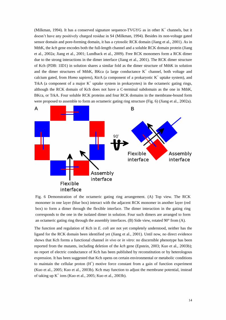
Fig. 6 Demonstration of the octameric gating ring arrangement. (A) Top view. The RCK
monomer in one layer (blue box) interact with the adjacent RCK monomer in another layer (red
box) to form a dimer through the flexible interface. The dimer interaction in the gating ring
corresponds to the one in the isolated dimer in solution. Four such dimers are arranged to form
an octameric gating ring through the assembly interfaces. (B) Side view, rotated 90° from (A).
(Milkman, 1994). It has a conserved signature sequence-TVGYG as in other K+ channels, but it
doesn’t have any positively charged residue in S4 (Milkman, 1994). Besides its non-voltage gated
sensor domain and pore-forming domain, it has a cytosolic RCK domain (Jiang et al., 2001). As in
MthK, the kch gene encodes both the full-length channel and a soluble RCK domain protein (Jiang
et al., 2002a; Jiang et al., 2001; Lundback et al., 2009). Free RCK monomers form a RCK dimer
due to the strong interactions in the dimer interface (Jiang et al., 2001). The RCK dimer structure
of Kch (PDB: 1ID1) in solution shares a similar fold as the dimer structure of MthK in solution
and the dimer structures of MthK, BKca (a large conductance K+ channel, both voltage and
calcium gated, from Homo sapiens), KtrA (a component of a prokaryotic K+ uptake system), and
TrkA (a component of a major K+ uptake system in prokaryotes) in the octameric gating rings,
although the RCK domain of Kch does not have a C-terminal subdomain as the one in MthK,
BKca, or TrkA. Four soluble RCK proteins and four RCK domains in the membrane-bound form
were proposed to assemble to form an octameric gating ring structure (Fig. 6) (Jiang et al., 2002a).
The function and regulation of Kch in E. coli are not yet completely understood, neither has the
ligand for the RCK domain been identified yet (Jiang et al., 2001). Until now, no direct evidence
shows that Kch forms a functional channel in vivo or in vitro: no discernible phenotype has been
reported from the mutants, including deletion of the kch gene (Epstein, 2003; Kuo et al., 2003b);
no report of electric conductance of Kch has been published by reconstitution or by heterologous
expression. It has been suggested that Kch opens on certain environmental or metabolic conditions
to maintain the cellular proton (H+) motive force constant from a gain of function experiment
(Kuo et al., 2005; Kuo et al., 2003b). Kch may function to adjust the membrane potential, instead
of taking up K+ ions (Kuo et al., 2005; Kuo et al., 2003b).
15
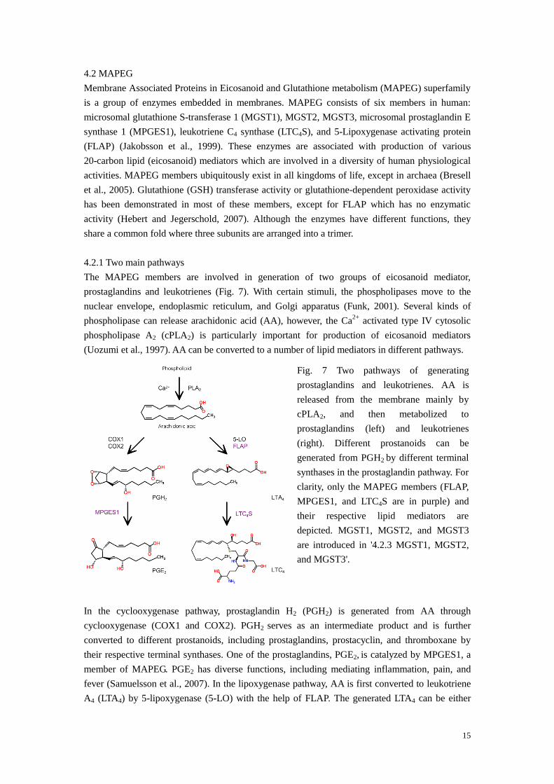
Fig. 7 Two pathways of generating
prostaglandins and leukotrienes. AA is
released from the membrane mainly by
cPLA2, and then metabolized to
prostaglandins (left) and leukotrienes
(right). Different prostanoids can be
generated from PGH2 by different terminal
synthases in the prostaglandin pathway. For
clarity, only the MAPEG members (FLAP,
MPGES1, and LTC4S are in purple) and
their respective lipid mediators are
depicted. MGST1, MGST2, and MGST3
are introduced in '4.2.3 MGST1, MGST2,
and MGST3'.
4.2 MAPEG
Membrane Associated Proteins in Eicosanoid and Glutathione metabolism (MAPEG) superfamily
is a group of enzymes embedded in membranes. MAPEG consists of six members in human:
microsomal glutathione S-transferase 1 (MGST1), MGST2, MGST3, microsomal prostaglandin E
synthase 1 (MPGES1), leukotriene C4 synthase (LTC4S), and 5-Lipoxygenase activating protein
(FLAP) (Jakobsson et al., 1999). These enzymes are associated with production of various
20-carbon lipid (eicosanoid) mediators which are involved in a diversity of human physiological
activities. MAPEG members ubiquitously exist in all kingdoms of life, except in archaea (Bresell
et al., 2005). Glutathione (GSH) transferase activity or glutathione-dependent peroxidase activity
has been demonstrated in most of these members, except for FLAP which has no enzymatic
activity (Hebert and Jegerschold, 2007). Although the enzymes have different functions, they
share a common fold where three subunits are arranged into a trimer.
4.2.1 Two main pathways
The MAPEG members are involved in generation of two groups of eicosanoid mediator,
prostaglandins and leukotrienes (Fig. 7). With certain stimuli, the phospholipases move to the
nuclear envelope, endoplasmic reticulum, and Golgi apparatus (Funk, 2001). Several kinds of
phospholipase can release arachidonic acid (AA), however, the Ca2+
activated type IV cytosolic
phospholipase A2 (cPLA2) is particularly important for production of eicosanoid mediators
(Uozumi et al., 1997). AA can be converted to a number of lipid mediators in different pathways.
In the cyclooxygenase pathway, prostaglandin H2 (PGH2) is generated from AA through
cyclooxygenase (COX1 and COX2). PGH2 serves as an intermediate product and is further
converted to different prostanoids, including prostaglandins, prostacyclin, and thromboxane by
their respective terminal synthases. One of the prostaglandins, PGE2, is catalyzed by MPGES1, a
member of MAPEG. PGE2 has diverse functions, including mediating inflammation, pain, and
fever (Samuelsson et al., 2007). In the lipoxygenase pathway, AA is first converted to leukotriene
A4 (LTA4) by 5-lipoxygenase (5-LO) with the help of FLAP. The generated LTA4 can be either

16
hydrolyzed to produce leukotriene B4 (LTB4) by LTA4 hydrolase or conjugated with GSH to
produce leukotriene C4 (LTC4) by LTC4S. LTC4 and its further metabolized products, leukotriene
D4 (LTD4) and leukotriene E4 (LTE4), comprise the cysteinyl leukotrienes, which are involved in
the inflammation processes, such as asthma (Evans et al., 2008; Martinez Molina et al., 2007).
Besides these two well-studied pathways, AA can be metabolized through a third cytochrome
P450-dependent pathway, where epoxyeicosatrienoic acids are produced (Evans et al., 2008;
Zeldin, 2001). Since no MAPEG member exits in the third pathway, the enzymes in the first two
pathways are discussed.
4.2.2 Structures of FLAP, LTC4S, and MPGES1
The MAPEG members share a common fold. The structure of FLAP (PDB: 2Q7M, (Ferguson et
al., 2007)) aligns well with the structure of LTC4S (PDB: 2UUH, (Martinez Molina et al., 2007)
and PDB: 2PNO, (Ago et al., 2007)) as shown in Fig. 8A. The GSH binding site was observed and
the secondary substrate (LTA4) binding site was proposed from a structurally similar detergent
molecule (n-dodecyl β-maltoside (DDM)) bound in the LTC4S structure (Martinez Molina et al.,
2007). On the other hand, the FLAP structure (PDB: 2Q7M) provided the first view of a MAPEG
member with its inhibitor (MK591, depicted in red in Figs. 8A and B) which competes with AA
(Mancini et al., 1993). The GSH binding site (Fig. 8C) and the inhibitor binding site (Fig. 8B) do
not overlap. However, the long acyl chain in the secondary substrate may insert into the inhibitor
binding site (Fig. 8C). Another special feature in FLAP is its long C2 loop between the helices 3
and 4. Considering its closeness to the proposed secondary substrate binding site and the inhibitor
binding site, as well as the results from the mutagenesis data (Ferguson et al., 2007), it is possible
that this loop plays a role in AA transport.
MPGES1 carrying out the isomerization reaction of PGH2 to prostaglandin E2 (PGE2), is a
member of MAPEG superfamily. The overall MPGES1 structures in an open conformation (PDB:
4AL0 and 4AL1, (Sjogren et al., 2013) and PDB: 4BPM, (Li et al., 2014)) are similar to the
LTC4S structure (PDB: 2PNO and 2UUH). However, the cytosolic half of TM 1 and TM 2 is
displaced in the closed MPGES1 conformation (PDB: 3DWW, (Jegerschold et al., 2008)) as
shown in Fig. 8D. Although the GSH binding sites of these two MAPEG members in open
conformations are conserved (the GSH binding site of LTC4S is shown in Fig. 8C), different
residues, S127 in MPGES1 and R104 in LTC4S (corresponding to R126 in MPGES1) are
proposed to stabilize the thiol group of GSH (Hammarberg et al., 2009; Jegerschold et al., 2008;
Sjogren et al., 2013).

17
Fig. 8 Structural comparison of FLAP, LTC4S, and MPGES1. (A) Alignment of FLAP (PDB:
2Q7M, blue) and LTC4S (PDB: 2UUH, brown). (B) Inhibitor binding site in FLAP. (C) GSH and
DDM binding sites in LTC4S. DDM is proposed to occupy the secondary substrate binding site.
Adjacent subunits in the trimer are depicted in different colors in (B and C). (D) MPGES1 (in a
closed state, PDB: 3DWW, purple) is compared with LTC4S. The displacement of the cytosolic
half of TM 1 and TM 2 is via the K26-D75 salt bridge.
4.2.3 MGST1, MGST2, and MGST3
Glutathione transferases (GSTs) are a group of phase II detoxification enzymes, which conjugate
the electrophilic substrates with GSH (Fig. 9A) and make these substrates more water soluble to
be excreted easily (Hayes et al., 2005). They ubiquitously exist in most life forms and can be
divided into soluble and membrane-bound families. Although the members in these two classes

18
Fig. 9 GST activities and the rat MGST1 (rMGST1) structure. (A) GSH transferase reaction,
CDNB (2,4-Dinitrochlorobenzene) conjugates with GSH. (B) The 'dead-end' Meisenheimer
complex formation with TNB (trinitrobenzene). The crossover arrow indicates that the product
does not form. (C) Lipid peroxidase reaction. (D) Different GSH positions in MGST1 (newly
refined model in paper III, red) and MPGES1 (PDB: 4AL0, cyan). The GSH positions in
MPGES1 and LTC4S are similar and shown in Fig. 8C. The entrance of the secondary substrate
in rMGST1 is suggested to be located in the interface between two subunits (Holm et al., 2006).
perform similar reactions, the soluble ones are dimers and the membrane-bound ones are trimers
(Hayes et al., 2005).
MGST1, MGST2, and MGST3 are membrane-bound GSTs and all of them belong to the MAPEG
superfamily. MGST1 is abundant in human liver as well as in rat (McLellan et al., 1989;
Morgenstern et al., 1984). Besides the GSH transferase activity, it can reduce the oxidized lipids
by its peroxidase activity as well (Fig. 9C) (Mosialou et al., 1993). MGST1 has a special feature
that it can be activated to a large degree by various treatments (Morgenstern, 2005). One treatment,
alkylation of C49 with sulfhydryl reagents, e.g., N-ethylmaleimide can activate MGST1 up to
30-fold (Svensson et al., 2004). Although MGST1 has a high sequence identity to MPGES1 (38%),
it does not catalyze the isomerization of PGH2 as in MPGES1. GSH in MGST1 adopts an
extended conformation (red GSH in Fig. 9D), rather than the horseshoe-shaped conformations in
MPGES1 (PDB: 3DWW, 4AL0, and 4BPM, cyan in Fig. 9D) and LTC4S (PDB: 2PNO and
2UUH).
The functions of MGST2 and MGST3 are less understood in vivo. Both proteins may be involved
in the lipoxygenase pathway and can produce LTC4 from LTA4 in vitro (Jakobsson et al., 1996;
Jakobsson et al., 1997). It is suggested that MGST2 and MGST3 are structurally more close to
LTC4S than to MGST1, although their structures remain to be determined (Martinez Molina et al.,
2008).
4.2.4 Activity of MAPEG members
A). FLAP does not bind to GSH, nor does it have any enzymatic activity (Ferguson et al., 2007).
B). LTC4S does not react with CDNB, a typical substrate for measuring the GSH transferase
activity, nor does it have a lipid peroxidase activity (Ahmad et al., 2013). It catalyzes LTC4

19
production from LTA4.
C). MPGES1 has both GSH transferase and peroxidase activities (Thoren et al., 2003). Its main
function is to convert PGH2 to PGE2.
D). MGST1 has both GSH transferase and peroxidase activities (Morgenstern, 2005). It has broad
substrate specificities and mainly acts as a detoxification enzyme. It may protect the membrane
from oxidative stress in cell as well.
In the GSH transferase reaction, the Meisenheimer complex is formed as an intermediate step
followed by leaving of the halogen group (Fig. 9A). The Meisenheimer complex is accumulated
due to the absence of a leaving group when GSH reacts with TNB (trinitrobenzene) (Fig. 9B).
E). MGST2 reacts with CDNB and it also catalyzes a lipid peroxidase reaction (Ahmad et al.,
2013). It displays LTC4 production from LTA4 as well (Ahmad et al., 2013; Jakobsson et al.,
1996).
F). MGST3 shows a peroxidase activity, however, it does not react with CDNB (Jakobsson et al.,
1997).
4.3 Transporters
Cells have their plasma membranes to separate the inner parts of them from the extracellular
environments. Membranes are impermeable to most ions and substances, which require certain
proteins for their transportation. These proteins can be classified as channels (see also '4.1
Potassium channel') and transporters (Gadsby, 2009).
4.3.1 Differences between channels and transporters
Channels and transporters carry out a similar task for living cells, transporting substrates across
the membrane. The structure of channels may or may not resemble the structure of transporters.
The fundamental differences distinguishing them (Gadsby, 2009) are summarized as follows:
A). The direction of transportation
Substrates are diffused through channels from the high electrochemical gradient side to the low
gradient side (downhill), whereas substrates are moved by transporters in an uphill direction.
Although uniporters transport the substrates down the solution gradient as in channels, the
substrates bind to the protein on one side and are translocated to the other side. This property
makes the structures of uniporters and transporters resemble each other.
B). Energy consumption
Downhill movement does not require energy, whereas uphill movement consumes energy. Thus,
either the primary energy (adenosine triphosphate, ATP) or the free energy stored in the
counter-transported substrate gradient could be utilized for transporters.
C). Opening in the conduction pathway
The essential difference between channels and transporters is whether the substrate conduction
pathway can be opened at both sides or allow opening at one side at a time. In a channel, the
conduction pathway is permeable at both ends when the gate is open. However, the conduction
pathway is never opened at both sides in a transporter. Instead, it is always closed at least at one
side. The transport usually develops occluded states, where the substrates are not accessible from
either end.
D). Translocation speed
The translocation speed for channels is fast, e.g., the K+ ions are conducted very efficiently, at near

20
Fig. 10 Alternating access model in a transport
cycle based on Jardetzky (1966) and Gadsby
(2009). Three main states are identified as
inward-facing (left), occluded (middle), and
outward-facing (right). The substrate
transported from the intracellular side of the
cell to the extracellular side is depicted as a
yellow ball and the counter-transported
substrate in a reversed direction is shown as a
red ball. The curved arrows indicate that both
kinds of substrates are accessible when the
intracellular gate is open (left) or the
extracellular gate is open (right). The N- and
C-terminal domains in a transporter are
depicted as two ellipses in different colors.
Notice that a transporter is never accessible to
both sides and all steps are reversible in the
cycle.
diffusion-limited rates (107 ions channel
-1s
-1) (Sansom et al., 2002), whereas the speed for
transporters is several hundred ions per channel per second. The main reasons for a slower
conduction of the substrates can be due to large conformational changes, substrates binding, and
closure of substrate conduction pathway in a transport cycle for transporters.
E). Current recording
For ion passengers, the current can be recorded from a single channel. However, the current is far
too small to be detected from a single transporter, since the translocation speed is several orders of
magnitude slower in transporters as compared to channels.
4.3.2 Alternating access model
The mechanism of transportation can be well explained by the alternating access model, where the
essence is that the substrate binding sites are accessible to one side of the membrane at a time in
one transport cycle (Jardetzky, 1966).
The cartoon in Fig. 10 demonstrates a simplified transport cycle to explain how the model works.
A transporter has three main states: inward-facing, occluded, and outward-facing. The substrate
conduction pathway is opened at the intracellular side in the inward-facing conformation (left icon)
and is opened at the extracellular side in the outward-facing conformation (right icon), with both
sides closed in the occluded conformation (middle icons). In the inward-facing conformation, the
transporter has a high affinity to the transported substrates, but a low affinity to the
counter-transported substrates. Then, the transported substrates can bind to the protein. The
binding triggers the structural rearrangements from the inward-facing to the occluded
conformation (middle up icon), which is followed by entering into the outward-facing
conformation. In the outward-facing conformation, the transported substrates are released into the
extracellular side due to their low affinities to the protein and a downhill gradient. Meanwhile, the
protein has a high affinity to the counter-transported substrates. After binding of the

21
counter-transported substrates, the protein turns to another occluded state (middle down icon),
followed by turning to the initial inward-facing state. This cycle can be reversed and the different
protein conformations and the corresponding affinities to different substrates determine the
direction of transportation. The alternating access model was proposed to explain the P-type
ATPases (primary transporters) initially and phosphorylation/dephosphorylation by ATP induces
the structural rearrangements of it. The original model with small adjustments can be applied to
other transporters as well.
4.3.3 Classification of transporters
The bacterial transporters can be classified into three main categories: primary transporters,
secondary transporters, and group translocation systems (Law et al., 2008). 1) The primary
transporters, such as ATPases and ATP-binding cassettes use the energy of hydrolysis of ATP for
pumping the substrates across the membrane; 2) The secondary transporters employ two kinds of
substrates, in which one kind of substrates travel downhill the gradient and another transport
uphill. ATP hydrolysis is not involved in this class, instead, secondary transporters use the free
energy from the movement of the substrates downhill to pump the other substrates uphill; 3) The
group translocation systems first allow the substrates to bind to the protein at one side of the
membrane, and then chemically modify them, followed by releasing them to the other side.
Secondary transporters pump a wide range of substrates and can be divided into symporter and
antiporter classes, depending on whether the substrates and counter-transported substrates move in
the same (symporter) or opposite (antiporter) directions across the membrane. Furthermore,
secondary transporters can be divided into over 100 families and superfamilies (Tsai and Ziegler,
2005). Since the structural studies of the transporter included in this thesis is from a secondary
transporter having a major facilitator superfamily (MFS) fold, this fold is discussed in the
following section.
The MFS presents the largest superfamily of the secondary transporters
(http://www.tcdb.org/search/result.php?tc=2.A.1, (Saier, 2000)) and accounts for about 25% of all
transporter proteins (Saier et al., 1999). The MFS members are ubiquitous in all kingdoms of life
and play vital roles in numerous physiological processes, e.g., glucose transporters in sugar
transportation (Shi, 2013; Yan, 2013a).
4.3.4 The major facilitator superfamily fold
Currently, a number of 3D structures of MFS members have been determined to atomic
resolutions, including uniporters, symporters, and antiporters (The information can be found at
http://blanco.biomol.uci.edu/mpstruc/. Several papers (e.g., (Yan, 2013a, b)) have listed some of
them, in addition to some intermediate resolution structures from EM (Tsai and Ziegler, 2010)).
Despite low sequence similarities and different kinetic mechanisms, the MFS members share a
common fold. The following description of the MFS fold is adapted from Shi (2013) and Yan
(2013a). Fig. 11A illustrates the general feature of the MFS fold.
All MFS members appear to function as monomers and the core of the MFS fold is composed of
12 TMs. The fold can be separated into two parts, the N- and C-terminal domains, with 6
consecutive TMs in each domain. These two domains, despite in a low sequence similarity, are
related to each other by a pseudo-twofold symmetry axis that is perpendicular to the membrane.
Furthermore, each domain is evolved from a pair of inverted 3 TMs repeats, which can be

22
Fig. 11 The MelBst structure (PDB: 4M64, Mol-A). (A) Extracellular side view shows a typical
MFS fold. The TM 1-3 and TM 7-9 are in yellow; the TM 4-6 and TM 10-12 are in red; and the
loops are in blue. TM 1-6 and TM 7-12 compose the N- and C-terminal domains, respectively.
(B) The proposed cation binding (left to the K377 and W128 part) and sugar binding (right to
K377 and W128) sites.
matched to each other by an approximate 180° rotation around an axis parallel to the membrane
(Madej et al., 2013). These two repeats are intertwined with one helix from one pair inserted into
the center of another pair. Due to the pseudo-twofold symmetry and the 180° rotation, TMs 1, 4, 7,
and 10 locate in a similar position (in the center); TMs 2, 5, 8, and 11 are also observed in a
similar position (on the minor axis side); TMs 3, 6, 9, and 12 occupy in a similar position (on the
major axis side). A long linker between helices 6 and 7 usually exists to connect the N- and
C-terminal domains and this linker is expected to help the large degree movement between two
domains in an alternating access cycle.
4.3.5 MelB
Melibiose permease (MelB) is a secondary transporter, belonging to a
glycoside-pentoside-hexuronide cation symporter family (TC 2.A.2). It utilizes the free energy
released from the downhill movement of Na+, lithium (Li
+) or H
+ to uptake galactopyranosides.
Although this process can be reversed, in which the protein can take up the monovalent cations
when moving the sugar downhill (Guan et al., 2011), the cell usually uses this protein to
accumulate the sugars. The configuration of the sugar affects the coupling of counter-transported
cations. For instance, α-galactosides (e.g., melibiose and raffinose) can be counter-transported
with all of the three kinds of cation, whereas β-galactosides (e.g., lactose) are counter-transported
with Na+
and Li+ but not H
+ (Wilson and Wilson, 1987).
Recently, the 3D structure of MelB of Salmonella typhimurium (MelBst) was determined (PDB:
4M64, Mol-A and B) (Ethayathulla et al., 2014). A pocket formed by D55, D59, and D124 is
suggested as the binding site for all of the three kinds of cation, and D59 is essential for H+
binding (Fig. 11B). The sugar binding site is close to the cation binding site. The closeness
facilitates the cooperative binding and transportation. The water cavity formed by D19, R149,
Y120, D124, W128, and K377 is suggested to be the sugar binding site (Fig. 11B). Furthermore,
the authors determined an inactive structure of MelBst (PDB: 4M64, Mol-B) as well, in which
both the sugar binding and the cation binding sites are collapsed. Both structures represent the

23
Fig. 12 Flowchart of the experimental steps from sections 5.1 to 5.4. After reconstruction of the
plasmid harboring the target gene, the target protein can be over-expressed in various kinds of
system. Purification is normally performed on columns to enrich the target protein. Next, a
suitable crystallization condition is searched for the target protein to form an ordered 2D array in
the presence of lipid molecules. The specimen (several microliters) is loaded on the grid
followed by insertion into microscope. The target gene/proteins (red), impurities (brown),
purification column (blue), lipids (one head group and two tails), pipette (triangle), grids
(yellow), and holder (T shape) are depicted. All of the cartoon components are not drawn in their
real sizes.
outward-facing occluded states, and the inactivate structure opens larger on the extracellular side.
Considering its high primary sequence identity to MelBec, MelB of E. coli, (85% identity,
(Mizushima et al., 1992)) the MelBst structure was used to dock into the MelBec map obtained in
paper IV.
Part II Method
5 Techniques used in this thesis
This section covers the main techniques used in this thesis. They are: protein expression,
purification, 2D crystallization, sample preparation, and image processing. The experimental
procedure from sections 5.1 to 5.4 is depicted in Fig. 12. The image processing procedure is
discussed in sections 5.5 to 5.7.
5.1 Protein expression
Except for some rare cases where membrane proteins are abundantly rich in their native
membrane environments (such as bacteriorhodopsin of Halicobacterium salinarium (Henderson
and Unwin, 1975), water channel 0 (Gonen et al., 2004), and Na+,K
+-ATPase (Jorgensen, 1988)),
the majority of proteins are usually over-expressed to amplify their amounts. Different expression

24
systems include: bacterium, yeast, insect, mammalian cells, and cell-free expression (Derewenda,
2004). Each system has its advantages and disadvantages. Among them, the bacterial system is
easiest to work with and all proteins included in this thesis are over-expressed in E. coli, followed
by structural studies.
The gene of the target protein is amplified by polymerase chain reaction and then the resulting
plasmids are transformed into the competent E. coli cells. Under proper conditions, the target
protein is stimulated to be produced. However, the over-expression efficiency varies in different
conditions for each protein. The generally tunable parameters include host strain, plasmid, culture
medium, inducer concentration, duration of induction, culture temperature, and additive
(Papaneophytou and Kontopidis, 2014). Kch (papers I and II) and rMGST1 (paper III) were
over-expressed in C43 and BL21DE3 (the original strain of C43) strains, respectively. The same
kind of plasmid (pSP19T7LT) and medium (terrific broth) were used for both proteins, but the
expression conditions were different.
5.2 Purification
After over-expression of the target protein in the host (including all five kinds of the expression
systems mentioned above), a purification step is performed to enrich the target protein and to get
rid of impurities. The separation is based on the properties of the target protein, e.g., affinity
interaction (affinity purification), molecular weight (size exclusion purification), surface charge
(ion exchange purification), or hydrophobic interaction (hydrophobic purification) (Saraswat et al.,
2013).
An extra tag is often exploited to facilitate the recombinant protein expression and/or purification
(Young et al., 2012). These tags include large (several dozens of kDa, such as Mistic
(Membrane-Integrating Sequence for Translation of Integral membrane protein Constructs),
(Kefala et al., 2007; Roosild et al., 2005)) and small (a few amino acids, such as polyhistidine tags)
ones. Since the large tags may interfere with the oligomeric state, activity, and structure of the
target protein, they are most frequently cleaved off from the tagged proteins. Different kinds of tag
and their positions (at the N- or C-terminus) give different expression and purification efficiency.
All proteins studied in this thesis were over-expressed with additional histidine tags. Size
exclusion purification was performed to further improve the purity of the Kch proteins (papers I
and II) and ion exchange purification was applied for rMGST1 (paper III).
5.3 Two dimensional crystallization
Once a considerable amount of pure sample is obtained after purification, 2D crystallization
experiments can be performed. In 2D crystals, the protein molecules are ordered in register in two
dimensions (x-y plane/membrane plane). Since one crystal has one or up to several layers (but
should be thin enough for electrons to penetrate) in the third dimension, it is suitable for electron
crystallographic study.
2D crystal is formed since a net entropy is gained when a detergent solubilized sample is
embedded in a lipid environment (Kuhlbrandt, 1992). The crystallization experiment is carried out
by mixing the target protein surrounded by detergent molecules with the lipid-detergent micelles
and thereafter removing the detergent. Dialysis, dilution, hydrophobic adsorption, and lipid
monolayer are four common methods to clear away the detergent (Mosser, 2001). Dialysis was
performed to reconstitute 2D crystals for Kch (papers I and II) and rMGST1 (paper III).

25
Successful crystallization experiment can result in different kinds of crystal, e.g., single layer,
stacked sheets, tubular, and vesicular types (Mosser, 2001). The majority of Kch crystals were
stacked sheets (papers I and II) and rMGST1 protein formed stacked sheets and separated single
layer sheets (paper III). The previously obtained MelBec crystals were of the long tubular type
(Hacksell et al., 2002).
Crystal quality varies under different conditions (De Zorzi et al., 2013; Schmidt-Krey et al., 1998).
In order to obtain large and well-ordered crystals, different parameters are screened. Protein,
detergent, lipid, buffer, additive, crystal growth temperature, and crystallization procedure are
general parameters to be considered (Mosser, 2001). However, all of these factors work together.
For instance, the crystallization condition of rMGST1 from the sample over-expressed in E. coli
was adjusted. Only small crystals were obtained using the previously published protocol
(Schmidt-Krey et al., 1998) (Fig. 13A). Additional CaCl2 (Fig. 13B) or crystal growth at 30ᵒC (Fig.
13C) increases the crystal size, but the obtained crystals were heavily stacked and not sufficiently
good for data collection. By combining these two factors, much larger crystals were obtained and
the stacking problem was less severe (Fig. 13D). The electron diffraction data set was collected
from rMGST1 grown in the adjusted condition (paper III). The crystallization conditions were
screened manually in the current study. However, automatic screening by robots can facilitate the
speed and success rate in each project (Hu et al., 2010; Iacovache et al., 2010; Wisedchaisri et al.,
2011).
5.4 Sample preparation
As mentioned in '3.1.5 High voltage and high vacuum', biological samples are either dehydrated or
frozen to avoid water evaporation when they are analyzed in electron microscope. Accordingly,
they can be prepared by either negative staining or cryo, respectively. In negative staining, the
sample is embedded in heavy metals, in which the background is darker than the specimen;
whereas the sample is embedded in either vitrified ice or sugar in the cryo method, where the
contrast is reversed as compared to the negative staining method (Schmidt-Krey and Rubinstein,
2011).
The negative staining method is usually used for analysis of the quality of the protein and crystals
under different conditions. Since it gives a much higher contrast than the cryo method, the
samples can be easily identified in the negative staining method. On the other hand, the stain may
distort the protein molecule (De Carlo and Harris, 2011; Stoylova et al., 1998) and only the
contour of the protein molecule is displayed. The heavy metal grain size limits the final resolution
(Unger, 2000). The rMGST1 crystals after negative staining by uranyl acetate are shown in Fig.
13.
Data is usually collected from cryo samples, where the proteins are preserved in their native states.
However, this method is much more difficult to perform than the negative staining method, since:
1) the contrast formed between the specimen (protein or crystal) and the background (ice or
carbon film) is low; 2) native samples do not tolerate the same amount of radiation damage; 3)
specimens are easily contaminated by ice crystals; and 4) ice thickness should be proper. The
protein molecules are often directly plunge-frozen in liquid ethane (Dubochet et al., 1988; Knapek
and Dubochet, 1980) and the 2D crystals are commonly embedded in sugar medium, which
mimics the effect of water by hydrogen bonding to the crystals (Wang and Downing, 2011).
Successful preserving media include glucose (Henderson et al., 1990), tannin (Kuhlbrandt et al.,

26
Fig. 13. rMGST1 crystals in different conditions. (A) initial condition (Schmidt-Krey, 1998). (B)
same condition as in (A) with additional 50 mM CaCl2. (C) same condition as in (A), but
crystallization was performed at 30ᵒC. (D) adjusted condition with 50 mM CaCl2 and crystals
were grown at 30ᵒC. The crystal size increased significantly (some reach 5 μm in (D)) as
compared to the initial condition (A). Although stacked crystals were grown on top of each
other, one layer crystalline areas were found as indicated by the arrow in (D). The crystals in
these four conditions were embedded in 1% uranyl acetate and all images were taken at the same
magnification. The scale bar is 2 μm.
1994), trehalose (Hirai et al., 1999), and mixture of these (Nogales et al., 1998). The 2D crystals
of all projects in this thesis were preserved in trehalose. Some MelBec crystals were directly frozen
in liquid ethane as well.
Cryo-negative staining method was proposed to take advantages of both having a high contrast
(from negative staining) and maintaining the native state of the specimen (from cryo) (Adrian et
al., 1998; De Carlo and Harris, 2011). Diverse stains can lead to significantly different results for
some proteins (such as the apolipoprotein E (Zhang et al., 2010)). Besides the EC study, the SPR
method was applied to the Kch sample as well. The single Kch molecules were plunge-frozen, but
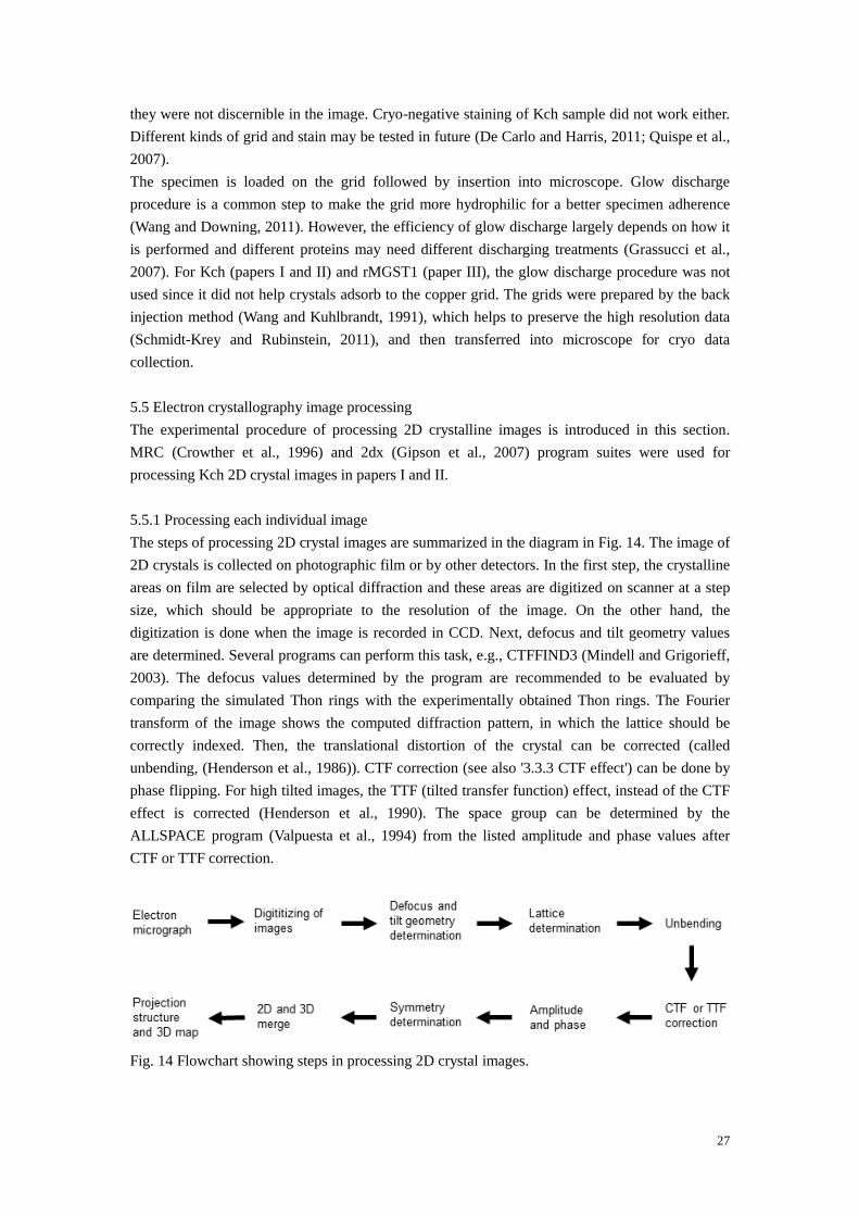
27
Fig. 14 Flowchart showing steps in processing 2D crystal images.
they were not discernible in the image. Cryo-negative staining of Kch sample did not work either.
Different kinds of grid and stain may be tested in future (De Carlo and Harris, 2011; Quispe et al.,
2007).
The specimen is loaded on the grid followed by insertion into microscope. Glow discharge
procedure is a common step to make the grid more hydrophilic for a better specimen adherence
(Wang and Downing, 2011). However, the efficiency of glow discharge largely depends on how it
is performed and different proteins may need different discharging treatments (Grassucci et al.,
2007). For Kch (papers I and II) and rMGST1 (paper III), the glow discharge procedure was not
used since it did not help crystals adsorb to the copper grid. The grids were prepared by the back
injection method (Wang and Kuhlbrandt, 1991), which helps to preserve the high resolution data
(Schmidt-Krey and Rubinstein, 2011), and then transferred into microscope for cryo data
collection.
5.5 Electron crystallography image processing
The experimental procedure of processing 2D crystalline images is introduced in this section.
MRC (Crowther et al., 1996) and 2dx (Gipson et al., 2007) program suites were used for
processing Kch 2D crystal images in papers I and II.
5.5.1 Processing each individual image
The steps of processing 2D crystal images are summarized in the diagram in Fig. 14. The image of
2D crystals is collected on photographic film or by other detectors. In the first step, the crystalline
areas on film are selected by optical diffraction and these areas are digitized on scanner at a step
size, which should be appropriate to the resolution of the image. On the other hand, the
digitization is done when the image is recorded in CCD. Next, defocus and tilt geometry values
are determined. Several programs can perform this task, e.g., CTFFIND3 (Mindell and Grigorieff,
2003). The defocus values determined by the program are recommended to be evaluated by
comparing the simulated Thon rings with the experimentally obtained Thon rings. The Fourier
transform of the image shows the computed diffraction pattern, in which the lattice should be
correctly indexed. Then, the translational distortion of the crystal can be corrected (called
unbending, (Henderson et al., 1986)). CTF correction (see also '3.3.3 CTF effect') can be done by
phase flipping. For high tilted images, the TTF (tilted transfer function) effect, instead of the CTF
effect is corrected (Henderson et al., 1990). The space group can be determined by the
ALLSPACE program (Valpuesta et al., 1994) from the listed amplitude and phase values after
CTF or TTF correction.

28
Fig. 15 Map generation in EC. (Top) The map is calculated from images only. (Bottom) The
phase information from images and the amplitude information from diffraction patterns is
combined together to generate the map. Kch is used as an example for image processing and
rMGST1 is illustrated for diffraction pattern processing.
5.5.2 Map generation
After processing all images individually, they can be merged (Figs. 14 and 15). These images are
moved to the same origin and then aligned. The processing procedure can be iteratively performed
to obtain a consistent data set. Usually, the projection structure from untilted images is generated
first. The projection structure only shows the 2D information, where the information along the
beam axis is added together. Furthermore, a 3D map can be reconstructed by inverse Fourier
transform of the structure factors of the data set including tilted images.
Since there is no periodicity in the z-direction (along the beam axis), 2D crystals show continuous
lines (called lattice lines) along this dimension in reciprocal space. The points where a central
section intersects the lattice lines are recorded (Amos et al., 1982). Once a sufficient amount of
these points are collected, a smooth curve can be adapted to generate each lattice line (Agard,
1983). The discrete points at equidistant sampling (spaced at 1/thickness) in each generated lattice
line are sinc functions interpolated from the recorded points nearby (Amos et al., 1982). Then, the
structure factors can be extracted from these discrete points and used to calculate the 3D map.
5.6 Electron diffraction processing
A structure can be reconstructed from the data consisting of pure images, or it can be obtained
from combination of phase information from images and amplitude information from diffraction
patterns (Fig. 15) (Fujiyoshi, 1998). The amplitude information calculated from diffraction
patterns is more accurate than the one from images, since the diffraction does not suffer from the
CTF effect (Amos et al., 1982).
5.6.1 Steps in electron diffraction processing
The crystal needs to be larger for electron diffraction purpose as compared to the one for image
processing (Unger, 2000). After indexing and tilt geometry determination, the intensities of the
reflection are integrated. Then various corrections of amplitudes are performed, e.g., deletion of

29
extremely strong densities from 'blooming' and subtraction of the background (Brink and Wei Tam,
1996). The listed amplitudes can be merged together and refined by the MERGEDIFF program,
where the initially determined parameters are tuned (Ceska and Henderson, 1990). The quality of
the data set is measured by Rsym (R-factor between the Friedel pairs in each diffraction pattern)
and Rmerge (R-factor between the newly added diffraction pattern and the reference) (Ceska and
Henderson, 1990). Electron diffraction patterns were collected to solve the rMGST1 structure in
paper III.
5.6.2 Common crystallographic terminology
Single sheets of 2D crystals can stack together to form the type I 3D crystal (Michel, 1983). The
basic theories shared by x-ray diffraction and electron diffraction are summarized as follows:
A). Building block
The unit cell is the smallest repeating unit to build the entire crystal by only translational
movements. A unit cell can further be divided into several asymmetric units, which can build one
unit cell by application of the space group symmetry operation, including both translational and
rotational movements.
B). Bragg diffraction
When the incident beam hits the atoms in the crystal, it scatters in all directions. Only those
fulfilling the Bragg's law (2dsinθ = nλ, where d is the distance between two crystal planes, θ is the
angle of the incident beam, n is an integer, and λ is the wavelength of the incident beam) can
constructively interfere and then a reflection is observed. Each reflection has contributions from
all atoms in every unit cell.
C). Structural determination
Both amplitude and phase information is required to calculate the protein structure. Although the
phase information can be extracted from images, the molecular replacement method used in x-ray
crystallography can also be applied in EC. Since the images are distorted by the CTF effect (see
also '3.3.3 CTF effect'), the phase information obtained from them may not be very accurate. Thus,
molecular replacement or other phase extension methods may lead to better quality results
(Wisedchaisri and Gonen, 2011). Besides that, when the structure determined in EC reaches
atomic resolutions, the differences between electron and x-ray scattering factors are small, thus the
programs for structural determination in x-ray crystallography can be used in a similar way to
process the EC data (Gonen et al., 2004; Holm et al., 2006).
5.7 Single particle reconstruction processing
SPR is most frequently used to determine the structure of complexes (particles with large
molecular weight) and nowadays, using the advanced direct detector, the reconstructed structures
can reach atomic resolutions (such as in TRPV1: EMD-5778) (see also '3.2.2 Single particle
reconstruction').
5.7.1 Steps in single particle reconstruction
Fig. 16 summarizes the main steps in SPR using Kch as an example. First of all, images are taken
from the negative staining or cryo samples. Then, the single particles in each image are picked and
stacked together, followed by CTF correction. The defocus parameters are determined by Thon
ring fitting. After combining all picked particles together, 2D classification is performed to group

30
Fig. 16 Processing of separated single particles in conventional SPR. The functional mutant,
KchM240L is used as an example to illustrate the procedure. The defocus values are determined
by Thon ring fitting using the 2dx program (right power spectrum). The class averages are
generated using EMAN2. The Kch 3D map (Lundback et al., 2009) is docked with the atomic
structures of Kv1.2 (PDB: 2A79, model in blue) and KtrA gating ring (PDB: 2HMW, model in
yellow).
them based on their individual orientations. 2D classification includes several steps in sequence: 1)
the particles are aligned to each other and centered; 2) different algorithms of classification can be
applied to the aligned particles, e.g., hierarchical ascendant or κ-means classification; and 3) the
particles in each class are averaged to generate the class average. Next, the corresponding Euler
angle is assigned to each class average by either common lines in the reference-free method or
projection matching with a reference. Then, reconstruction is done by inverse Fourier transform in
reciprocal space or back-projection in real space. The initial model can be iteratively refined by
the reprojection-classification-reconstruction cycle. The cycle is repeated until the reconstructions
no longer change and the variation of the Euler angles is below a threshold. Lastly, the external
model such as the one determined by x-ray crystallography is docked into the entire or part of the
Coulomb potential map, if the resolution of the map does not allow model building directly.
A broad spectrum of SPR programs are available at present, e.g., EMAN1 (Ludtke et al., 1999),
EMAN2 (Tang et al., 2007), Spider (Frank et al., 1996), Imagic (van Heel et al., 1996), BSoft
(Heymann, 2001), Xmipp (Sorzano et al., 2004), Sparx (Hohn et al., 2007), Frealign (Grigorieff,
2007), Relion (Scheres, 2012), and Simple (Elmlund and Elmlund, 2012). Each program has its
own algorithm and may result in different reconstructions from the same data (Murray et al.,
2013). Furthermore, different programs may have slightly modified procedures as described above.
For example, the CTF effect is corrected on reconstructions in Spider but on picked particles in
EMAN1 and EMAN2.
5.7.2 Single particle reconstruction to process two dimensional crystal images
Although normally the separated particles are analyzed in SPR and periodic arrays of unit cells are
studied in EC, the general principle of these two methods is similar. In addition, since SPR

31
determines the Euler angle for each particle, it can potentially correct for variations of tilt angle,
rotations of individual unit cells and large translational errors which are not taken into account by
EC. Therefore, SPR can be adapted to process 2D crystal images (Koeck et al., 2007; Scherer et
al., 2014). Paper IV presented such a SPR procedure developed from the previous one (Koeck et
al., 2007).
EMAN programs were used for all steps, except for CTF determination (performed by CTFFIND3)
and correction (performed by Spider). The resolution estimation is measured at the point where
the Fourier shell correlation (FSC) is at 0.5 (FSC = 0.5 criterion) (Penczek, 2010). MelBec 2D
crystal images were processed by the SPR procedure in paper IV.
Part III Results
6 Aim of investigation
Membrane proteins play important roles in all processes for living cells. Many of them have
clinical and pharmaceutical interests. The aim of this investigation is to study structure of
membrane proteins using electron microscopy in order to better understand their function. Three
proteins are analyzed: Kch (a putative K+ channel in E. coli, papers I and II), rMGST1 (a
detoxification enzyme from rat, paper III), and MelBec (a secondary transporter in E. coli, paper
IV). Apart from structural determination, a SPR procedure is developed for analysis of small or
locally distorted 2D crystals.
Specific aims in each project
1). Kch project
A). To study a K+ channel in a lipid environment
B). To identify the position of the RCK domain
C). To compare the structures obtained from EC and SPR
2). rMGST1 project
A). To refine the previously experimental procedure
B). To build a more accurate model
C). To analyze the ligand conformation
3). MelBec project
A). To accurately determine and correct the CTF effect from tilted images
B). To refine the previous SPR procedure
C). To use both EC and SPR methods to process MelBec images
7 Summary of individual papers
The experimental steps and the corresponding results are summarized as follows:
A). Protein expression, purification, and 2D crystallization
The aim of these experimental steps is to prepare the samples for data collection. These steps are
included in all projects in this thesis.
B). Projection structure determination
It is an intermediate step in image processing. The projection structure in paper I suggests a new

32
assembly of Kch.
C). 3D map generation
The 3D map is generated after calculation of the projection structure. The 3D map of the
transmembrane part of Kch (KchTM, paper II) suggests that the RCK domain is exposed to the
solvent.
D). Electron diffraction process
Electron diffraction patterns were collected from large rMGST1 2D crystals and this data was
used to determine its atomic structure in paper III.
E). Single particle reconstruction process
Besides the standard EC method, a SPR method was used to process the 2D crystal images of
MelBec in paper IV.
F). Structural determination
The Kch structure was obtained by processing 2D crystal images in paper II. The atomic structure
of rMGST1 was presented in paper III. The MelBec structure was generated by SPR in paper IV.
7.1 Papers I and II: Projection structures of KchM240L and KchTM
Kch contains 6 TMs and an RCK domain in the cytosol. The previously x-ray crystallographic
studies showed that the RCK domain forms an octameric gating ring structure in MthK (Jiang et
al., 2002a; Ye et al., 2006), BKca (Leonetti et al., 2012; Wu et al., 2010; Yuan et al., 2012; Yuan et
al., 2010), KtrA (Albright et al., 2006), and TrkA (Cao et al., 2013b). The gating ring in Kch was
observed in the previous SPR study as well (Lundback et al., 2009). However, the majority of
studies concerned isolated gating ring domains without their transmembrane parts or analyzed the
samples surrounded by detergent. Thus, it is interesting to study such a kind of channel in a lipid
environment.
Large and well-ordered 2D crystals of both KchM240L, the full-length protein (paper I), and
KchTM, which lacks the RCK domain (paper II) were obtained. KchM240L contains one point
mutation at position 240 (methionine is replaced with leucine) and is a functional mutant of Kch
(Kuo et al., 2003b). The projection structure of KchM240L was merged from the twelve best
images with Fourier components extending to 6 Å resolution (Fig. 17B) and the projection
structure of KchTM was averaged from nine images with a resolution cutoff at 8 Å (Fig. 17A).
Both crystals were assigned the c12 two-sided plane group (Supplementary Fig. S1 for
KchM240L in paper I and Figure S1 for KchTM in paper II) and the unit cell dimensions were
similar: a = 144 ± 1.9 Å, b = 84 ± 1.0 Å, γ = 90° for KchM240L (Table 1 in paper I) and a = 143 ±
0.9 Å, b = 82 ± 0.6 Å, γ = 90° for KchTM (Table 1 in paper II). As the two projection structures
resembled each other, it indicates that a similar crystal packing exists in both samples and RCK is
probably flexible thus not affecting the crystal packing.
In both projection structures, only two kinds of density zone appear which are outlined in a square
and two circles in Figs. 17A and B. The square region is where the two-fold rotation symmetry
element is situated and the circle regions are where the two-fold screw symmetry element goes
through. Based on that, we generated two different models (Supplementary Fig. S4A in paper I
and Fig. 17C) using a structurally similar K+ channel (MlotiK1, PDB: 3BEH) to overlay either of
these two distinct zones. As explained in paper I, only the model shown in Fig. 17C
(corresponding to Fig. 6C in paper I) is possible. In this model, the pore-forming domain of
MlotiK1 is centered on the circle regions and the sensor domain is on the square regions. Both

33
Fig. 17 The c12 symmetrized
projection structures of
KchTM (A) and KchM240L
(B and C). One unit cell (in a
rectangle), the two-fold
rotation symmetry elements
(full arrows), the two-fold
screw symmetry elements
(half arrows), a and b axes,
and two density zones (in a
square and two circles) are
depicted in (A and B). In (C),
Tetramers of MlotiK1 (PDB:
3BEH, each tetramer has one
color) are superimposed to the
KchM240L projection
structure (B). A temperature
factor of B = -500 Å2 was
applied to boost the fall-off of
the amplitudes at intermediate
and high resolutions in both (B
and C). The positive contours
(continuous lines) indicate the
peaks of density above the
average and the negative
contours (dashed lines) are
below the average.
KchM240L and KchTM crystallize in shifted double layers, as indicated in Fig. 17C. The
tetramers in blue, red, and magenta are in the top layer and those in yellow, cyan, and green are in
the bottom layer. The arrangement of KchM240L under the present 2D crystallization condition is
not compatible with formation of a dimer of molecules through the RCK gating ring.
7.2 Paper II: 3D structure of KchTM
Although the projection structure of KchM240L indicates that the RCK gating ring does not form
under the present 2D crystallization condition, it is not possible to determine the orientation of the

34
Fig. 18 The 3D map of KchTM with the MlotiK1 model (PDB: 3BEH). Both the complete map
(A) and the slices ((B) is in a vertical position and (C) is in a horizontal position) are shown. (A)
and (B) are visualized along the membrane plane with the intracellular side up and the
extracellular side down. (C) is viewed from the intracellular side. Only the pore-forming domain
of the model (magenta) and its corresponding map (cyan) are displayed, since there is no
convincing density of the sensor domain in the map.
channel molecules from untilted images. The proceeding study (paper II) was carried out to
analyze the 3D structure of Kch.
One computed diffraction pattern of an image of the Kch 2D crystals can be indexed in three ways.
Among them, only one alternative has a correct indexing, where the square regions (Figs. 17A and
B) in the newly added image match with the corresponding zones in the reference. The other two
alternatives compare their regions to the different zones, where the circle regions (Figs. 17A and B)
in the newly added image are aligned to the square regions in the reference, thus they should be
excluded. However, due to the similarity, but not identity, between the circle and square regions in
Fig. 17B, choosing the correct indexing in KchM240L is not obvious. This ambiguity becomes
more severe in particular for processing of tilted images. The projection structures with different
indexing in each individual image were compared and the ones in which the two-fold rotation
symmetry elements are located in the square region were considered as having a correct indexing.
Furthermore, the merging process was also judged by the phase residuals.
On the other hand, the indexing and merging of the projection images of KchTM were easier than
for KchM240L, since the two density zones were significantly different (Fig. 17A). However, the
visibility of the c12 projection symmetry disappeared when tilted images were processed, making
the choice of correct indexing less certain. Thus the strategy was purely based on choosing the
alternative that gives a significantly lower phase residual than the other two possibilities after
origin refinement. In contrast to KchM240L, a 3D map was reconstructed for KchTM.
Based on the position of the pore-forming domain as shown in Fig. 18 and adjacent molecules
imposed by the unit cell dimensions and the symmetry elements, the molecular packing in the
crystal is generated. Although KchTM does not contain an RCK domain, the position of the RCK
domain can be deduced from the KchTM crystals, since the same crystal packing exists in these
two crystals. As shown in Fig. 19, the RCK domains are exposed to the solvent and the RCK
gating ring does not form.

35
Fig. 19 Crystal packing in KchTM. The
double layered packing is visualized
along the membrane plane, the same
view in Figs. 18A and B. As it is rotated
90° from the view in Fig. 17, the
MlotiK1 tetramers in the top layer are in
blue and red while the tetramer in the
bottom layer is in yellow. The crystal
contact interfaces are boxed in a
rectangle, which includes the
pore-forming domain, the sensor
domain, and the loops between S5 and
the pore helix (gray). The RCK domains
are deduced to be located at both leaflets
of the crystal.
7.3 Paper III: A refined model of rMGST1
MGST1 was the first MAPEG member for which an atomic model was determined. This structure
was solved by EC (Holm et al., 2006). In the present work, the previous procedure was refined in
several aspects. First of all, the enzyme was previously purified from rat liver and the present
source for 2D crystallization was from the protein over-expressed in E. coli. In addition, the
crystallization parameters were adjusted. The crystals grown at the present work were isomorphic
with those obtained earlier (same unit cell parameters (a = b = 81.8 Å and γ = 120°) and the
amplitudes showed low deviation over the entire resolution range when compared). Thus the
newly collected electron diffraction data was combined to the old data. The total number of
merged electron diffraction patterns extended from 100 to 225. In the final model, all residues
were in the allowed region in the Ramachandran plot and the R factors of Rwork and Rfree were
23.6% and 22.4%, respectively. Although the resolution did not increase from the previous work,
the crystallographic statistics was improved to allow us build a more reliable model. As compared
to the previous rMGST1 model (PDB: 2H8A), there were frame shifts in both TM 3 and TM 4 in
the present model. Furthermore, more residues at the C-terminal end of TM 1 towards the
cytoplasmic side were modeled.
The final model was built from N10 (the N-terminal residue) to L151 (the C-terminal residue),
with the absence of the loop between TM 1 and TM 2 (Figs. 20A and B). Several phospholipid
molecules could be modeled as well. Three GSH molecules were built in one trimer, where each
one was situated in a similar position as in PDB: 2H8A. As shown in Figs. 20C and D, each GSH
adopts an extended conformation and is located in a pocket comprised of R38, K42, D66, and R73
from one subunit and R74, N78, Y121, Q128, N130, and R131 from a neighboring subunit in the
trimer. Arginine residues at positions 38, 74, and 131 are conserved and have been suggested to
play key roles in catalyzing the conjugation of GSH to second substrates in other MAPEG
members (Ago et al., 2007; Jegerschold et al., 2008; Martinez Molina et al., 2007; Sjogren et al.,
2013). The extended conformation of GSH in rMGST1 is unique among the MAPEG members
and resembles the one in soluble GSTs (Dirr et al., 1994).

36
Fig. 20 The refined model of rMGST1. (A) Top view from the cytoplasmic side. (B) is visualized
along the membrane plane, rotated 90° from (A). (C) and (D) Enlarged view of the boxed area in
(B). (D) is rotated 90° from (C). The residues in the GSH binding pocket (C and D) and the
phospholipid molecules (A and B) are labeled.
7.4 Paper IV: Single particle reconstruction processing of MelBec images
In order to study small or locally distorted crystals and take advantage of SPR, a processing
procedure was developed in paper IV (see also '5.7.2 Single particle reconstruction to process two
dimensional crystal images').
The images are processed in a conventional EC procedure described in '5.5 Electron
crystallography image processing' to generate the 3D map. This reconstruction can be used as the
initial model in SPR processing. Firstly, the crystalline area in each image is identified based on
the cross-correlation profiles. Secondly, the defocus parameters are determined and the CTF effect
is corrected for each image. Since different regions in the grid have different heights in
microscope when the grid is tilted, the corresponding strips in the image are corrected individually.
Thirdly, various projections are calculated from the initial model and then used to pick up the unit
cells in the image. Fourthly, the Euler angles of these cells are assigned by comparison with the
initial model. If the Euler angle distribution of the picked unit cells matches the tilt angle of the
recorded image, these cells are stacked together for reconstruction. Otherwise, they are discarded.
Fifthly, the reconstruction is built up from all picked unit cells passing the Euler angle distribution
test. Sixthly, the cycle from steps 3-5 is repeated, which reduces the bias from the initial model.
Lastly, various post-reconstruction processes are performed, such as resolution estimation and
map sharpening.

37
Fig. 21 The assessments of reconstructed MelBec using the refined SPR procedure. (A) Euler
angle distribution. The unit cells having similar Euler angles are grouped together and each class
is represented by a white dot. The brighter the dot, the more unit cells in each class. The altitude
covers 0–90° tilt angles measured from the top to the bottom. The longitude covers 0–180°
tilt-axis angles measured from the left to the right. The horizontal line marks the nominally
maximum tilt angle (45°) in data collection. (B) The resolution curve depicted in red. The
resolution is chosen at the point where the FSC equals 0.5 (labeled at the cross between two blue
lines). (C) and (D) Fitting of the MelBst map at a resolution cutoff of 13 Å (purple, surface view)
into the map obtained by the current SPR procedure (green, mesh view). The threshold values are
adjusted to keep a similar contouring level for both maps in (C and D). The views are
perpendicular to the membrane plane (C) and along the membrane plane (D).
As compared with the previously published procedure (Koeck et al., 2007), the current one was
refined in several aspects. The improvements contained several new steps, a more accurate CTF
determination and correction, an automatic unit cell picking, and adjustment of the refinement
parameters. MelBec 2D crystal images were processed with the current SPR procedure. 67.8% of
the picked unit cells have their assigned angles equal or below 45° (Fig. 21A); the resolution
based on the 'gold standard' test (Grigorieff, 2000) is 13 Å (Fig. 21B), where the split of the entire
data set into two halves is carried out before classification. Docking of the MelBst map (MelBst has
a sequence identity of 85% to MelBec (Mizushima et al., 1992)) generated from the available
atomic model (PDB: 4M64, Mol-B) suggests that MelBec in the 2D crystals adopts an open
conformation (Figs. 21C and D).

38
Part IV Discussion and Conclusion
8 Future perspectives
Multiple types of protein are analyzed in this thesis using EM. The future work for each individual
project is discussed.
8.1 Kch
It would be interesting to determine the 3D structure of the full-length Kch, which possesses both
the transmembrane part and the RCK domain. Indeed, a number of tilted images of KchM40L
have been collected and processed. However, the data did not give a reasonable reconstruction.
The failure may be due to an uncertainty in choosing correct indexing of these images. One
possible solution is to collect more tilted images with a smaller tilt angle increment. When images
collected in this way are compared to the reference, the phase residual may reflect the effect of
indexing rather than from tilting. The low tilted images (10° for instance) can be merged
proceeding from the untitled projection structure and the resulting data can be used as a reference
to search for correct indexing of 20° tilted images. This procedure can be iterated to include higher
tilted images. On the other hand, choosing correct indexing and merging KchTM images are much
more certain, since the two density zones are significantly different (Fig. 17A). Thus, it is highly
possible to reconstruct a more accurate 3D map of KchTM when more images are included.
Different crystallization parameters, e.g., detergent, lipid, pH, salt, additive, temperature, and
crystallization procedure were screened. The majority of obtained 2D crystals were of the stacked
sheets type with a few separated single sheets. Other parameters can be adjusted; one of them,
various kinds of lipid, is of a particular interest. Apart from keeping the integrity of the K+
channels (Jiang et al., 2003; Lee et al., 2005), some lipids are ligands to modulate the function of
channels (Suh and Hille, 2008). Thus, it is worth trying a mixture of lipids in crystallization. With
more separated single sheet type crystals, it is possible to analyze the specimen by shadowing or
atomic force microscopy which can provide additional information of the structure of the RCK
domain.
The physiological function of Kch could be studied more closely in the E. coli strain (TK2420)
which is defective in three major K+ ion uptake proteins: Trk/Kdp/Kup (Epstein et al., 1993).
Considering the indiscernible phenotype of the mutant strain where the kch gene is knocked out
(Epstein, 2003; Kuo et al., 2003b), harsh conditions (extreme pH and K+ concentrations in the
culture media) may be investigated (Kuo et al., 2005; Kuo et al., 2003b).
8.2 rMGST1
Although each GSH molecule in rMGST1 adopts an extended conformation, the exact
conformation, position, and orientation of GSH are not completely certain. The functional studies
have shown that rMGST1 has one-third-of-the-sites-reactivity, in which three GSH molecules can
bind to each protein trimer with their own binding affinities (Kd = 20 μM, 0.4-2.5 mM, and 2.5
mM, respectively), but only one GSH is active (Alander et al., 2009). Since the rMGST1 crystals
were grown at 1 mM GSH, it is possible that only one or two GSH binding sites among the three
sites are occupied. Thus, the GSH density would be averaged out and become weaker. One
solution is to determine the rMGST1 structure from the crystals grown at a higher GSH
concentration. The initial result showed that the isomorphic crystals could also be obtained at 5

39
mM concentration. In future, a whole data set of rMGST1 can be collected at this concentration.
Furthermore, the structural and functional studies of rMGST1 can serve as a model for analysis of
other MAPEG members. MGST2 and MPGES1 own the 'one-third-of-the-sites-reactivity'
property as well (Ahmad et al., 2013; He et al., 2011), whereas LTC4S has one active GSH in each
monomer (Ahmad et al., 2013). Another solution is to co-crystallize with an inhibitor and/or a
substrate. The experiment of co-crystallization with TNB, which results in a dead-end product (Fig.
9B), can provide the information of an intermediate step in the reaction cycle as well as result in
an easier assignment of the GSH density due to a bulk benzene ring in TNB. The initial
experiments showed that soaking the 2D crystals into the TNB solution tended to make them
fragile, although diffraction patterns have been collected from the intact ones. These TNB soaked
crystals were isomorphic with the original ones, which were grown at 1 mM GSH. The in-plane
resolution of the TNB data also extended to 3 Å. However, the data is awaiting further refinement
and interpretation.
8.3 MelBec
Docking of the available atomic structure of MelBst into the obtained map is presented in Figs.
21C and D. Considering the inner symmetry of the transporter (Fig. 11A) and many intermediate
steps in the entire reaction cycle (Fig. 10), it is worth trying to test docking of the models in
different conformations. A number of structures crystallized in various conformations (different
states, with or without ligand) from related MFS members are available now. Thus, homology
modeling using these structures as the templates (see also '2.4 Computational modeling') may
improve the docking efficiency and give further information of transition between different states.
It would also be interesting to grow 2D crystals without sugar. By combination of the apo data
(without ligand) and the data with sugar (paper IV), it is possible to demonstrate the
conformational change after sugar binding. The MelBec structures can be further compared with
the LacY structures (lactose permease of E. coli, homologue to MelBec, (Yousef and Guan, 2009))
with (PDB: 4OAA, (Kumar et al., 2014)) and without (PDB: 2CFQ, (Mirza et al., 2006)) ligand.
The developed SPR method can be applied to process the apo data. The reconstruction obtained
from the sugar data in paper IV is possible to be used as the initial model for unit cell picking from
the apo data. Low-pass filtering of the initial model may help to reduce the basis from the sugar
data.
8.4 Single particle reconstruction processing of two dimensional crystal images
The developed SPR procedure is semi-automated; commands are typed to run the scripts in each
step. However, these commands are not based on the choices of users. Therefore, the SPR
procedure can be improved to be fully automated in future.
This SPR procedure is aimed for small or locally distorted crystals. Since testing each
crystallization condition consumes approximately 40 μl concentrated samples in a conventional
dialysis experiment in the beaker (microdialysis uses less materials, however the result may be
less reproducible), the total number of screened conditions is normally not very large. Thus, many
resulting crystals are small and the resolutions of them remain around 10 Å. The 2D crystal of
Na+,K
+-ATPase from pig kidney (a primary transporter moves K
+ and Na
+ ions in opposite
directions across the plasma membrane) is such a case. The small crystals usually contain 300-500
unit cells (0.2 μm, (Hebert et al., 2001)), thus they are suitable to be evaluated by the SPR method.

40
A potential benefit of using the SPR procedure is to include unmerged images in EC. Therefore,
application of this method to process the KchM240L and KchTM images can avoid the indexing
problem and the resulting reconstruction is expected to be less affected by personal judgments.
rMGST1 is also an interesting data to be tested. Previous studies showed that rMGST1 purified
from rat liver could crystallize in two ways: p6 and p21212 two-sided plane group symmetries
(Schmidt-Krey et al., 1998). The 3D maps reconstructed from both crystals reached 3.5 Å (Holm
et al., 2006). However, due to a higher symmetry and completeness in the p6 type, the structure of
rMGST1 was determined from the p6 type crystals whereas the p21212 data was used as an
independent control (Holm et al., 2006). On the other hand, the number of p21212 type images was
more than the p6 type ones (Holm et al., 2006). Thus, the developed SPR method could be applied
to the p21212 type images to validate whether it works for a near atomic resolution data or not.
Furthermore, it is possible to distinguish the bound GSH molecules in multiple conformations
from both data sets using the SPR method.
8.5 Future of electron microscopy
Until now, x-ray crystallography is the main method to determine a protein's structure. However, it
still demands suitable well-ordered 3D crystals for data collection, which might be difficult. On
the other hand, NMR has a limitation on the size of the analyzed sample. EM is a powerful tool
suitable for a broad range of specimens which are generally easier to be prepared as compared to
the specimens for x-ray crystallography.
The great advantage of EM is that phase information can be extracted from an image, whereas
additional work is required to get the phase information in x-ray crystallography. MPs are suitable
for EC, where they are embedded in more natural lipid environments. Lipid environment plays
critical roles at least in some proteins (Zhou and Cross, 2013). Although EC still requires
repeating work and is a slow process as compared to the other methods, automation is expected to
improve the speed and success of each project (Hu et al., 2010; Iacovache et al., 2010;
Wisedchaisri et al., 2011). In cells, MPs are often assembled together to form protein complexes
(Alberts, 1998). These super-complexes are of central importance for cellular function and they
are ideal targets to be studied by SPR, e.g., COX2/MPGES1 (Yamagata et al., 2001) and
BKca/voltage gated calcium channels (Berkefeld et al., 2006). On the other hand, SPR faces the
problem of processing low signal-to-noise ratio images. However, with the development of
modern electron microscopes, in particular the direct detectors, and processing software,
biological samples can reach near atomic resolutions in EM now, which could be obtained only in
x-ray crystallography in the past. Another advent is to combine fluorescence microscopy and EM
together, which provides both the functional and structural views of the protein of interest in its
environment (Agronskaia et al., 2008).
9 Conclusion
The structure of three MPs: Kch, rMGST1, and MelBec are studied in this thesis. For this, EC is
mainly used. In addition, a SPR procedure is developed to process 2D crystal images.
For the Kch project, large and well-ordered 2D crystals were grown for both the full-length
protein (KchM240L, a functional mutant of Kch) and the channel containing only the
transmembrane part (KchTM, lacking the RCK domain at the C-terminus). The projection
structure of KchM240L was calculated at 6 Å resolution and 8 Å for KchTM. These two

41
projection structures resemble each other, indicating a similar crystal packing in both cases. The
superimposing of a structurally comparable atomic model of a K+ channel showed that Kch
crystallizes as two symmetry-related overlapping layers. The determined 3D map of KchTM
showed that the crystal contacts are from the extracellular surfaces of the protein. Thus, the RCK
domain in the intracellular side of Kch is exposed to solvent. This conclusion stands in contrast to
previous studies which predicted that the RCK domains interact to form an octameric gating ring
structure. The discrepancy between the current electron crystallographic and previously structural
studies, including the x-ray crystallographic and single particle reconstruction ones, probably
reflects the important effect of lipid environment on MPs.
rMGST1 was over-expressed in E. coli and the 2D crystallization condition was adjusted as
compared to the previous protocol. In contrast to the previous result, only the p6 two-sided plane
group symmetry crystals were detected. The refined structure was determined from 225 diffraction
patterns and calculated at 3.5 Å. The new model contains 123 out of 155 amino acid residues, two
structured phospholipid molecules, two hydrocarbon chains, and one GSH molecule. Compared
with the previously determined model (PDB: 2H8A), the present one extends the region at the
C-terminal end of TM 1 and corrects the frame shifts in both TM 3 and TM 4. Two phospholipid
molecules glue two adjacent protein trimers together. In addition, one hydrocarbon chain is
located at the crystallographic symmetry axis and the other is between TM 1 and TM 3 on the
cytoplasmic side. In contrast to other MAPEG members, the GSH molecules bind in an extended
conformation at the interfaces between two subunits of the trimer. Each GSH is located in a pocket
comprised of R38, K42, D66, and R73 from one subunit and R74, N78, Y121, Q128, N130, and
R131 from a neighboring subunit in the trimer. The location of GSH is supported by the
mutagenesis data in vitro.
A refined SPR procedure for processing of 2D crystal images was developed. This method
combines the advantage of both SPR and EC. It is aimed at processing images of MPs that form
small or locally distorted 2D crystals. The reconstruction obtained from EC is used as the initial
model to pick up similar unit cells based on the cross-correlation profiles. The picked unit cells in
each image are analyzed by their respective Euler angle distributions to sort out the ones which do
not match their expected tilt angles. The reconstruction is calculated from the newly picked unit
cells and the resulting map serves as an initial model to repeat the entire procedure in order to
reduce the model bias in the first run. Other improvements include a strip based CTF
determination and correction, adjustment of the refinement parameters, and several refined
post-reconstruction processes. The tested data, MelBec showed that a reliable reconstruction was
obtained at 13 Å resolution (based on the 'gold standard' test). The docking of the atomic structure
of MelB from another species into the final map indicated that MelBec adopts an open
conformation under the present 2D crystallization condition.
Part V Epilogue
10 Acknowledgements
The work was financed by the Swedish Research Council and the Karolinska Institutet Center for
Innovative Medicine. Many thanks to the Department of Biosciences and Nutrition, Karolinska
Institutet and School of Technology and Health, Royal Institute of Technology supporting me to
carry out the investigation in my Ph.D. study. I would like to express to my gratitude to my

42
colleagues, family, and friends who have helped me complete the work.
First of all, my supervisor Hans Hebert, for accepting me in your group, for giving me the
opportunity to work with EM, and for many supports in all aspects. My supervisor Caroline
Jegerschöld, for your endless enthusiasm in science and never giving up spirit. My supervisor
Per-Johan Jakobsson, for assisting me at the beginning of my study and the guidance in the
MAPEG project.
Current members in Hans Hebert's group:
Pasi Purhonen, for your help in data collection and translating Swedish letters for me.
Philip Koeck, for explaining SPR knowledge.
Martin Lindahl, for your teaching the EM course and discussing about the projects.
Johan Härmark, for making the website for the group and introducing the Swedish society.
Harriet Nilsson, for your encouragement all the time.
Ramakrishnan Balakrishnan Kumar, for sharing your experimental technology and showing me
how to work with yeast.
Lin Zhu, for your concern about my life and discussion about the projects.
Rampradeep Samiappan, for your good mood and inviting me to play cricket.
Many thanks to the previous members: Kimberley Cheng, Anna-Karin Lundbäck, Hans Elmlund,
Dominika Elmlund, and Peter Holm. Special thanks to Thirupathi Pattipaka, for writing the script
to pick up the unit cells automatically and Yohannes Haileyesus Ayele, for guiding me in
processing crystal images and discussing the problems you met.
Colleagues in STH, KTH:
Xiaogai Li, for inviting me to your apartment and cooking delicious food. Also thanks for the
concern from you and your husband, Weidong Lian.
Sicong Yu, for your help in my routine life and sharing working experiences with me.
Eva-Rut Lindberg and Fredrik Häggström, for handling the academic documents.
Current members in Department of Biosciences and Nutrition, KI:
Sharif Hasni, for sharing your life experience in UK.
Min Jia, Zhiqiang Huang, Ning Liang, Jian Zhu, Ting Zhuang, Miao Zhao, Xiaowei Gong, Zhilun
Li, Mathilda Sjöberg, You Xu, Erik Lundgren, Anders Lindholm, Punit Prasad, and Kashyap Dave
for a nice atmosphere.
Previous members in Department of Biosciences and Nutrition, KI:
Xiaohua Lou, for teaching me how to use the AKTA machine and the knowledge of x-ray
crystallography.
Wei Liu, for answering my questions in x-ray crystallography and providing technical assistance
during my study. Also thanks to your wife, Jun Wang for her optimistic attitude.
Shangrung Wu, for assisting me to use electron microscope and discussing SPR.
Chiounan Shiue, for your introduction of the Swedish society and the situation in Taiwan.
Colleagues in other departments, KI:
Ralf Morgenstern, for your guidance, support, and effort in the rMGST1 project.

43
Johan Ålander, for showing me how to express and purify rMGST1 at the beginning of my study.
Linda Spahiu, for organizing the MAPEG meeting in Djurönäset.
Sven-Christian Pawelzik, for instructing me how to do science in an efficient and organized way.
Serhiy Souchelnytskyi, for helping me to use mass spectrometry.
Christina Hebert, for inviting me to your house and delicious Swedish salmon.
Sylvie-Le Guyader, for maintainance of the fluorescence microscope and organizing the cookie
club.
Pablo-Hernandez Varas, for generously sharing me the protocol and materials for protein labeling.
Anna Magnusson, for your guidance in the preliminary experiment of working with rat, for your
kind invitation to your house, and for your positive attitude.
Colleagues in other universities:
Richard Armstrong, for your many times discussion about the rMGST1 structure and H/D
exchange experiments.
Lin Zhu, for your introduction of the situation in China and suggestions for my future.
Henning Stahlberg, for organizing the 2dx workshop and your active discussion in the EM
community.
Sanjeewani Sooriyaarachchi, for being a good friend and always encouraging me.
Wimal ubhayaseker, for helping me in the rMGST1 project and encouraging me to work with EM.
Adrian Suarez Covarrubias, for telling me the job opportunities and assisting me in expression and
purification when I started to perform experiments.
Lars Liljas, for your concern all the time and introducing me to the structural study.
My parents:
Chengbu Kuang, for your care and love, always listening to me, and encouraging me to start my
Ph.D. study in Sweden.
Kang Li, for you concern and guidance, reminding me things which I forgot, and supporting me
during my entire life.
Also many thanks to my other relatives, friends, and colleagues, who are not mentioned due to the
limited space in this acknowledgements.

44
11 References
Adrian, M., Dubochet, J., Fuller, S.D., and Harris, J.R. (1998). Cryo-negative staining. Micron 29,
145-160.
Agard, D.A. (1983). A least-squares method for determining structure factors in three-dimensional
tilted-view reconstructions. J. Mol. Biol. 167, 849-852.
Aggarwal, S.K., and MacKinnon, R. (1996). Contribution of the S4 segment to gating charge in
the Shaker K+ channel. Neuron 16, 1169-1177.
Ago, H., Kanaoka, Y., Irikura, D., Lam, B.K., Shimamura, T., Austen, K.F., and Miyano, M.
(2007). Crystal structure of a human membrane protein involved in cysteinyl leukotriene
biosynthesis. Nature 448, 609-612.
Agronskaia, A.V., Valentijn, J.A., van Driel, L.F., Schneijdenberg, C.T., Humbel, B.M., van
Bergen en Henegouwen, P.M., Verkleij, A.J., Koster, A.J., and Gerritsen, H.C. (2008). Integrated
fluorescence and transmission electron microscopy. J. Struct. Biol. 164, 183-189.
Ahmad, S., Niegowski, D., Wetterholm, A., Haeggstrom, J.Z., Morgenstern, R., and
Rinaldo-Matthis, A. (2013). Catalytic characterization of human microsomal glutathione
S-transferase 2: identification of rate-limiting steps. Biochemistry (Mosc). 52, 1755-1764.
Alam, A., and Jiang, Y. (2011). Structural studies of ion selectivity in tetrameric cation channels. J.
Gen. Physiol. 137, 397-403.
Alander, J., Lengqvist, J., Holm, P.J., Svensson, R., Gerbaux, P., Heuvel, R.H., Hebert, H.,
Griffiths, W.J., Armstrong, R.N., and Morgenstern, R. (2009). Microsomal glutathione transferase
1 exhibits one-third-of-the-sites-reactivity towards glutathione. Arch. Biochem. Biophys. 487,
42-48.
Alberts, B. (1998). The cell as a collection of protein machines: preparing the next generation of
molecular biologists. Cell 92, 291-294.
Albright, R.A., Ibar, J.L., Kim, C.U., Gruner, S.M., and Morais-Cabral, J.H. (2006). The RCK
domain of the KtrAB K+ transporter: multiple conformations of an octameric ring. Cell 126,
1147-1159.
Allegretti, M., Mills, D.J., McMullan, G., Kuhlbrandt, W., and Vonck, J. (2014). Atomic model of
the F420-reducing [NiFe] hydrogenase by electron cryo-microscopy using a direct electron
detector. eLife 3, e01963.
Amos, L.A., Henderson, R., and Unwin, P.N. (1982). Three-dimensional structure determination
by electron microscopy of two-dimensional crystals. Prog. Biophys. Mol. Biol. 39, 183-231.
Amunts, A., Brown, A., Bai, X.C., Llacer, J.L., Hussain, T., Emsley, P., Long, F., Murshudov, G.,
Scheres, S.H., and Ramakrishnan, V. (2014). Structure of the yeast mitochondrial large ribosomal
subunit. Science 343, 1485-1489.
Anfinsen, C.B. (1973). Principles that govern the folding of protein chains. Science 181, 223-230.
Berkefeld, H., Sailer, C.A., Bildl, W., Rohde, V., Thumfart, J.O., Eble, S., Klugbauer, N.,
Reisinger, E., Bischofberger, J., Oliver, D., et al. (2006). BKCa-Cav channel complexes mediate
rapid and localized Ca2+-activated K+ signaling. Science 314, 615-620.
Bresell, A., Weinander, R., Lundqvist, G., Raza, H., Shimoji, M., Sun, T.H., Balk, L., Wiklund, R.,
Eriksson, J., Jansson, C., et al. (2005). Bioinformatic and enzymatic characterization of the
MAPEG superfamily. FEBS J. 272, 1688-1703.
Brink, J., and Wei Tam, M. (1996). Processing of electron diffraction patterns acquired on a
slow-scan CCD camera. J. Struct. Biol. 116, 144-149.

45
Brohawn, S.G., del Marmol, J., and MacKinnon, R. (2012). Crystal structure of the human K2P
TRAAK, a lipid- and mechano-sensitive K+ ion channel. Science 335, 436-441.
Buckingham, S.D., Kidd, J.F., Law, R.J., Franks, C.J., and Sattelle, D.B. (2005). Structure and
function of two-pore-domain K+ channels: contributions from genetic model organisms. Trends
Pharmacol. Sci. 26, 361-367.
Butterwick, J.A., and MacKinnon, R. (2010). Solution structure and phospholipid interactions of
the isolated voltage-sensor domain from KvAP. J. Mol. Biol. 403, 591-606.
Cao, E., Liao, M., Cheng, Y., and Julius, D. (2013a). TRPV1 structures in distinct conformations
reveal activation mechanisms. Nature 504, 113-118.
Cao, Y., Pan, Y., Huang, H., Jin, X., Levin, E.J., Kloss, B., and Zhou, M. (2013b). Gating of the
TrkH ion channel by its associated RCK protein TrkA. Nature 496, 317-322.
Catterall, W.A. (2010a). Ion channel voltage sensors: structure, function, and pathophysiology.
Neuron 67, 915-928.
Catterall, W.A. (2010b). Signaling complexes of voltage-gated sodium and calcium channels.
Neurosci. Lett. 486, 107-116.
Ceska, T.A., and Henderson, R. (1990). Analysis of high-resolution electron diffraction patterns
from purple membrane labelled with heavy-atoms. J. Mol. Biol. 213, 539-560.
Chen, X., Wang, Q., Ni, F., and Ma, J. (2010). Structure of the full-length Shaker potassium
channel Kv1.2 by normal-mode-based X-ray crystallographic refinement. Proc. Natl. Acad. Sci. U.
S. A. 107, 11352-11357.
Cheng, W.W., McCoy, J.G., Thompson, A.N., Nichols, C.G., and Nimigean, C.M. (2011).
Mechanism for selectivity-inactivation coupling in KcsA potassium channels. Proc. Natl. Acad.
Sci. U. S. A. 108, 5272-5277.
Chiu, W. (1993). What does electron cryomicroscopy provide that X-ray crystallography and
NMR spectroscopy cannot? Annu. Rev. Biophys. Biomol. Struct. 22, 233-255.
Clayton, G.M., Altieri, S., Heginbotham, L., Unger, V.M., and Morais-Cabral, J.H. (2008).
Structure of the transmembrane regions of a bacterial cyclic nucleotide-regulated channel. Proc.
Natl. Acad. Sci. U. S. A. 105, 1511-1515.
Clayton, G.M., Silverman, W.R., Heginbotham, L., and Morais-Cabral, J.H. (2004). Structural
basis of ligand activation in a cyclic nucleotide regulated potassium channel. Cell 119, 615-627.
Cordero-Morales, J.F., Cuello, L.G., Zhao, Y., Jogini, V., Cortes, D.M., Roux, B., and Perozo, E.
(2006). Molecular determinants of gating at the potassium-channel selectivity filter. Nat. Struct.
Mol. Biol. 13, 311-318.
Crowther, R.A., Henderson, R., and Smith, J.M. (1996). MRC image processing programs. J.
Struct. Biol. 116, 9-16.
Cuello, L.G., Jogini, V., Cortes, D.M., and Perozo, E. (2010). Structural mechanism of C-type
inactivation in K(+) channels. Nature 466, 203-208.
De Carlo, S., and Harris, J.R. (2011). Negative staining and cryo-negative staining of
macromolecules and viruses for TEM. Micron 42, 117-131.
De Rosier, D.J., and Klug, A. (1968). Reconstruction of three dimensional structures from electron
micrographs. Nature 217, 130-134.
De Zorzi, R., Nicholson, W.V., Guigner, J.M., Erne-Brand, F., and Venien-Bryan, C. (2013).
Growth of large and highly ordered 2D crystals of a K(+) channel, structural role of lipidic
environment. Biophys. J. 105, 398-408.
46
Deisenhofer, J., Epp, O., Miki, K., Huber, R., and Michel, H. (1985). Structure of the protein
subunits in the photosynthetic reaction centre of Rhodopseudomonas viridis at 3A resolution.
Nature 318, 618-624.
Derewenda, Z.S. (2004). The use of recombinant methods and molecular engineering in protein
crystallization. Methods 34, 354-363.
Dirr, H., Reinemer, P., and Huber, R. (1994). X-ray crystal structures of cytosolic glutathione
S-transferases. Implications for protein architecture, substrate recognition and catalytic function.
Eur. J. Biochem. 220, 645-661.
Doyle, D.A., Morais Cabral, J., Pfuetzner, R.A., Kuo, A., Gulbis, J.M., Cohen, S.L., Chait, B.T.,
and MacKinnon, R. (1998). The structure of the potassium channel: molecular basis of K+
conduction and selectivity. Science 280, 69-77.
Drews, J. (2000). Drug discovery: a historical perspective. Science 287, 1960-1964.
Dubochet, J., Adrian, M., Chang, J.J., Homo, J.C., Lepault, J., McDowall, A.W., and Schultz, P.
(1988). Cryo-electron microscopy of vitrified specimens. Q. Rev. Biophys. 21, 129-228.
Elmlund, D., and Elmlund, H. (2012). SIMPLE: Software for ab initio reconstruction of
heterogeneous single-particles. J. Struct. Biol. 180, 420-427.
Engelman, D.M. (2005). Membranes are more mosaic than fluid. Nature 438, 578-580.
Epstein, W. (2003). The roles and regulation of potassium in bacteria. Prog. Nucleic Acid Res.
Mol. Biol. 75, 293-320.
Epstein, W., Buurman, E., McLaggan, D., and Naprstek, J. (1993). Multiple mechanisms, roles
and controls of K+ transport in Escherichia coli. Biochem. Soc. Trans. 21, 1006-1010.
Ethayathulla, A.S., Yousef, M.S., Amin, A., Leblanc, G., Kaback, H.R., and Guan, L. (2014).
Structure-based mechanism for Na(+)/melibiose symport by MelB. Nat. Commun. 5, 3009.
Evans, J.F., Ferguson, A.D., Mosley, R.T., and Hutchinson, J.H. (2008). What's all the FLAP
about?: 5-lipoxygenase-activating protein inhibitors for inflammatory diseases. Trends Pharmacol.
Sci. 29, 72-78.
Faruqi, A.R., and Henderson, R. (2007). Electronic detectors for electron microscopy. Curr. Opin.
Struct. Biol. 17, 549-555.
Faruqi, A.R., and McMullan, G. (2011). Electronic detectors for electron microscopy. Q. Rev.
Biophys. 44, 357-390.
Ferguson, A.D., McKeever, B.M., Xu, S., Wisniewski, D., Miller, D.K., Yamin, T.T., Spencer,
R.H., Chu, L., Ujjainwalla, F., Cunningham, B.R., et al. (2007). Crystal structure of
inhibitor-bound human 5-lipoxygenase-activating protein. Science 317, 510-512.
Ford, R.C., and Holzenburg, A. (2008). Electron crystallography of biomolecules: mysterious
membranes and missing cones. Trends Biochem. Sci. 33, 38-43.
Frank, J., Radermacher, M., Penczek, P., Zhu, J., Li, Y., Ladjadj, M., and Leith, A. (1996).
SPIDER and WEB: processing and visualization of images in 3D electron microscopy and related
fields. J. Struct. Biol. 116, 190-199.
Fujiyoshi, Y. (1998). The structural study of membrane proteins by electron crystallography. Adv.
Biophys. 35, 25-80.
Funk, C.D. (2001). Prostaglandins and leukotrienes: advances in eicosanoid biology. Science 294,
1871-1875.
Gadsby, D.C. (2009). Ion channels versus ion pumps: the principal difference, in principle. Nat.
Rev. Mol. Cell Biol. 10, 344-352.

47
Garavito, R.M., and Ferguson-Miller, S. (2001). Detergents as tools in membrane biochemistry. J.
Biol. Chem. 276, 32403-32406.
Gipson, B., Zeng, X., Zhang, Z.Y., and Stahlberg, H. (2007). 2dx--user-friendly image processing
for 2D crystals. J. Struct. Biol. 157, 64-72.
Gonen, T., Cheng, Y., Sliz, P., Hiroaki, Y., Fujiyoshi, Y., Harrison, S.C., and Walz, T. (2005).
Lipid-protein interactions in double-layered two-dimensional AQP0 crystals. Nature 438, 633-638.
Gonen, T., Sliz, P., Kistler, J., Cheng, Y., and Walz, T. (2004). Aquaporin-0 membrane junctions
reveal the structure of a closed water pore. Nature 429, 193-197.
Grassucci, R.A., Taylor, D.J., and Frank, J. (2007). Preparation of macromolecular complexes for
cryo-electron microscopy. Nat. Protoc. 2, 3239-3246.
Grigorieff, N. (2000). Resolution measurement in structures derived from single particles. Acta
Crystallogr. D: Biol. Crystallogr. 56, 1270-1277.
Grigorieff, N. (2007). FREALIGN: high-resolution refinement of single particle structures. J.
Struct. Biol. 157, 117-125.
Guan, L., Nurva, S., and Ankeshwarapu, S.P. (2011). Mechanism of melibiose/cation symport of
the melibiose permease of Salmonella typhimurium. J. Biol. Chem. 286, 6367-6374.
Hacksell, I., Rigaud, J.L., Purhonen, P., Pourcher, T., Hebert, H., and Leblanc, G. (2002).
Projection structure at 8 A resolution of the melibiose permease, an Na-sugar co-transporter from
Escherichia coli. EMBO J. 21, 3569-3574.
Hammarberg, T., Hamberg, M., Wetterholm, A., Hansson, H., Samuelsson, B., and Haeggstrom,
J.Z. (2009). Mutation of a critical arginine in microsomal prostaglandin E synthase-1 shifts the
isomerase activity to a reductase activity that converts prostaglandin H2 into prostaglandin
F2alpha. J. Biol. Chem. 284, 301-305.
Hayes, J.D., Flanagan, J.U., and Jowsey, I.R. (2005). Glutathione transferases. Annu. Rev.
Pharmacol. Toxicol. 45, 51-88.
He, S., Wu, Y., Yu, D., and Lai, L. (2011). Microsomal prostaglandin E synthase-1 exhibits
one-third-of-the-sites reactivity. Biochem. J. 440, 13-21.
Hebert, H., and Jegerschold, C. (2007). The structure of membrane associated proteins in
eicosanoid and glutathione metabolism as determined by electron crystallography. Curr. Opin.
Struct. Biol. 17, 396-404.
Hebert, H., Purhonen, P., Vorum, H., Thomsen, K., and Maunsbach, A.B. (2001).
Three-dimensional structure of renal Na,K-ATPase from cryo-electron microscopy of
two-dimensional crystals. J. Mol. Biol. 314, 479-494.
Henderson, R. (1995). The potential and limitations of neutrons, electrons and X-rays for atomic
resolution microscopy of unstained biological molecules. Q. Rev. Biophys. 28, 171-193.
Henderson, R., Baldwin, J.M., Ceska, T.A., Zemlin, F., Beckmann, E., and Downing, K.H. (1990).
Model for the structure of bacteriorhodopsin based on high-resolution electron cryo-microscopy. J.
Mol. Biol. 213, 899-929.
Henderson, R., Baldwin, J.M., Downing, K.H., Lepault, J., and Zemlin, F. (1986). Structure of
Purple Membrane from Halobacterium-Halobium - Recording, Measurement and Evaluation of
Electron-Micrographs at 3.5 a Resolution. Ultramicroscopy 19, 147-178.
Henderson, R., and Unwin, P.N. (1975). Three-dimensional model of purple membrane obtained
by electron microscopy. Nature 257, 28-32.
Heymann, J.B. (2001). Bsoft: image and molecular processing in electron microscopy. J. Struct.

48
Biol. 133, 156-169.
Hibino, H., Inanobe, A., Furutani, K., Murakami, S., Findlay, I., and Kurachi, Y. (2010). Inwardly
rectifying potassium channels: their structure, function, and physiological roles. Physiol. Rev. 90,
291-366.
Hirai, T., Murata, K., Mitsuoka, K., Kimura, Y., and Fujiyoshi, Y. (1999). Trehalose embedding
technique for high-resolution electron crystallography: application to structural study on
bacteriorhodopsin. J. Electron Microsc. (Tokyo). 48, 653-658.
Hohmann-Marriott, M.F., Sousa, A.A., Azari, A.A., Glushakova, S., Zhang, G., Zimmerberg, J.,
and Leapman, R.D. (2009). Nanoscale 3D cellular imaging by axial scanning transmission
electron tomography. Nat. Methods 6, 729-731.
Hohn, M., Tang, G., Goodyear, G., Baldwin, P.R., Huang, Z., Penczek, P.A., Yang, C., Glaeser,
R.M., Adams, P.D., and Ludtke, S.J. (2007). SPARX, a new environment for Cryo-EM image
processing. J. Struct. Biol. 157, 47-55.
Holm, P.J., Bhakat, P., Jegerschold, C., Gyobu, N., Mitsuoka, K., Fujiyoshi, Y., Morgenstern, R.,
and Hebert, H. (2006). Structural basis for detoxification and oxidative stress protection in
membranes. J. Mol. Biol. 360, 934-945.
Hu, M., Vink, M., Kim, C., Derr, K., Koss, J., D'Amico, K., Cheng, A., Pulokas, J.,
Ubarretxena-Belandia, I., and Stokes, D. (2010). Automated electron microscopy for evaluating
two-dimensional crystallization of membrane proteins. J. Struct. Biol. 171, 102-110.
Huang, B., Bates, M., and Zhuang, X. (2009). Super-resolution fluorescence microscopy. Annu.
Rev. Biochem. 78, 993-1016.
Hunte, C. (2005). Specific protein-lipid interactions in membrane proteins. Biochem. Soc. Trans.
33, 938-942.
Iacovache, I., Biasini, M., Kowal, J., Kukulski, W., Chami, M., van der Goot, F.G., Engel, A., and
Remigy, H.W. (2010). The 2DX robot: a membrane protein 2D crystallization Swiss Army knife. J.
Struct. Biol. 169, 370-378.
Imai, S., Osawa, M., Takeuchi, K., and Shimada, I. (2010). Structural basis underlying the dual
gate properties of KcsA. Proc. Natl. Acad. Sci. U. S. A. 107, 6216-6221.
Jakobsson, P.J., Mancini, J.A., and Ford-Hutchinson, A.W. (1996). Identification and
characterization of a novel human microsomal glutathione S-transferase with leukotriene C4
synthase activity and significant sequence identity to 5-lipoxygenase-activating protein and
leukotriene C4 synthase. J. Biol. Chem. 271, 22203-22210.
Jakobsson, P.J., Mancini, J.A., Riendeau, D., and Ford-Hutchinson, A.W. (1997). Identification
and characterization of a novel microsomal enzyme with glutathione-dependent transferase and
peroxidase activities. J. Biol. Chem. 272, 22934-22939.
Jakobsson, P.J., Morgenstern, R., Mancini, J., Ford-Hutchinson, A., and Persson, B. (1999).
Common structural features of MAPEG -- a widespread superfamily of membrane associated
proteins with highly divergent functions in eicosanoid and glutathione metabolism. Protein Sci. 8,
689-692.
Jardetzky, O. (1966). Simple allosteric model for membrane pumps. Nature 211, 969-970.
Jegerschold, C., Pawelzik, S.C., Purhonen, P., Bhakat, P., Gheorghe, K.R., Gyobu, N., Mitsuoka,
K., Morgenstern, R., Jakobsson, P.J., and Hebert, H. (2008). Structural basis for induced formation
of the inflammatory mediator prostaglandin E2. Proc. Natl. Acad. Sci. U. S. A. 105, 11110-11115.
Jiang, Y., Lee, A., Chen, J., Cadene, M., Chait, B.T., and MacKinnon, R. (2002a). Crystal structure

49
and mechanism of a calcium-gated potassium channel. Nature 417, 515-522.
Jiang, Y., Lee, A., Chen, J., Cadene, M., Chait, B.T., and MacKinnon, R. (2002b). The open pore
conformation of potassium channels. Nature 417, 523-526.
Jiang, Y., Lee, A., Chen, J., Ruta, V., Cadene, M., Chait, B.T., and MacKinnon, R. (2003). X-ray
structure of a voltage-dependent K+ channel. Nature 423, 33-41.
Jiang, Y., Pico, A., Cadene, M., Chait, B.T., and MacKinnon, R. (2001). Structure of the RCK
domain from the E. coli K+ channel and demonstration of its presence in the human BK channel.
Neuron 29, 593-601.
Jorgensen, P.L. (1988). Purification of Na+,K+-ATPase: enzyme sources, preparative problems,
and preparation from mammalian kidney. Methods Enzymol. 156, 29-43.
Kefala, G., Kwiatkowski, W., Esquivies, L., Maslennikov, I., and Choe, S. (2007). Application of
Mistic to improving the expression and membrane integration of histidine kinase receptors from
Escherichia coli. J. Struct. Funct. Genomics 8, 167-172.
Kendrew, J.C., Bodo, G., Dintzis, H.M., Parrish, R.G., Wyckoff, H., and Phillips, D.C. (1958). A
three-dimensional model of the myoglobin molecule obtained by x-ray analysis. Nature 181,
662-666.
Killian, J.A. (1998). Hydrophobic mismatch between proteins and lipids in membranes. Biochim.
Biophys. Acta 1376, 401-415.
Kitts, E.I., Jr. (1996). Physics and chemistry of film and processing. Radiographics 16, 1467-1479;
quiz 1464-1465.
Knapek, E., and Dubochet, J. (1980). Beam damage to organic material is considerably reduced in
cryo-electron microscopy. J. Mol. Biol. 141, 147-161.
Koeck, P.J.B., Purhonen, P., Alvang, R., Grundberg, B., and Hebert, H. (2007). Single particle
refinement in electron crystallography: a pilot study. J. Struct. Biol. 160, 344-352.
Kuhlbrandt, W. (1992). Two-dimensional crystallization of membrane proteins. Q. Rev. Biophys.
25, 1-49.
Kuhlbrandt, W., Wang, D.N., and Fujiyoshi, Y. (1994). Atomic model of plant light-harvesting
complex by electron crystallography. Nature 367, 614-621.
Kumar, H., Kasho, V., Smirnova, I., Finer-Moore, J.S., Kaback, H.R., and Stroud, R.M. (2014).
Structure of sugar-bound LacY. Proc. Natl. Acad. Sci. U. S. A. 111, 1784-1788.
Kuo, A., Gulbis, J.M., Antcliff, J.F., Rahman, T., Lowe, E.D., Zimmer, J., Cuthbertson, J., Ashcroft,
F.M., Ezaki, T., and Doyle, D.A. (2003a). Crystal structure of the potassium channel KirBac1.1 in
the closed state. Science 300, 1922-1926.
Kuo, M.M., Haynes, W.J., Loukin, S.H., Kung, C., and Saimi, Y. (2005). Prokaryotic K(+)
channels: from crystal structures to diversity. FEMS Microbiol. Rev. 29, 961-985.
Kuo, M.M., Saimi, Y., and Kung, C. (2003b). Gain-of-function mutations indicate that Escherichia
coli Kch forms a functional K+ conduit in vivo. EMBO J. 22, 4049-4058.
Law, C.J., Maloney, P.C., and Wang, D.N. (2008). Ins and outs of major facilitator superfamily
antiporters. Annu. Rev. Microbiol. 62, 289-305.
Lee, S.Y., Lee, A., Chen, J., and MacKinnon, R. (2005). Structure of the KvAP voltage-dependent
K+ channel and its dependence on the lipid membrane. Proc. Natl. Acad. Sci. U. S. A. 102,
15441-15446.
Leonetti, M.D., Yuan, P., Hsiung, Y., and Mackinnon, R. (2012). Functional and structural analysis
of the human SLO3 pH- and voltage-gated K+ channel. Proc. Natl. Acad. Sci. U. S. A. 109,

50
19274-19279.
Li, D., Howe, N., Dukkipati, A., Shah, S.T., Bax, B.D., Edge, C., Bridges, A., Hardwicke, P.,
Singh, O.M., Giblin, G., et al. (2014). Crystallizing Membrane Proteins in the Lipidic Mesophase.
Experience with Human Prostaglandin E2 Synthase 1 and an Evolving Strategy. Cryst. Growth
Des., 14, 2034-2047.
Li, X., Mooney, P., Zheng, S., Booth, C.R., Braunfeld, M.B., Gubbens, S., Agard, D.A., and
Cheng, Y. (2013). Electron counting and beam-induced motion correction enable
near-atomic-resolution single-particle cryo-EM. Nat. Methods 10, 584-590.
Liao, M., Cao, E., Julius, D., and Cheng, Y. (2013). Structure of the TRPV1 ion channel
determined by electron cryo-microscopy. Nature 504, 107-112.
Lockless, S.W., Zhou, M., and MacKinnon, R. (2007). Structural and thermodynamic properties of
selective ion binding in a K+ channel. PLoS Biol. 5, e121.
Long, S.B., Campbell, E.B., and Mackinnon, R. (2005a). Crystal structure of a mammalian
voltage-dependent Shaker family K+ channel. Science 309, 897-903.
Long, S.B., Campbell, E.B., and Mackinnon, R. (2005b). Voltage sensor of Kv1.2: structural basis
of electromechanical coupling. Science 309, 903-908.
Long, S.B., Tao, X., Campbell, E.B., and MacKinnon, R. (2007). Atomic structure of a
voltage-dependent K+ channel in a lipid membrane-like environment. Nature 450, 376-382.
Lu, P., Bai, X.C., Ma, D., Xie, T., Yan, C., Sun, L., Yang, G., Zhao, Y., Zhou, R., Scheres, S.H., et
al. (2014). Three-dimensional structure of human gamma-secretase. Nature 512, 166-170.
Ludtke, S.J., Baldwin, P.R., and Chiu, W. (1999). EMAN: semiautomated software for
high-resolution single-particle reconstructions. J. Struct. Biol. 128, 82-97.
Lundback, A.K., Muller, S.A., Engel, A., and Hebert, H. (2009). Assembly of Kch, a putative
potassium channel from Escherichia coli. J. Struct. Biol. 168, 288-293.
MacKinnon, R. (2003). Potassium channels. FEBS Lett. 555, 62-65.
Madej, M.G., Dang, S., Yan, N., and Kaback, H.R. (2013). Evolutionary mix-and-match with MFS
transporters. Proc. Natl. Acad. Sci. U. S. A. 110, 5870-5874.
Mancini, J.A., Abramovitz, M., Cox, M.E., Wong, E., Charleson, S., Perrier, H., Wang, Z., Prasit,
P., and Vickers, P.J. (1993). 5-lipoxygenase-activating protein is an arachidonate binding protein.
FEBS Lett. 318, 277-281.
Martinez Molina, D., Eshaghi, S., and Nordlund, P. (2008). Catalysis within the lipid
bilayer-structure and mechanism of the MAPEG family of integral membrane proteins. Curr. Opin.
Struct. Biol. 18, 442-449.
Martinez Molina, D., Wetterholm, A., Kohl, A., McCarthy, A.A., Niegowski, D., Ohlson, E.,
Hammarberg, T., Eshaghi, S., Haeggstrom, J.Z., and Nordlund, P. (2007). Structural basis for
synthesis of inflammatory mediators by human leukotriene C4 synthase. Nature 448, 613-616.
Massover, W.H. (2007). Radiation damage to protein specimens from electron beam imaging and
diffraction: a mini-review of anti-damage approaches, with special reference to synchrotron X-ray
crystallography. J. Synchr. Rad. 14, 116-127.
McLellan, L.I., Wolf, C.R., and Hayes, J.D. (1989). Human microsomal glutathione S-transferase.
Its involvement in the conjugation of hexachlorobuta-1,3-diene with glutathione. Biochem. J. 258,
87-93.
Michel, H. (1983). Crystallization of Membrane-Proteins. Trends Biochem. Sci. 8, 56-59.
Milkman, R. (1994). An Escherichia coli homologue of eukaryotic potassium channel proteins.

51
Proc. Natl. Acad. Sci. U. S. A. 91, 3510-3514.
Miller, A.N., and Long, S.B. (2012). Crystal structure of the human two-pore domain potassium
channel K2P1. Science 335, 432-436.
Mindell, J.A., and Grigorieff, N. (2003). Accurate determination of local defocus and specimen tilt
in electron microscopy. J. Struct. Biol. 142, 334-347.
Mirza, O., Guan, L., Verner, G., Iwata, S., and Kaback, H.R. (2006). Structural evidence for
induced fit and a mechanism for sugar/H+ symport in LacY. EMBO J. 25, 1177-1183.
Miyazawa, A., Fujiyoshi, Y., and Unwin, N. (2003). Structure and gating mechanism of the
acetylcholine receptor pore. Nature 423, 949-955.
Mizushima, K., Awakihara, S., Kuroda, M., Ishikawa, T., Tsuda, M., and Tsuchiya, T. (1992).
Cloning and sequencing of the melB gene encoding the melibiose permease of Salmonella
typhimurium LT2. Mol. Gen. Genet. 234, 74-80.
Morais-Cabral, J.H., Zhou, Y., and MacKinnon, R. (2001). Energetic optimization of ion
conduction rate by the K+ selectivity filter. Nature 414, 37-42.
Morgenstern, R. (2005). Microsomal glutathione transferase 1. Methods Enzymol. 401, 136-146.
Morgenstern, R., Lundqvist, G., Andersson, G., Balk, L., and DePierre, J.W. (1984). The
distribution of microsomal glutathione transferase among different organelles, different organs,
and different organisms. Biochem. Pharmacol. 33, 3609-3614.
Mosialou, E., Ekstrom, G., Adang, A.E., and Morgenstern, R. (1993). Evidence that rat liver
microsomal glutathione transferase is responsible for glutathione-dependent protection against
lipid peroxidation. Biochem. Pharmacol. 45, 1645-1651.
Mosser, G. (2001). Two-dimensional crystallogenesis of transmembrane proteins. Micron 32,
517-540.
Murata, Y., Iwasaki, H., Sasaki, M., Inaba, K., and Okamura, Y. (2005). Phosphoinositide
phosphatase activity coupled to an intrinsic voltage sensor. Nature 435, 1239-1243.
Murray, S.C., Flanagan, J., Popova, O.B., Chiu, W., Ludtke, S.J., and Serysheva, II. (2013).
Validation of cryo-EM structure of IP(3)R1 channel. Structure 21, 900-909.
Nimigean, C.M., and Allen, T.W. (2011). Origins of ion selectivity in potassium channels from the
perspective of channel block. J. Gen. Physiol. 137, 405-413.
Nogales, E., Wolf, S.G., and Downing, K.H. (1998). Structure of the alpha beta tubulin dimer by
electron crystallography. Nature 391, 199-203.
Norton, R.S., and Gulbis, J.M. (2010). Potassium channel gating: not an open and shut case. Proc.
Natl. Acad. Sci. U. S. A. 107, 7623-7624.
Papaneophytou, C.P., and Kontopidis, G. (2014). Statistical approaches to maximize recombinant
protein expression in Escherichia coli: a general review. Protein Expr. Purif. 94, 22-32.
Penczek, P.A. (2010). Resolution measures in molecular electron microscopy. Methods Enzymol.
482, 73-100.
Poget, S.F., and Girvin, M.E. (2007). Solution NMR of membrane proteins in bilayer mimics:
small is beautiful, but sometimes bigger is better. Biochim. Biophys. Acta 1768, 3098-3106.
Quispe, J., Damiano, J., Mick, S.E., Nackashi, D.P., Fellmann, D., Ajero, T.G., Carragher, B., and
Potter, C.S. (2007). An improved holey carbon film for cryo-electron microscopy. Microsc.
Microanal. 13, 365-371.
Radermacher, M., Wagenknecht, T., Verschoor, A., and Frank, J. (1987). Three-dimensional
reconstruction from a single-exposure, random conical tilt series applied to the 50S ribosomal

52
subunit of Escherichia coli. J. Microsc. 146, 113-136.
Ramsey, I.S., Moran, M.M., Chong, J.A., and Clapham, D.E. (2006). A voltage-gated
proton-selective channel lacking the pore domain. Nature 440, 1213-1216.
Roosild, T.P., Greenwald, J., Vega, M., Castronovo, S., Riek, R., and Choe, S. (2005). NMR
structure of Mistic, a membrane-integrating protein for membrane protein expression. Science 307,
1317-1321.
Ruskin, R.S., Yu, Z., and Grigorieff, N. (2013). Quantitative characterization of electron detectors
for transmission electron microscopy. J. Struct. Biol. 184, 385-393.
Saier, M.H., Jr. (2000). A functional-phylogenetic classification system for transmembrane solute
transporters. Microbiol. Mol. Biol. Rev. 64, 354-411.
Saier, M.H., Jr., Beatty, J.T., Goffeau, A., Harley, K.T., Heijne, W.H., Huang, S.C., Jack, D.L.,
Jahn, P.S., Lew, K., Liu, J., et al. (1999). The major facilitator superfamily. J. Mol. Microbiol.
Biotechnol. 1, 257-279.
Samuelsson, B., Morgenstern, R., and Jakobsson, P.J. (2007). Membrane prostaglandin E
synthase-1: a novel therapeutic target. Pharmacol. Rev. 59, 207-224.
Sansom, M.S., Shrivastava, I.H., Bright, J.N., Tate, J., Capener, C.E., and Biggin, P.C. (2002).
Potassium channels: structures, models, simulations. Biochim. Biophys. Acta 1565, 294-307.
Saraswat, M., Musante, L., Ravida, A., Shortt, B., Byrne, B., and Holthofer, H. (2013). Preparative
purification of recombinant proteins: current status and future trends. Biomed. Res. Int. 2013,
312709.
Sasaki, M., Takagi, M., and Okamura, Y. (2006). A voltage sensor-domain protein is a
voltage-gated proton channel. Science 312, 589-592.
Scherer, S., Arheit, M., Kowal, J., Zeng, X., and Stahlberg, H. (2014). Single particle 3D
reconstruction for 2D crystal images of membrane proteins. J. Struct. Biol. 185, 267-277.
Scheres, S.H. (2012). RELION: implementation of a Bayesian approach to cryo-EM structure
determination. J. Struct. Biol. 180, 519-530.
Schmidt-Krey, I., Lundqvist, G., Morgenstern, R., and Hebert, H. (1998). Parameters for the
two-dimensional crystallization of the membrane protein microsomal glutathione transferase. J.
Struct. Biol. 123, 87-96.
Schmidt-Krey, I., and Rubinstein, J.L. (2011). Electron cryomicroscopy of membrane proteins:
specimen preparation for two-dimensional crystals and single particles. Micron 42, 107-116.
Shi, Y. (2013). Common folds and transport mechanisms of secondary active transporters. Annu.
Rev. Biophys. 42, 51-72.
Sjogren, T., Nord, J., Ek, M., Johansson, P., Liu, G., and Geschwindner, S. (2013). Crystal
structure of microsomal prostaglandin E2 synthase provides insight into diversity in the MAPEG
superfamily. Proc. Natl. Acad. Sci. U. S. A. 110, 3806-3811.
Sorzano, C.O., Marabini, R., Velazquez-Muriel, J., Bilbao-Castro, J.R., Scheres, S.H., Carazo,
J.M., and Pascual-Montano, A. (2004). XMIPP: a new generation of an open-source image
processing package for electron microscopy. J. Struct. Biol. 148, 194-204.
Stoylova, S.S., Flint, T.D., Kitmitto, A., Ford, R.C., and Holzenburg, A. (1998). Comparison of
photosystem II 3D structure as determined by electron crystallography of frozen-hydrated and
negatively stained specimens. Micron 29, 341-348.
Subramaniam, S., and Milne, J.L. (2004). Three-dimensional electron microscopy at molecular
resolution. Annu. Rev. Biophys. Biomol. Struct. 33, 141-155.

53
Suh, B.C., and Hille, B. (2008). PIP2 is a necessary cofactor for ion channel function: how and
why? Annu. Rev. Biophys 37, 175-195.
Swartz, K.J. (2008). Sensing voltage across lipid membranes. Nature 456, 891-897.
Svensson, R., Alander, J., Armstrong, R.N., and Morgenstern, R. (2004). Kinetic characterization
of thiolate anion formation and chemical catalysis of activated microsomal glutathione transferase
1. Biochemistry (Mosc). 43, 8869-8877.
Tang, G., Peng, L., Baldwin, P.R., Mann, D.S., Jiang, W., Rees, I., and Ludtke, S.J. (2007).
EMAN2: an extensible image processing suite for electron microscopy. J. Struct. Biol. 157, 38-46.
Thoren, S., Weinander, R., Saha, S., Jegerschold, C., Pettersson, P.L., Samuelsson, B., Hebert, H.,
Hamberg, M., Morgenstern, R., and Jakobsson, P.J. (2003). Human microsomal prostaglandin E
synthase-1: purification, functional characterization, and projection structure determination. J.
Biol. Chem. 278, 22199-22209.
Tombola, F., Pathak, M.M., and Isacoff, E.Y. (2006). How does voltage open an ion channel?
Annu. Rev. Cell Dev. Biol. 22, 23-52.
Tsai, C.J., and Ziegler, C. (2005). Structure determination of secondary transport proteins by
electron crystallography: two-dimensional crystallization of the betaine uptake system BetP. J.
Mol. Microbiol. Biotechnol. 10, 197-207.
Tsai, C.J., and Ziegler, C. (2010). Coupling electron cryomicroscopy and X-ray crystallography to
understand secondary active transport. Curr. Opin. Struct. Biol. 20, 448-455.
Unger, V.M. (2000). Assessment of electron crystallographic data obtained from two-dimensional
crystals of biological specimens. Acta Crystallogr. D: Biol. Crystallogr. 56, 1259-1269.
Unger, V.M. (2001). Electron cryomicroscopy methods. Curr. Opin. Struct. Biol. 11, 548-554.
Uozumi, N., Kume, K., Nagase, T., Nakatani, N., Ishii, S., Tashiro, F., Komagata, Y., Maki, K.,
Ikuta, K., Ouchi, Y., et al. (1997). Role of cytosolic phospholipase A2 in allergic response and
parturition. Nature 390, 618-622.
Wade, R.H. (1992). A Brief Look at Imaging and Contrast Transfer. Ultramicroscopy 46, 145-156.
Wallin, E., and von Heijne, G. (1998). Genome-wide analysis of integral membrane proteins from
eubacterial, archaean, and eukaryotic organisms. Protein Sci. 7, 1029-1038.
Valpuesta, J.M., Carrascosa, J.L., and Henderson, R. (1994). Analysis of electron microscope
images and electron diffraction patterns of thin crystals of phi 29 connectors in ice. J. Mol. Biol.
240, 281-287.
van Heel, M., Harauz, G., Orlova, E.V., Schmidt, R., and Schatz, M. (1996). A new generation of
the IMAGIC image processing system. J. Struct. Biol. 116, 17-24.
Wang, D.N., and Kuhlbrandt, W. (1991). High-resolution electron crystallography of
light-harvesting chlorophyll a/b-protein complex in three different media. J. Mol. Biol. 217,
691-699.
Wang, H., and Downing, K.H. (2011). Specimen preparation for electron diffraction of thin
crystals. Micron 42, 132-140.
Weiss, M.S., Wacker, T., Weckesser, J., Welte, W., and Schulz, G.E. (1990). The three-dimensional
structure of porin from Rhodobacter capsulatus at 3 A resolution. FEBS Lett. 267, 268-272.
Werner, T., Morris, M.B., Dastmalchi, S., and Church, W.B. (2012). Structural modelling and
dynamics of proteins for insights into drug interactions. Adv. Drug Deliv. Rev. 64, 323-343.
Wilson, D.M., and Wilson, T.H. (1987). Cation specificity for sugar substrates of the melibiose
carrier in Escherichia coli. Biochim. Biophys. Acta 904, 191-200.

54
Wisedchaisri, G., and Gonen, T. (2011). Fragment-based phase extension for three-dimensional
structure determination of membrane proteins by electron crystallography. Structure 19, 976-987.
Wisedchaisri, G., Reichow, S.L., and Gonen, T. (2011). Advances in structural and functional
analysis of membrane proteins by electron crystallography. Structure 19, 1381-1393.
Wu, Y., Yang, Y., Ye, S., and Jiang, Y. (2010). Structure of the gating ring from the human
large-conductance Ca(2+)-gated K(+) channel. Nature 466, 393-397.
Xu, Y., Ramu, Y., and Lu, Z. (2010). A shaker K+ channel with a miniature engineered voltage
sensor. Cell 142, 580-589.
Yamagata, K., Matsumura, K., Inoue, W., Shiraki, T., Suzuki, K., Yasuda, S., Sugiura, H., Cao, C.,
Watanabe, Y., and Kobayashi, S. (2001). Coexpression of microsomal-type prostaglandin E
synthase with cyclooxygenase-2 in brain endothelial cells of rats during endotoxin-induced fever.
J. Neurosci. 21, 2669-2677.
Yan, N. (2013a). Structural advances for the major facilitator superfamily (MFS) transporters.
Trends Biochem. Sci. 38, 151-159.
Yan, N. (2013b). Structural investigation of the proton-coupled secondary transporters. Curr. Opin.
Struct. Biol. 23, 483-491.
Ye, S., Li, Y., Chen, L., and Jiang, Y. (2006). Crystal structures of a ligand-free MthK gating ring:
insights into the ligand gating mechanism of K+ channels. Cell 126, 1161-1173.
Young, C.L., Britton, Z.T., and Robinson, A.S. (2012). Recombinant protein expression and
purification: a comprehensive review of affinity tags and microbial applications. Biotechnol. J., 7,
620-634.
Yousef, M.S., and Guan, L. (2009). A 3D structure model of the melibiose permease of
Escherichia coli represents a distinctive fold for Na+ symporters. Proc. Natl. Acad. Sci. U. S. A.
106, 15291-15296.
Yuan, P., Leonetti, M.D., Hsiung, Y., and MacKinnon, R. (2012). Open structure of the Ca2+
gating ring in the high-conductance Ca2+-activated K+ channel. Nature 481, 94-97.
Yuan, P., Leonetti, M.D., Pico, A.R., Hsiung, Y., and MacKinnon, R. (2010). Structure of the
human BK channel Ca2+-activation apparatus at 3.0 A resolution. Science 329, 182-186.
Zeldin, D.C. (2001). Epoxygenase pathways of arachidonic acid metabolism. J. Biol. Chem. 276,
36059-36062.
Zhang, L., and Ren, G. (2012). IPET and FETR: experimental approach for studying molecular
structure dynamics by cryo-electron tomography of a single-molecule structure. PloS one 7,
e30249.
Zhang, L., Song, J., Newhouse, Y., Zhang, S., Weisgraber, K.H., and Ren, G. (2010). An optimized
negative-staining protocol of electron microscopy for apoE4 POPC lipoprotein. J. Lipid Res. 51,
1228-1236.
Zhou, H.X., and Cross, T.A. (2013). Influences of membrane mimetic environments on membrane
protein structures. Annu. Rev. Biophys. 42, 361-392.
Zhou, M., and MacKinnon, R. (2004). A mutant KcsA K(+) channel with altered conduction
properties and selectivity filter ion distribution. J. Mol. Biol. 338, 839-846.
Zhou, Y., and MacKinnon, R. (2003). The occupancy of ions in the K+ selectivity filter: charge
balance and coupling of ion binding to a protein conformational change underlie high conduction
rates. J. Mol. Biol. 333, 965-975.
Zhou, Y., Morais-Cabral, J.H., Kaufman, A., and MacKinnon, R. (2001). Chemistry of ion

55
coordination and hydration revealed by a K+ channel-Fab complex at 2.0 A resolution. Nature 414,
43-48.