read this first! - s&psapps.intermec.com/downloads/eps_man/071389.pdf · read this first! this...
TRANSCRIPT

Read This First! This manual contains information about configuring the terminals, developing and using applications, running diagnostics, using reader commands and configuration commands, and using default and optional applications. It also contains full ASCII tables and bar code charts and English and International font sets.
If you need to learn about the terminal’s features, install the terminal, learn about the menu system, operate the terminal in a network, or troubleshoot problems, you also need to download the appropriate user’s manual:
• Trakker Antares 241X Handheld Terminal User’s Manual (P/N 069538)
• Trakker Antares 242X Handheld Terminal User’s Manual (P/N 064024)
• Trakker Antares 243X Handheld Terminal User’s Manual (P/N 071791)
• Trakker Antares 2455 Vehicle-Mount Terminal User’s Manual (P/N 067358)
• Trakker Antares 2475 Vehicle-Mount Terminal User’s Manual (P/N 072383)
• Trakker Antares 248X Stationary Terminal User’s Manual (P/N 066960)
If you have a 246X, the Trakker Antares 246X Stationary Terminal User’s Manual (P/N 068575) contains all the information you need.
Trakker Antares®
2400 Family
System Manual
Trakker Antares®
2400 Family
System Manual
ii
Intermec Technologies Corporation
Corporate Headquarters 6001 36th Ave. W. Everett, WA 98203 U.S.A.
www.intermec.com
The information contained herein is proprietary and is provided solely for the purpose of allowing customers to operate and service Intermec-manufactured equipment and is not to be released, reproduced, or used for any other purpose without written permission of Intermec.
Information and specifications contained in this document are subject to change without prior notice and do not represent a commitment on the part of Intermec Technologies Corporation.
© 2004 by Intermec Technologies Corporation. All rights reserved.
The word Intermec, the Intermec logo, Norand, ArciTech, CrossBar, Data Collection Browser, dcBrowser, Duratherm, EasyCoder, EasyLAN, Enterprise Wireless LAN, EZBuilder, Fingerprint, i-gistics, INCA (under license), InterDriver, Intermec Printer Network Manager, IRL, JANUS, LabelShop, Mobile Framework, MobileLAN, Nor*Ware, Pen*Key, Precision Print, PrintSet, RoutePower, TE 2000, Trakker Antares, UAP, Universal Access Point, and Virtual Wedge are either trademarks or registered trademarks of Intermec Technologies Corporation.
Throughout this manual, trademarked names may be used. Rather than put a trademark (™ or ®) symbol in every occurrence of a trademarked name, we state that we are using the names only in an editorial fashion, and to the benefit of the trademark owner, with no intention of infringement.
There are U.S. and foreign patents pending.
Wi-Fi is a registered certification mark of the Wi-Fi Alliance.
Microsoft, Windows, and the Windows logo are registered trademarks of Microsoft Corporation in the United States and/or other countries.
This product includes software developed by the OpenSSL Project for use in the OpenSSL Toolkit. (http://www.opensssl.org/).
This product includes cryptographic software written by Eric Young ([email protected]).
Wavelink is a registered trademark of Point Information Network Corporation.
iii
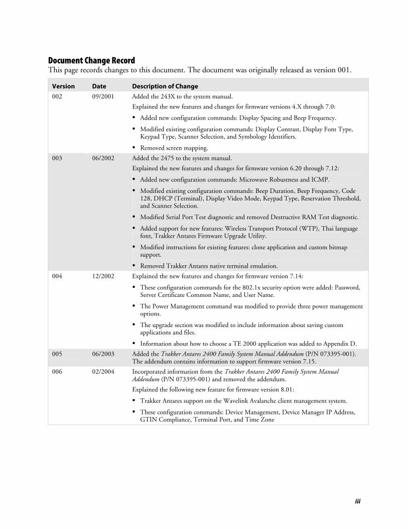
Document Change Record This page records changes to this document. The document was originally released as version 001.
Version Date Description of Change
002 09/2001 Added the 243X to the system manual.
Explained the new features and changes for firmware versions 4.X through 7.0:
• Added new configuration commands: Display Spacing and Beep Frequency.
• Modified existing configuration commands: Display Contrast, Display Font Type, Keypad Type, Scanner Selection, and Symbology Identifiers.
• Removed screen mapping. 003 06/2002 Added the 2475 to the system manual.
Explained the new features and changes for firmware version 6.20 through 7.12:
• Added new configuration commands: Microwave Robustness and ICMP.
• Modified existing configuration commands: Beep Duration, Beep Frequency, Code 128, DHCP (Terminal), Display Video Mode, Keypad Type, Reservation Threshold, and Scanner Selection.
• Modified Serial Port Test diagnostic and removed Destructive RAM Test diagnostic.
• Added support for new features: Wireless Transport Protocol (WTP), Thai language font, Trakker Antares Firmware Upgrade Utility.
• Modified instructions for existing features: clone application and custom bitmap support.
• Removed Trakker Antares native terminal emulation. 004 12/2002 Explained the new features and changes for firmware version 7.14:
• These configuration commands for the 802.1x security option were added: Password, Server Certificate Common Name, and User Name.
• The Power Management command was modified to provide three power management options.
• The upgrade section was modified to include information about saving custom applications and files.
• Information about how to choose a TE 2000 application was added to Appendix D. 005 06/2003 Added the Trakker Antares 2400 Family System Manual Addendum (P/N 073395-001).
The addendum contains information to support firmware version 7.15.
006 02/2004 Incorporated information from the Trakker Antares 2400 Family System Manual Addendum (P/N 073395-001) and removed the addendum.
Explained the following new feature for firmware version 8.01:
• Trakker Antares support on the Wavelink Avalanche client management system.
• These configuration commands: Device Management, Device Manager IP Address, GTIN Compliance, Terminal Port, and Time Zone

iv
Contents
v
Contents
Before You Begin................................................................................................................xv Safety Summary.....................................................................................................xv Safety Icons ..........................................................................................................xvi Global Services and Support .................................................................................xvi Who Should Read This Document? ....................................................................xvii Related Documents ............................................................................................xviii
Introducing the Trakker Antares 2400 Family............................................................. 1
What Is the Trakker Antares 2400 Family? .......................................................................... 2
Trakker Antares 241X Terminals ......................................................................................... 2
Trakker Antares 242X Terminals ......................................................................................... 3
Trakker Antares 243X Terminals ......................................................................................... 3
Trakker Antares 2455 Terminal........................................................................................... 4
Trakker Antares 246X Terminals ......................................................................................... 4
Trakker Antares 2475 Terminal........................................................................................... 5
Trakker Antares 248X Terminals ......................................................................................... 5
What’s New in Firmware Version 8.01?............................................................................... 6
About Network Connectivity and Protocols ........................................................................ 6
Configuring and Managing the Terminals ................................................................... 11
How to Configure the Terminals....................................................................................... 12 About the Configurations ..................................................................................... 13
Configuring the Terminal by Scanning Bar Code Labels.................................................... 13
Configuring the Terminal Through the Serial Port ............................................................ 15
Configuring the Terminal Through the Network .............................................................. 17 Sending a Command From the DCS 300............................................................. 18 Sending a Command From the Host .................................................................... 19
Configuring the Terminal in a UDP Plus Network.................................. 19 Configuring the Terminal in a TCP/IP Direct Connect Network............ 20
Configuring the Terminal With the Clone Application ..................................................... 23
Transferring Files and Data in a TCP/IP Direct Connect Network ................................... 24
1
2
Contents
vi
Saving Configuration Changes in Flash Memory ............................................................... 29
Restoring the Terminal’s Default Configuration ................................................................ 30
Upgrading the Terminal .................................................................................................... 31 Upgrading the Firmware....................................................................................... 31 Loading Double-Byte Fonts.................................................................................. 36
Managing Your Terminals with Wavelink Avalanche......................................................... 38 Learning About Wavelink Avalanche .................................................................... 38
Wavelink Avalanche Files ........................................................................ 39 Synchronization Properties and Selection Criteria.................................... 41
Learning About Intermec Settings (ICCU) ........................................................... 42
Developing and Using Applications ................................................................................ 45
About the Trakker Antares Programmable Terminals ........................................................ 46
Creating Applications for the Terminal.............................................................................. 48 Using the PSK or EZBuilder to Develop Applications .......................................... 49
Developing Applications Using the PSK.................................................. 49 Developing Applications Using EZBuilder .............................................. 49
Converting JANUS Applications and IRL Programs............................................. 50 Converting Applications Between JANUS and Trakker Antares .............. 50 Converting IRL Programs Between the 95XX and Trakker Antares ......... 51
Converting the Application to a Binary File.......................................................... 51 Creating a Custom Logo....................................................................................... 52
How to Download Applications ........................................................................................ 53
Using the Serial Port to Transfer Applications and Files..................................................... 55
Using the DCS 300 to Download Applications and Files................................................... 60 Copying Applications and Files to the DCS 300................................................... 61 Downloading Applications and Files to the Terminal ........................................... 62
Running Applications on the Terminal.............................................................................. 65
Running Diagnostics ................................................................................................................. 67
What Diagnostics Are Available?........................................................................................ 68
Running Diagnostics From the Menu System.................................................................... 69
Defining the Diagnostics Screens ....................................................................................... 71 Access Point.......................................................................................................... 72 Application Efficiency........................................................................................... 72 Application Events................................................................................................ 73 Battery/PIC Status ................................................................................................ 73
241X, 242X, and 243X Terminals ........................................................... 73 2455, 2475, and 248X Terminals ............................................................ 75
Beeper Test........................................................................................................... 76
3
4
Contents
vii
Clear Task Profiles................................................................................................ 76 Code Verify .......................................................................................................... 77 Display Test.......................................................................................................... 77 Error Logger ......................................................................................................... 78 Font Test.............................................................................................................. 79 Hardware Configuration....................................................................................... 80 Keypad Table........................................................................................................ 80 Keypad Test.......................................................................................................... 82 Malloc Application Information ........................................................................... 82 Malloc Firmware Information............................................................................... 83 Radio Test ............................................................................................................ 83 Scanner Test ......................................................................................................... 84 Serial Port Test ..................................................................................................... 85 Subsystem Versions............................................................................................... 86 Task Status ........................................................................................................... 86
Error Numbers and Messages............................................................................................. 87
Reader Command Reference................................................................................................ 95
Using Reader Commands .................................................................................................. 96
Reader Commands Listed by Category .............................................................................. 96
Using Accumulate Mode ................................................................................................... 97
Defining the Reader Commands........................................................................................ 99 Abort Program...................................................................................................... 99 Backlight On and Off ......................................................................................... 100 Backspace ........................................................................................................... 100 Boot Terminal .................................................................................................... 100 Change Configuration ........................................................................................ 101 Clear................................................................................................................... 101 Default Configuration ........................................................................................ 101 Delete File .......................................................................................................... 102 Enter .................................................................................................................. 103 Enter Accumulate Mode..................................................................................... 103 Exit Accumulate Mode ....................................................................................... 104 List Files ............................................................................................................. 104 TRAKKER Antares 2400 Menu System ............................................................. 104 Multiple-Read Labels.......................................................................................... 104 Receive File......................................................................................................... 105
Receive File Through the Serial Port...................................................... 105 Receive and Convert 7-Bit ASCII Files to 8-Bit Binary Files.................. 107 Receive File Through Network Communications .................................. 109
Rename File........................................................................................................ 110 Reset Firmware ................................................................................................... 111 Run Program...................................................................................................... 112 Save Configuration in Flash Memory.................................................................. 113 Scanner Trigger On and Off............................................................................... 113 Set Time and Date.............................................................................................. 114 Status Lights Control.......................................................................................... 115
5
Contents
viii
Transmit File ...................................................................................................... 116 Transmit File Through the Serial Port ................................................... 117 Transmit and Convert 8-Bit Binary Files to 7-Bit ASCII Files ............... 118 Transmit File Through Network Communications ............................... 120
Configuration Command Reference .............................................................................. 123
Using Configuration Commands..................................................................................... 124
Configuration Commands Listed by Category ................................................................. 125
Entering Variable Data in a Configuration Command..................................................... 128
Entering ASCII Characters .............................................................................................. 129
Acknowledgement Delay Lower Limit ............................................................................. 131
Acknowledgement Delay Upper Limit............................................................................. 132
AP Density ...................................................................................................................... 133
AP MAC Address ............................................................................................................ 134
Append Time .................................................................................................................. 134
Automatic Shutoff ........................................................................................................... 135
Baud Rate ........................................................................................................................ 136
Beep Duration ................................................................................................................. 138
Beep Frequency ............................................................................................................... 139
Beep Volume ................................................................................................................... 140
Character Set ................................................................................................................... 141
Codabar........................................................................................................................... 143
Code 11........................................................................................................................... 144
Code 2 of 5...................................................................................................................... 145
Code 39........................................................................................................................... 146
Code 93........................................................................................................................... 149
Code 128......................................................................................................................... 150 UCC/EAN Code 128......................................................................................... 151 ISBT Code 128 .................................................................................................. 152
Command Processing ...................................................................................................... 158 Using the Override Options ............................................................................... 161
6
Contents
ix
Configuration Commands Via Serial Port........................................................................ 161
Controller Connect Check Receive Timer ....................................................................... 163
Controller Connect Check Send Timer ........................................................................... 164
Controller IP Address ...................................................................................................... 166
Data Bits.......................................................................................................................... 167
Decode Security............................................................................................................... 168
Default Router................................................................................................................. 169
Device Management ........................................................................................................ 170
Device Manager IP Address ............................................................................................. 171
DHCP (Controller) ......................................................................................................... 173
DHCP (Terminal)........................................................................................................... 174
Display Backlight Timeout .............................................................................................. 175
Display Contrast.............................................................................................................. 176
Display Font Type........................................................................................................... 178
Display Row Spacing ....................................................................................................... 179
Display Spacing ............................................................................................................... 180
Display Video Mode........................................................................................................ 182
Domain ........................................................................................................................... 183
End of Message (EOM) ................................................................................................... 184
Flash Memory Configuration........................................................................................... 186
Flow Control ................................................................................................................... 187
GTIN Compliance .......................................................................................................... 189
Handshake....................................................................................................................... 190
Host IP Address............................................................................................................... 192
ICMP (Internet Control Message Protocol) ..................................................................... 193
Inactivity Timeout........................................................................................................... 193
Interleaved 2 of 5............................................................................................................. 195
Contents
x
Keypad Caps Lock ........................................................................................................... 196
Keypad Clicker ................................................................................................................ 197
Keypad Control ............................................................................................................... 197
Keypad Type ................................................................................................................... 198
Longitudinal Redundancy Check (LRC).......................................................................... 201
Maximum Retries ............................................................................................................ 202
Maximum Sleep Duration ............................................................................................... 203
Medium Reservation........................................................................................................ 204
Microwave Robustness..................................................................................................... 205
Modem Dial Sequence..................................................................................................... 205
Modem Initialization Sequence........................................................................................ 206
MSI ................................................................................................................................. 208
Multi-Drop Address ........................................................................................................ 209
Network Activate............................................................................................................. 210
Network Loopback .......................................................................................................... 211
Network Name................................................................................................................ 211
Network Port................................................................................................................... 213
Parity ............................................................................................................................... 214
Password.......................................................................................................................... 215
PDF417........................................................................................................................... 216
Plessey ............................................................................................................................. 217
Poll (Polling) ................................................................................................................... 218
Postamble ........................................................................................................................ 219
Power Management ......................................................................................................... 220
Preamble.......................................................................................................................... 221
Radio MAC Address ........................................................................................................ 222
RAM Drive Size............................................................................................................... 223
Contents
xi
Receive All Multicast ....................................................................................................... 224
Reservation Threshold ..................................................................................................... 225
Resume Execution ........................................................................................................... 226
RS-232 or RS-422/485 COM2 Interface......................................................................... 226
Roaming Flag .................................................................................................................. 227
Scan Ahead ...................................................................................................................... 228
Scanner Mode.................................................................................................................. 228
Scanner Port (COM4) ..................................................................................................... 229
Scanner Redundancy ....................................................................................................... 230
Scanner Selection............................................................................................................. 231
Scanner Timeout ............................................................................................................. 233
Scanner Trigger ............................................................................................................... 235
Security Identification...................................................................................................... 236
Serial Port Protocol.......................................................................................................... 237
Server Certificate Common Name (Server Cert CN) ....................................................... 239
Start of Message (SOM)................................................................................................... 240
Station Name................................................................................................................... 242
Stop Bits .......................................................................................................................... 242
Subnet Mask.................................................................................................................... 243
Suspend/Resume Control ................................................................................................ 245
Symbology Identifiers ...................................................................................................... 245
TCP Maximum Retries.................................................................................................... 250
TCP/IP Maximum Transmit Timeout ............................................................................ 251
Terminal IP Address ........................................................................................................ 252
Terminal Port .................................................................................................................. 254
Time and Date ................................................................................................................ 255
Time in Seconds .............................................................................................................. 256
Contents
xii
Time Zone....................................................................................................................... 256
Timeout Delay ................................................................................................................ 257
Transmit Mode................................................................................................................ 259
Transmit Rate.................................................................................................................. 260
Transmit Rate Fallback.................................................................................................... 261
UPC/EAN....................................................................................................................... 261
User Name ...................................................................................................................... 265
Wakeup On Broadcast..................................................................................................... 266
WEP Encryption ............................................................................................................. 266
WEP Key......................................................................................................................... 267
WEP Transmit Key ......................................................................................................... 269
Default Configurations and Command Syntax ....................................................... 271
Default Configuration ..................................................................................................... 272
Configuration Commands by Syntax ............................................................................... 276
Full ASCII Charts......................................................................................................................... 281
Full ASCII Table ............................................................................................................. 282
Full ASCII Bar Code Chart ............................................................................................. 284 Control Characters ............................................................................................. 284 Symbols and Punctuation Marks ........................................................................ 285 Numbers............................................................................................................. 286 Uppercase Letters................................................................................................ 287 Lowercase Letters................................................................................................ 288
International Character Support ..................................................................................... 289
Trakker Antares Terminal Font Set.................................................................................. 290 English and Western European Font Set............................................................. 290 Japanese Katakana Font Set ................................................................................ 298
Using Default and Optional Applications................................................................... 301
About the Applications Shipped on the Terminal ............................................................ 302 Identifying the Default Applications ................................................................... 302
TE 2000 Terminal Emulation ............................................................... 302 dcBrowser Client ................................................................................... 303
A
B
C
D
Contents
xiii
Defining APPTSK.BIN and EM9560.BIN...................................................................... 303 Defining the Emulation Features of EM9560.BIN ............................................. 304
Using Display Control Codes ................................................................ 305 Using Display Modes............................................................................. 306 Using Accumulate Mode ....................................................................... 307 Setting Preambles and Postambles ......................................................... 308 Full ASCII Mode for Code 39 ............................................................... 309 Using Message Length Headers.............................................................. 310 Unsupported 95XX Features.................................................................. 311
Running APPTSK.BIN and EM9560.BIN......................................................... 311
Using DOS on the Terminal ........................................................................................... 313 Starting DOS on the Terminal ........................................................................... 315 Running DOS Applications and Using ROM-DOS Commands ........................ 316
Using ROM-DOS Commands.............................................................. 317 Using the PM.COM Command............................................................ 320
Stopping DOS and Running a .BIN Application................................................ 321
Customizing DOS Drives and Commands ...................................................................... 321 Trakker Antares DOS Software Tools................................................................. 321 Customizing Drive A.......................................................................................... 322
Changing DOS Files on Drive A ........................................................... 323 Customizing Drive B .......................................................................................... 324 Configuring a DOS RAM Drive......................................................................... 325
Limitations of ROM-DOS .............................................................................................. 327 DOS Architecture on the Terminal .................................................................... 328
Index ................................................................................................................................................. 329 I

Contents
xiv

Before You Begin
Trakker Antares 2400 Family System Manual xv
Before You Begin This section provides you with safety information, technical support information, and sources for additional product information.
Safety Summary Your safety is extremely important. Read and follow all warnings and cautions in this document before handling and operating Intermec equipment. You can be seriously injured, and equipment and data can be damaged if you do not follow the safety warnings and cautions.
Do not repair or adjust alone Do not repair or adjust energized equipment alone under any circumstances. Someone capable of providing first aid must always be present for your safety.
First aid Always obtain first aid or medical attention immediately after an injury. Never neglect an injury, no matter how slight it seems.
Resuscitation Begin resuscitation immediately if someone is injured and stops breathing. Any delay could result in death. To work on or near high voltage, you should be familiar with approved industrial first aid methods.
Energized equipment Never work on energized equipment unless authorized by a responsible authority. Energized electrical equipment is dangerous. Electrical shock from energized equipment can cause death. If you must perform authorized emergency work on energized equipment, be sure that you comply strictly with approved safety regulations.
Before You Begin
xvi Trakker Antares 2400 Family System Manual
Safety Icons This section explains how to identify and understand dangers, warnings, cautions, and notes that are in this document. You may also see icons that tell you when to follow ESD procedures and when to take special precautions for handling optical parts.
A warning alerts you of an operating procedure, practice, condition, or statement that must be strictly observed to avoid death or serious injury to the persons working on the equipment.
Avertissement: Un avertissement vous avertit d’une procédure de fonctionnement, d’une méthode, d’un état ou d’un rapport qui doit être strictement respecté pour éviter l’occurrence de mort ou de blessures graves aux personnes manupulant l’équipement.
A caution alerts you to an operating procedure, practice, condition, or statement that must be strictly observed to prevent equipment damage or destruction, or corruption or loss of data.
Attention: Une précaution vous avertit d’une procédure de fonctionnement, d’une méthode, d’un état ou d’un rapport qui doit être strictement respecté pour empêcher l’endommagement ou la destruction de l’équipement, ou l’altération ou la perte de données.
Note: Notes either provide extra information about a topic or contain special instructions for handling a particular condition or set of circumstances.
Global Services and Support
Warranty Information To understand the warranty for your Intermec product, visit the Intermec web site at http://www.intermec.com and click Service & Support. The Intermec Global Sales & Service page appears. From the Service & Support menu, move your pointer over Support, and then click Warranty.
Disclaimer of warranties: The sample code included in this document is presented for reference only. The code does not necessarily represent complete, tested programs. The code is provided “as is with all faults.” All warranties are expressly disclaimed, including the implied warranties of merchantability and fitness for a particular purpose.
Before You Begin
Trakker Antares 2400 Family System Manual xvii
Web Support Visit the Intermec web site at http://www.intermec.com to download our current documents in PDF format. To order printed versions of the Intermec manuals, contact your local Intermec representative or distributor.
Visit the Intermec technical knowledge base (Knowledge Central) at http://intermec.custhelp.com to review technical information or to request technical support for your Intermec product.
Telephone Support These services are available from Intermec Technologies Corporation.
Service
Description
In the U.S.A. and Canada call 1-800-755-5505 and choose this option
Factory Repair and On-site Repair
Request a return authorization number for authorized service center repair, or request an on-site repair technician.
1
Technical Support Get technical support on your Intermec product.
2
Service Contract Status
Inquire about an existing contract, renew a contract, or ask invoicing questions.
3
Schedule Site Surveys or Installations
Schedule a site survey, or request a product or system installation.
4
Ordering Products Talk to sales administration, place an order, or check the status of your order.
5
Outside the U.S.A. and Canada, contact your local Intermec representative. To search for your local representative, from the Intermec web site, click Contact.
Who Should Read This Document? This manual provides you with information about how to configure, operate, and program the Trakker Antares® 2400 Family of terminals. Use this manual in conjunction with your terminal user’s manual, which contains specific information about installing, configuring, operating, troubleshooting, and maintaining your terminal.
You should be familiar with your network and general networking terms, such as IP address.
Before You Begin
xviii Trakker Antares 2400 Family System Manual
Related Documents The Intermec web site at http://www.intermec.com contains our current documents that you can download as PDF files.
To order printed versions of the Intermec manuals, contact your local Intermec representative or distributor.
Trakker Antares 2400 Family System Manual 1
Introducing the Trakker Antares 2400 Family
This chapter introduces the Trakker Antares® 2400 Family of terminals and covers these topics:
• Overview of the Trakker Antares 2400 Family
• What’s new in firmware version 8.01
• About network connectivity and protocols
1
Chapter 1—Introducing the Trakker Antares 2400 Family
2 Trakker Antares 2400 Family System Manual
What Is the Trakker Antares 2400 Family? The Trakker Antares 2400 Family of terminals provides a comprehensive data collection solution for manufacturing, warehousing, distribution, healthcare, and retail environments. This full family of products shares the same programming tools, configuration, and connectivity. The 2400 Family includes the following terminals:
• 2410 and 2415 handheld
• 2420, 2425, and 2425CS handheld
• 2430 and 2435 handheld
• 2455 vehicle-mount
• 2460 and 2461 light industrial stationary
• 2475 vehicle-mount
• 2480, 2481, 2485, and 2486 heavy industrial stationary
For information about the 2425CS, see the documentation that ships with the 2425CS.
The 2400 Family is a Wi-Fi certified family of products. The 2415, 2425, 2435, 2455, 2475, 2485, and 2486 terminals with an IEEE 802.11b radio installed are Wi-Fi certified for interoperability with other 802.11b wireless LAN devices.
The 2415, 2425, 2435, 2455, 2475, 2485, and 2486 terminals are also supported by the Wavelink Avalanche client management system. For more information, see “Managing Your Terminals with Wavelink Avalanche” on page 38.
Trakker Antares 241X Terminals The Trakker Antares 2410 and 2415 terminals are small, lightweight, handheld data collection terminals that are designed for a range of applications, including commercial applications such as in-store retail.
2410 The 2410 is a programmable data collection terminal that runs custom batch applications. The terminal has a flash drive to store applications and files. The 2410 also has an integrated input/output (I/O) port to transmit data to and accept data from a host or PC through RS-232 serial communications.
Chapter 1—Introducing the Trakker Antares 2400 Family
Trakker Antares 2400 Family System Manual 3
2415 The 2415 has all of the capabilities of the 2410; however, it can also communicate in a radio frequency (RF) network. Because it can communicate using RF, the 2415 provides real-time communications to a host either through the access points and the Intermec Gateway or DCS 30X, or directly through the access points. The 2415 can also run client/server applications, TE 2000™ terminal emulation applications, and Data Collection Browser™ (dcBrowser™), which lets you run web-based applications.
Trakker Antares 242X Terminals The 2420, 2425, and 2425CS terminals are handheld data collection terminals. You can use these programmable terminals to run custom applications or terminal emulation applications.
2420 The 2420 is a programmable data collection terminal that has 512K of RAM reserved for custom applications. The terminal has a 750K flash drive to store applications and files. The 2420 also has a serial port to transmit data to and accept data from a host or PC through RS-232 serial communications.
2425 The 2425 has all of the capabilities of the 2420 with the additional ability to communicate in the RF network. Because it can communicate using RF, the 2425 provides real-time communications to a host either through the access points and Intermec Gateway or DCS 30X, or directly through the access points. The 2425 can also run client/server applications, terminal emulation applications, and dcBrowser, which lets you run web-based applications.
2425CS The 2425CS has all of the capabilities of the 2425 with the addition of the Intrinsically Safe qualification. For more information, see the 2425 Intrinsically Safe Terminal Instruction Sheet (P/N 069311).
Trakker Antares 243X Terminals The 2430 and 2435 terminals are handheld data collection terminals. You can use these programmable terminals to run custom applications or terminal emulation applications.
Chapter 1—Introducing the Trakker Antares 2400 Family
4 Trakker Antares 2400 Family System Manual
2430 The 2430 is a programmable data collection terminal that runs custom batch applications. The 2430 has a flash drive to store applications and files and an integrated I/O port to transmit data to and accept data from a host computer or other serial device using RS-232 communications. The versatile display features of the 2430 allow you to resize the screen up to 21 lines by 31 characters based on operator preference and work environment.
2435 The 2435 has all of the same functionality as the 2430 with the additional ability for real-time communications through an RF network. The 2435 can communicate with a host either through the access points and the Intermec Gateway or DCS 30X, or directly through the access points. The 2435 can also run client/server applications, TE 2000 terminal emulation applications and dcBrowser, which lets you run web-based applications.
Trakker Antares 2455 Terminal The 2455 is a vehicle-mount data collection terminal that can communicate in an RF network. You can use this programmable terminal to run client/server applications, terminal emulation applications, and dcBrowser, which lets you run web-based applications.
Trakker Antares 246X Terminals The Trakker Antares 2460 and 2461 stationary terminals are desktop data collection terminals. You can use these programmable terminals to run client/server applications such as work-in-process, time and attendance, or document tracking.
2460 The 2460 is a programmable data collection terminal that uses serial ports to transmit data to and receive data from a host or PC. The 2460 has two serial ports, COM1 and COM2.
2461 The 2461 is a programmable data collection terminal that has both a serial port and an Ethernet connector to transmit data and receive data.
Note: The 246X terminals are mentioned in this manual; however, the primary source of information for these terminals is the user’s manual. For help using the 246X, see the Trakker Antares 246X Stationary Terminal User’s Manual (P/N 068575).
Chapter 1—Introducing the Trakker Antares 2400 Family
Trakker Antares 2400 Family System Manual 5
Trakker Antares 2475 Terminal The 2475 is a vehicle-mount data collection terminal that can communicate in an RF network. You can use this programmable terminal to run client/server applications, terminal emulation applications, and dcBrowser, which lets you run web-based applications.
Trakker Antares 248X Terminals The Trakker Antares 248X terminals (2480, 2481, 2485, and 2486) are compact stationary data collection terminals that are designed for a range of applications including process tracking, labor collection, and time and attendance applications. You can use these programmable terminals to run either client/server applications or terminal emulation.
2480 The 2480 is a programmable data collection terminal. It has a serial port to transmit data to and accept data from a host or PC through RS-232 serial communications. With the optional Ethernet card, the 2480 can also transmit and receive data through Ethernet communications. The 2480 has a 4-line by 40-character screen.
2481 The 2481 has the same functionality as the 2480. The only difference between these two models is the screen size. The 2481 has a 12-line by 40-character screen that is configurable up to 25 lines.
2485 The 2485 is a programmable data collection terminal with the additional ability to communicate in the RF network. The 2485 provides wireless communications to a host either through the access points and Intermec Gateway or DCS 30X, or directly through the access points. The 2485 has a 4-line by 40-character screen.
2486 The 2486 has the same functionality as the 2485. The only difference between these two models is the screen size. The 2486 has a 12-line by 40-character screen that is configurable up to 25 lines.
Chapter 1—Introducing the Trakker Antares 2400 Family
6 Trakker Antares 2400 Family System Manual
What’s New in Firmware Version 8.01?
Note: Firmware version 8.01 is supported on all terminals in the Trakker Antares 2400 Family except for the 246X. The 246X terminal supports firmware version 6.2X and earlier. For help using the 246X terminal, see the Trakker Antares 246X Stationary Terminal User’s Manual (P/N 068575).
With this system manual revision, several significant changes were made to support software for firmware version 8.01:
• Support for the Wavelink Avalanche client management system was added. For more information, see “Managing Your Terminals with Wavelink Avalanche” on page 38.
• These configuration commands were added: Device Management, Device Manager IP Address, GTIN Compliance, Terminal Port, and Time Zone. For more information, see Chapter 6, “Configuration Command Reference.”
• “Entering ASCII Characters” on page 129 was added to describe how to enter characters using the TRAKKER Antares 2400 Menu System.
• These updates from the Trakker Antares 2400 Family System Manual Addendum (P/N 073395) were added:
• Keypad Table diagnostic
• AP Density, Display Spacing, Keypad Type, and Scanner Selection configuration commands
About Network Connectivity and Protocols The 2400 Family of terminals are data collection terminals with network support. The terminals communicate with a host computer or other serial device through the terminal’s serial port. The Ethernet terminal communicates with a host directly through the Ethernet network. The RF terminal also communicates with a host either through the Intermec Gateway or DCS 30X, or directly through the access points. The access point acts as a bridge between the Ethernet or wired network and the RF network.
Chapter 1—Introducing the Trakker Antares 2400 Family
Trakker Antares 2400 Family System Manual 7
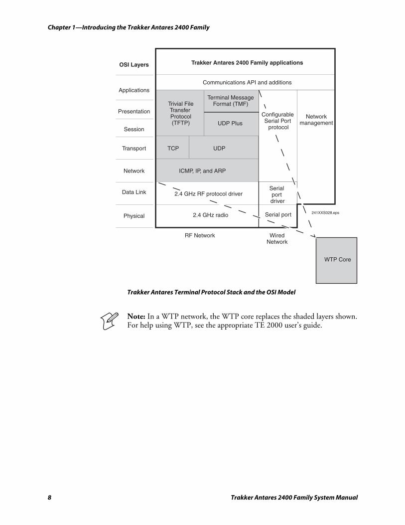
In a UDP Plus or WTP network, the terminal communicates through an access point using the Intermec Gateway or DCS 30X to a host on a wired network. In a TCP/IP network, the terminal communicates through the access point directly to a host on a wired network.
The communications protocol stack for the terminal is developed using the Open Systems Interconnection (OSI) seven-layer model. The next illustration shows how the network and RS-232 serial port map into the OSI model.
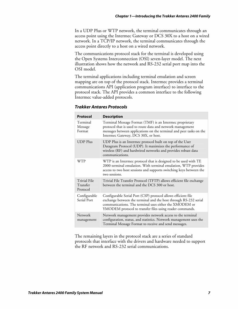
The terminal applications including terminal emulation and screen mapping are on top of the protocol stack. Intermec provides a terminal communications API (application program interface) to interface to the protocol stack. The API provides a common interface to the following Intermec value-added protocols.
Trakker Antares Protocols
Protocol Description
Terminal Message Format
Terminal Message Format (TMF) is an Intermec proprietary protocol that is used to route data and network management messages between applications on the terminal and peer tasks on the Intermec Gateway, DCS 30X, or host.
UDP Plus UDP Plus is an Intermec protocol built on top of the User Datagram Protocol (UDP). It maximizes the performance of wireless (RF) and hardwired networks and provides robust data communications.
WTP WTP is an Intermec protocol that is designed to be used with TE 2000 terminal emulation. With terminal emulation, WTP provides access to two host sessions and supports switching keys between the two sessions.
Trivial File Transfer Protocol
Trivial File Transfer Protocol (TFTP) allows efficient file exchange between the terminal and the DCS 300 or host.
Configurable Serial Port
Configurable Serial Port (CSP) protocol allows efficient file exchange between the terminal and the host through RS-232 serial communications. The terminal uses either the XMODEM or YMODEM protocol to transfer files using reader commands.
Network management
Network management provides network access to the terminal configuration, status, and statistics. Network management uses the Terminal Message Format to receive and send messages.
The remaining layers in the protocol stack are a series of standard protocols that interface with the drivers and hardware needed to support the RF network and RS-232 serial communications.
Chapter 1—Introducing the Trakker Antares 2400 Family
8 Trakker Antares 2400 Family System Manual
Trakker Antares 2400 Family applications
Communications API and additions
WTP Core
OSI Layers
Applications
Presentation
Session
Transport
Network
Data Link
Physical
2.4 GHz RF protocol driverSerial port driver
Serial port 241XXS028.eps2.4 GHz radio
RF Network WiredNetwork
Configurable Serial Port
protocol
Terminal MessageFormat (TMF)
UDP Plus
TCP UDP
ICMP, IP, and ARP
Trivial FileTransfer Protocol(TFTP)
Networkmanagement
Trakker Antares Terminal Protocol Stack and the OSI Model
Note: In a WTP network, the WTP core replaces the shaded layers shown. For help using WTP, see the appropriate TE 2000 user’s guide.
Chapter 1—Introducing the Trakker Antares 2400 Family
Trakker Antares 2400 Family System Manual 9
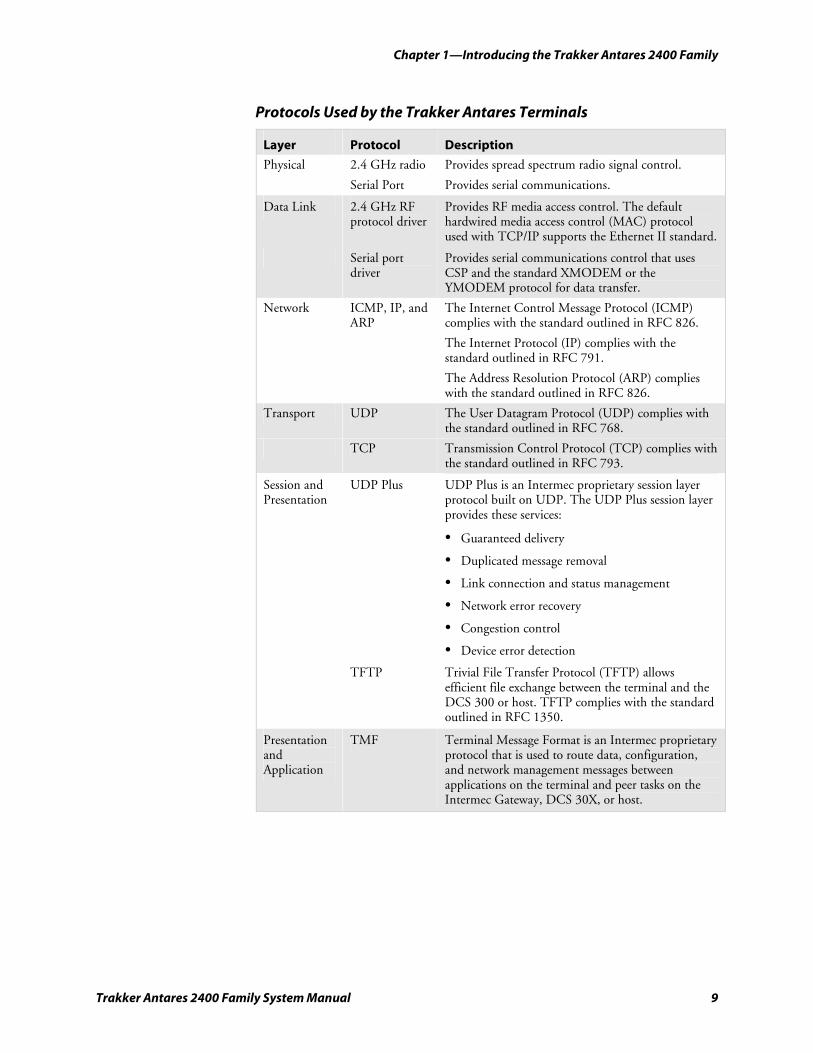
Protocols Used by the Trakker Antares Terminals
Layer Protocol Description
Physical 2.4 GHz radio
Serial Port
Provides spread spectrum radio signal control.
Provides serial communications.
Data Link 2.4 GHz RF protocol driver
Provides RF media access control. The default hardwired media access control (MAC) protocol used with TCP/IP supports the Ethernet II standard.
Serial port driver
Provides serial communications control that uses CSP and the standard XMODEM or the YMODEM protocol for data transfer.
Network ICMP, IP, and ARP
The Internet Control Message Protocol (ICMP) complies with the standard outlined in RFC 826.
The Internet Protocol (IP) complies with the standard outlined in RFC 791.
The Address Resolution Protocol (ARP) complies with the standard outlined in RFC 826.
Transport UDP The User Datagram Protocol (UDP) complies with the standard outlined in RFC 768.
TCP Transmission Control Protocol (TCP) complies with the standard outlined in RFC 793.
Session and Presentation
UDP Plus UDP Plus is an Intermec proprietary session layer protocol built on UDP. The UDP Plus session layer provides these services:
• Guaranteed delivery
• Duplicated message removal
• Link connection and status management
• Network error recovery
• Congestion control
• Device error detection TFTP Trivial File Transfer Protocol (TFTP) allows
efficient file exchange between the terminal and the DCS 300 or host. TFTP complies with the standard outlined in RFC 1350.
Presentation and Application
TMF Terminal Message Format is an Intermec proprietary protocol that is used to route data, configuration, and network management messages between applications on the terminal and peer tasks on the Intermec Gateway, DCS 30X, or host.
Chapter 1—Introducing the Trakker Antares 2400 Family
10 Trakker Antares 2400 Family System Manual
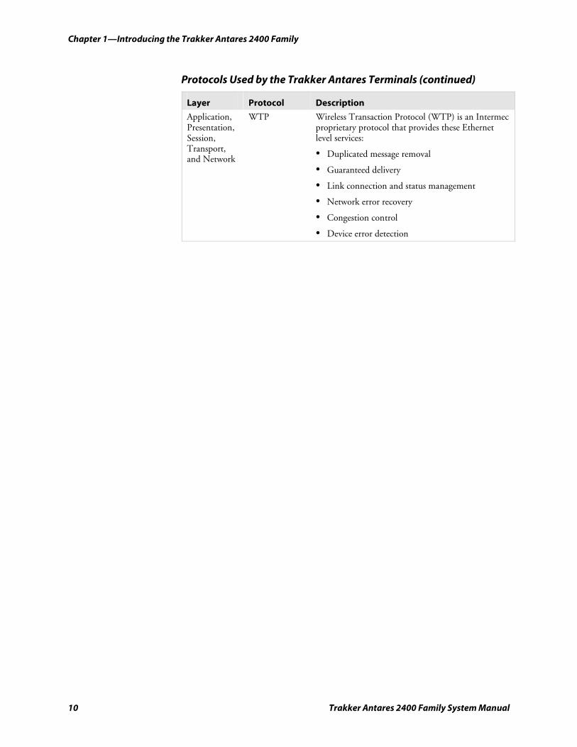
Protocols Used by the Trakker Antares Terminals (continued)
Layer Protocol Description
Application, Presentation, Session, Transport, and Network
WTP Wireless Transaction Protocol (WTP) is an Intermec proprietary protocol that provides these Ethernet level services:
• Duplicated message removal
• Guaranteed delivery
• Link connection and status management
• Network error recovery
• Congestion control
• Device error detection
Trakker Antares 2400 Family System Manual 11
Configuring and Managing the Terminals
This chapter describes the different methods you can use to configure the Trakker Antares® terminals and covers these topics:
• Overview of how to configure the terminals
• Configuring the terminal by scanning bar code labels
• Configuring the terminal through the serial port
• Configuring the terminal through the network
• Configuring the terminal with the clone application
• Transferring files and data in a TCP/IP direct connect network
• Saving configuration changes in flash memory
• Restoring the terminal’s default configuration
• Upgrading the terminal
• Managing your terminals with Wavelink Avalanche
2
Chapter 2—Configuring and Managing the Terminals
12 Trakker Antares 2400 Family System Manual
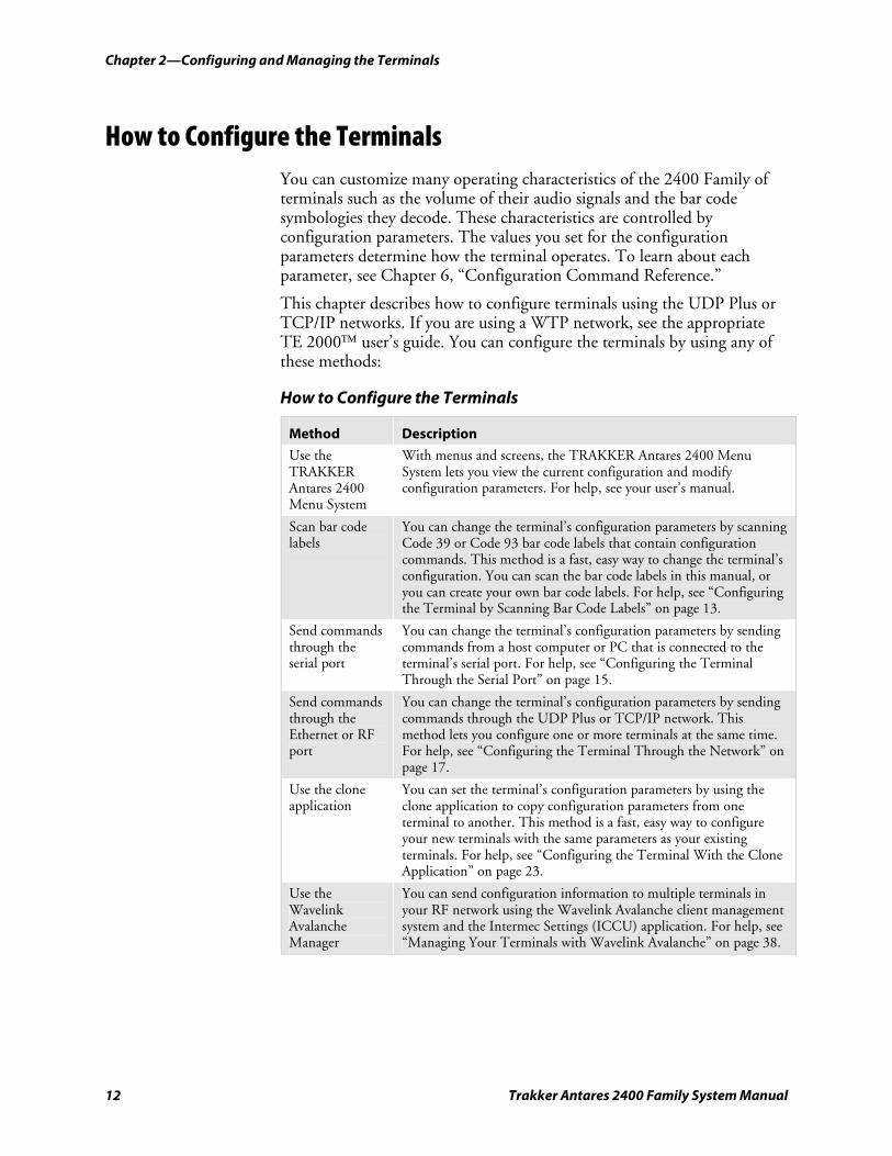
How to Configure the Terminals You can customize many operating characteristics of the 2400 Family of terminals such as the volume of their audio signals and the bar code symbologies they decode. These characteristics are controlled by configuration parameters. The values you set for the configuration parameters determine how the terminal operates. To learn about each parameter, see Chapter 6, “Configuration Command Reference.”
This chapter describes how to configure terminals using the UDP Plus or TCP/IP networks. If you are using a WTP network, see the appropriate TE 2000™ user’s guide. You can configure the terminals by using any of these methods:
How to Configure the Terminals
Method Description
Use the TRAKKER Antares 2400 Menu System
With menus and screens, the TRAKKER Antares 2400 Menu System lets you view the current configuration and modify configuration parameters. For help, see your user’s manual.
Scan bar code labels
You can change the terminal’s configuration parameters by scanning Code 39 or Code 93 bar code labels that contain configuration commands. This method is a fast, easy way to change the terminal’s configuration. You can scan the bar code labels in this manual, or you can create your own bar code labels. For help, see “Configuring the Terminal by Scanning Bar Code Labels” on page 13.
Send commands through the serial port
You can change the terminal’s configuration parameters by sending commands from a host computer or PC that is connected to the terminal’s serial port. For help, see “Configuring the Terminal Through the Serial Port” on page 15.
Send commands through the Ethernet or RF port
You can change the terminal’s configuration parameters by sending commands through the UDP Plus or TCP/IP network. This method lets you configure one or more terminals at the same time. For help, see “Configuring the Terminal Through the Network” on page 17.
Use the clone application
You can set the terminal’s configuration parameters by using the clone application to copy configuration parameters from one terminal to another. This method is a fast, easy way to configure your new terminals with the same parameters as your existing terminals. For help, see “Configuring the Terminal With the Clone Application” on page 23.
Use the Wavelink Avalanche Manager
You can send configuration information to multiple terminals in your RF network using the Wavelink Avalanche client management system and the Intermec Settings (ICCU) application. For help, see “Managing Your Terminals with Wavelink Avalanche” on page 38.
Chapter 2—Configuring and Managing the Terminals
Trakker Antares 2400 Family System Manual 13
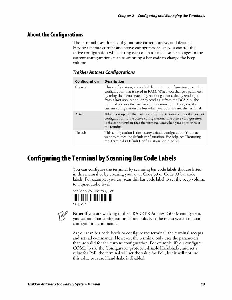
About the Configurations The terminal uses three configurations: current, active, and default. Having separate current and active configurations lets you control the active configuration while letting each operator make some changes to the current configuration, such as scanning a bar code to change the beep volume.
Trakker Antares Configurations
Configuration Description
Current This configuration, also called the runtime configuration, uses the configuration that is saved in RAM. When you change a parameter by using the menu system, by scanning a bar code, by sending it from a host application, or by sending it from the DCS 300, the terminal updates the current configuration. The changes to the current configuration are lost when you boot or reset the terminal.
Active When you update the flash memory, the terminal copies the current configuration to the active configuration. The active configuration is the configuration that the terminal uses when you boot or reset the terminal.
Default This configuration is the factory default configuration. You may want to restore the default configuration. For help, see “Restoring the Terminal’s Default Configuration” on page 30.
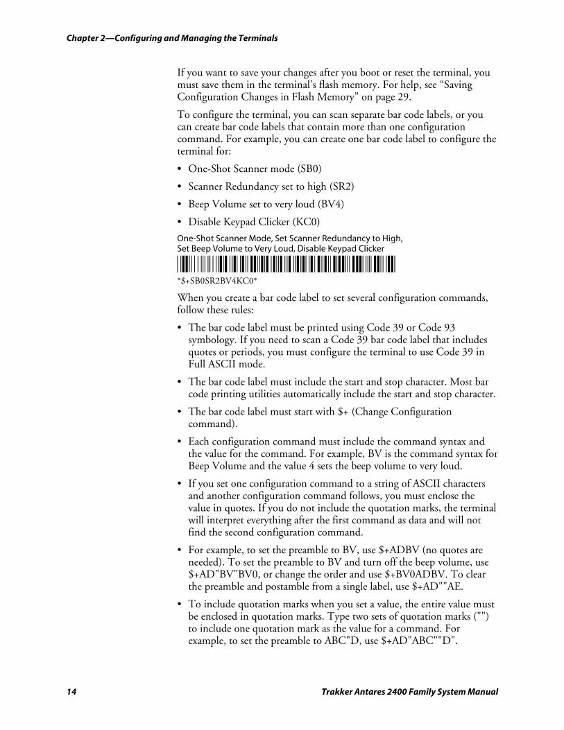
Configuring the Terminal by Scanning Bar Code Labels You can configure the terminal by scanning bar code labels that are listed in this manual or by creating your own Code 39 or Code 93 bar code labels. For example, you can scan this bar code label to set the beep volume to a quiet audio level:
Set Beep Volume to Quiet
*$+BV1* *$+BV1*
Note: If you are working in the TRAKKER Antares 2400 Menu System, you cannot scan configuration commands. Exit the menu system to scan configuration commands.
As you scan bar code labels to configure the terminal, the terminal accepts and sets all commands. However, the terminal only uses the parameters that are valid for the current configuration. For example, if you configure COM1 to use the Configurable protocol, disable Handshake, and set a value for Poll, the terminal will set the value for Poll, but it will not use this value because Handshake is disabled.
Chapter 2—Configuring and Managing the Terminals
14 Trakker Antares 2400 Family System Manual
If you want to save your changes after you boot or reset the terminal, you must save them in the terminal’s flash memory. For help, see “Saving Configuration Changes in Flash Memory” on page 29.
To configure the terminal, you can scan separate bar code labels, or you can create bar code labels that contain more than one configuration command. For example, you can create one bar code label to configure the terminal for:
• One-Shot Scanner mode (SB0)
• Scanner Redundancy set to high (SR2)
• Beep Volume set to very loud (BV4)
• Disable Keypad Clicker (KC0)
One-Shot Scanner Mode, Set Scanner Redundancy to High, Set Beep Volume to Very Loud, Disable Keypad Clicker
*$+SB0SR2BV4KC0* *$+SB0SR2BV4KC0*
When you create a bar code label to set several configuration commands, follow these rules:
• The bar code label must be printed using Code 39 or Code 93 symbology. If you need to scan a Code 39 bar code label that includes quotes or periods, you must configure the terminal to use Code 39 in Full ASCII mode.
• The bar code label must include the start and stop character. Most bar code printing utilities automatically include the start and stop character.
• The bar code label must start with $+ (Change Configuration command).
• Each configuration command must include the command syntax and the value for the command. For example, BV is the command syntax for Beep Volume and the value 4 sets the beep volume to very loud.
• If you set one configuration command to a string of ASCII characters and another configuration command follows, you must enclose the value in quotes. If you do not include the quotation marks, the terminal will interpret everything after the first command as data and will not find the second configuration command.
• For example, to set the preamble to BV, use $+ADBV (no quotes are needed). To set the preamble to BV and turn off the beep volume, use $+AD"BV"BV0, or change the order and use $+BV0ADBV. To clear the preamble and postamble from a single label, use $+AD""AE.
• To include quotation marks when you set a value, the entire value must be enclosed in quotation marks. Type two sets of quotation marks ("") to include one quotation mark as the value for a command. For example, to set the preamble to ABC"D, use $+AD"ABC""D".
Chapter 2—Configuring and Managing the Terminals
Trakker Antares 2400 Family System Manual 15
Configuring the Terminal Through the Serial Port You can write a host application that configures the terminal by sending reader and configuration commands through the serial port. For a list of reader commands, see Chapter 5, “Reader Command Reference.” For a list of configuration commands, see Chapter 6, “Configuration Command Reference.” You must connect the terminal to the host by either using a special cable or a communications dock and a special cable. Once the terminal and the host are communicating, you can configure the terminal.
If you are using the Configurable protocol, you must enable Frame mode and the Configuration Commands Via Serial Port command. You cannot configure the terminal through the serial port if you are using Configurable protocol with no EOM or Binary protocol on that port.
You can continue running an application on the terminal while configuring the terminal from the host. However, if you send a configuration command that changes the serial port parameters, you may not be able to continue sending commands unless you also reconfigure your host. You can also improve TMF performance by disabling the Network Activate command before sending commands through the serial port. For help, see “Network Activate” on page 210.
To set up the application
• Write a host application that can send transactions to and receive transactions from the terminal in this format:
SOM TMF field commands EOM where:
SOM is the start of message field.
TMF field is only used if the Configuration Commands Via Serial Port are enabled with TMF. It is a 2-byte field containing one of these values:
CG Configuration Get request sent from the host application.
Cg Configuration Get response sent from the terminal to the host.
CS Configuration Set request sent from the host application.
Cs Configuration Set response sent from the terminal to the host.
To send data to an application instead of sending configuration commands, use the letter A followed by a space in the TMF field. If the TMF field does not contain CG, Cg, CS, Cs, or A, the terminal ignores the transaction.
Chapter 2—Configuring and Managing the Terminals
16 Trakker Antares 2400 Family System Manual
commands are the reader and configuration commands that you want to set on the terminal or get the current value of from the terminal. To save configuration changes in flash memory, send the reader command .+1 as the last command.
EOM is the end of message field.
If the Configuration Commands Via Serial Port command is enabled without TMF or if you are using a protocol other than Configurable, leave this field blank.
Note: For security purposes, you cannot get the values for Security ID and WEP Key. To get the value for Symbology Identifiers, you need to use the command syntax and the value for Parameter 1. For example, to get the value for the Code 39 symbology identifier, use CY01. For help, see “Symbology Identifiers” on page 245.
Example with TMF In the host application, you want to set the values for the beep volume and keypad caps lock on the terminal. Send this transaction from the host application:
CS$+BV4KA1.+1
Note: SOM and EOM are not shown in this example.
where:
CS is a TMF Configuration Set request.
$+ is the Change Configuration reader command.
BV4 sets the Beep Volume command to a value of 4, which is a very loud beep volume.
KA1 enables the Keypad Caps Lock configuration command.
.+1 saves the configuration changes to the terminal’s flash memory.
The terminal returns this transaction to the host application:
Cs$+BV4KA1.+1
where:
Cs is a TMF Configuration Set response.
$+ is the Change Configuration reader command.
Chapter 2—Configuring and Managing the Terminals
Trakker Antares 2400 Family System Manual 17
BV4 means the Beep Volume command has been changed to
a value of 4, which is a very loud beep volume.
KA1 means the Keypad Caps Lock configuration command was enabled.
.+1 means the configuration changes have been saved in flash memory.
Configuring the Terminal Through the Network You can remotely configure the RF or Ethernet terminal by using one of these methods:
• Send a command from the DCS 300 (UDP Plus network only).
• Send a command from an application on the host computer (UDP Plus and TCP/IP networks).
Before you can send a command to the terminal, it must be communicating with the RF network. You must have already installed and configured the access points. If you are using a UDP Plus network, you must have installed and configured the DCS 300.
You can modify most RF network parameters through the network, except for these parameters:
• Acknowledgement Delay Lower Limit
• Acknowledgement Delay Upper Limit
• Controller Connect Check Receive Timer
• Controller Connect Check Send Timer
• DHCP (Controller)
• DHCP (Terminal)
• Maximum Retries
• Network Activate
• TCP Maximum Retries
• TCP/IP Maximum Transmit Timeout
You can modify these parameters or configure the terminal locally by using the TRAKKER Antares 2400 Menu System or by scanning a command from a Code 39 or Code 93 bar code label.
Note: You can continue running an application on the terminal while configuring the terminal from the network.
Chapter 2—Configuring and Managing the Terminals
18 Trakker Antares 2400 Family System Manual
Sending a Command From the DCS 300 You can use the DCS 300 to configure one or more terminals in your RF or Ethernet network. The DCS 300 lets you group together terminals that you want to receive the same reader and configuration commands.
This method is very efficient if you need to change the same configuration parameters for several terminals in one area. For example, you may want to set the Beep Volume to very loud and turn on Keypad Caps Lock for all the terminals in one area.
Note: You can configure an RF or Ethernet terminal from the DCS 300, but you cannot get configuration data from the terminal.
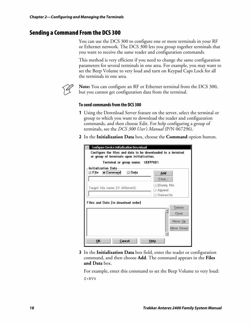
To send commands from the DCS 300
1 Using the Download Server feature on the server, select the terminal or group to which you want to download the reader and configuration commands, and then choose Edit. For help configuring a group of terminals, see the DCS 300 User’s Manual (P/N 067296).
2 In the Initialization Data box, choose the Command option button.
3 In the Initialization Data box field, enter the reader or configuration command, and then choose Add. The command appears in the Files and Data box.
For example, enter this command to set the Beep Volume to very loud:
$+BV4
Chapter 2—Configuring and Managing the Terminals
Trakker Antares 2400 Family System Manual 19
Note: You can set the Postamble or Preamble configuration command to use characters from the extended ASCII character set such as the Field Exit code for 5250 TE. For help, see the appropriate TE manual.
4 Repeat Step 3 to add another reader or configuration command, or choose OK.
5 To save the configuration changes in flash memory, enter .+1 as the last command.
If you do not save the configuration changes in flash memory, the commands only change the current configuration.
6 Choose OK. The Terminal Download Configuration dialog box appears.
7 Choose Download to download the commands and change the configuration of the selected terminals.
Sending a Command From the Host You can write a host application that configures one RF or Ethernet terminal. This host application must be able to communicate with the DCS 300 in a UDP Plus network or directly through the access point in a TCP/IP direct connect network.
Configuring the Terminal in a UDP Plus Network You can use the host computer to configure a terminal in your RF or Ethernet network. To send and receive configuration data or files, you need to write a host application that can communicate with the DCS 300. For help, see the DCS 300 User’s Manual. You use the Terminal Message Format (TMF) protocol to send and receive transactions between the host application and the terminal.
To set up the DCS 300
• Configure a peer-to-peer destination name for the host application. Create a transaction ID, $NGCFGRSP, that will be routed to this destination name. The DCS 300 uses the transaction ID to route responses from the terminal back to the host application. $NGCFGRSP is a special transaction ID that the server uses to forward configuration response data from a terminal.
All configuration responses will be routed with the $NGCFGRSP transaction ID. The DCS 300 cannot keep track of multiple applications sending reader or configuration commands. If you have two host applications sending reader or configuration commands, they must both be configured to receive the $NGCFGRSP transactions, and therefore both will receive all responses from all terminals.
Chapter 2—Configuring and Managing the Terminals
20 Trakker Antares 2400 Family System Manual
To set up the host computer
• Verify that the host computer can communicate with the DCS 300.
To set up the application
• Prepare and write a host application that can communicate with the DCS 300 and send transactions to and receive transactions from the terminal in this format:
transaction header TMF field commands
where:
transaction header
is a 96-byte field containing the message number, date and time, source application ID, destinations application ID, transaction ID, and other information. You must set the system message (SYS$MSG) flag to E in the transaction header. For help, see the DCS 300 User’s Manual.
TMF field is a 2-byte field containing one of these values:
CG Configuration Get request sent from the host application.
Cg Configuration Get response sent from the terminal to the host.
CS Configuration Set request sent from the host application.
Cs Configuration Set response sent from the terminal to the host.
commands are the reader and configuration commands that you want to set on the terminal or the current value you want to retrieve from the terminal. To save configuration changes in flash memory, send the reader command .+1 as the last command.
For a list of commands, see Chapter 5, “Reader Command Reference,” or Chapter 6, “Configuration Command Reference.”
To see examples of the host application transactions, see “Example 1” on page 22 and “Example 2” on page 22.
Configuring the Terminal in a TCP/IP Direct Connect Network You can use the host computer to configure an RF or Ethernet terminal in your TCP/IP network.
To send and receive configuration data, you need to write a host application that can communicate with the terminal directly through an
Chapter 2—Configuring and Managing the Terminals
Trakker Antares 2400 Family System Manual 21
access point or through the Ethernet network. You use the Terminal Message Format (TMF) protocol to send and receive transactions between the host application and the terminal.
For more information about sending and receiving data, see “Transferring Files and Data in a TCP/IP Direct Connect Network” on page 24.
Note: You can continue running an application on the terminal while configuring the terminal from the host.
To set up the host computer
• Verify that you can communicate with the terminal.
To set up the application
• Prepare and write a host application that can communicate with the terminal. Configuration commands must be sent to network port 6000 on the terminal. Message transactions to and receive transactions from the terminal on network port 6000 must conform to the following format:
TMF field commands
where:
TMF field is a 2-byte field containing one of these values:
CG Configuration Get request sent from the host application.
Cg Configuration Get response sent from the terminal to the host.
CS Configuration Set request sent from the host application.
Cs Configuration Set response sent from the terminal to the host.
commands are the reader and configuration commands that you want to set on the terminal or the current value you want to retrieve from the terminal. To save configuration changes in flash memory, send the reader command .+1 as the last command.
For a list of commands, see Chapter 5, “Reader Command Reference,” or Chapter 6, “Configuration Command Reference.”
Chapter 2—Configuring and Managing the Terminals
22 Trakker Antares 2400 Family System Manual
Example 1 In the host application, you want to get the current values of two configuration commands from the terminal. Send this transaction from the host application:
CG$+NABV
Note: The transaction header is not shown in this example. You do not need a transaction header for a host application in a TCP/IP network.
where:
CG is a TMF Configuration Get request.
$+ is the Change Configuration reader command.
NA is the Network Activate configuration command.
BV is the Beep Volume configuration command.
The terminal returns this transaction to the host application.
Cg$+NA1BV4
where:
Cg is a TMF Configuration Get response.
$+ is the Change Configuration reader command.
NA1 means the Network Activate configuration command is currently set to a value of 1, which means that the RF or Ethernet network is enabled.
BV4 means the Beep Volume configuration command is currently set to a value of 4, which is a very loud beep volume.
Example 2 In the host application, you want to set the value for two configuration commands on the terminal. Send this transaction from the host application:
CS$+BV4KA1
Note: The transaction header is not shown in this example. You do not need a transaction header for a host application in a TCP/IP network.
where:
CS is a TMF Configuration Set request.
$+ is the Change Configuration reader command.
Chapter 2—Configuring and Managing the Terminals
Trakker Antares 2400 Family System Manual 23
BV4 sets the Beep Volume configuration command to a value of 4, which is a very loud beep volume.
KA1 sets the Keypad Caps Lock configuration command to a value of 1, which enables the Keypad Caps Lock.
The terminal returns this transaction to the host application.
Cs$+BV4KA1
where:
Cs is a TMF Configuration Set response.
$+ is the Change Configuration reader command.
BV4 means the Beep Volume configuration command has been changed to a value of 4, which is a very loud beep volume.
KA1 means the Keypad Caps Lock configuration command has been changed to a value of 1, which enables the Keypad Caps Lock.
Configuring the Terminal With the Clone Application The clone application uses XMODEM-1K protocol to copy configuration parameters and applications from one terminal (server terminal) to another (client terminal). The server and client terminals must have the same:
• hardware configuration.
• version of firmware.
• version of the clone application.
Note: The clone application does not clone terminals with double-byte fonts or the 802.1x security option.
The clone application copies all configuration parameters from the server terminal to the client terminal, except for:
• terminal IP address.
• security ID.
You need to configure these parameters separately. The clone application also removes all existing files on the client terminal’s C drive and replaces them with the files on the server terminal’s C drive.
For more information about upgrading firmware, see “Upgrading the Firmware” on page 31. For more information about downloading applications, see “How to Download Applications” on page 53.
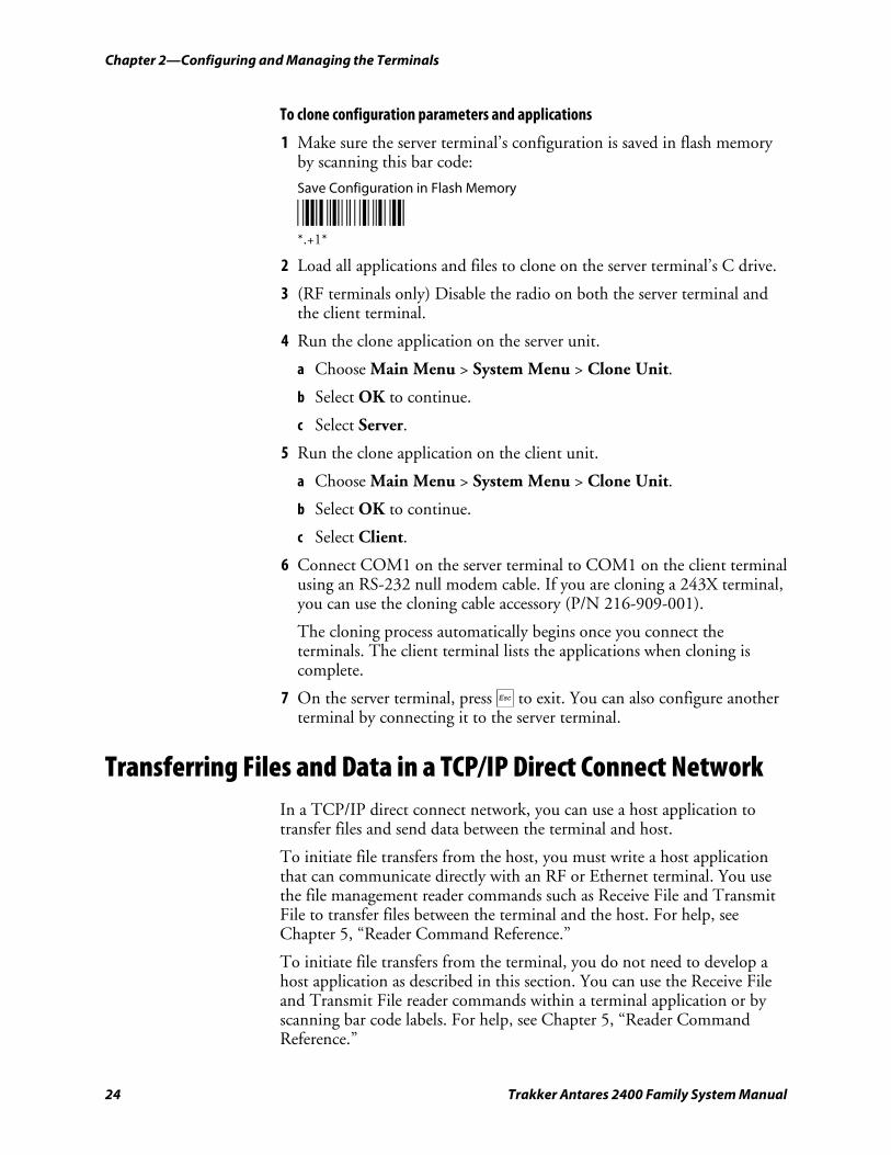
Chapter 2—Configuring and Managing the Terminals
24 Trakker Antares 2400 Family System Manual
To clone configuration parameters and applications
1 Make sure the server terminal’s configuration is saved in flash memory by scanning this bar code:
Save Configuration in Flash Memory
*.+1* *.+1*
2 Load all applications and files to clone on the server terminal’s C drive.
3 (RF terminals only) Disable the radio on both the server terminal and the client terminal.
4 Run the clone application on the server unit.
a Choose Main Menu > System Menu > Clone Unit.
b Select OK to continue.
c Select Server.
5 Run the clone application on the client unit.
a Choose Main Menu > System Menu > Clone Unit.
b Select OK to continue.
c Select Client.
6 Connect COM1 on the server terminal to COM1 on the client terminal using an RS-232 null modem cable. If you are cloning a 243X terminal, you can use the cloning cable accessory (P/N 216-909-001).
The cloning process automatically begins once you connect the terminals. The client terminal lists the applications when cloning is complete.
7 On the server terminal, press d to exit. You can also configure another terminal by connecting it to the server terminal.
Transferring Files and Data in a TCP/IP Direct Connect Network In a TCP/IP direct connect network, you can use a host application to transfer files and send data between the terminal and host.
To initiate file transfers from the host, you must write a host application that can communicate directly with an RF or Ethernet terminal. You use the file management reader commands such as Receive File and Transmit File to transfer files between the terminal and the host. For help, see Chapter 5, “Reader Command Reference.”
To initiate file transfers from the terminal, you do not need to develop a host application as described in this section. You can use the Receive File and Transmit File reader commands within a terminal application or by scanning bar code labels. For help, see Chapter 5, “Reader Command Reference.”
Chapter 2—Configuring and Managing the Terminals
Trakker Antares 2400 Family System Manual 25
To use the built-in TFTP client on the RF or Ethernet terminal, the
• TFTP (Trivial File Transfer Protocol) server must be running on the host.
• TFTP server must be running on at least a Pentium processor or equivalent.
• RF or Ethernet terminal must be communicating with the host that is running the TFTP server.
• TFTP server or some other application on the host must be able to send the reader command on the network.
Note: You can continue running an application, except TE, on the RF or Ethernet terminal while transferring files from the host.
To transfer files or send configuration data from the host
1 Make sure the TFTP server is running on the host and the RF or Ethernet terminal is communicating with the host.
2 Start the host application that can send reader commands to the terminal.
3 Send the two-character TMF code, CS (Configuration Set request) followed by the reader or configuration command. For help with TMF, see “Configuring the Terminal in a TCP/IP Direct Connect Network” on page 20.
For example, to send the application INVENTRY.BIN from drive C on the host to drive C on the terminal, enter this command:
CS.%R,c:inventry.bin,c:inventry.bin
For command information, see Chapter 5, “Reader Command Reference,” or Chapter 6, “Configuration Command Reference.”
CLIENT.CPP is the source for a sample application you can run on the host. You can use CLIENT.CPP to send reader commands to the RF or Ethernet terminal and receive the resulting messages.
The source code for the sample utilities CLIENT.CPP and the include file UTILS.H is shown on the next pages. You can build the application using Microsoft Visual C++ version 4.0 or later and the Windows sockets library that is included with Microsoft Visual C++. You can also develop your own application to meet the needs of your host environment.
You run the resulting application (CLIENT.EXE) from the DOS command line. The application expects NCM to be defined as the terminal IP address in the hosts file. Once running, the application prompts you to enter a reader command, which it then sends to the RF or Ethernet terminal. The application also displays any return messages. Reader commands are handled by the Trakker Antares operating system, so you can continue running an application while you use the CLIENT.EXE application to send commands.
Chapter 2—Configuring and Managing the Terminals
26 Trakker Antares 2400 Family System Manual
To use the sample utility CLIENT.CPP
1 Make sure the TFTP server is running on the host and the RF or Ethernet terminal is communicating with the host.
2 In the hosts file on the host, add the terminal IP addresses and the target name, NCM. For example, to send files or data to the terminal with an IP address of 192.9.200.130, add this line to the hosts file:
192.9.200.130 ncm
3 Start the CLIENT.EXE application on the host.
4 When the “Enter Command” prompt appears on the host, enter the two-character TMF code, CS (Configuration Set request) followed by the reader or configuration command.
For example, to send the application INVENTRY.BIN from drive C on the host to drive C on the terminal, enter this command:
CS.%R,c:inventry.bin,c:inventry.bin
CLIENT.CPP Sample Application for a TCP/IP Direct Connect Network #include <windows.h> #include <stdio.h> #include "Utils.h"
// our application uses a fixed port number const unsigned short SERVER_PORT = 6000; const unsigned short CLIENT_PORT = 6001; // we will default to the local host machine // unless argv[1] has a hostname const char SERVER_HOSTNAME[] = "ncm";
int main(int argc, char *argv[]) { // turn on the socket library for this process WSADATA wsad; int error = WSAStartup(MAKEWORD(1,1), &wsad); if (error != 0) ErrorMessage("WSAStartup", WSAGetLastError());
// create an unitialized connection-oriented socket SOCKET connection; connection = socket(PF_INET, SOCK_DGRAM, 0); if (connection == INVALID_SOCKET) ErrorMessage("socket", WSAGetLastError());
// lookup the IP address of the requested host HOSTENT *phostent = gethostbyname(argc == 2 ? argv[1] : SERVER_HOSTNAME); if (phostent == 0) ErrorMessage("gethostbyname", WSAGetLastError());
// define a SOCKADDR to contain the IP address of the // server and the port number of our application SOCKADDR_IN serverAddress; memset(&serverAddress, 0, sizeof(serverAddress)); serverAddress.sin_family = PF_INET;
Chapter 2—Configuring and Managing the Terminals
Trakker Antares 2400 Family System Manual 27
serverAddress.sin_port = htons(SERVER_PORT); memcpy(&serverAddress.sin_addr, phostent->h_addr_list[0], phostent->h_length); // Bind a well known port of 6000 to the socket SOCKADDR_IN clientAddress; memset(&clientAddress, 0, sizeof(clientAddress)); clientAddress.sin_family = PF_INET; clientAddress.sin_port = htons(CLIENT_PORT); clientAddress.sin_addr.s_addr = htonl(INADDR_ANY); if(!(bind(connection, (LPSOCKADDR)&clientAddress, sizeof(clientAddress))
==0)) { ErrorMessage("bind", WSAGetLastError()); } // attempt to connect to the server error = connect(connection, (const SOCKADDR *)&serverAddress, sizeof(serverAddress)); if (error != 0) ErrorMessage("connect", WSAGetLastError()); // check the local name for the socket SOCKADDR_IN localName; memset(&localName, 0, sizeof(localName)); int localNameLength = sizeof(localName); error = getsockname(connection, (LPSOCKADDR)&localName, &localNameLength); // run the user-interface char sz[1024]; char rz[1024]; BOOL bConnectionAlive = TRUE; printf("> "); int Scount, Rcount; int cbRecv, cbSend; Scount = Rcount = 0; int cbLen, rcLen; unsigned char *psend = (unsigned char *)sz;
// continue while not EOF on the console and the connection is alive while (bConnectionAlive) { // send the string entered by the user printf("Enter Command:\n"); printf("> "); gets(sz); if(sz[0] != 'q') { cbLen = strlen(sz); cbSend = send(connection, (const char *)psend, cbLen, 0); if (cbSend < 0) { Scount++; printf("send failed %d\n", Scount); bConnectionAlive = FALSE; ErrorMessage("send", WSAGetLastError()); }
Chapter 2—Configuring and Managing the Terminals
28 Trakker Antares 2400 Family System Manual
Sleep(2000); // receive the converted string from the server memset(&rz, 0, sizeof(rz)); rcLen = sizeof(rz); cbRecv = recv(connection, rz, rcLen, 0); if (cbRecv < 0) { Rcount++; printf("receive failed %d\n", Rcount); ErrorMessage("receive", WSAGetLastError()); bConnectionAlive = FALSE; } // printf the converted string printf("response:%s\n",rz); printf("\n> "); Sleep(1000); } else bConnectionAlive = FALSE; }
// release the resources held by the socket error = closesocket(connection); if (error != 0) ErrorMessage("closesocket", WSAGetLastError());
// release the resources held by the socket library error = WSACleanup(); if (error != 0) ErrorMessage("WSACleanup", WSAGetLastError()); return 0; }
UTILS.H Utility (Used by CLIENT.CPP) #include <windows.h> inline void ErrorMessage(LPCTSTR szFn, DWORD dwError = GetLastError()) { TCHAR szTitle[1024]; TCHAR szPrompt[1024]; BOOL bRet = FormatMessage(FORMAT_MESSAGE_FROM_SYSTEM, 0, dwError, 0, szPrompt, sizeof(szPrompt), 0); if (!bRet) lstrcpy(szPrompt, __TEXT("Unknown Error")); wsprintf(szTitle, __TEXT("%s failed with error code (0x%x)!"), szFn, dwError); int id = MessageBox(HWND_DESKTOP, szPrompt, szTitle, MB_ABORTRETRYIGNORE|MB_SETFOREGROUND); if (id != IDIGNORE) ExitProcess(0); }
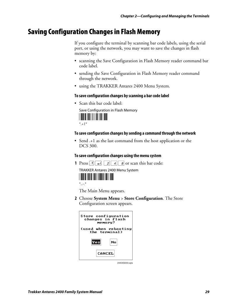
Chapter 2—Configuring and Managing the Terminals
Trakker Antares 2400 Family System Manual 29
Saving Configuration Changes in Flash Memory If you configure the terminal by scanning bar code labels, using the serial port, or using the network, you may want to save the changes in flash memory by:
• scanning the Save Configuration in Flash Memory reader command bar code label.
• sending the Save Configuration in Flash Memory reader command through the network.
• using the TRAKKER Antares 2400 Menu System.
To save configuration changes by scanning a bar code label
• Scan this bar code label:
Save Configuration in Flash Memory
*.+1* *.+1*
To save configuration changes by sending a command through the network
• Send .+1 as the last command from the host application or the DCS 300.
To save configuration changes using the menu system
1 Press ) ; 2 4 8 or scan this bar code:
TRAKKER Antares 2400 Menu System
*..-.* *..-.*
The Main Menu appears.
2 Choose System Menu > Store Configuration. The Store Configuration screen appears.
Store configurationchanges in flash
memory?
(used when rebootingthe terminal)
24XXS033.eps
Yes No
CANCEL
Chapter 2—Configuring and Managing the Terminals
30 Trakker Antares 2400 Family System Manual
3 Choose Yes to save the configuration in flash memory.
To exit without saving the configuration, choose Cancel. The System Menu appears.
4 Press d to exit the System Menu. The Main Menu appears.
5 Choose another menu from the Main Menu or press d to exit the TRAKKER Antares 2400 Menu System.
Restoring the Terminal’s Default Configuration The default configuration for the terminal is listed starting on page 272. You can restore the terminal’s default configuration by:
• scanning the Default Configuration bar code label.
• sending a command through the network.
• using the TRAKKER Antares 2400 Menu System.
If you restore the default configuration, you need to set the primary network communications parameters on the RF terminal to reestablish communications with other devices in the RF network. You may also need to reset the serial port or Ethernet parameters to communicate with other devices in your wired network.
To restore the default configuration by scanning a bar code label
• Scan this bar code label:
Default Configuration
*.+* *.+*
To restore the default configuration by sending a command through the network
• Send .+0 from the host application or the DCS 300.
To restore the default configuration using the menu system
1 Press ) ; 2 4 8 or scan this bar code:
TRAKKER Antares 2400 Menu System
*..-.* *..-.*
The Main Menu appears.
2 Choose System Menu > Load Default Values. The Load Default Values screen appears.
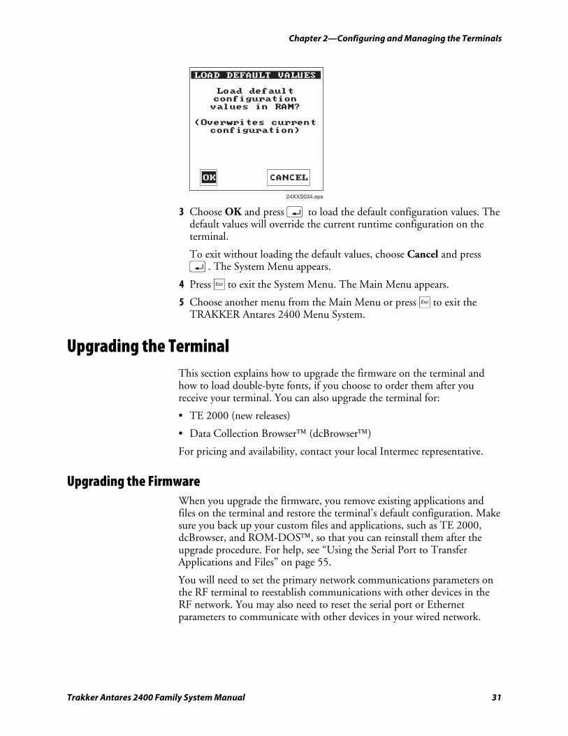
Chapter 2—Configuring and Managing the Terminals
Trakker Antares 2400 Family System Manual 31
LOAD DEFAULT VALUES
Load defaultconfigurationvalues in RAM?
(Overwrites currentconfiguration)
24XXS034.eps
OK CANCEL
3 Choose OK and press ; to load the default configuration values. The default values will override the current runtime configuration on the terminal.
To exit without loading the default values, choose Cancel and press ;. The System Menu appears.
4 Press d to exit the System Menu. The Main Menu appears.
5 Choose another menu from the Main Menu or press d to exit the TRAKKER Antares 2400 Menu System.
Upgrading the Terminal This section explains how to upgrade the firmware on the terminal and how to load double-byte fonts, if you choose to order them after you receive your terminal. You can also upgrade the terminal for:
• TE 2000 (new releases)
• Data Collection Browser™ (dcBrowser™)
For pricing and availability, contact your local Intermec representative.
Upgrading the Firmware When you upgrade the firmware, you remove existing applications and files on the terminal and restore the terminal’s default configuration. Make sure you back up your custom files and applications, such as TE 2000, dcBrowser, and ROM-DOS™, so that you can reinstall them after the upgrade procedure. For help, see “Using the Serial Port to Transfer Applications and Files” on page 55.
You will need to set the primary network communications parameters on the RF terminal to reestablish communications with other devices in the RF network. You may also need to reset the serial port or Ethernet parameters to communicate with other devices in your wired network.
Chapter 2—Configuring and Managing the Terminals
32 Trakker Antares 2400 Family System Manual
Note: Trakker Antares Native terminal emulation is only supported on terminals with firmware version 6.23 and earlier. If you want to upgrade your firmware to version 7.0 or later and continue to use a terminal emulation application, you can order TE 2000. For help, see your local Intermec sales representative.
You can download the latest version of firmware from the Intermec web site at www.intermec.com. When you download the firmware files, you will be prompted to also download the Trakker Antares Firmware Upgrade Utility (TAUPGRADE.EXE) and the FileCopy application (FILECOPYx.x.EXE, where x.x is the version number). Download TAUPGRADE.EXE if you are using a PC with Microsoft Windows 2000/NT/XP. Download FILECOPYx.x.EXE if you have or need to load TE 2000 on your terminal.
You can upgrade your terminal firmware using the:
• Trakker Antares DOS Firmware Upgrade Utility (UPGRADE.BAT). This utility is included with the firmware upgrade. You can use this utility to upgrade the firmware using an MS-DOS window on a PC with Microsoft Windows 95/98.
If you want to use the DOS Firmware Upgrade Utility on a PC with Windows 2000/NT/XP, you can follow the upgrade procedure through Step 13. Print the UPGRADE.BAT file. Identify the numbers that are associated with the menu selections in Steps 15 through 18. When you get to Step 14, type:
UPGRADE X X X X
where the Xs represent the menu selection numbers.
• Trakker Antares Firmware Upgrade Utility (TAUPGRADE.EXE). This utility is available at no charge from the Intermec web site at www.intermec.com. It allows you to upgrade the terminal firmware using a Microsoft Windows interface on a PC with Microsoft Windows 2000/NT/XP.
Note: The Trakker Antares Firmware Upgrade Utility cannot be used to upgrade terminals with 802.1x security.
• Firmware Upgrade Utility on the DCS 300.
This section describes how to use the DOS Firmware Upgrade Utility and the Trakker Antares Firmware Upgrade Utility. For help using the Firmware Upgrade Utility on the DCS 300, see the DCS 300 User’s Manual.
Chapter 2—Configuring and Managing the Terminals
Trakker Antares 2400 Family System Manual 33
To upgrade the firmware using the Trakker Antares DOS Firmware Upgrade Utility
Note: Make sure you back up your custom files and applications, such as TE 2000, dcBrowser, and ROM-DOS, so that you can reinstall them after the upgrade procedure. For help, see “Using the Serial Port to Transfer Applications and Files” on page 55.
1 Open the MS-DOS window, and then open the MS-DOS Prompt Properties dialog box. On the Memory tab, set the Initial Environment field to 4096. Close the MS-DOS window and re-open it.
2 Connect the terminal to a PC running Windows 95/98. For help see your user’s manual.
3 Create a new directory on your PC.
4 Copy these five upgrade files to the directory that you created in Step 3:
• INSTALL.BAT
• INSTALL.INF
• README.TXT
• TKANTxxx.EXE, where xxx is the firmware revision number. Or, TKVxxxxx.EXE, where xxxxx is the field trial release number.
• WHATSNEW.TXT
Note: If you are using Wavelink Avalanche, copy all of the Avalanche (.AVA) files in addition to the upgrade files.
5 Access the MS-DOS window.
6 Change to the directory where the upgrade files are located.
7 Type:
INSTALL
The batch file explodes the TKANTxxx.EXE or TKVxxxxx.EXE file to a new directory. This new directory contains all the files you need to perform an upgrade.
8 On the terminal, press ) ; 2 4 8 or scan this bar code label:
TRAKKER Antares 2400 Menu System
*..-.* *..-.*
The Main Menu appears.
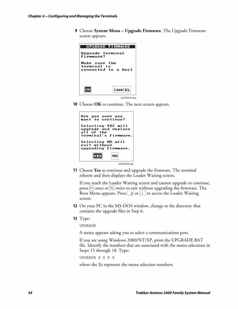
Chapter 2—Configuring and Managing the Terminals
34 Trakker Antares 2400 Family System Manual
9 Choose System Menu > Upgrade Firmware. The Upgrade Firmware screen appears.
UPGRADE FIRMWARE
Upgrade terminalfirmware?
Make sure theterminal isconnected to a host
24XXS035.eps
CANCELOK
10 Choose OK to continue. The next screen appears.
Are you sure youwant to continue?
Selecting YES willupgrade and replaceall of theterminal's firmware.
Selecting NO willexit withoutupgrading firmware.
24XXS036.eps
NOYESYES
11 Choose Yes to continue and upgrade the firmware. The terminal reboots and then displays the Loader Waiting screen.
If you reach the Loader Waiting screen and cannot upgrade or continue, press d once or œ twice to exit without upgrading the firmware. The Boot Menu appears. Press 2 or L to access the Loader Waiting screen.
12 On your PC in the MS-DOS window, change to the directory that contains the upgrade files in Step 6.
13 Type:
UPGRADE
A menu appears asking you to select a communications port.
If you are using Windows 2000/NT/XP, print the UPGRADE.BAT file. Identify the numbers that are associated with the menu selections in Steps 15 through 18. Type:
UPGRADE X X X X
where the Xs represent the menu selection numbers.
Chapter 2—Configuring and Managing the Terminals
Trakker Antares 2400 Family System Manual 35
14 Select a communications port:
Type This Value Communications Port
1 COM1
2 COM2
3 COM3
4 COM4
A menu appears asking you to select a download speed.
15 Select a download speed:
Type This Value Download Speed
1 9600 baud
2 19200 baud
3 38400 baud
4 57600 baud
5 115200 baud
A menu appears asking you to select which protocol stack to use.
16 Select a protocol stack:
Type This Value Protocol Stack
1 UDP Plus
2 TCP/IP
3 Batch/Serial
4 WTP
A menu appears asking you to select the communication hardware for your terminal.
17 Select the communications hardware:
Type This Value Communications Hardware
1 OpenAir radio
2 802.11b radio
3 Ethernet
4 802.11b radio and 802.1x TTLS security
5 802.11b radio and 802.1x LEAP security
Note: You can only select 802.11b radio and TTLS or LEAP security if you selected TCP/IP in Step 17 and you have either the 802.1x security option or the 4MB flash memory.
The Loader screen appears and begins downloading the firmware and application to the terminal.
Chapter 2—Configuring and Managing the Terminals
36 Trakker Antares 2400 Family System Manual
18 When you are done upgrading the firmware, the terminal returns to its default configuration. You will need to reconfigure the terminal. For help, see “How to Configure the Terminals” on page 12.
19 If necessary, reload your custom applications and files on the terminal. For help, see “Using the Serial Port to Transfer Applications and Files” on page 55.
To upgrade the firmware using the Trakker Antares Firmware Upgrade Utility
Note: Make sure you back up your custom files and applications, such as TE 2000, dcBrowser, and ROM-DOS, so that you can reinstall them after the upgrade procedure. For help, see “Using the Serial Port to Transfer Applications and Files” on page 55.
1 The Trakker Antares Firmware Upgrade Utility is included with the firmware upgrade. Install the utility (TAUPGRADE.EXE) on your PC.
2 Use the online help that ships with the utility to upgrade the firmware on your terminal.
3 If necessary, reload your custom applications and files on the terminal. For help, see “Using the Serial Port to Transfer Applications and Files” on page 55.
Loading Double-Byte Fonts If you ordered the optional 4MB flash drive (drive D), you can order a double-byte font and load the font on your terminal. To order a double-byte font, contact your local Intermec representative.
Note: Double-byte fonts are not available for terminals with the 802.1x security option.
You can also order the Thai language font as a configuration option for the Trakker Antares 2400 Family. For help, contact your local Intermec representative. Use the next table to determine which file name you need.
Double-Byte Fonts
Language File Name
Simplified Chinese, VT 24DBCSCT.FON
Simplified Chinese, 5250 24DBCSCL.FON
Japanese EUC (unix), VT 24DBCSJT.FON
Japanese, 5250 24DBCSJL.FON
Korean, VT 24DBCSKT.FON
Korean, 5250 24DBCSKL.FON
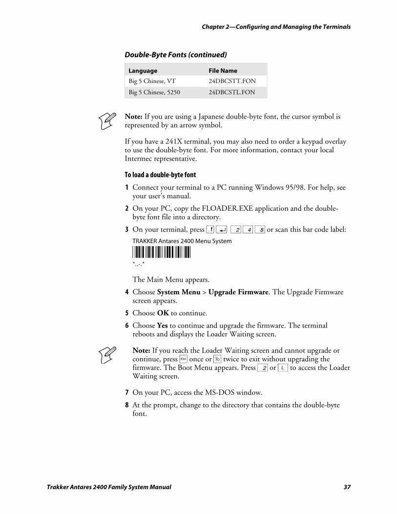
Chapter 2—Configuring and Managing the Terminals
Trakker Antares 2400 Family System Manual 37
Double-Byte Fonts (continued)
Language File Name
Big 5 Chinese, VT 24DBCSTT.FON
Big 5 Chinese, 5250 24DBCSTL.FON
Note: If you are using a Japanese double-byte font, the cursor symbol is represented by an arrow symbol.
If you have a 241X terminal, you may also need to order a keypad overlay to use the double-byte font. For more information, contact your local Intermec representative.
To load a double-byte font
1 Connect your terminal to a PC running Windows 95/98. For help, see your user’s manual.
2 On your PC, copy the FLOADER.EXE application and the double-byte font file into a directory.
3 On your terminal, press ) ; 2 4 8 or scan this bar code label:
TRAKKER Antares 2400 Menu System
*..-.* *..-.*
The Main Menu appears.
4 Choose System Menu > Upgrade Firmware. The Upgrade Firmware screen appears.
5 Choose OK to continue.
6 Choose Yes to continue and upgrade the firmware. The terminal reboots and displays the Loader Waiting screen.
Note: If you reach the Loader Waiting screen and cannot upgrade or continue, press d once or œ twice to exit without upgrading the firmware. The Boot Menu appears. Press 2 or L to access the Loader Waiting screen.
7 On your PC, access the MS-DOS window.
8 At the prompt, change to the directory that contains the double-byte font.
Chapter 2—Configuring and Managing the Terminals
38 Trakker Antares 2400 Family System Manual
9 Type:
FLOADER /COMn /baudrate filename.FON
where:
baudrate is b9600, b19200, b38400, b57600, or b115200.
filename is one of the file names in the table.
n is the number of the COM port. The font is downloaded to your terminal.
10 On your terminal, press d to exit the Loader Waiting screen, and press 1 or B to boot the terminal.
Managing Your Terminals with Wavelink Avalanche You can manage Trakker Antares terminals with firmware version 8.01 or later with the Wavelink Avalanche client management system.
This section provides a brief overview of Wavelink Avalanche and describes how it interacts with your Trakker Antares terminal. To learn more about how to use Wavelink Avalanche in your data collection network, see the Wavelink Avalanche documentation and online help.
Learning About Wavelink Avalanche To use Wavelink Avalanche, you need:
• Wavelink Avalanche Manager version 3.0 or later.
• Trakker Antares RF terminal (TCP/IP or UDP Plus) with firmware version 8.01 or later.
The Wavelink Avalanche system uses three main components to help you easily manage your terminals and other devices.
Wavelink Avalanche Components
Component Description
Enabler Resides on all devices managed by the Avalanche system. It communicates information about the device to the Avalanche Agent and manages software applications on the device.
Agent Automatically detects and upgrades all devices in the Wavelink Avalanche system and manages the daily processing functions.
Console The administrative user interface that lets you configure and communicate with the Agent. From the Console, you can configure and monitor devices and build and install software packages and software collections.
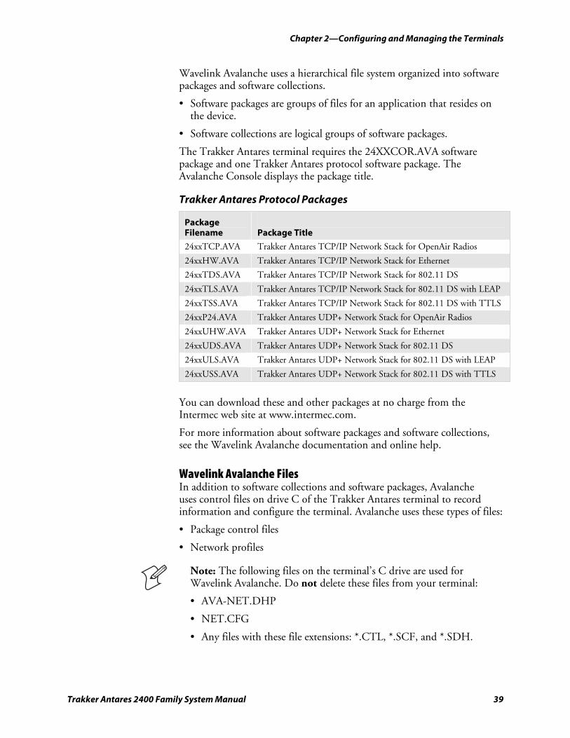
Chapter 2—Configuring and Managing the Terminals
Trakker Antares 2400 Family System Manual 39
Wavelink Avalanche uses a hierarchical file system organized into software packages and software collections.
• Software packages are groups of files for an application that resides on the device.
• Software collections are logical groups of software packages.
The Trakker Antares terminal requires the 24XXCOR.AVA software package and one Trakker Antares protocol software package. The Avalanche Console displays the package title.
Trakker Antares Protocol Packages
Package Filename
Package Title
24xxTCP.AVA Trakker Antares TCP/IP Network Stack for OpenAir Radios
24xxHW.AVA Trakker Antares TCP/IP Network Stack for Ethernet
24xxTDS.AVA Trakker Antares TCP/IP Network Stack for 802.11 DS
24xxTLS.AVA Trakker Antares TCP/IP Network Stack for 802.11 DS with LEAP
24xxTSS.AVA Trakker Antares TCP/IP Network Stack for 802.11 DS with TTLS
24xxP24.AVA Trakker Antares UDP+ Network Stack for OpenAir Radios
24xxUHW.AVA Trakker Antares UDP+ Network Stack for Ethernet
24xxUDS.AVA Trakker Antares UDP+ Network Stack for 802.11 DS
24xxULS.AVA Trakker Antares UDP+ Network Stack for 802.11 DS with LEAP
24xxUSS.AVA Trakker Antares UDP+ Network Stack for 802.11 DS with TTLS
You can download these and other packages at no charge from the Intermec web site at www.intermec.com.
For more information about software packages and software collections, see the Wavelink Avalanche documentation and online help.
Wavelink Avalanche Files In addition to software collections and software packages, Avalanche uses control files on drive C of the Trakker Antares terminal to record information and configure the terminal. Avalanche uses these types of files:
• Package control files
• Network profiles
Note: The following files on the terminal’s C drive are used for Wavelink Avalanche. Do not delete these files from your terminal:
• AVA-NET.DHP
• NET.CFG
• Any files with these file extensions: *.CTL, *.SCF, and *.SDH.
Chapter 2—Configuring and Managing the Terminals
40 Trakker Antares 2400 Family System Manual
Additionally, these types of files are used by the Trakker Antares terminals:
• Reader command files
• Firmware upgrade files
Package Control Files A package control file is automatically created for each package downloaded to the terminal. The Avalanche Agent uses control files to track which packages are installed on the client and version information about the package. If you delete a .CTL file on the client and reboot, the corresponding package is re-downloaded to the terminal.
The package control file assumes the name of the downloaded package with .CTL as the file extension. However, there is one exception: data sent with network profile information is represented by a special control file named _IPCFG.CTL.
Network Profiles A network profile is a collection of settings that lets you download certain network parameters to the terminal. Intermec recommends that you use network profiles to help manage your terminals. When a network profile is enabled, the Avalanche Agent downloads a file named AVA-NET.DHP to the terminal. The Enabler processes the file and renames it with an .SDH file extension. If an .SDH file with the same name is already present, it is replaced by the new .SDH file.
When you upgrade the terminal with a Trakker Antares firmware upgrade package, all .SDH files on the terminal are renamed with the .DHP file extension so that they can be reprocessed to restore the configuration.
Reader Command Files Reader command files are text-based files (.RCD) that can contain any Trakker Antares reader or configuration command.
A reader command file can be included in any package and is processed after the package is downloaded to the terminal. When the terminal processes reader command files, it scans for and processes all .RCD files.
Reader command files have an .RCD file extension. After the reader command file is processed, it is renamed with an .SCF file extension. If an .SCF file with the same name is already present, it is replaced by the new .SCF file.
When you upgrade the terminal with a Trakker Antares firmware upgrade package, all .SCF files on the terminal are renamed with the .RCD file extension so that they can be reprocessed to restore the configuration.
Chapter 2—Configuring and Managing the Terminals
Trakker Antares 2400 Family System Manual 41
When creating .RCD files, note that:
• almost any Trakker Antares command can be included in an .RCD file.
Note: The Command Processing configuration command lets you disable or enable multiple commands. Do not send the Disable All Reader Commands command to the terminal in an .RCD file.
• commands that cause the terminal to reboot are processed last (after all file processing is complete).
• any line that starts with a pound sign (#) or semicolon (;) is treated as a comment line.
• blank lines are allowed and are not processed.
• you need to include an .RCD filed named app_name.RCD for your applications. This .RCD file includes a single line of code:
//program.bin
that causes your application to run.
Upgrade Files The Trakker Antares firmware upgrade package includes special files used to upgrade firmware. The Enabler uses C:SYS_BLK.BIN and C:BLOCK3.BIN to reprogram flash blocks in firmware.
The Trakker Antares protocol upgrade packages include C:_LST_FLE.TXT. The Enabler uses C:_LST_FLE.TXT to update the list of applications loaded on the terminal.
Configuration changes that are made manually are lost when the terminal is upgraded.
Synchronization Properties and Selection Criteria The Avalanche Agent uses specific parameters to synchronize with the Enabler on your Trakker Antares terminal. These parameters can also be used as selection criteria to determine which devices to send updates and downloads to.
Synchronization Properties
Property Description and Values
IP Current IP address
Series I (for Intermec)
ModelName ITCxxxx
where xxxx is the model of the Trakker Antares terminal, such as 2415.
ModelCode Last two digits of the terminal model number. For example, 15 indicates the 2415.
Rows Number of rows displayed while Avalanche is running
Chapter 2—Configuring and Managing the Terminals
42 Trakker Antares 2400 Family System Manual
Synchronization Properties (continued)
Property Description and Values
Columns Number of columns displayed while Avalanche is running
KeyboardName Keypad Type configuration command name that identifies the keypad overlay
KeyboardCode Keypad Type configuration command binary value that identifies the keypad overlay
The Avalanche Enabler on the Trakker Antares terminals defines additional properties that can be used as selection criteria. These properties appear in the Avalanche Console only after you synchronize with the Enabler on your Trakker Antares terminal.
Trakker Antares Enabler Properties
Property Description and Values PROTOCOL UDP UDP Plus protocol
TCP TCP/IP protocol NIC 1 OpenAir
2 802.11DS
3 Ethernet
4 802.11DS with TTLS
5 802.11DS with LEAP
FirmwareVersion 6-digit firmware version number. For example, firmware version 8.01 is represented as 080100.
Learning About Intermec Settings (ICCU) Intermec Settings (ICCU ) is a proprietary Intermec application that allows you to easily configure multiple Trakker Antares terminals. Intermec Settings is available as part of a Wavelink Avalanche package (24XXRCD). You can download the Intermec Settings package at no charge from the Intermec web site at www.intermec.com.
To configure your terminals using Intermec Settings
1 From the tree view in the Avalanche Console, expand localhost > Software Collections > Antares Configuration.
2 Right-click the 24XXRCD package, and select Configure Package > Configure Firmware. The Intermec Settings application starts.
3 Use Intermec Settings to select your configuration parameters.
4 From the File menu, select Save Settings. Your configuration settings are now saved to the 24XXRCD configuration package.
5 Close the Intermec Settings window.
Chapter 2—Configuring and Managing the Terminals
Trakker Antares 2400 Family System Manual 43
6 Download the package to the terminals you want to configure.
For more information, see the online help that ships with Intermec Settings.

Chapter 2—Configuring and Managing the Terminals
44 Trakker Antares 2400 Family System Manual
Trakker Antares 2400 Family System Manual 45
Developing and Using Applications
This chapter explains how to create, download, and run applications on the programmable terminals and covers these topics:
• About the Trakker Antares programmable terminals
• Creating applications for the terminal
• How to download applications
• Using the serial port to transfer applications and files
• Using the DCS 300 to download applications and files
• Running applications on the terminal
3
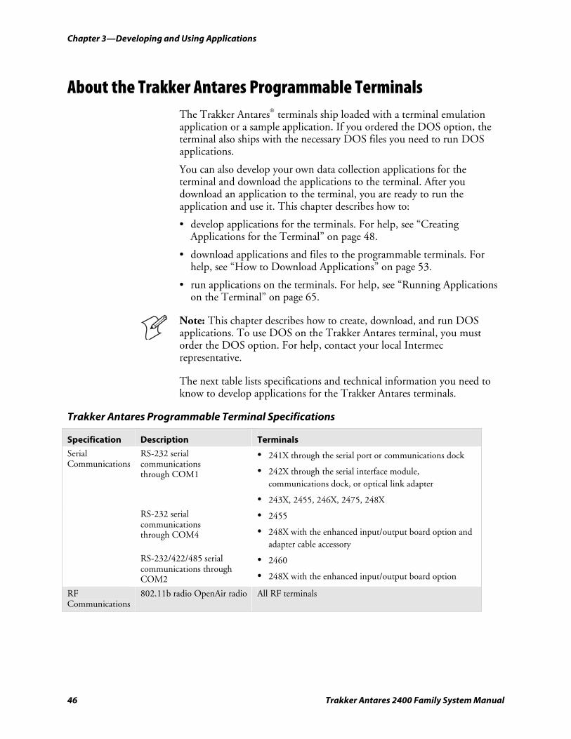
Chapter 3—Developing and Using Applications
46 Trakker Antares 2400 Family System Manual
About the Trakker Antares Programmable Terminals The Trakker Antares® terminals ship loaded with a terminal emulation application or a sample application. If you ordered the DOS option, the terminal also ships with the necessary DOS files you need to run DOS applications.
You can also develop your own data collection applications for the terminal and download the applications to the terminal. After you download an application to the terminal, you are ready to run the application and use it. This chapter describes how to:
• develop applications for the terminals. For help, see “Creating Applications for the Terminal” on page 48.
• download applications and files to the programmable terminals. For help, see “How to Download Applications” on page 53.
• run applications on the terminals. For help, see “Running Applications on the Terminal” on page 65.
Note: This chapter describes how to create, download, and run DOS applications. To use DOS on the Trakker Antares terminal, you must order the DOS option. For help, contact your local Intermec representative.
The next table lists specifications and technical information you need to know to develop applications for the Trakker Antares terminals.
Trakker Antares Programmable Terminal Specifications
Specification Description Terminals
Serial Communications
RS-232 serial communications through COM1
• 241X through the serial port or communications dock
• 242X through the serial interface module, communications dock, or optical link adapter
• 243X, 2455, 246X, 2475, 248X
RS-232 serial communications through COM4
• 2455
• 248X with the enhanced input/output board option and adapter cable accessory
RS-232/422/485 serial communications through COM2
• 2460
• 248X with the enhanced input/output board option
RF Communications
802.11b radio OpenAir radio All RF terminals
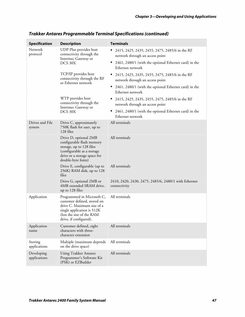
Chapter 3—Developing and Using Applications
Trakker Antares 2400 Family System Manual 47
Trakker Antares Programmable Terminal Specifications (continued)
Specification Description Terminals
Network protocol
UDP Plus provides host connectivity through the Intermec Gateway or DCS 30X
• 2415, 2425, 2435, 2455, 2475, 2485/6 in the RF network through an access point
• 2461, 2480/1 (with the optional Ethernet card) in the Ethernet network
TCP/IP provides host connectivity through the RF or Ethernet network
• 2415, 2425, 2435, 2455, 2475, 2485/6 in the RF network through an access point
• 2461, 2480/1 (with the optional Ethernet card) in the Ethernet network
WTP provides host connectivity through the Intermec Gateway or DCS 30X
• 2415, 2425, 2435, 2455, 2475, 2485/6 in the RF network through an access point
• 2461, 2480/1 (with the optional Ethernet card) in the Ethernet network
Drives and File system
Drive C, approximately 750K flash for user, up to 128 files
All terminals
Drive D, optional 2MB configurable flash memory storage, up to 128 files (configurable as a storage drive or a storage space for double-byte fonts)
All terminals
Drive E, configurable (up to 256K) RAM disk, up to 128 files
All terminals
Drive G, optional 2MB or 4MB extended SRAM drive, up to 128 files
2410, 2420, 2430, 2475, 2485/6, 2480/1 with Ethernet connectivity
Application Programmed in Microsoft C, customer defined, stored on drive C. Maximum size of a single application is 512K (less the size of the RAM drive, if configured).
All terminals
Application name
Customer defined, eight characters with three-character extension
All terminals
Storing applications
Multiple (maximum depends on the drive space)
All terminals
Developing applications
Using Trakker Antares Programmer’s Software Kit (PSK) or EZBuilder
All terminals
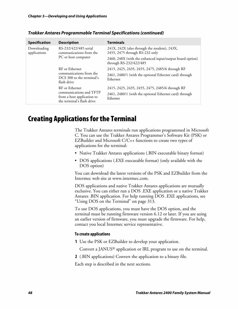
Chapter 3—Developing and Using Applications
48 Trakker Antares 2400 Family System Manual
Trakker Antares Programmable Terminal Specifications (continued)
Specification Description Terminals
Downloading applications
RS-232/422/485 serial communications from the PC or host computer
241X, 242X (also through the modem), 243X, 2455, 2475 through RS-232 only
2460, 248X (with the enhanced input/output board option) through RS-232/422/485
RF or Ethernet communications from the DCS 300 to the terminal’s flash drive
2415, 2425, 2435, 2455, 2475, 2485/6 through RF
2461, 2480/1 (with the optional Ethernet card) through Ethernet
RF or Ethernet communications and TFTP from a host application to the terminal’s flash drive
2415, 2425, 2435, 2455, 2475, 2485/6 through RF
2461, 2480/1 (with the optional Ethernet card) through Ethernet
Creating Applications for the Terminal The Trakker Antares terminals run applications programmed in Microsoft C. You can use the Trakker Antares Programmer’s Software Kit (PSK) or EZBuilder and Microsoft C/C++ functions to create two types of applications for the terminal:
• Native Trakker Antares applications (.BIN executable binary format)
• DOS applications (.EXE executable format) (only available with the DOS option)
You can download the latest versions of the PSK and EZBuilder from the Intermec web site at www.intermec.com.
DOS applications and native Trakker Antares applications are mutually exclusive. You can either run a DOS .EXE application or a native Trakker Antares .BIN application. For help running DOS .EXE applications, see “Using DOS on the Terminal” on page 313.
To use DOS applications, you must have the DOS option, and the terminal must be running firmware version 6.12 or later. If you are using an earlier version of firmware, you must upgrade the firmware. For help, contact you local Intermec service representative.
To create applications
1 Use the PSK or EZBuilder to develop your application.
Convert a JANUS® application or IRL program to use on the terminal.
2 (.BIN applications) Convert the application to a binary file.
Each step is described in the next sections.
Chapter 3—Developing and Using Applications
Trakker Antares 2400 Family System Manual 49
Note: You build your applications differently for terminals running .BIN applications and terminals running DOS .EXE applications. For help, see the Trakker Antares Application Development Tools System Manual (P/N 064433).
Using the PSK or EZBuilder to Develop Applications Intermec has two development tools, the Trakker Antares PSK and EZBuilder, which you can use to create applications for the terminals.
Developing Applications Using the PSK You can download the latest version of the PSK at no charge from the Intermec web site at www.intermec.com. This kit has a full set of programming tools to help you create applications for the terminal:
• Programmer’s Software Kit (PSK)
• Application Simulator
• FileCopy utility
• Sample programs and Make files
In addition to the PSK, you also need an Intermec-certified 16-bit C/C++ compiler, such as Microsoft Visual C/C++. For help, see your Intermec sales representative.
Note: You must use the Trakker Antares PSK version 4.2 or later to create DOS applications. To support DOS .EXE applications, some PSK library functions were moved from the IM24LIB library to the LLIBCA library. The IM24LIB library contains Intermec-specific functions.
The PSK is a library of C functions that control the Trakker Antares programmable terminals. You can program the terminal to display prompts and error messages, to collect and display data, and to transmit data to an upline Intermec Gateway, DCS 30X, or host computer. The PSK functions work with most standard Microsoft C functions. You can create complex applications that collect, store, manipulate, and transmit data to meet your system needs.
The Application Simulator is a terminate-and-stay resident (TSR) program that lets you debug and run Trakker Antares applications on a DOS or Windows PC. The Simulator captures the PSK and C functions and makes the PC mimic a Trakker Antares terminal.
Developing Applications Using EZBuilder EZBuilder (P/N 066381) is a software code generator product that provides programmers and technically oriented non-programmers with a quick and easy way to create applications for the Trakker Antares terminal.
Chapter 3—Developing and Using Applications
50 Trakker Antares 2400 Family System Manual
EZBuilder contains these items:
• EZBuilder software
• Intermec certified 16-bit C/C++ compiler
• Application Simulator
• PSK libraries
• FileCopy utility
• Sample EZBuilder programs
• EZBuilder Getting Started Guide (P/N 066450)
• EZBuilder Tutorial (P/N 066449)
Using EZBuilder, you enter simple commands to create menus, screens, and transactions and to define menu items, labels, and data fields. You can also set attributes, define function keys, and specify other processing, such as calculations, for the application. After you define the application, EZBuilder generates the program code for the application. The Application Simulator mimics a Trakker Antares terminal and lets you test the application on your computer.
Converting JANUS Applications and IRL Programs You can modify a JANUS application or an IRL program to run on your Trakker Antares terminal.
Converting Applications Between JANUS and Trakker Antares You can develop applications that run on both the JANUS devices and the Trakker Antares terminals. However, there are some differences that you need to plan for in your applications. The Trakker Antares is an intelligent terminal. A JANUS device is a DOS-compatible computer. Because of these differences, there are some features and functions that are different between the JANUS PSK and the Trakker Antares PSK.
In general, a C/C++ application written for Trakker Antares terminals requires minor changes to run on a JANUS device. However, an application written for a JANUS device may require more changes to work properly on a Trakker Antares terminal. JANUS applications developed with the JANUS PSK and compiler libraries are relatively easy to convert to an application for the Trakker Antares terminals.
There are several methods you can use to convert applications to and from JANUS devices and Trakker Antares terminals. For help with converting applications, see the Trakker Antares Application Development Tools System Manual.
Chapter 3—Developing and Using Applications
Trakker Antares 2400 Family System Manual 51
Converting IRL Programs Between the 95XX and Trakker Antares The Trakker Antares terminals and the 95XX terminals run different types of applications. The Trakker Antares terminals can run Microsoft C/C++ applications while the 95XX terminals run IRL (Intermec Reader Language) programs.
The Trakker Antares terminals support IRL by using IRL to C conversion programs. You can convert IRL programs to Microsoft C/C++ applications that use the Trakker Antares PSK functions. For information about converting IRL programs, contact your local Intermec service representative.
You can also convert your IRL program by developing a new C/C++ application using the Trakker Antares Programmer’s Software Kit or EZBuilder and Microsoft C/C++ functions.
If you are using a 2460 or a 248X with the enhanced input/output board option in a CrossBar network, the application needs to send and receive data through COM2. After your application is converted, you can download the application to the terminal and begin using it in your network.
Converting the Application to a Binary File If you ordered the DOS option, you can download the executable (.EXE) file to your terminal and run the DOS .EXE application. However, if you want to run a native Trakker Antares application, you must store it as a binary file (.BIN). You can convert a native Trakker Antares application from an .EXE file to a .BIN file using one of the following methods:
• If you use EZBuilder to create the application, specify a file format (.EXE or .BIN) in the Build Options dialog box before you build the application.
• Use the FileCopy utility to convert the .EXE file to a .BIN file when you download the file. For help, see “Using the Serial Port to Transfer Applications and Files” on page 55.
• Use the EXE2ABS.EXE program that comes with the Trakker Antares PSK or EZBuilder to convert the file.
This section explains how to use the EXE2ABS.EXE program to convert an executable file (.EXE) to an executable binary file (.BIN).
To convert an executable file to a binary file using EXE2ABS.EXE
1 Use the Trakker Antares PSK or EZBuilder to develop the application.
2 Convert the application from an executable file to a binary file by typing this command on your development PC:
drive:\intermec\im24\lib\exe2abs filename.exe
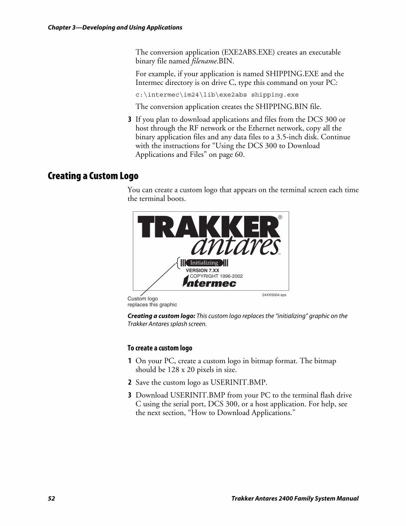
Chapter 3—Developing and Using Applications
52 Trakker Antares 2400 Family System Manual
The conversion application (EXE2ABS.EXE) creates an executable binary file named filename.BIN.
For example, if your application is named SHIPPING.EXE and the Intermec directory is on drive C, type this command on your PC:
c:\intermec\im24\lib\exe2abs shipping.exe
The conversion application creates the SHIPPING.BIN file.
3 If you plan to download applications and files from the DCS 300 or host through the RF network or the Ethernet network, copy all the binary application files and any data files to a 3.5-inch disk. Continue with the instructions for “Using the DCS 300 to Download Applications and Files” on page 60.
Creating a Custom Logo You can create a custom logo that appears on the terminal screen each time the terminal boots.
VERSION 7.XX COPYRIGHT 1996-2002
24XXS004.epsCustom logoreplaces this graphic
Creating a custom logo: This custom logo replaces the “initializing” graphic on the Trakker Antares splash screen.
To create a custom logo
1 On your PC, create a custom logo in bitmap format. The bitmap should be 128 x 20 pixels in size.
2 Save the custom logo as USERINIT.BMP.
3 Download USERINIT.BMP from your PC to the terminal flash drive C using the serial port, DCS 300, or a host application. For help, see the next section, “How to Download Applications.”
Chapter 3—Developing and Using Applications
Trakker Antares 2400 Family System Manual 53
How to Download Applications You can download applications and files to the programmable terminals by using any of the following methods:
• Serial port
• DCS 300
• Host application
These methods are described in the next procedures.
You can also use reader commands to transfer files. For help, see “Transmit File” on page 116 and “Receive File” on page 105. To learn how to run applications on the terminal, see “Running Applications on the Terminal” on page 65.
Use a serial port to download applications and files to the terminal
1 Create your applications using the Trakker Antares Programmer’s Software Kit (PSK) or EZBuilder. For help, see “Creating Applications for the Terminal” on page 48.
2 (.BIN applications) Convert each application to a binary file.
• Use the PSK utility EXE2ABS.EXE. For help, see “Converting the Application to a Binary File” on page 51.
• Use FileCopy or EZBuilder.
3 Connect the terminal’s serial port to the host computer or PC. For help, see your terminal user’s manual.
4 Use the FileCopy utility, VIEW246X.EXE, or LOADER.EXE on the host computer or PC to download applications and files to the terminal. For help, see “Using the Serial Port to Transfer Applications and Files” on page 55.
5 (.BIN applications) Use the TRAKKER Antares 2400 Menu System to load and run an application. For help, see “Running Applications on the Terminal” on page 65.
6 (DOS .EXE applications) If you ordered the DOS option, start DOS on the terminal and run a DOS application. For help, see “Using DOS on the Terminal” on page 313.
Chapter 3—Developing and Using Applications
54 Trakker Antares 2400 Family System Manual
Use the DCS 300 to download applications and files to the terminal
1 Create your applications using the Trakker Antares PSK or EZBuilder. For help, see “Creating Applications for the Terminal” on page 48.
2 (.BIN applications) Convert each application to a binary file.
• Use the PSK utility EXE2ABS.EXE. For help, see “Converting the Application to a Binary File” on page 51.
• Use FileCopy or EZBuilder.
3 Copy the applications and files to the DCS 300. For help, see “Copying Applications and Files to the DCS 300” on page 61.
4 Use the Download Server feature on the DCS 300 to download applications and files to the terminal. For help, see “Downloading Applications and Files to the Terminal” on page 62.
5 (.BIN applications) Use the TRAKKER Antares 2400 Menu System to load and run an application. For help, see “Running Applications on the Terminal” on page 65.
6 (DOS .EXE applications) If you ordered the DOS option, start DOS on the terminal and run a DOS application. For help, see “Using DOS on the Terminal” on page 313.
Use a host application to download applications and files to the terminal
1 Create your applications using the Trakker Antares PSK or EZBuilder. For help, see “Creating Applications for the Terminal” on page 48.
2 (.BIN applications) Convert each application to a binary file.
• Use the PSK utility EXE2ABS.EXE. For help, see “Converting the Application to a Binary File” on page 51.
• Use FileCopy or EZBuilder.
3 Copy the applications and files to the host.
4 Write a host application that can communicate with the terminal directly through an access point or through the Ethernet network. Use the host application to download applications and files to the terminal. For help, see “Transferring Files and Data in a TCP/IP Direct Connect Network” on page 24.
5 (.BIN applications) Use the TRAKKER Antares 2400 Menu System to load and run an application. For help, see “Running Applications on the Terminal” on page 65.
Use the host application to send the Run Program command.
6 (DOS .EXE applications) If you ordered the DOS option, start DOS on the terminal and run a DOS application. For help, see “Using DOS on the Terminal” on page 313.
Chapter 3—Developing and Using Applications
Trakker Antares 2400 Family System Manual 55
Using the Serial Port to Transfer Applications and Files You can download or upload applications and files between a PC or host computer and the terminal using serial communications. For help connecting the terminal, see your terminal user’s manual. Once the terminal is connected, you can transfer files to or from the terminal using one of the following methods:
• Use the FileCopy utility that ships with the Trakker Antares Programmer’s Software Kit (PSK) and EZBuilder to copy files to and from the terminal. This utility is also available at no charge from the Intermec web site at www.intermec.com.
• Use the VIEW246X.EXE program that comes with the firmware upgrade software to copy files to and from the terminal. You also need the FLASHLDR.BIN file that comes with the firmware upgrade software.
• Use the LOADER.EXE program that comes with the firmware upgrade software to copy files to the terminal.
• Use the EZBuilder “download” tool. For help, see the EZBuilder online help.
• Use the Receive File or Transmit File reader commands. For help, see “Transmit File” on page 116 and “Receive File” on page 105.
• (2460 terminal or 248X terminal with enhanced input/output board option only) Use the following reader commands to download an application through the 9154 or 9161 controller to a 2460 or 248X in a CrossBar network:
• Receive and Convert 7-Bit ASCII Files to 8-Bit Binary Files. For help, see “Receive and Convert 7-Bit ASCII Files to 8-Bit Binary Files” on page 107.
• Transmit and Convert 8-Bit Binary Files to 7-Bit ASCII Files. For help, see “Transmit and Convert 8-Bit Binary Files to 7-Bit ASCII Files” on page 118.
This section explains:
• how to use the FileCopy utility to download or upload applications and files to or from the terminal.
• how to use the VIEW246X.EXE program to download or upload applications and files to or from the terminal.
• how to use the LOADER.EXE program to download applications to the terminal.
You can use the FileCopy utility and LOADER.EXE to download either .EXE or .BIN application files. However, to run a native Trakker Antares application on the terminal, it must be stored as an executable binary file (.BIN).
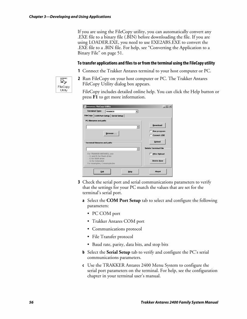
Chapter 3—Developing and Using Applications
56 Trakker Antares 2400 Family System Manual
If you are using the FileCopy utility, you can automatically convert any .EXE file to a binary file (.BIN) before downloading the file. If you are using LOADER.EXE, you need to use EXE2ABS.EXE to convert the .EXE file to a .BIN file. For help, see “Converting the Application to a Binary File” on page 51.
To transfer applications and files to or from the terminal using the FileCopy utility
1 Connect the Trakker Antares terminal to your host computer or PC.
2 Run FileCopy on your host computer or PC. The Trakker Antares FileCopy Utility dialog box appears.
FileCopy includes detailed online help. You can click the Help button or press F1 to get more information.
3 Check the serial port and serial communications parameters to verify that the settings for your PC match the values that are set for the terminal’s serial port.
a Select the COM Port Setup tab to select and configure the following parameters:
• PC COM port
• Trakker Antares COM port
• Communications protocol
• File Transfer protocol
• Baud rate, parity, data bits, and stop bits
b Select the Serial Setup tab to verify and configure the PC’s serial communications parameters.
c Use the TRAKKER Antares 2400 Menu System to configure the serial port parameters on the terminal. For help, see the configuration chapter in your terminal user’s manual.
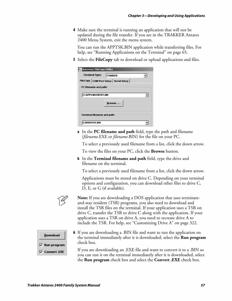
Chapter 3—Developing and Using Applications
Trakker Antares 2400 Family System Manual 57
4 Make sure the terminal is running an application that will not be updated during the file transfer. If you are in the TRAKKER Antares 2400 Menu System, exit the menu system.
You can run the APPTSK.BIN application while transferring files. For help, see “Running Applications on the Terminal” on page 65.
5 Select the FileCopy tab to download or upload applications and files.
a In the PC filename and path field, type the path and filename (filename.EXE or filename.BIN) for the file on your PC.
To select a previously used filename from a list, click the down arrow.
To view the files on your PC, click the Browse button.
b In the Terminal filename and path field, type the drive and filename on the terminal.
To select a previously used filename from a list, click the down arrow.
Applications must be stored on drive C. Depending on your terminal options and configuration, you can download other files to drive C, D, E, or G (if available).
Note: If you are downloading a DOS application that uses terminate-and-stay resident (TSR) programs, you also need to download and install the TSR files on the terminal. If your application uses a TSR on drive C, transfer the TSR to drive C along with the application. If your application uses a TSR on drive A, you need to recreate drive A to include the TSR. For help, see “Customizing Drive A” on page 322.
6 If you are downloading a .BIN file and want to run the application on the terminal immediately after it is downloaded, select the Run program check box.
If you are downloading an .EXE file and want to convert it to a .BIN so you can run it on the terminal immediately after it is downloaded, select the Run program check box and select the Convert .EXE check box.
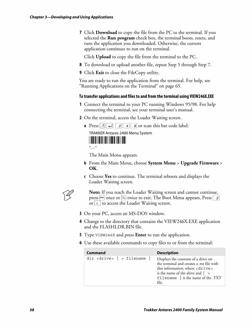
Chapter 3—Developing and Using Applications
58 Trakker Antares 2400 Family System Manual
7 Click Download to copy the file from the PC to the terminal. If you selected the Run program check box, the terminal boots, resets, and runs the application you downloaded. Otherwise, the current application continues to run on the terminal.
Click Upload to copy the file from the terminal to the PC.
8 To download or upload another file, repeat Step 5 through Step 7.
9 Click Exit to close the FileCopy utility.
You are ready to run the application from the terminal. For help, see “Running Applications on the Terminal” on page 65.
To transfer applications and files to and from the terminal using VIEW246X.EXE
1 Connect the terminal to your PC running Windows 95/98. For help connecting the terminal, see your terminal user’s manual.
2 On the terminal, access the Loader Waiting screen.
a Press ) ; 2 4 8 or scan this bar code label:
TRAKKER Antares 2400 Menu System
*..-.* *..-.*
The Main Menu appears.
b From the Main Menu, choose System Menu > Upgrade Firmware > OK.
c Choose Yes to continue. The terminal reboots and displays the Loader Waiting screen.
Note: If you reach the Loader Waiting screen and cannot continue, press • once or œ twice to exit. The Boot Menu appears. Press 2 or L to access the Loader Waiting screen.
3 On your PC, access an MS-DOS window.
4 Change to the directory that contains the VIEW246X.EXE application and the FLASHLDR.BIN file.
5 Type VIEW246X and press Enter to run the application.
6 Use these available commands to copy files to or from the terminal:
Command Description dir <drive> { > filename } Displays the contents of a drive on
the terminal and creates a .txt file with this information, where <drive> is the name of the drive and { > filename } is the name of the .TXT file.
Chapter 3—Developing and Using Applications
Trakker Antares 2400 Family System Manual 59
Commands (continued)
Command Description del term_filename Deletes a file from the terminal, where
term_filename is the name of the file.
cls Clears the screen.
copyfromterm <cf> term_filename, pc_filename
Copies a file from the terminal to the PC where term_filename is the name of the file on the terminal and pc_filename is the name that the file will be given on the PC.
Example: Type cf c:\basedate.txt d:\date.txt to copy basedate.txt from the C drive on the terminal to the D drive on the PC and rename the file date.txt.
copytoterm <ct> pc_filename, term_filename
Copies a file from the PC to the terminal where pc_filename is the name of the file on the PC and term_filename is the name that the file will be given on the terminal.
Example: Type ct d:\basedate.txt c:\basedate.txt to copy the file basedate.txt from the D drive on the PC to the C drive on the terminal.
help Displays the help screen.
quit or exit Closes the VIEW246X.EXE application.
To transfer applications and files to the terminal using LOADER.EXE
Note: Before you can transfer applications and files, you must open the MS-DOS window and open the MS-DOS Prompt Properties dialog box. In the Memory tab, set the Initial Environment field to 4096. Close the MS-DOS window and re-open it.
1 Connect the terminal to your PC. For help connecting the terminal, see your terminal user’s manual.
2 On your PC, load the application or file that you want to download.
3 Access the MS-DOS window.
4 Change to the directory that contains the LOADER.EXE program.
Chapter 3—Developing and Using Applications
60 Trakker Antares 2400 Family System Manual
5 On the terminal, access the Loader Waiting screen.
a Press ) ; 2 4 8 or scan this bar code label:
TRAKKER Antares 2400 Menu System
*..-.* *..-.*
The Main Menu appears.
b From the Main Menu, choose System Menu > Upgrade Firmware > OK.
c Choose Yes to continue. The terminal reboots and displays the Loader Waiting screen.
6 On your PC, type:
LOADER pathname\filename
where:
pathname is the path to the application or file that you want to download.
filename is the name of the application or file that you want to download.
The Loader screen appears and the file or application is transferred to the terminal.
Using the DCS 300 to Download Applications and Files You can download applications and files to an RF or Ethernet terminal using network communications. The advantage to downloading files through RF or Ethernet network communications is that you can download multiple files to one or more terminals.
You use RF or Ethernet communications to download applications from the DCS 300 to RF or Ethernet terminals running UDP Plus or WTP or from the host to RF or Ethernet terminals running TCP/IP. This section explains how to use the DCS 300 to download applications and files. For help downloading files in a TCP/IP network, see “Transferring Files and Data in a TCP/IP Direct Connect Network” on page 24.
To download applications and files from the DCS 300
1 Copy the applications and files to the DCS 300. For help see the next section, “Copying Applications and Files to the DCS 300.”
2 Use the Download Server feature on the DCS 300 to download the applications and files to the RF or Ethernet terminal. For help, see “Downloading Applications and Files to the Terminal” on page 62.
Chapter 3—Developing and Using Applications
Trakker Antares 2400 Family System Manual 61
Or, use the Receive File or Transmit File reader commands to download the applications and files to the RF or Ethernet terminal. For help, see “Transmit File” on page 116 and “Receive File” on page 105.
Each step is described in the next sections. Before you start, make sure that the RF or Ethernet terminal is communicating with the DCS 300. For help installing or configuring the network, see the networking chapter in your terminal user’s manual.
Copying Applications and Files to the DCS 300 1 Copy the applications and files to a 3.5-inch disk.
2 Insert the disk into the disk drive of the DCS 300.
3 From the main menu sidebar buttons, choose File Handling. The File Handling dialog box appears.
4 In the File Handling list box, select Restore User Files and choose OK. A message box appears telling you to insert the disk in the disk drive of the DCS 300.
5 Choose OK. The Restore User Files dialog box appears. The files on the disk appear in the Available Files list box.
6 In the Available Files list box, add all the files that you want to restore to the Selected Files list box.
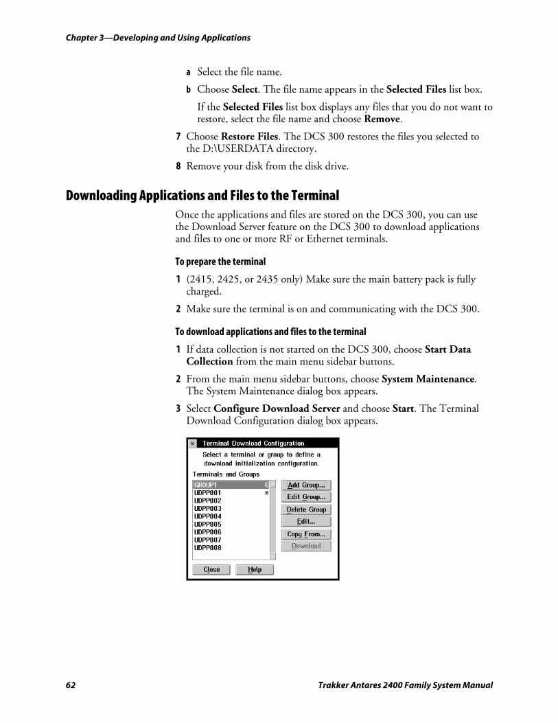
Chapter 3—Developing and Using Applications
62 Trakker Antares 2400 Family System Manual
a Select the file name.
b Choose Select. The file name appears in the Selected Files list box.
If the Selected Files list box displays any files that you do not want to restore, select the file name and choose Remove.
7 Choose Restore Files. The DCS 300 restores the files you selected to the D:\USERDATA directory.
8 Remove your disk from the disk drive.
Downloading Applications and Files to the Terminal Once the applications and files are stored on the DCS 300, you can use the Download Server feature on the DCS 300 to download applications and files to one or more RF or Ethernet terminals.
To prepare the terminal
1 (2415, 2425, or 2435 only) Make sure the main battery pack is fully charged.
2 Make sure the terminal is on and communicating with the DCS 300.
To download applications and files to the terminal
1 If data collection is not started on the DCS 300, choose Start Data Collection from the main menu sidebar buttons.
2 From the main menu sidebar buttons, choose System Maintenance. The System Maintenance dialog box appears.
3 Select Configure Download Server and choose Start. The Terminal Download Configuration dialog box appears.
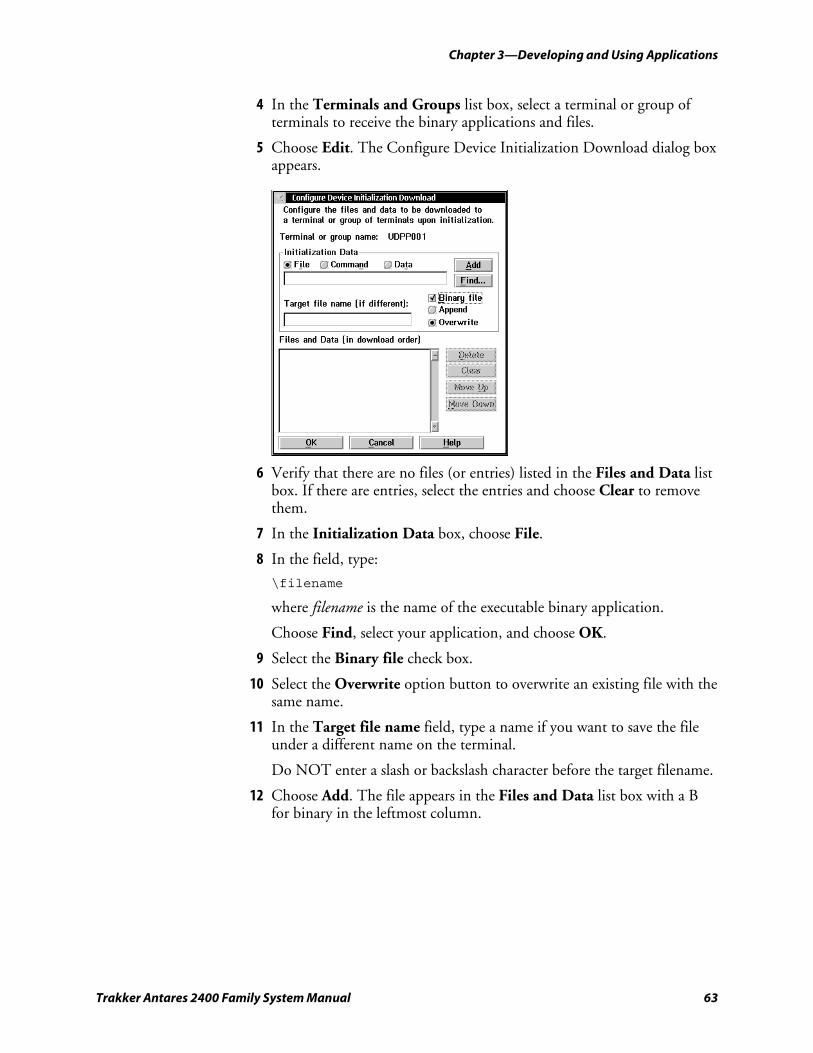
Chapter 3—Developing and Using Applications
Trakker Antares 2400 Family System Manual 63
4 In the Terminals and Groups list box, select a terminal or group of terminals to receive the binary applications and files.
5 Choose Edit. The Configure Device Initialization Download dialog box appears.
6 Verify that there are no files (or entries) listed in the Files and Data list box. If there are entries, select the entries and choose Clear to remove them.
7 In the Initialization Data box, choose File.
8 In the field, type:
\filename
where filename is the name of the executable binary application.
Choose Find, select your application, and choose OK.
9 Select the Binary file check box.
10 Select the Overwrite option button to overwrite an existing file with the same name.
11 In the Target file name field, type a name if you want to save the file under a different name on the terminal.
Do NOT enter a slash or backslash character before the target filename.
12 Choose Add. The file appears in the Files and Data list box with a B for binary in the leftmost column.
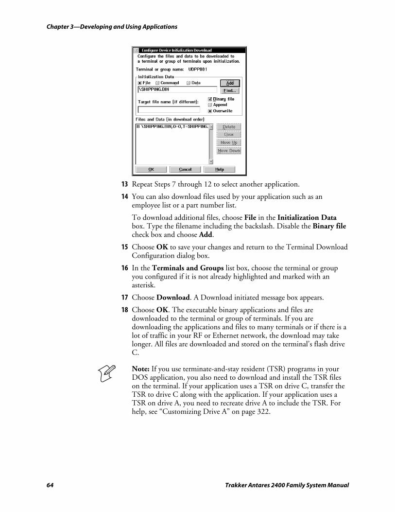
Chapter 3—Developing and Using Applications
64 Trakker Antares 2400 Family System Manual
13 Repeat Steps 7 through 12 to select another application.
14 You can also download files used by your application such as an employee list or a part number list.
To download additional files, choose File in the Initialization Data box. Type the filename including the backslash. Disable the Binary file check box and choose Add.
15 Choose OK to save your changes and return to the Terminal Download Configuration dialog box.
16 In the Terminals and Groups list box, choose the terminal or group you configured if it is not already highlighted and marked with an asterisk.
17 Choose Download. A Download initiated message box appears.
18 Choose OK. The executable binary applications and files are downloaded to the terminal or group of terminals. If you are downloading the applications and files to many terminals or if there is a lot of traffic in your RF or Ethernet network, the download may take longer. All files are downloaded and stored on the terminal’s flash drive C.
Note: If you use terminate-and-stay resident (TSR) programs in your DOS application, you also need to download and install the TSR files on the terminal. If your application uses a TSR on drive C, transfer the TSR to drive C along with the application. If your application uses a TSR on drive A, you need to recreate drive A to include the TSR. For help, see “Customizing Drive A” on page 322.
Chapter 3—Developing and Using Applications
Trakker Antares 2400 Family System Manual 65
19 Click Close to close the dialog box and return to the System Maintenance dialog box.
After you download an application to the terminal, you can run the application. For help, see the next section, “Running Applications on the Terminal.”
Running Applications on the Terminal After you download an application to the terminal, you are ready to run the application and use it. Depending on the type of application you want to run, you can use one or more of these methods:
• Use the FileCopy utility. For help, see “Using the Serial Port to Transfer Applications and Files” on page 55.
• Use the Run Program reader command. For help, see “Run Program” in on page 112.
• (DOS option only) Use DOS to run DOS applications. For help, see “Using DOS on the Terminal” on page 313.
• Use the TRAKKER Antares 2400 Menu System. For help, continue with the next procedure.
Note: You must use DOS to run DOS applications; however, once you have started DOS, you can switch between DOS and the TRAKKER Antares 2400 Menu System as needed.
To run an application on the terminal
1 Press ) ; 2 4 8 or scan this bar code label to access the TRAKKER Antares 2400 Menu System.
TRAKKER Antares 2400 Menu System
*..-.* *..-.*
The Main Menu appears.
2 Choose System Menu > File Manager. The File Manager screen appears prompting you to select a drive.
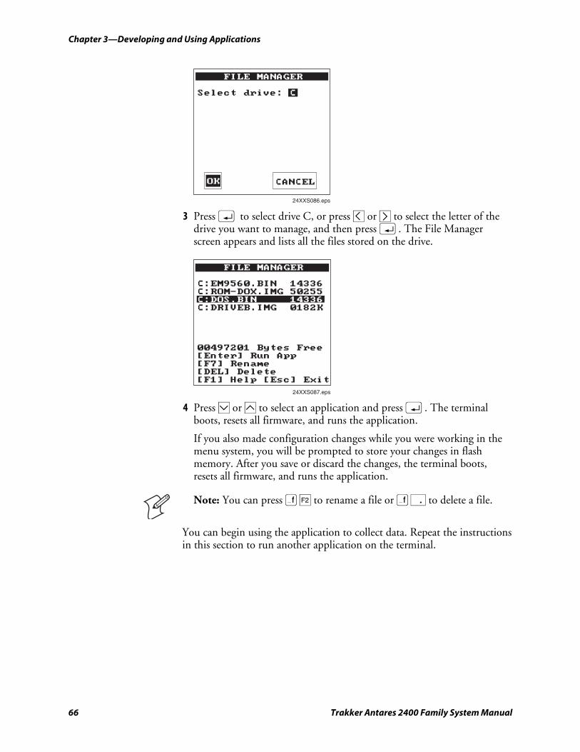
Chapter 3—Developing and Using Applications
66 Trakker Antares 2400 Family System Manual
FILE MANAGER
Select drive: C
24XXS086.eps
OK CANCEL
3 Press ; to select drive C, or press – or ª to select the letter of the drive you want to manage, and then press ;. The File Manager screen appears and lists all the files stored on the drive.
FILE MANAGER
C:EM9560.BIN 14336C:ROM-DOX.IMG 50255C:DOS.BIN 14336C:DRIVEB.IMG 0182K
00497201 Bytes Free[Enter] Run App[F7] Rename[DEL] Delete[F1] Help [Esc] Exit
24XXS087.eps
4 Press † or ¥ to select an application and press ;. The terminal boots, resets all firmware, and runs the application.
If you also made configuration changes while you were working in the menu system, you will be prompted to store your changes in flash memory. After you save or discard the changes, the terminal boots, resets all firmware, and runs the application.
Note: You can press ) ¢ to rename a file or ) . to delete a file.
You can begin using the application to collect data. Repeat the instructions in this section to run another application on the terminal.
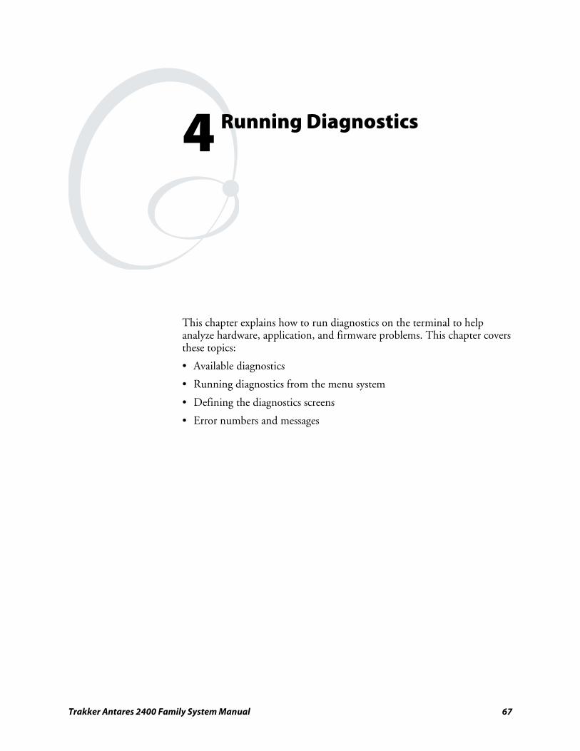
Trakker Antares 2400 Family System Manual 67
Running Diagnostics
This chapter explains how to run diagnostics on the terminal to help analyze hardware, application, and firmware problems. This chapter covers these topics:
• Available diagnostics
• Running diagnostics from the menu system
• Defining the diagnostics screens
• Error numbers and messages
4
Chapter 4—Running Diagnostics nugget 39 AGaramond
68 Trakker Antares 2400 Family System Manual
What Diagnostics Are Available? You can run diagnostics on the Trakker Antares® terminals to help analyze hardware and firmware problems, fix application problems, and view system information. You use the TRAKKER Antares 2400 Menu System to run diagnostics. This chapter lists the diagnostics in alphabetical order. Use the following tables to find the software, hardware, and system diagnostics you want to run.
Note: Diagnostics are not available on 246X terminals, because 246X terminals do not use the TRAKKER Antares 2400 Menu System.
Diagnostics Listed by Category
Hardware Diagnostic Test
Description
Page Number
Battery/PIC Status
Shows the power level of the backup battery. Indicates the backup battery’s current volts, temperature, and charging status.
Reports main board and the I/O board temperature, and the status of the EEPROM checksum and the master bus.
73
Beeper Test Sounds a series of beeps to test the beeper by using a range of beep volumes and beep frequencies.
76
Display Test Tests and turns on the pixels on the screen to make sure all areas of the screen are working correctly.
77
Hardware Configuration
Lists the terminal’s hardware components that were installed at the Intermec factory, including the RF country code.
80
Keypad Test Shows the hexadecimal, decimal, and scan code value for any key or key combination on the keyboard.
82
Radio Test (RF terminals only) Tests the radio to make sure it is working.
83
Scanner Test Tests the laser scanner to make sure it is working. 84
nugget 39 AGaramond Chapter 4—Running Diagnostics
Trakker Antares 2400 Family System Manual 69
Diagnostics Listed by Category (continued)
System Diagnostic Test
Description
Page Number
Access Point (RF terminals only) Lists information about the access point the RF terminal is communicating with across the network.
72
Application Efficiency
Displays the application efficiency percentage to help determine the impact that the application has on the terminal’s battery power.
72
Code Verify Determines if the terminal’s firmware has been overwritten.
77
Malloc Application Information
Shows how memory is allocated and used by the current application.
82
Malloc Firmware Information
Shows how memory is allocated and used in the terminal firmware.
83
Serial Port Test Tests serial communications between the terminal and the host computer or serial device.
85
Subsystem Versions
Lists the version of each major firmware subsystem loaded on the terminal.
86
Software Diagnostic Test
Description
Page Number
Application Events
Shows the current status of each application event to help debug applications.
73
Clear Task Profiles
Clears the Task Status counters so that you can begin accumulating new task statistics for the Task Status screen and the Application Efficiency screen.
76
Error Logger Lists any errors that the firmware did not expect. 78
Font Test Lists the double-byte font, if any, that is loaded in the terminal.
79
Keypad Table Lists the number of the keypad table that is loaded in the terminal.
80
Task Status Shows the task name, stack, the percentage of time each subsystem has been running, and the stack usage.
86
Running Diagnostics From the Menu System The TRAKKER Antares 2400 Menu System is a menu-driven application that lets you configure the terminal, view system information, and run diagnostics. You can access the TRAKKER Antares 2400 Menu System and run diagnostics while running any application.
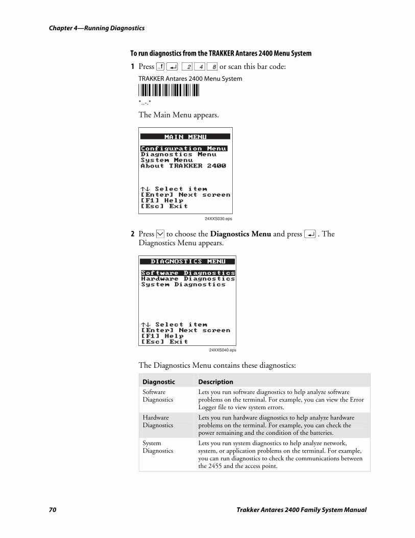
Chapter 4—Running Diagnostics nugget 39 AGaramond
70 Trakker Antares 2400 Family System Manual
To run diagnostics from the TRAKKER Antares 2400 Menu System
1 Press ) ; 2 4 8 or scan this bar code:
TRAKKER Antares 2400 Menu System
*..-.* *..-.*
The Main Menu appears.
24XXS030.eps
2 Press † to choose the Diagnostics Menu and press ;. The Diagnostics Menu appears.
DIAGNOSTICS MENU
Software DiagnosticsHardware DiagnosticsSystem Diagnostics
_` Select item[Enter] Next screen[F1] Help[Esc] Exit
24XXS040.eps
The Diagnostics Menu contains these diagnostics:
Diagnostic Description
Software Diagnostics
Lets you run software diagnostics to help analyze software problems on the terminal. For example, you can view the Error Logger file to view system errors.
Hardware Diagnostics
Lets you run hardware diagnostics to help analyze hardware problems on the terminal. For example, you can check the power remaining and the condition of the batteries.
System Diagnostics
Lets you run system diagnostics to help analyze network, system, or application problems on the terminal. For example, you can run diagnostics to check the communications between the 2455 and the access point.
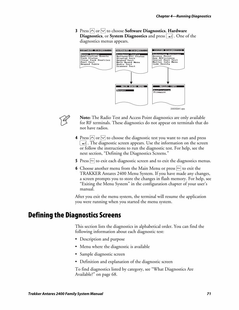
nugget 39 AGaramond Chapter 4—Running Diagnostics
Trakker Antares 2400 Family System Manual 71
3 Press ¥ or † to choose Software Diagnostics, Hardware Diagnostics, or System Diagnostics and press ;. One of the diagnostics menus appears.
SOFTWARE DIAGNOSTICS
Error LoggerApplication EventsTask StatusClear Task ProfilesFont TestKeypad Table
HARDWARE DIAGNOSTICS
Hardware ConfigBattery/PIC StatusDisplay TestKeypad TestMain Board MenuRadio TestScanner Test
SYSTEM DIAGNOSTICS
Subsystem VersionsAccess PointApp EfficiencySerial Port TestMalloc Info MenuCode Verify
MALLOC INFO
Application
Firmware
MAIN BOARD MENU
Application
Beeper
24XXS041.eps
Note: The Radio Test and Access Point diagnostics are only available for RF terminals. These diagnostics do not appear on terminals that do not have radios.
4 Press ¥ or † to choose the diagnostic test you want to run and press ;. The diagnostic screen appears. Use the information on the screen or follow the instructions to run the diagnostic test. For help, see the next section, “Defining the Diagnostics Screens.”
5 Press d to exit each diagnostic screen and to exit the diagnostics menus.
6 Choose another menu from the Main Menu or press d to exit the TRAKKER Antares 2400 Menu System. If you have made any changes, a screen prompts you to store the changes in flash memory. For help, see “Exiting the Menu System” in the configuration chapter of your user’s manual.
After you exit the menu system, the terminal will resume the application you were running when you started the menu system.
Defining the Diagnostics Screens This section lists the diagnostics in alphabetical order. You can find the following information about each diagnostic test:
• Description and purpose
• Menu where the diagnostic is available
• Sample diagnostic screen
• Definition and explanation of the diagnostic screen
To find diagnostics listed by category, see “What Diagnostics Are Available?” on page 68.
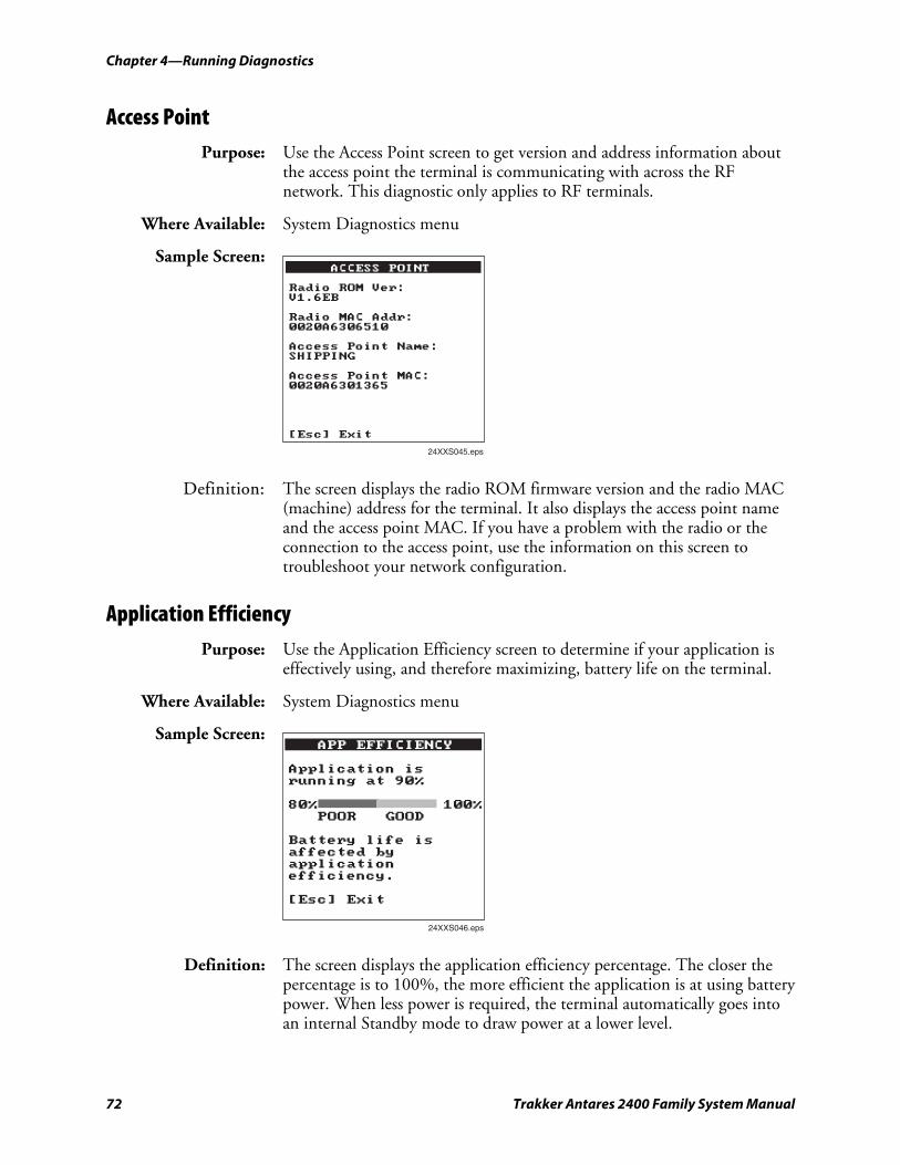
Chapter 4—Running Diagnostics nugget 39 AGaramond
72 Trakker Antares 2400 Family System Manual
Access Point Purpose: Use the Access Point screen to get version and address information about
the access point the terminal is communicating with across the RF network. This diagnostic only applies to RF terminals.
Where Available: System Diagnostics menu
Sample Screen:
24XXS045.eps
ACCESS POINT
Radio ROM Ver:V1.6EB
Radio MAC Addr:0020A6306510
Access Point Name:SHIPPING
Access Point MAC:0020A6301365
[Esc] Exit
Definition: The screen displays the radio ROM firmware version and the radio MAC (machine) address for the terminal. It also displays the access point name and the access point MAC. If you have a problem with the radio or the connection to the access point, use the information on this screen to troubleshoot your network configuration.
Application Efficiency Purpose: Use the Application Efficiency screen to determine if your application is
effectively using, and therefore maximizing, battery life on the terminal.
Where Available: System Diagnostics menu
Sample Screen: APP EFFICIENCY
Subsystem VersionsApplication isrunning at 90%
80% 100%POOR GOOD
Battery life isaffected byapplicationefficiency.
[Esc] Exit
24XXS046.eps
Definition: The screen displays the application efficiency percentage. The closer the percentage is to 100%, the more efficient the application is at using battery power. When less power is required, the terminal automatically goes into an internal Standby mode to draw power at a lower level.
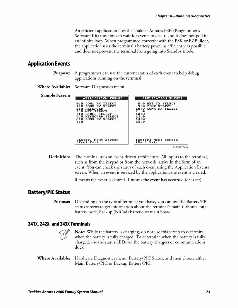
nugget 39 AGaramond Chapter 4—Running Diagnostics
Trakker Antares 2400 Family System Manual 73
An efficient application uses the Trakker Antares PSK (Programmer’s Software Kit) functions to wait for events to occur, and it does not poll in an infinite loop. When programmed correctly with the PSK or EZBuilder, the application uses the terminal’s battery power as efficiently as possible and does not prevent the terminal from going into Standby mode.
Application Events Purpose: A programmer can use the current status of each event to help debug
applications running on the terminal.
Where Available: Software Diagnostics menu.
Sample Screen: APPLICATION EVENTS
0:0 COM1 RX SELECT1:0 COM2 RX SELECT2:0 RESERVED3:0 NET SELECT4:0 LABEL SELECT5:0 KEYBOARD SELECT6:0 COM3 RX SELECT7:0
[Enter] Next screen[Esc] Exit
24XXS047.eps
APPLICATION EVENTS
8:0 NET TX SELECT9:0 TIME SELECT10:0 COM4 RX SELECT11:012:013:014:015:0
[Enter] Next screen[Esc] Exit
Definition: The terminal uses an event-driven architecture. All inputs to the terminal, such as from the keypad or from the network, arrive in the form of an event. You can check the status of each event using the Application Events screen. When an event is serviced by the application, the event is cleared.
0 means the event is cleared. 1 means the event has occurred (or is set).
Battery/PIC Status Purpose: Depending on the type of terminal you have, you can use the Battery/PIC
status screens to get information about the terminal’s main (lithium-ion) battery pack, backup (NiCad) battery, or main board.
241X, 242X, and 243X Terminals
Note: While the battery is charging, do not use this screen to determine when the battery is fully charged. To determine when the battery is fully charged, use the status LEDs on the battery chargers or communications dock.
Where Available: Hardware Diagnostics menu, Battery/PIC Status, and then choose either Main Battery/PIC or Backup Battery/PIC.
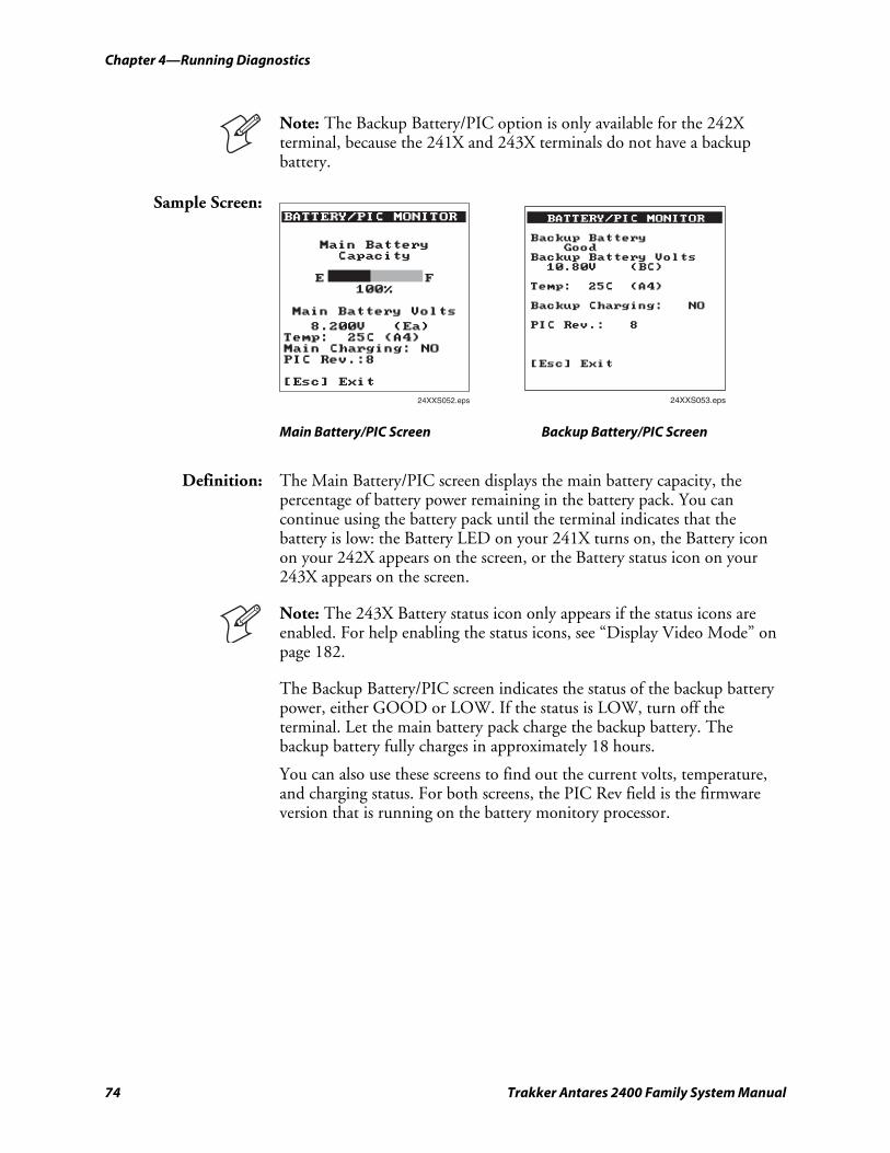
Chapter 4—Running Diagnostics nugget 39 AGaramond
74 Trakker Antares 2400 Family System Manual
Note: The Backup Battery/PIC option is only available for the 242X terminal, because the 241X and 243X terminals do not have a backup battery.
Sample Screen: BATTERY/PIC MONITOR
24XXS052.eps
Main BatteryCapacity
E F100%
Main Battery Volts
8.200V (Ea)Temp: 25C (A4)Main Charging: NOPIC Rev.:8
[Esc] Exit
24XXS053.eps
BATTERY/PIC MONITOR
Backup BatteryGood
Backup Battery Volts10.80V (BC)
Temp: 25C (A4)
Backup Charging: NO
PIC Rev.: 8
[Esc] Exit
Main Battery/PIC Screen Backup Battery/PIC Screen
Definition: The Main Battery/PIC screen displays the main battery capacity, the percentage of battery power remaining in the battery pack. You can continue using the battery pack until the terminal indicates that the battery is low: the Battery LED on your 241X turns on, the Battery icon on your 242X appears on the screen, or the Battery status icon on your 243X appears on the screen.
Note: The 243X Battery status icon only appears if the status icons are enabled. For help enabling the status icons, see “Display Video Mode” on page 182.
The Backup Battery/PIC screen indicates the status of the backup battery power, either GOOD or LOW. If the status is LOW, turn off the terminal. Let the main battery pack charge the backup battery. The backup battery fully charges in approximately 18 hours.
You can also use these screens to find out the current volts, temperature, and charging status. For both screens, the PIC Rev field is the firmware version that is running on the battery monitory processor.
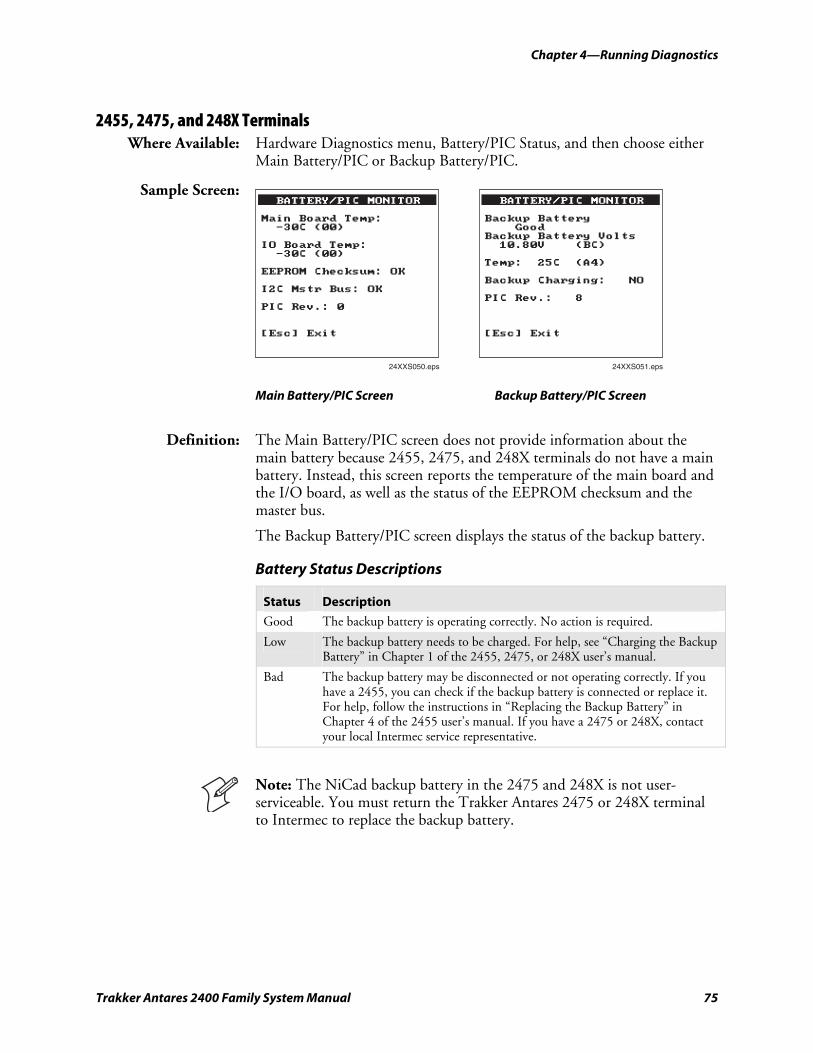
nugget 39 AGaramond Chapter 4—Running Diagnostics
Trakker Antares 2400 Family System Manual 75
2455, 2475, and 248X Terminals Where Available: Hardware Diagnostics menu, Battery/PIC Status, and then choose either
Main Battery/PIC or Backup Battery/PIC.
Sample Screen:
24XXS050.eps
BATTERY/PIC MONITOR
Main Board Temp:-30C (00)
IO Board Temp:-30C (00)
EEPROM Checksum: OK
I2C Mstr Bus: OK
PIC Rev.: 0
[Esc] Exit
24XXS051.eps
BATTERY/PIC MONITOR
Backup BatteryGood
Backup Battery Volts10.80V (BC)
Temp: 25C (A4)
Backup Charging: NO
PIC Rev.: 8
[Esc] Exit
Main Battery/PIC Screen Backup Battery/PIC Screen
Definition: The Main Battery/PIC screen does not provide information about the main battery because 2455, 2475, and 248X terminals do not have a main battery. Instead, this screen reports the temperature of the main board and the I/O board, as well as the status of the EEPROM checksum and the master bus.
The Backup Battery/PIC screen displays the status of the backup battery.
Battery Status Descriptions
Status Description
Good The backup battery is operating correctly. No action is required.
Low The backup battery needs to be charged. For help, see “Charging the Backup Battery” in Chapter 1 of the 2455, 2475, or 248X user’s manual.
Bad The backup battery may be disconnected or not operating correctly. If you have a 2455, you can check if the backup battery is connected or replace it. For help, follow the instructions in “Replacing the Backup Battery” in Chapter 4 of the 2455 user’s manual. If you have a 2475 or 248X, contact your local Intermec service representative.
Note: The NiCad backup battery in the 2475 and 248X is not user-serviceable. You must return the Trakker Antares 2475 or 248X terminal to Intermec to replace the backup battery.
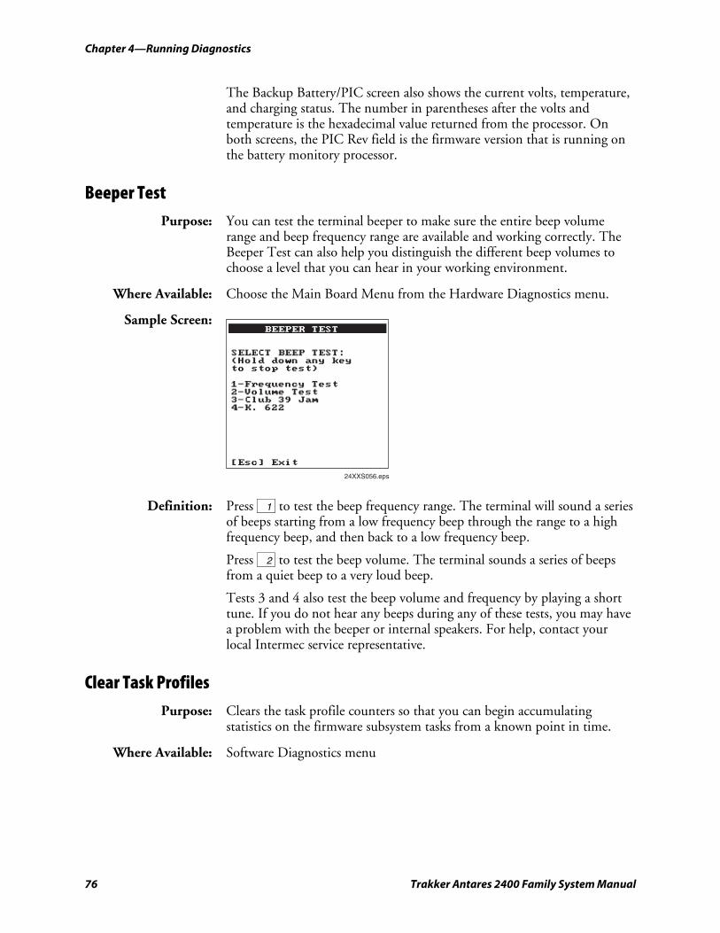
Chapter 4—Running Diagnostics nugget 39 AGaramond
76 Trakker Antares 2400 Family System Manual
The Backup Battery/PIC screen also shows the current volts, temperature, and charging status. The number in parentheses after the volts and temperature is the hexadecimal value returned from the processor. On both screens, the PIC Rev field is the firmware version that is running on the battery monitory processor.
Beeper Test Purpose: You can test the terminal beeper to make sure the entire beep volume
range and beep frequency range are available and working correctly. The Beeper Test can also help you distinguish the different beep volumes to choose a level that you can hear in your working environment.
Where Available: Choose the Main Board Menu from the Hardware Diagnostics menu.
Sample Screen:
24XXS056.eps
BEEPER TEST
SELECT BEEP TEST:(Hold down any keyto stop test)
1-Frequency Test2-Volume Test3-Club 39 Jam4-K. 622
[Esc] Exit
Definition: Press 1 to test the beep frequency range. The terminal will sound a series of beeps starting from a low frequency beep through the range to a high frequency beep, and then back to a low frequency beep.
Press 2 to test the beep volume. The terminal sounds a series of beeps from a quiet beep to a very loud beep.
Tests 3 and 4 also test the beep volume and frequency by playing a short tune. If you do not hear any beeps during any of these tests, you may have a problem with the beeper or internal speakers. For help, contact your local Intermec service representative.
Clear Task Profiles Purpose: Clears the task profile counters so that you can begin accumulating
statistics on the firmware subsystem tasks from a known point in time.
Where Available: Software Diagnostics menu
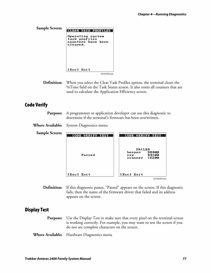
nugget 39 AGaramond Chapter 4—Running Diagnostics
Trakker Antares 2400 Family System Manual 77
Sample Screen: CLEAR TASK PROFILESHardware ConfigOperating systemtask profilescounters have beencleared.
[Esc] Exit
24XXS058.eps
Definition: When you select the Clear Task Profiles option, the terminal clears the %Time field on the Task Status screen. It also resets all counters that are used to calculate the Application Efficiency screen.
Code Verify Purpose: A programmer or application developer can use this diagnostic to
determine if the terminal’s firmware has been overwritten.
Where Available: System Diagnostics menu
Sample Screen: CODE VERIFY TEST
FAILEDbeeper DB400csp D4100scanner CE200
[Esc] Exit
24XXS059.eps
CODE VERIFY TEST
Passed
[Esc] Exit
Definition: If this diagnostic passes, “Passed” appears on the screen. If this diagnostic fails, then the name of the firmware driver that failed and its address appears on the screen.
Display Test Purpose: Use the Display Test to make sure that every pixel on the terminal screen
is working correctly. For example, you may want to test the screen if you do not see complete characters on the screen.
Where Available: Hardware Diagnostics menu
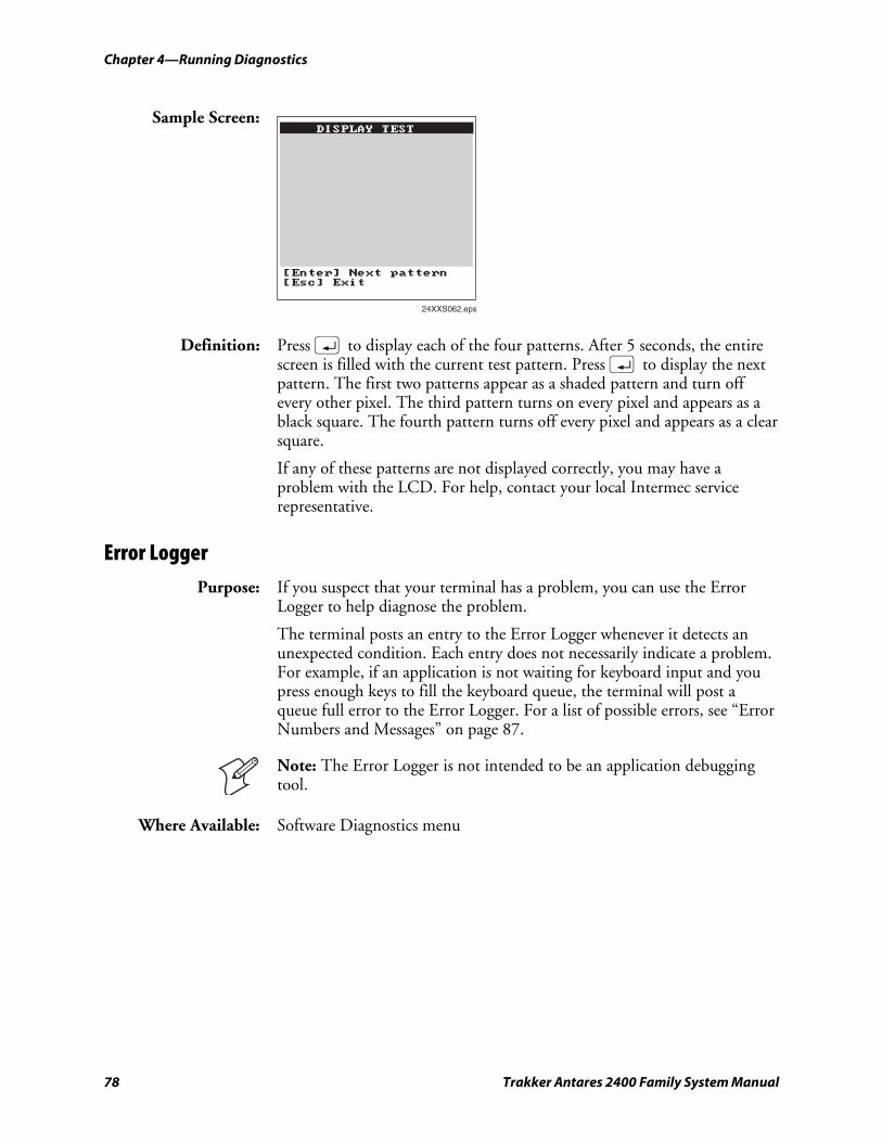
Chapter 4—Running Diagnostics nugget 39 AGaramond
78 Trakker Antares 2400 Family System Manual
Sample Screen:
24XXS062.eps
DISPLAY TEST
[Enter] Next pattern[Esc] Exit
Definition: Press ; to display each of the four patterns. After 5 seconds, the entire screen is filled with the current test pattern. Press ; to display the next pattern. The first two patterns appear as a shaded pattern and turn off every other pixel. The third pattern turns on every pixel and appears as a black square. The fourth pattern turns off every pixel and appears as a clear square.
If any of these patterns are not displayed correctly, you may have a problem with the LCD. For help, contact your local Intermec service representative.
Error Logger Purpose: If you suspect that your terminal has a problem, you can use the Error
Logger to help diagnose the problem.
The terminal posts an entry to the Error Logger whenever it detects an unexpected condition. Each entry does not necessarily indicate a problem. For example, if an application is not waiting for keyboard input and you press enough keys to fill the keyboard queue, the terminal will post a queue full error to the Error Logger. For a list of possible errors, see “Error Numbers and Messages” on page 87.
Note: The Error Logger is not intended to be an application debugging tool.
Where Available: Software Diagnostics menu
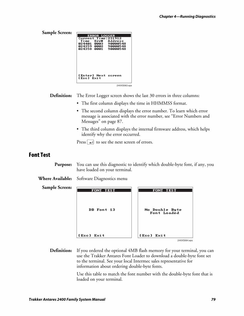
nugget 39 AGaramond Chapter 4—Running Diagnostics
Trakker Antares 2400 Family System Manual 79
Sample Screen:
24XXS063.eps
ERROR LOGGERCurrent Time:231912Time Err# Address024401 0003 90000548024359 0002 90000548024358 0001 90000548
[Enter] Next screen[Esc] Exit
Definition: The Error Logger screen shows the last 30 errors in three columns:
• The first column displays the time in HHMMSS format.
• The second column displays the error number. To learn which error message is associated with the error number, see “Error Numbers and Messages” on page 87.
• The third column displays the internal firmware address, which helps identify why the error occurred.
Press ; to see the next screen of errors.
Font Test Purpose: You can use this diagnostic to identify which double-byte font, if any, you
have loaded on your terminal.
Where Available: Software Diagnostics menu
Sample Screen: FONT TEST
No Double ByteFont Loaded
[Esc] Exit
24XXS064.eps
FONT TEST
DB Font 13
[Esc] Exit
Definition: If you ordered the optional 4MB flash memory for your terminal, you can use the Trakker Antares Font Loader to download a double-byte font set to the terminal. See your local Intermec sales representative for information about ordering double-byte fonts.
Use this table to match the font number with the double-byte font that is loaded on your terminal.
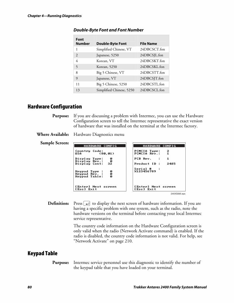
Chapter 4—Running Diagnostics nugget 39 AGaramond
80 Trakker Antares 2400 Family System Manual
Double-Byte Font and Font Number
Font Number
Double-Byte Font
File Name
1 Simplified Chinese, VT 24DBCSCT.fon
2 Japanese, 5250 24DBCSJL.fon
4 Korean, VT 24DBCSKT.fon
5 Korean, 5250 24DBCSKL.fon
8 Big 5 Chinese, VT 24DBCSTT.fon
9 Japanese, VT 24DBCSJT.fon
11 Big 5 Chinese, 5250 24DBCSTL.fon
13 Simplified Chinese, 5250 24DBCSCL.fon
Hardware Configuration Purpose: If you are discussing a problem with Intermec, you can use the Hardware
Configuration screen to tell the Intermec representative the exact version of hardware that was installed on the terminal at the Intermec factory.
Where Available: Hardware Diagnostics menu
Sample Screen:
24XXS065.eps
HARDWARE CONFIG
Country Code:USA (80,01)
Display Type: 0Display Rev.: 0Display Cont: 32
Keypad Type : 0Keypad Rev. : 0Keypad Table: 0
[Enter] Next screen[Esc] Exit
HARDWARE CONFIG
PCMCIA Type: 2PCMCIA Rev.: 1
PCB Rev. : 1
Product ID : 2485
Serial # :X123456789
[Enter] Next screen[Esc] Exit
Definition: Press ; to display the next screen of hardware information. If you are having a specific problem with one system, such as the radio, note the hardware versions on the terminal before contacting your local Intermec service representative.
The country code information on the Hardware Configuration screen is only valid when the radio (Network Activate command) is enabled. If the radio is disabled, the country code information is not valid. For help, see “Network Activate” on page 210.
Keypad Table Purpose: Intermec service personnel use this diagnostic to identify the number of
the keypad table that you have loaded on your terminal.
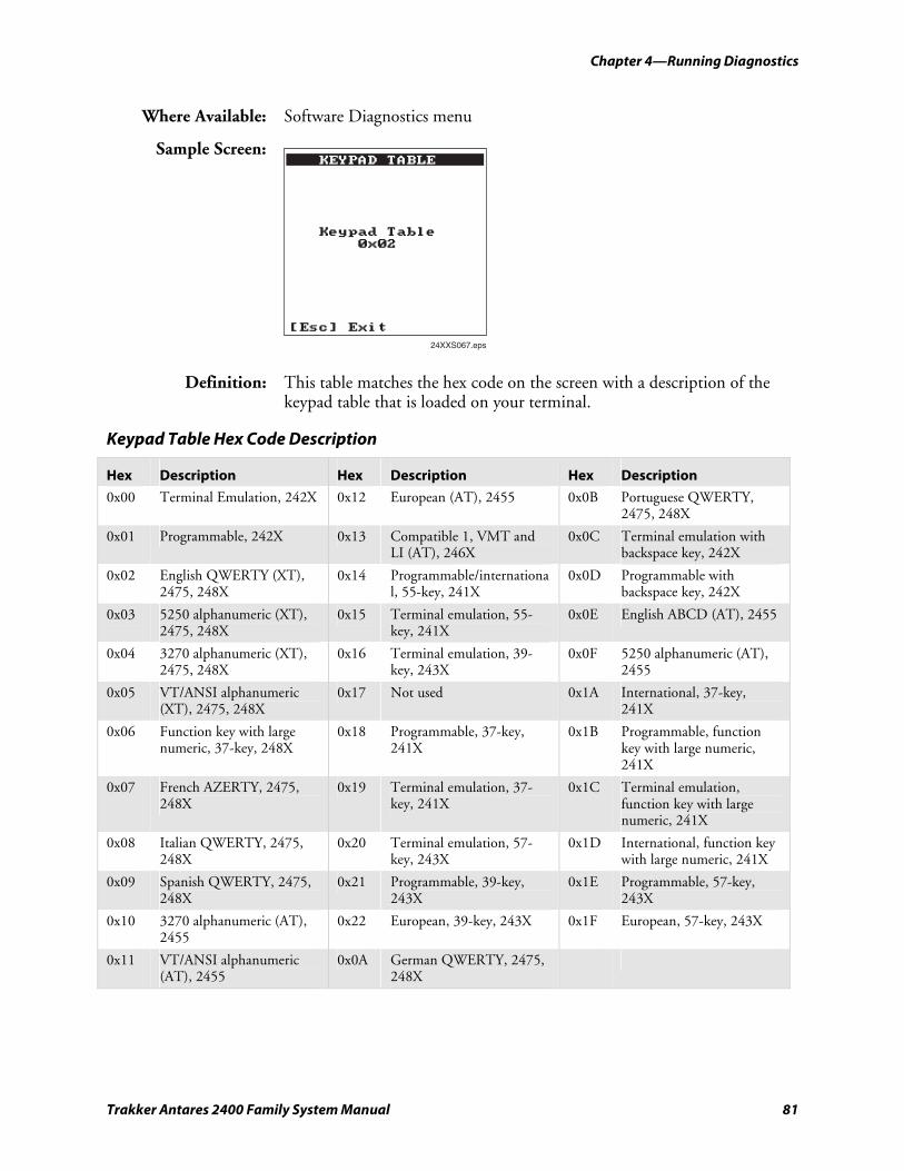
nugget 39 AGaramond Chapter 4—Running Diagnostics
Trakker Antares 2400 Family System Manual 81
Where Available: Software Diagnostics menu
Sample Screen: KEYPAD TABLE
Keypad Table0x02
[Esc] Exit
24XXS067.eps
Definition: This table matches the hex code on the screen with a description of the keypad table that is loaded on your terminal.
Keypad Table Hex Code Description
Hex Description Hex Description Hex Description
0x00 Terminal Emulation, 242X 0x12 European (AT), 2455 0x0B Portuguese QWERTY, 2475, 248X
0x01 Programmable, 242X 0x13 Compatible 1, VMT and LI (AT), 246X
0x0C Terminal emulation with backspace key, 242X
0x02 English QWERTY (XT), 2475, 248X
0x14 Programmable/international, 55-key, 241X
0x0D Programmable with backspace key, 242X
0x03 5250 alphanumeric (XT), 2475, 248X
0x15 Terminal emulation, 55-key, 241X
0x0E English ABCD (AT), 2455
0x04 3270 alphanumeric (XT), 2475, 248X
0x16 Terminal emulation, 39-key, 243X
0x0F 5250 alphanumeric (AT), 2455
0x05 VT/ANSI alphanumeric (XT), 2475, 248X
0x17 Not used 0x1A International, 37-key, 241X
0x06 Function key with large numeric, 37-key, 248X
0x18 Programmable, 37-key, 241X
0x1B Programmable, function key with large numeric, 241X
0x07 French AZERTY, 2475, 248X
0x19 Terminal emulation, 37-key, 241X
0x1C Terminal emulation, function key with large numeric, 241X
0x08 Italian QWERTY, 2475, 248X
0x20 Terminal emulation, 57-key, 243X
0x1D International, function key with large numeric, 241X
0x09 Spanish QWERTY, 2475, 248X
0x21 Programmable, 39-key, 243X
0x1E Programmable, 57-key, 243X
0x10 3270 alphanumeric (AT), 2455
0x22 European, 39-key, 243X 0x1F European, 57-key, 243X
0x11 VT/ANSI alphanumeric (AT), 2455
0x0A German QWERTY, 2475, 248X
Chapter 4—Running Diagnostics nugget 39 AGaramond
82 Trakker Antares 2400 Family System Manual
Keypad Test Purpose: An application programmer can use the Keypad Test screen to quickly find
the hexadecimal key code value, the decimal key code value, and the scan code for any key on the keypad. You can also use the test to make sure the keypad is operating correctly.
Where Available: Hardware Diagnostics menu
Sample Screen:
24XXS068.eps
KEYPAD TEST
Key Hex Dec Scan'a' 61 97 1E'b' 62 98 30'c' 63 99 2E'd' 64 100 20'e' 65 101 12'f' 66 102 21'g' 67 103 22'h' 68 104 23'i' 69 105 17'j' 6A 106 24'k' 6B 107 25'l' 6C 108 26'm' 6D 109 32
[Esc] Exit
Definition: Press any key or key combination on the keypad to display the hexadecimal, decimal, and scan code value of the key. When you press d, the terminal pauses for a few seconds to display the values before you exit the screen. For a complete list of key codes, see the “Trakker Antares Terminal Font Set” on page 290 or refer to the Trakker Antares Application Development Tools System Manual (P/N 064433).
Malloc Application Information Purpose: A programmer or application developer can use the Malloc Application
Information screen to see how memory is allocated and used by the current application.
Where Available: Choose the Malloc Info Menu from the System Diagnostics menu.
Sample Screen:
24XXS070.eps
APPLICATION
Total Free:0000064656
Largest Free:0000064656
Fragments:00001
Allocated Blocks:00001
OK
Definition: The screen displays the memory allocation used by the application. You can view the total free memory, largest block of free memory, number of
nugget 39 AGaramond Chapter 4—Running Diagnostics
Trakker Antares 2400 Family System Manual 83
memory fragments, and total number of allocated blocks of memory. You can use this diagnostic screen to troubleshoot a memory leak where the application is mallocing memory, but not freeing memory.
Malloc Firmware Information Purpose: A programmer or application developer can use the Malloc Firmware
Information screen to see how memory is allocated and used in the terminal firmware. The firmware includes the operating environment, firmware, drivers, and TRAKKER Antares 2400 Menu System.
Where Available: Choose the Malloc Info Menu from the System Diagnostics menu.
Sample Screen:
24XXS071.eps
FIRMWARE
Total Free:0000007040
Largest Free:0000006768
Fragments:00002
Allocated Blocks:00015
OK
Definition: The screen displays the memory allocation for the terminal firmware. You can view the total free memory, the largest block of free memory, the number of memory fragments, and the total number of allocated blocks of memory.
Radio Test Purpose: Use the Radio Test screen to verify that you have a working radio. This
diagnostic only applies to RF terminals.
Where Available: Hardware Diagnostics menu
Sample Screen:
24XXS073.eps
RADIO TEST
TESTING
Test: PASSED
[Esc] Exit
Chapter 4—Running Diagnostics nugget 39 AGaramond
84 Trakker Antares 2400 Family System Manual
Definition: Before you start the test, make sure the radio (Network Activate command) is enabled. If the radio is disabled, the test results on the Radio Test screen are not valid. For help, see “Network Activate” on page 210.
Press ; to start the radio test. The results of the test appear on the screen once the test is complete. If SUCCESS or PASSED appear, the radio is working correctly. If FAILED appears, note the error number. You may have a problem with the radio inside the RF terminal. For help, contact your local Intermec service representative.
If the Radio Test fails, stop using the terminal. Contact your local Intermec service representative.
Attention: Si le test Radio échoue, veuillez ne plus utiliser le terminal. Contactez le représentant du service clientèle Intermec de votre région.
Scanner Test Purpose: Use the Scanner Test to make sure the integrated laser scanner and scan
button or the tethered laser scanner and scanner trigger are operating correctly.
Where Available: Hardware Diagnostics menu
Sample Screen:
24XXS074.eps
SCANNER TEST
Press ENTER to turnthe laser on for 3seconds.
Or, scan a label totest the laser.
[Enter] Execute test[Esc] Exit
Definition: To start the test, press ;. If the laser scanner turns on, the scanner is working correctly. If the laser scanner does not turn on, you may have a problem with the scanner. If you are using a tethered scanner, make sure you are using one that is supported on the terminal.
Note: If you are using a 241X with an integrated linear imager, it takes about 2 seconds for the laser to turn on after you press \. If you are using a 241X with an integrated PDF417 scanner, the laser briefly flashes and then turns on about 2 seconds after you press \.
nugget 39 AGaramond Chapter 4—Running Diagnostics
Trakker Antares 2400 Family System Manual 85
If the laser scanner did turn on in the first test, try scanning a bar code label. If the laser scanner turns on, the scan button or scanner trigger is working correctly. If the laser scanner does not turn on, you may have a problem with the scan button or scanner trigger. For help with scanner problems, contact your local Intermec service representative.
Serial Port Test Purpose: Use the Serial Port Test screen to test or troubleshoot serial
communications between the terminal and the host computer or serial device. To run this diagnostic test, you must connect the terminal to a host or serial loopback connector.
Where Available: System Diagnostics menu
Sample Screen: SERIAL PORT TEST
Select Com. Port:1,4, Esc : 1
F1:Port Select :1F2:Keypad Echo : ONF3:Scanner Echo: ONF4:Continous TX: OFF
Input:Echo:
[Esc] Exit
24XXS076.eps
Definition: Press 1 to test the RS-232 serial communications port. The screen displays the function key options you can use in this diagnostic screen.
Serial Port Test Function Key Options
Function Key Description
F1 Selects the serial port.
F2 Toggles the keypad echo on and off. If you turn the keypad echo on, characters you type on the keypad are displayed on the bottom line of the screen and transmitted to the host.
F3 Toggles the scanner echo on and off. If you turn the scanner echo on, the bar code label you scan is displayed on the bottom line of the screen and transmitted to the host.
F4 Toggles the Continuous Transmit mode on and off. If you turn continuous transmit on, the terminal continuously sends out a string of characters.
Esc Exits the Serial Port Test diagnostic screen.
On the host, you use an RS-232 serial communications package to receive data from the terminal. To test serial communications, enter or scan data on the terminal. If the terminal is communicating with the host, you will see the data. If there is a problem, check the serial port parameters and
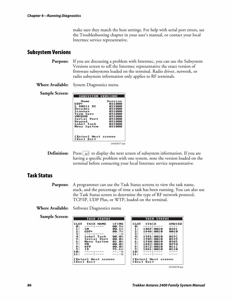
Chapter 4—Running Diagnostics nugget 39 AGaramond
86 Trakker Antares 2400 Family System Manual
make sure they match the host settings. For help with serial port errors, see the Troubleshooting chapter in your user’s manual, or contact your local Intermec service representative.
Subsystem Versions Purpose: If you are discussing a problem with Intermec, you can use the Subsystem
Versions screen to tell the Intermec representative the exact version of firmware subsystems loaded on the terminal. Radio driver, network, or radio subsystem information only applies to RF terminals.
Where Available: System Diagnostics menu
Sample Screen:
24XXS077.eps
SUBSYSTEM VERSIONS
Name VersionUDP+ 031000L 80211 DS 031000Decodes 031000Scanner 031000Term Serv 031000XMODEM 031000Serial Port 031000Keypad 031000Label Task 031000Menu System 031000
[Enter] Next screen[Esc] Exit
Definition: Press ; to display the next screen of subsystem information. If you are having a specific problem with one system, note the version loaded on the terminal before contacting your local Intermec service representative.
Task Status Purpose: A programmer can use the Task Status screens to view the task name,
stack, and the percentage of time a task has been running. You can also use the Task Status screen to determine the type of RF network protocol, TCP/IP, UDP Plus, or WTP, loaded on the terminal.
Where Available: Software Diagnostics menu
Sample Screen: TASK STATUS
SLOT TASK NAME %TIME0: ----:---- 00.5%1: SM 00.1%2: UDP+ 00.7%3: ----:---- --.-%4: Label Task 00.0%5: Serial Port 00.0%6: Menu System 02.0%7: PM 00.0%8: APP 00.0%9: ID 95.6%10: ----:---- --.-%11: ----:---- --.-%
[Enter] Next screen[Esc] Exit
24XXS078.eps
TASK STATUS
SLOT STACK UNUSED0: ----:---- ----1: 1B8F:0010 03812: 1A48:0010 00103: ----:---- ----4: 19F6:0010 029C5: 19B5:0010 03396: 1944:0010 03A57: 18E3:0010 03948: 18C2:0010 011C9: 18A1:0010 011010: ----:---- ----11: ----:---- ----
[Enter] Next screen[Esc] Exit
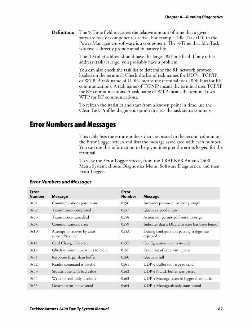
nugget 39 AGaramond Chapter 4—Running Diagnostics
Trakker Antares 2400 Family System Manual 87
Definition: The %Time field measures the relative amount of time that a given software task or component is active. For example, Idle Task (ID) in the Power Management software is a component. The %Time that Idle Task is active is directly proportional to battery life.
The ID (idle) address should have the largest %Time field. If any other address (task) is large, you probably have a problem.
You can also check the task list to determine the RF network protocol loaded on the terminal. Check the list of task names for UDP+, TCP/IP, or WTP. A task name of UDP+ means the terminal uses UDP Plus for RF communications. A task name of TCP/IP means the terminal uses TCP/IP for RF communications. A task name of WTP means the terminal uses WTP for RF communications.
To refresh the statistics and start from a known point in time, use the Clear Task Profiles diagnostic option to clear the task status counters.
Error Numbers and Messages This table lists the error numbers that are posted to the second column on the Error Logger screen and lists the message associated with each number. You can use this information to help you interpret the errors logged for the terminal.
To view the Error Logger screen, from the TRAKKER Antares 2400 Menu System, choose Diagnostics Menu, Software Diagnostics, and then Error Logger.
Error Numbers and Messages
Error Number
Message
Error Number
Message
0x01 Communications port in use 0x56 Incorrect parameter or string length
0x02 Transmission completed 0x57 Queue or pool empty
0x03 Transmission cancelled 0x58 Action not permitted from this origin
0x04 Communications error 0x59 Indicates that a DLE character has been found
0x10 Attempt to recover by auto suspend/resume
0x5A During configuration parsing, a digit was expected
0x11 Card Change Detected 0x5B Configuration item is invalid
0x12 Glitch in communications to radio 0x5F Event out of sync with queue
0x51 Response larger than buffer 0x60 Queue is full
0x52 Reader command is invalid 0x61 UDP+: Buffer too large to send
0x53 Set attribute with bad value 0x62 UDP+: NULL buffer was passed
0x54 Write to read-only attribute 0x63 UDP+: Message received bigger than buffer
0x55 General error not covered 0x64 UDP+: Message already transmitted
Chapter 4—Running Diagnostics nugget 39 AGaramond
88 Trakker Antares 2400 Family System Manual
Error Numbers and Messages (continued)
Error Number
Message
Error Number
Message
0x65 UDP+: Invalid parameter block 0x83 Data or ACK receive failed
0x66 Network not active or not configured properly
0x84 File write failed
0x67 NCB pointer is null 0x85 File close failed
0x68 Data pointer is null or data length invalid
0x86 Controller denied request
0x69 Network error 0x87 Network activate off
0x6A Previous application message occupies send buffer
0x90 Card: unknown command to driver
0x6B Network error 0x91 Card: invalid code
0x6C Network error 0x92 Card: process response
0x6D Network error 0x93 Card: offset too big
0x6E Network error 0x94 Card: entry not in hash list
0x6F An attempt was made to establish a new TCP connection
0x95 Card: security ID
0x70 The Ninit usnet call failed 0x110 No TCB slot available
0x71 The Nportinit usnet call failed 0x111 No RAM available for stack
0x72 The Nterm usnet call failed 0x112 Invalid time
0x73 The Portterm usnet call failed 0x113 Invalid slot
0x74 The Nopen usnet call failed 0x114 Invalid delay type
0x75 The Nclose usnet call failed 0x115 Invalid event
0x76 The Nread usnet call failed 0x116 Invalid group event
0x77 The Nwrite usnet call failed 0x117 Invalid resource
0x78 Invalid group event 0x118 Invalid mailbox
0x79 Network PM failed 0x119 Invalid memory release
0x7A Invalid send buffer 0x11A Function timeout expired
0x7B The send buff is not empty 0x11B Periodic event table full
0x7C A failure occurred in UDP timer 0x11C Invalid profile_type code
0x7D Maximum number of bad sequence numbers has occurred. Possible duplicate IP address in network.
0x11D Invalid MMU180 page number
0x7E Could not connect to controller 0x11E Device not open
0x7F DHCP failed to obtain an IP address 0x11F Device not open or not device owner
0x80 File open failed 0x120 Invalid pool ID
0x81 Read or write request failed 0x121 Invalid block size for pool
0x82 The getbuf usnet call failed 0x122 Invalid pool type
nugget 39 AGaramond Chapter 4—Running Diagnostics
Trakker Antares 2400 Family System Manual 89
Error Numbers and Messages (continued)
Error Number
Message
Error Number
Message
0x123 No table space available for message 0x192 Invalid drive letter
0x134 Invalid file descriptor pointer 0x193 Duplicate file name
0x135 Task not suspended 0x194 Invalid file name
0x136 Not owner of stream 0x195 Directory full
0x137 Stream access error 0x196 Disk full
0x138 Color requested > NUMCOLORS 0x197 Invalid file control block
0x139 Missed system time required 0x198 Invalid seek mode
0x13A Mtenv table full 0x199 Different drives
0x13B Acquire/release table full 0x19A End of file
0x13C Too small of memory release to MTmeminit
0x19B Drive table full
0x13D Chkmem detects memory chain corrupt 0x19C File system error
0x13E MBXLIMIT messages in mailbox 0x19D Invalid seek offset mode combination
0x13F Too small of memory passed to MTmeminit
0x1D0 Application load error
0x140 Memory allocation error 0x1D1 Application load error
0x141 Null pointer passed to system call 0x1E0 Application load error
0x142 Error allocating label task resource 0x1E1 Application load error
0x143 Invalid task name string 0x1E2 No second flash chip, used by display
0x150 File transfer user abort 0x1F0 Add Decode - The Decode symbology is already present in the auto-discrimination table.
0x151 File transfer lost connection 0x1E2 No second flash chip, used by display
0x152 File transfer receiver canceled 0x1F1 Drop Decode - The Decode symbology was not found in the auto-discrimination table.
0x153 File transfer transmitter canceled 0x1F2 Intermediate row which was already read
0x154 File transfer bad protocol character 0x1F3 Intermediate row successfully decoded
0x180 File system type errors 0x1F4 Command symbology (Code 39)
0x181 File open error 0x1F5 Code39 half-ASCII
0x182 File write error 0x1F6 Good decode
0x183 File with no extension error 0x1F7 Label has already been read this trigger pull
0x184 Invalid file extension 0x1F8 Votes aren't all in for the label
0x185 Seek not permitted from Append mode 0x1F9 Get config character returned a quoted quote
0x186 Read not permitted in write only file 0x200 Decodes auto-discrimination table full
0x191 Duplicate drive letter 0x201 Decode Data command error: Not enough resources to attempt to decode the counts.
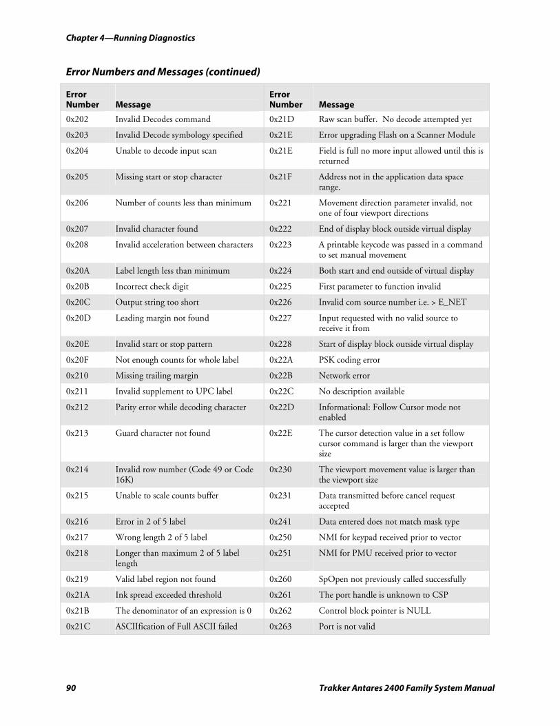
Chapter 4—Running Diagnostics nugget 39 AGaramond
90 Trakker Antares 2400 Family System Manual
Error Numbers and Messages (continued)
Error Number
Message
Error Number
Message
0x202 Invalid Decodes command 0x21D Raw scan buffer. No decode attempted yet
0x203 Invalid Decode symbology specified 0x21E Error upgrading Flash on a Scanner Module
0x204 Unable to decode input scan 0x21E Field is full no more input allowed until this is returned
0x205 Missing start or stop character 0x21F Address not in the application data space range.
0x206 Number of counts less than minimum 0x221 Movement direction parameter invalid, not one of four viewport directions
0x207 Invalid character found 0x222 End of display block outside virtual display
0x208 Invalid acceleration between characters 0x223 A printable keycode was passed in a command to set manual movement
0x20A Label length less than minimum 0x224 Both start and end outside of virtual display
0x20B Incorrect check digit 0x225 First parameter to function invalid
0x20C Output string too short 0x226 Invalid com source number i.e. > E_NET
0x20D Leading margin not found 0x227 Input requested with no valid source to receive it from
0x20E Invalid start or stop pattern 0x228 Start of display block outside virtual display
0x20F Not enough counts for whole label 0x22A PSK coding error
0x210 Missing trailing margin 0x22B Network error
0x211 Invalid supplement to UPC label 0x22C No description available
0x212 Parity error while decoding character 0x22D Informational: Follow Cursor mode not enabled
0x213 Guard character not found 0x22E The cursor detection value in a set follow cursor command is larger than the viewport size
0x214 Invalid row number (Code 49 or Code 16K)
0x230 The viewport movement value is larger than the viewport size
0x215 Unable to scale counts buffer 0x231 Data transmitted before cancel request accepted
0x216 Error in 2 of 5 label 0x241 Data entered does not match mask type
0x217 Wrong length 2 of 5 label 0x250 NMI for keypad received prior to vector
0x218 Longer than maximum 2 of 5 label length
0x251 NMI for PMU received prior to vector
0x219 Valid label region not found 0x260 SpOpen not previously called successfully
0x21A Ink spread exceeded threshold 0x261 The port handle is unknown to CSP
0x21B The denominator of an expression is 0 0x262 Control block pointer is NULL
0x21C ASCIIfication of Full ASCII failed 0x263 Port is not valid
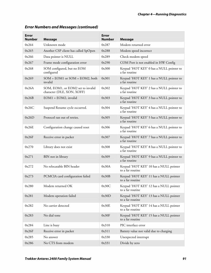
nugget 39 AGaramond Chapter 4—Running Diagnostics
Trakker Antares 2400 Family System Manual 91
Error Numbers and Messages (continued)
Error Number
Message
Error Number
Message
0x264 Unknown mode 0x287 Modem returned error
0x265 Another CSP client has called SpOpen 0x288 Modem speed incorrect
0x266 Data pointer is NULL 0x289 Check modem speed
0x267 Frame mode configuration error 0x290 COM Port is not enabled in HW Config
0x268 SOM configured, but no EOM configured
0x300 Keypad 'HOT KEY' 0 has a NULL pointer to a far routine
0x269 SOM = EOM1 or SOM = EOM2, both invalid
0x301 Keypad 'HOT KEY' 1 has a NULL pointer to a far routine
0x26A SOM, EOM1, or EOM2 set to invalid character (DLE, XON, XOFF)
0x302 Keypad 'HOT KEY' 2 has a NULL pointer to a far routine
0x26B EOM1 = EOM2, invalid 0x303 Keypad 'HOT KEY' 3 has a NULL pointer to a far routine
0x26C Suspend Resume cycle occurred. 0x304 Keypad 'HOT KEY' 4 has a NULL pointer to a far routine
0x26D Protocol ran out of retries. 0x305 Keypad 'HOT KEY' 5 has a NULL pointer to a far routine
0x26E Configuration change caused reset 0x306 Keypad 'HOT KEY' 6 has a NULL pointer to a far routine
0x26F Receive error in packet 0x307 Keypad 'HOT KEY' 7 has a NULL pointer to a far routine
0x270 Library does not exist 0x308 Keypad 'HOT KEY' 8 has a NULL pointer to a far routine
0x271 BIN not in library 0x309 Keypad 'HOT KEY' 9 has a NULL pointer to a far routine
0x272 No relocatable BIN header 0x30A Keypad 'HOT KEY' 10 has a NULL pointer to a far routine
0x273 PCMCIA card configuration failed 0x30B Keypad 'HOT KEY' 11 has a NULL pointer to a far routine
0x280 Modem returned OK 0x30C Keypad 'HOT KEY' 12 has a NULL pointer to a far routine
0x281 Modem operation failed 0x30D Keypad 'HOT KEY' 13 has a NULL pointer to a far routine
0x282 No carrier detected 0x30E Keypad 'HOT KEY' 14 has a NULL pointer to a far routine
0x283 No dial tone 0x30F Keypad 'HOT KEY' 15 has a NULL pointer to a far routine
0x284 Line is busy 0x310 PIC interface error
0x26F Receive error in packet 0x311 Battery value not valid due to charging
0x285 No answer 0x330 Unexpected interrupt
0x286 No CTS from modem 0x331 Divide by zero
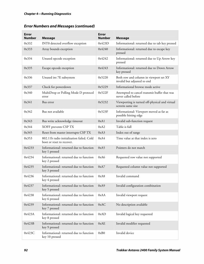
Chapter 4—Running Diagnostics nugget 39 AGaramond
92 Trakker Antares 2400 Family System Manual
Error Numbers and Messages (continued)
Error Number
Message
Error Number
Message
0x332 INT0 detected overflow exception 0x423D Informational: returned due to tab key pressed
0x333 Array bounds exception 0x4240 Informational: returned due to escape key pressed
0x334 Unused opcode exception 0x4242 Informational: returned due to Up Arrow key pressed
0x335 Escape opcode exception 0x4243 Informational: returned due to Down Arrow key pressed
0x336 Unused int 7E subsystem 0x5220 Both row and column in viewport set XY invalid but adjusted to end
0x337 Check for powerdown 0x5229 Informational browse mode active
0x340 MultiDrop or Polling Mode D protocol error
0x522F Attempted to cancel transmit buffer that was never called before
0x341 Bus error 0x5232 Viewporting is turned off-physical and virtual screens same size
0x342 Bus not available 0x523F Informational: Viewport moved as far as possible hitting edge
0x343 Bus write acknowledge timeout 0xA1 Invalid sub-function request
0x344 XOFF prevents CSP TX 0xA2 Table is full
0x345 Reset from master interrupts CSP TX 0xA3 Index out of range
0x353 802.11b radio initialization failed. Cold boot or reset to recover.
0xA4 Time value at that index is zero
0x4233 Informational: returned due to function key 1 pressed
0xA5 Pointers do not match
0x4234 Informational: returned due to function key 2 pressed
0xA6 Requested row value not supported
0x4235 Informational: returned due to function key 3 pressed
0xA7 Requested column value not supported
0x4236 Informational: returned due to function key 4 pressed
0xA8 Invalid command
0x4237 Informational: returned due to function key 5 pressed
0xA9 Invalid configuration combination
0x4238 Informational: returned due to function key 6 pressed
0xAA Invalid viewport request
0x4239 Informational: returned due to function key 7 pressed
0xAC No description available
0x423A Informational: returned due to function key 8 pressed
0xAD Invalid logical key requested
0x423B Informational: returned due to function key 9 pressed
0xAE Invalid modifier requested
0x423C Informational: returned due to function key 10 pressed
0xB0 Invalid device
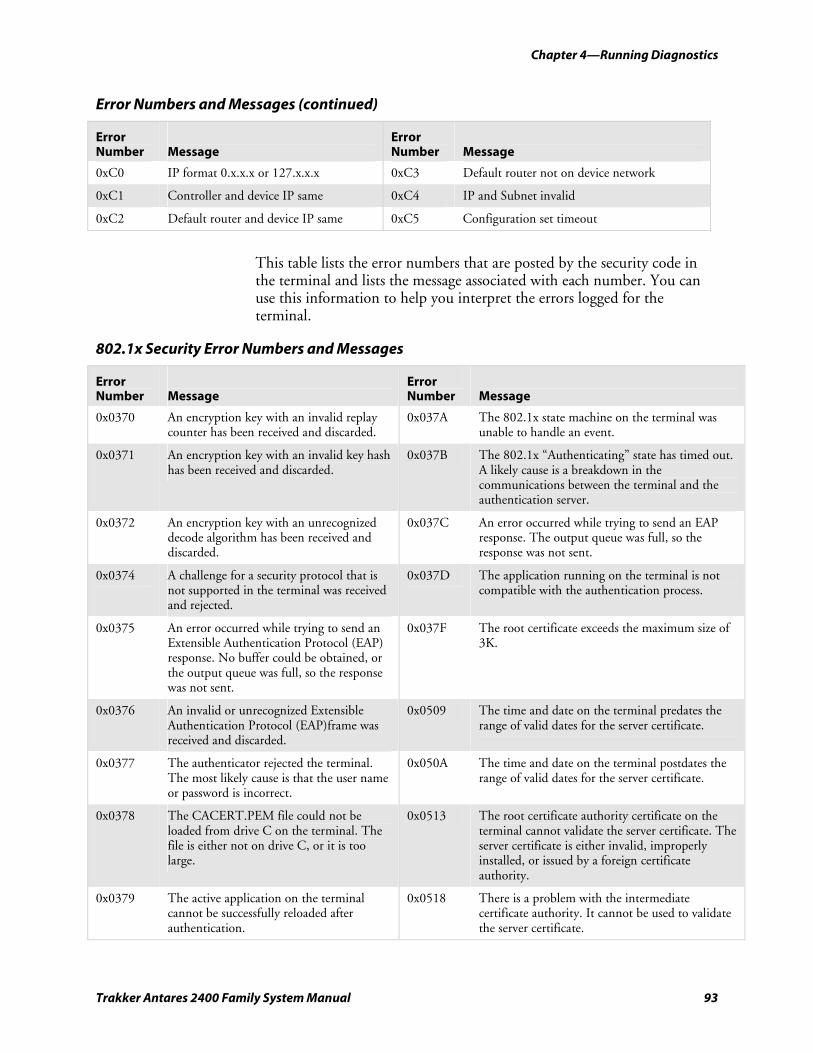
nugget 39 AGaramond Chapter 4—Running Diagnostics
Trakker Antares 2400 Family System Manual 93
Error Numbers and Messages (continued)
Error Number
Message
Error Number
Message
0xC0 IP format 0.x.x.x or 127.x.x.x 0xC3 Default router not on device network
0xC1 Controller and device IP same 0xC4 IP and Subnet invalid
0xC2 Default router and device IP same 0xC5 Configuration set timeout
This table lists the error numbers that are posted by the security code in the terminal and lists the message associated with each number. You can use this information to help you interpret the errors logged for the terminal.
802.1x Security Error Numbers and Messages
Error Number
Message
Error Number
Message
0x0370 An encryption key with an invalid replay counter has been received and discarded.
0x037A The 802.1x state machine on the terminal was unable to handle an event.
0x0371 An encryption key with an invalid key hash has been received and discarded.
0x037B The 802.1x “Authenticating” state has timed out. A likely cause is a breakdown in the communications between the terminal and the authentication server.
0x0372 An encryption key with an unrecognized decode algorithm has been received and discarded.
0x037C An error occurred while trying to send an EAP response. The output queue was full, so the response was not sent.
0x0374 A challenge for a security protocol that is not supported in the terminal was received and rejected.
0x037D The application running on the terminal is not compatible with the authentication process.
0x0375 An error occurred while trying to send an Extensible Authentication Protocol (EAP) response. No buffer could be obtained, or the output queue was full, so the response was not sent.
0x037F The root certificate exceeds the maximum size of 3K.
0x0376 An invalid or unrecognized Extensible Authentication Protocol (EAP)frame was received and discarded.
0x0509 The time and date on the terminal predates the range of valid dates for the server certificate.
0x0377 The authenticator rejected the terminal. The most likely cause is that the user name or password is incorrect.
0x050A The time and date on the terminal postdates the range of valid dates for the server certificate.
0x0378 The CACERT.PEM file could not be loaded from drive C on the terminal. The file is either not on drive C, or it is too large.
0x0513 The root certificate authority certificate on the terminal cannot validate the server certificate. The server certificate is either invalid, improperly installed, or issued by a foreign certificate authority.
0x0379 The active application on the terminal cannot be successfully reloaded after authentication.
0x0518 There is a problem with the intermediate certificate authority. It cannot be used to validate the server certificate.
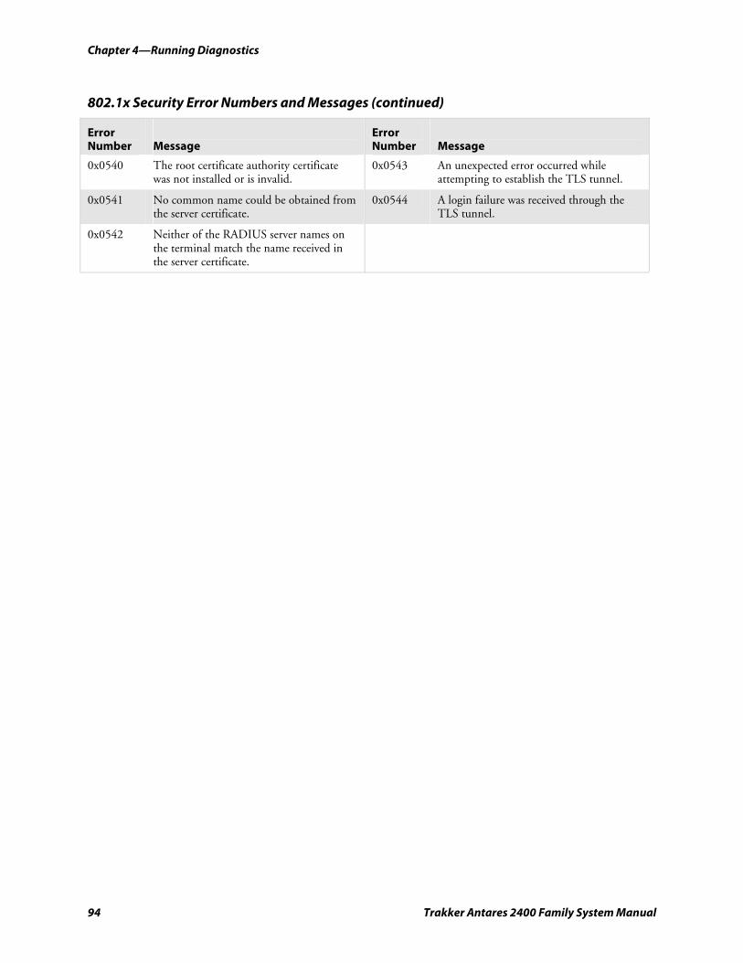
Chapter 4—Running Diagnostics nugget 39 AGaramond
94 Trakker Antares 2400 Family System Manual
802.1x Security Error Numbers and Messages (continued)
Error Number
Message
Error Number
Message
0x0540 The root certificate authority certificate was not installed or is invalid.
0x0543 An unexpected error occurred while attempting to establish the TLS tunnel.
0x0541 No common name could be obtained from the server certificate.
0x0544 A login failure was received through the TLS tunnel.
0x0542 Neither of the RADIUS server names on the terminal match the name received in the server certificate.
Trakker Antares 2400 Family System Manual 95
Reader Command Reference
This chapter describes the reader commands that you can use while operating the terminal. Reader commands, such as Change Configuration, allow you to perform a task on the terminal.
This chapter covers these topics:
• Using reader commands
• Reader commands listed by category
• Using accumulate mode
• Defining the reader commands
5
Chapter 5—Reader Command Reference
96 Trakker Antares 2400 Family System Manual
Using Reader Commands A reader command causes the terminal to perform a task. Some reader commands temporarily override the configuration settings and some actually change the configuration settings. For example, you can reset the terminal to the default configuration or change the configuration.
Note: Not all reader commands are supported in the Reader Command Menu on the terminal.
You can execute reader commands by:
• scanning a command from a Code 39 or Code 93 bar code label.
• pressing keys on the keypad or choosing a command from the TRAKKER Antares 2400 Menu System.
• sending a command from a device on the serial, Ethernet, or RF network.
There are three general types of reader commands:
• Accumulate mode commands
• Operating commands
• File management commands
The accumulate mode commands are described in “Using Accumulate Mode” on page 97. The operating and file management commands are listed alphabetically by command name. For a list of all commands sorted by category, use the table “Reader Commands Listed by Category” on page 97.
Note: The Code 39 bar code labels in this chapter show an asterisk (*) at the beginning and end of the human-readable interpretation to represent the start and stop codes. If you are creating your own Code 39 bar code labels, your bar code printing utility may automatically supply the asterisks as the start/stop code.
Reader Commands Listed by Category This section lists the configuration commands in alphabetical order. Use these lists to find accumulate mode, operating, and file management commands.
Not all reader commands apply to all terminals. Use the following tables to determine which commands are supported on your Trakker Antares® terminal.
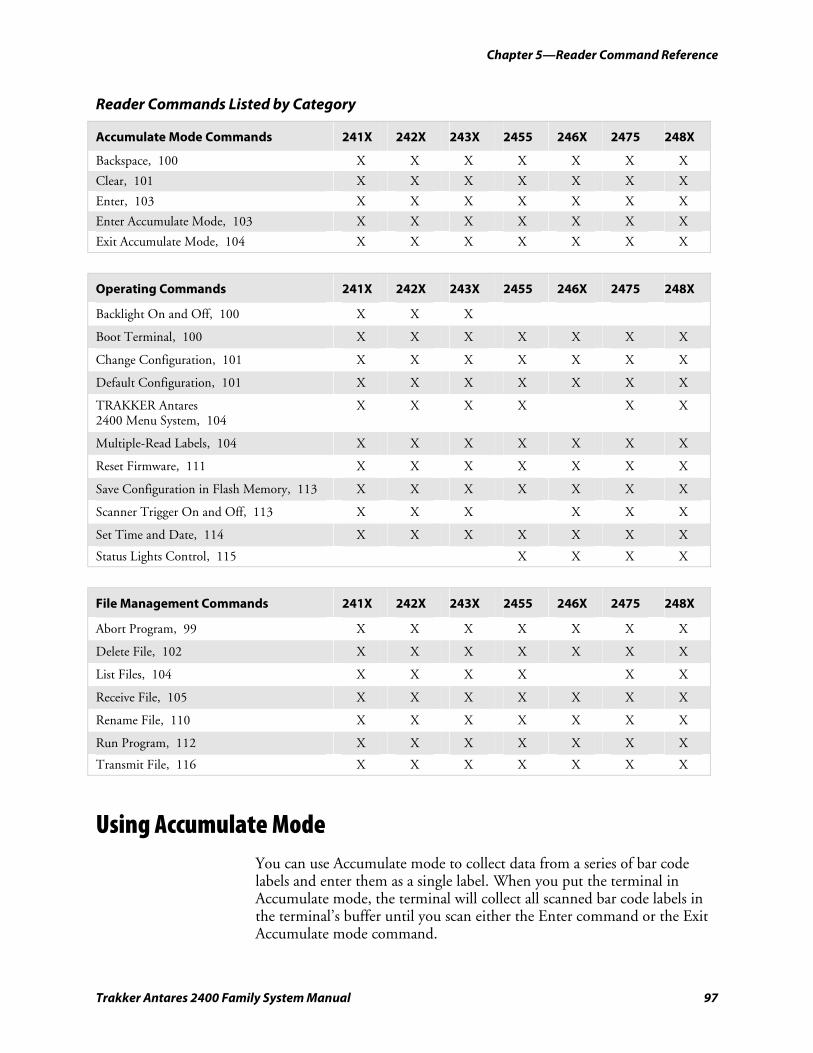
Chapter 5—Reader Command Reference
Trakker Antares 2400 Family System Manual 97
Reader Commands Listed by Category
Accumulate Mode Commands 241X 242X 243X 2455 246X 2475 248X
Backspace, 100 X X X X X X X
Clear, 101 X X X X X X X
Enter, 103 X X X X X X X
Enter Accumulate Mode, 103 X X X X X X X
Exit Accumulate Mode, 104 X X X X X X X
Operating Commands 241X 242X 243X 2455 246X 2475 248X
Backlight On and Off, 100 X X X
Boot Terminal, 100 X X X X X X X
Change Configuration, 101 X X X X X X X
Default Configuration, 101 X X X X X X X
TRAKKER Antares 2400 Menu System, 104
X X X X X X
Multiple-Read Labels, 104 X X X X X X X
Reset Firmware, 111 X X X X X X X
Save Configuration in Flash Memory, 113 X X X X X X X
Scanner Trigger On and Off, 113 X X X X X X
Set Time and Date, 114 X X X X X X X
Status Lights Control, 115 X X X X
File Management Commands 241X 242X 243X 2455 246X 2475 248X
Abort Program, 99 X X X X X X X
Delete File, 102 X X X X X X X
List Files, 104 X X X X X X
Receive File, 105 X X X X X X X
Rename File, 110 X X X X X X X
Run Program, 112 X X X X X X X
Transmit File, 116 X X X X X X X
Using Accumulate Mode You can use Accumulate mode to collect data from a series of bar code labels and enter them as a single label. When you put the terminal in Accumulate mode, the terminal will collect all scanned bar code labels in the terminal’s buffer until you scan either the Enter command or the Exit Accumulate mode command.
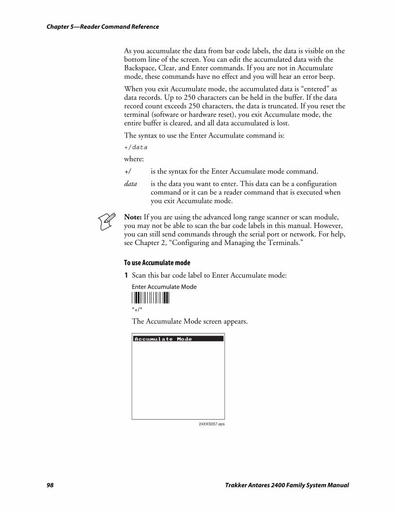
Chapter 5—Reader Command Reference
98 Trakker Antares 2400 Family System Manual
As you accumulate the data from bar code labels, the data is visible on the bottom line of the screen. You can edit the accumulated data with the Backspace, Clear, and Enter commands. If you are not in Accumulate mode, these commands have no effect and you will hear an error beep.
When you exit Accumulate mode, the accumulated data is “entered” as data records. Up to 250 characters can be held in the buffer. If the data record count exceeds 250 characters, the data is truncated. If you reset the terminal (software or hardware reset), you exit Accumulate mode, the entire buffer is cleared, and all data accumulated is lost.
The syntax to use the Enter Accumulate command is:
+/data
where:
+/ is the syntax for the Enter Accumulate mode command.
data is the data you want to enter. This data can be a configuration command or it can be a reader command that is executed when you exit Accumulate mode.
Note: If you are using the advanced long range scanner or scan module, you may not be able to scan the bar code labels in this manual. However, you can still send commands through the serial port or network. For help, see Chapter 2, “Configuring and Managing the Terminals.”
To use Accumulate mode
1 Scan this bar code label to Enter Accumulate mode:
Enter Accumulate Mode
*+/* *+/*
The Accumulate Mode screen appears.
24XXS057.eps
Accumulate Mode
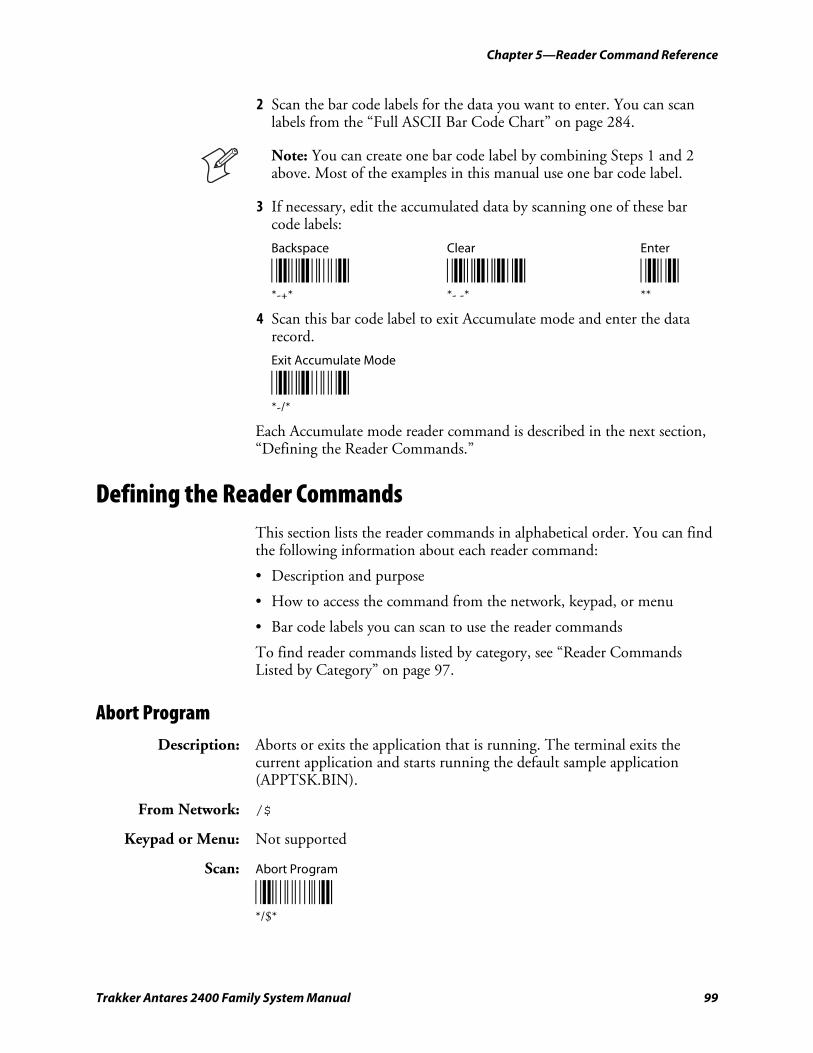
Chapter 5—Reader Command Reference
Trakker Antares 2400 Family System Manual 99
2 Scan the bar code labels for the data you want to enter. You can scan labels from the “Full ASCII Bar Code Chart” on page 284.
Note: You can create one bar code label by combining Steps 1 and 2 above. Most of the examples in this manual use one bar code label.
3 If necessary, edit the accumulated data by scanning one of these bar code labels:
Backspace Clear Enter
*-+* *--* ** *-+* *- -* **
4 Scan this bar code label to exit Accumulate mode and enter the data record.
Exit Accumulate Mode
*-/* *-/*
Each Accumulate mode reader command is described in the next section, “Defining the Reader Commands.”
Defining the Reader Commands This section lists the reader commands in alphabetical order. You can find the following information about each reader command:
• Description and purpose
• How to access the command from the network, keypad, or menu
• Bar code labels you can scan to use the reader commands
To find reader commands listed by category, see “Reader Commands Listed by Category” on page 97.
Abort Program Description: Aborts or exits the application that is running. The terminal exits the
current application and starts running the default sample application (APPTSK.BIN).
From Network: /$
Keypad or Menu: Not supported
Scan: Abort Program
*/$* */$*
Chapter 5—Reader Command Reference
100 Trakker Antares 2400 Family System Manual
Backlight On and Off Description: Turns the backlight on to easily view the terminal screen in dimly lit
environments, or turns the backlight off. If the backlight is on, it stays on for the length of time set in the Display Backlight Timeout command as long as there is no keypad or scanning activity.
From Network: %.1 Backlight On
%.0 Backlight Off
%.2 Toggle Backlight
Keypad or Menu: Press the Backlight key (+ or +) or key sequence to turn the backlight on or off.
Scan: Backlight On Backlight Off
*%.1* *%.0* *%.1* *%.0*
Toggle Backlight
*%.2* *%.2*
Backspace Description: Deletes the last character from the current data record being accumulated.
If there is no data in the buffer, the command has no effect.
From Network: Not supported
Keypad or Menu: Not supported
Scan: Backspace
*-+* *-+*
Boot Terminal Description: Boots the terminal. The terminal runs through power-on self test (POST)
to test each major subsystem. The terminal then uses the configuration currently saved in flash memory to boot, and your application appears on the screen.
Use this command when you upgrade the firmware on the terminal or if your terminal locks up and will not respond.
From Network: -.1
Keypad or Menu: From the Main Menu, choose System Menu and then Upgrade Firmware. Choose OK, choose YES, and then press d. The Boot Menu appears. Press 1 or B to boot the terminal.
Chapter 5—Reader Command Reference
Trakker Antares 2400 Family System Manual 101
Scan: Boot Terminal
*-.1* *-.1*
Change Configuration Description: This command must precede any configuration command. If you
enter a valid string, the terminal configuration is modified and the terminal sounds a high beep. For help with configuration commands, see Chapter 6, “Configuration Command Reference.”
From Network: $+command[command]...[command n]
where command is a configuration command with the value you want to set.
Keypad or Menu: From the Main Menu, choose Configuration Menu.
Example: Change Configuration / Turn Off Beep Volume
*$+BV0* *$+BV0*
The Change Configuration command is followed by the configuration command to turn off the beep volume (BV0).
Clear Description: Deletes the entire data record you are accumulating. If there is no data in
the buffer, the command has no effect.
From Network: Not supported
Keypad or Menu: Not supported
Scan: Clear
*--* *- -*
Default Configuration Description: Sets the current and active terminal configurations to the default
configuration, resets the firmware, boots the terminal, and runs your application. This command does not reset the time and date. The default configuration for the terminal is listed starting on page 272. For help, see “Restoring the Terminal’s Default Configuration” on page 30.
When you use this command, the default configuration is saved in RAM and flash memory. The runtime and boot configuration are changed to the default configuration.
Chapter 5—Reader Command Reference
102 Trakker Antares 2400 Family System Manual
If you restore the default configuration, you must set the primary network communications parameters on the RF terminal to reestablish communications with other devices in the RF network. You may also need to reset the serial port or Ethernet parameters to communicate with other devices in your wired network. For help, see Chapter 2, “Configuring and Managing the Terminals.”
From Network: .+0
Keypad or Menu: From the Main Menu, choose System Menu, and then choose Load Default Values.
Scan: Default Configuration
*.+0* *.+0*
Delete File Description: Deletes a file from a drive on the terminal.
From Network: ..--drive:filename
where:
..–– is the command to delete a file.
drive: indicates the drive where you want to delete a file. You must include the colon (:) after the drive letter.
filename is the file you want to delete.
Note: You cannot use wildcard characters with this reader command. For example, you cannot send the command “..c:*.*” to the terminal.
Keypad or Menu: From the Main Menu, choose System Menu, and then choose File Manager. Choose the drive where you want to delete files.
Note: To use the bar code labels from the “Full ASCII Bar Code Chart,” you may need to configure the terminal to use Code 39 in Full ASCII mode. For help, see “Code 39” on page 146.
Scan: Follow these steps:
1 Scan this bar code label:
Enter Accumulate Mode / Delete File
*+/..--* *+/..--*
Chapter 5—Reader Command Reference
Trakker Antares 2400 Family System Manual 103
2 Scan the bar code labels for the file you want to delete. You can scan labels from the “Full ASCII Bar Code Chart” on page 284. The label must use this format:
drive:filename
3 Scan this bar code label to exit Accumulate mode and delete the file.
Exit Accumulate Mode
*-/* *-/*
Or: You can create your own bar code labels to delete files by creating a bar code in this command format:
..--drive:filename
Example: To delete the file SHIPPING.BIN from drive C, use this command:
..--c:shipping.bin
Enter Description: Enters the current data record and remains in Accumulate mode. If no
data exists, a null string is entered.
Note: The Enter command consists of a Start and Stop character and does not contain any data values. Therefore, if the terminal is configured for a decoded input device, which requires at least one data value in a bar code, it cannot scan the Enter command. For a list of decoded input devices, see your user’s manual or contact your local Intermec sales representative.
From Network: Not supported
Keypad or Menu: Not supported
Scan: Enter
** **
Enter Accumulate Mode Description: Enters Accumulate mode. You can accumulate data from a series of bar
code labels and enter them as a single label.
From Network: Not supported
Keypad or Menu: Not supported
Scan: Enter Accumulate Mode
*+/* *+/*
Chapter 5—Reader Command Reference
104 Trakker Antares 2400 Family System Manual
Exit Accumulate Mode Description: Exits Accumulate mode and transmits the current data record. If no data
has been accumulated, an empty data record is entered.
From Network: Not supported
Keypad or Menu: Not supported
Scan: Exit Accumulate Mode
*-/* *-/*
List Files Description: A List Files reader command is not available in the current release.
However, if you want to see a list of files on the terminal, you can use the TRAKKER Antares 2400 Menu System.
Keypad or Menu: From the Main Menu, choose System Menu, and then choose File Manager. Choose the drive where you want to list the files.
TRAKKER Antares 2400 Menu System Description: Starts the TRAKKER Antares 2400 Menu System.
Note: You can use the Command Processing configuration command to disable the TRAKKER Antares 2400 Menu System reader command. If you disable this reader command, you can no longer access the TRAKKER Antares 2400 Menu System using the keypad. For help, see “Command Processing” on page 158.
From Network: Not supported
Keypad or Menu: ) ; 2 4 8
Scan: TRAKKER Antares 2400 Menu System
*..-.* *..-.*
Multiple-Read Labels Description: A multiple-read label is a Code 39 or Code 93 bar code label that has a
space as the first character after the start code. The terminal stores a multiple-read label in the buffer until you execute a command to transmit the label or scan a regular label.
Chapter 5—Reader Command Reference
Trakker Antares 2400 Family System Manual 105
If you disable multiple-read labels, the terminal processes the bar code label as a regular label and reads and decodes the space as data. A regular bar code label is executed as soon as you scan it.
From Network: Not supported
Keypad or Menu: Not supported
Label Syntax: <Start Code><SP>data<Stop Code>
where <SP> is the ASCII space character and data is the content of the label.
Example: Multiple-Read Bar Code Label
* A* * A*
After you scan a multiple-read bar code label, the accumulated data appears on the bottom line of the terminal screen. You can use the Accumulate mode commands, such as Backspace or Clear, to edit the data.
Receive File There are three ways to receive files on the Trakker Antares terminals:
• Use the serial port to receive files on the terminal
• Use the serial port to receive and convert 7-bit ASCII files to 8-bit binary files on the terminal
• Use network communications to receive files on the RF or Ethernet terminal
For help connecting the terminal to a host computer or the DCS 300, see your user’s manual.
Receive File Through the Serial Port Description: Receives a file from the host computer through the serial port and saves it
on the terminal.
On the host, you must transmit the file using a serial communications package (i.e., Windows 3.1 Terminal, Win95 HyperTerminal, Crosstalk, or ProComm) that supports one of these protocols:
• XMODEM
• XMODEM-1K
• YMODEM
XMODEM-1K is a version of XMODEM that supports 1024-byte blocks and the standard 128-byte XMODEM data blocks, which increases the throughput. YMODEM has the additional ability to transfer a file name with the file’s data, and it preserves the length of the file without padding. With YMODEM, you can also receive a batch of files on the terminal.
Chapter 5—Reader Command Reference
106 Trakker Antares 2400 Family System Manual
Note: Trakker Antares filenames are up to eight characters with a three-character extension. Files you transfer from the host must use the Trakker Antares naming conventions.
From Network: .%Xn,drive:filename Receives a file using XMODEM protocol
.%Kn,drive:filename Receives a file using XMODEM-1K protocol
.%Yn,drive:filename Receives a file using YMODEM protocol
Or: .%Yn,drive: Receives a batch of files using YMODEM
where:
.%X is the command to receive a file using XMODEM protocol.
.%K is the command to receive a file using XMODEM-1K protocol.
.%Y is the command to receive a file using YMODEM protocol.
n indicates the terminal’s serial port: 1, 2, or 4.
drive: indicates the drive on the terminal where you want to receive and store the file. You must include the colon (:) after the drive letter.
filename is the file you want to receive and save on the terminal.
Keypad or Menu: Not supported
Note: To scan these bar code labels, you must configure the terminal to use Code 39 in Full ASCII mode. For help, see “Code 39” on page 146.
Scan: Follow these steps:
1 Scan this bar code label:
Enter Accumulate Mode / Receive File
*/K/O./E* *+/.%*
2 Scan the bar code label for the communications protocol you want to use.
XMODEM XMODEM-1K YMODEM
*X* *K* *Y* *X* *K* *Y*
3 Scan the bar code label for the terminal COM port you are using to receive the file. The label also includes the required comma.
COM1 COM2 COM4
*1/L* *2/L* *4/L* *1,* *2,* *4,*
Chapter 5—Reader Command Reference
Trakker Antares 2400 Family System Manual 107
4 Scan the bar code label or labels for the file you want to receive. You can scan labels from the “Full ASCII Bar Code Chart” on page 284. The label must use this format:
drive:filename
5 Scan this bar code label to exit Accumulate mode and receive the file.
Exit Accumulate Mode
*-/* *-/*
Or: You can create your own bar code labels to receive files by creating a bar code in this command format:
.%Xn,drive:filename (for XMODEM)
.%Kn,drive:filename (for XMODEM-1K)
.%Yn,drive:filename (for YMODEM)
Example: To receive the file SHIPPING.BIN on the terminal’s drive C by using the XMODEM protocol through COM1, use this command:
.%X1,c:shipping.bin
Batch Transfer: To transfer a batch of files to the terminal by using the YMODEM protocol, use your serial communications package to start the transfer. You usually select a batch of files using a wild card file specification. The host must send only the filename and extension, not the drive and directory path in the data stream.
Next, use this command to receive the files on the terminal:
.%Yn,drive:
For example, to receive the files through COM1 to drive C on the terminal, use this command:
.%Y1,c:
All files that match the wild card specification are transferred from the host and received to drive C on the terminal. If any file does not transfer, the remainder of the batch transfer is aborted.
Receive and Convert 7-Bit ASCII Files to 8-Bit Binary Files Description: Receives a file from the host computer through the serial port, converts the
file from a 7-bit ASCII hexadecimal file to an 8-bit binary file, and saves the file on the terminal. You must have the terminal connected to the host through a serial port. For help, see your user’s manual.
Terminal applications are 8-bit binary files. Some network protocols like the Intermec Multi-Drop protocol in a CrossBar network use 7-bit ASCII files. When you send 8-bit binary files across a 7-bit system without converting the files, the files are not compatible and will not run on the terminal.
Chapter 5—Reader Command Reference
108 Trakker Antares 2400 Family System Manual
On the host, you use a hexadecimal conversion utility to convert the 8-bit binary file to a 7-bit ASCII hexadecimal file. Intermec has a DOS utility called HEX.EXE to convert files. The source code for HEX.EXE is also available. For help, see your Intermec service representative. Once the file is converted to a 7-bit ASCII hexadecimal file, you use the Receive File command and a host utility to transfer the 7-bit file to the terminal and convert it back to an 8-bit file.
Note: Trakker Antares filenames are up to eight characters with a three-character extension. Files you transfer from the host must use the Trakker Antares naming conventions.
From Network: .%Hn,drive:filename
where:
.%H is the command to receive a file that was converted from 7-bit ASCII hexadecimal and convert it back to an 8-bit binary file. The terminal uses the current serial port configuration (protocol, baud rate, etc.) for the file transfer.
n indicates the terminal’s serial port: 1, 2, or 4.
drive: indicates the drive on the terminal where you want to receive and store the file. You must include the colon (:) after the drive letter.
filename is the file you want to receive and save on the terminal.
Keypad or Menu: Not supported
Note: To scan these bar code labels, you must configure the terminal to use Code 39 in Full ASCII mode. For help, see “Code 39” on page 146.
Scan: Follow these steps:
1 Scan this bar code label:
Enter Accumulate Mode / Receive File
*/K/O./EH* *+/.%H*
2 Scan the bar code label for the terminal COM port you are using to receive the file. The label also includes the required comma.
COM1 COM2 COM4
*1/L* *2/L* *4/L* *1,* *2,* *4,*
3 Scan the bar code label or labels for the file you want to receive. You can scan labels from the “Full ASCII Bar Code Chart” on page 284. The label must use this format:
drive:filename
Chapter 5—Reader Command Reference
Trakker Antares 2400 Family System Manual 109
4 Scan this bar code label to exit Accumulate mode and receive the file.
Exit Accumulate Mode
*-/* *-/*
Or: You can create your own bar code labels to receive files by creating a bar code in this command format:
.%Hn,drive:filename
Example: You want to send an application from the host in your CrossBar network to the terminal. On the host, use HEX.EXE to convert the application from SHIPPING.BIN to SHIPPING.HEX. On the host, use a utility such as InterScan to transmit SHIPPING.HEX through the 9154 or 9161 to the terminal. Enter this command to receive the file SHIPPING.BIN on the terminal’s drive C through COM2:
.%H2,c:shipping.bin
The file SHIPPING.HEX is transferred, converted from 7-bit ASCII hexadecimal to 8-bit binary, and stored as SHIPPING.BIN on the terminal.
Receive File Through Network Communications Description: Receives a file from the DCS 300 or host and saves it on the RF or
Ethernet terminal.
From Network: .%R,fromfilename,drive:tofilename
where:
.%R is the command to receive a file that is transmitted over the RF or Ethernet network to the terminal.
fromfilename is the name of the file you are transmitting from the DCS 300 or host to the terminal. On the DCS 300, the file must be sent from the D:\USERDATA directory. To receive a file from the host, you must identify the path and filename.
Note: Do not enter D:\USERDATA in the fromfilename field.
drive: indicates the drive on the RF or Ethernet terminal where you want to receive and store the file. You must include the colon (:) after the drive letter.
tofilename is the name of the file you want to save on the RF or Ethernet terminal.
Keypad or Menu: Not supported
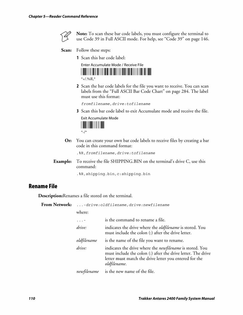
Chapter 5—Reader Command Reference
110 Trakker Antares 2400 Family System Manual
Note: To scan these bar code labels, you must configure the terminal to use Code 39 in Full ASCII mode. For help, see “Code 39” on page 146.
Scan: Follow these steps:
1 Scan this bar code label:
Enter Accumulate Mode / Receive File
*/K/O./ER/L* *+/.%R,*
2 Scan the bar code labels for the file you want to receive. You can scan labels from the “Full ASCII Bar Code Chart” on page 284. The label must use this format:
fromfilename,drive:tofilename
3 Scan this bar code label to exit Accumulate mode and receive the file.
Exit Accumulate Mode
*-/* *-/*
Or: You can create your own bar code labels to receive files by creating a bar code in this command format:
.%R,fromfilename,drive:tofilename
Example: To receive the file SHIPPING.BIN on the terminal’s drive C, use this command:
.%R,shipping.bin,c:shipping.bin
Rename File Description:Renames a file stored on the terminal.
From Network: ...-drive:oldfilename,drive:newfilename
where:
...- is the command to rename a file.
drive: indicates the drive where the oldfilename is stored. You must include the colon (:) after the drive letter.
oldfilename is the name of the file you want to rename.
drive: indicates the drive where the newfilename is stored. You must include the colon (:) after the drive letter. The drive letter must match the drive letter you entered for the oldfilename.
newfilename is the new name of the file.
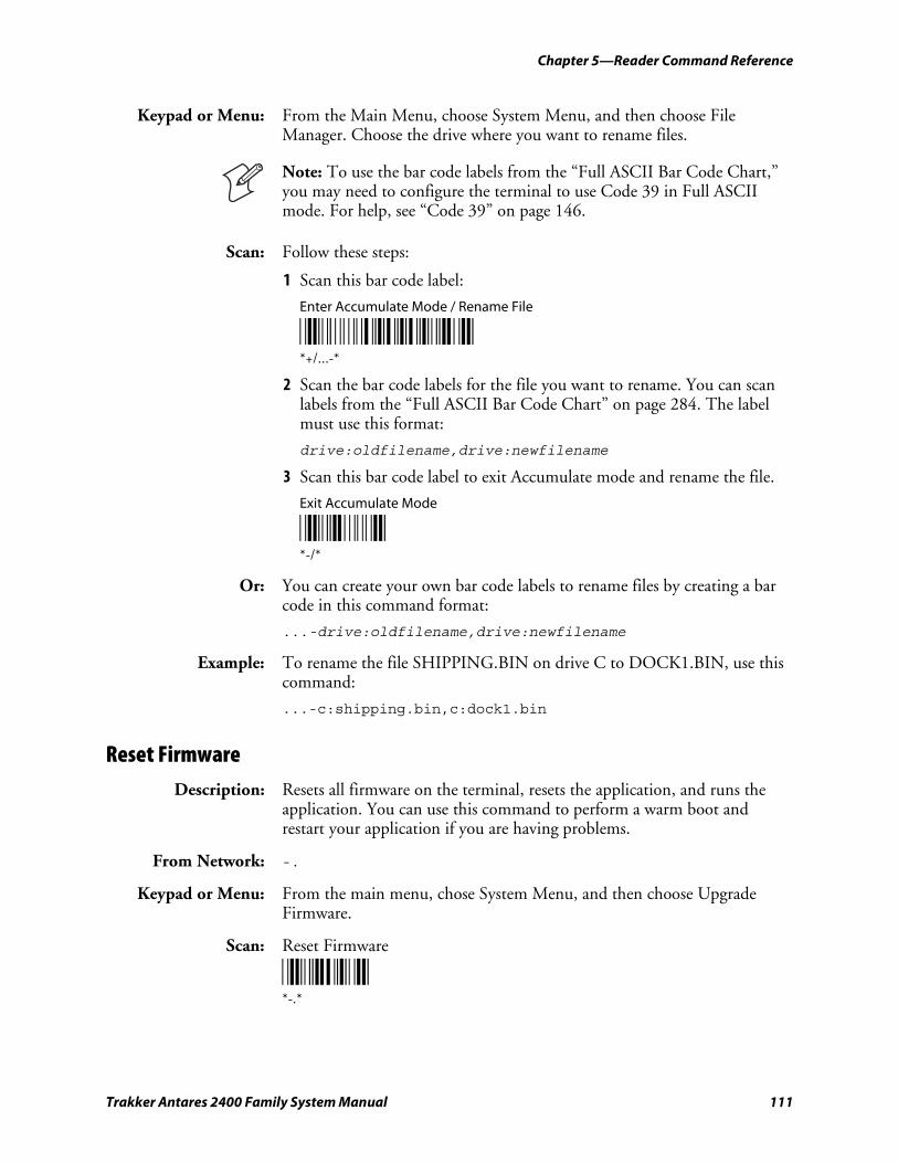
Chapter 5—Reader Command Reference
Trakker Antares 2400 Family System Manual 111
Keypad or Menu: From the Main Menu, choose System Menu, and then choose File Manager. Choose the drive where you want to rename files.
Note: To use the bar code labels from the “Full ASCII Bar Code Chart,” you may need to configure the terminal to use Code 39 in Full ASCII mode. For help, see “Code 39” on page 146.
Scan: Follow these steps:
1 Scan this bar code label:
Enter Accumulate Mode / Rename File
*+/...-* *+/...-*
2 Scan the bar code labels for the file you want to rename. You can scan labels from the “Full ASCII Bar Code Chart” on page 284. The label must use this format:
drive:oldfilename,drive:newfilename
3 Scan this bar code label to exit Accumulate mode and rename the file.
Exit Accumulate Mode
*-/* *-/*
Or: You can create your own bar code labels to rename files by creating a bar code in this command format:
...-drive:oldfilename,drive:newfilename
Example: To rename the file SHIPPING.BIN on drive C to DOCK1.BIN, use this command:
...-c:shipping.bin,c:dock1.bin
Reset Firmware Description: Resets all firmware on the terminal, resets the application, and runs the
application. You can use this command to perform a warm boot and restart your application if you are having problems.
From Network: -.
Keypad or Menu: From the main menu, chose System Menu, and then choose Upgrade Firmware.
Scan: Reset Firmware
*-.* *-.*
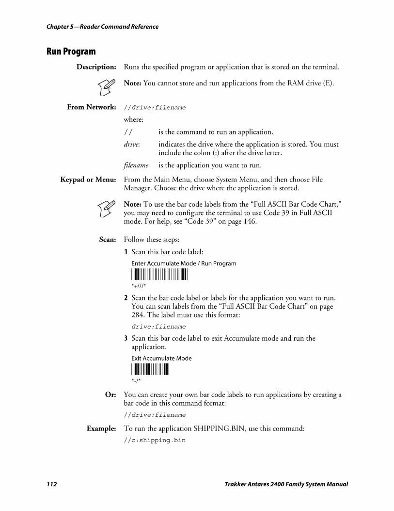
Chapter 5—Reader Command Reference
112 Trakker Antares 2400 Family System Manual
Run Program Description: Runs the specified program or application that is stored on the terminal.
Note: You cannot store and run applications from the RAM drive (E).
From Network: //drive:filename
where:
// is the command to run an application.
drive: indicates the drive where the application is stored. You must include the colon (:) after the drive letter.
filename is the application you want to run.
Keypad or Menu: From the Main Menu, choose System Menu, and then choose File Manager. Choose the drive where the application is stored.
Note: To use the bar code labels from the “Full ASCII Bar Code Chart,” you may need to configure the terminal to use Code 39 in Full ASCII mode. For help, see “Code 39” on page 146.
Scan: Follow these steps:
1 Scan this bar code label:
Enter Accumulate Mode / Run Program
*+///* *+///*
2 Scan the bar code label or labels for the application you want to run. You can scan labels from the “Full ASCII Bar Code Chart” on page 284. The label must use this format:
drive:filename
3 Scan this bar code label to exit Accumulate mode and run the application.
Exit Accumulate Mode
*-/* *-/*
Or: You can create your own bar code labels to run applications by creating a bar code in this command format:
//drive:filename
Example: To run the application SHIPPING.BIN, use this command:
//c:shipping.bin
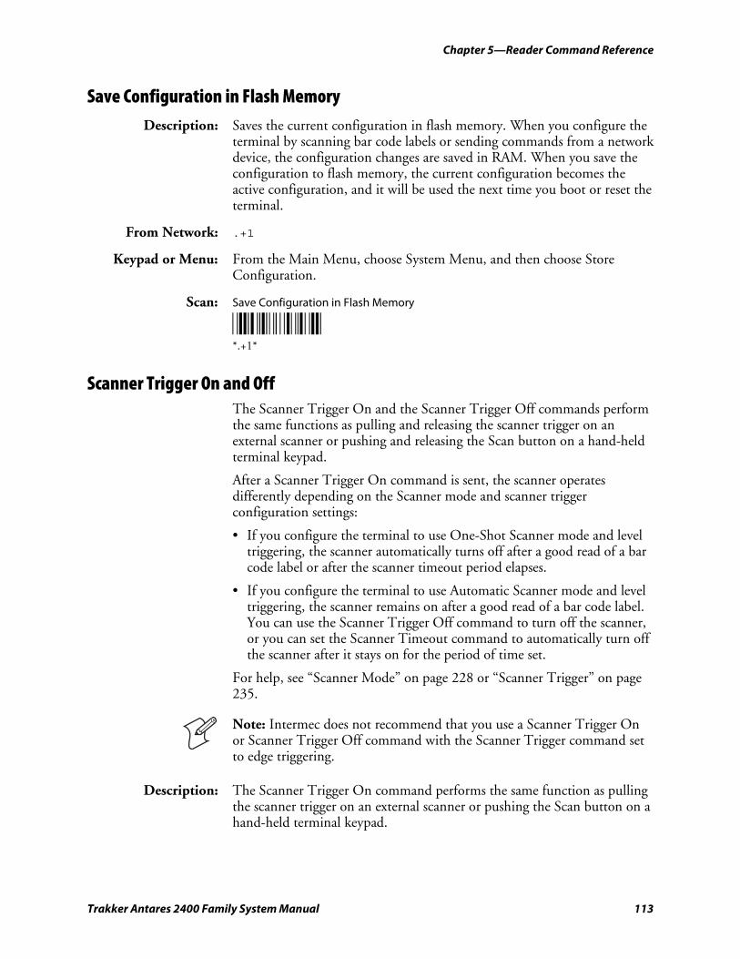
Chapter 5—Reader Command Reference
Trakker Antares 2400 Family System Manual 113
Save Configuration in Flash Memory Description: Saves the current configuration in flash memory. When you configure the
terminal by scanning bar code labels or sending commands from a network device, the configuration changes are saved in RAM. When you save the configuration to flash memory, the current configuration becomes the active configuration, and it will be used the next time you boot or reset the terminal.
From Network: .+1
Keypad or Menu: From the Main Menu, choose System Menu, and then choose Store Configuration.
Scan: Save Configuration in Flash Memory
*.+1* *.+1*
Scanner Trigger On and Off The Scanner Trigger On and the Scanner Trigger Off commands perform the same functions as pulling and releasing the scanner trigger on an external scanner or pushing and releasing the Scan button on a hand-held terminal keypad.
After a Scanner Trigger On command is sent, the scanner operates differently depending on the Scanner mode and scanner trigger configuration settings:
• If you configure the terminal to use One-Shot Scanner mode and level triggering, the scanner automatically turns off after a good read of a bar code label or after the scanner timeout period elapses.
• If you configure the terminal to use Automatic Scanner mode and level triggering, the scanner remains on after a good read of a bar code label. You can use the Scanner Trigger Off command to turn off the scanner, or you can set the Scanner Timeout command to automatically turn off the scanner after it stays on for the period of time set.
For help, see “Scanner Mode” on page 228 or “Scanner Trigger” on page 235.
Note: Intermec does not recommend that you use a Scanner Trigger On or Scanner Trigger Off command with the Scanner Trigger command set to edge triggering.
Description: The Scanner Trigger On command performs the same function as pulling the scanner trigger on an external scanner or pushing the Scan button on a hand-held terminal keypad.
Chapter 5—Reader Command Reference
114 Trakker Antares 2400 Family System Manual
From Network: /.
Keypad or Menu: Not supported
Scan: Not supported
Description: The Scanner Trigger Off command performs the same function as releasing the scanner trigger on an external scanner or the Scan button on the hand-held terminal keypad.
From Network: /%
Keypad or Menu: Not supported
Scan: Not supported
Set Time and Date Description: Sets the time and date on the terminal. When the terminal receives the
time broadcast command from the 9154 or 9161 controller, the command sets the clock on the terminal. You can configure the clock with seconds or without seconds.
Use this command only for backward compatibility with the 95XX terminal. In the 95XX terminal documentation, this command was called Enable Clock. If you do not need backward compatibility, use the Time and Date configuration command. For help, see “Time and Date” on page 255.
From Network: /+data
Acceptable formats for data to set the time and date are:
yy/mm/dd:hh:mm:ss yy/mm/dd:hh:mm hh:mm:ss hh:mm
Year values (yy) from 00 to 95 are interpreted as 2000 through 2095. Year values from 96 to 99 are interpreted as 1996 through 1999.
Keypad or Menu: Not supported.
Example: Set Time and Date to 1:30
*/+1/Z30* */+1/Z30*
Note: To use this reader command, you must configure the terminal to use Code 39 in Full ASCII mode. For help, see “Code 39” on page 146.
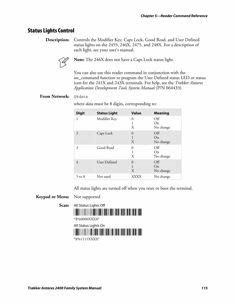
Chapter 5—Reader Command Reference
Trakker Antares 2400 Family System Manual 115
Status Lights Control Description: Controls the Modifier Key, Caps Lock, Good Read, and User Defined
status lights on the 2455, 246X, 2475, and 248X. For a description of each light, see your user’s manual.
Note: The 246X does not have a Caps Lock status light.
You can also use this reader command in conjunction with the im_command function to program the User Defined status LED or status icon for the 241X and 243X terminals. For help, see the Trakker Antares Application Development Tools System Manual (P/N 064433).
From Network: $%data
where data must be 8 digits, corresponding to:
Digit Status Light Value Meaning
1 Modifier Key 0 1 X
Off On No change
2 Caps Lock 0 1 X
Off On No change
3 Good Read 0 1 X
Off On No change
4 User Defined 0 1 X
Off On No change
5 to 8 Not used XXXX No change
All status lights are turned off when you reset or boot the terminal.
Keypad or Menu: Not supported
Scan: All Status Lights Off
*$%0000XXXX* *$%0000XXXX*
All Status Lights On
*$%1111XXXX* *$%1111XXXX*
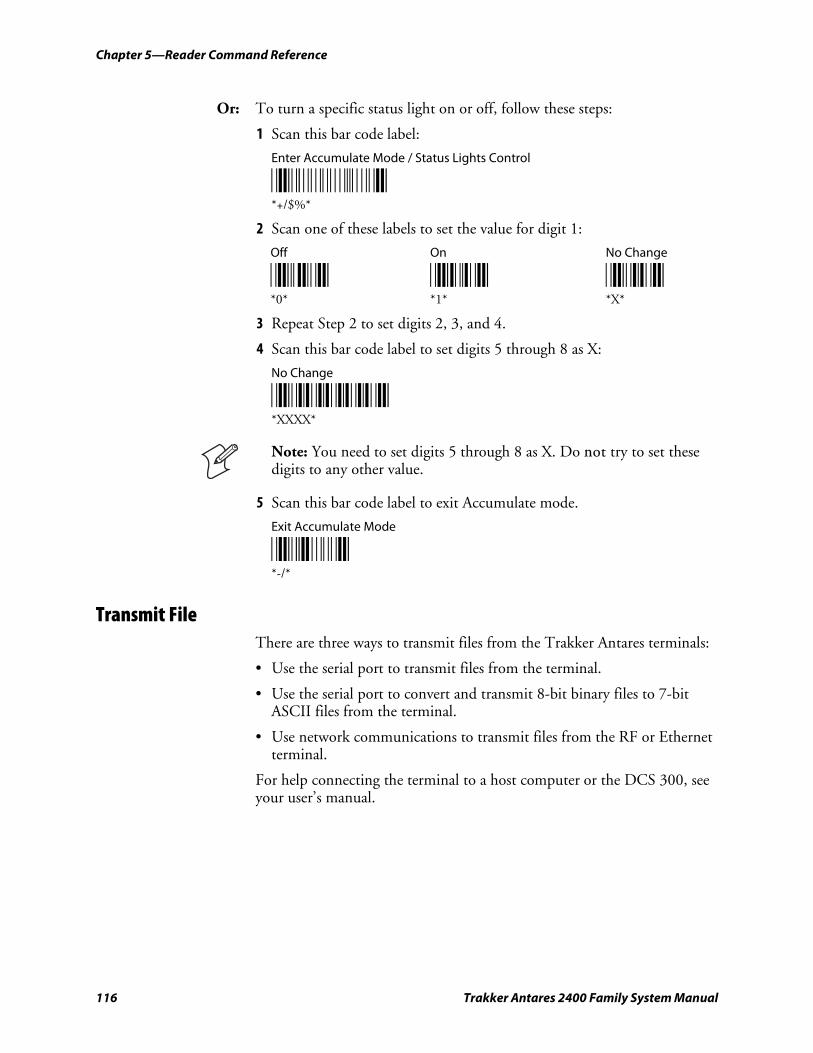
Chapter 5—Reader Command Reference
116 Trakker Antares 2400 Family System Manual
Or: To turn a specific status light on or off, follow these steps:
1 Scan this bar code label:
Enter Accumulate Mode / Status Lights Control
*+/$%* *+/$%*
2 Scan one of these labels to set the value for digit 1:
Off
*0* *0*
On
*1* *1*
No Change
*X* *X*
3 Repeat Step 2 to set digits 2, 3, and 4.
4 Scan this bar code label to set digits 5 through 8 as X:
No Change
*XXXX* *XXXX*
Note: You need to set digits 5 through 8 as X. Do not try to set these digits to any other value.
5 Scan this bar code label to exit Accumulate mode.
Exit Accumulate Mode
*-/* *-/*
Transmit File There are three ways to transmit files from the Trakker Antares terminals:
• Use the serial port to transmit files from the terminal.
• Use the serial port to convert and transmit 8-bit binary files to 7-bit ASCII files from the terminal.
• Use network communications to transmit files from the RF or Ethernet terminal.
For help connecting the terminal to a host computer or the DCS 300, see your user’s manual.
Chapter 5—Reader Command Reference
Trakker Antares 2400 Family System Manual 117
Transmit File Through the Serial Port Description: Transmits a file from the terminal through the serial port and saves it on
the host computer.
On the host, you must receive the file using a serial communications package (for example, Windows 3.1 Terminal, Win95 HyperTerminal, Crosstalk, or ProComm) that supports one of these protocols:
• XMODEM
• XMODEM-1K
• YMODEM
XMODEM-1K is a version of XMODEM that supports 1024-byte blocks as well as the standard 128-byte XMODEM data blocks, which increases the throughput. YMODEM has the additional ability to transfer a file name with the file’s data, and it preserves the length of the file without padding.
Note: Trakker Antares filenames are up to eight characters with a three-character extension. Files you transfer from the host must use the Trakker Antares naming conventions.
From Network: %%Xn,drive:filename Transmits a file using XMODEM protocol
%%Kn,drive:filename Transmits a file using XMODEM-1K protocol
%%Yn,drive:filename Transmits a file using YMODEM protocol
where:
%%X is the command to transmit a file using XMODEM protocol.
%%K is the command to transmit a file using XMODEM-1K protocol.
%%Y is the command to transmit a file using YMODEM protocol.
n indicates the terminal’s serial port: 1, 2, or 4.
drive: indicates the drive where the file is stored on the terminal. You must include the colon (:) after the drive letter.
filename is the file you want to transmit.
Keypad or Menu: Not supported
Note: To scan these bar code labels, you must configure the terminal to use Code 39 in Full ASCII mode. For help, see “Code 39” on page 146.
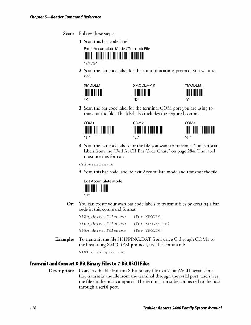
Chapter 5—Reader Command Reference
118 Trakker Antares 2400 Family System Manual
Scan: Follow these steps:
1 Scan this bar code label:
Enter Accumulate Mode / Transmit File
*/K/O/E/E* *+/%%*
2 Scan the bar code label for the communications protocol you want to use.
XMODEM XMODEM-1K YMODEM
*X* *K* *Y* *X* *K* *Y*
3 Scan the bar code label for the terminal COM port you are using to transmit the file. The label also includes the required comma.
COM1 COM2 COM4
*1/L* *2/L* *4/L* *1,* *2,* *4,*
4 Scan the bar code labels for the file you want to transmit. You can scan labels from the “Full ASCII Bar Code Chart” on page 284. The label must use this format:
drive:filename
5 Scan this bar code label to exit Accumulate mode and transmit the file.
Exit Accumulate Mode
*-/* *-/*
Or: You can create your own bar code labels to transmit files by creating a bar code in this command format:
%%Xn,drive:filename (for XMODEM)
%%Kn,drive:filename (for XMODEM-1K)
%%Yn,drive:filename (for YMODEM)
Example: To transmit the file SHIPPING.DAT from drive C through COM1 to the host using XMODEM protocol, use this command:
%%X1,c:shipping.dat
Transmit and Convert 8-Bit Binary Files to 7-Bit ASCII Files Description: Converts the file from an 8-bit binary file to a 7-bit ASCII hexadecimal
file, transmits the file from the terminal through the serial port, and saves the file on the host computer. The terminal must be connected to the host through a serial port.
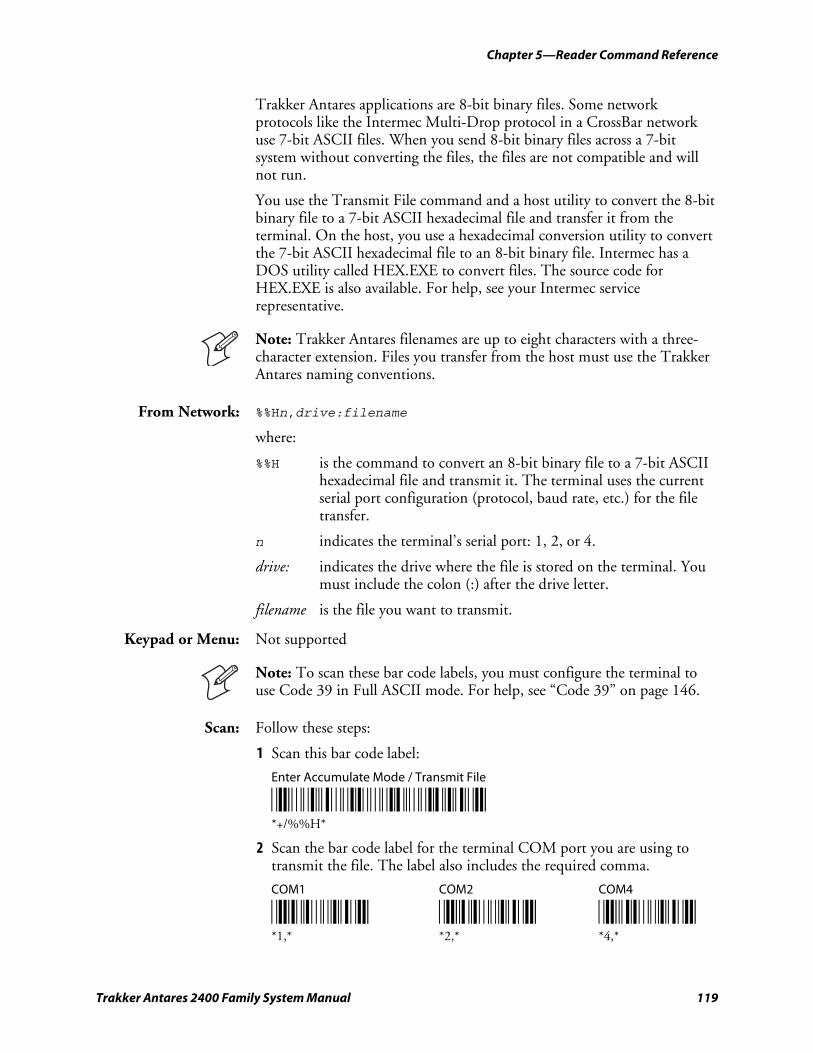
Chapter 5—Reader Command Reference
Trakker Antares 2400 Family System Manual 119
Trakker Antares applications are 8-bit binary files. Some network protocols like the Intermec Multi-Drop protocol in a CrossBar network use 7-bit ASCII files. When you send 8-bit binary files across a 7-bit system without converting the files, the files are not compatible and will not run.
You use the Transmit File command and a host utility to convert the 8-bit binary file to a 7-bit ASCII hexadecimal file and transfer it from the terminal. On the host, you use a hexadecimal conversion utility to convert the 7-bit ASCII hexadecimal file to an 8-bit binary file. Intermec has a DOS utility called HEX.EXE to convert files. The source code for HEX.EXE is also available. For help, see your Intermec service representative.
Note: Trakker Antares filenames are up to eight characters with a three-character extension. Files you transfer from the host must use the Trakker Antares naming conventions.
From Network: %%Hn,drive:filename
where:
%%H is the command to convert an 8-bit binary file to a 7-bit ASCII hexadecimal file and transmit it. The terminal uses the current serial port configuration (protocol, baud rate, etc.) for the file transfer.
n indicates the terminal’s serial port: 1, 2, or 4.
drive: indicates the drive where the file is stored on the terminal. You must include the colon (:) after the drive letter.
filename is the file you want to transmit.
Keypad or Menu: Not supported
Note: To scan these bar code labels, you must configure the terminal to use Code 39 in Full ASCII mode. For help, see “Code 39” on page 146.
Scan: Follow these steps:
1 Scan this bar code label:
Enter Accumulate Mode / Transmit File
*/K/O/E/EH* *+/%%H*
2 Scan the bar code label for the terminal COM port you are using to transmit the file. The label also includes the required comma.
COM1 COM2 COM4
*1/L* *2/L* *4/L* *1,* *2,* *4,*
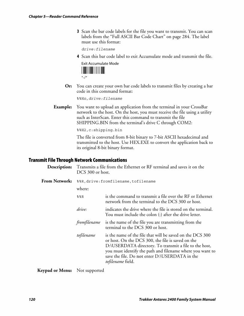
Chapter 5—Reader Command Reference
120 Trakker Antares 2400 Family System Manual
3 Scan the bar code labels for the file you want to transmit. You can scan labels from the “Full ASCII Bar Code Chart” on page 284. The label must use this format:
drive:filename
4 Scan this bar code label to exit Accumulate mode and transmit the file.
Exit Accumulate Mode
*-/* *-/*
Or: You can create your own bar code labels to transmit files by creating a bar code in this command format:
%%Hn,drive:filename
Example: You want to upload an application from the terminal in your CrossBar network to the host. On the host, you must receive the file using a utility such as InterScan. Enter this command to transmit the file SHIPPING.BIN from the terminal’s drive C through COM2:
%%H2,c:shipping.bin
The file is converted from 8-bit binary to 7-bit ASCII hexadecimal and transmitted to the host. Use HEX.EXE to convert the application back to its original 8-bit binary format.
Transmit File Through Network Communications Description: Transmits a file from the Ethernet or RF terminal and saves it on the
DCS 300 or host.
From Network: %%R,drive:fromfilename,tofilename
where:
%%R is the command to transmit a file over the RF or Ethernet network from the terminal to the DCS 300 or host.
drive: indicates the drive where the file is stored on the terminal. You must include the colon (:) after the drive letter.
fromfilename is the name of the file you are transmitting from the terminal to the DCS 300 or host.
tofilename is the name of the file that will be saved on the DCS 300 or host. On the DCS 300, the file is saved on the D:\USERDATA directory. To transmit a file to the host, you must identify the path and filename where you want to save the file. Do not enter D:\USERDATA in the tofilename field.
Keypad or Menu: Not supported
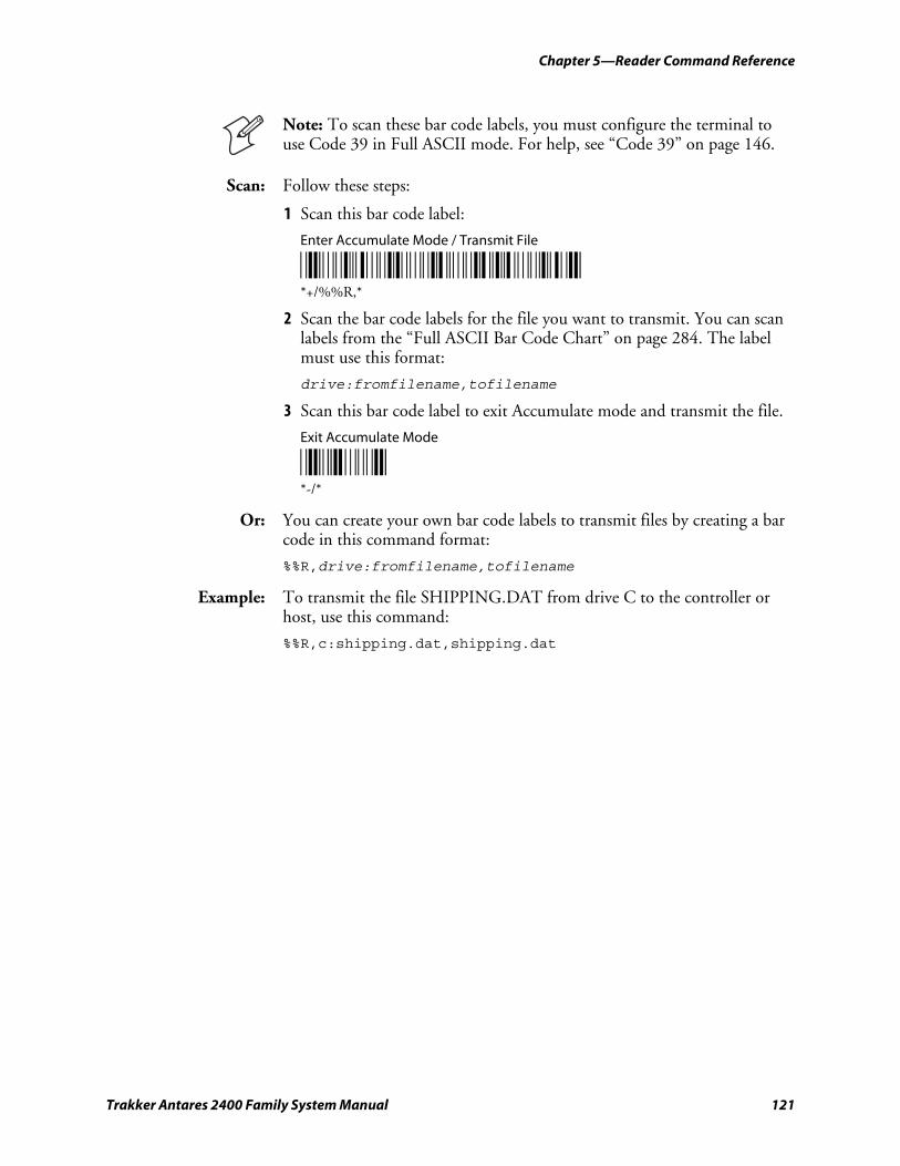
Chapter 5—Reader Command Reference
Trakker Antares 2400 Family System Manual 121
Note: To scan these bar code labels, you must configure the terminal to use Code 39 in Full ASCII mode. For help, see “Code 39” on page 146.
Scan: Follow these steps:
1 Scan this bar code label:
Enter Accumulate Mode / Transmit File
*/K/O/E/ER/L* *+/%%R,*
2 Scan the bar code labels for the file you want to transmit. You can scan labels from the “Full ASCII Bar Code Chart” on page 284. The label must use this format:
drive:fromfilename,tofilename
3 Scan this bar code label to exit Accumulate mode and transmit the file.
Exit Accumulate Mode
*-/* *-/*
Or: You can create your own bar code labels to transmit files by creating a bar code in this command format:
%%R,drive:fromfilename,tofilename
Example: To transmit the file SHIPPING.DAT from drive C to the controller or host, use this command:
%%R,c:shipping.dat,shipping.dat

Chapter 5—Reader Command Reference
122 Trakker Antares 2400 Family System Manual
Trakker Antares 2400 Family System Manual 123
Configuration Command Reference
This chapter describes all the configuration commands supported on the terminal and covers these topics:
• Using configuration commands
• Configuration commands listed by category
• Entering variable data in a configuration command
• Entering ASCII characters
• Defining configuration commands
6
Chapter 6—Configuration Command Reference
124 Trakker Antares 2400 Family System Manual
Using Configuration Commands A configuration command changes the way the terminal operates. For example, you can change the Beep Volume and make the terminal beep very loud in a noisy environment. You can execute configuration commands by:
• scanning a command from a Code 39 or Code 93 bar code label. Code 39 bar code labels are provided in this chapter. For help, see Chapter 2, “Configuring and Managing the Terminals.”
Note: If you are working in the TRAKKER Antares 2400 Menu System, you cannot scan configuration commands. Exit the menu system to scan configuration commands.
• choosing a command from the TRAKKER Antares 2400 Menu System. For help, see Chapter 2, “Configuring and Managing the Terminals.”
• sending a command from a device on the serial, RF, or Ethernet network. For help, see Chapter 2, “Configuring and Managing the Terminals.”
This chapter contains the following information about each configuration command:
• List of terminals that support the command
• Command description and purpose
• Command syntax and options
• Default setting
• Location within the TRAKKER Antares 2400 Menu System
• Bar code labels you can scan to set or change each command
The configuration commands are listed alphabetically by command name. For a list of commands sorted by category, use the next table, “Configuration Commands Listed by Category.” If you want to look up a command by its syntax, see “Configuration Commands by Syntax” starting on page 276.
Note: The Code 39 bar code labels in this chapter show an asterisk (*) at the beginning and end of the human-readable interpretation to represent the start and stop codes. If you are creating your own Code 39 bar code labels, your bar code printing utility may automatically supply the asterisks as the start/stop code.
Note: If you are using the advanced long range scanner or scan module, you may not be able to scan the bar code labels in this manual. However, you can still send commands through the serial port or network. For help, see Chapter 2, “Configuring and Managing the Terminals.”
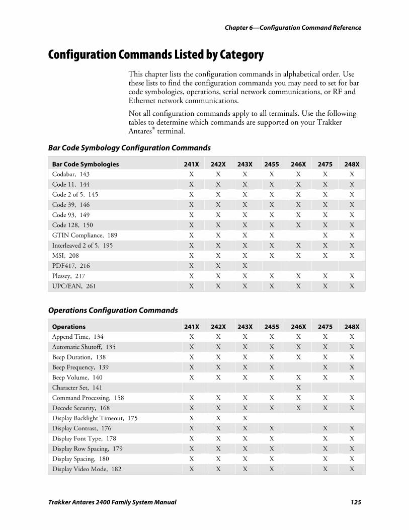
Chapter 6—Configuration Command Reference
Trakker Antares 2400 Family System Manual 125
Configuration Commands Listed by Category This chapter lists the configuration commands in alphabetical order. Use these lists to find the configuration commands you may need to set for bar code symbologies, operations, serial network communications, or RF and Ethernet network communications.
Not all configuration commands apply to all terminals. Use the following tables to determine which commands are supported on your Trakker Antares® terminal.
Bar Code Symbology Configuration Commands
Bar Code Symbologies 241X 242X 243X 2455 246X 2475 248X
Codabar, 143 X X X X X X X
Code 11, 144 X X X X X X X
Code 2 of 5, 145 X X X X X X X
Code 39, 146 X X X X X X X
Code 93, 149 X X X X X X X
Code 128, 150 X X X X X X X
GTIN Compliance, 189 X X X X X X
Interleaved 2 of 5, 195 X X X X X X X
MSI, 208 X X X X X X X
PDF417, 216 X X X
Plessey, 217 X X X X X X X
UPC/EAN, 261 X X X X X X X
Operations Configuration Commands
Operations 241X 242X 243X 2455 246X 2475 248X
Append Time, 134 X X X X X X X
Automatic Shutoff, 135 X X X X X X X
Beep Duration, 138 X X X X X X X
Beep Frequency, 139 X X X X X X
Beep Volume, 140 X X X X X X X
Character Set, 141 X
Command Processing, 158 X X X X X X X
Decode Security, 168 X X X X X X X
Display Backlight Timeout, 175 X X X
Display Contrast, 176 X X X X X X
Display Font Type, 178 X X X X X X
Display Row Spacing, 179 X X X X X X
Display Spacing, 180 X X X X X X
Display Video Mode, 182 X X X X X X
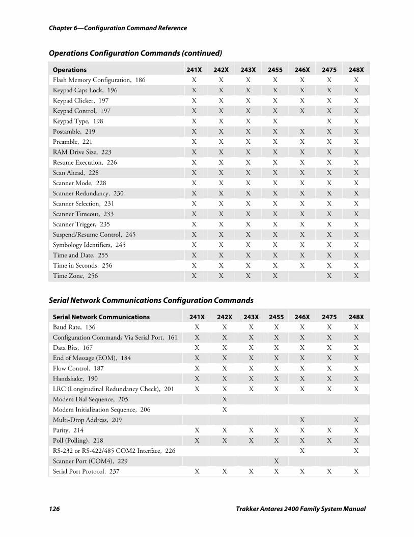
Chapter 6—Configuration Command Reference
126 Trakker Antares 2400 Family System Manual
Operations Configuration Commands (continued)
Operations 241X 242X 243X 2455 246X 2475 248X
Flash Memory Configuration, 186 X X X X X X X
Keypad Caps Lock, 196 X X X X X X X
Keypad Clicker, 197 X X X X X X X
Keypad Control, 197 X X X X X X X
Keypad Type, 198 X X X X X X
Postamble, 219 X X X X X X X
Preamble, 221 X X X X X X X
RAM Drive Size, 223 X X X X X X X
Resume Execution, 226 X X X X X X X
Scan Ahead, 228 X X X X X X X
Scanner Mode, 228 X X X X X X X
Scanner Redundancy, 230 X X X X X X X
Scanner Selection, 231 X X X X X X X
Scanner Timeout, 233 X X X X X X X
Scanner Trigger, 235 X X X X X X X
Suspend/Resume Control, 245 X X X X X X X
Symbology Identifiers, 245 X X X X X X X
Time and Date, 255 X X X X X X X
Time in Seconds, 256 X X X X X X X
Time Zone, 256 X X X X X X
Serial Network Communications Configuration Commands
Serial Network Communications 241X 242X 243X 2455 246X 2475 248X
Baud Rate, 136 X X X X X X X
Configuration Commands Via Serial Port, 161 X X X X X X X
Data Bits, 167 X X X X X X X
End of Message (EOM), 184 X X X X X X X
Flow Control, 187 X X X X X X X
Handshake, 190 X X X X X X X
LRC (Longitudinal Redundancy Check), 201 X X X X X X X
Modem Dial Sequence, 205 X
Modem Initialization Sequence, 206 X
Multi-Drop Address, 209 X X
Parity, 214 X X X X X X X
Poll (Polling), 218 X X X X X X X
RS-232 or RS-422/485 COM2 Interface, 226 X X
Scanner Port (COM4), 229 X
Serial Port Protocol, 237 X X X X X X X
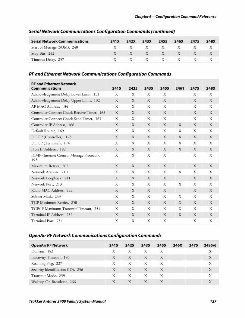
Chapter 6—Configuration Command Reference
Trakker Antares 2400 Family System Manual 127
Serial Network Communications Configuration Commands (continued)
Serial Network Communications 241X 242X 243X 2455 246X 2475 248X
Start of Message (SOM), 240 X X X X X X X
Stop Bits, 242 X X X X X X X
Timeout Delay, 257 X X X X X X X
RF and Ethernet Network Communications Configuration Commands
RF and Ethernet Network Communications
2415
2425
2435
2455
2461
2475
248X
Acknowledgement Delay Lower Limit, 131 X X X X X X
Acknowledgement Delay Upper Limit, 132 X X X X X X
AP MAC Address, 134 X X X X X X
Controller Connect Check Receive Timer, 163 X X X X X X
Controller Connect Check Send Timer, 164 X X X X X X
Controller IP Address, 166 X X X X X X X
Default Router, 169 X X X X X X X
DHCP (Controller), 173 X X X X X X X
DHCP (Terminal), 174 X X X X X X X
Host IP Address, 192 X X X X X X X
ICMP (Internet Control Message Protocol), 193
X X X X X X
Maximum Retries, 202 X X X X X X
Network Activate, 210 X X X X X X X
Network Loopback, 211 X X X X X X
Network Port, 213 X X X X X X X
Radio MAC Address, 222 X X X X X X
Subnet Mask, 243 X X X X X X X
TCP Maximum Retries, 250 X X X X X X X
TCP/IP Maximum Transmit Timeout, 251 X X X X X X X
Terminal IP Address, 252 X X X X X X X
Terminal Port, 254 X X X X X X
OpenAir RF Network Communications Configuration Commands
OpenAir RF Network 2415 2425 2435 2455 246X 2475 2485/6
Domain, 183 X X X X X
Inactivity Timeout, 193 X X X X X
Roaming Flag, 227 X X X X X
Security Identification (ID), 236 X X X X X
Transmit Mode, 259 X X X X X
Wakeup On Broadcast, 266 X X X X X
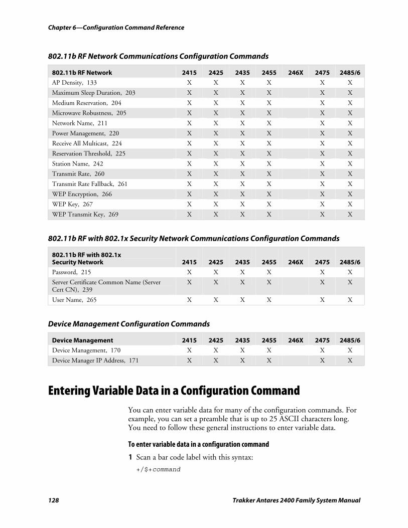
Chapter 6—Configuration Command Reference
128 Trakker Antares 2400 Family System Manual
802.11b RF Network Communications Configuration Commands
802.11b RF Network 2415 2425 2435 2455 246X 2475 2485/6
AP Density, 133 X X X X X X
Maximum Sleep Duration, 203 X X X X X X
Medium Reservation, 204 X X X X X X
Microwave Robustness, 205 X X X X X X
Network Name, 211 X X X X X X
Power Management, 220 X X X X X X
Receive All Multicast, 224 X X X X X X
Reservation Threshold, 225 X X X X X X
Station Name, 242 X X X X X X
Transmit Rate, 260 X X X X X X
Transmit Rate Fallback, 261 X X X X X X
WEP Encryption, 266 X X X X X X
WEP Key, 267 X X X X X X
WEP Transmit Key, 269 X X X X X X
802.11b RF with 802.1x Security Network Communications Configuration Commands
802.11b RF with 802.1x Security Network
2415
2425
2435
2455
246X
2475
2485/6
Password, 215 X X X X X X
Server Certificate Common Name (Server Cert CN), 239
X X X X X X
User Name, 265 X X X X X X
Device Management Configuration Commands
Device Management 2415 2425 2435 2455 246X 2475 2485/6
Device Management, 170 X X X X X X
Device Manager IP Address, 171 X X X X X X
Entering Variable Data in a Configuration Command You can enter variable data for many of the configuration commands. For example, you can set a preamble that is up to 25 ASCII characters long. You need to follow these general instructions to enter variable data.
To enter variable data in a configuration command
1 Scan a bar code label with this syntax:
+/$+command
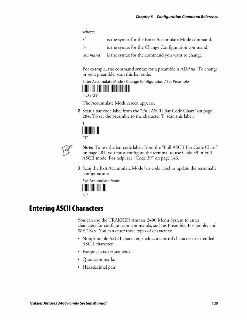
Chapter 6—Configuration Command Reference
Trakker Antares 2400 Family System Manual 129
where:
+/ is the syntax for the Enter Accumulate Mode command.
$+ is the syntax for the Change Configuration command.
command is the syntax for the command you want to change.
For example, the command syntax for a preamble is ADdata. To change or set a preamble, scan this bar code:
Enter Accumulate Mode / Change Configuration / Set Preamble
*+/$+AD* *+/$+AD*
The Accumulate Mode screen appears.
2 Scan a bar code label from the “Full ASCII Bar Code Chart” on page 284. To set the preamble to the character T, scan this label:
T
*T* *T*
Note: To use the bar code labels from the “Full ASCII Bar Code Chart” on page 284, you must configure the terminal to use Code 39 in Full ASCII mode. For help, see “Code 39” on page 146.
3 Scan the Exit Accumulate Mode bar code label to update the terminal’s configuration:
Exit Accumulate Mode
*-/* *-/*
Entering ASCII Characters You can use the TRAKKER Antares 2400 Menu System to enter characters for configuration commands, such as Preamble, Postamble, and WEP Key. You can enter these types of characters:
• Nonprintable ASCII character, such as a control character or extended ASCII character
• Escape character sequence
• Quotation marks
• Hexadecimal pair
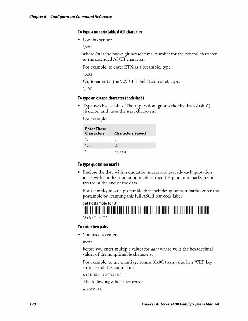
Chapter 6—Configuration Command Reference
130 Trakker Antares 2400 Family System Manual
To type a nonprintable ASCII character
• Use this syntax:
\xhh
where hh is the two-digit hexadecimal number for the control character or the extended ASCII character.
For example, to enter ETX as a preamble, type:
\x03
Or, to enter Ü (the 5250 TE Field Exit code), type:
\x9A
To type an escape character (backslash)
• Type two backslashes. The application ignores the first backslash (\) character and saves the next characters.
For example:
Enter These Characters
Characters Saved
\\ \
\\k \k
\ no data
To type quotation marks
• Enclose the data within quotation marks and precede each quotation mark with another quotation mark so that the quotation marks are not treated as the end of the data.
For example, to set a postamble that includes quotation marks, enter the postamble by scanning this full ASCII bar code label:
Set Postamble to “B”
*/D/KAE/B/B/BB/B/B/B* *$+AE"""B"""*
To enter hex pairs
• You need to enter:
0xnn
before you enter multiple values for data where nn is the hexadecimal values of the nonprintable characters.
For example, to use a carriage return (0x0C) as a value in a WEP key string, send this command:
$+LM0X41420D4142
The following value is returned:
AB<cr>AB
Chapter 6—Configuration Command Reference
Trakker Antares 2400 Family System Manual 131
Acknowledgement Delay Lower Limit
Terminals: 2415, 2425, 2435, 2455, 2475, and 2485/6.
Description: When the terminal sends a message to the Intermec Gateway or DCS 30X, the terminal waits to receive a response acknowledging the message. If no response is received within the acknowledgement delay lower limit time, the terminal sends the message again at the time interval set for the lower limit. The terminal will continue to send the data at increasingly longer intervals until it reaches the acknowledgement delay upper limit time. The terminal continues sending the message at the time interval set for the upper limit until a response is received or a timeout error occurs.
Syntax: NVdata
Acceptable values for data are any number from 200 to 2000 ms.
Default: 300 ms
Menu System: Main Menu > Configuration Menu > Communications Menu > Advanced Network
Bar Codes: To set the default acknowledgement delay lower limit, scan this bar code:
Default Acknowledgement Delay Lower Limit
*$+NV300* *$+NV300*
Or: To set the acknowledgement delay lower limit:
1 Scan this bar code:
Enter Accumulate Mode / Set Acknowledgement Delay Lower Limit
*+/$+NV* *+/$+NV*
2 Scan a numeric value for data from these bar codes:
*0* *1* *0* *1*
*2* *3* *2* *3*
*4* *5* *4* *5*
*6* *7* *6* *7*
*8* *9* *8* *9*
Chapter 6—Configuration Command Reference
132 Trakker Antares 2400 Family System Manual
3 Scan this bar code:
Exit Accumulate Mode
*-/* *-/*
Acknowledgement Delay Upper Limit
Terminals: 2415, 2425, 2435, 2455, 2475, and 2485/6.
Description: When the terminal sends a message to the Intermec Gateway or DCS 30X, the terminal waits to receive a response acknowledging the message. If no response is received within the Acknowledgement Delay Lower Limit time, the terminal sends the message again at the time interval set for the lower limit. The terminal will continue to send the data at increasingly longer intervals until it reaches the Acknowledgement Delay Upper Limit time. The terminal continues sending the message at the time interval set for the upper limit until a response is received or a timeout error occurs.
Syntax: NUdata
Acceptable values for data are any number from 2000 to 60000 ms.
Default: 5000 ms
Menu System: Main Menu > Configuration Menu > Communications Menu > Advanced Network
Bar Codes: To set the default acknowledgement delay upper limit, scan this bar code:
Default Acknowledgement Delay Upper Limit
*$+NU5000* *$+NU5000*
Or: To set the acknowledgement delay upper limit:
1 Scan this bar code:
Enter Accumulate Mode / Set Acknowledgement Delay Upper Limit
*+/$+NU* *+/$+NU*
2 Scan a numeric value for data from these bar codes:
*0* *1* *0* *1*
*2* *3* *2* *3*
Chapter 6—Configuration Command Reference
Trakker Antares 2400 Family System Manual 133
*4* *5* *4* *5*
*6* *7* *6* *7*
*8* *9* *8* *9*
3 Scan this bar code:
Exit Accumulate Mode
*-/* *-/*
AP Density
Terminals: 2415, 2425, 2435, 2455, 2475, and 2485/6 with 802.11b radios.
Description: Controls the roaming sensitivity of the radios. You can use this parameter to virtually reduce the range of the radio. When you increase the AP density, you do not reduce the absolute range of the radio, but the roaming algorithms are modified to allow significant overlap of the radio coverage. Increasing the AP density lets you create a higher performance radio network, but you will need significantly more access points to cover a given area.
Syntax: LGdata
Acceptable values for data are:
1 Low density 2 Medium density 3 High density
Default: Low density
Menu System: Main Menu > Configuration Menu > Communications Menu > Radio
Bar Codes: Scan one of these bar codes:
Low AP Density Medium AP Density
*$+LG1* *$+LG2* *$+LG1* *$+LG2*
High AP Density
*$+LG3* *$+LG3*
Chapter 6—Configuration Command Reference
134 Trakker Antares 2400 Family System Manual
AP MAC Address
Terminals: 2415, 2425, 2435, 2455, 2475, and 2485/6.
Description: Returns the MAC address of the radio that is installed in the access point that the terminal is communicating with. You can only use this read-only command in an application to return the value (MAC address) to the application.
Syntax: RA
Default: None
Menu System: N/A
Bar Codes: N/A
Append Time
Terminals: All Trakker Antares terminals.
Description: Appends the time to bar code labels that are scanned into the terminal. You can also use the Time in Seconds command to append the time in hours and minutes only, or hours, minutes, and seconds. The time is appended to the data in the form HH:MM:SS. For help, see “Time in Seconds” on page 256.
Syntax: DEdata
Acceptable values for data are:
0 Disabled 1 Enabled
Default: Disabled
Menu System: Main Menu > Configuration Menu > Terminal Menu > Append Time
Bar Codes: Scan one of these bar codes:
Disable Append Time Enable Append Time
*$+DE0* *$+DE1* *$+DE0* *$+DE1*
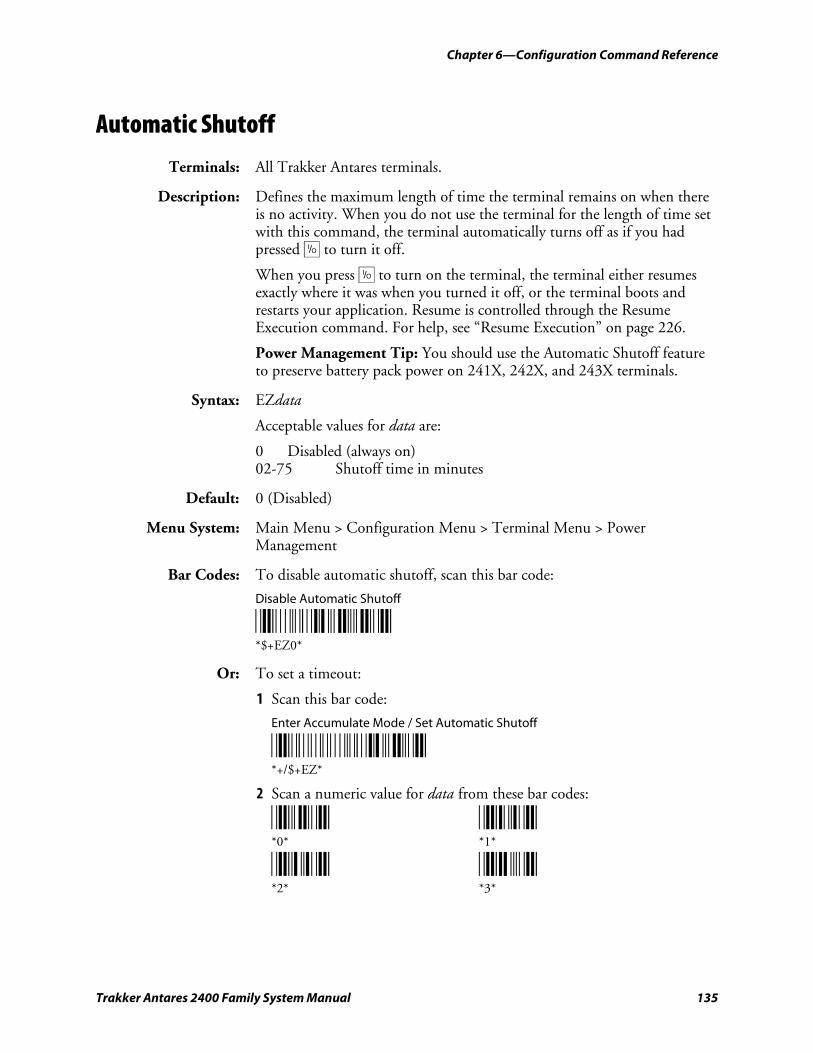
Chapter 6—Configuration Command Reference
Trakker Antares 2400 Family System Manual 135
Automatic Shutoff
Terminals: All Trakker Antares terminals.
Description: Defines the maximum length of time the terminal remains on when there is no activity. When you do not use the terminal for the length of time set with this command, the terminal automatically turns off as if you had pressed œ to turn it off.
When you press œ to turn on the terminal, the terminal either resumes exactly where it was when you turned it off, or the terminal boots and restarts your application. Resume is controlled through the Resume Execution command. For help, see “Resume Execution” on page 226.
Power Management Tip: You should use the Automatic Shutoff feature to preserve battery pack power on 241X, 242X, and 243X terminals.
Syntax: EZdata
Acceptable values for data are:
0 Disabled (always on) 02-75 Shutoff time in minutes
Default: 0 (Disabled)
Menu System: Main Menu > Configuration Menu > Terminal Menu > Power Management
Bar Codes: To disable automatic shutoff, scan this bar code:
Disable Automatic Shutoff
*$+EZ0* *$+EZ0*
Or: To set a timeout:
1 Scan this bar code:
Enter Accumulate Mode / Set Automatic Shutoff
*+/$+EZ* *+/$+EZ*
2 Scan a numeric value for data from these bar codes:
*0* *1* *0* *1*
*2* *3* *2* *3*
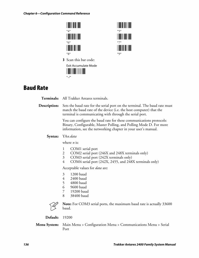
Chapter 6—Configuration Command Reference
136 Trakker Antares 2400 Family System Manual
*4* *5* *4* *5*
*6* *7* *6* *7*
*8* *9* *8* *9*
3 Scan this bar code:
Exit Accumulate Mode
*-/* *-/*
Baud Rate
Terminals: All Trakker Antares terminals.
Description: Sets the baud rate for the serial port on the terminal. The baud rate must match the baud rate of the device (i.e. the host computer) that the terminal is communicating with through the serial port.
You can configure the baud rate for these communications protocols: Binary, Configurable, Master Polling, and Polling Mode D. For more information, see the networking chapter in your user’s manual.
Syntax: YAn.data
where n is:
1 COM1 serial port 2 COM2 serial port (246X and 248X terminals only) 3 COM3 serial port (242X terminals only) 4 COM4 serial port (242X, 2455, and 248X terminals only)
Acceptable values for data are:
3 1200 baud 4 2400 baud 5 4800 baud 6 9600 baud 7 19200 baud 8 38400 baud
Note: For COM3 serial ports, the maximum baud rate is actually 33600 baud.
Default: 19200
Menu System: Main Menu > Configuration Menu > Communications Menu > Serial Port
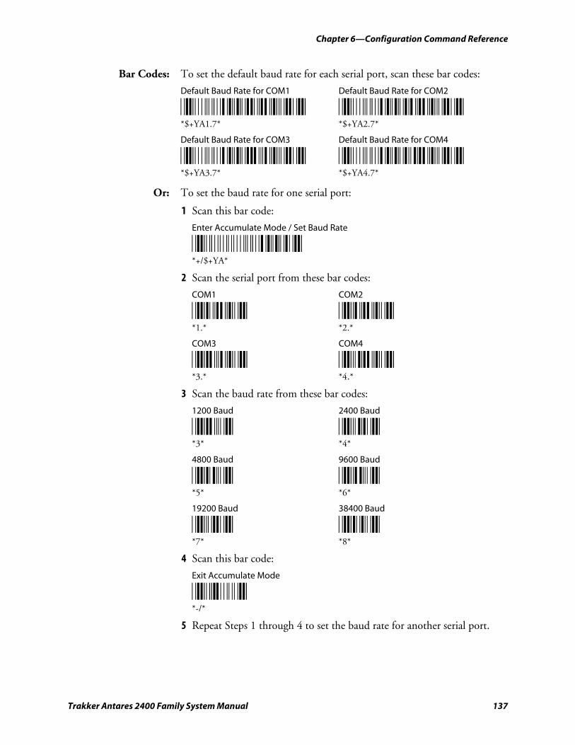
Chapter 6—Configuration Command Reference
Trakker Antares 2400 Family System Manual 137
Bar Codes: To set the default baud rate for each serial port, scan these bar codes:
Default Baud Rate for COM1 Default Baud Rate for COM2
*$+YA1.7* *$+YA2.7* *$+YA1.7* *$+YA2.7*
Default Baud Rate for COM3 Default Baud Rate for COM4
*$+YA3.7* *$+YA4.7* *$+YA3.7* *$+YA4.7*
Or: To set the baud rate for one serial port:
1 Scan this bar code:
Enter Accumulate Mode / Set Baud Rate
*+/$+YA* *+/$+YA*
2 Scan the serial port from these bar codes:
COM1 COM2
*1.* *2.* *1.* *2.*
COM3 COM4
*3.* *4.* *3.* *4.*
3 Scan the baud rate from these bar codes:
1200 Baud 2400 Baud
*3* *4* *3* *4*
4800 Baud 9600 Baud
*5* *6* *5* *6*
19200 Baud 38400 Baud
*7* *8* *7* *8*
4 Scan this bar code:
Exit Accumulate Mode
*-/* *-/*
5 Repeat Steps 1 through 4 to set the baud rate for another serial port.
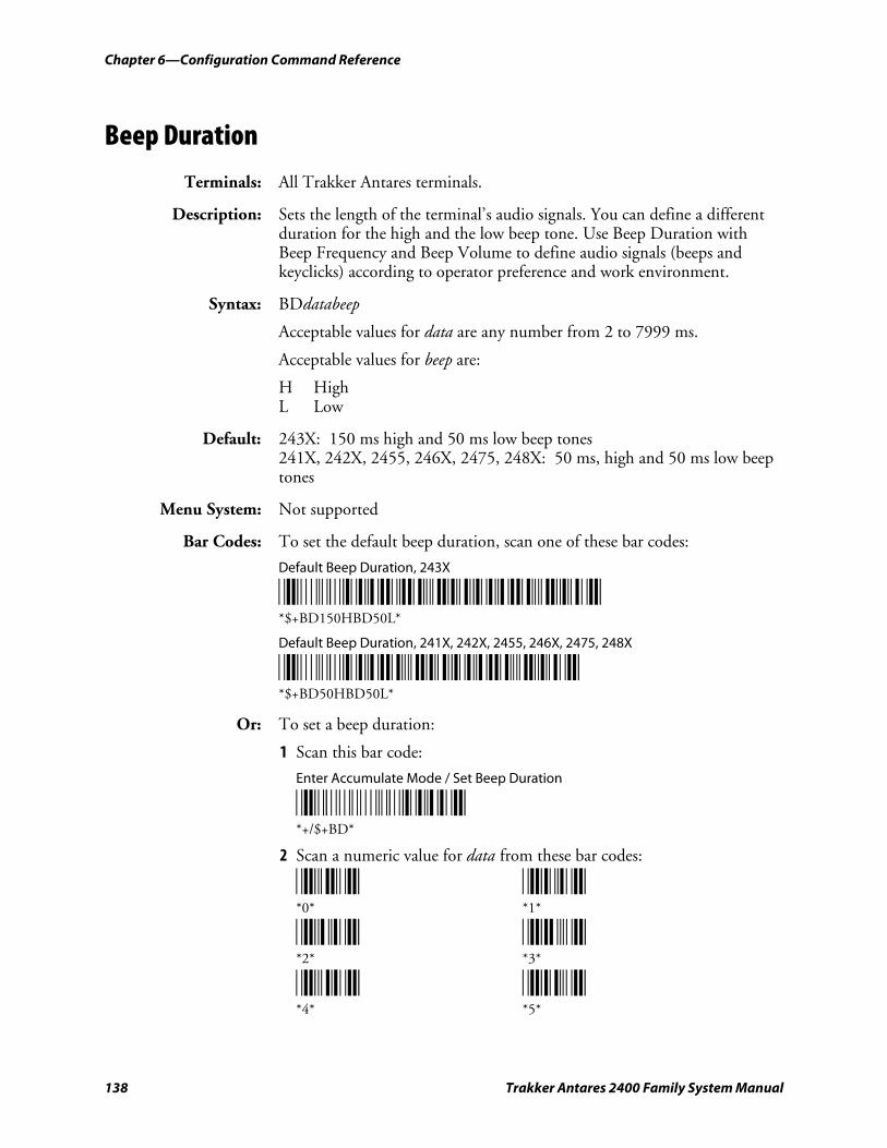
Chapter 6—Configuration Command Reference
138 Trakker Antares 2400 Family System Manual
Beep Duration
Terminals: All Trakker Antares terminals.
Description: Sets the length of the terminal’s audio signals. You can define a different duration for the high and the low beep tone. Use Beep Duration with Beep Frequency and Beep Volume to define audio signals (beeps and keyclicks) according to operator preference and work environment.
Syntax: BDdatabeep
Acceptable values for data are any number from 2 to 7999 ms.
Acceptable values for beep are:
H High L Low
Default: 243X: 150 ms high and 50 ms low beep tones 241X, 242X, 2455, 246X, 2475, 248X: 50 ms, high and 50 ms low beep tones
Menu System: Not supported
Bar Codes: To set the default beep duration, scan one of these bar codes:
Default Beep Duration, 243X
*$+BD150HBD50L* *$+BD150HBD50L*
Default Beep Duration, 241X, 242X, 2455, 246X, 2475, 248X
*$+BD50HBD50L* *$+BD50HBD50L*
Or: To set a beep duration:
1 Scan this bar code:
Enter Accumulate Mode / Set Beep Duration
*+/$+BD* *+/$+BD*
2 Scan a numeric value for data from these bar codes:
*0* *1* *0* *1*
*2* *3* *2* *3*
*4* *5* *4* *5*
Chapter 6—Configuration Command Reference
Trakker Antares 2400 Family System Manual 139
*6* *7* *6* *7*
*8* *9* *8* *9*
3 Scan the beep tone for which you are setting the beep duration:
High Low
*H* *L* *H* *L*
4 Scan this bar code:
Exit Accumulate Mode
*-/* *-/*
Beep Frequency
Terminals: 241X, 242X, 243X, 2455, 2475, and 248X.
Description: Sets the frequency, or pitch, of the terminal’s audio signals. Use Beep Frequency with Beep Duration and Beep Volume to define audio signals (beeps and keyclicks) according to operator preference and work environment.
Note: The beep frequency response varies between terminals. You may need to test several beep frequencies to find the optimal frequency for the operator and work environment.
Syntax: BFdatabeep
Acceptable values for data are any number from 20 to 8000 Hz.
Acceptable values for beep are:
H High L Low
Default: 241X: 2400 Hz high, 1400 Hz low 243X: 1900 Hz high, 1050 Hz low 242X, 2455, 246X, 2475, 248X: 2400 Hz high, 1200 Hz low
Menu System: Not supported
Bar Codes: To set the default beep frequency, scan one of these bar codes:
Default Beep Frequency, 241X
*$+BF2400HBF1400L* *$+BF2400HBF1400L*

Chapter 6—Configuration Command Reference
140 Trakker Antares 2400 Family System Manual
Default Beep Frequency, 243X
*$+BF1900HBF1050L* *$+BF1900HBF1050L*
Default Beep Frequency, 242X, 2455, 246X, 2475, 248X
*$+BF2400HBF1200L* *$+BF2400HBF1200L*
Or: To set a beep frequency:
1 Scan this bar code:
Enter Accumulate Mode / Set Beep Frequency
*+/$+BF* *+/$+BF*
2 Scan a numeric value for data from these bar codes:
*0* *1* *0* *1*
*2* *3* *2* *3*
*4* *5* *4* *5*
*6* *7* *6* *7*
*8* *9* *8* *9*
3 Scan the beep tone for which you are setting the beep frequency:
High Low
*H* *L* *H* *L*
4 Scan this bar code:
Exit Accumulate Mode
*-/* *-/*
Beep Volume
Terminals: All Trakker Antares terminals.
Description: Adjusts the volume of the terminal’s audio signals. Use Beep Volume with Beep Duration and Beep Frequency to define audio signals (beeps and keyclicks) according to operator preference and work environment.
Chapter 6—Configuration Command Reference
Trakker Antares 2400 Family System Manual 141
If you set the Beep Volume command to off, you will not hear any audio signals including the keyclick.
Syntax: BVdata
Acceptable values for data are:
0 Off 1 Quiet 2 Normal 3 Loud 4 Very loud 8 Lower volume 9 Raise volume
Default: Very loud
Menu System: Main Menu > Configuration Menu > Terminal Menu > Beeper
Bar Codes: Scan one of these bar codes:
Beep Volume Off Beep Volume Quiet
*$+BV0* *$+BV1* *$+BV0* *$+BV1*
Beep Volume Normal Beep Volume Loud
*$+BV2* *$+BV3* *$+BV2* *$+BV3*
Beep Volume Very Loud
*$+BV4* *$+BV4*
Or: Scan one of these bar codes repeatedly to change the beep volume:
Lower Beep Volume Raise Beep Volume
*$+BV8* *$+BV9* *$+BV8* *$+BV9*
Character Set
Terminals: 246X.
Description: Determines the language used to display characters.
Syntax: DXdata
Acceptable values for data are:
0 U.S. ASCII 1 French 2 German 3 United Kingdom
Chapter 6—Configuration Command Reference
142 Trakker Antares 2400 Family System Manual
4 Danish / Norwegian 5 Swedish 6 Italian 7 Spanish
Default: U.S. ASCII
Menu System: N/A
Bar Codes: Scan one of these bar code labels:
U.S. ASCII Character Set French Character Set
*$+DX0* *$+DX1* *$+DX0* *$+DX1*
German Character Set United Kingdom Character Set
*$+DX2* *$+DX3* *$+DX2* *$+DX3*
Danish Character Set Swedish Character Set
*$+DX4* *$+DX5* *$+DX4* *$+DX5*
Italian Character Set Spanish Character Set
*$+DX6* *$+DX7* *$+DX6* *$+DX7*
The next table lists the ASCII characters that change for the seven European languages. Only these 11 characters change in any character set. All other characters in the ASCII chart remain as defined in the “Full ASCII Table” on page 284.
ASCII Character Changes for Character Sets
Hexadecimal Value
Country 23 40 5B 5C 5D 5E 60 7B 7C 7D 7E
United States # @ [ \ ] ^ ' { | } ~ England £ @ [ \ ] ^ ' { ¦ } ~ Germany # § Ä Ö Ü ^ ' ä ö ü ß
Denmark # @ Æ Ø Å ^ ' æ ø å ~ France # à ° ç § ^ ' é ù è ¨ Sweden # É Ä Ö Å Ü é ä ö å ü Italy # @ ° ç é ^ ù à ò è ì Spain @ ¡ Ñ ¿ ^ ' ¨ ñ } ~
Chapter 6—Configuration Command Reference
Trakker Antares 2400 Family System Manual 143
Codabar
Terminals: All Trakker Antares terminals.
Description: Enables or disables decoding of Codabar symbology. Codabar is a self-checking, discrete symbology. The American Blood Commission (ABC) Codabar requires that you retain and transmit the start/stop code digits when processing a Codabar symbol. As a result, configuration CD10 is an illegal configuration.
Syntax: CDdata
Acceptable values for data must be two digits, corresponding to:
Digit 1: 0 Disabled
1 ABC
2 Standard
3 Concatenated
Digit 2: 0 Discard Start/Stop
1 Transmit ABCD Start/Stop
2 Transmit DC1-DC4 Start/Stop
Note: Concatenated is not supported on terminals with an integrated E1022 linear imager or an integrated PDF417 scan engine.
Default: Disabled
Menu System: Main Menu > Configuration Menu > Symbologies Menu
Bar Codes: Scan one of these bar codes:
Disabled, Discard Start/Stop ABC, Transmit ABCD Start/Stop
*$+CD00* *$+CD11* *$+CD00* *$+CD11*
ABC, Transmit DC1-DC4 Start/Stop Standard, Discard Start/Stop
*$+CD12* *$+CD20* *$+CD12* *$+CD20*
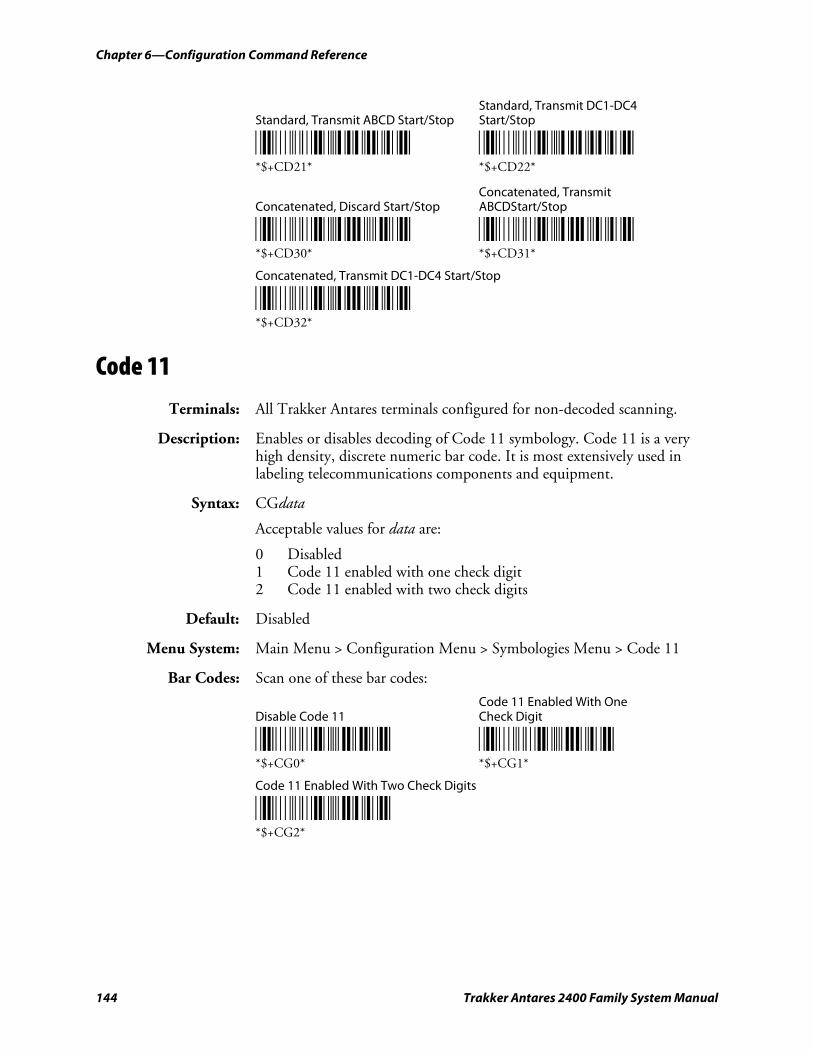
Chapter 6—Configuration Command Reference
144 Trakker Antares 2400 Family System Manual
Standard, Transmit DC1-DC4 Standard, Transmit ABCD Start/Stop Start/Stop
*$+CD21* *$+CD22* *$+CD21* *$+CD22*
Concatenated, Transmit Concatenated, Discard Start/Stop ABCDStart/Stop
*$+CD30* *$+CD31* *$+CD30* *$+CD31*
Concatenated, Transmit DC1-DC4 Start/Stop
*$+CD32* *$+CD32*
Code 11
Terminals: All Trakker Antares terminals configured for non-decoded scanning.
Description: Enables or disables decoding of Code 11 symbology. Code 11 is a very high density, discrete numeric bar code. It is most extensively used in labeling telecommunications components and equipment.
Syntax: CGdata
Acceptable values for data are:
0 Disabled 1 Code 11 enabled with one check digit 2 Code 11 enabled with two check digits
Default: Disabled
Menu System: Main Menu > Configuration Menu > Symbologies Menu > Code 11
Bar Codes: Scan one of these bar codes:
Code 11 Enabled With One Disable Code 11 Check Digit
*$+CG0* *$+CG1* *$+CG0* *$+CG1*
Code 11 Enabled With Two Check Digits
*$+CG2* *$+CG2*
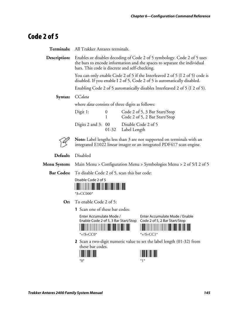
Chapter 6—Configuration Command Reference
Trakker Antares 2400 Family System Manual 145
Code 2 of 5
Terminals: All Trakker Antares terminals.
Description: Enables or disables decoding of Code 2 of 5 symbology. Code 2 of 5 uses the bars to encode information and the spaces to separate the individual bars. This code is discrete and self-checking.
You can only enable Code 2 of 5 if the Interleaved 2 of 5 (I 2 of 5) code is disabled. If you enable I 2 of 5, Code 2 of 5 is automatically disabled.
Enabling Code 2 of 5 automatically disables Interleaved 2 of 5 (I 2 of 5).
Syntax: CCdata
where data consists of three digits as follows:
Digit 1: 0 Code 2 of 5, 3 Bar Start/Stop 1 Code 2 of 5, 2 Bar Start/Stop
Digits 2 and 3: 00 Disable Code 2 of 5 01-32 Label Length
Note: Label lengths less than 3 are not supported on terminals with an integrated E1022 linear imager or an integrated PDF417 scan engine.
Default: Disabled
Menu System: Main Menu > Configuration Menu > Symbologies Menu > 2 of 5/I 2 of 5
Bar Codes: To disable Code 2 of 5, scan this bar code:
Disable Code 2 of 5
*$+CC000* *$+CC000*
Or: To enable Code 2 of 5:
1 Scan one of these bar codes:
Enter Accumulate Mode / Enter Accumulate Mode / Enable Enable Code 2 of 5, 3 Bar Start/Stop Code 2 of 5, 2 Bar Start/Stop
*+/$+CC0* *+/$+CC1* *+/$+CC0* *+/$+CC1*
2 Scan a two-digit numeric value to set the label length (01-32) from these bar codes.
*0* *1* *0* *1*
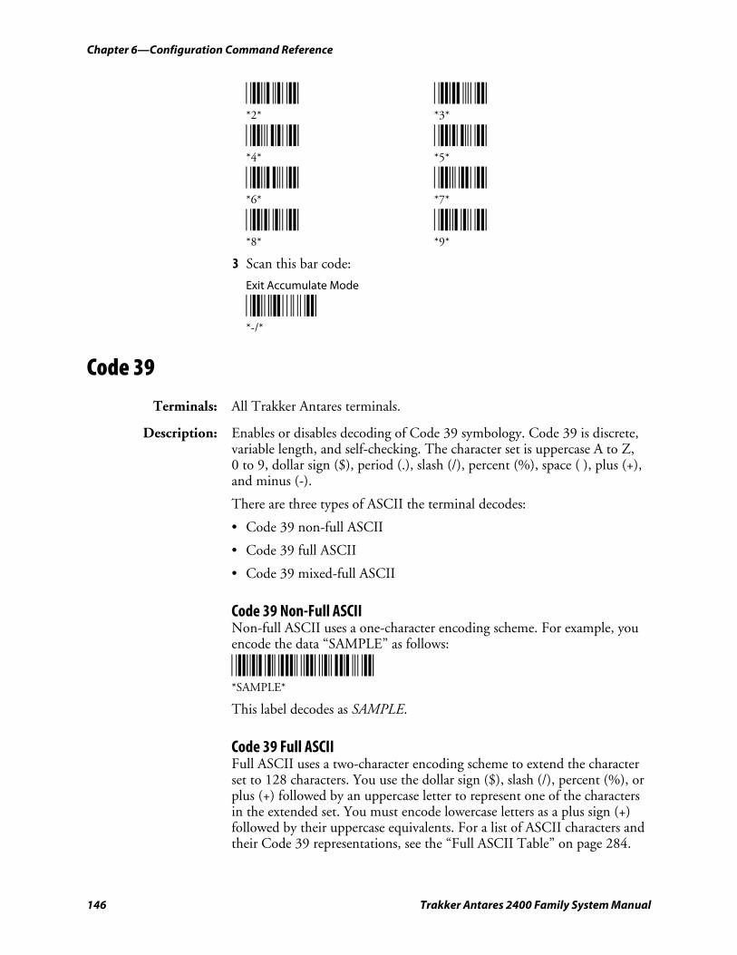
Chapter 6—Configuration Command Reference
146 Trakker Antares 2400 Family System Manual
*2* *3* *2* *3*
*4* *5* *4* *5*
*6* *7* *6* *7*
*8* *9* *8* *9*
3 Scan this bar code:
Exit Accumulate Mode
*-/* *-/*
Code 39
Terminals: All Trakker Antares terminals.
Description: Enables or disables decoding of Code 39 symbology. Code 39 is discrete, variable length, and self-checking. The character set is uppercase A to Z, 0 to 9, dollar sign ($), period (.), slash (/), percent (%), space ( ), plus (+), and minus (-).
There are three types of ASCII the terminal decodes:
• Code 39 non-full ASCII
• Code 39 full ASCII
• Code 39 mixed-full ASCII
Code 39 Non-Full ASCII Non-full ASCII uses a one-character encoding scheme. For example, you encode the data “SAMPLE” as follows:
*SAMPLE* *SAMPLE*
This label decodes as SAMPLE.
Code 39 Full ASCII Full ASCII uses a two-character encoding scheme to extend the character set to 128 characters. You use the dollar sign ($), slash (/), percent (%), or plus (+) followed by an uppercase letter to represent one of the characters in the extended set. You must encode lowercase letters as a plus sign (+) followed by their uppercase equivalents. For a list of ASCII characters and their Code 39 representations, see the “Full ASCII Table” on page 284.
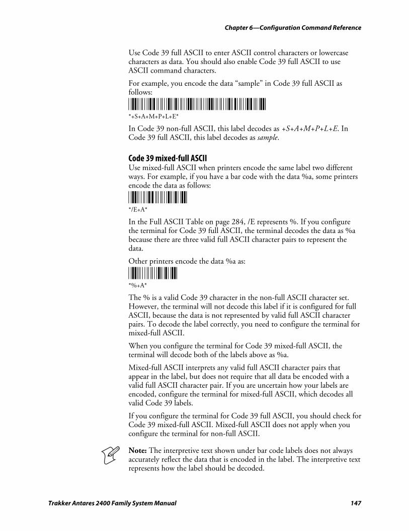
Chapter 6—Configuration Command Reference
Trakker Antares 2400 Family System Manual 147
Use Code 39 full ASCII to enter ASCII control characters or lowercase characters as data. You should also enable Code 39 full ASCII to use ASCII command characters.
For example, you encode the data “sample” in Code 39 full ASCII as follows:
*+S+A+M+P+L+E* *+S+A+M+P+L+E*
In Code 39 non-full ASCII, this label decodes as +S+A+M+P+L+E. In Code 39 full ASCII, this label decodes as sample.
Code 39 mixed-full ASCII Use mixed-full ASCII when printers encode the same label two different ways. For example, if you have a bar code with the data %a, some printers encode the data as follows:
*/E+A* */E+A*
In the Full ASCII Table on page 284, /E represents %. If you configure the terminal for Code 39 full ASCII, the terminal decodes the data as %a because there are three valid full ASCII character pairs to represent the data.
Other printers encode the data %a as:
*%+A* *%+A*
The % is a valid Code 39 character in the non-full ASCII character set. However, the terminal will not decode this label if it is configured for full ASCII, because the data is not represented by valid full ASCII character pairs. To decode the label correctly, you need to configure the terminal for mixed-full ASCII.
When you configure the terminal for Code 39 mixed-full ASCII, the terminal will decode both of the labels above as %a.
Mixed-full ASCII interprets any valid full ASCII character pairs that appear in the label, but does not require that all data be encoded with a valid full ASCII character pair. If you are uncertain how your labels are encoded, configure the terminal for mixed-full ASCII, which decodes all valid Code 39 labels.
If you configure the terminal for Code 39 full ASCII, you should check for Code 39 mixed-full ASCII. Mixed-full ASCII does not apply when you configure the terminal for non-full ASCII.
Note: The interpretive text shown under bar code labels does not always accurately reflect the data that is encoded in the label. The interpretive text represents how the label should be decoded.
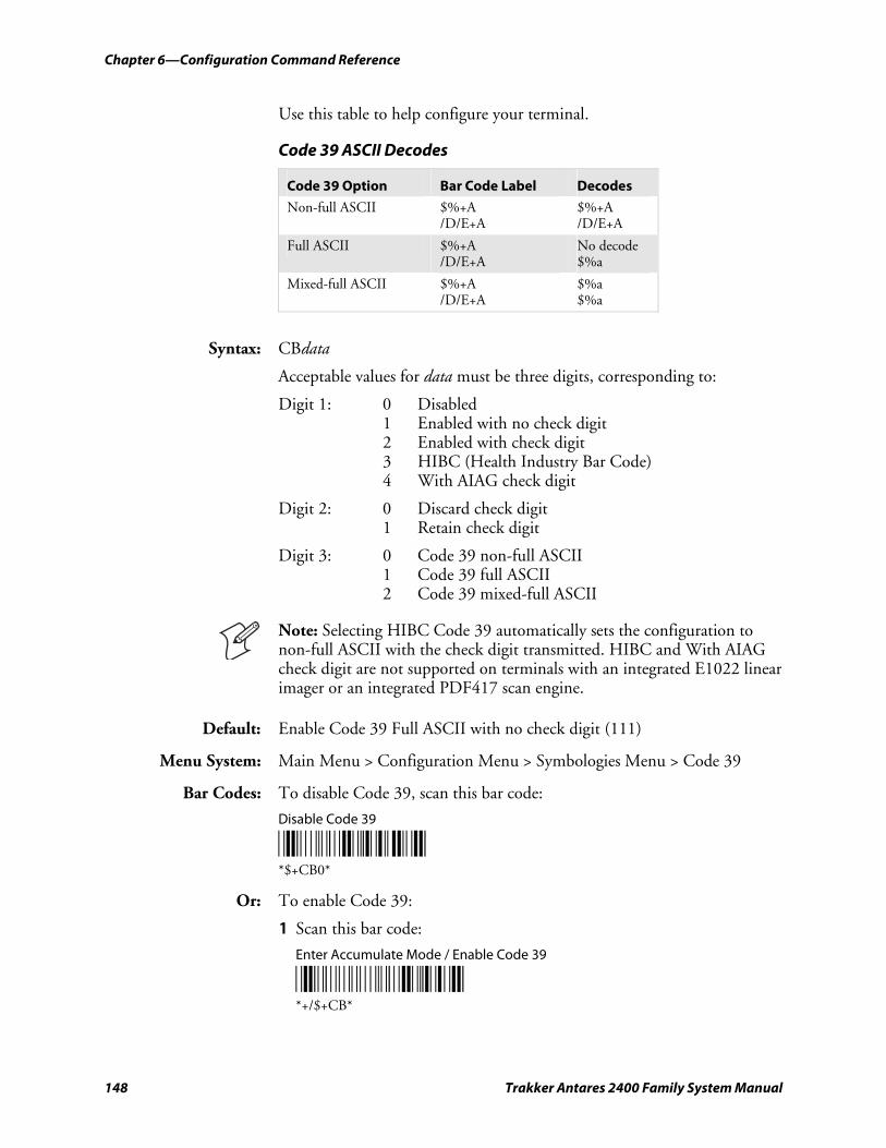
Chapter 6—Configuration Command Reference
148 Trakker Antares 2400 Family System Manual
Use this table to help configure your terminal.
Code 39 ASCII Decodes
Code 39 Option Bar Code Label Decodes
Non-full ASCII $%+A /D/E+A
$%+A /D/E+A
Full ASCII $%+A /D/E+A
No decode $%a
Mixed-full ASCII $%+A /D/E+A
$%a $%a
Syntax: CBdata
Acceptable values for data must be three digits, corresponding to:
Digit 1: 0 Disabled 1 Enabled with no check digit 2 Enabled with check digit 3 HIBC (Health Industry Bar Code) 4 With AIAG check digit
Digit 2: 0 Discard check digit 1 Retain check digit
Digit 3: 0 Code 39 non-full ASCII 1 Code 39 full ASCII 2 Code 39 mixed-full ASCII
Note: Selecting HIBC Code 39 automatically sets the configuration to non-full ASCII with the check digit transmitted. HIBC and With AIAG check digit are not supported on terminals with an integrated E1022 linear imager or an integrated PDF417 scan engine.
Default: Enable Code 39 Full ASCII with no check digit (111)
Menu System: Main Menu > Configuration Menu > Symbologies Menu > Code 39
Bar Codes: To disable Code 39, scan this bar code:
Disable Code 39
*$+CB0* *$+CB0*
Or: To enable Code 39:
1 Scan this bar code:
Enter Accumulate Mode / Enable Code 39
*+/$+CB* *+/$+CB*
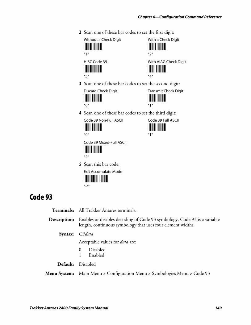
Chapter 6—Configuration Command Reference
Trakker Antares 2400 Family System Manual 149
2 Scan one of these bar codes to set the first digit:
Without a Check Digit With a Check Digit
*1* *2* *1* *2*
HIBC Code 39 With AIAG Check Digit
*3* *4* *3* *4*
3 Scan one of these bar codes to set the second digit:
Discard Check Digit Transmit Check Digit
*0* *1* *0* *1*
4 Scan one of these bar codes to set the third digit:
Code 39 Non-Full ASCII Code 39 Full ASCII
*0* *1* *0* *1*
Code 39 Mixed-Full ASCII
*2* *2*
5 Scan this bar code:
Exit Accumulate Mode
*-/* *-/*
Code 93
Terminals: All Trakker Antares terminals.
Description: Enables or disables decoding of Code 93 symbology. Code 93 is a variable length, continuous symbology that uses four element widths.
Syntax: CFdata
Acceptable values for data are:
0 Disabled 1 Enabled
Default: Disabled
Menu System: Main Menu > Configuration Menu > Symbologies Menu > Code 93
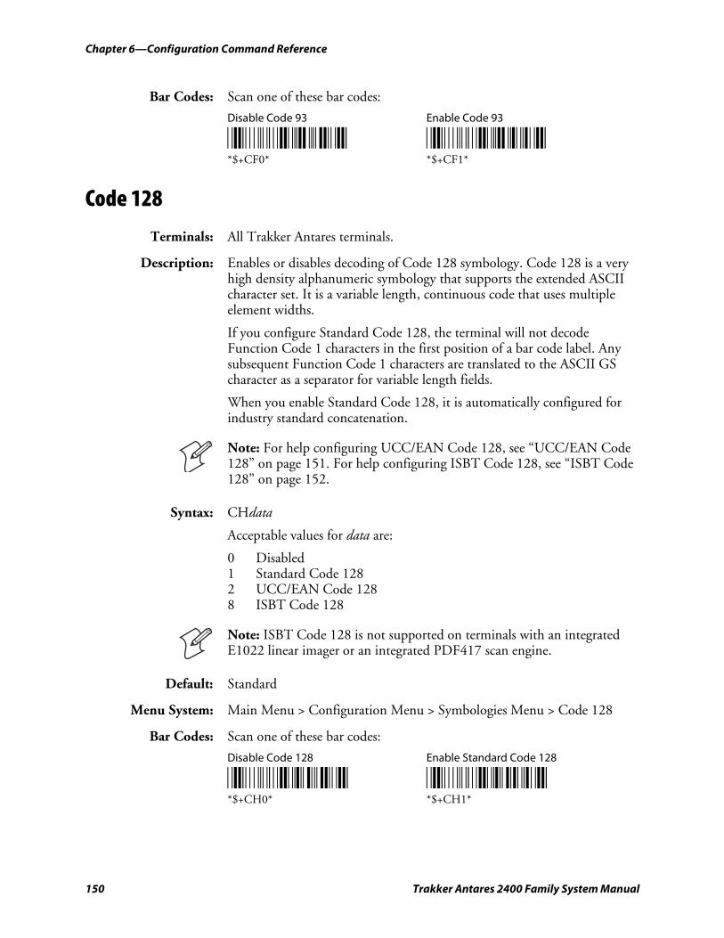
Chapter 6—Configuration Command Reference
150 Trakker Antares 2400 Family System Manual
Bar Codes: Scan one of these bar codes:
Disable Code 93 Enable Code 93
*$+CF0* *$+CF1* *$+CF0* *$+CF1*
Code 128
Terminals: All Trakker Antares terminals.
Description: Enables or disables decoding of Code 128 symbology. Code 128 is a very high density alphanumeric symbology that supports the extended ASCII character set. It is a variable length, continuous code that uses multiple element widths.
If you configure Standard Code 128, the terminal will not decode Function Code 1 characters in the first position of a bar code label. Any subsequent Function Code 1 characters are translated to the ASCII GS character as a separator for variable length fields.
When you enable Standard Code 128, it is automatically configured for industry standard concatenation.
Note: For help configuring UCC/EAN Code 128, see “UCC/EAN Code 128” on page 151. For help configuring ISBT Code 128, see “ISBT Code 128” on page 152.
Syntax: CHdata
Acceptable values for data are:
0 Disabled 1 Standard Code 128 2 UCC/EAN Code 128 8 ISBT Code 128
Note: ISBT Code 128 is not supported on terminals with an integrated E1022 linear imager or an integrated PDF417 scan engine.
Default: Standard
Menu System: Main Menu > Configuration Menu > Symbologies Menu > Code 128
Bar Codes: Scan one of these bar codes:
Disable Code 128 Enable Standard Code 128
*$+CH0* *$+CH1* *$+CH0* *$+CH1*
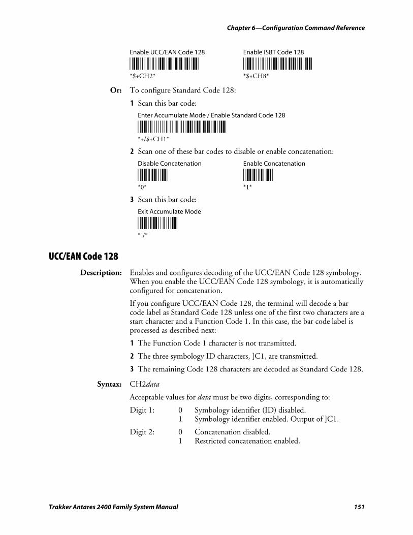
Chapter 6—Configuration Command Reference
Trakker Antares 2400 Family System Manual 151
Enable UCC/EAN Code 128 Enable ISBT Code 128
*$+CH2* *$+CH8* *$+CH2* *$+CH8*
Or: To configure Standard Code 128:
1 Scan this bar code:
Enter Accumulate Mode / Enable Standard Code 128
*+/$+CH1* *+/$+CH1*
2 Scan one of these bar codes to disable or enable concatenation:
Disable Concatenation Enable Concatenation
*0* *1* *0* *1*
3 Scan this bar code:
Exit Accumulate Mode
*-/* *-/*
UCC/EAN Code 128 Description: Enables and configures decoding of the UCC/EAN Code 128 symbology.
When you enable the UCC/EAN Code 128 symbology, it is automatically configured for concatenation.
If you configure UCC/EAN Code 128, the terminal will decode a bar code label as Standard Code 128 unless one of the first two characters are a start character and a Function Code 1. In this case, the bar code label is processed as described next:
1 The Function Code 1 character is not transmitted.
2 The three symbology ID characters, ]C1, are transmitted.
3 The remaining Code 128 characters are decoded as Standard Code 128.
Syntax: CH2data
Acceptable values for data must be two digits, corresponding to:
Digit 1: 0 Symbology identifier (ID) disabled. 1 Symbology identifier enabled. Output of ]C1.
Digit 2: 0 Concatenation disabled. 1 Restricted concatenation enabled.
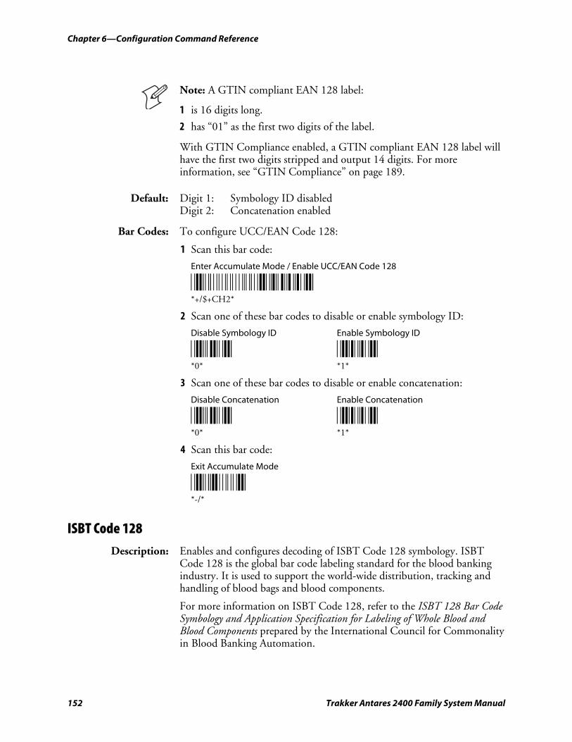
Chapter 6—Configuration Command Reference
152 Trakker Antares 2400 Family System Manual
Note: A GTIN compliant EAN 128 label:
1 is 16 digits long.
2 has “01” as the first two digits of the label.
With GTIN Compliance enabled, a GTIN compliant EAN 128 label will have the first two digits stripped and output 14 digits. For more information, see “GTIN Compliance” on page 189.
Default: Digit 1: Symbology ID disabled Digit 2: Concatenation enabled
Bar Codes: To configure UCC/EAN Code 128:
1 Scan this bar code:
Enter Accumulate Mode / Enable UCC/EAN Code 128
*+/$+CH2* *+/$+CH2*
2 Scan one of these bar codes to disable or enable symbology ID:
Disable Symbology ID Enable Symbology ID
*0* *1* *0* *1*
3 Scan one of these bar codes to disable or enable concatenation:
Disable Concatenation Enable Concatenation
*0* *1* *0* *1*
4 Scan this bar code:
Exit Accumulate Mode
*-/* *-/*
ISBT Code 128 Description: Enables and configures decoding of ISBT Code 128 symbology. ISBT
Code 128 is the global bar code labeling standard for the blood banking industry. It is used to support the world-wide distribution, tracking and handling of blood bags and blood components.
For more information on ISBT Code 128, refer to the ISBT 128 Bar Code Symbology and Application Specification for Labeling of Whole Blood and Blood Components prepared by the International Council for Commonality in Blood Banking Automation.
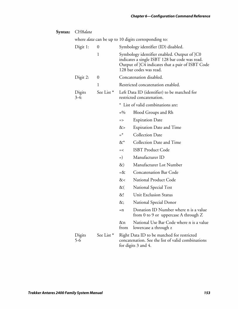
Chapter 6—Configuration Command Reference
Trakker Antares 2400 Family System Manual 153
Syntax: CH8data
where data can be up to 10 digits corresponding to:
Digit 1: 0 Symbology identifier (ID) disabled.
1 Symbology identifier enabled. Output of ]C0 indicates a single ISBT 128 bar code was read. Output of ]C4 indicates that a pair of ISBT Code 128 bar codes was read.
Digit 2: 0 Concatenation disabled.
1 Restricted concatenation enabled.
Digits 3-4:
See List * Left Data ID (identifier) to be matched for restricted concatenation.
* List of valid combinations are:
=% Blood Groups and Rh
=> Expiration Date
&> Expiration Date and Time
=* Collection Date
&* Collection Date and Time
=< ISBT Product Code
=) Manufacturer ID
&) Manufacturer Lot Number
=& Concatenation Bar Code
&< National Product Code
&( National Special Test
&! Unit Exclusion Status
&; National Special Donor
=n Donation ID Number where n is a value from 0 to 9 or uppercase A through Z
&n National Use Bar Code where n is a value from lowercase a through z
Digits 5-6
See List * Right Data ID to be matched for restricted concatenation. See the list of valid combinations for digits 3 and 4.
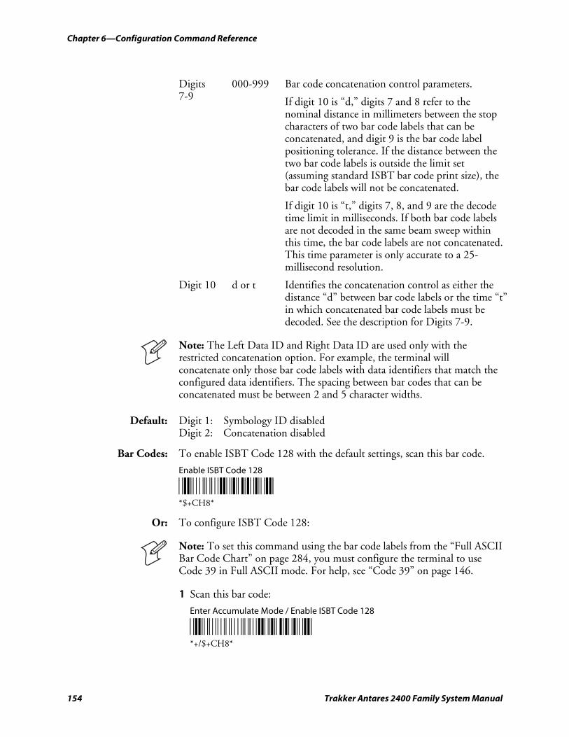
Chapter 6—Configuration Command Reference
154 Trakker Antares 2400 Family System Manual
Digits 7-9
000-999 Bar code concatenation control parameters.
If digit 10 is “d,” digits 7 and 8 refer to the nominal distance in millimeters between the stop characters of two bar code labels that can be concatenated, and digit 9 is the bar code label positioning tolerance. If the distance between the two bar code labels is outside the limit set (assuming standard ISBT bar code print size), the bar code labels will not be concatenated.
If digit 10 is “t,” digits 7, 8, and 9 are the decode time limit in milliseconds. If both bar code labels are not decoded in the same beam sweep within this time, the bar code labels are not concatenated. This time parameter is only accurate to a 25-millisecond resolution.
Digit 10 d or t Identifies the concatenation control as either the distance “d” between bar code labels or the time “t” in which concatenated bar code labels must be decoded. See the description for Digits 7-9.
Note: The Left Data ID and Right Data ID are used only with the restricted concatenation option. For example, the terminal will concatenate only those bar code labels with data identifiers that match the configured data identifiers. The spacing between bar codes that can be concatenated must be between 2 and 5 character widths.
Default: Digit 1: Symbology ID disabled Digit 2: Concatenation disabled
Bar Codes: To enable ISBT Code 128 with the default settings, scan this bar code.
Enable ISBT Code 128
*$+CH8* *$+CH8*
Or: To configure ISBT Code 128:
Note: To set this command using the bar code labels from the “Full ASCII Bar Code Chart” on page 284, you must configure the terminal to use Code 39 in Full ASCII mode. For help, see “Code 39” on page 146.
1 Scan this bar code:
Enter Accumulate Mode / Enable ISBT Code 128
*+/$+CH8* *+/$+CH8*
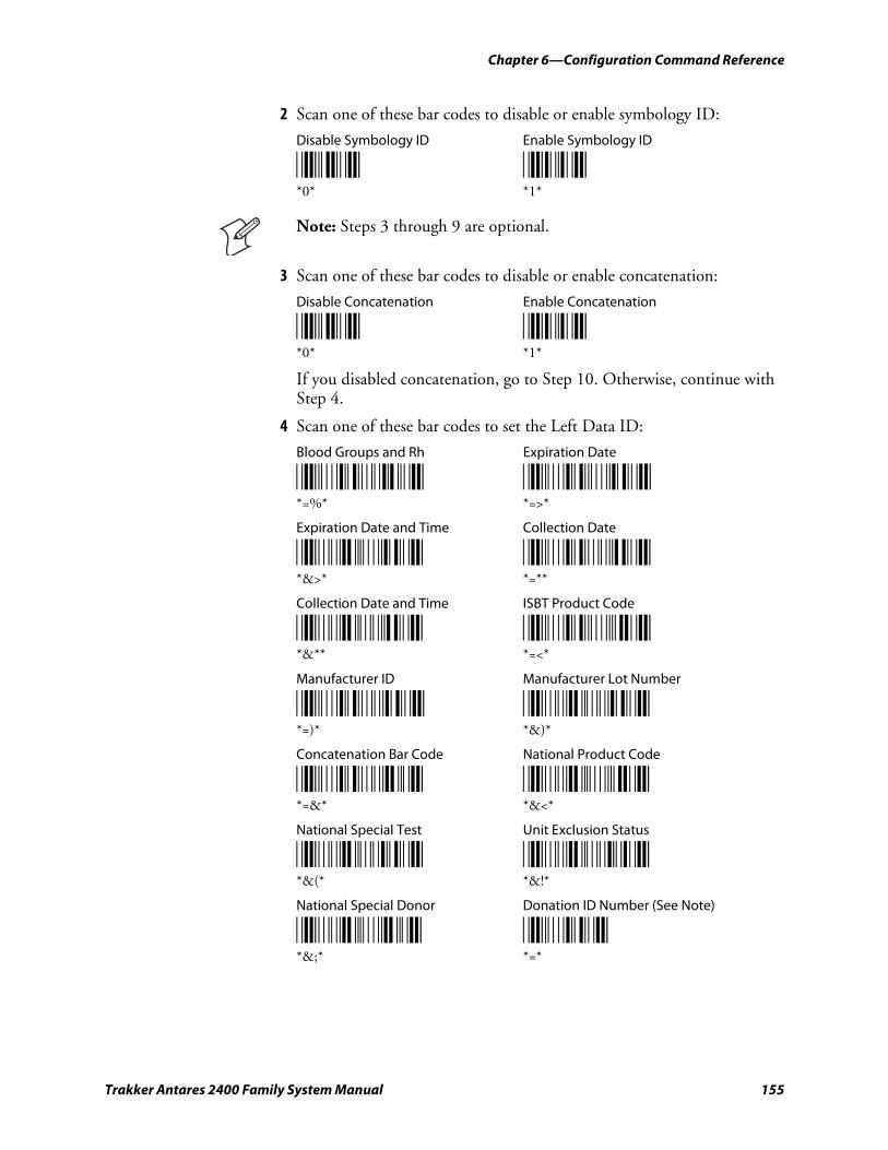
Chapter 6—Configuration Command Reference
Trakker Antares 2400 Family System Manual 155
2 Scan one of these bar codes to disable or enable symbology ID:
Disable Symbology ID Enable Symbology ID
*0* *1* *0* *1*
Note: Steps 3 through 9 are optional.
3 Scan one of these bar codes to disable or enable concatenation:
Disable Concatenation Enable Concatenation
*0* *1* *0* *1*
If you disabled concatenation, go to Step 10. Otherwise, continue with Step 4.
4 Scan one of these bar codes to set the Left Data ID:
Blood Groups and Rh Expiration Date
*%H/E* *%H%I* *=%* *=>*
Expiration Date and Time Collection Date
*/F%I* *%H/J* *&>* *=**
Collection Date and Time ISBT Product Code
*/F/J* *%H%G* *&** *=<*
Manufacturer ID Manufacturer Lot Number
*%H/I* */F/I* *=)* *&)*
Concatenation Bar Code National Product Code
*%H/F* */F%G* *=&* *&<*
National Special Test Unit Exclusion Status
*/F/H* */F/A* *&(* *&!*
National Special Donor Donation ID Number (See Note)
*/F%F* *%H* *&;* *=*
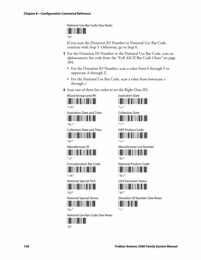
Chapter 6—Configuration Command Reference
156 Trakker Antares 2400 Family System Manual
National Use Bar Code (See Note)
*/F* *&*
If you scan the Donation ID Number or National Use Bar Code, continue with Step 5. Otherwise, go to Step 6.
5 For the Donation ID Number or the National Use Bar Code, scan an alphanumeric bar code from the “Full ASCII Bar Code Chart” on page 284.
• For the Donation ID Number, scan a value from 0 through 9 or uppercase A through Z.
• For the National Use Bar Code, scan a value from lowercase a through z.
6 Scan one of these bar codes to set the Right Data ID:
Blood Groups and Rh Expiration Date
*%H/E* *%H%I* *=%* *=>*
Expiration Date and Time Collection Date
*/F%I* *%H/J* *&>* *=**
Collection Date and Time ISBT Product Code
*/F/J* *%H%G* *&** *=<*
Manufacturer ID Manufacturer Lot Number
*%H/I* */F/I* *=)* *&)*
Concatenation Bar Code National Product Code
*%H/F* */F%G* *=&* *&<*
National Special Test Unit Exclusion Status
*/F/H* */F/A* *&(* *&!*
National Special Donor Donation ID Number (See Note)
*/F%F* *%H* *&;* *=*
National Use Bar Code (See Note)
*/F* *&*
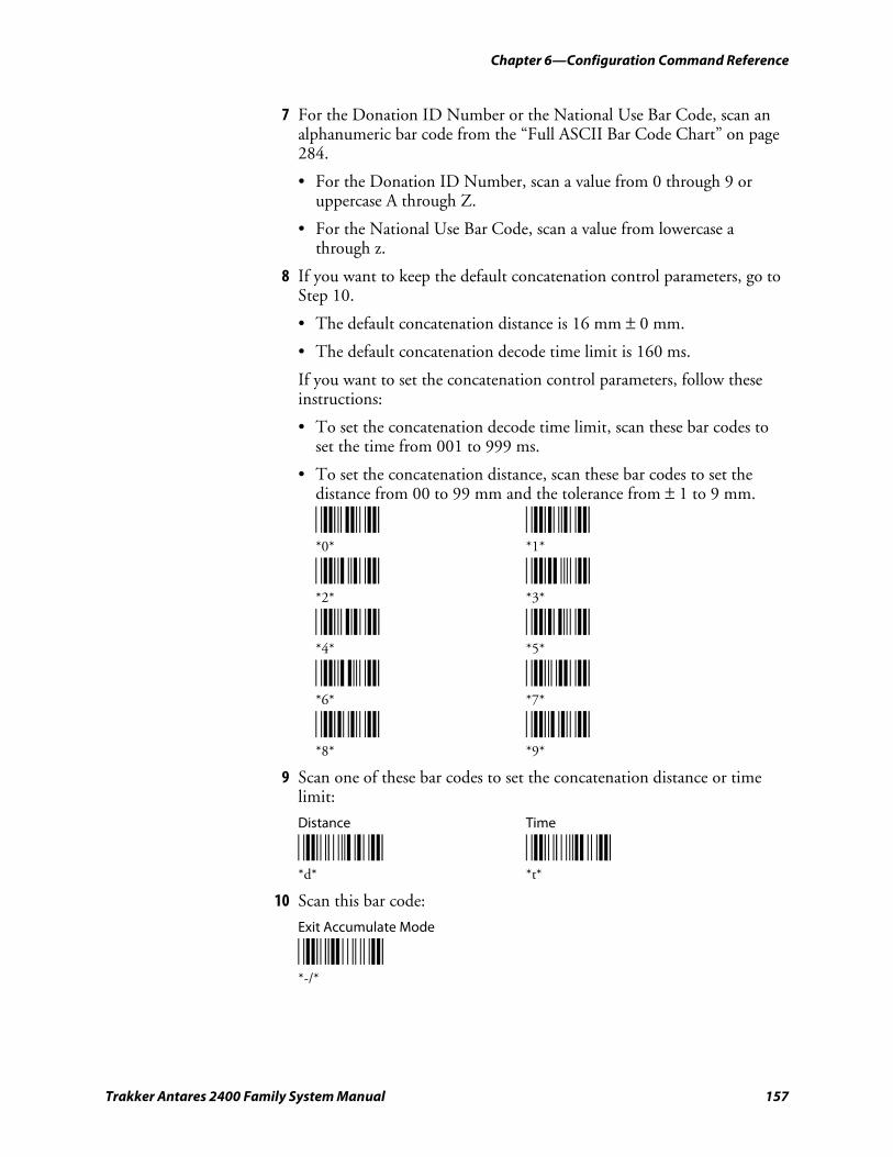
Chapter 6—Configuration Command Reference
Trakker Antares 2400 Family System Manual 157
7 For the Donation ID Number or the National Use Bar Code, scan an alphanumeric bar code from the “Full ASCII Bar Code Chart” on page 284.
• For the Donation ID Number, scan a value from 0 through 9 or uppercase A through Z.
• For the National Use Bar Code, scan a value from lowercase a through z.
8 If you want to keep the default concatenation control parameters, go to Step 10.
• The default concatenation distance is 16 mm ± 0 mm.
• The default concatenation decode time limit is 160 ms.
If you want to set the concatenation control parameters, follow these instructions:
• To set the concatenation decode time limit, scan these bar codes to set the time from 001 to 999 ms.
• To set the concatenation distance, scan these bar codes to set the distance from 00 to 99 mm and the tolerance from ± 1 to 9 mm.
*0* *1* *0* *1*
*2* *3* *2* *3*
*4* *5* *4* *5*
*6* *7* *6* *7*
*8* *9* *8* *9*
9 Scan one of these bar codes to set the concatenation distance or time limit:
Distance Time
*+D* *+T* *d* *t*
10 Scan this bar code:
Exit Accumulate Mode
*-/* *-/*
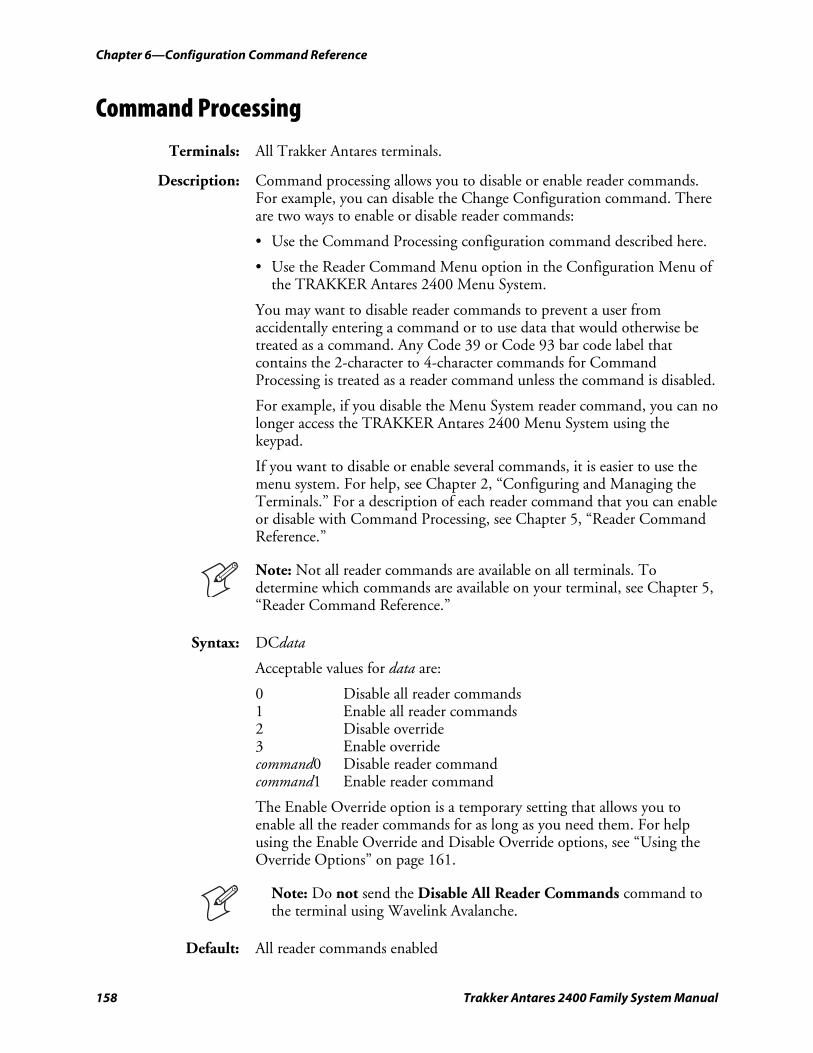
Chapter 6—Configuration Command Reference
158 Trakker Antares 2400 Family System Manual
Command Processing
Terminals: All Trakker Antares terminals.
Description: Command processing allows you to disable or enable reader commands. For example, you can disable the Change Configuration command. There are two ways to enable or disable reader commands:
• Use the Command Processing configuration command described here.
• Use the Reader Command Menu option in the Configuration Menu of the TRAKKER Antares 2400 Menu System.
You may want to disable reader commands to prevent a user from accidentally entering a command or to use data that would otherwise be treated as a command. Any Code 39 or Code 93 bar code label that contains the 2-character to 4-character commands for Command Processing is treated as a reader command unless the command is disabled.
For example, if you disable the Menu System reader command, you can no longer access the TRAKKER Antares 2400 Menu System using the keypad.
If you want to disable or enable several commands, it is easier to use the menu system. For help, see Chapter 2, “Configuring and Managing the Terminals.” For a description of each reader command that you can enable or disable with Command Processing, see Chapter 5, “Reader Command Reference.”
Note: Not all reader commands are available on all terminals. To determine which commands are available on your terminal, see Chapter 5, “Reader Command Reference.”
Syntax: DCdata
Acceptable values for data are:
0 Disable all reader commands 1 Enable all reader commands 2 Disable override 3 Enable override command0 Disable reader command command1 Enable reader command
The Enable Override option is a temporary setting that allows you to enable all the reader commands for as long as you need them. For help using the Enable Override and Disable Override options, see “Using the Override Options” on page 161.
Note: Do not send the Disable All Reader Commands command to the terminal using Wavelink Avalanche.
Default: All reader commands enabled
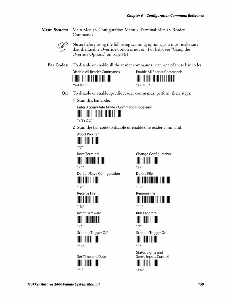
Chapter 6—Configuration Command Reference
Trakker Antares 2400 Family System Manual 159
Menu System: Main Menu > Configuration Menu > Terminal Menu > Reader Commands
Note: Before using the following scanning options, you must make sure that the Enable Override option is not on. For help, see “Using the Override Options” on page 161.
Bar Codes: To disable or enable all the reader commands, scan one of these bar codes:
Disable All Reader Commands Enable All Reader Commands
*$+DC0* *$+DC1* *$+DC0* *$+DC1*
Or: To disable or enable specific reader commands, perform these steps:
1 Scan this bar code:
Enter Accumulate Mode / Command Processing
*+/$+DC* *+/$+DC*
2 Scan the bar code to disable or enable one reader command.
Abort Program
*/$* */$*
Boot Terminal Change Configuration
*-.1* *$+* *-.1* *$+*
Default/Save Configuration Delete File
*.+* *..--* *.+* *..--*
Receive File Rename File
*.%* *...-* *.%* *...-*
Reset Firmware Run Program
*-.* *//* *-.* *//*
Scanner Trigger Off Scanner Trigger On
*/%* */.* */%* */.*
Status Lights and Set Time and Date Sense Inputs Control
*/+* *$%* */+* *$%*
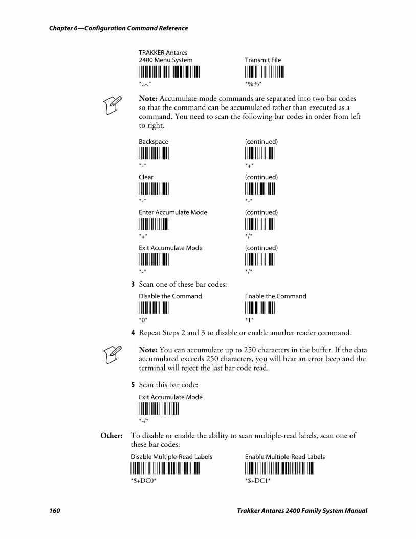
Chapter 6—Configuration Command Reference
160 Trakker Antares 2400 Family System Manual
TRAKKER Antares 2400 Menu System Transmit File
*..-.* *%%* *..-.* *%%*
Note: Accumulate mode commands are separated into two bar codes so that the command can be accumulated rather than executed as a command. You need to scan the following bar codes in order from left to right.
Backspace (continued)
*-* *+* *-* *+*
Clear (continued)
*-* *-* *-* *-*
Enter Accumulate Mode (continued)
*+* */* *+* */*
Exit Accumulate Mode (continued)
*-* */* *-* */*
3 Scan one of these bar codes:
Disable the Command Enable the Command
*0* *1* *0* *1*
4 Repeat Steps 2 and 3 to disable or enable another reader command.
Note: You can accumulate up to 250 characters in the buffer. If the data accumulated exceeds 250 characters, you will hear an error beep and the terminal will reject the last bar code read.
5 Scan this bar code:
Exit Accumulate Mode
*-/* *-/*
Other: To disable or enable the ability to scan multiple-read labels, scan one of these bar codes:
Disable Multiple-Read Labels Enable Multiple-Read Labels
*$+DC0* *$+DC1* *$+DC0* *$+DC1*
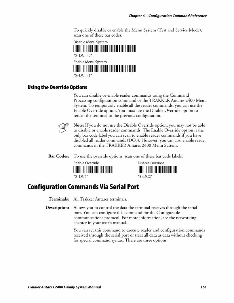
Chapter 6—Configuration Command Reference
Trakker Antares 2400 Family System Manual 161
To quickly disable or enable the Menu System (Test and Service Mode), scan one of these bar codes:
Disable Menu System
*$+DC..-.0* *$+DC..-.0*
Enable Menu System
*$+DC..-.1* *$+DC..-.1*
Using the Override Options You can disable or enable reader commands using the Command Processing configuration command or the TRAKKER Antares 2400 Menu System. To temporarily enable all the reader commands, you can use the Enable Override option. You must use the Disable Override option to return the terminal to the previous configuration.
Note: If you do not use the Disable Override option, you may not be able to disable or enable reader commands. The Enable Override option is the only bar code label you can scan to enable reader commands if you have disabled all reader commands (DC0). However, you can also enable reader commands in the TRAKKER Antares 2400 Menu System.
Bar Codes: To use the override options, scan one of these bar code labels:
Enable Override Disable Override
*$+DC3* *$+DC2* *$+DC3* *$+DC2*
Configuration Commands Via Serial Port
Terminals: All Trakker Antares terminals.
Description: Allows you to control the data the terminal receives through the serial port. You can configure this command for the Configurable communications protocol. For more information, see the networking chapter in your user’s manual.
You can set this command to execute reader and configuration commands received through the serial port or treat all data as data without checking for special command syntax. There are three options.
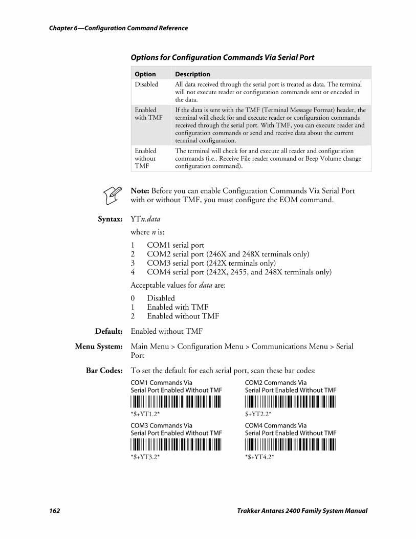
Chapter 6—Configuration Command Reference
162 Trakker Antares 2400 Family System Manual
Options for Configuration Commands Via Serial Port
Option Description
Disabled All data received through the serial port is treated as data. The terminal will not execute reader or configuration commands sent or encoded in the data.
Enabled with TMF
If the data is sent with the TMF (Terminal Message Format) header, the terminal will check for and execute reader or configuration commands received through the serial port. With TMF, you can execute reader and configuration commands or send and receive data about the current terminal configuration.
Enabled without TMF
The terminal will check for and execute all reader and configuration commands (i.e., Receive File reader command or Beep Volume change configuration command).
Note: Before you can enable Configuration Commands Via Serial Port with or without TMF, you must configure the EOM command.
Syntax: YTn.data
where n is:
1 COM1 serial port 2 COM2 serial port (246X and 248X terminals only) 3 COM3 serial port (242X terminals only) 4 COM4 serial port (242X, 2455, and 248X terminals only)
Acceptable values for data are:
0 Disabled 1 Enabled with TMF 2 Enabled without TMF
Default: Enabled without TMF
Menu System: Main Menu > Configuration Menu > Communications Menu > Serial Port
Bar Codes: To set the default for each serial port, scan these bar codes:
COM1 Commands Via COM2 Commands Via Serial Port Enabled Without TMF Serial Port Enabled Without TMF
*$+YT1.2* *$+YT2.2* *$+YT1.2* $+YT2.2*
COM3 Commands Via COM4 Commands Via Serial Port Enabled Without TMF Serial Port Enabled Without TMF
*$+YT3.2* *$+YT4.2* *$+YT3.2* *$+YT4.2*
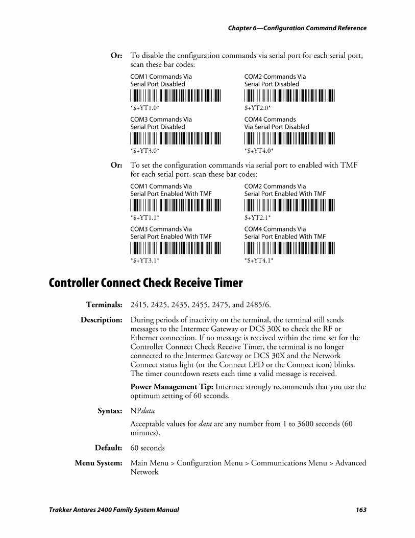
Chapter 6—Configuration Command Reference
Trakker Antares 2400 Family System Manual 163
Or: To disable the configuration commands via serial port for each serial port, scan these bar codes:
COM1 Commands Via COM2 Commands Via Serial Port Disabled Serial Port Disabled
*$+YT1.0* *$+YT2.0* *$+YT1.0* $+YT2.0*
COM3 Commands Via COM4 Commands Serial Port Disabled Via Serial Port Disabled
*$+YT3.0* *$+YT4.0* *$+YT3.0* *$+YT4.0*
Or: To set the configuration commands via serial port to enabled with TMF for each serial port, scan these bar codes:
COM1 Commands Via COM2 Commands Via Serial Port Enabled With TMF Serial Port Enabled With TMF
*$+YT1.1* *$+YT2.1* *$+YT1.1* $+YT2.1*
COM3 Commands Via COM4 Commands Via Serial Port Enabled With TMF Serial Port Enabled With TMF
*$+YT3.1* *$+YT4.1* *$+YT3.1* *$+YT4.1*
Controller Connect Check Receive Timer
Terminals: 2415, 2425, 2435, 2455, 2475, and 2485/6.
Description: During periods of inactivity on the terminal, the terminal still sends messages to the Intermec Gateway or DCS 30X to check the RF or Ethernet connection. If no message is received within the time set for the Controller Connect Check Receive Timer, the terminal is no longer connected to the Intermec Gateway or DCS 30X and the Network Connect status light (or the Connect LED or the Connect icon) blinks. The timer countdown resets each time a valid message is received.
Power Management Tip: Intermec strongly recommends that you use the optimum setting of 60 seconds.
Syntax: NPdata
Acceptable values for data are any number from 1 to 3600 seconds (60 minutes).
Default: 60 seconds
Menu System: Main Menu > Configuration Menu > Communications Menu > Advanced Network
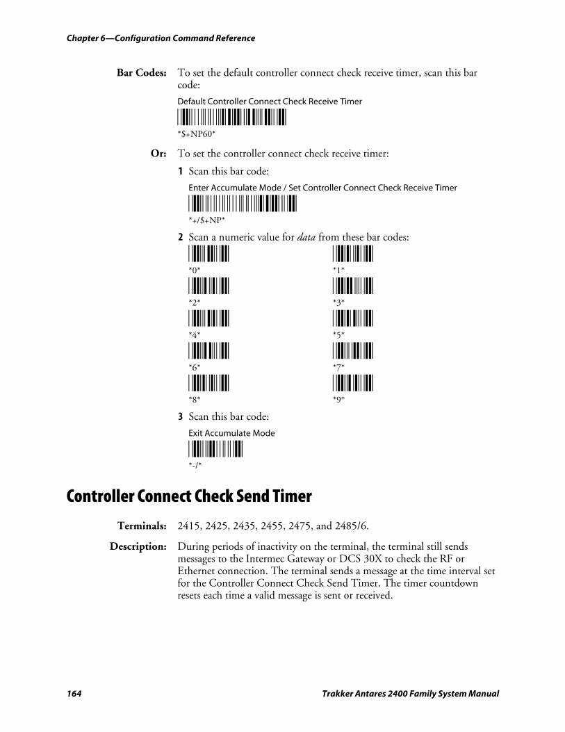
Chapter 6—Configuration Command Reference
164 Trakker Antares 2400 Family System Manual
Bar Codes: To set the default controller connect check receive timer, scan this bar code:
Default Controller Connect Check Receive Timer
*$+NP60* *$+NP60*
Or: To set the controller connect check receive timer:
1 Scan this bar code:
Enter Accumulate Mode / Set Controller Connect Check Receive Timer
*+/$+NP* *+/$+NP*
2 Scan a numeric value for data from these bar codes:
*0* *1* *0* *1*
*2* *3* *2* *3*
*4* *5* *4* *5*
*6* *7* *6* *7*
*8* *9* *8* *9*
3 Scan this bar code:
Exit Accumulate Mode
*-/* *-/*
Controller Connect Check Send Timer
Terminals: 2415, 2425, 2435, 2455, 2475, and 2485/6.
Description: During periods of inactivity on the terminal, the terminal still sends messages to the Intermec Gateway or DCS 30X to check the RF or Ethernet connection. The terminal sends a message at the time interval set for the Controller Connect Check Send Timer. The timer countdown resets each time a valid message is sent or received.
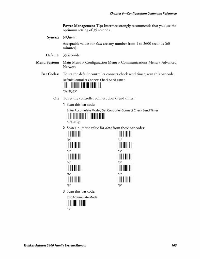
Chapter 6—Configuration Command Reference
Trakker Antares 2400 Family System Manual 165
Power Management Tip: Intermec strongly recommends that you use the optimum setting of 35 seconds.
Syntax: NQdata
Acceptable values for data are any number from 1 to 3600 seconds (60 minutes).
Default: 35 seconds
Menu System: Main Menu > Configuration Menu > Communications Menu > Advanced Network
Bar Codes: To set the default controller connect check send timer, scan this bar code:
Default Controller Connect Check Send Timer
*$+NQ35* *$+NQ35*
Or: To set the controller connect check send timer:
1 Scan this bar code:
Enter Accumulate Mode / Set Controller Connect Check Send Timer
*+/$+NQ* *+/$+NQ*
2 Scan a numeric value for data from these bar codes:
*0* *1* *0* *1*
*2* *3* *2* *3*
*4* *5* *4* *5*
*6* *7* *6* *7*
*8* *9* *8* *9*
3 Scan this bar code:
Exit Accumulate Mode
*-/* *-/*
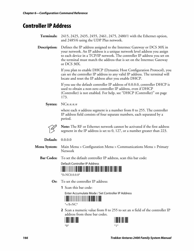
Chapter 6—Configuration Command Reference
166 Trakker Antares 2400 Family System Manual
Controller IP Address
Terminals: 2415, 2425, 2435, 2455, 2461, 2475, 2480/1 with the Ethernet option, and 2485/6 using the UDP Plus network.
Description: Defines the IP address assigned to the Intermec Gateway or DCS 30X in your network. An IP address is a unique network level address you assign to each device in a TCP/IP network. The controller IP address you set on the terminal must match the address that is set on the Intermec Gateway or DCS 30X.
If you plan to enable DHCP (Dynamic Host Configuration Protocol), you can set the controller IP address to any valid IP address. The terminal will locate and reset the IP address after you enable DHCP.
If you use the default controller IP address of 0.0.0.0, controller DHCP is used to obtain a non-zero controller IP address, even if DHCP (Controller) is not enabled. For help, see “DHCP (Controller)” on page 173.
Syntax: NCn.n.n.n
where each n address segment is a number from 0 to 255. The controller IP address field consists of four separate numbers, each separated by a period.
Note: The RF or Ethernet network cannot be activated if the first address segment in the IP address is set to 0, 127, or a number greater than 223.
Default: 0.0.0.0
Menu System: Main Menu > Configuration Menu > Communications Menu > Primary Network
Bar Codes: To set the default controller IP address, scan this bar code:
Default Controller IP Address
*$+NC0.0.0.0* *$+NC0.0.0.0*
Or: To set the controller IP address:
1 Scan this bar code:
Enter Accumulate Mode / Set Controller IP Address
*+/$+NC* *+/$+NC*
2 Scan a numeric value from 0 to 255 to set an n field of the controller IP address from these bar codes.
*0* *1* *0* *1*
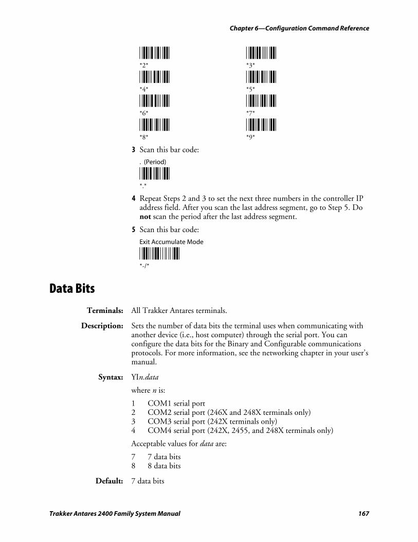
Chapter 6—Configuration Command Reference
Trakker Antares 2400 Family System Manual 167
*2* *3* *2* *3*
*4* *5* *4* *5*
*6* *7* *6* *7*
*8* *9* *8* *9*
3 Scan this bar code:
. (Period)
*.* *.*
4 Repeat Steps 2 and 3 to set the next three numbers in the controller IP address field. After you scan the last address segment, go to Step 5. Do not scan the period after the last address segment.
5 Scan this bar code:
Exit Accumulate Mode
*-/* *-/*
Data Bits
Terminals: All Trakker Antares terminals.
Description: Sets the number of data bits the terminal uses when communicating with another device (i.e., host computer) through the serial port. You can configure the data bits for the Binary and Configurable communications protocols. For more information, see the networking chapter in your user’s manual.
Syntax: YIn.data
where n is:
1 COM1 serial port 2 COM2 serial port (246X and 248X terminals only) 3 COM3 serial port (242X terminals only) 4 COM4 serial port (242X, 2455, and 248X terminals only)
Acceptable values for data are:
7 7 data bits 8 8 data bits
Default: 7 data bits
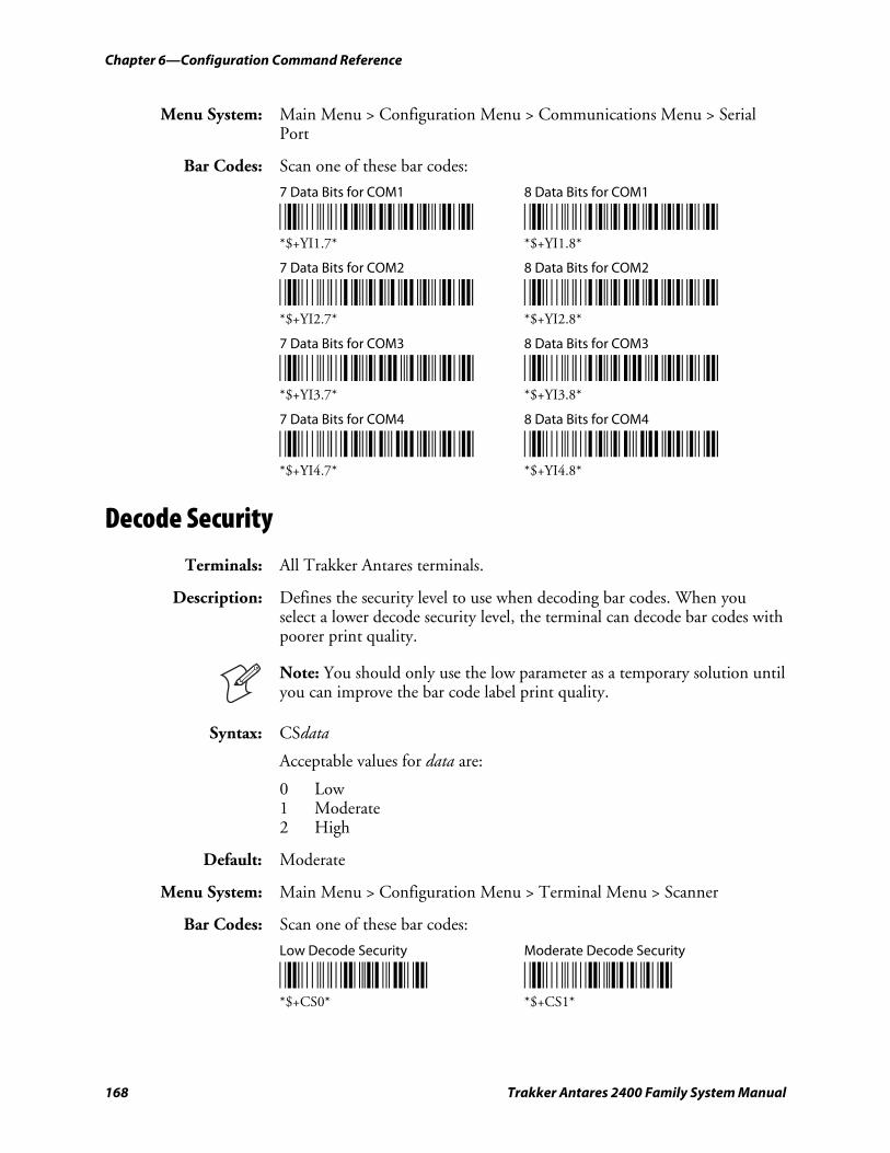
Chapter 6—Configuration Command Reference
168 Trakker Antares 2400 Family System Manual
Menu System: Main Menu > Configuration Menu > Communications Menu > Serial Port
Bar Codes: Scan one of these bar codes:
7 Data Bits for COM1 8 Data Bits for COM1
*$+YI1.7* *$+YI1.8* *$+YI1.7* *$+YI1.8*
7 Data Bits for COM2 8 Data Bits for COM2
*$+YI2.7* *$+YI2.8* *$+YI2.7* *$+YI2.8*
7 Data Bits for COM3 8 Data Bits for COM3
*$+YI3.7* *$+YI3.8* *$+YI3.7* *$+YI3.8*
7 Data Bits for COM4 8 Data Bits for COM4
*$+YI4.7* *$+YI4.8* *$+YI4.7* *$+YI4.8*
Decode Security
Terminals: All Trakker Antares terminals.
Description: Defines the security level to use when decoding bar codes. When you select a lower decode security level, the terminal can decode bar codes with poorer print quality.
Note: You should only use the low parameter as a temporary solution until you can improve the bar code label print quality.
Syntax: CSdata
Acceptable values for data are:
0 Low 1 Moderate 2 High
Default: Moderate
Menu System: Main Menu > Configuration Menu > Terminal Menu > Scanner
Bar Codes: Scan one of these bar codes:
Low Decode Security Moderate Decode Security
*$+CS0* *$+CS1* *$+CS0* *$+CS1*
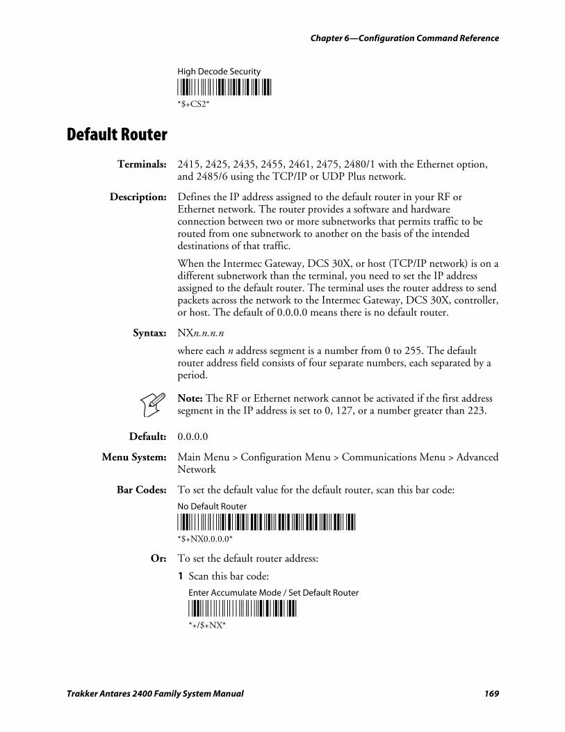
Chapter 6—Configuration Command Reference
Trakker Antares 2400 Family System Manual 169
High Decode Security
*$+CS2* *$+CS2*
Default Router
Terminals: 2415, 2425, 2435, 2455, 2461, 2475, 2480/1 with the Ethernet option, and 2485/6 using the TCP/IP or UDP Plus network.
Description: Defines the IP address assigned to the default router in your RF or Ethernet network. The router provides a software and hardware connection between two or more subnetworks that permits traffic to be routed from one subnetwork to another on the basis of the intended destinations of that traffic.
When the Intermec Gateway, DCS 30X, or host (TCP/IP network) is on a different subnetwork than the terminal, you need to set the IP address assigned to the default router. The terminal uses the router address to send packets across the network to the Intermec Gateway, DCS 30X, controller, or host. The default of 0.0.0.0 means there is no default router.
Syntax: NXn.n.n.n
where each n address segment is a number from 0 to 255. The default router address field consists of four separate numbers, each separated by a period.
Note: The RF or Ethernet network cannot be activated if the first address segment in the IP address is set to 0, 127, or a number greater than 223.
Default: 0.0.0.0
Menu System: Main Menu > Configuration Menu > Communications Menu > Advanced Network
Bar Codes: To set the default value for the default router, scan this bar code:
No Default Router
*$+NX0.0.0.0* *$+NX0.0.0.0*
Or: To set the default router address:
1 Scan this bar code:
Enter Accumulate Mode / Set Default Router
*+/$+NX* *+/$+NX*
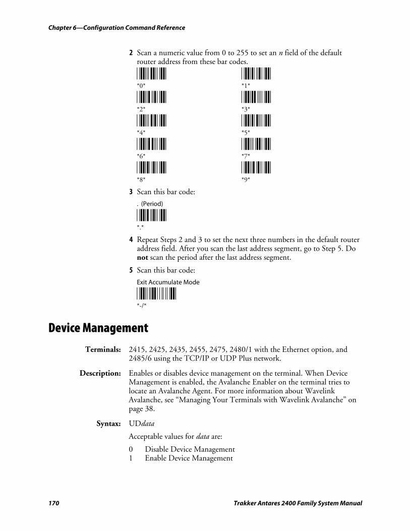
Chapter 6—Configuration Command Reference
170 Trakker Antares 2400 Family System Manual
2 Scan a numeric value from 0 to 255 to set an n field of the default router address from these bar codes.
*0* *1* *0* *1*
*2* *3* *2* *3*
*4* *5* *4* *5*
*6* *7* *6* *7*
*8* *9* *8* *9*
3 Scan this bar code:
. (Period)
*.* *.*
4 Repeat Steps 2 and 3 to set the next three numbers in the default router address field. After you scan the last address segment, go to Step 5. Do not scan the period after the last address segment.
5 Scan this bar code:
Exit Accumulate Mode
*-/* *-/*
Device Management
Terminals: 2415, 2425, 2435, 2455, 2475, 2480/1 with the Ethernet option, and 2485/6 using the TCP/IP or UDP Plus network.
Description: Enables or disables device management on the terminal. When Device Management is enabled, the Avalanche Enabler on the terminal tries to locate an Avalanche Agent. For more information about Wavelink Avalanche, see “Managing Your Terminals with Wavelink Avalanche” on page 38.
Syntax: UDdata
Acceptable values for data are:
0 Disable Device Management 1 Enable Device Management
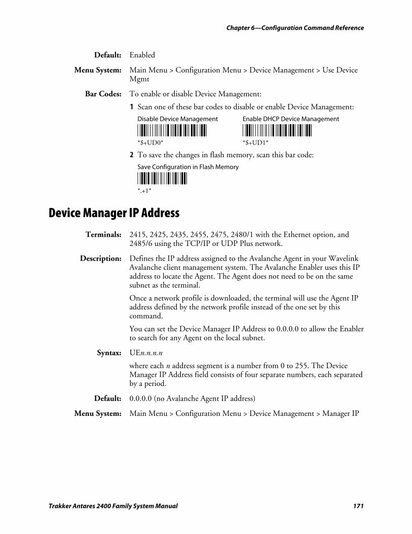
Chapter 6—Configuration Command Reference
Trakker Antares 2400 Family System Manual 171
Default: Enabled
Menu System: Main Menu > Configuration Menu > Device Management > Use Device Mgmt
Bar Codes: To enable or disable Device Management:
1 Scan one of these bar codes to disable or enable Device Management:
Disable Device Management Enable DHCP Device Management
*$+UD0* *$+UD1* *$+UD0* *$+UD1*
2 To save the changes in flash memory, scan this bar code:
Save Configuration in Flash Memory
*.+1* *.+1*
Device Manager IP Address
Terminals: 2415, 2425, 2435, 2455, 2475, 2480/1 with the Ethernet option, and 2485/6 using the TCP/IP or UDP Plus network.
Description: Defines the IP address assigned to the Avalanche Agent in your Wavelink Avalanche client management system. The Avalanche Enabler uses this IP address to locate the Agent. The Agent does not need to be on the same subnet as the terminal.
Once a network profile is downloaded, the terminal will use the Agent IP address defined by the network profile instead of the one set by this command.
You can set the Device Manager IP Address to 0.0.0.0 to allow the Enabler to search for any Agent on the local subnet.
Syntax: UEn.n.n.n
where each n address segment is a number from 0 to 255. The Device Manager IP Address field consists of four separate numbers, each separated by a period.
Default: 0.0.0.0 (no Avalanche Agent IP address)
Menu System: Main Menu > Configuration Menu > Device Management > Manager IP
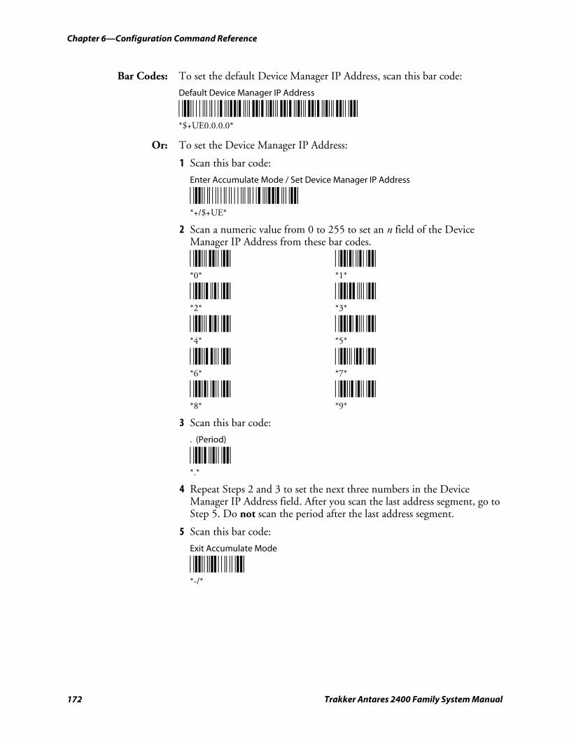
Chapter 6—Configuration Command Reference
172 Trakker Antares 2400 Family System Manual
Bar Codes: To set the default Device Manager IP Address, scan this bar code:
Default Device Manager IP Address
*$+UE0.0.0.0* *$+UE0.0.0.0*
Or: To set the Device Manager IP Address:
1 Scan this bar code:
Enter Accumulate Mode / Set Device Manager IP Address
*+/$+UE* *+/$+UE*
2 Scan a numeric value from 0 to 255 to set an n field of the Device Manager IP Address from these bar codes.
*0* *1* *0* *1*
*2* *3* *2* *3*
*4* *5* *4* *5*
*6* *7* *6* *7*
*8* *9* *8* *9*
3 Scan this bar code:
. (Period)
*.* *.*
4 Repeat Steps 2 and 3 to set the next three numbers in the Device Manager IP Address field. After you scan the last address segment, go to Step 5. Do not scan the period after the last address segment.
5 Scan this bar code:
Exit Accumulate Mode
*-/* *-/*
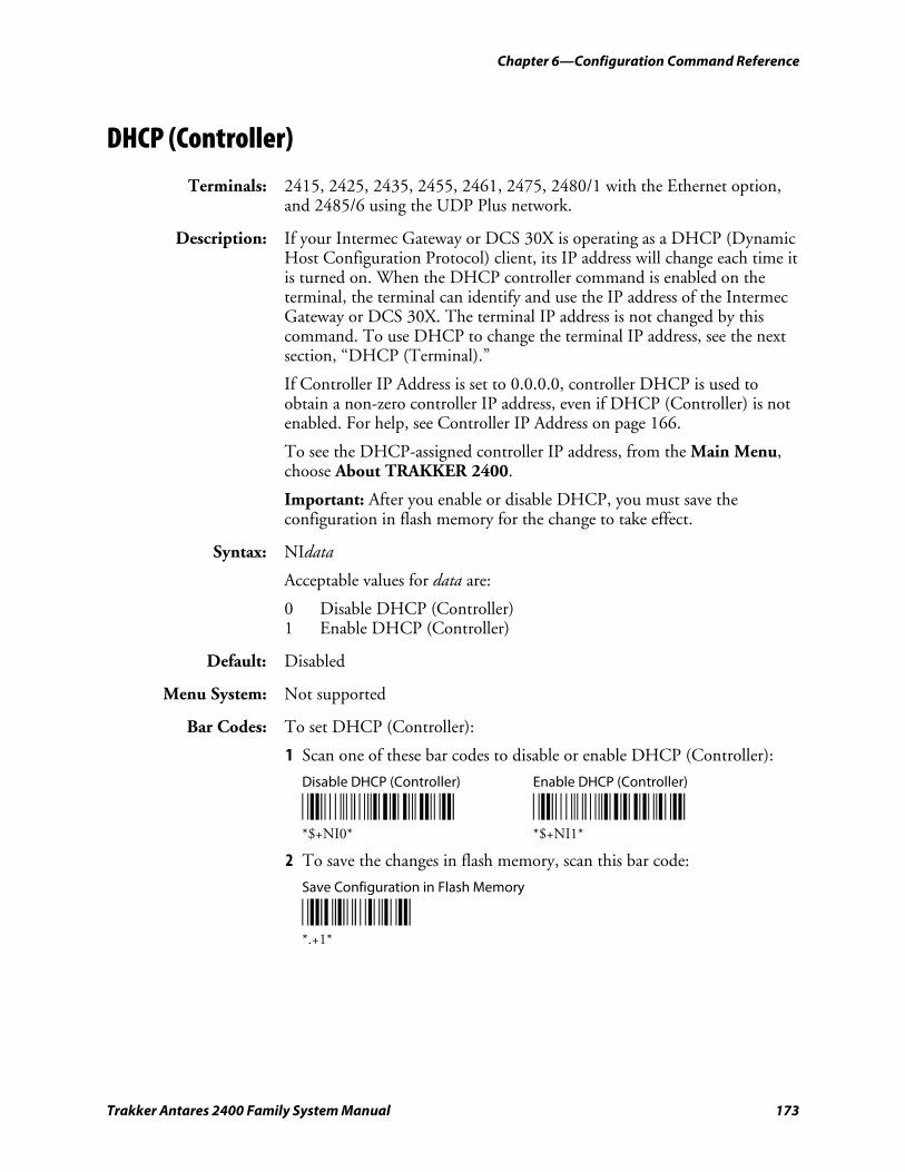
Chapter 6—Configuration Command Reference
Trakker Antares 2400 Family System Manual 173
DHCP (Controller)
Terminals: 2415, 2425, 2435, 2455, 2461, 2475, 2480/1 with the Ethernet option, and 2485/6 using the UDP Plus network.
Description: If your Intermec Gateway or DCS 30X is operating as a DHCP (Dynamic Host Configuration Protocol) client, its IP address will change each time it is turned on. When the DHCP controller command is enabled on the terminal, the terminal can identify and use the IP address of the Intermec Gateway or DCS 30X. The terminal IP address is not changed by this command. To use DHCP to change the terminal IP address, see the next section, “DHCP (Terminal).”
If Controller IP Address is set to 0.0.0.0, controller DHCP is used to obtain a non-zero controller IP address, even if DHCP (Controller) is not enabled. For help, see Controller IP Address on page 166.
To see the DHCP-assigned controller IP address, from the Main Menu, choose About TRAKKER 2400.
Important: After you enable or disable DHCP, you must save the configuration in flash memory for the change to take effect.
Syntax: NIdata
Acceptable values for data are:
0 Disable DHCP (Controller) 1 Enable DHCP (Controller)
Default: Disabled
Menu System: Not supported
Bar Codes: To set DHCP (Controller):
1 Scan one of these bar codes to disable or enable DHCP (Controller):
Disable DHCP (Controller) Enable DHCP (Controller)
*$+NI0* *$+NI1* *$+NI0* *$+NI1*
2 To save the changes in flash memory, scan this bar code:
Save Configuration in Flash Memory
*.+1* *.+1*
Chapter 6—Configuration Command Reference
174 Trakker Antares 2400 Family System Manual
DHCP (Terminal)
Terminals: 2415, 2425, 2435, 2455, 2461, 2475, 2480/1 with the Ethernet option, and 2485/6 using the TCP/IP or UDP Plus network.
Description: When DHCP (Dynamic Host Configuration Protocol) is enabled on the terminal, the terminal receives its IP address from the DHCP server. The IP address it receives may be permanent or leased.
DHCP Server Settings
Setting Description
Permanent The terminal uses the assigned IP address until you reboot the terminal.
Leased The terminal uses the assigned IP for leased amount of time that is specified by the server. The terminal must renew the lease before it expires to maintain communication.
Note: The leased DHCP server setting is not supported on the 2461.
The DHCP server assigns the following network parameters:
• Terminal IP Address
• Subnet Mask (optional)
• Default Router (optional)
The Terminal IP Address field displays 0.0.0.0 to indicate that DHCP is enabled, however, the terminal uses the IP address that it receives from the DHCP server. To see the IP address that the DHCP server assigns to the terminal, from the Main Menu, choose About TRAKKER 2400.
The parameters assigned by the DHCP server are not permanently stored on the terminal. These parameters are reset each time you reboot the terminal.
Syntax: Not supported.
Default: Enabled
Menu System: To use the menu system and enable the terminal to use DHCP:
1 From the Main Menu, choose Configuration Menu > Communications Menu > Primary Network.
2 Set the Terminal IP Address.
• To enable DHCP, set the Terminal IP Address to 0.0.0.0.
• To disable DHCP, set the Terminal IP Address to a value other than 0.0.0.0.
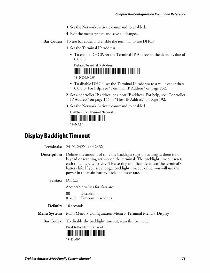
Chapter 6—Configuration Command Reference
Trakker Antares 2400 Family System Manual 175
3 Set the Network Activate command to enabled.
4 Exit the menu system and save all changes.
Bar Codes: To use bar codes and enable the terminal to use DHCP:
1 Set the Terminal IP Address.
• To enable DHCP, set the Terminal IP Address to the default value of 0.0.0.0.
Default Terminal IP Address
*$+ND0.0.0.0* *$+ND0.0.0.0*
• To disable DHCP, set the Terminal IP Address to a value other than 0.0.0.0. For help, see “Terminal IP Address” on page 252.
2 Set a controller IP address or a host IP address. For help, see “Controller IP Address” on page 166 or “Host IP Address” on page 192.
3 Set the Network Activate command to enabled.
Enable RF or Ethernet Network
*$+NA1* *$+NA1*
Display Backlight Timeout
Terminals: 241X, 242X, and 243X.
Description: Defines the amount of time the backlight stays on as long as there is no keypad or scanning activity on the terminal. The backlight timeout resets each time there is activity. This setting significantly affects the terminal’s battery life. If you set a longer backlight timeout value, you will use the power in the main battery pack at a faster rate.
Syntax: DFdata
Acceptable values for data are:
00 Disabled 01-60 Timeout in seconds
Default: 10 seconds
Menu System: Main Menu > Configuration Menu > Terminal Menu > Display
Bar Codes: To disable the backlight timeout, scan this bar code:
Disable Backlight Timeout
*$+DF00* *$+DF00*
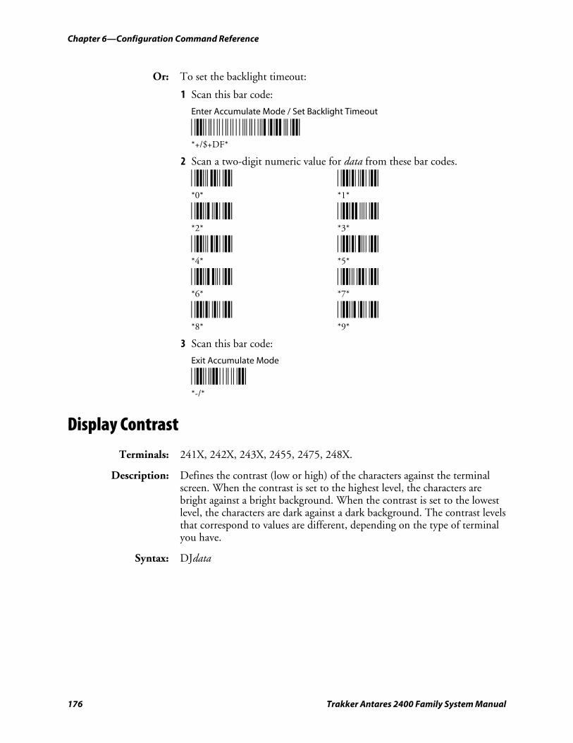
Chapter 6—Configuration Command Reference
176 Trakker Antares 2400 Family System Manual
Or: To set the backlight timeout:
1 Scan this bar code:
Enter Accumulate Mode / Set Backlight Timeout
*+/$+DF* *+/$+DF*
2 Scan a two-digit numeric value for data from these bar codes.
*0* *1* *0* *1*
*2* *3* *2* *3*
*4* *5* *4* *5*
*6* *7* *6* *7*
*8* *9* *8* *9*
3 Scan this bar code:
Exit Accumulate Mode
*-/* *-/*
Display Contrast
Terminals: 241X, 242X, 243X, 2455, 2475, 248X.
Description: Defines the contrast (low or high) of the characters against the terminal screen. When the contrast is set to the highest level, the characters are bright against a bright background. When the contrast is set to the lowest level, the characters are dark against a dark background. The contrast levels that correspond to values are different, depending on the type of terminal you have.
Syntax: DJdata
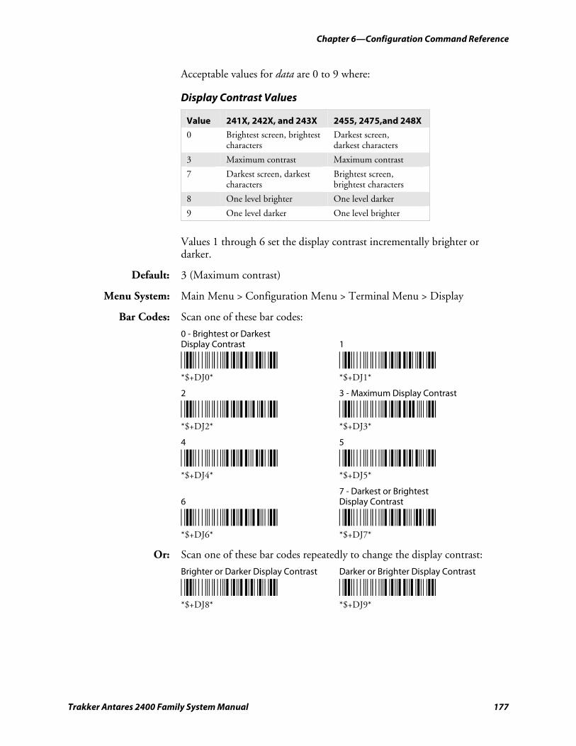
Chapter 6—Configuration Command Reference
Trakker Antares 2400 Family System Manual 177
Acceptable values for data are 0 to 9 where:
Display Contrast Values
Value 241X, 242X, and 243X 2455, 2475,and 248X
0 Brightest screen, brightest characters
Darkest screen, darkest characters
3 Maximum contrast Maximum contrast
7 Darkest screen, darkest characters
Brightest screen, brightest characters
8 One level brighter One level darker
9 One level darker One level brighter
Values 1 through 6 set the display contrast incrementally brighter or darker.
Default: 3 (Maximum contrast)
Menu System: Main Menu > Configuration Menu > Terminal Menu > Display
Bar Codes: Scan one of these bar codes:
0 - Brightest or Darkest Display Contrast 1
*$+DJ0* *$+DJ1* *$+DJ0* *$+DJ1*
2 3 - Maximum Display Contrast
*$+DJ2* *$+DJ3* *$+DJ2* *$+DJ3*
4 5
*$+DJ4* *$+DJ5* *$+DJ4* *$+DJ5*
7 - Darkest or Brightest 6 Display Contrast
*$+DJ6* *$+DJ7* *$+DJ6* *$+DJ7*
Or: Scan one of these bar codes repeatedly to change the display contrast:
Brighter or Darker Display Contrast Darker or Brighter Display Contrast
*$+DJ8* *$+DJ9* *$+DJ8* *$+DJ9*
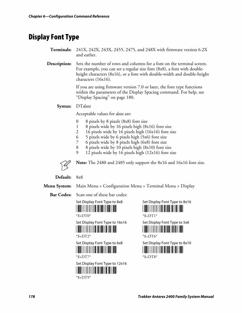
Chapter 6—Configuration Command Reference
178 Trakker Antares 2400 Family System Manual
Display Font Type
Terminals: 241X, 242X, 243X, 2455, 2475, and 248X with firmware version 6.2X and earlier.
Description: Sets the number of rows and columns for a font on the terminal screen. For example, you can set a regular size font (8x8), a font with double-height characters (8x16), or a font with double-width and double-height characters (16x16).
If you are using firmware version 7.0 or later, the font type functions within the parameters of the Display Spacing command. For help, see “Display Spacing” on page 180.
Syntax: DTdata
Acceptable values for data are:
0 8 pixels by 8 pixels (8x8) font size 1 8 pixels wide by 16 pixels high (8x16) font size 2 16 pixels wide by 16 pixels high (16x16) font size 6 5 pixels wide by 6 pixels high (5x6) font size 7 6 pixels wide by 8 pixels high (6x8) font size 8 8 pixels wide by 10 pixels high (8x10) font size 9 12 pixels wide by 16 pixels high (12x16) font size
Note: The 2480 and 2485 only support the 8x16 and 16x16 font size.
Default: 8x8
Menu System: Main Menu > Configuration Menu > Terminal Menu > Display
Bar Codes: Scan one of these bar codes:
Set Display Font Type to 8x8 Set Display Font Type to 8x16
*$+DT0* *$+DT1* *$+DT0* *$+DT1*
Set Display Font Type to 16x16 Set Display Font Type to 5x6
*$+DT2* *$+DT6* *$+DT2* *$+DT6*
Set Display Font Type to 6x8 Set Display Font Type to 8x10
*$+DT7* *$+DT8* *$+DT7* *$+DT8*
Set Display Font Type to 12x16
*$+DT9* *$+DT9*
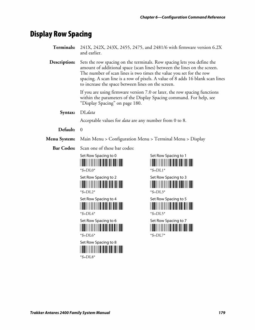
Chapter 6—Configuration Command Reference
Trakker Antares 2400 Family System Manual 179
Display Row Spacing
Terminals: 241X, 242X, 243X, 2455, 2475, and 2481/6 with firmware version 6.2X and earlier.
Description: Sets the row spacing on the terminals. Row spacing lets you define the amount of additional space (scan lines) between the lines on the screen. The number of scan lines is two times the value you set for the row spacing. A scan line is a row of pixels. A value of 8 adds 16 blank scan lines to increase the space between lines on the screen.
If you are using firmware version 7.0 or later, the row spacing functions within the parameters of the Display Spacing command. For help, see “Display Spacing” on page 180.
Syntax: DLdata
Acceptable values for data are any number from 0 to 8.
Default: 0
Menu System: Main Menu > Configuration Menu > Terminal Menu > Display
Bar Codes: Scan one of these bar codes:
Set Row Spacing to 0 Set Row Spacing to 1
*$+DL0* *$+DL1* *$+DL0* *$+DL1*
Set Row Spacing to 2 Set Row Spacing to 3
*$+DL2* *$+DL3* *$+DL2* *$+DL3*
Set Row Spacing to 4 Set Row Spacing to 5
*$+DL4* *$+DL5* *$+DL4* *$+DL5*
Set Row Spacing to 6 Set Row Spacing to 7
*$+DL6* *$+DL7* *$+DL6* *$+DL7*
Set Row Spacing to 8
*$+DL8* *$+DL8*
Chapter 6—Configuration Command Reference
180 Trakker Antares 2400 Family System Manual
Display Spacing
Terminals: 241X, 242X, 243X, 2455, 2475, and 2481/6.
Description: Defines the font size and spacing between each row and column on the terminal screen. You specify column and row spacing between font characters in numbers of pixel columns or pixel rows to be added between the font characters.
To define the Display Spacing command, you set three parameters: font type, column spacing, and row spacing. The font type parameter is one character while the column spacing and row spacing parameters are two characters each.
Note: The row spacing parameter used in this command adds the number of pixel rows that you set for the parameter. The row spacing parameter in the Display Row Spacing command (firmware version 6.23 and earlier) adds two times the number of pixel rows that you set for the parameter.
Use the following guidelines to determine how to set the optimal display spacing based on operator preference and operating environment:
• Font arrays already have one or two lines of spacing built in for character separation.
• The font type parameter determines the maximum size of each individual font character.
• Larger font types generate larger spacing values yielding fewer characters per row and fewer rows on the display.
Note: If the status icons are enabled on the 243X, it uses one column of five pixels to display the status icons. Therefore, the 243X yields one less column of characters than the indicated number of columns. For help enabling or disabling the 243X status icons, see “Display Video Mode” on page 182.
Syntax: DKdata
where data must be 5 digits selected from this list:
Digit 1: Acceptable values for Digit 1 are:
0 8 pixels by 8 pixels (8x8) font size 1 8 pixels wide by 16 pixels high (8x16) font size 2 16 pixels wide by 16 pixels high (16x16) font size 6 5 pixels wide by 6 pixels high (5x6) font size 7 6 pixels wide by 8 pixels high (6x8) font size 8 8 pixels wide by 10 pixels high (8x10) font size 9 12 pixels wide by 16 pixels high (12x16) font size
Chapter 6—Configuration Command Reference
Trakker Antares 2400 Family System Manual 181
B 5 pixels wide by 8 pixels high (5x8) font size C 12 pixels wide by 12 pixels high (12x12) font size
Digits 2-3: Any two-digit column spacing value from 00 to 15.
Digits 4-5: Any two-digit row spacing value from 00 to 24.
Default: 00000 (8x8 font size, no column spacing, no row spacing)
Menu System: Main Menu > Configuration Menu > Terminal Menu > Display
Note: When you change the display spacing, the terminal clears the screen of all data. Make sure all of your data is saved before changing the display spacing.
Bar Codes: To set the default value for the display spacing, scan this bar code:
8x8 font size, 20 columns x 16 rows
*$+DK00000* *$+DK00000*
Or: To set the standard spacing for a particular font type, scan one of these bar codes:
8x16 font size, 20 columns x 8 rows
*$+DK10000* *$+DK10000*
16x16 font size, 10 columns x 8 rows
*$+DK20000* *$+DK20000*
12x16 font size, 12 columns x 8 rows
*$+DK90100* *$+DK90100*
8x10 font size, 17 columns x 12 rows
*$+DK80100* *$+DK80100*
6x8 font size, 26 columns x 16 rows
*$+DK70000* *$+DK70000*
5x6 font size, 32 columns x 21 rows
*$+DK60000* *$+DK60000*
5x8 font size
*$+DKB0000* *$+DKB0000*
Chapter 6—Configuration Command Reference
182 Trakker Antares 2400 Family System Manual
12x12 font size
*$+DKC0000* *$+DKC0000*
Or: To set the display spacing:
1 Scan this bar code:
Enter Accumulate Mode / Set Display Spacing
*+/$+DK* *+/$+DK*
2 Scan a five-digit numeric value for data from these bar codes.
*0* *1* *0* *1*
*2* *3* *2* *3*
*4* *5* *4* *5*
*6* *7* *6* *7*
*8* *9* *8* *9*
3 Scan this bar code:
Exit Accumulate Mode
*-/* *-/*
Display Video Mode
Terminals: 241X, 242X, 243X, 2455, 2475, and 248X.
Description: Sets the display video mode that is used on the terminal screen. You can set the display video mode to original, normal, or inverse. The default is original and displays dark characters on a light background. Normal mode displays the darkest possible characters on the lightest possible background. Inverse mode displays the lightest possible characters on the darkest possible background.
If you have a 243X terminal, you can also use this command to display the status icons on the right side of the screen. Normal/Icon (Nrm/Icon) mode displays the icons in normal display video mode, and Inverse/Icon (Inv/Icon) mode displays the icons in inverse display video mode. For help using the 243X status icons, see the Trakker Antares 243X Handheld Terminal User’s Manual (P/N 071791).
Chapter 6—Configuration Command Reference
Trakker Antares 2400 Family System Manual 183
Syntax: DNdata
Acceptable values for data are:
0 Original 1 Normal 2 Inverse 3 Nrm/Icon (243X only) 4 Inv/Icon (243X only)
Default: 0 (Original)
Menu System: Main Menu > Configuration Menu > Terminal Menu > Display
Bar Codes: Scan one of these bar codes:
Original Display Video Mode Normal Display Video Mode
*$+DN0* *$+DN1* *$+DN0* *$+DN1*
Inverse Display Video Mode Normal Display Video Mode with Icons
*$+DN2* *$+DN3* *$+DN2* *$+DN3*
Inverse Display Video Mode with Icons
*$+DN4* *$+DN4*
Domain
Terminals: 2415, 2425, 2435, 2455, 2475, and 2485/6 with OpenAir radios.
Description: Defines a logical partition or subnetwork of the RF network. To establish communications, you must assign the same domain number to every RF device in the subnetwork. You can roam between access points as long as all the RF devices have the same domain number. You can also assign different domain numbers if you want to establish different RF subnetworks in the same area.
Syntax: RWdata
Acceptable values for data are any number from 0 to 15.
Default: 0
Menu System: Main Menu > Configuration Menu > Communications Menu > Radio
Bar Codes: To set the default domain, scan this bar code:
Default Domain
*$+RW0* *$+RW0*
Chapter 6—Configuration Command Reference
184 Trakker Antares 2400 Family System Manual
Or: To set a value for Domain:
1 Scan this bar code:
Enter Accumulate Mode / Set Domain
*+/$+RW* *+/$+RW*
2 Scan a numeric value for data from these bar codes:
*0* *1* *0* *1*
*2* *3* *2* *3*
*4* *5* *4* *5*
*6* *7* *6* *7*
*8* *9* *8* *9*
3 Scan this bar code:
Exit Accumulate Mode
*-/* *-/*
End of Message (EOM)
Terminals: All Trakker Antares terminals.
Description: Attaches an EOM to the end of a data block to indicate the end of data transmission to and from a terminal. When EOM is disabled, the terminal communicates in Character mode. When EOM is enabled, the terminal communicates in Frame mode. You can configure EOM for the Configurable communications protocol. For more information, see the networking chapter in your user’s manual.
You can set EOM to use characters from the extended ASCII character set using the TRAKKER Antares 2400 Menu System. This procedure is similar to the one for setting the preamble and postamble. For help, see “Entering ASCII Control Characters” in the configuration chapter in your user’s manual.
You must configure a value for EOM before you can set these other serial communications commands:
• Configuration Commands Via Serial Port
• Handshake
Chapter 6—Configuration Command Reference
Trakker Antares 2400 Family System Manual 185
• LRC
• Start of Message (SOM)
Note: EOM cannot equal the same value as SOM, and EOM1 cannot equal the same value as EOM2.
EOM cannot be set to these values:
• AFF (ACK) • REQ (ENQ)
• DLE • SEL
• NEG (NAK) • XOFF
• Poll • XON
• RES (EOT)
Syntax: YZn.data
where n is:
1 COM1 serial port 2 COM2 serial port (246X and 248X terminals only) 3 COM3 serial port (242X terminals only) 4 COM4 serial port (242X, 2455, and 248X terminals only)
Acceptable values for data are one or two ASCII characters.
Default: \x03 (hexadecimal value for ETX)
Menu System: Main Menu > Configuration Menu > Communications Menu > Serial Port
Bar Codes: To disable EOM for each serial port, scan these bar codes:
Disable EOM for COM1 Disable EOM for COM2
*$+YZ1.* *$+YZ2.* *$+YZ1.* *$+YZ2.*
Disable EOM for COM3 Disable EOM for COM4
*$+YZ3.* *$+YZ4.* *$+YZ3.* *$+YZ4.*
Or: To set EOM to one or two ASCII characters for one serial port:
Note: To set this command using the bar code labels from the “Full ASCII Bar Code Chart” on page 284, you must configure the terminal to use Code 39 in Full ASCII mode. For help, see “Code 39” on page 146.
1 Scan this bar code:
Enter Accumulate Mode / Set EOM
*/K/O/D/KYZ* *+/$+YZ*
Chapter 6—Configuration Command Reference
186 Trakker Antares 2400 Family System Manual
2 Scan the serial port from these bar codes:
COM1 COM2
*1/N* *2/N* *1.* *2.*
COM3 COM4
*3/N* *4/N* *3.* *4.*
3 Scan one or two bar codes for data from the “Full ASCII Bar Code Chart” on page 284.
4 Scan this bar code:
Exit Accumulate Mode
*/M/O* *-/*
5 Repeat Steps 2 through 4 to set EOM for another serial port.
Flash Memory Configuration
Terminals: All Trakker Antares terminals.
Description: Configures the use of the optional 2MB extended flash memory. If you have a terminal with the 4MB flash memory option, you can either configure the extra 2MB of flash memory as a drive D, or you can use it to store double-byte fonts. You cannot use the space for both. If you configure the flash memory as drive D, use this drive to store large lookup tables and data files. You can store up to 128 files on drive D or store up to 2MB of double-byte fonts.
After you configure the flash memory, you must save the configuration in flash memory and boot the terminal for the change to take effect.
Note: The 4MB flash memory is required for 802.1x TTLS security. If you have the 802.1x TTLS security option, you cannot configure Flash Memory Configuration. For more information about configuring 802.1x TTLS security, see “Configuring 802.1x TTLS Security” in the networking chapter of your user’s manual.
Syntax: FFdata
Acceptable values for data are:
0 Configure flash memory for double-byte fonts 32 Configure flash memory as the 2MB drive D
Default: 0 (Configure flash memory for double-byte fonts)
Menu System: Not supported
Chapter 6—Configuration Command Reference
Trakker Antares 2400 Family System Manual 187
Bar Codes: To set Flash Memory Configuration:
1 Scan one of these bar codes to configure flash memory:
Configure Flash Memory For Double-Byte Fonts Configure Flash Memory as Drive D
*$+FF0* *$+FF32* *$+FF0* *$+FF32*
2 To save the changes in flash memory, scan this bar code:
Save Configuration in Flash Memory
*.+1* *.+1*
3 Scan this bar code to boot the terminal and use the 2MB flash memory to store double-byte fonts or as drive D:
Reset Firmware
*-.* *-.*
Note: When you boot or reset the terminal, any fonts or files in flash memory on drive D are erased.
4 If you configured flash memory to store double-byte fonts, use the Trakker Antares Font Editor to download the double-byte font set to the terminal. See your local Intermec sales representative for information about the Trakker Antares Font Editor.
Flow Control
Terminals: All Trakker Antares terminals.
Description: Regulates the data transmission through the serial port. The terminal is a DTE (Data Terminal Equipment) device. There are several flow control options:
• CTS checking where Clear To Send (CTS) is a hardware signal flow control. The terminal sets and clears Request To Send (RTS) when it is ready to receive. The terminal checks CTS when it tries to transmit data.
• XON/XOFF response causes the terminal to respond to XON/XOFF characters received while transmitting.
• XON/XOFF control specifies that the terminal transmits XON/XOFF characters to control the incoming data flow.
• XON/XOFF response and control specify that the terminal responds to and transmits XON/XOFF characters.
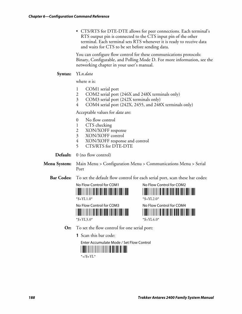
Chapter 6—Configuration Command Reference
188 Trakker Antares 2400 Family System Manual
• CTS/RTS for DTE-DTE allows for peer connections. Each terminal’s RTS output pin is connected to the CTS input pin of the other terminal. Each terminal sets RTS whenever it is ready to receive data and waits for CTS to be set before sending data.
You can configure flow control for these communications protocols: Binary, Configurable, and Polling Mode D. For more information, see the networking chapter in your user’s manual.
Syntax: YLn.data
where n is:
1 COM1 serial port 2 COM2 serial port (246X and 248X terminals only) 3 COM3 serial port (242X terminals only) 4 COM4 serial port (242X, 2455, and 248X terminals only)
Acceptable values for data are:
0 No flow control 1 CTS checking 2 XON/XOFF response 3 XON/XOFF control 4 XON/XOFF response and control 5 CTS/RTS for DTE-DTE
Default: 0 (no flow control)
Menu System: Main Menu > Configuration Menu > Communications Menu > Serial Port
Bar Codes: To set the default flow control for each serial port, scan these bar codes:
No Flow Control for COM1 No Flow Control for COM2
*$+YL1.0* *$+YL2.0* *$+YL1.0* *$+YL2.0*
No Flow Control for COM3 No Flow Control for COM4
*$+YL3.0* *$+YL4.0* *$+YL3.0* *$+YL4.0*
Or: To set the flow control for one serial port:
1 Scan this bar code:
Enter Accumulate Mode / Set Flow Control
*+/$+YL* *+/$+YL*
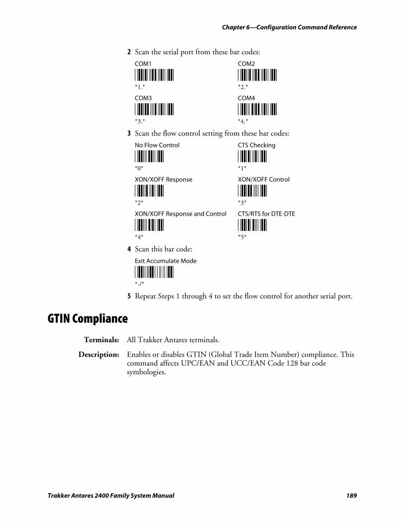
Chapter 6—Configuration Command Reference
Trakker Antares 2400 Family System Manual 189
2 Scan the serial port from these bar codes:
COM1 COM2
*1.* *2.* *1.* *2.*
COM3 COM4
*3.* *4.* *3.* *4.*
3 Scan the flow control setting from these bar codes:
No Flow Control CTS Checking
*0* *1* *0* *1*
XON/XOFF Response XON/XOFF Control
*2* *3* *2* *3*
XON/XOFF Response and Control CTS/RTS for DTE-DTE
*4* *5* *4* *5*
4 Scan this bar code:
Exit Accumulate Mode
*-/* *-/*
5 Repeat Steps 1 through 4 to set the flow control for another serial port.
GTIN Compliance
Terminals: All Trakker Antares terminals.
Description: Enables or disables GTIN (Global Trade Item Number) compliance. This command affects UPC/EAN and UCC/EAN Code 128 bar code symbologies.
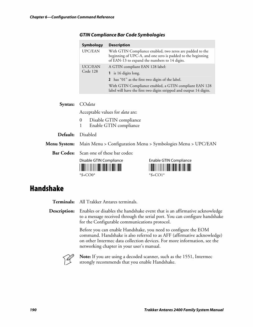
Chapter 6—Configuration Command Reference
190 Trakker Antares 2400 Family System Manual
GTIN Compliance Bar Code Symbologies
Symbology Description
UPC/EAN With GTIN Compliance enabled, two zeros are padded to the beginning of UPC-A, and one zero is padded to the beginning of EAN-13 to expand the numbers to 14 digits.
UCC/EAN Code 128
A GTIN compliant EAN 128 label:
1 is 16 digits long.
2 has “01” as the first two digits of the label.
With GTIN Compliance enabled, a GTIN compliant EAN 128 label will have the first two digits stripped and output 14 digits.
Syntax: COdata
Acceptable values for data are:
0 Disable GTIN compliance 1 Enable GTIN compliance
Default: Disabled
Menu System: Main Menu > Configuration Menu > Symbologies Menu > UPC/EAN
Bar Codes: Scan one of these bar codes:
Disable GTIN Compliance Enable GTIN Compliance
*$+CO0* *$+CO1* *$+CO0* *$+CO1*
Handshake
Terminals: All Trakker Antares terminals.
Description: Enables or disables the handshake event that is an affirmative acknowledge to a message received through the serial port. You can configure handshake for the Configurable communications protocol.
Before you can enable Handshake, you need to configure the EOM command. Handshake is also referred to as AFF (affirmative acknowledge) on other Intermec data collection devices. For more information, see the networking chapter in your user’s manual.
Note: If you are using a decoded scanner, such as the 1551, Intermec strongly recommends that you enable Handshake.
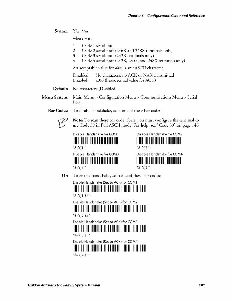
Chapter 6—Configuration Command Reference
Trakker Antares 2400 Family System Manual 191
Syntax: YJn.data
where n is:
1 COM1 serial port 2 COM2 serial port (246X and 248X terminals only) 3 COM3 serial port (242X terminals only) 4 COM4 serial port (242X, 2455, and 248X terminals only)
An acceptable value for data is any ASCII character.
Disabled No characters, no ACK or NAK transmitted Enabled \x06 (hexadecimal value for ACK)
Default: No characters (Disabled)
Menu System: Main Menu > Configuration Menu > Communications Menu > Serial Port
Bar Codes: To disable handshake, scan one of these bar codes:
Note: To scan these bar code labels, you must configure the terminal to use Code 39 in Full ASCII mode. For help, see “Code 39” on page 146.
Disable Handshake for COM1 Disable Handshake for COM2
*$+YJ1.* *$+YJ2.* *$+YJ1.* *$+YJ2.*
Disable Handshake for COM3 Disable Handshake for COM4
*$+YJ3.* *$+YJ4.* *$+YJ3.* *$+YJ4.*
Or: To enable handshake, scan one of these bar codes:
Enable Handshake (Set to ACK) for COM1
*/D/KYJ1/N$F* *$+YJ1.$F*
Enable Handshake (Set to ACK) for COM2
*/D/KYJ2/N$F* *$+YJ2.$F*
Enable Handshake (Set to ACK) for COM3
*/D/KYJ3/N$F* *$+YJ3.$F*
Enable Handshake (Set to ACK) for COM4
*/D/KYJ4/N$F* *$+YJ4.$F*
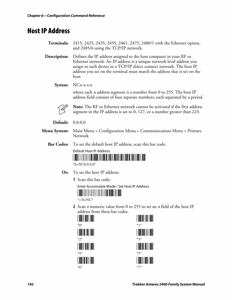
Chapter 6—Configuration Command Reference
192 Trakker Antares 2400 Family System Manual
Host IP Address
Terminals: 2415, 2425, 2435, 2455, 2461, 2475, 2480/1 with the Ethernet option, and 2485/6 using the TCP/IP network.
Description: Defines the IP address assigned to the host computer in your RF or Ethernet network. An IP address is a unique network level address you assign to each device in a TCP/IP direct connect network. The host IP address you set on the terminal must match the address that is set on the host.
Syntax: NCn.n.n.n
where each n address segment is a number from 0 to 255. The host IP address field consists of four separate numbers, each separated by a period.
Note: The RF or Ethernet network cannot be activated if the first address segment in the IP address is set to 0, 127, or a number greater than 223.
Default: 0.0.0.0
Menu System: Main Menu > Configuration Menu > Communications Menu > Primary Network
Bar Codes: To set the default host IP address, scan this bar code:
Default Host IP Address
*$+NC0.0.0.0* *$+NC0.0.0.0*
Or: To set the host IP address:
1 Scan this bar code:
Enter Accumulate Mode / Set Host IP Address
*+/$+NC* *+/$+NC*
2 Scan a numeric value from 0 to 255 to set an n field of the host IP address from these bar codes.
*0* *1* *0* *1*
*2* *3* *2* *3*
*4* *5* *4* *5*
*6* *7* *6* *7*
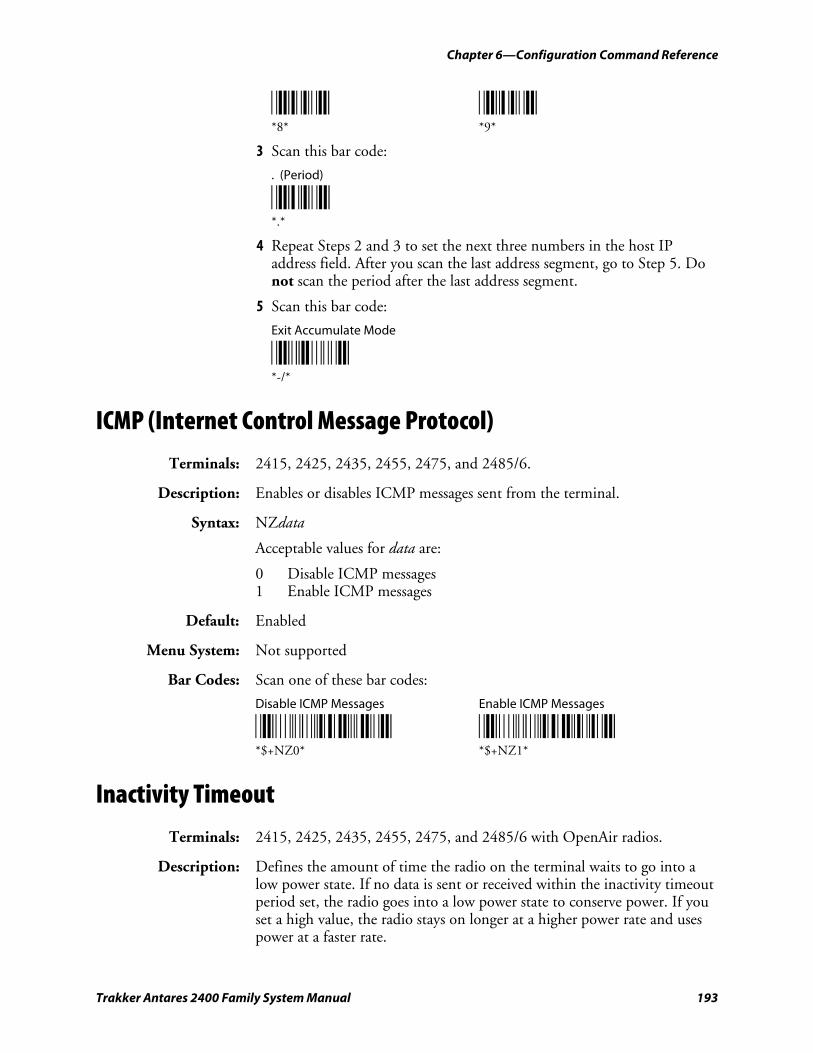
Chapter 6—Configuration Command Reference
Trakker Antares 2400 Family System Manual 193
*8* *9* *8* *9*
3 Scan this bar code:
. (Period)
*.* *.*
4 Repeat Steps 2 and 3 to set the next three numbers in the host IP address field. After you scan the last address segment, go to Step 5. Do not scan the period after the last address segment.
5 Scan this bar code:
Exit Accumulate Mode
*-/* *-/*
ICMP (Internet Control Message Protocol)
Terminals: 2415, 2425, 2435, 2455, 2475, and 2485/6.
Description: Enables or disables ICMP messages sent from the terminal.
Syntax: NZdata
Acceptable values for data are:
0 Disable ICMP messages 1 Enable ICMP messages
Default: Enabled
Menu System: Not supported
Bar Codes: Scan one of these bar codes:
Disable ICMP Messages Enable ICMP Messages
*$+NZ0* *$+NZ1* *$+NZ0* *$+NZ1*
Inactivity Timeout
Terminals: 2415, 2425, 2435, 2455, 2475, and 2485/6 with OpenAir radios.
Description: Defines the amount of time the radio on the terminal waits to go into a low power state. If no data is sent or received within the inactivity timeout period set, the radio goes into a low power state to conserve power. If you set a high value, the radio stays on longer at a higher power rate and uses power at a faster rate.
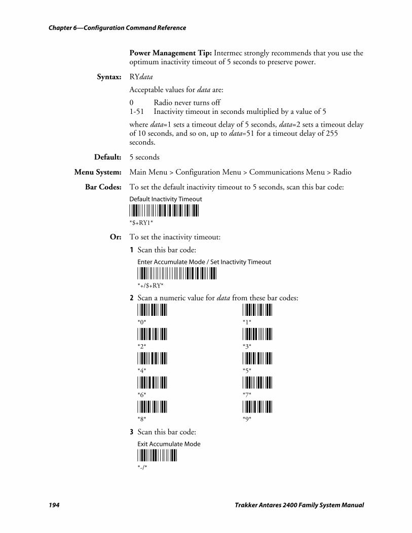
Chapter 6—Configuration Command Reference
194 Trakker Antares 2400 Family System Manual
Power Management Tip: Intermec strongly recommends that you use the optimum inactivity timeout of 5 seconds to preserve power.
Syntax: RYdata
Acceptable values for data are:
0 Radio never turns off 1-51 Inactivity timeout in seconds multiplied by a value of 5
where data=1 sets a timeout delay of 5 seconds, data=2 sets a timeout delay of 10 seconds, and so on, up to data=51 for a timeout delay of 255 seconds.
Default: 5 seconds
Menu System: Main Menu > Configuration Menu > Communications Menu > Radio
Bar Codes: To set the default inactivity timeout to 5 seconds, scan this bar code:
Default Inactivity Timeout
*$+RY1* *$+RY1*
Or: To set the inactivity timeout:
1 Scan this bar code:
Enter Accumulate Mode / Set Inactivity Timeout
*+/$+RY* *+/$+RY*
2 Scan a numeric value for data from these bar codes:
*0* *1* *0* *1*
*2* *3* *2* *3*
*4* *5* *4* *5*
*6* *7* *6* *7*
*8* *9* *8* *9*
3 Scan this bar code:
Exit Accumulate Mode
*-/* *-/*
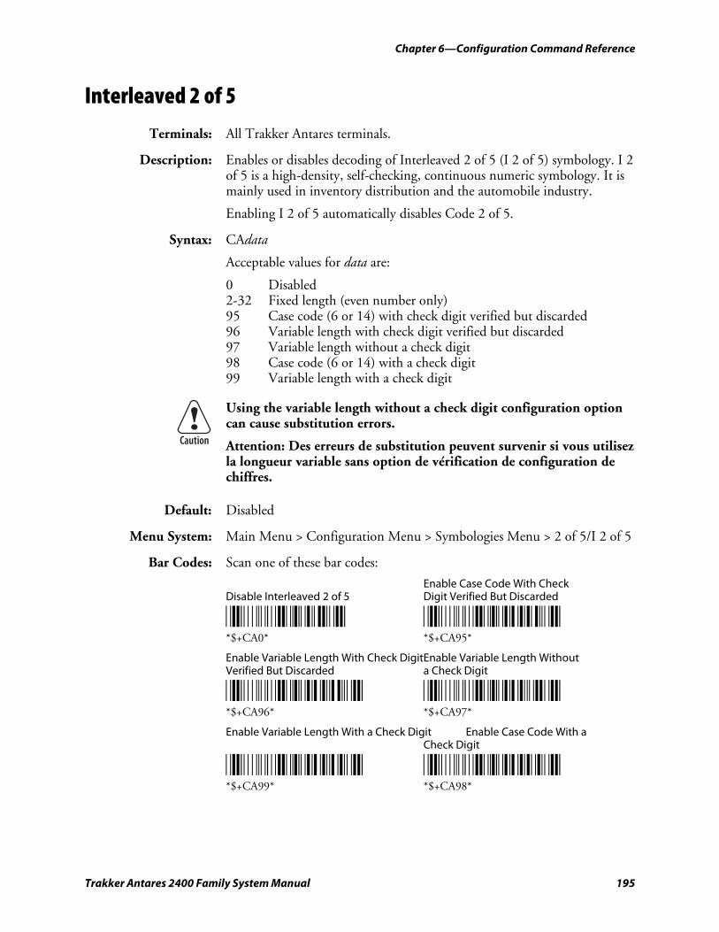
Chapter 6—Configuration Command Reference
Trakker Antares 2400 Family System Manual 195
Interleaved 2 of 5
Terminals: All Trakker Antares terminals.
Description: Enables or disables decoding of Interleaved 2 of 5 (I 2 of 5) symbology. I 2 of 5 is a high-density, self-checking, continuous numeric symbology. It is mainly used in inventory distribution and the automobile industry.
Enabling I 2 of 5 automatically disables Code 2 of 5.
Syntax: CAdata
Acceptable values for data are:
0 Disabled 2-32 Fixed length (even number only) 95 Case code (6 or 14) with check digit verified but discarded 96 Variable length with check digit verified but discarded 97 Variable length without a check digit 98 Case code (6 or 14) with a check digit 99 Variable length with a check digit
Using the variable length without a check digit configuration option can cause substitution errors.
Attention: Des erreurs de substitution peuvent survenir si vous utilisez la longueur variable sans option de vérification de configuration de chiffres.
Default: Disabled
Menu System: Main Menu > Configuration Menu > Symbologies Menu > 2 of 5/I 2 of 5
Bar Codes: Scan one of these bar codes:
Enable Case Code With Check Disable Interleaved 2 of 5 Digit Verified But Discarded
*$+CA0* *$+CA95* *$+CA0* *$+CA95*
Enable Variable Length With Check DigitEnable Variable Length Without Verified But Discarded a Check Digit
*$+CA96* *$+CA97* *$+CA96* *$+CA97*
Enable Variable Length With a Check Digit Enable Case Code With a Check Digit
*$+CA99* *$+CA98* *$+CA99* *$+CA98*
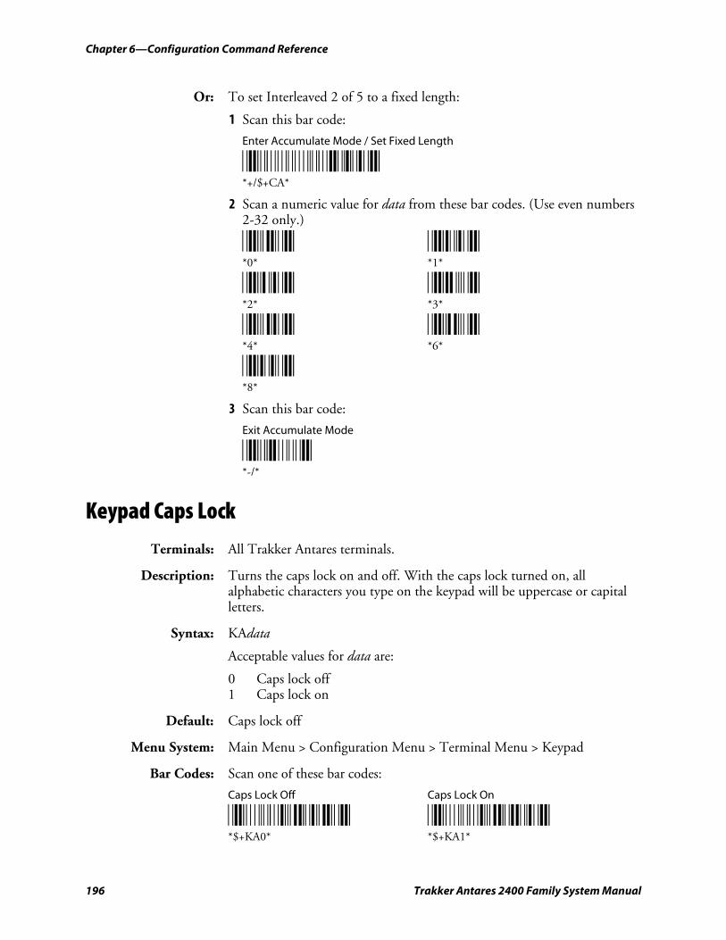
Chapter 6—Configuration Command Reference
196 Trakker Antares 2400 Family System Manual
Or: To set Interleaved 2 of 5 to a fixed length:
1 Scan this bar code:
Enter Accumulate Mode / Set Fixed Length
*+/$+CA* *+/$+CA*
2 Scan a numeric value for data from these bar codes. (Use even numbers 2-32 only.)
*0* *1* *0* *1*
*2* *3* *2* *3*
*4* *6* *4* *6*
*8* *8*
3 Scan this bar code:
Exit Accumulate Mode
*-/* *-/*
Keypad Caps Lock
Terminals: All Trakker Antares terminals.
Description: Turns the caps lock on and off. With the caps lock turned on, all alphabetic characters you type on the keypad will be uppercase or capital letters.
Syntax: KAdata
Acceptable values for data are:
0 Caps lock off 1 Caps lock on
Default: Caps lock off
Menu System: Main Menu > Configuration Menu > Terminal Menu > Keypad
Bar Codes: Scan one of these bar codes:
Caps Lock Off Caps Lock On
*$+KA0* *$+KA1* *$+KA0* *$+KA1*
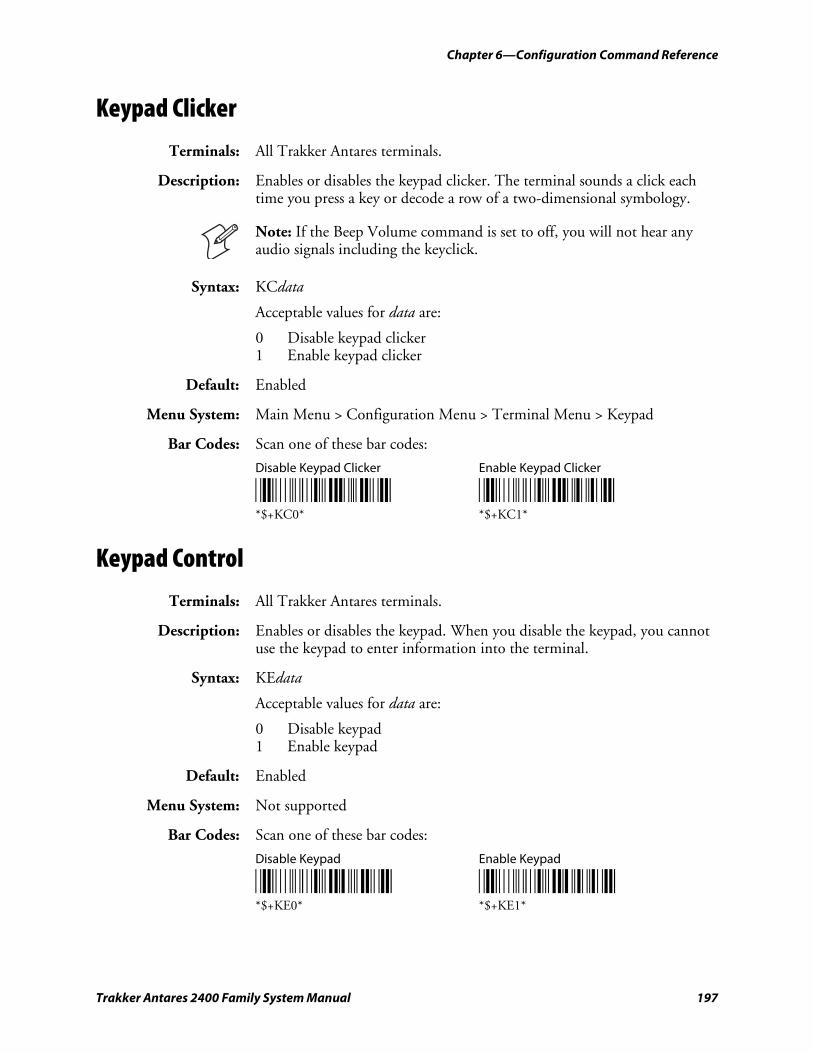
Chapter 6—Configuration Command Reference
Trakker Antares 2400 Family System Manual 197
Keypad Clicker
Terminals: All Trakker Antares terminals.
Description: Enables or disables the keypad clicker. The terminal sounds a click each time you press a key or decode a row of a two-dimensional symbology.
Note: If the Beep Volume command is set to off, you will not hear any audio signals including the keyclick.
Syntax: KCdata
Acceptable values for data are:
0 Disable keypad clicker 1 Enable keypad clicker
Default: Enabled
Menu System: Main Menu > Configuration Menu > Terminal Menu > Keypad
Bar Codes: Scan one of these bar codes:
Disable Keypad Clicker Enable Keypad Clicker
*$+KC0* *$+KC1* *$+KC0* *$+KC1*
Keypad Control
Terminals: All Trakker Antares terminals.
Description: Enables or disables the keypad. When you disable the keypad, you cannot use the keypad to enter information into the terminal.
Syntax: KEdata
Acceptable values for data are:
0 Disable keypad 1 Enable keypad
Default: Enabled
Menu System: Not supported
Bar Codes: Scan one of these bar codes:
Disable Keypad Enable Keypad
*$+KE0* *$+KE1* *$+KE0* *$+KE1*
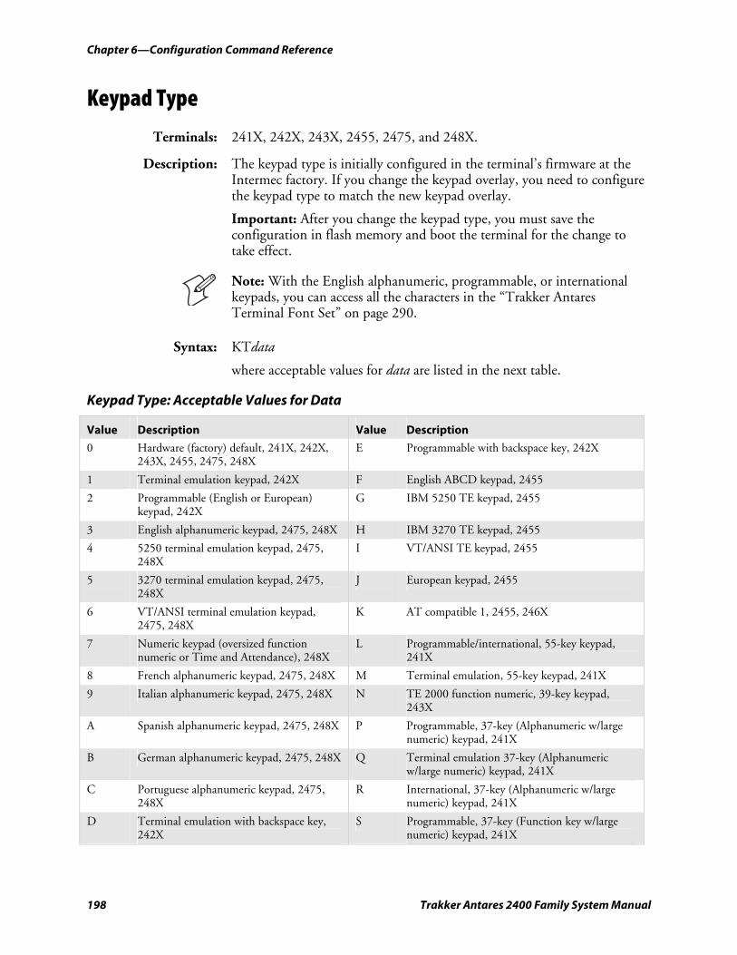
Chapter 6—Configuration Command Reference
198 Trakker Antares 2400 Family System Manual
Keypad Type
Terminals: 241X, 242X, 243X, 2455, 2475, and 248X.
Description: The keypad type is initially configured in the terminal’s firmware at the Intermec factory. If you change the keypad overlay, you need to configure the keypad type to match the new keypad overlay.
Important: After you change the keypad type, you must save the configuration in flash memory and boot the terminal for the change to take effect.
Note: With the English alphanumeric, programmable, or international keypads, you can access all the characters in the “Trakker Antares Terminal Font Set” on page 290.
Syntax: KTdata
where acceptable values for data are listed in the next table.
Keypad Type: Acceptable Values for Data
Value Description Value Description
0 Hardware (factory) default, 241X, 242X, 243X, 2455, 2475, 248X
E Programmable with backspace key, 242X
1 Terminal emulation keypad, 242X F English ABCD keypad, 2455
2 Programmable (English or European) keypad, 242X
G IBM 5250 TE keypad, 2455
3 English alphanumeric keypad, 2475, 248X H IBM 3270 TE keypad, 2455
4 5250 terminal emulation keypad, 2475, 248X
I VT/ANSI TE keypad, 2455
5 3270 terminal emulation keypad, 2475, 248X
J European keypad, 2455
6 VT/ANSI terminal emulation keypad, 2475, 248X
K AT compatible 1, 2455, 246X
7 Numeric keypad (oversized function numeric or Time and Attendance), 248X
L Programmable/international, 55-key keypad, 241X
8 French alphanumeric keypad, 2475, 248X M Terminal emulation, 55-key keypad, 241X
9 Italian alphanumeric keypad, 2475, 248X N TE 2000 function numeric, 39-key keypad, 243X
A Spanish alphanumeric keypad, 2475, 248X P Programmable, 37-key (Alphanumeric w/large numeric) keypad, 241X
B German alphanumeric keypad, 2475, 248X Q Terminal emulation 37-key (Alphanumeric w/large numeric) keypad, 241X
C Portuguese alphanumeric keypad, 2475, 248X
R International, 37-key (Alphanumeric w/large numeric) keypad, 241X
D Terminal emulation with backspace key, 242X
S Programmable, 37-key (Function key w/large numeric) keypad, 241X
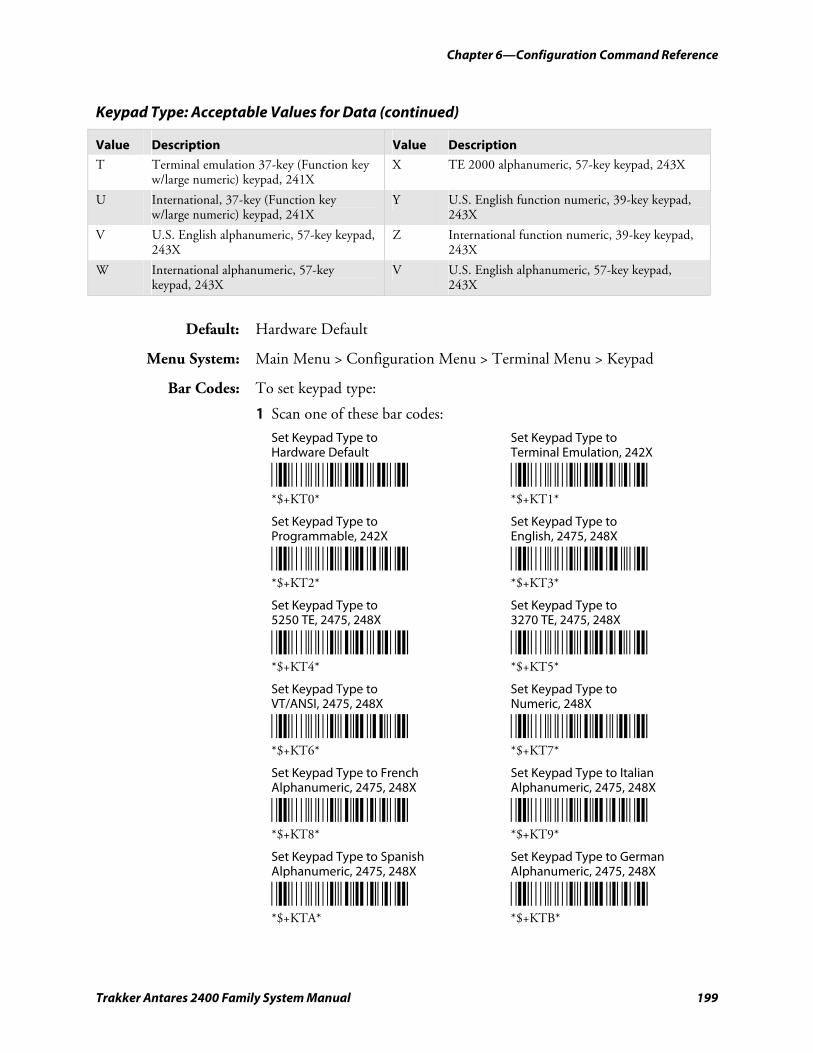
Chapter 6—Configuration Command Reference
Trakker Antares 2400 Family System Manual 199
Keypad Type: Acceptable Values for Data (continued)
Value Description Value Description
T Terminal emulation 37-key (Function key w/large numeric) keypad, 241X
X TE 2000 alphanumeric, 57-key keypad, 243X
U International, 37-key (Function key w/large numeric) keypad, 241X
Y U.S. English function numeric, 39-key keypad, 243X
V U.S. English alphanumeric, 57-key keypad, 243X
Z International function numeric, 39-key keypad, 243X
W International alphanumeric, 57-key keypad, 243X
V U.S. English alphanumeric, 57-key keypad, 243X
Default: Hardware Default
Menu System: Main Menu > Configuration Menu > Terminal Menu > Keypad
Bar Codes: To set keypad type:
1 Scan one of these bar codes:
Set Keypad Type to Set Keypad Type to Hardware Default Terminal Emulation, 242X
*$+KT0* *$+KT1* *$+KT0* *$+KT1*
Set Keypad Type to Set Keypad Type to Programmable, 242X English, 2475, 248X
*$+KT2* *$+KT3* *$+KT2* *$+KT3*
Set Keypad Type to Set Keypad Type to 5250 TE, 2475, 248X 3270 TE, 2475, 248X
*$+KT4* *$+KT5* *$+KT4* *$+KT5*
Set Keypad Type to Set Keypad Type to VT/ANSI, 2475, 248X Numeric, 248X
*$+KT6* *$+KT7* *$+KT6* *$+KT7*
Set Keypad Type to French Set Keypad Type to Italian Alphanumeric, 2475, 248X Alphanumeric, 2475, 248X
*$+KT8* *$+KT9* *$+KT8* *$+KT9*
Set Keypad Type to Spanish Set Keypad Type to German Alphanumeric, 2475, 248X Alphanumeric, 2475, 248X
*$+KTA* *$+KTB* *$+KTA* *$+KTB*
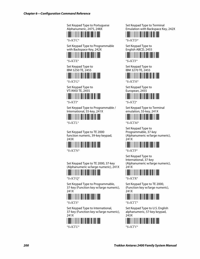
Chapter 6—Configuration Command Reference
200 Trakker Antares 2400 Family System Manual
Set Keypad Type to Portuguese Set Keypad Type to Terminal Alphanumeric, 2475, 248X Emulation with Backspace Key, 242X
*$+KTC* *$+KTD* *$+KTC* *$+KTD*
Set Keypad Type to Programmable Set Keypad Type to with Backspace Key, 242X English ABCD, 2455
*$+KTE* *$+KTF* *$+KTE* *$+KTF*
Set Keypad Type to Set Keypad Type to IBM 5250 TE, 2455 IBM 3270 TE, 2455
*$+KTG* *$+KTH* *$+KTG* *$+KTH*
Set Keypad Type to Set Keypad Type to VT/ANSI TE, 2455 European, 2455
*$+KTI* *$+KTJ* *$+KTI* *$+KTJ*
Set Keypad Type to Programmable / Set Keypad Type to Terminal International, 55-key, 241X emulation, 55-key, 241X
*$+KTL* *$+KTM* *$+KTL* *$+KTM*
Set Keypad Type to Set Keypad Type to TE 2000 Programmable, 37-key function numeric, 39-key keypad, (Alphanumeric w/large numeric), 243X 241X
*$+KTN* *$+KTP* *$+KTN* *$+KTP*
Set Keypad Type to International, 37-key
Set Keypad Type to TE 2000, 37-key (Alphanumeric w/large numeric), (Alphanumeric w/large numeric), 241X 241X
*$+KTQ* *$+KTR* *$+KTQ* *$+KTR*
Set Keypad Type to Programmable, Set Keypad Type to TE 2000, 37-key (Function key w/large numeric), (Function key w/large numeric),
241X 241X
*$+KTS* *$+KTT* *$+KTS* *$+KTT*
Set Keypad Type to International, Set Keypad Type to U.S. English 37-key (Function key w/large numeric), alphanumeric, 57-key keypad, 241X 243X
*$+KTU* *$+KTV* *$+KTU* *$+KTV*
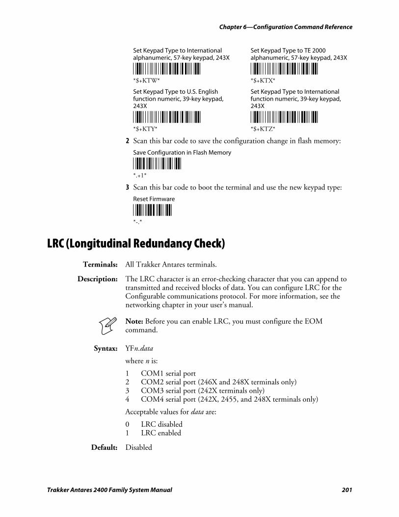
Chapter 6—Configuration Command Reference
Trakker Antares 2400 Family System Manual 201
Set Keypad Type to International Set Keypad Type to TE 2000 alphanumeric, 57-key keypad, 243X alphanumeric, 57-key keypad, 243X
*$+KTW* *$+KTX* *$+KTW* *$+KTX*
Set Keypad Type to U.S. English Set Keypad Type to International function numeric, 39-key keypad, function numeric, 39-key keypad,
243X 243X
*$+KTY* *$+KTZ* *$+KTY* *$+KTZ*
2 Scan this bar code to save the configuration change in flash memory:
Save Configuration in Flash Memory
*.+1* *.+1*
3 Scan this bar code to boot the terminal and use the new keypad type:
Reset Firmware
*-.* *-.*
LRC (Longitudinal Redundancy Check)
Terminals: All Trakker Antares terminals.
Description: The LRC character is an error-checking character that you can append to transmitted and received blocks of data. You can configure LRC for the Configurable communications protocol. For more information, see the networking chapter in your user’s manual.
Note: Before you can enable LRC, you must configure the EOM command.
Syntax: YFn.data
where n is:
1 COM1 serial port 2 COM2 serial port (246X and 248X terminals only) 3 COM3 serial port (242X terminals only) 4 COM4 serial port (242X, 2455, and 248X terminals only)
Acceptable values for data are:
0 LRC disabled 1 LRC enabled
Default: Disabled
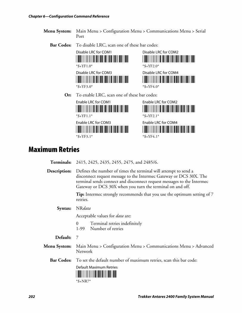
Chapter 6—Configuration Command Reference
202 Trakker Antares 2400 Family System Manual
Menu System: Main Menu > Configuration Menu > Communications Menu > Serial Port
Bar Codes: To disable LRC, scan one of these bar codes:
Disable LRC for COM1 Disable LRC for COM2
*$+YF1.0* *$+YF2.0* *$+YF1.0* *$+YF2.0*
Disable LRC for COM3 Disable LRC for COM4
*$+YF3.0* *$+YF4.0* *$+YF3.0* *$+YF4.0*
Or: To enable LRC, scan one of these bar codes:
Enable LRC for COM1 Enable LRC for COM2
*$+YF1.1* *$+YF2.1* *$+YF1.1* *$+YF2.1*
Enable LRC for COM3 Enable LRC for COM4
*$+YF3.1* *$+YF4.1* *$+YF3.1* *$+YF4.1*
Maximum Retries
Terminals: 2415, 2425, 2435, 2455, 2475, and 2485/6.
Description: Defines the number of times the terminal will attempt to send a disconnect request message to the Intermec Gateway or DCS 30X. The terminal sends connect and disconnect request messages to the Intermec Gateway or DCS 30X when you turn the terminal on and off.
Tip: Intermec strongly recommends that you use the optimum setting of 7 retries.
Syntax: NRdata
Acceptable values for data are:
0 Terminal retries indefinitely 1-99 Number of retries
Default: 7
Menu System: Main Menu > Configuration Menu > Communications Menu > Advanced Network
Bar Codes: To set the default number of maximum retries, scan this bar code:
Default Maximum Retries
*$+NR7* *$+NR7*
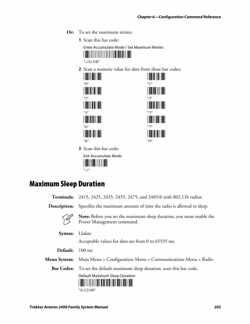
Chapter 6—Configuration Command Reference
Trakker Antares 2400 Family System Manual 203
Or: To set the maximum retries:
1 Scan this bar code:
Enter Accumulate Mode / Set Maximum Retries
*+/$+NR* *+/$+NR*
2 Scan a numeric value for data from these bar codes:
*0* *1* *0* *1*
*2* *3* *2* *3*
*4* *5* *4* *5*
*6* *7* *6* *7*
*8* *9* *8* *9*
3 Scan this bar code:
Exit Accumulate Mode
*-/* *-/*
Maximum Sleep Duration
Terminals: 2415, 2425, 2435, 2455, 2475, and 2485/6 with 802.11b radios.
Description: Specifies the maximum amount of time the radio is allowed to sleep.
Note: Before you set the maximum sleep duration, you must enable the Power Management command.
Syntax: LIdata
Acceptable values for data are from 0 to 65535 ms.
Default: 100 ms
Menu System: Main Menu > Configuration Menu > Communications Menu > Radio
Bar Codes: To set the default maximum sleep duration, scan this bar code:
Default Maximum Sleep Duration
*$+LI100* *$+LI100*
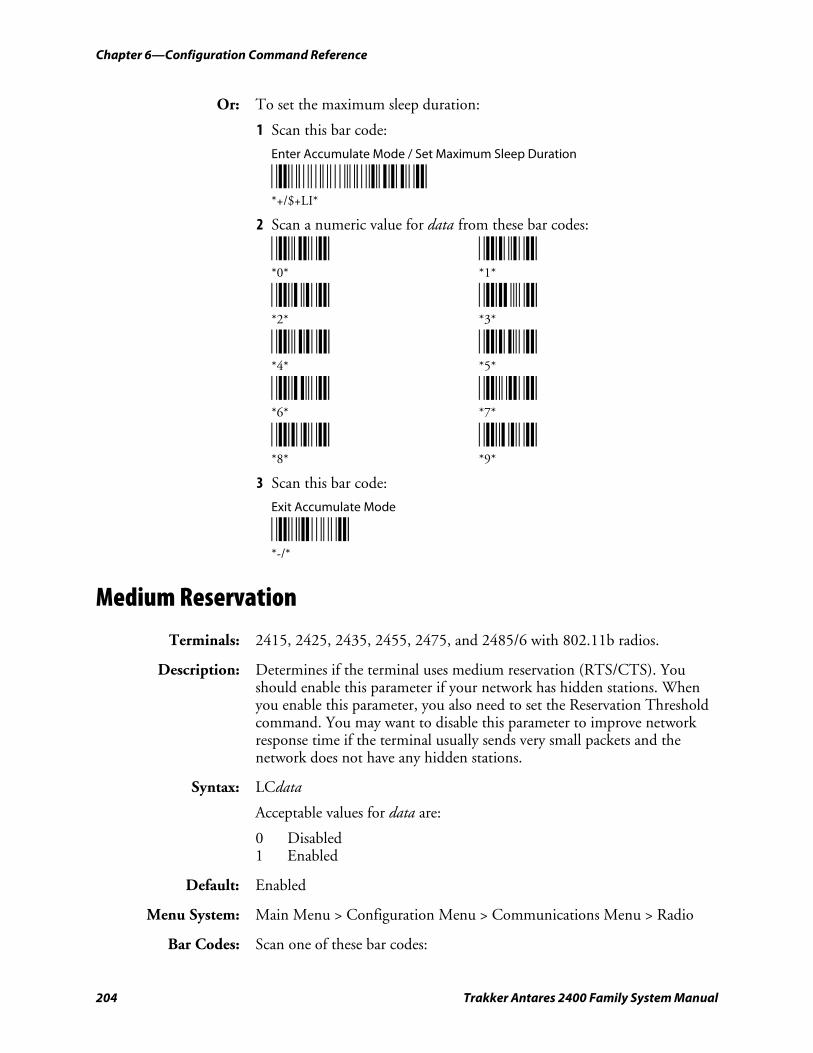
Chapter 6—Configuration Command Reference
204 Trakker Antares 2400 Family System Manual
Or: To set the maximum sleep duration:
1 Scan this bar code:
Enter Accumulate Mode / Set Maximum Sleep Duration
*+/$+LI* *+/$+LI*
2 Scan a numeric value for data from these bar codes:
*0* *1* *0* *1*
*2* *3* *2* *3*
*4* *5* *4* *5*
*6* *7* *6* *7*
*8* *9* *8* *9*
3 Scan this bar code:
Exit Accumulate Mode
*-/* *-/*
Medium Reservation
Terminals: 2415, 2425, 2435, 2455, 2475, and 2485/6 with 802.11b radios.
Description: Determines if the terminal uses medium reservation (RTS/CTS). You should enable this parameter if your network has hidden stations. When you enable this parameter, you also need to set the Reservation Threshold command. You may want to disable this parameter to improve network response time if the terminal usually sends very small packets and the network does not have any hidden stations.
Syntax: LCdata
Acceptable values for data are:
0 Disabled 1 Enabled
Default: Enabled
Menu System: Main Menu > Configuration Menu > Communications Menu > Radio
Bar Codes: Scan one of these bar codes:
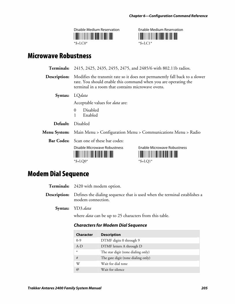
Chapter 6—Configuration Command Reference
Trakker Antares 2400 Family System Manual 205
Disable Medium Reservation Enable Medium Reservation
*$+LC0* *$+LC1* *$+LC0* *$+LC1*
Microwave Robustness
Terminals: 2415, 2425, 2435, 2455, 2475, and 2485/6 with 802.11b radios.
Description: Modifies the transmit rate so it does not permanently fall back to a slower rate. You should enable this command when you are operating the terminal in a room that contains microwave ovens.
Syntax: LQdata
Acceptable values for data are:
0 Disabled 1 Enabled
Default: Disabled
Menu System: Main Menu > Configuration Menu > Communications Menu > Radio
Bar Codes: Scan one of these bar codes:
Disable Microwave Robustness Enable Microwave Robustness
*$+LQ0* *$+LQ1* *$+LQ0* *$+LQ1*
Modem Dial Sequence
Terminals: 2420 with modem option.
Description: Defines the dialing sequence that is used when the terminal establishes a modem connection.
Syntax: YD3.data
where data can be up to 25 characters from this table.
Characters for Modem Dial Sequence
Character Description
0-9 DTMF digits 0 through 9
A-D DTMF letters A through D
* The star digit (tone dialing only)
# The gate digit (tone dialing only)
W Wait for dial tone
@ Wait for silence
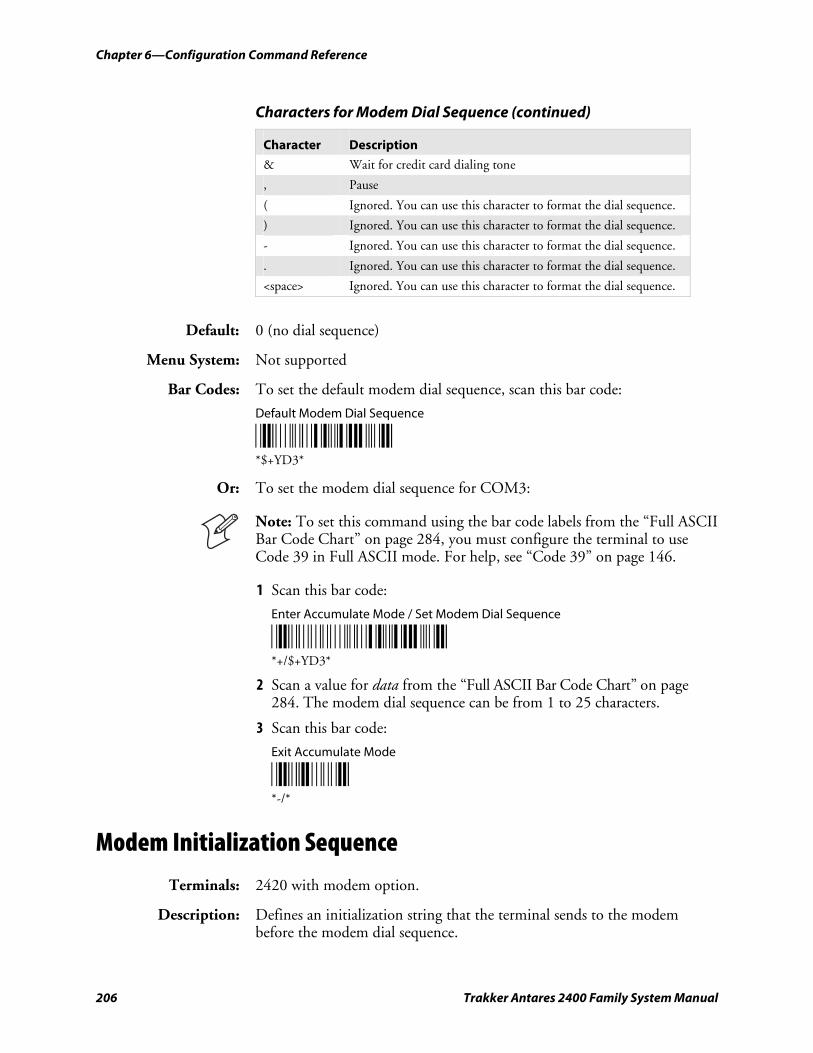
Chapter 6—Configuration Command Reference
206 Trakker Antares 2400 Family System Manual
Characters for Modem Dial Sequence (continued)
Character Description
& Wait for credit card dialing tone
, Pause
( Ignored. You can use this character to format the dial sequence.
) Ignored. You can use this character to format the dial sequence.
- Ignored. You can use this character to format the dial sequence.
. Ignored. You can use this character to format the dial sequence.
<space> Ignored. You can use this character to format the dial sequence.
Default: 0 (no dial sequence)
Menu System: Not supported
Bar Codes: To set the default modem dial sequence, scan this bar code:
Default Modem Dial Sequence
*$+YD3* *$+YD3*
Or: To set the modem dial sequence for COM3:
Note: To set this command using the bar code labels from the “Full ASCII Bar Code Chart” on page 284, you must configure the terminal to use Code 39 in Full ASCII mode. For help, see “Code 39” on page 146.
1 Scan this bar code:
Enter Accumulate Mode / Set Modem Dial Sequence
*+/$+YD3* *+/$+YD3*
2 Scan a value for data from the “Full ASCII Bar Code Chart” on page 284. The modem dial sequence can be from 1 to 25 characters.
3 Scan this bar code:
Exit Accumulate Mode
*-/* *-/*
Modem Initialization Sequence
Terminals: 2420 with modem option.
Description: Defines an initialization string that the terminal sends to the modem before the modem dial sequence.
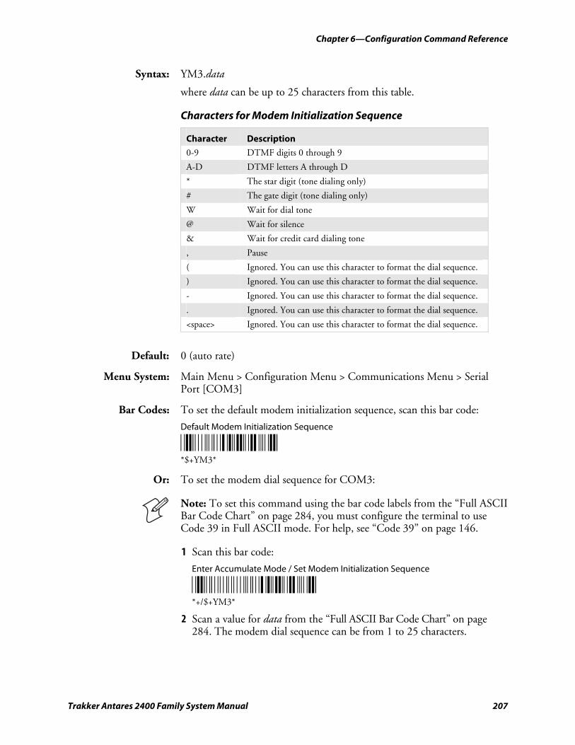
Chapter 6—Configuration Command Reference
Trakker Antares 2400 Family System Manual 207
Syntax: YM3.data
where data can be up to 25 characters from this table.
Characters for Modem Initialization Sequence
Character Description
0-9 DTMF digits 0 through 9
A-D DTMF letters A through D
* The star digit (tone dialing only)
# The gate digit (tone dialing only)
W Wait for dial tone
@ Wait for silence
& Wait for credit card dialing tone
, Pause
( Ignored. You can use this character to format the dial sequence.
) Ignored. You can use this character to format the dial sequence.
- Ignored. You can use this character to format the dial sequence.
. Ignored. You can use this character to format the dial sequence.
<space> Ignored. You can use this character to format the dial sequence.
Default: 0 (auto rate)
Menu System: Main Menu > Configuration Menu > Communications Menu > Serial Port [COM3]
Bar Codes: To set the default modem initialization sequence, scan this bar code:
Default Modem Initialization Sequence
*$+YM3* *$+YM3*
Or: To set the modem dial sequence for COM3:
Note: To set this command using the bar code labels from the “Full ASCII Bar Code Chart” on page 284, you must configure the terminal to use Code 39 in Full ASCII mode. For help, see “Code 39” on page 146.
1 Scan this bar code:
Enter Accumulate Mode / Set Modem Initialization Sequence
*+/$+YM3* *+/$+YM3*
2 Scan a value for data from the “Full ASCII Bar Code Chart” on page 284. The modem dial sequence can be from 1 to 25 characters.
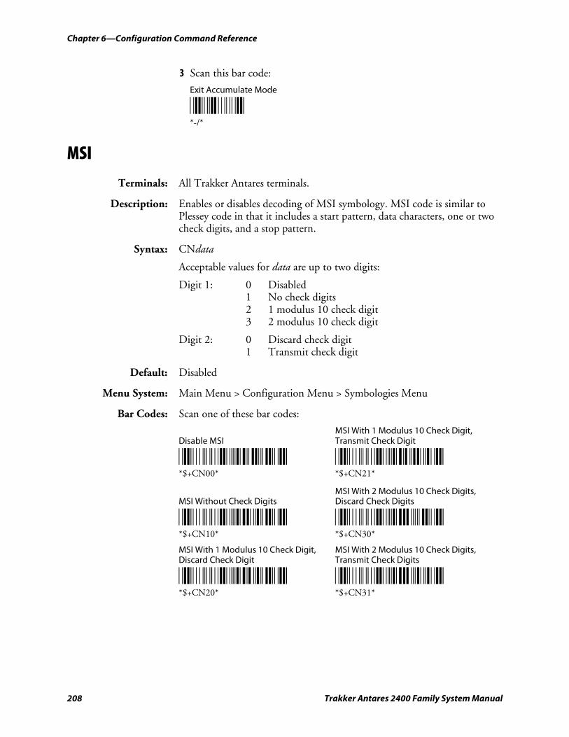
Chapter 6—Configuration Command Reference
208 Trakker Antares 2400 Family System Manual
3 Scan this bar code:
Exit Accumulate Mode
*-/* *-/*
MSI
Terminals: All Trakker Antares terminals.
Description: Enables or disables decoding of MSI symbology. MSI code is similar to Plessey code in that it includes a start pattern, data characters, one or two check digits, and a stop pattern.
Syntax: CNdata
Acceptable values for data are up to two digits:
Digit 1: 0 Disabled 1 No check digits 2 1 modulus 10 check digit 3 2 modulus 10 check digit
Digit 2: 0 Discard check digit 1 Transmit check digit
Default: Disabled
Menu System: Main Menu > Configuration Menu > Symbologies Menu
Bar Codes: Scan one of these bar codes:
MSI With 1 Modulus 10 Check Digit, Disable MSI Transmit Check Digit
*$+CN00* *$+CN21* *$+CN00* *$+CN21*
MSI With 2 Modulus 10 Check Digits, MSI Without Check Digits Discard Check Digits
*$+CN10* *$+CN30* *$+CN10* *$+CN30*
MSI With 1 Modulus 10 Check Digit, MSI With 2 Modulus 10 Check Digits, Discard Check Digit Transmit Check Digits
*$+CN20* *$+CN31* *$+CN20* *$+CN31*
Chapter 6—Configuration Command Reference
Trakker Antares 2400 Family System Manual 209
Multi-Drop Address
Terminals: 2460 and 248X with enhanced I/O board option.
Description: Defines the address of the communications port when you are using Multi-Drop protocol on COM2. Each multi-drop address has unique POL and SEL characters that are automatically set when you configure the address. The POL and SEL combination for each address is listed in the next table.
POL and SEL Characters for Multi-Drop Addresses
Address POL SEL Address POL SEL
A FS GS Q < =
B RS US R > ?
C SP ! S @ A
D “ # T B C
E $ % U D E
F & ‘ V F G
G ( ) W H I
H * + X J K
I ‘ - Y L M
J . / Z N O
K 0 1 0 P Q
L 2 3 1 R S
M 4 5 2 T U
N 6 7 3 V W
O 8 9 4 X Y
P : ;
Syntax: YN2.data
where data can be an alphanumeric value from A through Z or 0 to 5.
Default: A
Menu System: Main Menu > Configuration Menu > Communications Menu > Serial Port [COM2]
Bar Codes: To set the default multi-drop address:
Default Multi-Drop Address (A) for COM2
*$+YN2.A* *$+YN2.A*
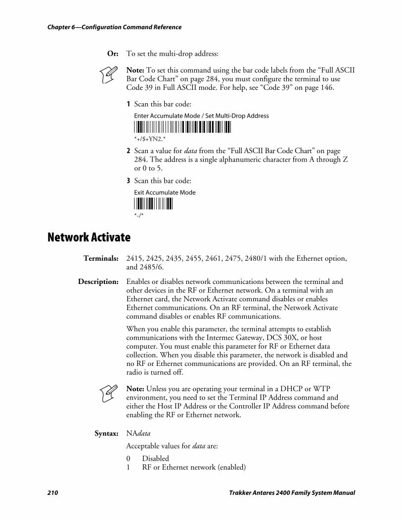
Chapter 6—Configuration Command Reference
210 Trakker Antares 2400 Family System Manual
Or: To set the multi-drop address:
Note: To set this command using the bar code labels from the “Full ASCII Bar Code Chart” on page 284, you must configure the terminal to use Code 39 in Full ASCII mode. For help, see “Code 39” on page 146.
1 Scan this bar code:
Enter Accumulate Mode / Set Multi-Drop Address
*+/$+YN2.* *+/$+YN2.*
2 Scan a value for data from the “Full ASCII Bar Code Chart” on page 284. The address is a single alphanumeric character from A through Z or 0 to 5.
3 Scan this bar code:
Exit Accumulate Mode
*-/* *-/*
Network Activate
Terminals: 2415, 2425, 2435, 2455, 2461, 2475, 2480/1 with the Ethernet option, and 2485/6.
Description: Enables or disables network communications between the terminal and other devices in the RF or Ethernet network. On a terminal with an Ethernet card, the Network Activate command disables or enables Ethernet communications. On an RF terminal, the Network Activate command disables or enables RF communications.
When you enable this parameter, the terminal attempts to establish communications with the Intermec Gateway, DCS 30X, or host computer. You must enable this parameter for RF or Ethernet data collection. When you disable this parameter, the network is disabled and no RF or Ethernet communications are provided. On an RF terminal, the radio is turned off.
Note: Unless you are operating your terminal in a DHCP or WTP environment, you need to set the Terminal IP Address command and either the Host IP Address or the Controller IP Address command before enabling the RF or Ethernet network.
Syntax: NAdata
Acceptable values for data are:
0 Disabled 1 RF or Ethernet network (enabled)
Chapter 6—Configuration Command Reference
Trakker Antares 2400 Family System Manual 211
Default: Disabled
Menu System: Main Menu > Configuration Menu > Communications Menu > Primary Network
Bar Codes: Scan one of these bar codes:
Disable Network Activate Enable RF or Ethernet Network
*$+NA0* *$+NA1* *$+NA0* *$+NA1*
Network Loopback
Terminals: 2415, 2425, 2435, 2455, 2475, and 2485/6.
Description: Transmits all messages received from the Intermec Gateway or DCS 30X back to the Intermec Gateway or DCS 30X. Messages received by the radio are not passed on to the terminal applications unless they are configuration commands. Messages continue to be looped back to the Intermec Gateway or DCS 30X as long as this feature is enabled. Messages originating from the terminal are still transmitted to the Intermec Gateway or DCS 30X.
Use the Network Loopback parameter to troubleshoot RF or Ethernet communications problems.
Syntax: NLdata
Acceptable values for data are:
0 Disabled 1 Enabled
Default: Disabled
Menu System: Main Menu > Configuration Menu > Communications Menu > Advanced Network
Bar Codes: Scan one of these bar codes:
Disable Network Loopback Enable Network Loopback
*$+NL0* *$+NL1* *$+NL0* *$+NL1*
Network Name
Terminals: 2415, 2425, 2435, 2455, 2475, and 2485/6 with 802.11b radios.
Description: Defines an RF subnetwork. To communicate, all access points and RF terminals in the subnetwork must have the same network name, which is case-sensitive. If you set this parameter to “ANY,” the terminal can
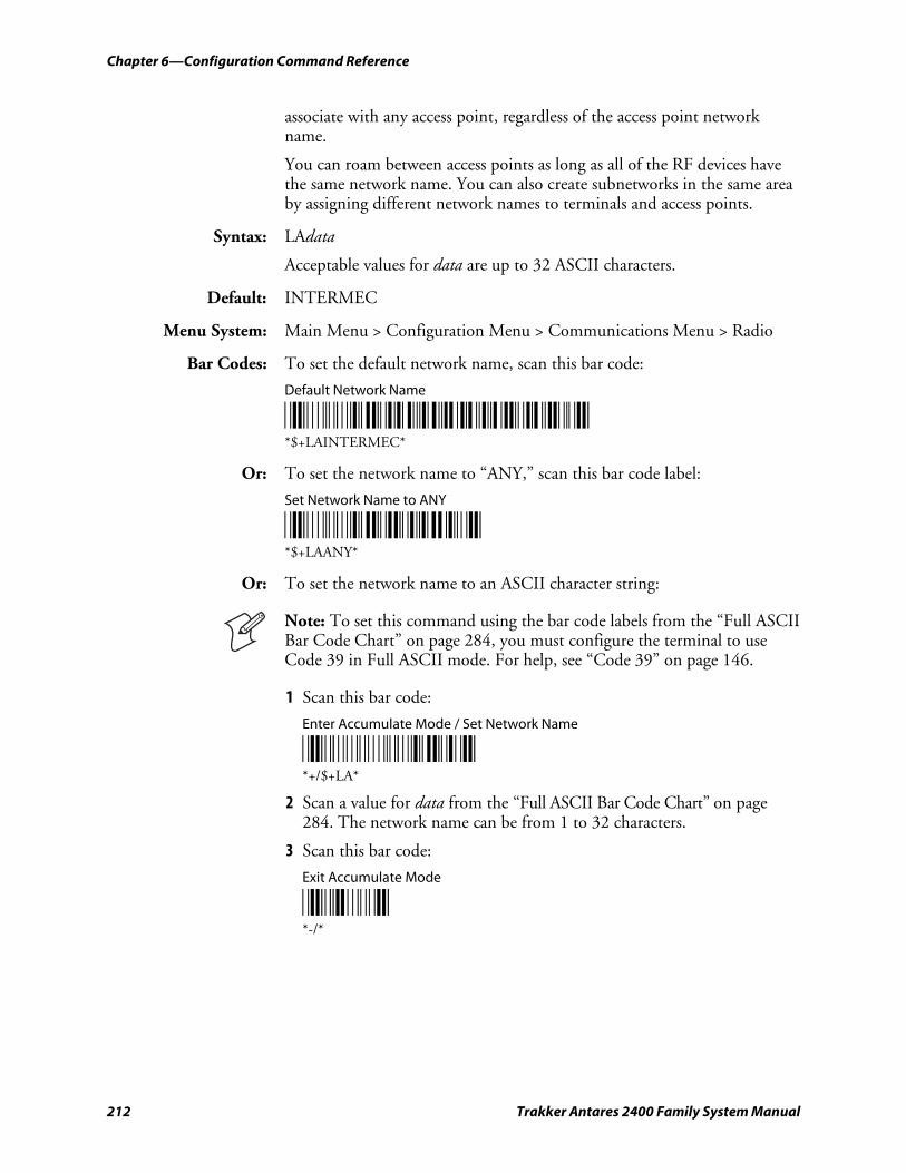
Chapter 6—Configuration Command Reference
212 Trakker Antares 2400 Family System Manual
associate with any access point, regardless of the access point network name.
You can roam between access points as long as all of the RF devices have the same network name. You can also create subnetworks in the same area by assigning different network names to terminals and access points.
Syntax: LAdata
Acceptable values for data are up to 32 ASCII characters.
Default: INTERMEC
Menu System: Main Menu > Configuration Menu > Communications Menu > Radio
Bar Codes: To set the default network name, scan this bar code:
Default Network Name
*$+LAINTERMEC* *$+LAINTERMEC*
Or: To set the network name to “ANY,” scan this bar code label:
Set Network Name to ANY
*$+LAANY* *$+LAANY*
Or: To set the network name to an ASCII character string:
Note: To set this command using the bar code labels from the “Full ASCII Bar Code Chart” on page 284, you must configure the terminal to use Code 39 in Full ASCII mode. For help, see “Code 39” on page 146.
1 Scan this bar code:
Enter Accumulate Mode / Set Network Name
*+/$+LA* *+/$+LA*
2 Scan a value for data from the “Full ASCII Bar Code Chart” on page 284. The network name can be from 1 to 32 characters.
3 Scan this bar code:
Exit Accumulate Mode
*-/* *-/*
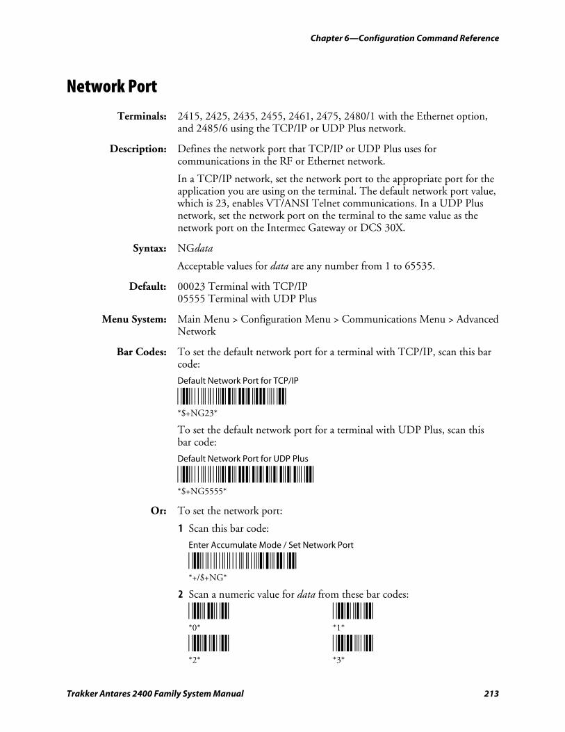
Chapter 6—Configuration Command Reference
Trakker Antares 2400 Family System Manual 213
Network Port
Terminals: 2415, 2425, 2435, 2455, 2461, 2475, 2480/1 with the Ethernet option, and 2485/6 using the TCP/IP or UDP Plus network.
Description: Defines the network port that TCP/IP or UDP Plus uses for communications in the RF or Ethernet network.
In a TCP/IP network, set the network port to the appropriate port for the application you are using on the terminal. The default network port value, which is 23, enables VT/ANSI Telnet communications. In a UDP Plus network, set the network port on the terminal to the same value as the network port on the Intermec Gateway or DCS 30X.
Syntax: NGdata
Acceptable values for data are any number from 1 to 65535.
Default: 00023 Terminal with TCP/IP 05555 Terminal with UDP Plus
Menu System: Main Menu > Configuration Menu > Communications Menu > Advanced Network
Bar Codes: To set the default network port for a terminal with TCP/IP, scan this bar code:
Default Network Port for TCP/IP
*$+NG23* *$+NG23*
To set the default network port for a terminal with UDP Plus, scan this bar code:
Default Network Port for UDP Plus
*$+NG5555* *$+NG5555*
Or: To set the network port:
1 Scan this bar code:
Enter Accumulate Mode / Set Network Port
*+/$+NG* *+/$+NG*
2 Scan a numeric value for data from these bar codes:
*0* *1* *0* *1*
*2* *3* *2* *3*
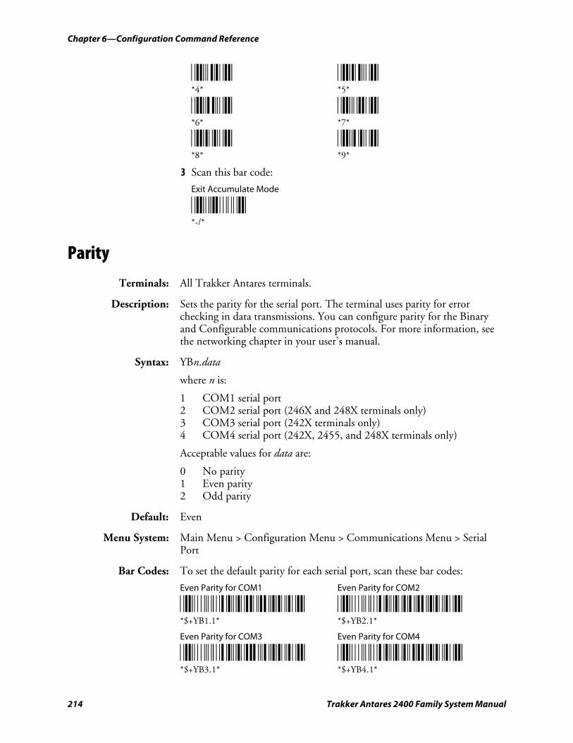
Chapter 6—Configuration Command Reference
214 Trakker Antares 2400 Family System Manual
*4* *5* *4* *5*
*6* *7* *6* *7*
*8* *9* *8* *9*
3 Scan this bar code:
Exit Accumulate Mode
*-/* *-/*
Parity
Terminals: All Trakker Antares terminals.
Description: Sets the parity for the serial port. The terminal uses parity for error checking in data transmissions. You can configure parity for the Binary and Configurable communications protocols. For more information, see the networking chapter in your user’s manual.
Syntax: YBn.data
where n is:
1 COM1 serial port 2 COM2 serial port (246X and 248X terminals only) 3 COM3 serial port (242X terminals only) 4 COM4 serial port (242X, 2455, and 248X terminals only)
Acceptable values for data are:
0 No parity 1 Even parity 2 Odd parity
Default: Even
Menu System: Main Menu > Configuration Menu > Communications Menu > Serial Port
Bar Codes: To set the default parity for each serial port, scan these bar codes:
Even Parity for COM1 Even Parity for COM2
*$+YB1.1* *$+YB2.1* *$+YB1.1* *$+YB2.1*
Even Parity for COM3 Even Parity for COM4
*$+YB3.1* *$+YB4.1* *$+YB3.1* *$+YB4.1*
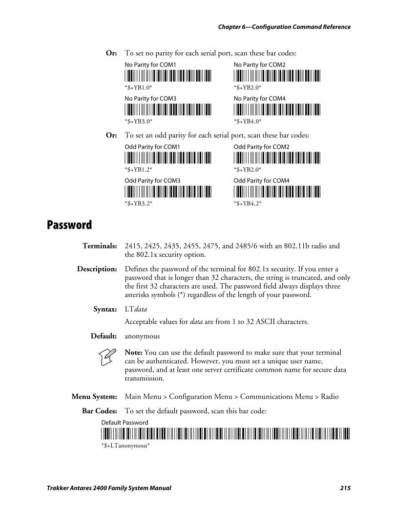
Chapter 6—Configuration Command Reference
Trakker Antares 2400 Family System Manual 215
Or: To set no parity for each serial port, scan these bar codes:
No Parity for COM1 No Parity for COM2
*$+YB1.0* *$+YB2.0* *$+YB1.0* *$+YB2.0*
No Parity for COM3 No Parity for COM4
*$+YB3.0* *$+YB4.0* *$+YB3.0* *$+YB4.0*
Or: To set an odd parity for each serial port, scan these bar codes:
Odd Parity for COM1 Odd Parity for COM2
*$+YB1.2* *$+YB2.2* *$+YB1.2* *$+YB2.0*
Odd Parity for COM3 Odd Parity for COM4
*$+YB3.2* *$+YB4.2* *$+YB3.2* *$+YB4.2*
Password
Terminals: 2415, 2425, 2435, 2455, 2475, and 2485/6 with an 802.11b radio and the 802.1x security option.
Description: Defines the password of the terminal for 802.1x security. If you enter a password that is longer than 32 characters, the string is truncated, and only the first 32 characters are used. The password field always displays three asterisks symbols (*) regardless of the length of your password.
Syntax: LTdata
Acceptable values for data are from 1 to 32 ASCII characters.
Default: anonymous
Note: You can use the default password to make sure that your terminal can be authenticated. However, you must set a unique user name, password, and at least one server certificate common name for secure data transmission.
Menu System: Main Menu > Configuration Menu > Communications Menu > Radio
Bar Codes: To set the default password, scan this bar code:
Default Password
*/D/KLT+A+N+O+N+Y+M+O+U+S* *$+LTanonymous*
Chapter 6—Configuration Command Reference
216 Trakker Antares 2400 Family System Manual
Or: To set the password to an ASCII character string:
Note: To set this command using the bar code labels from the “Full ASCII Bar Code Chart” on page 284, you must configure the terminal to use Code 39 in Full ASCII mode. For help, see “Code 39” on page 146.
1 Scan this bar code:
Enter Accumulate Mode / Set Password
*+/$+LT* *+/$+LT*
2 Scan a value for data from the “Full ASCII Bar Code Chart” on page 284. The password can be from 1 to 32 characters.
3 Scan this bar code:
Exit Accumulate Mode
*-/* *-/*
PDF417
Terminals: 241X, 242X, and 243X terminals with a PDF417 scanner.
Description: The PDF417 symbology is a stacked 2D symbology that allows you to scan across rows of code. Each row consists of start/stop characters, row identifiers, and symbol characters, which consist of four bars and four spaces each and contain the actual data. This symbology uses error correction symbol characters appended at the end to recover loss of data.
Note: PDF417 is a decoded bar code symbology and requires at least one data value in a bar code. Therefore, if the terminal is configured to scan decoded bar code symbologies, it cannot scan the Enter reader command, which only consists of a Start and Stop character and does not contain any data values.
Syntax: CQdata
Acceptable values for data are:
0 Disabled 1 Enabled
Default: Enabled
Menu System: Main Menu > Configuration Menu > Symbologies Menu
Chapter 6—Configuration Command Reference
Trakker Antares 2400 Family System Manual 217
Bar Codes: Scan one of these bar codes:
Disable PDF417 Enable PDF417
*$+CQ0* *$+CQ1* *$+CQ0* *$+CQ1*
Plessey
Terminals: All Trakker Antares terminals.
Description: Enables or disables decoding of Plessey symbology. Plessey code is pulse-width modulated like most other bar codes. It includes a start character, data characters, an eight-bit cyclic check digit, a termination bar, and usually a reverse start character. The code is continuous and not self-checking. You need to configure two parameters for Plessey code: Start Code and Check Digit.
Syntax: CIdata
Acceptable values for data are:
00 Disabled 10 Plessey with reverse start code 30 Transmit check digit 31 Discard check digit
Default: Disabled
Menu System: Main Menu > Configuration Menu > Symbologies Menu > Plessey
Bar Codes: To disable Plessey:
Disable Plessey
*$+CI00* *$+CI00*
Or: To set Plessey, complete these steps:
1 Scan this bar code:
Plessey With Reverse Start Code
*$+CI10* *$+CI10*
2 Scan one of these bar codes to transmit or retain the check digit:
Transmit Check Digit Discard Check Digit
*$+CI30* *$+CI31* *$+CI30* *$+CI31*
Chapter 6—Configuration Command Reference
218 Trakker Antares 2400 Family System Manual
Poll (Polling)
Terminals: All Trakker Antares terminals.
Description: Solicits or requests data from a polled device. You can configure polling for the Configurable communications protocol. For more information, see the networking chapter in your user’s manual.
Note: Before you can enable the Poll command, you must configure the EOM and Handshake commands.
Syntax: YRn.data
where n is:
1 COM1 serial port 2 COM2 serial port (246X and 248X terminals only) 3 COM3 serial port (242X terminals only) 4 COM4 serial port (242X, 2455, and 248X terminals only)
An acceptable value for data is any ASCII character.
Disabled No characters, no polling Enabled \x1C (hexadecimal value for FS, File Separator)
Default: No characters (Disabled)
Menu System: Main Menu > Configuration Menu > Communications Menu > Serial Port
Bar Codes: To disable poll, scan one of these bar codes:
Disable Poll for COM1 Disable Poll for COM2
*$+YR1.* *$+YR2.* *$+YR1.* *$+YR2.*
Disable Poll for COM3 Disable Poll for COM4
*$+YR3.* *$+YR4.* *$+YR3.* *$+YR4.*
Or: To enable poll, scan one of these bar codes:
Note: To scan these bar code labels, you must configure the terminal to use Code 39 in Full ASCII mode. For help, see “Code 39” on page 146.
Enable Poll (Set to FS) for COM1
*/D/KYR1/N%B* *$+YR1.%B*
Enable Poll (Set to FS) for COM2
*/D/KYR2/N%B* *$+YR2.%B*
Chapter 6—Configuration Command Reference
Trakker Antares 2400 Family System Manual 219
Enable Poll (Set to FS) for COM3
*/D/KYR3/N%B* *$+YR3.%B*
Enable Poll (Set to FS) for COM4
*/D/KYR4/N%B* *$+YR4.%B*
Note: FS is encoded as %B in a Code 39 bar code label.
Postamble
Terminals: All Trakker Antares terminals.
Description: Sets the postamble that is appended to any data you scan with the terminal. Common postambles include cursor controls such as a tab or a carriage return line feed.
You can set the postamble to use characters from the extended ASCII character set such as the Field Exit code for 5250 TE. However, you cannot scan in extended ASCII characters in the Postamble command. You must use the TRAKKER Antares 2400 Menu System. For help, see “Entering ASCII Control Characters” in the configuration chapter in your user’s manual.
Syntax: AEdata
Acceptable values for data are up to 25 ASCII characters. If you are entering quotation marks as data or grouping configuration commands, you must enclose the data within quotation marks (see the example).
Note: To scan a bar code label that includes quotes, you must configure the terminal to use Code 39 in Full ASCII mode. For help, see “Code 39” on page 146.
Default: No characters (Disabled)
Menu System: Main Menu > Configuration Menu > Terminal Menu > Preamble/Postamble
Bar Codes: To disable the postamble, scan this bar code:
Disable Postamble
*$+AE* *$+AE*
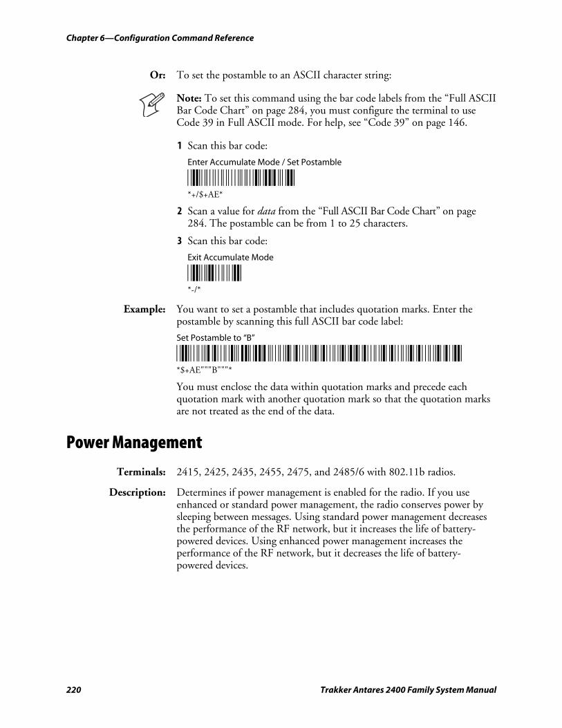
Chapter 6—Configuration Command Reference
220 Trakker Antares 2400 Family System Manual
Or: To set the postamble to an ASCII character string:
Note: To set this command using the bar code labels from the “Full ASCII Bar Code Chart” on page 284, you must configure the terminal to use Code 39 in Full ASCII mode. For help, see “Code 39” on page 146.
1 Scan this bar code:
Enter Accumulate Mode / Set Postamble
*+/$+AE* *+/$+AE*
2 Scan a value for data from the “Full ASCII Bar Code Chart” on page 284. The postamble can be from 1 to 25 characters.
3 Scan this bar code:
Exit Accumulate Mode
*-/* *-/*
Example: You want to set a postamble that includes quotation marks. Enter the postamble by scanning this full ASCII bar code label:
Set Postamble to “B”
*/D/KAE/B/B/BB/B/B/B* *$+AE"""B"""*
You must enclose the data within quotation marks and precede each quotation mark with another quotation mark so that the quotation marks are not treated as the end of the data.
Power Management
Terminals: 2415, 2425, 2435, 2455, 2475, and 2485/6 with 802.11b radios.
Description: Determines if power management is enabled for the radio. If you use enhanced or standard power management, the radio conserves power by sleeping between messages. Using standard power management decreases the performance of the RF network, but it increases the life of battery-powered devices. Using enhanced power management increases the performance of the RF network, but it decreases the life of battery-powered devices.
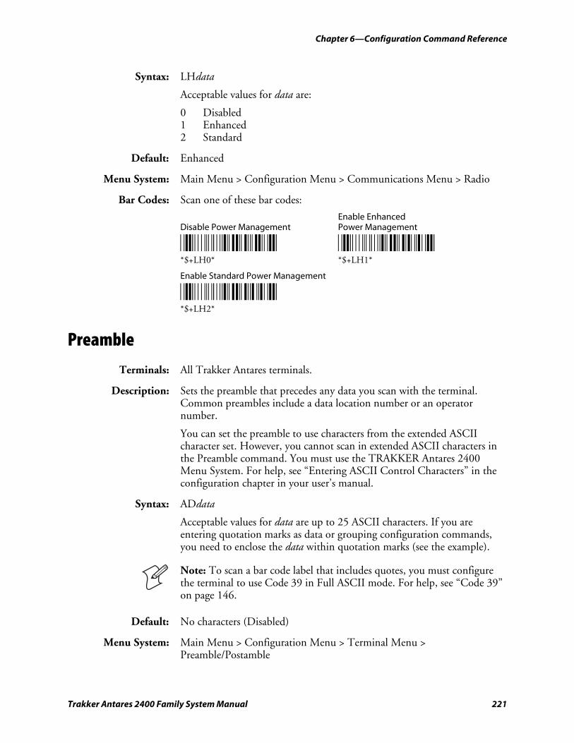
Chapter 6—Configuration Command Reference
Trakker Antares 2400 Family System Manual 221
Syntax: LHdata
Acceptable values for data are:
0 Disabled 1 Enhanced 2 Standard
Default: Enhanced
Menu System: Main Menu > Configuration Menu > Communications Menu > Radio
Bar Codes: Scan one of these bar codes:
Enable Enhanced Disable Power Management Power Management
*$+LH0* *$+LH1* *$+LH0* *$+LH1*
Enable Standard Power Management
*$+LH2* *$+LH2*
Preamble
Terminals: All Trakker Antares terminals.
Description: Sets the preamble that precedes any data you scan with the terminal. Common preambles include a data location number or an operator number.
You can set the preamble to use characters from the extended ASCII character set. However, you cannot scan in extended ASCII characters in the Preamble command. You must use the TRAKKER Antares 2400 Menu System. For help, see “Entering ASCII Control Characters” in the configuration chapter in your user’s manual.
Syntax: ADdata
Acceptable values for data are up to 25 ASCII characters. If you are entering quotation marks as data or grouping configuration commands, you need to enclose the data within quotation marks (see the example).
Note: To scan a bar code label that includes quotes, you must configure the terminal to use Code 39 in Full ASCII mode. For help, see “Code 39” on page 146.
Default: No characters (Disabled)
Menu System: Main Menu > Configuration Menu > Terminal Menu > Preamble/Postamble
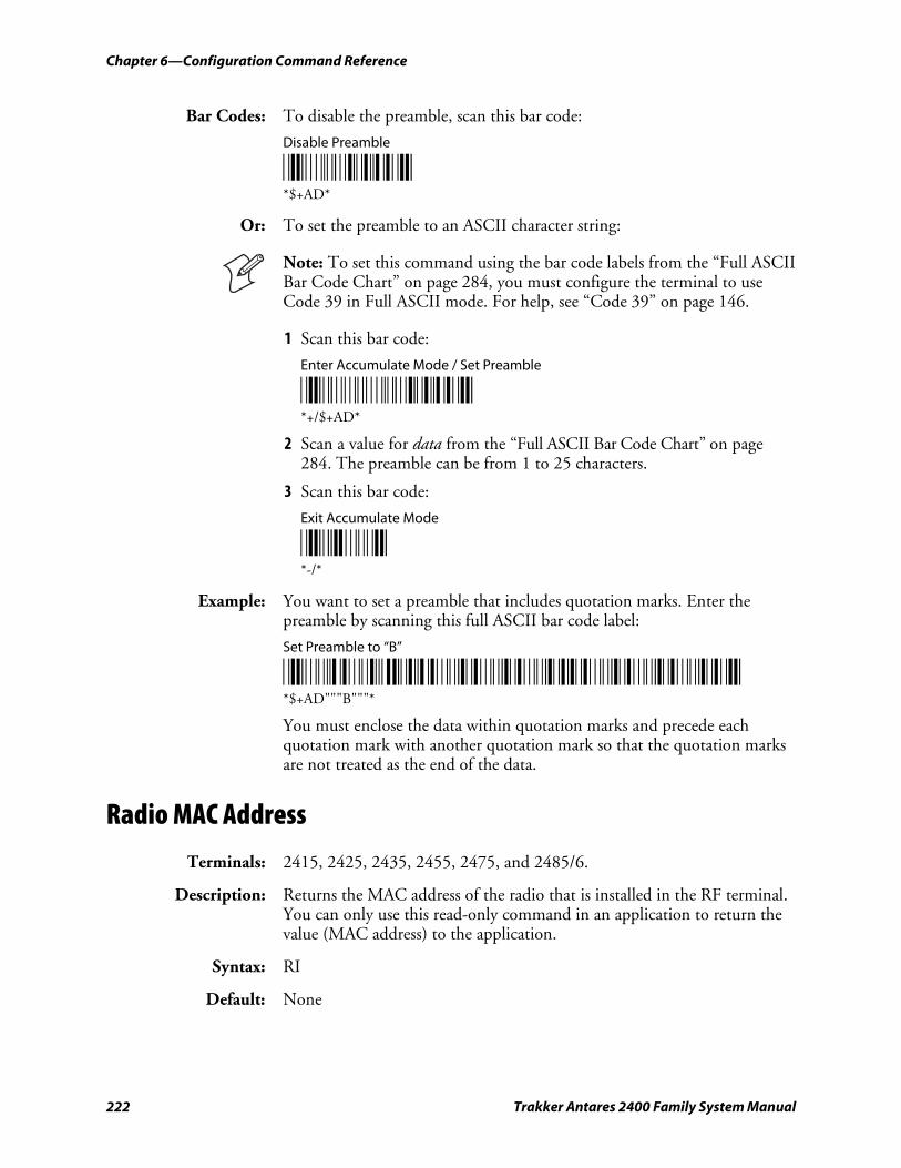
Chapter 6—Configuration Command Reference
222 Trakker Antares 2400 Family System Manual
Bar Codes: To disable the preamble, scan this bar code:
Disable Preamble
*$+AD* *$+AD*
Or: To set the preamble to an ASCII character string:
Note: To set this command using the bar code labels from the “Full ASCII Bar Code Chart” on page 284, you must configure the terminal to use Code 39 in Full ASCII mode. For help, see “Code 39” on page 146.
1 Scan this bar code:
Enter Accumulate Mode / Set Preamble
*+/$+AD* *+/$+AD*
2 Scan a value for data from the “Full ASCII Bar Code Chart” on page 284. The preamble can be from 1 to 25 characters.
3 Scan this bar code:
Exit Accumulate Mode
*-/* *-/*
Example: You want to set a preamble that includes quotation marks. Enter the preamble by scanning this full ASCII bar code label:
Set Preamble to “B”
*/D/KAD/B/B/BB/B/B/B* *$+AD"""B"""*
You must enclose the data within quotation marks and precede each quotation mark with another quotation mark so that the quotation marks are not treated as the end of the data.
Radio MAC Address
Terminals: 2415, 2425, 2435, 2455, 2475, and 2485/6.
Description: Returns the MAC address of the radio that is installed in the RF terminal. You can only use this read-only command in an application to return the value (MAC address) to the application.
Syntax: RI
Default: None
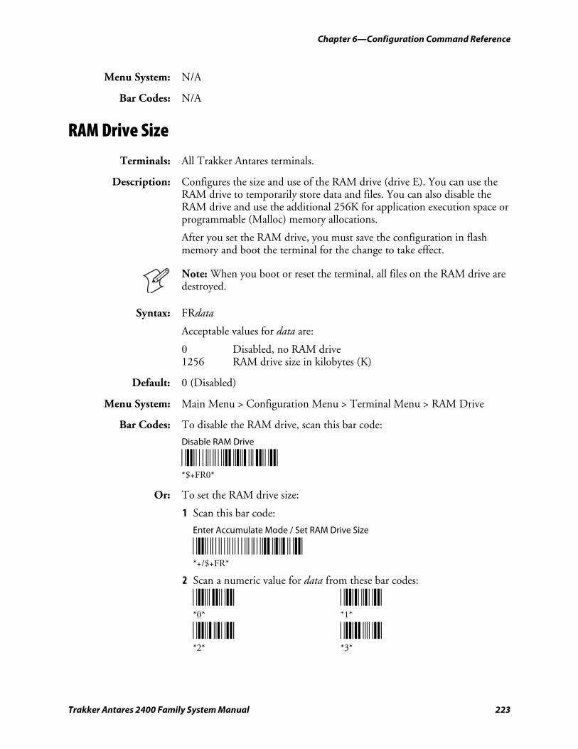
Chapter 6—Configuration Command Reference
Trakker Antares 2400 Family System Manual 223
Menu System: N/A
Bar Codes: N/A
RAM Drive Size
Terminals: All Trakker Antares terminals.
Description: Configures the size and use of the RAM drive (drive E). You can use the RAM drive to temporarily store data and files. You can also disable the RAM drive and use the additional 256K for application execution space or programmable (Malloc) memory allocations.
After you set the RAM drive, you must save the configuration in flash memory and boot the terminal for the change to take effect.
Note: When you boot or reset the terminal, all files on the RAM drive are destroyed.
Syntax: FRdata
Acceptable values for data are:
0 Disabled, no RAM drive 1256 RAM drive size in kilobytes (K)
Default: 0 (Disabled)
Menu System: Main Menu > Configuration Menu > Terminal Menu > RAM Drive
Bar Codes: To disable the RAM drive, scan this bar code:
Disable RAM Drive
*$+FR0* *$+FR0*
Or: To set the RAM drive size:
1 Scan this bar code:
Enter Accumulate Mode / Set RAM Drive Size
*+/$+FR* *+/$+FR*
2 Scan a numeric value for data from these bar codes:
*0* *1* *0* *1*
*2* *3* *2* *3*
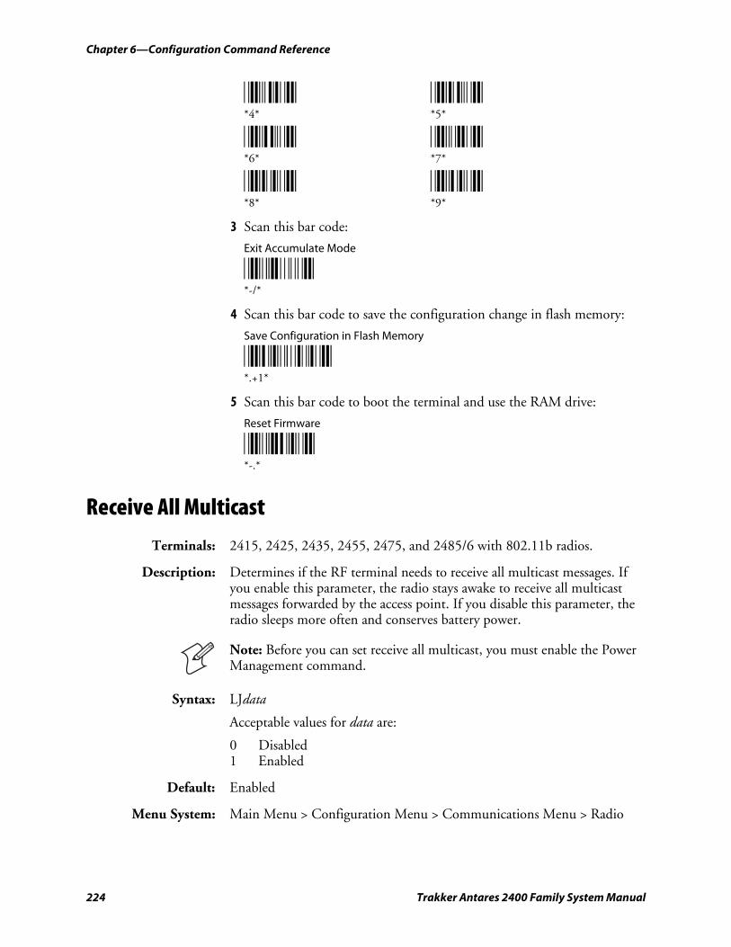
Chapter 6—Configuration Command Reference
224 Trakker Antares 2400 Family System Manual
*4* *5* *4* *5*
*6* *7* *6* *7*
*8* *9* *8* *9*
3 Scan this bar code:
Exit Accumulate Mode
*-/* *-/*
4 Scan this bar code to save the configuration change in flash memory:
Save Configuration in Flash Memory
*.+1* *.+1*
5 Scan this bar code to boot the terminal and use the RAM drive:
Reset Firmware
*-.* *-.*
Receive All Multicast
Terminals: 2415, 2425, 2435, 2455, 2475, and 2485/6 with 802.11b radios.
Description: Determines if the RF terminal needs to receive all multicast messages. If you enable this parameter, the radio stays awake to receive all multicast messages forwarded by the access point. If you disable this parameter, the radio sleeps more often and conserves battery power.
Note: Before you can set receive all multicast, you must enable the Power Management command.
Syntax: LJdata
Acceptable values for data are:
0 Disabled 1 Enabled
Default: Enabled
Menu System: Main Menu > Configuration Menu > Communications Menu > Radio
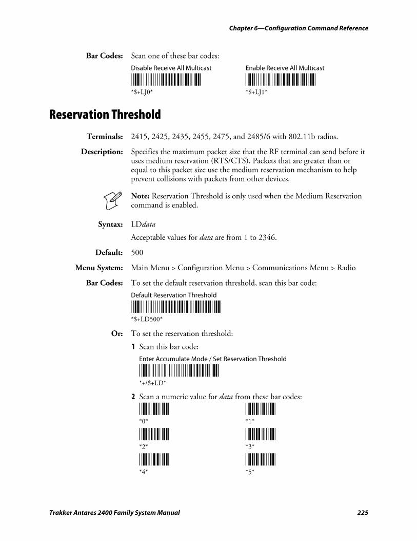
Chapter 6—Configuration Command Reference
Trakker Antares 2400 Family System Manual 225
Bar Codes: Scan one of these bar codes:
Disable Receive All Multicast Enable Receive All Multicast
*$+LJ0* *$+LJ1* *$+LJ0* *$+LJ1*
Reservation Threshold
Terminals: 2415, 2425, 2435, 2455, 2475, and 2485/6 with 802.11b radios.
Description: Specifies the maximum packet size that the RF terminal can send before it uses medium reservation (RTS/CTS). Packets that are greater than or equal to this packet size use the medium reservation mechanism to help prevent collisions with packets from other devices.
Note: Reservation Threshold is only used when the Medium Reservation command is enabled.
Syntax: LDdata
Acceptable values for data are from 1 to 2346.
Default: 500
Menu System: Main Menu > Configuration Menu > Communications Menu > Radio
Bar Codes: To set the default reservation threshold, scan this bar code:
Default Reservation Threshold
*$+LD500* *$+LD500*
Or: To set the reservation threshold:
1 Scan this bar code:
Enter Accumulate Mode / Set Reservation Threshold
*+/$+LD* *+/$+LD*
2 Scan a numeric value for data from these bar codes:
*0* *1* *0* *1*
*2* *3* *2* *3*
*4* *5* *4* *5*
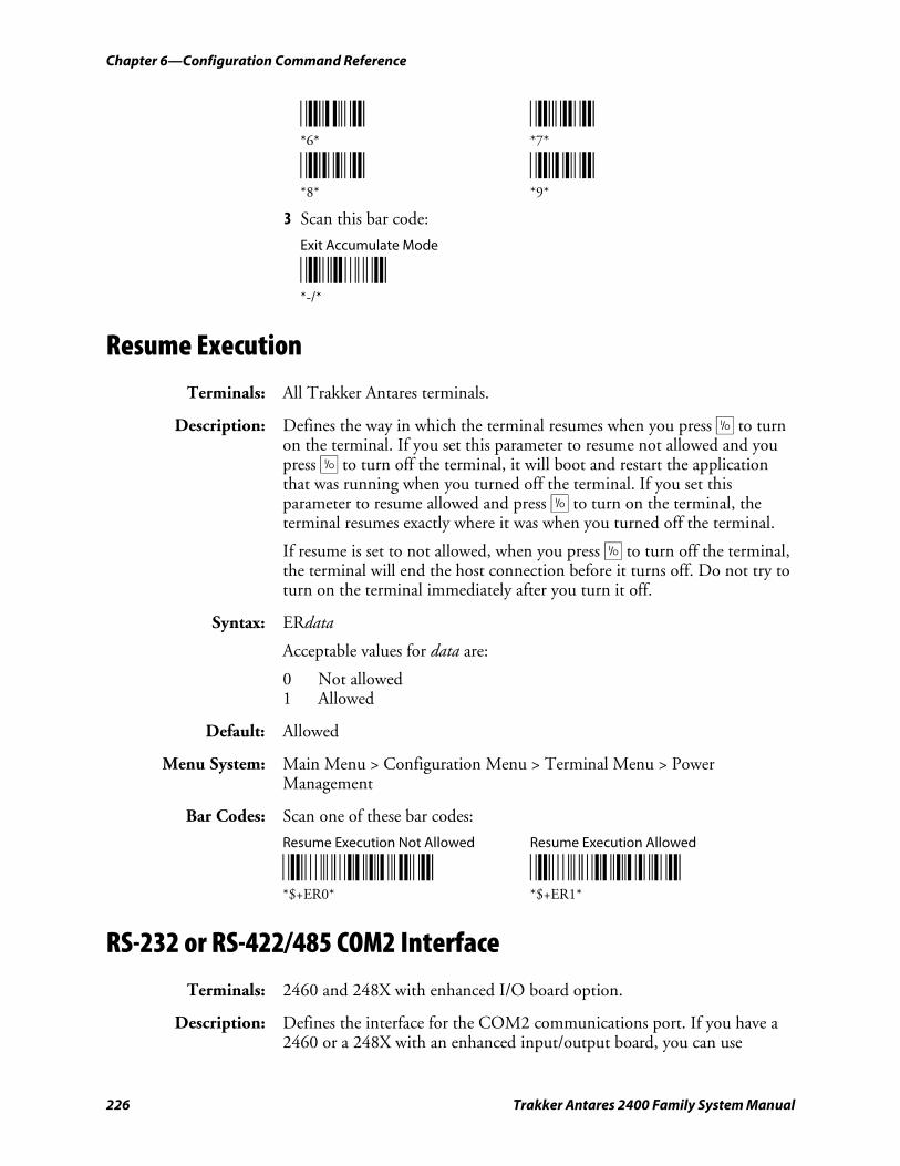
Chapter 6—Configuration Command Reference
226 Trakker Antares 2400 Family System Manual
*6* *7* *6* *7*
*8* *9* *8* *9*
3 Scan this bar code:
Exit Accumulate Mode
*-/* *-/*
Resume Execution
Terminals: All Trakker Antares terminals.
Description: Defines the way in which the terminal resumes when you press œ to turn on the terminal. If you set this parameter to resume not allowed and you press œ to turn off the terminal, it will boot and restart the application that was running when you turned off the terminal. If you set this parameter to resume allowed and press œ to turn on the terminal, the terminal resumes exactly where it was when you turned off the terminal.
If resume is set to not allowed, when you press œ to turn off the terminal, the terminal will end the host connection before it turns off. Do not try to turn on the terminal immediately after you turn it off.
Syntax: ERdata
Acceptable values for data are:
0 Not allowed 1 Allowed
Default: Allowed
Menu System: Main Menu > Configuration Menu > Terminal Menu > Power Management
Bar Codes: Scan one of these bar codes:
Resume Execution Not Allowed Resume Execution Allowed
*$+ER0* *$+ER1* *$+ER0* *$+ER1*
RS-232 or RS-422/485 COM2 Interface
Terminals: 2460 and 248X with enhanced I/O board option.
Description: Defines the interface for the COM2 communications port. If you have a 2460 or a 248X with an enhanced input/output board, you can use
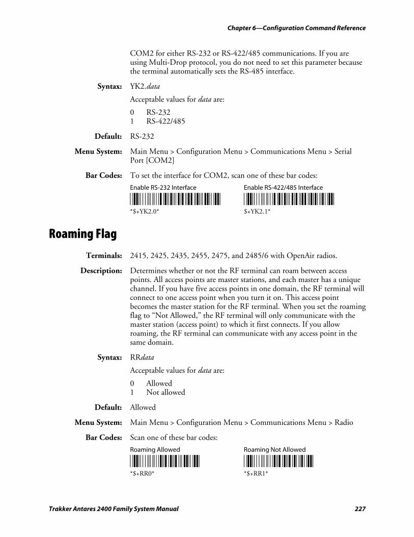
Chapter 6—Configuration Command Reference
Trakker Antares 2400 Family System Manual 227
COM2 for either RS-232 or RS-422/485 communications. If you are using Multi-Drop protocol, you do not need to set this parameter because the terminal automatically sets the RS-485 interface.
Syntax: YK2.data
Acceptable values for data are:
0 RS-232 1 RS-422/485
Default: RS-232
Menu System: Main Menu > Configuration Menu > Communications Menu > Serial Port [COM2]
Bar Codes: To set the interface for COM2, scan one of these bar codes:
Enable RS-232 Interface Enable RS-422/485 Interface
*$+YK2.0* *$+YK2.1* *$+YK2.0* $+YK2.1*
Roaming Flag
Terminals: 2415, 2425, 2435, 2455, 2475, and 2485/6 with OpenAir radios.
Description: Determines whether or not the RF terminal can roam between access points. All access points are master stations, and each master has a unique channel. If you have five access points in one domain, the RF terminal will connect to one access point when you turn it on. This access point becomes the master station for the RF terminal. When you set the roaming flag to “Not Allowed,” the RF terminal will only communicate with the master station (access point) to which it first connects. If you allow roaming, the RF terminal can communicate with any access point in the same domain.
Syntax: RRdata
Acceptable values for data are:
0 Allowed 1 Not allowed
Default: Allowed
Menu System: Main Menu > Configuration Menu > Communications Menu > Radio
Bar Codes: Scan one of these bar codes:
Roaming Allowed Roaming Not Allowed
*$+RR0* *$+RR1* *$+RR0* *$+RR1*
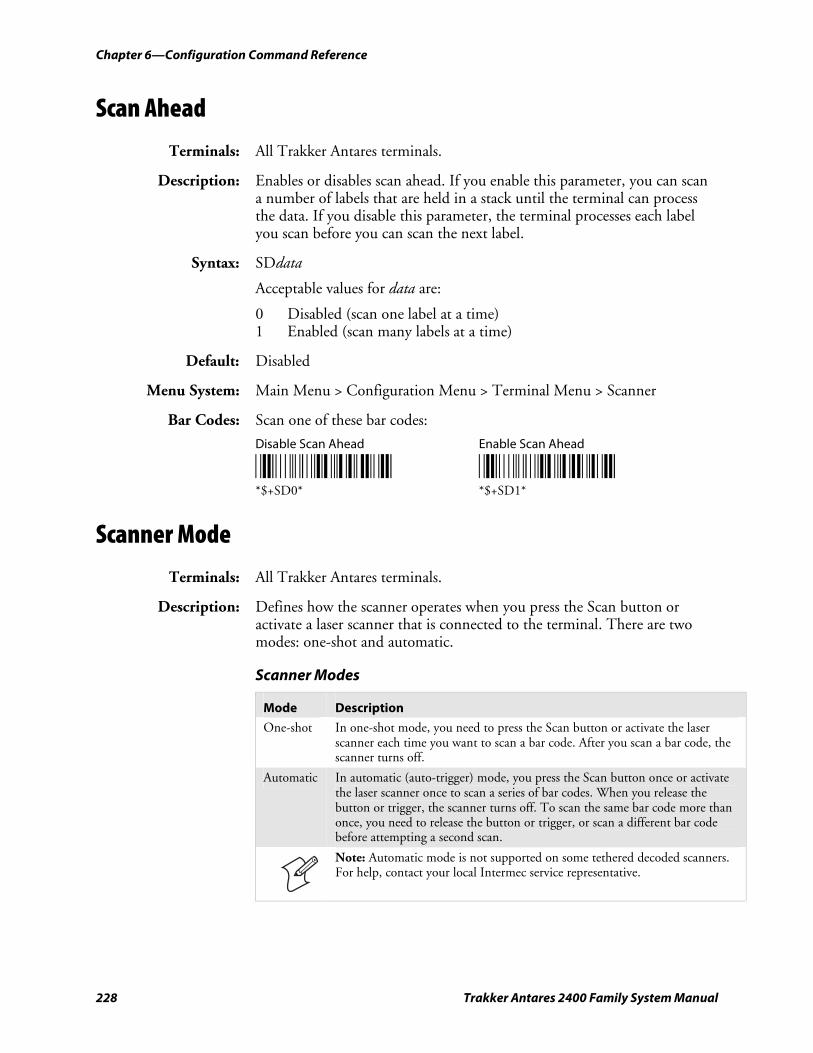
Chapter 6—Configuration Command Reference
228 Trakker Antares 2400 Family System Manual
Scan Ahead
Terminals: All Trakker Antares terminals.
Description: Enables or disables scan ahead. If you enable this parameter, you can scan a number of labels that are held in a stack until the terminal can process the data. If you disable this parameter, the terminal processes each label you scan before you can scan the next label.
Syntax: SDdata
Acceptable values for data are:
0 Disabled (scan one label at a time) 1 Enabled (scan many labels at a time)
Default: Disabled
Menu System: Main Menu > Configuration Menu > Terminal Menu > Scanner
Bar Codes: Scan one of these bar codes:
Disable Scan Ahead Enable Scan Ahead
*$+SD0* *$+SD1* *$+SD0* *$+SD1*
Scanner Mode
Terminals: All Trakker Antares terminals.
Description: Defines how the scanner operates when you press the Scan button or activate a laser scanner that is connected to the terminal. There are two modes: one-shot and automatic.
Scanner Modes
Mode Description
One-shot In one-shot mode, you need to press the Scan button or activate the laser scanner each time you want to scan a bar code. After you scan a bar code, the scanner turns off.
Automatic In automatic (auto-trigger) mode, you press the Scan button once or activate the laser scanner once to scan a series of bar codes. When you release the button or trigger, the scanner turns off. To scan the same bar code more than once, you need to release the button or trigger, or scan a different bar code before attempting a second scan.
Note: Automatic mode is not supported on some tethered decoded scanners. For help, contact your local Intermec service representative.
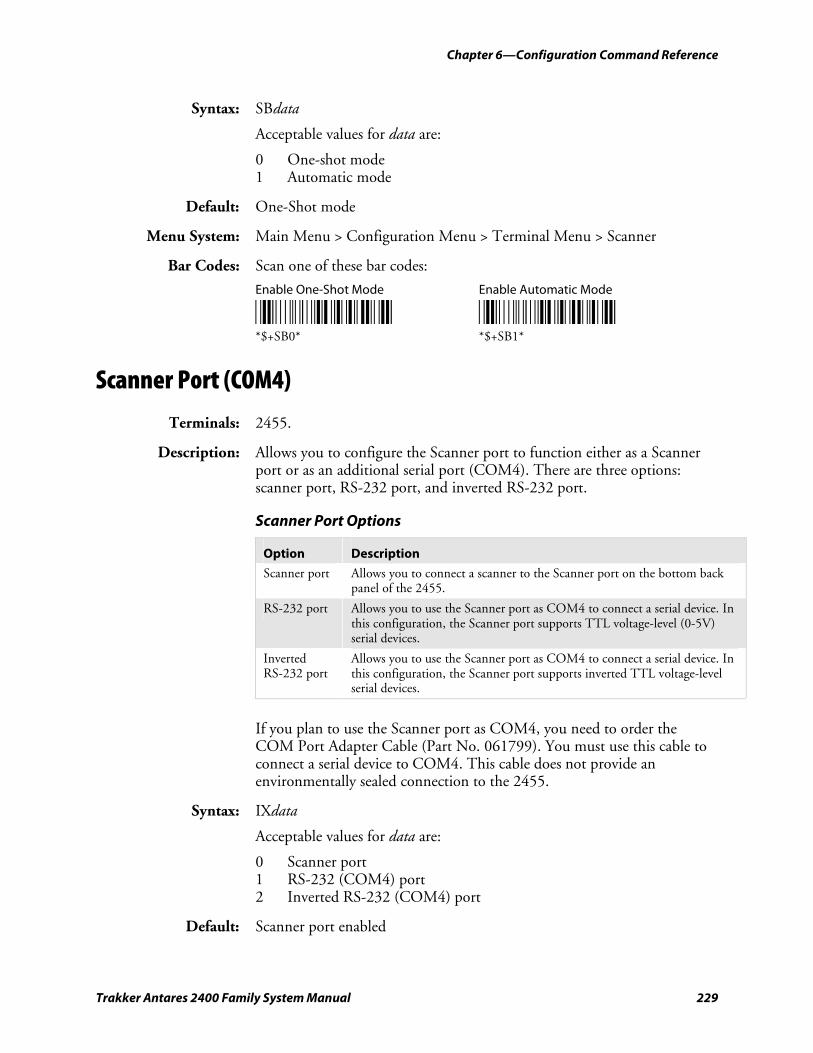
Chapter 6—Configuration Command Reference
Trakker Antares 2400 Family System Manual 229
Syntax: SBdata
Acceptable values for data are:
0 One-shot mode 1 Automatic mode
Default: One-Shot mode
Menu System: Main Menu > Configuration Menu > Terminal Menu > Scanner
Bar Codes: Scan one of these bar codes:
Enable One-Shot Mode Enable Automatic Mode
*$+SB0* *$+SB1* *$+SB0* *$+SB1*
Scanner Port (COM4)
Terminals: 2455.
Description: Allows you to configure the Scanner port to function either as a Scanner port or as an additional serial port (COM4). There are three options: scanner port, RS-232 port, and inverted RS-232 port.
Scanner Port Options
Option Description
Scanner port Allows you to connect a scanner to the Scanner port on the bottom back panel of the 2455.
RS-232 port Allows you to use the Scanner port as COM4 to connect a serial device. In this configuration, the Scanner port supports TTL voltage-level (0-5V) serial devices.
Inverted RS-232 port
Allows you to use the Scanner port as COM4 to connect a serial device. In this configuration, the Scanner port supports inverted TTL voltage-level serial devices.
If you plan to use the Scanner port as COM4, you need to order the COM Port Adapter Cable (Part No. 061799). You must use this cable to connect a serial device to COM4. This cable does not provide an environmentally sealed connection to the 2455.
Syntax: IXdata
Acceptable values for data are:
0 Scanner port 1 RS-232 (COM4) port 2 Inverted RS-232 (COM4) port
Default: Scanner port enabled
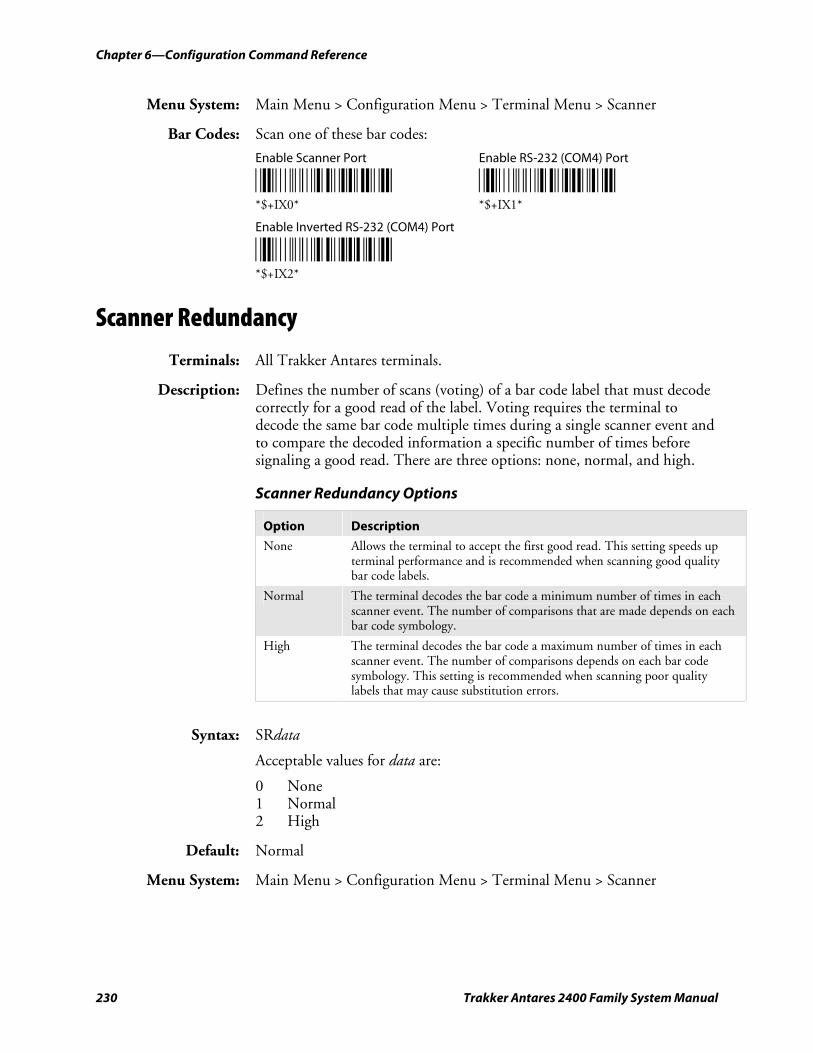
Chapter 6—Configuration Command Reference
230 Trakker Antares 2400 Family System Manual
Menu System: Main Menu > Configuration Menu > Terminal Menu > Scanner
Bar Codes: Scan one of these bar codes:
Enable Scanner Port Enable RS-232 (COM4) Port
*$+IX0* *$+IX1* *$+IX0* *$+IX1*
Enable Inverted RS-232 (COM4) Port
*$+IX2* *$+IX2*
Scanner Redundancy
Terminals: All Trakker Antares terminals.
Description: Defines the number of scans (voting) of a bar code label that must decode correctly for a good read of the label. Voting requires the terminal to decode the same bar code multiple times during a single scanner event and to compare the decoded information a specific number of times before signaling a good read. There are three options: none, normal, and high.
Scanner Redundancy Options
Option Description
None Allows the terminal to accept the first good read. This setting speeds up terminal performance and is recommended when scanning good quality bar code labels.
Normal The terminal decodes the bar code a minimum number of times in each scanner event. The number of comparisons that are made depends on each bar code symbology.
High The terminal decodes the bar code a maximum number of times in each scanner event. The number of comparisons depends on each bar code symbology. This setting is recommended when scanning poor quality labels that may cause substitution errors.
Syntax: SRdata
Acceptable values for data are:
0 None 1 Normal 2 High
Default: Normal
Menu System: Main Menu > Configuration Menu > Terminal Menu > Scanner
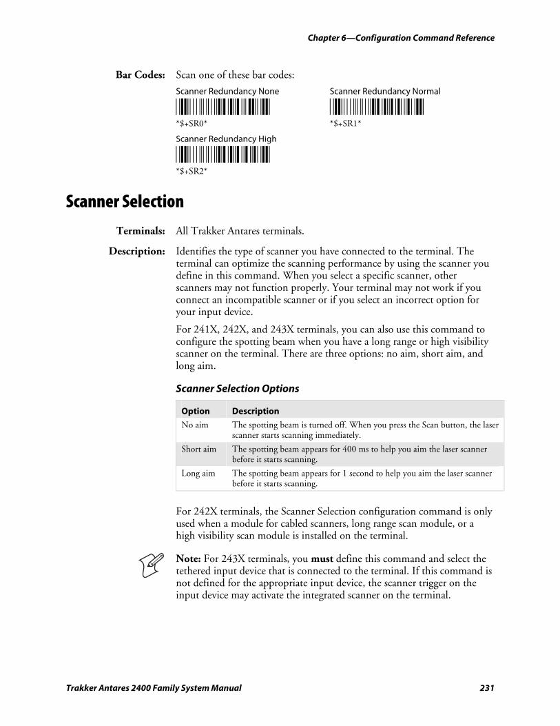
Chapter 6—Configuration Command Reference
Trakker Antares 2400 Family System Manual 231
Bar Codes: Scan one of these bar codes:
Scanner Redundancy None Scanner Redundancy Normal
*$+SR0* *$+SR1* *$+SR0* *$+SR1*
Scanner Redundancy High
*$+SR2* *$+SR2*
Scanner Selection
Terminals: All Trakker Antares terminals.
Description: Identifies the type of scanner you have connected to the terminal. The terminal can optimize the scanning performance by using the scanner you define in this command. When you select a specific scanner, other scanners may not function properly. Your terminal may not work if you connect an incompatible scanner or if you select an incorrect option for your input device.
For 241X, 242X, and 243X terminals, you can also use this command to configure the spotting beam when you have a long range or high visibility scanner on the terminal. There are three options: no aim, short aim, and long aim.
Scanner Selection Options
Option Description
No aim The spotting beam is turned off. When you press the Scan button, the laser scanner starts scanning immediately.
Short aim The spotting beam appears for 400 ms to help you aim the laser scanner before it starts scanning.
Long aim The spotting beam appears for 1 second to help you aim the laser scanner before it starts scanning.
For 242X terminals, the Scanner Selection configuration command is only used when a module for cabled scanners, long range scan module, or a high visibility scan module is installed on the terminal.
Note: For 243X terminals, you must define this command and select the tethered input device that is connected to the terminal. If this command is not defined for the appropriate input device, the scanner trigger on the input device may activate the integrated scanner on the terminal.
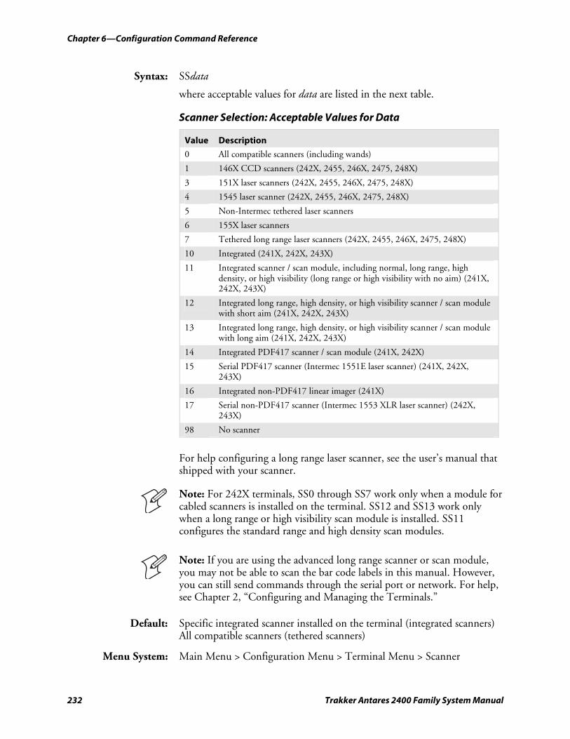
Chapter 6—Configuration Command Reference
232 Trakker Antares 2400 Family System Manual
Syntax: SSdata
where acceptable values for data are listed in the next table.
Scanner Selection: Acceptable Values for Data
Value Description
0 All compatible scanners (including wands)
1 146X CCD scanners (242X, 2455, 246X, 2475, 248X)
3 151X laser scanners (242X, 2455, 246X, 2475, 248X)
4 1545 laser scanner (242X, 2455, 246X, 2475, 248X)
5 Non-Intermec tethered laser scanners
6 155X laser scanners
7 Tethered long range laser scanners (242X, 2455, 246X, 2475, 248X)
10 Integrated (241X, 242X, 243X)
11 Integrated scanner / scan module, including normal, long range, high density, or high visibility (long range or high visibility with no aim) (241X, 242X, 243X)
12 Integrated long range, high density, or high visibility scanner / scan module with short aim (241X, 242X, 243X)
13 Integrated long range, high density, or high visibility scanner / scan module with long aim (241X, 242X, 243X)
14 Integrated PDF417 scanner / scan module (241X, 242X)
15 Serial PDF417 scanner (Intermec 1551E laser scanner) (241X, 242X, 243X)
16 Integrated non-PDF417 linear imager (241X)
17 Serial non-PDF417 scanner (Intermec 1553 XLR laser scanner) (242X, 243X)
98 No scanner
For help configuring a long range laser scanner, see the user’s manual that shipped with your scanner.
Note: For 242X terminals, SS0 through SS7 work only when a module for cabled scanners is installed on the terminal. SS12 and SS13 work only when a long range or high visibility scan module is installed. SS11 configures the standard range and high density scan modules.
Note: If you are using the advanced long range scanner or scan module, you may not be able to scan the bar code labels in this manual. However, you can still send commands through the serial port or network. For help, see Chapter 2, “Configuring and Managing the Terminals.”
Default: Specific integrated scanner installed on the terminal (integrated scanners) All compatible scanners (tethered scanners)
Menu System: Main Menu > Configuration Menu > Terminal Menu > Scanner
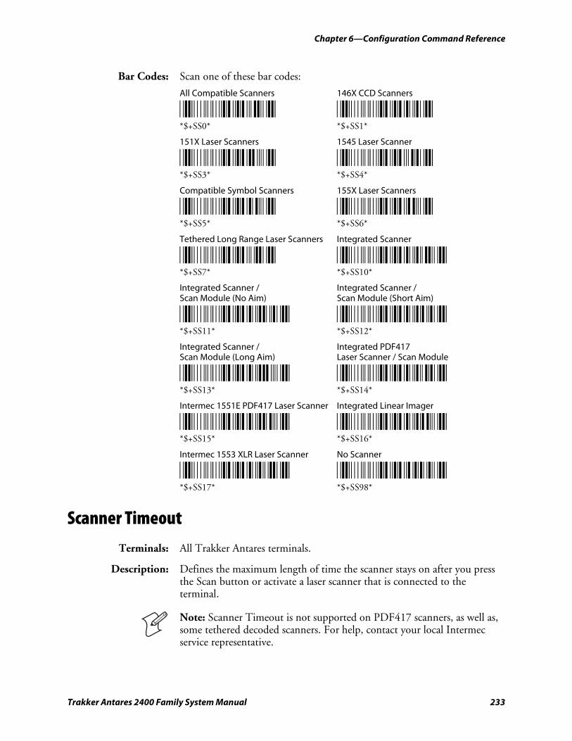
Chapter 6—Configuration Command Reference
Trakker Antares 2400 Family System Manual 233
Bar Codes: Scan one of these bar codes:
All Compatible Scanners 146X CCD Scanners
*$+SS0* *$+SS1* *$+SS0* *$+SS1*
151X Laser Scanners 1545 Laser Scanner
*$+SS3* *$+SS4* *$+SS3* *$+SS4*
Compatible Symbol Scanners 155X Laser Scanners
*$+SS5* *$+SS6* *$+SS5* *$+SS6*
Tethered Long Range Laser Scanners Integrated Scanner
*$+SS7* *$+SS10* *$+SS7* *$+SS10*
Integrated Scanner / Integrated Scanner / Scan Module (No Aim) Scan Module (Short Aim)
*$+SS11* *$+SS12* *$+SS11* *$+SS12*
Integrated Scanner / Integrated PDF417 Scan Module (Long Aim) Laser Scanner / Scan Module
*$+SS13* *$+SS14* *$+SS13* *$+SS14*
Intermec 1551E PDF417 Laser Scanner Integrated Linear Imager
*$+SS15* *$+SS16* *$+SS15* *$+SS16*
Intermec 1553 XLR Laser Scanner No Scanner
*$+SS17* *$+SS98* *$+SS17* *$+SS98*
Scanner Timeout
Terminals: All Trakker Antares terminals.
Description: Defines the maximum length of time the scanner stays on after you press the Scan button or activate a laser scanner that is connected to the terminal.
Note: Scanner Timeout is not supported on PDF417 scanners, as well as, some tethered decoded scanners. For help, contact your local Intermec service representative.
Chapter 6—Configuration Command Reference
234 Trakker Antares 2400 Family System Manual
Syntax: SAdata
Acceptable values for data are:
0 Disabled 1-60 Shutoff time in seconds 3-60 Shutoff time in seconds (decoded scanners with Scanner Trigger set to pulse triggering)
Note: If you are using a decoded scanner, the scanner defaults to a timeout of 3 seconds. The menu system may display the default scanner timeout value of Disabled, however, the actual timeout is 3 seconds. Do not try to set the scanner timeout to Disabled.
Default: Disabled (no timeout)
Menu System: Main Menu > Configuration Menu > Terminal Menu > Scanner
Bar Codes: To set the default scanner timeout, scan this bar code:
Disable Scanner Timeout
*$+SA0* *$+SA0*
Or: To set the scanner timeout:
1 Scan this bar code:
Enter Accumulate Mode / Set Scanner Timeout
*+/$+SA* *+/$+SA*
2 Scan a numeric value for data from these bar codes:
*0* *1* *0* *1*
*2* *3* *2* *3*
*4* *5* *4* *5*
*6* *7* *6* *7*
*8* *9* *8* *9*
3 Scan this bar code:
Exit Accumulate Mode
*-/* *-/*
Chapter 6—Configuration Command Reference
Trakker Antares 2400 Family System Manual 235
Scanner Trigger
Terminals: All Trakker Antares terminals.
Description: Scanner trigger allows you to set level triggering and either edge or pulse triggering depending on the type of scanner you are using. There are three triggering options: level, edge, and pulse.
Scanner Trigger Options
Option Description
Level triggering
Level triggering is available on terminals using either decoded or non-decoded scanners. With level triggering, when you activate the scanner, the laser turns on and stays on until you release the trigger on the laser scanner.
Edge triggering
Edge triggering is available on terminals using non-decoded scanners. With edge triggering, when you activate the scanner, the laser turns on and stays on. When you activate the scanner a second time, the laser turns off. Simply releasing the button or trigger does not turn off the laser. If the laser is left on, the scanner timeout turns the laser off.
Pulse triggering
Pulse triggering is supported on 241X terminals using the integrated PDF417 scanner or linear imager and on 242X terminals using the PDF417 scan module. With pulse triggering, when you activate the scanner, the laser turns on. The laser remains on until the scanner timeout turns the laser off. If the scanner timeout is set to 0, the laser turns off after 3 seconds.
Note: Earlier versions of PDF417 scanners do not support pulse triggering. For help upgrading your scanner, contact your local Intermec service representative.
Syntax: SCdata
Acceptable values for data are:
0 Level triggering 1 Edge or Pulse triggering
Default: Level triggering
Menu System: Main Menu > Configuration Menu > Terminal Menu > Scanner
Bar Codes: Scan one of these bar codes:
Enable Level Triggering Enable Edge or Pulse Triggering
*$+SC0* *$+SC1* *$+SC0* *$+SC1*
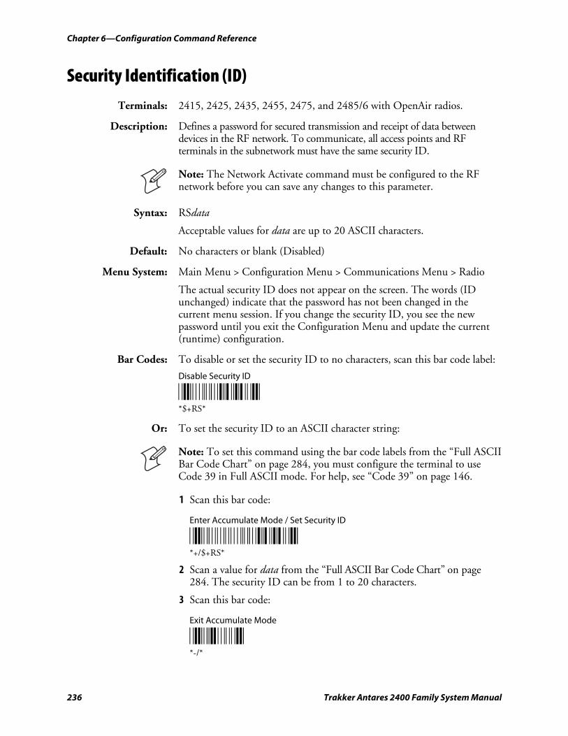
Chapter 6—Configuration Command Reference
236 Trakker Antares 2400 Family System Manual
Security Identification (ID)
Terminals: 2415, 2425, 2435, 2455, 2475, and 2485/6 with OpenAir radios.
Description: Defines a password for secured transmission and receipt of data between devices in the RF network. To communicate, all access points and RF terminals in the subnetwork must have the same security ID.
Note: The Network Activate command must be configured to the RF network before you can save any changes to this parameter.
Syntax: RSdata
Acceptable values for data are up to 20 ASCII characters.
Default: No characters or blank (Disabled)
Menu System: Main Menu > Configuration Menu > Communications Menu > Radio
The actual security ID does not appear on the screen. The words (ID unchanged) indicate that the password has not been changed in the current menu session. If you change the security ID, you see the new password until you exit the Configuration Menu and update the current (runtime) configuration.
Bar Codes: To disable or set the security ID to no characters, scan this bar code label:
Disable Security ID
*$+RS* *$+RS*
Or: To set the security ID to an ASCII character string:
Note: To set this command using the bar code labels from the “Full ASCII Bar Code Chart” on page 284, you must configure the terminal to use Code 39 in Full ASCII mode. For help, see “Code 39” on page 146.
1 Scan this bar code:
Enter Accumulate Mode / Set Security ID
*+/$+RS* *+/$+RS*
2 Scan a value for data from the “Full ASCII Bar Code Chart” on page 284. The security ID can be from 1 to 20 characters.
3 Scan this bar code:
Exit Accumulate Mode
*-/* *-/*

Chapter 6—Configuration Command Reference
Trakker Antares 2400 Family System Manual 237
Serial Port Protocol
Terminals: All Trakker Antares terminals.
Description: Allows you to set the protocol that the serial port uses to communicate with the connected device. Communications protocols determine exactly how data is transmitted between the terminal and the serial device. Each protocol has parameters you can set, such as baud rate and parity. Both the terminal and the serial device must use the same protocol and parameter settings to communicate properly.
The terminal can communicate in these five protocols:
• Binary
• Configurable protocol
• Master Polling
• Multi-Drop (COM2 only)
• Polling Mode D
Additionally, you can simulate Point-to-Point protocol by modifying the Configurable protocol. Each protocol is described in the networking chapter in your user’s manual.
Syntax: YUn.data
where n is:
1 COM1 serial port 2 COM2 serial port (246X and 248X terminals only) 3 COM3 serial port (242X terminals only) 4 COM4 serial port (242X, 2455, and 248X terminals only)
Acceptable values for data are:
0 Configurable 2 Polling mode D 3 Multi-Drop (COM2 only) 8 Master polling mode D 12 Binary
Default: Configurable
Menu System: Main Menu > Configuration Menu > Communications Menu > Serial Port
Bar Codes: To set the default serial port protocol, scan one of these bar codes:
Configurable Protocol for COM1 Configurable Protocol for COM2
*$+YU1.0* *$+YU2.0* *$+YU1.0* *$+YU2.0*
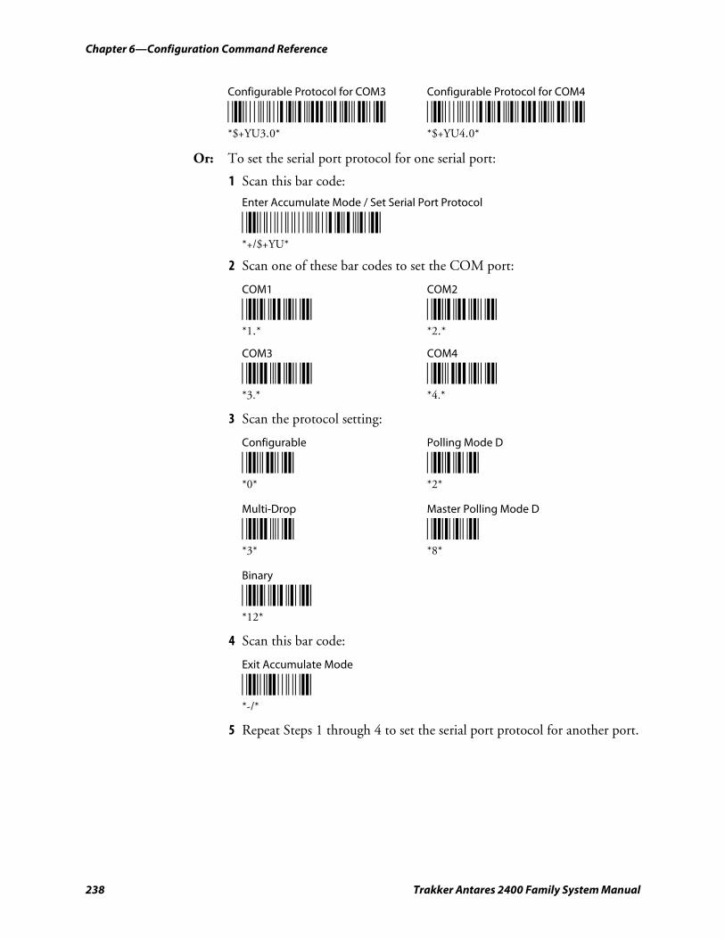
Chapter 6—Configuration Command Reference
238 Trakker Antares 2400 Family System Manual
Configurable Protocol for COM3 Configurable Protocol for COM4
*$+YU3.0* *$+YU4.0* *$+YU3.0* *$+YU4.0*
Or: To set the serial port protocol for one serial port:
1 Scan this bar code:
Enter Accumulate Mode / Set Serial Port Protocol
*+/$+YU* *+/$+YU*
2 Scan one of these bar codes to set the COM port:
COM1 COM2
*1.* *2.* *1.* *2.*
COM3 COM4
*3.* *4.* *3.* *4.*
3 Scan the protocol setting:
Configurable Polling Mode D
*0* *2* *0* *2*
Multi-Drop Master Polling Mode D
*3* *8* *3* *8*
Binary
*12* *12*
4 Scan this bar code:
Exit Accumulate Mode
*-/* *-/*
5 Repeat Steps 1 through 4 to set the serial port protocol for another port.
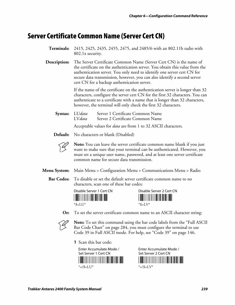
Chapter 6—Configuration Command Reference
Trakker Antares 2400 Family System Manual 239
Server Certificate Common Name (Server Cert CN)
Terminals: 2415, 2425, 2435, 2455, 2475, and 2485/6 with an 802.11b radio with 802.1x security.
Description: The Server Certificate Common Name (Server Cert CN) is the name of the certificate on the authentication server. You obtain this value from the authentication server. You only need to identify one server cert CN for secure data transmission, however, you can also identify a second server cert CN for a backup authentication server.
If the name of the certificate on the authentication server is longer than 32 characters, configure the server cert CN for the first 32 characters. You can authenticate to a certificate with a name that is longer than 32 characters, however, the terminal will only check the first 32 characters.
Syntax: LUdata Server 1 Certificate Common Name LVdata Server 2 Certificate Common Name
Acceptable values for data are from 1 to 32 ASCII characters.
Default: No characters or blank (Disabled)
Note: You can leave the server certificate common name blank if you just want to make sure that your terminal can be authenticated. However, you must set a unique user name, password, and at least one server certificate common name for secure data transmission.
Menu System: Main Menu > Configuration Menu > Communications Menu > Radio
Bar Codes: To disable or set the default server certificate common name to no characters, scan one of these bar codes:
Disable Server 1 Cert CN Disable Server 2 Cert CN
*$+LU* *$+LV* *$+LU* *$+LV*
Or: To set the server certificate common name to an ASCII character string:
Note: To set this command using the bar code labels from the “Full ASCII Bar Code Chart” on page 284, you must configure the terminal to use Code 39 in Full ASCII mode. For help, see “Code 39” on page 146.
1 Scan this bar code:
Enter Accumulate Mode / Enter Accumulate Mode / Set Server 1 Cert CN Set Server 2 Cert CN
*+/$+LU* *+/$+LV* *+/$+LU* *+/$+LV*
Chapter 6—Configuration Command Reference
240 Trakker Antares 2400 Family System Manual
2 Scan a value for data from the “Full ASCII Bar Code Chart” on page 284. The server certificate common name can be from 1 to 32 characters.
3 Scan this bar code:
Exit Accumulate Mode
*-/* *-/*
Start of Message (SOM)
Terminals: All Trakker Antares terminals.
Description: SOM is the first character in a message sent to or received from the host computer through one of the terminal’s serial ports. You can configure LRC for the Configurable communications protocol. For more information, see the networking chapter in your user’s manual.
You can set SOM to use characters from the extended ASCII character set using the TRAKKER Antares 2400 Menu System. This procedure is similar to the one for setting the preamble and postamble. For help, see “Entering ASCII Control Characters” in the configuration chapter in your user’s manual.
SOM cannot equal the same value that is set for EOM. You cannot set SOM to any of these values:
• AFF (ACK) • REQ (ENQ)
• DLE • SEL
• NEG (NAK) • XOFF
• Poll • XON
• RES (EOT)
Note: Before you can enable SOM, you must configure the EOM command.
Syntax: YYn.data
where n is:
1 COM1 serial port 2 COM2 serial port (246X and 248X terminals only) 3 COM3 serial port (242X terminals only) 4 COM4 serial port (242X, 2455, and 248X terminals only)
An acceptable value for data is any ASCII character.
Default: \x02 (hexadecimal value for STX)
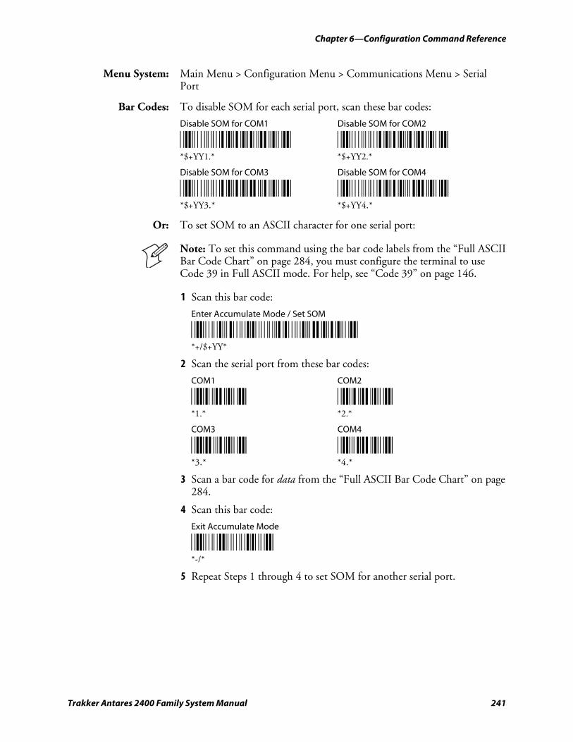
Chapter 6—Configuration Command Reference
Trakker Antares 2400 Family System Manual 241
Menu System: Main Menu > Configuration Menu > Communications Menu > Serial Port
Bar Codes: To disable SOM for each serial port, scan these bar codes:
Disable SOM for COM1 Disable SOM for COM2
*$+YY1.* *$+YY2.* *$+YY1.* *$+YY2.*
Disable SOM for COM3 Disable SOM for COM4
*$+YY3.* *$+YY4.* *$+YY3.* *$+YY4.*
Or: To set SOM to an ASCII character for one serial port:
Note: To set this command using the bar code labels from the “Full ASCII Bar Code Chart” on page 284, you must configure the terminal to use Code 39 in Full ASCII mode. For help, see “Code 39” on page 146.
1 Scan this bar code:
Enter Accumulate Mode / Set SOM
*/K/O/D/KYY* *+/$+YY*
2 Scan the serial port from these bar codes:
COM1 COM2
*1.* *2.* *1.* *2.*
COM3 COM4
*3.* *4.* *3.* *4.*
3 Scan a bar code for data from the “Full ASCII Bar Code Chart” on page 284.
4 Scan this bar code:
Exit Accumulate Mode
*/M/O* *-/*
5 Repeat Steps 1 through 4 to set SOM for another serial port.
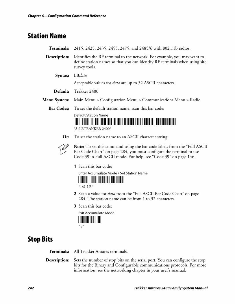
Chapter 6—Configuration Command Reference
242 Trakker Antares 2400 Family System Manual
Station Name
Terminals: 2415, 2425, 2435, 2455, 2475, and 2485/6 with 802.11b radios.
Description: Identifies the RF terminal to the network. For example, you may want to define station names so that you can identify RF terminals when using site survey tools.
Syntax: LBdata
Acceptable values for data are up to 32 ASCII characters.
Default: Trakker 2400
Menu System: Main Menu > Configuration Menu > Communications Menu > Radio
Bar Codes: To set the default station name, scan this bar code:
Default Station Name
*$+LBTRAKKER 2400* *$+LBTRAKKER 2400*
Or: To set the station name to an ASCII character string:
Note: To set this command using the bar code labels from the “Full ASCII Bar Code Chart” on page 284, you must configure the terminal to use Code 39 in Full ASCII mode. For help, see “Code 39” on page 146.
1 Scan this bar code:
Enter Accumulate Mode / Set Station Name
*+/$+LB* *+/$+LB*
2 Scan a value for data from the “Full ASCII Bar Code Chart” on page 284. The station name can be from 1 to 32 characters.
3 Scan this bar code:
Exit Accumulate Mode
*-/* *-/*
Stop Bits
Terminals: All Trakker Antares terminals.
Description: Sets the number of stop bits on the serial port. You can configure the stop bits for the Binary and Configurable communications protocols. For more information, see the networking chapter in your user’s manual.
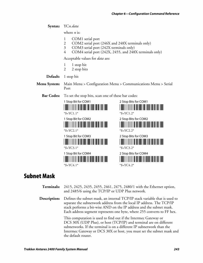
Chapter 6—Configuration Command Reference
Trakker Antares 2400 Family System Manual 243
Syntax: YCn.data
where n is:
1 COM1 serial port 2 COM2 serial port (246X and 248X terminals only) 3 COM3 serial port (242X terminals only) 4 COM4 serial port (242X, 2455, and 248X terminals only)
Acceptable values for data are:
1 1 stop bit 2 2 stop bits
Default: 1 stop bit
Menu System: Main Menu > Configuration Menu > Communications Menu > Serial Port
Bar Codes: To set the stop bits, scan one of these bar codes:
1 Stop Bit for COM1 2 Stop Bits for COM1
*$+YC1.1* *$+YC1.2* *$+YC1.1* *$+YC1.2*
1 Stop Bit for COM2 2 Stop Bits for COM2
*$+YC2.1* *$+YC2.2* *$+YC2.1* *$+YC2.2*
1 Stop Bit for COM3 2 Stop Bits for COM3
*$+YC3.1* *$+YC3.2* *$+YC3.1* *$+YC3.2*
1 Stop Bit for COM4 2 Stop Bits for COM4
*$+YC4.1* *$+YC4.2* *$+YC4.1* *$+YC4.2*
Subnet Mask
Terminals: 2415, 2425, 2435, 2455, 2461, 2475, 2480/1 with the Ethernet option, and 2485/6 using the TCP/IP or UDP Plus network.
Description: Defines the subnet mask, an internal TCP/IP stack variable that is used to separate the subnetwork address from the local IP address. The TCP/IP stack performs a bit-wise AND on the IP address and the subnet mask. Each address segment represents one byte, where 255 converts to FF hex.
This computation is used to find out if the Intermec Gateway or DCS 30X (UDP Plus), or host (TCP/IP) and terminal are on different subnetworks. If the terminal is on a different IP subnetwork than the Intermec Gateway or DCS 30X or host, you must set the subnet mask and the default router.
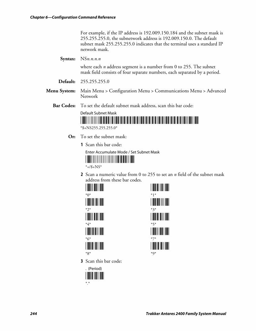
Chapter 6—Configuration Command Reference
244 Trakker Antares 2400 Family System Manual
For example, if the IP address is 192.009.150.184 and the subnet mask is 255.255.255.0, the subnetwork address is 192.009.150.0. The default subnet mask 255.255.255.0 indicates that the terminal uses a standard IP network mask.
Syntax: NSn.n.n.n
where each n address segment is a number from 0 to 255. The subnet mask field consists of four separate numbers, each separated by a period.
Default: 255.255.255.0
Menu System: Main Menu > Configuration Menu > Communications Menu > Advanced Network
Bar Codes: To set the default subnet mask address, scan this bar code:
Default Subnet Mask
*$+NS255.255.255.0* *$+NS255.255.255.0*
Or: To set the subnet mask:
1 Scan this bar code:
Enter Accumulate Mode / Set Subnet Mask
*+/$+NS* *+/$+NS*
2 Scan a numeric value from 0 to 255 to set an n field of the subnet mask address from these bar codes.
*0* *1* *0* *1*
*2* *3* *2* *3*
*4* *5* *4* *5*
*6* *7* *6* *7*
*8* *9* *8* *9*
3 Scan this bar code:
. (Period)
*.* *.*
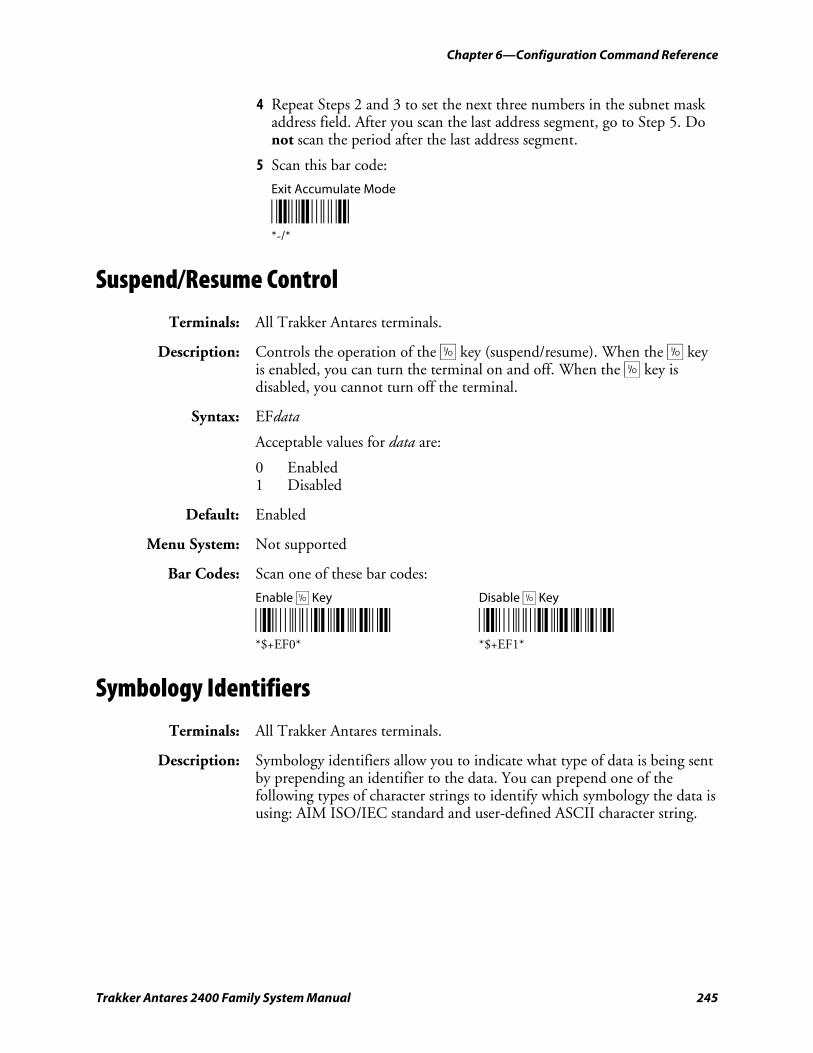
Chapter 6—Configuration Command Reference
Trakker Antares 2400 Family System Manual 245
4 Repeat Steps 2 and 3 to set the next three numbers in the subnet mask address field. After you scan the last address segment, go to Step 5. Do not scan the period after the last address segment.
5 Scan this bar code:
Exit Accumulate Mode
*-/* *-/*
Suspend/Resume Control
Terminals: All Trakker Antares terminals.
Description: Controls the operation of the œ key (suspend/resume). When the œ key is enabled, you can turn the terminal on and off. When the œ key is disabled, you cannot turn off the terminal.
Syntax: EFdata
Acceptable values for data are:
0 Enabled 1 Disabled
Default: Enabled
Menu System: Not supported
Bar Codes: Scan one of these bar codes:
Enable œ Key Disable œ Key
*$+EF0* *$+EF1* *$+EF0* *$+EF1*
Symbology Identifiers
Terminals: All Trakker Antares terminals.
Description: Symbology identifiers allow you to indicate what type of data is being sent by prepending an identifier to the data. You can prepend one of the following types of character strings to identify which symbology the data is using: AIM ISO/IEC standard and user-defined ASCII character string.
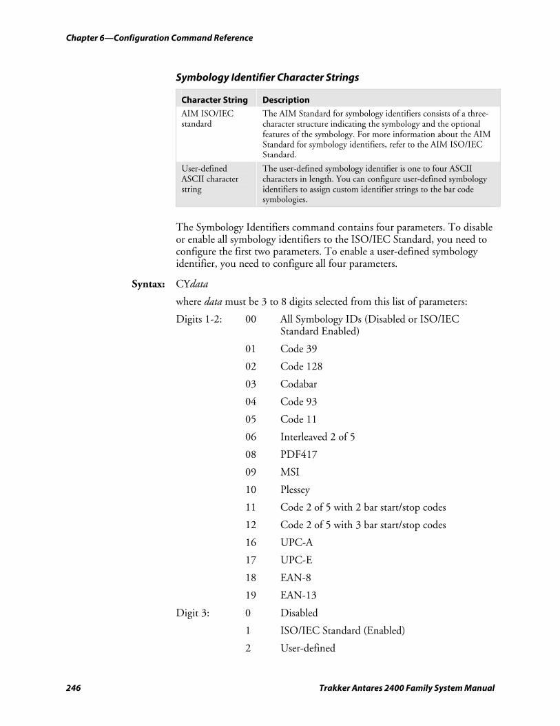
Chapter 6—Configuration Command Reference
246 Trakker Antares 2400 Family System Manual
Symbology Identifier Character Strings
Character String Description
AIM ISO/IEC standard
The AIM Standard for symbology identifiers consists of a three-character structure indicating the symbology and the optional features of the symbology. For more information about the AIM Standard for symbology identifiers, refer to the AIM ISO/IEC Standard.
User-defined ASCII character string
The user-defined symbology identifier is one to four ASCII characters in length. You can configure user-defined symbology identifiers to assign custom identifier strings to the bar code symbologies.
The Symbology Identifiers command contains four parameters. To disable or enable all symbology identifiers to the ISO/IEC Standard, you need to configure the first two parameters. To enable a user-defined symbology identifier, you need to configure all four parameters.
Syntax: CYdata
where data must be 3 to 8 digits selected from this list of parameters:
Digits 1-2: 00 All Symbology IDs (Disabled or ISO/IEC Standard Enabled)
01 Code 39
02 Code 128
03 Codabar
04 Code 93
05 Code 11
06 Interleaved 2 of 5
08 PDF417
09 MSI
10 Plessey
11 Code 2 of 5 with 2 bar start/stop codes
12 Code 2 of 5 with 3 bar start/stop codes
16 UPC-A
17 UPC-E
18 EAN-8
19 EAN-13
Digit 3: 0 Disabled
1 ISO/IEC Standard (Enabled)
2 User-defined
Chapter 6—Configuration Command Reference
Trakker Antares 2400 Family System Manual 247
Digit 4: 1 User-defined character string length of 1
2 User-defined character string length of 2
3 User-defined character string length of 3
4 User-defined character string length of 4
Digits 5-8: xxxx ASCII string of 1 to 4 characters in length indicating the user-defined value.
Note: The PDF417 symbology identifier is not available on terminals that are not configured to scan PDF417 bar code labels. You also may be able to define symbology identifiers for bar code symbologies that the terminal is not configured to support.
Default: 000 (all symbology identifiers disabled)
Note: To set this command using the bar code labels from the “Full ASCII Bar Code Chart” on page 284, you must configure the terminal to use Code 39 in Full ASCII mode. For help, see “Code 39” on page 146.
Menu System: To configure symbology identifiers using the Menu System:
1 From the Main Menu, choose Configuration Menu > Symbology IDs Menu.
2 Set all symbology identifiers to the ISO/IEC Standard.
a Select All Symbology IDs.
b Set the command to ISO/IEC Std. (Enabled).
3 Select a symbology identifier, or select all symbology identifiers with the All Symbology IDs option.
4 Set the symbology identifier to Disabled, ISO/IEC Standard (Enabled), or User-Defined. If you select User-Defined, continue with Step 5. Otherwise continue with Step 7.
If you selected the All Symbology IDs option in Step 3, you can only select Disabled or ISO/IEC Standard (Enabled). You must individually select a symbology to set a user-defined symbology identifier.
5 Set a user-defined character string length from 1 to 4.
6 Select a value for the user-defined symbology ID from the “Full ASCII Bar Code Chart” on page 284. The user-defined symbology ID should be 1 to 4 characters in length depending on the character string length value that you set in Step 5.
7 Repeat Steps 3 to 6 to configure another symbology identifier.
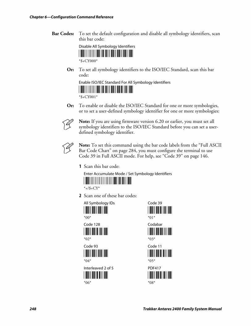
Chapter 6—Configuration Command Reference
248 Trakker Antares 2400 Family System Manual
Bar Codes: To set the default configuration and disable all symbology identifiers, scan this bar code:
Disable All Symbology Identifiers
*$+CY000* *$+CY000*
Or: To set all symbology identifiers to the ISO/IEC Standard, scan this bar code:
Enable ISO/IEC Standard For All Symbology Identifiers
*$+CY001* *$+CY001*
Or: To enable or disable the ISO/IEC Standard for one or more symbologies, or to set a user-defined symbology identifier for one or more symbologies:
Note: If you are using firmware version 6.20 or earlier, you must set all symbology identifiers to the ISO/IEC Standard before you can set a user-defined symbology identifier.
Note: To set this command using the bar code labels from the “Full ASCII Bar Code Chart” on page 284, you must configure the terminal to use Code 39 in Full ASCII mode. For help, see “Code 39” on page 146.
1 Scan this bar code:
Enter Accumulate Mode / Set Symbology Identifiers
*+/$+CY* *+/$+CY*
2 Scan one of these bar codes:
All Symbology IDs Code 39
*00* *01* *00* *01*
Code 128 Codabar
*02* *03* *02* *03*
Code 93 Code 11
*04* *05* *04* *05*
Interleaved 2 of 5 PDF417
*06* *08* *06* *08*
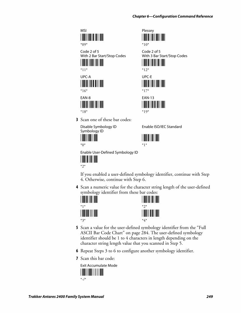
Chapter 6—Configuration Command Reference
Trakker Antares 2400 Family System Manual 249
MSI Plessey
*09* *10* *09* *10*
Code 2 of 5 Code 2 of 5 With 2 Bar Start/Stop Codes With 3 Bar Start/Stop Codes
*11* *12* *11* *12*
UPC-A UPC-E
*16* *17* *16* *17*
EAN-8 EAN-13
*18* *19* *18* *19*
3 Scan one of these bar codes:
Disable Symbology ID Enable ISO/IEC Standard Symbology ID
*0* *1* *0* *1*
Enable User-Defined Symbology ID
*2* *2*
If you enabled a user-defined symbology identifier, continue with Step 4. Otherwise, continue with Step 6.
4 Scan a numeric value for the character string length of the user-defined symbology identifier from these bar codes:
*1* *2* *1* *2*
*3* *4* *3* *4*
5 Scan a value for the user-defined symbology identifier from the “Full ASCII Bar Code Chart” on page 284. The user-defined symbology identifier should be 1 to 4 characters in length depending on the character string length value that you scanned in Step 5.
6 Repeat Steps 3 to 6 to configure another symbology identifier.
7 Scan this bar code:
Exit Accumulate Mode
*-/* *-/*
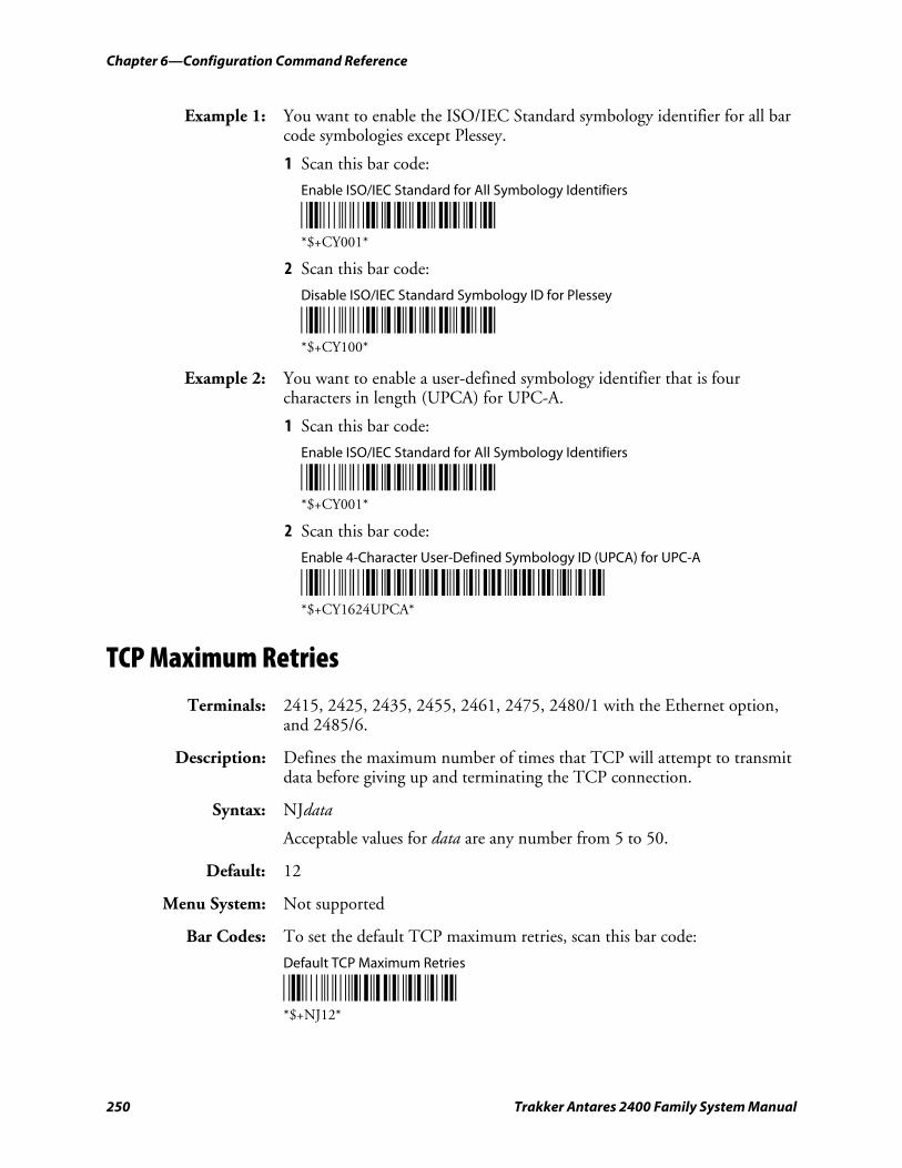
Chapter 6—Configuration Command Reference
250 Trakker Antares 2400 Family System Manual
Example 1: You want to enable the ISO/IEC Standard symbology identifier for all bar code symbologies except Plessey.
1 Scan this bar code:
Enable ISO/IEC Standard for All Symbology Identifiers
*$+CY001* *$+CY001*
2 Scan this bar code:
Disable ISO/IEC Standard Symbology ID for Plessey
*$+CY100* *$+CY100*
Example 2: You want to enable a user-defined symbology identifier that is four characters in length (UPCA) for UPC-A.
1 Scan this bar code:
Enable ISO/IEC Standard for All Symbology Identifiers
*$+CY001* *$+CY001*
2 Scan this bar code:
Enable 4-Character User-Defined Symbology ID (UPCA) for UPC-A
*$+CY1624UPCA* *$+CY1624UPCA*
TCP Maximum Retries
Terminals: 2415, 2425, 2435, 2455, 2461, 2475, 2480/1 with the Ethernet option, and 2485/6.
Description: Defines the maximum number of times that TCP will attempt to transmit data before giving up and terminating the TCP connection.
Syntax: NJdata
Acceptable values for data are any number from 5 to 50.
Default: 12
Menu System: Not supported
Bar Codes: To set the default TCP maximum retries, scan this bar code:
Default TCP Maximum Retries
*$+NJ12* *$+NJ12*
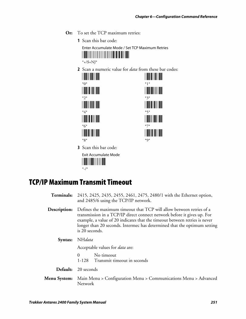
Chapter 6—Configuration Command Reference
Trakker Antares 2400 Family System Manual 251
Or: To set the TCP maximum retries:
1 Scan this bar code:
Enter Accumulate Mode / Set TCP Maximum Retries
*+/$+NJ* *+/$+NJ*
2 Scan a numeric value for data from these bar codes:
*0* *1* *0* *1*
*2* *3* *2* *3*
*4* *5* *4* *5*
*6* *7* *6* *7*
*8* *9* *8* *9*
3 Scan this bar code:
Exit Accumulate Mode
*-/* *-/*
TCP/IP Maximum Transmit Timeout
Terminals: 2415, 2425, 2435, 2455, 2461, 2475, 2480/1 with the Ethernet option, and 2485/6 using the TCP/IP network.
Description: Defines the maximum timeout that TCP will allow between retries of a transmission in a TCP/IP direct connect network before it gives up. For example, a value of 20 indicates that the timeout between retries is never longer than 20 seconds. Intermec has determined that the optimum setting is 20 seconds.
Syntax: NHdata
Acceptable values for data are:
0 No timeout 1-128 Transmit timeout in seconds
Default: 20 seconds
Menu System: Main Menu > Configuration Menu > Communications Menu > Advanced Network
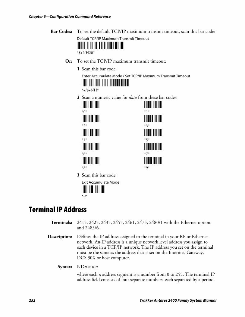
Chapter 6—Configuration Command Reference
252 Trakker Antares 2400 Family System Manual
Bar Codes: To set the default TCP/IP maximum transmit timeout, scan this bar code:
Default TCP/IP Maximum Transmit Timeout
*$+NH20* *$+NH20*
Or: To set the TCP/IP maximum transmit timeout:
1 Scan this bar code:
Enter Accumulate Mode / Set TCP/IP Maximum Transmit Timeout
*+/$+NH* *+/$+NH*
2 Scan a numeric value for data from these bar codes:
*0* *1* *0* *1*
*2* *3* *2* *3*
*4* *5* *4* *5*
*6* *7* *6* *7*
*8* *9* *8* *9*
3 Scan this bar code:
Exit Accumulate Mode
*-/* *-/*
Terminal IP Address
Terminals: 2415, 2425, 2435, 2455, 2461, 2475, 2480/1 with the Ethernet option, and 2485/6.
Description: Defines the IP address assigned to the terminal in your RF or Ethernet network. An IP address is a unique network level address you assign to each device in a TCP/IP network. The IP address you set on the terminal must be the same as the address that is set on the Intermec Gateway, DCS 30X or host computer.
Syntax: NDn.n.n.n
where each n address segment is a number from 0 to 255. The terminal IP address field consists of four separate numbers, each separated by a period.
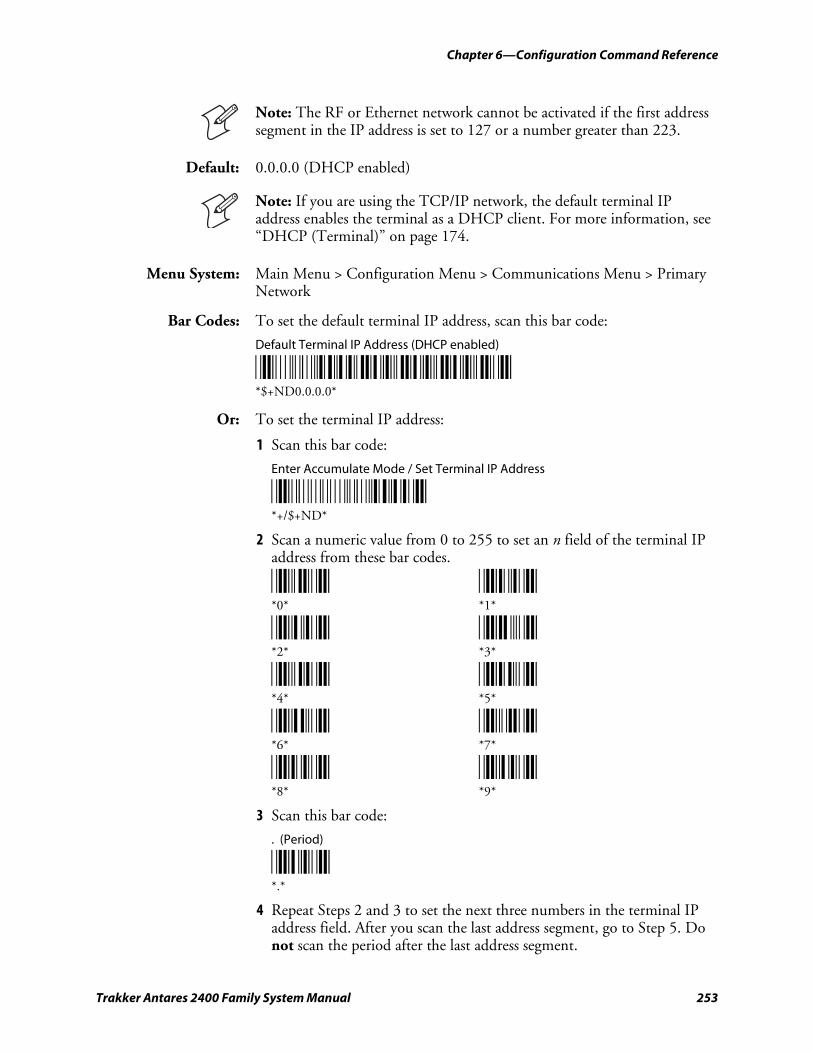
Chapter 6—Configuration Command Reference
Trakker Antares 2400 Family System Manual 253
Note: The RF or Ethernet network cannot be activated if the first address segment in the IP address is set to 127 or a number greater than 223.
Default: 0.0.0.0 (DHCP enabled)
Note: If you are using the TCP/IP network, the default terminal IP address enables the terminal as a DHCP client. For more information, see “DHCP (Terminal)” on page 174.
Menu System: Main Menu > Configuration Menu > Communications Menu > Primary Network
Bar Codes: To set the default terminal IP address, scan this bar code:
Default Terminal IP Address (DHCP enabled)
*$+ND0.0.0.0* *$+ND0.0.0.0*
Or: To set the terminal IP address:
1 Scan this bar code:
Enter Accumulate Mode / Set Terminal IP Address
*+/$+ND* *+/$+ND*
2 Scan a numeric value from 0 to 255 to set an n field of the terminal IP address from these bar codes.
*0* *1* *0* *1*
*2* *3* *2* *3*
*4* *5* *4* *5*
*6* *7* *6* *7*
*8* *9* *8* *9*
3 Scan this bar code:
. (Period)
*.* *.*
4 Repeat Steps 2 and 3 to set the next three numbers in the terminal IP address field. After you scan the last address segment, go to Step 5. Do not scan the period after the last address segment.
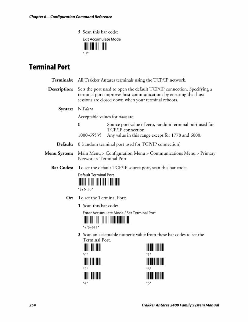
Chapter 6—Configuration Command Reference
254 Trakker Antares 2400 Family System Manual
5 Scan this bar code:
Exit Accumulate Mode
*-/* *-/*
Terminal Port
Terminals: All Trakker Antares terminals using the TCP/IP network.
Description: Sets the port used to open the default TCP/IP connection. Specifying a terminal port improves host communications by ensuring that host sessions are closed down when your terminal reboots.
Syntax: NTdata
Acceptable values for data are:
0 Source port value of zero, random terminal port used for TCP/IP connection 1000-65535 Any value in this range except for 1778 and 6000.
Default: 0 (random terminal port used for TCP/IP connection)
Menu System: Main Menu > Configuration Menu > Communications Menu > Primary Network > Terminal Port
Bar Codes: To set the default TCP/IP source port, scan this bar code:
Default Terminal Port
*$+NT0* *$+NT0*
Or: To set the Terminal Port:
1 Scan this bar code:
Enter Accumulate Mode / Set Terminal Port
*+/$+NT* *+/$+NT*
2 Scan an acceptable numeric value from these bar codes to set the Terminal Port.
*0* *1* *0* *1*
*2* *3* *2* *3*
*4* *5* *4* *5*
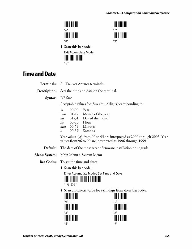
Chapter 6—Configuration Command Reference
Trakker Antares 2400 Family System Manual 255
*6* *7* *6* *7*
*8* *9* *8* *9*
3 Scan this bar code:
Exit Accumulate Mode
*-/* *-/*
Time and Date
Terminals: All Trakker Antares terminals.
Description: Sets the time and date on the terminal.
Syntax: DBdata
Acceptable values for data are 12 digits corresponding to:
yy 00-99 Year mm 01-12 Month of the year dd 01-31 Day of the month hh 00-23 Hour mm 00-59 Minutes ss 00-59 Seconds
Year values (yy) from 00 to 95 are interpreted as 2000 through 2095. Year values from 96 to 99 are interpreted as 1996 through 1999.
Default: The date of the most recent firmware installation or upgrade.
Menu System: Main Menu > System Menu
Bar Codes: To set the time and date:
1 Scan this bar code:
Enter Accumulate Mode / Set Time and Date
*+/$+DB* *+/$+DB*
2 Scan a numeric value for each digit from these bar codes:
*0* *1* *0* *1*
*2* *3* *2* *3*
*4* *5* *4* *5*
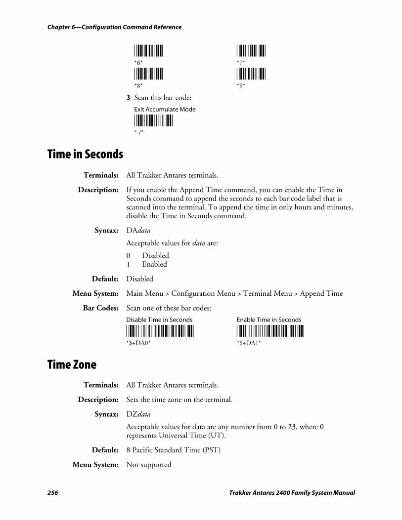
Chapter 6—Configuration Command Reference
256 Trakker Antares 2400 Family System Manual
*6* *7* *6* *7*
*8* *9* *8* *9*
3 Scan this bar code:
Exit Accumulate Mode
*-/* *-/*
Time in Seconds
Terminals: All Trakker Antares terminals.
Description: If you enable the Append Time command, you can enable the Time in Seconds command to append the seconds to each bar code label that is scanned into the terminal. To append the time in only hours and minutes, disable the Time in Seconds command.
Syntax: DAdata
Acceptable values for data are:
0 Disabled 1 Enabled
Default: Disabled
Menu System: Main Menu > Configuration Menu > Terminal Menu > Append Time
Bar Codes: Scan one of these bar codes:
Disable Time in Seconds Enable Time in Seconds
*$+DA0* *$+DA1* *$+DA0* *$+DA1*
Time Zone Terminals: All Trakker Antares terminals.
Description: Sets the time zone on the terminal.
Syntax: DZdata
Acceptable values for data are any number from 0 to 23, where 0 represents Universal Time (UT).
Default: 8 Pacific Standard Time (PST)
Menu System: Not supported
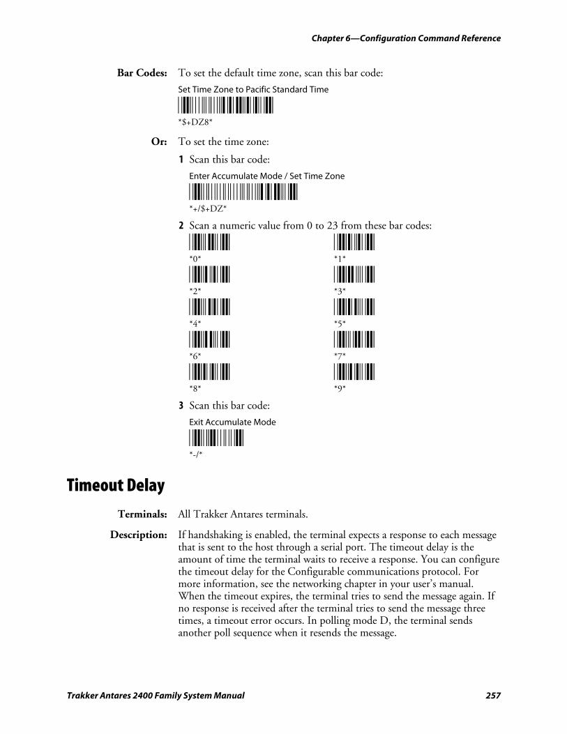
Chapter 6—Configuration Command Reference
Trakker Antares 2400 Family System Manual 257
Bar Codes: To set the default time zone, scan this bar code:
Set Time Zone to Pacific Standard Time
*$+DZ8* *$+DZ8*
Or: To set the time zone:
1 Scan this bar code:
Enter Accumulate Mode / Set Time Zone
*+/$+DZ* *+/$+DZ*
2 Scan a numeric value from 0 to 23 from these bar codes:
*0* *1* *0* *1*
*2* *3* *2* *3*
*4* *5* *4* *5*
*6* *7* *6* *7*
*8* *9* *8* *9*
3 Scan this bar code:
Exit Accumulate Mode
*-/* *-/*
Timeout Delay
Terminals: All Trakker Antares terminals.
Description: If handshaking is enabled, the terminal expects a response to each message that is sent to the host through a serial port. The timeout delay is the amount of time the terminal waits to receive a response. You can configure the timeout delay for the Configurable communications protocol. For more information, see the networking chapter in your user’s manual. When the timeout expires, the terminal tries to send the message again. If no response is received after the terminal tries to send the message three times, a timeout error occurs. In polling mode D, the terminal sends another poll sequence when it resends the message.
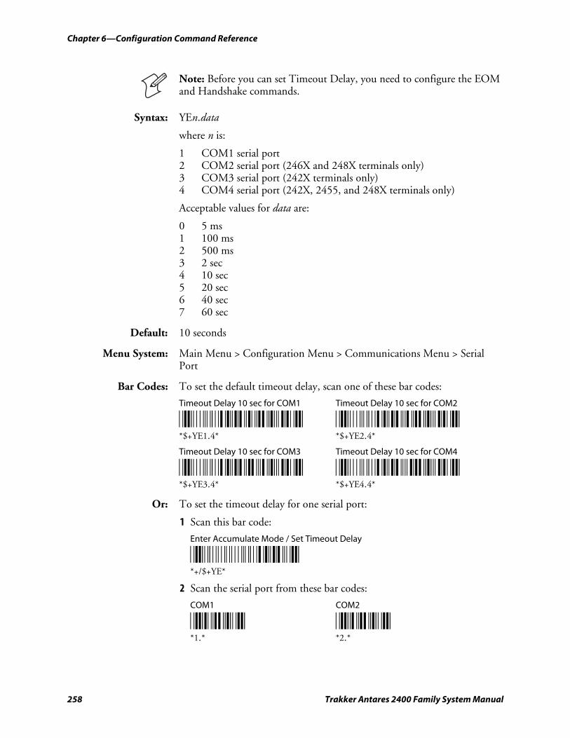
Chapter 6—Configuration Command Reference
258 Trakker Antares 2400 Family System Manual
Note: Before you can set Timeout Delay, you need to configure the EOM and Handshake commands.
Syntax: YEn.data
where n is:
1 COM1 serial port 2 COM2 serial port (246X and 248X terminals only) 3 COM3 serial port (242X terminals only) 4 COM4 serial port (242X, 2455, and 248X terminals only)
Acceptable values for data are:
0 5 ms 1 100 ms 2 500 ms 3 2 sec 4 10 sec 5 20 sec 6 40 sec 7 60 sec
Default: 10 seconds
Menu System: Main Menu > Configuration Menu > Communications Menu > Serial Port
Bar Codes: To set the default timeout delay, scan one of these bar codes:
Timeout Delay 10 sec for COM1 Timeout Delay 10 sec for COM2
*$+YE1.4* *$+YE2.4* *$+YE1.4* *$+YE2.4*
Timeout Delay 10 sec for COM3 Timeout Delay 10 sec for COM4
*$+YE3.4* *$+YE4.4* *$+YE3.4* *$+YE4.4*
Or: To set the timeout delay for one serial port:
1 Scan this bar code:
Enter Accumulate Mode / Set Timeout Delay
*+/$+YE* *+/$+YE*
2 Scan the serial port from these bar codes:
COM1 COM2
*1.* *2.* *1.* *2.*
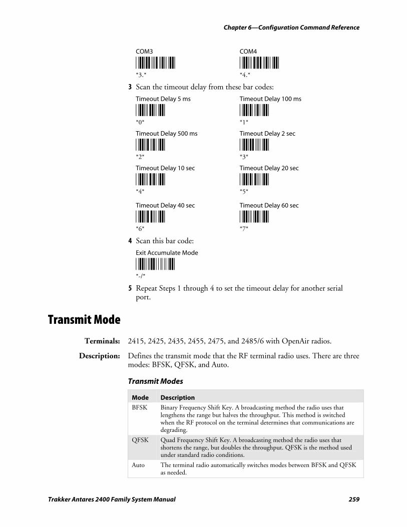
Chapter 6—Configuration Command Reference
Trakker Antares 2400 Family System Manual 259
COM3 COM4
*3.* *4.* *3.* *4.*
3 Scan the timeout delay from these bar codes:
Timeout Delay 5 ms Timeout Delay 100 ms
*0* *1* *0* *1*
Timeout Delay 500 ms Timeout Delay 2 sec
*2* *3* *2* *3*
Timeout Delay 10 sec Timeout Delay 20 sec
*4* *5* *4* *5*
Timeout Delay 40 sec Timeout Delay 60 sec
*6* *7* *6* *7*
4 Scan this bar code:
Exit Accumulate Mode
*-/* *-/*
5 Repeat Steps 1 through 4 to set the timeout delay for another serial port.
Transmit Mode
Terminals: 2415, 2425, 2435, 2455, 2475, and 2485/6 with OpenAir radios.
Description: Defines the transmit mode that the RF terminal radio uses. There are three modes: BFSK, QFSK, and Auto.
Transmit Modes
Mode Description
BFSK Binary Frequency Shift Key. A broadcasting method the radio uses that lengthens the range but halves the throughput. This method is switched when the RF protocol on the terminal determines that communications are degrading.
QFSK Quad Frequency Shift Key. A broadcasting method the radio uses that shortens the range, but doubles the throughput. QFSK is the method used under standard radio conditions.
Auto The terminal radio automatically switches modes between BFSK and QFSK as needed.
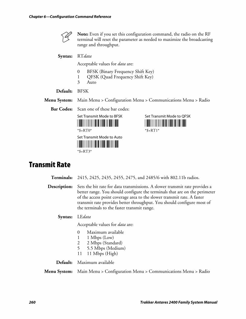
Chapter 6—Configuration Command Reference
260 Trakker Antares 2400 Family System Manual
Note: Even if you set this configuration command, the radio on the RF terminal will reset the parameter as needed to maximize the broadcasting range and throughput.
Syntax: RTdata
Acceptable values for data are:
0 BFSK (Binary Frequency Shift Key) 1 QFSK (Quad Frequency Shift Key) 3 Auto
Default: BFSK
Menu System: Main Menu > Configuration Menu > Communications Menu > Radio
Bar Codes: Scan one of these bar codes:
Set Transmit Mode to BFSK Set Transmit Mode to QFSK
*$+RT0* *$+RT1* *$+RT0* *$+RT1*
Set Transmit Mode to Auto
*$+RT3* *$+RT3*
Transmit Rate
Terminals: 2415, 2425, 2435, 2455, 2475, and 2485/6 with 802.11b radios.
Description: Sets the bit rate for data transmissions. A slower transmit rate provides a better range. You should configure the terminals that are on the perimeter of the access point coverage area to the slower transmit rate. A faster transmit rate provides better throughput. You should configure most of the terminals to the faster transmit range.
Syntax: LEdata
Acceptable values for data are:
0 Maximum available 1 1 Mbps (Low) 2 2 Mbps (Standard) 5 5.5 Mbps (Medium) 11 11 Mbps (High)
Default: Maximum available
Menu System: Main Menu > Configuration Menu > Communications Menu > Radio
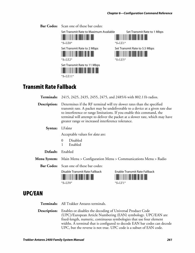
Chapter 6—Configuration Command Reference
Trakker Antares 2400 Family System Manual 261
Bar Codes: Scan one of these bar codes:
Set Transmit Rate to Maximum Available Set Transmit Rate to 1 Mbps
*$+LE0* *$+LE1* *$+LE0* *$+LE1*
Set Transmit Rate to 2 Mbps Set Transmit Rate to 5.5 Mbps
*$+LE2* *$+LE5* *$+LE2* *$+LE5*
Set Transmit Rate to 11 Mbps
*$+LE11* *$+LE11*
Transmit Rate Fallback
Terminals: 2415, 2425, 2435, 2455, 2475, and 2485/6 with 802.11b radios.
Description: Determines if the RF terminal will try slower rates than the specified transmit rate. A packet may be undeliverable to a device at a given rate due to interference or range limitations. If you enable this command, the terminal will attempt to deliver the packet at a slower rate, which may have greater range or increased interference tolerance.
Syntax: LFdata
Acceptable values for data are:
0 Disabled 1 Enabled
Default: Enabled
Menu System: Main Menu > Configuration Menu > Communications Menu > Radio
Bar Codes: Scan one of these bar codes:
Disable Transmit Rate Fallback Enable Transmit Rate Fallback
*$+LF0* *$+LF1* *$+LF0* *$+LF1*
UPC/EAN
Terminals: All Trakker Antares terminals.
Description: Enables or disables the decoding of Universal Product Code (UPC)/European Article Numbering (EAN) symbology. UPC/EAN are fixed-length, numeric, continuous symbologies that use four element widths. A terminal that is configured to decode EAN bar codes can decode UPC, but the reverse is not true. UPC code is a subset of EAN code.
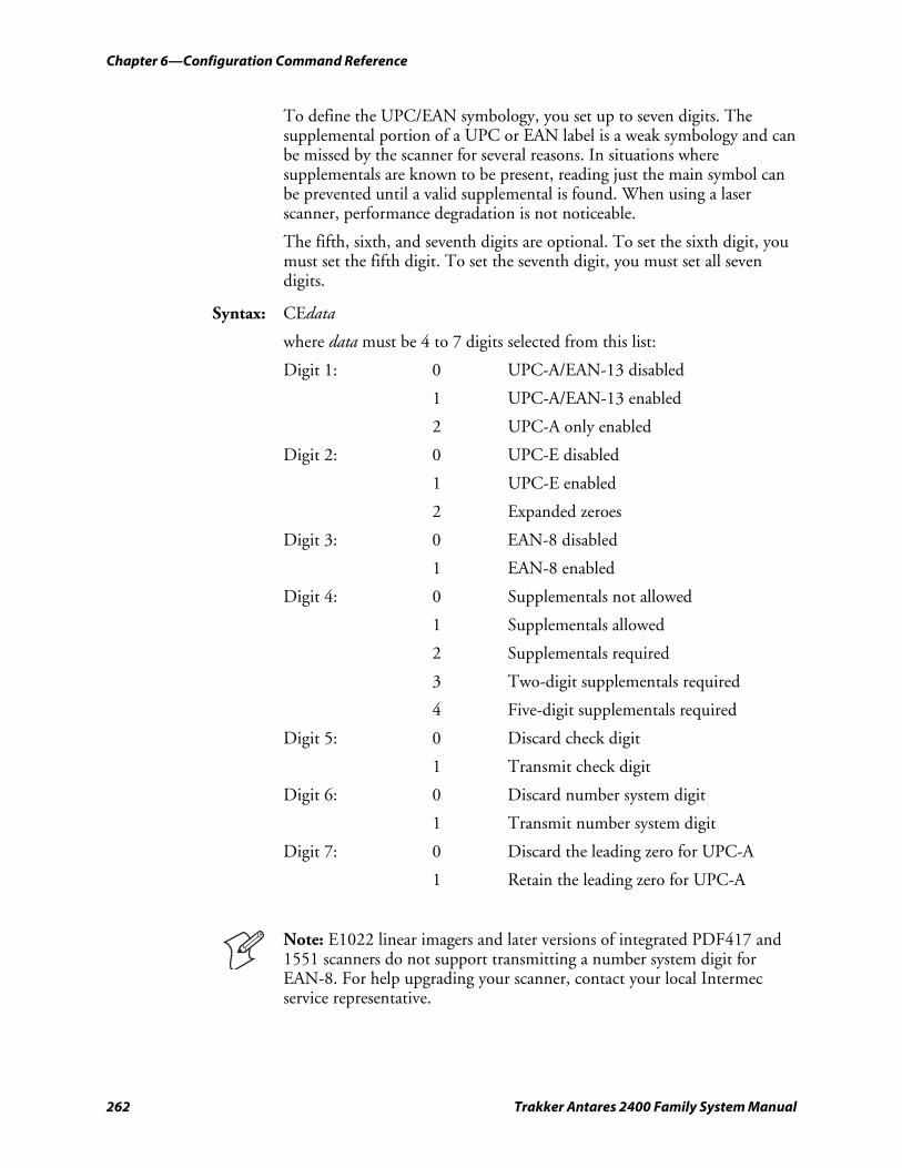
Chapter 6—Configuration Command Reference
262 Trakker Antares 2400 Family System Manual
To define the UPC/EAN symbology, you set up to seven digits. The supplemental portion of a UPC or EAN label is a weak symbology and can be missed by the scanner for several reasons. In situations where supplementals are known to be present, reading just the main symbol can be prevented until a valid supplemental is found. When using a laser scanner, performance degradation is not noticeable.
The fifth, sixth, and seventh digits are optional. To set the sixth digit, you must set the fifth digit. To set the seventh digit, you must set all seven digits.
Syntax: CEdata
where data must be 4 to 7 digits selected from this list:
Digit 1: 0 UPC-A/EAN-13 disabled
1 UPC-A/EAN-13 enabled
2 UPC-A only enabled
Digit 2: 0 UPC-E disabled
1 UPC-E enabled
2 Expanded zeroes
Digit 3: 0 EAN-8 disabled
1 EAN-8 enabled
Digit 4: 0 Supplementals not allowed
1 Supplementals allowed
2 Supplementals required
3 Two-digit supplementals required
4 Five-digit supplementals required
Digit 5: 0 Discard check digit
1 Transmit check digit
Digit 6: 0 Discard number system digit
1 Transmit number system digit
Digit 7: 0 Discard the leading zero for UPC-A
1 Retain the leading zero for UPC-A
Note: E1022 linear imagers and later versions of integrated PDF417 and 1551 scanners do not support transmitting a number system digit for EAN-8. For help upgrading your scanner, contact your local Intermec service representative.
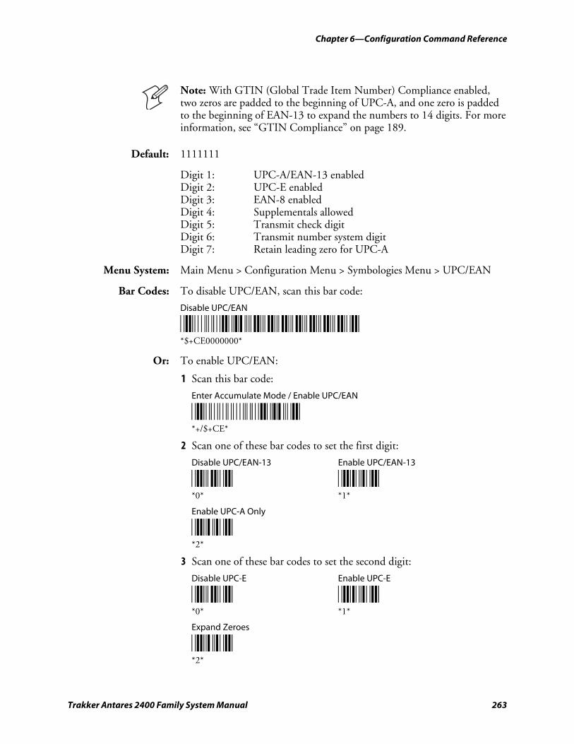
Chapter 6—Configuration Command Reference
Trakker Antares 2400 Family System Manual 263
Note: With GTIN (Global Trade Item Number) Compliance enabled, two zeros are padded to the beginning of UPC-A, and one zero is padded to the beginning of EAN-13 to expand the numbers to 14 digits. For more information, see “GTIN Compliance” on page 189.
Default: 1111111
Digit 1: UPC-A/EAN-13 enabled Digit 2: UPC-E enabled Digit 3: EAN-8 enabled Digit 4: Supplementals allowed Digit 5: Transmit check digit Digit 6: Transmit number system digit Digit 7: Retain leading zero for UPC-A
Menu System: Main Menu > Configuration Menu > Symbologies Menu > UPC/EAN
Bar Codes: To disable UPC/EAN, scan this bar code:
Disable UPC/EAN
*$+CE0000000* *$+CE0000000*
Or: To enable UPC/EAN:
1 Scan this bar code:
Enter Accumulate Mode / Enable UPC/EAN
*+/$+CE* *+/$+CE*
2 Scan one of these bar codes to set the first digit:
Disable UPC/EAN-13 Enable UPC/EAN-13
*0* *1* *0* *1*
Enable UPC-A Only
*2* *2*
3 Scan one of these bar codes to set the second digit:
Disable UPC-E Enable UPC-E
*0* *1* *0* *1*
Expand Zeroes
*2* *2*
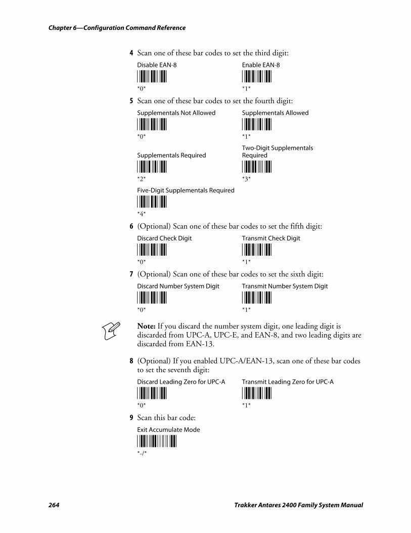
Chapter 6—Configuration Command Reference
264 Trakker Antares 2400 Family System Manual
4 Scan one of these bar codes to set the third digit:
Disable EAN-8 Enable EAN-8
*0* *1* *0* *1*
5 Scan one of these bar codes to set the fourth digit:
Supplementals Not Allowed Supplementals Allowed
*0* *1* *0* *1*
Two-Digit Supplementals Supplementals Required Required
*2* *3* *2* *3*
Five-Digit Supplementals Required
*4* *4*
6 (Optional) Scan one of these bar codes to set the fifth digit:
Discard Check Digit Transmit Check Digit
*0* *1* *0* *1*
7 (Optional) Scan one of these bar codes to set the sixth digit:
Discard Number System Digit Transmit Number System Digit
*0* *1* *0* *1*
Note: If you discard the number system digit, one leading digit is discarded from UPC-A, UPC-E, and EAN-8, and two leading digits are discarded from EAN-13.
8 (Optional) If you enabled UPC-A/EAN-13, scan one of these bar codes to set the seventh digit:
Discard Leading Zero for UPC-A Transmit Leading Zero for UPC-A
*0* *1* *0* *1*
9 Scan this bar code:
Exit Accumulate Mode
*-/* *-/*
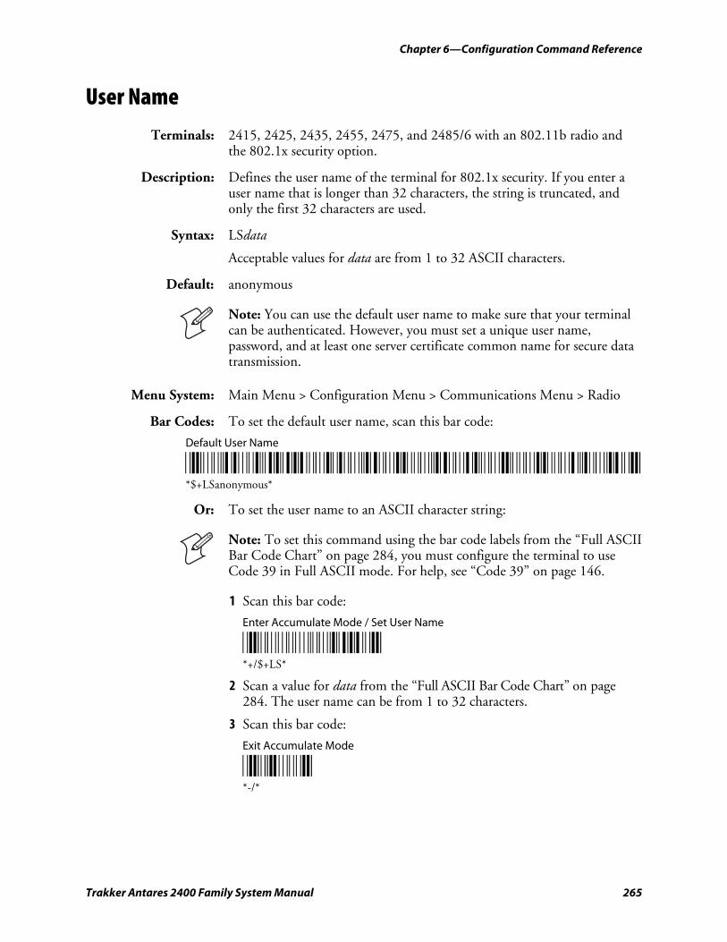
Chapter 6—Configuration Command Reference
Trakker Antares 2400 Family System Manual 265
User Name
Terminals: 2415, 2425, 2435, 2455, 2475, and 2485/6 with an 802.11b radio and the 802.1x security option.
Description: Defines the user name of the terminal for 802.1x security. If you enter a user name that is longer than 32 characters, the string is truncated, and only the first 32 characters are used.
Syntax: LSdata
Acceptable values for data are from 1 to 32 ASCII characters.
Default: anonymous
Note: You can use the default user name to make sure that your terminal can be authenticated. However, you must set a unique user name, password, and at least one server certificate common name for secure data transmission.
Menu System: Main Menu > Configuration Menu > Communications Menu > Radio
Bar Codes: To set the default user name, scan this bar code:
Default User Name
*/D/KLS+A+N+O+N+Y+M+O+U+S* *$+LSanonymous*
Or: To set the user name to an ASCII character string:
Note: To set this command using the bar code labels from the “Full ASCII Bar Code Chart” on page 284, you must configure the terminal to use Code 39 in Full ASCII mode. For help, see “Code 39” on page 146.
1 Scan this bar code:
Enter Accumulate Mode / Set User Name
*+/$+LS* *+/$+LS*
2 Scan a value for data from the “Full ASCII Bar Code Chart” on page 284. The user name can be from 1 to 32 characters.
3 Scan this bar code:
Exit Accumulate Mode
*-/* *-/*
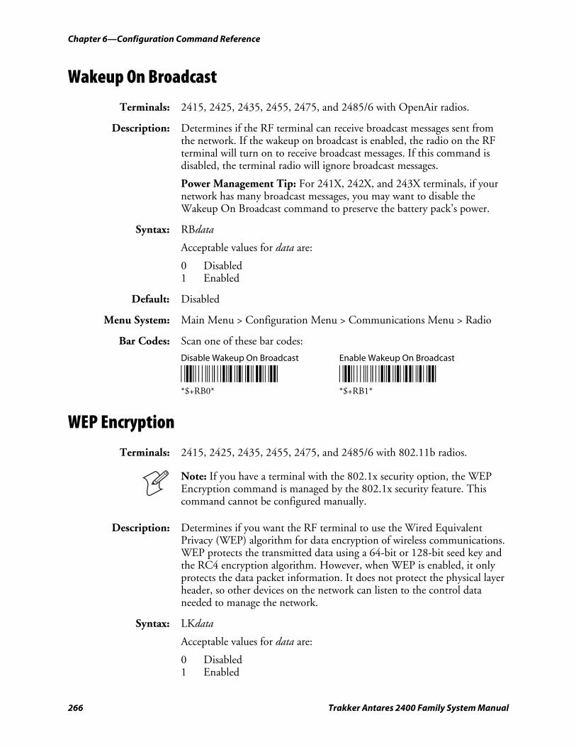
Chapter 6—Configuration Command Reference
266 Trakker Antares 2400 Family System Manual
Wakeup On Broadcast
Terminals: 2415, 2425, 2435, 2455, 2475, and 2485/6 with OpenAir radios.
Description: Determines if the RF terminal can receive broadcast messages sent from the network. If the wakeup on broadcast is enabled, the radio on the RF terminal will turn on to receive broadcast messages. If this command is disabled, the terminal radio will ignore broadcast messages.
Power Management Tip: For 241X, 242X, and 243X terminals, if your network has many broadcast messages, you may want to disable the Wakeup On Broadcast command to preserve the battery pack’s power.
Syntax: RBdata
Acceptable values for data are:
0 Disabled 1 Enabled
Default: Disabled
Menu System: Main Menu > Configuration Menu > Communications Menu > Radio
Bar Codes: Scan one of these bar codes:
Disable Wakeup On Broadcast Enable Wakeup On Broadcast
*$+RB0* *$+RB1* *$+RB0* *$+RB1*
WEP Encryption
Terminals: 2415, 2425, 2435, 2455, 2475, and 2485/6 with 802.11b radios.
Note: If you have a terminal with the 802.1x security option, the WEP Encryption command is managed by the 802.1x security feature. This command cannot be configured manually.
Description: Determines if you want the RF terminal to use the Wired Equivalent Privacy (WEP) algorithm for data encryption of wireless communications. WEP protects the transmitted data using a 64-bit or 128-bit seed key and the RC4 encryption algorithm. However, when WEP is enabled, it only protects the data packet information. It does not protect the physical layer header, so other devices on the network can listen to the control data needed to manage the network.
Syntax: LKdata
Acceptable values for data are:
0 Disabled 1 Enabled
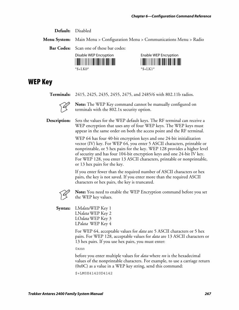
Chapter 6—Configuration Command Reference
Trakker Antares 2400 Family System Manual 267
Default: Disabled
Menu System: Main Menu > Configuration Menu > Communications Menu > Radio
Bar Codes: Scan one of these bar codes:
Disable WEP Encryption Enable WEP Encryption
*$+LK0* *$+LK1* *$+LK0* *$+LK1*
WEP Key
Terminals: 2415, 2425, 2435, 2455, 2475, and 2485/6 with 802.11b radios.
Note: The WEP Key command cannot be manually configured on terminals with the 802.1x security option.
Description: Sets the values for the WEP default keys. The RF terminal can receive a WEP encryption that uses any of four WEP keys. The WEP keys must appear in the same order on both the access point and the RF terminal.
WEP 64 has four 40-bit encryption keys and one 24-bit initialization vector (IV) key. For WEP 64, you enter 5 ASCII characters, printable or nonprintable, or 5 hex pairs for the key. WEP 128 provides a higher level of security and has four 104-bit encryption keys and one 24-bit IV key. For WEP 128, you enter 13 ASCII characters, printable or nonprintable, or 13 hex pairs for the key.
If you enter fewer than the required number of ASCII characters or hex pairs, the key is not saved. If you enter more than the required ASCII characters or hex pairs, the key is truncated.
Note: You need to enable the WEP Encryption command before you set the WEP key values.
Syntax: LMdata WEP Key 1 LNdata WEP Key 2 LOdata WEP Key 3 LPdata WEP Key 4
For WEP 64, acceptable values for data are 5 ASCII characters or 5 hex pairs. For WEP 128, acceptable values for data are 13 ASCII characters or 13 hex pairs. If you use hex pairs, you must enter:
0xnn
before you enter multiple values for data where nn is the hexadecimal values of the nonprintable characters. For example, to use a carriage return (0x0C) as a value in a WEP key string, send this command:
$+LM0X41420D4142
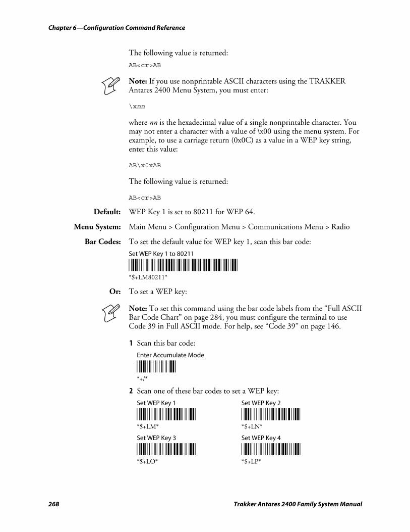
Chapter 6—Configuration Command Reference
268 Trakker Antares 2400 Family System Manual
The following value is returned:
AB<cr>AB
Note: If you use nonprintable ASCII characters using the TRAKKER Antares 2400 Menu System, you must enter:
\xnn
where nn is the hexadecimal value of a single nonprintable character. You may not enter a character with a value of \x00 using the menu system. For example, to use a carriage return (0x0C) as a value in a WEP key string, enter this value:
AB\x0xAB
The following value is returned:
AB<cr>AB
Default: WEP Key 1 is set to 80211 for WEP 64.
Menu System: Main Menu > Configuration Menu > Communications Menu > Radio
Bar Codes: To set the default value for WEP key 1, scan this bar code:
Set WEP Key 1 to 80211
*$+LM80211* *$+LM80211*
Or: To set a WEP key:
Note: To set this command using the bar code labels from the “Full ASCII Bar Code Chart” on page 284, you must configure the terminal to use Code 39 in Full ASCII mode. For help, see “Code 39” on page 146.
1 Scan this bar code:
Enter Accumulate Mode
*+/* *+/*
2 Scan one of these bar codes to set a WEP key:
Set WEP Key 1 Set WEP Key 2
*$+LM* *$+LN* *$+LM* *$+LN*
Set WEP Key 3 Set WEP Key 4
*$+LO* *$+LP* *$+LO* *$+LP*
Chapter 6—Configuration Command Reference
Trakker Antares 2400 Family System Manual 269
3 Scan a value for data from the “Full ASCII Bar Code Chart” on page 284. The WEP key should be five ASCII characters.
4 Scan this bar code:
Exit Accumulate Mode
*-/* *-/*
WEP Transmit Key
Terminals: 2415, 2425, 2435, 2455, 2475, and 2485/6 with 802.11b radios.
Note: The WEP Transmit Key command cannot be manually configured on terminals with the 802.1x security option.
Description: Determines which of the four WEP keys the RF terminal uses to transmit data. You can set this parameter to a value from 1 to 4. The default value is 1, which indicates that the RF terminal uses WEP Key 1. The access point and the RF terminal must use the same WEP transmit key.
Note: You need to enable the WEP Encryption command and set the WEP key values before you can select a WEP transmit key.
Syntax: LLdata
Acceptable values for data are any number from 1 to 4.
Default: 1
Menu System: Main Menu > Configuration Menu > Communications Menu > Radio
Bar Codes: To set the default WEP transmit key, scan this bar code:
Default WEP Transmit Key
*$+LL1* *$+LL1*
Or: To set the WEP transmit key:
1 Scan this bar code:
Enter Accumulate Mode / Set WEP Transmit Key
*+/$+LL* *+/$+LL*
Chapter 6—Configuration Command Reference
270 Trakker Antares 2400 Family System Manual
2 Scan a numeric value for data from these bar codes:
*1* *2* *1* *2*
*3* *4* *3* *4*
3 Scan this bar code:
Exit Accumulate Mode
*-/* *-/*
Trakker Antares 2400 Family System Manual 271
Default Configurations and Command Syntax
This appendix lists the default configuration values and provides a configuration command reference list in alphabetical order by command syntax.
A
Appendix A—Default Configurations and Command Syntax
272 Trakker Antares 2400 Family System Manual
Default Configuration The next tables list the terminal’s default configuration values. You can use the TRAKKER Antares 2400 Menu System to set the terminal to the default configuration. For help, see “Restoring the Terminal’s Default Configuration” on page 30.
Not all configuration commands apply to all terminals. To determine which commands apply to your Trakker Antares® terminal, see “Configuration Commands Listed by Category” starting on page 125.
Bar Code Symbology Default Configuration
Bar Code Symbology
Default Value
Codabar Disabled
Code 11 Disabled
Code 2 of 5 Disabled
Code 39 Full ASCII Code 39 enabled with no check digit
Code 93 Disabled
Code 128 Standard
Interleaved 2 of 5 Disabled
MSI Disabled
PDF417 Disabled
Plessey Disabled
UPC/EAN UPC-A/EAN-13 enabled, UPC-E and EAN-8 enabled, supplementals allowed, transmit check digit, transmit number system digit, and retain leading zero for UPC-A
GTIN Compliance Disabled
Operations Default Configuration
Operations Command Default Value
Append Time Disabled
Automatic Shutoff 0 minutes (disabled)
Beep Duration 150 ms high, 50 ms low (243X) 50 ms high, 50 ms low (241X, 242X, 2455, 246X, 2475, 248X)
Beep Frequency 2400 Hz high, 1400 Hz low (241X) 1900 Hz high, 1050 Hz low (243X) 2400 Hz high, 1200 Hz low (242X, 2455, 2475, 248X)
Beep Volume Very loud
Character Set U.S. ASCII
Command Processing All reader commands enabled
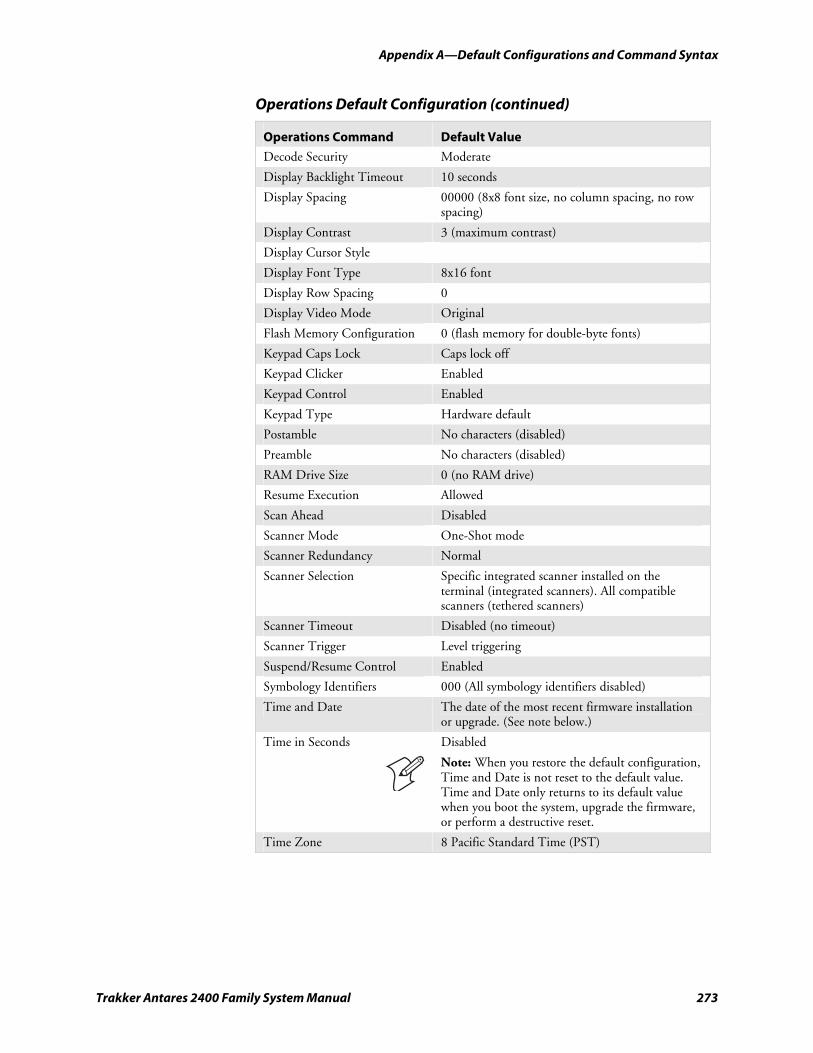
Appendix A—Default Configurations and Command Syntax
Trakker Antares 2400 Family System Manual 273
Operations Default Configuration (continued)
Operations Command Default Value
Decode Security Moderate
Display Backlight Timeout 10 seconds
Display Spacing 00000 (8x8 font size, no column spacing, no row spacing)
Display Contrast 3 (maximum contrast)
Display Cursor Style
Display Font Type 8x16 font
Display Row Spacing 0
Display Video Mode Original
Flash Memory Configuration 0 (flash memory for double-byte fonts)
Keypad Caps Lock Caps lock off
Keypad Clicker Enabled
Keypad Control Enabled
Keypad Type Hardware default
Postamble No characters (disabled)
Preamble No characters (disabled)
RAM Drive Size 0 (no RAM drive)
Resume Execution Allowed
Scan Ahead Disabled
Scanner Mode One-Shot mode
Scanner Redundancy Normal
Scanner Selection Specific integrated scanner installed on the terminal (integrated scanners). All compatible scanners (tethered scanners)
Scanner Timeout Disabled (no timeout)
Scanner Trigger Level triggering
Suspend/Resume Control Enabled
Symbology Identifiers 000 (All symbology identifiers disabled)
Time and Date The date of the most recent firmware installation or upgrade. (See note below.)
Time in Seconds Disabled
Note: When you restore the default configuration, Time and Date is not reset to the default value. Time and Date only returns to its default value when you boot the system, upgrade the firmware, or perform a destructive reset.
Time Zone 8 Pacific Standard Time (PST)
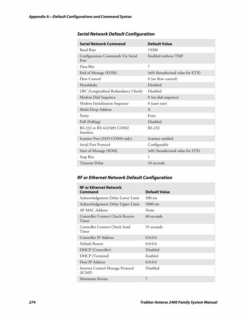
Appendix A—Default Configurations and Command Syntax
274 Trakker Antares 2400 Family System Manual
Serial Network Default Configuration
Serial Network Command Default Value
Baud Rate 19200
Configuration Commands Via Serial Port
Enabled without TMF
Data Bits 7
End of Message (EOM) \x03 (hexadecimal value for ETX)
Flow Control 0 (no flow control)
Handshake Disabled
LRC (Longitudinal Redundancy Check) Disabled
Modem Dial Sequence 0 (no dial sequence)
Modem Initialization Sequence 0 (auto rate)
Multi-Drop Address A
Parity Even
Poll (Polling) Disabled
RS-232 or RS-422/485 COM2 Interface
RS-232
Scanner Port (2455 COM4 only) Scanner enabled
Serial Port Protocol Configurable
Start of Message (SOM) \x02 (hexadecimal value for STX)
Stop Bits 1
Timeout Delay 10 seconds
RF or Ethernet Network Default Configuration
RF or Ethernet Network Command
Default Value
Acknowledgement Delay Lower Limit 300 ms
Acknowledgement Delay Upper Limit 5000 ms
AP MAC Address None
Controller Connect Check Receive Timer
60 seconds
Controller Connect Check Send Timer
35 seconds
Controller IP Address 0.0.0.0
Default Router 0.0.0.0
DHCP (Controller) Disabled
DHCP (Terminal) Enabled
Host IP Address 0.0.0.0
Internet Control Message Protocol (ICMP)
Disabled
Maximum Retries 7
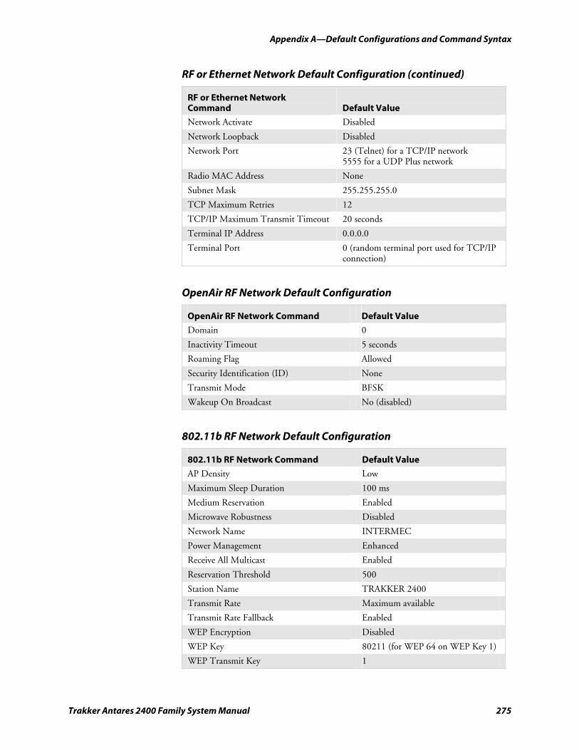
Appendix A—Default Configurations and Command Syntax
Trakker Antares 2400 Family System Manual 275
RF or Ethernet Network Default Configuration (continued)
RF or Ethernet Network Command
Default Value
Network Activate Disabled
Network Loopback Disabled
Network Port 23 (Telnet) for a TCP/IP network 5555 for a UDP Plus network
Radio MAC Address None
Subnet Mask 255.255.255.0
TCP Maximum Retries 12
TCP/IP Maximum Transmit Timeout 20 seconds
Terminal IP Address 0.0.0.0
Terminal Port 0 (random terminal port used for TCP/IP connection)
OpenAir RF Network Default Configuration
OpenAir RF Network Command Default Value
Domain 0
Inactivity Timeout 5 seconds
Roaming Flag Allowed
Security Identification (ID) None
Transmit Mode BFSK
Wakeup On Broadcast No (disabled)
802.11b RF Network Default Configuration
802.11b RF Network Command Default Value
AP Density Low
Maximum Sleep Duration 100 ms
Medium Reservation Enabled
Microwave Robustness Disabled
Network Name INTERMEC
Power Management Enhanced
Receive All Multicast Enabled
Reservation Threshold 500
Station Name TRAKKER 2400
Transmit Rate Maximum available
Transmit Rate Fallback Enabled
WEP Encryption Disabled
WEP Key 80211 (for WEP 64 on WEP Key 1)
WEP Transmit Key 1
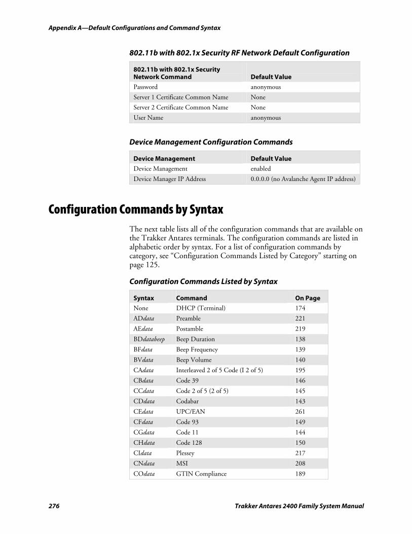
Appendix A—Default Configurations and Command Syntax
276 Trakker Antares 2400 Family System Manual
802.11b with 802.1x Security RF Network Default Configuration
802.11b with 802.1x Security Network Command
Default Value
Password anonymous
Server 1 Certificate Common Name None
Server 2 Certificate Common Name None
User Name anonymous
Device Management Configuration Commands
Device Management Default Value
Device Management enabled
Device Manager IP Address 0.0.0.0 (no Avalanche Agent IP address)
Configuration Commands by Syntax The next table lists all of the configuration commands that are available on the Trakker Antares terminals. The configuration commands are listed in alphabetic order by syntax. For a list of configuration commands by category, see “Configuration Commands Listed by Category” starting on page 125.
Configuration Commands Listed by Syntax
Syntax Command On Page
None DHCP (Terminal) 174
ADdata Preamble 221
AEdata Postamble 219
BDdatabeep Beep Duration 138
BFdata Beep Frequency 139
BVdata Beep Volume 140
CAdata Interleaved 2 of 5 Code (I 2 of 5) 195
CBdata Code 39 146
CCdata Code 2 of 5 (2 of 5) 145
CDdata Codabar 143
CEdata UPC/EAN 261
CFdata Code 93 149
CGdata Code 11 144
CHdata Code 128 150
CIdata Plessey 217
CNdata MSI 208
COdata GTIN Compliance 189
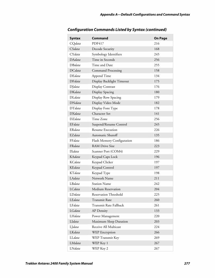
Appendix A—Default Configurations and Command Syntax
Trakker Antares 2400 Family System Manual 277
Configuration Commands Listed by Syntax (continued)
Syntax Command On Page
CQdata PDF417 216
CSdata Decode Security 168
CYdata Symbology Identifiers 245
DAdata Time in Seconds 256
DBdata Time and Date 255
DCdata Command Processing 158
DEdata Append Time 134
DFdata Display Backlight Timeout 175
DJdata Display Contrast 176
DKdata Display Spacing 180
DLdata Display Row Spacing 179 DNdata Display Video Mode 182 DTdata Display Font Type 178 DXdata Character Set 141
DZdata Time Zone 256
EFdata Suspend/Resume Control 245 ERdata Resume Execution 226
EZdata Automatic Shutoff 135
FFdata Flash Memory Configuration 186 FRdata RAM Drive Size 223 IXdata Scanner Port (COM4) 229
KAdata Keypad Caps Lock 196
KCdata Keypad Clicker 197
KEdata Keypad Control 197
KTdata Keypad Type 198 LAdata Network Name 211 LBdata Station Name 242
LCdata Medium Reservation 204
LDdata Reservation Threshold 225
LEdata Transmit Rate 260
LFdata Transmit Rate Fallback 261
LGdata AP Density 133
LHdata Power Management 220
LIdata Maximum Sleep Duration 203
LJdata Receive All Multicast 224
LKdata WEP Encryption 266
LLdata WEP Transmit Key 269
LMdata WEP Key 1 267
LNdata WEP Key 2 267
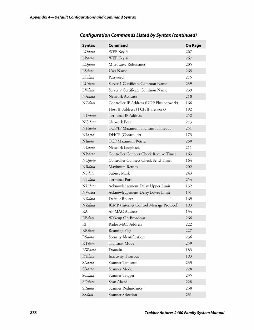
Appendix A—Default Configurations and Command Syntax
278 Trakker Antares 2400 Family System Manual
Configuration Commands Listed by Syntax (continued)
Syntax Command On Page
LOdata WEP Key 3 267
LPdata WEP Key 4 267
LQdata Microwave Robustness 205
LSdata User Name 265
LTdata Password 215
LUdata Server 1 Certificate Common Name 239
LVdata Server 2 Certificate Common Name 239
NAdata Network Activate 210
NCdata Controller IP Address (UDP Plus network) 166
Host IP Address (TCP/IP network) 192
NDdata Terminal IP Address 252
NGdata Network Port 213
NHdata TCP/IP Maximum Transmit Timeout 251
NIdata DHCP (Controller) 173
NJdata TCP Maximum Retries 250 NLdata Network Loopback 211
NPdata Controller Connect Check Receive Timer 163 NQdata Controller Connect Check Send Timer 164 NRdata Maximum Retries 202 NSdata Subnet Mask 243
NTdata Terminal Port 254
NUdata Acknowledgement Delay Upper Limit 132 NVdata Acknowledgement Delay Lower Limit 131
NXdata Default Router 169
NZdata ICMP (Internet Control Message Protocol) 193
RA AP MAC Address 134
RBdata Wakeup On Broadcast 266
RI Radio MAC Address 222
RRdata Roaming Flag 227 RSdata Security Identification 236
RTdata Transmit Mode 259 RWdata Domain 183
RYdata Inactivity Timeout 193 SAdata Scanner Timeout 233
SBdata Scanner Mode 228
SCdata Scanner Trigger 235
SDdata Scan Ahead 228
SRdata Scanner Redundancy 230
SSdata Scanner Selection 231
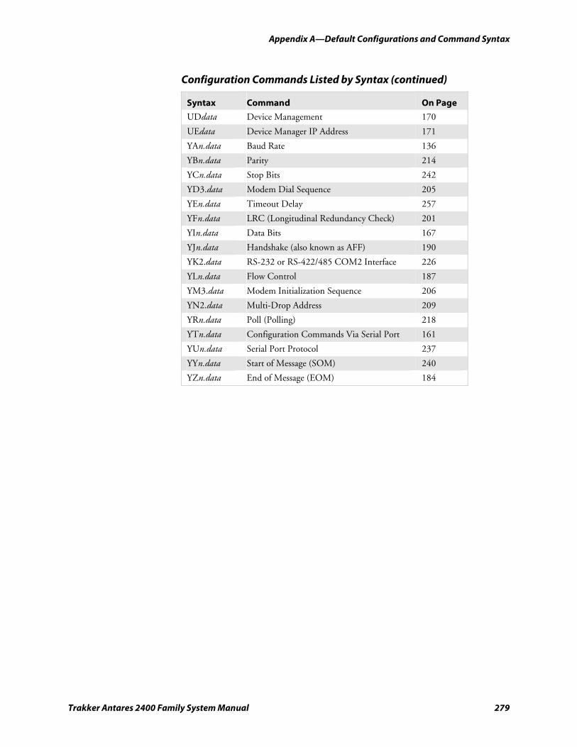
Appendix A—Default Configurations and Command Syntax
Trakker Antares 2400 Family System Manual 279
Configuration Commands Listed by Syntax (continued)
Syntax Command On Page
UDdata Device Management 170
UEdata Device Manager IP Address 171 YAn.data Baud Rate 136 YBn.data Parity 214 YCn.data Stop Bits 242 YD3.data Modem Dial Sequence 205
YEn.data Timeout Delay 257 YFn.data LRC (Longitudinal Redundancy Check) 201 YIn.data Data Bits 167 YJn.data Handshake (also known as AFF) 190 YK2.data RS-232 or RS-422/485 COM2 Interface 226 YLn.data Flow Control 187 YM3.data Modem Initialization Sequence 206 YN2.data Multi-Drop Address 209
YRn.data Poll (Polling) 218 YTn.data Configuration Commands Via Serial Port 161 YUn.data Serial Port Protocol 237
YYn.data Start of Message (SOM) 240 YZn.data End of Message (EOM) 184

Appendix A—Default Configurations and Command Syntax
280 Trakker Antares 2400 Family System Manual
Trakker Antares 2400 Family System Manual 281
Full ASCII Charts
This appendix contains the full ASCII table and the full ASCII chart of Code 39 bar code labels.
B
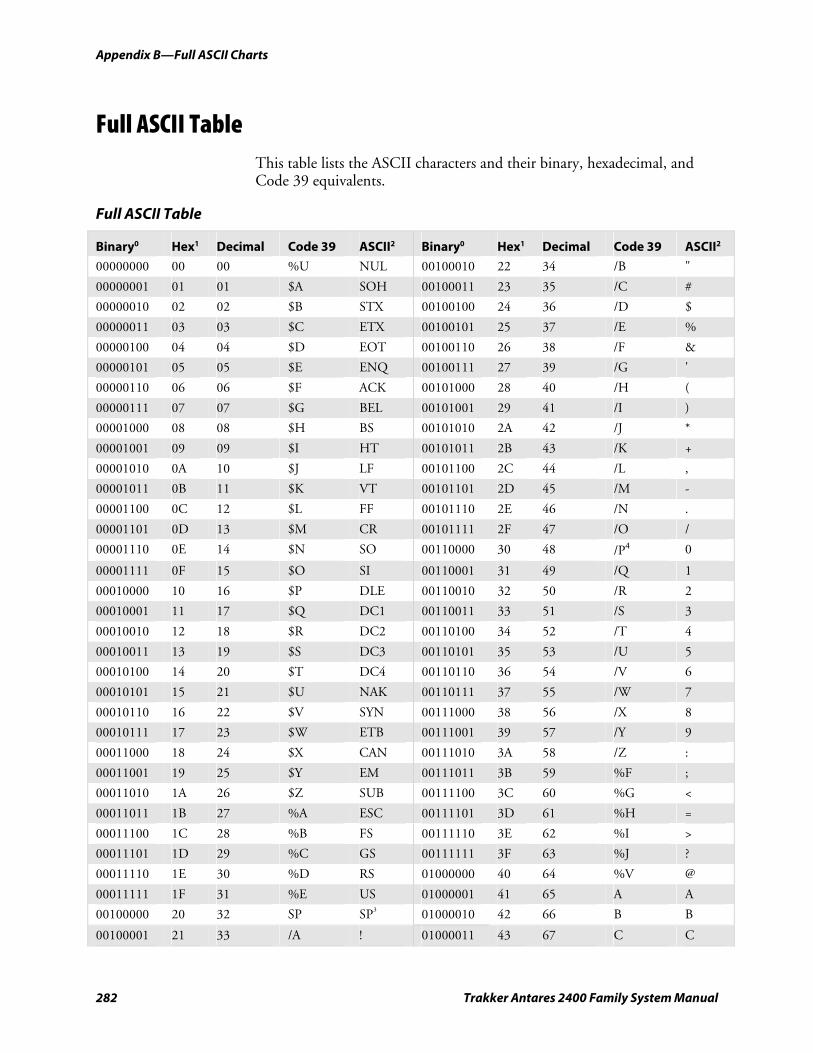
Appendix B—Full ASCII Charts
282 Trakker Antares 2400 Family System Manual
Full ASCII Table This table lists the ASCII characters and their binary, hexadecimal, and Code 39 equivalents.
Full ASCII Table
Binary0 Hex1 Decimal Code 39 ASCII2 Binary0 Hex1 Decimal Code 39 ASCII2
00000000 00 00 %U NUL 00100010 22 34 /B "
00000001 01 01 $A SOH 00100011 23 35 /C #
00000010 02 02 $B STX 00100100 24 36 /D $
00000011 03 03 $C ETX 00100101 25 37 /E %
00000100 04 04 $D EOT 00100110 26 38 /F &
00000101 05 05 $E ENQ 00100111 27 39 /G '
00000110 06 06 $F ACK 00101000 28 40 /H (
00000111 07 07 $G BEL 00101001 29 41 /I )
00001000 08 08 $H BS 00101010 2A 42 /J *
00001001 09 09 $I HT 00101011 2B 43 /K +
00001010 0A 10 $J LF 00101100 2C 44 /L ,
00001011 0B 11 $K VT 00101101 2D 45 /M -
00001100 0C 12 $L FF 00101110 2E 46 /N .
00001101 0D 13 $M CR 00101111 2F 47 /O /
00001110 0E 14 $N SO 00110000 30 48 /P4 0
00001111 0F 15 $O SI 00110001 31 49 /Q 1
00010000 10 16 $P DLE 00110010 32 50 /R 2
00010001 11 17 $Q DC1 00110011 33 51 /S 3
00010010 12 18 $R DC2 00110100 34 52 /T 4
00010011 13 19 $S DC3 00110101 35 53 /U 5
00010100 14 20 $T DC4 00110110 36 54 /V 6
00010101 15 21 $U NAK 00110111 37 55 /W 7
00010110 16 22 $V SYN 00111000 38 56 /X 8
00010111 17 23 $W ETB 00111001 39 57 /Y 9
00011000 18 24 $X CAN 00111010 3A 58 /Z :
00011001 19 25 $Y EM 00111011 3B 59 %F ;
00011010 1A 26 $Z SUB 00111100 3C 60 %G <
00011011 1B 27 %A ESC 00111101 3D 61 %H =
00011100 1C 28 %B FS 00111110 3E 62 %I >
00011101 1D 29 %C GS 00111111 3F 63 %J ?
00011110 1E 30 %D RS 01000000 40 64 %V @
00011111 1F 31 %E US 01000001 41 65 A A
00100000 20 32 SP SP3 01000010 42 66 B B
00100001 21 33 /A ! 01000011 43 67 C C
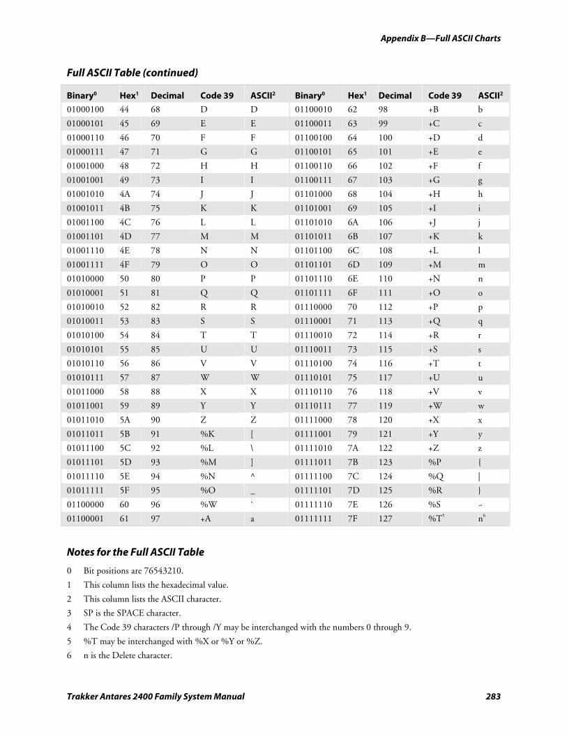
Appendix B—Full ASCII Charts
Trakker Antares 2400 Family System Manual 283
Full ASCII Table (continued)
Binary0 Hex1 Decimal Code 39 ASCII2 Binary0 Hex1 Decimal Code 39 ASCII2
01000100 44 68 D D 01100010 62 98 +B b
01000101 45 69 E E 01100011 63 99 +C c
01000110 46 70 F F 01100100 64 100 +D d
01000111 47 71 G G 01100101 65 101 +E e
01001000 48 72 H H 01100110 66 102 +F f
01001001 49 73 I I 01100111 67 103 +G g
01001010 4A 74 J J 01101000 68 104 +H h
01001011 4B 75 K K 01101001 69 105 +I i
01001100 4C 76 L L 01101010 6A 106 +J j
01001101 4D 77 M M 01101011 6B 107 +K k
01001110 4E 78 N N 01101100 6C 108 +L l
01001111 4F 79 O O 01101101 6D 109 +M m
01010000 50 80 P P 01101110 6E 110 +N n
01010001 51 81 Q Q 01101111 6F 111 +O o
01010010 52 82 R R 01110000 70 112 +P p
01010011 53 83 S S 01110001 71 113 +Q q
01010100 54 84 T T 01110010 72 114 +R r
01010101 55 85 U U 01110011 73 115 +S s
01010110 56 86 V V 01110100 74 116 +T t
01010111 57 87 W W 01110101 75 117 +U u
01011000 58 88 X X 01110110 76 118 +V v
01011001 59 89 Y Y 01110111 77 119 +W w
01011010 5A 90 Z Z 01111000 78 120 +X x
01011011 5B 91 %K [ 01111001 79 121 +Y y
01011100 5C 92 %L \ 01111010 7A 122 +Z z
01011101 5D 93 %M ] 01111011 7B 123 %P {
01011110 5E 94 %N ^ 01111100 7C 124 %Q |
01011111 5F 95 %O _ 01111101 7D 125 %R }
01100000 60 96 %W ` 01111110 7E 126 %S ~
01100001 61 97 +A a 01111111 7F 127 %T5 n6
Notes for the Full ASCII Table
0 Bit positions are 76543210.
1 This column lists the hexadecimal value.
2 This column lists the ASCII character.
3 SP is the SPACE character.
4 The Code 39 characters /P through /Y may be interchanged with the numbers 0 through 9.
5 %T may be interchanged with %X or %Y or %Z.
6 n is the Delete character.
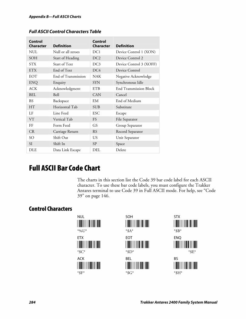
Appendix B—Full ASCII Charts
284 Trakker Antares 2400 Family System Manual
Full ASCII Control Characters Table
Control Character
Definition
Control Character
Definition
NUL Null or all zeroes DC1 Device Control 1 (XON)
SOH Start of Heading DC2 Device Control 2
STX Start of Text DC3 Device Control 3 (XOFF)
ETX End of Text DC4 Device Control
EOT End of Transmission NAK Negative Acknowledge
ENQ Enquiry SYN Synchronous Idle
ACK Acknowledgment ETB End Transmission Block
BEL Bell CAN Cancel
BS Backspace EM End of Medium
HT Horizontal Tab SUB Substitute
LF Line Feed ESC Escape
VT Vertical Tab FS File Separator
FF Form Feed GS Group Separator
CR Carriage Return RS Record Separator
SO Shift Out US Unit Separator
SI Shift In SP Space
DLE Data Link Escape DEL Delete
Full ASCII Bar Code Chart The charts in this section list the Code 39 bar code label for each ASCII character. To use these bar code labels, you must configure the Trakker Antares terminal to use Code 39 in Full ASCII mode. For help, see “Code 39” on page 146.
Control Characters NUL SOH STX
*%U* *$A* *$B* *%U* *$A* *$B*
ETX EOT ENQ
*$C* *$D* *$E* *$C* *$D* *$E*
ACK BEL BS
*$F* *$G* *$H* *$F* *$G* *$H*
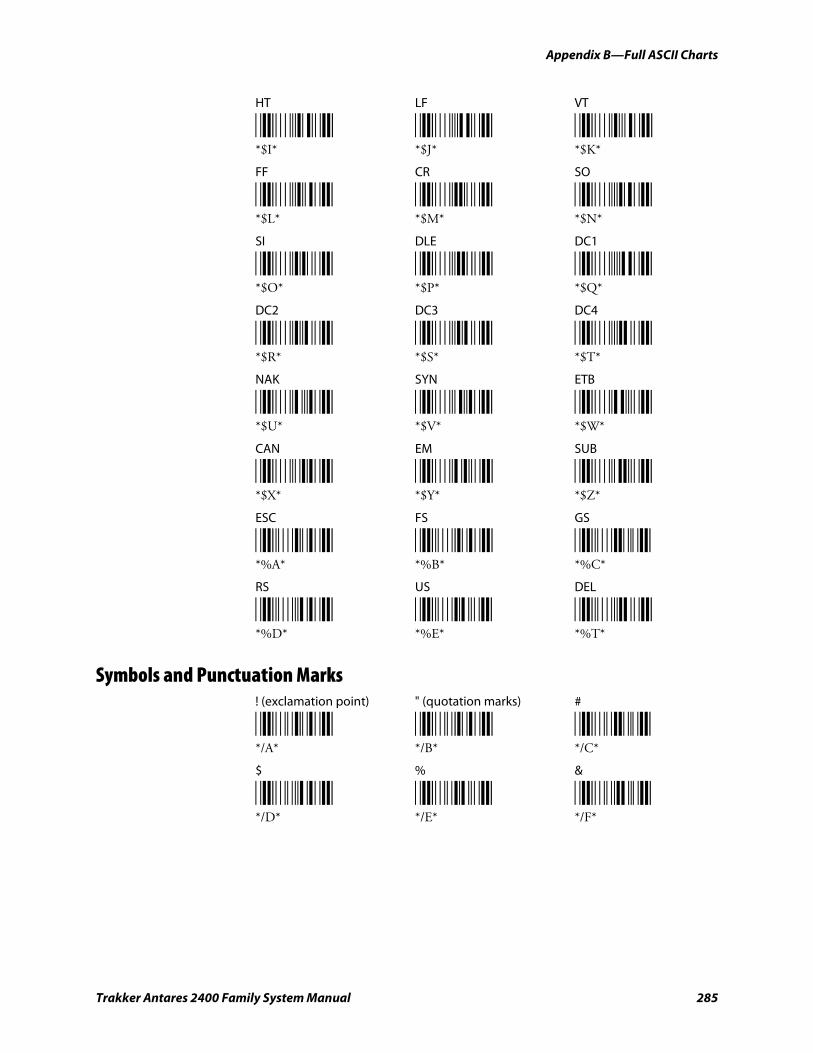
Appendix B—Full ASCII Charts
Trakker Antares 2400 Family System Manual 285
HT LF VT
*$I* *$J* *$K* *$I* *$J* *$K*
FF CR SO
*$L* *$M* *$N* *$L* *$M* *$N*
SI DLE DC1
*$O* *$P* *$Q* *$O* *$P* *$Q*
DC2 DC3 DC4
*$R* *$S* *$T* *$R* *$S* *$T*
NAK SYN ETB
*$U* *$V* *$W* *$U* *$V* *$W*
CAN EM SUB
*$X* *$Y* *$Z* *$X* *$Y* *$Z*
ESC FS GS
*%A* *%B* *%C* *%A* *%B* *%C*
RS US DEL
*%D* *%E* *%T* *%D* *%E* *%T*
Symbols and Punctuation Marks ! (exclamation point) " (quotation marks) #
*/A* */B* */C* */A* */B* */C*
$ % &
*/D* */E* */F* */D* */E* */F*
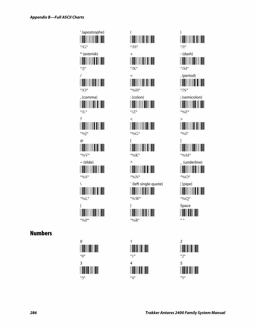
Appendix B—Full ASCII Charts
286 Trakker Antares 2400 Family System Manual
' (apostrophe) ( )
*/G* */H* */I* */G* */H* */I*
* (asterisk) + - (dash)
*/J* */K* */M* */J* */K* */M*
/ = . (period)
*/O* *%H* */N* */O* *%H* */N*
, (comma) : (colon) ; (semicolon)
*/L* */Z* *%F* */L* */Z* *%F*
? < >
*%J* *%G* *%I* *%J* *%G* *%I*
@ [ ]
*%V* *%K* *%M* *%V* *%K* *%M*
~ (tilde) ^ _ (underline)
*%S* *%N* *%O* *%S* *%N* *%O*
\ ` (left single quote) ¦ (pipe)
*%L* *%W* *%Q* *%L* *%W* *%Q*
{ } Space
*%P* *%R* * * *%P* *%R* * *
Numbers 0 1 2
*0* *1* *2* *0* *1* *2*
3 4 5
*3* *4* *5* *3* *4* *5*
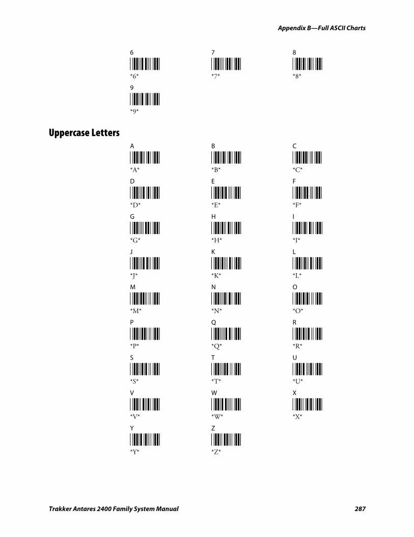
Appendix B—Full ASCII Charts
Trakker Antares 2400 Family System Manual 287
6 7 8
*6* *7* *8* *6* *7* *8*
9
*9* *9*
Uppercase Letters A B C
*A* *B* *C* *A* *B* *C*
D E F
*D* *E* *F* *D* *E* *F*
G H I
*G* *H* *I* *G* *H* *I*
J K L
*J* *K* *L* *J* *K* *L*
M N O
*M* *N* *O* *M* *N* *O*
P Q R
*P* *Q* *R* *P* *Q* *R*
S T U
*S* *T* *U* *S* *T* *U*
V W X
*V* *W* *X* *V* *W* *X*
Y Z
*Y* *Z* *Y* *Z*
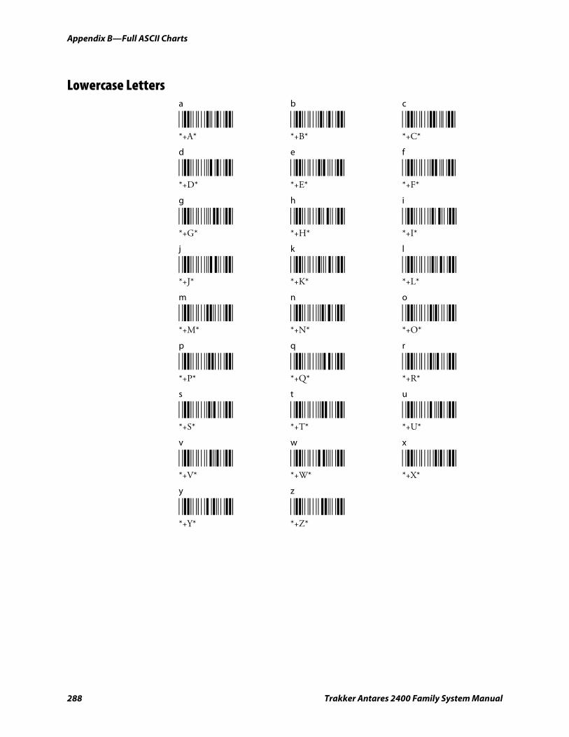
Appendix B—Full ASCII Charts
288 Trakker Antares 2400 Family System Manual
Lowercase Letters a b c
*+A* *+B* *+C* *+A* *+B* *+C*
d e f
*+D* *+E* *+F* *+D* *+E* *+F*
g h i
*+G* *+H* *+I* *+G* *+H* *+I*
j k l
*+J* *+K* *+L* *+J* *+K* *+L*
m n o
*+M* *+N* *+O* *+M* *+N* *+O*
p q r
*+P* *+Q* *+R* *+P* *+Q* *+R*
s t u
*+S* *+T* *+U* *+S* *+T* *+U*
v w x
*+V* *+W* *+X* *+V* *+W* *+X*
y z
*+Y* *+Z* *+Y* *+Z*
Trakker Antares 2400 Family System Manual 289
International Character Support
This appendix lists some of the international characters that the terminal can display and includes the:
• English and Western European font set
• Japanese Katakana font set.
C
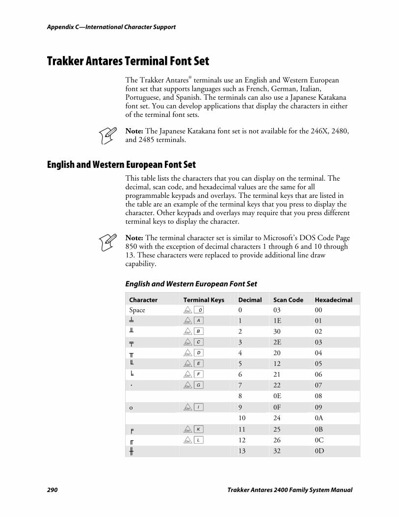
Appendix C—International Character Support
290 Trakker Antares 2400 Family System Manual
Trakker Antares Terminal Font Set The Trakker Antares® terminals use an English and Western European font set that supports languages such as French, German, Italian, Portuguese, and Spanish. The terminals can also use a Japanese Katakana font set. You can develop applications that display the characters in either of the terminal font sets.
Note: The Japanese Katakana font set is not available for the 246X, 2480, and 2485 terminals.
English and Western European Font Set This table lists the characters that you can display on the terminal. The decimal, scan code, and hexadecimal values are the same for all programmable keypads and overlays. The terminal keys that are listed in the table are an example of the terminal keys that you press to display the character. Other keypads and overlays may require that you press different terminal keys to display the character.
Note: The terminal character set is similar to Microsoft’s DOS Code Page 850 with the exception of decimal characters 1 through 6 and 10 through 13. These characters were replaced to provide additional line draw capability.
English and Western European Font Set
Character Terminal Keys Decimal Scan Code Hexadecimal
Space c 0 0 03 00
╧ c A 1 1E 01
╨ c B 2 30 02
╤ c C 3 2E 03
╥ c D 4 20 04
╙ c E 5 12 05
╘ c F 6 21 06
· c G 7 22 07
8 0E 08
o c I 9 0F 09
10 24 0A
╒ c K 11 25 0B
╓ c L 12 26 0C
╫ 13 32 0D
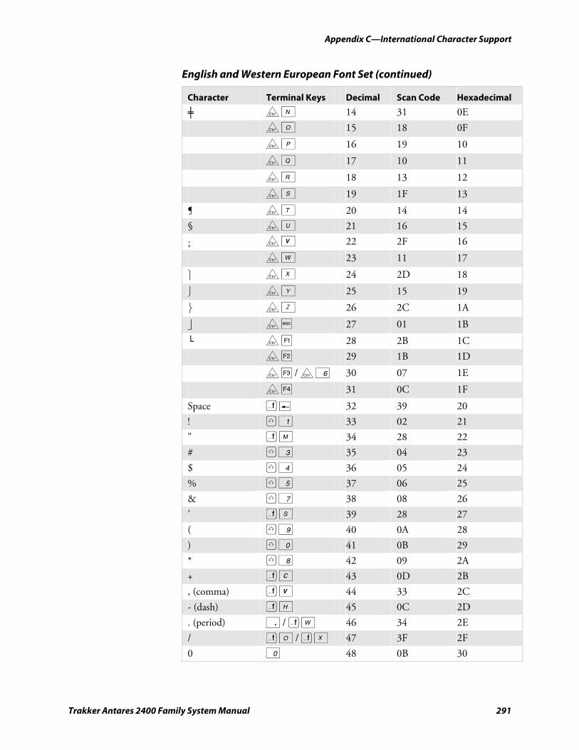
Appendix C—International Character Support
Trakker Antares 2400 Family System Manual 291
English and Western European Font Set (continued)
Character Terminal Keys Decimal Scan Code Hexadecimal
╪ c N 14 31 0E
c O 15 18 0F
c P 16 19 10
c Q 17 10 11
c R 18 13 12
c S 19 1F 13
¶ c T 20 14 14
§ c U 21 16 15
; c V 22 2F 16
c W 23 11 17
⎫ c X 24 2D 18
⎭ c Y 25 15 19
⎬ c Z 26 2C 1A
⎦ c • 27 01 1B
└ c ¡ 28 2B 1C
c ¢ 29 1B 1D
c £ / c 6 30 07 1E
c § 31 0C 1F
Space ) « 32 39 20
! ? 1 33 02 21
" ) M 34 28 22
# ? 3 35 04 23
$ ? 4 36 05 24
% ? 5 37 06 25
& ? 7 38 08 26
’ ) S 39 28 27
( ? 9 40 0A 28
) ? 0 41 0B 29
* ? 8 42 09 2A
+ ) C 43 0D 2B
, (comma) ) V 44 33 2C
- (dash) ) H 45 0C 2D
. (period) . / ) W 46 34 2E
/ ) O / ) X 47 3F 2F
0 0 48 0B 30
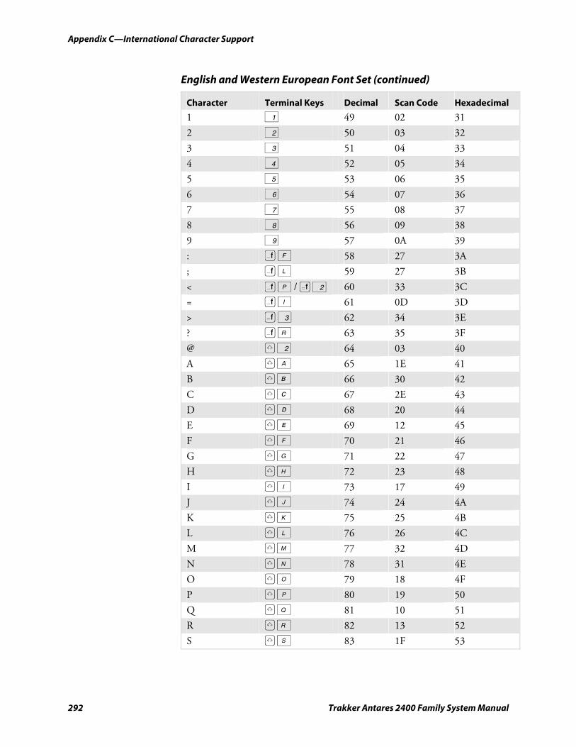
Appendix C—International Character Support
292 Trakker Antares 2400 Family System Manual
English and Western European Font Set (continued)
Character Terminal Keys Decimal Scan Code Hexadecimal
1 1 49 02 31
2 2 50 03 32
3 3 51 04 33
4 4 52 05 34
5 5 53 06 35
6 6 54 07 36
7 7 55 08 37
8 8 56 09 38
9 9 57 0A 39
: ) F 58 27 3A
; ) L 59 27 3B
< ) P / ( 2 60 33 3C
= ) I 61 0D 3D
> ( 3 62 34 3E
? ) R 63 35 3F
@ ? 2 64 03 40
A ? A 65 1E 41
B ? B 66 30 42
C ? C 67 2E 43
D ? D 68 20 44
E ? E 69 12 45
F ? F 70 21 46
G ? G 71 22 47
H ? H 72 23 48
I ? I 73 17 49
J ? J 74 24 4A
K ? K 75 25 4B
L ? L 76 26 4C
M ? M 77 32 4D
N ? N 78 31 4E
O ? O 79 18 4F
P ? P 80 19 50
Q ? Q 81 10 51
R ? R 82 13 52
S ? S 83 1F 53

Appendix C—International Character Support
Trakker Antares 2400 Family System Manual 293
English and Western European Font Set (continued)
Character Terminal Keys Decimal Scan Code Hexadecimal
T ? T 84 14 54
U ? U 85 16 55
V ? V 86 2F 56
W ? W 87 11 57
X ? X 88 2D 58
Y ? Y 89 15 59
Z ? Z 90 2C 5A
[ ) J 91 1A 5B
\ ) T 92 2B 5C
] ) K 93 1B 5D
^ ? 6 94 07 5E
_ (underline) ) B 95 0C 5F
` ) G 96 29 60
a A 97 1E 61
b B 98 30 62
c C 99 2E 63
d D 100 20 64
e E 101 12 65
f F 102 21 66
g G 103 22 67
h H 104 23 68
i I 105 17 69
j J 106 24 6A
k K 107 25 6B
l L 108 26 6C
m M 109 32 6D
n N 110 31 6E
o O 111 18 6F
p P 112 19 70
q Q 113 10 71
r R 114 13 72
s S 115 1F 73
t T 116 14 74
u U 117 16 75
v V 118 2F 76
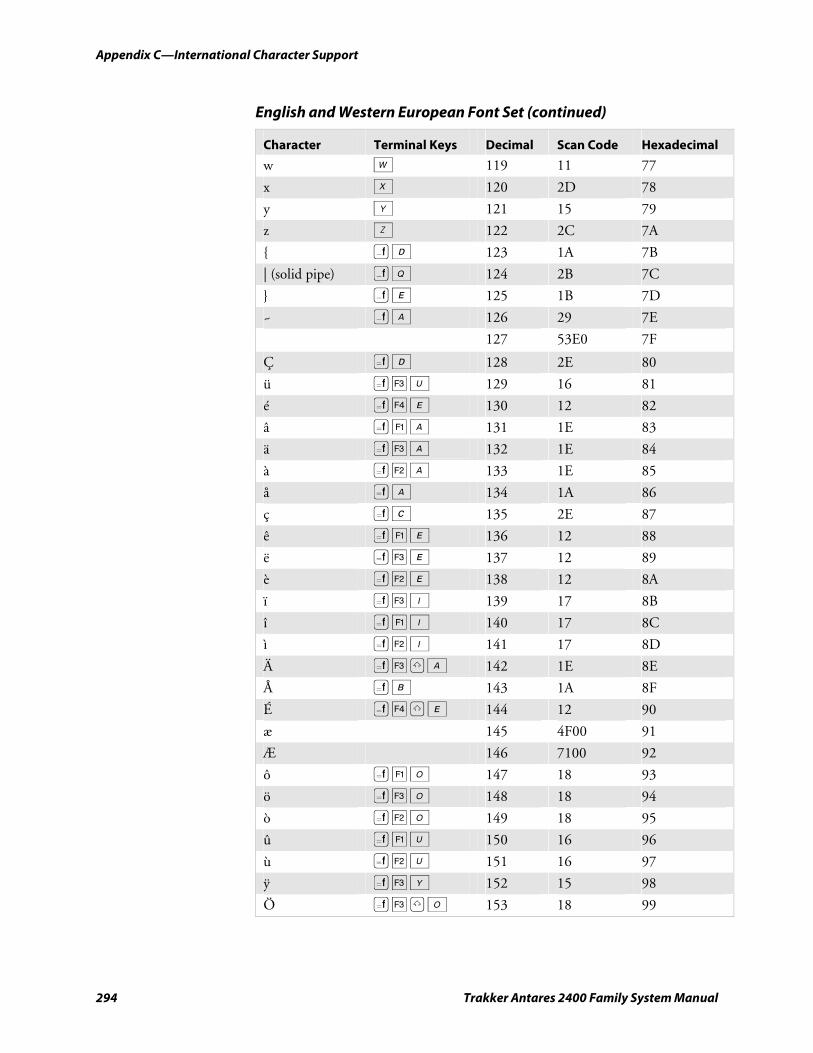
Appendix C—International Character Support
294 Trakker Antares 2400 Family System Manual
English and Western European Font Set (continued)
Character Terminal Keys Decimal Scan Code Hexadecimal
w W 119 11 77
x X 120 2D 78
y Y 121 15 79
z Z 122 2C 7A
{ ) D 123 1A 7B
| (solid pipe) ) Q 124 2B 7C
} ) E 125 1B 7D
~ ) A 126 29 7E
127 53E0 7F
Ç ( D 128 2E 80
ü ( £ U 129 16 81
é ( § E 130 12 82
â ( ¡ A 131 1E 83
ä ( £ A 132 1E 84
à ( ¢ A 133 1E 85
å ( A 134 1A 86
ç ( C 135 2E 87
ê ( ¡ E 136 12 88
ë ( £ E 137 12 89
è ( ¢ E 138 12 8A
ï ( £ I 139 17 8B
î ( ¡ I 140 17 8C
ì ( ¢ I 141 17 8D
Ä ( £ ? A 142 1E 8E
Å ( B 143 1A 8F
É ( § ? E 144 12 90
æ 145 4F00 91
Æ 146 7100 92
ô ( ¡ O 147 18 93
ö ( £ O 148 18 94
ò ( ¢ O 149 18 95
û ( ¡ U 150 16 96
ù ( ¢ U 151 16 97
ÿ ( £ Y 152 15 98
Ö ( £ ? O 153 18 99
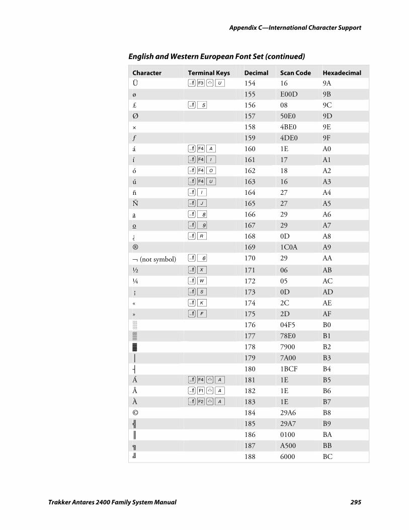
Appendix C—International Character Support
Trakker Antares 2400 Family System Manual 295
English and Western European Font Set (continued)
Character Terminal Keys Decimal Scan Code Hexadecimal
Ü ( £ ? U 154 16 9A
ø 155 E00D 9B
£ ( 5 156 08 9C
Ø 157 50E0 9D
× 158 4BE0 9E
ƒ 159 4DE0 9F
á ( § A 160 1E A0
í ( § I 161 17 A1
ó ( § O 162 18 A2
ú ( § U 163 16 A3
ñ ( I 164 27 A4
Ñ ( J 165 27 A5
a ( 8 166 29 A6
o ( 9 167 29 A7
¿ ( R 168 0D A8
® 169 1C0A A9
¬ (not symbol) ( 6 170 29 AA
½ ( X 171 06 AB
¼ ( W 172 05 AC
¡ ( S 173 0D AD
« ( K 174 2C AE
» ( F 175 2D AF
░ 176 04F5 B0
▒ 177 78E0 B1
▓ 178 7900 B2
│ 179 7A00 B3
┤ 180 1BCF B4
Á ( § ? A 181 1E B5
 ( ¡ ? A 182 1E B6
À ( ¢ ? A 183 1E B7
© 184 29A6 B8
╣ 185 29A7 B9
║ 186 0100 BA
╗ 187 A500 BB
╝ 188 6000 BC
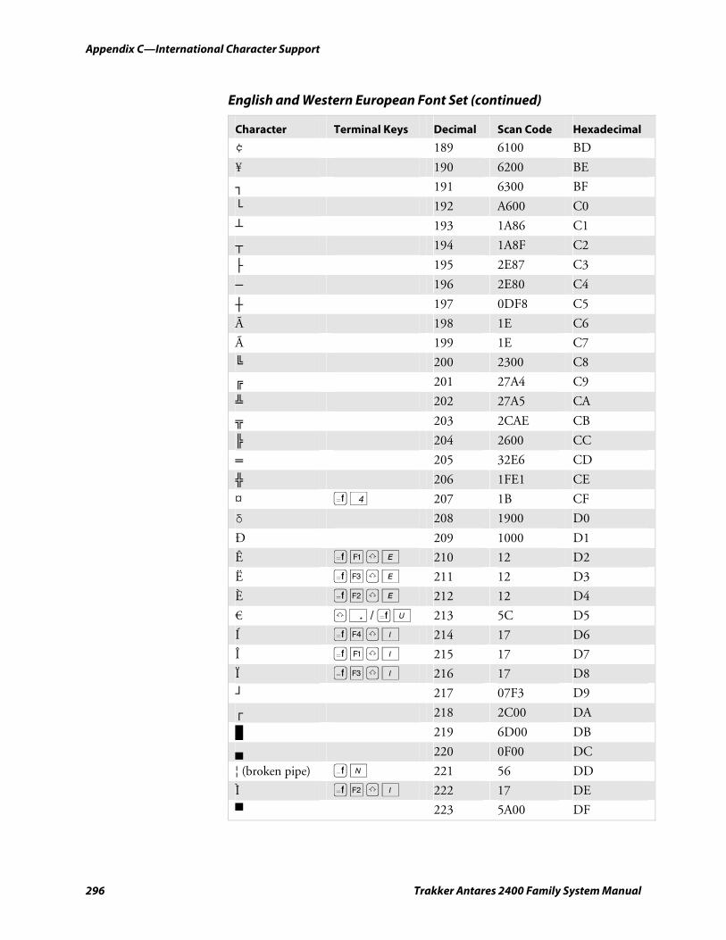
Appendix C—International Character Support
296 Trakker Antares 2400 Family System Manual
English and Western European Font Set (continued)
Character Terminal Keys Decimal Scan Code Hexadecimal
¢ 189 6100 BD
¥ 190 6200 BE
┐ 191 6300 BF
└ 192 A600 C0
┴ 193 1A86 C1
┬ 194 1A8F C2
├ 195 2E87 C3
─ 196 2E80 C4
┼ 197 0DF8 C5
à 198 1E C6
à 199 1E C7
╚ 200 2300 C8
╔ 201 27A4 C9
╩ 202 27A5 CA
╦ 203 2CAE CB
╠ 204 2600 CC
═ 205 32E6 CD
╬ 206 1FE1 CE
¤ ( 4 207 1B CF
δ 208 1900 D0
Ð 209 1000 D1
Ê ( ¡ ? E 210 12 D2
Ë ( £ ? E 211 12 D3
È ( ¢ ? E 212 12 D4
€ ? . / ( U 213 5C D5
Í ( § ? I 214 17 D6
Î ( ¡ ? I 215 17 D7
Ï ( £ ? I 216 17 D8
┘ 217 07F3 D9
┌ 218 2C00 DA
█ 219 6D00 DB
▄ 220 0F00 DC
¦ (broken pipe) ) N 221 56 DD
Ì ( ¢ ? I 222 17 DE
▀ 223 5A00 DF
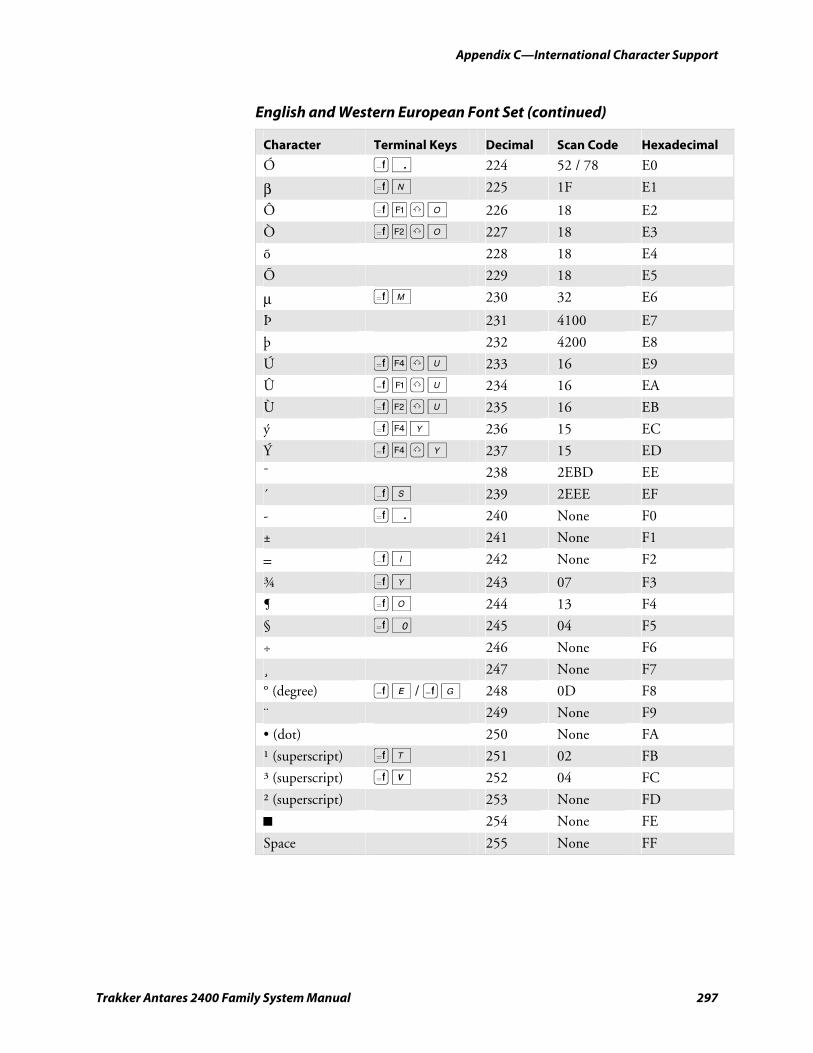
Appendix C—International Character Support
Trakker Antares 2400 Family System Manual 297
English and Western European Font Set (continued)
Character Terminal Keys Decimal Scan Code Hexadecimal
Ó ) . 224 52 / 78 E0
β ( N 225 1F E1
Ô ( ¡ ? O 226 18 E2
Ò ( ¢ ? O 227 18 E3
õ 228 18 E4
Õ 229 18 E5
µ ( M 230 32 E6
Þ 231 4100 E7
þ 232 4200 E8
Ú ( § ? U 233 16 E9
Û ( ¡ ? U 234 16 EA
Ù ( ¢ ? U 235 16 EB
ý ( § Y 236 15 EC
Ý ( § ? Y 237 15 ED
¯ 238 2EBD EE
´ ) S 239 2EEE EF
- ( . 240 None F0
± 241 None F1
= ) I 242 None F2
¾ ( Y 243 07 F3
¶ ( O 244 13 F4
§ ( 0 245 04 F5
÷ 246 None F6
¸ 247 None F7
° (degree) ( E / ( G 248 0D F8
¨ 249 None F9
• (dot) 250 None FA
¹ (superscript) ( T 251 02 FB
³ (superscript) ( V 252 04 FC
² (superscript) 253 None FD
■ 254 None FE
Space 255 None FF
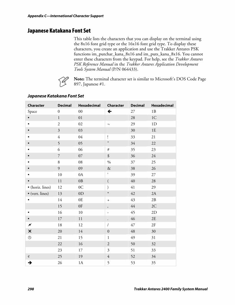
Appendix C—International Character Support
298 Trakker Antares 2400 Family System Manual
Japanese Katakana Font Set This table lists the characters that you can display on the terminal using the 8x16 font grid type or the 16x16 font grid type. To display these characters, you create an application and use the Trakker Antares PSK functions im_putchar_kana_8x16 and im_puts_kana_8x16. You cannot enter these characters from the keypad. For help, see the Trakker Antares PSK Reference Manual in the Trakker Antares Application Development Tools System Manual (P/N 064433).
Note: The terminal character set is similar to Microsoft’s DOS Code Page 897, Japanese #1.
Japanese Katakana Font Set
Character Decimal Hexadecimal Character Decimal Hexadecimal
Space 0 00 27 1B
• 1 01 28 1C
• 2 02 ¬ 29 1D
• 3 03 30 1E
• 4 04 ! 33 21
• 5 05 " 34 22
• 6 06 # 35 23
• 7 07 $ 36 24
• 8 08 % 37 25
• 9 09 & 38 26
• 10 0A ’ 39 27
• 11 0B ( 40 28
• (horiz. lines) 12 0C ) 41 29
• (vert. lines) 13 0D * 42 2A
• 14 0E + 43 2B
15 0F , 44 2C
• 16 10 - 45 2D
• 17 11 . 46 2E
18 12 / 47 2F
20 14 0 48 30
21 15 1 49 31
22 16 2 50 32
23 17 3 51 33
¢ 25 19 4 52 34
26 1A 5 53 35
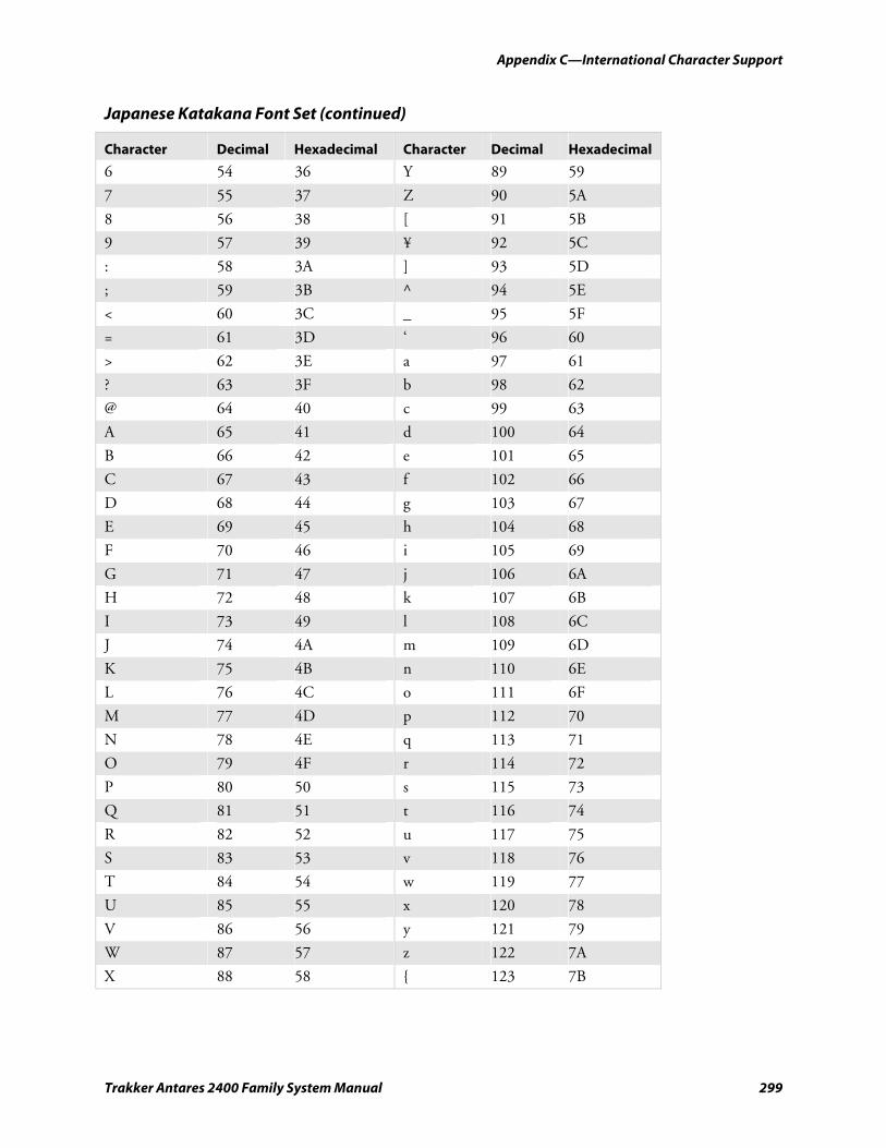
Appendix C—International Character Support
Trakker Antares 2400 Family System Manual 299
Japanese Katakana Font Set (continued)
Character Decimal Hexadecimal Character Decimal Hexadecimal
6 54 36 Y 89 59
7 55 37 Z 90 5A
8 56 38 [ 91 5B
9 57 39 ¥ 92 5C
: 58 3A ] 93 5D
; 59 3B ^ 94 5E
< 60 3C _ 95 5F
= 61 3D ‘ 96 60
> 62 3E a 97 61
? 63 3F b 98 62
@ 64 40 c 99 63
A 65 41 d 100 64
B 66 42 e 101 65
C 67 43 f 102 66
D 68 44 g 103 67
E 69 45 h 104 68
F 70 46 i 105 69
G 71 47 j 106 6A
H 72 48 k 107 6B
I 73 49 l 108 6C
J 74 4A m 109 6D
K 75 4B n 110 6E
L 76 4C o 111 6F
M 77 4D p 112 70
N 78 4E q 113 71
O 79 4F r 114 72
P 80 50 s 115 73
Q 81 51 t 116 74
R 82 52 u 117 75
S 83 53 v 118 76
T 84 54 w 119 77
U 85 55 x 120 78
V 86 56 y 121 79
W 87 57 z 122 7A
X 88 58 { 123 7B
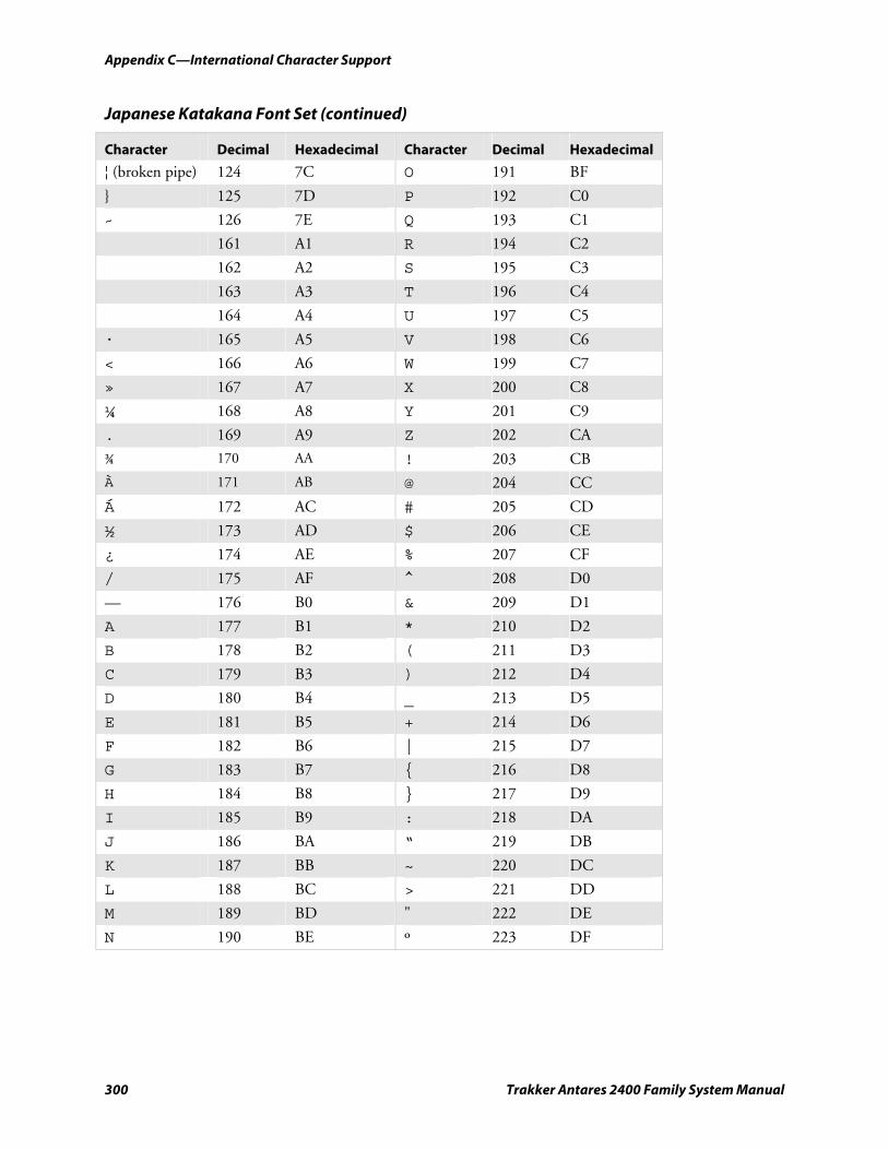
Appendix C—International Character Support
300 Trakker Antares 2400 Family System Manual
Japanese Katakana Font Set (continued)
Character Decimal Hexadecimal Character Decimal Hexadecimal
¦ (broken pipe) 124 7C O 191 BF
} 125 7D P 192 C0
~ 126 7E Q 193 C1
161 A1 R 194 C2
162 A2 S 195 C3
163 A3 T 196 C4
164 A4 U 197 C5
· 165 A5 V 198 C6
< 166 A6 W 199 C7
» 167 A7 X 200 C8
¼ 168 A8 Y 201 C9
. 169 A9 Z 202 CA
¾ 170 AA ! 203 CB
À 171 AB @ 204 CC
Á 172 AC # 205 CD
½ 173 AD $ 206 CE
¿ 174 AE % 207 CF
/ 175 AF ^ 208 D0
— 176 B0 & 209 D1
A 177 B1 * 210 D2
B 178 B2 ( 211 D3
C 179 B3 ) 212 D4
D 180 B4 _ 213 D5
E 181 B5 + 214 D6
F 182 B6 | 215 D7
G 183 B7 { 216 D8
H 184 B8 } 217 D9
I 185 B9 : 218 DA
J 186 BA “ 219 DB
K 187 BB ~ 220 DC
L 188 BC > 221 DD
M 189 BD " 222 DE
N 190 BE º 223 DF
Trakker Antares 2400 Family System Manual 301
Using Default and Optional Applications
This appendix describes how to determine which default applications you may have loaded on your terminal. It also describes how to use the APPTSK.BIN and EM9560.BIN applications and describes how to use the optional DOS applications. This appendix covers these topics:
• About the applications shipped on the terminal
• Defining APPTSK.BIN and EM9560.BIN
• Using DOS on the terminal
D
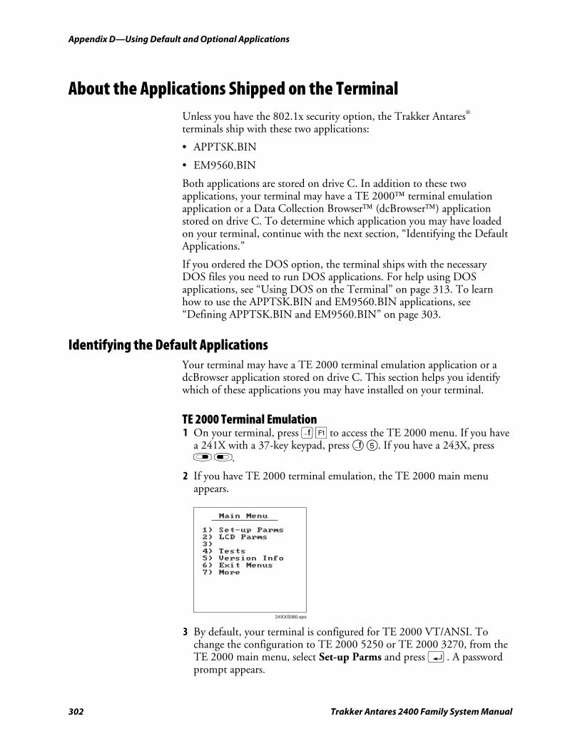
Appendix D—Using Default and Optional Applications nugget 39 AGaramond
302 Trakker Antares 2400 Family System Manual
About the Applications Shipped on the Terminal Unless you have the 802.1x security option, the Trakker Antares® terminals ship with these two applications:
• APPTSK.BIN
• EM9560.BIN
Both applications are stored on drive C. In addition to these two applications, your terminal may have a TE 2000™ terminal emulation application or a Data Collection Browser™ (dcBrowser™) application stored on drive C. To determine which application you may have loaded on your terminal, continue with the next section, “Identifying the Default Applications.”
If you ordered the DOS option, the terminal ships with the necessary DOS files you need to run DOS applications. For help using DOS applications, see “Using DOS on the Terminal” on page 313. To learn how to use the APPTSK.BIN and EM9560.BIN applications, see “Defining APPTSK.BIN and EM9560.BIN” on page 303.
Identifying the Default Applications Your terminal may have a TE 2000 terminal emulation application or a dcBrowser application stored on drive C. This section helps you identify which of these applications you may have installed on your terminal.
TE 2000 Terminal Emulation 1 On your terminal, press ( ¡ to access the TE 2000 menu. If you have
a 241X with a 37-key keypad, press ( 5. If you have a 243X, press r l.
2 If you have TE 2000 terminal emulation, the TE 2000 main menu appears.
Main Menu
1) Set-up Parms
2) LCD Parms
3)
4) Tests
5) Version Info
6) Exit Menus
7) More
24XXS080.eps
3 By default, your terminal is configured for TE 2000 VT/ANSI. To change the configuration to TE 2000 5250 or TE 2000 3270, from the TE 2000 main menu, select Set-up Parms and press ;. A password prompt appears.
nugget 39 AGaramond Appendix D—Using Default and Optional Applications
Trakker Antares 2400 Family System Manual 303
4 Type C R 5 2 4 0 1 and press ;.
5 Select Protocol Opts > Data Stream, and then select the appropriate TE 2000 configuration.
6 Save your changes by selecting Exit Menus from the TE 2000 main menu. Press Y, and type C R 5 2 4 0 1 at the Enter Password prompt.
For information about using TE 2000 IBM 3270, TE 2000 IBM 5250, or TE 2000 VT/100/220/320 and ANSI terminal emulation, see the appropriate TE 2000 guide:
• TE 2000 5250 Terminal Emulation Programmer’s Guide (P/N 977-055-004)
• TE 2000 3270 Terminal Emulation Programmer’s Guide (P/N 977-055-003)
• TE 2000 VT/ANSI Terminal Emulation Programmer’s Guide (P/N 977-055-005)
dcBrowser Client 1 On your terminal, access the TRAKKER Antares 2400 Menu System by
pressing ) ; 2 4 8 or by scanning this bar code:
TRAKKER Antares 2400 Menu System
*..-.* *..-.*
2 From the Main Menu, choose System Menu > File Manager.
3 Select drive C and then press Enter. A list of applications that are loaded on your terminal appears. If you have the dcBrowser client loaded on your terminal, this filename is listed:
DCBT24.BIN
If you do not see this filename, you do not have the dcBrowser client loaded on your terminal.
For information about using dcBrowser, see the online help that ships with your dcBrowser gateway software.
Defining APPTSK.BIN and EM9560.BIN Unless you have the 802.1x security option, you can run APPTSK.BIN or EM9560.BIN.
APPTSK.BIN This application is the default application on all terminals. If you exit an application or if certain errors occur, the terminal resets and runs
Appendix D—Using Default and Optional Applications nugget 39 AGaramond
304 Trakker Antares 2400 Family System Manual
APPTSK.BIN. You can use APPTSK.BIN to scan, enter, transmit, and display data.
EM9560.BIN This application emulates a subset of the functionality available on the Intermec 95XX terminals, such as the 9512 and 9560. You can use EM9560.BIN to scan, enter, transmit, and display data.
APPTSK.BIN and EM9560.BIN include these features:
• Works with any protocol that is supported on the terminal. Both the terminal and the device you are communicating with must use the same protocol (serial, Ethernet, or RF) and parameter settings.
• Sends scanned or keyboard data out all serial, Ethernet, or RF ports.
• Buffers the keyboard data until you press ;.
• Receives data from any serial, Ethernet, or RF port, displays the data on the terminal screen, and parses the data for commands.
• Receives data through any serial port and transmits it out the Ethernet or RF port.
• Receives data through the Ethernet or RF port and transmits it out all serial ports.
• (APPTSK.BIN only) Displays the time and date, which can be toggled on and off.
The main difference between the two applications is that you can use the EM9560.BIN application to emulate specific functions of the 95XXs.
Defining the Emulation Features of EM9560.BIN With the EM9560.BIN application, you can use the programmable terminal as a remote input/output terminal in which all prompts and commands are controlled by the host computer. With this application, the terminal is similar to a 95XX in Data Entry mode with no application running.
Note: For the 95XXs, Data Entry mode with no application running is also referred to as an unprogrammed state or 95XX dumb terminal mode.
EM9560.BIN lets you use the terminal to emulate these specific 95XX features:
• An Enter key without any preceding data transmits an empty data packet.
• The terminal display is similar to, but not identical to, the 9560 buffered display mode.
• All function keys transmit the corresponding characters F1, F2, and so on.
nugget 39 AGaramond Appendix D—Using Default and Optional Applications
Trakker Antares 2400 Family System Manual 305
• When Code 128 is configured for Standard Code 128 symbology and you scan a UCC/EAN label, the terminal will discard the Function 1 characters. Although this does not meet the industry standard for Code 128, it does emulate the 95XX, which was manufactured before the current standard was established. Other Code 128 configurations work as defined in this system manual.
• The Set Time and Date reader (data entry) command is supported. When the terminal receives a time broadcast command (/+) from the 9154 or 9161 controller, the command sets the clock on the terminal.
• The High Beep reader command is supported. When a backslash character (\) is sent to the terminal through any serial or network port, the terminal sounds a high beep.
• The Low Beep reader command is supported. When the BEL character is sent to the terminal through any serial or network port, the terminal sounds a low beep.
• When control codes (ANSI escape sequences) are sent to the terminal through any serial or network port, the terminal formats the display. For a list of control codes, see the next section, “Using Display Control Codes.”
• Buffered and transparent display modes are supported. The Display Setting configuration command (OD) is also supported. For help, see “Using Display Modes” on page 306.
• You can emulate Accumulate mode so that keypad data can be combined with scanned data. For help, see “Using Accumulate Mode” on page 307.
• Preamble A, Preamble B, and Postamble C are supported through the AA, AB, and AC configuration commands or through the reader commands +., ++, and +%. For help, see “Setting Preambles and Postambles” on page 308.
• Full ASCII mode for Code 39 can be configured through the CB or RB configuration commands or through the reader commands +$ and -$. For help, see “Full ASCII Mode for Code 39” on page 309.
• You can add message headers that indicate the length of the message. For help, see “Using Message Length Headers” on page 310.
• The Exit Configuration Mode, Save Settings configuration command ($-) is not required, but bar code labels with this command scan correctly.
Using Display Control Codes You can use control codes to position the cursor or to format the terminal display. The EM9560.BIN application recognizes the display control codes listed next.
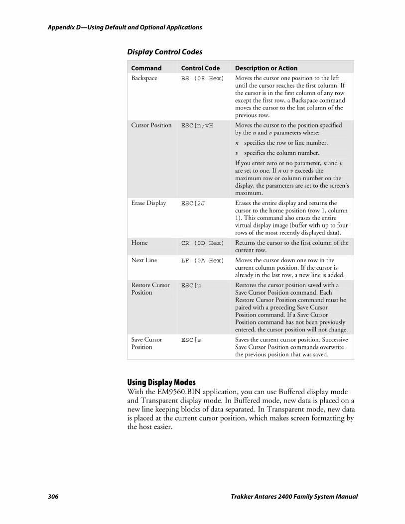
Appendix D—Using Default and Optional Applications nugget 39 AGaramond
306 Trakker Antares 2400 Family System Manual
Display Control Codes
Command Control Code Description or Action
Backspace BS (08 Hex) Moves the cursor one position to the left until the cursor reaches the first column. If the cursor is in the first column of any row except the first row, a Backspace command moves the cursor to the last column of the previous row.
Cursor Position ESC[n;vH Moves the cursor to the position specified by the n and v parameters where:
n specifies the row or line number.
v specifies the column number.
If you enter zero or no parameter, n and v are set to one. If n or v exceeds the maximum row or column number on the display, the parameters are set to the screen’s maximum.
Erase Display ESC[2J Erases the entire display and returns the cursor to the home position (row 1, column 1). This command also erases the entire virtual display image (buffer with up to four rows of the most recently displayed data).
Home CR (0D Hex) Returns the cursor to the first column of the current row.
Next Line LF (0A Hex) Moves the cursor down one row in the current column position. If the cursor is already in the last row, a new line is added.
Restore Cursor Position
ESC[u Restores the cursor position saved with a Save Cursor Position command. Each Restore Cursor Position command must be paired with a preceding Save Cursor Position command. If a Save Cursor Position command has not been previously entered, the cursor position will not change.
Save Cursor Position
ESC[s Saves the current cursor position. Successive Save Cursor Position commands overwrite the previous position that was saved.
Using Display Modes With the EM9560.BIN application, you can use Buffered display mode and Transparent display mode. In Buffered mode, new data is placed on a new line keeping blocks of data separated. In Transparent mode, new data is placed at the current cursor position, which makes screen formatting by the host easier.
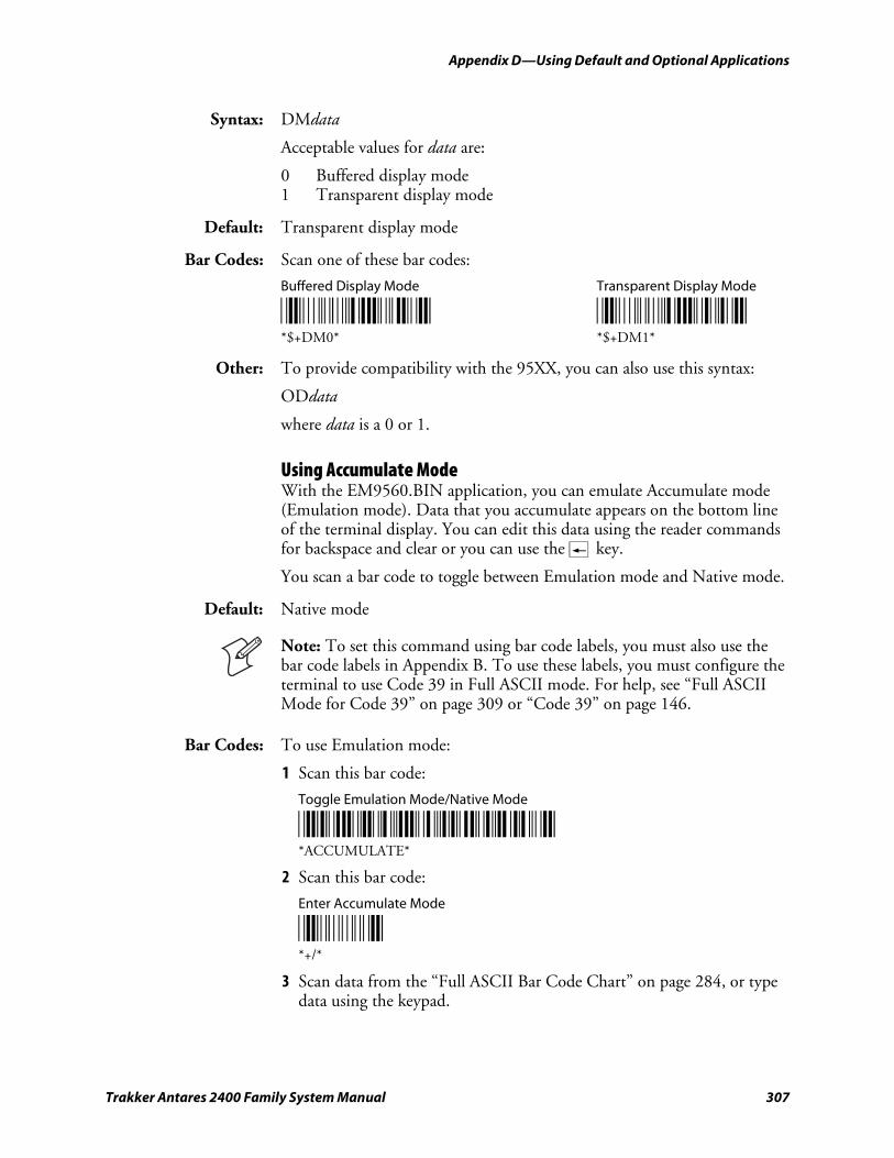
nugget 39 AGaramond Appendix D—Using Default and Optional Applications
Trakker Antares 2400 Family System Manual 307
Syntax: DMdata
Acceptable values for data are:
0 Buffered display mode 1 Transparent display mode
Default: Transparent display mode
Bar Codes: Scan one of these bar codes:
Buffered Display Mode Transparent Display Mode
*$+DM0* *$+DM1* *$+DM0* *$+DM1*
Other: To provide compatibility with the 95XX, you can also use this syntax:
ODdata
where data is a 0 or 1.
Using Accumulate Mode With the EM9560.BIN application, you can emulate Accumulate mode (Emulation mode). Data that you accumulate appears on the bottom line of the terminal display. You can edit this data using the reader commands for backspace and clear or you can use the « key.
You scan a bar code to toggle between Emulation mode and Native mode.
Default: Native mode
Note: To set this command using bar code labels, you must also use the bar code labels in Appendix B. To use these labels, you must configure the terminal to use Code 39 in Full ASCII mode. For help, see “Full ASCII Mode for Code 39” on page 309 or “Code 39” on page 146.
Bar Codes: To use Emulation mode:
1 Scan this bar code:
Toggle Emulation Mode/Native Mode
*ACCUMULATE* *ACCUMULATE*
2 Scan this bar code:
Enter Accumulate Mode
*+/* *+/*
3 Scan data from the “Full ASCII Bar Code Chart” on page 284, or type data using the keypad.
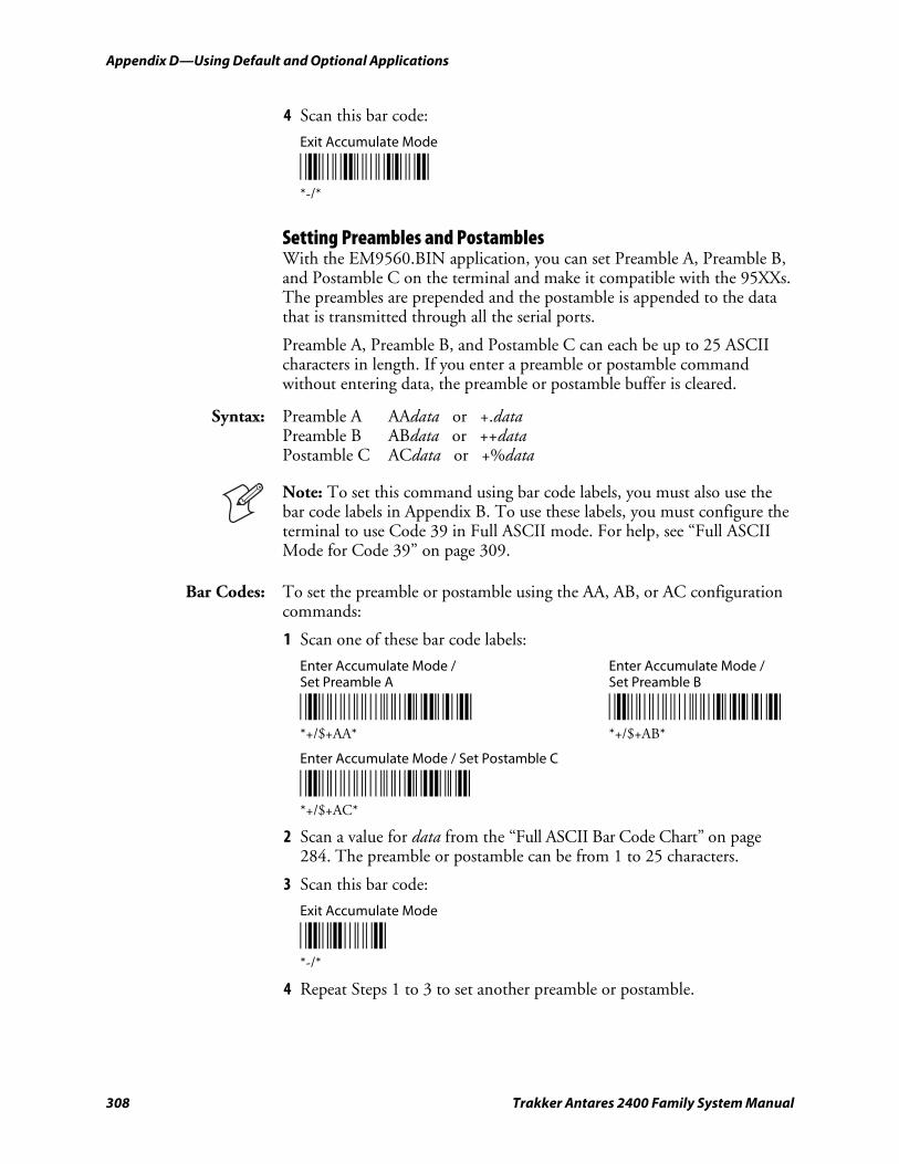
Appendix D—Using Default and Optional Applications nugget 39 AGaramond
308 Trakker Antares 2400 Family System Manual
4 Scan this bar code:
Exit Accumulate Mode
*/M/O* *-/*
Setting Preambles and Postambles With the EM9560.BIN application, you can set Preamble A, Preamble B, and Postamble C on the terminal and make it compatible with the 95XXs. The preambles are prepended and the postamble is appended to the data that is transmitted through all the serial ports.
Preamble A, Preamble B, and Postamble C can each be up to 25 ASCII characters in length. If you enter a preamble or postamble command without entering data, the preamble or postamble buffer is cleared.
Syntax: Preamble A AAdata or +.data Preamble B ABdata or ++data Postamble C ACdata or +%data
Note: To set this command using bar code labels, you must also use the bar code labels in Appendix B. To use these labels, you must configure the terminal to use Code 39 in Full ASCII mode. For help, see “Full ASCII Mode for Code 39” on page 309.
Bar Codes: To set the preamble or postamble using the AA, AB, or AC configuration commands:
1 Scan one of these bar code labels:
Enter Accumulate Mode / Enter Accumulate Mode / Set Preamble A Set Preamble B
*+/$+AA* *+/$+AB* *+/$+AA* *+/$+AB*
Enter Accumulate Mode / Set Postamble C
*+/$+AC* *+/$+AC*
2 Scan a value for data from the “Full ASCII Bar Code Chart” on page 284. The preamble or postamble can be from 1 to 25 characters.
3 Scan this bar code:
Exit Accumulate Mode
*-/* *-/*
4 Repeat Steps 1 to 3 to set another preamble or postamble.
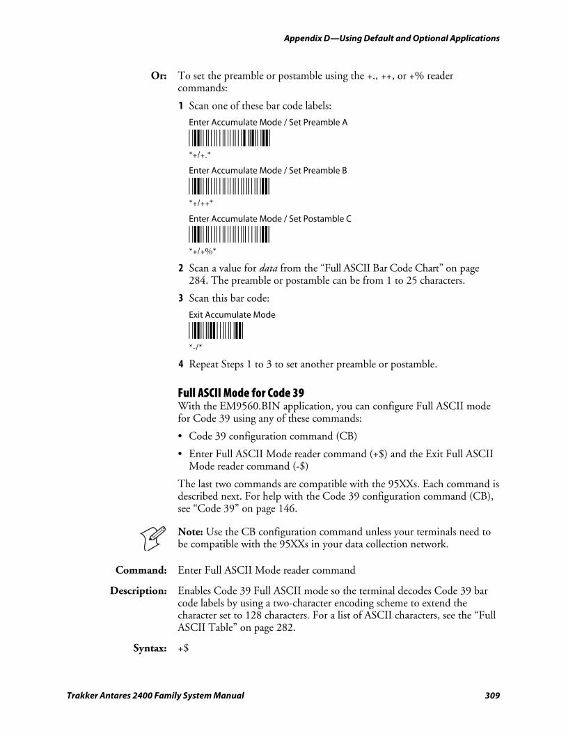
nugget 39 AGaramond Appendix D—Using Default and Optional Applications
Trakker Antares 2400 Family System Manual 309
Or: To set the preamble or postamble using the +., ++, or +% reader commands:
1 Scan one of these bar code labels:
Enter Accumulate Mode / Set Preamble A
*+/+.* *+/+.*
Enter Accumulate Mode / Set Preamble B
*+/++* *+/++*
Enter Accumulate Mode / Set Postamble C
*+/+%* *+/+%*
2 Scan a value for data from the “Full ASCII Bar Code Chart” on page 284. The preamble or postamble can be from 1 to 25 characters.
3 Scan this bar code:
Exit Accumulate Mode
*-/* *-/*
4 Repeat Steps 1 to 3 to set another preamble or postamble.
Full ASCII Mode for Code 39 With the EM9560.BIN application, you can configure Full ASCII mode for Code 39 using any of these commands:
• Code 39 configuration command (CB)
• Enter Full ASCII Mode reader command (+$) and the Exit Full ASCII Mode reader command (-$)
The last two commands are compatible with the 95XXs. Each command is described next. For help with the Code 39 configuration command (CB), see “Code 39” on page 146.
Note: Use the CB configuration command unless your terminals need to be compatible with the 95XXs in your data collection network.
Command: Enter Full ASCII Mode reader command
Description: Enables Code 39 Full ASCII mode so the terminal decodes Code 39 bar code labels by using a two-character encoding scheme to extend the character set to 128 characters. For a list of ASCII characters, see the “Full ASCII Table” on page 282.
Syntax: +$
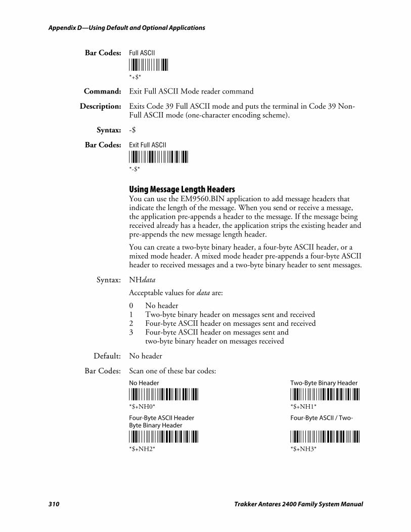
Appendix D—Using Default and Optional Applications nugget 39 AGaramond
310 Trakker Antares 2400 Family System Manual
Bar Codes: Full ASCII
*+$* *+$*
Command: Exit Full ASCII Mode reader command
Description: Exits Code 39 Full ASCII mode and puts the terminal in Code 39 Non-Full ASCII mode (one-character encoding scheme).
Syntax: -$
Bar Codes: Exit Full ASCII
*/M/D* *-$*
Using Message Length Headers You can use the EM9560.BIN application to add message headers that indicate the length of the message. When you send or receive a message, the application pre-appends a header to the message. If the message being received already has a header, the application strips the existing header and pre-appends the new message length header.
You can create a two-byte binary header, a four-byte ASCII header, or a mixed mode header. A mixed mode header pre-appends a four-byte ASCII header to received messages and a two-byte binary header to sent messages.
Syntax: NHdata
Acceptable values for data are:
0 No header 1 Two-byte binary header on messages sent and received 2 Four-byte ASCII header on messages sent and received 3 Four-byte ASCII header on messages sent and two-byte binary header on messages received
Default: No header
Bar Codes: Scan one of these bar codes:
No Header Two-Byte Binary Header
*$+NH0* *$+NH1* *$+NH0* *$+NH1*
Four-Byte ASCII Header Four-Byte ASCII / Two-Byte Binary Header
*$+NH2* *$+NH3* *$+NH2* *$+NH3*
nugget 39 AGaramond Appendix D—Using Default and Optional Applications
Trakker Antares 2400 Family System Manual 311
Unsupported 95XX Features These 95XX features are not supported by the EM9560.BIN application on the terminal.
• Capacity reader command (%$).
• Command Override reader (data entry) command (DLE).
• Download Program command from the 9154 or 9161 controller. Use the Transmit File reader command. For help, see “Transmit File” on page 116.
• Forward and Review reader commands (%+ and %/).
• Right Host Message reader command (HT).
• Computer Response Required Mode (CRRM) configuration command (PB), Enter CRRM reader command (./), and Exit CRRM reader command (.-).
• Preamble A Required configuration command (OA).
• Resume IRL configuration command (XG).
• Separate transmit and receive EOM characters (PI and PJ). The configurable EOM (PF, YZ) is used for both transmit and receive EOM.
Note: Although these 95XX features are not supported, the terminals have many additional features such as Ethernet or RF communications that are not available on the 95XXs.
Running APPTSK.BIN and EM9560.BIN There are two ways to run APPTSK.BIN or EM9560.BIN:
• Use the Run Program reader command.
• Use the TRAKKER Antares 2400 Menu System.
The instructions in this section explain how to use the Run Program reader command. For help using the TRAKKER Antares 2400 Menu System to run an application, see Chapter 3, “Developing and Using Applications.”
To run APPTSK.BIN or EM9560.BIN on the terminal
1 Scan one of these bar code labels:
Run APPTSK.BIN
*/O/OC/ZAPPTSK/NBIN* *//C:APPTSK.BIN*
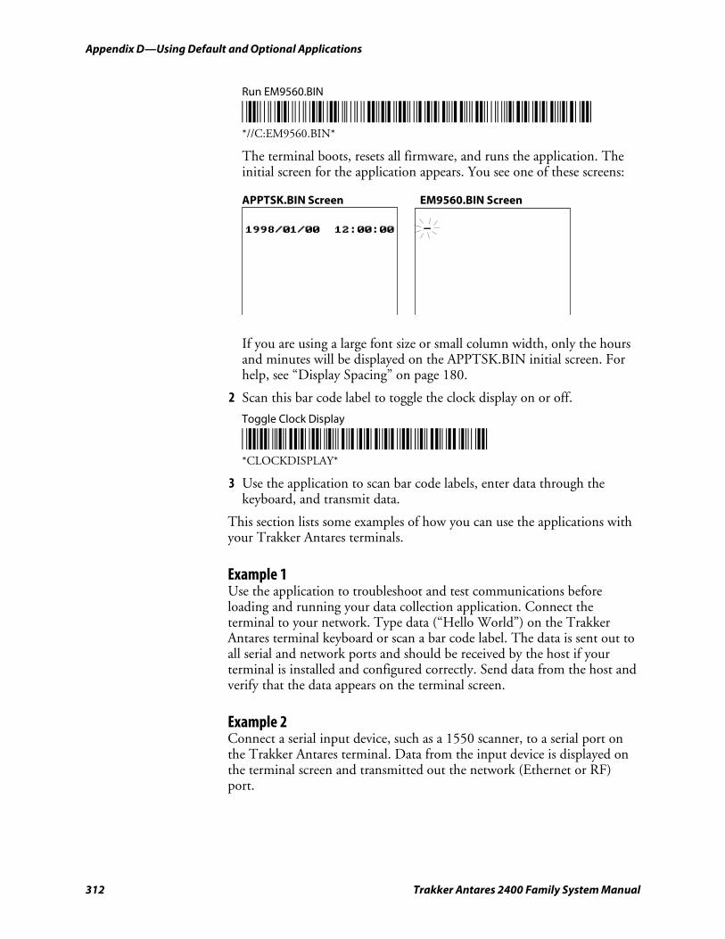
Appendix D—Using Default and Optional Applications nugget 39 AGaramond
312 Trakker Antares 2400 Family System Manual
Run EM9560.BIN
*/O/OC/ZEM9560/NBIN* *//C:EM9560.BIN*
The terminal boots, resets all firmware, and runs the application. The initial screen for the application appears. You see one of these screens:
APPTSK.BIN Screen EM9560.BIN Screen
1998/01/00 12:00:00
If you are using a large font size or small column width, only the hours and minutes will be displayed on the APPTSK.BIN initial screen. For help, see “Display Spacing” on page 180.
2 Scan this bar code label to toggle the clock display on or off.
Toggle Clock Display
*CLOCKDISPLAY* *CLOCKDISPLAY*
3 Use the application to scan bar code labels, enter data through the keyboard, and transmit data.
This section lists some examples of how you can use the applications with your Trakker Antares terminals.
Example 1 Use the application to troubleshoot and test communications before loading and running your data collection application. Connect the terminal to your network. Type data (“Hello World”) on the Trakker Antares terminal keyboard or scan a bar code label. The data is sent out to all serial and network ports and should be received by the host if your terminal is installed and configured correctly. Send data from the host and verify that the data appears on the terminal screen.
Example 2 Connect a serial input device, such as a 1550 scanner, to a serial port on the Trakker Antares terminal. Data from the input device is displayed on the terminal screen and transmitted out the network (Ethernet or RF) port.
nugget 39 AGaramond Appendix D—Using Default and Optional Applications
Trakker Antares 2400 Family System Manual 313
Example 3 Connect the TD2400 communications dock to a serial port on the 2485. Use a 2420 to collect data. Use the TD2400 communications dock to upload data from the 2420 to the 2485. Data is transmitted to the 2485 and out the Ethernet or RF port to the connected network devices.
Example 4 Use the 248X as a gateway between the CrossBar network and the Ethernet or RF network. Connect the 248X as a downline device in your CrossBar network. Connect the 2480/1 with the Ethernet option to your Ethernet network, or connect the 2485/6 to your RF network. While running the APPTSK.BIN or EM9560.BIN application, you can send data from the Ethernet or RF network through the 248X to the 9154 or 9161 and vice versa.
Example 5 Connect the COM1 serial port to the COM2 serial port on a 246X or 248X terminal. Use the terminal to configure itself by typing and entering configuration commands on the keypad or keyboard.
Example 6 Connect the serial port on the 248X to the serial port on the 246X terminal. Use the 248X to configure the 246X by typing and entering configuration commands on the 248X keypad.
Using DOS on the Terminal With the DOS option, the Trakker Antares terminals can run ROM-DOS™, which is compatible with DOS version 6.22. ROM-DOS provides application compatibility at the DOS level and interface compatibility at the BIOS level.
On each DOS drive, filenames are customer defined using eight characters with a three-character extension. You cannot define any subdirectories.
24XXS085.eps
Drive C
Drive C Drive C
DOS RAMDrive
Optional read/writeDOS drive
64K read-onlyflash DOS boot drive
Configurable DOSRAM drive
750K flash drive
DriveB
Drive A
Appendix D—Using Default and Optional Applications nugget 39 AGaramond
314 Trakker Antares 2400 Family System Manual
DOS Drives
Drive Description
Drive A This drive is a 64K block of flash memory that is a read-only DOS boot drive. You can configure drive A, but you cannot write to it within an application. Drive A is created and initialized once you run the DOS.BIN application.
Drive B This drive is an optional read/write DOS drive that resides as a subdirectory on drive C. Drive B is limited by the space available on drive C. You can configure drive B by modifying the DRIVEB.IMG file that defines the ROM-DOS commands available on the terminal. For help, see “Customizing Drive B” on page 324.
Drive C This drive is a 2MB flash drive. You can use up to 750K of this flash drive to store up to 128 files, which includes drive B. DOS .EXE applications must be stored on drive C. You use standard ANSI C library interface definitions to access the information on this drive.
The following DOS files are installed originally on drive C.
File Definition
DOS.BIN This application reboots and runs ROM-DOS on a Trakker Antares terminal so that you can run DOS .EXE applications.
ROM-DOS.IMG This file is the image file for ROM-DOS version 6.22.
DRIVEB.IMG This image file contains the contents of DOS drive B. You cannot reference drive B from a Trakker Antares .BIN application file. If you delete this file, you lose drive B and the ROM-DOS commands that are defined for drive B.
Note: If you do not want to use DOS on the Trakker Antares terminal, you can save space by deleting DOS.BIN, ROM-DOS.IMG, and DRIVEB.IMG from drive C.
DOS RAM Drive This drive is a configurable DOS RAM drive. The contents of this drive are erased when you boot or reset the terminal. You use standard ANSI C functions to access the files on this drive. If you configure a DOS RAM drive, DOS assigns drive C to the RAM drive and reassigns the remaining Trakker Antares drives. For example, the Trakker Antares drive C becomes drive D. For help creating a DOS RAM drive, see “Configuring a DOS RAM Drive” on page 325. By default, the RAM drive is not configured and the memory is available for programmable (Malloc) memory.
There are two types of RAM drives that are mutually exclusive depending on whether you run native Trakker Antares .BIN applications or DOS .EXE applications. You use the standard RAM drive E for .BIN applications or you use a DOS RAM drive for DOS .EXE applications. Before you start using DOS on the terminal, you must disable the standard RAM drive. For help, see “RAM Drive Size” on page 223.
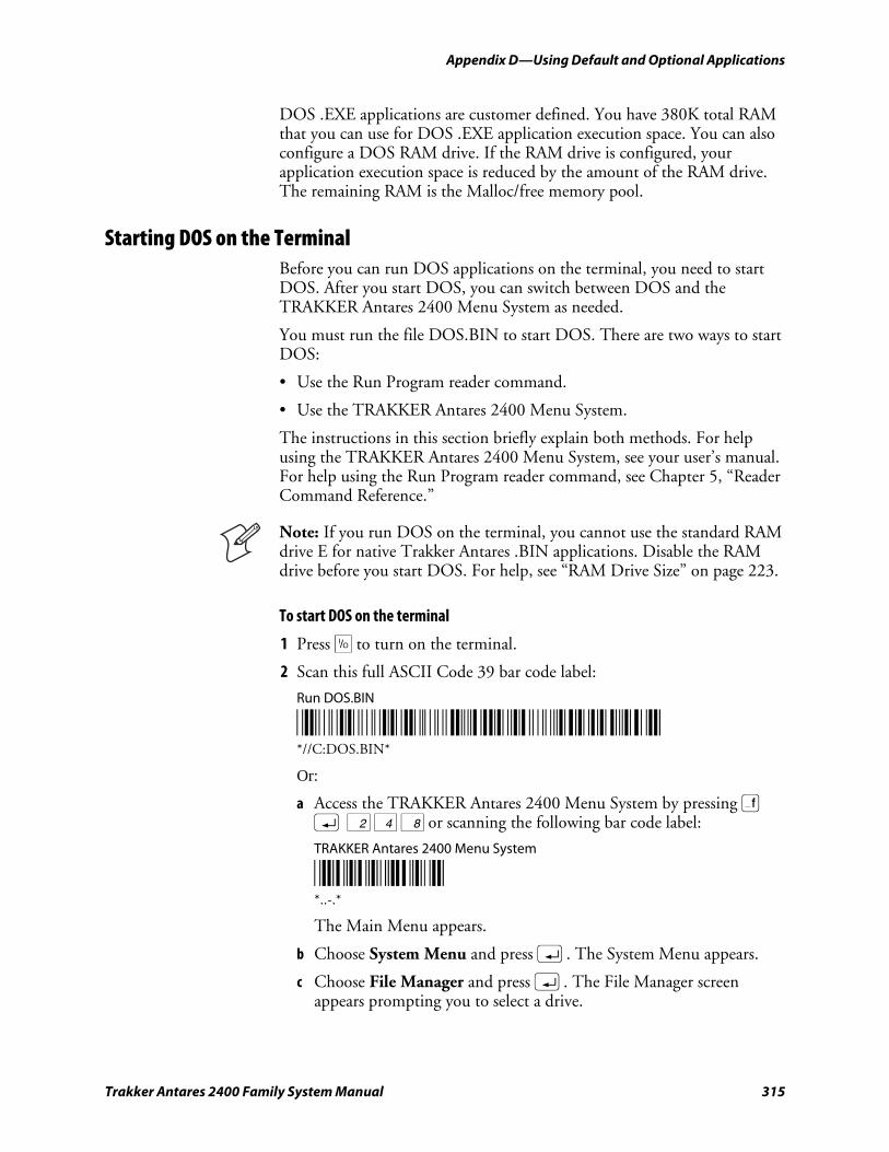
nugget 39 AGaramond Appendix D—Using Default and Optional Applications
Trakker Antares 2400 Family System Manual 315
DOS .EXE applications are customer defined. You have 380K total RAM that you can use for DOS .EXE application execution space. You can also configure a DOS RAM drive. If the RAM drive is configured, your application execution space is reduced by the amount of the RAM drive. The remaining RAM is the Malloc/free memory pool.
Starting DOS on the Terminal Before you can run DOS applications on the terminal, you need to start DOS. After you start DOS, you can switch between DOS and the TRAKKER Antares 2400 Menu System as needed.
You must run the file DOS.BIN to start DOS. There are two ways to start DOS:
• Use the Run Program reader command.
• Use the TRAKKER Antares 2400 Menu System.
The instructions in this section briefly explain both methods. For help using the TRAKKER Antares 2400 Menu System, see your user’s manual. For help using the Run Program reader command, see Chapter 5, “Reader Command Reference.”
Note: If you run DOS on the terminal, you cannot use the standard RAM drive E for native Trakker Antares .BIN applications. Disable the RAM drive before you start DOS. For help, see “RAM Drive Size” on page 223.
To start DOS on the terminal
1 Press œ to turn on the terminal.
2 Scan this full ASCII Code 39 bar code label:
Run DOS.BIN
*/O/OC/ZDOS/NBIN* *//C:DOS.BIN*
Or:
a Access the TRAKKER Antares 2400 Menu System by pressing ) ; 2 4 8 or scanning the following bar code label:
TRAKKER Antares 2400 Menu System
*..-.* *..-.*
The Main Menu appears.
b Choose System Menu and press ;. The System Menu appears.
c Choose File Manager and press ;. The File Manager screen appears prompting you to select a drive.
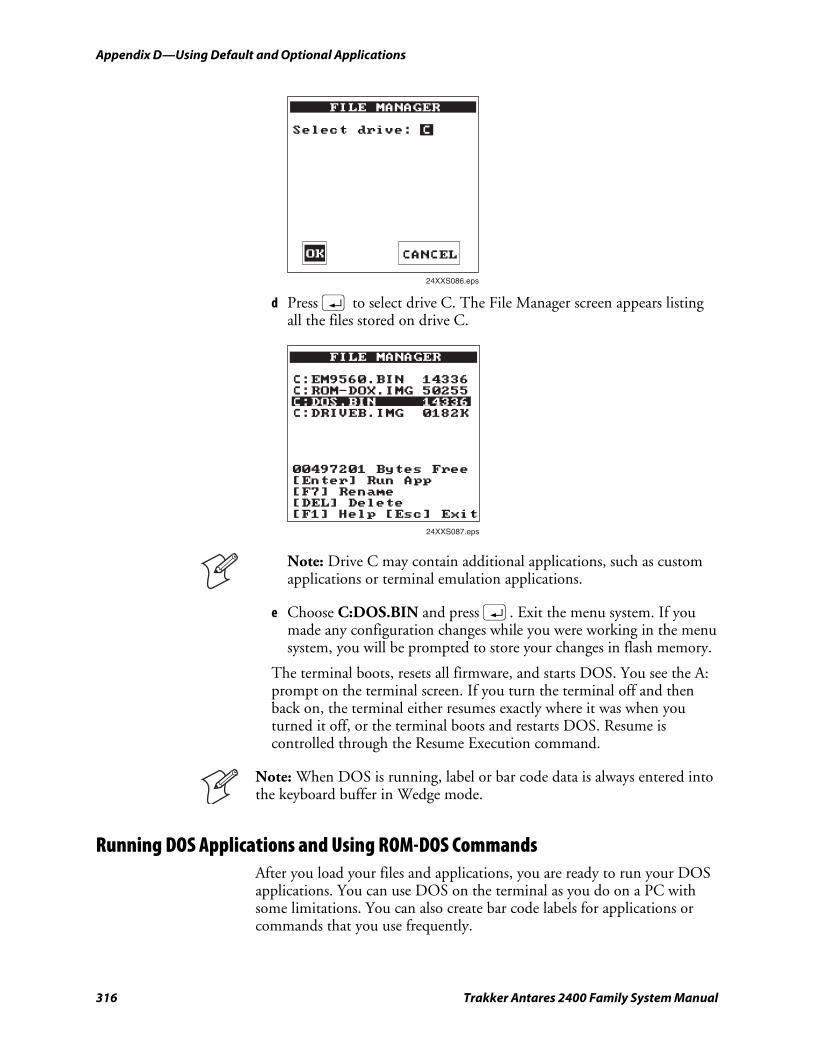
Appendix D—Using Default and Optional Applications nugget 39 AGaramond
316 Trakker Antares 2400 Family System Manual
FILE MANAGER
Select drive: C
24XXS086.eps
OK CANCEL
d Press ; to select drive C. The File Manager screen appears listing all the files stored on drive C.
FILE MANAGER
C:EM9560.BIN 14336C:ROM-DOX.IMG 50255C:DOS.BIN 14336C:DRIVEB.IMG 0182K
00497201 Bytes Free[Enter] Run App[F7] Rename[DEL] Delete[F1] Help [Esc] Exit
24XXS087.eps
Note: Drive C may contain additional applications, such as custom applications or terminal emulation applications.
e Choose C:DOS.BIN and press ;. Exit the menu system. If you made any configuration changes while you were working in the menu system, you will be prompted to store your changes in flash memory.
The terminal boots, resets all firmware, and starts DOS. You see the A: prompt on the terminal screen. If you turn the terminal off and then back on, the terminal either resumes exactly where it was when you turned it off, or the terminal boots and restarts DOS. Resume is controlled through the Resume Execution command.
Note: When DOS is running, label or bar code data is always entered into the keyboard buffer in Wedge mode.
Running DOS Applications and Using ROM-DOS Commands After you load your files and applications, you are ready to run your DOS applications. You can use DOS on the terminal as you do on a PC with some limitations. You can also create bar code labels for applications or commands that you use frequently.
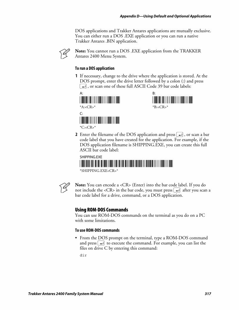
nugget 39 AGaramond Appendix D—Using Default and Optional Applications
Trakker Antares 2400 Family System Manual 317
DOS applications and Trakker Antares applications are mutually exclusive. You can either run a DOS .EXE application or you can run a native Trakker Antares .BIN application.
Note: You cannot run a DOS .EXE application from the TRAKKER Antares 2400 Menu System.
To run a DOS application
1 If necessary, change to the drive where the application is stored. At the DOS prompt, enter the drive letter followed by a colon (:) and press ;, or scan one of these full ASCII Code 39 bar code labels:
A: B:
*A/Z$M* *B/Z$M* *A:<CR>* *B:<CR>*
C:
*C/Z$M* *C:<CR>*
2 Enter the filename of the DOS application and press ;, or scan a bar code label that you have created for the application. For example, if the DOS application filename is SHIPPING.EXE, you can create this full ASCII bar code label:
SHIPPING.EXE
*SHIPPING.EXE$M* *SHIPPING.EXE<CR>*
Note: You can encode a <CR> (Enter) into the bar code label. If you do not include the <CR> in the bar code, you must press ; after you scan a bar code label for a drive, command, or a DOS application.
Using ROM-DOS Commands You can use ROM-DOS commands on the terminal as you do on a PC with some limitations.
To use ROM-DOS commands
• From the DOS prompt on the terminal, type a ROM-DOS command and press ; to execute the command. For example, you can list the files on drive C by entering this command:
dir
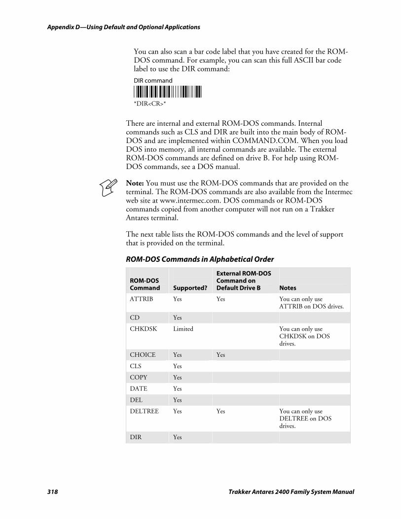
Appendix D—Using Default and Optional Applications nugget 39 AGaramond
318 Trakker Antares 2400 Family System Manual
You can also scan a bar code label that you have created for the ROM-DOS command. For example, you can scan this full ASCII bar code label to use the DIR command:
DIR command
*DIR$M* *DIR<CR>*
There are internal and external ROM-DOS commands. Internal commands such as CLS and DIR are built into the main body of ROM-DOS and are implemented within COMMAND.COM. When you load DOS into memory, all internal commands are available. The external ROM-DOS commands are defined on drive B. For help using ROM-DOS commands, see a DOS manual.
Note: You must use the ROM-DOS commands that are provided on the terminal. The ROM-DOS commands are also available from the Intermec web site at www.intermec.com. DOS commands or ROM-DOS commands copied from another computer will not run on a Trakker Antares terminal.
The next table lists the ROM-DOS commands and the level of support that is provided on the terminal.
ROM-DOS Commands in Alphabetical Order
ROM-DOS Command
Supported?
External ROM-DOS Command on Default Drive B
Notes
ATTRIB Yes Yes You can only use ATTRIB on DOS drives.
CD Yes
CHKDSK Limited You can only use CHKDSK on DOS drives.
CHOICE Yes Yes
CLS Yes
COPY Yes
DATE Yes
DEL Yes
DELTREE Yes Yes You can only use DELTREE on DOS drives.
DIR Yes
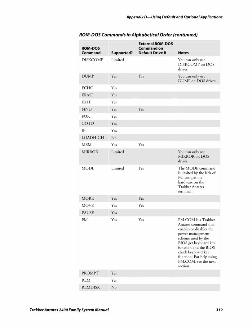
nugget 39 AGaramond Appendix D—Using Default and Optional Applications
Trakker Antares 2400 Family System Manual 319
ROM-DOS Commands in Alphabetical Order (continued)
ROM-DOS Command
Supported?
External ROM-DOS Command on Default Drive B
Notes
DISKCOMP Limited You can only use DISKCOMP on DOS drives.
DUMP Yes Yes You can only use DUMP on DOS drives.
ECHO Yes
ERASE Yes
EXIT Yes
FIND Yes Yes
FOR Yes
GOTO Yes
IF Yes
LOADHIGH No
MEM Yes Yes
MIRROR Limited You can only use MIRROR on DOS drives.
MODE Limited Yes The MODE command is limited by the lack of PC-compatible hardware on the Trakker Antares terminal.
MORE Yes Yes
MOVE Yes Yes
PAUSE Yes
PM Yes Yes PM.COM is a Trakker Antares command that enables or disables the power management scheme used by the BIOS get keyboard key function and the BIOS check keyboard key function. For help using PM.COM, see the next section.
PROMPT Yes
REM Yes
REMDISK No
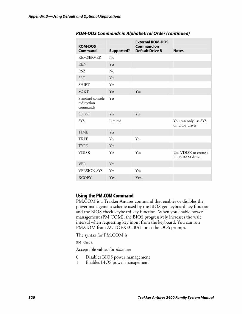
Appendix D—Using Default and Optional Applications nugget 39 AGaramond
320 Trakker Antares 2400 Family System Manual
ROM-DOS Commands in Alphabetical Order (continued)
ROM-DOS Command
Supported?
External ROM-DOS Command on Default Drive B
Notes
REMSERVER No
REN Yes
RSZ No
SET Yes
SHIFT Yes
SORT Yes Yes
Standard console redirection commands
Yes
SUBST Yes Yes
SYS Limited You can only use SYS on DOS drives.
TIME Yes
TREE Yes Yes
TYPE Yes
VDISK Yes Yes Use VDISK to create a DOS RAM drive.
VER Yes
VERSION.SYS Yes Yes
XCOPY Yes Yes
Using the PM.COM Command PM.COM is a Trakker Antares command that enables or disables the power management scheme used by the BIOS get keyboard key function and the BIOS check keyboard key function. When you enable power management (PM.COM), the BIOS progressively increases the wait interval when requesting key input from the keyboard. You can run PM.COM from AUTOEXEC.BAT or at the DOS prompt.
The syntax for PM.COM is:
PM data
Acceptable values for data are:
0 Disables BIOS power management 1 Enables BIOS power management
nugget 39 AGaramond Appendix D—Using Default and Optional Applications
Trakker Antares 2400 Family System Manual 321
Stopping DOS and Running a .BIN Application You can stop or exit DOS by running a native Trakker Antares .BIN application. Once you run a .BIN application other than DOS.BIN, the terminal stops or exits DOS. There are two ways to run an application:
• Use the Run Program reader command. For help, see “Run Program” on page 112.
• Use the TRAKKER Antares 2400 Menu System. For help, see the configuration chapter in your user’s manual.
Customizing DOS Drives and Commands You can customize DOS on your Trakker Antares terminal by:
• changing AUTOEXEC.BAT or CONFIG.SYS and customizing drive A.
• adding or removing external ROM-DOS commands that are available on drive B.
• creating a DOS application or TSR for drive C.
Intermec recommends that you create all the files on your PC, and then download the files to your terminal. The next section explains the DOS software tools that you need to customize drive A and B.
Trakker Antares DOS Software Tools The DOS software tools listed in the following table are necessary for creating and downloading files to drives A and B.
DOS Software Tools
Software Tool Definition
MAKE_A.BAT Creates a file named DRIVEA.BIN that contains the drive A image. The maximum size of drive A is 64K.
MAKE_B.BAT Creates a DRIVEB.IMG file that contains the external ROM-DOS commands for drive B. You can copy the DRIVEB.IMG file from the PC to drive C on the terminal.
PUT_A.BAT Downloads the drive A image file (DRIVEA.BIN) from a PC to the terminal. This tool actually replaces all files on drive A.
The DOS software tools, ROM-DOS commands for drive B, and drive A files are available from the Intermec web site at www.intermec.com. (Choose Support, Product Support, and then Downloads.) For additional help, contact your local Intermec service representative.
Note: The self-extracting executable file that you download from the Intermec web site includes the DOS software tools and support files; ROM-DOS commands; and drive A files. LISTFILE.DRV,
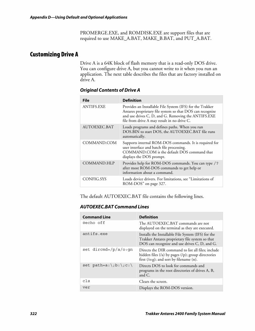
Appendix D—Using Default and Optional Applications nugget 39 AGaramond
322 Trakker Antares 2400 Family System Manual
PROMERGE.EXE, and ROMDISK.EXE are support files that are required to use MAKE_A.BAT, MAKE_B.BAT, and PUT_A.BAT.
Customizing Drive A Drive A is a 64K block of flash memory that is a read-only DOS drive. You can configure drive A, but you cannot write to it when you run an application. The next table describes the files that are factory installed on drive A.
Original Contents of Drive A
File Definition
ANTIFS.EXE Provides an Installable File System (IFS) for the Trakker Antares proprietary file system so that DOS can recognize and use drives C, D, and G. Removing the ANTIFS.EXE file from drive A may result in no drive C.
AUTOEXEC.BAT Loads programs and defines paths. When you run DOS.BIN to start DOS, the AUTOEXEC.BAT file runs automatically.
COMMAND.COM Supports internal ROM-DOS commands. It is required for user interface and batch file processing. COMMAND.COM is the default DOS command that displays the DOS prompt.
COMMAND.HLP Provides help for ROM-DOS commands. You can type /? after most ROM-DOS commands to get help or information about a command.
CONFIG.SYS Loads device drivers. For limitations, see “Limitations of ROM-DOS” on page 327.
The default AUTOEXEC.BAT file contains the following lines.
AUTOEXEC.BAT Command Lines
Command Line Definition @echo off The AUTOEXEC.BAT commands are not
displayed on the terminal as they are executed. antifs.exe Installs the Installable File System (IFS) for the
Trakker Antares proprietary file system so that DOS can recognize and use drives C, D, and G.
set dircmd=/p/a/o:gn Directs the DIR command to list all files; include hidden files (/a) by pages (/p); group directories first (/o:g); and sort by filename (n).
set path=a:\;b:\;c:\ Directs DOS to look for commands and programs in the root directories of drives A, B, and C.
cls Clears the screen. ver Displays the ROM-DOS version.
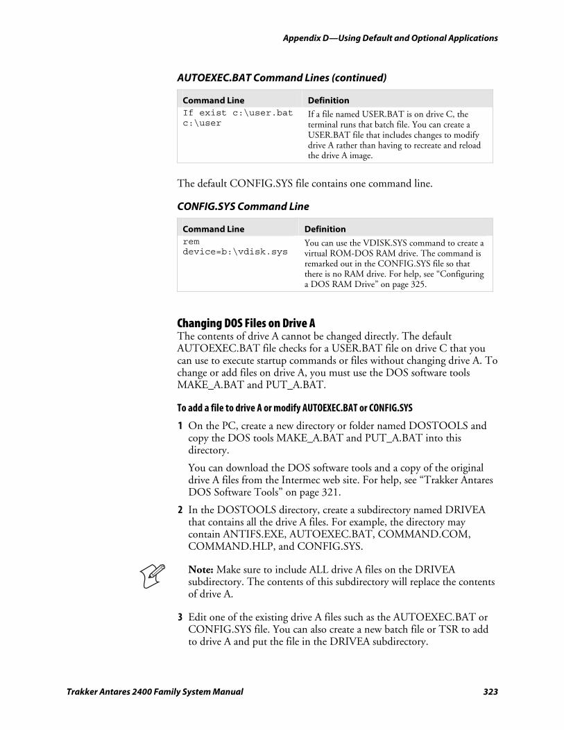
nugget 39 AGaramond Appendix D—Using Default and Optional Applications
Trakker Antares 2400 Family System Manual 323
AUTOEXEC.BAT Command Lines (continued)
Command Line Definition If exist c:\user.bat c:\user
If a file named USER.BAT is on drive C, the terminal runs that batch file. You can create a USER.BAT file that includes changes to modify drive A rather than having to recreate and reload the drive A image.
The default CONFIG.SYS file contains one command line.
CONFIG.SYS Command Line
Command Line Definition rem device=b:\vdisk.sys
You can use the VDISK.SYS command to create a virtual ROM-DOS RAM drive. The command is remarked out in the CONFIG.SYS file so that there is no RAM drive. For help, see “Configuring a DOS RAM Drive” on page 325.
Changing DOS Files on Drive A The contents of drive A cannot be changed directly. The default AUTOEXEC.BAT file checks for a USER.BAT file on drive C that you can use to execute startup commands or files without changing drive A. To change or add files on drive A, you must use the DOS software tools MAKE_A.BAT and PUT_A.BAT.
To add a file to drive A or modify AUTOEXEC.BAT or CONFIG.SYS
1 On the PC, create a new directory or folder named DOSTOOLS and copy the DOS tools MAKE_A.BAT and PUT_A.BAT into this directory.
You can download the DOS software tools and a copy of the original drive A files from the Intermec web site. For help, see “Trakker Antares DOS Software Tools” on page 321.
2 In the DOSTOOLS directory, create a subdirectory named DRIVEA that contains all the drive A files. For example, the directory may contain ANTIFS.EXE, AUTOEXEC.BAT, COMMAND.COM, COMMAND.HLP, and CONFIG.SYS.
Note: Make sure to include ALL drive A files on the DRIVEA subdirectory. The contents of this subdirectory will replace the contents of drive A.
3 Edit one of the existing drive A files such as the AUTOEXEC.BAT or CONFIG.SYS file. You can also create a new batch file or TSR to add to drive A and put the file in the DRIVEA subdirectory.
Appendix D—Using Default and Optional Applications nugget 39 AGaramond
324 Trakker Antares 2400 Family System Manual
4 From the DOSTOOLS directory, type this command:
MAKE_A.BAT
The batch file creates the image file named DRIVEA.BIN that contains all the files in the subdirectory DRIVEA.
5 Connect the PC to the terminal through a serial connection.
6 On the terminal, press ) ; 2 4 8 to access the TRAKKER Antares 2400 Menu System. The Main Menu appears.
7 Choose System Menu > Upgrade Firmware, and choose OK to continue. The next screen appears prompting you to continue upgrading the firmware. In this case, you are not actually upgrading all the firmware. You will only be replacing the files on drive A.
8 Choose Yes to continue and upgrade drive A. The terminal reboots and displays the Loader Waiting screen.
9 On your PC, open an MS-DOS window and change to the DOSTOOLS directory.
10 On your PC, type this command:
PUT_A.BAT
The Loader screen appears and the DRIVEA.IMG file is transferred to the terminal and used to replace the contents of drive A. Once the batch file is complete and drive A is replaced, the terminal boots and displays the DOS prompt.
Note: When you use PUT_A.BAT, you are replacing all files on drive A.
Customizing Drive B Drive B is an optional read/write DOS drive. It contains an image of the external ROM-DOS commands that are available by default on the Trakker Antares terminal. Drive B resides as a subdirectory on drive C and is limited by the space available on drive C.
As with drive A, the contents of drive B cannot be changed directly. To make configuration changes, you must use the DOS software tool MAKE_B.BAT.
To change drive B, you must recreate the file DRIVEB.IMG. When you do, you are replacing all files on drive B.
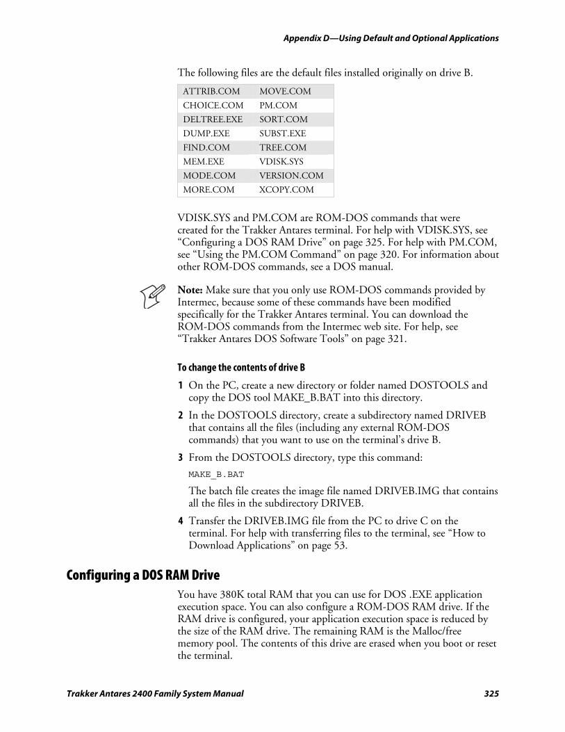
nugget 39 AGaramond Appendix D—Using Default and Optional Applications
Trakker Antares 2400 Family System Manual 325
The following files are the default files installed originally on drive B.
ATTRIB.COM MOVE.COM
CHOICE.COM PM.COM
DELTREE.EXE SORT.COM
DUMP.EXE SUBST.EXE
FIND.COM TREE.COM
MEM.EXE VDISK.SYS
MODE.COM VERSION.COM
MORE.COM XCOPY.COM
VDISK.SYS and PM.COM are ROM-DOS commands that were created for the Trakker Antares terminal. For help with VDISK.SYS, see “Configuring a DOS RAM Drive” on page 325. For help with PM.COM, see “Using the PM.COM Command” on page 320. For information about other ROM-DOS commands, see a DOS manual.
Note: Make sure that you only use ROM-DOS commands provided by Intermec, because some of these commands have been modified specifically for the Trakker Antares terminal. You can download the ROM-DOS commands from the Intermec web site. For help, see “Trakker Antares DOS Software Tools” on page 321.
To change the contents of drive B
1 On the PC, create a new directory or folder named DOSTOOLS and copy the DOS tool MAKE_B.BAT into this directory.
2 In the DOSTOOLS directory, create a subdirectory named DRIVEB that contains all the files (including any external ROM-DOS commands) that you want to use on the terminal’s drive B.
3 From the DOSTOOLS directory, type this command:
MAKE_B.BAT
The batch file creates the image file named DRIVEB.IMG that contains all the files in the subdirectory DRIVEB.
4 Transfer the DRIVEB.IMG file from the PC to drive C on the terminal. For help with transferring files to the terminal, see “How to Download Applications” on page 53.
Configuring a DOS RAM Drive You have 380K total RAM that you can use for DOS .EXE application execution space. You can also configure a ROM-DOS RAM drive. If the RAM drive is configured, your application execution space is reduced by the size of the RAM drive. The remaining RAM is the Malloc/free memory pool. The contents of this drive are erased when you boot or reset the terminal.
Appendix D—Using Default and Optional Applications nugget 39 AGaramond
326 Trakker Antares 2400 Family System Manual
To configure a DOS RAM drive
1 On your PC, edit or create the CONFIG.SYS file.
2 Remove “rem” from the start of this line:
rem device=b:\vdisk.sys
3 Add or set parameters for the DOS RAM drive using this syntax:
device=vdisk [size [secs[dirs]]][/E]
where:
vdisk VDISK is a device driver that partitions some of DOS memory as a RAM disk. Any data that is stored on the DOS RAM drive is lost when you reboot the Trakker Antares terminal. All data on the RAM drive is saved when you turn the terminal off and on (suspend and resume). The VDISK driver increases the resident size of DOS.
size Sets the size in bytes of the DOS RAM drive. The default size is 64K. The memory or size that you set is allocated from the DOS memory pool, and it will decrease the amount of memory available for applications.
secs Sets the sector size in bytes. The default value is 512 bytes per sector. You can set the sector size to 128, 256, 512, or 1024. All other values are not valid and the sector size defaults to 512.
dirs Sets the number of root directory entries. The default value is 64 directory entries. You can set the root directory entries to any number from 2 to 1024. If you enter an odd number, it is rounded up to the nearest multiple of 16 to fill the entire sector.
/E This parameter is not valid, because the Trakker Antares terminal does not contain extended memory.
4 Copy the CONFIG.SYS file to the directory or folder that contains your DOS files for drive A.
5 Create a drive A image file to download to the terminal. For help, see “Customizing Drive A” on page 322.
After you replace drive A and create the DOS RAM drive, DOS assigns drive C to the RAM drive and reassigns the remaining Trakker Antares drive letters. For example, the Trakker Antares drive C becomes drive D.
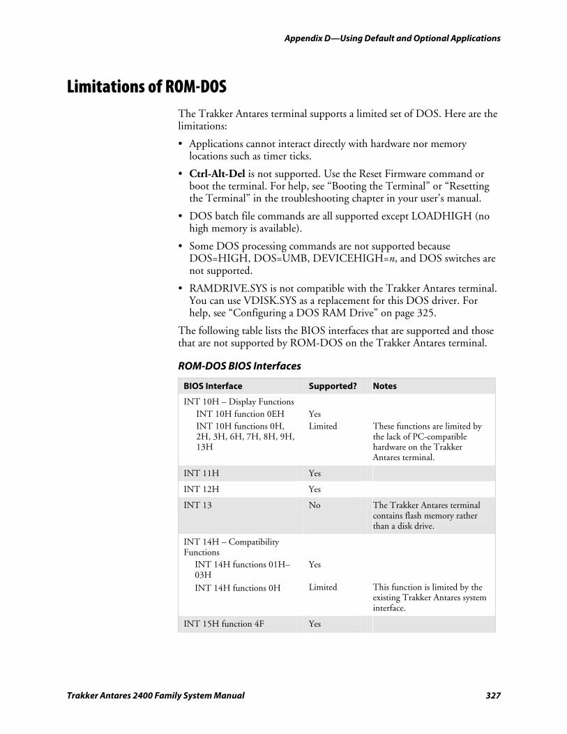
nugget 39 AGaramond Appendix D—Using Default and Optional Applications
Trakker Antares 2400 Family System Manual 327
Limitations of ROM-DOS The Trakker Antares terminal supports a limited set of DOS. Here are the limitations:
• Applications cannot interact directly with hardware nor memory locations such as timer ticks.
• Ctrl-Alt-Del is not supported. Use the Reset Firmware command or boot the terminal. For help, see “Booting the Terminal” or “Resetting the Terminal” in the troubleshooting chapter in your user’s manual.
• DOS batch file commands are all supported except LOADHIGH (no high memory is available).
• Some DOS processing commands are not supported because DOS=HIGH, DOS=UMB, DEVICEHIGH=n, and DOS switches are not supported.
• RAMDRIVE.SYS is not compatible with the Trakker Antares terminal. You can use VDISK.SYS as a replacement for this DOS driver. For help, see “Configuring a DOS RAM Drive” on page 325.
The following table lists the BIOS interfaces that are supported and those that are not supported by ROM-DOS on the Trakker Antares terminal.
ROM-DOS BIOS Interfaces
BIOS Interface Supported? Notes
INT 10H – Display Functions INT 10H function 0EH Yes INT 10H functions 0H,
2H, 3H, 6H, 7H, 8H, 9H, 13H
Limited These functions are limited by the lack of PC-compatible hardware on the Trakker Antares terminal.
INT 11H Yes
INT 12H Yes
INT 13 No The Trakker Antares terminal contains flash memory rather than a disk drive.
INT 14H – Compatibility Functions
INT 14H functions 01H–03H
Yes
INT 14H functions 0H Limited This function is limited by the existing Trakker Antares system interface.
INT 15H function 4F Yes
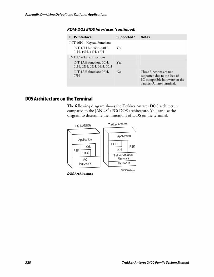
Appendix D—Using Default and Optional Applications nugget 39 AGaramond
328 Trakker Antares 2400 Family System Manual
ROM-DOS BIOS Interfaces (continued)
BIOS Interface Supported? Notes
INT 16H – Keypad Functions
INT 16H functions 00H, 01H, 10H, 11H, 12H
Yes
INT 17 – Time Functions
INT 1AH functions 00H, 01H, 02H, 03H, 04H, 05H
Yes
INT 1AH functions 06H, 07H
No These functions are not supported due to the lack of PC-compatible hardware on the Trakker Antares terminal.
DOS Architecture on the Terminal The following diagram shows the Trakker Antares DOS architecture compared to the JANUS® (PC) DOS architecture. You can use the diagram to determine the limitations of DOS on the terminal.
Application
PC (JANUS) Trakker Antares
DOS
BIOSPSK
PCHardware
Application
DOS
BIOSPSK
Trakker Antares Firmware
Hardware
24XXS088.eps DOS Architecture

Trakker Antares 2400 Family System Manual 329
Index
I
Index
330 Trakker Antares 2400 Family System Manual
Symbols and Numbers œ key
configuring, 226 enabling or disabling, 245
2400 Family described, 2 See also terminal.
8.01, firmware, overview of features, 6 802.11b network communications
AP Density, configuring, 133 configuration commands, list of, 275 Maximum Sleep Duration, configuring, 203 Medium Reservation, configuring, 204 Network Name, configuring, 212 Power Management, configuring, 220 Receive All Multicast, configuring, 224 Reservation Threshold, configuring, 225 Station Name, configuring, 242 Transmit Rate Fallback, configuring, 261 Transmit Rate, configuring, 260 WEP Encryption, configuring, 266 WEP Keys, configuring, 267 WEP Transmit Key, configuring, 269 See also RF communications.
802.1x security configuration commands
Password, 215 Server Certificate Common Name, 239 User Name, 265
error numbers and messages, 93 See also your terminal user’s manual.
8-bit binary files receiving and converting, 107 transmitting and converting, 118
95XX terminal IRL programs, converting, 51 Set Time and Date reader command, 114
A ABC Codabar, 143 Abort Program reader command, 99 Access Point screen, defined, 72 Accumulate mode, using reader commands, 97 Acknowledgement Delay Lower Limit command, 131 Acknowledgement Delay Upper Limit command, 132 active configuration, 13 address
controller IP, configuring, 166 default router, configuring, 169 DHCP (Controller), using, 173 DHCP (Terminal), using, 174 host IP, configuring, 192 Multi-Drop, configuring, 209 terminal IP, configuring, 252
AFF command, 190 Affirmative Acknowledge, See Handshake command Agent, Wavelink Avalanche component, described, 38
AIAG check digit, Code 39, 148, 151 American Blood Commission, See ABC Codabar AP Density command, 133 AP MAC Address command, 134 Append Time command, 134 Application Efficiency screen, defined, 72 Application Events screen, defined, 73 Application Simulator, defined, 49 applications
APPTSK.BIN, default application, 303 CLIENT.CPP, sample utility, 26 to 28 clone application, configuring the terminal, 23 converting
binary files, 51 IRL programs, 51 JANUS and Trakker Antares, 50
developing, 48 DOS utility, upgrading the terminal, 33, 36 DOS, described, 313 downloading
DCS 300, sending from, 62 host in a TCP/IP network, using, 24
EM9560.BIN, default application, 303 exiting, using reader commands, 99 EZBuilder, developing with, 49 LOADER.EXE, transferring files, 58, 60 Malloc diagnostic screen, defined, 82 overview, downloading and running, 53 PSK, developing with, 49 restarting, 111 running, 65, 112, 316, 321
APPTSK.BIN, 311 EM9560.BIN, 311
terminal emulation, choosing the TE 2000 configuration, 302
APPTSK.BIN application defined, 303 running, 311
ARP, defined, 9 ASCII
bar code chart, 284 to 88 characters, entering in commands, 129 control characters, list of, 284 full ASCII table, 282 full, Code 39, 147 mixed-full, Code 39, 147 non-full, Code 39, 146
Asian fonts, loading, 36 audio signals
keypad clicks, enabling or disabling, 197 testing, 76 volume, adjusting, 138, 139, 141
AUTOEXEC.BAT file, modifying, 323 Automatic mode, configuring the scanner, 228 Automatic Shutoff command, 135 automatically turning the terminal off, 135 Avalanche, Wavelink, described, 38
Index
Trakker Antares 2400 Family System Manual 331
B Backlight On and Off reader command, 100 backlight, configuring the timeout, 175 Backspace reader command, 100 bar code labels
ASCII chart, 284 to 88 decode security, configuring, 168 Multiple-Read labels, 104 regular labels, 104 scanning
accumulating data, 97 configuring the terminal, 13
using to configure the terminal, 124 using to execute reader commands, 96
bar code symbologies Codabar, configuring, 143 Code 11, configuring, 144 Code 128, configuring, 150 Code 2 of 5, configuring, 145 Code 39, configuring, 146 Code 93, configuring, 149 configuration commands, list of, 125, 272 Interleaved 2 of 5, configuring, 195 ISBT Code 128, configuring, 152 MSI, configuring, 208 PDF417, configuring, 216 Plessey, configuring, 217 UCC/EAN Code 128, configuring, 151 UPC/EAN, configuring, 261
batch file transfer, using, 107 battery, checking status, 73 Baud Rate command, 136 Beep Duration command, 138 Beep Frequency command, 139 Beep Volume command, 141 beep, testing, 76 Beeper Test screen, defined, 76 BFSK, defined, 259 binary files, converting, 51 binary protocol, configuring, 237 Boot Terminal reader command, 100 booting the terminal
configuring the œ key, 226 creating a custom logo, 52 warm boot, 111
C capitalizing characters, Keypad Caps Lock command,
using, 196 Change Configuration reader command, using, 101 changing configuration, configuration commands, 128 Character mode, EOM, described, 184 Character Set command, 141 characters, table of, 290 to 97, 298 to 300 Clear reader command, 101 Clear Task Profiles screen, defined, 76
CLIENT.CPP sample application, 26 to 28 UTILS.H utility, 28
clone application, configuring the terminal, 23 Codabar command, 143 Code 11 command, 144 Code 128 command
configuring, 150 ISBT Code 128, configuring, 152 UCC/EAN Code 128, configuring, 151
Code 2 of 5 command described, 145 disabled with Interleaved 2 of 5, 195
Code 39 command, 146 Code 93 command, 149 Code Verify Test screen, defined, 77 column spacing, configuring, 180 COM2, RS-232 or RS-422/485, choosing, 227 COM4, configuring with Scanner Port command, 229 Command Processing command, 158 commands
configuration commands, using to configure the terminal, 124
reader commands, using, 96 communications
configuration commands 802.11b, list of, 128, 275 802.1x security, list of, 128, 276 device management, list of, 128 Ethernet, list of, 127, 274 OpenAir, list of, 127, 275 RF, list of, 127, 274 Serial, list of, 126, 274
network protocols, defined, 6 serial port, configuration commands, list of, 274
components, Wavelink Avalanche, described, 38 computer, See host computer CONFIG.SYS program, modifying, 323 Configurable protocol, configuring, 237 Configurable Serial Port Protocol, defined, 7 configuration commands
Acknowledgement Delay Lower Limit, 131 Acknowledgement Delay Upper Limit, 132 AFF command, 190 AP Density, 133 AP MAC Address, 134 Append Time, 134 ASCII characters, entering, 129 Automatic Shutoff, 135 Baud Rate, 136 Beep Duration, 138 Beep Frequency, 139 Beep Volume, 141 Character Set, 141 Codabar, 143 Code 11, 144 Code 128, 150 Code 2 of 5, 145
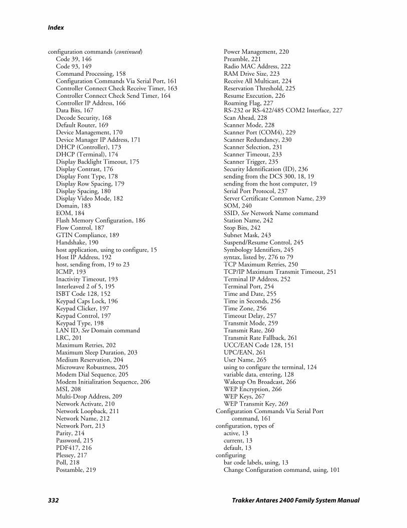
Index
332 Trakker Antares 2400 Family System Manual
configuration commands (continued) Code 39, 146 Code 93, 149 Command Processing, 158 Configuration Commands Via Serial Port, 161 Controller Connect Check Receive Timer, 163 Controller Connect Check Send Timer, 164 Controller IP Address, 166 Data Bits, 167 Decode Security, 168 Default Router, 169 Device Management, 170 Device Manager IP Address, 171 DHCP (Controller), 173 DHCP (Terminal), 174 Display Backlight Timeout, 175 Display Contrast, 176 Display Font Type, 178 Display Row Spacing, 179 Display Spacing, 180 Display Video Mode, 182 Domain, 183 EOM, 184 Flash Memory Configuration, 186 Flow Control, 187 GTIN Compliance, 189 Handshake, 190 host application, using to configure, 15 Host IP Address, 192 host, sending from, 19 to 23 ICMP, 193 Inactivity Timeout, 193 Interleaved 2 of 5, 195 ISBT Code 128, 152 Keypad Caps Lock, 196 Keypad Clicker, 197 Keypad Control, 197 Keypad Type, 198 LAN ID, See Domain command LRC, 201 Maximum Retries, 202 Maximum Sleep Duration, 203 Medium Reservation, 204 Microwave Robustness, 205 Modem Dial Sequence, 205 Modem Initialization Sequence, 206 MSI, 208 Multi-Drop Address, 209 Network Activate, 210 Network Loopback, 211 Network Name, 212 Network Port, 213 Parity, 214 Password, 215 PDF417, 216 Plessey, 217 Poll, 218 Postamble, 219
Power Management, 220 Preamble, 221 Radio MAC Address, 222 RAM Drive Size, 223 Receive All Multicast, 224 Reservation Threshold, 225 Resume Execution, 226 Roaming Flag, 227 RS-232 or RS-422/485 COM2 Interface, 227 Scan Ahead, 228 Scanner Mode, 228 Scanner Port (COM4), 229 Scanner Redundancy, 230 Scanner Selection, 231 Scanner Timeout, 233 Scanner Trigger, 235 Security Identification (ID), 236 sending from the DCS 300, 18, 19 sending from the host computer, 19 Serial Port Protocol, 237 Server Certificate Common Name, 239 SOM, 240 SSID, See Network Name command Station Name, 242 Stop Bits, 242 Subnet Mask, 243 Suspend/Resume Control, 245 Symbology Identifiers, 245 syntax, listed by, 276 to 79 TCP Maximum Retries, 250 TCP/IP Maximum Transmit Timeout, 251 Terminal IP Address, 252 Terminal Port, 254 Time and Date, 255 Time in Seconds, 256 Time Zone, 256 Timeout Delay, 257 Transmit Mode, 259 Transmit Rate, 260 Transmit Rate Fallback, 261 UCC/EAN Code 128, 151 UPC/EAN, 261 User Name, 265 using to configure the terminal, 124 variable data, entering, 128 Wakeup On Broadcast, 266 WEP Encryption, 266 WEP Keys, 267 WEP Transmit Key, 269
Configuration Commands Via Serial Port command, 161
configuration, types of active, 13 current, 13 default, 13
configuring bar code labels, using, 13 Change Configuration command, using, 101
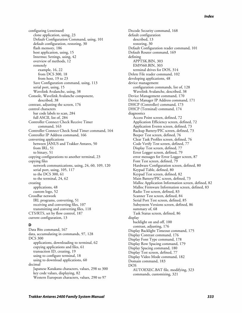
Index
Trakker Antares 2400 Family System Manual 333
configuring (continued) clone application, using, 23 Default Configuration Command, using, 101 default configuration, restoring, 30 flash memory, 186 host application, using, 15 Intermec Settings, using, 42 overview of methods, 12 remotely
example, 16, 22 from DCS 300, 18 from host, 19 to 23
Save Configuration command, using, 113 serial port, using, 15 Wavelink Avalanche, using, 38
Console, Wavelink Avalanche component, described, 38
contrast, adjusting the screen, 176 control characters
bar code labels to scan, 284 full ASCII, list of, 284
Controller Connect Check Receive Timer command, 163
Controller Connect Check Send Timer command, 164 Controller IP Address command, 166 converting applications
between JANUS and Trakker Antares, 50 from IRL, 51 to binary, 51
copying configurations to another terminal, 23 copying files
network communications, using, 24, 60, 109, 120 serial port, using, 105, 117 to the DCS 300, 61 to the terminal, 24, 62
creating applications, 48 custom logo, 52
CrossBar network IRL programs, converting, 51 receiving and converting files, 107 transmitting and converting files, 118
CTS/RTS, set by flow control, 187 current configuration, 13
D Data Bits command, 167 data, accumulating in commands, 97, 128 DCS 300
applications, downloading to terminal, 62 copying applications and files, 61 transaction ID, creating, 19 using to configure terminal, 18 using to download applications, 60
decimal Japanese Katakana characters, values, 298 to 300 key code values, displaying, 82 Western European characters, values, 290 to 97
Decode Security command, 168 default configuration
described, 13 restoring, 30
Default Configuration reader command, 101 Default Router command, 169 defining
APPTSK.BIN, 303 EM9560.BIN, 303 terminal drives for DOS, 314
Delete File reader command, 102 developing applications, 48 device management
configuration commands, list of, 128 Wavelink Avalanche, described, 38
Device Management command, 170 Device Manager IP Address command, 171 DHCP (Controller) command, 173 DHCP (Terminal) command, 174 diagnostics
Access Point screen, defined, 72 Application Efficiency screen, defined, 72 Application Events screen, defined, 73 Backup Battery/PIC screen, defined, 73 Beeper Test screen, defined, 76 Clear Task Profiles screen, defined, 76 Code Verify Test screen, defined, 77 Display Test screen, defined, 77 Error Logger screen, defined, 79 error messages for Error Logger screen, 87 Font Test screen, defined, 79 Hardware Configuration screen, defined, 80 Keypad Table, defined, 80 Keypad Test screen, defined, 82 Main Battery/PIC screen, defined, 73 Malloc Application Information screen, defined, 82 Malloc Firmware Information screen, defined, 83 Radio Test screen, defined, 83 Scanner Test screen, defined, 84 Serial Port Test screen, defined, 85 Subsystem Versions screen, defined, 86 summary of, 68 Task Status screen, defined, 86
display backlight on and off, 100 contrast, adjusting, 176
Display Backlight Timeout command, 175 Display Contrast command, 176 Display Font Type command, 178 Display Row Spacing command, 179 Display Spacing command, 180 Display Test screen, defined, 77 Display Video Mode command, 182 Domain command, 183 DOS
AUTOEXEC.BAT file, modifying, 323 commands, customizing, 321
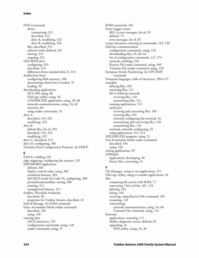
Index
334 Trakker Antares 2400 Family System Manual
DOS (continued) drives
customizing, 321 described, 314 drive A, modifying, 322 drive B, modifying, 324
files, described, 314 software tools, defined, 321 starting, 315 stopping, 321
DOS RAM drive configuring, 325 described, 314 differences from standard drive E, 314
double-byte fonts configuring flash memory, 186 determining which font is loaded, 79 loading, 36
downloading applications DCS 300, using, 60 FileCopy utility, using, 56 LOADER.EXE application, using, 58, 60 network communications, using, 24, 62 overview, 60 using reader commands, 55
drive A described, 314, 322 modifying, 323
drive B default files, list of, 325 described, 314, 324 modifying, 325
drive C, described, 314 drive D, configuring, 186 Dynamic Host Configuration Protocol, See DHCP
E EAN-8, enabling, 261 edge triggering, configuring the scanner, 235 EM9560.BIN application
defined, 303 display control codes, using, 305 emulation features, 304 full ASCII mode for Code 39, configuring, 309 preambles/postambles, setting, 308 running, 311 unsupported features, 311
Enabler, Wavelink Avalanche described, 38 properties for Trakker Antares, described, 42
End of Message, See EOM command Enter Accumulate Mode reader command
described, 103 using, 128
entering data ASCII characters, 129 configuration commands, using, 128 reader commands, using, 97
EOM command, 184 Error Logger screen
802.1x error messages, list of, 93 defined, 79 error messages, list of, 87
escape characters, entering in commands, 129, 130 Ethernet communications
configuration commands, using, 124 downloading files, 24, 60, 62 list of configuration commands, 127, 274 network, enabling, 210 Receive File reader command, using, 109 Transmit File reader command, using, 120
European Article Numbering, See UPC/EAN command
European languages, table of characters, 290 to 97 examples
deleting files, 103 renaming files, 111 RF or Ethernet network
receiving files, 110 transmitting files, 121
running applications, 112 serial port
receiving and converting files, 109 receiving files, 107 remotely configuring the terminal, 16 transmitting and converting files, 120 transmitting files, 118
terminal, remotely configuring, 22 using applications, 312, 313
EXE2ABS.EXE program, using, 51 Exit Accumulate Mode reader command
described, 104 using, 128
exiting applications, 99 EZBuilder
applications, developing, 49 binary files, converting, 51
F File Manager, using to run applications, 311 FileCopy utility, using to transfer applications, 56 files
comparing file system with RAM, 77 converting 7-bit to 8-bit, 107, 118 deleting, 102 listing, 104 receiving, using Receive File command, 105 renaming, 110 transmitting
network communications, using, 24, 60 Transmit File command, using, 116
firmware applications, restarting, 111 Malloc diagnostic screen, defined, 83 upgrading, 31
DOS utility, using, 33, 36
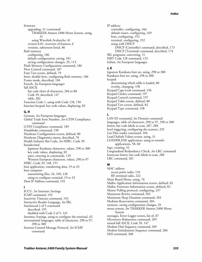
Index
Trakker Antares 2400 Family System Manual 335
firmware upgrading, 31 (continued)
TRAKKER Antares 2400 Menu System, using, 31
using Wavelink Avalanche, 41 version 8.01, overview of features, 6 versions, subsystem listed, 86
flash memory configuring, 186 default configuration, saving, 101 saving configuration changes, 29, 113
Flash Memory Configuration command, 186 Flow Control command, 187 Font Test screen, defined, 79 fonts, double-byte, configuring flash memory, 186 Frame mode, described, 184 French, See European languages full ASCII
bar code chart of characters, 284 to 88 Code 39, described, 147 table, 282
Function Code 1, using with Code 128, 150 function keypad, key code values, displaying, 82
G, H German, See European languages Global Trade Item Number, See GTIN Compliance
command GTIN Compliance command, 189 Handshake command, 190 Hardware Configuration screen, defined, 80 Hardware Diagnostics menu, described, 70 Health Industry Bar Code, See HIBC, Code 39. hexadecimal
Japanese Katakana characters, values, 298 to 300 key code values, displaying, 82 pairs, entering in commands, 129 Western European characters, values, 290 to 97
HIBC, Code 39, 148, 151 host application, transferring data, 19 to 23 host computer
transmitting files, 24, 109, 120 using to configure terminal, 19 to 23
Host IP Address command, 192
I ICCU, See Intermec Settings ICMP command, 193 Inactivity Timeout command, 193 Interactive Reader Language, See IRL Interleaved 2 of 5 command
described, 195 disabled with Code 2 of 5, 145
Intermec Settings, using to configure the terminal, 42 international languages, table of characters, 290 to 97,
298 to 300 Internet Control Message Protocol, See ICMP
command
IP address controller, configuring, 166 default router, configuring, 169 host, configuring, 192 terminal, configuring, 252 using with DHCP
DHCP (Controller) command, described, 173 DHCP (Terminal) command, described, 174
IRL programs, converting, 51 ISBT Code 128 command, 152 Italian, See European languages
J, K Japanese Katakana font set, using, 298 to 300 Katakana font set, using, 298 to 300 keypad
determining which table is loaded, 80 overlay, changing, 198
Keypad Caps Lock command, 196 Keypad Clicker command, 197 Keypad Control command, 197 Keypad Table screen, defined, 80 Keypad Test screen, defined, 82 Keypad Type command, 198
L LAN ID command, See Domain command languages, table of characters, 290 to 97, 298 to 300 letters, bar code labels to scan, 287, 288 level triggering, configuring the scanner, 235 List Files reader command, 104 Load Default Values screen, using, 31 LOADER.EXE application, using to transfer
applications, 58, 60 logo, creating, 52 Longitudinal Redundancy Check, See LRC command lowercase letters, bar code labels to scan, 288 LRC command, 201
M MAC address
access point radio, 134 RF terminal radio, 222
Main Board Menu, using, 76 Malloc Application Information screen, defined, 82 Malloc Firmware Information screen, defined, 83 Master Polling protocol, configuring, 237 Maximum Retries command, 202 Maximum Sleep Duration command, 203 Medium Reservation command, 204 memory, saving configuration changes, 29 menu system, See TRAKKER Antares 2400 Menu
System messages, Error Logger screen, list of, 87 Microwave Robustness command, 205 mixed-full ASCII, Code 39, 147 Modem Dial Sequence command, 205 Modem Initialization Sequence command, 206 MSI command, 208
Index
336 Trakker Antares 2400 Family System Manual
Multi-Drop address, configuring, 209 protocol
configuring, 237 receiving and converting files, 107 transmitting and converting files, 118
Multiple-Read Labels reader command, 104
N Network Activate command, 210 network communications
controller IP address, configuring, 166 default router, configuring, 169 DHCP (Controller), configuring, 173 DHCP (Terminal), configuring, 174 Ethernet network, activating, 210 host IP address, configuring, 192 network port, configuring, 213 protocols, defined, 6 RF network, activating, 210 subnet mask, configuring, 243 terminal IP address, configuring, 252 terminal port, configuring, 254
Network Loopback command, 211 Network Name command, 212 Network Port command, 213 network profiles, Wavelink Avalanche, defined, 40 non-full ASCII, Code 39, 146 nonprintable ASCII characters, entering in
commands, 129 numbers, bar code labels to scan, 286
O One-Shot mode, configuring the scanner, 228 OpenAir network communications
configuration commands, list of, 127, 275 Domain, configuring, 183 Inactivity Timeout, configuring, 193 Roaming Flag, configuring, 227 Security Identification (ID), configuring, 236 Transmit Mode, configuring, 259 Wakeup On Broadcast, configuring, 266 See also RF communications.
operating the terminal configuration commands
list of, 125, 272 using, 124
reader commands enabling or disabling, 158 using, 96
OSI model, network protocols, defining, 6
P package
control files, Wavelink Avalanche, defined, 40 software, Wavelink Avalanche, defined, 39
Parity command, 214
Password command, 215 PDF417 command, 216 Plessey command, 217 PM.COM command, using, 320 POL characters for Multi-Drop addresses, 209 Poll command, 218 Polling Mode D protocol, configuring, 237 port, terminal, configuring, 254 Portuguese, See European languages Postamble command, 219 postamble, EM9560.BIN application, setting, 308 power management
automatic shutoff, using, 135 resume, suspend, and boot, 226 Wakeup On Broadcast, disabling, 266
Power Management command, 220 Preamble command, 221 preamble, EM9560.BIN application, setting, 308 print quality, bar code, 168, 230 profiles, network, Wavelink Avalanche, defined, 40 program, See applications protocol
checking the protocol loaded, 86 configuring, 237 terminal protocol stack, illustrated, 8 Wavelink Avalanche packages, defined, 39
protocol stack, OSI model, defined, 6 PSK
applications, developing, 49 binary files, converting, 51 defined, 49 IRL programs, converting, 51 JANUS and Trakker Antares, converting
applications, 50 See also the Trakker Antares Application Development
Tools System Manual. punctuation marks, bar code labels to scan, 285
Q, R QFSK, defined, 259 quotation marks in commands,
using, 14, 129, 219, 221 Radio MAC Address command, 222 Radio Test screen, defined, 83 radio, troubleshooting, 83 RAM
default configuration, saving, 101 DOS RAM drive
configuring, 325 described, 314 differences from standard drive E, 314
RAM Drive Size command, 223 saving configuration changes, 29 standard drive E, differences from DOS RAM
drive, 314 reader command files
Wavelink Avalanche, defined, 40 Wavelink Avalanche, guidelines for creating, 41
Index
Trakker Antares 2400 Family System Manual 337
reader commands Abort Program, 99 accumulate mode commands, list of, 97 Accumulate mode, using, 97 Backlight On and Off, 100 Backspace, 100 Boot Terminal, 100 Change Configuration, 101 Clear, 101 Default Configuration, 101 Delete File, 102 enabling or disabling, 158 Enter Accumulate Mode, 103 Exit Accumulate Mode, 104 file management commands, list of, 97 host application, using to configure, 15 List Files, 104 Multiple-Read Labels, 104 operating commands, list of, 97 Receive File, 105 Rename File, 110 Reset Firmware, 111 Run Program, 112 Save Configuration, 113 Scanner Trigger On, 113 sending from the DCS 300, 18, 19 sending from the host computer, 19 Set Time and Date, 114 Status Lights Control, 115 TRAKKER Antares 2400 Menu System, 104 Transmit File, 116 using, 96 using to transfer applications, 55
Receive All Multicast command, 224 Receive File reader command, 105 Rename File reader command, 110 Reservation Threshold command, 225 Reset Firmware reader command, 111 resetting the terminal
default configuration, restoring, 30 Reset Firmware command, described, 111
Resume Execution command, 226 RF communications
acknowledgement delay lower limit, configuring, 131
acknowledgement delay upper limit, configuring, 132
activating the RF network, 210 configuration commands, list of, 127, 274 configuration commands, using, 124 controller connect check receive timer,
configuring, 163 controller connect check send timer,
configuring, 164 controller IP address, configuring, 166 default router, configuring, 169 device management commands, list of, 128 DHCP (Controller), configuring, 173
DHCP (Terminal), configuring, 174 downloading files, 24, 60, 62 host IP address, configuring, 192 maximum retries, configuring, 202 network port, configuring, 213 protocols, defined, 6 Receive File reader command, using, 109 security
802.1x commands, list of, 128 WEP commands, list of, 128 See also your terminal user’s manual.
subnet mask, configuring, 243 TCP maximum retries, configuring, 250 TCP/IP maximum transmit timeout,
configuring, 251 terminal IP address, configuring, 252 terminal port, configuring, 254 transferring files, 60 Transmit File reader command, using, 120 See also 802.11b network communications. See also OpenAir network communications.
RF network protocol, checking the protocol loaded on the terminal, 86
Roaming Flag command, 227 ROM-DOS
BIOS interfaces, list of, 327 commands
list of, 318 to 20 using, 317
described, 313 limitations of, 327 See also DOS.
row spacing, configuring, 179, 180 RS-232 or RS-422/485 COM2 command, 227 Run Program reader command, 112 running applications
DOS, 316 overview, 65
S Save Configuration in Flash Memory command, 113 saving configuration changes
flash memory, 29 reader command, using, 113
Scan Ahead command, 228 scan codes, Western European characters,
values, 290 to 97 scanner
configuring for input devices, 231 testing, 84
Scanner Mode command, 228 Scanner Port (COM4) command, 229 Scanner Redundancy command, 230 Scanner Selection command, 231 Scanner Test screen, defined, 84 Scanner Timeout command, 233 Scanner Trigger command, 235 Scanner Trigger On and Off reader command, 113
Index
338 Trakker Antares 2400 Family System Manual
scanning ASCII characters, list of labels, 284 to 88 button/trigger operation, configuring, 228 reader commands, using, 113 Scan Ahead command, configuring, 228 timeout, configuring, 233
screen, troubleshooting with Display Test diagnostic, 77
security 802.1x commands, list of, 128 WEP commands, list of, 128 See also your terminal user’s manual.
Security Identification (ID) command, 236 SEL characters for Multi-Drop addresses, 209 selection criteria, Wavelink Avalanche, described, 41 serial port
configuration commands, list of, 126, 274 configuring Scanner port as COM4, 229 protocol, configuring, 237 Receive File reader command, 105, 107 RS-232 or RS-422/485, choosing, 227 Transmit File reader command, 117, 118 using to configure the terminal, 15 using to transfer applications, 55
serial port communications Baud Rate, configuring, 136 Configuration Commands Via Serial Port,
configuring, 161 Data Bits, configuring, 167 EOM, configuring, 184 Flow Control, configuring, 187 Handshake, configuring, 190 LRC, configuring, 201 Multi-Drop Address, configuring, 209 Parity, configuring, 214 Poll, configuring, 218 RS-232 or RS-422/485 COM2 Interface,
configuring, 227 Serial Port Protocol, configuring, 237 SOM, configuring, 240 Stop Bits, configuring, 242 Timeout Delay, configuring, 257
Serial Port Test screen, defined, 85 Server Certificate Common Name command, 239 Set Time and Date reader command, 114 Simulator, See Application Simulator software
collection, Wavelink Avalanche, defined, 39 package, Wavelink Avalanche, defined, 39
software diagnostics Application Events screen, defined, 73 Clear Task Profiles screen, defined, 76 Error Logger screen, defined, 79 Font Test screen, defined, 79 Keypad Table screen, defined, 80 Task Status screen, defined, 86
Software Diagnostics menu, described, 70 SOM command, 240
Spanish, See European languages SSID command, See Network Name command Start of Message, See SOM command starting
applications, 65, 311 TRAKKER Antares 2400 Menu System, 104
Station Name command, 242 Status Lights Control reader command, 115 Stop Bits command, 242 Store Configuration screen, using, 29 Subnet Mask command, 243 Subsystem Versions screen, defined, 86 Suspend mode, automatic shutoff, using, 135 Suspend/Resume Control command, 245 Symbology Identifiers command, 245 symbols, bar code labels to scan, 285 synchronization properties, Wavelink Avalanche,
described, 41, 42 syntax, configuration commands listed by, 276 to 79 system diagnostics
Access Point screen, defined, 72 Application Efficiency screen, defined, 72 Code Verify Test screen, defined, 77 Malloc Application Information screen, defined, 82 Malloc Firmware screen, defined, 83 Serial Port Test screen, defined, 85 Subsystem Versions screen, defined, 86
System Diagnostics menu, described, 70 system message flag, defined, 20
T Task Status screen, defined, 86 TCP Maximum Retries command, 250 TCP/IP direct connect network
checking the protocol loaded, 86 CLIENT.CPP sample application, 26 firmware, upgrading, 31 protocols, defined, 6 reader commands, using, 96 transmitting files, 24, 109, 120
TCP/IP Maximum Transmit Timeout command, 251 TE 2000, See terminal emulation terminal
2400 Family, described, 2 applications
developing, 48 downloading, 24, 62
characters, table of, 290 to 97, 298 to 300 configuring
bar code labels, using, 13 clone application, using, 23 from DCS 300, 18 from host, 19 to 23 from host computer, 19 overview of methods, 12 serial port, using, 15 using Intermec Settings, 42 using Wavelink Avalanche, 38
default configuration, list of, 272
Index
Trakker Antares 2400 Family System Manual 339
terminal (continued) diagnostics, using, 68 DOS architecture, 328 double-byte fonts, loading, 36 firmware
upgrading, 31, 41 version 8.01, overview of features, 6
protocol stack, illustrated, 8 Terminal Download Configuration dialog box, 62 terminal emulation
choosing the TE 2000 configuration, 302 See also the TE 2000 5250 Terminal Emulation
Programmer’s Guide, the TE 2000 3270 Terminal Emulation Programmer’s Guide, or the TE 2000 VT/ANSI Terminal Emulation Programmer’s Guide.
Terminal IP Address command, 252 Terminal Port command, 254 Test and Service Mode reader command, See
TRAKKER Antares 2400 Menu System reader command
TFTP defined, 7 server, using, 25
Thai language font option, 36 Time and Date command, 255 Time in Seconds command, 256 Time Zone command, 256 Timeout Delay command, 257 timeout, configuring for scanner, 233 TMF protocol
configuration commands, using with, 162 configuring remotely
described, 19 to 23 example, 16
defined, 7 fields, defined, 15, 20, 21
TRAKKER Antares 2400 Menu System accessing with TRAKKER Antares 2400 Menu
System command, 104 applications, running, 65 default configuration, restoring, 30 Diagnostics Menu, using, 69 firmware, upgrading, 31 flash memory, saving changes, 29
TRAKKER Antares 2400 Menu System reader command, 104
Trakker Antares Enabler properties, Wavelink Avalanche, described, 42
Trakker Antares FileCopy utility, See FileCopy utility transaction header, defined, 20 transaction ID, creating, 19 transferring applications and files
using reader commands, 55 using the DCS 300, 60 using the FileCopy utility, 56 using the LOADER.EXE application, 58, 60
Transmit File reader command, 116 Transmit Mode command, 259 Transmit Rate command, 260 Transmit Rate Fallback command, 261 troubleshooting
diagnostics, summary of, 68 to 69 error messages, list of, 87 to 93 See also your terminal user’s manual.
U UCC/EAN Code 128 command
described, 151 GTIN Compliance, 152
UDP Plus network checking the protocol loaded, 86 firmware, upgrading, 31 protocol, defined, 7 reader commands, using, 96 transmitting files, 60, 109, 120
UDP Port, See Network Port command Universal Product Code, See UPC/EAN command Universal Time, Time Zone command, 256 UPC/EAN command
described, 261 GTIN Compliance, 263
UPC-A/EAN-13, enabling, 261 UPC-E, enabling, 261 upgrading the terminal
loading double-byte fonts, 36 overview of methods, 32 upgrading the firmware
DOS utility, using, 33, 36 Wavelink Avalanche upgrade files, 41
uppercase letters, bar code labels to scan, 287 User Defined status light, programming, 115 User Name command, 265 USERINIT.BMP, creating a custom logo, 52 UTILS.H Utility, CLIENT.CPP sample application,
28
V, W variable data, entering in commands, 97, 128 volume, adjusting, 138, 139, 141 voting, Scanner Redundancy command, 230 Wakeup On Broadcast command, 266 warm boot, 111 Wavelink Avalanche
components, 38 described, 38 Device Management command, 170 Device Manager IP command, 171 Enabler
described, 38 Trakker Antares properties, described, 42
network profiles, defined, 40 package
control files, defined, 40 defined, 39
Index
340 Trakker Antares 2400 Family System Manual
Wavelink Avalanche (continued) reader command files
defined, 40 guidelines for creating, 41
selection criteria, described, 41 software collection, defined, 39 software package, defined, 39 synchronization properties, described, 41 Trakker Antares protocol packages, defined, 39 upgrade files, defined, 41
WEP Encryption command, 266 WEP Keys command, 267 WEP Transmit Key command, 269 Western European languages, See European languages Wi-Fi certified, 2
WTP network checking the protocol loaded, 86 protocol stack, illustrated, 8 protocol, defined, 10 reader commands, using, 96 See also the TE 2000 5250 Terminal Emulation
Programmer’s Guide, TE 2000 3270 Terminal Emulation Programmer’s Guide, or the TE 2000 VT/ANSI Terminal Emulation Programmer’s Guide.
X, Y XMODEM protocol, described, 105, 117 XMODEM-1K protocol
described, 105, 117 using for the clone application, 23
XON/XOFF, set by flow control, 187 YMODEM protocol, described, 105, 117

Corporate Headquarters6001 36th Avenue WestEverett, Washington 98203U.S.A.
tel 425.348.2600
fax 425.355.9551
www.intermec.com
Trakker Antares 2400 Family System Manual
*071389-006*P/N 071389-006
Trakker Antares®
Firmware Version 8.02
Addendum
ii Trakker Antares Firmware Version 8.02 Addendum
Intermec Technologies Corporation
Corporate Headquarters 6001 36th Ave. W. Everett, WA 98203 U.S.A.
www.intermec.com
The information contained herein is proprietary and is provided solely for the purpose of allowing customers to operate and service Intermec-manufactured equipment and is not to be released, reproduced, or used for any other purpose without written permission of Intermec.
Information and specifications contained in this document are subject to change without prior notice and do not represent a commitment on the part of Intermec Technologies Corporation.
© 2005 Intermec Technologies Corporation. All rights reserved.
The word Intermec, the Intermec logo, Norand, ArciTech, Beverage Routebook, CrossBar, dcBrowser, Duratherm, EasyADC, EasyCoder, EasySet, Fingerprint, INCA (under license), i-gistics, Intellitag, Intellitag Gen2, JANUS, LabelShop, MobileLAN, Picolink, Ready-to-Work, RoutePower, Sabre, ScanPlus, ShopScan, Smart Mobile Computing, SmartSystems, TE 2000, Trakker Antares, and Vista Powered are either trademarks or registered trademarks of Intermec Technologies Corporation.
Throughout this manual, trademarked names may be used. Rather than put a trademark (™ or ®) symbol in every occurrence of a trademarked name, we state that we are using the names only in an editorial fashion, and to the benefit of the trademark owner, with no intention of infringement.
There are U.S. and foreign patents pending.
Wi-Fi is a registered certification mark of the Wi-Fi Alliance.
Microsoft, Windows, and the Windows logo are registered trademarks of Microsoft Corporation in the United States and/or other countries.
Bluetooth is a trademark of Bluetooth SIG, Inc., U.S.A.
This product includes software developed by the OpenSSL Project for use in the OpenSSL Toolkit. (www.opensssl.org).
This product includes cryptographic software written by Eric Young ([email protected]).
Contents
Trakker Antares Firmware Version 8.02 Addendum iii
Contents How to Use This Addendum............................................................................................... 5
File System Enhancements................................................................................................... 6 Flash Memory Configuration Command................................................................ 6 Double-Byte Font Support ..................................................................................... 7 Font Test Diagnostic Update.................................................................................. 8
Wavelink Avalanche Update ................................................................................................ 9
802.1x LEAP Security Change............................................................................................. 9
Time Zone Configuration Command................................................................................ 10
Keypad Type Configuration Command............................................................................. 11
Keypad Table Diagnostic................................................................................................... 11

Contents
iv Trakker Antares Firmware Version 8.02 Addendum
Trakker Antares Firmware Version 8.02 Addendum 5
How to Use This Addendum Read this addendum before you start using your Trakker Antares® terminal. This addendum contains the latest information for Trakker Antares firmware version 8.02.
The firmware on Trakker Antares terminals has been updated to provide added features and improve efficiency and ease of use. These changes are not reflected in the user’s manual, but they are described here in detail.
The information in this addendum applies to the Trakker Antares 241X, 242X, 243X, 2455, 2475, and 248X terminals. For more information about using the terminals, refer to your user’s manual or system manual.
Trakker Antares Manuals
Manual Part Number
Trakker Antares 241X Handheld Terminal User’s Manual 069538
Trakker Antares 242X Handheld Terminal User’s Manual 064024
Trakker Antares 243X Handheld Terminal User’s Manual 071791
Trakker Antares 2455 Vehicle-Mount Terminal User’s Manual 067358
Trakker Antares 2475 Vehicle-Mount Terminal User’s Manual 072383
Trakker Antares 248X Stationary Terminal User’s Manual 066960
Trakker Antares 2400 Family System Manual 071389
Note: This addendum does not apply to the Trakker Antares 246X Stationary terminal. The 246X only supports firmware version 6.2X and earlier. For help using the 246X terminal, see the Trakker Antares 246X Stationary Terminal User’s Manual (P/N 068575).
If there are any conflicts between the information in the Trakker Antares user’s manual or system manual and this addendum, use the information in this addendum.
If you have an earlier version of firmware, you can download version 8.02 at no charge from the Intermec web site at www.intermec.com. If you are using firmware version 8.01 or earlier and you are not going to upgrade to firmware version 8.02, use your Trakker Antares user’s manual and system manual and disregard this addendum.
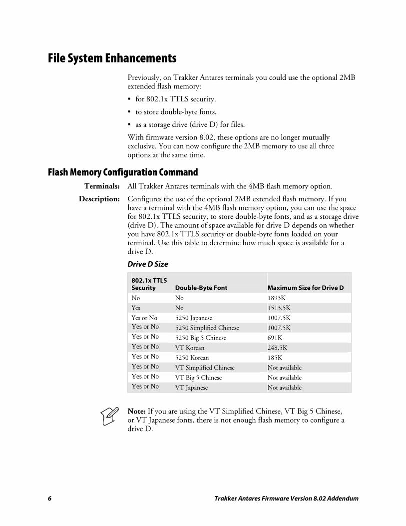
6 Trakker Antares Firmware Version 8.02 Addendum
File System Enhancements Previously, on Trakker Antares terminals you could use the optional 2MB extended flash memory:
• for 802.1x TTLS security.
• to store double-byte fonts.
• as a storage drive (drive D) for files.
With firmware version 8.02, these options are no longer mutually exclusive. You can now configure the 2MB memory to use all three options at the same time.
Flash Memory Configuration Command Terminals: All Trakker Antares terminals with the 4MB flash memory option.
Description: Configures the use of the optional 2MB extended flash memory. If you have a terminal with the 4MB flash memory option, you can use the space for 802.1x TTLS security, to store double-byte fonts, and as a storage drive (drive D). The amount of space available for drive D depends on whether you have 802.1x TTLS security or double-byte fonts loaded on your terminal. Use this table to determine how much space is available for a drive D.
Drive D Size
802.1x TTLS Security
Double-Byte Font
Maximum Size for Drive D
No No 1893K
Yes No 1513.5K
Yes or No 5250 Japanese 1007.5K Yes or No 5250 Simplified Chinese 1007.5K Yes or No 5250 Big 5 Chinese 691K Yes or No VT Korean 248.5K Yes or No 5250 Korean 185K Yes or No VT Simplified Chinese Not available Yes or No VT Big 5 Chinese Not available Yes or No VT Japanese Not available
Note: If you are using the VT Simplified Chinese, VT Big 5 Chinese, or VT Japanese fonts, there is not enough flash memory to configure a drive D.
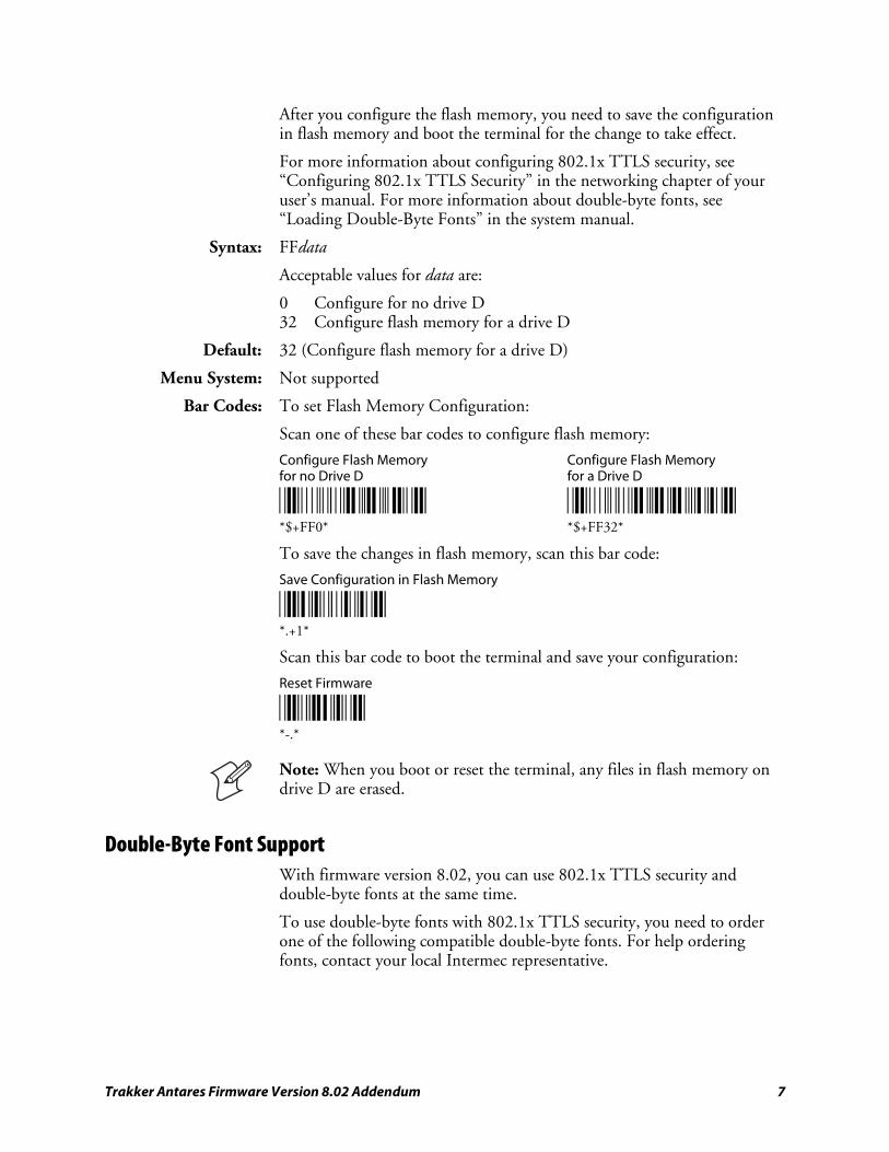
Trakker Antares Firmware Version 8.02 Addendum 7
After you configure the flash memory, you need to save the configuration in flash memory and boot the terminal for the change to take effect.
For more information about configuring 802.1x TTLS security, see “Configuring 802.1x TTLS Security” in the networking chapter of your user’s manual. For more information about double-byte fonts, see “Loading Double-Byte Fonts” in the system manual.
Syntax: FFdata
Acceptable values for data are:
0 Configure for no drive D 32 Configure flash memory for a drive D
Default: 32 (Configure flash memory for a drive D)
Menu System: Not supported
Bar Codes: To set Flash Memory Configuration:
Scan one of these bar codes to configure flash memory:
Configure Flash Memory Configure Flash Memory for no Drive D for a Drive D
*$+FF0* *$+FF32* *$+FF0* *$+FF32*
To save the changes in flash memory, scan this bar code:
Save Configuration in Flash Memory
*.+1* *.+1*
Scan this bar code to boot the terminal and save your configuration:
Reset Firmware
*-.* *-.*
Note: When you boot or reset the terminal, any files in flash memory on drive D are erased.
Double-Byte Font Support With firmware version 8.02, you can use 802.1x TTLS security and double-byte fonts at the same time.
To use double-byte fonts with 802.1x TTLS security, you need to order one of the following compatible double-byte fonts. For help ordering fonts, contact your local Intermec representative.
8 Trakker Antares Firmware Version 8.02 Addendum
Double-Byte Fonts Compatible With 802.1x TTLS Security
Language File Name
Simplified Chinese, VT 24DBCTSS.FON
Simplified Chinese, 5250 24DBCLSS.FON
Big 5 Chinese, VT 24DBTTSS.FON
Big 5 Chinese, 5250 24DBTLSS.FON
Japanese EUC (unix), VT 24DBJTSS.FON
Japanese, 5250 24DBJLSS.FON
Korean, VT 24DBKTSS.FON
Korean, 5250 24DBKLSS.FON
Note: If you are using the VT Simplified Chinese, VT Big 5 Chinese, or VT Japanese fonts, there is not enough flash memory to configure a drive D.
For more information about loading double-byte fonts on your Trakker Antares terminal, see “Loading Double-Byte Fonts” in the system manual. If you do not need 802.1x TTLS security, you can use either the original double-byte font files or the new files listed above.
Font Test Diagnostic Update The font test diagnostic identifies which double-byte font, if any, you have loaded on your terminal. Firmware version 8.02 provides support for double-byte fonts that are compatible with 802.1x TTLS security. These fonts have different font file names than previously released double-byte fonts.
Use this table to match the font number with the double-byte font that is loaded on your terminal.
Double-Byte Font and Font Number
Font Number
Double-Byte Font
Current Font File Name
802.1x TTLS Security Font File Name
1 Simplified Chinese, VT 24DBCSCT.FON 24DBCTSS.FON
2 Japanese, 5250 24DBCSJL.FON 24DBJLSS.FON
4 Korean, VT 24DBCSKT.FON 24DBKTSS.FON
5 Korean, 5250 24DBCSKL.FON 24DBKLSS.FON
8 Big 5 Chinese, VT 24DBCSTT.FON 24DBTTSS.FON
9 Japanese EUC (unix), VT 24DBCSJT.FON 24DBJTSS.FON
11 Big 5 Chinese, 5250 24DBCSTL.FON 24DBTLSS.FON
13 Simplified Chinese, 5250 24DBCSCL.FON 24DBCLSS.FON
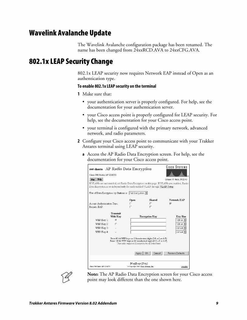
Trakker Antares Firmware Version 8.02 Addendum 9
Wavelink Avalanche Update The Wavelink Avalanche configuration package has been renamed. The name has been changed from 24xxRCD.AVA to 24xxCFG.AVA.
802.1x LEAP Security Change 802.1x LEAP security now requires Network EAP instead of Open as an authentication type.
To enable 802.1x LEAP security on the terminal
1 Make sure that:
• your authentication server is properly configured. For help, see the documentation for your authentication server.
• your Cisco access point is properly configured for LEAP security. For help, see the documentation for your Cisco access point.
• your terminal is configured with the primary network, advanced network, and radio parameters.
2 Configure your Cisco access point to communicate with your Trakker Antares terminal using LEAP security.
a Access the AP Radio Data Encryption screen. For help, see the documentation for your Cisco access point.
Note: The AP Radio Data Encryption screen for your Cisco access point may look different than the one shown here.
10 Trakker Antares Firmware Version 8.02 Addendum
b Check the Network-EAP check box for Accept Authentication Type.
c Click OK.
3 On your Trakker Antares terminal, set the User Name and Password parameters.
a Scan this bar code to access the TRAKKER Antares 2400 Menu System:
TRAKKER Antares 2400 Menu System
*..-.* *..-.*
The Main Menu appears.
b Choose Configuration Menu > Communications Menu > Radio.
c Use the arrow keys to scroll to the LEAP screen and set the User Name and Password parameters.
If you just want to make sure that your terminal can be authenticated, you can use the default values of “anonymous” and “anonymous.” However, Intermec recommends that you set your permanent user name and password to unique values. For help, see Chapter 6, “Configuration Command Reference,” in the 2400 Family system manual.
4 Exit the menu system and save all changes.
5 When the terminal is authenticated, it emits a low beep and then a high beep. The application that was running on the terminal, if any, resumes.
If authentication fails, the terminal emits a high beep and then a low beep. The terminal waits 60 seconds and restarts the authentication process.
Time Zone Configuration Command Terminals: 241X, 242X, 243X, 2455, 2475, and 248X.
Description: The Time Zone configuration command sets the time zone on Trakker Antares terminals. With firmware version 8.02, you can now set the time zone using positive or negative values from -14 to +14 in increments of 15 minutes from 0, which represents Universal Time (UT).
Syntax: DZdata
Acceptable values for data are:
+/- + or - Positive or negative hh 0 to 14 Hours :mm 15, 30, or 45 Minutes (optional)
Menu System: Not supported
Trakker Antares Firmware Version 8.02 Addendum 11
Bar Codes: To set the default time zone, scan this bar code:
Set Time Zone to Pacific Standard Time
*$+DZ-8* *$+DZ-8*
Note: To set the time zone to a value other than the default value, use Wavelink Avalanche.
Keypad Type Configuration Command Terminals: 243X
Description: The keypad type is initially configured in the terminal’s firmware at the Intermec factory. If you change the keypad overlay, you need to configure the keypad type to match the new keypad overlay.
Syntax: KTdata
where acceptable values for data are listed in the next table. These additional values are available for the 243X 48-key keypad.
Keypad Type Acceptable Values for Data
Value Description
a Programmable, 48-key, 243X
b International, 48-key, 243X
c TE 2000, 48-key, 243X
Keypad Table Diagnostic The keypad table diagnostic helps Intermec service personnel to identify the number of the keypad table that you have loaded on your terminal. The hexadecimal (hex) code displayed on the screen indicates which keypad table is loaded. The following hex codes identify keypad tables for the 243X 48-key keypad.
Keypad Table Hex Code Description
Hex Description
0x35 Programmable, 48-key, 243X
0x36 International, 48-key, 243X
0x37 TE 2000, 48-key, 243X

Corporate Headquarters6001 36th Avenue WestEverett, Washington 98203U.S.A.tel 425.348.2600fax 425.355.9551www.intermec.com
Trakker Antares Firmware Version 8.02 Addendum
*941-000-001*P/N 941-000-001