read completely before quoting repower - … · read completely before quoting repower ... install...
TRANSCRIPT

ATTENTION READ COMPLETELY BEFORE QUOTING REPOWER
As in any “REPOWER”, experience has shown that a piece of equipment designed for older Tier 0 or Tier 1 model engines almost always has trade-offs and compromises when installing a newer Tier 2 or Tier 3 model engine. Please be aware that the equipment options on your candidate machine many differ from the options on the machine this kit was developed on. Examples might include but are not limited to, the presence of air conditioning, serial number breaks, adaptation components, additional components and /or alternate components. Due to these circumstances and with respect to the “best way” and/or individual interpretations to execute a repower, Bell Power Systems will not be responsible for any additional installation cost incurred. Before quoting, review the repower instructions, components supplied and engine option codes to get a full understanding what is required to perform this repower. If you identify any areas of concern or have any question please contact Bell Power Systems engineering department at 1-800-225-8669 or [email protected]. They will work with you to develop a more complete understanding of the scope of this repower project.

PLEASE READ ALL INSTRUCTIONS THOROUGHLY BEFORE STARTING REPOWER
WWW.BELLPOWER.COM
INSTRUCTION PACKET
TIER 3 ENGINE REPOWER KIT
744H FOUR-WHEEL DRIVE LOADER

BELL POWER SYSTEMS INSTALLATION INSTRUCTIONS TIER 3 REPOWER 744H LOADER
INST744H 1
Engine Prep
1. Install (1) BELL859 Pilot bushing into center of new RE37275 flywheel. Mount (1) BELL858 torque converter adaptor ring to the flywheel using (12) L34375 3/8" x 1" tapered head bolts(torque 46 lb-ft). Apply medium strength thread locker to the (6) R521465 M12 x 40 flange bolts and mount to the flywheel(torque to 86 lb-ft). (See picture 1)
2. Remove the straight o-ring fitting from the primary fuel filter inlet and install fitting #61M5035 o-ring swivel to Flat face o-ring 90 deg. elbow in its place and thread hose #AT368678 onto it. Join fittings T78646 3/8" NPT to 3/8" o-ring and X6-6GTX-S 3/8" F NPT to 3/8" Male 37 deg. flare together then to AT368678 fuel hose. Do not tighten the hose until the engine is installed and the adapter fitting X6-6GTX-S is secured to the in-line fuel filter. Note: The short hose and check valve from the in-line filter are no longer used.
3. Remove the short 90 deg. fuel return line between the fuel rail and high pressure pump. Install (1) 61H1030 tee fitting at the high pressure pump and re-install the short return line per photo. (See picture 2)
4. Drain and remove the oil pan and pump intake from the new engine. Install the (1) R504228 intake support with (2) R114358 spacers and (2) 19M7813 M12 x 45 bolts. Install (1) R507494 intake to the pump(torque to 30 lb-ft). Secure intake clamp to support with (1) 19M7867 M8 x 25 bolt and (1) 14M7601 M8 flange nut. Clean oil pan mounting surface thoroughly. See Drawing #744H-Oil Pan.
5. Apply gasket sealer to the timing gear cover, rear of the block and rear oil seal housing. Place (1) RE520777 oil pan gasket over the oil pan and install it re-using (6) of the (8) M10 x 45 bolts(discard the other 2). Finish installing the pan with (18) 19M7813 M12 x 45 bolts. Torque: M12- 96 lb-ft, M10- 54 lb-ft. Refill the pan. Top-off with TY22042 10W-30 break-in oil as necessary.
6. Disconnect the coolant line between the thermostat housing and turbo actuator at the actuator. Remove and replace the straight fitting with (1) RE523864 45 deg. fitting. Reconnect the line. (See picture 3)
7. Remove the 1/2" pipe plug from the water pump inlet. Assemble and install (1) 33508 45 deg. elbow with (1) 322086 1/2"-3/8" NPT bushing and (1) 1423 3/8" hose shut-off in its place. (See picture 2)
8. Remove the large plug from the left side of the block. Install (1) U13639 o-ring to (1) R123616 fitting then into the side of the block. Install (1) AT174697 90 deg. barb fitting.
9. Remove the 3/4" pipe plug from the left side of the thermostat housing and install (1) T222360 3/4" NPT to 5/16" hose in its place.

BELL POWER SYSTEMS INSTALLATION INSTRUCTIONS TIER 3 REPOWER 744H LOADER
INST744H 2
10. Install (1) BELL851L left CAC support and (1) BELL857L left front engine mount using (4) 19M7845 M16 x 90 flange bolts. Repeat process for (1) BELL851R right CAC support and (1) BELL857R right front engine mount. Bolt on (1) BELL852 cross member using (4) 19M7791 M12 x 40 flange bolts and (4) 14M7299 nuts (See picture 4). Place (2) BELL856 rubber straps on the cross member at the holes located on each end(1 per side). Set AH217565 Charge Air Cooler onto the cross member. Take BELL855B and BELL855F hold downs and apply #93625K65 weather-stripping to them(CAC contact sides). Assemble the hold downs per drawing# 744H-CAC and secure them and the CAC to the cross member using (4) 14M7601 M8 prevailing nuts and (4) 24H1136 5/16" flat washers.
11. Install BELL853 left upper CAC bracket by removing the bolt near the idler pulley (See picture 5) and replacing it with (1) 19M7812 M10 x 100 flange bolt and medium strength thread locker. Secure the bracket to the CAC using (2) 19M7785 M10 x 25 blots, (2) 14M7518 M10 prevailing nuts and (2) 24H1305 3/8" flat washers.
12. Install BELL854 right upper CAC bracket by removing the lower bolt of the alternator pivot support and replacing it with (1) 19M7835 M10 x 35 flange bolt. Secure the bracket to the CAC with (2) 19M7785 M10 x 25 flange bolts, (2) 14M7518 M10 prevailing nuts and (2) 24H1305 3/8" flat washers. (See picture 6)
13. Install R134525 air conditioning compressor support, upper and lower idler pulleys and A/C compressor. Install R135609 fan belt.
14. Mount BEL013801 fan with (6) H132452 M10 x 200 flange bolts, (1) R128767 and (1) R100676 fan spacers.
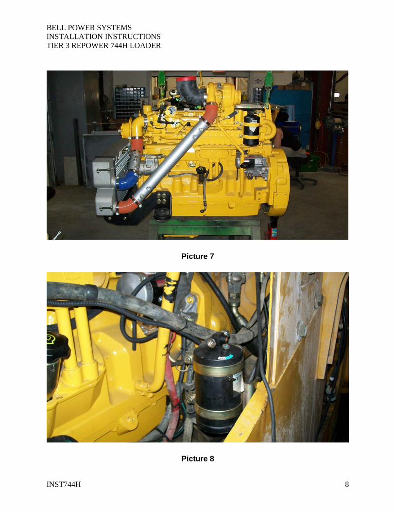
15. Install BELL849 upper and BELL850 lower CAC tubes (See picture 7) using (3) H217412 45 deg. hoses, (1) TP1177000 90 deg. hose and (8) CT350L clamps.
16. Transfer the original engine wiring harness to the new engine. 17. Remove the 1/8" NPT plug forward of the new engine oil pressure sender and
install the original oil pressure sender in its place. 18. Remove the 3/4" pipe plug from the water pump inlet and install (1) BELL891
3/4" to M14 x 1.5 fitting. Transfer one of the temperature sensors over from the original engine.
19. Install and secure the engine to the machine.

BELL POWER SYSTEMS INSTALLATION INSTRUCTIONS TIER 3 REPOWER 744H LOADER
INST744H 3
Machine Prep
1. Install A/C dryer and AT207103 dryer mount on the machine at the (2) chassis mounting points using (2) 19M7785 M10 x 25 flange bolts (See picture 8). Install AT210781 hose and (2) R10093 o-rings from the dryer to the condenser once the engine is installed.
2. Install BELL865 & BELL866 upper and lower fan shrouds using (10) 19M7784 M10 x 20 flange bolts and (4) R112268 5/16" x 3/4" flange bolts.
3. Install BELL868L & BELL868R left and right fan guard supports along with BELL867 fan guard using (8) 19H3771 3/8" x 1" flange bolts, (8) 24H1622 3/8" flat washers and (8) 14H1090 3/8" flange nuts.
4. Install BELL860 upper coolant pipes using (1) 7840 45 deg. hose (thermostat to pipe), (1) 6" length of 639 green stripe hose and (4) HC844 hose clamps (See photo 9). Install (1) 05705BC02 1/8" NPT-5/16" hose elbow. Install (4') TY22324 5/16" hose between 05705BC02 fitting and the T222360 fitting at the thermostat housing. Use (2) HC84M hose clamps to secure the hose
5. Install BELL861 lower coolant pipe using (1) 7840 45 deg. hose, (1) 6" length of 639 green stripe hose and (4) HC844 hose clamps. (See photo 10)
Hood Prep
1. Take the hood off and flip over. Use pictures 11 & 12 to mark and drill the holes for the (2) RE68642 muffler mounts and exhaust stack. Use (4) 19M7785 M10 x 25 flange bolts and (4) 14M7296 M10 nuts for the muffler brackets. Use (4) 19M7785 M10 x 25 flange bolts and (4) 14M7296 nuts to secure (1) BELL864 cover plate over the original stack hole. Note: it may be necessary to move the air filter back slightly.
2. Install the hood. Install (1) BELL863C elbow to the muffler outlet using (1) 90878A accu seal clamp. Install the (1) AZ46687 muffler. Connect the turbo to the muffler using (1) BELL863A and (1) BELL863B pipes, (2) AT222597 and (1) 89526K clamps.
3. Connect the air cleaner to the turbo using BELL862 pipe, (2) HC888 hose clamps, (1) HC896 hose clamp and (1) 90L60R50 5"-6" cobra elbow. (See picture 9)

BELL POWER SYSTEMS INSTALLATION INSTRUCTIONS TIER 3 REPOWER 744H LOADER
INST744H 4
Wiring/Cab
1. Remove the center air duct louvers from the dash. Place (1) BELL705 PV101A mounting bracket on top of the dash and drill out the holes. Bolt the bracket to the dash using (2) 19M7775 M6 x 16 flange bolts and (2) 14M7303 M6 flange nuts.
2. Drill a 3/4" hole in the lower outside corner of the console for the PV101A wiring. 3. Install (1) PV101A Power View panel into the BELL705 bracket and plug (1)
BELL713A harness into the "A" socket on the back of the PV101.Plug (1) PVJR terminating resistor into socket "B". Run the wire harness down the back of the dash to the floor and along the edge of the cab under the floor mat towards the console. Feed the harness through the hole drilled in step 2.
4. Locate wire # P35 and P47 hanging in the rear of the load center under the fuse panel. Remove dust covers.
5. Connect wires to the 21-pin connector. Connect wire #P47 to cavity "G" and wire #P35 to cavity "B" in the 21-pin connector.
6. Locate wire #A02 in the 2-pole connector next to the transmission ECU and remove dust cap. Remove the rubber plug from cavity "A" and install the black wire from cavity "E" in the 21-pin connector.
7. Locate the 3-wire plug from the inverter. Remove the dust cover. Remove the rubber plugs from cavities "A" and "C". Install the red wire from the PV101 harness into cavity "C" and install the black wire into cavity "A".
8. Install the CAN wires from the BELL713A harness into the 21-pin connector. CAN high into cavity "V", CAN low into cavity "U" and shield wire into cavity "F".
9. Locate wires # P20, E11 and R09 in 40-pin connector(old engine harness). Connect P20 to cavity "M", E11 to cavity "L" and R09 to cavity "C" in the 21-pin connector.

BELL POWER SYSTEMS INSTALLATION INSTRUCTIONS TIER 3 REPOWER 744H LOADER
INST744H 5
Picture 1
Picture 2

BELL POWER SYSTEMS INSTALLATION INSTRUCTIONS TIER 3 REPOWER 744H LOADER
INST744H 6
Picture 3
Picture 4

BELL POWER SYSTEMS INSTALLATION INSTRUCTIONS TIER 3 REPOWER 744H LOADER
INST744H 7
Picture 5
Picture 6
BELL POWER SYSTEMS INSTALLATION INSTRUCTIONS TIER 3 REPOWER 744H LOADER
INST744H 8
Picture 7
Picture 8

BELL POWER SYSTEMS INSTALLATION INSTRUCTIONS TIER 3 REPOWER 744H LOADER
INST744H 9
Picture 9
Picture 10

BELL POWER SYSTEMS INSTALLATION INSTRUCTIONS TIER 3 REPOWER 744H LOADER
INST744H 10
Picture 11
Picture 12

BELL POWER SYSTEMS INSTALLATION INSTRUCTIONS TIER 3 REPOWER 744H LOADER
INST744H 11
Picture 13

Page 1New Design
6/16/2010 2:11:18 PMfile://localhost/F:/Dan/New%20Design.mht
Product Configurator Home
John Deere Power Systems
NA Distributor ExtranetSaran Distributor ExtranetContact Us
Welcome X785880 Logout
MyHome
Specifications Proposals My Profile Feedback
Product: 6090HF485
As of Date: 16Jun2010 go
Order By: Importance Numerical
Currency :
USDDNP List Auto Configure Save Reset
OPTION
GROUPS
• 1102 ROCKER ARM COVER
• 1303 CRANKSHAFT DAMPER
• 1426 FLYWHEEL HOUSING
• 1599 FLYWHEEL
• 1603 INJECTION PUMP
• 1915 OIL PAN
• 2107 THERMOSTAT COVER
• 23DL FAN DRIVE
• 2410 FAN BELT
• 2699 BLOCK HEATER
• 2802 EXHAUST SYSTEM
• 2905 VENT SYSTEM
• 3005 STARTER
• 3103 ALTERNATOR
• 3511 FUEL FILTER
• 3902 THERMOSTAT HOUSING
• 4009 DIPSTICK
• 4392 AIR INTAKE
• 5299 GEAR DRIVEN AUXILIARY DRIVE
• 5401 AIR INTAKE HOSE, TURBOCHARGER
• 5513 SHIPPING STAND
• 5604 PAINT
• 5901 ENGINE OIL FILTER & OIL COOLER
• 6213 ALTERNATOR MOUNTING
• 6499 EXHAUST ELBOW
• 6518 TURBOCHARGER
• 7230 POWER RATING
• 7499 AC COMPRESSOR & MOUNTING
• 7701 TIMING GEAR COVER
• 7899 AIR COMPRESSOR
• 8301 JOHN DEERE CUSTOM PERFORMANCE
• 8401 ENGINE WIRING HARNESS
• 92 ATTACHMENTS
• 9305 EMISSION LABEL
• 9499 COMPUTER SOFTWARE
• Completed Option Group• Option Group Requiring Selection
Configure
Legal | Privacy PolicyCopyright © 1996-2010 John Deere Power Systems. All Rights Reserved.
Terms of Use | Privacy PolicyCopyright © 2000-2010 Configure One Inc . The Product Configurator Company . All Rights Reserved.Wed Jun 16 12:54:22 CDT 2010


14M7601 M8 Nut (1)
RE520777 Gasket (1)
R504226M Modified Oil Pan (1)
19M7813 M12 x 45 Bolt (18)
RE50909 Drain Valve (1)
HC812 Hose Clamp (1)
T153793 17” Drain Hose (1)
19M7867 M8 x 25 Bolt (1)
R114358 Spacer (2)
19M7813 M12 x 45 Bolt (2)
All parts not re-used are called out
744H-Oil Pan

1
1
2
2
3
3
4
4
A A
B B
Dimensions are in inches unless otherwise specified
REVISION-
SCALE.08XX/XX/XXXX
SHEET 1 OF 1
DATEAPPROVEDXX
DRAWNDR
DRAWING NO.744H-CAC
P/NP/N5/18/2010
DATEJD 744H Charge Air System
TITLE/DESCRIPTION
Bell Power Systems Inc.34 Plains RoadEssex, CT 06426(800)225-8669
FINISH
FRACTIONS DECIMALS ANGLES
±1/16
.0 = ±.125
.00 = ±.063
.000 = ±.031
±1°
CONFIDENTIALITY NOTICEThis document may not be reproduced, dispersed or used for manufacturing without the express consent of Bell Power Systems Inc.
APPVD.DATEREV. DESCRIPTION
TOLERANCES (unless otherwise noted)
THIRD ANGLE PROJECTION
MATERIAL
PARTS LISTDESCRIPTIONPART NUMBERQTYITEM
CACAH21756511744H CAC Tie Down FrontBELL855F2210mm x 9mm SpacerR12715523744H CAC Tie Down RearBELL855B24744H CAC PadBELL85625744H CAC SupportBELL85126744H CAC CrossmemberBELL85217744H Upper R CAC MountBELL85418744H Upper L CAC MountBELL85319744H CAC to Inlet PipeBELL8491103" 90 deg. CAC ElbowTP1177000111744H Turbo to CAC PipeBELL8501123" 45 deg. CAC ElbowH2174123133.5" Constant-Torque ClampCT350L814
1
3
4
2
5
6 7 5
2
4
8
3
9
10 12
13
14
11