reaction bonded refractory metal carbide/carbon...
TRANSCRIPT

Pergamon Polyhedrm Vol. 13, No. 8, pp. 131S1327, 1994
Ekvier Science Ltd. Printed in Great Britain
REACTION BONDED REFRACTORY METAL CARBIDE/CARBON COMPOSITES
ANDREW N. MacINNES and ANDREW R. BARRON”
Department of Chemistry, Harvard University, Cambridge, MA 02138, U.S.A.
and
JASON J. LI and THOMAS R. GILBERT
Department of Chemistry and Barnett Institute of Chemical Analysis and Materials Science, Northeastern University, Boston, MA 02115, U.S.A.
Abstract-A simple chemical process has been developed that allows the rapid conversion of carbon substrates to the refractory metal carbides (MC) of titanium, zirconium, hafnium, vanadium, niobium, tantalum and tungsten. As a demonstration of the technique, graphite rods are infiltrated with an ethanolic solution of various metal oxide-halides, and resistively fired (1350-3000°C) under an argon atmosphere. The final composite produced is found to contain a residual carbon core within a fully dense metal carbide-carbon matrix outer layer. The effects of both firing temperatures, and the number of infiltration-fire treatments, have been investigated in order to determine optimum firing conditions (i.e. maximum carbide formation) for each individual metal carbide. To demonstrate the applicability of the technique for a range of substrate materials, niobium and titanium carbides were formed on carbon fibre tows and non-porous substrates, respectively. The formation of mixed Nb- Ti carbide coatings of varying composition were investigated in order to determine the factors controlling the formation of ternary phases. The identity of the transition metal precursors and the possible pathway of their conversion to the appropriate carbide is discussed. All the composites have been characterized by X-ray photoelectron spectroscopy (XPS), scanning electron microscopy (SEM) with associated energy-dispersive X-ray (EDX) analysis, and X-ray diffraction (XRD).
INTRODUCTION
Carbon fibre reinforced carbon matrix (carbon- carbon) composites are currently being proposed as candidate structural materials for aerospace use based on their high specific strength at elevated temperatures (> 2OOo”C).’ However, the successful application of such composites will be dependent on the development of a suitable high temperature coating system to alleviate the susceptibility of the carbon based materials to oxidation above 400°C. Strife and Sheehan’ have reviewed coating require- ments and proposed a multi-layered coating system. The inner layer would consist of a refractory metal
*Author to whom all correspondence should be addressed.
carbide to provide physical compatibility with the carbon substrate and prevent the outward diffusion of carbon. The outer layer in the multi-layered coat- ing scheme would then be a suitable oxide (possibly the native oxide formed on the carbide inner layer) providing a barrier to the ingress of oxygen into the carbon substrate.
Although inert barriers coatings formed by tra- ditional methods [e.g. physical vapour deposition (PVD), chemical vapour deposition (CVD) and sol- gel techniques] do provide diffusion barriers: they are, however, generally not resistant to thermal cycle operations imposed on the composite material. This failure during thermal cycling is due to the thermal expansion mismatch between the coating (metal carbide or oxide) and the carbon matrix. Cracking and spallation of the coating
1315

1316 A. N. MacINNES et al.
Coating
Substrate I
(I)
ensues as a result of thermal stresses generated at an essentially atomically abrupt interface (I). It becomes clear, therefore, that before full exploi- tation of carboncarbon composites can be realized, it is essential to alleviate the thermal stress generated in these materials during thermal cycling. A common approach in the matching of two dis- similar materials such as quartz and borosilicate glass is to produce a graded interface ; in terms of chemical composition and mechanical properties (II). If a graded interface will overcome the thermal expansion mismatch between carbon substrates and ceramic coatings, the problem then becomes one of developing suitable routes to the formation of such a graded interface.4 In a related study we have reported the formation of graded interfaces between niobium metal and ceramic coatings via thermal, ion beam and laser treatment.5.6s7 However, these physical techniques do not lend themselves to appli- cation for carbon substrates. We have, therefore, initiated a program of research to examine the possibility of facile chemical reactions leading to the production of a graded interface between graphite carbon substrates and refractory metal carbide coatings.’
Coating
I Substrate I
(11)
We have previously communicated that niobium carbide (NbC) coatings can be produced on gra- phitic carbon by the infiltration of an ethanolic solution of niobium pentachloride into the carbon substrate followed by resistive firing.Y In addition, we have shown, in preliminary studies, that this process may be extended to the more dense carbon fibre substrates.“,” In this present paper we extend these communications to the formation of carbide coatings of the refractory metals titanium, zirconium, hafnium, vanadium, niobium, tantalum and tungsten. In addition, the formation of ternary carbides, the effect of the carbon substrate identity on carbide formation, and the possible mechanism for carbide formation are presented.
RESULTS AND DISCUSSION
Dissolution, in wet (as received) ethanol, of the early transition metal halides listed in Table 1 results in the evolution of HCl and the exothermic formation of solvated oxide--chlorides (see after). The immersion of carbon graphite rods in these oxide-chloride solutions followed by drying and resistively firing in the apparatus shown in Fig. 1,
Table 1. Chemical characterization and optimum firing temperature for the metal carbide coated carbon rods
Metal
Titanium Zirconium
Hafnium Vanadium Niobium Tantatum Tungsten
Optimum firing temperature (“C) XPS peak shift for carbide
Max. carbide content Max. metal content Precursor system XRD XPS XPS c 1s M 2~312
TiClJEtOH 2200 2000 2200-2500 281.5 454.63 ZrCL,/EtOH 2200 2250 1500-1700 HfCl,/EtOH 2200 Y 150&1750 Y L1
VCl,/EtOH 2000 2200-2500 2200 282.24 513.10 NbC&/EtOH 1800 223@-2750 210&2750 282.5 203.6’ TaCl,/EtOH 1800 2000 2000-2250 281.75 226.96 WCl,/EtOH 2200 LI 2750 n 31-5
n No carbide detected on the surface by XPS. b Nb 3d5/2.

1317
BNchimber electrode clamps
----)- power supply
-----_
t Ar
Fig. 1. Schematic diagram of apparatus used for resistively firing carbon rods.
Fi g. 2. SEM cross sectional micrographs of untreated (a), and Nb treated (b) rod. In the latter can be seen residual graphite particle (A) within a NbC/C matrix (B).
1318 A. N. MacINNES et al.
Fig. 2-continued.
results in the formation of the appropriate metal carbide in a carbide-carbon compact.
The SEM cross sectional micrograph of an un- treated rod is shown in Fig. 2a, while the equivalent view for a niobium treated rod is shown in Fig. 2b. Whereas the untreated rods are porous, but of homogeneous composition, it can be clearly seen from Fig. 2b that under the reaction conditions of the experiment a fully impregnated composite material is produced. The composite consists of residual carbon particles (Fig. 2b. A) within a metal carbide-carbon matrix (Fig. 2b. B). Similar bulk microstructures are obtained for all the other metal carbides.
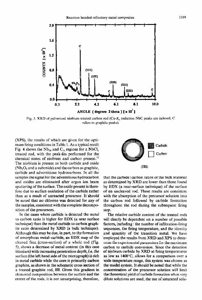
The XRD spectrum of the pulverized fired rods (Fig. 3) exhibit reflections due to the presence of graphitic carbon and the appropriate refractory- metal carbide. Oxides are only observed by XRD as a minor constituent for some of the samples (Fig. 3). It should be noted that the minimum firing temperature required for the detection of the metal carbide by XRD (see Table 1) is dependent on the identity of the metals. As is discussed below, sig- nificant quantities of the carbides are formed at lesser firing temperatures, but are presumably amorphous.
The surface chemical analysis of the fired rods was enabled by X-ray photoelectron spectroscopy
Reaction bonded refractory metal composites 1319
0.4
0.0 0.3 2.2 4.2 6.1 8.1 10.0
ANGLE ( degrees 2 theta ) [x 1O1]
Fig. 3. XRD of pulverized niobium treated carbon rod (Cu-K, radiation NbC peaks are indexed, C refers to graphite peaks).
(XPS), the results of which are given for the opti- mum firing conditions in Table 1. As a typical result Fig. 4 shows the Nbxd and Cl, regions for a NbCl, treated rod, with the peak-fits performed for the chemical states of niobium and carbon present.‘* The niobium is present as both carbide and oxide (Nb205 and a suboxide) and the carbon as graphite, carbide and adventitious hydrocarbons. In all the samples the signal for the adventitious hydrocarbon and oxides are eliminated after argon ion beam sputtering of the surface. The oxide present is there- fore due to surface oxidation of the carbide rather than as a result of unreacted precursor. It should be noted that no chlorine was detected for any of the samples, consistent with the complete decompo- sition of the precursors.
In the cases where carbide is detected the metal to carbon ratio is higher for EDX (a near surface technique) than the metal carbide to carbon graph- ite ratio determined by XRD (a bulk technique). Although this may be due, in part, to the formation of amorphous metal-carbide, an EDX map of the cleaved face, (cross-section) of a whole rod (Fig. 5) shows a decrease of metal content (in this case titanium) with increasing penetration depth, i.e. the surface (the left hand side of the micrograph) is-rich in metal carbide while the core is primarily carbon graphite, as shown in the schematic cross section of a treated graphite rod, III. Given this gradient in elemental composition between the surface and the centre of the rods, it is not unsurprising, therefore,
Carbide
Carbon
VW
that the carbide : carbon ratios of the bulk material as determined by XRD are lower than those found by EDX (a near-surface technique) of the surface of an uncleaved rod. These results are consistent with the absorption of the precursor solution into the carbon rod followed by carbide formation throughout the rod during the subsequent firing step.
The relative carbide content of the treated rods will clearly be dependent on a number of possible factors, including : the number of infiltration-firing sequences, the firing temperature, and the identity and quantity of the transition metal. We have employed the results from XRD and XPS to deter- mine the experimental parameters for the maximum carbon to carbide conversion. Since the detection of nipbium carbide by XRD at firing temperatures as low as 14OO”C, allows for a comparison over a wide temperature range, this system was chosen as the model system. It should be noted that while the concentration of the precursor solution will limit the theoretical yield of carbide formation when very dilute solutions are used, the use of saturated solu-

1320 (a) 4000
203.63 35.3 3d” carbide
206.36 26.5 3d3 carbide 207.02 15.9 3d5 peatoxide
r B 209.62 11.8 3d3 peatoxide
8
214.0
(b) 2000
Binding Energy (eV)
==W X Assignment
282.57 20.1 carbide 284.18 592 graphite 285.24 20.7 advmdtious hydrocarbon
Binding Energy (eV)
Fig. 4. (a) Nbxd and (b) C,, XPS spectra (monochromatized Al-K, radiation) of a surface. Peak positions are included (eV).
fired carbon rod
Fig. 5. Titanium EDX-map of a cross section of a single treated rod. The surface of the rod is at the far left of the picture with the centre at the far right.

Reaction bonded refractory metal composites 1321
0.16 -
g 0.14-
,
i 0.12 -
5 4 0.10 -
b 0.08 -
0.06! . I . I . I I 1
0 5 10 15 20 25
infiltration firing sequences (n)
Fig. 6. A plot of relative carbide content in the bulk of a niobium treated rod, as determined by XRD, vs number
of infiltration firing sequences (n).
tions (l-3 mol dmm3) in our experiments ensures that the precursor is not the limiting reagent.
In a typical series of experiments the carbon rods were subjected to a number (n) of infiltration-firing sequences (n = 1,5, 10,23) and then pulverized for XRD analysis. The results for the niobium treated rods are shown in Fig. 6. It can be seen that the bulk carbide content relative to residual graphite increases approximately two-fold between one and five cycles, and then remains essentially unchanged. This effect may be readily explained in terms of the SEM and EDX data (cf. Figs 2 and 4) which indicated that a dense composite is formed after firing. Thus, once sufficient reaction has occurred to produce a dense material within the surface layer of the rod, no further uptake of the precursor solution will occur due to pore-blocking, and as a consequence, no further bulk carbide formation results.
In order to investigate the effects of firing tem- peratures on carbide content a series of carbon rods were subjected to four soak-fire sequences over a range of temperatures, lOOO-3OOO”C, and the rela- tive carbide composition of the rods determined in the bulk and on the surface by XRD and XPS, respectively. The results for the formation of NbC as a convenient example, are presented in Fig. 7. In the case of niobium no crystalline carbide is formed below 1400°C. Between 1600 and 2400°C the quali- tative extent of carbide formation in bulk (as deter- mined by comparison of the relative intensity of the NbC and graphite peaks in the XRD) is significant and relatively constant; above 2400°C a further increase in the relative amount of carbide results. From the foregoing it is clear, therefore, that for the bulk material three distinct temperature regimes are present. The lowest range, below 14OO”C, does not result in crystalline carbide formation and may be related to the decomposition point of the precursor compounds (see below) which occurs between 1200
o.oT 1400 1800 2200 2600 3OOcl
Temperature ( “C)
Fig. 7. A plot of relative carbide content in the bulk and on the surface of a niobium treated rod, as determined by XRD and XPS respectively, vs the firing temperature.
and 1495°C; the former being the temperature at which chlorine is liberated from the oxychlorides, while the latter is the decomposition point of the least stable oxide of niobium, Nb205. Thus, carbide formation only occurs at temperatures above the decomposition point of the precursor materials. The constant bulk carbide formation between 1600 and 2400°C indicates that once the precursor decomposes carbide formation is essentially tem- perature independent. As such, the increase in the amount of carbide formations in the niobium sys- tems at temperatures above 2400°C may seem mis- placed. However, two factors may account for this, firstly, it should be noted that the melting point of niobium is 2470°C and the formation of carbide may be enhanced by the formation of a fluid state which allows for maximum diffusion and reactivity. Secondly, it has been previously observed that spon- taneous catalytic reaction occurs between carbon and niobium oxide above 25OO”C, and this may enhance the formation of carbide in the present system.13
As with the bulk carbide content the fraction of niobium carbide on the surface generally increases with increasing temperature (Fig. 7). However, below 1800°C no niobium carbide is observed on the surface ; all the niobium being present as oxide, and above 2600°C a small decrease in niobium car- bide content is observed. The decrease at high tem- peratures is consistent with the thermal decompo- sition (decarburization) and oxidation of the carbide at the firing temperatures.’ The lack of car- bide formation on the surface of the fired rod below 1800°C is not as easily explained but presumably it is due to the oxidation of the small amount of niobium on the surface. Thus, Fig. 7 indicates that the temperature range for maximization of carbide vs oxide vs carbon graphite both on the surface and the bulk of a niobium treated rod is 22OCL26OO”C.
Since we are primarily concerned with the max-

1322 A. N. MacINNES et al.
imization of carbide on the surface as opposed to bulk infiltration, we have investigated the surface carbide : carbon temperature profile for each of the metal precursor systems by XPS. The results for each element are briefly discussed below. The opti- mum firing temperature, that at which the car- bide : carbon ratio is a maximum, for each system was thus determined, and is given in Table 1. In addition, since the carbides all form a native oxide on their surface we have determined the tem- perature at which the elemental composition is max- imized for the metal. It should be noted that in some cases there is a significant difference between the optimum temperature determined from XPS and XRD. This disparity suggests that a balance exists between surface coverage and bulk penetration.
The titanium treated rods show a marked increase, from ca 20 to 30%, in the titanium content on the carbon surface at about 2000°C. This tem- perature is also the point at which the chemical identity of the titanium alters from oxide to carbide. However, at higher temperatures, 275O”C, the car- bide content again decreases, to ca 15%, consistent with decarburization. By contrast, the treated rods for the heavier group 4 metals, zirconium and hafnium, show a slow decrease in metal content at higher temperatures, possibly consistent with the loss of precursor by volatilization. Whereas, the XRD studies indicate carbide formation for both elements, the rods’ surface consists of entirely oxide, with no carbon being detected. The only exception is for zirconium at 2250°C where a small quantity (4.5%) of surface carbide is detected.
The vanadium treated samples show that while the vanadium content increases only moderately from 1500°C to 22OO”C, the carbide content increases, over the same temperature range, from zero to being the exclusive chemical species on the surface. However, at 2750°C there is no vanadium detected on the surface implying the complete vola- tilization of either the precursor and/or the resulting carbide or oxide has occurred.
As would be expected from the similarity in their chemistry the trends observed for niobium and tan- talum are related, both showing oxide at low tem- peratures, increasing carbide above 1800 and 1750°C for niobium and tantalum, respectively. Finally, in line with the XRD results a slight decrease in carbide content at high temperatures.
Although tungsten carbide (WC) was detected by XRD no carbide was observed on the surface of the treated rods by XPS over the range of 175&275O”C. However, no carbon was detected indicating that the surface is entirely oxide.14
Given that the oxidation protection of a carbon composite would require the formation, not only of
a carbide but a contiguous coating of oxide and/or carbide to inhibit oxidation of the substrate, then based on the above data we propose that our titanium, niobium and vanadium treatments are most suitable for the oxidation protection of porous carbon substrates. In order to determine the appli- cability of this carbide formation methodology for dense carbon substrates we have investigated the formation of NbC and TiC on carbon fibres and non-porous carbon graphite rods, respectively.” These studies are described below.
Non-porous carbon substrates
SEM-EDX studies on the porous rod (cf. Fig. 5) indicated that infiltration/carbide formation occurred at depths of ca 500-600 pm. Since the depth of penetration will be dependent on the den- sity and homogeneity of the carbon substrate we have treated a highly compacted (dense) bulk car- bon substrate (Union Carbide). The substrate was treated in an analogous manner to that described in Table 1 for the optimum TiC formation. Shown in Fig. 8 is the Ti EDX map of the cross section of a treated non-porous rod. It can be clearly seen that the average penetration depth, as indicated by the lighter area in the micrograph, is ca 15 pm. It should also be noted that deeper penetration has occurred in a number of areas, but this is most probably due to cracks (defects) in the surface, or areas of the rod that have been insufficiently compacted during processing.
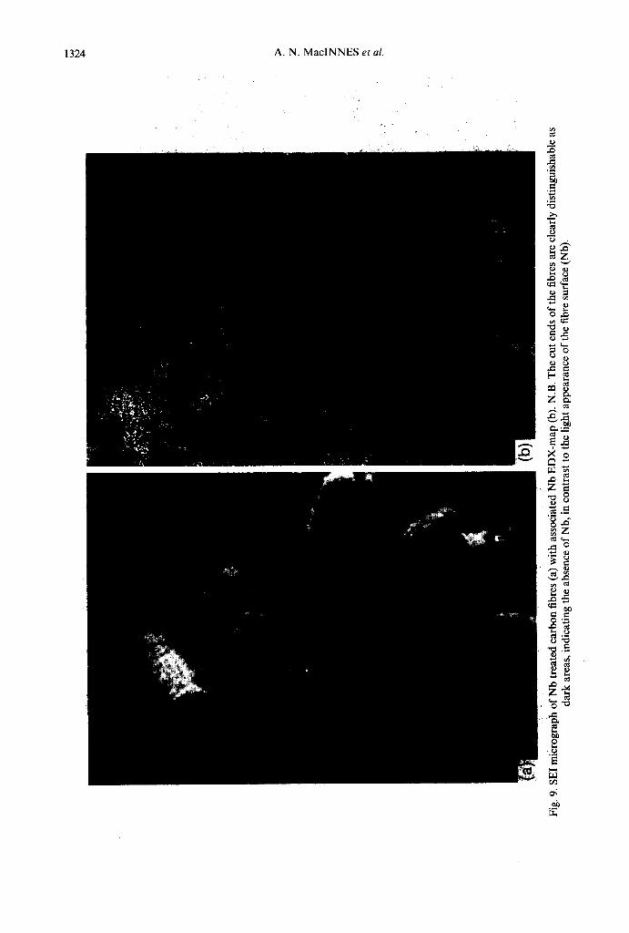
Carbon fibres represent perhaps the most dense form of graphitic materials, and as such should exhibit the lowest penetration during carbide for- mation. Carbon fibre tows were treated with an ethanolic solution of niobium pentachloride and subseq,uently fired in an analogous manner to that for the carbon rods described above. SEM micro- graphs of the fired tows show that although residual material (shown by EDX to be niobium rich) was formed between the fibres, the individual fibres are themselves coated (Fig. 9a) and may be readily sep- arated from any excess material by gentle teasing. The presence of niobium in these coatings is con- firmed by Nb EDX-mapping (Fig. 9b). The cut ends of the fibres are clearly distinguishable as dark areas, indicating the absence of Nb, in contrast to the light appearance of the fibre surface (Nb). The available data can, therefore, be interpreted by pro- posing that the firing sequence has, indeed, pro- duced a niobium carbide (and perhaps oxide) coat- ing on the fibres (as is evident from the increased diameter), 7 pm when compared to the untreated fibres 5 pm. The presence of a carbide coating on the individual fibre was confirmed by XPS and AES,

Reaction bonded refractory metal composites 1323
Fig. 8. Titanium EDX-mad of a cross section of a non-porous carbon rod. The surface of the rod (A) is indicated by the arrow.
as well as oxidation studies.” SEM of individual fibres show that the carbon fibre core remaining after treatment is approximately 2 pm in diameter. Thus the carbide coating is ca 2.5 pm in depth, significantly lower than for the other substrates dis- cussed.
Formation of Nb-Ti carbide solid solutions
While the reaction bonded process described above provides a convenient route to metal carbide coatings on carbon substrates, its chemical sim- plicity has the added potential that mixed carbide phases should be readily prepared by painting the substrate with solutions containing~more than one metal salt. Niobium carbide and titanium carbide are known to form solid-‘solutions,‘5 and as such represent a suitable system, for study of a mixed metal carbide coating ot&bbn substrates.
Porous carbon substrates were painted with etha- nolic solutions consisting of mixtures of NbCls and Tic&. The metal content of five solutions was con- trolled such that the niobium content was equal to 0, 25, 50, 75 and 100%. If the relative rates of formation of NbC and TiC are similar then the relative proportion of niobium should be retained from solution to the carbide compact. The carbon rods were fired at either 1800 or 2500°C to deter- mine the effect of firing temperature on mixed metal
solutions. The resulting relative metal (carbide and oxide) content was the-n determined by XPS analy- sis. The results of these runs are shown in Fig. 10. The formation of solid solutions, as opposed to separate NbC and TiC formation, was confirmed by XRD.
It can be seen that the relative niobium and titanium content of rods fired at 1800°C is within experimental error of the theoretical values based on the complete conversion of the metal compounds in the precursor solution. Thus, the metal content of the resulting carbide/graphite compact is controlled by the relative amounts of each precursor metal halide. In contrast, the analysis of rods fired at 2500°C are all titanium deficient. In fact the niobium content varies little compared to that of the precursor solution. The reason for the low titanium content cannot be due to thermal loss of the carbide (decarburization) since for the pure titanium system the optimum carbide content as determined by XPS is obtained by firing at temperatures between 2200 and 2500°C. Thus, the low titanium content must presumably be due to the preferential formation of NbC over Tic. If the rate of NbC formation at 2500°C is sufficiently greater than that of TiC then the available carbon substrate will be consumed by the formation of NbC, and further heating will only cause evaporation of the titanium precursor, lead- ing to a niobium rich composite.
? ?
;
Fig.
9.
SE1
mic
rogr
aph
of N
b tr
eate
d ca
rbon
fi
bres
(a)
with
ass
ocia
ted
Nb
ED
X-m
ap
(b).
N.B
. T
he c
ut e
nds
of t
he f
ibre
s ar
e cl
earl
y di
stin
guis
habl
e as
da
rk
area
s, i
ndic
atin
g th
e ab
senc
e of
Nb,
in
cont
rast
to
the
lig
ht a
ppea
ranc
e of
the
fib
re s
urfa
ce (
Nb)
.

Reaction bonded refractory metal composites 1325
0.2 0.4 0.6 0.8
Solution Nb content (96)
Fig. 10. A plot of the relative niobium and titanium content (% Nb) of rods fired at 1800 and 2500°C as a function of the precursor solution composition (% Nb). The dashed line represents the theoretical values based
on the precursor solution.
Decomposition of the inorganic precursors
All of the halide salts used as precursors are vol- atile at the firing temperatures employed for carbide formation. It is clear, therefore, that the metal hal- ides cannot themselves be involved in the carbide forming reaction. In fact, none of the halides, MCI,, retain their chemical identity in moist alcoholic solutions ; each reacts with the water present in the solvent to liberate HCl gas and form solvated oxides and oxide chlorides.‘6
Titanium trichloride has been reported to react with water, in the air, to give titanic acid which in the presence of the HCl liberated yields blue solutions of titanium oxydichloride (eq. 1).17
TiCl,+H*O -H,Ti03-----+ TiOCl* (1)
While zirconium and hafnium tetrachloride have both been shown to form the analogous oxy- chlorides directly upon hydrolysis (eq. 2).”
MCl,(M = Zr,Hf)+H20- MOCl* + 2 HCl
(2)
The presence of signals due to [MOClJ+ and [MOCl]+ in the FAB mass spectrum of the ethanolic precursor solutions confirms the identity of the metal containing species to be the oxydichlorides of Ti, Zr and Hf.
Unlike Ti, Zr and Hf the ethanolic hydrolysis of V, Nb and Ta chlorides results in a complex mixture of species. Vanadium trichloride, VC&, is known to readily dissolve in both water and alcohols, ROH, to form the solvated complexes (eq. 3 and 4).19
VCl,H’O IVCl,(H,O)JCl (3)
VC13 = pCl,(ROH),]Cl (4)
Although these chloride salts are moderately stable,
oxidation may occur, resulting in the formation of a variety of oxide and oxychloride salts, e.g. VOC153- which is commonly prepared by the interaction of ethanolic HCl with V205.‘6
The ethanolic hydrolysis of niobium and tan- talum pentahalides has been reported to result in the formation of the oxychlorides MOC13 and MOrCl as well as the oxides M20S.Z0’21 FAB mass spectra of the niobium and tantalum precursor solu- tions indicates the presence of both M-O and M- Cl fragments, while the 93Nb NMR spectra is con- sistent with the formation of solvated oxide-chlor- ide species.
Since the WC16 and the oxychlorides, W02C12 and WOCL,, are all volatile under the conditions employed for carbide formation it is unlikely that these are the direct precursors to the metal carbide. Tungsten hexachloride readily dissolves in dry etha- nol to form a deep blue solution, however, in the presence of excess water hydrolysis occurs resulting in the formation of tungstic acid (eq. 5).
WCl,+5H,O- WOj*2Hz0+6HCl (5)
In the present case complete hydrolysis does not occur since FAB Mass Spectral data indicates that tungsten-chloride bonds are retained since peaks due to lWClJ+ are observed as the major tungsten containing fragments along with mod’. As with the group 5 metals it is probable that the tungsten precursor solution consists of a mixture of oxide and oxide-chloride species, possibly including w2C1604]2- which has been recently isolated.16
Thus, based on literature precedent, and our qualitative spectroscopic and analytical studies we propose that the precursor solutions consist of sol- vated metal oxide<hlorides and/or oxides. Ther- mogravimetric analysis indicates that while the “free” solvent boils at 69°C ethanol remains coor- dinated until ca 140°C above which no significant mass loss occurs below 800°C. Elemental chemical analysis of the residue indicates the presence of only oxygen, chlorine and the appropriate metal, i.e. insufficient carbon is present to account for the formation of carbide from the direct decomposition of the metal precursor compound. Thus the carbide carbon must originate from the graphite rod not the precursor solution.
Although no direct decomposition of the pre- cursor is observed on heating to 800°C (the drying temperature employed in the carbide formation process), in the presence of carbon graphite a small quantity of phosgene gas, 0=CC12, is evolved22 as a result of the reduction of the metal compound by the carbon (e.g. eq. 6).
TiOC12 + 2C - A TiC+O=CCl, (6)
1326 A. N. MacINNES et al.
The quantity of phosgene detected increases on heating the precursor soaked graphite rods at the firing temperatures required for carbide formation. In addition to the presence of phosgene, analysis of the evolved gases indicates the liberation of sig- nificant quantities of chlorine gas, possibly as a result of the thermal decomposition of the metal oxychlorides, e.g. eq. 7.
TiOClz n TiO + Cl2 (7)
The firing step would thus result in the formation of a metal suboxide and the elimination of chlorine. It should be noted that no chlorine is detected in the treated rods. The suboxide produced would then subsequently be reduced by the carbon, e.g. eq. 8.
TiO+2CB TiC+CO (8)
CONCLUSION
A new simple to apply chemical route for the formation of refractory metal carbide coatings has been developed for carbon graphite substrates, in which the carbon substrates act as a sacrificial pre- form for the formation of surface carbide. We term the process the formation of a “reaction bonded” carbide coating, because of the chemical synthesis of a graded interface between the carbide and the carbon substrate. As expected the depth of pene- tration/carbide formation is highly dependent on the density of the carbon substrate. However, we note that continuous coatings are formed even on carbon fibre substrates. The decomposition of the oxychloride precursors provides in situ activation for the carbon substrate, which lends itself to the rapid treatment of carbon materials, in particular fibre tows. Controlled homogeneous solid solutions of titanium and niobium carbides are readily pre- pared by the use of a suitable mixed precursor solu- tion. However, the firing temperature is found to be a controlling factor in the composition of the mixed carbide composites.
We believe that our infiltration/firing process rep- resents a simple chemical method of providing a carbide layer on graphitic performs for increased oxidation resistance. We envisage that this reaction bonded coating may be used by itself or as a com- ponent of a multilayer system.
EXPERIMENTAL
Tic&, ZrCl.,, HfC&, VC!&, NbC&, TaCl, and WC& were used as supplied (Strem Chemicals, Newburyport, MA) without further purification. Carbon rods, 4 mm diameter, type MD (Bay Car-
bon) and high-density (Union Carbide). Carbon fibre tows: IM7, unsized, 5-,um diameter, 12,000 fibres/tow (Hercules, Inc.) and Fortafil 3(C)unt (Akzo Chemicals) were all used as received. Ethanol was used as purchased.
Precursor analysis was enabled by multinuclear NMR, FAB-Mass Spectroscopy and thermo- gravimetric/differential thermal analysis (TG/ DTA). NMR spectra were recorded on Bruker AM-400 (‘H, CDCl,) and Bruker WM-300 (93Nb, EtOH). FAB-Mass spectra were obtained by using a JEOL instrument with glycerol as the solvent matrix. Thermogravimetric/differential thermal analyses were obtained on a Seiko 200 TG/DTA instrument, using predried argon as the carrier gas. Analyses for chlorine and phosgene were carried out using chemical specific spot tests.** The treated rods, fibres and carbon substrates were char- acterized by X-ray photoelectron spectroscopy (XPS), powder X-ray diffraction (XRD) and scan- ning electron microscopy (SEM). XPS spectra were collected on a Surface Science Instruments Spec- trometer (Model SSX-100) with a mono- chromatized Al-K, source. The spectra were acquired with 50 eV pass energy and a 101) pm spot size. Radiation damage was insignificant over the acquisition times used. All spectra were calibrated to the gold AuAf peak at 84 f 0.1 eV. XRD data of the pulverized rods was collected using a Philips powder diffractometer. SEM studies were per- formed on JEOL JSM-35 and 6400 scanning micro- scopes.
Preparation of carbide composites
In a representative experiment TiC13 (ca 6 mmol) was slowly added to EtOH (ca 4 cm’) in air. CAU- TION: The reaction is highly exothermic and lib- erates HCl gas. The resulting solution was allowed to evaporate until viscous (ca 2 cm3). A 70 mm length of 4 mm diameter carbon rod was either soaked in (30 s), or painted with, the ethanolic solu- tion and then air dried. The treated rod was then resistively heated under an argon blanket, in the apparatus shown in Fig. 1. Firing was performed in three stages. Two drying stages at ca 200°C and 700-8OO”C, for 30 s each, to remove all volatiles associated with the precursor solution, followed by a final high temperature reactive fire for a total of 5 s at 135&22OO”C, to form the metal carbide. The firing temperatures were determined by optical pyrometry, and there was no induction time in the heating process.
The carbon fibre tows were immersed, or painted, with the metal chloride solution and fixed between

Reaction bonded refractory
the electrodes (cf. Fig. 1). Note that the metal-con- taining solutions readily wet and spread throughout the fibre tow, thus requiring no separation of the
tow for complete fibre coverage.
Acknowledgement-Support for A.R.B. provided by the Office of Naval Research, the Aluminum Research Board, and Alcoa (in the form of a Directors Fellowship). Support for T.G. provided by Northeastern University in the form of a Barnett Innovative Research Award. We are grateful to Drs A. M. Blough and J. Hessling (Hercules, Inc.) and F. Via (Azko, Inc.) for the donation of carbon fibres.
1 See for example : (a) L. R. McCreight, H. W. Rauch, Sr and W. H. Sutton, Ceramic and Graphite Fibres
and Wiskers, A Survey of Technology. Academic Press, New York (1965); (b) P. Bracke, H. Schumans and J. Verhoest, Inorganic Fibres and Composite
Materials. A Survey of Recent Developments. Per- gamon Press, Oxford (1984) ; (c) H. G. Sowman and D. D. Johnson, Ceram. Eng. Sci. Proc. 1985,6,1221;
(d) B. Marauyama, F. S. Ohuchi and L. Rabenbergy, J. Mater. Sci. 1990,9, 864. J. R. Strife and J. E. Sheehan, Ceram. Bull. 1988,67,
369.
5.
W. Chou, A. Kelly and A. Okura, Composites 1985,
16, 187, and references therein. M. M. Donovan, J. M. MacLaren, M. E. Eberhart and A. R. Barron, Mat. Res. Sot., Symp. Proc. 1990, 193, 149. P. D. Stupik, P. E. Laibinis and A. R. Barron, Indu-
stry-University Advanced Materials Conf IZ, p. 398. AMI, CO (1989).
6. P. D. Stupik, T. R. Jervis, M. Nastasi, M. M. Dono-
REFERENCES
7.
8.
9.
10.
11.
12.
13.
14.
15.
16.
17. 18.
19.
20.
21.
22.
metal composites 1327
van and A. R. Barron, Mat. Res. Sot., Symp. Proc.
1990,170, 155. P. D. Stupik, M. M. Donovan, A. R. Barron, T. R. Jervis and M. Nastasi, Thin Solid Films 1992, 207, 138. A. R. Barron, A. N. MacInnes and T. G. Gilbert, U.S. Patent 1993, 5238711. A. N. MacInnes, A. R. Barron, R. S. Soman and T. R. Gilbert, J. Am. Ceram. Sot. 1990,73, 3696. A. N. MacInnes, J. Li, T. R. Gilbert and A. R. Barron, Mat. Res. Sot., (extended abstracts) 1990, 23, 49.
A. N. MacInnes, A. R. Barron, J. Li and T. R. Gilbert, J. Am. Ceram. Sot. 1991,74,2928.
C. D. Wagner, L. H. Gale and R. H. Richmond, Anal. Chem. 1979,51,466. (a) H. C. Yi and J. J. Moore, J. Mater. Sci. 1990, 25, 1159 ; (b) J. B. Holt and Z. A. Munir, J. Mater. Sci.
1986, 21, 251.
A. Proctor and P. M. A. Sherwood, Anal. Chem. 1982,54, 13. P. Schwarzkopf and R. Kieffer, in Refractory Hard
Metals. MacMillan Company, New York (1953). F. A. Cotton and G. Wilkinson, Advanced Inorganic
Chemistry, 4th edn, pp. 71&719. Wiley, New York (1980). J. J. Ebelmen, J. Pharm. Chim. 1946,12,437.
A. Rosenheim and P. Frank, Chem. Ber. 1907, 40, 803.
Y. Doi and M. Tsutsui, J. Am. Chem. Sot. 1978,100, 324.
R. F. Weinland and L. Storz, Z. Anorg. Allgen.
Chem. 1907,54,223.
H. Schiifer and F. Kahlenberg, Z. Anorg. Allgen. Chem. 1960,305,339. F. Feigl, Spot Tests, Volume II Organic Applications.
p. 179. Elsevier, New York (1954).