rcar low-speed structural crash test protocol...rcar low-speed structural crash test protocol 7 / 18...
TRANSCRIPT

RCAR Low-speed structural crash test protocol
Issue 2.3
October 2017

RCAR Low-speed structural crash test protocol
2 / 18 Issue 2.3
EDIT 10/2017:
General: clear specification of tolerances for test speed
“6.3 Door” added
“6.6 Vehicle Underbody Measurement” moved from 8.0 (becoming mandatory)
“Propelling Vehicle rearwards to Barrier” deleted from 8.0 (omitted)

RCAR Low-speed structural crash test protocol
3 / 18 Issue 2.3
INDEX 1.0 INTRODUCTION 2.0 SCOPE 3.0 DEFINITIONS 4.0 TEST FACILITY AND TEST VEHICLE PREPARATION - FRONT IMPACT 5.0 TEST FACILITY AND TEST VEHICLE PREPARATION - REAR IMPACT 6.0 INSPECTIONS 7.0 TEST REPORT GUIDELINES 8.0 OPTIONAL MEASUREMENTS AND OBSERVATIONS APPENDIX 1: Barrier drawings and description: Front Impact APPENDIX 2: Mobile barrier drawings and description: Rear Impact APPENDIX 3: Panel gap measurement guide APPENDIX 4: Underbody measurement guide APPENDIX 5: Damage percentage guide

RCAR Low-speed structural crash test protocol
4 / 18 Issue 2.3
1.0 INTRODUCTION
This document describes the RCAR test procedure to assess a vehicle’s damageability and repairability. The assessment includes an estimation of the vehicle damage (physical damage and repair cost) in two impacts: A 15 km/h frontal impact into a rigid barrier and a rigid-faced mobile barrier striking the rear of the stationary vehicle at 15 km/h.
2.0 SCOPE
Improving passenger vehicle damageability and reparability has been an important RCAR topic since the Council was established in 1972. Towards this end RCAR implemented two 15 km/h, 40% overlap crash tests in order to encourage vehicle designers to limit unnecessary damage to the structure of passenger vehicles in low speed front and rear crashes. The test procedure was revised in 2006 to change the impact angle from 0° to 10° and the rear impact mobile barrier weight from 1000 to 1400kg. In addition to this test procedure, RCAR implemented a lower speed (10 & 5 km/h) bumper test in 2010 which encourages vehicle manufacturers to produce bumper systems that feature tall energy absorbing beams and crash boxes that are fitted at common height; both of which can effectively protect the vehicle in low speed crashes. The following procedure applies to power driven passenger vehicles with a weight of 3,500 kilograms or less (Euro M1 category). Other vehicles may be similarly treated if required by the manufacturer or the test facility.

RCAR Low-speed structural crash test protocol
5 / 18 Issue 2.3
3.0 DEFINITIONS
Active Head Restraints Head restraints whose position changes (typically moving closer to the occupant’s head) by a triggering mechanism and motive force (springs, pyrotechnics, etc.) when a crash is detected to reduce whiplash injury risk. Airbag (Supplementary Restraint System) A device used as a supplement with seat belts designed to inflate rapidly during an
automobile collision, preventing the vehicle occupants from striking interior objects such as
the steering wheel, instrument panel, etc. Barrier A rigid, steel contoured barrier described in Appendix 1. Belt Crash Tensioner A mechanism affixed to the seatbelt system to remove excess slack from the seat belt webbing via springs or pyrotechnics when a crash is detected. Curb Weight The weight of the unoccupied vehicle, in running order, prior to test preparation. The curb weight of the vehicle includes a full fuel tank (per vehicle manufacturer specification), spare tire and any tools supplied as standard equipment by the vehicle manufacturer. Mobile Barrier A rigid barrier attached to the front of a rolling cart, resulting in a total weight of 1400 kg ±5 kg, described in Appendix 2. The barrier dimensions are fixed, the remaining cart dimensions are discretionary. Overlap/Offset Percent of the vehicle width as measured at the wheel wells (including moldings and sheet metal protrusions) at the corresponding axle — front axle for the front test and rear axle for the rear test. Vehicle Width The width of the test vehicle’s body, including rigid moldings and sheet metal protrusions, but not including mirrors, lamps, tire pressure indicators, etc. This is usually, but not always, located at the front or rear wheel arch.

RCAR Low-speed structural crash test protocol
6 / 18 Issue 2.3
4.0 TEST FACILITY AND TEST VEHICLE PREPARATION - FRONT IMPACT
4.1 Test facility
The test area shall be large enough to accommodate the acceleration track, barrier and technical installations necessary for the test. The final 5 meters of track adjacent to the barrier shall be horizontal, flat and smooth.
4.2 Barrier set up and position
The barrier’s dimensions shall conform to those shown in Appendix 1. The barrier may be secured to a rigid weight or anchored directly to the floor in such a way that it cannot move during impact. In either case, the front face of the barrier should be vertical to within ±1°. The barrier shall be oriented with its front face 10° (±1°) relative to the perpendicular of the longitudinal axis of the test vehicle. Initial vehicle contact will be on the steering column side and the front of the vehicle shall overlap the face of the barrier by 40% ± 25 mm. The overlap is measured at initial impact by projecting the edge of the barrier in the vehicle’s longitudinal axis onto the test vehicle front end (see Appendix 1).
4.3 Test vehicle set up
The test vehicle shall be inspected for previous damage prior to test setup and be representative of the production model (usually the most popularly equipped). At the discretion of the test facility and/or vehicle manufacturer, select components may be replaced by equivalent masses where the substitution will have no effect on the results. The test vehicle fuel tank shall be full, or at the discretion of the test facility, drained and refilled using a fuel substitute to within 5% of the manufacturer’s specification. Alternatively, equivalent ballast may be positioned and secured near the empty fuel tank. All other fluids (oil, coolant, etc.) may be drained, however, their weight should be supplemented with ballast to achieve the required test mass. It is recommended that the air conditioning system be evacuated and pressure checked for leaks after the test. The tires should be inflated to the
manufacturer’s recommended pressure for single occupant loading and low speed conditions.
4.3.1 Vehicle test weight
The vehicle test weight is the curb weight plus a 75 5 kg test dummy or equivalent ballast on the driver’s seat secured with the standard 3-point seat belt. If this weight cannot be achieved for any reason, the vehicle may be tested at a lower weight with the mutual agreement of the vehicle manufacturer and the test facility. This agreement must be included in the test report. The weight of any on-board test equipment shall be offset by removing ballast or components which have no effect on the test results. The resulting change in weight caused by the addition of ballast or on-board test equipment, or the removal of components, shall not change the vehicles front-to-rear weight ratio by more than 5%. By mutual agreement between the vehicle manufacturer and the test facility, the vehicle may be tested at a weight higher than the determined test weight. This agreement must be included in the test report along with the final test weight of the vehicle.

RCAR Low-speed structural crash test protocol
7 / 18 Issue 2.3
4.3.2 Vehicle test condition
If adjustable, the brake and accelerator pedals, seat belt anchor points and steering column shall be placed at the midpoint of their travel range or the nearest position to midpoint. The front seats shall be set at the midpoint of their travel range, both laterally and vertically. The seatback shall be set to a typical driving position or to the position specified by the manufacturer. Alternately, a 23° manikin torso angle can be used (as measured by the SAE J826 H-Point manikin). The head restraints shall be set at the upmost of their adjustment range. The vehicle windows can be either open or closed, per the test facility’s requirements. The ignition switch should be turned to the ‘on’ position, with all safety equipment (seat belt crash tensioners, airbags, etc.) in operation. The airbag indicator light in the instrument panel shall be observed long enough to establish that the system is in working order when the ignition is switched “on” (the engine should not be running except where it is used to propel the test vehicle). The transmission should be in the neutral position with the parking/hand brake fully released. All doors shall be closed and either locked or unlocked, per the test facility’s requirements. If equipped, sun/moon roofs will be closed and soft/convertible tops be in the ‘up’ position. 4.3.3 Propulsion of test vehicle
The test vehicle may be propelled by its own engine or by another acceptable propelling force. The test facility shall ensure drive systems or vehicle speed controls do not influence the test condition. At the moment of impact the vehicle shall be free of relevant exterior or propelling forces. To stabilize the approach some drag may be allowed (e.g. using hand brake). The impact velocity should be 15 km/h (tolerance +1/-0 km/h) measured not more than 1 meter before contact with the barrier.

RCAR Low-speed structural crash test protocol
8 / 18 Issue 2.3
5.0 TEST FACILITY AND TEST VEHICLE PREPARATION - REAR IMPACT
The test facility and preparation of the test vehicle shall be similar to that described for the front impact (section 4.1 and 4.3), with the following additions/exceptions: 5.1 Barrier set up and position The mobile barrier shall conform to the dimensions shown as “fixed” on the drawing in Appendix 2 (the remaining dimensions are discretionary). At initial impact the front face of the barrier should be vertical to within ±1°. The axles shall be accurately aligned and secured to ensure the mobile barrier follows a straight course. The mobile barrier shall be equipped with brakes and/or restrained in such a way that after initial vehicle contact no additional unintentional impact takes place. The mobile barrier shall be propelled in accordance with 4.3.3 and have a weight of 1400 kg ±5 kg. The vehicle test position shall ensure that the mobile barrier overlaps the rear of the test vehicle by 40% ± 25 mm and that its longitudinal axis forms a 10º (±1°) angle with the longitudinal axis of test vehicle. The overlap is measured at the point of initial impact by projecting the inboard edge of the barrier in the mobile barrier’s longitudinal axis onto the test vehicle rear end (see Appendix 2).
5.2 Test vehicle set up
The test vehicle shall comply with section 4.3; however, if the vehicle was used for the front impact, it is for the vehicle manufacturer and/or the test facility to determine that it is able to withstand an additional impact. After a thorough inspection of the vehicle, the test facility and/or manufacturer will verify that the damage sustained during the front impact will have no adverse effect on the results of the rear impact. The test vehicle will be positioned in the test area so that the mobile barrier will contact the rear of the vehicle on the appropriate side as determined by the manufacturer and/or test facility. Normally this will be the side opposite that which was impacted during the front test, unless there is evidence to show that the opposite side is more appropriate. Note: Because the vehicle is in neutral at time of impact, a braking mechanism may be required to control unwanted vehicle movement after the impact.
5.3 Propulsion of Mobile Barrier
The mobile barrier can be propelled by any acceptable propelling force. At initial impact the barrier shall be free of relevant exterior or propelling forces (to stabilize the approach some drag may be allowed, e.g. using hand brake). The impact velocity should be 15 km/h (tolerance +1/-0 km/h), measured not more than 1 meter before contact with the vehicle.

RCAR Low-speed structural crash test protocol
9 / 18 Issue 2.3
6.0 INSPECTIONS
6.1 Instrumentation Additional instrumentation (accelerometers, etc.) may be installed on the test vehicle at locations agreed upon by the test facility and/or manufacturer. 6.2 Photography The test vehicle shall be photographed extensively before and after each test with the images being included with the test report. 6.3 Door After the front test, the front door on the impacted side shall be opened completely. The resulting damage shall be considered for the rating. 6.4 Safety system inspections The vehicle safety systems shall be inspected after each test. The condition of the airbag(s), seat belt crash tensioners and active head restraints will be recorded in the final report. 6.5 Vehicle wheel alignment The vehicle shall have a four-wheel alignment/geometry check before and after each impact. Any suitable measuring equipment may be used, provided it records all relevant geometric figures and the equipment produces a permanent record of the data.
6.6 Vehicle Underbody and Panel Measurement To determine vehicle deformation, external panel gap and underbody measurements shall be taken before and after each impact at locations agreed upon by the test facility/manufacturer (see suggested forms in Appendices 3 and 4). Any suitable measuring equipment may be utilized, providing the same reference points are used each time and the equipment produces a permanent record of the data. Other measurements may be taken with the agreement of the test facility and the manufacturer.

RCAR Low-speed structural crash test protocol
10 / 18 Issue 2.3
7.0 TEST REPORT GUIDELINES
It is suggested that the test report contain, at a minimum, the following information:
7.1 Vehicle
- The vehicle identification number (VIN) and the make, model and trim level, if applicable.
- The front and/or rear vehicle width and the corresponding impact offset distance from vehicle centerline (see Appendices 1 and 2)
- The vehicles curb and test weight. Separately list the weight of the dummy/ballast and on-board equipment. Record the front-to-rear weight ratios at both curb and final test weight.
- Detailed descriptions and photographs of any previous damage that will not affect the outcome of the test.
- Vehicle tire pressure.
- Wheel alignment data.
7.2 Test facility
- The complete test facility name, address and identification number (if any) along with
the date and time of impact.
7.2 Test results
- Measured vehicle (or barrier) speed at impact.
- The condition of vehicle safety systems (deployed airbags, airbag fault lights, activated head restraints, etc.)
- Measured overlap/offset from the vehicle centerline (Appendix 1 & 2), and the actual impact overlap/offset.
- Test damage reports (estimates), including parts prices, labor hours, paint and materials required to repair the vehicle to ‘like new’ condition. Estimate must contain a detailed list of parts damaged and indicate whether the parts are to be repaired or replaced.
- Each damaged part (body panel, bumper cover, reinforcement, radiator support, etc.) shall be inspected and photographed extensively.
- Signature of the senior engineer responsible for the test.
- All optional measures recorded during test preparation vs. post test (panel gap, underbody, etc.).
7.3 Optional items
- Transducer location charts (front and rear).
- High speed film specification chart for each camera.

RCAR Low-speed structural crash test protocol
11 / 18 Issue 2.3
8.0 OPTIONAL MEASUREMENTS AND OBSERVATIONS
- In addition to photographs, the estimated percentage of damage to each part may be
recorded to aid in comparing vehicle damage between different markets (see Appendix 5).
- The tests may be recorded digitally, on video tape and/or film. Where high speed film is used, the cameras should be set to the vehicle manufacturer’s or test facility’s requirements (usually 500 – 1000 FPS).
- The test vehicle exterior may be painted using non-reflective material to provide quality high speed film footage. Underbody components may also be painted in contrasting colors to distinguish them from each other.
- The test vehicle may be marked up as required to provide reference points for high speed film analysis. The target markers shall be placed at 200 mm intervals along the length of the vehicle and on other important areas, in accordance with the vehicle manufacturer’s or test facility’s requirements. Door openings may be marked in such a way that any movement during the impact can be detected post impact.
- The test procedure may also be conducted using a pendulum; however, the device shall be capable of achieving the same results had the test been run utilizing a barrier. The test report shall record the pendulum weight and the calculation to determine the pendulum height required to reach the 15 km/h (tolerance +1/-0 km/h) impact speed. Additionally, provision shall be made to restrain the test vehicle immediately following the impacts.
- Instrumented test dummies may be used for the purposes of determining injury data.

RCAR Low-speed structural crash test protocol
12 / 18 Issue 2.3
At the moment of impact the vehicle shall be free of the vehicle propulsion system. Test vehicle weight = curb weight with full fuel tank + additional test devices and 75 kg ballast for driver
Key: U = 40% Overlap B = Vehicle width (front) R = 150 mm Radius F = Test vehicle A = 10 Degree Angle
The height of the barrier shall exceed the height of the front of the test vehicle
Appendix 1 Barrier Drawings and Description: Front Impact

RCAR Low-speed structural crash test protocol
13 / 18 Issue 2.3
Appendix 2
Mobile Barrier Drawings and Description: Rear Impact
Key: MB = Mobile Barrier H = Barrier height
(700mm+/-10 mm) h = Ground clearance
(200 mm +/- 10 mm) F = Test vehicle R = Constant radius (150 mm) r = Constant radius (50 mm) U = 40% Overlap B = Vehicle width (rear)

RCAR Low-speed structural crash test protocol
14 / 18 Issue 2.3

RCAR Low-speed structural crash test protocol
15 / 18 Issue 2.3
Appendix 3 Panel Gap Measurement Guide
The following table may be used to record gap measures, in mm, before and after the impact. The reference points are shown in the figure below. Separate forms should be used for front and rear impacts.
Test ID: Date:
Before After Diff. Before After Diff.
Hood/Bonnet 24
1 25
2 26
3 27
4 28
5 29
6 Rear Door L
7 30
8 31
Sun Roof 32
9 33
10 34
11 35
12 Rear Door R
13 30
14 31
15 32
16 33
Front Door L 34
20 35
21 Trunk/Boot
22 40
23 41
24 42
25 43
26 44
27 45
28 46
29 47
Front Door R 48
20 49
21 50
22 51
23

RCAR Low-speed structural crash test protocol
16 / 18 Issue 2.3
RCAR Low-speed structural crash test protocol
17 / 18 Issue 2.3
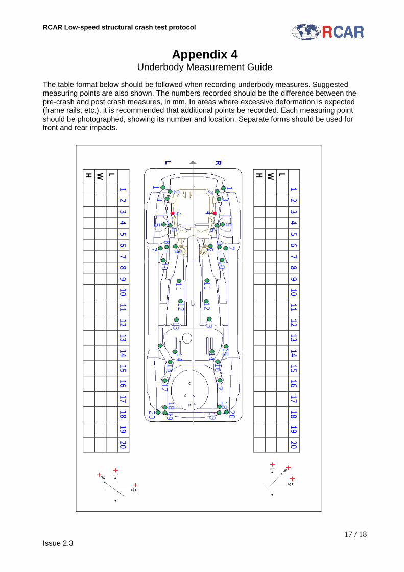
Appendix 4 Underbody Measurement Guide
The table format below should be followed when recording underbody measures. Suggested measuring points are also shown. The numbers recorded should be the difference between the pre-crash and post crash measures, in mm. In areas where excessive deformation is expected (frame rails, etc.), it is recommended that additional points be recorded. Each measuring point should be photographed, showing its number and location. Separate forms should be used for front and rear impacts.
1
2 3
4 5
6 7
8 9
10 11
12 13
14 15
16 17
18 19
20
L
W
H
1
2 3
4 5
6 7
8 9
10 11
12 13
14 15
16 17
18 19
20
L
W
H

RCAR Low-speed structural crash test protocol
18 / 18 Issue 2.3
Appendix 5 Damage percentage guide
The photographs below illustrate one technique that can be utilized to estimate the damage to a vehicle hood. By dividing the panel into quarters it is easier to estimate the damaged area. When panels such as hoods, fenders and doors have internal bracing, the damage to the bracing should be added to the exposed portion. The example hood below has approximately 20% of the top surface damaged and 10% of the underside damaged. The total estimated damage to this hood is 30%.