rcaf mustang mk.i addendum article/aircraft/mustang... · green/sky gray, dupont’s...
TRANSCRIPT
- RCAF Mustang Mk.I Addendum - A selection of articles from past issues of RT to go
with Mustang articles in RT 32/3
ipmscanada.com
Mustang Addendum (June 2013) Contents• Page 3 - Mustang I Profiles, RT 32/3
• Page 5 - Mustang I Article, by Bruce Archer, RT 32/3
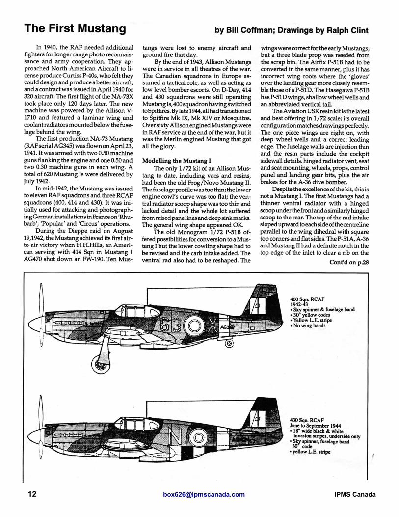
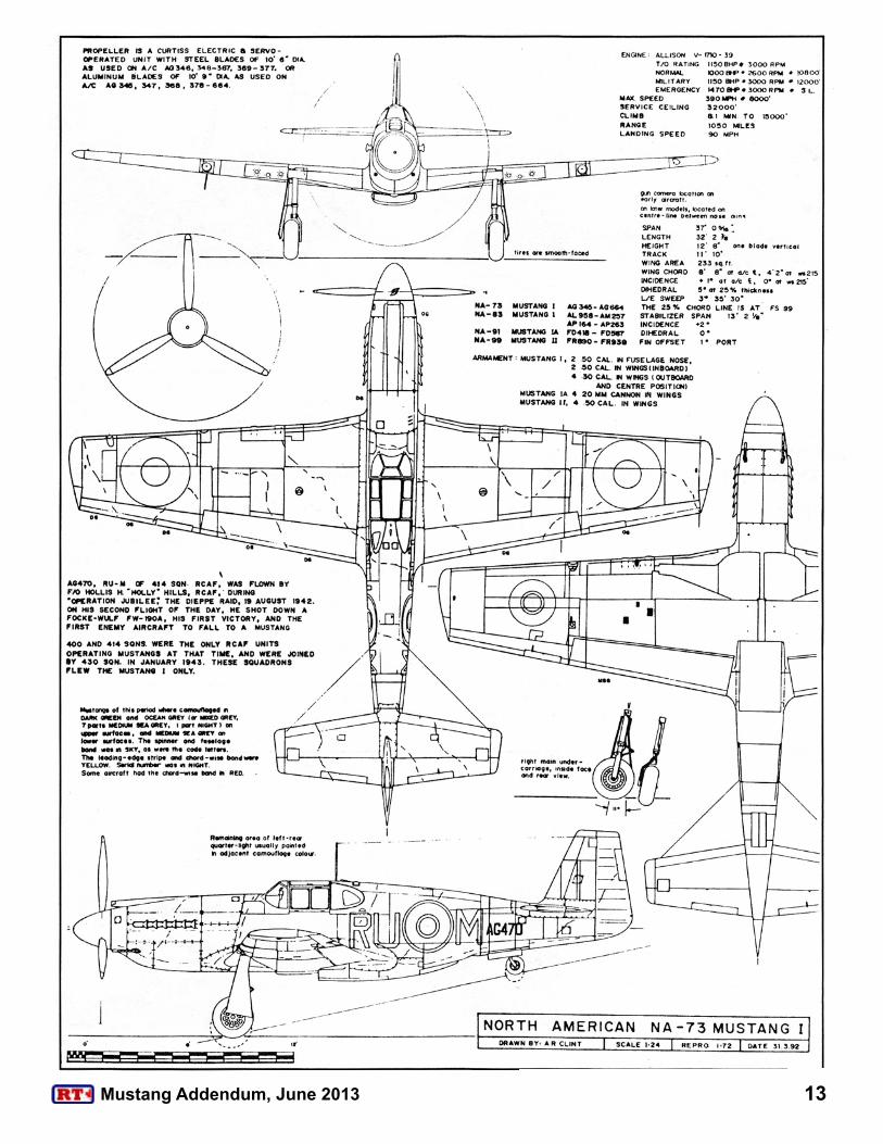
• Page 12 - The First Mustang, by Bill Coffman, RT 24/1
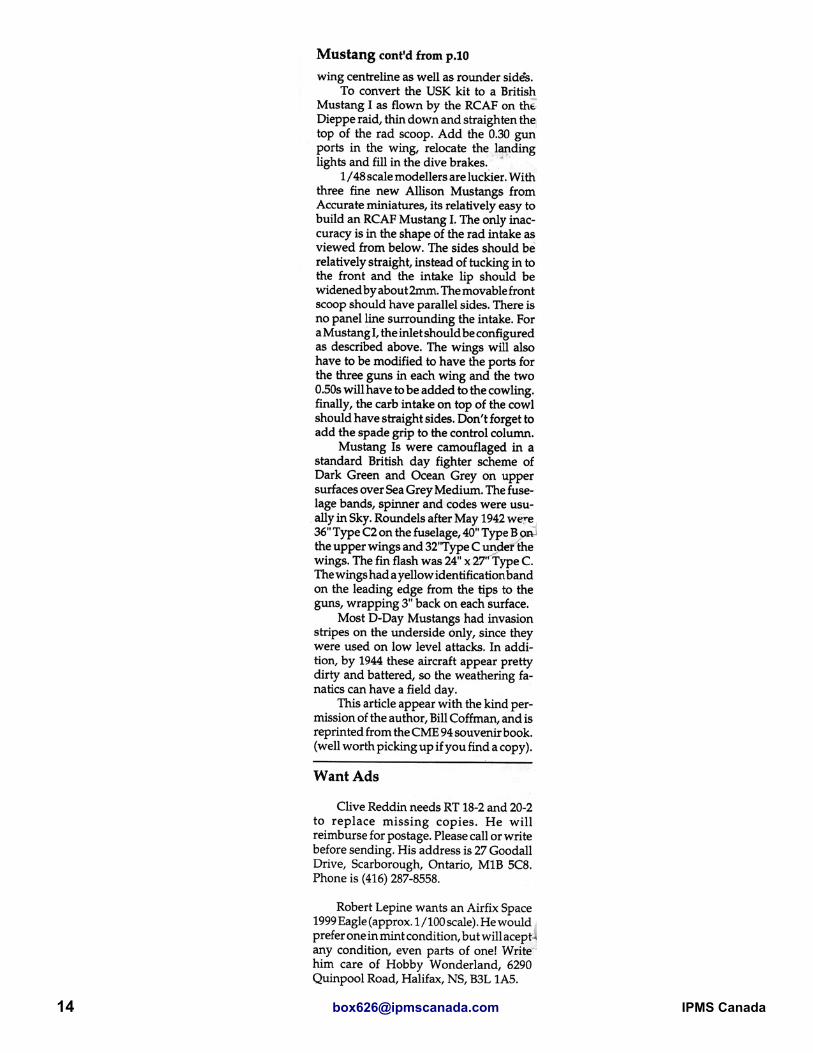
• Page 15 - Mustang I AM251/O, 414 Squadron, by Steve Sauvé, RT 24/1
• Page 21 - North American Mustang I, by Cam Harris, RT 24/3
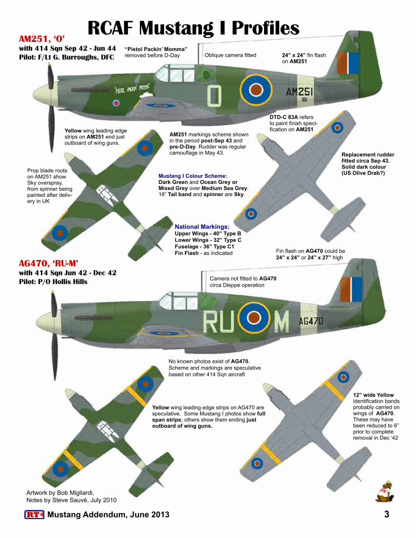
Artwork by Bob Migliardi, Notes by Steve Sauvé, July 2010
RCAF Mustang I Profiles“Pistol Packin’ Momma” removed before D-Day
Fin flash on AG470 could be 24” x 24” or 24” x 27” high
DTD-C 83A refers to paint finish speci-fication on AM251
Prop blade roots on AM251 show Sky overspray, from spinner being painted after deliv-ery in UK
12” wide Yellow identification bands probably carried on wings of AG470. These may have been reduced to 6” prior to complete removal in Dec ‘42
Yellow wing leading edge strips on AG470 are speculative. Some Mustang I photos show full span strips; others show them ending just outboard of wing guns.
Yellow wing leading edge strips on AM251 end just outboard of wing guns.
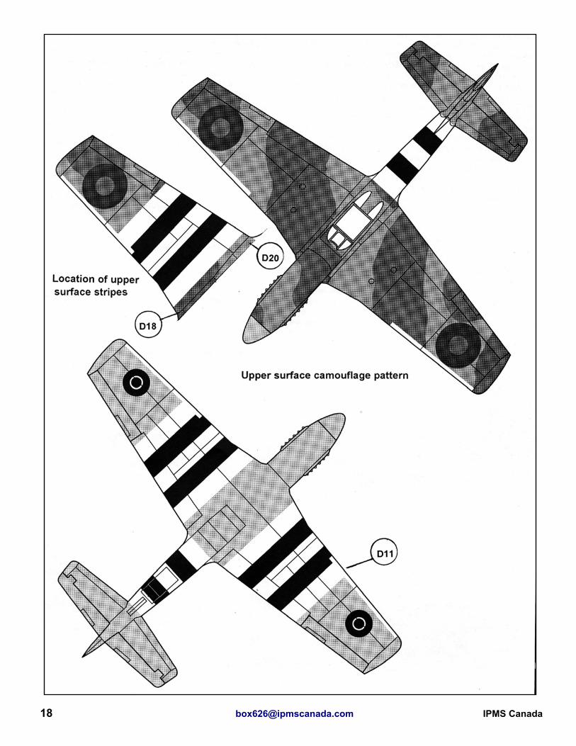
Mustang I Colour Scheme:Dark Green and Ocean Grey or Mixed Grey over Medium Sea Grey. 18” Tail band and spinner are Sky
National Markings:Upper Wings - 40” Type BLower Wings - 32” Type CFuselage - 36” Type C1Fin Flash - as indicated
Oblique camera fitted
Camera not fitted to AG470 circa Dieppe operation
AM251, ‘O’with 414 Sqn Sep 42 - Jun 44Pilot: F/Lt G. Burroughs, DFC
AG470, ‘RU-M’with 414 Sqn Jun 42 - Dec 42 Pilot: P/O Hollis Hills
No known photos exist of AG470. Scheme and markings are speculative based on other 414 Sqn aircraft
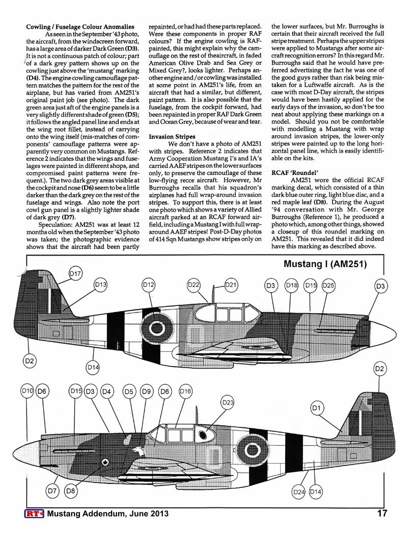
AM251 markings scheme shown in the period post-Sep 43 and pre-D-Day. Rudder was regular camouflage in May 43.
24” x 24” fin flash on AM251
Replacement rudder fitted circa Sep 43. Solid dark colour (US Olive Drab?)
3Mustang Addendum, June 2013
4 [email protected] IPMS Canada
Notes for RCAF Mustang Mk.I ProfilesAG470 Service History26 Feb 42 Shipped from USA to Lockheed Abbotsinch for re-assembly11 Jun 42 414 Sqn23 Dec 42 240 hr. Inspection at A.T. Oxford08 Feb 43 51 MU18 Aug 44 38 MU13 Mar 47 Stuck Off Charge (SOC)
AG470 Marking NotesAG470, RU-M, circa August 1942. No nose art or RCAF Roundel applied. No oblique camera fitted.
No known photos of AG470 in 414’s hands, so the scheme and markings presented are a best guess, based on photos of other 414 Sqn aircraft and the marking practices in effect at the time of OPERATION JUBILEE, the Dieppe landing operation on 19 Aug 42.
AM251 Service History18 Jan 42 USA to UK29 Jul 42 Abbotsinch Lockheed06 Sep 42 414 Sqn31 May 43 414 Sqn20 Mar 44 Battle Damage Cat. AC06 Apr 44 49 MU15 Jun 44 414 Sqn19 Jun 44 Missing in action
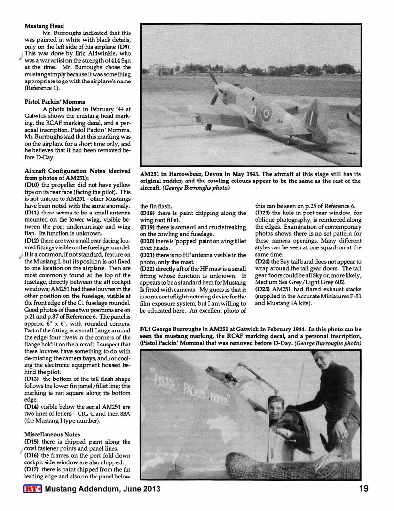
AM251 Marking NotesNose Art and colour scheme evolution (confirmed from several period photos of ‘O’, except as noted)
• May ’43 – RCAF Roundel, with original Grey and Green rudder. Paint finish is in good condition with no heavy weathering evident.
• Sep ’43 – RCAF Roundel and Mustang head, with replacement rudder painted in a solid dark colour. May have been fresh MAP Dark Green, or US Olive Drab. Much weathering in evidence.
• Feb ’44 – RCAF Roundel, Mustang head, “Pistol Packin Momma” carried at this time. Noticeable weathering is visible. Based on paint pattern ‘landmarks’, the paint job dates from Sep 43
• Jun ’44 – RCAF Roundel, Mustang head (George Burroughs, AM251’s regular pilot, believes that “Pistol Packin’ Momma” was removed prior to D-Day)
General NotesAll Mustang Is delivered to Britain were painted in Brown/Green/Sky Gray, DuPont’s ‘equivalents’ of British MAP colours for the Temperate Land Scheme, with brown spinners. Therefore both aircraft illustrated were repainted, or at least partially repainted, into the Day Fighter Scheme in the UK. The RAF Day Fighter Scheme was introduced in August 1941. This consisted of Dark Green and ‘Mixed Grey’ or Ocean Grey on the upper surfaces, with Medium Sea Grey lower surfaces.
So-called ‘Mixed Grey’ was the orignal formula for what was later named Ocean Grey. It was created by mixing seven parts Medium Sea Grey and one part Night (which is not a pure Black; it has a bluish tone). Photo evidence of the period shows a wide variety of shades resulted from this mixing.
Depending on who you’re reading, Mixed Grey was either:
• the first colour ‘spec’d’ for the Day Fighter Scheme, and it was superseded by the new colour, Ocean Grey, or
• introduced due to a shortage of Ocean Grey
If you want to visit a really great blog site that very intelligently discusses the field of American paint on aircraft supplied to the RAF, you must check out this site run by Nick Millman:
http://amair4raf.blogspot.com/2009/01/welcome-to-amair4raf.html
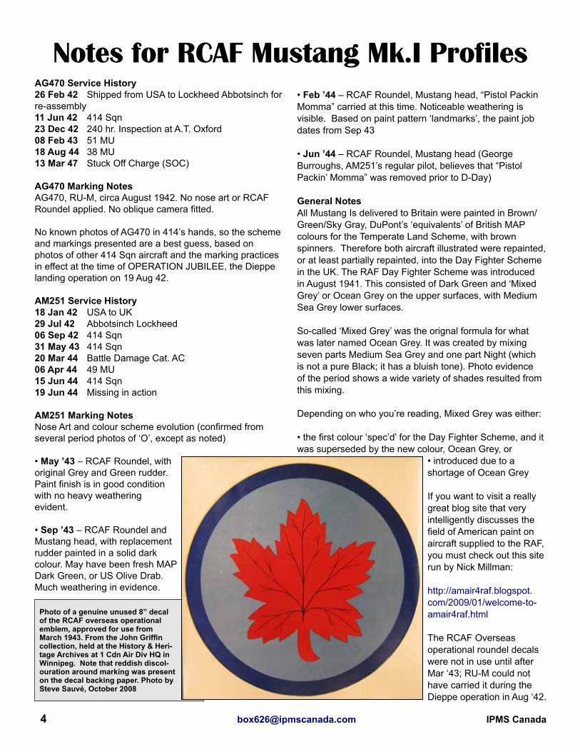
The RCAF Overseas operational roundel decals were not in use until after Mar ‘43; RU-M could not have carried it during the Dieppe operation in Aug ‘42.
Photo of a genuine unused 8” decal of the RCAF overseas operational emblem, approved for use from March 1943. From the John Griffin collection, held at the History & Heri-tage Archives at 1 Cdn Air Div HQ in Winnipeg. Note that reddish discol-ouration around marking was present on the decal backing paper. Photo by Steve Sauvé, October 2008

5Mustang Addendum, June 2013
Through the years I have been read-ing model magazines and on various mod-elling web sites, and I have been amazed by very obvious mistakes and the lack of basic research. Landing gear on back-wards, wrong colours and even chrono-logical anomalies have been printed or posted. Even very well-known aircraft are not safe from these faux pas.
Everyone knows how to do a Mus-tang, right? Not really, as Tom Cleaver on Modeling Madness felt moved to do a ‘How to’ for Merlin Mustangs. The Allison Mustang is even more poorly represented, as several very common, and easily cor-rected, mistakes continue to appear. That is the thrust of this article, not to super detail an Allison Mustang, rather to correct several of the more glaring errors in the 1/48 scale Accurate Miniatures kit, and to point out some of the more common build-
ing errors with the Allison Mustang.
When Adolph Hitler enacted the ancestry race laws in Nazi Germany, he forced a young aircraft designer to leave Germany and move to the USA. This single act was the final nail that would eventually condemn the Luftwaffe in WWII. The engineer soon found work at an up-and-coming company by the name of North American (NA). It was here that Edgar Schmued, who had been working for Messerschmitt, and did a lot of the detail design of the Bf 109, was able to continue designing ‘his’ fighter. He teamed up with ‘Dutch’ Kindelberger and the fighter rapidly took form. Schmued used the latest information from Europe, and the latest aeronautical data. His fighter was equipped with a laminar flow wing, and used the ‘Meredith Effect’ to eliminate the drag of the radiator and scoop. NA purchased data from Curtiss pertaining to the ‘advanced’ XP-46 project (http://en.wikipedia.org/wiki/Curtiss_XP-46). The data was found to be useless to NA’s needs as the Mustang design was already
more advanced than the XP-46.All that North American needed was a
source of funds to build Schmued’s fighter. When the British Purchasing Commis-sion (BPC) approached North American to build P-40s for the RAF, NA jumped at the chance to have the BPC and the RAF pay the final development costs for their new fighter. Final detail work, production
1/48 RCAF Mustang Mk.I - Part 1-
One modeller’s idea of how to build a 1/48 Allison-Powered Mustang, flown by P/O Hollis Hills, 414 Sqn, RCAF, Dieppe, 1942...
INTRODUCTION
THE MUSTANG’S GENESIS
by Bruce ArcherIPMS Canada C#3195IPMS OrlandoKissimmee, Florida, USA
List of Items Used
Accurate Miniatures Kit 3410, RAF Mustang IA
Ultracast: 48031 Mustang I Conversion48014 Early Production P-51 Seat48070 Early Mustang Flared Exhaust
Eduard Part B-6, from a P-39/P-400 kit
Arrow Graphics D-35-48 Pilot Officer Hollis Hills’ Mustang I at Dieppe
Aeromaster Decals No. 48-106 “Early Mustangs”
6 [email protected] IPMS Canada
drawings and the cutting of metal took 120 days and the first Mustang was rolled out, on T-6 Texan wheels and minus an engine. Thus, the Mustang was born, and, when eventually fitted with the superb Rolls-Royce Merlin, evolved into the best long-range escort/air superiority fighter of WWII, but that story is for another time.
The Mustang was originally equipped with a GM Allison V-1710 12 cylinder engine. The Achilles heel of this engine was its single stage, single speed super-charger.
So maybe you’re thinking that the Alli-son Mustang wasn’t a good aircraft? Noth-ing could be further from the truth. What the British got in the Mustang I was a mag-nificent low-level fighter. Below 15,000 feet it was one of, if not THE fastest fighters in the world. It had heavy armament (4 x 0.5” and 4 x 0.303” Browning machine guns), a good supply of ammo, and, importantly, lots of fuel for a long range (a detail now known as ‘combat persistence’). Because of its altitude limitations, the RAF used the Mustang I for low-level armed recce ops, Army cooperation, and interdiction. The Mustang I soon replaced Tomahawks and Lysanders in the Army Cooperation role. RCAF Nos. 400 and 414 Squadrons re-equipped with the Mustang I in the late summer of 1942 and No. 430 Squadron re-equipped with the Mustang I in the spring of 1943. The only Allison Mustang the RCAF flew operationally was the Mus-tang I. The Mustang started performing armed recce missions over the Continent, using the oblique camera mounted behind the pilot. By November of 1943, Nos. 400, 414, and 430 Squadrons became part of the 2nd Tactical Air Force (2TAF). By D-Day 430 Sqn had re-equipped with Spitfire FR Mk.XIV, and by 1945 both 400 and 414 Sqns had converted to other types.
How successful was the Mustang I in its roles? In 1944, the RAF started to convert Mustang I Squadrons to various marks of Spitfires, Mosquitos and Ty-phoons, but not because these aircraft were better; rather the RAF was simply running out of usable Allison Mustang airframes. The RAF tried to recover any Mustang crash, as spare parts were becoming a problem. There were at least 60 RAF Mustang Is in Squadron service at the war’s end. After the war, the remaining Allison Mustangs were pulled from service.
The aircraft I modelled is Mustang I, AG470, RUfM of No. 414 Squadron,
RCAF, flown by Pilot Officer (P/O) Hollis Hills who had the first Mustang ‘kill’ during the OPERATION JUBILEE, the il-fated Dieppe operation, on 19 August, 1942. Of course, everyone ‘knows’ that Hills’ Mustang:
♦was painted in Ocean Grey, Dark Green and Medium Sea Grey, ♦wore Sky codes, tail band and spin-ner, ♦carried the RCAF’s maple leaf over-seas emblem and sported a ‘horse head’ insignia. ♦was equipped with an oblique cam-era pointed to port.
In researching the airframe (and infor-mation was being received as I was about to apply the decals) several conundrums became apparent. The first was the Ocean Grey. Most images of 414 Sqn’s Mustangs indicate the colour was Mixed Grey. Mixed Grey was introduced due to a shortage of Ocean Grey, was (in the official formula, at least) prepared by mixing seven (7) parts Medium Sea Grey and one (1) part Night.
The leading edge ID stripes have been presented extending from the wing tip to the outer guns, and then inboard of the guns to the wing root. Looking at images it appears the ID stripe extended only to the outer guns.
The real surprise was that the Air Ministry in July of 1942, one month prior to Dieppe, said it was disappointed in the lack of progress in fitting cameras to Mus-tang type aircraft (these were recorded minutes from a RAF/Air Ministry meeting. Cameras began to appear in Sqn aircraft about January of 1943, many thanks to Colin Ford for the minutes!). Therefore Hollis Hills’ Mustang was not fitted with a camera (of course I found out after I fitted the camera!).
Many artists have reproduced the aircraft having the RCAF’s maple leaf overseas roundel decal and horse head. Again, most of the aircraft in 414 Sqn. did not have these items at Dieppe. So to sum this all up, Hills’ Mustang was a Mk.I:
♦with no camera, ♦Mixed Grey, Dark Green, and Medium Sea Grey camo, ♦with Sky band, codes, and spinner. ♦The Maple Leaf and ‘horse head’ insignia were not carried.
There were a surprising number of Allison Mustang variants. Table No.1 gives more detail on the details of each variant, but here is a quick look at each.
Mustang I - The Mustang I was the first variant, used exclusively by the RAF and RCAF. It was armed with 2 x 0.5” cal. and 4 x 0.303” cal machine guns in the wings, and 2 x 0.5” cal. machine guns in the engine cowling ‘cheeks’. All were delivered to the RAF (as were all Allison Mustangs) painted in:
♦a dark green, ♦a shade of brown, and ♦a grey very close to the RAF/FAA shade ‘Sky Grey’ of American manu-facture.
I have not been able to find out with certainty if these paints these were produced by DuPont. The Mustang I had a narrow carb intake, a narrow chord Curtiss Electric three-bladed prop and an adjustable radiator intake. The Mustang I was able to carry both oblique and vertical cameras.
Mustang IA - Mustang I with 4 x 20 mm Hispano cannons replacing the machine guns.
P-51 - US version of the Mustang IA
F-6A – Recon version of the P-51. The F-6A could carry an oblique camera behind the pilot, and the ability to carry a vertical camerais suspected, but not confirmed.
A-36A -The A-36 was the dive-bomb-er version of the Mustang, with 4 x 0.5” cal. wing guns, 2 x 0.5” cal. ‘cheek’ guns, pylons under the wings, and dive flaps on top and below the wings. The A-36 had the fat intake, which contains an air filter, and the inlet to the radiator is now fixed (i.e., no variable opening). The A-36 also was equipped with a newer, wider chord Curtiss Electric propeller.
P-51A - This was the fighter version of the A-36. Cheek guns and dive flaps deleted. The pylons were repositioned and plumbed for drop tanks. A new Allison V-1710 with more horsepower was fitted, along with the new wider chord Curtiss Electric propeller.
Mustang II - RAF version of the P-51A. The Mk.II was able to carry the oblique camera behind the pilot, and was often fitted with vertical and additional oblique cameras.
F-6B - American recon version of the P-51A that had provisions to carry a verti-cal camera between the radiator exhaust and the tail wheel.
THE SUBJECT - AG470
ALLISON MUSTANGS
THE MUSTANG’S RECORD
7Mustang Addendum, June 2013
The Accurate Miniatures (A-M) Allison Mustang kits set new standards when they were released in the early 1990s. Moulded in either a medium grey or dark olive drab plastic, the panel lines are finely executed; mould-ing is generally crisp, and the fit is excellent to very good. These kits come in A-M’s false bottom box (plastic above, and the decals, instructions and clear parts below). The original instructions are pretty pathetic, so try to get the newer versions of the instruc-tions (accurate-miniatures.com). You can download some of the later instructions from their website. Still not the best (there are several errors in the new instructions, so beware) they are a vast improvement over the originals. De-cal options tend to be ho-hum, and you get two options at the most. The decals themselves are very usable. A-M have released the Mustang IA, P-51, P-51A, A-36A, F-6A and F-6B to date. The clear parts are commendably clear, but only one style of camera port ‘quarter glass’ is provided (the oval type), and only if the kit has the oblique camera option. The F-6 kits do not come with the provisions for the vertical camera.
As in all kits, the A-M Mustangs have some problems (If you ever find the per-fect kit, I want to know about it!). Most are relatively minor, but annoying:
♦First is the propeller. It looks like some-one stuck a scale 2 x 8 wood plank on the hub and called it the prop. It needs replac-ing. There were two different props used by the Allison Mustang. The first, used on Mustang I, IA, P-51, and F-6A produc-tion, was a narrow chord Curtiss Elec-tric three bladed prop. The second prop, used by the P-51A, Mustang II, A-36 and F-6B, was a wider chord three bladed Curtiss Electric prop. The easy way to
tell the difference is that the earlier prop tips tend to be more pointed. The later prop has rounder tips.
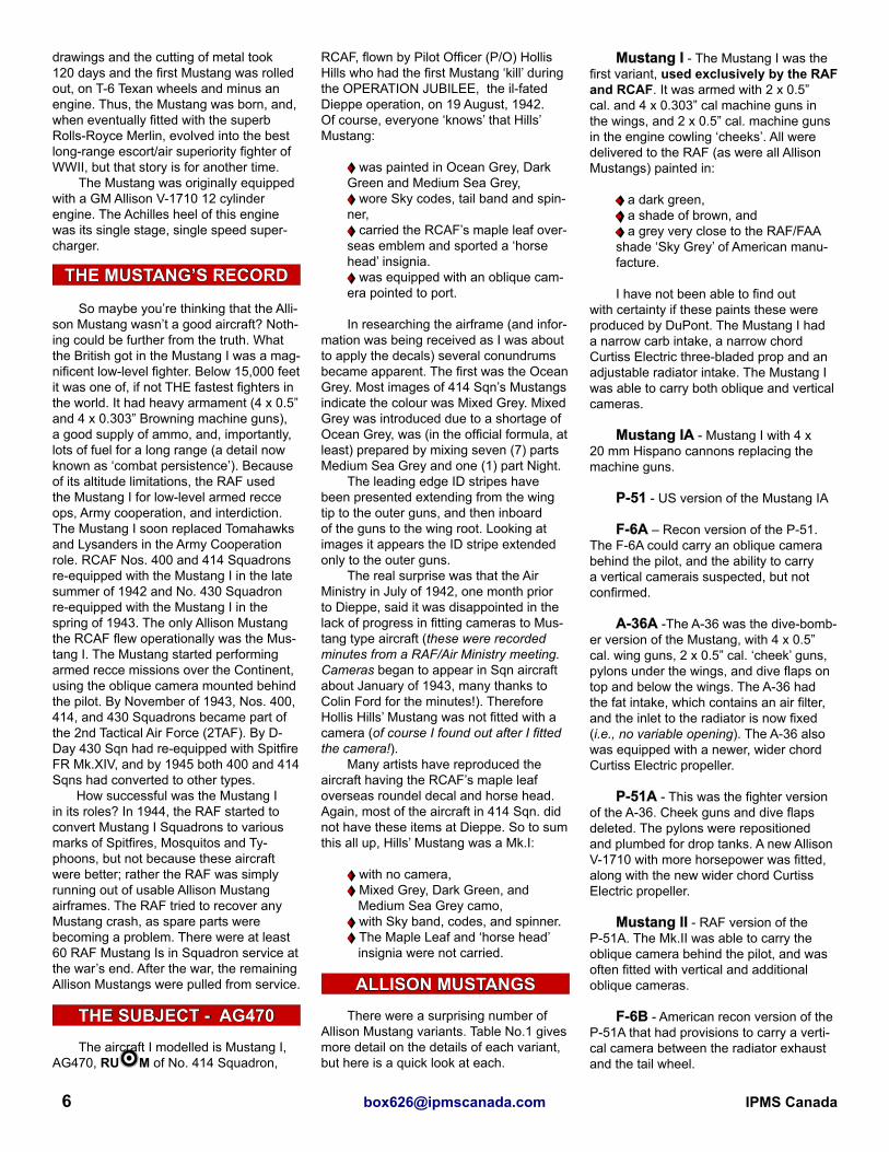
♦The next item is the lack of seat ar-mour. Although NA did not fit the armour in early deliveries of the Mustang I, they soon developed the armour, and supplied kits to add it to existing a/c. The RAF also developed seat armour and had it manu-factured locally ♦Only one style of camera window opening is supplied for the oblique cam-era. I have counted at least five, and the camera window provided is only for the port side. There were bulged, egg shapes, round, Perspex, or metal and could be found on either side. For the F-6A and B, the provisions for the vertical camera is located between the radiator and the tail wheel, and its access hatch is not pro-vided. ♦Finally, one error found in this kit and all Mustang kits which is difficult to fix are the main wheel wells. The rear wall in the kit did not exist on the real airplane. Rather the main wing spar formed the rear of the well, and it ran straight from wingtip to wingtip. So the kit’s rear well wall needs to be removed, and stiffeners added to be 100% accurate. I don’t do it as it does require a bit of work. Photo 1 shows the rear of the wheel well
wheel for the Allison Mustang.Fixes for the shortcomings which are contained within the A-M kit (with the exception of the wheel wells) are fairly common, and easy to do:
♦the many cockpit interior sets have the seat armour♦ Ultracast makes a late prop and a Mustang I conversion, seats, ex-hausts, and other bits♦ Falcon and Squadron have vacu-formed canopies. ♦others bits such as new 20 mm cannons can be acquired from the Hasegawa Typhoon and Hurricane kits. ♦ The earlier pointed and later paddle bladed Curtiss prop is found in the Eduard P-39/P-400 kits.
So all is not lost, and detail parts can be had easily.
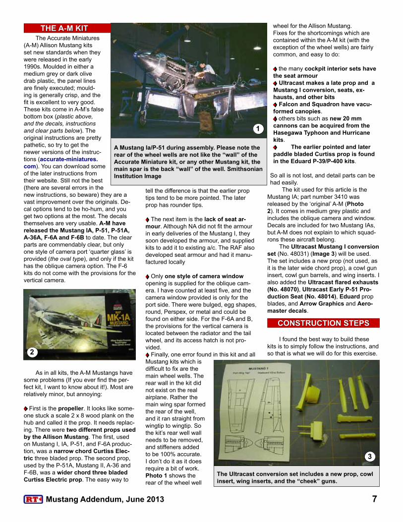
The kit used for this article is the Mustang IA; part number 3410 was released by the ‘original’ A-M (Photo 2). It comes in medium grey plastic and includes the oblique camera and window. Decals are included for two Mustang IAs, but A-M does not explain to which squad-rons these aircraft belong.
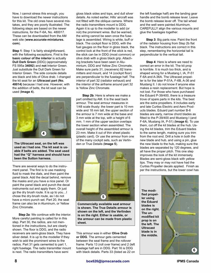
The Ultracast Mustang I conversion set (No. 48031) (Image 3) will be used. The set includes a new prop (not used, as it is the later wide chord prop), a cowl gun insert, cowl gun barrels, and wing inserts. I also added the Ultracast flared exhausts (No. 48070), Ultracast Early P-51 Pro-duction Seat (No. 48014), Eduard prop blades, and Arrow Graphics and Aero-master decals.
I found the best way to build these kits is to simply follow the instructions, and so that is what we will do for this exercise. 2
3
A Mustang Ia/P-51 during assembly. Please note the rear of the wheel wells are not like the “wall” of the Accurate Miniature kit, or any other Mustang kit, the main spar is the back “wall” of the well. Smithsonian Institution Image
The Ultracast conversion set includes a new prop, cowl insert, wing inserts, and the “cheek” guns.
THE A-M KIT
1
CONSTRUCTION STEPS
8 [email protected] IPMS Canada
Now, I cannot stress this enough, you have to download the newer instructions for this kit. The old ones have several mis-takes, and they are poorly illustrated. The following steps are based on the newer instructions, for the F-6A, No. 480017. These can be downloaded from the AM web site (www.accurate-miniatures.com).
Step 1: Step 1 is fairly straightforward, with the following exceptions. First is the basic colour of the interior is actually Dull Dark Green (DDG) (approximately FS 595a 34092) and not Interior Green. Just substitute the Dull Dark Green for Interior Green. The side console details are black and bits of Olive drab. I changed the kit seat for an Ultracast part (No. 48014) because I had one. However, with the addition of belts, the kit seat can be used (Image 4).
There are several ways to do the instru-ment panel. The first is to use masking fluid to mask the dials, and then paint the panel black. Add the decal behind, remove the masks and you have a nice panel. Or paint the panel black and punch the decal instruments out and apply them. Or just go the dry brush route. It is up to you…I chose the dry-brush route, as I do not have a micro punch set. Part 20, the seat frame can also be in Aluminum, or Yellow Zinc Chromate.
Step 2a: We continue with the interior. More careful painting is called for in this step. Part 30, the radios, are not men-tioned in the instructions, but are clearly shown. The floor is DDG, and the radio receivers are semi-gloss black. They have silver detail. It is up to the modeller if they wish to add the prominent wires to the radios. Part 31 gets cemented to part 1, right fuselage. The radio transmitter mount is next. The radio transmitters have semi
gloss black sides and tops, and dull silver details. As noted earlier, Hills’ aircraft was not fitted with the oblique camera. Where the radio transmitters mount is DDG. Again it is up to the modeller to add (or not) the prominent wires. But be warned, the wiring cannot be seen once the fuse-lage is assembled. Wiring is white, buff or black. The cockpit floor is DDG, with the fuel gauges on the floor in gloss black, the control lock at the front of the stick is red, the stick can be in DDG (most common) or olive drab with a gloss black grip. Attach-ing brackets have been seen in Alu-minium, DDG and Yellow Zinc Chromate. Make sure parts 31, (receivers) 82 trans-mitters and mount, and 14 (cockpit floor) are perpendicular to the fuselage half. The interior of part 32 (radiator exhaust) and the interior of the airframe around part 32 is Yellow Zinc Chromate.
Step 2b: Here is where we make a part omitted by AM. It is the seat back armour. The seat armour measures in 1/48 scale thusly: the lower part is 10 mm wide and 18 mm tall, the upper section of the armour is 7 mm wide at the base and 3 mm wide at the top, with a height of 6 mm. 1 mm of the upper section overlaps the lower section when assembled. The overall height of the assembled armour is 23 mm. Make it out of thin sheet plastic (plastic card). Or use the armour from one of the many cockpit sets, such as Verlin-den or True Details (Image 5).
This armour was in either Olive Drab or DDG. The armour gets cemented between the seat frame and the rollover frame. Parts 13 (roll over frame) and 2 (left fuselage half are in DDG. Part 16 is DDG with black details. Parts 33 (listed as 22 on
the left fuselage half) are the landing gear handle and the bomb release lever. Leave the bomb release lever off. The tail wheel and the well were painted Aluminum. CAREFULLY align the various mounts and glue the fuselages together.
Step 3: Big parts now. Paint the front of the radiator housing from Step 2b flat black. The instructions are correct in this step, remembering the horizontal tail is perpendicular to the vertical tail.
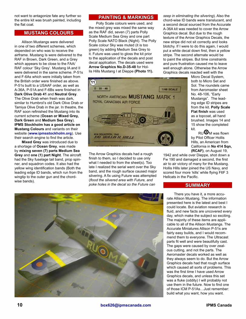
Step 4: Here is where we need to correct an error in the kit. The kit prop is horrible. It is much too thick, and is shaped wrong for a Mustang I, IA, P-51 F-6A and A-36A. The Ultracast propel-ler is for the later P-51A, F-6B, A-36 and Mustang II. I do not know if anyone else makes a resin replacement. But hope is not lost. For those who have purchased the Eduard P-39/400, there is a treasure trove of spare parts in the kits. The best are the extra propellers. It includes early and late Curtiss Electric and Aero Prod-ucts blades. Eduard part number B-6 blades are early, narrow chord blades as fitted to the P-39/400 and Mustang I (and F-6A, Mustang IA, P-51) (Image 6). To use them, cut off the kit blades at the hub. Us-ing the kit blades, trim the Eduard blades to the same length, making sure you trim from the root end. Drill a hole in both the new blade and hub, and using a pin, glue the new blade to the hub, making sure the blades are separated by 120 degrees, and all have the proper pitch. This one step improves the look of the kit immensely. Blades are semi-gloss black with yellow tips. They may or may not have had the Curtiss Propeller decals applied. Finish as per the instructions, but the lower cowl has
4
5
6
The Ultracast seat, on the left was used as I had one. The kit seat is us-able if belts are added. The seat used had the “Q” harness and should have been the Sutton harness.
Commercially available seat armour is shown. The True Details armour is shown on the left, and the Verlinden is on the right. Either is usable, or the armour can be made from plastic sheet.
The modi-fied propel-ler using the Eduard blades is on the right. The un-modified kit prop is on the left. The Ultracast blade is in the middle.

9Mustang Addendum, June 2013
to be trimmed to allow the Ultracast cowl gun insert to be added. Remember to measure twice and cut once.
Step 5: Here is where the most common building error in Allison Mus-tangs occurs. With Allison Mustangs, the hydraulic system was different than the system used in Merlin Mustangs. The wheel doors (parts 28R and 28L) re-mained in the ‘up’ or closed position at all times, unless the gear was cycling. The in-structions hint that this is the way it should be, but do not tell you this IS the way it actually occurred. So the wheel wells, gear doors, and struts, should be aluminum paint. The wheels being left in natural magnesium or aluminum. Replacement gear struts were often seen in Neutral Grey. Delete parts 35 and 42. Trim the wheel doors to fit in the up position, and glue them that way (Photo 7). Omit the drop tanks as the Mustang I could not carry them. When the wing is assembled, trim the leading edge as per the Ultracast instructions and add the inserts (Photo 8). The better at cutting you are, the better these will fit (trust me, I know!). Using
the Ultracast instructions, modify the shell ejection ports on the underside of the wing (Photo 8). Remember to remove the three identification lights from under the starboard wing.
Step 6: Assemble the remainder of the kit as per the instructions. The Ultracast exhausts were used (Photo 9). If you use the Malcolm hood, delete the antenna and install a whip antenna from your favourite medium. It must
be noted here that most Mustang Is (all of the im-ages I have seen) did not use the Malcolm Hood. These were seen mainly on Mustang IA, Mustang II, and F-6B in the European Theatre. Hills’ Mustang I did not have the Malcolm Hood. If you do decide to use the Malcolm Hood on a future project remem-ber to add the tracks the hood slides on. The IFF antenna was a dipole under the starboard wing. The ‘cheese cutter’ IFF an-
tenna was not fitted. Also, the RAF had changed to UHF radios, and did away
with the antenna wire. The actual antenna ran up inside the antenna mast. But (there
is always that pesky “but”!) there are im-ages of Mustang Is with the antenna wire. So check those references! I deleted the antenna wire. Image 10 gives a view of the completed cockpit. The clear parts, although very clear, were dipped in Future.
The kit did not pose any problems during assembly. However I had added the camera. After the aircraft was gloss coated for the decals, I found out that AG470 did not have an oblique camera fitted. I did manage to remove the camera and mount without doing any damage.
After the removal of the camera and mount the model was promptly dropped and needed multiple repairs. I did keep breaking off the pin for the prop to mount on. During the build, which started in April, I moved from New Jersey to Florida, and had two computer meltdowns.
Aeromaster RAF national insignia were used as I had them, and they looked
better to me. I also noticed some filler
shrinkage (measure three times, then cut once!) from where the Ultracast bits were added. The fill-er used was Squad-ron White Stuff. In the future I will be using 3M Acryl-Blue Spot putty as I find it shrinks less than other solvent based fillers.
When I went to paint the kit, I found my compressor had been damaged in the move, and the box containing my airbrush was miss-ing. Fate had taken an unkind interest in this build, and I did
8
7
9
10
This view shows the wheel doors in the “up” position and the modified shell ejection ports.
The wing insert on the port wing. The amount of filler is an indication of the not-so-precise cuts made.
The completed cockpit. Note the colour, Dull Dark Green.
The Ultracast exhausts (top) were used. The kit exhausts are on the bottom.
CAMERA or NOT?
10 [email protected] IPMS Canada
not want to antagonize fate any further so the entire kit was brush painted, including the flat coat.
Allison Mustangs were delivered in one of two different schemes, which depended on who was to receive the airframe. Mustang Is were delivered to the RAF in Brown, Dark Green, and a Grey which appears to be close to the FAA/RAF colour ‘Sky Grey’. Mustang IA and II were delivered in the same scheme. P-51s and F-6As which were initially taken from the British order were finished as above. P-51s built to a USAAF order, as well as A-36A, P-51A and F-6Bs were finished in Dark Olive Drab 41 and Neutral Grey. The Olive Drab when fresh was dark, similar to Humbrol’s old Dark Olive Drab or Tamiya Olive Drab in the jar. In theatre, the RAF soon refinished the Mustang into its current scheme (Ocean or Mixed Grey, Dark Green and Medium Sea Grey). IPMS Stockholm has a good article on Mustang Colours and variants on their website (www.ipmsstockholm.org). Use their search engine to find the article.
Mixed Grey was introduced due to a shortage of Ocean Grey, was made by mixing seven (7) parts Medium Sea Grey and one (1) part Night. The aircraft had the Sky fuselage tail band, prop spin-ner, and squadron codes. It also had the yellow wing identification bands (Both the leading edge ID bands, which run from the wingtip to the outer gun and the chord-wise bands).
Polly Scale colours were used, and the mixed grey was mixed the same way as the RAF did, seven (7) parts Polly Scale Medium Sea Grey and one part Polly Scale NATO Black (Night). The Polly Scale colour Sky was muted (it is too green) by adding Medium Sea Grey to it. Future was used to gloss the kit prior to the application of the decals and post decal application. The decals used were Arrow Graphics No.D-35-48 for Hol-lis Hills Mustang I at Dieppe (Photo 11).
The Arrow Graphics decals had a rough finish to them, so I decided to use only what I needed to from the sheet(s). Too late I realized the serial went over the Sky band, and the rough surface caused major silvering. A fix using Future was attempted (flood the silvered area with Future, and poke holes in the decal so the Future can
seep in eliminating the silvering). Also the chord-wise ID bands were translucent, and a second decal sourced from the Accurate A-36A kit was needed to cover the Arrow Graphics decal. But due to the rough texture of the Arrow Graphics Decals, the new stripe did not sit correctly and looks blotchy. If I were to do this again, I would put a white decal down first, then a yellow stripe. The second alternate would be to paint the stripes. But time constraints and pure frustration caused me to leave well enough alone. Otherwise the Arrow Graphics decals reacted well with the
Micro Decal System, both to Micro Set and Sol. The roundels came from Aeromaster sheet No. 48-106, “Early Mustangs”. The lead-ing edge ID stripes are from the kit. Polly Scale Flat finish was used as a topcoat, all hand brushed. Images 14 and 15 show the completed kit.
RUfM was flown by Pilot Officer Hollis Hills, an American from California in No 414 Sqn, (RCAF), on August 19,
1942 and while over Dieppe, shot down a Fw 190 and damaged a second, the first air to air victory of many for the Mustang. Hollis Hills later joined the US Navy, and scored four more ‘kills’ while flying F6F 3 Hellcats in the Pacific.
There you have it, a more accu-rate Allison Mustang. The information presented here is the latest and best I could locate. But aviation research is fluid, and new facts are uncovered every day, which make the subject so exciting. The majority of these items are appli-cable to all of the Allison Mustangs. The Accurate Miniatures Allison P-51s are fairly easy builds, and I would recom-mend them to everyone. The Ultracast parts fit well and were beautifully cast. The gaps were caused by over zeal-ous cutting, and not the parts. The Aeromaster decals worked as well as they always seem to do. But the Arrow Graphics decals had that rough surface which caused all sorts of problems. This was the first time I have used Arrow Graphics decals, and unless this set was a fluke (oddity) I will probably not use them in the future. Now to find one of those ICM P-51As…Just remember: build what you want, how you want.
SUMMARY
11
MUSTANG COLOURS
PAINTING & MARKINGS

11Mustang Addendum, June 2013
I would like to acknowledge the following people for their help, and for just putting up with me:
♦My wife Dana, who encourages my hobby for the benefit of the boys and myself. ♦Joe Lyons, who plays devil’s advo-cate and keeps me honest. ♦Tom Smith, a fellow lover of Allison Mustangs. ♦Tom Cleaver, for not only interviewing Edgar Schmued, but generously sharing his notes. ♦Colin Ford, for his vast knowledge of RAF Allison Mustangs. ♦Terry McGrady, for his input. ♦and your ever-suffering Editor Steve Sauvé, for the patience during my family move to Florida and several computer failures.
I thank you all!
Allison Mustang Characteristics Comparison
About the author:Bruce Archer is a Geologist by trade; he recently moved from New Jersey to Central Florida (though he would have preferred Calgary). Fortunately, the daily sounds of radial engines and Merlins overhead from a nearby air museum have eased the transition. Bruce has been modelling for longer the he likes to remember. His major interests are Spitfires, Allison Mustangs, Zippers (F-104s), Harriers and the FAA. He has written several articles on mod-elling and aviation history and he also dabbles in N-Scale model railroading. Bruce has been married to his lovely wife Dana for seven years and they have 5-year-old triplet boys (who have started building).
♦Camoflage and Markings, “RAF Fighter Command Northern Europe 1939 to 1945, North American Mustang” Doubleday and Co., 1971
♦In Detail and Scale, “P-51 Mustang Part 1”, Squadron-Signal Publications, 1996
♦Wings of Fame, Vol.1 “North American P-51 Mustang” Aerospace Publishing, 1995
♦American Fighters of World War II, “North American P-51 Mustang” Double-day and Co., 1969
♦2nd Tactical Air Force, Vols. 1 through 3, Classic Publishing (Ian Allen Publishers), 2004 to 2006
♦Walk Around No.13, “Allison Powered Mustangs”, Squadron-Signal Publications, 1998
♦Camoflage and Markings No.16, “North American P-51 and F-6 Mustang USAAF, ETO and MTO 1942-1945”, Ducimus Books, No Date
♦Planes and Pilots, “P-51 Mustang From 1940 to 1980” , Histoire & Collections, 2003
♦Famous Fighters of the Second World War, “North American Mustang” Hanover House, 1957
♦On Target Profiles No.2 “RAF and Com-monwealth P-51 Mustangs” , Aviation Workshop Publications, No date.
♦Scale Aircraft Modeling, Vol. 17 No.8 (October, 1995) Aircraft in Detail “P-51 Mustang in RAF and Commonwealth Ser-vice”, Guideline Publications
♦Model Aircraft Monthly, Vol.4 No.4, “Mustangles”, SAM Publications
♦Air Classics, Vol. And No. Unknown (article removed from magazine) “The Al-lison Mustangs” Parts 2 and 3, Challenge Publications
♦Modeling Madness, Various Mustang articles by Tom Cleaver (www.modeling-madness.com)
♦IPMS Stockholm, “Camouflage and Markings of North American P-51 Mus-tang, Parts 1 through 4”, (www.ipmsstock-holm.org/magazine/1999/12/stuff_eng_profile_mustang1.htm)
♦IPMS Stockholm, “Modeller’s Guide to Early P-51 Mustang Variants”, (www.ipmsstockholm.org/magazine/1999/11/stuff_eng_p51early.htm)
♦Cybermodeler, “RAF Allison-Powered Mustangs” (http://www.cybermodeler.com/special/mustang.shtml)
♦E-Mail Conversations With Colin Ford on RAF modifications and camera fits on RAF Mustangs
♦E-Mail conversations with Tom Cleaver about his interview with Edgar Schmued
♦E-Mail conversations with Terry Mc-Grady about RAF Allison Mustangs, and Mustang Repainting
REFERENCES
ACKNOWLEDGEMENTS
Editor’s Note: My sincere apolo-gies to the entire membership of IPMS Canada for missing several key elements of Bruce’s Mus-tang article in RT 32/3. This PDF version is roughly what it should have looked like in the journal. - Steve
12 [email protected] IPMS Canada
13Mustang Addendum, June 2013
14 [email protected] IPMS Canada
15Mustang Addendum, June 2013

16 [email protected] IPMS Canada
17Mustang Addendum, June 2013
18 [email protected] IPMS Canada
19Mustang Addendum, June 2013
20 [email protected] IPMS Canada

21Mustang Addendum, June 2013

22 [email protected] IPMS Canada

23Mustang Addendum, June 2013
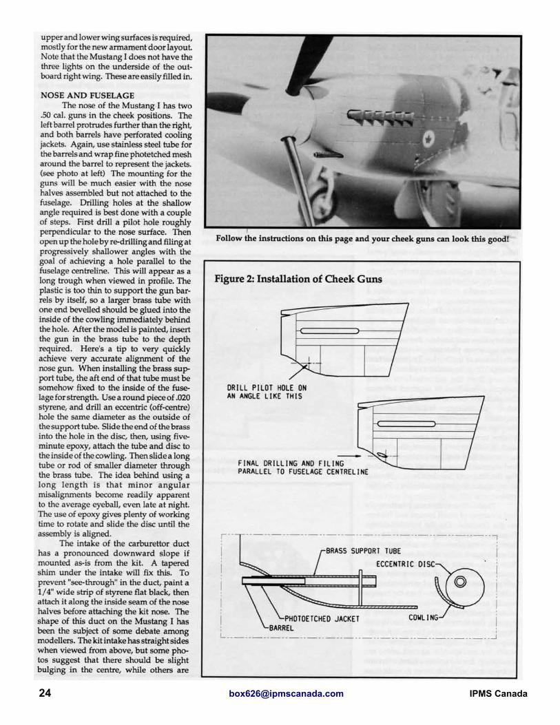
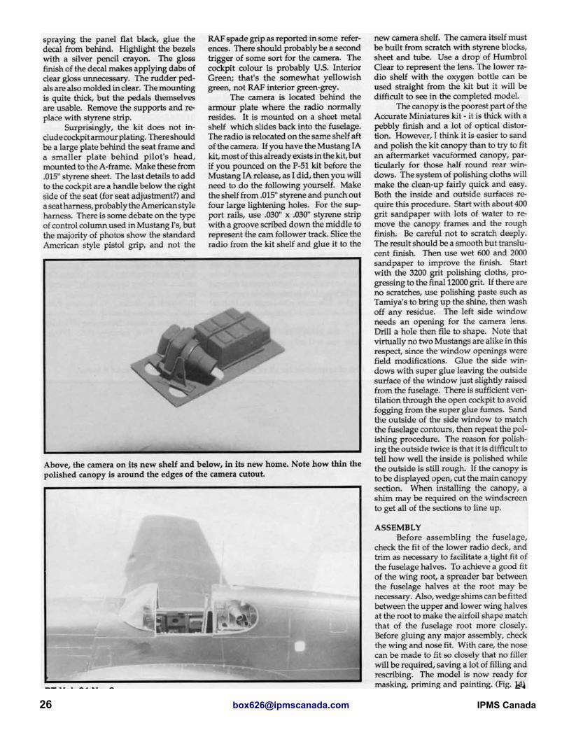
24 [email protected] IPMS Canada

25Mustang Addendum, June 2013
26 [email protected] IPMS Canada
27Mustang Addendum, June 2013

We hope you’ve enjoyed this brief look at what the members of IPMS Canada have been producing for our magazine. Today RT is a quarterly publication, in English, containing 36 pages of photos, drawings, kit reviews, model building and conversion articles, hints-n-tips, and other items of modelling interest. All content is provided by the members, for the members. We’ve also occasionally sent out a free special bonus item, such as a decal sheet, with the magazine.
Recently IPMS Canada started sending the members another publication. This is an e-newsletter called beaveRTales, which arrives in their email as a PDF document. It is sent in the periods between RT issues and unlike RT, it is more ‘newsey’. Here you’ll find such things as kit, accessory and book reviews, news from various local chapters, information on new model kits, small build and photo articles (as opposed to RT’s more detailed material), hints-n-tips, photos of members’ latest creations, quizzes, and whatever else the members send in. The newsletter will keep you up to date on what’s happening in IPMS Canada, and the rest of the modelling world.
If you’d like to find out more about IPMS Canada, just visit our website at www.ipmscanada.com. There you can find out more about our Branch and
what we provide, see some pictures of our members’ models, and even check out our ‘Fun Page’. If you like what you see, you can join right there online!