raglan - direct-fireplaces.com fileraglan coal effect balanced flue gas fire installation and...
TRANSCRIPT
RaglanCOAL EFFECT BALANCED FLUE GAS FIRE
Installation and Maintenance Instructions
Hand these instructions to the user
Model No. FBFC**MN for use on Natural Gas (G20) at a supply pressure of 20mbar in G.B. / I.E.
NB : ** denotes trim / fret variant
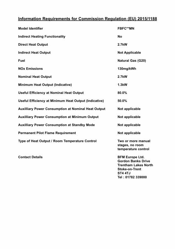
Information Requirements for Commission Regulation (EU) 2015/1188
Model Identifier FBFC**MN
Indirect Heating Functionality No
Direct Heat Output 2.7kW
Indirect Heat Output Not Applicable
Fuel Natural Gas (G20)
NOx Emissions 130mg/kWh
Nominal Heat Output 2.7kW
Minimum Heat Output (Indicative) 1.3kW
Useful Efficiency at Nominal Heat Output 80.0%
Useful Efficiency at Minimum Heat Output (Indicative) 50.0%
Auxilliary Power Consumption at Nominal Heat Output Not applicable
Auxilliary Power Consumption at Minimum Output Not applicable
Auxilliary Power Consumption at Standby Mode Not applicable
Permanent Pilot Flame Requirement Not applicable
Type of Heat Output / Room Temperature Control Two or more manual stages, no room temperature control
Contact Details BFM Europe Ltd.Gordon Banks DriveTrentham Lakes NorthStoke-on-TrentST4 4TJTel : 01782 339000
CONTENTSPAGE
Section 1 Information and Requirements
1.0 Appliance Information 31.1 Conditions of Installation 41.2 Fireplace surround & suitability 41.3 Flue Terminal Position 51.4 Shelf position 61.5 Hearths 6
Section 2 Installation of Fire
2.1 Unpacking the fire 62.2 Fireplace opening 6-72.3 Preparation of the wall 82.4 Preparation of the flue hole 92.5 Preparation of the flue pipes 102.6 Installation of the gas supply 11-122.7 Securing of the firebox to the wall 12-142.8 Preparation for mounting the flue terminal 152.9 Fitting the terminal guard 162.10 Removal & refitting of the glass frame 16
Section 3 Assembling Fuel Bed and Commissioning
3.1 Fitting the fuel bed 17-183.2 Lighting the appliance 19
Section 4 Maintenance
4.1 Removal of the Burner Assembly 194.2 Removal of the Piezo Igniter 20-214.3 Removal of the Control Valve 214.4 Removal of the Pilot Assembly 21-22
Model number FBFC**MN is manufactured by:-
BFM Europe LtdTrentham LakesStoke-on-TrentStaffordshireST4 4TJ
2
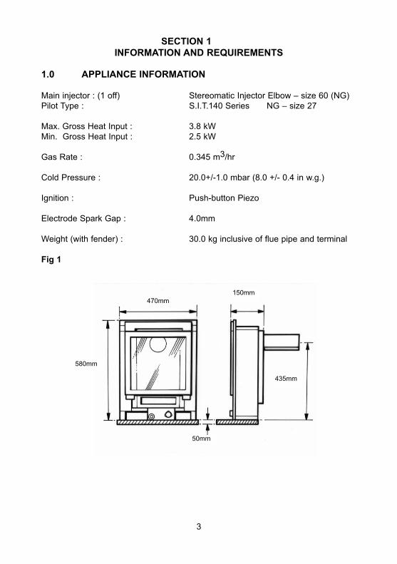
SECTION 1INFORMATION AND REQUIREMENTS
1.0 APPLIANCE INFORMATION
Main injector : (1 off) Stereomatic Injector Elbow – size 60 (NG)Pilot Type : S.I.T.140 Series NG – size 27
Max. Gross Heat Input : 3.8 kW Min. Gross Heat Input : 2.5 kW
Gas Rate : 0.345 m3/hr
Cold Pressure : 20.0+/-1.0 mbar (8.0 +/- 0.4 in w.g.)
Ignition : Push-button Piezo
Electrode Spark Gap : 4.0mm
Weight (with fender) : 30.0 kg inclusive of flue pipe and terminal
Fig 1
3
470mm
580mm
50mm
435mm
150mm
INSTALLATION REQUIREMENTS
Efficiency Declaration
The efficiency of this appliance has been measured as specified in BS EN 613 : 2001 and the result is 74%. The gross calorific value of the fuel has been used for this efficiency calculation. The test data from which it has been calculated has been certified by Advantica. The efficiency value may be used in the UK Government’s Standard AssessmentProcedure (SAP) for energy rating of dwellings.
1.1 CONDITIONS OF INSTALLATION
It is the law that all gas appliances are installed only by a GAS SAFE RegisteredInstaller, in accordance with these installation instructions and the Gas Safety(Installation and Use) Regulations 1998 as amended. Failure to install appliancescorrectly could lead to prosecution. It is in your own interest and that of safety tocomply with the law.
The installation must also be in accordance with all relevant parts of the Local andNational Building Regulations where appropriate, the Building Regulations(Scotland Consolidation) issued by the Scottish Development Department, and allapplicable requirements of the following British Standard Code of Practice.
1. B.S. 5871 Part 1 Installation of Gas Fires2. B.S. 6891 Installation of Gas Pipework3. B.S. 5440 Parts 1 & 2 Installation of Flues and Ventilation4. I.S 813 : 1996 Domestic Gas Installation, issued by the National Standards Authority of Ireland.
1.2 FIREPLACE / SURROUND SUITABILITY
The fire must only be installed on a hearth it must not be installed directly ontocarpet or other combustible floor materials.The fire is suitable for fitting to non-combustible fire place surrounds and propri-etary fire place surrounds with a temperature rating of at least 150oc.If a heating appliance is fitted directly against a wall without the use of a firesurround or fire place all combustible material must be removed from behindthe trim. Soft wall coverings such as blown vinyl, wall paper etc. could beaffected by the rising hot air and scorching and/or discoloration may result.Due consideration should be made to this when installing or decorating.
4
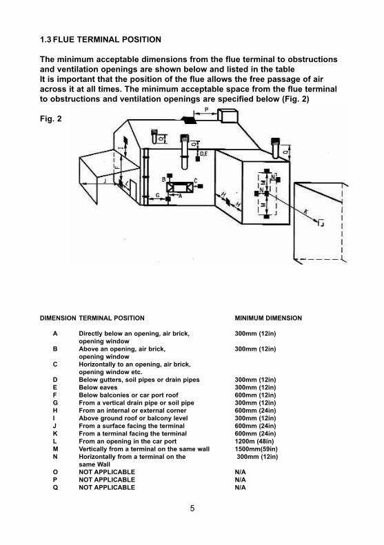
1.3 FLUE TERMINAL POSITION
The minimum acceptable dimensions from the flue terminal to obstructionsand ventilation openings are shown below and listed in the table It is important that the position of the flue allows the free passage of airacross it at all times. The minimum acceptable space from the flue terminalto obstructions and ventilation openings are specified below (Fig. 2)
Fig. 2
DIMENSION TERMINAL POSITION MINIMUM DIMENSION
A Directly below an opening, air brick, 300mm (12in) opening window
B Above an opening, air brick, 300mm (12in) opening window
C Horizontally to an opening, air brick, opening window etc.
D Below gutters, soil pipes or drain pipes 300mm (12in)E Below eaves 300mm (12in) F Below balconies or car port roof 600mm (12in) G From a vertical drain pipe or soil pipe 300mm (12in) H From an internal or external corner 600mm (24in) I Above ground roof or balcony level 300mm (12in) J From a surface facing the terminal 600mm (24in) K From a terminal facing the terminal 600mm (24in) L From an opening in the car port 1200m (48in) M Vertically from a terminal on the same wall 1500mm(59in) N Horizontally from a terminal on the 300mm (12in)
same Wall O NOT APPLICABLE N/A P NOT APPLICABLE N/A Q NOT APPLICABLE N/A
5
1.4 SHELF POSITION
The fire may be fitted below a combustible shelf providing there is a minimum dis-tance of 200mm above the top of the fire and the shelf does not project more than150mm. If the shelf overhangs more than 150mm the distance between the fireand the shelf must be increased by 15mm for every 25mm of additional overhangover 150mm.
1.5 HEARTHS
This appliance does not require the fitting of a hearth, but we do recommend thata hearth of minimum width 760mm and minimum projection forwards of 125mm isused. This recommended hearth can be manufactured from combustible or non-combustible material.
SECTION 2INSTALLATION OF FIRE
2.1 UNPACKING THE FIRE
Carefully lift the fire out of the carton. Remove the loose item packaging carefullyfrom the the pack. Check the contents as listed :-
IMPORTANT : THE CARDBOARD FITMENT THAT IS AT THE TOP OF THECONVECTION APERTURE SHOULD NOT BE REMOVED UNTIL THE APPLIANCE IS FULLY INSTALLED AND READY TO BE LIT.
DO NOT UNDER ANY CIRCUMSTANCES USE THIS APPLIANCE IF THEGLASS PANEL IS BROKEN OR NOT SECURELY FIXED TO THE FIREBOX.
Packing Check List
1off Fire box & foam seal / burner assembly1off Trim & magnets1off Boxed ceramic one piece fuel bed 1off Flue Terminal unit 1off Loose Items pack – containing:- Cable fixing kit, Section of Foil Tape
10 off rawplugs, 12 off No.8 x 10mmscrews1 off 6mm Allen Key1 off Right Hand Supply Pipe10 off No.12 x 40mm fixing screws1 off heat deflector
6
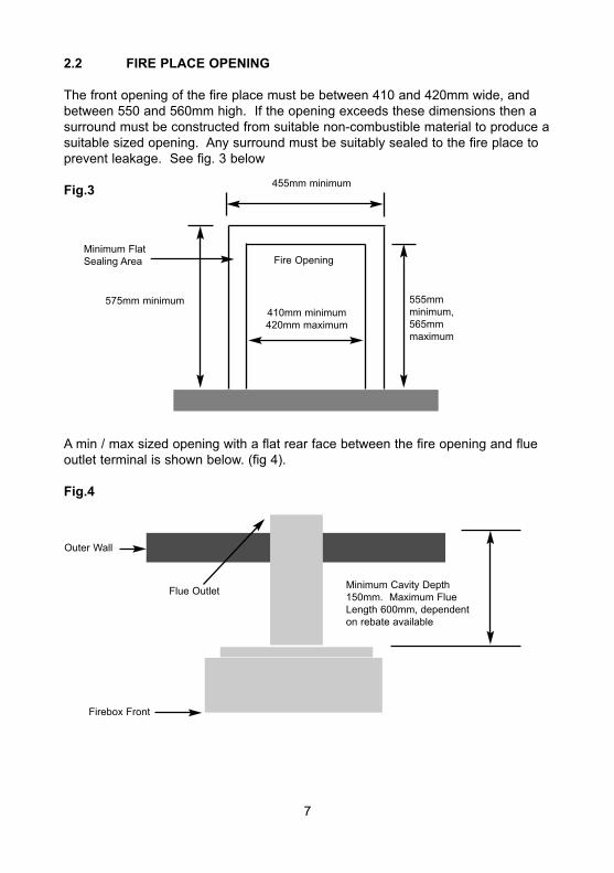
2.2 FIRE PLACE OPENING
The front opening of the fire place must be between 410 and 420mm wide, andbetween 550 and 560mm high. If the opening exceeds these dimensions then asurround must be constructed from suitable non-combustible material to produce asuitable sized opening. Any surround must be suitably sealed to the fire place toprevent leakage. See fig. 3 below
Fig.3
A min / max sized opening with a flat rear face between the fire opening and flueoutlet terminal is shown below. (fig 4).
Fig.4
7
575mm minimum
455mm minimum
Fire Opening
410mm minimum420mm maximum
555mmminimum, 565mmmaximum
Minimum FlatSealing Area
Minimum Cavity Depth150mm. Maximum FlueLength 600mm, dependenton rebate available
Firebox Front
Outer Wall
Flue Outlet
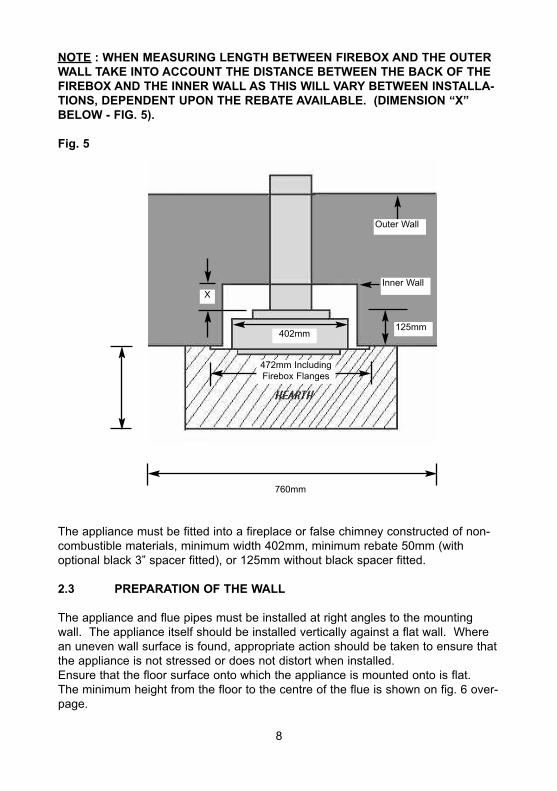
NOTE : WHEN MEASURING LENGTH BETWEEN FIREBOX AND THE OUTERWALL TAKE INTO ACCOUNT THE DISTANCE BETWEEN THE BACK OF THEFIREBOX AND THE INNER WALL AS THIS WILL VARY BETWEEN INSTALLA-TIONS, DEPENDENT UPON THE REBATE AVAILABLE. (DIMENSION “X”BELOW - FIG. 5).
Fig. 5
The appliance must be fitted into a fireplace or false chimney constructed of non-combustible materials, minimum width 402mm, minimum rebate 50mm (withoptional black 3” spacer fitted), or 125mm without black spacer fitted.
2.3 PREPARATION OF THE WALL
The appliance and flue pipes must be installed at right angles to the mountingwall. The appliance itself should be installed vertically against a flat wall. Wherean uneven wall surface is found, appropriate action should be taken to ensure thatthe appliance is not stressed or does not distort when installed.Ensure that the floor surface onto which the appliance is mounted onto is flat.The minimum height from the floor to the centre of the flue is shown on fig. 6 over-page.
760mm
402mm125mm
X
Outer Wall
Inner Wall
472mm IncludingFirebox Flanges
8
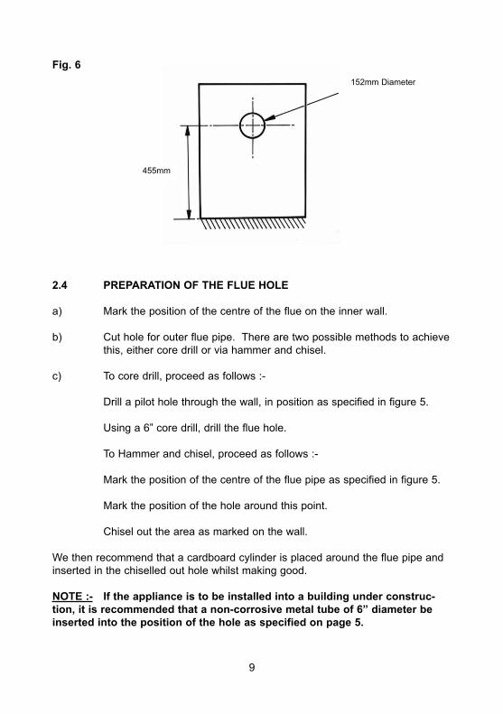
Fig. 6
2.4 PREPARATION OF THE FLUE HOLE
a) Mark the position of the centre of the flue on the inner wall.
b) Cut hole for outer flue pipe. There are two possible methods to achievethis, either core drill or via hammer and chisel.
c) To core drill, proceed as follows :-
Drill a pilot hole through the wall, in position as specified in figure 5.
Using a 6” core drill, drill the flue hole.
To Hammer and chisel, proceed as follows :-
Mark the position of the centre of the flue pipe as specified in figure 5.
Mark the position of the hole around this point.
Chisel out the area as marked on the wall.
We then recommend that a cardboard cylinder is placed around the flue pipe andinserted in the chiselled out hole whilst making good.
NOTE :- If the appliance is to be installed into a building under construc-tion, it is recommended that a non-corrosive metal tube of 6” diameter beinserted into the position of the hole as specified on page 5.
152mm Diameter
455mm
9
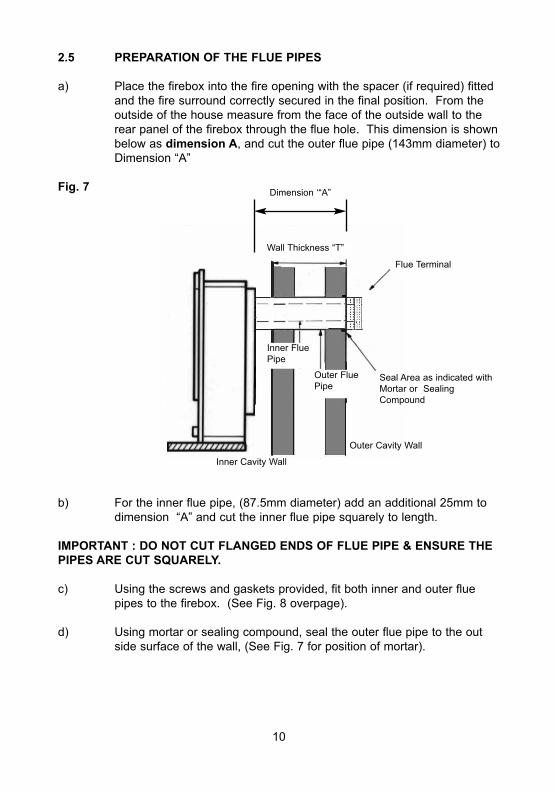
2.5 PREPARATION OF THE FLUE PIPES
a) Place the firebox into the fire opening with the spacer (if required) fitted and the fire surround correctly secured in the final position. From the outside of the house measure from the face of the outside wall to the rear panel of the firebox through the flue hole. This dimension is shownbelow as dimension A, and cut the outer flue pipe (143mm diameter) toDimension “A”
Fig. 7
b) For the inner flue pipe, (87.5mm diameter) add an additional 25mm to dimension “A” and cut the inner flue pipe squarely to length.
IMPORTANT : DO NOT CUT FLANGED ENDS OF FLUE PIPE & ENSURE THEPIPES ARE CUT SQUARELY.
c) Using the screws and gaskets provided, fit both inner and outer flue pipes to the firebox. (See Fig. 8 overpage).
d) Using mortar or sealing compound, seal the outer flue pipe to the outside surface of the wall, (See Fig. 7 for position of mortar).
Flue Terminal
Seal Area as indicated withMortar or SealingCompound
Wall Thickness “T”
Outer Cavity Wall
Inner Cavity Wall
Dimension ‘“A”
Inner FluePipe
Outer FluePipe
10
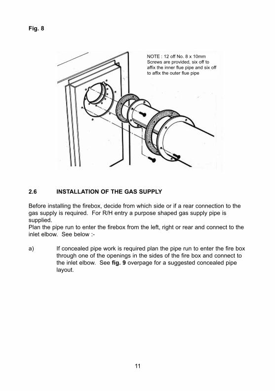
Fig. 8
2.6 INSTALLATION OF THE GAS SUPPLY
Before installing the firebox, decide from which side or if a rear connection to thegas supply is required. For R/H entry a purpose shaped gas supply pipe is supplied.Plan the pipe run to enter the firebox from the left, right or rear and connect to theinlet elbow. See below :-
a) If concealed pipe work is required plan the pipe run to enter the fire box through one of the openings in the sides of the fire box and connect to the inlet elbow. See fig. 9 overpage for a suggested concealed pipe layout.
NOTE : 12 off No. 8 x 10mmScrews are provided, six off toaffix the inner flue pipe and six offto affix the outer flue pipe
11
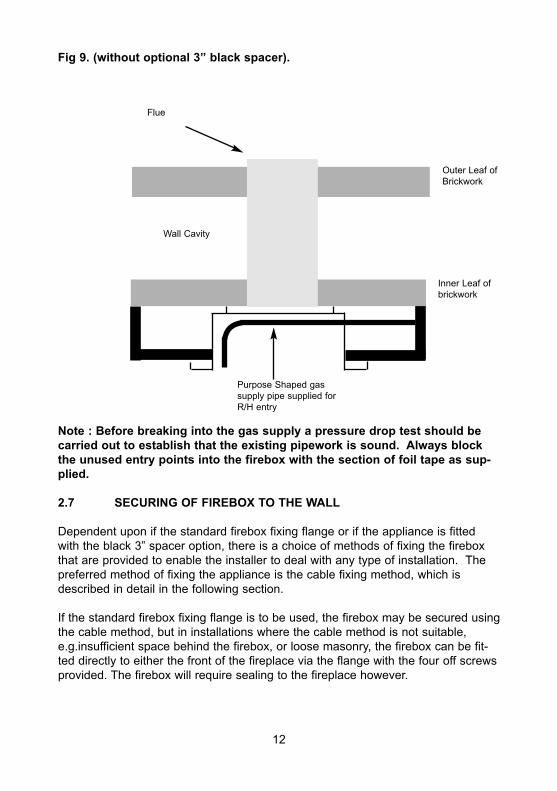
Fig 9. (without optional 3” black spacer).
Note : Before breaking into the gas supply a pressure drop test should becarried out to establish that the existing pipework is sound. Always blockthe unused entry points into the firebox with the section of foil tape as sup-plied.
2.7 SECURING OF FIREBOX TO THE WALL
Dependent upon if the standard firebox fixing flange or if the appliance is fittedwith the black 3” spacer option, there is a choice of methods of fixing the fireboxthat are provided to enable the installer to deal with any type of installation. Thepreferred method of fixing the appliance is the cable fixing method, which isdescribed in detail in the following section.
If the standard firebox fixing flange is to be used, the firebox may be secured usingthe cable method, but in installations where the cable method is not suitable,e.g.insufficient space behind the firebox, or loose masonry, the firebox can be fit-ted directly to either the front of the fireplace via the flange with the four off screwsprovided. The firebox will require sealing to the fireplace however.
Flue
Inner Leaf ofbrickwork
Outer Leaf ofBrickwork
Wall Cavity
Purpose Shaped gas supply pipe supplied forR/H entry
12
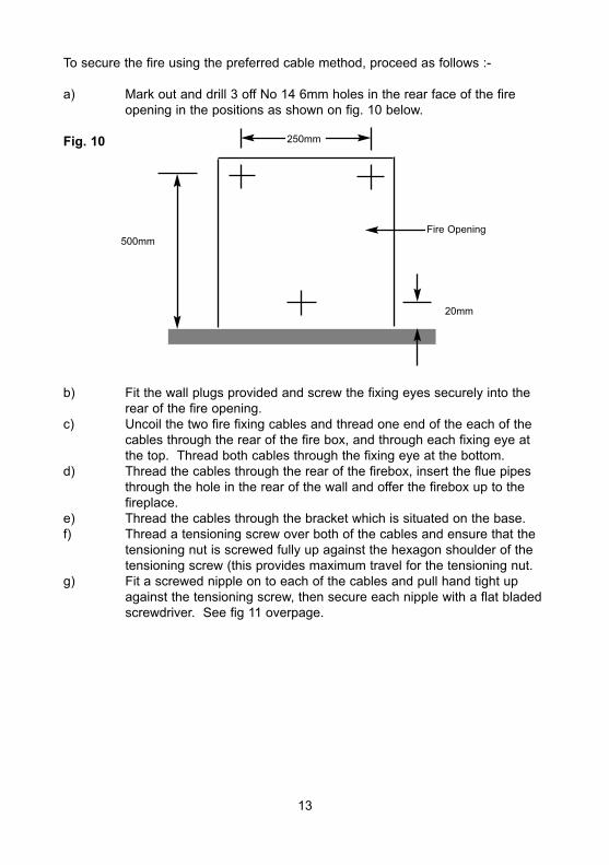
To secure the fire using the preferred cable method, proceed as follows :-
a) Mark out and drill 3 off No 14 6mm holes in the rear face of the fire opening in the positions as shown on fig. 10 below.
Fig. 10
b) Fit the wall plugs provided and screw the fixing eyes securely into the rear of the fire opening.
c) Uncoil the two fire fixing cables and thread one end of the each of the cables through the rear of the fire box, and through each fixing eye at the top. Thread both cables through the fixing eye at the bottom.
d) Thread the cables through the rear of the firebox, insert the flue pipes through the hole in the rear of the wall and offer the firebox up to the fireplace.
e) Thread the cables through the bracket which is situated on the base.f) Thread a tensioning screw over both of the cables and ensure that the
tensioning nut is screwed fully up against the hexagon shoulder of the tensioning screw (this provides maximum travel for the tensioning nut.
g) Fit a screwed nipple on to each of the cables and pull hand tight up against the tensioning screw, then secure each nipple with a flat bladed screwdriver. See fig 11 overpage.
500mm
20mm
250mm
Fire Opening
13
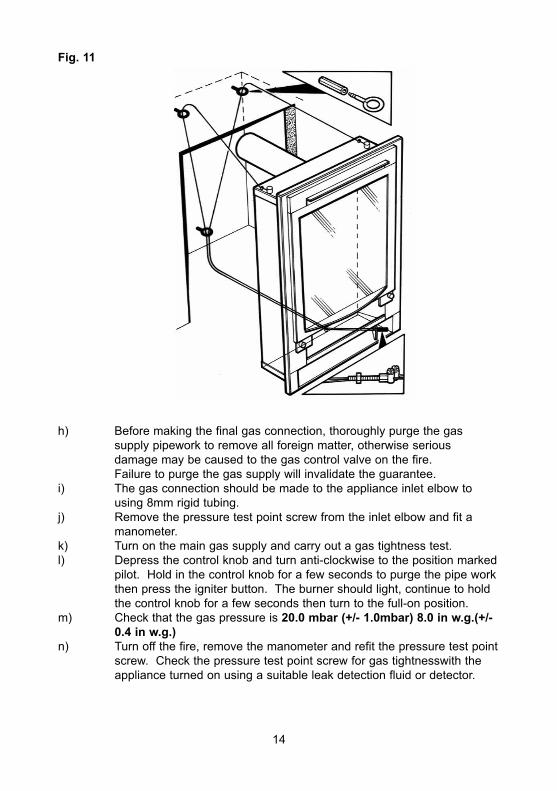
Fig. 11
h) Before making the final gas connection, thoroughly purge the gas supply pipework to remove all foreign matter, otherwise serious damage may be caused to the gas control valve on the fire. Failure to purge the gas supply will invalidate the guarantee.
i) The gas connection should be made to the appliance inlet elbow to using 8mm rigid tubing.
j) Remove the pressure test point screw from the inlet elbow and fit a manometer.
k) Turn on the main gas supply and carry out a gas tightness test.l) Depress the control knob and turn anti-clockwise to the position marked
pilot. Hold in the control knob for a few seconds to purge the pipe work then press the igniter button. The burner should light, continue to hold the control knob for a few seconds then turn to the full-on position.
m) Check that the gas pressure is 20.0 mbar (+/- 1.0mbar) 8.0 in w.g.(+/- 0.4 in w.g.)
n) Turn off the fire, remove the manometer and refit the pressure test pointscrew. Check the pressure test point screw for gas tightnesswith the appliance turned on using a suitable leak detection fluid or detector.
14
2.8 PREPARATION FOR MOUNTING THE FLUE TERMINAL
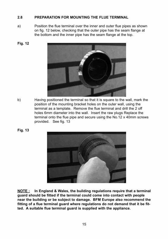
a) Position the flue terminal over the inner and outer flue pipes as shown on fig. 12 below, checking that the outer pipe has the seam flange at the bottom and the inner pipe has the seam flange at the top.
Fig. 12
b) Having positioned the terminal so that it is square to the wall, mark the position of the mounting bracket holes on the outer wall, using the terminal as a template. Remove the flue terminal and drill the 2 off holes 6mm diameter into the wall. Insert the raw plugs Replace the terminal onto the flue pipe and secure using the No.12 x 40mm screws provided. See fig. 13
Fig. 13
NOTE : In England & Wales, the building regulations require that a terminalguard should be fitted if the terminal could come into contact with peoplenear the building or be subject to damage. BFM Europe also recommend thefitting of a flue terminal guard where regulations do not demand that it be fit-ted. A suitable flue terminal guard is supplied with the appliance.
15
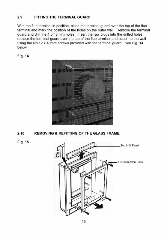
2.9 FITTING THE TERMINAL GUARD
With the flue terminal in position, place the terminal guard over the top of the flueterminal and mark the position of the holes on the outer wall. Remove the terminalguard and drill the 4 off 6 mm holes. Insert the raw plugs into the drilled holes,replace the terminal guard over the top of the flue terminal and attach to the wallusing the No.12 x 40mm screws provided with the terminal guard. See Fig. 14below.
Fig. 14
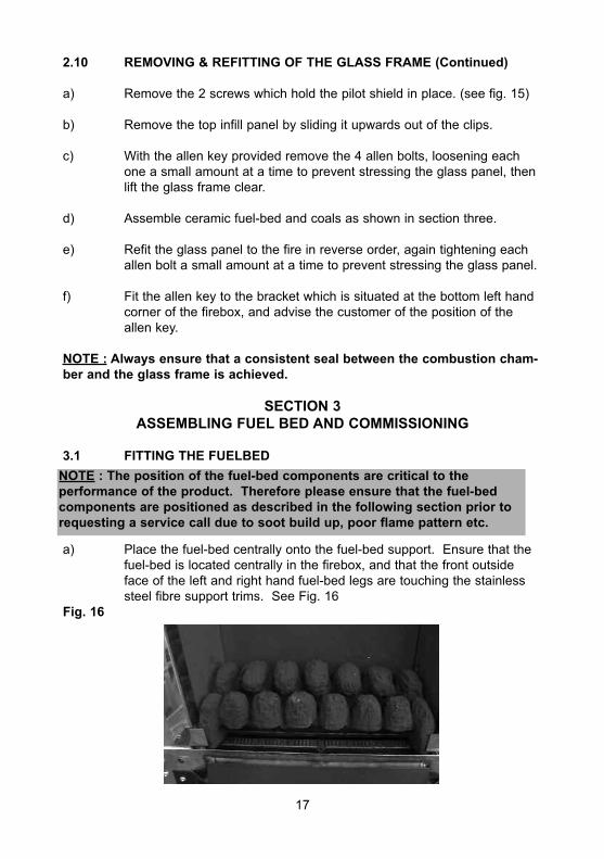
2.10 REMOVING & REFITTING OF THE GLASS FRAME.
Fig. 15
16
Top Infill Panel
4 x 6mm Allen Bolts
2.10 REMOVING & REFITTING OF THE GLASS FRAME (Continued)
a) Remove the 2 screws which hold the pilot shield in place. (see fig. 15)
b) Remove the top infill panel by sliding it upwards out of the clips.
c) With the allen key provided remove the 4 allen bolts, loosening each one a small amount at a time to prevent stressing the glass panel, then lift the glass frame clear.
d) Assemble ceramic fuel-bed and coals as shown in section three.
e) Refit the glass panel to the fire in reverse order, again tightening each allen bolt a small amount at a time to prevent stressing the glass panel.
f) Fit the allen key to the bracket which is situated at the bottom left hand corner of the firebox, and advise the customer of the position of the allen key.
NOTE : Always ensure that a consistent seal between the combustion cham-ber and the glass frame is achieved.
SECTION 3ASSEMBLING FUEL BED AND COMMISSIONING
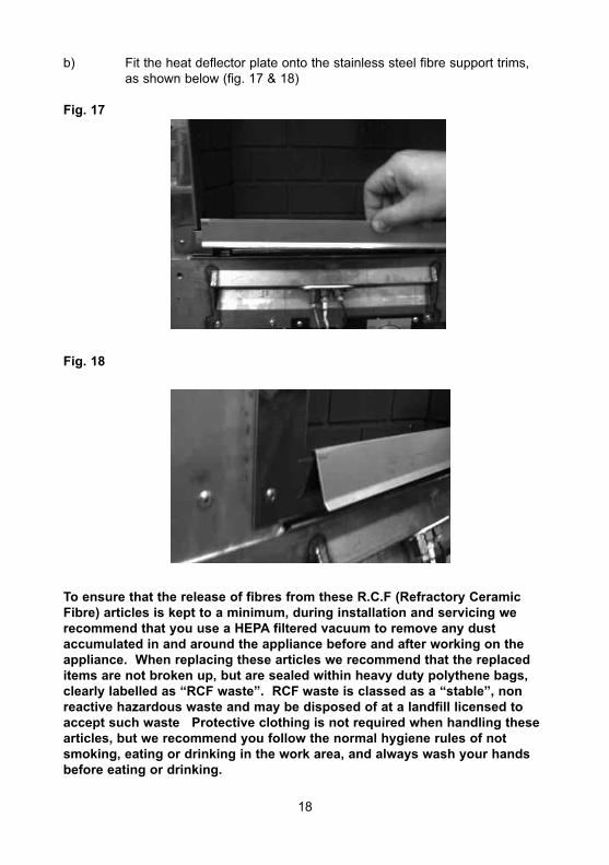
3.1 FITTING THE FUELBED
a) Place the fuel-bed centrally onto the fuel-bed support. Ensure that the fuel-bed is located centrally in the firebox, and that the front outside face of the left and right hand fuel-bed legs are touching the stainless steel fibre support trims. See Fig. 16
Fig. 16
17
NOTE : The position of the fuel-bed components are critical to the performance of the product. Therefore please ensure that the fuel-bed components are positioned as described in the following section prior torequesting a service call due to soot build up, poor flame pattern etc.
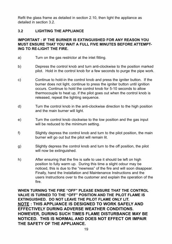
b) Fit the heat deflector plate onto the stainless steel fibre support trims, as shown below (fig. 17 & 18)
Fig. 17
Fig. 18
To ensure that the release of fibres from these R.C.F (Refractory CeramicFibre) articles is kept to a minimum, during installation and servicing we recommend that you use a HEPA filtered vacuum to remove any dust accumulated in and around the appliance before and after working on the appliance. When replacing these articles we recommend that the replaceditems are not broken up, but are sealed within heavy duty polythene bags,clearly labelled as “RCF waste”. RCF waste is classed as a “stable”, nonreactive hazardous waste and may be disposed of at a landfill licensed toaccept such waste Protective clothing is not required when handling thesearticles, but we recommend you follow the normal hygiene rules of notsmoking, eating or drinking in the work area, and always wash your handsbefore eating or drinking.
18
Refit the glass frame as detailed in section 2.10, then light the appliance asdetailed in section 3.2.
3.2 LIGHTING THE APPLIANCE
IMPORTANT : IF THE BURNER IS EXTINGUISHED FOR ANY REASON YOUMUST ENSURE THAT YOU WAIT A FULL FIVE MINUTES BEFORE ATTEMPT-ING TO RE-LIGHT THE FIRE.
a) Turn on the gas restrictor at the inlet fitting.
b) Depress the control knob and turn anti-clockwise to the position markedpilot. Hold in the control knob for a few seconds to purge the pipe work.
c) Continue to hold-in the control knob and press the igniter button. If the burner does not light, continue to press the igniter button until ignition occurs. Continue to hold the control knob for 5-10 seconds to allow thermocouple to heat up, if the pilot goes out when the control knob is released, repeat the lighting sequence.
d) Turn the control knob in the anti-clockwise direction to the high position and the main burner will light.
e) Turn the control knob clockwise to the low position and the gas input will be reduced to the minimum setting.
f) Slightly depress the control knob and turn to the pilot position, the main burner will go out but the pilot will remain lit.
g) Slightly depress the control knob and turn to the off position, the pilot will now be extinguished.
h) After ensuring that the fire is safe to use it should be left on high position to fully warm up. During this time a slight odour may be noticed, this is due to the “newness” of the fire and will soon disappear.Finally, hand the Installation and Maintenance Instructions and the users Instructions over to the customer and explain the operation of the fire.
WHEN TURNING THE FIRE “OFF” PLEASE ENSURE THAT THE CONTROLVALVE IS TURNED TO THE “OFF” POSITION AND THE PILOT FLAME ISEXTINGUISHED. DO NOT LEAVE THE PILOT FLAME ONLY LIT.NOTE : THIS APPLIANCE IS DESIGNED TO WORK SAFELY AND EFFECTIVELY DURING ADVERSE WEATHER CONDITIONS. HOWEVER, DURING SUCH TIMES FLAME DISTURBANCE MAY BENOTICED. THIS IS NORMAL AND DOES NOT EFFECT OR IMPAIRTHE SAFETY OF THE APPLIANCE.
19
SECTION 4MAINTENANCE
Servicing Notes
Servicing should be carried out annually by a competent person such as aGAS SAFE registered engineer. It is a condition of Flavel Fires guaranteeschemes that this is carried out by a competent person i.e a GAS SAFE registered Engineer in accordance with these servicing notesThe condition of the coals should be checked and if necessary the whole setshould be replaced with a genuine replacement set.The burner assembly is designed to be removed as a complete unit for ease ofaccess. After any servicing work a gas tightness check must always be carried out.
4.1 Removing the burner assembly from the fire.
4.1.1 Remove Ash-pan, Fret assembly & Trim from the front of the fire.
4.1.2 Isolate the gas supply, remove the glass frame as shown on page 17, then remove the 2 off fixing screws which hold the pilot shield in place.
4.1.3 Loosen the pilot pipe, disconnect the ignition lead from the electrode and disconnect the thermocouple from the pilot assembly.
4.1.4 Remove the 12 off fixing screws which hold the pilot mounting panel & control panel in place.
4.1.5 Lift the pilot panel upwards and away from the pilot pipe, taking care notto damage or misplace the pilot injector, which is contained within the pilot body.
4.1.6 Loosen the burner pipe, which is situated below the burner to the left-hand-side, from the bulkhead fitting.
4.1.7 Remove the 4 off fixing screws which attach the burner to the firebox via fixing brackets.
4.2 Removing the Piezo Igniter
4.2.1 Remove Ashpan, Fret assembly & Trim from the front of the fire.
4.2.2 Isolate the gas supply, remove the glass frame, then remove the 2 off fixing screws which hold the pilot shield in place.
4.2.3 Disconnect the pipe to the bulkhead fitting, which is located to the left hand side of the convection air aperture.
20
4.2.4 Loosen the pilot pipe, disconnect the ignition lead from the electrode and disconnect the thermocouple from the pilot assembly.
4.2.5 Remove the 4 off fixing screws from the control panel.
4.2.6 Slide the control panel and gas train forwards, to the left.
4.2.7 Disconnect the ignition lead from the piezo and unscrew the retaining nut on the rear of the control panel. Withdraw the piezo from the front of the control panel. Re-assemble in reverse order and carry out a gas soundness test.
4.3 Removing the Control Valve from the fire.
4.3.1 Remove Ash-pan, Fret assembly & Trim from the front of the fire.
4.3.2 Isolate the gas supply, remove the glass frame, then remove the 2 off fixing screws which hold the pilot shield in place.
4.3.3 Disconnect the pipe to the bulkhead fitting, which is located to the left hand side of the convection air aperture.
4.3.4 Loosen the pilot pipe, disconnect the ignition lead from the electrode and disconnect the thermocouple from the pilot assembly.
4.3.5 Remove the 2 off fixing screws from the base of the control panel.
4.3.6 Slide the control panel and gas train forwards, to the left.
4.3.7 Loosen and remove the three gas pipe retaining nuts from the control valve and release the ends of the gas pipes from the control valve body.Loosen and remove the thermocouple securing nut from the end of the control tap.
4.3.8 Unscrew the control valve locknut from the front of the control panel andremove the control valve. We do not recommend re-greasing or servicing of control valves. Defective valves should be replaced with a genuine replacement of the correct type.
4.3.9 To refit a control tap, re-assemble in the reverse order noting that the control tap locates on a flat in the control panel. Carry out a gas tightness test after re-assembly.
4.4 Removing the Pilot Assembly
4.4.1 Remove Ash-pan, Fret assembly & Trim from the front of the fire.
4.4.2 Isolate the gas supply, remove the glass frame as shown on page 17, then remove the 2 off fixing screws which hold the pilot shield in place.
21
4.4.3 Loosen the pilot pipe, disconnect the ignition lead from the electrode, and remove the thermocouple from the pilot body.
4.4.4 Remove the two fixing screws which secure the pilot assembly to the pilot panel.
4.4.5 Remove the pilot assembly.
4.4.6 Re-assemble with an new pilot assembly, and gasket, ensuring than an even seal around the pilot assembly is obtained. Carry out a gas test after re-assembly.
Due to our policy of continual improvement and development the exactaccuracy of illustrations and descriptions contained in this book cannot beguaranteed
PARTS SHORTLIST
Replacement of parts must be carried out by a competent person such as a GASSAFE registered gas installer. The part numbers of the replaceable parts are asfollows, these are available from your local Flavel Stockist, whose details may befound on the BFM Europe website, address as shown on the back page of thisbook.
Gas Valve B-104440Piezo Igniter B-1320Ignition Wire B-14340Fuelbed 70-47800
Part No. B-1004443Issue 1
BFM Europe Ltd.Trentham LakesStoke-on-TrentStaffordshire
ST4 4TJ
www.bfm-europe.com
Telephone - General Enquiries : (01782) 339000Telephone - Service : (01782) 339008