radon construction principles and practices · radon construction principles and practices ... test...
TRANSCRIPT

RADON CONSTRUCTION
PRINCIPLES AND PRACTICES
Continuing Education Class for
Contractors and Building Department Personnel

RADON
IS
EVERYWHERE
Build Radon
Resistant and
Save Lives
Overview of radon
resistant construction
on a floating slab with
block foundation (left),
and a poured slab
(right).
I. AN OVERVIEW OF THE LAW RELATING TO
CONSTRUCTION IN RADON PRONE AREAS.
PART VII STANDARDS FOR RADON-RESISTANT BUILDINGS
553.98 Development of building codes for radon-resistant
buildings; funding; rules for radon-resistant passive
construction standards; ordinances.
(1) The department shall be provided funds for activities incidental to
the development and implementation of the building codes for radon-
resistant buildings and for such other building code-related activities
as directed by the Legislature.
(2) The rules for radon-resistant passive construction standards
proposed by the department for residential buildings are hereby
approved by the Legislature. The rules for radon-resistant
commercial building standards shall be submitted by the
department to the Legislature prior to becoming effective.

I. AN OVERVIEW OF THE LAW RELATING TO
CONSTRUCTION IN RADON PRONE AREAS.
553.98 (Continued)
(3) Local jurisdictions may enact ordinances for radon-resistant
building construction only pursuant to this subsection. A county
governing authority and the governing bodies of the municipalities
representing at least a majority of the county's municipal population
shall enter into an interlocal agreement to adopt by ordinance the
department's radon-resistant passive construction standards as a
code for residential radon-resistant building construction. The
standards shall apply uniformly to the entire jurisdictions that adopt
the standards. No local jurisdiction may adopt any requirement for
radon-resistant building construction other than the rules of the
department, nor enact any other requirements relating to
environmental radiation caused by the radon decay series
Other than the rules of the department.

II. WHAT IS RADON AND WHAT PROBLEMS
DOES IT CREATE?
What is Radon?
Radon is a naturally occurring radioactive gas that comes from
the decay of radium in the soil. Radon is a colorless, odorless,
tasteless, invisible and chemically inert gas. Radium is a decay
product of uranium. Uranium is present in almost all rocks and
soil and material derived from rocks.
What are problems are associated with exposure?
The Surgeon General has warned that radon is the second
leading cause of lung cancer in the United States.
U.S. SURGEON GENERAL HEALTH ADVISORY
“Indoor radon is the second-leading cause of lung cancer in the United
States and breathing it over prolonged periods can present a significant
health risk to families all over the country. It’s important to know that this
threat is completely preventable. Radon can be detected with a simple
test and fixed through well-established venting techniques.”

WHY IT’S IMPORTANT!
• Radon is a Class A carcinogen, known to cause lung cancer
in humans
• Second leading cause of lung cancer in the U.S
• Number one cause of lung cancer among non-smokers
• 21,000 annual deaths
• Radon induced Lung Cancer Mortality Costing $1.2
Billion/Year (1996 dollars)
• Indoor radon levels can be reduced
• Radon resistant construction will reduce indoor levels
• and minimize health risks

EPA GUIDANCE VS FLORIDA’S DATA
• EPA’s Action Level is 4 pCi/L.
• Florida’s highest officially recorded level was
267 pCi/L
PRINCIPLES OF OPERATION FOR FAN-POWERED SOIL
DEPRESSURIZATION RADON REDUCTION
From ASTM E 1465-08
Radon enters dwellings in a soil-gas that flows in through radon
entry pathways. The pathways are openings in foundation walls
and floors like cracks, utility penetrations, and floor-wall joints.
Other mechanisms for radon entry include diffusion and
emanation. Radon entry by diffusion, through apparently solid
materials, is rarely in amount and is ignored when designing and
installing soil depressurization radon reduction system. Another
extremely rare source of radon in emanation from building
material contains radium.

PRINCIPLES OF OPERATION FOR FAN-POWERED SOIL DEPRESSURIZATION RADON REDUCTION
From ASTM E 1465-08
Radon enters buildings because it is sucked in. In cool climates,
dwelling normally have a lower air pressure inside than outside;
basements and first floor of dwellings are said to have a negative
pressure (a lower pressure compared to the pressure outside the
building). Because of this negative pressure, radon, and soil-gas
are sucked into the dwelling. The negative pressure generally
increases in the winter causing buildings to suck in more radon in
the winter. The negative air pressures inside the building are
affected by temperature and humidly (indoors and outdoors), wind
speed and direction, air handling devices, which bring air into or
exhaust air from handling devices, which bring into or exhaust air
from the dwelling, and occupancy, for example, occupants’
living habits like leaving window open and thermostat.

PRINCIPLES OF OPERATION FOR FAN-POWERED SOIL DEPRESSURIZATION RADON REDUCTION
From ASTM E 1465-08
When a fan-powered soil depressurization radon system is
installed, one end of the radon system’s piping is connected to a
sealed gas-permeable layer of material just below the slab of the
dwelling; and other end is routed to a location outside the building
and above the roof where the soil-gas, containing radon can be
exhausted safely.
A radon fan (generally an in line tubular fan rated between 0 and
150 Watts) is installed in the radon system’s vent stack piping
(when radon test results indicated the need for radon reduction) as
a means of depressurizing the gas-permeable layer. The fan
should be located in unconditioned space which is above
occupiable space (if fan is installed inside).

Principles of Operation for Fan-Powered Soil Depressurization
Radon Reduction
From ASTM E 1465-08
If the soil between the footings of a dwelling is covered with a gas-
permeable layer with 25% or more void space, like crush stone, the
performance of soil depressurization system is signally enhanced.
Ideally , the footings would rest on undisturbed soil of low
permeably.
Turning on the radon system’s fan causes soil-gas to be removed
from the has the gas-permeable layer (and the soil below it) which
reduces the pressure under the building. When the pressure under
the building is lower than the pressure in it, soil-gas and radon no
longer flows into the building through the radon entry pathways
(cracks and openings in the foundation); instead air flows out of the
building through these pathways. The sub-slab depressurization
version of the fan-powered soil depressurization method reduces
indoor radon concentrations of 80 to 99%.

Why RRNC is Important!
• Depending on the area, 1-70% of
buildings tested have elevated radon.
• Data indicates that between 1 out of 5 and
1 out of 7 homes in Florida’s have a radon
problem.
• Elevated radon incidence rates - the same
in new and older homes.

Florida Data
Recent data shows 20% of residences have elevated radon levels.
8,256,847 Residences -> 1,651,369 w/elevated radon
18,089,888 People – Census 2000> 3,617,978 living with elevated radon
Historical data: approximately 14%
– 8,256,847 Residences -> 1,155,959 with elevated radon
– 18,089,888 People -> 2,532,584 living with elevated radon

Zip codes provide more specific information.
Radon on 23rd floor of condo
What Florida
Knows

Licensure or Certification
• Before CO:
Contractor is king. All work permitted under
contractor’s license
• After CO:
For work performed by contractor/builder or direct
employees as part of building sale with no
additional remuneration – no certification required
Any additional payments made for radon work or
payments made to third party (sub-contractor),
persons and business performing work shall be
certified by DOH for radon mitigation.

Florida Radon Protection Map

Florida Radon Protection Map
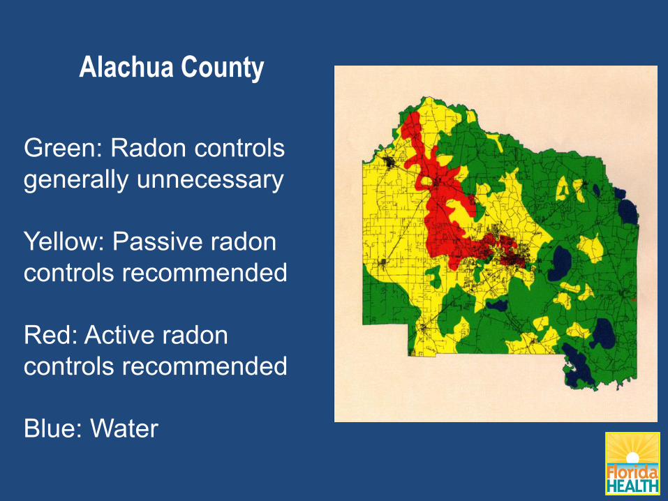
Alachua County

Polk County

Hillsborough County

Highlands County

III. Rules of the Department of Health Rules and
Florida Building Code
• Chapter 9B-52, Florida Standard for Passive
Radon-Resistant Construction (FBC, Appendix B)
• Chapter 9B-67, Florida Standard for Radon-
Resistant New Commercial Building Construction
(FBC, Appendix E)

III. Rules of the Department of Health Rules and
Florida Building Code
• Chapter 9B-52, Florida Standard for Passive
Radon-Resistant Construction (FBC, Appendix B)
• Chapter 9B-67, Florida Standard for Radon-
Resistant New Commercial Building Construction
(FBC, Appendix E)

FLORIDA BUILDING
CODE APPENDIX B
CHAPTER 9B-52 FLORIDA STANDARD FOR PASSIVE RADON-
RESISTANT CONSTRUCTION NEW RESIDENTIAL BUILDING
CONSTRUCTION

FLORIDA BUILDING CODE APPENDIX B
CHAPTER 9B-52 FLORIDA STANDARD FOR PASSIVE RADON-RESISTANT
CONSTRUCTION NEW RESIDENTIAL BUILDING CONSTRUCTION
General. This standard shall apply to the design and construction of new residential buildings as determined in Section B103, for the control of human exposure to radon .
Applicability. This standard shall apply to the construction of new residential buildings and additions to existing residential buildings.
Additions. When the cost of an addition exceeds a cumulative total of 50 percent of the assessed value of the existing building, only the addition to the building must meet the requirements for new buildings.
Exemptions. Exempt buildings are as follows:
1. Buildings of classifications not listed B103.1, Applicability, and
2. Residential buildings built on piers or pilings that elevate the bottom of the floor joists a minimum of 18 inches above grade, do not have skirting or stem walls that restrict air ventilation, and comply with the following:
a. The perimeter of the building from the ground plane to the lower surface of the floor shall be totally open for ventilation, except when complying with item (c) below.
b. All pilings or other supports shall be solid, or if hollow, shall be capped by an 8 inch solid masonry unit or sealed by a permanent barrier that is impermeable to air flow.
c. Enclosures of any kind that connect between the soil and the structure shall be
sealed at the surface of the soil to comply with the sealing provisions of Chapter B3 and
shall have a soil contact area of less than 5 percent of the total building floor area.
B101

FLORIDA BUILDING CODE APPENDIX B
CHAPTER 9B-52 FLORIDA STANDARD FOR PASSIVE RADON-RESISTANT
CONSTRUCTION NEW RESIDENTIAL BUILDING CONSTRUCTION
CONSTRUCTION REQUIREMENTS FOR PASSIVE RADON
CONTROL
General. This chapter provides minimum design and construction criteria for
passive control of radon entry into residential buildings.
Membrane material. A sub-slab or soil-cover membrane shall consist of a
minimum 0.006 inch (6 mil) thick single layer of polyethylene. Polyvinylchloride
(PVC), or other nondeteriorating nonporous material provided the installed
thickness has greater or equal resistance to air flow, puncturing, cutting and
tearing, and a permeance of less than 0.3 perm in accordance with ASTM E 96.
Tape. Tape used to install the membrane shall have a minimum width of 2
inches and shall be pressure sensitive vinyl or other nondeteriorating pressure
sensitive tape compatible with the surfaces being joined.
Mastic. Mastic used to install the membrane shall be compatible with the
surfaces being joined, and shall be installed in accordance with the
manufacturer's recommendations.
Installation. The membrane shall be placed under the entire soil-contact
area of the floor in a manner that minimizes the required number of joints
and seams.
B301

FLORIDA BUILDING CODE APPENDIX B
CHAPTER 9B-52 FLORIDA STANDARD FOR PASSIVE RADON-RESISTANT
CONSTRUCTION NEW RESIDENTIAL BUILDING CONSTRUCTION
Seams. Seams between portions of the membrane shall be lapped a
minimum of 12 inches and shall be secured in place with a continuous
band of tape or mastic centered over the edge of the top membrane.
Slab edges and joints. The membrane shall fully cover the soil beneath
the building floor. Where the slab edge is cast against a foundation wall or
grade beam, the membrane shall contact the foundation element, and shall
not extend vertically into the slab more than one inch.
Penetrations, punctures, cuts and tears. At all points where pipes,
conduits, stakes, reinforcing bars or other objects pass through the
membrane, the membrane shall be fitted to within 1/2 inch of the
penetration and sealed to the penetration. Penetrations may be sealed
with either mastic or tape.
Repairs. Where portions of an existing slab have been removed and are
about to be replaced, a membrane shall be carefully fined to the opening
and all openings between the membrane and the soil closed with tape or
mastic.
B302

FLORIDA BUILDING CODE APPENDIX B
CHAPTER 9B-52 FLORIDA STANDARD FOR PASSIVE RADON-RESISTANT
CONSTRUCTION NEW RESIDENTIAL BUILDING CONSTRUCTION
Floor slab-on-grade buildings.
General. All concrete slabs supported on soil and used as floors for
conditioned space or enclosed spaces shall be constructed in accordance
with the provisions of Sections B302 and B303.
Slab edge detail. Slabs and
foundations shall be constructed using a
slab edge detail that eliminates cracks
that could connect the house interior to
subslab soil and is consistent with other
construction constraints such as terrain.
Monolithic slab construction should be
used where possible. Only the following
slab edge detail options may be used:
1. Thickened edge monolithic-The
subslab membrane shall extend beyond
the outside face of the slab edge.
Membrane Installation Monolithic Slab
B303.2

FLORIDA BUILDING CODE APPENDIX B
CHAPTER 9B-52 FLORIDA STANDARD FOR PASSIVE RADON-RESISTANT
CONSTRUCTION NEW RESIDENTIAL BUILDING CONSTRUCTION
2. Slab poured into stem wall-Where
concrete blocks are used as slab forms, the
subslab membrane shall extend horizontally
at least 1 inch into the stem wall, but shall
not extend upward along any vertical faces
of the stem wall. The concrete slab shall be
poured into the stem wall to completely fill
its volume to form a continuous and solid
stem wall cap of min. 8 inch thickness.
3. Slab capping stem wall-Where the floor
slab is formed and placed to completely
cover the stem wall, the subslab membrane
shall extend horizontally under the slab to its
outer edge. The supporting stem wall shall
be capped with a solid masonry unit of at
least 4 inch thickness beneath membrane
and the slab.
8” thick Masonry cap
Membrane used with
floating slab
B303.2

FLORIDA BUILDING CODE APPENDIX B
CHAPTER 9B-52 FLORIDA STANDARD FOR PASSIVE RADON-RESISTANT
CONSTRUCTION NEW RESIDENTIAL BUILDING CONSTRUCTION
Sealing of joints, penetrations and cracks in slabs.
Contraction joints. All contraction joints shall be cleaned and sealed
against soil-gas entry by use of an approved sealant applied according
to the manufacturer's instructions. For bottom-induced joints, inverted T-
split ribbed waterstops at least 6 inches wide made of impermeable
material may be formed into the slab and shall not require top-surface
sealing for radon control.
1. Clean crack
2. Seal with approved sealant. B303.3.1

FLORIDA BUILDING CODE APPENDIX B
CHAPTER 9B-52 FLORIDA STANDARD FOR PASSIVE RADON-RESISTANT
CONSTRUCTION NEW RESIDENTIAL BUILDING CONSTRUCTION
Sealing of joints, penetrations and cracks in slabs. (Continued)
Horizontal joints. Horizontal
joints between two slabs of
different elevations that are
poured at different times shall
provide horizontal contact
between the two slabs that is
at least 8 inches wide, or shall
be sealed by an approved
sealant.
Minimum 8” Lap
B303.3.2
Sealing Horizontal Joints or Lap Joints

FLORIDA BUILDING CODE APPENDIX B
CHAPTER 9B-52 FLORIDA STANDARD FOR PASSIVE RADON-RESISTANT
CONSTRUCTION NEW RESIDENTIAL BUILDING CONSTRUCTION
Vertical joints through slabs.
Vertical joints through slabs shall be
formed with a recess of not less than
1/4 inch by 1/4 inch and sealed with
an approved sealant.
Exception: Slabedge vertical joints
occurring in slab poured into stem
wall construction. The sealant shall
be applied according to the
manufacturer's instructions.
Sealant Min. ¼” x ¼”
B303.3.3
Sealing of joints, penetrations and cracks in slabs. (Continued)
Sealing Isolation Joints

FLORIDA BUILDING
CODE APPENDIX C
CHAPTER 9B-53 FLORIDA STANDARD FOR MITIGATION
OF RADON IN EXISTING BUILDINGS

FLORIDA BUILDING CODE APPENDIX C
CHAPTER 9B-53 FLORIDA STANDARD FOR MITIGATION OF RADON IN
EXISTING BUILDINGS
This building standard addresses five principal approaches to
mitigating radon accumulation in buildings:
1. Radon control using the building structure as a gas barrier. This is
a passive approach which requires no fans.
2. Radon control by lowering the air pressure in the soil beneath the
building relative to the indoor air pressure of the building. This is
an active approach which requires one or more electrically driven
fans.
3. Radon control by raising the indoor air pressure in the building
relative to the air pressure in the soil beneath the building. This is
an active approach which may either use an existing heating and
air-conditioning system blower or an additional electrically driven
fan. This approach may have significant negative impact on the annual energy consumption.

FLORIDA BUILDING CODE APPENDIX C
CHAPTER 9B-53 FLORIDA STANDARD FOR MITIGATION OF RADON IN
EXISTING BUILDINGS
4. Radon control by ventilating the building with outdoor air. This is an active approach which may either use an existing heating and air-conditioning system blower or an additional electrically driven fan. This approach may have significant negative impact on the annual energy consumption of the building due to heating and cooling of additional outdoor air and to increased fan power consumption.
5. Radon control by separating the building and source with a ventilated region of outside air. This approach is generally applicable to buildings with a crawl space, and may be either active or passive.
The standard does not mandate the implementation of any of the principal approaches listed above. It establishes minimum standard practices for each of the principal approaches. Implementation of these minimum standard practices does not guarantee successful mitigation. A post mitigation indoor radon concentration test must be conducted to demonstrate successful mitigation in compliance with the rules of the Department of Health and Chapter 3 of this standard.

FLORIDA BUILDING CODE APPENDIX C
CHAPTER 9B-53 FLORIDA STANDARD FOR MITIGATION OF
RADON IN EXISTING BUILDINGS
Chapter 4 Structural Sealing and HVAC Balancing
C402 - Sealing Cracks and joints in concrete floors.
C403 - Floors over Crawl space.
C404 - Combined construction types.
C405 - Approved sealing materials.
C406 - Space conditioning and ventilation systems.

FLORIDA BUILDING CODE APPENDIX C
CHAPTER 9B-53 FLORIDA STANDARD FOR MITIGATION OF RADON IN
EXISTING BUILDINGS
Small cracks and joints. Cracks and joints
less than 1/16 inch shall be sealed with an
elastomeric material.
Large cracks and joints. Where cracks are
larger than 1/16 inch they shall be enlarged
to ¼ inch by ¼ inch and sealed with an
approved caulk.
Utility penetrations in crawl space walls.
Utility penetrations or other openings
through hollow cavity walls that separate
conditioned space from soil, or conditioned
space from a crawl space, shall be sealed
with an approved material
Sealing Cracks and joints in concrete floors.
C402

FLORIDA BUILDING CODE APPENDIX C
CHAPTER 9B-53 FLORIDA STANDARD FOR MITIGATION OF RADON IN
EXISTING BUILDINGS
Hollow masonry walls. All
openings for electrical boxes and
plumbing or other wall penetrations
shall be sealed with an approved.
caulk or gasket.
Sumps. Any sump located in a
conditioned portion of a building, or
in an enclosed space directly
attached to a conditioned portion of
a building, shall be covered by a lid.
An air tight seal shall be formed
between the sump and lid and at
any wire or pipe penetrations.
C402

FLORIDA BUILDING CODE APPENDIX C
CHAPTER 9B-53 FLORIDA STANDARD FOR MITIGATION OF RADON IN
EXISTING BUILDINGS
Reinforced concrete floors. Cracks and penetrations through concrete floors constructed
over crawl spaces, and that are sealed in order to reduce radon entry.
Wood-framed floors. All penetrations through the subfloor, including plumbing pipes, wiring
and ductwork, shall be sealed with an approved caulks. Where large openings are created by
plumbing, such as at bath tub drains, sheet metal or other rigid and durable materials shall be
used in conjunction with sealants to seal the opening.
C403
Combined construction types.
Structural chases. Openings which connect a
crawl space and the space between floor or
ceiling joists, wall studs, or any other hollow
chase adjoining conditioned space, shall be
closed.
Wall penetrations. Openings for electrical or
plumbing connections in a wall between a
crawlspace and a conditioned space, shall be
closed and sealed with an approved caulk
and/or gasket.
Doors. When a door is located in a wall
between a crawlspace and the conditioned
space, it shall be fully weatherstripped or
gasketed. Sealing a Tub Set

FLORIDA BUILDING CODE APPENDIX C
CHAPTER 9B-53 FLORIDA STANDARD FOR MITIGATION OF RADON IN
EXISTING BUILDINGS
Approved sealant materials.
Sealants. Acceptable caulks and sealants shall conform with ASTM C 920-87,
Standard Specifications for Elastomeric Joint Sealants and ASTM C 962-86,
Standard Guide for Use of Elastomeric Joint Sealants.
Space conditioning and ventilation systems.
Mechanical system connections. Condensate drains and pipe chases for freon
lines that provide a direct connection between the indoor air and the soil shall be
sealed in accordance with the provisions of this section.
Condensate drains. Condensate drains shall connect to air outside the building
perimeter at a height of at least 6 inches above the finished grade ground level.
Chases through which the condensate and refrigerant lines run shall not terminate in
the air return plenum or duct.
Freon chases. Freon chases that terminate within the house or garage shall be
sealed with closed cell expanding foam material. Pipe insulation shall be removed
from the freon lines at the point of the seal to provide for complete bond between the
freon line and the foam.
C405
C406

FLORIDA BUILDING CODE APPENDIX C
CHAPTER 9B-53 FLORIDA STANDARD FOR MITIGATION OF RADON IN
EXISTING BUILDINGS
Air distribution systems.
Sealing. All ducts and plenums that are modified or sealed in order to achieve
acceptable indoor radon concentrations, shall be made airtight in accordance with
Chapter 13 of the Florida Building Code, Building. If ductboard is used, the seal
must be on the foil side of the ductboard. Mastic sealing systems designed
specifically for the conditions of use shall be used in accordance with the
manufacturer's recommendations to close and seal leaks in ducts or plenums.
Modifications to ducts located in crawlspaces or service areas of attics shall
incorporate support, cover or other protection from accidental damage.
Return plenums. If acceptable indoor radon concentrations are achieved in part by
construction or modification of a return plenum, it shall be constructed with materials
and closures which produce a continuous air barrier for the life of the building.
Construction of the return plenum shall be done such that a continuous air barrier
completely separates the plenum from adjacent building structures. If duct board is
the primary air barrier, then the joints shall be sealed by fabric and mastic.
C406.2

FLORIDA BUILDING CODE APPENDIX C
CHAPTER 9B-53 FLORIDA STANDARD FOR MITIGATION OF RADON IN
EXISTING BUILDINGS
ENGINEERED SYSTEMS
General. Design of radon mitigation systems must be signed by a certified radon
mitigation specialist. Additionally, for radon mitigation systems that rely upon
ventilation or pressurization of the conditioned space for radon control, the plans and
specifications for the ventilation or pressurization system shall be signed and where
appropriate sealed according to the provisions of §471.003, Florida Statutes and
§553.79, Florida Statutes. Such systems may include, but are not limited to, one of
the following:
Air pressure control. Indoor pressure may be elevated relative to subslab levels.
Ventilation. An indoor air exchange rate may be maintained in a sufficient quantity to
satisfy Section C502.1.
Compliance. Any engineered radon mitigation system in compliance with this
standard must maintain an indoor radon concentration equal to or less than the "not
to exceed" radon exposure standard established by the Florida Department of Health.
C501
C502

FLORIDA BUILDING CODE APPENDIX C
CHAPTER 9B-53 FLORIDA STANDARD FOR MITIGATION OF RADON IN
EXISTING BUILDINGS
SOIL DEPRESSURIZATION SYSTEMS
Fan. Suction shall be provided by a fan, rated
for continuous operation.
Location. The suction fan shall be located
where any leakage of air from the exhaust
portion of the fan or vent system shall be into
outside air.
Vents Material. Piping material shall be of
any type approved the Florida Building Code -
Plumbing for plumbing vents.
Slope. The vent piping shall have a minimum
slope of 1/8 inch per foot.
Terminals. Vent pipes shall be terminated in
locations that will minimize human exposure
to their exhaust air. Locations shall be above
the eave of the roof.
C602

FLORIDA BUILDING CODE APPENDIX C
CHAPTER 9B-53 FLORIDA STANDARD FOR MITIGATION OF RADON IN
EXISTING BUILDINGS
Subslab Depressurization Systems.
Depressurization systems in sands or
other granular soils shall as a minimum
and within the practical limits posed by
the building, meet the following requirements:
Arrangement. Within the practical limits
posed by the building, suction points shall
be distributed as nearly equally as
possible, and as follows:
A maximum of 1,300 square feet per
suction point, and each required suction
point shall be located not less than 6 feet
nor more than 18 feet from the perimeter
C603
Suction Pit

FLORIDA BUILDING CODE APPENDIX C
CHAPTER 9B-53 FLORIDA STANDARD FOR MITIGATION OF RADON IN
EXISTING BUILDINGS
Subslab depressurization systems.
Pipe size. Suction pipe should be of a size appropriate to the air-flows of
the system, a minimum of 1.5 inches in diameter at the fan, and shall not
be reduced between the fan outlet and the final termination point.
Pits. Suction point pits excavated
below the slab shall be sized to
provide adequate pressure distribution
beneath the slab. Dimensions of 22
inches in diameter and 11 inches
deep, or excavation of 1 cubic foot of
soil, shall be presumed to meet this
requirement. Further the pit shall be
filled with 1-inch size gravel.
Rating. Suction fans must be capable of developing minimum
flows appropriate to the system at 1-inch water column pressure.
C603.1
FLORIDA BUILDING CODE APPENDIX C
CHAPTER 9B-53 FLORIDA STANDARD FOR MITIGATION OF RADON IN
EXISTING BUILDINGS
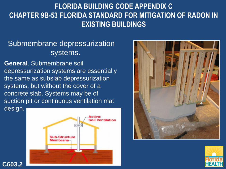
Submembrane depressurization
systems.
General. Submembrane soil
depressurization systems are essentially
the same as subslab depressurization
systems, but without the cover of a
concrete slab. Systems may be of
suction pit or continuous ventilation mat
design.
C603.2

FLORIDA BUILDING CODE APPENDIX C
CHAPTER 9B-53 FLORIDA STANDARD FOR MITIGATION OF RADON IN
EXISTING BUILDINGS
Submembrane depressurization systems.
Membrane soilgas retarder. A membrane
soilgas retarder shall consist of a 8 mil or thicker
polyethylene sheet . Place sheeting to minimize
seams and to cover all of the soil below the
building floor. Retarders must provide excellent
environmental stress crack resistance, impact
strength and high tensile strength including
additives to retard polymer oxidation and UV
degradation. Where pipes, columns or other
objects penetrate the soil-gas retarder, it shall be
cut and sealed to the pipe, column or penetration.
All seams of the membrane shall be lapped at
least 12 inches. Punctures or tears in the
membrane shall be repaired with the same or compatible material.
C603.2

FLORIDA BUILDING CODE APPENDIX C
CHAPTER 9B-53 FLORIDA STANDARD FOR MITIGATION OF RADON IN
EXISTING BUILDINGS
Submembrane depressurization systems.
Depressurization systems in sands or granular soils with suction pit
design. Submembrane soil depressurization systems covering sand or
other granular soils with the suction pits filled with 1-inch size gravel which
shall be covered by 1/8-inch thick steel plate, 16 gage corrugated sheet
metal, or equivalent sheets of other termite resistant structural materials.
Depressurization systems in sands or granular soils with continuous
ventilation mat(s) design. Systems in sands or other granular soils and
utilizing a continuous ventilation mat shall have at least 216 square inches
of suction area per lineal foot and shall meet the following requirements:
C603.2.1
FLORIDA BUILDING CODE APPENDIX C
CHAPTER 9B-53 FLORIDA STANDARD FOR MITIGATION OF RADON IN
EXISTING BUILDINGS
Submembrane depressurization systems.
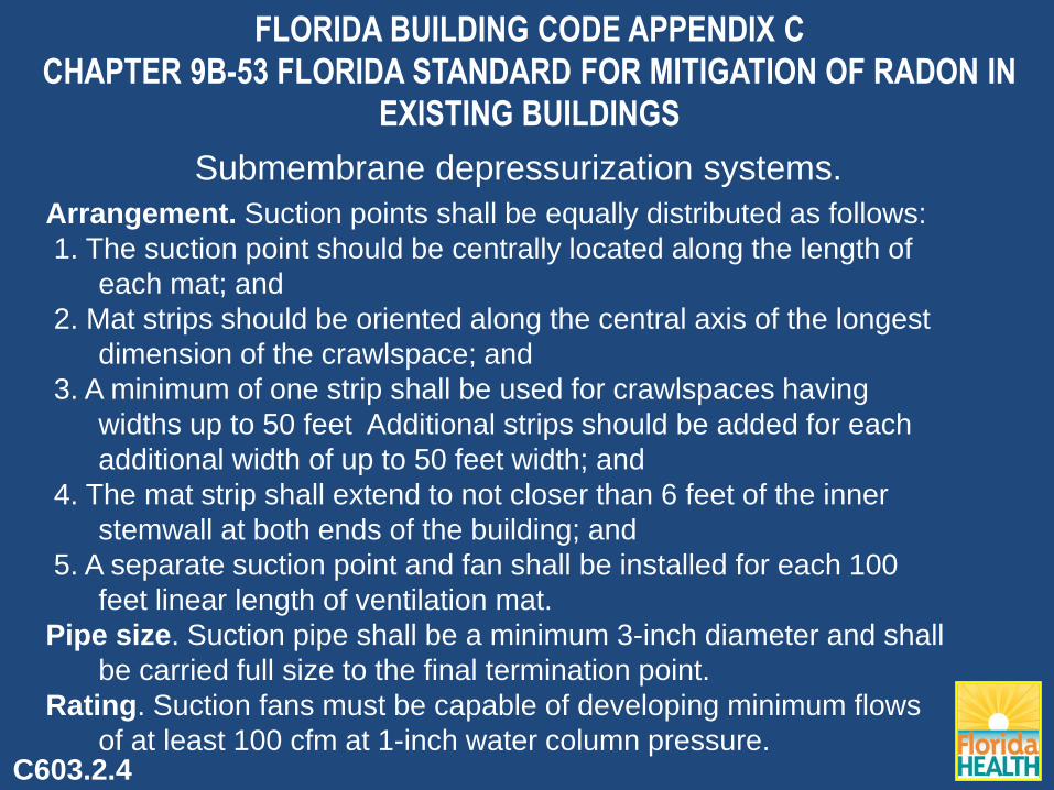
Arrangement. Suction points shall be equally distributed as follows:
1. The suction point should be centrally located along the length of
each mat; and
2. Mat strips should be oriented along the central axis of the longest
dimension of the crawlspace; and
3. A minimum of one strip shall be used for crawlspaces having
widths up to 50 feet Additional strips should be added for each
additional width of up to 50 feet width; and
4. The mat strip shall extend to not closer than 6 feet of the inner
stemwall at both ends of the building; and
5. A separate suction point and fan shall be installed for each 100
feet linear length of ventilation mat.
Pipe size. Suction pipe shall be a minimum 3-inch diameter and shall
be carried full size to the final termination point.
Rating. Suction fans must be capable of developing minimum flows
of at least 100 cfm at 1-inch water column pressure. C603.2.4

FLORIDA BUILDING
CODE
APPENDIX E
Chapter 9 B-67 FLORIDA STANDARD FOR RADON-RESISTANT
NEW COMMERCIAL CONSTRUCTION

FLORIDA BUILDING CODE APPENDIX E
Chapter 9 B-67 FLORIDA STANDARD FOR RADON-RESISTANT NEW
COMMERCIAL CONSTRUCTION
General. The design and construction requirements set forth in the
following chapters and sections shall constitute and be known as the
Florida Standard For Radon-Resistant Commercial Building
Construction, hereinafter referred to as "this standard.“
Intent. This standard was developed in accordance with Section
553.98, Florida Statutes, to minimize radon entry into newly
constructed commercial buildings, in compliance with the state health
standard. The design, construction, and operation of buildings are
governed by a variety of codes, standards, guidelines, and regulations.
Nothing in this standard is intended to create a conflict with existing
health and life-safety regulations.
E101
E102

FLORIDA BUILDING CODE APPENDIX E
Chapter 9 B-67 FLORIDA STANDARD FOR RADON-RESISTANT NEW
COMMERCIAL CONSTRUCTION
Applicability. The provisions of this standard shall apply to the design
and construction of new commercial buildings and additions to existing
commercial buildings, except single family and multiple-family
residential buildings of three or fewer stories above grade and those
identified in Section E104.3. When adopted by county and local
government, this standard shall be applied uniformly countywide. This
standard shall not be modified by a local government or building-
regulatory agency.
Additions. When the cost of an addition to an existing building
exceeds 50 percent of the current value of the building; only the
addition must be brought into compliance with all applicable portions of
this standard, as defined in Section E104.
E103.1
E103.2

FLORIDA BUILDING CODE APPENDIX E
Chapter 9 B-67 FLORIDA STANDARD FOR RADON-RESISTANT NEW
COMMERCIAL CONSTRUCTION
General. Buildings designed and constructed in accordance with all the
applicable provisions of this standard are deemed to comply.
New buildings and additions. All new commercial buildings and
additions to existing buildings shall meet the following compliance
requirements of this standard:
1. Compliance with Florida Building Code – Existing and Chapter 13
of Florida Building Code, Building.
2. Use of methods described in Chapters 3 (Construction
Requirements for Passive Controls) and Chapter 4 (Active Soil-
Depressurization Systems) of this standard.
E104.1
E104.2

FLORIDA BUILDING CODE APPENDIX E
Chapter 9 B-67 FLORIDA STANDARD FOR RADON-RESISTANT NEW
COMMERCIAL CONSTRUCTION
Exemptions. All buildings described below in Items 1 through 5 are exempted from compliance with this standard.
1. Temporary structures.
2. Free-standing greenhouses used exclusively for the cultivation of live plants.
3. Open-air reviewing stands, grandstands and bleachers.
4. Farm structures used only for storage or to shelter animals.
5. Residential buildings defined as one- or two-family detached houses or townhouse apartments with no more than three stories.
Buildings described in Item 6 are exempted from compliance with Sections E306 and E307, and Chapter 4 of this standard.
6. Buildings of occupancy classification S, storage, or H, hazardous.
E104.3

FLORIDA BUILDING CODE APPENDIX E
Chapter 9 B-67 FLORIDA STANDARD FOR RADON-RESISTANT NEW
COMMERCIAL CONSTRUCTION
Exemptions (Continued). Elevated buildings that comply with all
provisions of Item 7 are exempted.
7. Elevated buildings that satisfy all the following conditions:
a. The structure shall be separated from the ground by a vertical separation,
measured between the final grade and the lower surface of the floor, of at
least 18 inches and
b. All pilings, posts, piers or other supports shall be solid, or if hollow, shall be
capped by a solid masonry unit or sealed at the surface of the soil with a
construction complying with all applicable portions of Chapter 3 of this
standard, and
c. Enclosures of any kind, including but not limited to chases, storage rooms,
elevator shafts and stairwells, that connect between the soil and the
structure, shall comply with all applicable provisions of Chapter 3 and shall
have a soil contact area of less than five percent (5 percent) of the
projected building floor area, and
d. The perimeter of the structure, from the ground plane to the lower surface
of the lowest floor shall be totally open for ventilation.
E104.3

FLORIDA BUILDING CODE APPENDIX E
Chapter 9 B-67 FLORIDA STANDARD FOR RADON-RESISTANT NEW
COMMERCIAL CONSTRUCTION
Required documentation. In order to comply with this standard, all
structures must include in the construction documents provided for
permitting, a summary of the radon-resistant design strategies being
implemented in the structure.
Additionally, the building owner shall be provided with a manual
substantiating the radon resistance features.
This manual shall include:
1. A summary of the radon-resistant design strategies incorporated
into the structure,
2. A listing of the design specifications for all relevant motor-driven
systems;
3. A maintenance schedule for maintaining design specifications,
including active soil depressurization and heating, ventilating, and
air conditioning systems; and
4. A listing of all critical adjustments, such as intake-air damper
settings.
E104.4

FLORIDA BUILDING CODE APPENDIX E
Chapter 9 B-67 FLORIDA STANDARD FOR RADON-RESISTANT NEW
COMMERCIAL CONSTRUCTION
General. A soil-depressurization system
maintains a lower air pressure in the soil
directly beneath the building floor and
foundation than exists within the building.
This not only draws radon away, but also
causes the direction of the airflow through
any possible failure in the structural barrier
to be out of the building and into the soil-
depressurization system. Soil
depressurization systems may be installed
beneath concrete slabs supported directly
on the soil, or beneath the soil-gas-
retarder membrane in crawl spaces.
ACTIVE SOIL-DEPRESSURIZATION SYSTEMS (ASD)
E401

FLORIDA BUILDING CODE APPENDIX E
Chapter 9 B-67 FLORIDA STANDARD FOR RADON-RESISTANT NEW
COMMERCIAL CONSTRUCTION
Prohibited uses. Soil-depressurization systems components may not
extend beneath areas that are required to be depressurized by other
codes for the protection of public health, for example rooms containing
general anesthesia, pathogens, or poisonous chemicals. Soil
depressurization systems may be installed beneath rooms that are
required to be depressurized for other reasons, such as toilets and
kitchens.
System components. An active soil-depressurization (ASD) system is
comprised of the following components: pressure distribution system
porous media or manifolds; a soil cover; one or more vents; a suction
fan; and a system failure indicator.
ACTIVE SOIL-DEPRESSURIZATION SYSTEMS (ASD)
E401.1
E402

FLORIDA BUILDING CODE APPENDIX E
Chapter 9 B-67 FLORIDA STANDARD FOR RADON-RESISTANT NEW
COMMERCIAL CONSTRUCTION
Pressure distribution media or manifolds. A wide variety of means can
be utilized to extend the low-pressure zone across the entire area
beneath the structure.
1. Ventilation mats shall have a soil contact area of at least 216 square
inches per lineal foot and provide a cross-section profile of at least 9
square inches.
2. Perforated pipe may be used to construct pressure extension
manifolds. These pipes may be installed directly under the soil cover
or in gravel or a similar porous medium that provides an adequate
airflow connection between the pipe and the subsoil and that protects
the pipe from becoming blocked by soil.
3. Continuous gravel layers of at least 4 inches thick are an acceptable
pressure distribution medium, provided they completely cover the
area of soil to be depressurized.
ACTIVE SOIL-DEPRESSURIZATION SYSTEMS (ASD)
E402.1

FLORIDA BUILDING CODE APPENDIX E
Chapter 9 B-67 FLORIDA STANDARD FOR RADON-RESISTANT NEW
COMMERCIAL CONSTRUCTION
Soil cover. In slab-on-grade construction, the soil cover consists of the soil-gas-retarder membrane and the concrete slab. If a crawl spaces has a soil-gas-retarder membrane concrete may be omitted. In all instances, the soil-gas-retarder membrane shall be fully sealed to the radon vents in accordance with the provisions of Section E302.
Radon vents. Radon vents are gas-tight pipes that carry the soil-gas to an area above and away from the building.
Suction fans. Suction fans shall be designed for continuous operation to create a pressure difference between the subslab and the indoors.
Fan-failure indicator. Each system shall have a failure indicator labeled with the words "RADON REDUCTION SYSTEM FAN FAILURE INDICATOR" mounted so as to be visible to the building occupants.
ACTIVE SOIL-DEPRESSURIZATION SYSTEMS (ASD)
E402.2
E402.3
E402.4
E402.5

FLORIDA BUILDING CODE APPENDIX E
Chapter 9 B-67 FLORIDA STANDARD FOR RADON-RESISTANT NEW
COMMERCIAL CONSTRUCTION
ASD system design requirements. (Continued)
General. All ASD systems must comply with a design shown by the large-
building active soil-depressurization model to be capable of maintaining a 0.02-
inch (5 Pascal) pressure differential over 90 percent of the slab or crawlspace
area.
Ventilation mat systems. Mat systems
may be designed and installed in
accordance with a design shown by the
large-building active soil-depressurization
model to be capable of maintaining a 5
Pascal pressure differential over 90
percent of the slab area or with Section
503.2.2.
Installation. Radon ventilation mats shall
be installed immediately prior to placing
the soil-gas-retarder membrane, to reduce
the chance for soil to enter and block the
mat. E403

FLORIDA BUILDING CODE APPENDIX E
Chapter 9 B-67 FLORIDA STANDARD FOR RADON-RESISTANT NEW
COMMERCIAL CONSTRUCTION
ASD system design requirements.
Perforated pipe systems. Perforated pipes shall be of a material approved by
the governing building code for foundation drainage, and sized according to the
air-flow estimated from the large-building active soil-depressurization model.
Where perforated pipes are installed in gravel meeting ASTM D 448, numbers 4 or
5 gravel, with not more than 5 percent passing a 3/8 inch screen.
E403
Perforated Pipe System

FLORIDA BUILDING CODE APPENDIX E
Chapter 9 B-67 FLORIDA STANDARD FOR RADON-RESISTANT NEW
COMMERCIAL CONSTRUCTION
ASD system design requirements.
Perforated pipe systems. Perforated pipes shall be of a material approved by
the governing building code for foundation drainage, and sized according to the
air-flow estimated from the large-building active soil-depressurization model.
Where perforated pipes are installed in gravel meeting ASTM D 448, numbers 4 or
5 gravel, with not more than 5 percent passing a 3/8 inch screen.
Perforated Pipe System
E403

FLORIDA BUILDING CODE APPENDIX E
Chapter 9 B-67 FLORIDA STANDARD FOR RADON-RESISTANT NEW
COMMERCIAL CONSTRUCTION
ASD system design requirements. (Continued)
Installation. Perforated pipe pressure distribution manifolds shall be installed only after the installation of all other utilities has been completed, and immediately prior to the soil-gas-retarder membrane. Pipes shall be installed with a row of perforations located at the bottom of the pipe. Pipes shall be arranged in a pattern that provides at least two possible flow paths from any point in the system to a radon vent pipe.
Radon vent connection. The radon vent pipe shall join to the perforated pipe with a fitting that allows for the fill air-flow capacity of the vent pipe.
Continuous gravel layer systems. Gravel used as the pressure distribution medium shall be installed only after the installation of all other utilities has been completed, and immediately prior to the soil-gas-retarder membrane. The size and number of such pipes shall be sufficient to provide at least two-times the anticipated air-flow. In no case shall fewer than two pipes be used to interconnect one gravel area with another. These pipes shall be separated by a horizontal distance not less than one-half the length of the boundary between the connecting gravel areas.
E403

FLORIDA BUILDING CODE APPENDIX E
Chapter 9 B-67 FLORIDA STANDARD FOR RADON-RESISTANT NEW
COMMERCIAL CONSTRUCTION
ASD system design requirements. (Continued)
Radon vent connection. The radon vent pipe shall join to the gravel layer with a "T" fitting that allows for the full airflow capacity of the vent pipe from either side of the "T." The fitting shall be installed with two arms in the gravel and a single arm connected to the radon vent pipe
Radon vent pipe installation. Radon vent pipes shall be solvent welded or otherwise joined to create a gas-tight connection from the soil-suction point to the vent termination point.
E403

FLORIDA BUILDING CODE APPENDIX E
Chapter 9 B-67 FLORIDA STANDARD FOR RADON-RESISTANT NEW
COMMERCIAL CONSTRUCTION
ASD system design requirements. (Continued)
Labeling. All portions of the radon vent pipe not permanently encased in a wall or chase shall be labeled to prevent accidental misuse. Labels shall consist of a pressure sensitive 2 inch yellow band with the words
“Radon Reduction System" printed in black letters at least 1 inch in height. These labels shall be placed on every visible portion of the vent pipe at a spacing of not more than 3 feet.
The size of vent pipes shall be determined based on air-flow rates predicted with the large-building active soil-depressurization model. For systems that comply with the alternate compliance method, Section E403.2.2, and are installed in buildings with straight runs of vent pipes no more than 50 ft. in height the required number and size of vent pipes may be determined as follows:
1. For up to 100 linear ft. of vent. mat use 1-2” dia. pipe.
2. For up to 200 linear ft. of vent. mat use 1-3” dia. pipe, or 2-2” dia. pipes.
3. For up to 400 linear feet of ventilation mat use one 4-inch diameter pipe, or 2-3” dia. pipes, or 4-2” dia. pipes.
E403.5.1
FLORIDA BUILDING CODE APPENDIX E
Chapter 9 B-67 FLORIDA STANDARD FOR RADON-RESISTANT NEW
COMMERCIAL CONSTRUCTION
ASD system design requirements. (Continued)
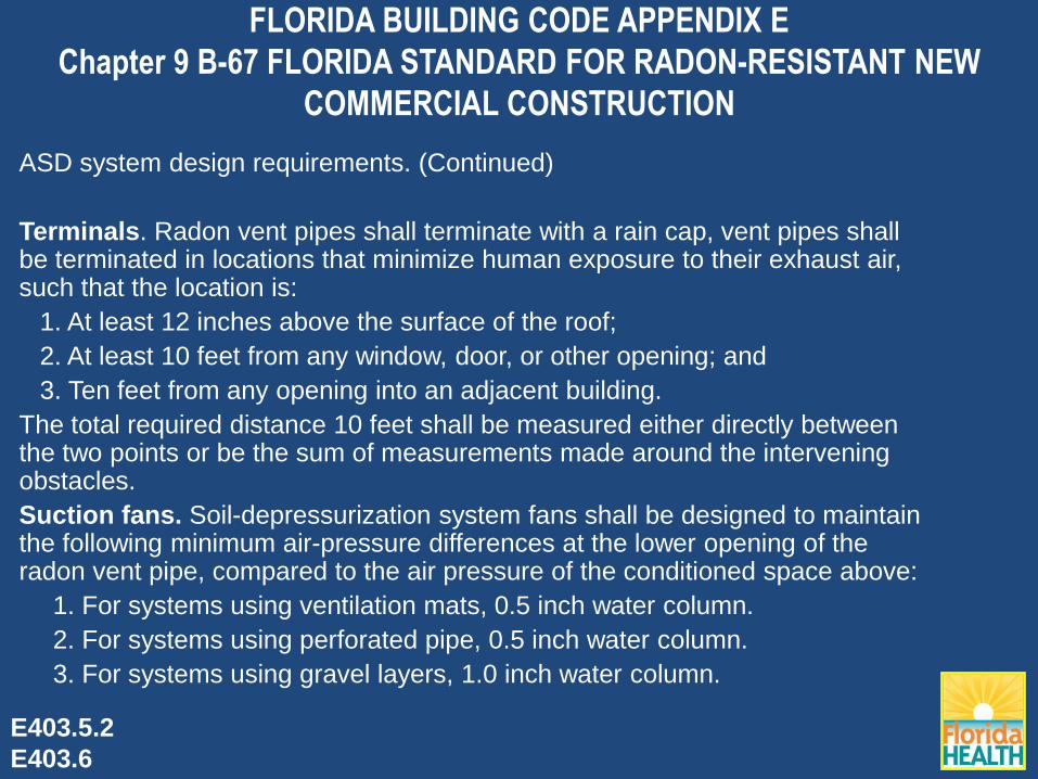
Terminals. Radon vent pipes shall terminate with a rain cap, vent pipes shall be terminated in locations that minimize human exposure to their exhaust air, such that the location is:
1. At least 12 inches above the surface of the roof;
2. At least 10 feet from any window, door, or other opening; and
3. Ten feet from any opening into an adjacent building.
The total required distance 10 feet shall be measured either directly between the two points or be the sum of measurements made around the intervening obstacles.
Suction fans. Soil-depressurization system fans shall be designed to maintain the following minimum air-pressure differences at the lower opening of the radon vent pipe, compared to the air pressure of the conditioned space above:
1. For systems using ventilation mats, 0.5 inch water column.
2. For systems using perforated pipe, 0.5 inch water column.
3. For systems using gravel layers, 1.0 inch water column.
E403.5.2
E403.6

FLORIDA BUILDING CODE APPENDIX E
Chapter 9 B-67 FLORIDA STANDARD FOR RADON-RESISTANT NEW
COMMERCIAL CONSTRUCTION
ASD system design requirements. (Continued)
Fan sizing. Soil-depressurization systems that comply with the
alternative compliance method, Section E403.2.2, and sizing, Section
E403.5.2, may comply by sizing the fan as follows:
1. For up to 100 lineal feet of ventilation mat the fan shall be rated for
50 cfm at 1-inch water column.
2. For 100 to 200 lineal feet of ventilation mat, the fan shall be rated
for at least 100 cfm at 1-inch water column.
3. For 200 to 400 lineal feet of ventilation mat, the fan shall be rated
for at least 175 cfm at 1-inch water column.
E403.6.1

Questions and Answers
RADON CONSTRUCTION
PRINCIPLES AND PRACTICES
ASTM-E1465-08a
Standard Practice for Radon Control Options for the Design
and Construction of New Low-Rise Residential Buildings.
Abstract
This practice provides the design details and construction methods for two
built-in soil depressurization radon control and reduction systems
appropriate for use in new low-rise residential buildings. Depending on the
configuration of the radon vent stack installed, the radon system's
operation may have a pipe route appropriate for a fan-powered radon
reduction system, or have a more efficient pipe route appropriate for
passively operated radon reduction systems. This practice covers special
features for soil depressurization radon reduction systems including (1)
slab-on-grade, basement and crawlspace foundation types with cast
concrete slab and membrane ground covers, (2) sub-slab and
submembrane gas-permeable layers and their drainage, (3) radon system
piping, (4) radon discharge separation from openings into occupiable
space, (5) radon fan installation, (6) electrical requirements, (7) radon
system monitor installation, (8) labeling, (9) radon testing, and
(10) system documentation.
ASTM-E1465-08a
Standard Practice for Radon Control Options for the Design
and Construction of New Low-Rise Residential Buildings.
Abstract (Continued)
This abstract is a brief summary of the referenced standard. It is informational only and not an official part of the standard; the full text of the standard itself must be referred to for its use and application. ASTM does not give any warranty express or implied or make any representation that the contents of this abstract are accurate, complete or up to date.

ASTM-E1465-08a Significance and Use
Fan-powered radon reduction systems built into new residential buildings
according to this practice are likely to reduce elevated indoor radon levels,
where soil-gas is the source of radon, to below 2.0 picocuries per litre
(pCi/L) in occupiable spaces. Passive radon reduction systems do not
always reduce such indoor radon concentrations to below 2.0 picocuries
per litre (pCi/L) in occupiable spaces. When a passive system, built
according to this practice, does not achieve acceptable radon
concentrations, that system should be converted to fan-powered operation
to significantly improve its performance.
Exceptions—New residential buildings built on expansive soil and karst
may require additional measures, not included in this practice, to achieve
acceptable radon reduction. Consider consulting with a soil/geotechnical
specialist, a qualified foundation structural engineer and contacting the
state’s radon in air specialist for up-to-date information about construction
methods. Names of your state radon specialist are available from the U.S.
EPA website .
http://www.epa.gov/radon
ASTM-E1465-08a Significance and Use
Note 1—Residences using private wells can have elevated indoor radon
concentrations due to radon that out-gasses from the water used indoors,
like water used to shower (7). Consider contacting your state’s radon
specialist for up-to-date information on available methods for removing
radon from private well water.
All soil depressurization radon reduction methods require a gas-permeable
layer which can be depressurized. The gas-permeable layer is positioned
under the building’s sealed ground cover. In the case of the active soil
depressurization system, a radon fan pulls air up the vent stack to
depressurize the gas-permeable layer. In the case of a passive soil
depressurization system, when air in the vent stack is warmer than that
outdoors, the warmer air rises in the stack causing the gas-permeable layer
to be depressurized. The passive system depressurizes the gas-permeable
layer intermittently; the fan-powered system depressurizes the gas-
permeable layer continuously. The performance of gas-permeable layers
depends on their design; see 6.4.1.3. A radon reduction system that
operates passively requires the most efficient gas-permeable layer.

ASTM-E1465-08a
Significance and Use
The negotiated acceptable radon concentration defined by this standard can vary from customer to customer and contract to contract. The owner’s goal for radon reduction should be known and considered before the radon system design is specified. The construction choices for void space in the gas-permeable layer; vent stack pipe diameter and route; radon fan capacity; and building features influence the radon reduction system’s performance. (See 1.4, 3.2.1, 5.3, 5.4, 5.5, and 6.4.1.3.)
This practice offers organized information about radon reduction methods. This practice cannot replace education and experience and should be used in conjunction with trained and certified radon practitioner's judgment. Not all aspects of this practice may be applicable in all circumstances.

ASTM-E1465-08a Significance and Use
This practice is not intended, by itself, to replace the standard of
care by which adequacy of a professional service may be judged,
nor should this practice alone be applied without consideration of a
project's unique aspects.
The word “Standard” in the title of this practice means that the
document has been approved through the ASTM consensus
process.
Reliable methods for predicting indoor radon concentrations for a
particular residential building prior to its construction are not
available at this time. If the house is in contact with the ground, it is
possible for radon gas to be present. Not all houses will need a
radon system; nationally, 1 out of 15, or 7 % of the houses have
indoor radon concentrations greater than 4 pCi/L). In the highest
state 71 % of the houses have indoor radon greater than 4 pCi/L
more of the houses have indoor radon over 4 pCi/L.

ASTM-E1465-08a 1. Scope
1.1 This practice covers the design and construction of two radon
control options for use in new low-rise residential buildings. These
unobtrusive soil depressurization options are installed with a pipe
route appropriate for their intended initial mode of operation, that is,
fan-powered or passive. One of these pipe routes should be
installed during a residential building’s initial construction.
Specifications for the critical gas-permeable layer, the radon
system’s piping, and radon entry pathway reduction are
comprehensive and common to both pipe routes.
1.1.1 The first option has a pipe route appropriate for a fan-powered
radon reduction system. The radon fan should be installed after (1)
an initial radon test result reveals unacceptable radon
concentrations and therefore a need for an operating radon fan, or
(2) the owner has specified an operating radon fan, as well as
acceptable radon test results before occupancy.

ASTM-E1465-08a
1. Scope (Continued) 1.1.2 The second option has a more efficient pipe route appropriate for passively operated radon reduction systems. Passively operated radon reduction systems provide radon reductions of up to 50 %. When the radon test results for a building with an operating passive system are not acceptable, that system should be converted to fan-powered operation. Radon systems with pipe routes installed for passive operation can be converted easily to fan-powered operation; such fan operated systems reduce indoor radon concentrations up to 99 %.
1.3 Fan-powered, soil depressurization, radon-reduction techniques, such as those specified in this practice, have been used successfully for slab-on-grade, basement, and crawlspace foundations throughout the world.

ASTM-E1465-08a 1. Scope (Continued)
1.4 Radon in air testing is used to assure the
effectiveness of these soil depressurization radon
systems. The U.S. national goal for indoor radon
concentration, established by the U.S. Congress in the
1988 Indoor Radon Abatement Act, is to reduce indoor
radon as close to the levels of outside air as is
practicable. The radon concentration in outside air is
assumed to be 0.4 picocuries per litre (pCi/
l1.5 This practice is intended to assist owners, designers,
builders, building officials and others who design,
manage, and inspect radon systems and their
construction for new low-rise residential buildings.

ASTM-E1465-08a
1. Scope (Continued)
1.6 This practice can be used as a model set of practices,
which can be adopted or modified by state and local
jurisdictions, to fulfill objectives of their residential building
codes and regulations. This practice also can be used as a
reference for the federal, state, and local health officials and
radiation protection agencies.
1.7 The new dwelling units covered by this practice have
never been occupied. Radon reduction for existing low rise
residential buildings is covered by Practice E 2121, or by
state and local building codes and radiation protection
regulations.

ASTM-E1465-08a
1. Scope (Continued)
1.8 Fan-powered soil depressurization, the principal strategy
described in this practice, offers the most effective and most
reliable radon reduction of all currently available strategies.
Historically, far more fan-powered soil depressurization radon
reduction systems have been successfully installed and
operated than all other radon reduction methods combined.
These methods are not the only methods for reducing indoor
radon concentrations (1-3).
1.9 Section 7 is Occupational Radon Exposure and Worker
Safety.
1.10 Appendix X1 is Principles of Operation for Fan-Powered
Soil Depressurization Radon Reduction.

ASTM-E1465-08a
1. Scope
1.11 Appendix X2 is a Summary of Practice E 1465
Requirements for Installation of Radon Reduction Systems
in New Low Rise Residential Building.
1.12 The values stated in inch-pound units are to be
regarded as standard. The values given in parentheses are
mathematical conversions to SI units that are provided for
information only and are not considered standard.
1.13 This standard does not purport to address all of the
safety concerns, if any, associated with its use. It is the
responsibility of the user of this standard to establish
appropriate safety and health practices and determine the
applicability of regulatory limitations prior to use.