radiometric compensation for cooperative distributed multi...
TRANSCRIPT

Radiometric Compensation for Cooperative DistributedMulti-Projection System through 2-DOF Distributed Control
Jun Tsukamoto, Daisuke Iwai, and Kenji Kashima, Member, IEEE
Fig. 1. A projected result Y of the proposed radiometric compensation technique based on 2-DOF distributed control for the 76-thframe of the anial movie (see Section 5). To make the system scalable, a broadcasting from the camera node to the projector nodeswas only used as a communication method. Therefore, the input image to each projector xi was computed on each projector nodeusing a broadcasted data ξ from the camera node, which was computed with target image r and the previous projected result. Notethat some areas in the input images are masked for better visibility, where artifacts occur due to geometric calibration errors, whichdo not affect the projected result at all.
Abstract—This paper proposes a novel radiometric compensation technique for cooperative projection system based-on distributedoptimization. To achieve high scalability and robustness, we assume cooperative projection environments such that 1. each projectordoes not have information about other projectors as well as target images, 2. the camera does not have information about theprojectors either, while having the target images, and 3. only a broadcast communication from the camera to the projectors is allowedto suppress the data transfer bandwidth. To this end, we first investigate a distributed optimization based feedback mechanism thatis suitable for the required decentralized information processing environment. Next, we show that this mechanism works well for stillimage projection, however not necessary for moving images due to the lack of dynamic responsiveness. To overcome this issue,we propose to implement an additional feedforward mechanism. Such a 2 Degree Of Freedom (2-DOF) control structure is well-known in control engineering community as a typical method to enhance not only disturbance rejection but also reference trackingcapability, simultaneously. We theoretically guarantee and experimentally demonstrate that this 2-DOF structure yields the movingimage projection accuracy that is overwhelming the best achievable performance only by the distributed optimization mechanisms.
Index Terms—Projector-camera system, radiometric compensation, distributed optimization, control theory
1 INTRODUCTION
Radiometric compensation is an important fundamental technologyfor projection-based augmented reality (AR), which corrects color ar-tifacts of projected imagery on textured surfaces [7]. It has expandedthe application fields of projection-based AR by allowing not only sur-faces suitable for projections, such as uniformly white objects, butalmost arbitrary diffuse surfaces even with textures, to be projection
• Jun Tsukamoto is with Kyoto University. E-mail:[email protected].
• Daisuke Iwai is with Osaka University. E-mail:[email protected].
• Kenji Kashima is with Kyoto University. E-mail:[email protected].
targets. So far, much effort has been put on improving compensa-tion accuracy for a single projection system. However, due to variousfactors such as the limited dynamic ranges of projectors and shadowsof projected images, a single projection is not sufficient to provide ac-ceptable projection results in many application scenarios. In this paper,we focus on radiometric compensation for a cooperative overlappingmulti-projection system that has several advantages over a single pro-jection system, such as higher maximum luminance while coveringwider field of view and less shadows.
There are several technical issues for radiometric compensation ofa cooperative multi-projection system, which are not necessarily con-sidered in the previous researches for a single projection system. Forexample, the system should be scalable so that it accommodates thedemand of increasing computational costs and communications trafficwhen the number of projector nodes increases. In other words, it isimportant to have a Plug-and-Play capability by which a newly added(plug-in) projector node is automatically connected to the system’snetwork. The system also should be robust for the failure (plug-out)of projector nodes at runtime. However, these issues have not been

carefully considered in the radiometric compensation research field.To achieve high scalability, robustness and Plug-and-Play capabil-
ity as mentioned above, we propose to apply a distributed optimizationalgorithm based on distributed control theory to radiometric compen-sation for a cooperative overlapping projection system, rather than acentralized control approach in which a host node computes projectionimages for all projector nodes. Unique properties of our distributedprojection system consisting of a camera node and multiple projec-tor nodes are: (1) each projector node does not have any informationabout other projector nodes as well as target images, (2) the cameranode does not have any information about the projector nodes either,while having the target images, and (3) only a broadcast communica-tion from the camera node to the projector nodes is allowed to suppressthe data transfer bandwidth. A preliminary result suggests that a dis-tributed optimization algorithm based on feedback control potentiallyworks for the radiometric compensation in our distributed projectionsystem [20]. However, it practically requires tens of frames to con-verge, and consequently, works only for displaying static images.
In this paper, we propose a novel radiometric compensation tech-nique for our distributed projection system by combining the previ-ously proposed distributed optimization with centralized feedforwardmechanism while preserving the distributed feedback structure. Thenew technique improves the tracking responsiveness (i.e., speed ofconvergence) to realize the projections of radiometrically compensatedmoving images. Based on a control theoretic approach, we evaluatethe improvement through the comparison of error-to-reference ratiosin the frequency domain between the previous feedback-only and theproposed 2 degree of freedom (DOF) (i.e., feedback and feedforward)control designs. We also conduct real projection experiments to vali-date moving image qualities of compensated results.
To summarize, this paper makes the following contributions:
• We provide the theoretical performance limit of a distributed op-timization algorithm based on a feedback control for radiomet-ric compensation in terms of the tracking responsiveness using acontrol theoretic approach.
• We combine centralized feedforward mechanism with the dis-tributed optimization structure for improving the tracking re-sponsiveness to realize radiometric compensation of moving im-ages.
• Through real projection experiments, we show the feasibility ofthe proposed method for moving images, in terms of the com-pensation accuracy and the speed of convergence.
2 RELATED WORK
Radiometric compensation has been an active research topic inprojection-based AR. Most radiometric compensation techniques ap-ply a projector-camera system (procams) to compensate for projectedcolors disturbed by textures on projection surfaces. Bimber et al. pro-posed a simple linear model to describe the relationship between aninput pixel value to the projector of a procams and projected resultcaptured by a corresponding camera pixel [6]. Using the model, theycomputed an input image for the projector to display a target imageon arbitrary textured Lambertian surfaces. More complex but accu-rate models have been also proposed, such as one that considers thecrosstalk of color channels [23] and another that considers color valu-ation within a projector pixel area [14].
These compensation methods assume single projection systems. Onthe other hand, multi-projection systems are desirable in many ap-plication scenarios of projection-based AR, because they solve vari-ous inherent problems of single projection approach such as limitedmaximum intensity, defocus blur, and cast shadow [5, 15, 12]. Re-searchers also tried to solve the radiometric compensation issue inmulti-projection systems. Bimber et al. applied their method to amulti-projection system by evenly dividing target colors to all projec-tors [6]. Bermano et al. proposed more general method that computesa compensation image using a light transport matrix that describes arelationship between input pixel values for all pixels of all projectors
and the projected result [3]. Although these methods worked well,they heavily rely on a host computer that have centralized control overall projectors. Therefore, they are not suitable for our goal that isto realize a highly scalable, robust, and Plug-and-Play capable radio-metric compensation, as mentioned in the first section. Recently, itwas reported that projected results converged in a multiple overlappingprojection system by independently controlling them based on modelpredictive control theory [1, 2]. However, it was also pointed out thatthe technique did not accurately display target appearances because ofthe interference among projections, and it was not designed to displaymoving images.
In this paper, leveraging the recent rapid sophistication of dis-tributed control theory that is consequently expanding its applicationfields [13, 8], we build a radiometric compensation technique thatmeets our requirements (i.e, scalability, robustness, and Plug-and-Play capability) using a distributed optimization algorithm [16]. Wetheoretically guarantee the convergence of projected results to targetappearances by explicitly assuming dynamic interference of multipleoverlapping projections on a surface in stability analysis. Furthermore,to improve the speed of convergence of our distributed optimization,we combine a centralized feedforward mechanism to compensate formoving images, while preserving the distributed feedback structure.To the best of our knowledge, this is the first attempt to introduce dis-tributed optimization framework from distributed control theory forradiometric compensation of cooperative multi-projection system.
3 PROBLEM FORMULATION AND PREVIOUS WORK
This section describes the problem formulation of this researh andpreviously proposed radiometric compensation algorithm for our dis-tributed projection system [20]. We build our method based on theBimber’s linear model [6]. As with most of radiometric compensationmethods, we assume our projection objects as arbitrary shaped andtextured but limited to Lambertian surfaces.
3.1 System architecture and problem formulationWe consider a projector-camera system composed of n projector nodesand one camera node that is regarded as an eye of a human observer.Each projector node i has an input image x j
i ∈ [0,1] and form factorp j
i for the j-th pixel. Here, the form factor is the ratio of the pro-jected result image captured by the camera to the input image at eachpixel under completely dark environment. This is normally acquiredby projecting a uniform white image and capturing the reflection ona projection surface. This value is affected by the reflectance of thesurface, the distance between the projector to the surface, incident an-gle of projected light, and so on. It is necessary to calibrate the formfactor of the projector once when it is newly added to the system. Inthis setting, the camera observation at the j-th pixel can be representedas
Y j = ∑i
p ji x j
i +d j, (1)
where d j is environmental light (e.g. ambient light and black offset)(Figure 3). The camera node has a target image r j and importancemap φ j at each pixel. Typical examples of the importance map areSaliency map [11] and Threshold map [17, 21]. Symbols of this modelare listed in Figure 1.
In order to project the target image accurately, we minimize theobjective function
G(x) =12 ∑
jφ
j(e j)2, x = (x ji ), i ∈L , j ∈J , (2)
which is the sum of the squared error
e j = r j−Y j = r j−n
∑i=1
p ji x j
i −d j, (3)
weighted by the importance map.

i ∈L := {1,2, · · · ,n} projector indexj ∈J := {1,2, · · · ,m} pixel indexx j
i ∈ [0,1] input imagep j
i ∈ R+ form factorY j ∈ R( j ∈J ) projected result imager j ∈ R+( j ∈J ) target imaged j ∈ R( j ∈J ) environmental lightφ j ∈ R+( j ∈J ) importance map
Fig. 2. Notation.
Fig. 3. System architecture.
3.2 Previous result: Distributed feedback algorithm
To achieve high scalability and robustness, we assume that x ji and p j
iare available only for the projector node i, and that r j, Y j and φ j areavailable only for the camera node. Thanks to the specific structure of(2), we can optimize x j
i in such a distributed setting. The gradient of(2) is given by
∂G
∂x ji
=−p ji φ
je j. (4)
Therefore, if φ je j is available, each projector node can compute thegradient without any other information about the other projectors. Forimplementation, the camera node can compute and broadcast
ξj[k] = Kφ
je j[k] = Kφj(r j−Y j[k]), (5)
where K is a positive constant. Then, each projector updates x ji [k] by
x ji [k+1] = P[x j
i [k]+ p ji ξ
j[k]︸ ︷︷ ︸K ∂G
∂x ji[k]
] (6)
P[x] :=
x, 0≤ x≤ 1,1, x > 1,0, x < 0,
x ∈ R. (7)
This algorithm is equivalent to a (projected) gradient method to min-imize G where K works as a stepsize. Actually, it can be proven thatthis update rule with sufficiently small K makes x j
i converge to the op-timal value in a suitable sense [19]. As described above, once ξ j[k]is broadcasted to all the projector nodes from the camera node, theprojector nodes can compute input images without other communica-tions among the nodes in the system. This is a completely distributedprocess, and furthermore, it is theoretically guaranteed that removal oraddition of projector nodes at run time does not affect the convergenceperformance.
Since this algorithm is decoupled pixelwise, the superscript j isomitted hereafter. Further, φ j = 1 is assumed without loss of gen-erality.
4 PROPOSED ALGORITHM
We propose a novel 2-DOF control algorithm that improves the track-ing responsiveness of our previously proposed distributed feedbackalgorithm [20] (see Section 3.2). First, we apply a control theoreticapproach to analyze the performance and its limit of the previousmethod. Second, we describe our new technique that combines a cen-tralized feedforward mechanism with the distributed feedback algo-rithm. Then, we show the improvement of tracking responsiveness bycomparing Frequency dependent error-to-reference ratios.
4.1 Performance limit of the feedback schemeIn [20], the target projection image was assumed to be static. Thus, kin the previous section was no more than the iteration index, and r wask-independent. In this paper, we attempt to project movies. To formu-late this situation, we regard k as (discrete) time or frame number, andthe target movie is represented by r[k]. Similarly to the previous case,we minimize the error
e[k] = r[k]−Y [k]. (8)
It is possible to simply replace r in (5) by r[k]. However, it shouldbe noted that due to this time-dependency, the responsiveness of theoverall system is more important than the previous case. To analyzesuch a dynamic behavior, it is informative to streamline the resultingsystem equation without considering the effect of saturation and dis-turbance d as follows:
e[k+1] = r[k+1]−Y [k+1]
= r[k+1]−
{n
∑i=1
pixi[k+1]
}
= r[k+1]−
{n
∑i=1
pi(xi[k]+Kn
∑i=1
pie[k])
}
= r[k+1]−
{(r[k]− e[k])+K
n
∑i=1
(pi)2e[k]
}= (1−κK)e[k]+ r[k+1]− r[k] (9)
whereκ := ∑
ip2
i . (10)
See Remark 1 below for the disturbance response. We evaluate thetracking performance based on this expression and control theory.Firstly, concerning the stability, e[k] remains bounded for any boundedr[k] if and only if |1−κK|< 1, or equivalently
0 < K <2κ
(11)
(see e[k] = (1−κK)k−1e[0] when r[k] is constant). This tells us that Kcannot be taken arbitrarily large.
Next, even under this stability condition, e[k] does not necessarilyconverge to 0. Actually, it follows from frequency response charac-teristics of linear systems1 [10] that the error-to-reference ratio at fre-quency ω is given by |G1(eiω )| with i =
√−1 and
G1(z) :=z−1
z− (1−κK). (12)
Here, the frequency ω ∈ [0,π] is defined by the frame. That is, it rep-resents components in the form of Asin(ωk+θ) with real constants Aand θ . For example, ω = 0 means static component, and ω = π meansa pixel value flips between two different values frame by frame. In thespecial case where r[k] is constant (ω = 0) as in [20], e[k] convergesto 0 because G1(ei·0) = G1(1) = 0 independent of K.
1The function G1(z) is the so-called transfer function from r to e. Straight-forwardly applying z-transformation which maps e[k + m] and r[k + m] tozmE(z) and zmR(z) respectively, we obtain E(z) = G1(z)R(z).

Fig. 4. Frequency dependent error-to-reference ratio and their lowerbound.
For general reference moving images r[k], by virtue of the superpo-sition principle, we can expect good precision when |G1(eiω )| is smallfor wide range of ω . See Figure 4 for the plot of |G1(eiω )| in decibelfor various K ∈ (0,2/κ). The plot represents the frequency dependenterror-to-reference ratio computed as 20log10(error/re f erence). Forexample, a projected result of a certain frequency contains an error of10 % of the reference signal, when the plot takes −20 dB. Note thatthis figure is independent of κ .
Though Eq. (12) implies that larger K makes |G1(eiω )| smaller,Eq. (11) imposes performance limit. Actually, simple calculationyields
sup0<K< 2
κ
∣∣∣eiω − (1−κK)∣∣∣= ∣∣∣eiω + sgn
(π
2−ω
)∣∣∣ . (13)
Therefore, we obtain the following explicit performance limit
inf0<K< 2
κ
|G1(eiω )|= Φ(ω) :=
∣∣∣∣∣ eiω −1eiω + sgn
(π
2 −ω) ∣∣∣∣∣ , (14)
where
sgn(ω) =
{1, ω ≥ 0−1, ω < 0
ω ∈ R, (15)
The plot of Φ(ω) shown in Figure 4 tells us about the previouslyproposed distributed optimization that error increases with an incre-ment of the frequency, and a projected result contains more than31.6 % (≈ 10 [dB] = 1/
√10) of errors at higher frequencies than
ω = 6×10⁻¹ even on the lower bound.
4.2 Centralized feedforward mechanismFigure 5 is a block diagram of the algorithm in the previous section. Itis well-known in feedback control theory that tracking responsivenessis difficult to improve by modification of error feedback control param-eters. A popular remedy for this is to add feedforward mechanism. Inwhat follows, we propose a novel algorithm for movie projection basedon this 2-DOF (feedback and feedforward) control design.
We do not change the distributed feedback structure. Let us broad-cast the following data in stead of ξ in (5):
ξ [k] := K(r[k]−Y [k]︸ ︷︷ ︸e[k]
)+ζ (r[k+1]− r[k]). (16)
Fig. 5. Block diagram of the distributed gradient method.
Fig. 6. 2DOF control scheme.
The additional term can be regarded as a centralized feedforward con-troller with a feedforward gain ζ ≥ 0; see Figure 6. Again, this compu-tation should be implemented in the camera node where both referencer[k] and projected result Y [k] are available. Broadcast data size is notincreased, that is, it is identical to one frame data.
Next, we investigate when this feedforward mechanism improvesthe performance. Let us conduct similar analysis as in Subsection 4.1.Direct relationship between r[k] and e[k] is given by
e[k+1] = r[k+1]−Y [k+1]
= r[k+1]−n
∑i=1
pixi[k+1]
= r[k+1]−n
∑i=1
pi(xi[k]+ piξ [k])
= r[k+1]− (r[k]− e[k])−κ {Ke[k]+ζ (r[k+1]− r[k])}
= (1−κK)e[k]+ (1−κζ )(r[k+1]− r[k]). (17)
This implies the error-to-reference ratio is given by |G2(eiω )| with
G2(z) =(1−κζ )(z−1)
z− (1−κK)= (1−κζ )G1(z). (18)
This means that if we can take
ζ = 1/κ, (19)
then G2(eiω ) = 0 for all ω which implies perfect tracking. For otherζ , the performance improvement ratio is independent of ω , and givenby
|G2(eiω )||G1(eiω )|
= |1−κζ | . (20)
Remark 1 This additional feedforward mechanism does not changethe disturbance rejection characteristics, that is, the response of e[k] to

d[k]:
e[k+1] =−Y [k+1]
=−d[k+1]−n
∑i
pixi[k+1]
=−d[k+1]−n
∑i
pi
{xi[k]+K
n
∑i=1
pie[k]
}
=−d[k+1]− (−e[k]−d[k])−Kn
∑i=1
(pi)2e[k]
= (1−κK)e[k]− (d[k+1]−d[k]) (21)
Thus, the error-to-disturbance ratio is
G3(z) =−z−1
z− (1−κK)=−G1(z) (22)
independent of ζ , which is identical to the error-to-reference ratiowithout feedforward mechanism.
4.3 Robustness to parameter mismatchIdeally, we could choose ζ using (19) and achieve exact tracking.However, it is impossible to obtain exact value of κ due to measure-ment errors. In addition, it is desirable from an implementation view-point that a common κ is used for all pixels. Hence, in this section, weevaluate the effect of parameter mismatch.
Fig. 7. Histogram of the form factor p j
measured in an experiment setting.
Let us compare |Φ(ω)|and |G2(eiω )| to see theeffectiveness of the pro-posed scheme. Recall thatG2(eiω ) = 0 for all ω forζ in (19). We considerthe situation with only oneprojector having the formfactor p j whose histogramis given by Figure 7 (thisdata was taken from an ex-periment setting). Consid-ering this distribution and(10), let us regard κ =(140/255)2 as a nominalvalue of κ . From Figure4, let us fix K = 0.2×2/κ .We naturally fix ζ = 1/κ .
Figure 8 shows |Φ(ω)| and |G2(eiω )| for p j’s. Figure 9 shows thehistogram of the improvement ratio |1−κ j/κ| in (19) and (20). Wecan observe that the additional feedforward mechanism significantlyimprove the tracking performance even for the case where exact valueof κ is unavailable. In this case, the error is reduced to 21.9% onavarage.
5 EXPERIMENT
We evaluated the proposed technique using a projector-camera system.The system consisted of two projector nodes (EPSON EH-TW410)and a camera node (PointGrey Flea3 FL3-U3-88S2C-C). In the ex-periment, we virtually built a distributed system by implementingthree independent controllers on a PC (CPU: Core-i7-3687U 2.10GHz2.60GHz, RAM: 8.0GB). The communications among the controllerswere limited in such a way that only broadcasting from the cam-era node to the projector nodes were available. Two projectors wereplaced so that the two projections were overlapped each other on atarget surface. Figure 1 shows the experimental setup.
Figure 10 shows three movie clips from two animation films [4, 9]used as our target images. Each movie clip lasts for around ten secondsunder 10 fps (i.e., k∈ [1,100]). We call these movies as animal, apple,and hand, respectively. For each movie clip, we prepared a texture thatwas printed on a sheet of paper, and used as a projection surface (also
Fig. 8. Error-to-reference ratio improved by the feedforward mechanism.
Fig. 9. Histogram of the improvement ratio |1−κ j/κ| computed at eachpixel j. The ratio takes low value (i.e., close to zero) when the improve-ment of the proposal is high (see (20)).
shown in Figure 10). A cup was placed between the projectors and atarget surface as an occluder so that a cast shadow was removed by twooverlapping projections. Specifically, one of the projectors is occludedwhile the other is not. We call the occluded one as projector 1, and theother as projector 2 in the following manuscript.
We used a graycode patten projection technique to acquire pixelcorrespondences between the camera and each projector [18]. Uni-form white images were then projected to acquire the form factors p,as shown in the third and forth rows of Figure 10. These geometricand colorimetric calibrations were performed once in advance.
5.1 Conditions and ResultsTo evaluate how the proposed technique improves the tracking respon-siveness over the previous feedback-only approach, we prepared threeexperimental conditions for each target movie clip. In the first condi-tion, the proposed 2-DOF control technique was applied to compen-sate for the target images. The previous feedback-only technique wasapplied in the second and third conditions. The parameter K in thesecond condition was set as the same value with the first condition.We experimentally decided the parameters K and ζ (only for the 2-

Fig. 10. Target movie clips and projection surfaces: (top row) a rep-resentative frame of target movie clip, (second row) the appearance ofprojection surface under environment light, (third row) the surface un-der uniform white illumination by projector 1, and (fourth row) that byprojector 2.
Target movie Condition K ζ
2-DOF 0.5 1.3animal Feedback-only 0.5 n/a
Feedback-only (larger K) 1.3 n/a2-DOF 0.5 1.5
apple Feedback-only 0.5 n/aFeedback-only (larger K) 1.8 n/a
2-DOF 1.5 2.0hand Feedback-only 1.5 n/a
Feedback-only (larger K) 3.8 n/a
Table 1. Parameters.
DOF condition) from initial values given by the method described inSection 4.3. Note that we used common parameters for all pixels andframes. In the third condition, we set a larger K, because generallya larger gain provides a feedback system with a quicker convergence.We experimentally decided the larger K within the bound of (11) as itsuccessfully compensated for regions of target images showing largetemporal variations, such as those showing animals. Table 1 shows theparameters in each condition.
Furthermore, to evaluate the robustness and scalability of the pro-posed technique, we conducted experiments under three additionalconditions. We prepared the first one for a plug-in situation wherea projector node was newly added to the system. The second one isfor an opposite situation where a projector node connected to the sys-tem was suddenly stopped. We prepared the last condition to validatethe robustness of the proposed technique for disturbance such as thesudden change of environment light. In the above three conditions,each event happened at the 21-st frame of a movie. The same param-eters with the 2-DOF condition were applied in these conditions. Intotal, we prepared six experimental conditions.
We conducted eighteen projection experiments (=three target movieclips×six conditions). As an example of projected results, Figure 1shows the target image r, the broadcasted data ξ , the input images xi,and the projected result Y at the 76-th frame of the animal movie un-der 2-DOF condition. Note that the projection results of whole imagesequences are shown in our supplementary material. We evaluated the
image qualities of projected results using the structural similarity index(SSIM) [22], which is a method for assessing the perceptual quality ofa distorted image when compared to the original. The time series ofSSIM values are shown in Figure 11 for the comparison among the2-DOF and feedback-only conditions, and in Figure 16 for evaluationof robustness of the proposed 2-DOF control method.
5.2 Discussion on Time ResponsivenessHere, we discuss on the improvement of time responsiveness by theproposed 2-DOF control approach by comparing the results amongthree conditions, 2-DOF, feedback-only, and feedback-only withlarger K. In the SSIM values in Figure 11, it can be seen that 2-DOFprovides the best image quality at most of the frames.
Figure 12 shows the time series of target images and projected re-sults of the animal movie under the three conditions. First, we canobserve in the third row that quickly moving animals almost disap-pear in some frames in the feedback-only case with K = 0.5. Thismeans that the previous method with lower gain K could not properlycompensate for image regions where target images showed large tem-poral variations, which got strongly blurred. This is a consequenceof the lack of responsiveness. Next, as in the forth row, this point isimproved by choosing larger gain K. However, it causes flickering inparticular after 60-th frame. This is a consequence of the large track-ing error observed around the highest frequency in Figure 4 for largeK’s. This unstable behaviour for large K is obvious in SSIM valuesin Figure 11. On the other hand, the results in the second row solvedthese two issues simultaneously. From the results, we confirmed thatthe proposed 2-DOF control provided the best compensation resultsamong all methods.
In addition, to see more in details how the proposed techniqueworked, we show the broadcasted data ξ at the 26-th frame of 2-DOFand feedback-only conditions in Figure 13. As shown in the figure,the broadcasted data of the 2-DOF control method contains both thecurrent and next frames information, while that of the feedback-onlymethod only contains the current frame information. Actually, the ad-ditional term in (16) is the difference between two consecutive frames.Therefore, this component provides information about the direction ofthe movement contained in the target images, somewhat like opticalflows. This can be viewed as a reason that the broadcasted data takeshigher values around the boundary of the moving objects.
5.3 Discussion on RobustnessWe discuss how the proposed technique is robust for system statechanges due to the following three factors: plug-in, plug-out, and dis-turbance. The first and second rows of Figure 14 show the selectedtarget images from the apple movie, and the corresponding projectedresults where a new projector was plugged in at the 21-th frame. Fromthe first to the 20-th frame, there was a shadow of the cup where noimage could be projected by a single projector. The texture of the pro-jection surface was also visible in the non-shadowed area due to thelimited maximum intensity of the projector. At the 21-st frame whenthe other projector was added to the system, the projected result wasoversaturated because the system computed the input image to eachprojector based on the previous projected result which was darker thanthe target image. But ten frames later, the compensation worked with-out saturations. This feature can be seen in the SSIM values (dashedblue line in Figure 16) of all three movies. We confirmed that the pro-posed technique performed radiometric compensation under a plug-insituation.
The lowest column of Figure 14 shows the projected results of theapple movie under the plug-out condition where one of the projectorsstopped at the 21-th frame. From the first to the 20-th frame, the pro-jected results were compensated well. At the 21-st frame when a pro-jector whose projected image was occluded by the cup was stopped,the projected result became darker except for the cup shadow area onwhich only a non-occluded projector displayed images in the previousframes. Ten frames later, such inconsistency was solved but the textureof the projection surface became visible due to the limited maximumintensity of the projector. This feature can be seen in the SSIM values

Fig. 11. Time series of SSIM values: (left) animal, (middle) apple, and (right) hand.
Fig. 12. Movie clips of the target and projection results: (top row) representative frames of target movie clip, (second row) the results by theproposed 2-DOF control method, (third row) the results by the feedback-only method, (forth row) the results by the feedback-only method with ahigher gain K.
(solid blue line in Figure 16) of all three movies. We confirmed thatthe proposed technique properly performed radiometric compensationunder a plug-out situation.
Figure 15(a) shows the time series of target images and projectedresults of the hand movie under the disturbance condition where aceiling light was turned on at the 21-th frame. From the first to the20-th frame, the projected results were well compensated. The pro-jected result became a little bit brighter due to the disturbance at the21-st frame, while the projected results were well compensated againonly a couple of frames later. A side-by-side comparison is providedin Figure 15(b) to see the slight brightness difference. This featurecan be seen in the SSIM values (solid green line in Figure 16) of allthree movies. In the SSIM results of animal and hand movies, we canalso see that the compensation performance did not reach to the up-per bound (i.e., that of 2-DOF condition) due to the increment of theblack offset by the additional environment light. We confirmed thatthe proposed technique performed radiometric compensation under a
disturbance situation.
6 LIMITATION
The system is not able to adapt for geometrical changes of the pro-jection surface. We assume that all distributed projectors are geomet-rically registered for the screen surface in advance. This might be aproblem if a user wish to add a plug-in projector, because such ad-ditional projector can be placed at an arbitrary position. In this case,on-line geometrical registration is required. One solution is to apply animperceptible calibration method [24] to the system such that a newlyadded projector projects graycode pattern images which are detectedonly by a camera for geometric calibration, while human observers donot perceive them. This would be an interesting future direction of thisresearch.
The proposed algorithm assumes perfect synchronization betweencamera and projectors. However, in theory, it also converges withoutsynchronization while the frame rates of camera and projectors are
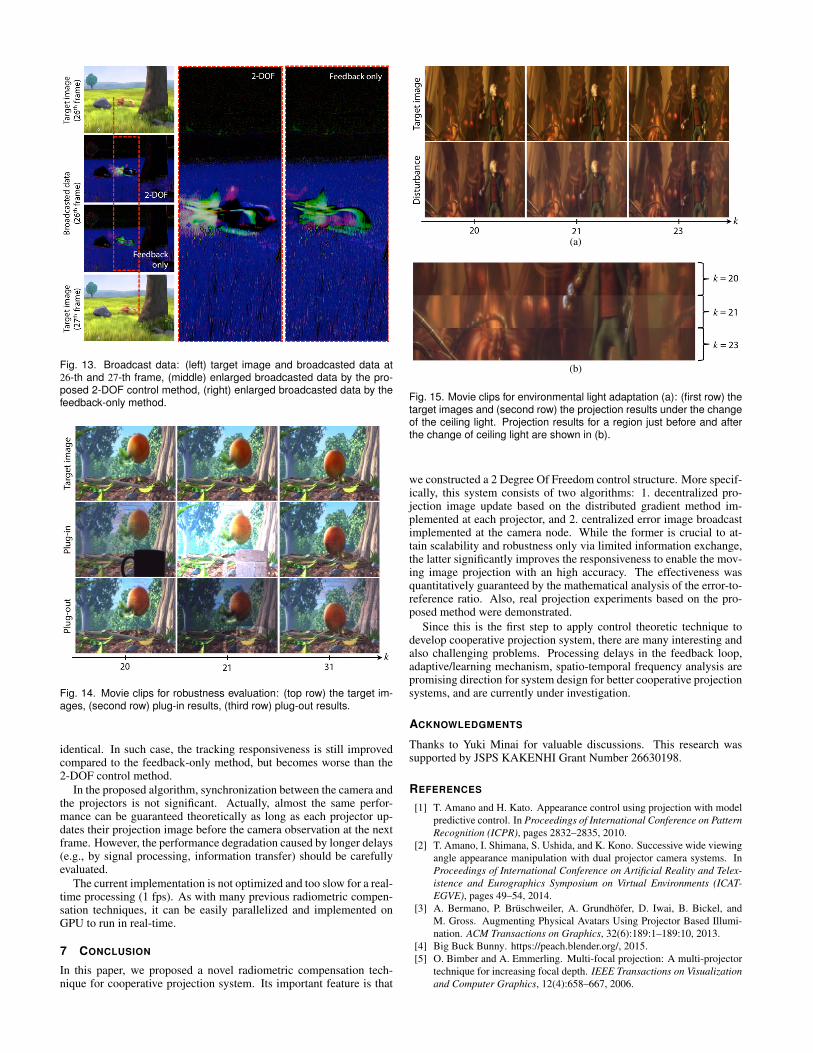
Fig. 13. Broadcast data: (left) target image and broadcasted data at26-th and 27-th frame, (middle) enlarged broadcasted data by the pro-posed 2-DOF control method, (right) enlarged broadcasted data by thefeedback-only method.
Fig. 14. Movie clips for robustness evaluation: (top row) the target im-ages, (second row) plug-in results, (third row) plug-out results.
identical. In such case, the tracking responsiveness is still improvedcompared to the feedback-only method, but becomes worse than the2-DOF control method.
In the proposed algorithm, synchronization between the camera andthe projectors is not significant. Actually, almost the same perfor-mance can be guaranteed theoretically as long as each projector up-dates their projection image before the camera observation at the nextframe. However, the performance degradation caused by longer delays(e.g., by signal processing, information transfer) should be carefullyevaluated.
The current implementation is not optimized and too slow for a real-time processing (1 fps). As with many previous radiometric compen-sation techniques, it can be easily parallelized and implemented onGPU to run in real-time.
7 CONCLUSION
In this paper, we proposed a novel radiometric compensation tech-nique for cooperative projection system. Its important feature is that
(a)
(b)
Fig. 15. Movie clips for environmental light adaptation (a): (first row) thetarget images and (second row) the projection results under the changeof the ceiling light. Projection results for a region just before and afterthe change of ceiling light are shown in (b).
we constructed a 2 Degree Of Freedom control structure. More specif-ically, this system consists of two algorithms: 1. decentralized pro-jection image update based on the distributed gradient method im-plemented at each projector, and 2. centralized error image broadcastimplemented at the camera node. While the former is crucial to at-tain scalability and robustness only via limited information exchange,the latter significantly improves the responsiveness to enable the mov-ing image projection with an high accuracy. The effectiveness wasquantitatively guaranteed by the mathematical analysis of the error-to-reference ratio. Also, real projection experiments based on the pro-posed method were demonstrated.
Since this is the first step to apply control theoretic technique todevelop cooperative projection system, there are many interesting andalso challenging problems. Processing delays in the feedback loop,adaptive/learning mechanism, spatio-temporal frequency analysis arepromising direction for system design for better cooperative projectionsystems, and are currently under investigation.
ACKNOWLEDGMENTS
Thanks to Yuki Minai for valuable discussions. This research wassupported by JSPS KAKENHI Grant Number 26630198.
REFERENCES
[1] T. Amano and H. Kato. Appearance control using projection with modelpredictive control. In Proceedings of International Conference on PatternRecognition (ICPR), pages 2832–2835, 2010.
[2] T. Amano, I. Shimana, S. Ushida, and K. Kono. Successive wide viewingangle appearance manipulation with dual projector camera systems. InProceedings of International Conference on Artificial Reality and Telex-istence and Eurographics Symposium on Virtual Environments (ICAT-EGVE), pages 49–54, 2014.
[3] A. Bermano, P. Bruschweiler, A. Grundhofer, D. Iwai, B. Bickel, andM. Gross. Augmenting Physical Avatars Using Projector Based Illumi-nation. ACM Transactions on Graphics, 32(6):189:1–189:10, 2013.
[4] Big Buck Bunny. https://peach.blender.org/, 2015.[5] O. Bimber and A. Emmerling. Multi-focal projection: A multi-projector
technique for increasing focal depth. IEEE Transactions on Visualizationand Computer Graphics, 12(4):658–667, 2006.

Fig. 16. Time series of SSIM values: (left) animal, (middle) apple, and (right) hand.
[6] O. Bimber, A. Emmerling, and T. Klemmer. Embedded entertainmentwith smart projectors. IEEE Computer, 38(1):56–63, 2005.
[7] O. Bimber, D. Iwai, G. Wetzstein, and A. Grundhofer. The VisualComputing of Projector-Camera Systems. Computer Graphics Forum,27(8):2219–2254, 2008.
[8] F. Bullo, J. Cortes, and S. Martinez. Distributed Control of RoboticNetworks:A Mathematical Approach to Motion Coordination Algorithms.Princeton Series in Applied Mathmatics, 2009.
[9] Elephants Dream. https://orange.blender.org/, 2015.[10] G. F. Franklin, J. D. Powell, and M. L. Workman. Digital Control of
Dynamic System. Addison-Weley, 2nd edition, 1990.[11] L. Itti and C. Koch. Computational modeling of visual attention. Nature
Reviews Neuroscience, 2(3):194–203, 2001.[12] D. Iwai, M. Nagase, and K. Sato. Shadow removal of projected imagery
by occluder shape measurement in a multiple overlapping projection sys-tem. Virtual Reality, 18(4):245–254, 2014.
[13] M. Mesbahi and M. Egerstedt. Graph Theoretic Methods in MultiagentNetworks. Princeton Series in Applied Mathmatics, 2010.
[14] S. Mihara, D. Iwai, and K. Sato. Artifact reduction in radiometriccompensation of projector-camera systems for steep reflectance varia-tions. IEEE Transactions on Circuits and Systems for Video Technology,24(9):1631–1638, 2014.
[15] M. Nagase, D. Iwai, and K. Sato. Dynamic defocus and occlusion com-pensation of projected imagery by model-based optimal projector selec-tion in multi-projection environment. Virtual Reality, 15(2):119–132,2011.
[16] A. Nedic and A. Ozdaglar. Distributed Subgradient Method for Multi-agent Optimization. IEEE Transactions on Automatic Control, 54(1):48–61, 2009.
[17] M. Ramasubramanian, S. N. Pattanaik, and D. P. Greenberg. A perceptu-ally based physical error metric for realistic image synthesis. In Proceed-ings of SIGGRAPH, pages 73–82, 1999.
[18] K. Sato and S. Inokuchi. Range-Imaging System Utilizing Nematic Liq-uid Crystal Mask. In Proceedings of IEEE International Conference onComputer Vision (ICCV), pages 657–661, 1987.
[19] Stephen Boyd. http://www.stanford.edu/class/ee364b/lectures/subgrad method notes.pdf, 2015.
[20] J. Tsukamoto, D. Iwai, and K. Kashima. Radiometric compensation ofcooperative projection system based on distributed optimization. Trans-actions of Virtual Reality Society Japan. under review. in Japanese.
[21] D. Wang, I. Sato, T. Okabe, and Y. Sato. Radiometric compensationin a projector-camera system based on the properties of human visionsystem. In Proceedings of IEEE International Workshop on Projector-Camera Systems, 2005.
[22] Z. Wang, A. C. Bovik, H. R. Sheikh, and E. P. Simoncelli. Image qualityassessment: From error visibility to structural similarity. IEEE Transac-tions on Image Processing, 13(4):600–612, 2004.
[23] T. Yoshida, C. Horii, and K. Sato. A virtual color reconstruction systemfor real heritage with light projection. In Proceedings of InternationalConference on Virtual Systems and Multimedia, pages 161–168, 2003.
[24] S. Zollmann and O. Bimber. Imperceptible calibration for radiometriccompensation. In Proceedings of Eurographics, pages 61–64, 2007.