radiodetection’s advanced water leak correlator · radiodetection’s advanced water leak...
TRANSCRIPT
RD533Radiodetection’s advanced water leak correlator
Operation Manual l Issue 2 l June 2009
90/RD533-OPMAN-ENG/02
ii RD533 Operation Manual RD533 Operation Manual iii
Preface
Before you begin
Thank you for your interest in Radiodetection’s RD533 water leak correlator.
Please read this user manual before attempting to use the RD533 system.
Radiodetection products, including this manual, are under continuous development. The information contained within is accurate at time of publication; however the RD533, this manual and all its contents are subject to change.
Radiodetection Limited reserves the right to modify the product without notice and some product changes may have taken place after this user manual was published.
Contact your local Radiodetection dealer or visit www.radiodetection.com for the latest information about the RD533 product family, including this manual.
Important notices
General
This instrument, or family of instruments, will not be permanently damaged by reasonable electrostatic discharge and has been tested in accordance with IEC 801-2. However, in extreme cases temporary malfunction may occur. If this happens, switch off, wait and switch on again. If the instrument still malfunctions, disconnect the batteries for a few seconds.
Safety
This equipment should be used by fully qualified and trained personnel only.
Reduce audio level before using headphones to avoid damaging your hearing.
WARNING! This equipment is NOT approved for use in areas where hazardous gases may be present.
iv RD533 Operation Manual RD533 Operation Manual v
Training
Radiodetection provides training services for most Radiodetection products. Our qualified instructors will train equipment operators or other personnel at your preferred location or at Radiodetection headquarters.
For more information go to www.radiodetection.com or contact your local Radiodetection representative.
Trademarks
RD533 is a trademark of Radiodetection Ltd.
Copyright statement
Copyright 2009 Radiodetection Ltd – SPX Corporation. All rights reserved.
Radiodetection is a subsidiary of SPX Corporation.
SPX and Radiodetection are trademarks of Radiodetection Ltd. and SPX Corporation. Due to a policy of continued development, we reserve the right to alter or amend any published specification without notice.
This document is protected by copyright and may not be copied, reproduced, transmitted, modified or used, in whole or in part, without the prior written consent of Radiodetection Ltd.
Table of contents
Preface iiiBefore you begin iiiImportant notices iiiGeneral iiiSafety iiiTraining ivTrademarks ivCopyright statement iv
Section 1 – Introduction 11.1 Overview 1
Section 2 – Measurement procedures 22.1 Setting pipe parameters 22.2 Input of Measurement Parameters 32.3 Measurement Procedure 42.3.1 General issues 42.3.2 Measuring with Automatic Mode 42.3.3 Measuring in Manual Mode 4
Section 3 – Managing data 53.1 Save, load or delete data 53.1.1 General issues 53.2.1 Print Data 5
Section 4 – Setting the number of radio sections 6
Section 5 – General settings 75.1 Language 75.2 Battery charge 85.3 Time 85.4 Date 95.5 Service 95.6 Number of means (N) 9
vi RD533 Operation Manual RD533 Operation Manual �
Section 6 – Using a geophone 106.1 Settings 116.1.1 Frequency / Mode of Operation 116.1.2 Volume 126.1.3 Indication of Noise Level 126.1.4 Automatic modulation 126.2 Measurement procedure 126.2.1 General issues 126.2.2 Pre-locating the leakage spot 126.2.3 Precise calibration 13
Section 7 – Charging the central unit 147.1 General issues 147.2 Memory Effect 147.3 Power Supply 14
Section 8 – Appendix 158.1 Technical specifications 158.2 Radio Licence Requirements 17
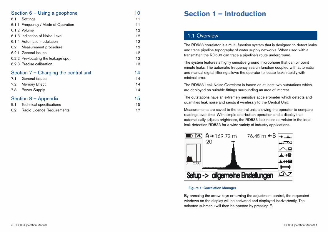
Section 1 – Introduction
1.1 Overview
The RD533 correlator is a multi-function system that is designed to detect leaks and trace pipeline topography of water supply networks. When used with a transmitter, the RD533 can trace a pipeline’s route underground.
The system features a highly sensitive ground microphone that can pinpoint minute leaks. The automatic frequency search function coupled with automatic and manual digital filtering allows the operator to locate leaks rapidly with minimal error.
The RD533 Leak Noise Correlator is based on at least two outstations which are deployed on suitable fittings surrounding an area of interest.
The outstations have an extremely sensitive accelerometer which detects and quantifies leak noise and sends it wirelessly to the Central Unit.
Measurements are saved to the central unit, allowing the operator to compare readings over time. With simple one-button operation and a display that automatically adjusts brightness, the RD533 leak noise correlator is the ideal leak detection RD533 for a wide variety of industry applications.
Figure 1: Correlation Manager
By pressing the arrow keys or turning the adjustment control, the requested windows on the display will be activated and displayed inadvertently. The selected submenu will then be opened by pressing E.
F.A.S.T.GmbH * Bössingerstr. 36 * D-74243 Langenbrettach Tel.: 07946/921000 * Fax: 07946/7153 * E-mail: [email protected] * Internet: www.FASTGMBH.de
-4-
H:\Marketing Communications\6. Product Portfolios & Launch Documents\6. Water Leak Detection\FAST Manuals\Word Copies Original\LOKAL300Version2englisch.doc
Operating Instructions for the LOKAL 300 Correlator
General issues:
When the LOKAL 300 correlator was designed and developed, it was made sure that the device can be operated even without reading any operating instructions due to the application of unambiguous and easy-to-understand symbols. These symbols are additionally explained in these Operating Instructions so that unskilled workers can operate the correlator after brief studies of these Instructions.
Illustration 1: Correlation Manager
By pressing the arrow keys or by turning the adjusting knob, the requested windows on the display will be activated and displayed invertedly. The selected submenu will then be opened by pressing ”E“ = Enter.
1. Measurement Procedures
1.1 Input of Pipe Parameters
Illustration 2: Input of Pipe Parameters
2 RD533 Operation Manual RD533 Operation Manual 3
Section 2 – Measurement procedures
2.1 Setting pipe parameters
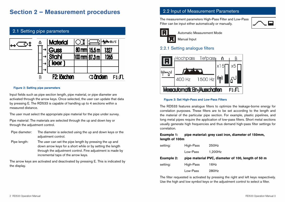
Figure 2: Setting pipe parameters
Input fields such as pipe section length, pipe material, or pipe diameter are activated through the arrow keys. Once selected, the user can update that data by pressing E. The RD533 is capable of handling up to 4 sections within a measured distance.
The user must select the appropriate pipe material for the pipe under survey.
Pipe material: The materials are selected through the up and down key or through the adjustment control.
Pipe diameter: The diameter is selected using the up and down keys or the adjustment control.
Pipe length: The user can set the pipe length by pressing the up and down arrow keys for a short while or by setting the length through the adjustment control. Fine adjustment is made by incremental taps of the arrow keys.
The arrow keys are activated and deactivated by pressing E. This is indicated by the display.
2.2 Input of Measurement Parameters
The measurement parameters High-Pass Filter and Low-Pass Filter can be input either automatically or manually.
Automatic Measurement Mode
Manual Input
2.2.1 Setting analogue filters
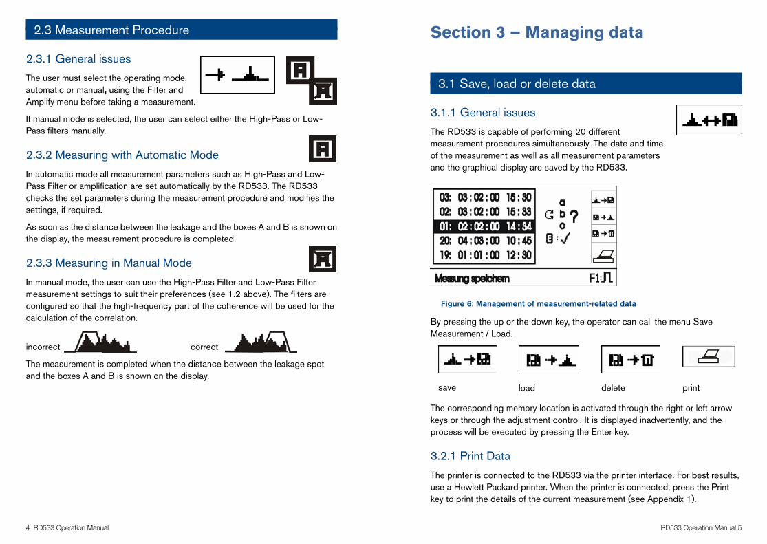
Figure 3: Set High-Pass and Low-Pass Filters
The RD533 features analogue filters to optimize the leakage-borne energy for correlation purposes. These filters are to be set according to the length and the material of the particular pipe section. For example, plastic pipelines, and long metal pipes require the application of low-pass filters. Short metal sections usually generate high frequencies and thus demand high-pass filter settings for correlation.
Example 1: pipe material: grey cast iron, diameter of 150mm, length of 100m
setting: High-Pass 250Hz
Low-Pass 1,200Hz
Example 2: pipe material PVC, diameter of 100, length of 50 m
setting: High-Pass 16Hz
Low-Pass 280Hz
The filter requested is activated by pressing the right and left keys respectively. Use the high and low symbol keys or the adjustment control to select a filter.
F.A.S.T.GmbH * Bössingerstr. 36 * D-74243 Langenbrettach Tel.: 07946/921000 * Fax: 07946/7153 * E-mail: [email protected] * Internet: www.FASTGMBH.de
-4-
H:\Marketing Communications\6. Product Portfolios & Launch Documents\6. Water Leak Detection\FAST Manuals\Word Copies Original\LOKAL300Version2englisch.doc
Operating Instructions for the LOKAL 300 Correlator
General issues:
When the LOKAL 300 correlator was designed and developed, it was made sure that the device can be operated even without reading any operating instructions due to the application of unambiguous and easy-to-understand symbols. These symbols are additionally explained in these Operating Instructions so that unskilled workers can operate the correlator after brief studies of these Instructions.
Illustration 1: Correlation Manager
By pressing the arrow keys or by turning the adjusting knob, the requested windows on the display will be activated and displayed invertedly. The selected submenu will then be opened by pressing ”E“ = Enter.
1. Measurement Procedures
1.1 Input of Pipe Parameters
Illustration 2: Input of Pipe Parameters
F.A.S.T.GmbH * Bössingerstr. 36 * D-74243 Langenbrettach Tel.: 07946/921000 * Fax: 07946/7153 * E-mail: [email protected] * Internet: www.FASTGMBH.de
-5-
H:\Marketing Communications\6. Product Portfolios & Launch Documents\6. Water Leak Detection\FAST Manuals\Word Copies Original\LOKAL300Version2englisch.doc
The requested input fields such as pipe section length, pipe material, or pipe diameter are activated through the arrow keys, and data can be input after the operator has pressed “E”. The device is capable of handling up to 4 sections within a measured distance. The particular pipe material has to be keyed in in the order of its application in the pipe system beginning with the pipe section material at the red measuring box A.
Pipe material: The materials are selected through the keys / or through the adjusting knob.
Pipe diameter: The diameter is selected through / or through the adjusting knob.
Pipe length: Pressing the arrow keys / for a short while or by setting the length through the adjusting knob, the operator will coarsely set the pipe length. Fine adjustment is made through brief tapping of the particular arrow keys.
The arrow keys are activated / deactivated by pressing “E“, and the particular mode is shown on the display: activated deactivated
1.2 Input of Measurement Parameters
The measurement parameters `High-Pass Filter´ and `Low-Pass Filter´ can be input either automatically or manually.
Automatic Measurement Mode
Manual Input
Setting of Analogue Filters (only for manual mode)
Illustration 3: Set High-Pass and Low-Pass Filters
The LOKAL 300 correlator features analogue filters to optimize the leakage-borne energy for correlation purposes. These filters are to be set according to the length and the material of the particular pipe section. Plastic pipelines, for example, and long metal pipes require the application of low-pass filters. Short metal sections usually generate high frequencies and thus demand high-pass filter settings for correlation.
F.A.S.T.GmbH * Bössingerstr. 36 * D-74243 Langenbrettach Tel.: 07946/921000 * Fax: 07946/7153 * E-mail: [email protected] * Internet: www.FASTGMBH.de
-5-
H:\Marketing Communications\6. Product Portfolios & Launch Documents\6. Water Leak Detection\FAST Manuals\Word Copies Original\LOKAL300Version2englisch.doc
The requested input fields such as pipe section length, pipe material, or pipe diameter are activated through the arrow keys, and data can be input after the operator has pressed “E”. The device is capable of handling up to 4 sections within a measured distance. The particular pipe material has to be keyed in in the order of its application in the pipe system beginning with the pipe section material at the red measuring box A.
Pipe material: The materials are selected through the keys / or through the adjusting knob.
Pipe diameter: The diameter is selected through / or through the adjusting knob.
Pipe length: Pressing the arrow keys / for a short while or by setting the length through the adjusting knob, the operator will coarsely set the pipe length. Fine adjustment is made through brief tapping of the particular arrow keys.
The arrow keys are activated / deactivated by pressing “E“, and the particular mode is shown on the display: activated deactivated
1.2 Input of Measurement Parameters
The measurement parameters `High-Pass Filter´ and `Low-Pass Filter´ can be input either automatically or manually.
Automatic Measurement Mode
Manual Input
Setting of Analogue Filters (only for manual mode)
Illustration 3: Set High-Pass and Low-Pass Filters
The LOKAL 300 correlator features analogue filters to optimize the leakage-borne energy for correlation purposes. These filters are to be set according to the length and the material of the particular pipe section. Plastic pipelines, for example, and long metal pipes require the application of low-pass filters. Short metal sections usually generate high frequencies and thus demand high-pass filter settings for correlation.
� RD533 Operation Manual RD533 Operation Manual 5
2.3 Measurement Procedure
2.3.1 General issues
The user must select the operating mode, automatic or manual, using the Filter and Amplify menu before taking a measurement.
If manual mode is selected, the user can select either the High-Pass or Low-Pass filters manually.
2.3.2 Measuring with Automatic Mode
In automatic mode all measurement parameters such as High-Pass and Low-Pass Filter or amplification are set automatically by the RD533. The RD533 checks the set parameters during the measurement procedure and modifies the settings, if required.
As soon as the distance between the leakage and the boxes A and B is shown on the display, the measurement procedure is completed.
2.3.3 Measuring in Manual Mode
In manual mode, the user can use the High-Pass Filter and Low-Pass Filter measurement settings to suit their preferences (see 1.2 above). The filters are configured so that the high-frequency part of the coherence will be used for the calculation of the correlation.
incorrect correct
The measurement is completed when the distance between the leakage spot and the boxes A and B is shown on the display.
Section 3 – Managing data
3.1 Save, load or delete data
3.1.1 General issues
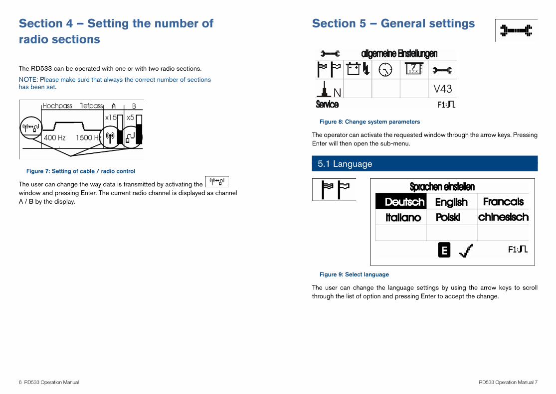
The RD533 is capable of performing 20 different measurement procedures simultaneously. The date and time of the measurement as well as all measurement parameters and the graphical display are saved by the RD533.
Figure 6: Management of measurement-related data
By pressing the up or the down key, the operator can call the menu Save Measurement / Load.
save load delete print The corresponding memory location is activated through the right or left arrow keys or through the adjustment control. It is displayed inadvertently, and the process will be executed by pressing the Enter key.
3.2.1 Print Data
The printer is connected to the RD533 via the printer interface. For best results, use a Hewlett Packard printer. When the printer is connected, press the Print key to print the details of the current measurement (see Appendix 1).
F.A.S.T.GmbH * Bössingerstr. 36 * D-74243 Langenbrettach Tel.: 07946/921000 * Fax: 07946/7153 * E-mail: [email protected] * Internet: www.FASTGMBH.de
-6-
H:\Marketing Communications\6. Product Portfolios & Launch Documents\6. Water Leak Detection\FAST Manuals\Word Copies Original\LOKAL300Version2englisch.doc
Example 1: pipe material: grey cast iron, diameter of 150, length of 100m
setting: High-Pass 250 Hz Low-Pass 1,200 Hz
Example 2: pipe material PVC, diameter of 100, length of 50 m
setting: High-Pass 16 Hz Low-Pass 280 Hz
The filter requested is activated by pressing the keys ”right“ and “left” respectively. The symbol keys “high” and “low” as well as the adjusting knob are used for the setting of the particular filter.
1.3 Measurement Procedure
General issues:
The desired operating mode (AUTOMATIC or MANUAL) has to be selected in the “Filter and Amplify“ menu prior to the measurement. If the manual mode is selected, the operator has manually to set the appropriate High-Pass and Low-Pass filters respectively.
1.3.1. Measurement in the Automatic Mode
All measurement parameters such as High-Pass and Low-Pass Filter or amplification are set automatically by the correlator. The device checks the set parameters during the measurement procedure and modifies the settings, if required.As soon as the distance between the leakage and the boxes A and B is shown on the display, the measurement procedure is completed.
1.3.2 Measurement in the Manual Mode
The High-Pass Filter and Low-Pass Filter measurement parameters can also be set according to the operator’s particular preferences (see 1.2 above). The filters are set such way that the high-frequency part of the coherence will be used for the calculation of the correlation.
incorrect correct
As soon as the distance between the leakage spot and the boxes A and B is shown on the display, the measurement procedure is completed.
F.A.S.T.GmbH * Bössingerstr. 36 * D-74243 Langenbrettach Tel.: 07946/921000 * Fax: 07946/7153 * E-mail: [email protected] * Internet: www.FASTGMBH.de
-7-
H:\Marketing Communications\6. Product Portfolios & Launch Documents\6. Water Leak Detection\FAST Manuals\Word Copies Original\LOKAL300Version2englisch.doc
2. Management of Measurement Data
2.1. Save, Load, or Delete Data
General issues:
The device is capable of administrating 20 different measurement procedures simultaneously. The date and time of the measurement as well as all measurement parameters and the graphical display are saved by the correlator.
Illustration 6: Management of measurement-related data
By pressing the „up“ or the „down“ key, the operator can call the menu ”Save Measurement / Load ”.
save load delete print
The corresponding memory location is activated through the “right” or “left” arrow keys or through the adjusting knob. It is displayed “invertedly”, and the process will be executed by pressing the “Enter” key.
2.2. Print Data
The printer is interconnected with the device through the printer interface (preferably HP products). When the printer is ready for operation, the data of the current measurement will be printed out by pressing the “Print“ key (see Appendix 1).
3. Setting the Number of Radio Sections
The LOKAL 300 correlator can be operated with one or with two radio sections. Please make sure that always the correct number of sections has been set !!
F.A.S.T.GmbH * Bössingerstr. 36 * D-74243 Langenbrettach Tel.: 07946/921000 * Fax: 07946/7153 * E-mail: [email protected] * Internet: www.FASTGMBH.de
-6-
H:\Marketing Communications\6. Product Portfolios & Launch Documents\6. Water Leak Detection\FAST Manuals\Word Copies Original\LOKAL300Version2englisch.doc
Example 1: pipe material: grey cast iron, diameter of 150, length of 100m
setting: High-Pass 250 Hz Low-Pass 1,200 Hz
Example 2: pipe material PVC, diameter of 100, length of 50 m
setting: High-Pass 16 Hz Low-Pass 280 Hz
The filter requested is activated by pressing the keys ”right“ and “left” respectively. The symbol keys “high” and “low” as well as the adjusting knob are used for the setting of the particular filter.
1.3 Measurement Procedure
General issues:
The desired operating mode (AUTOMATIC or MANUAL) has to be selected in the “Filter and Amplify“ menu prior to the measurement. If the manual mode is selected, the operator has manually to set the appropriate High-Pass and Low-Pass filters respectively.
1.3.1. Measurement in the Automatic Mode
All measurement parameters such as High-Pass and Low-Pass Filter or amplification are set automatically by the correlator. The device checks the set parameters during the measurement procedure and modifies the settings, if required.As soon as the distance between the leakage and the boxes A and B is shown on the display, the measurement procedure is completed.
1.3.2 Measurement in the Manual Mode
The High-Pass Filter and Low-Pass Filter measurement parameters can also be set according to the operator’s particular preferences (see 1.2 above). The filters are set such way that the high-frequency part of the coherence will be used for the calculation of the correlation.
incorrect correct
As soon as the distance between the leakage spot and the boxes A and B is shown on the display, the measurement procedure is completed.
F.A.S.T.GmbH * Bössingerstr. 36 * D-74243 Langenbrettach Tel.: 07946/921000 * Fax: 07946/7153 * E-mail: [email protected] * Internet: www.FASTGMBH.de
-6-
H:\Marketing Communications\6. Product Portfolios & Launch Documents\6. Water Leak Detection\FAST Manuals\Word Copies Original\LOKAL300Version2englisch.doc
Example 1: pipe material: grey cast iron, diameter of 150, length of 100m
setting: High-Pass 250 Hz Low-Pass 1,200 Hz
Example 2: pipe material PVC, diameter of 100, length of 50 m
setting: High-Pass 16 Hz Low-Pass 280 Hz
The filter requested is activated by pressing the keys ”right“ and “left” respectively. The symbol keys “high” and “low” as well as the adjusting knob are used for the setting of the particular filter.
1.3 Measurement Procedure
General issues:
The desired operating mode (AUTOMATIC or MANUAL) has to be selected in the “Filter and Amplify“ menu prior to the measurement. If the manual mode is selected, the operator has manually to set the appropriate High-Pass and Low-Pass filters respectively.
1.3.1. Measurement in the Automatic Mode
All measurement parameters such as High-Pass and Low-Pass Filter or amplification are set automatically by the correlator. The device checks the set parameters during the measurement procedure and modifies the settings, if required.As soon as the distance between the leakage and the boxes A and B is shown on the display, the measurement procedure is completed.
1.3.2 Measurement in the Manual Mode
The High-Pass Filter and Low-Pass Filter measurement parameters can also be set according to the operator’s particular preferences (see 1.2 above). The filters are set such way that the high-frequency part of the coherence will be used for the calculation of the correlation.
incorrect correct
As soon as the distance between the leakage spot and the boxes A and B is shown on the display, the measurement procedure is completed.
� RD533 Operation Manual RD533 Operation Manual �
Section 4 – Setting the number of radio sections
The RD533 can be operated with one or with two radio sections.
NOTE: Please make sure that always the correct number of sections has been set.
Figure 7: Setting of cable / radio control
The user can change the way data is transmitted by activating the window and pressing Enter. The current radio channel is displayed as channel A / B by the display.
Section 5 – General settings
Figure 8: Change system parameters
The operator can activate the requested window through the arrow keys. Pressing Enter will then open the sub-menu.
5.1 Language
Figure 9: Select language
The user can change the language settings by using the arrow keys to scroll through the list of option and pressing Enter to accept the change.
F.A.S.T.GmbH * Bössingerstr. 36 * D-74243 Langenbrettach Tel.: 07946/921000 * Fax: 07946/7153 * E-mail: [email protected] * Internet: www.FASTGMBH.de
-7-
H:\Marketing Communications\6. Product Portfolios & Launch Documents\6. Water Leak Detection\FAST Manuals\Word Copies Original\LOKAL300Version2englisch.doc
2. Management of Measurement Data
2.1. Save, Load, or Delete Data
General issues:
The device is capable of administrating 20 different measurement procedures simultaneously. The date and time of the measurement as well as all measurement parameters and the graphical display are saved by the correlator.
Illustration 6: Management of measurement-related data
By pressing the „up“ or the „down“ key, the operator can call the menu ”Save Measurement / Load ”.
save load delete print
The corresponding memory location is activated through the “right” or “left” arrow keys or through the adjusting knob. It is displayed “invertedly”, and the process will be executed by pressing the “Enter” key.
2.2. Print Data
The printer is interconnected with the device through the printer interface (preferably HP products). When the printer is ready for operation, the data of the current measurement will be printed out by pressing the “Print“ key (see Appendix 1).
3. Setting the Number of Radio Sections
The LOKAL 300 correlator can be operated with one or with two radio sections. Please make sure that always the correct number of sections has been set !!
F.A.S.T.GmbH * Bössingerstr. 36 * D-74243 Langenbrettach Tel.: 07946/921000 * Fax: 07946/7153 * E-mail: [email protected] * Internet: www.FASTGMBH.de
-9-
H:\Marketing Communications\6. Product Portfolios & Launch Documents\6. Water Leak Detection\FAST Manuals\Word Copies Original\LOKAL300Version2englisch.doc
The operator can change the way of data transmission by activating the window and pressing „Enter“. The selected kind of transmission will be displayed in the channel A / B sector.
4. General Settings
Illustration 8: Change system parameters
The operator can activate the requested window through the arrow keys. Pressing “Enter” then opens the sub-menu.
4.1 Language
Illustration 9: Select language
The requested language is activated through the arrow keys and will be set by pressing „Enter“.
� RD533 Operation Manual RD533 Operation Manual 9
5.2 Battery charge
Figure 10: Displaying the battery voltage
Permissible values:
battery fully charged: approx. 8.4 volt
low battery: approx. 7.1 volt
5.3 Time
Figure 11: Setting the time
The user can set the time using the arrow keys. Once the correct time is displayed, press the Enter key to accept the change.
5.4 Date
Figure 12: Setting the date
The user can set the date using the arrow keys. Once the correct date is displayed, press the Enter key to accept the change.
5.5 Service
The service menu is for service and maintenance technicians only.
5.6 Number of means (N)
Usually, the means of 20 measurements are sufficient to generate an accurate correlation image. In case of plastic pipes, however, we recommend more measurements for greater accuracy.
When the window is activated, the actual number of means will flash on the display. This number can be modified in increments of 10 by pressing the up and down arrow keys. Press Enter to accept the new number of means.
F.A.S.T.GmbH * Bössingerstr. 36 * D-74243 Langenbrettach Tel.: 07946/921000 * Fax: 07946/7153 * E-mail: [email protected] * Internet: www.FASTGMBH.de
-10-
H:\Marketing Communications\6. Product Portfolios & Launch Documents\6. Water Leak Detection\FAST Manuals\Word Copies Original\LOKAL300Version2englisch.doc
4.2 Accumulator Voltage
Illustration 10: Displaying the accumulator voltage
Permissible values:
- accumulator fully charged: approx. 8.4 volt - accumulator down: approx. 7.1 volt
4.3 Time
Illustration 11: Set the time
The time is set through the arrow keys and will be accepted by pressing „Enter“.
F.A.S.T.GmbH * Bössingerstr. 36 * D-74243 Langenbrettach Tel.: 07946/921000 * Fax: 07946/7153 * E-mail: [email protected] * Internet: www.FASTGMBH.de
-11-
H:\Marketing Communications\6. Product Portfolios & Launch Documents\6. Water Leak Detection\FAST Manuals\Word Copies Original\LOKAL300Version2englisch.doc
4.4 Date
Illustration 12: Set the date
The date is set through the arrow keys and will be accepted by pressing “Enter”.
4.5 Service
This window is used for the setting of special system parameters. Please do not key in any data !
4.6 Number of Means “N“
Usually, the means of 20 measurements are sufficient to generate a convincing correlation image. In case of plastic pipes, however, we recommend more measurements for enhanced correctness. When the window is activated, the actual number of means starts flashing.. This number can be modified in steps of 10 by pressing the arrow keys (up / down). The desired number will then be accepted by pressing “Enter”.
�0 RD533 Operation Manual RD533 Operation Manual ��
Section 6 – Using a geophone
To use the geophone, the user can access Geophone Operation menu in the Correlation Manager.
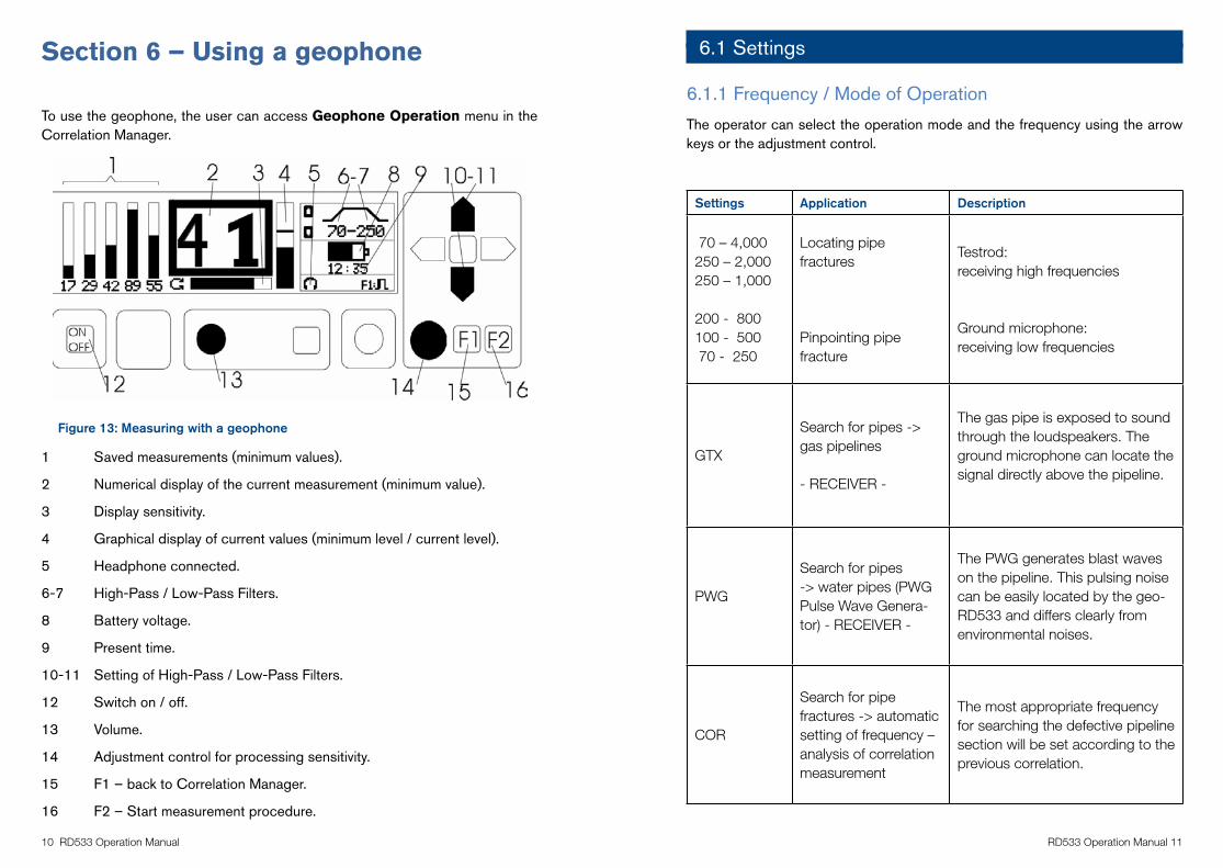
Figure 13: Measuring with a geophone
1 Saved measurements (minimum values).
2 Numerical display of the current measurement (minimum value).
3 Display sensitivity.
4 Graphical display of current values (minimum level / current level).
5 Headphone connected.
6-7 High-Pass / Low-Pass Filters.
8 Battery voltage.
9 Present time.
10-11 Setting of High-Pass / Low-Pass Filters.
12 Switch on / off.
13 Volume.
14 Adjustment control for processing sensitivity.
15 F1 – back to Correlation Manager.
16 F2 – Start measurement procedure.
6.1 Settings
6.1.1 Frequency / Mode of Operation
The operator can select the operation mode and the frequency using the arrow keys or the adjustment control.
Settings Application Description
70 – 4,000 250 – 2,000250 – 1,000
200 - �00�00 - 500 �0 - 250
Locating pipe fractures
Pinpointing pipe fracture
Testrod:receiving high frequencies
Ground microphone:receiving low frequencies
GTX
Search for pipes -> gas pipelines
- RECEIVER -
The gas pipe is exposed to sound through the loudspeakers. The ground microphone can locate the signal directly above the pipeline.
PWG
Search for pipes -> water pipes (PWG Pulse Wave Genera-tor) - RECEIVER -
The PWG generates blast waves on the pipeline. This pulsing noise can be easily located by the geo-RD533 and differs clearly from environmental noises.
COR
Search for pipe fractures -> automatic setting of frequency – analysis of correlation measurement
The most appropriate frequency for searching the defective pipeline section will be set according to the previous correlation.
F.A.S.T.GmbH * Bössingerstr. 36 * D-74243 Langenbrettach Tel.: 07946/921000 * Fax: 07946/7153 * E-mail: [email protected] * Internet: www.FASTGMBH.de
-12-
H:\Marketing Communications\6. Product Portfolios & Launch Documents\6. Water Leak Detection\FAST Manuals\Word Copies Original\LOKAL300Version2englisch.doc
5. Measurement with Geophone
The operator has to call the window “Geophone Operation“ in the Correlation Manager.
Illustration 13: - Measurement with Geophone -
1. Saved measurements (minimum values)
2. Numerical display of the current measurement (minimum value)
3. Display sensitivity
4. Graphical display of current values (minimum level / current level)
6-7. High-Pass / Low-Pass Filters
8. Battery voltage
9. Present time
10-11 Setting of High-Pass / Low-Pass Filters
12 Switch on / off
13 Volume
14 Adjusting knob for processing sensitivity
15 F1 – back to Correlation Manager
16 F2 – Start measurement procedure
�2 RD533 Operation Manual RD533 Operation Manual �3
6.1.2 Volume
The volume for the headphones is adjusted through the regulator (13).
6.1.3 Indication of Noise Level
The signal received is shown graphically (4) and numerically (2) on the LCD. The level indication is adjusted with the adjustment control (14) or through the arrow keys.
6.1.4 Automatic modulation
The level sensitivity is automatically set when Enter is pressed either during or after a measurement procedure.
6.2 Measurement procedure
6.2.1 General issues
Any pressurized pipeline system generates a leak noise at a fracture point. This noise differs according to the size and geometry of the leakage and can be picked up over the pipeline (leakage spot) or at the fittings (valves, hydrants, water meters, etc.)
6.2.2 Pre-locating the leakage spot
The area of the leakage is determined with the testrod or the RD533.
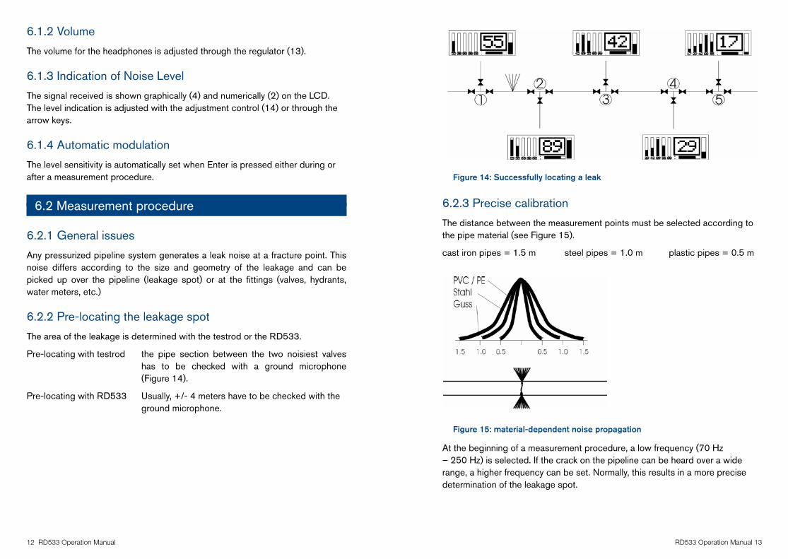
Pre-locating with testrod the pipe section between the two noisiest valves has to be checked with a ground microphone (Figure 14).
Pre-locating with RD533 Usually, +/- 4 meters have to be checked with the ground microphone.
Figure 14: Successfully locating a leak
6.2.3 Precise calibration
The distance between the measurement points must be selected according to the pipe material (see Figure 15).
cast iron pipes = 1.5 m steel pipes = 1.0 m plastic pipes = 0.5 m
Figure 15: material-dependent noise propagation
At the beginning of a measurement procedure, a low frequency (70 Hz – 250 Hz) is selected. If the crack on the pipeline can be heard over a wide range, a higher frequency can be set. Normally, this results in a more precise determination of the leakage spot.
F.A.S.T.GmbH * Bössingerstr. 36 * D-74243 Langenbrettach Tel.: 07946/921000 * Fax: 07946/7153 * E-mail: [email protected] * Internet: www.FASTGMBH.de
-14-
H:\Marketing Communications\6. Product Portfolios & Launch Documents\6. Water Leak Detection\FAST Manuals\Word Copies Original\LOKAL300Version2englisch.doc
Automatic Modulation
!!! The level sensitivity is automatically set when “Enter” is pressed either during or after a measurement procedure (symbol).
5.2 Course of Action for Measurement Procedure
General issues
Any pressurized pipeline system generates a leakage-borne noise at an untight and leaky spot. This noise differs according to the size and geometry of the leakage and can be picked up over the pipeline (leakage spot) or at the fittings (valves, hydrants, water meters, etc.)
Pre-locating the leakage spot
The area of the leakage is determined with the testrod or the correlator.
Pre-locating with testrod - the pipe section between the two noisiest valves has to be checked with a ground
microphone (illustration 14).
Pre-locating with correlator - Usually, +/- 4 meters have to be checked with the ground microphone.
Illustration 14: Succesfully spotting a leakage
F.A.S.T.GmbH * Bössingerstr. 36 * D-74243 Langenbrettach Tel.: 07946/921000 * Fax: 07946/7153 * E-mail: [email protected] * Internet: www.FASTGMBH.de
-15-
H:\Marketing Communications\6. Product Portfolios & Launch Documents\6. Water Leak Detection\FAST Manuals\Word Copies Original\LOKAL300Version2englisch.doc
Precise Calibration
The distance between the measurement points has to be chosen according to the pipe material (see illustration 15).
cast iron pipes = 1.5 m steel pipes = 1.0 m plastic pipes = 0.5 m
Illustration 15: material-dependent noise propagation
At the beginning of a measurement procedure, a low frequency (70 Hz – 250 Hz) is selected. If the crack on the pipeline can be heard over a wide range, a higher frequency can be set. Normally, this results in a more precise determination of the leakage spot.
6. Charging the Central Unit
6.1 General Issues
Fully charged accumulators have an operating time of 20 hours of permanent operation. Maximum time for charging is 4 hrs. The device automatically switches off as soon as the voltage falls below 7.1 volt (see paragraph 4.2).
Note: The correlator is inoperative while charging is under way.
6.2 Memory Effect
Memory effect is rather poor due to the application of NiMH accumulators. However, the operator should make sure that the LOKAL 300 correlator is not charged before the accumulator capacity has fallen below 25%. The current capacity is displayed graphically on the LCD.
�� RD533 Operation Manual RD533 Operation Manual �5
Section 7 – Charging the central unit
7.1 General issues
When fully charged, the batteries have an approximate operation life 20 hours. Recharging takes approximately 4 hrs. The RD533 automatically switches off as soon as the voltage falls below 7.1 volt (see Section 4.2).
NOTE: The RD533 is inoperative while charging is under way.
7.2 Memory Effect
Memory effect is rather poor due to the application of NiMH batteries. However, the user should make sure that the RD533 is not charged before the battery capacity has fallen below 25%. The current capacity is displayed graphically on the LCD.
7.3 Power Supply
The RD533 can be charged through the recharger or using12v vehicle cigarette lighter. Power supply is required to be between 12 and 14 volt, and a charging current of 2.5 ampère is needed to charge the RD533.
Section 8 – Appendix
8.1 Technical specifications
Batteriesnickel / metal / hydridecharge indication through menubatteries feature high-speed charging
Case
portable, tough aluminium case membrane keyboard with pulse rotary encoderdimensions : �� x �� x 2� cmweight : 3.2 kg
Clock integrated real-time
Connections
RS232: for communication with PCBNC: cable entry for pick-up5-pole: ground microphone / testrodjack plug: for headphones2-pole pin: power supply
RD533
state-of-the-art time domain RD533 with coherence indicatormaximum resolution: 5 cmacquired measurement points: 50,000
CPUorder processing time: 5,000,000 orders per second
Display LCD 64 x 240 pkt resolution, illuminated
Filter
automatically / manually selectable analog filters to suppress disturbing noises. The measurement routine independently sets the most appropriate filter.HP filter 1 – 1,600 Hz (16 levels)TP filter 35 – 3,500 Hz (16 levels)
�� RD533 Operation Manual RD533 Operation Manual ��
Geophone Functions
fully-applicable geophone- � frequencies for leak detection purposesreceiver for:- leak detection in gas pipelines - leak detection in metal and non-metal waterpipelines
Headphones �� - 32 ohm
Input through cable or radio, depending on model
Internal Amplification � steps : �x� to � * �5
LanguagesGerman, English, Polish, Italian, French, Chinese, Norwegian, Danish
Material Input
�2 different material parameters can be input : � different pipe materials � different pipe diameters � different pipe section lengthsSound velocity is calculated automatically by the RD533 on the basis of the input parameters.Material list: steel, cast iron, AZ, PVC, PE hard, PE soft, lead, copper, glass-fibre reinforced material
Memory 20 measurements
Power Supply
12-14 volt DC, approx. 0.25 ampère of current consumption, permanent operation time of batteries: approx. 20 hrs, maximum time required for charging: � hrs.
Radio Transmitter
transmitter power (500 mW) designed for frequencies related to leakage detection procedures.BZT licensefrequencies: 433.65 and 434.75 MHztemperature range : -�0°C up to +�0° C
Temperature Range -5°C up to +55°C
Trans-Autoautomatic integration of measurement signal to detect disturbing noises during the measurement
User Guidance simple and clear due to logical symbols
8.2 Radio Licence Requirements
The measurement boxes for the RD533 are equipped with radio transmitters. Due to their power, these radio modules have to be registered with the competent supervisory authority for telecommunication.
Technical data:
Power: 500 mW
Frequency transmitter A: 433.65 MHz
Frequency transmitter B: 434.75 MHz
The radio modules have been checked for conformity by CETECOM ICT Service GmbH:
Please apply for a licence for the equipment as soon as possible.
AmericaRadiodetection 154 Portland Road, Bridgton, ME 04009, USA Tel: +� (20�) ��� 9�95 Toll Free: +� (���) 2�� 3�9� Fax: +� (20�) ��� 9�9� Email: [email protected] Web: www.radiodetection.com
Pearpoint 72055 Corporate Way, Thousand Palms CA 92276, USA Tel: +� �00 ��� �09� Tel: +� ��0 3�3 �350 Fax: +� ��0 3�3 �35� Email: [email protected] Web: www.radiodetection.com
Radiodetection (Canada) 344 Edgeley Boulevard, Unit 34, Concord, Ontario L�K �B�, Canada Tel: +� (905) ��0 9995 Toll Free: +� (�00) ��5 �953 Fax: +� (905) ��0 95�9 Email: [email protected] Web: www.radiodetection.com
EuropeRadiodetection Ltd (UK) Western Drive, Bristol BS14 0AF, UK Tel: +�� (0) ��� 9�� ���� Fax: +�� (0) ��� 9�� ���5 Email: [email protected] Web: www.radiodetection.com
Radiodetection (France) 13 Grande Rue, 76220, Neuf Marché, France Tel: +33 (0) 2 32 �9 93 �0 Fax: +33 (0) 2 35 90 95 5� Email: [email protected] Web: http://fr.radiodetection.com
Radiodetection (Benelux) Industriestraat 11, 7041 GD ’s-Heerenberg, Netherlands Tel: +3� (0) 3�� �� �� 00 Fax: +3� (0) 3�� �� �� 30 Email: [email protected] Web: http://nl.radiodetection.com
Radiodetection (Germany) Groendahlscher Weg �18, 46446 Emmerich am Rhein, Germany Tel: +�9 (0) 2� 5� 92 3� 20 Fax: +�9 (0) 2� 5� 92 3� 520 Email: [email protected] Web: http://de.radiodetection.com
Asia-PacificRadiodetection (Asia-Pacific) Room 708, CC Wu Building, 302-308 Hennessy Road, Wan Chai, Hong Kong SAR, China Tel: +�52 2��0 ���0 Fax: +�52 2��0 9��� Email: [email protected] Web: www.radiodetection.com
Radiodetection (China) Hongfu Mansion, Room 61622, Zheng Ge Zhuang, Bei Qi Jia Town, Chang Ping District Beijing 102209, China Tel: +�� (0) �0 �9�5 55�0 Fax: +�� (0) �0 �9�5 5��0 Email: [email protected] Web: http://cn.radiodetection.com
Radiodetection (Australia) Unit 14, 5-7 Prosperity Parade, Warriewood NSW 2102, Australia Tel: +�� (0) 2 99�9 �555 Fax: +�� (0) 2 99�9 ��33 Email: [email protected] Web: www.radiodetection.com
Radiodetection products are under continuous development and are subject to change, we reserve the right to alter or amend any published specification without notice.Copyright 2009 Radiodetection Ltd. - SPX Corporation. All rights reserved. Radiodetection Ltd. is a subsidiary of SPX Corporation.
www.radiodetection.com