radiation protection at synchrotron radiation...
TRANSCRIPT
3rd ILSF Advanced School on Synchrotron Radiation and Its Applications
September 14-16, 2013
Radiation Protection At Synchrotron Radiation Facilities
Ehsan SalimiShielding and Radiation Safety Group
Iranian Light Source Facility
Outline• Introduction to Radiation shielding
• Radiation Sources at the Synchrotron Facilities
• Calculational Tools and Procedures
• Linac and Synchrotron Ring Shielding Design
• Gas Bremsstrahlung Source• Gas Bremsstrahlung Source
• Beam stop
• Labyrinth
• Personal Safety System
2
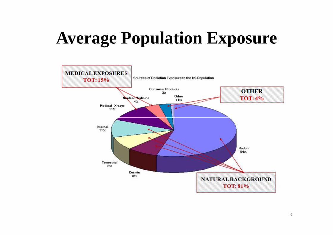
Average Population Exposure
3
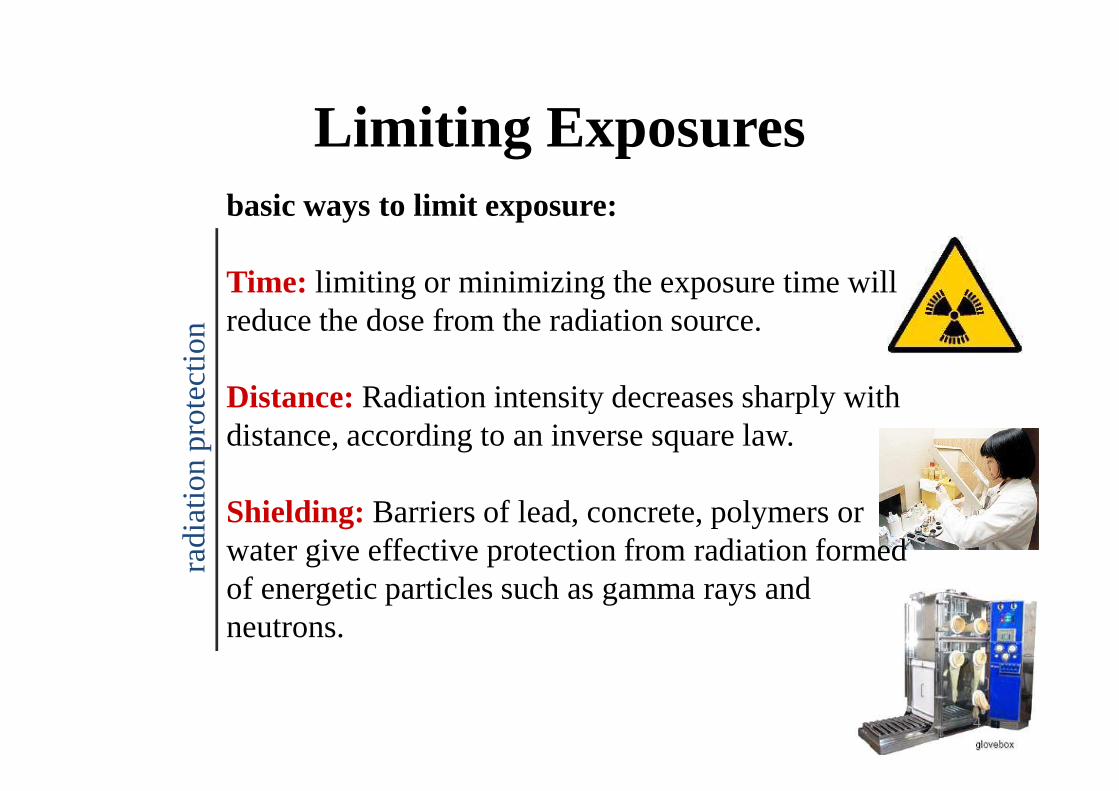
Limiting Exposuresbasic ways to limit exposure:
Time: limiting or minimizing the exposure time will reduce the dose from the radiation source.
Distance: Radiation intensity decreases sharply with
radi
atio
n pr
otec
tion
Distance: Radiation intensity decreases sharply with distance, according to an inverse square law.
Shielding: Barriers of lead, concrete, polymers or water give effective protection from radiation formed of energetic particles such as gamma rays and neutrons.
radi
atio
n pr
otec
tion
4
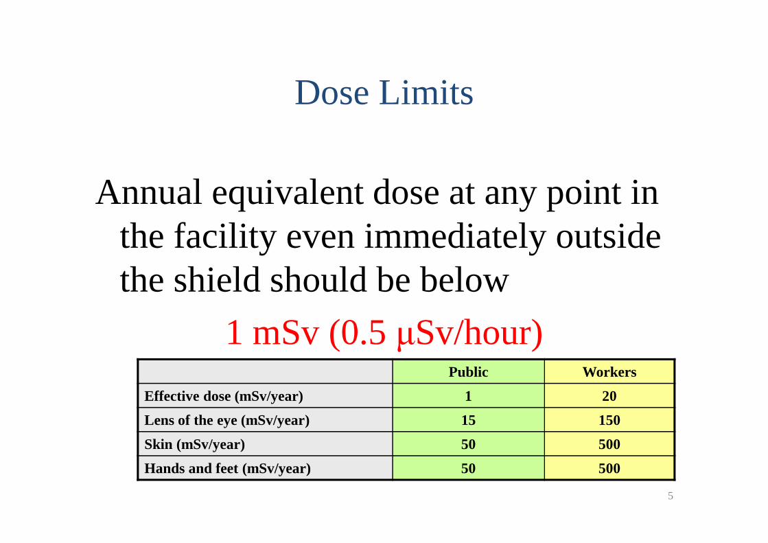
Annual equivalent dose at any point in the facility even immediately outside the shield should be below
Dose Limits
the shield should be below
1 mSv(0.5 µSv/hour)
5
Public Workers
Effective dose (mSv/year) 1 20
Lens of the eye (mSv/year) 15 150
Skin (mSv/year) 50 500
Hands and feet (mSv/year) 50 500
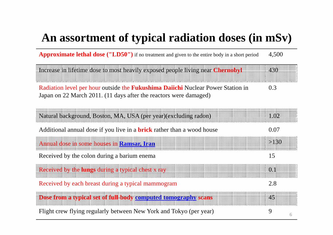
An assortment of typical radiation doses (in mSv)Approximate lethal dose ("LD50") if no treatment and given to the entire body in a short period4,500
Increase in lifetime dose to most heavily exposed people living near Chernobyl 430
Radiation level per hour outside the Fukushima Daiichi Nuclear Power Station in Japan on 22 March 2011. (11 days after the reactors were damaged)
0.3
Natural background, Boston, MA, USA (per year)(excluding radon) 1.02Natural background, Boston, MA, USA (per year)(excluding radon) 1.02
Additional annual dose if you live in a brick rather than a wood house 0.07
Annual dose in some houses in Ramsar, Iran >130
Received by the colon during a barium enema 15
Received by the lungs during a typical chest x ray 0.1
Received by each breast during a typical mammogram 2.8
Dose from a typical set of full-body computed tomography scans 45
Flight crew flying regularly between New York and Tokyo (per year) 96
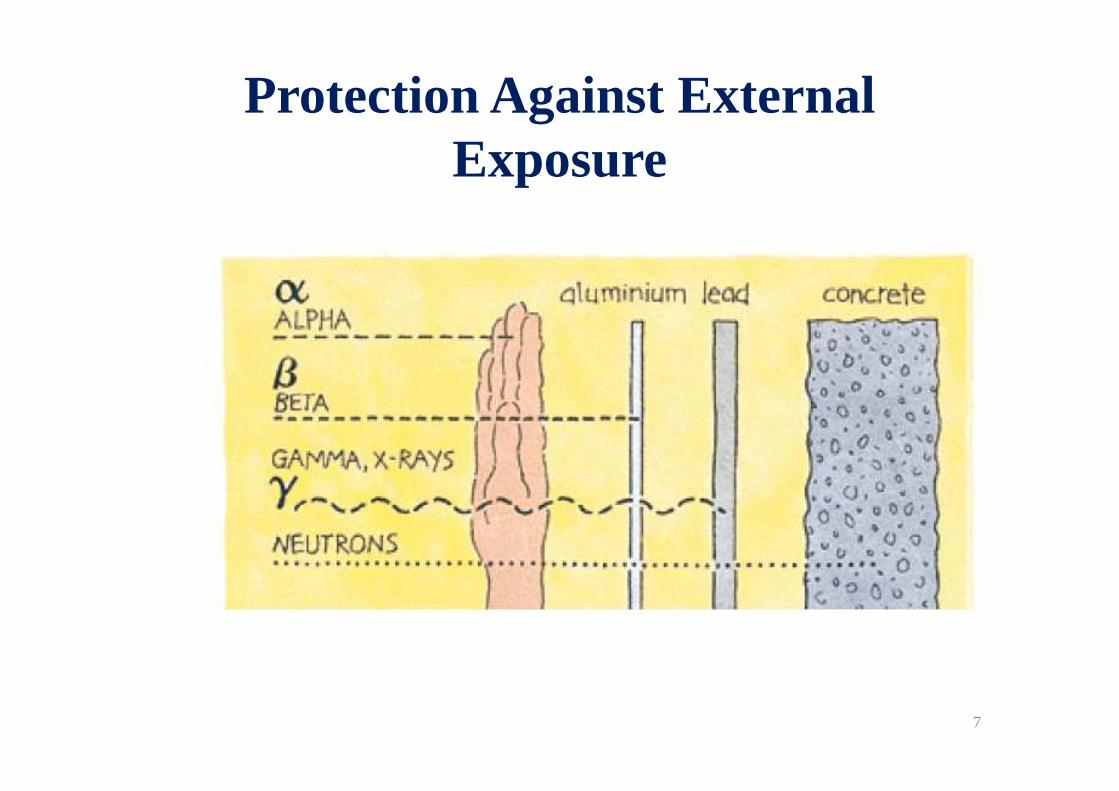
Protection Against External Exposure
7
Ionizing Radiation Hazards
• Electron beam loss during different stages of acceleration
• Electron beam loss in different parts of machine• Electron beam loss in different parts of machine
• Radiation from bending magnets and insertion devices
The radiation field from high energy electron loss depends strongly on the electron energy, target material, thickness
8
Radiation Sources
• Bremsstrahlung
� High Energy Photons
� Gas and Non-Gas
• Neutrons• Neutrons
• Synchrotron radiation
� ID and BM
� Low Energy Xrays
• Induced activation
9
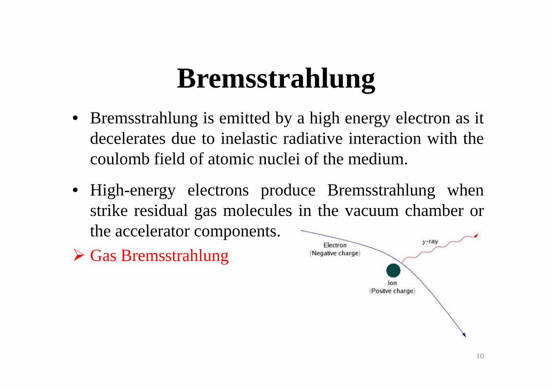
Bremsstrahlung• Bremsstrahlung is emitted by a high energy electron as it
decelerates due to inelastic radiative interaction with thecoulomb field of atomic nuclei of the medium.
• High-energy electrons produce Bremsstrahlungwhen• High-energy electrons produce Bremsstrahlungwhenstrike residual gas molecules in the vacuumchamber orthe accelerator components.
� Gas Bremsstrahlung
10
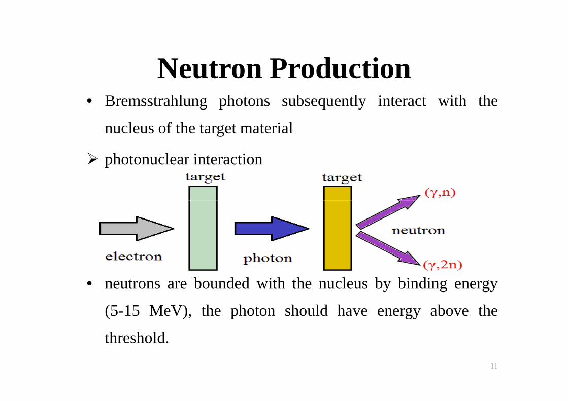
Neutron Production• Bremsstrahlung photons subsequently interact with the
nucleus of the target material
� photonuclear interaction
• neutrons are bounded with the nucleus by binding energy
(5-15 MeV), the photon should have energy above the
threshold.
11
Neutron• Giant Resonance Neutron
7 < E ph < 20 MeVAverage effective energy of about 2 MeV and emitted
isotropically
• High Energy NeutronEph >25Mev
Radiation component that dominates for thick shieldsForward peaked but not as strongly as BRM photons
12
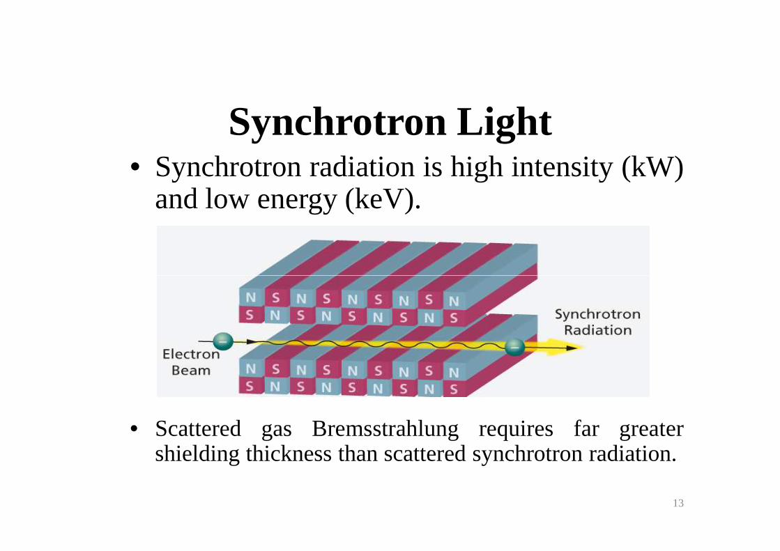
Synchrotron Light• Synchrotron radiation is high intensity (kW)
and lowenergy (keV).
• Scattered gas Bremsstrahlung requires far greatershielding thickness than scattered synchrotron radiation.
13
Induced Activation • The photoneutron interaction of Bremsstrahlung with
materials leads to the radioactivation of acceleratorcomponents through neutron emission and the productionof radioisotopes.of radioisotopes.
• The amount of activity depends on the electron energy, beam power, bremsstrahlung production efficiency, and type of material.
14
Calculational Tools
• Analytical Methods
•• Monte Carlo Methods�FLUKA and MCNPX Monte Carlo codes are
capable codes which have been used widely in shielding calculations.
15
Beam Loss
Estimation
• Linac loss points
• Transfer lines loss points
• Synchrotron accelerators loss points
16
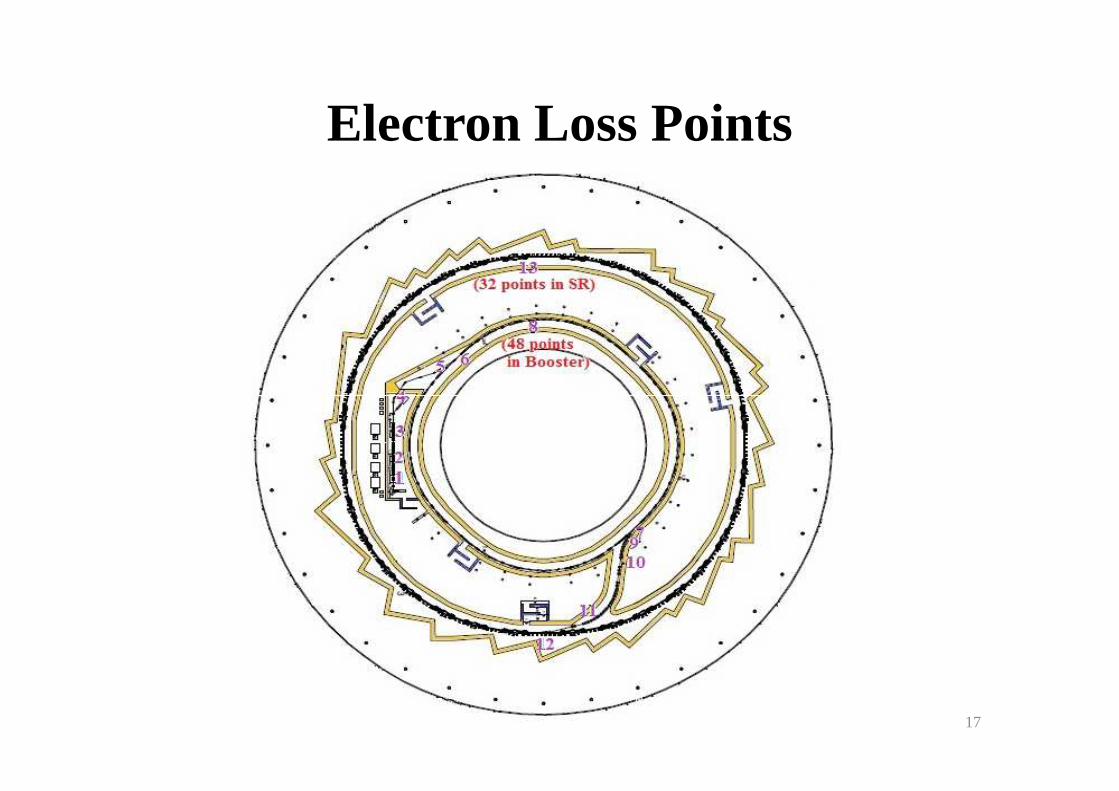
Electron Loss Points
17
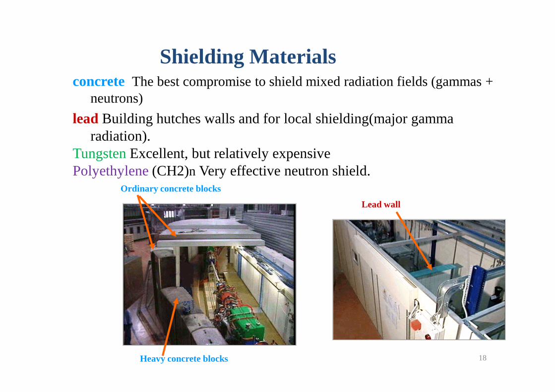
Shielding Materialsconcrete The best compromise to shield mixed radiation fields (gammas +
neutrons)
lead Building hutches walls and for local shielding(major gamma radiation).
TungstenExcellent, but relatively expensivePolyethylene (CH2)n Very effective neutron shield.
Ordinary concrete blocks
Heavy concrete blocks
Lead wall
18
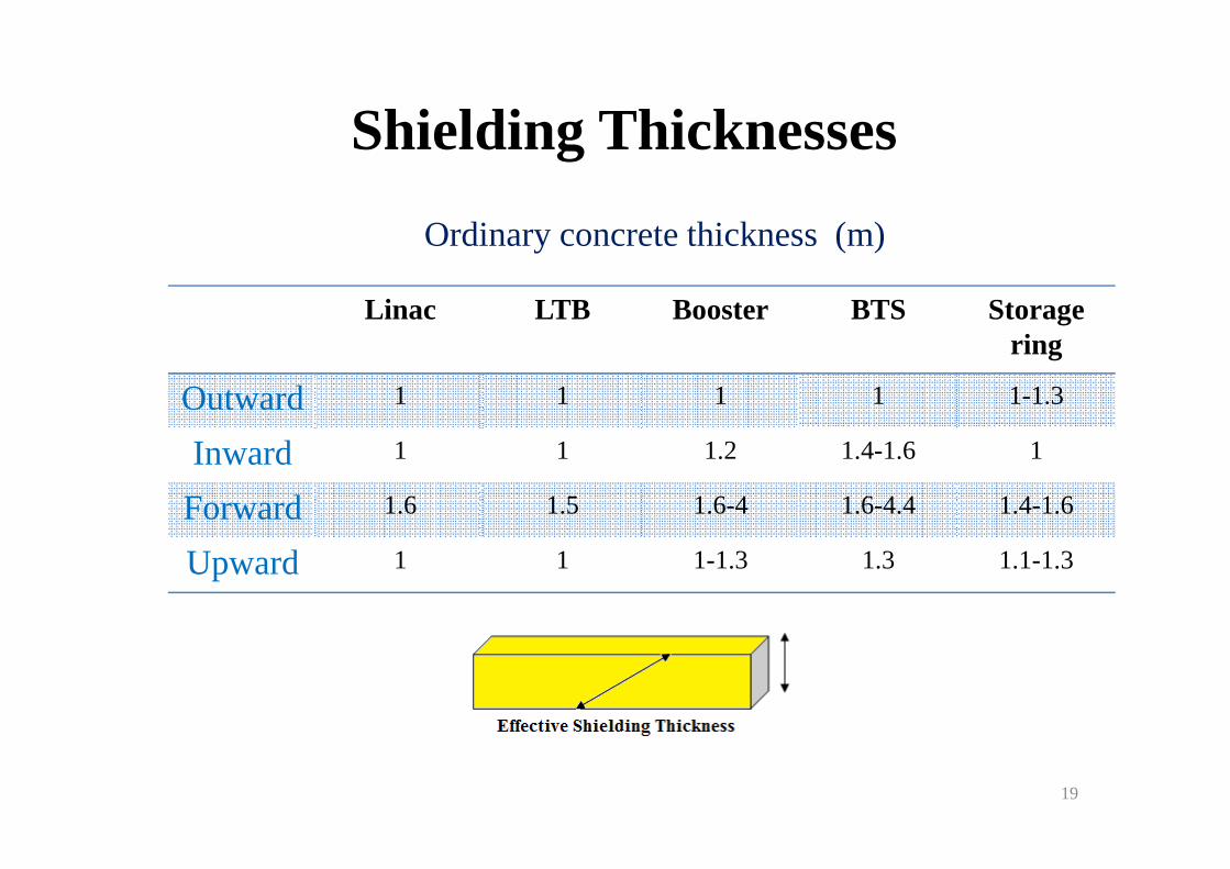
Shielding Thicknesses
Linac LTB Booster BTS Storage ring
Outward 1 1 1 1 1-1.3
Inward
Ordinary concrete thickness (m)
Inward 1 1 1.2 1.4-1.6 1
Forward 1.6 1.5 1.6-4 1.6-4.4 1.4-1.6
Upward 1 1 1-1.3 1.3 1.1-1.3
19
Monte Carlo Simulation for Characterization of
Gas Bremsstrahlung in ILSF IDs
20
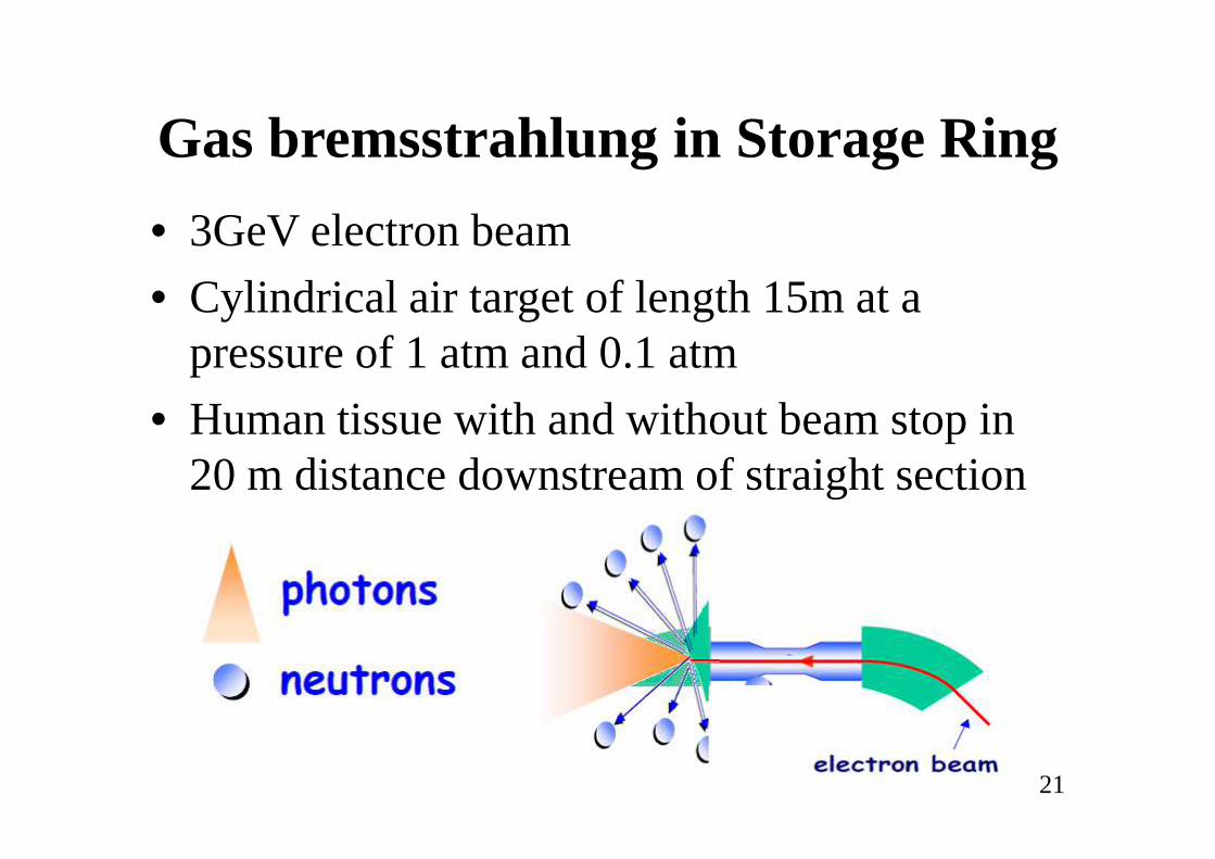
Gas bremsstrahlung in Storage Ring
• 3GeV electron beam
• Cylindrical air target of length 15m at a pressure of 1 atmand 0.1 atm
• Human tissue with and without beam stop in • Human tissue with and without beam stop in 20 m distance downstream of straight section
21
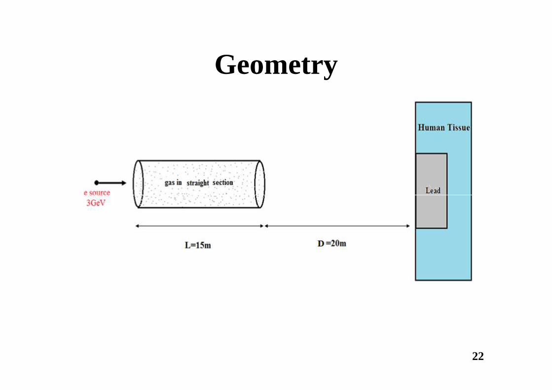
Geometry
22
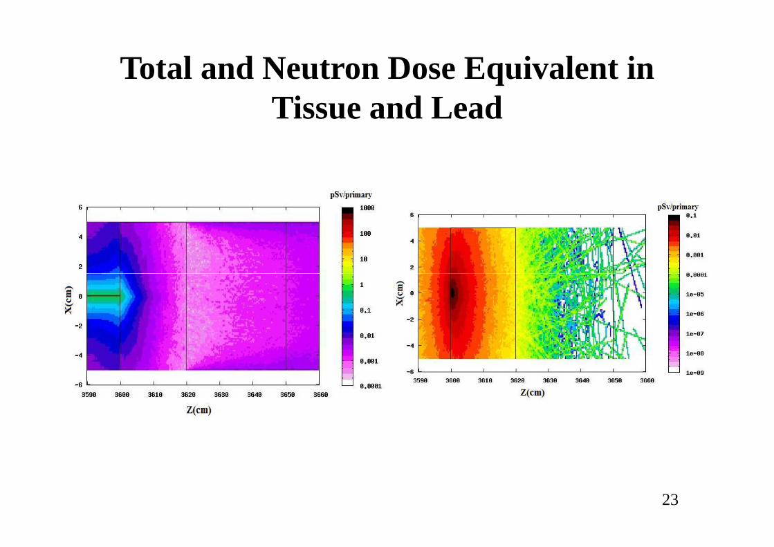
Total and Neutron Dose Equivalent in Tissue and Lead
23
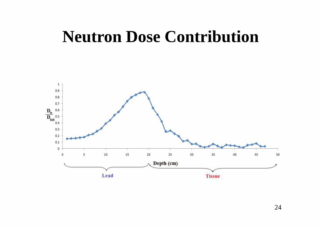
Neutron Dose Contribution
24
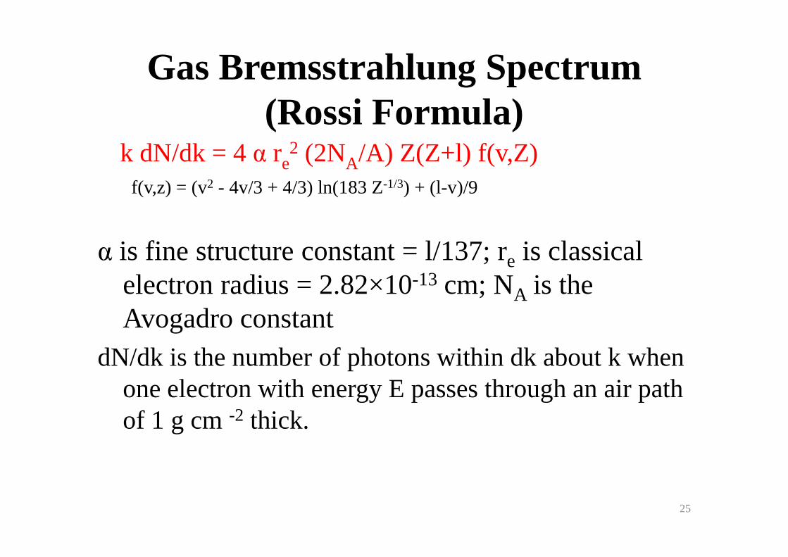
Gas Bremsstrahlung Spectrum (Rossi Formula)
α is fine structure constant = l/137; re is classical electron radius = 2.82×10⁻¹³ cm; N is the
k dN/dk = 4 α re2 (2NA/A) Z(Z+l) f(v,Z)
f(v,z) = (v2 - 4v/3 + 4/3) ln(183 Z-1/3) + (l-v)/9
electron radius = 2.82×10⁻¹³ cm; NA is the Avogadro constant
dN/dk is the number of photons within dk about k when one electron with energy E passes through an air path of 1 g cm -2 thick.
25
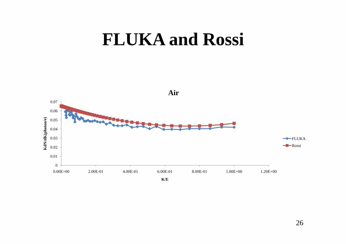
FLUKA and Rossi
0.05
0.06
0.07
(pho
ton/
e)
Air
0
0.01
0.02
0.03
0.04
0.05
0.00E+00 2.00E-01 4.00E-01 6.00E-01 8.00E-01 1.00E+00 1.20E+00
KdN
/dK
(pho
ton/
e
K/E
FLUKA
Rossi
26
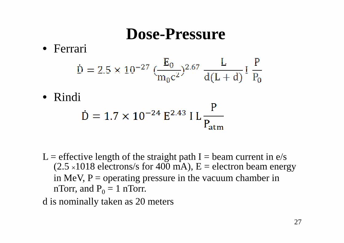
Dose-Pressure• Ferrari
• Rindi
L = effective length of the straight path I = beam current in e/s (2.5 ×10¹⁸ electrons/s for 400 mA), E = electron beam energy in MeV, P = operating pressure in the vacuum chamber in nTorr, and P0 = 1 nTorr.
d is nominally taken as 20 meters
27
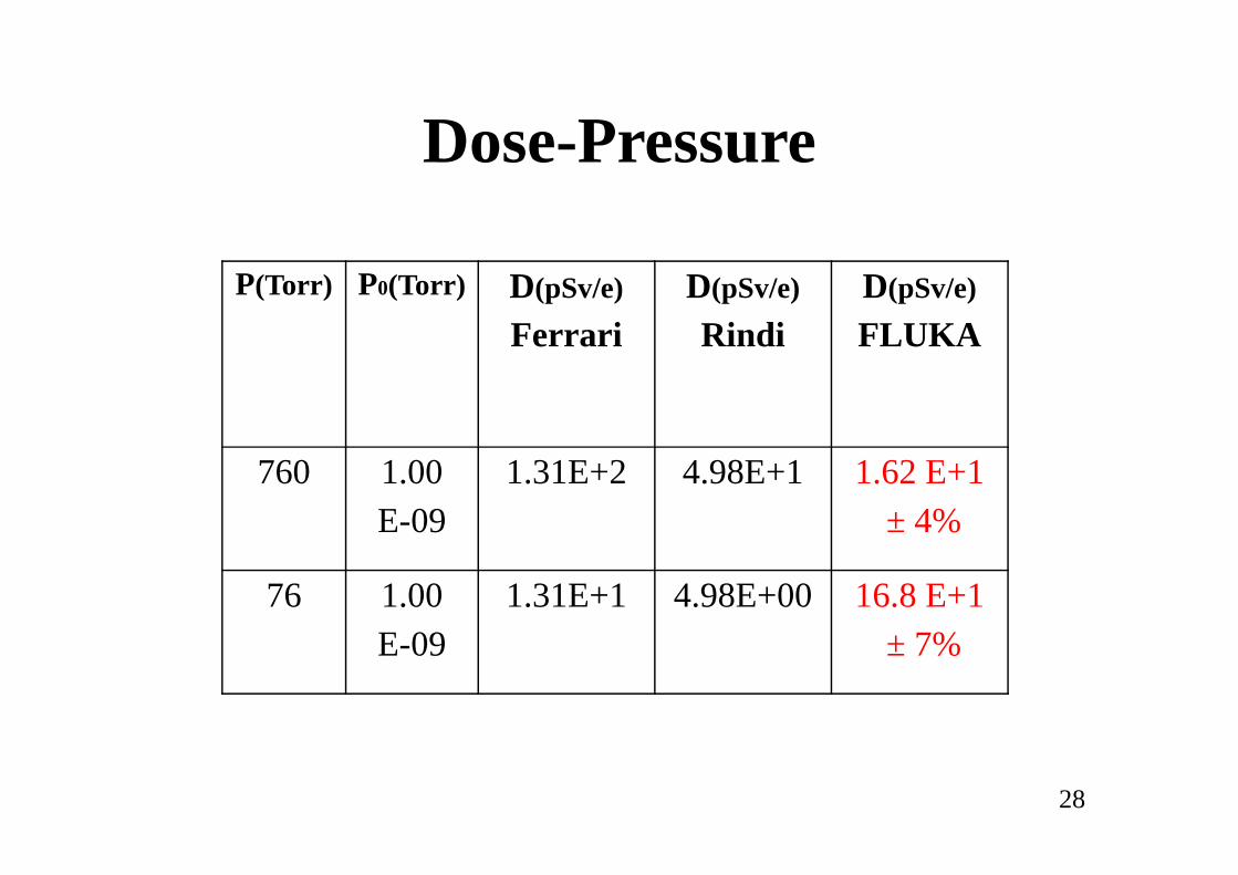
Dose-Pressure
P(Torr) P0(Torr) D(pSv/e)
FerrariD(pSv/e)
RindiD(pSv/e)
FLUKA
28
760 1.00E-09
1.31E+2 4.98E+1 1.62 E+1± 4%
76 1.00E-09
1.31E+1 4.98E+00 16.8 E+1± 7%
Shielding Calculation for ILSF Beam Stop, Analytical Methodand Monte Carlo Simulationand Monte Carlo Simulation
29
Beam Dump
• Beam Stop controls the beamin synchrotronaccelerator
• It is assumedall electrons are lostin these parts.
• Therefore it isthe worst casein radiation shieldingconsiderations.considerations.
• Bremsstrahlung radiationis produced when electronbeamstrikes stopper.
• If the bremsstrahlung photon energy is highenough, gas bremsstrahlung can produce neutrons viaphoto-neutron interaction.
30
31
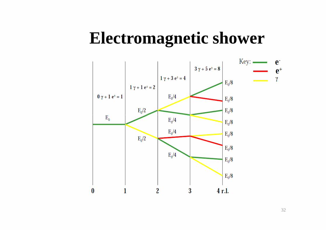
Electromagnetic shower
32
Electromagnetic shower
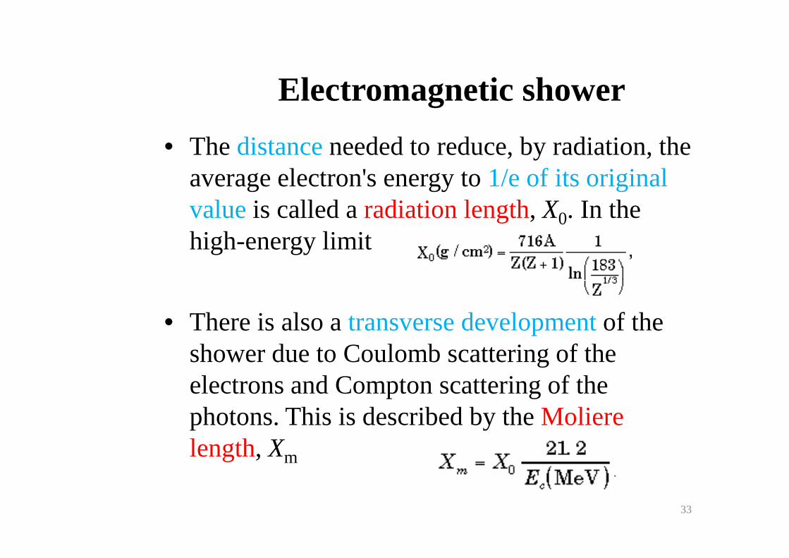
• The distanceneeded to reduce, by radiation, the average electron's energy to 1/e of its original valueis called a radiation length, X0. In the high-energy limit
• There is also a transverse development of the shower due to Coulomb scattering of the electrons and Compton scattering of the photons. This is described by the Moliere length, Xm
33
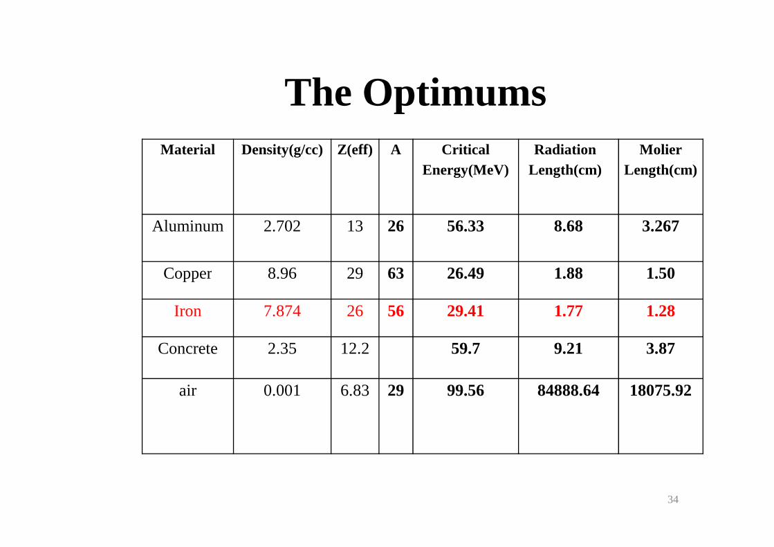
The OptimumsMaterial Density(g/cc) Z(eff) A Critical
Energy(MeV) Radiation
Length(cm) Molier
Length(cm)
Aluminum 2.702 13 26 56.33 8.68 3.267
Copper 8.96 29 63 26.49 1.88 1.50Copper 8.96 29 63 26.49 1.88 1.50
Iron 7.874 26 56 29.41 1.77 1.28
Concrete 2.35 12.2 59.7 9.21 3.87
air 0.001 6.83 29 99.56 84888.64 18075.92
34
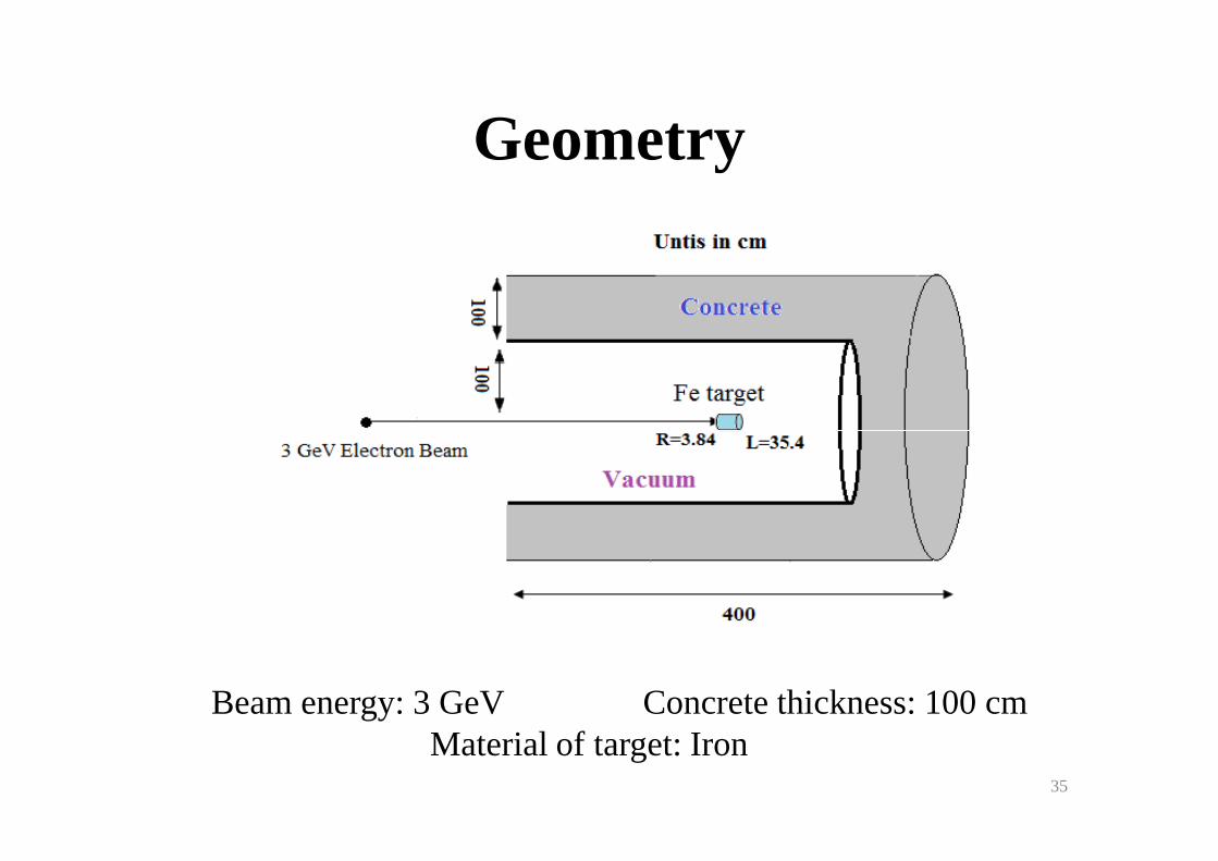
Geometry
Beam energy: 3 GeV Concrete thickness: 100 cm Material of target: Iron
35
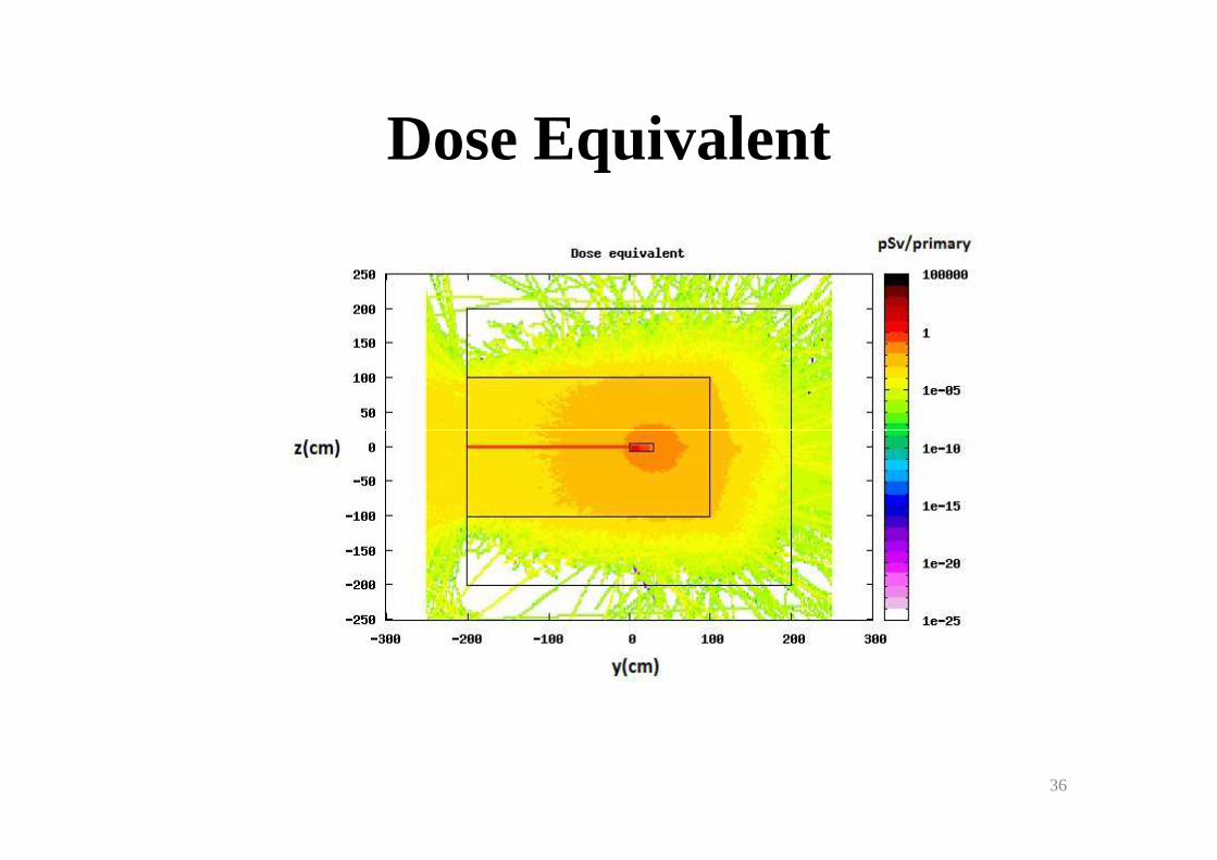
Dose Equivalent
36
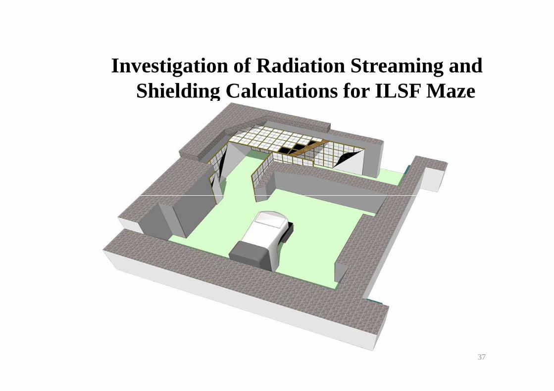
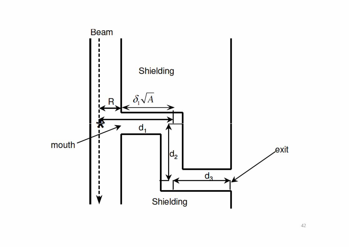
Investigation of Radiation Streaming and Shielding Calculations for ILSF Maze
37
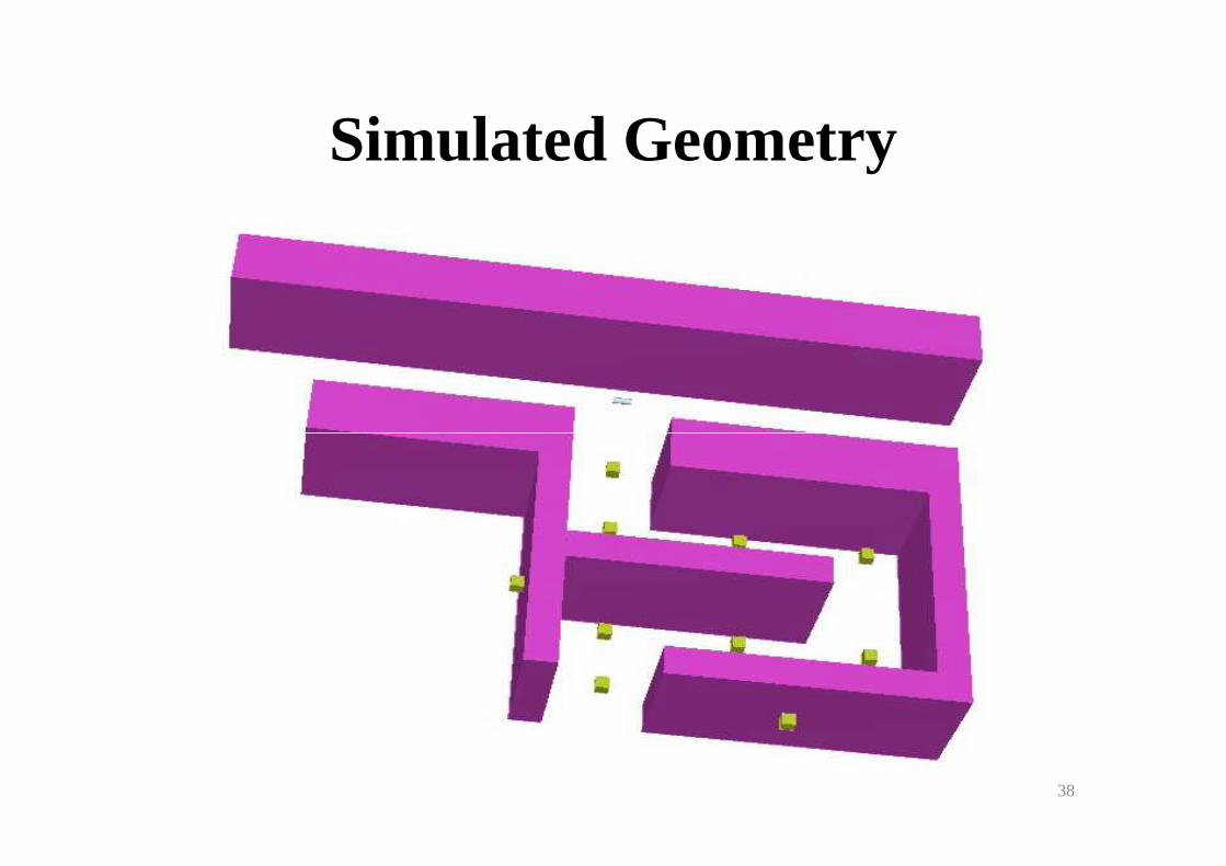
Simulated Geometry
38
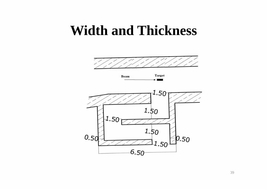
Width and Thickness
39
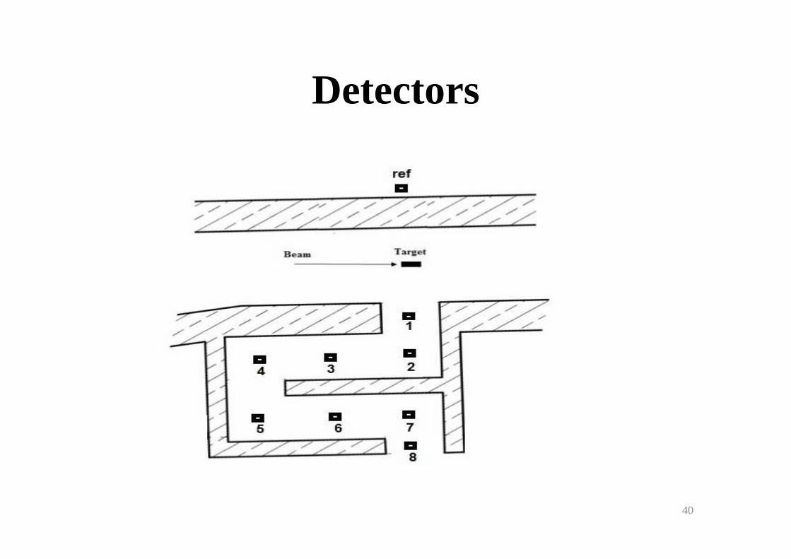
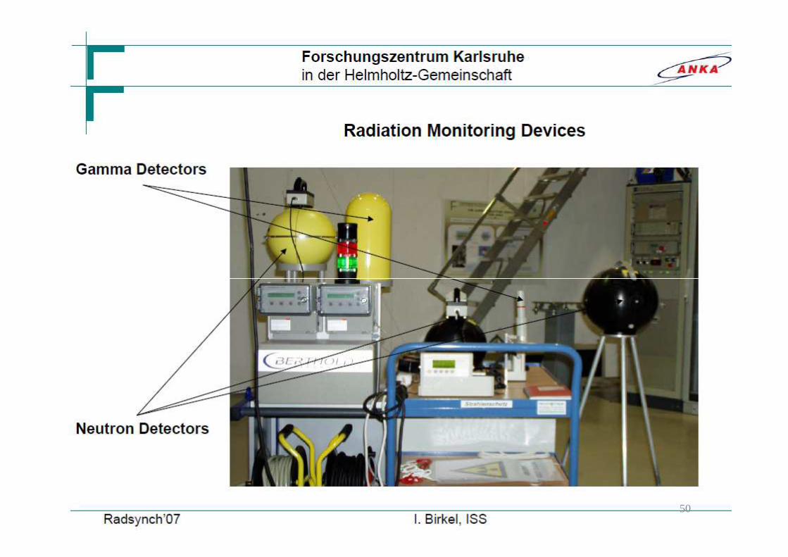
Detectors
40
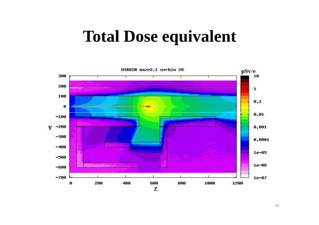
Total Dose equivalent
41
42

Photon and Neutron Doses At several Locations Along ILSF Maze
Location Photon(pSv/e) Neutron (pSv/e) Total (pSv/e)
Det. 1 6.58E-03 2.09E-03 8.67E-03Det. 2 8.45E-04 4.03E-04 1.25E-03Det. 3 6.77E-06 2.90E-05 3.57E-05
43
6.77E-06 2.90E-05 3.57E-05Det. 4 9.61E-07 6.28E-06 7.25E-06Det. 5 2.35E-07 2.86E-06 3.09E-06Det. 6 3.96E-07 3.12E-06 3.52E-06Det. 7 3.02E-06 5.07E-06 8.09E-06Det. 8 2.12E-06 3.63E-06 5.76E-06Det. Ref 9.10E-07 3.57E-06 4.48E4.48E--0606
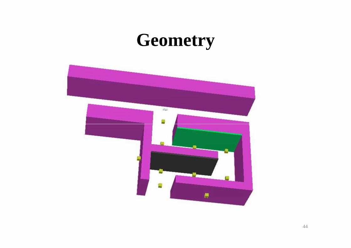
Geometry
44
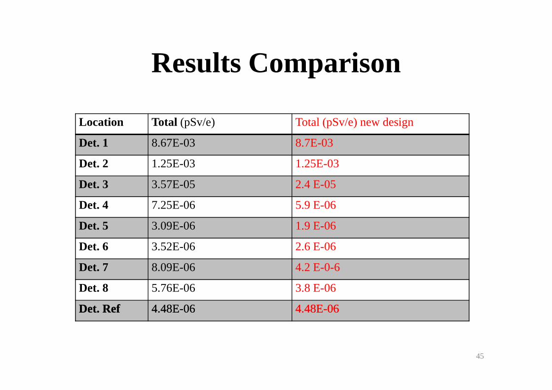
Results Comparison
Location Total (pSv/e) Total (pSv/e) new design
Det. 1 8.67E-03 8.7E-03
Det. 2 1.25E-03 1.25E-03
Det. 3 3.57E-05 2.4 E-05
45
Det. 4 7.25E-06 5.9 E-06
Det. 5 3.09E-06 1.9 E-06
Det. 6 3.52E-06 2.6 E-06
Det. 7 8.09E-06 4.2 E-0-6
Det. 8 5.76E-06 3.8 E-06
Det. RefDet. Ref 4.48E4.48E--0606 4.48E4.48E--0606
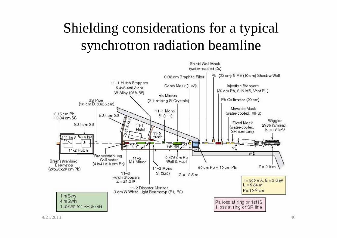
Shielding considerations for a typical synchrotron radiation beamline
9/21/2013 46
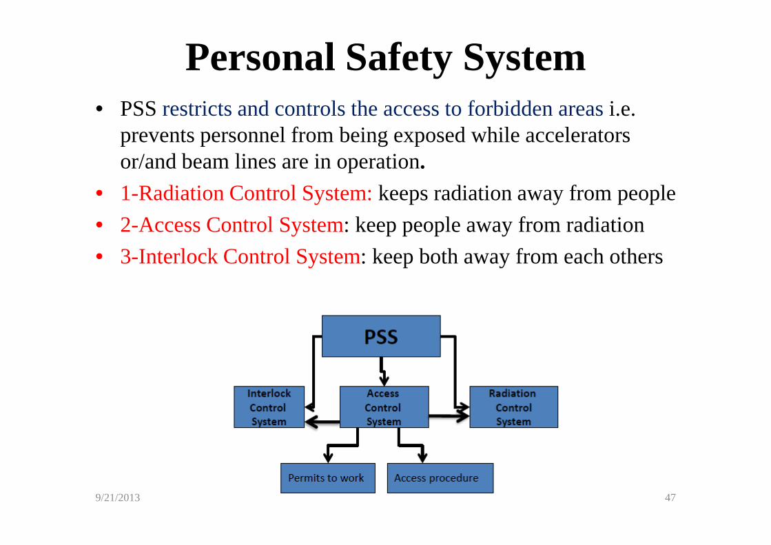
Personal Safety System • PSS restricts and controls the access to forbidden areas i.e.
prevents personnel from being exposed while accelerators or/and beam lines are in operation.
• 1-Radiation Control System: keeps radiation away from people
• 2-Access Control System: keep people away from radiation
• 3-Interlock Control System: keep both away from each others
9/21/2013 47
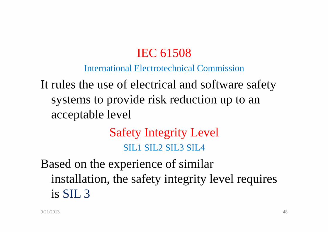
IEC 61508International Electrotechnical Commission
It rules the use of electrical and software safety systems to provide risk reduction up to an acceptable levelacceptable level
Safety Integrity LevelSIL1 SIL2 SIL3 SIL4
Based on the experience of similar installation, the safety integrity level requires is SIL 3
9/21/2013 48
9/21/2013 49
50
Thank you Thank you Thank you Thank you for for for for for for for for
your attentionyour attentionyour attentionyour attention
51