r-410a models: yc090 thru 300 yd120 thru 240 · r-410a models: yc090 thru 300 ... ld = low ambient...
TRANSCRIPT
R-410AMODELS: YC090 Thru 300
YD120 Thru 240
7.5 - 25 Ton
60 Hertz
430643-YIM-E-1010
TABLE OF CONTENTSNomenclature . . . . . . . . . . . . . . . . . . . . . . . . . . . . . . . . . . . . . 2General . . . . . . . . . . . . . . . . . . . . . . . . . . . . . . . . . . . . . . . . . . 2Renewal Parts . . . . . . . . . . . . . . . . . . . . . . . . . . . . . . . . . . . . . 3Agency Approvals . . . . . . . . . . . . . . . . . . . . . . . . . . . . . . . . . . 3Inspection . . . . . . . . . . . . . . . . . . . . . . . . . . . . . . . . . . . . . . . . 3
Physical Data . . . . . . . . . . . . . . . . . . . . . . . . . . . . . . . . . . . 4Installation . . . . . . . . . . . . . . . . . . . . . . . . . . . . . . . . . . . . . . . . 5
Preceding Installation . . . . . . . . . . . . . . . . . . . . . . . . . . . . . 5Limitations . . . . . . . . . . . . . . . . . . . . . . . . . . . . . . . . . . . . . . 5Location. . . . . . . . . . . . . . . . . . . . . . . . . . . . . . . . . . . . . . . . 5Clearances . . . . . . . . . . . . . . . . . . . . . . . . . . . . . . . . . . . . . 7Rigging . . . . . . . . . . . . . . . . . . . . . . . . . . . . . . . . . . . . . . . . 7
Phasing . . . . . . . . . . . . . . . . . . . . . . . . . . . . . . . . . . . . . . . . 8Electrical Data . . . . . . . . . . . . . . . . . . . . . . . . . . . . . . . . . . . 9Refrigerant Mains . . . . . . . . . . . . . . . . . . . . . . . . . . . . . . . 11Piping And Electrical Connections . . . . . . . . . . . . . . . . . . 21
Start-Up . . . . . . . . . . . . . . . . . . . . . . . . . . . . . . . . . . . . . . . . . 21Crankcase Heater . . . . . . . . . . . . . . . . . . . . . . . . . . . . . . . 21
Operation . . . . . . . . . . . . . . . . . . . . . . . . . . . . . . . . . . . . . . . 22Sequence of Operation . . . . . . . . . . . . . . . . . . . . . . . . . . . 22Cooling Sequence Of Operation . . . . . . . . . . . . . . . . . . . . 22Unit Control Board Option Setup. . . . . . . . . . . . . . . . . . . . 25
Troubleshooting . . . . . . . . . . . . . . . . . . . . . . . . . . . . . . . . . . 26Typical Wiring Diagrams . . . . . . . . . . . . . . . . . . . . . . . . . . . . 34
LIST OF TABLES1 YC090 - 300 and YD120 - 240 Physical Data . . . . . . . . . 42 Unit Application Data . . . . . . . . . . . . . . . . . . . . . . . . . . . . 53 Corner Weights & Center of Gravity . . . . . . . . . . . . . . . . 64 Minimum Clearances . . . . . . . . . . . . . . . . . . . . . . . . . . . . 75 Electrical Data - Outdoor Unit - AC Without Powered
Convenience Outlet . . . . . . . . . . . . . . . . . . . . . . . . . . . . . 96 Electrical Data - Outdoor Unit - AC With Powered
Convenience Outlet . . . . . . . . . . . . . . . . . . . . . . . . . . . . 10
7 YC090, YC/YD120, YC/YD150 Unit HeightDimensions . . . . . . . . . . . . . . . . . . . . . . . . . . . . . . . . . . 19
8 YC/YD180, YC/YD240 and YC300 Unit HeightDimensions . . . . . . . . . . . . . . . . . . . . . . . . . . . . . . . . . . 21
9 Piping And Electrical Connection Sizes (Inches) . . . . . . 2110 YC090 thru 300 Unit Control Board Flash Codes . . . . . 2411 YD120 thru 240 Unit Control Board Flash Codes . . . . . 24
LIST OF FIGURES1 Corner Weights & Center Of Gravity . . . . . . . . . . . . . . . . 62 Typical Rigging . . . . . . . . . . . . . . . . . . . . . . . . . . . . . . . . 73 Typical Field Wiring Diagram - NC090 Evaporator Unit
with YC090 Condenser Unit . . . . . . . . . . . . . . . . . . . . . . 134 Typical Field Wiring Diagram - NC120 thru 240 Evaporator
Unit with YC120 thru 240 Condenser Unit . . . . . . . . . . . 145 NC120 - 240 Liquid Line Solenoid Wiring . . . . . . . . . . . 146 Typical Field Wiring Diagram - ND120 thru 240 Air Handling
Unit with YD120 thru 240 Condensing Unit . . . . . . . . . . 157 Typical Field Wiring Diagram - Twin NC120 thru 240
Evaporator Units with 4-Pipe Condenser Unit . . . . . . . . 168 NC120 - 240 Liquid Line Solenoid Wiring . . . . . . . . . . . 169 Typical Field Wiring Diagram - Single 4-Pipe Evaporator
Unit with Twin Condenser Units . . . . . . . . . . . . . . . . . . . 1710 Typical Field Wiring Diagram - Twin NC090 Evaporator
Units with YD180 Condenser Unit . . . . . . . . . . . . . . . . . 1811 YC090, YC/YD120, YC/YD150 Unit Dimensions . . . . . . 1912 YC/YD180, YC/YD240 & YC300 Unit Dimensions and
Piping & Electrical Dimensions . . . . . . . . . . . . . . . . . . . 2013 Fan Orientation - Control Box End . . . . . . . . . . . . . . . . . 2414 Unit Control Board . . . . . . . . . . . . . . . . . . . . . . . . . . . . . 25
15 YC090 Charging Chart . . . . . . . . . . . . . . . . . . . . . . . . . . 2916 YC120 Charging Chart . . . . . . . . . . . . . . . . . . . . . . . . . . 2917 YD120 Charging Chart . . . . . . . . . . . . . . . . . . . . . . . . . . 3018 YC150 Charging Chart . . . . . . . . . . . . . . . . . . . . . . . . . . 3019 YD150 Charging Chart . . . . . . . . . . . . . . . . . . . . . . . . . . 3120 YC180 Charging Chart . . . . . . . . . . . . . . . . . . . . . . . . . . 3121 YD180 Charging Chart . . . . . . . . . . . . . . . . . . . . . . . . . . 3222 YC240 Charging Chart . . . . . . . . . . . . . . . . . . . . . . . . . . 3223 YD240 Charging Chart . . . . . . . . . . . . . . . . . . . . . . . . . . 3324 YC300 Charging Chart . . . . . . . . . . . . . . . . . . . . . . . . . . 3325 Typical YC090 Condensing Unit Wiring Diagram . . . . . 3426 Typical YC120 - 150 Condensing Unit Wiring
Diagram . . . . . . . . . . . . . . . . . . . . . . . . . . . . . . . . . . . . . 3527 Typical YD120 - 150 Condensing Unit Wiring
Diagram . . . . . . . . . . . . . . . . . . . . . . . . . . . . . . . . . . . . . 3628 Typical YC180 Condensing Unit Wiring Diagram . . . . . 3729 Typical YD180 - 240 Condensing Unit Wiring
Diagram . . . . . . . . . . . . . . . . . . . . . . . . . . . . . . . . . . . . . 3830 Typical YC240 Condensing Unit Wiring Diagram . . . . . 3931 Typical YC300 Condensing Unit Wiring Diagram . . . . . 40
430643-YIM-E-1010
2 Johnson Controls Unitary Products
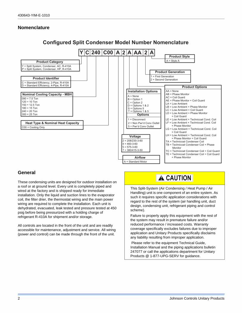
Nomenclature
General
These condensing units are designed for outdoor installation on a roof or at ground level. Every unit is completely piped and wired at the factory and is shipped ready for immediate installation. Only the liquid and suction lines to the evaporator coil, the filter drier, the thermostat wiring and the main power wiring are required to complete the installation. Each unit is dehydrated, evacuated, leak tested and pressure tested at 450 psig before being pressurized with a holding charge of refrigerant R-410A for shipment and/or storage.
All controls are located in the front of the unit and are readily accessible for maintenance, adjustment and service. All wiring (power and control) can be made through the front of the unit.
Product CategoryY = Split System, Condenser, AC, R-410A
Product IdentifierC = Standard Efficiency, 2-Pipe, R-410AD = Standard Efficiency, 4-Pipe, R-410A
Nominal Cooling Capacity - MBH090 = 7.5 Ton120 = 10 Ton150 = 12.5 Ton180 = 15 Ton240 = 20 Ton300 = 25 Ton
C00 = Cooling Only
Product OptionsAA = NoneAB = Phase MonitorAC = Coil GuardAE = Phase Monitor + Coil GuardLA = Low AmbientLB = Low Ambient + Phase MonitorLC = Low Ambient + Coil GuardLD = Low Ambient + Phase Monitor + Coil GuardLE = Low Ambient + Technicoat Cond. CoilLF = Low Ambient + Technicoat Cond. Coil + Phase MonitorLG = Low Ambient + Technicoat Cond. Coil + Coil GuardLH = Low Ambient + Technicoat Cond. Coil + Phase Monitor + Coil GuardTA = Technicoat Condenser CoilTB = Technicoat Condenser Coil + Phase MonitorTC = Technicoat Condenser Coil + Coil GuardTE = Technicoat Condenser Coil + Coil Guard + Phase Monitor
Installation OptionsA = None
2 = 208/230-3-604 = 460-3-605 = 575-3-607 = 380/415-3-50
Configured Split Condenser Model Number Nomenclature
A = Standard MotorAirflow
Product Generation1 = First Generation2 = Second Generation
Voltage
Heat Type & Nominal Heat Capacity
Y C 240 C00 A 2 A AA 2 AProduct Style
A = Style A
P = Split System, Condenser, HP, R-410A
2 = Non Pwr’d Conv Outlet1 = Disconnect
T = Options 1 & 5S = Options 5D = Options 1 & 2C = Option 2B = Option 1
Options
5 = Pwr’d Conv Outlet
This Split-System (Air Condensing / Heat Pump / Air Handling) unit is one component of an entire system. As such it requires specific application considerations with regard to the rest of the system (air handling unit, duct design, condensing unit, refrigerant piping and control scheme).
Failure to properly apply this equipment with the rest of the system may result in premature failure and/or reduced performance / increased costs. Warranty coverage specifically excludes failures due to improper application and Unitary Products specifically disclaims any liability resulting from improper application.
Please refer to the equipment Technical Guide, Installation Manual and the piping applications bulletin 247077 or call the applications department for Unitary Products @ 1-877-UPG-SERV for guidance.
430643-YIM-E-1010
Johnson Controls Unitary Products 3
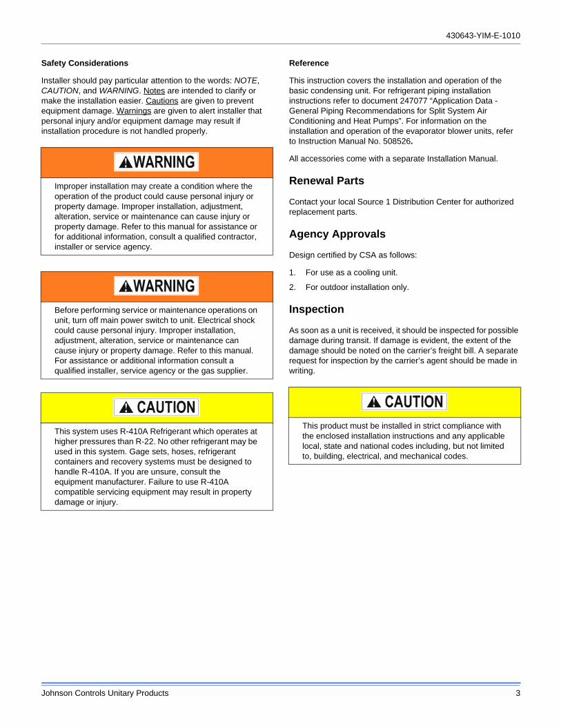
Safety Considerations
Installer should pay particular attention to the words: NOTE, CAUTION, and WARNING. Notes are intended to clarify or make the installation easier. Cautions are given to prevent equipment damage. Warnings are given to alert installer that personal injury and/or equipment damage may result if installation procedure is not handled properly.
Reference
This instruction covers the installation and operation of the basic condensing unit. For refrigerant piping installation instructions refer to document 247077 “Application Data - General Piping Recommendations for Split System Air Conditioning and Heat Pumps”. For information on the installation and operation of the evaporator blower units, refer to Instruction Manual No. 508526.
All accessories come with a separate Installation Manual.
Renewal Parts
Contact your local Source 1 Distribution Center for authorized replacement parts.
Agency Approvals
Design certified by CSA as follows:
1. For use as a cooling unit.
2. For outdoor installation only.
Inspection
As soon as a unit is received, it should be inspected for possible damage during transit. If damage is evident, the extent of the damage should be noted on the carrier’s freight bill. A separate request for inspection by the carrier’s agent should be made in writing.
Improper installation may create a condition where the operation of the product could cause personal injury or property damage. Improper installation, adjustment, alteration, service or maintenance can cause injury or property damage. Refer to this manual for assistance or for additional information, consult a qualified contractor, installer or service agency.
Before performing service or maintenance operations on unit, turn off main power switch to unit. Electrical shock could cause personal injury. Improper installation, adjustment, alteration, service or maintenance can cause injury or property damage. Refer to this manual. For assistance or additional information consult a qualified installer, service agency or the gas supplier.
This system uses R-410A Refrigerant which operates at higher pressures than R-22. No other refrigerant may be used in this system. Gage sets, hoses, refrigerant containers and recovery systems must be designed to handle R-410A. If you are unsure, consult the equipment manufacturer. Failure to use R-410A compatible servicing equipment may result in property damage or injury.
This product must be installed in strict compliance with the enclosed installation instructions and any applicable local, state and national codes including, but not limited to, building, electrical, and mechanical codes.
430643-YIM-E-1010
4 Johnson Controls Unitary Products
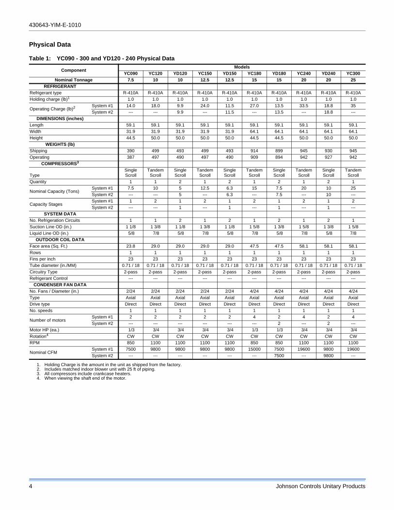
Physical Data
Table 1: YC090 - 300 and YD120 - 240 Physical Data
ComponentModels
YC090 YC120 YD120 YC150 YD150 YC180 YD180 YC240 YD240 YC300
Nominal Tonnage 7.5 10 10 12.5 12.5 15 15 20 20 25
REFRIGERANT
Refrigerant type R-410A R-410A R-410A R-410A R-410A R-410A R-410A R-410A R-410A R-410A
Holding charge (lb)1
1. Holding Charge is the amount in the unit as shipped from the factory.
1.0 1.0 1.0 1.0 1.0 1.0 1.0 1.0 1.0 1.0
Operating Charge (lb)2
2. Includes matched indoor blower unit with 25 ft of piping.
System #1 14.0 18.0 9.9 24.0 11.5 27.0 13.5 33.5 18.8 35
System #2 --- --- 9.9 --- 11.5 --- 13.5 --- 18.8 ---
DIMENSIONS (inches)
Length 59.1 59.1 59.1 59.1 59.1 59.1 59.1 59.1 59.1 59.1
Width 31.9 31.9 31.9 31.9 31.9 64.1 64.1 64.1 64.1 64.1
Height 44.5 50.0 50.0 50.0 50.0 44.5 44.5 50.0 50.0 50.0
WEIGHTS (lb)
Shipping 390 499 493 499 493 914 899 945 930 945
Operating 387 497 490 497 490 909 894 942 927 942
COMPRESSORS3
3. All compressors include crankcase heaters.
TypeSingle Scroll
Tandem Scroll
Single Scroll
Tandem Scroll
Single Scroll
Tandem Scroll
Single Scroll
Tandem Scroll
Single Scroll
Tandem Scroll
Quantity 1 1 2 1 2 1 2 1 2 1
Nominal Capacity (Tons)System #1 7.5 10 5 12.5 6.3 15 7.5 20 10 25
System #2 --- --- 5 --- 6.3 --- 7.5 --- 10 ---
Capacity StagesSystem #1 1 2 1 2 1 2 1 2 1 2
System #2 --- --- 1 --- 1 --- 1 --- 1 ---
SYSTEM DATA
No. Refrigeration Circuits 1 1 2 1 2 1 2 1 2 1
Suction Line OD (in.) 1 1/8 1 3/8 1 1/8 1 3/8 1 1/8 1 5/8 1 3/8 1 5/8 1 3/8 1 5/8
Liquid Line OD (in.) 5/8 7/8 5/8 7/8 5/8 7/8 5/8 7/8 5/8 7/8
OUTDOOR COIL DATA
Face area (Sq. Ft.) 23.8 29.0 29.0 29.0 29.0 47.5 47.5 58.1 58.1 58.1
Rows 1 1 1 1 1 1 1 1 1 1
Fins per inch 23 23 23 23 23 23 23 23 23 23
Tube diameter (in./MM) 0.71 / 18 0.71 / 18 0.71 / 18 0.71 / 18 0.71 / 18 0.71 / 18 0.71 / 18 0.71 / 18 0.71 / 18 0.71 / 18
Circuitry Type 2-pass 2-pass 2-pass 2-pass 2-pass 2-pass 2-pass 2-pass 2-pass 2-pass
Refrigerant Control --- --- --- --- --- --- --- --- --- ---
CONDENSER FAN DATA
No. Fans / Diameter (in.) 2/24 2/24 2/24 2/24 2/24 4/24 4/24 4/24 4/24 4/24
Type Axial Axial Axial Axial Axial Axial Axial Axial Axial Axial
Drive type Direct Direct Direct Direct Direct Direct Direct Direct Direct Direct
No. speeds 1 1 1 1 1 1 1 1 1 1
Number of motorsSystem #1 2 2 2 2 2 4 2 4 2 4
System #2 --- --- --- --- --- --- 2 --- 2 ---
Motor HP (ea.) 1/3 3/4 3/4 3/4 3/4 1/3 1/3 3/4 3/4 3/4
Rotation4
4. When viewing the shaft end of the motor.
CW CW CW CW CW CW CW CW CW CW
RPM 850 1100 1100 1100 1100 850 850 1100 1100 1100
Nominal CFMSystem #1 7500 9800 9800 9800 9800 15000 7500 19600 9800 19600
System #2 --- --- --- --- --- --- 7500 --- 9800 ---
430643-YIM-E-1010
Johnson Controls Unitary Products 5
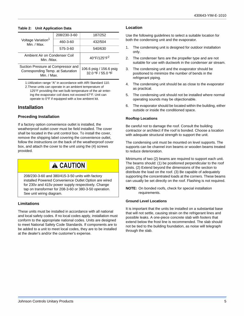
Installation
Preceding Installation
If a factory option convenience outlet is installed, the weatherproof outlet cover must be field installed. The cover shall be located in the unit control box. To install the cover, remove the shipping label covering the convenience outlet, follow the instructions on the back of the weatherproof cover box, and attach the cover to the unit using the (4) screws provided.
Limitations
These units must be installed in accordance with all national and local safety codes. If no local codes apply, installation must conform to the appropriate national codes. Units are designed to meet National Safety Code Standards. If components are to be added to a unit to meet local codes, they are to be installed at the dealer's and/or the customer's expense.
Location
Use the following guidelines to select a suitable location for both the condensing unit and the evaporator.
1. The condensing unit is designed for outdoor installation only.
2. The condenser fans are the propeller type and are not suitable for use with ductwork in the condenser air stream.
3. The condensing unit and the evaporator should be positioned to minimize the number of bends in the refrigerant piping.
4. The condensing unit should be as close to the evaporator as practical.
5. The condensing unit should not be installed where normal operating sounds may be objectionable.
6. The evaporator should be located within the building, either outside or inside the conditioned space.
Rooftop Locations
Be careful not to damage the roof. Consult the building contractor or architect if the roof is bonded. Choose a location with adequate structural strength to support the unit.
The condensing unit must be mounted on level supports. The supports can be channel iron beams or wooden beams treated to reduce deterioration.
Minimums of two (2) beams are required to support each unit. The beams should: (1) be positioned perpendicular to the roof joists. (2) Extend beyond the dimensions of the section to distribute the load on the roof. (3) Be capable of adequately supporting the concentrated loads at the corners. These beams can usually be set directly on the roof. Flashing is not required.
NOTE: On bonded roofs, check for special installation requirements.
Ground Level Locations
It is important that the units be installed on a substantial base that will not settle, causing strain on the refrigerant lines and possible leaks. A one-piece concrete slab with footers that extend below the frost line is recommended. The slab should not be tied to the building foundation, as noise will telegraph through the slab.
Table 2: Unit Application Data
Voltage Variation1
Min. / Max.
1.Utilization range “A” in accordance with ARI Standard 110.
208/230-3-60 187/252
460-3-60 432/504
575-3-60 540/630
Ambient Air on Condenser CoilMin. /Max. 40°F/125°F2
2.These units can operate in an ambient temperature of 125°F providing the wet bulb temperature of the air enter-ing the evaporator coil does not exceed 67°F. Unit can operate to 0°F if equipped with a low ambient kit.
Suction Pressure at Compressor andCorresponding Temp. at Saturation
Min. / Max.
106.6 psig / 156.6 psig32.0 ºF / 55.0 ºF
208/230-3-60 and 380/415-3-50 units with factory installed Powered Convenience Outlet Option are wired for 230v and 415v power supply respectively. Change tap on transformer for 208-3-60 or 380-3-50 operation. See unit wiring diagram.
430643-YIM-E-1010
6 Johnson Controls Unitary Products
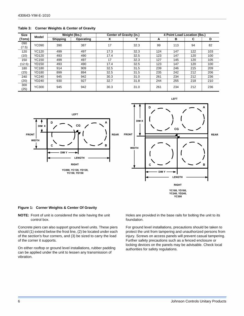
Figure 1: Corner Weights & Center Of Gravity
NOTE: Front of unit is considered the side having the unit control box.
Concrete piers can also support ground level units. These piers should (1) extend below the frost line, (2) be located under each of the section's four corners, and (3) be sized to carry the load of the corner it supports.
On either rooftop or ground level installations, rubber padding can be applied under the unit to lessen any transmission of vibration.
Holes are provided in the base rails for bolting the unit to its foundation.
For ground level installations, precautions should be taken to protect the unit from tampering and unauthorized persons from injury. Screws on access panels will prevent casual tampering. Further safety precautions such as a fenced enclosure or locking devices on the panels may be advisable. Check local authorities for safety regulations.
Table 3: Corner Weights & Center of Gravity
Size(Tons)
ModelWeight (lbs.) Center of Gravity (in.) 4 Point Load Location (lbs.)
Shipping Operating X Y A B C D090(7.5)
YC090 390 387 17 32.3 99 113 94 82
120(10)
YC120 499 497 17.3 32.3 124 147 122 103YD120 493 490 17.4 32.5 123 147 120 100
150(12.5)
YC150 499 497 17 32.3 127 145 120 105YD150 493 490 17.4 32.5 123 147 120 100
180(15)
YC180 914 909 32.5 31.5 239 246 215 209YD180 899 894 32.5 31.5 235 242 212 206
240(20)
YC240 945 942 30.3 31.0 261 234 212 236YD240 930 927 32.7 31.8 244 255 218 210
300(25)
YC300 945 942 30.3 31.0 261 234 212 236
DIM X
DIM Y
LENGTH
WIDTH
C
A
B
DCG
FRONT
RIGHT
REAR
LEFT
CG
DIM X
DIM Y
LENGTH
WIDTH
C B
AD
FRONT REAR
LEFT
RIGHT
YC090, YC120, YD120,YC150, YD150
YC180, YD180,YC240, YD240,
YC300
430643-YIM-E-1010
Johnson Controls Unitary Products 7
Clearances
The unit must be installed with sufficient clearance for air to enter the condenser coil, for air discharge and for servicing access. See Table 4 for clearances.
NOTE: Additional clearance is required to remove the compressors out the back of the unit, unless a means is available to lift the compressor out through the top of the unit.
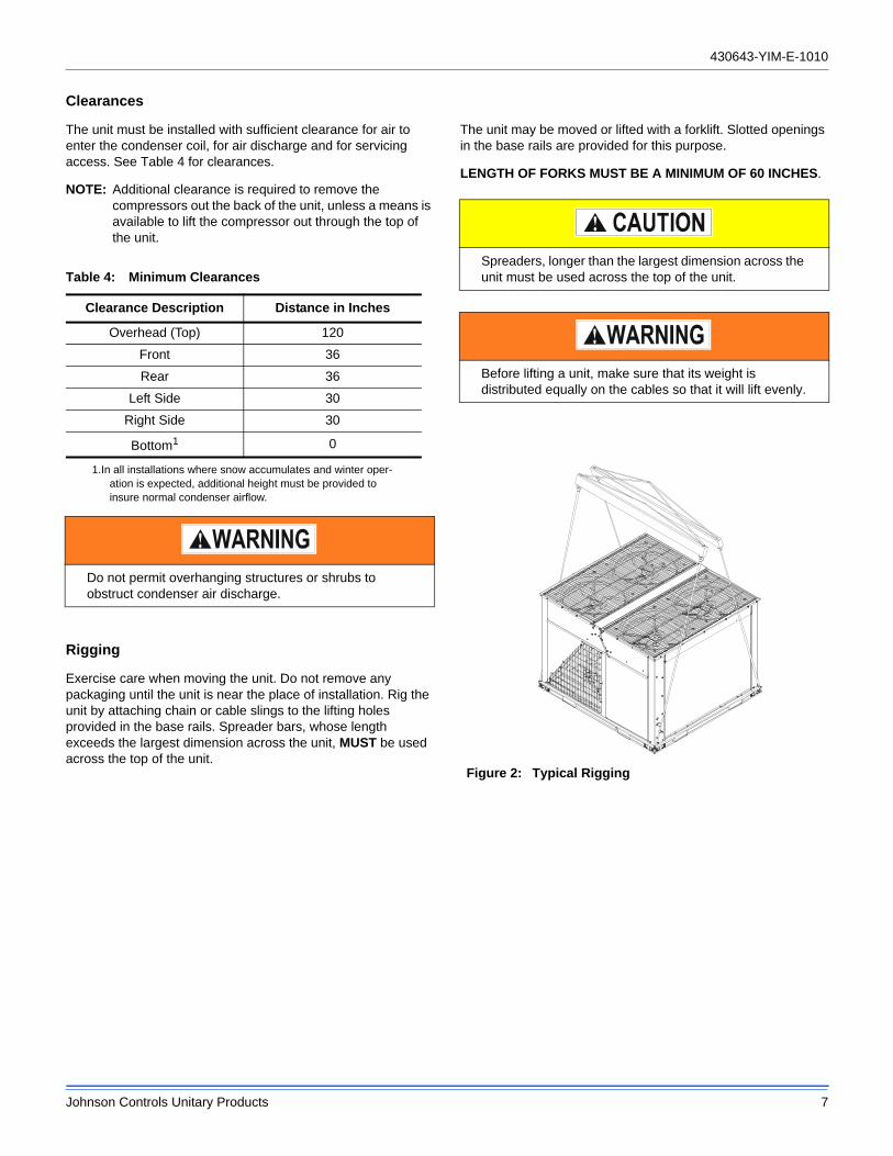
Rigging
Exercise care when moving the unit. Do not remove any packaging until the unit is near the place of installation. Rig the unit by attaching chain or cable slings to the lifting holes provided in the base rails. Spreader bars, whose length exceeds the largest dimension across the unit, MUST be used across the top of the unit.
The unit may be moved or lifted with a forklift. Slotted openings in the base rails are provided for this purpose.
LENGTH OF FORKS MUST BE A MINIMUM OF 60 INCHES.
Table 4: Minimum Clearances
Clearance Description Distance in Inches
Overhead (Top) 120
Front 36
Rear 36
Left Side 30
Right Side 30
Bottom1
1.In all installations where snow accumulates and winter oper-ation is expected, additional height must be provided to insure normal condenser airflow.
0
Do not permit overhanging structures or shrubs to obstruct condenser air discharge.
Spreaders, longer than the largest dimension across the unit must be used across the top of the unit.
Before lifting a unit, make sure that its weight is distributed equally on the cables so that it will lift evenly.
Figure 2: Typical Rigging
430643-YIM-E-1010
8 Johnson Controls Unitary Products
Power Wiring
Check the available power and the unit nameplate for correct voltage. Run the necessary number of properly sized wires to the unit. Provide a disconnect switch (if not included with the unit) and fusing as required (factory disconnect is a fused disconnect/breaker). Route the conduit through the large knockout located on the front of the electrical box. See Table 5 for Electrical Data.
The disconnect switch may be bolted to the side of the unit but not to any of the removable panels; this would interfere with access to the unit. Make sure that no refrigerant lines will be punctured when mounting the disconnect switch, and note that it must be suitable for outdoor installation.
Control Wiring
Route the necessary low voltage control wires from the Simplicity™ control board to the thermostat and also from the low voltage condenser unit control box to the terminal block inside the evaporator unit. Refer to Figures 3 thru 10 for field wiring diagrams.
Compressors
The scroll compressors used in this product are specifically designed to operate with R-410A Refrigerant and cannot be interchanged.
The compressor also uses a polyolester (POE oil), Mobil 3MA POE. This oil is extremely hydroscopic, meaning it absorbs water readily. POE oil can absorb 15 times as much water as other oils designed for HCFC and CFC refrigerants. Take all necessary precautions to avoid exposure of the oil to the atmosphere.
POE (polyolester) compressor lubricants are known to cause long term damage to some synthetic roofing materials.
Procedures which risk oil leakage include, but are not limited to, compressor replacement, repairing refrigerant leaks, replacing refrigerant components such as filter drier, pressure switch, metering device or coil.
Units are shipped with compressor mountings which are factory adjusted and ready for operation.
Phasing
Three-phase, scroll compressors operate in only one direction. If the scroll is drawing low amperage, has similar suction and discharge pressures, or is producing a high noise level, the scroll is misphased. Change the incoming line connection phasing to obtain the proper rotation.
All power and control wiring must be in accordance with National and Local electrical codes.
This system uses R-410A Refrigerant which operates at higher pressures than R-22. No other refrigerant may be used in this system.
Do not leave the system open to the atmosphere. Unit damage could occur due to moisture being absorbed by the POE oil in the system. This type of oil is highly susceptible to moisture absorption
Exposure, even if immediately cleaned up, may cause embrittlement (leading to cracking) to occur in one year or more. When performing any service that may risk exposure of compressor oil to the roof, take precautions to protect roofing.
Do not loosen compressor mounting bolts.
Scroll compressors require proper rotation to operate properly. Failure to check and correct rotation may result in property damage.
430643-YIM-E-1010
Johnson Controls Unitary Products 9
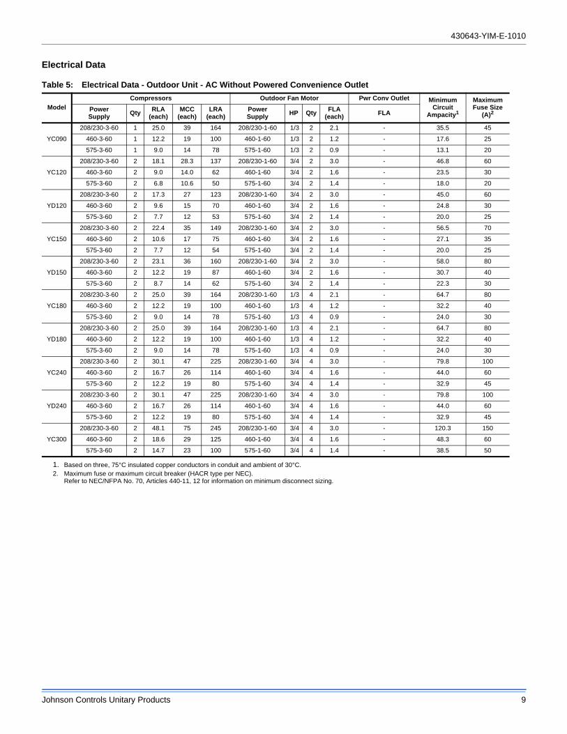
Electrical Data
Table 5: Electrical Data - Outdoor Unit - AC Without Powered Convenience Outlet
Model
Compressors Outdoor Fan Motor Pwr Conv Outlet MinimumCircuit
Ampacity1
MaximumFuse Size
(A)2PowerSupply
QtyRLA
(each)MCC
(each)LRA
(each)PowerSupply
HP QtyFLA
(each)FLA
YC090
208/230-3-60 1 25.0 39 164 208/230-1-60 1/3 2 2.1 - 35.5 45
460-3-60 1 12.2 19 100 460-1-60 1/3 2 1.2 - 17.6 25
575-3-60 1 9.0 14 78 575-1-60 1/3 2 0.9 - 13.1 20
YC120
208/230-3-60 2 18.1 28.3 137 208/230-1-60 3/4 2 3.0 - 46.8 60
460-3-60 2 9.0 14.0 62 460-1-60 3/4 2 1.6 - 23.5 30
575-3-60 2 6.8 10.6 50 575-1-60 3/4 2 1.4 - 18.0 20
YD120
208/230-3-60 2 17.3 27 123 208/230-1-60 3/4 2 3.0 - 45.0 60
460-3-60 2 9.6 15 70 460-1-60 3/4 2 1.6 - 24.8 30
575-3-60 2 7.7 12 53 575-1-60 3/4 2 1.4 - 20.0 25
YC150
208/230-3-60 2 22.4 35 149 208/230-1-60 3/4 2 3.0 - 56.5 70
460-3-60 2 10.6 17 75 460-1-60 3/4 2 1.6 - 27.1 35
575-3-60 2 7.7 12 54 575-1-60 3/4 2 1.4 - 20.0 25
YD150
208/230-3-60 2 23.1 36 160 208/230-1-60 3/4 2 3.0 - 58.0 80
460-3-60 2 12.2 19 87 460-1-60 3/4 2 1.6 - 30.7 40
575-3-60 2 8.7 14 62 575-1-60 3/4 2 1.4 - 22.3 30
YC180
208/230-3-60 2 25.0 39 164 208/230-1-60 1/3 4 2.1 - 64.7 80
460-3-60 2 12.2 19 100 460-1-60 1/3 4 1.2 - 32.2 40
575-3-60 2 9.0 14 78 575-1-60 1/3 4 0.9 - 24.0 30
YD180
208/230-3-60 2 25.0 39 164 208/230-1-60 1/3 4 2.1 - 64.7 80
460-3-60 2 12.2 19 100 460-1-60 1/3 4 1.2 - 32.2 40
575-3-60 2 9.0 14 78 575-1-60 1/3 4 0.9 - 24.0 30
YC240
208/230-3-60 2 30.1 47 225 208/230-1-60 3/4 4 3.0 - 79.8 100
460-3-60 2 16.7 26 114 460-1-60 3/4 4 1.6 - 44.0 60
575-3-60 2 12.2 19 80 575-1-60 3/4 4 1.4 - 32.9 45
YD240
208/230-3-60 2 30.1 47 225 208/230-1-60 3/4 4 3.0 - 79.8 100
460-3-60 2 16.7 26 114 460-1-60 3/4 4 1.6 - 44.0 60
575-3-60 2 12.2 19 80 575-1-60 3/4 4 1.4 - 32.9 45
YC300
208/230-3-60 2 48.1 75 245 208/230-1-60 3/4 4 3.0 - 120.3 150
460-3-60 2 18.6 29 125 460-1-60 3/4 4 1.6 - 48.3 60
575-3-60 2 14.7 23 100 575-1-60 3/4 4 1.4 - 38.5 50
1. Based on three, 75°C insulated copper conductors in conduit and ambient of 30°C.2. Maximum fuse or maximum circuit breaker (HACR type per NEC).
Refer to NEC/NFPA No. 70, Articles 440-11, 12 for information on minimum disconnect sizing.
430643-YIM-E-1010
10 Johnson Controls Unitary Products
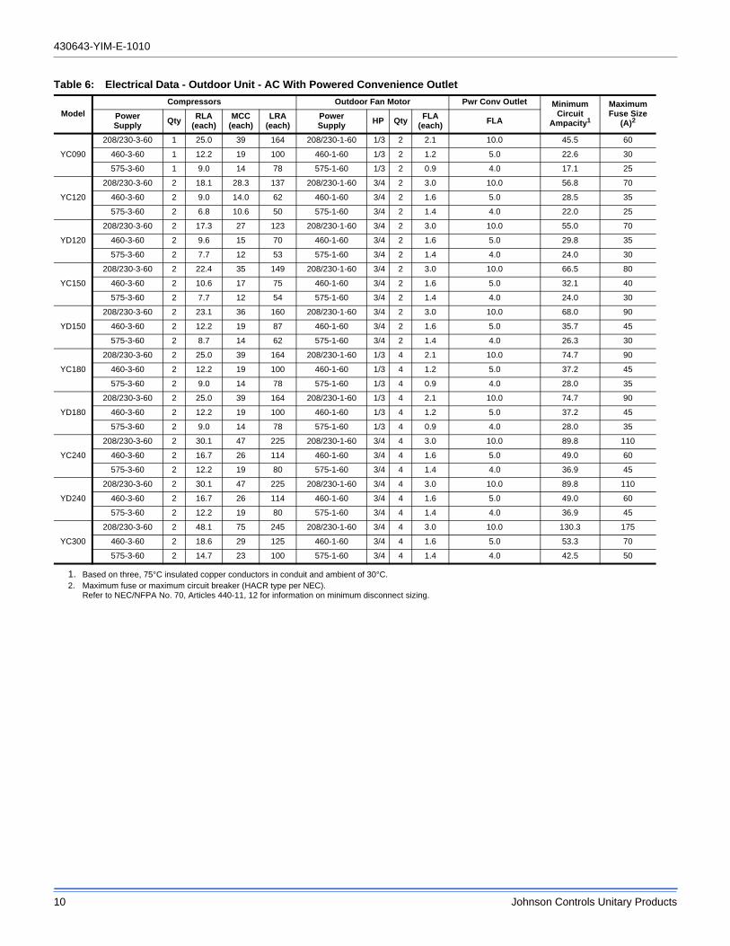
Table 6: Electrical Data - Outdoor Unit - AC With Powered Convenience Outlet
Model
Compressors Outdoor Fan Motor Pwr Conv Outlet MinimumCircuit
Ampacity1
MaximumFuse Size
(A)2PowerSupply
QtyRLA
(each)MCC
(each)LRA
(each)PowerSupply
HP QtyFLA
(each)FLA
YC090
208/230-3-60 1 25.0 39 164 208/230-1-60 1/3 2 2.1 10.0 45.5 60
460-3-60 1 12.2 19 100 460-1-60 1/3 2 1.2 5.0 22.6 30
575-3-60 1 9.0 14 78 575-1-60 1/3 2 0.9 4.0 17.1 25
YC120
208/230-3-60 2 18.1 28.3 137 208/230-1-60 3/4 2 3.0 10.0 56.8 70
460-3-60 2 9.0 14.0 62 460-1-60 3/4 2 1.6 5.0 28.5 35
575-3-60 2 6.8 10.6 50 575-1-60 3/4 2 1.4 4.0 22.0 25
YD120
208/230-3-60 2 17.3 27 123 208/230-1-60 3/4 2 3.0 10.0 55.0 70
460-3-60 2 9.6 15 70 460-1-60 3/4 2 1.6 5.0 29.8 35
575-3-60 2 7.7 12 53 575-1-60 3/4 2 1.4 4.0 24.0 30
YC150
208/230-3-60 2 22.4 35 149 208/230-1-60 3/4 2 3.0 10.0 66.5 80
460-3-60 2 10.6 17 75 460-1-60 3/4 2 1.6 5.0 32.1 40
575-3-60 2 7.7 12 54 575-1-60 3/4 2 1.4 4.0 24.0 30
YD150
208/230-3-60 2 23.1 36 160 208/230-1-60 3/4 2 3.0 10.0 68.0 90
460-3-60 2 12.2 19 87 460-1-60 3/4 2 1.6 5.0 35.7 45
575-3-60 2 8.7 14 62 575-1-60 3/4 2 1.4 4.0 26.3 30
YC180
208/230-3-60 2 25.0 39 164 208/230-1-60 1/3 4 2.1 10.0 74.7 90
460-3-60 2 12.2 19 100 460-1-60 1/3 4 1.2 5.0 37.2 45
575-3-60 2 9.0 14 78 575-1-60 1/3 4 0.9 4.0 28.0 35
YD180
208/230-3-60 2 25.0 39 164 208/230-1-60 1/3 4 2.1 10.0 74.7 90
460-3-60 2 12.2 19 100 460-1-60 1/3 4 1.2 5.0 37.2 45
575-3-60 2 9.0 14 78 575-1-60 1/3 4 0.9 4.0 28.0 35
YC240
208/230-3-60 2 30.1 47 225 208/230-1-60 3/4 4 3.0 10.0 89.8 110
460-3-60 2 16.7 26 114 460-1-60 3/4 4 1.6 5.0 49.0 60
575-3-60 2 12.2 19 80 575-1-60 3/4 4 1.4 4.0 36.9 45
YD240
208/230-3-60 2 30.1 47 225 208/230-1-60 3/4 4 3.0 10.0 89.8 110
460-3-60 2 16.7 26 114 460-1-60 3/4 4 1.6 5.0 49.0 60
575-3-60 2 12.2 19 80 575-1-60 3/4 4 1.4 4.0 36.9 45
YC300
208/230-3-60 2 48.1 75 245 208/230-1-60 3/4 4 3.0 10.0 130.3 175
460-3-60 2 18.6 29 125 460-1-60 3/4 4 1.6 5.0 53.3 70
575-3-60 2 14.7 23 100 575-1-60 3/4 4 1.4 4.0 42.5 50
1. Based on three, 75°C insulated copper conductors in conduit and ambient of 30°C.2. Maximum fuse or maximum circuit breaker (HACR type per NEC).
Refer to NEC/NFPA No. 70, Articles 440-11, 12 for information on minimum disconnect sizing.
430643-YIM-E-1010
Johnson Controls Unitary Products 11
Refrigerant Mains
Line Sizing
When sizing refrigerant pipe for a split-system air conditioner, check the following:
1. Suction line pressure drop due to friction.
2. Liquid line pressure drop due to friction.
3. Suction line velocity for oil return.
4. Liquid line pressure drop due to vertical rise. For certain piping arrangements, different sizes of suction line pipe may have to be used. The velocity of the refrigerant vapor must always be great enough to carry the oil back to the compressor.
5. Evaporator Located Below Condenser - On a split system where the evaporator blower is located below the condenser, the suction line must be sized for both pressure drop and for oil return.
6. Condenser Located Below Evaporator - When the condenser is located below the evaporator blower, the liquid line must be designed for the pressure drop due to both friction loss and vertical rise. If the pressure drop due to vertical rise and friction exceeds 60 psi, some refrigerant will flash before it reaches the thermal expansion valve.
Flash gas:
1. Increases the liquid line pressure loss due to friction that in turn causes further flashing.
2. Reduces the capacity of the refrigerant control device which starves the evaporator.
3. Erodes the seat of the refrigerant control device.
4. Causes erratic control of the refrigerant entering the evaporator.
Take Adequate Precautions
Many service problems can be avoided by taking adequate precautions to provide an internally clean and dry system and by using procedures and materials that conform to established standards.
Use hard drawn copper tubing where no appreciable amount of bending around pipes or other obstructions is necessary. If soft copper is used, care should be taken to avoid sharp bends that may cause a restriction. Pack fiberglass insulation and a sealing material such as permagum around refrigerant lines where they penetrate a wall to reduce vibrations and to retain some flexibility.
Support all tubing at minimum intervals with suitable hangers, brackets or clamps.
Braze all copper-to-copper joints with Silfos-5 or equivalent brazing material. Do not use soft solder. Insulate all suction lines with a minimum of 1/2" ARMAFLEX or equivalent that meets local codes. Liquid lines exposed to direct sunlight and/or high temperatures must also be insulated. Never solder suction and liquid lines together. They can be taped together for convenience and support purposes, but they must be completely insulated from each other.
The liquid and suction service ports on the condenser section permit leak testing, evacuation, and partial charging of the field piping and the evaporator without disturbing refrigerant stored in the condenser during initial installation.
Before beginning installation of the main lines, be sure that the evaporator section has not developed a leak in transit. Check pressure at the Schrader valve located on the header of each coil. If pressure still exists in the system, it can be assumed to be leak free. If pressure DOES NOT exist the section will need to be repaired before evacuation and charging is performed.
A filter-drier MUST be field-installed in the liquid line of every system to prevent dirt and moisture from damaging the system. Properly sized filter-driers are shipped with each condensing section.
NOTE: Installing a filter-drier does not eliminate the need for the proper evacuation of a system before it is charged.
A field-installed moisture indicating sight-glass should be installed in the liquid line(s) between the filter-drier and the evaporator coil. The moisture indicating sight-glass can be used to check for excess moisture in the system.
Both condenser and evaporator sections have copper sealing disks brazed over the end of liquid and suction connections. The temperature required to make or break a brazed joint is high enough to cause oxidation of the copper unless an inert atmosphere is provided.
NOTE: Dry nitrogen should flow through the system at all times when heat is being applied and until the joint has
This Split-System (Air Condensing / Heat Pump / Air Handling) unit is one component of an entire system. As such it requires specific application considerations with regard to the rest of the system (air handling unit, duct design, condensing unit, refrigerant piping and control scheme).
Failure to properly apply this equipment with the rest of the system may result in premature failure and/or reduced performance / increased costs. Warranty coverage specifically excludes failures due to improper application and Unitary Products specifically disclaims any liability resulting from improper application.
Please refer to the equipment Technical Guide, Installation Manual and the piping applications bulletin 247077 or call the applications department for Unitary Products @ 1-877-UPG-SERV for guidance.
430643-YIM-E-1010
12 Johnson Controls Unitary Products
cooled. The flow of nitrogen will prevent oxidation of the copper lines during installation.
Always punch a small hole in sealing disks before unbrazing to prevent the pressure in the line from blowing them off. Do not use a drill as copper shavings can enter system.
NOTE: Solenoid and hot gas bypass valves (if used) should be opened manually or electrically during brazing or evacuating.
NOTE: Schrader valves located on unit service valves should have their stem removed during brazing to prevent damage to the valve.
Start Installation
Start Installation of main lines at the condenser unit. Verify the service valves are fully seated by screwing the stem of both valves down into the valve body until it stops. Remove the Schrader valve stem and connect a low-pressure nitrogen source to the service port on the suction line valve body. Punch a small hole in the sealing disk; the flow of nitrogen will prevent any debris from entering the system. Wrap the valve body with a wet rag to prevent overheating during the brazing process. Overheating the valve will damage the valve seals. Unbraze the sealing disk, cool the valve body and prepare the joint for connections of the main lines. Repeat for the liquid line valve body.
Connect the main liquid line to the liquid line service valve on the condenser section, while maintaining a flow of nitrogen. Cool the valve body and replace the Schrader valve stem on the service port of the liquid line service valve.
Install the liquid line from the condenser unit to the evaporator liquid connection, maintaining a flow of nitrogen during all brazing operations.
The filter-drier and sight glass must be located in this line, leaving the O.D. unit.
Connect a low-pressure nitrogen source to the Schrader valve located on the evaporator unit coil headers. Punch a small hole in the sealing disks, the flow of nitrogen will prevent any debris from entering the system. Unbraze both liquid and suction
sealing disks and prepare the joints for connections of the main lines.
Connect the main liquid line to the liquid line connection on the evaporator unit, while maintaining a flow of nitrogen.
Make the suction line connection at the evaporator and run the line to the condenser unit. Connect the main suction line to the suction line service line on the condenser unit, while maintaining a flow of nitrogen. Cool the valve body and replace the Schrader valve stem on the service port of the suction line service valve.
Once the brazing process is complete, leak testing should be done on all interconnecting piping and the evaporator before proper evacuation to 500 microns is performed. Once the line set and evaporator unit is properly evacuated the service valves can be opened and the condenser unit is now ready to charge with the appropriate weight of refrigerant.
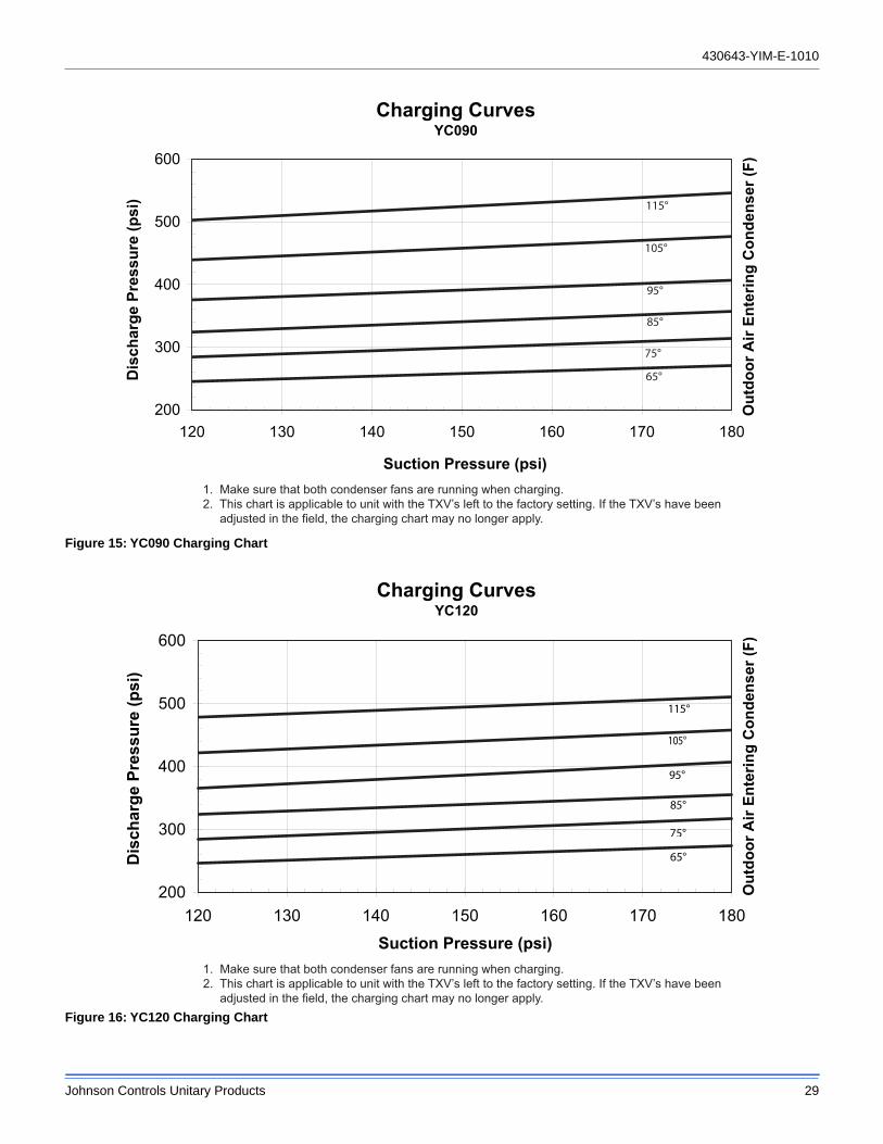
Calculate the correct system charge for the condenser unit, the evaporator unit and the field line set. Charge the system by introducing liquid refrigerant into the liquid line through the liquid port connection. Complete adding the refrigerant in vapor form into the suction port when the compressor is started.
The correct refrigerant pressures are indicated as shown in Figures 15 through 24.
NOTE: This instruction covers the installation and operation of the basic condenser unit. For refrigerant piping installation instructions refer to document 247077 "Application Data - General Piping Recommendations for Split System Air Conditioning and Heat Pumps".
Never remove a cap from an access port unless the valve is fully back-seated with its valve stem in the maximum counter-clockwise position because the refrigerant charge will be lost. Always use a refrigeration valve wrench to open and close these service valves.
This system uses R-410A Refrigerant which operates at higher pressures than R-22. No other refrigerant may be used in this system. Gage sets, hoses, refrigerant containers and recovery systems must be designed to handle R-410A. If you are unsure, consult the equipment manufacturer. Failure to use R-410A compatible servicing equipment may result in property damage or injury.
Wear safety glasses and gloves when handling refrigerants. Failure to follow this warning can cause serious personal injury.
430643-YIM-E-1010
Johnson Controls Unitary Products 13
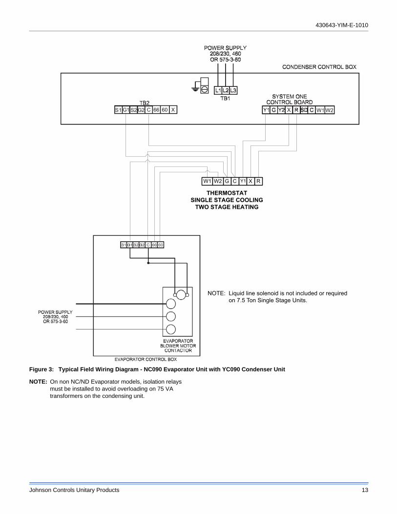
Figure 3: Typical Field Wiring Diagram - NC090 Evaporator Unit with YC090 Condenser Unit
NOTE: On non NC/ND Evaporator models, isolation relays must be installed to avoid overloading on 75 VA transformers on the condensing unit.
G C Y1 RW1 W2
THERMOSTATSINGLE STAGE COOLING
TWO STAGE HEATING
X
NOTE: Liquid line solenoid is not included or required on 7.5 Ton Single Stage Units.
430643-YIM-E-1010
14 Johnson Controls Unitary Products
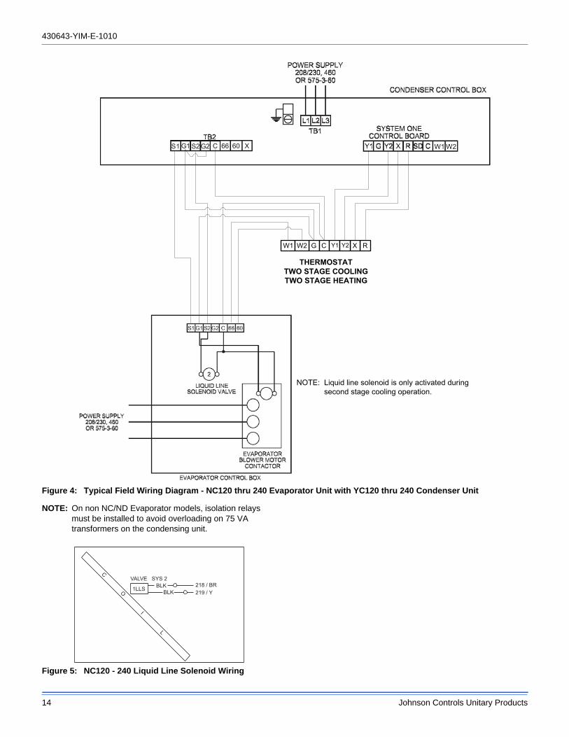
Figure 4: Typical Field Wiring Diagram - NC120 thru 240 Evaporator Unit with YC120 thru 240 Condenser Unit
NOTE: On non NC/ND Evaporator models, isolation relays must be installed to avoid overloading on 75 VA transformers on the condensing unit.
Figure 5: NC120 - 240 Liquid Line Solenoid Wiring
THERMOSTATTWO STAGE COOLINGTWO STAGE HEATING
G C Y1 RW1 W2 XY2
NOTE: Liquid line solenoid is only activated during second stage cooling operation.
219 / Y218 / BR
1LLS
VALVE SYS 2BLK
BLK
C O I L
430643-YIM-E-1010
Johnson Controls Unitary Products 15
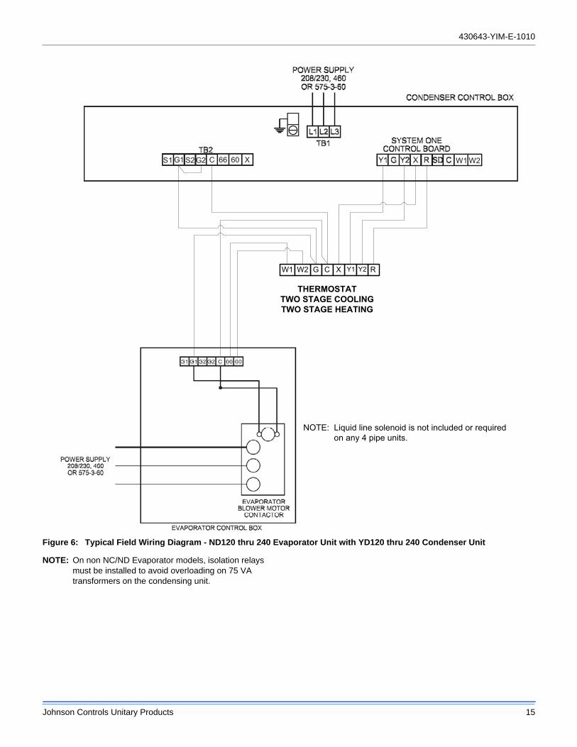
Figure 6: Typical Field Wiring Diagram - ND120 thru 240 Evaporator Unit with YD120 thru 240 Condenser Unit
NOTE: On non NC/ND Evaporator models, isolation relays must be installed to avoid overloading on 75 VA transformers on the condensing unit.
THERMOSTATTWO STAGE COOLINGTWO STAGE HEATING
G C Y1 RW1 W2 X Y2
NOTE: Liquid line solenoid is not included or required on any 4 pipe units.
430643-YIM-E-1010
16 Johnson Controls Unitary Products
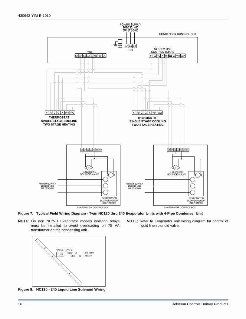
Figure 7: Typical Field Wiring Diagram - Twin NC120 thru 240 Evaporator Units with 4-Pipe Condenser Unit
NOTE: On non NC/ND Evaporator models isolation relays must be installed to avoid overloading on 75 VA transformer on the condensing unit.
Figure 8: NC120 - 240 Liquid Line Solenoid Wiring
NOTE: Refer to Evaporator unit wiring diagram for control of liquid line solenoid valve.
R CY1 G W1 R CY1 G W1
THERMOSTATSINGLE STAGE COOLING
TWO STAGE HEATING
W2 W2
THERMOSTATSINGLE STAGE COOLING
TWO STAGE HEATING
X X
219 / Y218 / BR
1LLS
VALVE SYS 2BLK
BLK
C O I L
430643-YIM-E-1010
Johnson Controls Unitary Products 17
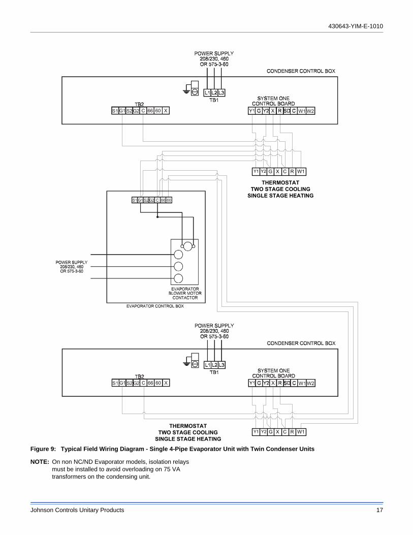
Figure 9: Typical Field Wiring Diagram - Single 4-Pipe Evaporator Unit with Twin Condenser Units
NOTE: On non NC/ND Evaporator models, isolation relays must be installed to avoid overloading on 75 VA transformers on the condensing unit.
RCY2 G W1
THERMOSTATTWO STAGE COOLING
SINGLE STAGE HEATING
RCY2 G W1THERMOSTAT
TWO STAGE COOLINGSINGLE STAGE HEATING
Y1
Y1
X
X
430643-YIM-E-1010
18 Johnson Controls Unitary Products
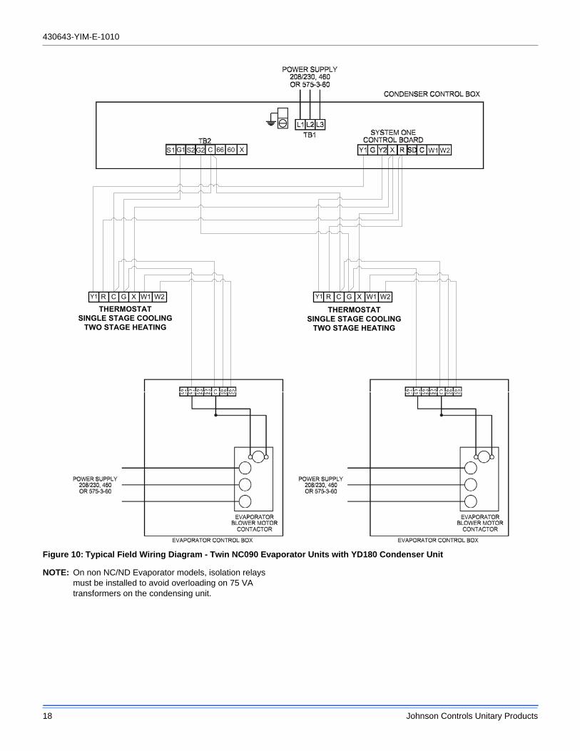
Figure 10: Typical Field Wiring Diagram - Twin NC090 Evaporator Units with YD180 Condenser Unit
NOTE: On non NC/ND Evaporator models, isolation relays must be installed to avoid overloading on 75 VA transformers on the condensing unit.
R CY1 G W1 R CY1 G W1
THERMOSTATSINGLE STAGE COOLING
TWO STAGE HEATING
W2 W2
THERMOSTATSINGLE STAGE COOLING
TWO STAGE HEATING
X X
430643-YIM-E-1010
Johnson Controls Unitary Products 19
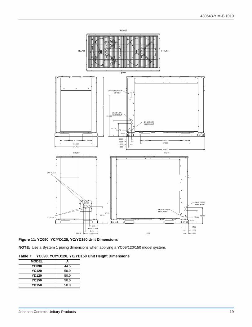
Figure 11: YC090, YC/YD120, YC/YD150 Unit Dimensions
NOTE: Use a System 1 piping dimensions when applying a YC09/120/150 model system.
Table 7: YC090, YC/YD120, YC/YD150 Unit Height DimensionsMODEL A
YC090 44.5
YC120 50.0
YD120 50.0
YC150 50.0
YD150 50.0
LEFT
REAR
RIGHT
FRONT
RIGHT
2X (Ø 0.875)KNOCKOUT
30.994
2X (Ø 1.375)KNOCKOUT
CONVENIENCEOUTLET
7.00010.000
24.000
31.758
7.0003.8833.6642.9331.664
23.00037.000
58.500
7.0007.000
12.1269.876
4.751
A
2X (Ø 1.375)KNOCKOUT
REAR LEFT
2X (Ø 0.875)KNOCKOUT
12.00010.000
4.875
4.132
2.382
1.882
15.5312.70
6.267.52
8.9810.60
SYSTEM 2
SYSTEM 1
FRONT
430643-YIM-E-1010
20 Johnson Controls Unitary Products
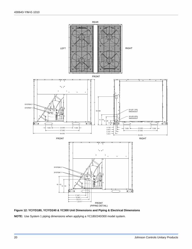
Figure 12: YC/YD180, YC/YD240 & YC300 Unit Dimensions and Piping & Electrical Dimensions
NOTE: Use System 1 piping dimensions when applying a YC180/240/300 model system.
LEFT RIGHT
FRONT
REAR
FRONT
FRONT(PIPING DETAIL)
RIGHT
SYSTEM 2
SYSTEM 1
7.0007.000 23.000
37.000
64.000
2X (Ø 0.875)KNOCKOUT
2X (Ø 1.375)KNOCKOUT
7.0007.000 23.00037.000
59.000
30.994
11.3759.125
4.750
4.1323.9133.1811.913
A
SYSTEM 2
SYSTEM 1
16.13313.133
17.36718.86720.617
22.617
430643-YIM-E-1010
Johnson Controls Unitary Products 21
YC3
Piping And Electrical Connections
Piping connections are made from the rear of 7.5 thru 12.5 Ton units and the front of 15 thru 25 Ton units. Connections can be made directly to the suction and liquid line service valves. Piping can be routed to the units from the left or right side.
Electrical connections for power and control wiring are made from the right or left side of all units. See Table 15 and Figures 8 and 11 for piping sizes and electrical knockout details.
Start-Up
Crankcase Heater
The crankcase heater must be energized at least 8 hours before starting the compressor. To energize the crankcase heater, the main disconnect switch must be closed. During this 8 hour period, the system switch on the room thermostat must be “OFF” to prevent the compressor from starting. Make sure that the bottom of the compressor is warm to the touch to prove crankcase heater operation.
Pre-Start Check
Before starting the unit, complete the following check list:
1. Have sufficient clearances been provided?
2. Has all foreign matter been removed from the interior of the unit (tools, construction or shipping materials, etc.)?
3. Have the condenser fans been rotated manually to check for free rotation?
4. Are all wiring connections tight?
5. Does the available power supply agree with the nameplate data on the unit?
6. Is the control circuit transformer set for the proper voltage?
7. Have the fuses, disconnect switch and power wire been sized properly?
8. Are all compressor hold-down nuts properly secured?
9. Are any refrigerant lines touching each other or any sheet metal surface? Rubbing due to vibration could cause a refrigerant leak.
10. Are there any visible signs of a refrigerant leak, such as oil residue?
11. Has the refrigeration system been leak checked, evacuated and had the correctly calculated charge weighted in?
12. Is any electrical wire laying against a hot refrigerant line?
Initial Start-Up
1. Supply power to the unit through the disconnect switch at least 8 hours prior to starting the compressor.
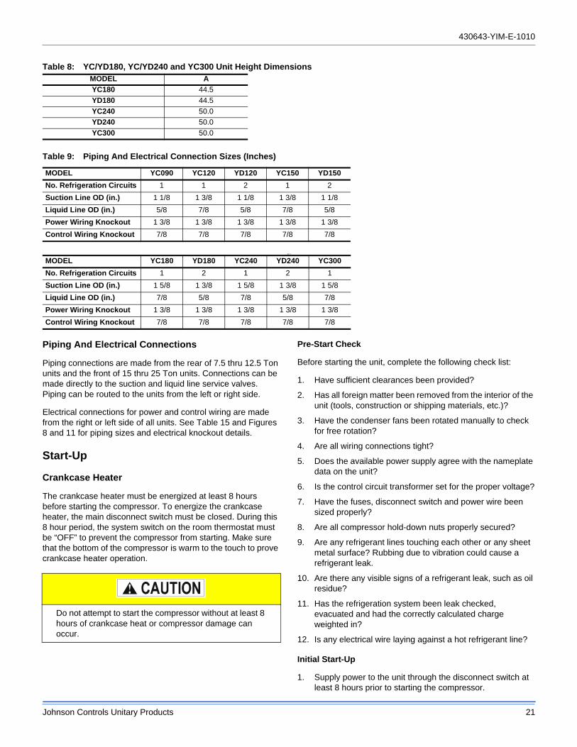
Table 8: YC/YD180, YC/YD240 and YC300 Unit Height DimensionsMODEL A
YC180 44.5
YD180 44.5
YC240 50.0
YD240 50.0
YC300 50.0
Table 9: Piping And Electrical Connection Sizes (Inches)
MODEL YC090 YC120 YD120 YC150 YD150
No. Refrigeration Circuits 1 1 2 1 2
Suction Line OD (in.) 1 1/8 1 3/8 1 1/8 1 3/8 1 1/8
Liquid Line OD (in.) 5/8 7/8 5/8 7/8 5/8
Power Wiring Knockout 1 3/8 1 3/8 1 3/8 1 3/8 1 3/8
Control Wiring Knockout 7/8 7/8 7/8 7/8 7/8
MODEL YC180 YD180 YC240 YD240 YC300
No. Refrigeration Circuits 1 2 1 2 1
Suction Line OD (in.) 1 5/8 1 3/8 1 5/8 1 3/8 1 5/8
Liquid Line OD (in.) 7/8 5/8 7/8 5/8 7/8
Power Wiring Knockout 1 3/8 1 3/8 1 3/8 1 3/8 1 3/8
Control Wiring Knockout 7/8 7/8 7/8 7/8 7/8
Do not attempt to start the compressor without at least 8 hours of crankcase heat or compressor damage can occur.
430643-YIM-E-1010
22 Johnson Controls Unitary Products
2. Move the system switch on the thermostat to the AUTO or COOL position.
3. Reduce the setting of the room thermostat to energize the compressor.
4. Check the operation of the evaporator unit per the manufacturer’s recommendations.
5. With an ammeter, check the compressor amps against the unit data plate.
6. Check for refrigerant leaks.
7. Check for any abnormal noises and/or vibrations, and make the necessary adjustments to correct fan blade(s) touching shroud, refrigerant lines hitting on sheet metal, etc.
8. After the unit has been operating for several minutes, shut off the main power supply at the disconnect switch and inspect all factory wiring connections and bolted surfaces for tightness.
Operation
Unit Control Overview
These series of condenser unit, come factory equipped with Simplicity™ controls to monitor all unit functionality and safety controls.
Safety Controls
The Simplicity™ control board incorporates features to monitor safety circuits as well as minimize compressor wear and damage. An anti-short cycle delay (ASCD) is utilized to prevent operation of a compressor too soon after its previous run. Additionally, a minimum run time is imposed anytime a compressor is energized to allow proper oil return to the compressor. The ASCD is initiated on unit start-up and on any compressor reset or lockout.
The Simplicity™ control board monitors the following inputs for each cooling system:
• A high-pressure switch is factory installed to protect against excessive discharge pressure due to a blocked condenser coil or a condenser fan motor failure. During cooling operation, if a high-pressure limit switch opens, the Simplicity™ control board will de-energize the associated compressors and initiate the 5-minute ASCD. If the call for cool is still present at the end of the ASCD, the control board will re-energize the halted compressor. If a high-pressure switch opens three times within two hours of operation, the Simplicity™ control board will lockout the associated system compressors and will flash an error code (See Table 11).
• A low-pressure switch to protect the unit against excessively low suction pressure is standard on all condensing units. If the low-pressure switch opens during normal operation, the Simplicity™ control board will de-energize the compressor, initiate the ASCD, and shut
down the condenser fans. On startup, if the low-pressure switch opens, the Simplicity™ control board will monitor the low-pressure switch to make sure it closes within one minute. If it fails to close, the unit will shut down the associated compressor and begin an ASCD. If the call for cool is still present at the end of the anti-short cycle time delaying, the control board will re-energize the halted compressor. If a low-pressure switch opens three times within one hour of operation, the Simplicity™ control board will lock-out the associated compressor and flash an error code (See Table 11).
• An ambient air switch will lock out mechanical cooling at 40F. A factory equipped low ambient option allows the unit to operate down to 0F. A field installed low ambient kit is also available.
The refrigerant systems are independently monitored and controlled. On any fault, only the associated system will be affected by any safety/preventive action. The other refrigerant system will continue to operate unless it is affected by the fault as well.
Sequence of Operation
Continuous Blower
By setting the room thermostat to “ON,” the low voltage control circuit from the “R” to “G” is completed and the supply air blower will operate continuously.
Intermittent Blower
With the room thermostat fan switch set to “AUTO” and the system switch set to either the “AUTO” or “HEAT” settings, the blower is energized whenever a cooling or heating operation is requested. The blower is energized after any specified delay associated with the operation.
When energized in cooling mode, the indoor blower has a minimum run time of 30 seconds. Additionally, the indoor blower has a delay of 10 seconds between operations.
Cooling Sequence Of Operation
Single-Stage Condenser Unit (YC090)
A single stage cooling thermostat is required to operate the condenser unit.
When the thermostat calls for cooling (Y1), the Simplicity control board (UCB) closes the coils of relay RY1 and contactors M1 and M3.
• Relay RY1 controls the crankcase heater (CCH1). The normally closed contacts allow CCH1 to operate during unit shutdown.
• Contactor M1 controls compressor COMPR1.
• Contactor M3 controls outdoor fans ODFAN1 & 2.
After completing the specified time for fan on-delay, UCB closes the coil of relay BR1.
430643-YIM-E-1010
Johnson Controls Unitary Products 23
• Relay BR1 sends a 24V signal to G1 of terminal block TB2. It may be used to control operation of an indoor blower.
When the call for cooling (Y1) is satisfied, the UCB disables the signal to RY1, M1 and M3 as long as the specified minimum run time (ASCD) has elapsed.
The UCB disables the signal to BR1 after completing the fan off-delay period.
Dual Stage Condenser Unit (YC120-300 or YD120-150)
A two stage cooling thermostat is required to operate the condenser unit.
• When the thermostat calls for first-stage cooling (Y1), the Simplicity control board (UCB) closes the coils of relays RY1 and BR1 and contactor M1.
• Relay RY1 has three functions. 1) control the crankcase heater CCH1, 2) control the coil of contactor M3 and 3) control the 24V output signal to S1 on terminal block TB2.
• Relay BR1 sends a 24V signal to G1 of terminal block TB2. It may be used to control operation of an indoor blower.
• Contactor M1 controls compressor COMPR1.
• Contactor M3 controls all outdoor fans.
When the thermostat calls for second-stage cooling (Y2), the Simplicity control board (UCB) closes the coils of relays RY2 and BR2 and contactor M2.
• Relay RY2 has three functions. 1) control the crankcase heater CCH2, 2) control the coil of contactor M3 and 3) control the 24V output signal to S2 on terminal block TB2.
• Relay BR2 sends a 24V signal to G2 of terminal block TB2. It may be used to control operation of an indoor blower.
• Contactor M2 controls compressor COMPR2.
If the initial call for cooling requires both stages (Y1 and Y2), the UCB will delay the second stage by 30 seconds to avoid an excessive power inrush.
NOTE: For lead-lag compressor operation, the jumper between terminals G1 and G2 on terminal block TB2 must remain in place to assure proper blower operation.
When the call for cooling (Y2) is satisfied, the UCB disables the signal to RY2, BR2, and M2 as long as the specified minimum run time (ASCD) has elapsed.
When the call for cooling (Y1) is satisfied, the UCB disables the signal to RY1, BR1 and M1 as long as the specified minimum run time (ASCD) has elapsed.
Dual Stage Condenser Unit (YD180-240)
A two stage cooling thermostat is required to operate the condenser unit.
When the thermostat calls for first-stage cooling (Y1), the Simplicity control board (UCB) closes the coils of relays RY1 and BR1 and contactor M1.
• Relay RY1 has three functions. 1) control the crankcase heater CCH1, 2) control the coil of contactor M3 and 3) control the 24V output signal to S1 on terminal block TB2.
• Relay BR1 sends a 24V signal to G1 of terminal block TB2. It may be used to control operation of an indoor blower.
• Contactor M1 controls compressor COMPR1.
• Contactor M3 controls outdoor fans ODFAN1 & 2.
When the thermostat calls for second-stage cooling (Y2), the Simplicity control board (UCB) closes the coils of relays RY2 and BR2 and contactor M2.
• Relay RY2 has three functions. 1) control the crankcase heater CCH2, 2) control the coil of contactor M4 and 3) control the 24V output signal to S2 on terminal block TB2.
• Relay BR2 sends a 24V signal to G2 of terminal block TB2. It may be used to control operation of an indoor blower.
• Contactor M2 controls compressor COMPR2.
• Contactor M4 controls outdoor fans ODFAN3 & 4.
If the initial call for cooling requires both stages (Y1 and Y2), the UCB will delay the second stage by 30 seconds to avoid an excessive power inrush.
NOTE: For lead-lag compressor operation, the jumper between terminals G1 and G2 on terminal block TB2 must remain in place to assure proper blower operation.
When the call for cooling (Y2) is satisfied, the UCB disables the signal to RY2, BR2, and M2 as long as the specified minimum run time (ASCD) has elapsed.
When the call for cooling (Y1) is satisfied, the UCB disables the signal to RY1, BR1 and M1 as long as the specified minimum run time (ASCD) has elapsed.
Low Ambient Cooling
These units are factory equipped with low ambient switches that work through the Simplicity control board to operate the compressors and condenser fans normally to 40ºF ambient temperature. The Electronic Low Ambient Controller 2LA04703000 Accessory is designed to assure safe operation through condenser head pressure regulation down to 0ºF ambient temperature.
Low Ambient Control Operation
• A call for cooling closes contactor M3 which energizes all condenser fans. The Low Ambient Control starts all fans at full speed then adjusts according to the liquid line temperature.
Refer to the appropriate 2LA low ambient kit instructions for additional detail on the factory or field installed low ambient kit and its operation.
430643-YIM-E-1010
24 Johnson Controls Unitary Products
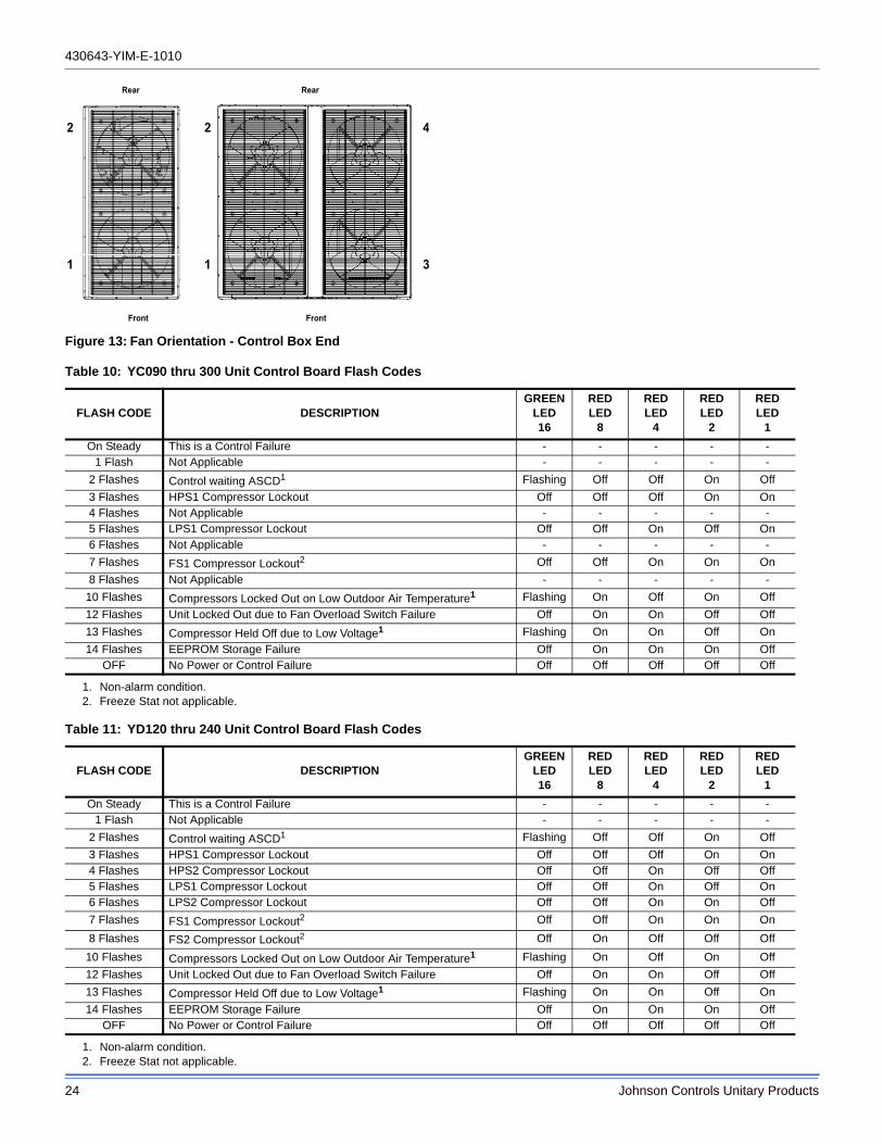
Figure 13: Fan Orientation - Control Box End
Rear
Front
Rear
Front
2
1
2
1
4
3
Table 10: YC090 thru 300 Unit Control Board Flash Codes
FLASH CODE DESCRIPTIONGREEN
LED16
REDLED
8
REDLED
4
REDLED
2
REDLED
1
On Steady This is a Control Failure - - - - -1 Flash Not Applicable - - - - -
2 Flashes Control waiting ASCD1
1. Non-alarm condition.
Flashing Off Off On Off
3 Flashes HPS1 Compressor Lockout Off Off Off On On4 Flashes Not Applicable - - - - -5 Flashes LPS1 Compressor Lockout Off Off On Off On6 Flashes Not Applicable - - - - -
7 Flashes FS1 Compressor Lockout2
2. Freeze Stat not applicable.
Off Off On On On
8 Flashes Not Applicable - - - - -
10 Flashes Compressors Locked Out on Low Outdoor Air Temperature1 Flashing On Off On Off
12 Flashes Unit Locked Out due to Fan Overload Switch Failure Off On On Off Off
13 Flashes Compressor Held Off due to Low Voltage1 Flashing On On Off On
14 Flashes EEPROM Storage Failure Off On On On OffOFF No Power or Control Failure Off Off Off Off Off
Table 11: YD120 thru 240 Unit Control Board Flash Codes
FLASH CODE DESCRIPTIONGREEN
LED16
REDLED
8
REDLED
4
REDLED
2
REDLED
1
On Steady This is a Control Failure - - - - -1 Flash Not Applicable - - - - -
2 Flashes Control waiting ASCD1
1. Non-alarm condition.
Flashing Off Off On Off
3 Flashes HPS1 Compressor Lockout Off Off Off On On4 Flashes HPS2 Compressor Lockout Off Off On Off Off5 Flashes LPS1 Compressor Lockout Off Off On Off On6 Flashes LPS2 Compressor Lockout Off Off On On Off
7 Flashes FS1 Compressor Lockout2
2. Freeze Stat not applicable.
Off Off On On On
8 Flashes FS2 Compressor Lockout2 Off On Off Off Off
10 Flashes Compressors Locked Out on Low Outdoor Air Temperature1 Flashing On Off On Off
12 Flashes Unit Locked Out due to Fan Overload Switch Failure Off On On Off Off
13 Flashes Compressor Held Off due to Low Voltage1 Flashing On On Off On
14 Flashes EEPROM Storage Failure Off On On On OffOFF No Power or Control Failure Off Off Off Off Off
430643-YIM-E-1010
Johnson Controls Unitary Products 25
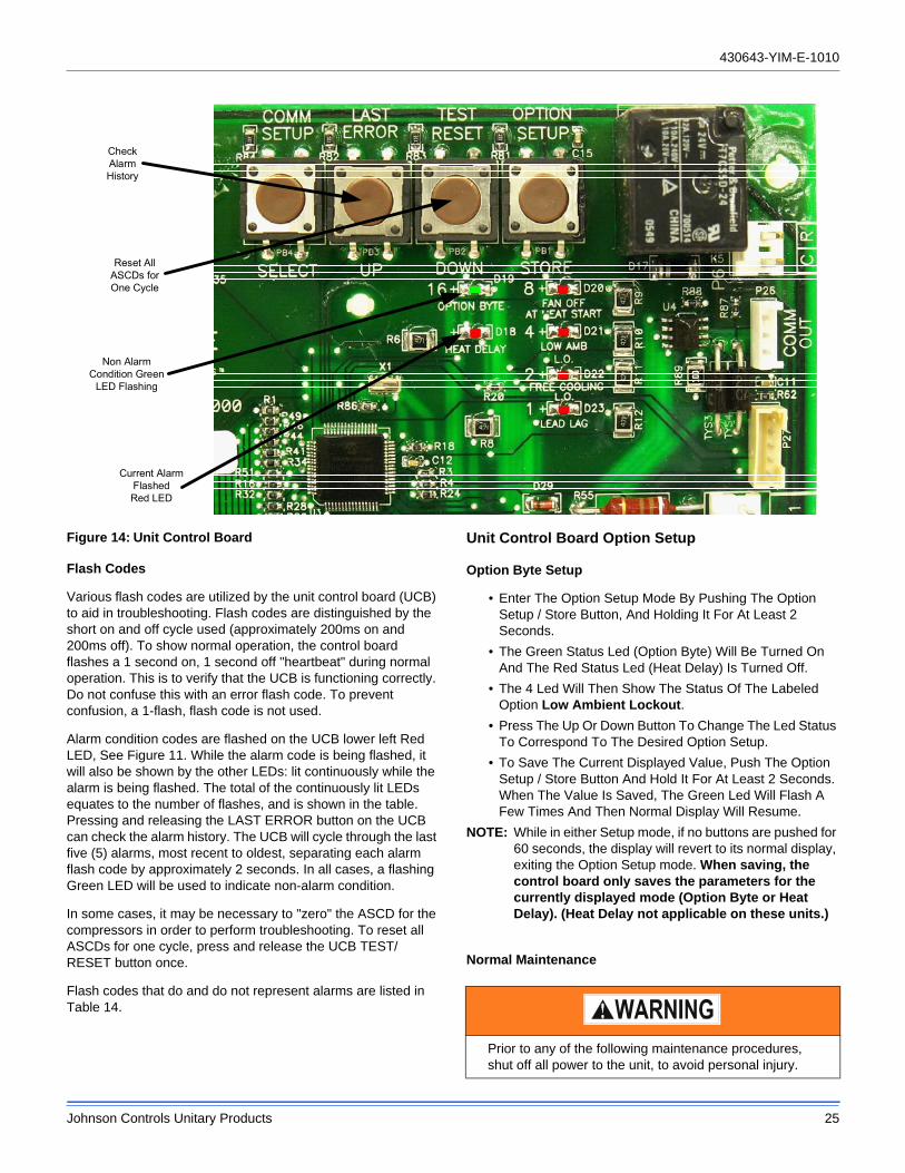
Figure 14: Unit Control Board
Flash Codes
Various flash codes are utilized by the unit control board (UCB) to aid in troubleshooting. Flash codes are distinguished by the short on and off cycle used (approximately 200ms on and 200ms off). To show normal operation, the control board flashes a 1 second on, 1 second off "heartbeat" during normal operation. This is to verify that the UCB is functioning correctly. Do not confuse this with an error flash code. To prevent confusion, a 1-flash, flash code is not used.
Alarm condition codes are flashed on the UCB lower left Red LED, See Figure 11. While the alarm code is being flashed, it will also be shown by the other LEDs: lit continuously while the alarm is being flashed. The total of the continuously lit LEDs equates to the number of flashes, and is shown in the table. Pressing and releasing the LAST ERROR button on the UCB can check the alarm history. The UCB will cycle through the last five (5) alarms, most recent to oldest, separating each alarm flash code by approximately 2 seconds. In all cases, a flashing Green LED will be used to indicate non-alarm condition.
In some cases, it may be necessary to "zero" the ASCD for the compressors in order to perform troubleshooting. To reset all ASCDs for one cycle, press and release the UCB TEST/ RESET button once.
Flash codes that do and do not represent alarms are listed in Table 14.
Unit Control Board Option Setup
Option Byte Setup
• Enter The Option Setup Mode By Pushing The Option Setup / Store Button, And Holding It For At Least 2 Seconds.
• The Green Status Led (Option Byte) Will Be Turned On And The Red Status Led (Heat Delay) Is Turned Off.
• The 4 Led Will Then Show The Status Of The Labeled Option Low Ambient Lockout.
• Press The Up Or Down Button To Change The Led Status To Correspond To The Desired Option Setup.
• To Save The Current Displayed Value, Push The Option Setup / Store Button And Hold It For At Least 2 Seconds. When The Value Is Saved, The Green Led Will Flash A Few Times And Then Normal Display Will Resume.
NOTE: While in either Setup mode, if no buttons are pushed for 60 seconds, the display will revert to its normal display, exiting the Option Setup mode. When saving, the control board only saves the parameters for the currently displayed mode (Option Byte or Heat Delay). (Heat Delay not applicable on these units.)
Normal Maintenance
CheckAlarmHistory
Reset AllASCDs forOne Cycle
Non AlarmCondition Green
LED Flashing
Current AlarmFlashedRed LED
Prior to any of the following maintenance procedures, shut off all power to the unit, to avoid personal injury.
430643-YIM-E-1010
26 Johnson Controls Unitary Products
Periodic maintenance consists of changing or cleaning filters and general cleaning of the outdoor coil.
FILTERS - Inspect once a month. Replace Disposable or clean Permanent Type as necessary. DO NOT replace Permanent Type with Disposable.
MOTORS - Outdoor fan motors are permanently lubricated and require no maintenance.
OUTDOOR COIL - Dirt should not be allowed to accumulate on the outdoor coil surface or other parts in the air circuit. Cleaning should be as often as necessary to keep the coil clean. Use a brush, vacuum cleaner attachment, or other suitable means. Be sure that the power to the unit is shut off prior to cleaning.
Troubleshooting
Cooling Troubleshooting Guide
On calls for cooling, if the compressors are operating but the supply air blower motor does not energize after a short delay (the room thermostat fan switch is in the “AUTO” position):
1. Turn the thermostat fan switch to the ON position. If the supply air blower motor does not energize, go to Step 3.
2. If the blower motor runs with the fan switch in the ON position but will not run after the first compressor has energized when the fan switch is in the AUTO position, check the room thermostat for contact between R and G in the AUTO position during calls for cooling.
3. If the supply air blower motor does not energize when the fan switch is set to ON, check that line voltage is being supplied to the contacts of the M3, contactor, and that the contactor is pulled in. Check for loose wiring between the contactor and the supply air blower motor.
4. If M3 is pulled in and voltage is supplied to M3, lightly touch the supply air blower motor housing. If it is hot, the motor may be off on internal protection. Cancel any thermostat calls and set the fan switch to AUTO. Wait for the internal overload to reset. Test again when cool.
5. If M3 is not pulled in, check for 24 volts at the M3 coil. If 24 volts are present at M3 but M3 is not pulled in, replace the contactor.
6. Failing the above, if there is line voltage supplied at M3, M3 is pulled in, and the supply air blower motor still does not operate, replace the motor.
7. If 24 volts is not present at M3, check that 24 volts is present at the UCB supply air blower motor terminal, “FAN”. If 24 volts is present at the FAN, check for loose wiring between the UCB and M3.
8. If 24 volts is not present at the “FAN” terminal, check for 24 volts from the room thermostat. If 24 volts are not present from the room thermostat, check for the following:
a. Proper operation of the room thermostat (contact between R and G with the fan switch in the ON position and in the AUTO position during operation calls).
b. Proper wiring between the room thermostat and the UCB, and
c. Loose wiring from the room thermostat to the UCB
9. If 24 volts is present at the room thermostat but not at the UCB, check for proper wiring between the thermostat and the UCB, i.e. that the thermostat G terminal is connected to the G terminal of the UCB, and for loose wiring.
10. If the thermostat and UCB are properly wired, replace the UCB.
On calls for cooling, the supply air blower motor is operating but compressor #1 is not (the room thermostat fan switch is in the “AUTO” position):
1. If compressor #1 does not energize on a call for cooling, check for line voltage at the compressor contactor, M1, and that the contactor is pulled in. Check for loose wiring between the contactor and the compressor.
2. If M1 is pulled in and voltage is supplied at M1, lightly touch the compressor housing. If it is hot, the compressor may be off on inherent protection. Cancel any calls for cooling and wait for the internal overload to reset. Test again when cool.
Only soap and water can be used to clean microchannel coils. Do not use an acid cleaner.
Exercise care when cleaning the coil so that the coil fins are not damaged.
Do not permit the hot condenser air discharge to be obstructed by overhanging structures or shrubs.
Troubleshooting of components necessarily requires opening the electrical control box with the power connected to the unit. Use extreme care when working with live circuit! Check the unit nameplate for the correct range before making any connections with line terminals.
The wire number or color and terminal designations referred to may vary. Check the wiring label inside the control box access panel for the correct wiring.
430643-YIM-E-1010
Johnson Controls Unitary Products 27
3. If M1 is not pulled in, check for 24 volts at the M1 coil. If 24 volts are present and M1 is not pulled in, replace the contactor.
4. Failing the above, if voltage is supplied at M1, M1 is pulled in, and the compressor still does not operate, replace the compressor.
5. If 24 volts is not present at M1, check for 24 volts at the UCB terminal, C1. If 24 volts is present, check for loose wiring between C1 and the compressor contactor.
6. If 24 volts is not present at the C1 terminal, check for 24 volts from the room thermostat at the UCB Y1 terminal. If 24 volts is not present from the room thermostat, check for the following:
a. 24 volts at the thermostat Y1 terminal
b. Proper wiring between the room thermostat and the UCB, i.e. Y1 to Y1, Y2 to Y2, and
c. Loose wiring from the room thermostat to the UCB
7. If 24 volts is present at the UCB Y1 terminal, the compressor may be out due to an open high-pressure switch, low-pressure switch, or freezestat. Check for 24 volts at the HPS1, LPS1, and FS1 terminals of the UCB. If a switch has opened, there should be a voltage potential between the UCB terminals, e.g. if LPS1 has opened, there will be a 24-volt potential between the LPS1 terminals.
8. If 24 volts is present at the UCB Y1 terminal and none of the protection switches have opened, the UCB may have locked out the compressor for repeat trips. The UCB should be flashing an alarm code. If not, press and release the ALARMS button on the UCB. The UCB will flash the last five alarms on the LED. If the compressor is locked out, cancel any call for cooling. This will reset any compressor lock outs.
NOTE: While the above step will reset any lockouts, compressor #1 may be held off for the ASCD. See the next step.
9. If 24 volts is present at the UCB Y1 terminal and none of the switches are open and the compressor is not locked out, the UCB may have the compressor in an ASCD. Check the LED for an indication of an ASCD cycle. The ASCD should time out within 5 minutes. Press and release the TEST button to reset all ASCDs.
10. If 24 volts is present at the UCB Y1 terminal and the compressor is not out due to a protective switch trip, repeat trip lock out, or ASCD, the economizer terminals of the UCB may be improperly wired. Check for 24 volts at the Y1 “OUT” terminal of the UCB. If 24 volts is present, trace the wiring from Y1 “OUT” for incorrect wiring. If 24 volts is not present at the Y1 “OUT” terminal, the UCB must be replaced.
11. If 24 volts is present at the Y1 OUT terminal, check for 24 volts at the Y1 “ECON” terminal. If 24 volts is not present, check for loose wiring from the Y1 “OUT” terminal to the Mate-N-Lock plug, the jumper in the Mate-N-Lock plug, and in the wiring from the Mate-N-Lock plug to the Y1 “ECON” terminal.
12. If none of the above corrected the error, test the integrity of the UCB. Disconnect the C1 terminal wire and jumper it to the Y1 terminal. DO NOT jump the Y1 to C1 terminals. If the compressor engages, the UCB has faulted.
13. If none of the above correct the error, replace the UCB.
On a call for the second stage of cooling, the supply air blower motor and compressor #1 are operating but compressor #2 is not (the room thermostat fan switch is in the “AUTO” position):
1. Compressor #2 will not energize simultaneously with compressor #1 if a call for both stages of cooling is received. The UCB delays compressor #2 by 30 seconds to prevent a power surge. If after the delay compressor #2 does not energize on a second stage call for cooling, check for line voltage at the compressor contactor, M2, and that the contactor is pulled in. Check for loose wiring between the contactor and the compressor.
2. If M2 is pulled in and voltage is supplied at M2, lightly touch the compressor housing. If it is hot, the compressor may be off on inherent protection. Cancel any calls for cooling and wait for the internal overload to reset. Test again when cool.
3. If M2 is not pulled in, check for 24 volts at the M2 coil. If 24 volts is present and M2 is not pulled in, replace the contactor.
4. Failing the above, if voltage is supplied at M2, M2 is pulled in, and the compressor still does not operate, replace the compressor.
5. If 24 volts is not present at M2, check for 24 volts at the UCB terminal, C2. If 24 volts are present, check for loose wiring between C2 and the compressor contactor.
6. If 24 volts is not present at the C2 terminal, check for 24 volts from the room thermostat at the UCB Y2 terminal. If 24 volts is not present from the room thermostat, check for the following:
a. 24 volts at the thermostat Y2 terminal
b. Proper wiring between the room thermostat and the UCB, i.e. Y1 to Y1, Y2 to Y2, and
c. Loose wiring from the room thermostat to the UCB
7. If 24 volts is present at the UCB Y2 terminal, the compressor may be out due to an open high-pressure switch, low-pressure switch, or freezestat. Check for 24 volts at the HPS2, LPS2, and FS2 terminals of the UCB. If a switch has opened, there should be a voltage potential between the UCB terminals, e.g. if LPS2 has opened, there will be 24 volts of potential between the LPS2 terminals.
8. If 24 volts is present at the UCB Y2 terminal and none of the protection switches have opened, the UCB may have locked out the compressor for repeat trips. The UCB should be flashing a code. If not, press and release the ALARMS button on the UCB. The UCB will flash the last five alarms on the LED. If the compressor is locked out, remove any call for cooling at the thermostat or by disconnecting the thermostat wiring at the Y2 UCB terminal. This will reset any compressor lock outs.
430643-YIM-E-1010
28 Johnson Controls Unitary Products
NOTE: While the above step will reset any lock outs, compressor #1 will be held off for the ASCD, and compressor #2 may be held off for a portion of the ASCD. See the next step.
9. If 24 volts is present at the UCB Y2 terminal and none of the switches are open and the compressor is not locked out, the UCB may have the compressor in an ASCD. Check the LED for an indication of an ASCD cycle. The ASCD should time out within 5 minutes. Press and release the TEST button to reset all ASCDs.
10. If none of the above corrected the error, test the integrity of the UCB. Disconnect the C2 terminal wire and jumper it to the Y2 terminal. DO NOT jump the Y2 to C2 terminals. If the compressor engages, the UCB has faulted.
11. If none of the above correct the error, replace the UCB.
On a call for cooling, the supply air blower motor and compressor #2 are operating but compressor #1 is not (the room thermostat fan switch is in the “AUTO” position):
1. Compressor #2 is energized in place of compressor #1 when compressor #1 is unavailable for cooling calls. Check the UCB for alarms indicating that compressor #1 is locked out. Press and release the ALARMS button if the LED is not flashing an alarm.
2. Check for line voltage at the compressor contactor, M1, and that the contactor is pulled in. Check for loose wiring between the contactor and the compressor.
3. If M1 is pulled in and voltage is supplied at M1, lightly touch the compressor housing. If it is hot, the compressor may be off on inherent protection. Cancel any calls for cooling and wait for the internal overload to reset. Test again when cool.
4. If M1 is not pulled in, check for 24 volts at the M1 coil. If 24 volts is present and M1 is not pulled in, replace the contactor.
5. Failing the above, if voltage is supplied at M1, M1 is pulled in, and the compressor still does not operate, replace the compressor.
6. If 24 volts is not present at M1, check for 24 volts at the UCB terminal, C1. If 24 volts is present, check for loose wiring between C1 and the compressor contactor.
7. If 24 volts is not present at the C1 terminal, check for 24 volts from the room thermostat at the UCB Y1 terminal. If 24 volts are not present at the UCB Y1 terminal, the UCB may have faulted. Check for 24 volts at the Y1 ECON terminal. If 24 volts is not present at Y1 “ECON”, the UCB
has faulted. The UCB should de-energize all compressors on a loss of call for the first stage of cooling, i.e. a loss if 24 volts at the Y1 terminal.
8. If 24 volts are present at the UCB Y1 terminal, the compressor may be out due to an open high-pressure switch, low-pressure switch, or freezestat. Check for 24 volts at the HPS1, LPS1, and FS1 terminals of the UCB. If a switch has opened, there should be a voltage potential between the UCB terminals, e.g. if LPS1 has opened, there will be a 24-volt potential between the LPS1 terminals.
9. If 24 volts is present at the UCB Y1 terminal and none of the protection switches have opened, the UCB may have locked out the compressor for repeat trips. The UCB should be flashing a code. If not, press and release the ALARMS button on the UCB. The UCB will flash the last five alarms on the LED. If the compressor is locked out, remove any call for cooling. This will reset any compressor lock outs.
NOTE: While the above step will reset any lock outs, compressor #2 will be held off for the ASCD, and compressor #1 may be held off for a portion of the ASCD. See the next step.
10. If 24 volts is present at the UCB Y1 terminal and none of the switches are open and the compressor is not locked out, the UCB may have the compressor in an ASCD. Check the LED for an indication of an ASCD cycle. The ASCD should time out within 5 minutes. Press and release the TEST button to reset all ASCDs.
11. If 24 volts is present at the UCB Y1 terminal and the compressor is not out due to a protective switch trip, repeat trip lock out, or ASCD, the economizer terminals of the UCB may be improperly wired. Check for 24 volts at the Y1 “OUT” terminal of the UCB. If 24 volts is present, trace the wiring from Y1 “OUT” for incorrect wiring. If 24 volts is not present at the Y1 “OUT” terminal, the UCB must be replaced.
12. If 24 volts is present at the Y1 “OUT” terminal, check for 24 volts at the Y1 “ECON” terminal. If 24 volts is not present, check for loose wiring from the Y1 “OUT” terminal to the Mate-N-Lock plug, the jumper in the Mate-N-Lock plug, and in the wiring from the Mate-N-Lock plug to the Y1 “ECON” terminal.
13. If none of the above corrected the error, test the integrity of the UCB. Disconnect the C1 terminal wire and jumper it to the Y1 terminal. DO NOT jump the Y1 to C1 terminals. If the compressor engages, the UCB has faulted.
If none of the above correct the error, replace the UCB.
430643-YIM-E-1010
Johnson Controls Unitary Products 29
Figure 15: YC090 Charging Chart
Figure 16: YC120 Charging Chart
Charging CurvesYC090
200
300
400
500
600
120 130 140 150 160 170 180
Suction Pressure (psi)
Dis
char
ge P
ress
ure
(psi
) 115°
105°
95°
85°
75°
65°
Out
door
Air
Ente
ring
Con
dens
er (F
)
1. Make sure that both condenser fans are running when charging.2. This chart is applicable to unit with the TXV’s left to the factory setting. If the TXV’s have been adjusted in the field, the charging chart may no longer apply.
Charging CurvesYC120
200
300
400
500
600
120 130 140 150 160 170 180
Suction Pressure (psi)
Dis
char
ge P
ress
ure
(psi
)
115°
105°
95°
85°
65°
75°
Out
door
Air
Ente
ring
Con
dens
er (F
)
1. Make sure that both condenser fans are running when charging.2. This chart is applicable to unit with the TXV’s left to the factory setting. If the TXV’s have been adjusted in the field, the charging chart may no longer apply.
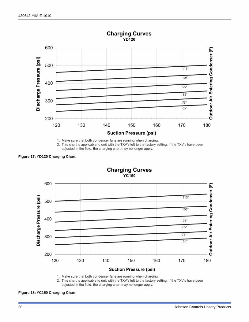
430643-YIM-E-1010
30 Johnson Controls Unitary Products
Figure 17: YD120 Charging Chart
Figure 18: YC150 Charging Chart
Charging CurvesYD120
200
300
400
500
600
120 130 140 150 160 170 180
Suction Pressure (psi)
Dis
char
ge P
ress
ure
(psi
)
115°
105°
95°
85°
75°
65°
Out
door
Air
Ente
ring
Con
dens
er (F
)
1. Make sure that both condenser fans are running when charging.2. This chart is applicable to unit with the TXV’s left to the factory setting. If the TXV’s have been adjusted in the field, the charging chart may no longer apply.
Charging CurvesYC150
200
300
400
500
600
120 130 140 150 160 170 180
Suction Pressure (psi)
Dis
char
ge P
ress
ure
(psi
)
115°
105°
95°
85°
75°
65°
Out
door
Air
Ente
ring
Con
dens
er (F
)
1. Make sure that both condenser fans are running when charging.2. This chart is applicable to unit with the TXV’s left to the factory setting. If the TXV’s have been adjusted in the field, the charging chart may no longer apply.
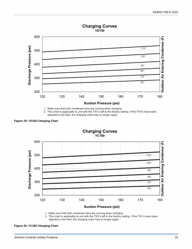
430643-YIM-E-1010
Johnson Controls Unitary Products 31
Figure 19: YD150 Charging Chart
Figure 20: YC180 Charging Chart
Charging CurvesYD150
200
300
400
500
600
120 130 140 150 160 170 180
Suction Pressure (psi)
Dis
char
ge P
ress
ure
(psi
)
115°
105°
95°
85°
75°
65°
Out
door
Air
Ente
ring
Con
dens
er (F
)
1. Make sure that both condenser fans are running when charging.2. This chart is applicable to unit with the TXV’s left to the factory setting. If the TXV’s have been adjusted in the field, the charging chart may no longer apply.
Charging CurvesYC180
200
300
400
500
600
120 130 140 150 160 170 180
Suction Pressure (psi)
Dis
char
ge P
ress
ure
(psi
)
1. Make sure that both condenser fans are running when charging.2. This chart is applicable to unit with the TXV’s left to the factory setting. If the TXV’s have been adjusted in the field, the charging chart may no longer apply.
Out
door
Air
Ente
ring
Con
dens
er (F
)
115°
95°
65°
75°
85°
105°
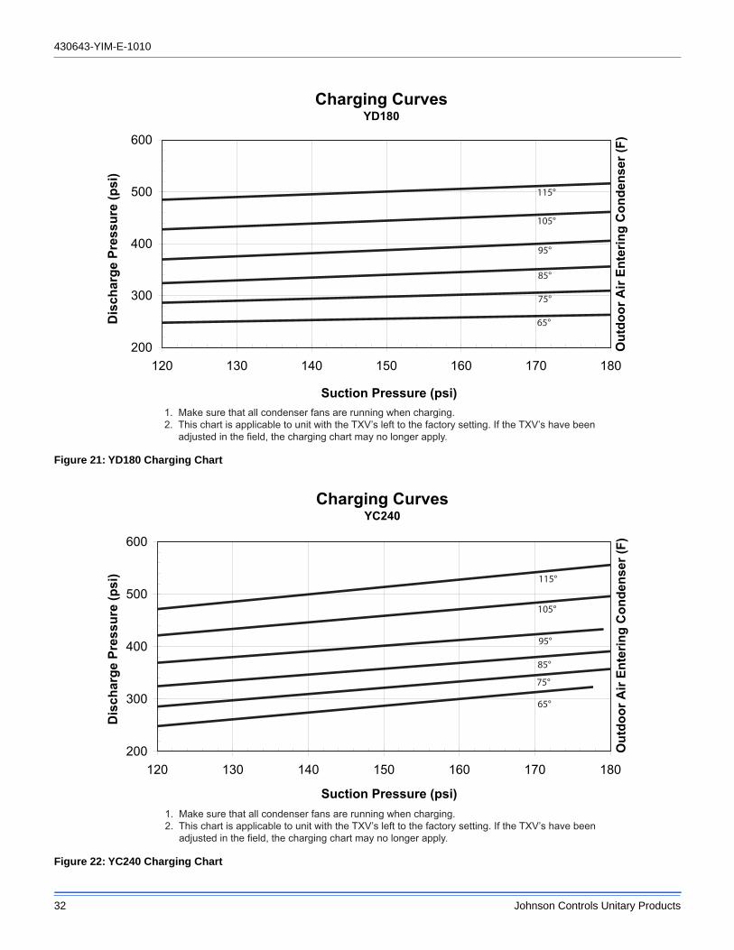
430643-YIM-E-1010
32 Johnson Controls Unitary Products
Figure 21: YD180 Charging Chart
Figure 22: YC240 Charging Chart
Charging CurvesYD180
200
300
400
500
600
120 130 140 150 160 170 180
Suction Pressure (psi)
Dis
char
ge P
ress
ure
(psi
)
115°
105°
95°
85°
75°
65°
Out
door
Air
Ente
ring
Con
dens
er (F
)
1. Make sure that all condenser fans are running when charging.2. This chart is applicable to unit with the TXV’s left to the factory setting. If the TXV’s have been adjusted in the field, the charging chart may no longer apply.
Charging CurvesYC240
200
300
400
500
600
120 130 140 150 160 170 180
Suction Pressure (psi)
Dis
char
ge P
ress
ure
(psi
) 115°
105°
95°
85°
75°
65°
Out
door
Air
Ente
ring
Con
dens
er (F
)
1. Make sure that all condenser fans are running when charging.2. This chart is applicable to unit with the TXV’s left to the factory setting. If the TXV’s have been adjusted in the field, the charging chart may no longer apply.
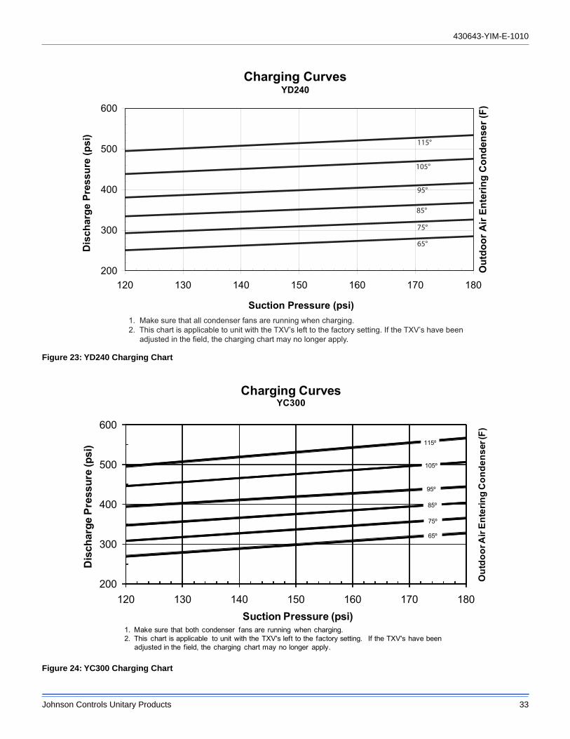
430643-YIM-E-1010
Johnson Controls Unitary Products 33
Figure 23: YD240 Charging Chart
Figure 24: YC300 Charging Chart
Charging CurvesYD240
200
300
400
500
600
120 130 140 150 160 170 180
Suction Pressure (psi)
Dis
char
ge P
ress
ure
(psi
)
115°
105°
95°
85°
75°
65°
Out
door
Air
Ente
ring
Con
dens
er (F
)
1. Make sure that all condenser fans are running when charging.2. This chart is applicable to unit with the TXV’s left to the factory setting. If the TXV’s have been adjusted in the field, the charging chart may no longer apply.
200
300
400
500
600
120 130 140 150 160 170 180
Dis
char
ge P
ress
ure
(psi
)
Suction Pressure (psi)
Charging CurvesYC300
115º
105º
95º
85º
75º
65º
1. Make sure that both condenser fans are running when charging.2. This chart is applicable to unit with the TXV's left to the factory setting. If the TXV's have been
adjusted in the field, the charging chart may no longer apply.
Out
door
Air
Ente
ring
Con
dens
er (F
)
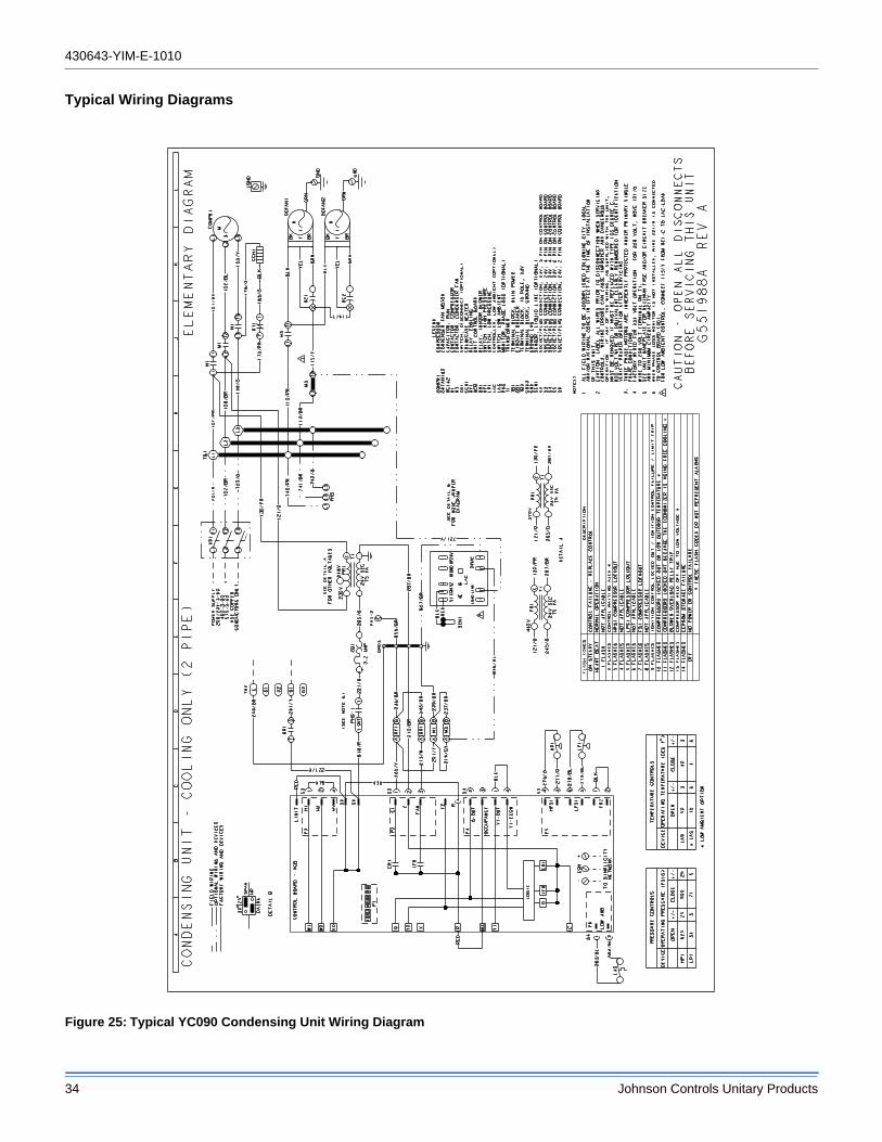
430643-YIM-E-1010
34 Johnson Controls Unitary Products
Typical Wiring Diagrams
Figure 25: Typical YC090 Condensing Unit Wiring Diagram
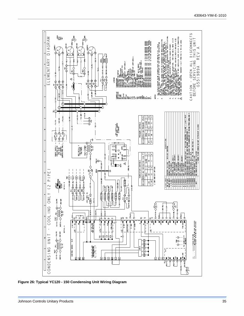
430643-YIM-E-1010
Johnson Controls Unitary Products 35
Figure 26: Typical YC120 - 150 Condensing Unit Wiring Diagram
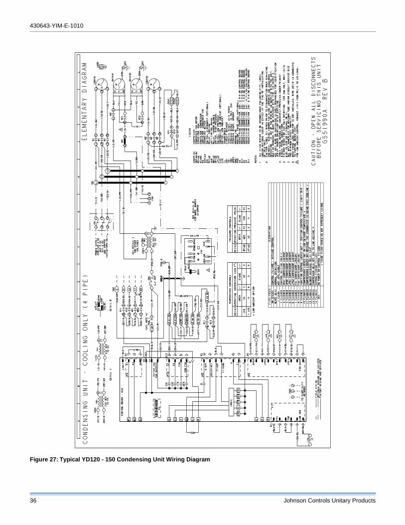
430643-YIM-E-1010
36 Johnson Controls Unitary Products
Figure 27: Typical YD120 - 150 Condensing Unit Wiring Diagram
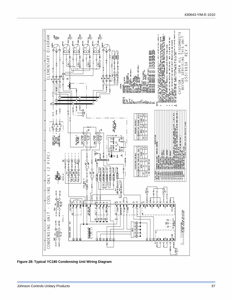
430643-YIM-E-1010
Johnson Controls Unitary Products 37
Figure 28: Typical YC180 Condensing Unit Wiring Diagram
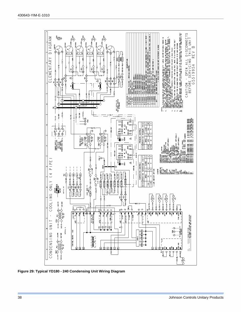
430643-YIM-E-1010
38 Johnson Controls Unitary Products
Figure 29: Typical YD180 - 240 Condensing Unit Wiring Diagram
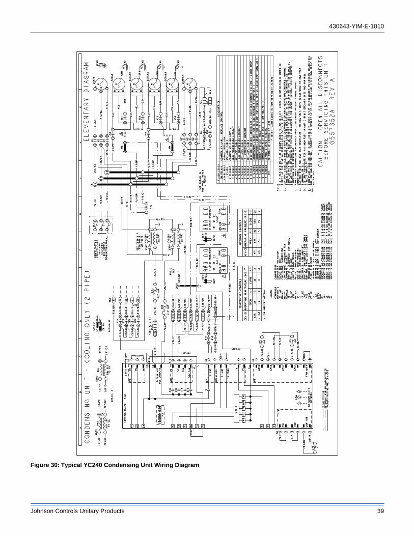
430643-YIM-E-1010
Johnson Controls Unitary Products 39
Figure 30: Typical YC240 Condensing Unit Wiring Diagram
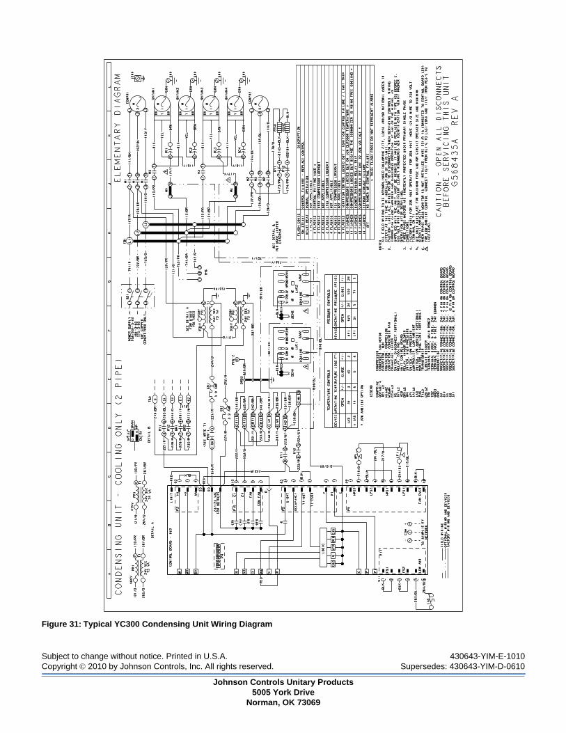
Subject to change without notice. Printed in U.S.A. 430643-YIM-E-1010Copyright © 2010 by Johnson Controls, Inc. All rights reserved. Supersedes: 430643-YIM-D-0610
Johnson Controls Unitary Products5005 York Drive
Norman, OK 73069
Figure 31: Typical YC300 Condensing Unit Wiring Diagram