qwest guidelines
TRANSCRIPT

Qwest Corporation Technical Publication
Telecommunications
Equipment Installation Guidelines
Copyright 1993, 1996, 1997, 1998, 1999, 2000, 2001, 2003, 2007 ©
77350
Qwest Corporation Issue N All Rights Reserved January 2007

QWEST Tech Pub 77350 Notice Issue N, January 2007
Throughout this publication, the term Qwest signifies Qwest Corporation.
NOTICE
This document describes Qwest’s requirements for Suppliers of Central Office Equipment Installation Services. The information provided in this document includes workmanship guidelines, technical requirements, and Supplier competency requirements.
Qwest Corporation reserves the right to revise this document for any reason, including but not limited to, conformity with standards promulgated by various governmental or regulatory agencies; utilization of advances in the state of the technical arts; or to reflect changes in the design of equipment, techniques, or procedures described or referred to herein.
Liability to anyone arising out of use or reliance upon any information set forth herein is expressly disclaimed, and no representation or warranties, expressed or implied, are made with respect to the accuracy or utility of any information set forth herein.
This document is not to be construed as a suggestion to any manufacturer to modify or change any of its products, nor does this publication represent any commitment by Qwest Corporation to purchase any specific products. Further, conformance to this publication does not constitute a guarantee of a given supplier's equipment and/or its associated documentation.
Future issues of Technical Publication 77350 will be announced to the industry at least 30 days prior to the issuance date. This notice, which will come through our standard customer notification channels, will allow the customer time to comment on the proposed revisions.
Ordering information for Qwest Publications can be obtained from the Reference Section of this document.
If further information is required, please contact:
Qwest Corporation
Manager – New Services Planning 700 W. Mineral Ave. Littleton, CO 80120 (303) 707-9497 Fax #
E-mail: [email protected]


QWEST Tech Pub 77350 Comments Issue N, January 2007
COMMENTS on PUB 77350
PLEASE SEND YOUR COMMENTS/SUGGESTIONS TO:
Qwest Corporation Manager – New Services Planning
700 W. Mineral Ave. Littleton, CO 80120 (303) 707-9497 Fax #
E-mail: [email protected]
Information from you helps us to improve our Publications. Please take a few moments to answer the following questions and return to the above address.
Was this Publication valuable to you in understanding The technical parameters of our service? YES ______ NO ______
Was the information accurate and up-to-date? YES ______ NO ______
Was the information easily understood? YES ______ NO ______
Were the contents logically sequenced? YES ______ NO ______
Were the tables and figures understandable and helpful YES ______ NO ______
Were the pages legible? YES ______ NO ______
If you answered NO to any of the questions and/or if you have any other comments or suggestions, please explain:
__________________________________________________________________________
__________________________________________________________________________
__________________________________________________________________________ (Attach additional sheet, if necessary)
Name __________________________________________ Date ______________________
Company __________________________________________________________________
Address ___________________________________________________________________
Telephone Number __________________________________________________________________________
E-Mail ____________________________________________________________________

QWEST Tech Pub 77350 Table of Contents Issue N, January 2007
TOC-i
CONTENTS
Chapter and Section Page 1. Introduction ................................................................................................................ 1-1
1.1 General (Scope of Document) ....................................................................... 1-1 1.2 Qwest Quality Audits..................................................................................... 1-1 1.3 Quality Policy Statement ............................................................................... 1-1 1.4 Reason For Reissue ......................................................................................... 1-1 1.5 Document Organization................................................................................. 1-2
2. General Requirements .............................................................................................. 2-1 2.1 General.............................................................................................................. 2-1 2.2 Facility Access and Security .......................................................................... 2-3 2.3 Facility Environmental Conditions, Upkeep, Storage, and Handling.................................................................................................. 2-6 2.4 Environmental, Safety, and Health .............................................................. 2-8 2.5 Electrostatic Discharge ................................................................................... 2-16 2.6 Fire Protection Policy...................................................................................... 2-16 2.7 Network Alarms.............................................................................................. 2-19 2.8 Equipment Performance Tests ...................................................................... 2-22 2.9 Maintenance Window .................................................................................... 2-22 2.10 Wood Products and Wood for Use in Equipment Locations ................... 2-23
2.11 Letter of Deviation .......................................................................................... 2-23
3. Assembly and Ironwork ........................................................................................... .3-1 3.1 General Requirements.................................................................................... 3-1 3.2 Apparatus......................................................................................................... 3-2 3.3 Appliance/Base and Utility Outlets and Permanently Mounted
Power Strips..................................................................................................... 3-2 3.4 Auxiliary Framing........................................................................................... 3-2 3.5 Bolts, Nuts, Screws, and Threaded Rods..................................................... 3-3 3.6 Cable Racks ...................................................................................................... 3-4 3.7 AC Conduit ..................................................................................................... 3-6 3.8 Cotter Pins........................................................................................................ 3-6 3.9 Earthquake Considerations ........................................................................... 3-6 3.10 Equipment Removal For Reuse or Retirement ........................................... 3-7 3.11 Fiber Optic Protective/Distribution Systems ............................................. 3-8 3.12 Frames, Bays, Cabinets, and Stands ............................................................. 3-10 3.13 Framework and Ironwork Components...................................................... 3-14 3.14 Lighting Fixtures ............................................................................................. 3-15

Table of Contents QWEST Tech Pub 77350 Issue N, January 2007
TOC-ii
4.3.7
CONTENTS (Continued)
Chapter and Section Page 3.15 Rolling Ladders and Tracks........................................................................... 3-15 3.16 Units of Equipment......................................................................................... 3-16 3.17 Antenna and associated Transmission Lines.............................................. 3-20 3.18 Earthquake Zone Map.................................................................................... 3-21 3.19 Alignment Tables ............................................................................................ 3-22 3.20 Building Envelope Drilling Procedures....................................................... 3-22 3.21 Floor Anchors and Installation Instructions ............................................... 3-23 3.22 Floor Anchor Bolt Modification Procedures: .............................................. 3-25 3.23 Floor Tile Punch Procedure: .......................................................................... 3-25 3.24 Floor Tile Drilling With HEPA Vacuum Attachment................................ 3-26 3.25 Floor Tile Drilling With Separate HEPA Vacuum That Is Not
Attached To Tile Drill: .................................................................................... 3-27 3.26 Raised Floors.................................................................................................... 3-27 3.27 Waterproof Floor............................................................................................. 3-28 3.28 Battery Containment....................................................................................... 3-28
4. Cable Holes, Penetrations, and Fire/Smoke Protection...................................... 4-1 4.1 General Requirements.................................................................................... 4-1 4.2 Closure Labels ................................................................................................. 4-2 4.3 Horizontal, Miscellaneous, and Vertical Penetrations .............................. 4-3 4.3.6 Intumescent Firestopping – Floor Penetrations.............................. 4-4
Intumescent Firestopping – Through Wall Penetrations ............. 4-5 4.4 Firestopped Penetration (Cable Hole) Designations ................................. 4-6 4.5 Approved Materials........................................................................................ 4-6 4.6 Approved Label Template............................................................................. 4-6 4.7 Application Exhibits ....................................................................................... 4-7 4.8 Embargoing Blocked/Exhausted Cable Hole Penetrations...................... 4-12
5. Cabling, Forming, Running, and Securing ........................................................... 5-1 5.1 General Requirements.................................................................................... 5-1 5.2 Cable Mining ................................................................................................... 5-2 5.3 Bending and Forming..................................................................................... 5-3 5.4 Protection and Storage ................................................................................... 5-4 5.5 Securing and Supporting ............................................................................... 5-5 5.6 Power cables .................................................................................................... 5-6 5.7 Grounding Conductors .................................................................................. 5-7

QWEST Tech Pub 77350 Table of Contents Issue N, January 2007
TOC-iii
CONTENTS (Continued)
Chapter and Section Page 5.8 Cable Pile-up.................................................................................................... 5-8 5.9 Coaxial Cables ................................................................................................. 5-9 5.10 Fiber Optic Cable ............................................................................................ 5-9 5.11 Ribbon Cable.................................................................................................... 5-14 5.12 Repair of Damaged Cables ............................................................................ 5-14 5.13 Spliced Cables, Splicing Systems, and Mated Connectable Cables ......... 5-14 5.14 Use of Nylon and Plastic Cable Ties ............................................................ 5-15 5.15 Securing Tables................................................................................................ 5-16 5.16 Securing Figures.............................................................................................. 5-18
6. Wiring........................................................................................................................... 6-1 6.1 General Requirements.................................................................................... 6-1 6.2 Fanned and Unsewed Forms......................................................................... 6-1 6.3 Sewed Forms.................................................................................................... 6-1 6.4 Protection ......................................................................................................... 6-2 6.5 Cable Tags ........................................................................................................ 6-2
7. Connecting .................................................................................................................. 7-1 7.1 General Requirements.................................................................................... 7-1 7.2 Coaxial Connections and Test/Turn-up Parameters................................. 7-1 7.3 Connectable Cables......................................................................................... 7-3 7.4 Crimp Compression Connectors, Splices, and Taps.................................. 7-3 7.5 Quick Clip/Slotted Beam Connections ....................................................... 7-4 7.6 Soldered Connections..................................................................................... 7-5 7.7 Solderless Wire Wrapped Connections ....................................................... 7-5 7.8 Solderless Wire Wrapped Exhibits............................................................... 7-7 7.9 Fiber Optic Cable Connections ..................................................................... 7-11
8. Equipment Designations .......................................................................................... 8-1 8.1 General Requirements.................................................................................... 8-2 8.2 Color of Characters for Stamping and Labels............................................. 8-2 8.3 Designation Conventions............................................................................... 8-2 8.4 Connectors and Connectable Cables........................................................... 8-3 8.5 Distributing and Protector Frames............................................................... 8-4 8.6 Drawings and Assignment Records............................................................. 8-4 8.7 AC Circuits....................................................................................................... 8-4

Table of Contents QWEST Tech Pub 77350 Issue N, January 2007
TOC-iv
CONTENTS (Continued)
Chapter and Section Page 8.8 Batteries and Battery Stands.......................................................................... 8-5 8.9 DC Breakers, Fuses, Switches, and Shunts.................................................. 8-6 8.10 DC Distribution Elements.............................................................................. 8-7 8.11 Conductors, Leads, Bonding/Grounding Points ....................................... 8-8 8.12 Mechanical Equipment and Rooms.............................................................. 8-9 8.13 High Temperature Surfaces........................................................................... 8-9 8.14 High Voltage Surfaces .................................................................................... 8-9 8.15 Rectifiers, Converters, Inverters, Power Supplies...................................... 8-9 8.16 Bus bars and Ground Bars ............................................................................. 8-9 8.17 Rolling Ladders ............................................................................................... 8-10 8.18 Cable Rack Systems ........................................................................................ 8-10 8.19 Marking Records / Drawings ....................................................................... 8-11 8.20 Miscellaneous stenciling and Font Size Tables........................................... 8-11 8.21 Distributing Frame Exhibits .......................................................................... 8-14 8.22 Bay Equipment Labels................................................................................... 8-15 8.23 Temporary Removal and Installation Tag................................................... 8-16 8.24 Labels ................................................................................................................ 8-16 8.25 Collocation Decommission Cable Tag ......................................................... 8-20 8.26 Fire Code Power Room Door Placard.......................................................... 8-21 8.27 Alarm / OSS Testing Incompletion Tag ...................................................... 8-22 8.28 Lock out/Tag out Tag .................................................................................... 8-23 8.29 Equipment “Removal from Service” Tag .................................................... 8-24 8.30 Building Columns ........................................................................................... 8-24 8.31 Equipment “Hot Surface” Tag ...................................................................... 8-25 8.32 NFPA “Very Early Warning Fire Detection Alarm System”.................... 8-25
9. Power ............................................................................................................................ 9-1 9.1 AC Circuits ........................................................................................................ 9-1 9.2 Primary & Secondary Distribution ................................................................ 9-7 9.3 Battery Primary Conductors ........................................................................... 9-9 9.4 Bus Bars.............................................................................................................. 9-10 9.5 Cabinets.............................................................................................................. 9-11 9.6 Connecting......................................................................................................... 9-11 9.7 Fuse Bays, BDFBs, POWER BOARDs, etc..................................................... 9-14 9.8 Fuse Contact Preparation and Protection ..................................................... 9-15

QWEST Tech Pub 77350 Table of Contents Issue N, January 2007
TOC-v
9.9 Knife Switches, Fuses and Fuse Mountings ................................................. 9-15
CONTENTS (Continued)
Chapter and Section Page 9.10 Standby Engines ............................................................................................... 9-16
9.11 Wire Information Table ................................................................................... 9-19 10. Storage Batteries......................................................................................................... 10-1
10.1 Cautions ............................................................................................................. 10-1 10.2 General Requirements and Procedures......................................................... 10-1 10.3 Initial Battery Charge Procedures for Flooded Cells................................... 10-4 10.4 Flooded Lead Acid Type Battery Charging.................................................. 10-5 10.5 Initial Charge and Turnover Requirements for Flooded Cells .................. 10-6 10.6 Initial Charge Procedures for Valve Regulated Lead Acid Cells .............. 10-7 10.7 Charge Procedures for Valve Regulated Lead Acid Cells Stored for Reuse
Applications ...................................................................................................... 10-8 10.8 Electrolyte Spills ............................................................................................... 10-8 10.9 Installation/Removal Requirements for Lithium-based Batteries............ 10-8 10.10 Installation Requirements for Nickel-based Batteries................................. 10-9
11. Bonding and Grounding .......................................................................................... 11-1 11.1 General Requirements ..................................................................................... 11-1 11.2 Central Office and Facility Main Ground Systems...................................... 11-2 11.3 Grounding Frames, Bays and Cabinets......................................................... 11-3 11.4 Equipment Chassis Shield and Quiet Grounding
Connections ....................................................................................................... 11-3 11.5 Isolated Ground Systems for Stored Program Control
Systems............................................................................................................... 11-4 11.6 Circuit Pack Storage Cabinets......................................................................... 11-5 11.7 Foreign Object Grounding .............................................................................. 11-5 11.8 Minicomputer Systems .................................................................................... 11-6 11.9 Facility and Radio Site Ground System......................................................... 11-7 11.10 Standby Engines and Engine Room Equipment.......................................... 11-8 11.11 Fuel Storage Tanks and Fuel Lines ................................................................ 11-9 11.12 Girdling.............................................................................................................. 11-9
12. Central Office Equipment Removals, Installs and the Proper Handling of Hazardous Materials ................................................................................................. 12-1
12.1 Introduction....................................................................................................... 12-1 12.2 The independent contractor is responsible for:............................................ 12-1

Table of Contents QWEST Tech Pub 77350 Issue N, January 2007
TOC-vi
12.3 Equipment Bays And Mercury- Containing Equipment............................ 12-1 12.4 Batteries- Flooded Lead Acid.......................................................................... 12-2 12.5 PCB-containing Capacitors And Ballasts ...................................................... 12-4
CONTENTS (Continued)
Chapter and Section Page 12.6 Radioactive Tubes ............................................................................................ 12-4 12.7 Fluorescent Light Tubes .................................................................................. 12-4
12.8 Asbestos Floor Tile ........................................................................................... 12-4 12.9 Spills and Emergencies.................................................................................... 12-5 12.10 Radiography/x-ray ......................................................................................... 12-5
13. Documentation ........................................................................................................... 13-1 13.1 General ................................................................................................................ 13-1 13.2 Forms List............................................................................................................ 13-1 13.3 Packet Envelope ................................................................................................. 13-2 13.4 Contents of Job Packet....................................................................................... 13-3 13.5 Job Log................................................................................................................. 13-4 13.6 Job Completion or Extension Reporting RG 47-0002.................................... 13-4 13.7 Job Information Memorandum (JIM) RG 47-0004......................................... 13-5 13.8 Service Interruption/Degradation Report RG 47-0013 ................................ 13-6 13.9 Request For Disposition of Qwest Communications Material
RG47-0010 ........................................................................................................... 13-6 13.10 Test Records ..................................................................................................... 13-7
14. Forms ............................................................................................................................ 14-1 RG33-0017 Straight Bill of Lading (BOL)......................................................................14.1
RG33-0043 Document and Material Disposition .........................................................14.2 RG41-0046 Installation Job Log ......................................................................................14.3 RG41-0170 Installation Alarm Assignment and Capacity Sheet ...............................14.4
RG41-0173 Alarm/OSS Incomplete Testing Tag .............................Par. 2.7.1.1. and 8.25 RG47-0001 Storage Battery Report.................................................................................14.5 RG47-0002 Installation Revised/Completion Notice..................................................14.6 RG47-0004 Job Information Memorandum..................................................................14.7 RG47-0005 Method of Procedure page 1 ......................................................................14.8 RG47-0009 Report of Equipment Disconnected from Existing Plant .......................14.9 RG47-0010 Request for Disposition of Qwest Communication Material ...............14.10 RG47-0013 Service Interruption/Degradation Report ..............................................14.11
RG47-0157 Test Record ...................................................................................................14.12 RG47-0160 CLEC Provisioning Form...........................................................................14.13 RG47-0161 Quality Checklist .........................................................................................14.14

QWEST Tech Pub 77350 Table of Contents Issue N, January 2007
TOC-vii
CONTENTS (Continued)
Chapter and Section Page RG47-0162 Detailed MOP (Switching and Switching-related Power) ..................... 14.15 RG47-0165 Central Office Common Systems Order Form ........................................ 14.16 RG47-0166 Job Site Material Inventory for Missing Items ........................................ 14.17 RG47-0168 Application for Letter of Deviation .......................................................... 14.18 RG47-0169 Letter of Deviation ....................................................................................... 14.19 No form no. Qwest Policy on Photography in Central Offices .................................... 14.20 820/840 Series Power Equipment Turn-Up, Test and Acceptance Checklists ...... 14.21 RG51-0083 Job Packet Envelope .................................................................................... 14.22 REGN-154-004-001RG Environmental Equipment Notification - Batteries ............ 14.23
15. Method of Procedure (MOP) ................................................................................... 15-1
15.1 General Information ....................................................................................... 15-1 15.2 General Method of Procedures (MOP) and CLEC MOP............................ 15-3 15.3 Detail Method of Procedures .......................................................................... 15-3 15.4 Method of Procedure Preparation: ................................................................ 15-3 15.5 Work Description Details ................................................................................ 15-4 15.6 Method Of Procedure Write-Up Review ...................................................... 15-6 15.7 Approval/Signing Authorities....................................................................... 15-6 15.8 Service Interruptions........................................................................................ 15-7 15.9 Planned Network Activity Registration (PNAR)......................................... 15-8 15.10 Planned Impairment of Fire Protection Systems ......................................... 15-12
16. Competitive Local Exchange Carrier (CLEC)........................................................ 16-1 16.1 General Requirements ..................................................................................... 16-1 16.2 Cable Holes, Penetrations, and Fire/Smoke Protection ............................. 16-3 16.3 Equipment Designations ................................................................................. 16-3 16.4 Local Exchange Carrier (CLEC) Grounding................................................. 16-4 16.5 Co-Location Cancel, Expire, Decommission or Change of Responsibility.................................................................................................... 16-5 16.6 Co-Location Job Documentation .................................................................... 16-6
17. Definitions .................................................................................................................. 17-1 17.1 Acronyms........................................................................................................... 17-1 17.2 Terminology ...................................................................................................... 17-4
18. References.................................................................................................................... 18-1

Table of Contents QWEST Tech Pub 77350 Issue N, January 2007
TOC-viii
18.1 Qwest Technical Publications......................................................................... 18-1 18.2 Telcordia Publication ....................................................................................... 18-1 18.3 Ordering Information ...................................................................................... 18-1 18.4 Trademarks........................................................................................................ 18-2
CONTENTS (Continued)
Chapter and Section Page
Sketches and Figures
3-1 Network Framework Mounting Hole Reference ................................................... 3-17
4-1 Intumescent Firestopping - Circular Opening With More Than One Penetrating Item.......................................................................................................... 4-7
4-2 Intumescent Firestopping - Plastic or PVC Pipe in a Close Fitting Opening ........................................................................................................................ 4-8 4-3 Intumescent Firestopping - Plastic or PVC Pipe in a Large Area Opening ........................................................................................................................ 4-9 4-4 Floor Plan Sketch ......................................................................................................... 4-10 5-1 Starting Stitch............................................................................................................... 5-19 5-2 Kansas City Stitch ....................................................................................................... 5-19 5-3 Sewing First Layer ...................................................................................................... 5-20 5-4 Sewing Second Layer.................................................................................................. 5-20 5-5 Supporting and Sewing Cables to Supports at Turns ........................................... 5-21 5-6 Securing Cable to Support with Kansas City Stitch............................................... 5-22 5-7 No. 9 Cord splice technique ...................................................................................... 5-22 5-8 Chicago Stitch Used to Sew Cables Together ......................................................... 5-23 5-9 Banding of Cables with No. 9 cord........................................................................... 5-24 7-1 Solderless Wrapped Connecting............................................................................... 7-7 7-2 Minimum Wraps......................................................................................................... 7-8 7-3 Example of Good and Bad Wire Wrap .................................................................... 7-9 7-4 Solder on Terminal ..................................................................................................... 7-10
Sketches and Figures (Continued) 9-1 Switch Distribution Voltage Drops .......................................................................... 9-17 9-2 Equipment Distribution Voltage Drops................................................................... 9-17 9-3 Voltage Drops from Battery Strings to BDBs.......................................................... 9-18 11-1 Grounding For Integrated and Isolated Ground Planes Powered
From Common Power Plant...................................................................................... 11-10 11-2 Typical Sequence of Connections to a Separate Ground Window ...................... 11-11

QWEST Tech Pub 77350 Table of Contents Issue N, January 2007 11-3 Tabulation of Typical Ground Window Connections ........................................... 11-12
11-4 Using An Insulated Return Bus As The Ground Window ................................... 11-13
11-5 Using A Noninsulated Return Bus As The Ground Window.............................. 11-14
CONTENTS (Continued)
Chapter and Section Page
Tables Table 3-1 Walls and Columns ........................................................................................... 3-11 Table 3-2 Aisle Spacing – New Applications .................................................................. 3-11 Table 3-3 Number of Mounting Spaces on Common Equipment ............................... 3-18 Table 3-4 1-3/4” Mounting Spaces on Common Equipment ........................................ 3-18, 19 Table 3-5 2-0” Mounting Spaces on Common Equipment............................................. 3-19, 20 Table 12-1 Quick Reference Guide for Hazardous Materials by Facility Type............ 12-6 Table 12-2 Environmental, Health & Safety Departmental Contact List ...................... 12-7 Table 16-1 Grounding Conductor Size Requirements..................................................... 16-14
TOC-ix

QWEST Tech Pub 77350 Chapter 1 Issue N, January 2007 Introduction
TOC1-i
CONTENTS
Chapter and Section Page
1. Introduction ................................................................................................................. 1-1 1.1 General (Scope of Document) ....................................................................... 1-1 1.2 Qwest Quality Audits..................................................................................... 1-1 1.3 Quality Policy Statement ............................................................................... 1-1 1.4 Reason For Reissue ......................................................................................... 1-1 1.5 Document Organization................................................................................. 1-2


QWEST Tech Pub 77350 Chapter 1 Issue N, January 2007 Introduction
1-1
1. Introduction
1.1 General (Scope of Document)
This document provides Service Suppliers with the general requirements affecting building facilities and their care, the installation and removal of telecommunications equipment, and related service requirements to be met prior to such activities. The term “Service Supplier” shall include all Qwest installation personnel, contractors or contracted agents, or Tenant organizations working in Qwest facilities.
This document provides material and workmanship requirements for Engineering and Service Suppliers and shall be a basis for audit and evaluation of a job. The workmanship items described in this section are generic and specific in nature and may be applicable to all installation and removal operations. In addition, the Service Supplier shall adhere to the specific installation (new and/or reuse), removal, and operational standards established in applicable equipment specifications as well as all handbooks, technical publications, Standards Configurations, National, State, and Local, requirements that are needed to successfully complete installation/removal of the equipment and associated cabling.
Service Suppliers will also adhere to their Interconnection Agreements (IAs) and/or Qwest's Statements of Generally Available Terms (SGATs) and Conditions for Interconnection, Unbundled Network Elements, Ancillary Services and Resale of Telecommunications Services whichever is applicable.
Qwest values the relationships established with the Competitive Local Exchange Carriers (CLECs). The Service Supplier(s) are hereby instructed that in the unlikely event that Qwest technical publications pose unintentional conflicts of local, state, and national technical requirements, adherence to the most stringent standard(s) will prevail. The SGAT and related documents can be found at: http://www.qwest.com/about/policy/sgats/.
1.2 Qwest Quality Audits
The Service Supplier’s workmanship is subject to periodic inspection (audit) by representatives of Qwest Installation Quality Assurance (Quality Auditor). Information relative to this process can be reviewed in Qwest Technical Publication TP 77369 and can be accessed at this link: http://www.qwest.com/techpub/.
1.3 Quality Policy Statement
To establish long term, mutually beneficial relationships between Qwest and Service Suppliers, focused on a joint process committed to reduce cost and cycle time, improving service and providing continuous quality improvement.
1.4 Reason For Reissue
This publication has been revised to:

Chapter 1 QWEST Tech Pub 77350 Introduction Issue
1-2
N, January 2007
• Revise the format to the standard Qwest format.
• Update and reconfigure all chapters.
1.5 Document Organization
This document is organized as follows:
Chapter Title
1 Introduction
2 General Requirements
3 Assembly and Ironwork
4 Cable Holes, Penetrations, and Fire/Smoke Protection
5 Cabling, Forming, Running, and Securing
6 Wiring
7 Connecting
8 Equipment Designations
9 Power
10 Storage Batteries
11 Bonding and Grounding
12 Central Office Equipment Removals, Installs and the Proper Handling of Hazardous Materials
13 Documentation
14 Documentation Forms
15 Methods Of Procedure (MOPs)
16 Competitive Local Exchange Carrier
17 Definitions
18 References
Paragraphs in this publication are numbered as an aid in communicating with Service Suppliers.

QWEST Tech Pub 77350 Chapter 2 Issue N, January 2007 General Requirements
TOC2-i
CONTENTS
Chapter and Section Page
2. General Requirements............................................................................................2-1 2.1 General..........................................................................................................2-1 2.2 Facility Access and Security ......................................................................2-3 2.3 Facility Environmental Conditions, Upkeep, Storage, and Handling 2-6 2.4 Environmental, Safety, and Health ..........................................................2-8 2.5 Electrostatic Discharge ...............................................................................2-16 2.6 Fire Protection Policy..................................................................................2-16 2.7 Network Alarms..........................................................................................2-19 2.8 Equipment Performance Tests ..................................................................2-22 2.9 Maintenance Window ................................................................................2-22 2.10 Wood Products and Wood for Use in Equipment Locations ...............2-23
2.11 Letter of Deviation………………………………………………………...2-23


QWEST Tech Pub 77350 Chapter 2 Issue N, January 2007 General Requirements
2-1
2. General Requirements
2.1 General
2.1.1 It shall be the responsibility of the Service Supplier to have a current copy of this document on site and available for use at all times during the installation/removal activities at Qwest Central Office, radio site, and fiber repeater hut locations.
2.1.2 No work shall start or be performed without a properly signed Method of Procedure (MOP). A copy of the MOP shall be posted in the work area.
This standard shall also apply to Competitive Local Exchange Carrier (CLEC) equipment installed in a “Caged Location” area or a “Cageless Location” space.
2.1.3 All work identified in the Qwest Design Work Package (DWP) and the detailed engineering specification shall be completed per Qwest standards.
2.1.4 Priority of Standards are:
2.1.4.1 Fire, Life Safety Standards, local, state and Federal.
2.1.4.2 Qwest Standard Configurations (Architecture, Models & Configurations), Qwest Engineering Standards (TP 77351 & TP 77355) and other Technical Publications and Guidelines.
2.1.4.3 Manufacturer’s requirements for their network elements. Manufacturer’s requirements shall meet or exceed all Qwest requirements or the more stringent requirement shall be followed.
2.1.5 Service Suppliers doing business with Qwest for a product type shall show a level of expertise in that technology based on past history, training, or related work experience. Service Suppliers shall be required to comply with all suppliers’, manufacturers’, and Qwest Standards and Publications. Lack of documentation or information is not an acceptable reason for noncompliance with this Standard. Service Suppliers shall not deviate from Standards outlined in this Technical Publication without written permission of the Qwest Design Engineer.
2.1.6 The Service Supplier shall be responsible for providing all tools and expendable materials necessary to complete the job.
2.1.7 The Service Supplier shall purchase and pay for electrical permits, licenses, and inspections.
2.1.8 The Service Supplier's work shall meet the applicable requirements of the National Electrical Code (NEC), Qwest Requirements; Qwest Standard Configurations and Technical Publications, local requirements of the municipality, and city or state laws that vary from the NEC requirements.
Chapter 2 QWEST Tech Pub 77350 General Requirements Issue N, January 2007
2-2
2.1.9 When a Service Supplier becomes aware of a preexisting defective condition, that impacts the work on the job they are installing or removing; the Service Supplier shall contact the Qwest Design Engineer and take corrective action if authorized. This activity shall be documented in the job log.
2.1.10 Any questions not answered by Qwest Technical Publications, the job specification, standard configurations, drawings/records, etc. shall be referred to the “Design Engineer.” This requirement applies to all references made in this standard, which instructs the installation supplier to contact the “Design Engineer”.
2.1.11 The primary Service Supplier is required to have a competent Lead Technician and/or Supervisor on site at all times. This competent Lead Technician and/or Supervisor must be highly skilled and meet Competency Level 4 (CL-4) criteria identified below. The Lead Technician must also be an employee of the primary Service Supplier and understands that they assume liability on behalf of their company for the scope of work being performed. In the event that the primary Service Supplier uses the services of a subcontractor and/or partner company, the primary Service Supplier is still responsible for supplying a competent Lead Technician to oversee the activities of the subcontractor and/or partner company. The Lead Technician provided by the primary Service Supplier must be an employee of the primary Service Supplier and is required to remain on site for the duration of the installation work being performed.
Note: As defined per Telcordia Technologies Generic Requirements GR-1275-CORE (Issue 3, December 2001), Par. 23-3, the competency levels are described as follows:
2.1.11.1 Competency Level One (CL-1): is an entry-level position that is instructed and supervised by a Competency Level Three (or Four) installer or the Service Supplier Supervisor. This individual is capable of performing the addition/removal of common systems equipment/hardware only. Typically, this installer does not progress to CL-2 without a minimum of 1-1/2 years of experience or equivalent as determined by the Service Supplier’s training process. This installer does not perform work operations on equipment/circuits that are “in-service” and/or working.
Note: Service Supplier representatives at this competency level are prohibited from working in Qwest central office locations. Entry-level Qwest Technical Installation (QTI) personnel are exempt from this requirement.
2.1.11.2 Competency Level Two (CL-2): is a position that requires a minimum of 1-1/2 years of experience and a certificate of completion from a training facility providing an installation workmanship skill-based curriculum. To progress to CL-2, this individual must demonstrate workmanship competencies in non-power or passive equipment types (e.g., assembly & ironwork, cabling, wiring, connecting, and equipment designations).
2.1.11.3 Competency Level Three (CL-3): is a position that requires (in addition to CL-2), a minimum of 3 years of accumulated experience, plus the capability to perform work operations without supervision or direction. The work operations include all non-

QWEST Tech Pub 77350 Chapter 2 Issue N, January 2007 General Requirements
2-3
power (passive) equipment types, all general purpose equipment types (e.g., multiplexers, alarms, carrier systems, and all DS0 through DS3-level circuit wiring), all self-contained intelligent systems (e.g., fiber optic terminals), and software driven intelligent systems (e.g., Stored Program Control, Digital Cross-connect, Signal Transfer Points, Frame Relay, Asynchronous Transfer Mode, Internet Protocol and Routers). In addition, this installer shall perform MOP preparation, resolve job specification/drawing discrepancies, and provide in-process quality audits, and act as an “in-charge” for the Service Supplier when needed.
2.1.11.4 Competency Level Four (CL-4): is a position that requires (in addition to CL-3), a minimum of 6 years of accumulated experience, plus the capability to perform test and turn-up procedures on working equipment (including power distribution sources), provide circuit modifications, software retrofits/upgrades, and battery removals/ additions.
2.1.11.5 Any Qwest employee can expel a Service Supplier’s representative and/or subcontracted agent from the facility, if their work operation(s) and/or competency level is suspect, i.e., puts the network at risk or fails to comply with appropriate safety requirements. When the Service Supplier or subcontracted agent is removed from a Qwest facility for any reason, the Qwest Installation Quality Assurance Organization shall be notified immediately. Disciplinary action shall be taken.
2.2 Facility Access and Security
2.2.1 General
The amount of space and its location for administrative purposes shall be a matter of agreement between the Service Supplier and Qwest prior to the start of services. Every attempt shall be made to locate this area outside the room or compartments containing equipment. In those cases where this cannot be accomplished, the area should be set as far away as possible from the equipment locations. Drawings, documentation, and all other flammable materials used in and around equipment and cable racks during the work shift shall be removed at the end of each shift and stored in a fire resistant environment.
The Service Supplier shall be allowed normal use of lunchroom facilities. The Service Supplier shall be allowed access to toilet facilities, if available, in locations where work is in progress. The Service Supplier shall be responsible for providing portable toilet facilities in locations where facilities are not provided.
Temporary trailers/structures shall be provided by the Service Supplier for installation related work or storage room if space is not available at the work location.
2.2.1.1 Service Suppliers and their hired personnel shall wear a valid company picture identification (above the waist, and visible from the front) at all times while at Qwest locations. This identification shall show: the company name, employee name, employee signature, card number, and current photograph of the employee. Contracted labor

Chapter 2 QWEST Tech Pub 77350 General Requirements Issue N, January 2007
2-4
working for a Service(s) Supplier shall wear their company identification badge plus a tag showing Service Supplier Name (e.g., ABC Communications).
2.2.1.2 The Service Supplier shall be responsible for providing their own telephone service, when calls are not directly associated with a Qwest project. See Par. 2.2.2.
2.2.1.3 The Service Supplier shall be in the facility only during authorized scheduled work hours as agreed to and defined in the MOP. Quality personnel associated with a Service Supplier shall notify the “Central Office Operations”, (COO) facility representative before or upon entering a facility to check their installers’ work. This is not required if Service Supplier personnel are on site and the job is in progress.
2.2.1.4 The Service Supplier shall be responsible for the security of all access keys and electronic access cards assigned to them. The duplication of keys and cards is expressly prohibited. Access keys/cards shall be obtained during the initial contact/MOP meeting with the COO representative. These keys/cards shall be returned to the COO representative at the time of the job completion or if the Service Supplier will be away from the job for an extended period due to job interruption. The COO manager can elect for a Service Supplier to have keys/cards and be responsible for distribution and security. Service Suppliers that have leased office space in a Qwest Central Office(s) shall have access to their leased space, but shall not be allowed in other equipment areas unless covered by an active job and an approved MOP.
2.2.1.5 The Service Supplier shall be responsible for the security of job-provided materials and equipment.
2.2.1.6 Whenever the Service Supplier is responsible for work activities in any Qwest-owned facility, the premises shall be kept secure at all times. The Service Supplier shall guard against and take the necessary steps to prevent unauthorized visitors from entering the Qwest facility for which the Service Supplier is responsible. Under no circumstances is the Service Supplier ever allowed to permit access into a Qwest facility, using their assigned security access card, to anyone not approved, cleared, or badged by Qwest Security.
2.2.1.7 The Service Supplier shall keep doors, windows, and gates closed.
2.2.1.8 The Service Supplier shall be responsible for the security of their personal valuables, tools, materials, and the parking of private and company vehicles.
2.2.1.9 Unauthorized equipment or devices such as cameras, recording equipment, metal ladders, etc. shall not be permitted in Qwest locations without the permission of the Qwest representative or Qwest Access Control (Refer to Par. 14.20). The Qwest Photography Policy is described in the Qwest Critical Facility Video/Photography Policy located in the Qwest Wholesale web site.
2.2.1.10 The Service Supplier shall not bring alcohol, drugs, firearms, weapons, or explosives into any Qwest facility.

QWEST Tech Pub 77350 Chapter 2 Issue N, January 2007 General Requirements
2-5
2.2.2 Service Suppliers doing business with Qwest shall be allowed to use Qwest phone facilities under the following conditions:
2.2.2.1 Use of central office telephones, fax lines and copy machines shall be covered during the Method of Procedure (MOP) process.
2.2.2.2 The central office representative will designate a telephone line and fax machine for use by the central office installation supplier on the "General" MOP.
2.2.2.3 Use of the telephone line, copy and fax machines shall be for Qwest business only. No personal calls, copies or faxes are allowed. Business calls not associated with Qwest are not allowed.
2.2.2.4 All long distance calls shall be charged to the Service Suppliers’ calling credit card.
2.2.2.5 The Installation Supplier shall make use of their pager to minimize incoming calls to the central office. The installer should give out their pager number, not the central office telephone number whenever possible. The intent of this guideline is to minimize the number of times a Central Office Technician will have to answer phone calls directed to the service supplier.
2.2.2.6 No cellular, PCS phones or other Radio Frequency Transmitting devices (including two way pagers) shall be on or used inside the Central Office.
2.2.2.7 Copy machines are to be used for Qwest business only. Business copies not associated with Qwest business or personal copies may not be made at any time.
These guidelines emphasize agreement and management of communications and copy machines between Central Office Operations Personnel and the Service Suppliers.
2.2.3 Special Procedures for Buried Equipment Enclosures
Special Procedures for working at Controlled Environment Vaults (CEV), Controlled Environment Chambers (CEC), Universal Enclosures (UE), or any other partially or fully buried equipment enclosures.
2.2.3.1 Prior to going to a site location, contact the Alarm Center at 1-800-258-8144 to verify if there are any outstanding alarms and to confirm the nature of the alarm(s) or to inform the Alarm Center that you will be working at the site.
2.2.3.2 Upon arrival, verify that the air conditioner and exhaust fans are running by listening for the fan motors. Depending on the climate conditions at the time you arrive at the site, the ventilation system may not be on at that moment. If there is any indication that the air conditioning and/or ventilation are not operational, procure an appropriate type gas meter and test the site before entering.
2.2.3.3 A “red” light on a small box near the entrance indicates a potentially hazardous condition, do not enter. If a red light condition exists, listen and verify that the exhaust fan is operating and if so, the red light should clear within 10-15 minutes at the most. If the red light dose not clear; test, purge, and ventilate the site as described in the Safety

Chapter 2 QWEST Tech Pub 77350 General Requirements Issue N, January 2007
2-6
Assurance System procedures for utility holes or contact your supervisor or state safety manager for further direction.
2.2.3.4 Upon opening the hatch or door, a “green” light on a small box near the entrance indicates a safe atmospheric condition and you may enter and proceed with your work.
2.2.3.5 If neither the red nor the green bulb is lit after opening the site door, replace the bulbs before taking further action. If either bulb still does not light, do not enter the site without first contacting your supervisor or state safety manager for further direction.
2.2.3.6 After entering the site, visually inspect the battery plant for any evidence of swelling (bulging), leakage, excessive heat (30 degrees or more above room temperature), warping of the batteries, or the smell of “rotten egg gas” (hydrogen sulfide). If any problems are evident, exit immediately and contact the Power Service Assurance Center at 1-800-713-3666 to arrange for a complete evaluation of the power plant.
2.3 Facility Environmental Conditions, Upkeep, Storage, and Handling
Note: QWEST personnel are responsible for temporarily halting a job if environmental concerns are not complied with and for notifying the responsible manager/design engineer should this action be taken.
All building construction or alterations, within the areas requiring service supplier occupancy, shall be completed before the scheduled start of the installation or removal activity. Any exceptions shall be subject to agreement between the Service Supplier and Qwest Design Engineer.
Qwest shall provide suitable openings in buildings to allow material to be placed in position. This includes necessary openings, and ducts for cable and conductors through floors and walls as required.
Qwest shall provide the necessary ceiling inserts, embedded ceiling channel, or appropriate fastening arrangements in areas in which the equipment requires ceiling fastening.
Qwest shall provide floor and wall penetration sleeves when required to facilitate proper fire stopping. (refer to Chapter 4)
Qwest shall provide electric power for all necessary purposes with suitable outlets in rooms in which work is to be performed. Heat and general illumination (permanent or temporary) in rooms in which work is to be performed and material stored shall also be provided by Qwest. Temporary lighting provided by Service Suppliers shall be removed at the end of the job.
2.3.1 The Service Supplier shall not adjust or disable any Heating, Ventilation, Air Conditioning (HVAC) or humidity control, or building alarm system. Any necessary adjustments should be requested through the Qwest building representative.

QWEST Tech Pub 77350 Chapter 2 Issue N, January 2007 General Requirements
2-7
2.3.2 The Service Supplier shall provide Qwest approved fire retardant protection for floors (typically masonite has been authorized for floor protection), walls, and equipment when necessary to prevent damage. Walls constructed for temporary purposes during and installation or removal shall be constructed with fire retardant materials such as U L Listed lumber meeting FR-S 15P3/AWPA C-20 requirements.
2.3.3 All job related flammable materials, such as waste paper, foam, plastic, cloth bags, packing boxes and crates, and the Service Supplier shall remove similar materials on a daily basis. Solvents and paints shall be properly stored in their original, labeled containers and placed in an approved storage cabinet or a proper storage container when not in use.
2.3.4 The Service Supplier shall not create unauthorized holes and openings in the facility. The design engineer shall be contacted and shall be responsible for making arrangements to place necessary openings. Service Suppliers shall not subcontract the core drilling of floors or walls for the purpose of running cable.
2.3.5 Service Supplier shall be on site to receive and ensure proper storage of all material associated with their jobs. Failure to comply with Qwest “Fire Combustible Policy”, any time during a job shall result in serious disciplinary actions. All equipment and materials shall be unpacked and cleaned outside of the facility or in the facility's authorized unpacking area. Equipment and materials shall be free of contaminates prior to being brought into the work area.
2.3.6 The cutting, filing, drilling, and milling or painting of the Qwest approved auxiliary framing, cable rack, etc. shall be done outside of the equipment area. When drilling of equipment or structures, that can not be removed from a facility, proper protection, and the use of a HEPA vacuum shall be required.
2.3.7 General cleaning of the equipment facility or storage area in which work is being done shall be performed by the Service Supplier during the entire installation or removal process. Care shall be taken to generate a minimal amount of airborne dust.
2.3.8 The Service Supplier shall use only a High Efficiency Particulate Arrestor (HEPA) vacuum, capable of filtering particles larger than .3 microns in size, and equipped with a static dissipative hose in QWEST facilities to capture dust and chips from the drilling of floors, walls, ceiling, ironwork, and equipment during the uncrating process, and while cleaning cable racks and equipment.
2.3.9 The Service Supplier shall be aware of conditions that may result in equipment thermal shock (failure or degraded service brought on by a rapid change in temperature) and take steps to prevent its occurrence.
2.3.10 At the completion of a job, the Service Supplier shall arrange for the disposal of remaining job generated trash, excess material, removal of temporary floor, wall, column, and equipment protection placed by the Service Supplier, and removal of the Service Supplier’s tools and property. The Service Supplier shall arrange for the turnover of all Qwest owned materials using RG33-0043 and/or any other forms in

Chapter 2 QWEST Tech Pub 77350 General Requirements Issue N, January 2007
2-8
Chapter 14, associated with this function. All equipment manuals and documentation shall be turned over to the COO representative for proper storage. Combustible material shall not be left in the equipment frames, bays, or cabinets.
2.3.11 The Service Supplier shall establish and maintain documented procedures for the handling, storage, packaging, preservation, and delivery of products.
2.3.12 The Service Supplier shall provide methods of handling products to prevent damage or deterioration.
2.3.13 After the removal of equipment bays or other items anchored to the floor, the installer shall have the option of repairing the vacated floor anchor holes using an approved fibrous mortar/cement filler compound (e.g., Hydraulic Waterplug cement) or contacting the Qwest Real Estate Work Environment Center (Real Estate Project Management) at 1-800-201-7033 to make arrangements.
When floor tile replacement is necessary, the installer shall call the telephone number above to arrange for repair. When the Qwest Real Estate Work Environment Center is selected to coordinate the repair, the Service Supplier will record the ticket number on the Installation Completion Notice (RG 47-0002) under the “Job Comments” heading.
Note: The exception to this requirement is power room areas equipped with battery [spillage] containment in which Real Estate Operations will arrange for repairs.
2.4 Environmental, Safety, and Health
2.4.1 General
Note: Qwest has area safety personnel that have been assigned responsibilities for environmental, safety, and health conditions. When questions arise concerning these topics, the appropriate individual may be reached by calling UNICALL (800-654-2525) and requesting the Environmental or Safety Manager for the state where work is taking place. (Refer also to Par. 12.4).
2.4.1.1 The Service Supplier shall perform a walk through of the work area, specific to their job, prior to the start of the installation or removal activity to identify any hazardous conditions and to become familiar with the location of emergency equipment. Any hazardous conditions existing in the work area shall be documented, reported to the Design Engineer and recorded in the job log.
2.4.1.2 At the completion of the job, the Service Supplier shall again walk through the area and ensure that all of the Service Supplier’s tools, equipment, protective materials, and trash, etc. has been removed and that no hazardous conditions have been created by the service supplier.
2.4.1.3 Any work in a building that requires the use of Radiography or x-ray techniques by Service Suppliers for the purpose of locating building structural members and verifying core drill locations. The following information shall be part of the contractors specifications, and part of their MOP document for the work at hand.

QWEST Tech Pub 77350 Chapter 2 Issue N, January 2007 General Requirements
2-9
•
•
•
•
•
Prior to starting work the Service Supplier must visually survey the building and the proposed work area floor by floor and in order to notify personnel about the potential for exposure to radiation and to assure that the exposure area is clear of personnel for the duration of the work.
The Service Supplier must post warning signage on exterior doors or at safe perimeter distances from the exposure area to warn personnel. Example: "WARNING - Radiography is in Progress (on Floors 1, 2, 3, etc..)", or "WARNING - x-ray equipment is in use (on Floors 1, 2, 3, etc.)" During each radiographic operation the contractor shall maintain continuous direct visual surveillance of the operation to protect against unauthorized entry into a high radiation area. No radiography or x-rays are permitted around the switch equipment.
Certain equipment (for example, magnetic tape storage devices, etc.) may be susceptible to the electro-magnetic fields produced by an X-ray machine. In order to ensure that sensitive equipment is protected, the location of the radiography must be cleared by the Qwest Real Estate Building Manager and the Central Office Manager. All radiography shall be done with approval of the Qwest Real Estate department. If a particular location cannot be x-rayed due to the sensitive nature of nearby equipment, other, less-intrusive techniques which don't create potentially harmful electro-magnetic fields must be used; or another location to place penetrations must be found.
2.4.2 Personal Protective Equipment (PPE)
Service Suppliers employee(s) shall assess the workplace to determine if hazards that require the use of personal protective equipment (for example, head, eye, face, hand, or foot protection - includes the removal of jewelry around energized equipment). The Service Supplier shall ensure that their employee’s or contracted labor are trained (recorded on a training record), and instructed on the proper use of safety equipment.
2.4.2.1 Protective goggles or face shields shall be provided and worn where there is any danger of flying particles or corrosive materials.
2.4.2.2 Approved safety glasses shall be worn at all times in equipment areas, when working with tools or in any areas where there is a risk of eye injuries such as punctures, abrasions, contusions or burns.
2.4.2.3 Personnel, who need corrective lenses (glasses or contacts) in working environments having harmful exposures, are required to wear approved safety glasses, or protective goggles.
2.4.2.4 Protective gloves, aprons, shields, or other means shall be provided and required where employees could be cut or where there is reasonably anticipated exposure to corrosive liquids, chemicals, blood, or other potentially infectious materials.

Chapter 2 QWEST Tech Pub 77350 General Requirements Issue N, January 2007
2-10
2.4.2.5 Hard hats shall be worn where danger of falling objects exists. Hard hats must be inspected periodically for damage to the shell and suspension system. Damaged hats shall be replaced.
2.4.2.6 Appropriate foot protection is required where there is the risk of foot injuries from hot, corrosive, or poisonous substances, falling objects, crushing or penetrating actions.
2.4.2.7 Approved respirators shall be on site and available in areas where an emergency situation could require their use.
2.4.2.8 All protective equipment shall be maintained in a sanitary condition and ready for use.
2.4.2.9 Eye wash facilities, quick drench shower or Eye wash flush kits shall be located within 12 feet of any work area where employees are exposed to injurious corrosive materials. Special equipment needed for electrical workers shall be also be available. Note: If such facilities are not present the supplier shall notify the Central Office Operation facility manager for the immediate resolution.
2.4.2.10 Food or beverages shall not be consumed on the premises within the area of the telecommunication equipment or in areas where there is exposure to toxic material, or other potentially infectious materials. All food or beverage trash shall be disposed of outside equipment areas.
2.4.2.11 Suppliers shall provide protection against the effects of occupational noise exposure when sound levels exceed the OSHA noise standard.
2.4.2.12 Adequate work procedures, protective clothing and equipment shall be available and on site prior to cleaning up spilled toxic or otherwise hazardous materials or liquids. . Note: If such facilities are not present the supplier shall notify the Central Office Operation facility manager for the immediate resolution.
2.4.2.13 Appropriate procedures shall be in place for disposing of or decontaminating personal protective equipment contaminated with, or reasonably anticipated to be contaminated with, potentially infectious materials.
2.4.3 It is the Service Supplier’s responsibility to instruct their employees in the appropriate safety procedures and practices, the operation and safe use of tools and equipment, and to ensure employee adherence to these procedures and practices while on Qwest premises.
2.4.4 Hand And Portable Powered Tools
All tools and equipment (both company and employee owned) used by employees at their workplace shall be in good condition. Note: If tools requiring calibration are on site, these tools shall have the date of calibration attached to that tool. Tools with an expired calibration data shall not be used.

QWEST Tech Pub 77350 Chapter 2 Issue N, January 2007 General Requirements
2-11
2.4.4.1 Hand tools such as chisels and punches, which develop mushroomed heads during use, shall be reconditioned or replaced as necessary. Broken or fractured handles on hammers, axes and similar equipment shall be replaced promptly. Worn or bent wrenches shall be replaced regularly. Appropriate handles shall be used on files and similar tools.
2.4.4.2 Personnel using tools shall be aware of the hazards caused by faulty or improperly used hand tools. Appropriate safety glasses, face shields, etc. shall be used while using hand tools or equipment which might produce flying materials or be subject to breakage. Tool handles shall be wedged tightly in the head of all tools.
2.4.4.3 Jacks, hoists or other lifting devices shall be checked periodically to ensure they are in good operating condition.
2.4.4.4 Tools cutting edges shall be kept sharp so the tool will move smoothly without binding or skipping.
2.4.5 Portable (Power Operated) Tools and Equipment
Grinders, saws and similar equipment shall be equipped with appropriate safety guards.
2.4.5.1 Power tools shall be used with the correct shield, guard, or attachment, recommended by the manufacturer.
2.4.5.2 Portable circular saws shall be equipped with guards above and below the base shoe. Circular saw guards checked to assure they are not wedged up, thus leaving the lower portion of the blade unguarded.
2.4.5.3 Rotating or moving parts of equipment shall be guarded to prevent physical contact.
2.4.5.4 Cord-connected, electrically operated tools and equipment shall be effectively grounded or be of the approved double insulated type.
2.4.5.5 Effective guards shall be in place over belts, pulleys, chains, and sprockets, on equipment such as concrete mixers, pumps, motor generators, and air compressors.
2.4.5.6 Portable fans shall be provided with full guards or screens having openings 1/2 inch or less.
2.4.5.7 Hoisting equipment available and used for lifting heavy objects shall have hoist ratings and characteristics appropriate for the task.
2.4.5.8 Ground-fault circuit interrupters shall be provided on all temporary electrical 15 and 20-ampere circuits, used during periods of construction. (Refer to Par. 2.4.8.8.)
2.4.5 9 Pneumatic and hydraulic hoses on power operated tools shall be checked regularly for deterioration or damage.
2.4.6 Powder-Actuated Tools
Chapter 2 QWEST Tech Pub 77350 General Requirements Issue N, January 2007
2-12
Personnel that operate powder-actuated tools shall be trained in their use and carry a valid operator's card.
2.4.6.1 Powder-actuated tool shall be stored in their own locked container when not being used.
2.4.6.2 A sign at least 7 inches by 10 inches with bold face type reading "POWDER-ACTUATED TOOL IN USE" shall be conspicuously posted when the tool is being used.
2.4.6.3 Powder-actuated tools shall be left unloaded until they are actually ready to be used.
2.4.6.4 Powder-actuated tools shall be inspected for obstructions or defects each day before use.
2.4.6.5 Powder-actuated tool operators shall have and use appropriate personal protective equipment such as hard hats, safety goggles, safety shoes and ear protectors.
2.4.7 Confined Spaces
Confined spaces shall be thoroughly emptied of any corrosive or hazardous substances, such as acids or caustics before work operations begin.
2.4.7.1 All lines to a confined space, containing inert, toxic, flammable, or corrosive materials shall be valved off and blanked or disconnected and separated before work operations begin.
2.4.7.2 Impellers, agitators, or other moving parts and equipment inside confined spaces shall be locked-out if they present a hazard.
2.4.7.3 Natural or mechanical ventilation shall be provided prior to confined space entry. Note: Contact the Design Engineer if adequate ventilation is not present.
2.4.7.4 Appropriate atmospheric tests shall be performed to check for oxygen deficiency, toxic substances and explosive concentrations in the confined space before work operations begin.
2.4.7.5 Adequate illumination shall be provided for the work to be performed in a confined space. This may be accomplished by using temporary lighting.
2.4.7.6 Atmosphere inside the confined space shall be frequently tested or continuously monitored during the work operation. There shall be an assigned safety standby employee outside of the confined space, when required, whose sole responsibility is to watch the work in progress, sound an alarm if necessary, and render assistance.
2.4.7.7 The standby employee shall be appropriately trained and equipped to handle an emergency. The standby employee or other employees shall be prohibited from entering the confined space without lifelines and respiratory equipment if there is any question as to the cause of an emergency.

QWEST Tech Pub 77350 Chapter 2 Issue N, January 2007 General Requirements
2-13
2.4.7.8 Approved respiratory equipment shall be required if the atmosphere inside the confined space cannot be made acceptable.
2.4.7.9 Portable electrical equipment used inside confined spaces shall be either grounded or insulated, and equipped with ground fault protection.
2.4.7.10 Before gas welding or burning is started in the central office, a HOT WORK PERMIT must be acquired, and all hoses checked for leaks. Compressed gas bottles are forbidden inside of the confined space. Torches may be lit only outside of the confined area, and the confined area tested for an explosive atmosphere each time before a lighted torch is to be taken into the confined space.
2.4.7.11 Employees that will be using oxygen-consuming equipment (e.g., torches and furnaces in confined spaces), shall ensure that sufficient air is provided to assure combustion without reducing the oxygen concentration of the atmosphere below 19.5 percent by volume. Qwest Safety Managers can recommend approved oxygen gas testers if needed. Refer also to Table 12-2.
2.4.7.12 Whenever combustion-type equipment is used in a confined space, provisions shall be made to ensure the exhaust gases are vented outside of the enclosure.
2.4.7.13 Each confined space where personnel are expected to work, shall be checked for decaying vegetation or animal matter which may produce methane.
2.4.7.14 Confined spaces shall be checked for possible industrial waste, which could contain toxic properties.
2.4.7.15 Confined space which is below the ground and near areas where motor vehicles will be operating shall be checked with a gas monitor (capable of detecting carbon monoxide) prior to entering the space (unless the space has a permanently-installed monitor). (The OSHA 8-hour exposure limit for carbon monoxide is 35 ppm or 100 ppm for 15 minutes.)
2.4.8 Electrical Cautionary notice
All electrical energy, whether AC or DC and independent of voltage, in Qwest facilities constitutes an arc hazard and must be treated accordingly. Insulated tools must be used and be in compliance with OSHA. All exposed live parts in the work area shall be protected from physical damage and any unplanned contact. In addition, voltages above 48 volts nominal, whether AC or DC, constitutes a shock hazard. Protection provided will be done to accommodate the voltage. No work shall be performed or allowed to go forward until and unless inspected by an authorized Qwest representative.
2.4.8.1 Electrical work done in Qwest facilities shall be done in compliance with OSHA/NEC, Qwest technical publications and state/municipal codes.
2.4.8.2 Employees, Service Supplier, and contracted labor are required to report as soon as practicable any obvious hazard to life or property observed in connection with

Chapter 2 QWEST Tech Pub 77350 General Requirements Issue N, January 2007
2-14
electrical equipment or lines. All electrical work shall adhere to Qwest approved products and Standard Configurations of material, engineering, and installation.
2.4.8.3 Employees, Service Suppliers and contracted labor are instructed to make preliminary inspections and/or appropriate tests to determine what conditions exist before starting work on electrical equipment or lines. Note: All tests and observations shall be documented on RG47-0157, and a copy left in the job package.
2.4.8.4 If electrical equipment or lines are to be serviced, maintained or adjusted, necessary switches shall be opened, and proper lock and tag out procedures shall be used whenever turning off power will not impact Network traffic.
2.4.8.5 Portable electrical tools shall be equipment grounded or of the double insulated type.
2.4.8.6 Electrical appliances such as vacuum cleaners, polishers, and vending machines shall be grounded.
2.4.8.7 All extension cords being used shall have a grounding conductor. Multiple plug adapters shall be prohibited. Use of extension cords beyond the installation interval is prohibited in a Central Office environment.
2.4.8.8 Ground-fault circuit interrupters shall be installed when temporary 15 or 20 ampere, 120 volt AC circuits are required to perform construction, demolition, modifications, alterations or excavations. Extension cords are considered to be temporary wiring and must be equipped with a ground lead (e.g., 3-pronged plug). 2.4.8.9 Suitable disconnecting switches or plug connectors at the junction with permanent wiring shall protect all temporary circuits.
2.4.8.10 Electrical installations in hazardous dust or vapor areas shall conform to requirements outlined in the National Electrical Code (NEC) for hazardous locations.
2.4.8.11 Exposed wiring and cords with frayed or deteriorated insulation shall be repaired or replaced promptly. Flexible cords and cables shall be free of splices or taps. Clamps or other securing means provided on flexible cords or cables at plugs, receptacles, tools, equipment, etc. shall be securely held in place. All cord, cable and raceway connections shall be intact and secure.
2.4.8.12 Wet or damp locations, require the use of electrical tools and equipment, which are appropriate for the use or location or otherwise protected.
2.4.8.13 Location of electrical power lines and cables (overhead, underground, underfloor, other side of walls) shall be determined before digging; drilling or similar work is begun. This shall be the responsibility of the Service Supplier and/or contracted labor doing the work.
2.4.8.14 Metal measuring tapes, ropes/cables, handlines or similar devices with metallic thread woven into the fabric shall be prohibited where they could come in contact with energized parts of equipment or circuit conductors.

QWEST Tech Pub 77350 Chapter 2 Issue N, January 2007 General Requirements
2-15
2.4.8.15 Use of ladders with metallic sides shall be prohibited in areas where the ladder or the person using the ladder could come in contact with energized parts of equipment, fixtures or circuit conductors.
2.4.8.16 All disconnecting switches and circuit breakers shall be labeled to indicate their use or equipment served. Disconnecting means “shall always be opened before fuses are replaced.” Documentation of assigned or spare capacity will be provided to the Qwest Design Engineering Representative. If the specific assignment is unknown, list as “assigned unknown.”
2.4.8.17 Interior wiring systems shall include provisions for grounding metal parts of electrical raceways, equipment and enclosures. Electrical raceways and enclosures shall be securely fastened in place.
2.4.8.18 All energized parts of electrical circuits and equipment shall be guarded against accidental contact by approved cabinets or enclosures. Special enclosures such as the power room shall be labeled at all entrances “Authorized Personnel Only”.
2.4.8.19 Sufficient access and working space shall be provided and maintained about all electrical equipment to permit ready and safe operations and maintenance. NEC Article 110.26 provides requirements for working clearances in front of, to the sides of, above, and below AC equipment.
2.4.8.20 Unused openings (including conduit knockouts) in electrical enclosures and fittings shall be closed with appropriate covers, plugs or plates. Electrical enclosures such as switches, receptacles, and junction boxes, shall be provided with tightfitting covers or plates.
2.4.8.21 Disconnecting switches for electrical motors in excess of two horsepower shall be capable of safely opening the circuit when the motor is in a stalled condition (Switches must be horsepower rated equal to or in excess of the motor hp rating.) Low voltage protection shall be provided in the control device of motors driving machines or equipment which could cause probable injury from inadvertent starting. Each motor disconnecting switch or circuit breaker shall be located within sight of the motor control device.
2.4.8.22 Each motor located within sight of its controller or the controller disconnecting means shall be capable of being locked in the open position or have a separate disconnecting means installed in the circuit within sight of the motor. The controller for each motor in excess of two horsepower, shall be rated in horsepower equal to or in excess of the rating of the motor it serves.
2.4.8.23 Employees who regularly work on or around energized AC electrical equipment or lines shall be annually instructed in the cardiopulmonary resuscitation (CPR) methods.
2.4.8.24 No work shall be performed on LIVE/ENERGIZED AC CIRCUITS by other than a Qualified Electrician.

Chapter 2 QWEST Tech Pub 77350 General Requirements Issue N, January 2007
2-16
2.5 Electrostatic Discharge (ESD)
2.5.1 A tested and passing wrist strap shall be worn when removing, inserting, or handling electronic devices and components not in a static dissipative packaging. The wrist strap shall be snug fitting, make contact with the skin and be connected to a jack, terminal or connector with continuity to a properly grounded network element. The jack, terminal or connector must be designated as an “ESD Wrist Strap Connecting Point”.
2.5.2 When the Service Supplier is working on ESD sensitive equipment they shall test their wrist strap daily prior to use with either a pass/fail wrist strap test set or by using a volt-ohm meter. The reading shall be 1M + 15% ohms., and shall be recorded daily in the job log.
2.5.3 Devices and components shall be stored in their static dissipative packaging prior to insertion in the equipment.
2.5.4 Package and transport all circuit packs, including those presumed defective, in approved protective, static-dissipative containers. Refer also to REGN 010-110-102 for additional circuit pack shipping requirements.
2.5.5 The Service Supplier shall maintain a static safe environment for the handling of circuit packs and other electronic equipment. All containers or packing materials used shall be marked with ESD warning labels, and stored in a grounded metal enclosure.
2.5.6 The Service Supplier shall minimize the handling of circuit packs and store packs in anti-static or static dissipative containers.
2.5.7 Circuit packs shall be handled by their front faceplates. If additional support is required, use the outermost top and bottom edge, being careful not to touch any components or conductive paths.
2.5.8 Keep synthetic fibers, plastics, foams, etc., which are not anti-static, out of the environment where circuit packs are being handled.
2.5.9 When removing a circuit pack from service, the pack shall be immediately placed in an anti- static, protective container. The correct size container shall be used to adequately contain and physically protect the individual circuit pack.
2.6 Fire Protection Policy
The first few moments after a fire has started and/or is discovered are of extreme importance. Upon discovery of fire or smoke, first evacuate the building then call the Fire Department. If a Qwest representative is present, that person shall determine whether or not to call the Fire Department. When entering any Qwest central office facility equipped with a “Very Early Warning Fire Detection Alarm System” (VEWFD) the Service Supplier is expected to locate the alarm system unit and identify the alarm system “reset” switch (Refer also to Par. 8.32 and Par. 15.10). This Qwest policy is intended to minimize the risk and extent of possible fires at QWEST Central Office

QWEST Tech Pub 77350 Chapter 2 Issue N, January 2007 General Requirements
2-17
Equipment locations. This Policy applies equally to contracted labor and Qwest employees.
2.6.1 Central Office Operations (COO)
2.6.1.1 The Central Office Operations shall maintain a zero or near-zero level of combustible materials in the Central Office equipment areas.
2.6.1.2 Combustible materials may be brought into the equipment areas only when necessary to perform work and will be removed from the area when the work is completed. Manuals, papers, computer printouts, drawings, circuit pack boxes, plastic parts bags or any other combustible material must not be stored or left in or around equipment. These items must be stored in metal cabinets, desks or lockers when not in use.
2.6.1.3 Nothing shall be placed on top of a unit of equipment to interfere with the airflow necessary for the cooling of that equipment.
2.6.1.4 All doors in an equipment room shall be kept closed at all times. Fire doors and internal security doors shall not be blocked open or have lock assemblies impeded or disabled.
2.6.1.5 COO personnel shall empty open trash receptacles located in an equipment area daily. Note: If this requirement is not followed by the COO the service supplier shall notify their local quality manager representative. Only closed metal trash receptacles are located in an equipment area.
2.6.1.6 All desks, work areas and computer workstations located in equipment areas shall be kept free of combustible materials. The best solution is to locate work areas outside of equipment rooms or to build a separate room for them. If this is not possible, the combustibles must be controlled. Manuals and other combustibles should be kept in closed metal cabinets.
Circuit packs must be kept in anti-static packaging at all times and stored in closed grounded metal lockers or cabinets.
2.6.2 Installation Activities
2.6.2.1 The Service Supplier shall maintain a near-zero level of combustible material in the Central Office Equipment areas during installation or removal activities. All equipment brought onto Qwest property shall be identified with the job BVAPP number, CLEC Billing Authority Number (BAN) – where applicable), Supplier name and a contact number for the Supplier.
2.6.2.2 Cardboard boxes and wooden crates containing equipment frames or units, or boxes of cable shall not be stored or staged in equipment areas. These items should be delivered to, stored, staged and uncrated or unpacked in a storage room separate from Central Office equipment areas. Items needed for daily work may be brought into the equipment rooms and shall be removed each day. If no storage room exists in the

Chapter 2 QWEST Tech Pub 77350 General Requirements Issue N, January 2007
2-18
building, it will be necessary for the Service Supplier, Capacity Provisioning and Qwest Real Estate to provide temporary storage outside of the Central Office building for uncrating and unpacking. No uncrating or unpacking shall be done in equipment areas at any time.
2.6.2.3 If no alternative area exists, uncrated bays or units of equipment (anti-static wrap may be left in place if required), uncrated cables, boxed circuit packs, boxes of numerous small miscellaneous parts or similar items needed for daily operation, may be stored in equipment rooms if all of the following criteria are met:
a. There is absolutely no alternative area or room in the building that can be used.
b. All items shall be placed on fire retardant floor protection (masonite).
c. Combustibles are kept to an absolute minimum and all flammables and trash shall be removed on a daily basis and maintained in this manner for the entire cycle of the job. As boxes are opened, the contents are to be removed. All packaging materials, plastic, bags, paper, etc. must be disposed of daily.
d. Area is not adjacent to heating units, registers or radiators.
e. Area does not create a safety hazard or block access to exits, doors, light switches, AC panels, or any other areas that need to remain accessible to personnel.
f. Area is maintained to the minimum size necessary for daily operation.
g. Small items are stored in closed metal or plastic containers, or mobile “parts carts”.
h. All items will be removed from this area when no longer needed.
i. Small quantities of solvents and paints for use on the job shall be properly stored in their original, labeled containers.
j. This storage area is posted with a readable sign identifying the job BVAPP number, Supplier name and a contact number for the Supplier.
k. At no time shall flammable materials be staged or stored in Battery Rooms.
l. The use of fire retardant tarps to cover staged materials is not approved for use in Qwest Equipment Space without written permission of Qwest Risk Management. Note: This will only be granted on a case by case basis.
2.6.2.4 The storage area, the amount and the type of items stored and the duration of storage shall be addressed in the initial "General/Detailed" Method Of Procedure (MOP) for the job and approved at the discretion of the COO. The COO shall consider the risks involved as well as the costs associated with alternatives prior to approval.
2.6.2.5 The administrative area to be used by a Service Supplier shall be agreed upon with the COO and addressed in the "General/Detailed" MOP. This area should be located out of the equipment area if possible, with similar requirements as the equipment storage area. Documentation, drawings and other combustible

QWEST Tech Pub 77350 Chapter 2 Issue N, January 2007 General Requirements
2-19
administrative items needed for daily use must be removed from equipment areas daily or stored in metal containers.
2.6.2.6 This policy applies only to the time that the Service Supplier is actively performing work related to the specific job. If the Service Supplier temporarily closes down work for more than 48 hours while waiting for parts, to perform more critical work on another job or for any other reason, the storage and administrative areas must be cleared of all combustible material until work is restarted. The only exception to this requirement shall be if the supplier has approval from the COO facility manager. The supplier shall then record the agreement period in the job log (date, time etc.) (Also see Chapter 15, Para.15.2.2 for extended work delays of greater than 30 days.).
2.6.2.7 The COO personnel responsible for a Central Office shall report all violations of Qwest combustible policy to their management, and have the responsibility to shut down a job in progress if the Service Supplier does not comply. When the Supplier is again in compliance, the work may be restarted. If for any reason the COO shuts down a job due to this requirement they shall report that situation to the appropriate quality manager for that area.
2.6.2.8 During the acceptance of a job, the COO shall assure that the Service Supplier has left the area free of combustibles and has closed all cable holes. (refer to Chapter 4)
2.6.2.9 Adherence to this policy will allow the Service Supplier to perform work efficiently and maintain cost effectiveness while not placing Qwest at undue risk to the safety hazards, economic and service penalties associated with fires in the Central Office. The lack of adherence to this policy would necessitate a review of the Service Supplier’s contract for Central Office Installation work. It is the Service Supplier’s responsibility to adhere to this policy. If such an occurrence was to happen, the quality manager for that area shall be notified.
2.6.3 Smoking is not permitted in Qwest facilities, and not within 25 feet of any building entrance. Used smoking materials shall not be brought into Qwest facilities.
2.7 Network Alarms
2.7.1 General
All network elements installed by the Service Supplier shall be connected to the appropriate alarm system and tested with the Network Monitoring and Analysis Group (NMA).
NROC NMA DATABASE OS/NE CONNECTIVITY GROUP
Alarm Type Phone Fax X.25, IP Connectivity
Serial, Discrete Alarms
(800) 557-0778 opt. 1 (Also use this number in
the event that specific Tech Support
(612) 663-3015

Chapter 2 QWEST Tech Pub 77350 General Requirements Issue N, January 2007
2-20
E-Telemetry (Scan Point), SONET
Database and Circuit Provisioning,
representatives are unavailable).
Switch Scan Points Database (Power and
Environmental alarms) – all 14 states
(800) 713-3666 -
Note: NMA requires the following information for testing and database work of the alarm and OSS systems:
X.25 and IP alarms:
• Equipment type and relay rack of the network element being installed.
• Relay rack and port assignment of COLAN, Alarm Interface (AI) Switch or modem being cabled to from the network element for alarms.
• BVAPP number and RFS date.
Note: The Installer shall call the NMA X.25 database group for alarm testing.
Serial and Discrete alarms:
• ETEL number, remote address, and display number (for E-telemetry points)
• Discrete alarm points used for this equipment
• BVAPP number and RFS date
Note: The installer shall complete the Installation Assignment and Capacity Sheet (RG41-0170) and fax to the NMA Database group and to the Qwest Engineer. Contact with the NMA Database group shall be completed within a minimum of 48 hours and a maximum of 72 hours, prior to installation completion. Refer also to Par. 14.5.
2.7.1.1 No network element shall be turned up for service, without the equipment alarms having been wired and tested. The Service Supplier is typically instructed to provide an alarm lead/circuit for each added individual network element (unless specifically instructed otherwise by the Design Engineer and/or the applicable AMC interconnection diagram to provide a multiple appearance - also referred to as “daisy-chaining”- from an existing alarm circuit).
The Central Office Operations representative shall accept responsibility for alarm testing and updating existing local records, if their software translations or cross-connections, are not completed prior to the required service date. The Service Supplier shall list all alarms and the reason they cannot be tested at job completion in the Job Log (RG 41-0046). The Service Supplier shall close the job with any exceptions listing

QWEST Tech Pub 77350 Chapter 2 Issue N, January 2007 General Requirements
2-21
equipment alarm status on the Service Interruption/ Degradation Report (RG 47-0013). In the event that the Service Supplier cannot complete the appropriate NMA testing for any alarm cables or leads, he/she will then complete an Alarm / OSS Testing Incompletion tag (RG 41-0173). This tag will be affixed to the front faceplate of the affected network element (typically on any fabricated hole or opening) with No. 9 cord. Refer also to Par. 2.7.2.2, 2.7.2.3, and 8.26.
The Service Supplier shall still be responsible to correct any problems associated with the installed product alarms. The Service Supplier shall negotiate with the Design Engineer for any additional alarm testing effort required, because of Qwest-related delays or problems. The supplier shall record all test results on RG47-0157 and place a copy in the job packet envelope (RG 51-0083).
2.7.1.2 Alarms that are equipped for future use, and require software translations or cross-connections, which are to be made in the future do not require an ETEL number, X.25/IP port assignment or X.25 circuit ID. The Installer shall be required to run all alarm cables, perform standard continuity, power verifications, and designate/label per TP 77350 Chapter 8.
2.7.2.1 When testing is complete on serial or discrete alarms, the NMA group will provide a confirmation log number to the Service Supplier. This log number shall appear in the Installation Revised Completion Notice (Form RG 47-0002) and on the Installation Alarm Assignment and Capacity Sheet (RG 41-0170).
Note: When testing is completed on X.25-type alarms (e.g., COLAN, AI, Digi-Pac), the Service Supplier will record the assignment information on the Job Log (RG 41-0046).
2.7.2.2 When X.25 or IP alarm testing cannot be completed for any reason (e.g., missing circuit packs, alarm system capacity, incomplete Central Office Operations responsibilities, etc.) the NMA group shall be notified and the reason(s) for incomplete testing will be documented in the Job Log (RG 41-0046). The Alarm/OSS Testing Incompletion Tag (RG 41-0173) shall be completed by the Installer and placed on the faceplate of the untested network element (typically on the front faceplate of the equipment). Alarms exceptions status shall be listed on the “Final” - Installation / Revised Completion Notice (RG47-0002) and the Job Start & Completion Checklist (RG 47-0158). If alarm assignments are available, they shall be designated per Chapter 8.
2.7.2.3 On Serial or Discrete alarms that could not be tested, the NMA Database group will provide a Non-Tested Log Number to the Service Supplier. This log number, along with an explanation, shall be placed on the Installation / Revised Completion Notice (RG47-0002), the Installation Assignment and Capacity Sheet (RG41-0170), and the Alarm/OSS Testing Incompletion Tag (RG 41-0173).
Note: For information specific to the Alarm/OSS Testing Incompletion Tag (RG 41-0173), refer to Par. 8.4.1 and Par. 8.26. If the Service Supplier is unable to attach the RG 41-0173 tag to the network element shelf faceplate, the next option is to use any

Chapter 2 QWEST Tech Pub 77350 General Requirements Issue N, January 2007
2-22
mounting hole on the relay rack upright closest to the network element OR on the alarm cable on the rear of the shelf.
2.8 Equipment Performance Tests
2.8.1 Performance tests, required by a job, are to be conducted on newly installed and/or modified equipment by the Service Supplier to assure the equipment performance meets manufacturers’ and Qwest requirements. Qwest will assure that the tests are performed and that conditions causing unacceptable test results are corrected. To accomplish this Qwest may provide an observer(s) on the job. The test record summary, indicating tests performed and troubles found and cleared, shall be forwarded to the Qwest COO representative prior to acceptance of the job and a copy shall be left in the job package.
2.8.2 Where a functional performance test is not performed, a continuity test shall be made on all conductors run and connected by the installer. The supplier shall record all tests results on RG47-0157 or equivalent and place a copy in the job package.
2.8.3 An authorized Qwest representative shall be present during test and turn up of power equipment (new or reused). Power equipment shall include (but not be limited to) the following;
1) Rectifiers
2) Converters
3) Inverters/UPS
4) Ring plant/generators.
5) Standby engines and/or systems.
6) Plant distribution additions (i.e. PBD’s, PDSC's, BDFB’s, etc.).
7) Monitors and/or alarm units.
2.9 Maintenance Window
2.9.1 A Maintenance Window is a predetermined period of time during each day when specific planned maintenance and infrastructure provisioning work activities should be performed. The purpose of scheduling work during specific times is to minimize the risk of disruption to the Qwest network. Although load and service conditions vary by site, nighttime is generally the time of least traffic in most Qwest sites. Therefore the “Official Maintenance Window” is:
Maintenance Window
Monday night through (early) Saturday morning
10:00 P.M. to 6:00 A.M.

QWEST Tech Pub 77350 Chapter 2 Issue N, January 2007 General Requirements
2-23
Saturday 10:00 P.M. through Monday 6:00 A.M.
Note: In high call volume offices or offices with excessive data transfer areas, the Central Office Operations (COO) Manager can adjust maintenance window hours to minimize the risk of disruption to the Qwest network.
2.9.2 Work performed in the “Maintenance Window” generally only applies to “in-service” or "hot" equipment; or the specific times when "dead" equipment is being connected to "live" equipment closing of a circuit breaker or the installation of a fuse does not a “live” connection) . Power and Grounding Installation Guidelines are contained in Chapters 9, 10, and 11 of this standard.
2.9.3 Any connection work on the Ground Window, CO Ground Bars or main Horizontal or Vertical Equalizers while they are "in-service" should be done in the maintenance window.
2.9.4 Any connection work on the main power board while it is "hot" (running/live/energized) should be done in the maintenance window.
2.9.5 Any connection or disconnection of equipment to the DC power plant bus work while it is "hot" (running/live/energized) should be done in the maintenance window.
2.9.6 Any addition, maintenance (torque of intercell connectors) or removal of a battery cell or string on a (S single string plant only).
2.9.7 Any connection or disconnection on the main AC power Board (feeder side) or any connection work on the AC transfer switch should be done in the maintenance window.
2.9.8 Any work that could be hazardous to the network (i.e., synchronization/timing cuts) should be done in the maintenance window unless specifically approved in writing by the Central Office Operations representative.
2.10 Wood Products and Wood for Use in Equipment Locations
All wood materials used for construction of temporary walls and equipment or terminal mounting boards must be either UL listed fire retardant pressure treated and factory marked with the UL label or be completely coated with a fire retardant paint.
2.11 Letters of Deviation
There are occasional cases where following the standards contained in Qwest Technical Publications are not possible because of specific, identified conditions within the structure. In a few of these cases, it is possible for a Letter of Deviation (RG 47-0169) detailing the condition, and the method used to provide a safe, reliable and well engineered alternative where the standards cannot be met. Letters of deviation are not valid for wholesale or economic concerns. Each instance of deviation shall be documented with an Application for Letter of Deviation (RG 47-0168) initiated by either the Service Supplier, Field Engineer or CSPEC Engineer and submitted to Qwest Design

Chapter 2 QWEST Tech Pub 77350 General Requirements Issue N, January 2007
2-24
Engineering. These Letters of Deviation (RG 47-0169) are not to be used in continuing non-standard practices that may have been applied in the past, or where new standards have superseded the old, (e.g.; Earthquake bracing upgrades caused by seismic zone changes). All letters of deviation shall be discussed with the Common Systems Planner responsible for the structure prior to issue and will include reference to CO office drawings, sketches, photos, and complete detailed descriptions of the existing office condition(s) as necessary. Only the Qwest Design Engineer responsible for the long-term management of the central office shall be authorized to issue a letter of deviation. If granted, the Letter of Deviation will be authorized and signed by the appropriate AMC representative, their Director, and the applicable Design Engineering Director.
Jobs that have a Letter of Deviation shall be required to retain a copy in the job packet envelope stored in the central office. The original Letter of Deviation shall be filed in the engineering job folder and stored as part of the permanent record.
Note: Letters of Deviation shall not be used to remedy installation defects. (Refer also to par. 14.23 and 14.24).

QWEST Tech Pub 77350 Chapter 3 Issue N, January 2007 Assembly and Ironwork
CONTENTS Chapter and Section Page 3. Assembly and Ironwork .................................................................................. 3-1
3.1 General Requirements..........................................................................3-1 3.2 Apparatus...............................................................................................3-2 3.3 Appliance/Base and Utility Outlets and Permanently Mounted
Power Strips...........................................................................................3-2 3.4 Auxiliary Framing.................................................................................3-2 3.5 Bolts, Nuts, Screws, and Threaded Rods...........................................3-3 3.6 Cable Racks ............................................................................................3-4 3.7 AC Conduit............................................................................................3-6 3.8 Cotter Pins..............................................................................................3-6 3.9 Earthquake Considerations .................................................................3-6 3.10 Equipment Removal For Reuse or Retirement .................................3-7 3.11 Fiber Optic Protective/Distribution Systems ...................................3-8 3.12 Frames, Bays, Cabinets, and Stands ...................................................3-10 3.13 Framework and Ironwork Components............................................3-14 3.14 Lighting Fixtures ...................................................................................3-15 3.15 Rolling Ladders and Tracks.................................................................3-15 3.16 Units of Equipment...............................................................................3-16 3.17 Antenna and associated Transmission Lines....................................3-20 3.18 Earthquake Zone Map..........................................................................3-21 3.19 Alignment Tables ..................................................................................3-22 3.20 Building Envelope Drilling Procedures.............................................3-22 3.21 Floor Anchors and Installation Instructions .....................................3-23 3.22 Floor Anchor Bolt Modification Procedures .....................................3-25 3.23 Floor Tile Punch Procedure: ................................................................3-25 3.24 Floor Tile Drilling With HEPA Vacuum Attachment......................3-26 3.25 Floor Tile Drilling With Separate HEPA Vacuum That Is Not
Attached To Tile Drill: ..........................................................................3-27 3.26 Raised Floors..........................................................................................3-27 3.27 Waterproof Floor...................................................................................3-28 3.28 Battery Containment.............................................................................3-28
Figures Figure 3-1: Network Framework Mounting Hole Reference………………...3-17
TOC 3-i

Chapter 3 QWEST Tech Pub 77350 Assembly and Ironwork Issue N, January 2007 Tables Table 3-1: Wall and Columns ……………………………………………..… 3-11
Table 3-2: Aisle Spacing – New Applications………………………………3-11
Table 3-3: Number of Mounting Spaces on Common Framework …… 3-18
Table 3-4: 1-3/4” Mounting Space umber of Mounting Spaces on Common Framework………………………………………………………………………… 3-18, 3-19
Table 3-5: 2-0” Mounting Space Aisle Spacing ……………………………3-19, 3-20

QWEST Tech Pub 77350 Chapter 3 Issue N, January 2007 Assembly and Ironwork 3. Assembly and Ironwork
The Architecture, Models, and Configurations (AMC) for some types of equipment and Qwest technical documents may define equipment specific requirements which may differ from those identified in this chapter.
3.1 General Requirements
3.1.1 The location of auxiliary framing, cable racks, frames, relay racks, bays, cabinets, and other equipment shall conform to the particular plans, drawings/records, and specifications for each installation. Qwest Standard Configuration shall be used wherever possible and supersedes manufacturer documentation. Refer to Qwest Technical Publication 77351, Standard Configuration, and technical documents for engineering guidelines.
3.1.2 All assemblies and ironwork referred to in this section shall be installed to meet Seismic zone requirements for the area in which they are installed unless specified by Design Engineering. Seismic zones 0, 1, and 2 (defined as “Light”) shall be installed to meet seismic zone 2 requirements. Seismic zones 3 and 4 (defined as “Heavy”) shall be installed to seismic zone 4 requirements. See section 3.18, “Earthquake Zone Map” for specific requirements. Areas identified, as “Heavy” shall comply with supporting requirements for equipment, even if the building structure is substandard for “Heavy” earthquake zones.
3.1.3 Overhead clearance in all aisles and equipment areas must be maintained at a minimum of 7 feet. This includes auxiliary framing, cable rack, cableway systems, grounding feeders, vent ducts, conduit, lighting, etc. Environments with 9 or 11.5-foot equipment shall maintain clearance’s equivalent with the 9 or 11.5-foot heights.
3.1.4. Unistrut embedded in the concrete ceiling is designed to support telecommunication equipment environments. Other ceiling support shall meet the requirements identified in the 77351.
3.1.5. Separate areas of primary and secondary framing, where possible, should be of a consistent design so that when extended to each other and where intersected they shall be of a consistent level. Auxiliary framing used exclusively for the support of cable rack shall be consistent with other existing levels of framing where possible to be consistent with current standard arrangements. Refer also to Par. 3.4.1.
3.1.6. Where one additional row of frames is to be ultimately installed, the auxiliary framing shall be engineered to allow for the ultimate installation build-out of cable rack, ladder track, lighting, etc.
3.1.7. All new areas will be engineered and installed with a 7' Floor Supported System as defined in Qwest Standard Configuration documents.
3-1

Chapter 3 QWEST Tech Pub 77350 Assembly and Ironwork Issue N, January 2007 3.2 Apparatus
All pieces of apparatus shall be installed and secured in accordance with job specifications, drawings/records, and configurations.
3.3 Appliance/Base and Utility Outlets and Permanently Mounted Power Strips
Notes: 1. See 9.1, “AC Circuits,” for additional requirements.
2. Appliance/Base outlets are defined as those outlets traditionally located in the base plates of equipment frames and are to be used exclusively for powering portable test equipment, inspection lamps, and portable temporary computer terminals. These outlets shall never be used to power motorized equipment; i.e., drill motors, vacuum cleaners, buffers, telecommunications equipment, etc. Utility outlets and permanently mounted power strips are defined as those outlets dedicated and intended to power equipment mounted in that frame; i.e., modems, permanently mounted test equipment, computer terminals. These outlets also shall not be used to power motorized equipment. Wall and column mounted outlets may be used for motorized equipment.
3.3.1 All outlets shall be installed and properly positioned per job specifications and documented on Central Office drawings/records.
3.3.2 All outlets shall be of the common National Electrical Manufacturers Association (NEMA) configuration, which connects the grounding terminal common to its frame.
3.3.3 Isolated ground (outlets that do not connect the grounding terminal common to its frame) or “Orange” outlets are not permitted in Qwest locations. All AC outlets shall have their grounding lug referenced to the frame, bay, or cabinet in which they are mounted.
3.3.4 When removals involve AC, as with appliance/base outlets, utility outlets, or permanently mounted power strips, all remaining AC conductors shall be properly terminated.
3.4 Auxiliary Framing
3.4.1 Auxiliary framing bars or channels shall be installed in stock lengths (20 ft.) wherever possible. All pairs of auxiliary framing channels or bars shall be of uniform length, aligned per job specification/drawing and closed with end caps or finishing clips when bars or channels extend beyond a clip or support. Finishing clips or end caps may be omitted where ends of bars or channels extend to within three inches of a wall, column, or other vertical surface.
3.4.2 Auxiliary framing shall be located on centers of approximately 5 feet. Where obstructions prevent this requirement, shall every auxiliary framing support exceed 6
3-2

QWEST Tech Pub 77350 Chapter 3 Issue N, January 2007 Assembly and Ironwork feet. Distance between the last supports and auxiliary framing bar ends shall not exceed 2 ft 6 inches. Auxiliary framing bars shall be flush with the end of support clips at a minimum. Framing bars or channels shall extend approximately 3 inches beyond the last set of clips, to provide for staggered splicing where additional framing would be ultimately installed. Each auxiliary framing section shall have a least one point of support. Junctions and bracing fabrications shall not be considered a point of support.
3.4.3 All splices, junction details, brackets, and hangers shall be secure and installed per QWEST Engineering Standard 77351 and Standard Configurations.
3.4.4 All auxiliary-framing splices in the same aisle of adjacent pairs of auxiliary framing shall be avoided. In no case shall two adjacent pairs of auxiliary framing be spliced.
3.4.5 The use of captive split nuts and slotted clips are restricted for ironwork and cable rack applications in earthquake zone light areas, but prohibited in earthquake heavy areas. Split nuts, included with existing threaded rod bracket kits, used for the support of some fiber protection systems is acceptable when extending a horizontal fiber duct in embedded areas of an office. Any other applications require approval of the representative responsible for Common Systems standards.
3.4.6 For High Type Auxiliary Framing, the maximum distance between levels of framing or between the ceiling and the first level of framing shall not exceed 5 feet 0 inches.
3.4.7 The height of auxiliary framing is measured from the finished floor to the bottom of the auxiliary channel.
3.4.8 No pair of bars or channels used for the direct support of vertical loads shall have fewer than two points of support. A support shall be located on each side of the load.
3.5 Bolts, Nuts, Screws, and Threaded Rods
3.5.1 All bolts, nuts and screws used to secure any part or unit shall be plated to prevent corrosion (an exception are solid copper and stainless hardware), tight, plumb; free of damage, and meet specific / manufacturer’s torque requirements where required.
3.5.2 The threaded part shall be flush at a minimum and may protrude to an extent not to create a safety or service hazard. Maximum allowable protrusion, where exposure may create a safety or service hazard, shall not exceed the diameter of the threaded unit.
3.5.3 Both ends of bolts, screws or threaded rods shall be free of sharp edges.
3.5.4 Threaded rod splices may be used only under the following conditions:
3.5.4.1 Splicing of threaded rods per Tech. Pub 77351 is not encouraged, unless the rod being spliced is over six feet. No more than one splice is allowed in any threaded rod
3-3

Chapter 3 QWEST Tech Pub 77350 Assembly and Ironwork Issue N, January 2007 hanger. Threaded rods may be spliced where embedded threaded rod studs are extending from a ceiling or similar arrangement.
3.5.4.2 The splice has an inspection hole in the center of the splice to permit visual confirmation that the two-rod sections are fully inserted and meet in the center of the splice.
3.6 Cable Racks
3.6.1 All cable racks shall be of the proper approved size and type, and located, leveled and aligned per job specification and drawing.
3.6.2 All sections of cable rack shall have both stringers supported at a minimum of one point, regardless of length. The ends of both cable rack stringers shall be bolted to the auxiliary framing support and only one bolt is required at intermediate auxiliary framing supports on alternate sides of the rack. Additional intermediate bolts may be required depending on actual support requirements in the office.
3.6.3 Cable rack runs consisting of one piece of rack, which are unsupported at each end, require a minimum of two points of support on each cable rack stringer (a minimum of four points of contact/supports per cable rack).
3.6.4 Horizontal cable racks shall be supported on approximately 5 foot centers. Cable rack stringer splices do not constitute a support.
3.6.5 Distance between last supports and cable rack ends shall not exceed three feet. Cross-aisle sections of cable rack five feet or less in length may be supported by two corner brackets applicable to the earthquake zone at each end.
3.6.6 Open and protruding ends of ladder type cable rack shall be finished with closing details or protective rubber caps.
3.6.7 All splices, junction details, brackets, and hangers shall be secure and installed per Qwest Engineering Standards 77351 and Standard Configurations.
3.6.8 New cable rack shall be of the solid bar stringer type or as identified as approved in Standard Configuration and technical documents. The addition of new tubular or hollow stringer type cable rack is strictly prohibited, however, existing rack may be extended where allowable support loads will not be violated. Existing channel stringer type cable rack may be extended with solid stringer cable rack to its' logical conclusion.
3.6.9 A minimum vertical clearance of 12 inches will be maintained above cable racks.
3.6.10 Power cable rack located within the power room area for battery stands and power board equipment will be set at a minimum of 8 feet from the floor to the top of the cable rack stringer whenever practical.
Note: Ground windows, due to their arrangement, may constitute a lower minimum cable rack height or where lower ceiling conditions dictate. In these instances, the
3-4

QWEST Tech Pub 77350 Chapter 3 Issue N, January 2007 Assembly and Ironwork power cable rack shall be located no lower than 7 ft. 3 ½ inches from the floor to the top of the cable rack stringer (for 1-½ inch cable rack stringers) and 7 foot 4 inches (for 2-inch cable rack stringers) respectively. This lower power cable rack height may also be used where low ceiling heights require power cable racks to be placed at this lower level. 3.6.11 Power only cable rack shall be only solid stringer for the 5-20 inch rack and solid stringer reinforced for the 25-30 inch rack.
3.6.12. When horizontal switchboard or fiber cable rack has a vertical change in elevation of more than 9 inches, a connecting cable rack (waterfall) shall be installed between the horizontal levels of cable racks. When horizontal power cable rack has a vertical change in elevation of more than 12 inches, a connecting cable rack (waterfall) shall be installed between the horizontal levels of cable rack. The connecting cable rack shall be installed typically at an angle (as close as possible to either 45° or 90°as applicable) and at a length no greater than the distances defined in TP77351, Chapter 6, Unit A. Refer to Par. 3.6.17 and 5.1.5.
3.6.13 The height of cable rack is measured from the finished floor to the top of the cable rack stringer.
3.6.14 Standard lengths of cable rack and / or auxiliary channel should be installed wherever possible.
3.6.15 Ceiling and auxiliary channel support is standard for main aisle cable racking per TP 77351, Qwest Standard Configurations, and Technical Documentation. Lineup cable racking supported in the 7-foot floor supported environment is limited to the initial cable rack level plus one additional level. Where more levels are required, the subsequent levels of cable racking must be supported from the ceiling. Ironwork from a 7 ft environment may attach to a ceiling supported environment on a limited basis where office conditions prevent the continuation of the 7 ft environment and/or where access is required to existing ceiling supported distribution frames and equipment. Where office conditions prevent support from the ceiling, main aisle cable racks may be floor-supported with approval from the representative responsible for Common Systems standards and Qwest Design Engineering.
3.6.16 Cable rack should be placed above the center of the main aisle and equipment lineup aisles. Where this is not possible, contact the Qwest Space Planner and Design Engineer. Consideration should be given to heat dissipation, size of the cable rack, length of drop into the bay, and installer access whenever placing cable rack in the rear aisle.
3.6.17 Cable racks positioned vertically for the purpose of adjoining parallel horizontal cable racks at different elevations (offsets greater than 9 inches for switchboard or fiber or 12 inches for power) will be installed at a 45° or 90°angle, as applicable, using fixed-degree edge clamps.
3-5
Chapter 3 QWEST Tech Pub 77350 Assembly and Ironwork Issue N, January 2007 Note: The Service Supplier is only authorized to use adjustable edge clamps when pre-existing office conditions preempt Par. 3.6.17. or in heavy earthquake zone (Reference - 77351, Chapter. 6 Unit 3 VERTICAL OFFSETS. Adjustable clamps, per exhibits 2-E1-40A and 40B are preferred for vertical offsets. The Service Supplier will install these cable racks as close to the 45° or 90°angle as is practical while minimizing the horizontal distance.
3.6.18 Cable rack brackets will be placed at intervals not to exceed 18 inches. Cable rack horns will be staggered (on alternating sides of every other cable rack cross-strap). At crossing points and where cables break off the racks, it maybe necessary to locate additional brackets to add protection for the cables.
3.7 AC Conduit
See Chapter 9.1.5, "Conduit" for specific requirements.
3.8 Cotter Pins
The tips of all cotter pins shall be bent back and rest against the rod or bolt to prevent injury by projecting ends.
3.9 Earthquake Considerations
Note: When the Qwest engineers determine that special earthquake or disaster bracing is required, they shall so advise the Installer in their job specifications. (Reference - Qwest Communications, Inc. Technical Publication 77351, Module 1, “Qwest Central Office Telecommunications Equipment Engineering Standards.”) Seismic zones 0, 1, and 2 (defined as “Light”) shall be installed for seismic zone 2. Seismic zones 3 and 4 (defined as “Heavy”) shall be installed for zone 4. Refer also to Par. 3.18 “Earthquake Zone Map.”
Note: For those with electronic access, specific earthquake zone information by central office location can be found at this site:
http://cpamc1/ecdnews/common_systems/EARTHQUAKE/CO_EQzones.htm
3.9.1 In all earthquake zones, cable rack, auxiliary framing, battery stands, equipment frames, shall be located no closer than 6 inches to exterior or interior walls or columns. Columns shall not be boxed in any earthquake zone.
3.9.2 All auxiliary framing, cable rack and support fabrications shall be equipped with external tooth lock washers in “Heavy” earthquake zone installations.
3.9.3 Splices in the same aisle of adjacent pairs of auxiliary framing shall be avoided. In no case shall two adjacent pairs be spliced in the same aisle. Splices shall be staggered at least one aisle or support point apart. Only drilled-through, bolted splices shall be permitted.
3-6
QWEST Tech Pub 77350 Chapter 3 Issue N, January 2007 Assembly and Ironwork 3.9.4 Frame extension supports (bay extenders) are intended to provide support for 7 foot frames installed in 9 foot and 11 foot, 6 inch environments and for 9 foot frames in 11 foot, 6 inch environments. The mounting of any equipment in bay extenders is strictly prohibited.
3.9.5 Approved Heavy earthquake zone frame extensions (Bay extenders) shall be secured between the frame and extender with a minimum of four bolts as specified by the manufacturer.
3.9.6 In earthquake heavy environments, 3/8 inch, or larger, through bolts equipped with a spacer and flat washer at the bolt head, and external tooth lock washer at the nut end shall be added at the ends of all auxiliary framing bars (per TP 77351). The through bolts are required for auxiliary framing bar overhangs where the end of framing channel is less than 6 3 inches from bracing details, threaded rods, etc. This bolt is to prevent hanger rods and braces from slipping out during an earthquake.
3.9.7 Where extension of auxiliary framing is probable, the ends of the bars shall be drilled for future splices.
3.9.8 In an earthquake heavy environment, stiffening clips shall be added to new auxiliary framing as in TP 77351. These clips shall be on a maximum of 36-inch centers. Where bracing or other attachments occur, these will serve the purpose of the stiffening clips.
3.10 Equipment Removal for Reuse or Retirement
3.10.1 The Service Supplier shall make a visual inspection of the equipment being removed for reuse to identify and document physical defects or missing parts (broken or bent terminals, broken or warped circuit pack shelves, missing hardware, etc.). The inspection and agreed-to repairs shall be completed prior to the equipment being shipped, documented in the job log, and notification of completion of the repairs sent to the Qwest Design Engineer.
3.10.2 The Service Supplier shall utilize the proper tools and methods and procedures to ensure that the equipment being removed, as well as remaining equipment, is not damaged during the removal process. If the equipment is damaged during the removal activity, the Service Supplier shall notify the Qwest Design Engineer.
3.10.3 Care shall be taken not to damage or remove any shop wiring.
3.10.4 All installers' wiring shall be removed and terminals cleaned unless otherwise instructed by the Qwest Design Engineer.
3.10.5 The Service Supplier shall utilize proper packing assemblies when preparing to ship equipment removed for reuse. All equipment shall be packed and secured per job specification or manufacturer's instructions to safeguard against possible equipment damage during shipment.
3-7

Chapter 3 QWEST Tech Pub 77350 Assembly and Ironwork Issue N, January 2007 3.10.6 System circuit packs and plug-in units shall be secured in place and remain with equipment shelves, unless otherwise noted by the Design Engineer. When it is necessary to protect the structure of the equipment, circuit pack and plug-in units shall be packaged separately in approved ESD containers and identified with the circuit pack or plug-in number on the outside of the container prior to shipment. ESD control measures shall be practiced if circuit pack removal is required. See Chapter 2, “Electrostatic Discharge ESD.”
3.10.7 In areas adjacent to, and within 6 feet of, Isolated Ground Plane Systems the Service Supplier shall ensure that Foreign Object Ground paths are not disturbed. If equipment and ironwork that is Foreign Object Grounded is removed, the Service Supplier shall ensure that ground paths are properly reestablished to remaining equipment and ironwork. See 11.5, “Isolated Ground Systems for Stored Program Control Systems,” and Qwest Technical Publication 77355, “Grounding Central Office and Remote Equipment Environments,” for additional information.
3.10.8 All equipment identified for removal shall have all points of termination disconnected. The associated cabling must be removed.
3.10.9 All equipment identified for deactivation and eventual removal from service will be considered “Retired In Place.” The deactivated equipment shall have its’ power cabling removed in a manner that ensures that the equipment cannot be inadvertently placed back in service upon retirement. The Service Supplier will affix any relay racks, equipment units, and termination points with RG 43-0007 (“DO NOT USE THIS EQUIPMENT”) per Par. 8.29. In addition, all associated far-end stamping information of the disconnected equipment at the BDFB or Power Board will be removed.
3.11 Fiber Optic Protective/Distribution Systems
3.11.1 Systems installed in equipment locations shall be assembled and aligned per drawings/records, specifications, Technical Publications (77351), Standard Configurations, and technical documents.
3.11.2 Fiber optic cable troughs are used to support OFN fiber cable patch cords/jumpers or small quantities (10 or less) of OFNR (1-to-8 fibers/cable). Existing yellow or orange fiber cable support troughs can only be extended to their logical conclusion. Fiber optic cable troughs will not be installed in new 7’ floor-supported areas. All covers and devices used to maintain fiber cable/jumpers within their horizontal and vertical protective duct systems shall be in place and secure. The use of “split flex” tubing within an existing fiber duct systems is restricted. Horizontal runs of split flex tubing and the use of split flex tubing within a cable rack is strictly prohibited.
3.11.3 Fiber optic cables and jumpers shall be run on dedicated racks or in existing dedicated cableways. Maximum length of fiber slack storage available for placement in approved fiber management systems is defined in Qwest Standard Configurations or
3-8

QWEST Tech Pub 77350 Chapter 3 Issue N, January 2007 Assembly and Ironwork the manufacturer’s documentation for fiber slack storage devices. Fiber slack storage in cable racks or fiber duct systems is strictly prohibited.
3.11.4 Fiber optic inner duct is not acceptable for Central Office installations. Placement of new or use of existing inner duct is strictly prohibited.
3.11.5 Metallic conduit shall not be used to route fiber cables a within a Central Office environment. Where a splice point cannot be reached within 50 sheathed feet into the Central Office environment, indoor/outdoor fiber optic cable can be utilized with the approval of the representative responsible for fiber cable standards and the Design Engineer.
3.11.6 A dedicated cable slot/hole/sleeve shall be used for fiber cable entering the equipment facility from the CEF with provisions for approved fire/smoke and gas stopping. Using cable sleeves associated within Distributing Frames for running fiber cable is prohibited. Placing any type of fiber duct systems and OFN rated fiber cables through a floor or wall cable penetration is strictly prohibited.
3.11.7 Horizontal sections of solid fiber trough shall be supported per TP 77351 Par. 6G8.5 (or current manufacturer requirements – whichever is more stringent) as follows:
3.11.7.1 2”X 2” solid = 2’- 6” on center standard, 3’ maximum.
3.11.7.2 4” X 4” and 4”X 6” = 5 feet on center.
Note: Horizontal sections of solid fiber trough that are 2”x 2” are restricted for use for customer premise, CEV, CEC, and hut applications only. Sections of 4” X 4” and 4”X 6” sizes are conditionally approved for completing existing lineup arrangements in all environments. Sections of 4” X 12” are strictly limited to existing main aisles arrangements or to extend existing 4”X12” duct located above a Central Office FDF or NGF where a FIBER-ONLY cable rack cannot be installed without prior approval from the Qwest Representative responsible for fiber optic standards and the Qwest Design Engineer.
3.11.8 Vertical 2”X 2” multi-slotted fiber duct arrangements shall be provided for every fiber frame requiring patch cord termination within that bay. Fiber cables transitioning from a horizontal cable rack system must be loosely bundled and secured as close to the top of the vertical 2”X2” multi-slotted fiber duct as possible using the holes on the back of the duct. Sharing a single duct between two bays is prohibited per TP 77351 Par. 6G.8.6. Sharing a single fiber duct system downspout between two bays in a Central Office lineup is allowed where a trumpet flare fitting is used on the downspout and the horizontal duct can be located so the vertical fiber cable can drop almost directly into the 2”X2” multi-slotted vertical duct.
3-9

Chapter 3 QWEST Tech Pub 77350 Assembly and Ironwork Issue N, January 2007 3.12 Frames, Bays, Cabinets, and Stands
3.12.1 Locate all frames, bays and piece parts per job specification and drawing/record. All frame parts shall be free of defects, secure, and aligned.
3.12.2 All frames, and bays, shall have a minimum of two top supports and a minimum of two bottom floor supports in seismic zone “Light” and two top supports and four bottom floor supports in seismic zone “Heavy”. Qwest’s Architecture, Models, and Configurations (AMC) and/or specific manufacturer designs may require additional top or floor supports (e.g., cabinets and BDFB’s require four top supports). Top supports made with threaded rods or bolts may not exceed 8 inches in length (measured from top of frame to the bottom of the first level of auxiliary framing bars). All equipment shall be top supported by methods defined in Technical Publication 77351, unless other methods are approved and documented in Qwest Standard Configuration documents. See associated Configuration and TP 77351 figures for use of a frame support pipe as a top support in 9 and 11-foot environments and parallel auxiliary channel as top support in 7-ft environments.
3.12.3 All battery stands shall be floor-secured, meet manufacturers' recommendations, and comply with Qwest minimum requirements for the Earthquake Zone in which the stands are installed.
Note 1: For two-tiered, one-row battery stands, a minimum of 3 feet is required on both one long side and one short side of the stand. For two-tiered, two-row battery stands, a minimum of 3 feet is required on both long sides and one short side of the stand.
Note 2: In the switching environment, the recommended space around the perimeter of the switch footprint is 6 feet whenever possible to prevent extensive Foreign Object Grounding (FOG).
3.12.4 The uprights of all frames or cabinets where the flanges align will be junctioned together. Equipment frames 7 feet high require a minimum of three junction plates. Equipment frames 9 feet or 11 feet 6 inches high require a minimum of four junction plates.
3.12.5 The vertical alignment of all frameworks shall be plumb within the allowable deviations as shown in the “Alignment Tables”, in Paragraph 3.19.
3.12.6 The distance between the TOP of an approved pipe or column-type stanchion and the BOTTOM of the supported ironwork shall not exceed 2 inches.
Note: This dimension may vary slightly to less than 2 inches where floors are not level.
3.12.7 Frame guardrails, end guards, and spacers shall match and be in alignment, as indicated by the floor plan (front of frame bases shall be flush). Transition plates or guard rail adapters shall be installed where this cannot be accomplished, whether the lineup is equipped with rolling ladders or not.
3-10

QWEST Tech Pub 77350 Chapter 3 Issue N, January 2007 Assembly and Ironwork 3.12.8 Cabinets on casters or rollers shall have the rolling system disabled or removed and be anchored to the floor in accordance with the earthquake zone requirements in which they are installed.
3.12.9 Frame, Framing and Racking Clearances
Table 3-1: Walls and Columns
Component Perpendicular
To Wall or Column
Standard Distance from Wall (Aisle)
Minimum Distance from Wall (Aisle)
Standard Distance from
Column
Minimum Distance from
Column
Equipment Frames or Cabinets
4’
3’
6”
6”
Auxiliary Framing
6” 6” 6” 6”
Cable Racking 6” 6” 6” 6”
Notes: 1) Front or rear aisle spacing (from Table 3-2) applies unless the aisle is an egress aisle.
Any egress aisle, to the front, rear, or side of a bay, shall be a minimum of 4 feet wide.
2) This distance to a column is for the end of a bay to the column. Standard and minimum front or rear aisle spacing will apply to distances from the front or rear of a bay to a column.
Table 3-2: Aisle Spacing – New Applications
Equipment Type
Standard Front (Maintenance)
Aisle
Minimum Front (Maintenance)
Aisle
Standard Rear (Wiring) Aisle
Minimum Rear (Wiring) Aisle
Toll (up to 1200 Watts)
3’ 2’-6” 2’-6” 2’
Front 3’ 2’-6” 6” 6”
3-11

Chapter 3 QWEST Tech Pub 77350 Assembly and Ironwork Issue N, January 2007
Access (e.g. CEV’s,
Customer Premise
Equipment) Data
(over 1200 Watts)
Custom Engineering
4’*
Custom Engineering
3’*
FDF 4’ 3’* 3’ 3'*
Switch (Within
footprint) Manufacturer’s Requirements
2’ Manufacturer’s Requirements
2’
Bordering the
Switch footprint
6’ (See 3.12.3 Note 2)
4’* 6’ (See 3.12.3 Note 2)
4’*
DC Power Equipment
(BDFB, PBD)
3’ 3’ 2’-6” 2”
AC Power Equipment
(rated at 240 VAC or less)
3’ 3’ 3’ 3’
AC Power Equipment
(rated at 480 VAC and higher)
3’-6” 3’-6” 3’-6” (Where rear
access is required,)
3’-6” (Where rear
access is required,)
Battery Stand (2 Tier / 2 row)
3’-6” 3’ 3’-6” 3’
3-12

QWEST Tech Pub 77350 Chapter 3 Issue N, January 2007 Assembly and Ironwork
(See 3.12.3 Note 1)
Battery Stand (2 Tier / 1 row)
3’-6” (See 3.12.3 Note 1)
3’
(See 3.12.3 Note 1)
6” from the wall (back side
only)
6” from the wall (back side
only)
Cosmic Frame 4’ 4’ 4’ 4’
CDF, MDF 4’ 4’ 4’ 4’
DSX 4’ 3’ 4’ 3’
Main Aisle,
Egress 4’ 4’ 4' 4'
* Letters of Deviation may be considered in extreme cases
Toll Equipment is defined as traditional fan-cooled telecommunications equipment with a total heat release of less than 1200 Watts per bay or cabinet.
Data Equipment is defined as technologically advanced and concentrated telecommunications equipment with a total heat release greater than 1200 Watts.
Main Aisle in a Central Office environment provides space for placement of feeder cable racks, conduit, equipment lineup designation numbering and identification, and breaks at the ends of the 50-foot equipment lineups. The main aisle may also be considered the main egress, see below.
Egress is defined by OSHA as "Means of egress." A means of egress is a continuous and unobstructed way of exit travel from any point in a building or structure to a public way. For our purposes a public way is defined as an exit that leads out of the building.
AISLE MEASUREMENTS
• Equipment frame aisles will be measured from the outer most edge of the frame guard rail or guard rail extension to the outer most edge of the opposite frame guard rail or guard rail extension. Cabinets with doors that extend beyond the base of the cabinet shall be measured from the outer most edge of the portion of the cabinet which protrudes the farthest.
3-13

Chapter 3 QWEST Tech Pub 77350 Assembly and Ironwork Issue N, January 2007 • Main aisles are measured from the outer most point of the end guard attached to the
first frame in one lineup to the outer most point of the end guard attached to the first frame in the lineup directly across the new main aisle. Aisle shall be considered clear and unobstructed space.
• Placing new telecommunications equipment shelves within a bay whose aisle spacing is less than 2 feet is strictly prohibited. The only exception allows for the placement of tie panels for the purpose of migrating out of the frame or area to a new portion of the office where adequate aisle spacing to ensure equipment survivability and maintenance can be provided. Letters of deviation violating the 2 foot minimum aisle spacing will not be considered valid.
LINEUP REQUIREMENTS
• Frameworks of the same depth shall be used in QWEST Central Office (CO) frame line-ups.
• A maximum difference of 3 inches in depth is allowable for framework or cabinets within a single Central Office lineup. For the purpose of aligning the frame flanges, a protrusion of 1 inch into the front aisle is allowable. If the frame protrudes into the front aisle 1 inch, the rear guard rail depth can be increased a maximum of 2”. Frame base footprints can be adjusted by adding approved guard rail extensions or by replacing the front or rear guard rails to bring the base footprint depth within 3”.
• Equipment frame line-ups shall not exceed 50 feet in length.
Note: See Paragraph 3.9, “Earthquake Considerations,” and Paragraph 3.18, “Earthquake Zone Map,” for specific Earthquake zone requirements. Seismic zones 0, 1, and 2 (defined as “Light”) should be installed for seismic zone 2. Seismic zones 3 and 4 (defined as “Heavy”) shall be installed for seismic zone 4. See 3.12 “Frames, Bays, Cabinets, and Stands”.
3.13 Framework and Ironwork Components
3.13.1 All piece parts (i.e., ironwork, framework, threaded rod, miscellaneous details, etc.) shall be installed per equipment drawings/records and shall be secure, aligned, plumb, and free from defects, sharp burrs, points, etc.
3.13.2 All splices on cable racks, auxiliary framing bars or junction bars shall be butted together or butted against junctioning hardware. Gaps shall not exceed 1/8” or as identified in TP77351 Chapter 6.
3.13.3 All surfaces of equipment and ironwork parts shall be free of rust, dirt and contaminants. If rust is apparent on equipment or parts, they shall be cleaned and painted.
3-14

QWEST Tech Pub 77350 Chapter 3 Issue N, January 2007 Assembly and Ironwork 3.13.4 All cut ends of cable rack auxiliary framing, threaded rods, and other unprotected metal parts shall be plated or painted.
3.13.5 End guards shall be provided for end of equipment lineups, and end shields provided when frame duct / uprights (wiring and cables) are exposed within an equipment lineup where spacers are not required. End guards are required to close off frames where spacers are needed.
3.13.6. Approved stanchions shall be secured in the light earthquake zones with 2 floor anchors of the correct size and 4 floor anchors of the correct size in the heavy earthquake zones.
3.14 Lighting Fixtures
Note: See 9.1, “AC Circuits.” All approved lighting fixtures shall be installed in accordance with job specifications, standard configurations, Technical Publication 77351, and drawings/records.
3.15 Rolling Ladders and Tracks
Note: See 9.1, “AC Circuits.” 3.15.1 Hanger rods or bolts used for direct support of ladder track shall be provided with a cotter pin or self-locking nut.
3.15.2 Ladder stop bolts and bushings shall be installed on all ladder track ends and equipped with cotter pin or lock nut.
3.15.3 Ladder track stop bolts shall be placed or relocated to ensure accessibility of equipment from rolling ladder.
3.15.4 Non-creep bolts shall be installed, burred, and staked on all ladder track ends.
3.15.5 Ladder track splice screws shall be equipped with washers and burred, staked or secured with self-locking nut.
3.15.6 Rubber plugs shall be installed at both ends of the ladder track to prevent hazard to personnel. Ladder track ends shall be no closer than 6 inches from a wall.
3.15.7 Fenders and wheel guards shall be provided on all ladders where specified.
3.15.8 All ladder brakes shall be adjusted per Qwest standards or manufacturers' standards, as applicable, to ensure proper operation of brake assembly.
3.15.9 All brake rope ends shall be trimmed and clamped to remove risk of personal injury.
3.15.10 All ladders shall run free and clear of equipment.
3-15

Chapter 3 QWEST Tech Pub 77350 Assembly and Ironwork Issue N, January 2007 3.15.11 Distributing frame or single sided lineup ladders shall have their handrails located on the side of the ladder farthest from the equipment it serves.
3.16 Units of Equipment
Note: When mounting positions are identified in inches or in fractions of inches, these measurements are from the zero reference point to the bottom of the mounting space where the shelf will be located. The actual measurement to the physical bottom edge of the shelf may vary depending on manufacturer design but the shelf should not infringe on an adjacent mounting space. (Refer to Figure 3-1).
3.16.1 All units of equipment shall be installed, aligned and secured in accordance with Standard Configurations, job specifications and drawings.
3.16.2 All installer mounted units shall be secured with a minimum of four screws in the upper and lower most available mounting holes on each side of the unit. Units exceeding 8 inches in height require 1 additional mounting screw on both sides for each additional 8-inch interval. Additional screws may be required for heavier units or as required by manufacturers' specifications.
3.16.3 All units of equipment (including cabling, connectors, DF blocks, etc.) shall not extend beyond the front or rear edges of the base or guardrail of the frame.
3.16.4 Equipment frames must not be equipped above the 7-foot level. Rolling ladders are the traditional approved method of access, and shall be installed front and rear of equipment for 9 foot or 11-foot 5-inch environments.
3.16.5 Mounting space adapters shall be used where hole spacing for individual shelves is inconsistent for the frame, bay, or cabinet. The frame, bay or cabinet shall not be drilled under any circumstance to accommodate equipment mounting.
3-16

QWEST Tech Pub 77350 Chapter 3 Issue N, January 2007 Assembly and Ironwork
Figure 3-1 Network Framework Mounting Hole Reference
Notes: 1. Bottom of first mounting space. The bottom of the first mounting space in a
framework is the zero (0) reference point. 2. The location of the first mounting hole will vary depending on the type of
framework (Network, Unequal Flange, etc.) and the mounting space configuration (1 3/4", 2").
3. Refer to Table 1 for numbers of mounting spaces in varying frameworks. 4. In some cases this portion of a mounting space may need to be designated as "space
not available" (SNA). The next added shelf may need to start at the next full mounting space.
5. Besides the tapped holes for mounting equipment some frameworks may be equipped with additional holes above or below the actual mounting spaces. Equipment shall not be mounted in these locations.
3-17

Chapter 3 QWEST Tech Pub 77350 Assembly and Ironwork Issue N, January 2007
Table 3-3 Number of Mounting Spaces on Common Framework
Framework Type 7-0 9-0 11-6 Mounting Space 1.75" 2.00" 1.75" 2.00" 1.75" 2.00"
Network 44 39 57 50 75 65 Network Rack & Stack 43 38 n/a n/a n/a n/a
Unequal Flange 43 38 56 49 73 64 Note: The dimensions identified in Table 3-4 and Table 3-5 are referenced from the bottom of the associated mounting space.
Table 3-4 1-3/4” Mounting Space
Mounting Space
Dimension Mounting Space
Dimension
38 64.75" 131.25" 37 63.00" 75 129.50" 36 61.25" 74 127.75" 35 59.50" 73 126.00" 34 57.75" 72 124.25" 33 56.00" 71 122.50" 32 54.25" 70 120.75" 31 52.50" 69 119.00" 30 50.75" 68 117.25" 29 49.00" 67 115.50" 28 47.25" 66 113.75" 27 45.50" 65 112.00" 26 43.75" 64 110.25" 25 42.00" 63 108.50" 24 40.25" 62 106.75 23 38.50" 61 105.00" 22 36.75" 60 103.25" 21 35.00" 59 101.50" 20 33.25" 58 99.75" 19 31.50" 57 98.00" 18 29.75" 56 96.25" 17 28.00" 55 94.50" 16 26.25" 54 92.75" 15 24.50" 53 91.00" 14 22.75" 52 89.25" 13 21.00" 51 87.50"
3-18
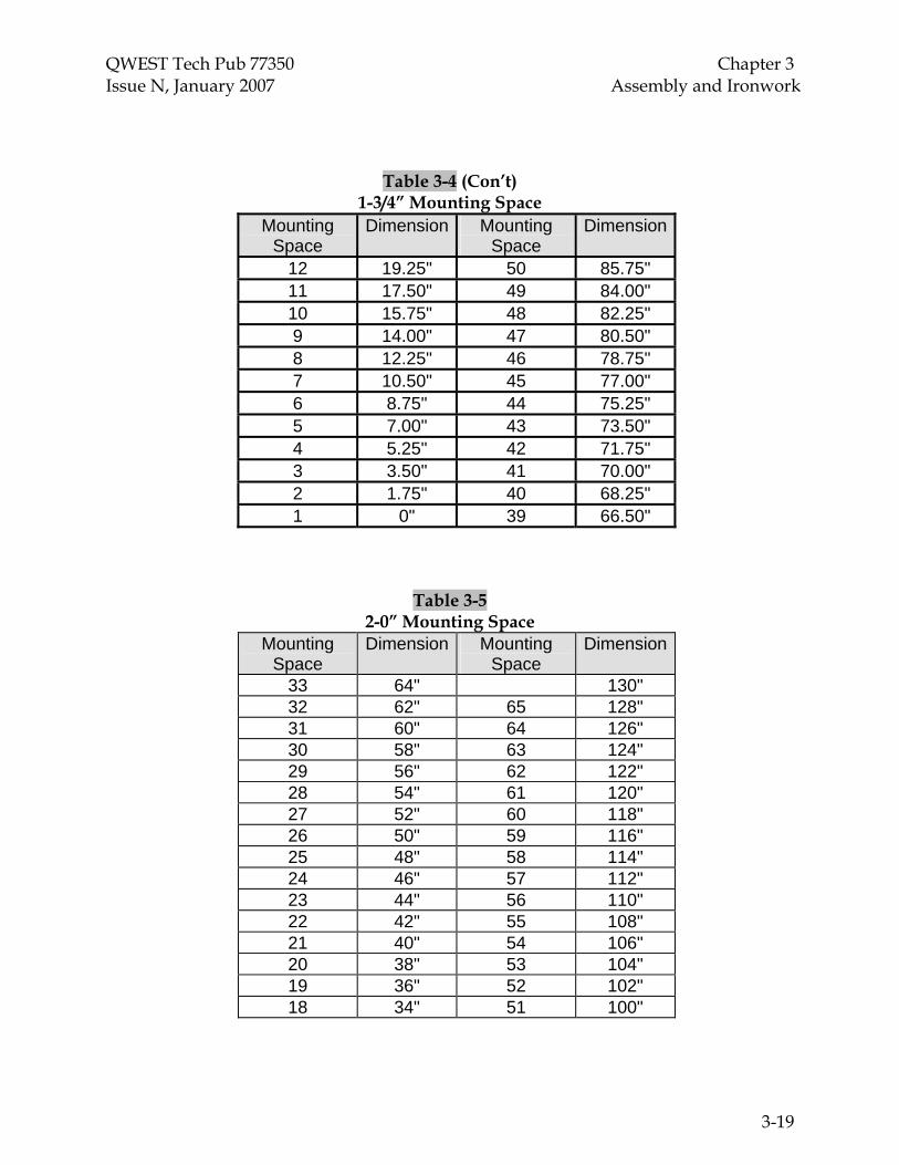
QWEST Tech Pub 77350 Chapter 3 Issue N, January 2007 Assembly and Ironwork
Table 3-4 (Con’t) 1-3/4” Mounting Space
Mounting Space
Dimension Mounting Space
Dimension
12 19.25" 50 85.75" 11 17.50" 49 84.00" 10 15.75" 48 82.25" 9 14.00" 47 80.50" 8 12.25" 46 78.75" 7 10.50" 45 77.00" 6 8.75" 44 75.25" 5 7.00" 43 73.50" 4 5.25" 42 71.75" 3 3.50" 41 70.00" 2 1.75" 40 68.25" 1 0" 39 66.50"
Table 3-5 2-0” Mounting Space
Mounting Space
Dimension Mounting Space
Dimension
33 64" 130" 32 62" 65 128" 31 60" 64 126" 30 58" 63 124" 29 56" 62 122" 28 54" 61 120" 27 52" 60 118" 26 50" 59 116" 25 48" 58 114" 24 46" 57 112" 23 44" 56 110" 22 42" 55 108" 21 40" 54 106" 20 38" 53 104" 19 36" 52 102" 18 34" 51 100"
3-19
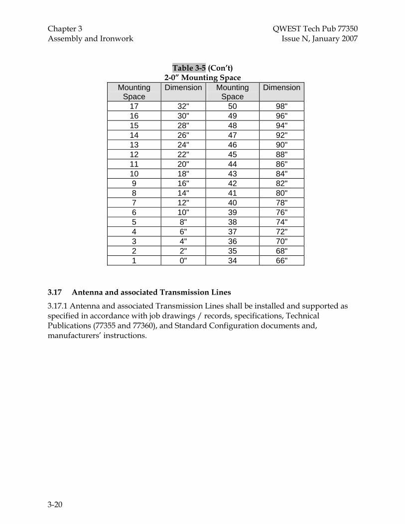
Chapter 3 QWEST Tech Pub 77350 Assembly and Ironwork Issue N, January 2007
Table 3-5 (Con’t) 2-0” Mounting Space
Mounting Space
Dimension Mounting Space
Dimension
17 32" 50 98" 16 30" 49 96" 15 28" 48 94" 14 26" 47 92" 13 24" 46 90" 12 22" 45 88" 11 20" 44 86" 10 18" 43 84" 9 16" 42 82" 8 14" 41 80" 7 12" 40 78" 6 10" 39 76" 5 8" 38 74" 4 6" 37 72" 3 4" 36 70" 2 2" 35 68" 1 0" 34 66"
3.17 Antenna and associated Transmission Lines
3.17.1 Antenna and associated Transmission Lines shall be installed and supported as specified in accordance with job drawings / records, specifications, Technical Publications (77355 and 77360), and Standard Configuration documents and, manufacturers’ instructions.
3-20

QWEST Tech Pub 77350 Chapter 3 Issue N, January 2007 Assembly and Ironwork
3.18 Earthquake Zone Map
45°
40°
35°
30°
120°
120°125°
115°
115°
110°
110°
105°
105°
100°
100°
95°
95°
30°
35°
40°
45°
90°
Black is Heavy Zone
White is Light Zone
3-21

Chapter 3 QWEST Tech Pub 77350 Assembly and Ironwork Issue N, January 2007 3.19 Alignment Tables
VERTICAL ALIGNMENT
Maximum Allowable Deviation From Plumb Height Maximum Allowable Deviation
4’6” or Less 1/16” Over 4’6” and
less than 7’ 1/8”
7’ to 9’ inclusive 3/16” Over 9’ 1/4”
HORIZONTAL ALIGNMENT Shall Be Level
3.20 Building Envelope Drilling Procedures
All drilling of the equipment building envelope, consisting of floors, walls, ceiling, or any wall/separation therein, shall be accomplished in a safe and environmentally sound manner, which captures and contains any debris using proper HEPA vacuum and protective materials.
All floor tiles shall be considered and treated as asbestos, unless identified as asbestos free.
These procedures shall be followed whenever the Service Supplier is performing an installation that involves drilling through floor tiles that contain asbestos or if the Service Supplier is unsure of the asbestos content of the floor tiles. See Chapter 12, “Central Office Equipment Removals/Installs and the Proper Handling of Hazardous Materials,” and RG 09-1031 Class 3 Asbestos Work Notification Form (Par. 14.1) for additional information.
3.20.1 Dry Drill Procedures
• Assemble tools and equipment: drill motor, drill bit, eye protection, petroleum jelly, spray detergent, paper wipes/towels, plastic locking seal bags, container (box) labeled with a Class 9 DOT label.
• Mark the floor tile where drilling is intended.
• Spread petroleum jelly in a five-inch diameter circle, 1/4” thick, surrounding the drilling point.
• Place the drill bit at the starting point and drill at the slowest practical speed. The early debris is the material from the tile. The later gray material is concrete dust formed into petroleum jelly slurry.
3-22

QWEST Tech Pub 77350 Chapter 3 Issue N, January 2007 Assembly and Ironwork • Remove the drill bit and wipe the floor and drill bit with paper wipes/towels. Clean
the resulting oily surfaces of the drill bit and floor with spray detergent.
• Place all used paper wipes/towels and filter from vacuum in a large plastic locking seal bag, place this bag into a second plastic locking seal bag, and place the bag in a properly-labeled asbestos container for disposal.
• Properly fill out a Straight Bill of Lading RG 33-0017, addressed to the BRI-MRC, and contact the MRC for pick up. Insert the following information in the Hazardous Materials section of RG 33-0017:
• Number and Units - number of containers
• Hazardous Materials - RQ, Asbestos, 9, NA2212, PG III
• Hazard Class - 9
• NA No. - NA2212
• Weight - estimated total weight of container
3.20.2 Wet Core Drilling Procedures
• 1. Assemble tools and equipment: drill stand, drill motor, core bit, water tank, vacuum pump, water collection kit, damp and dry paper wipes/towels, plastic locking seal bags, container (box) labeled with Class 9 DOT label.
• 2. Mark floor tile where drilling is intended.
• 3. Follow the manufacturer’s drilling procedures for setup, drilling, and wastewater collection.
• 4. When drilling is complete, vacuum any remaining water and clean up equipment with paper wipes/towels.
• 5. Follow procedures in 3.20.1, “Dry Drill Procedures,” steps 6 and 7.
3.21 Floor Anchors and Installation Instructions (Add sketch from -351 depicting floor anchor stagger placement)
Note: The requirements for floor anchors apply to equipment frames, stanchions, cabinets, DF frames, etc. Exceptions are allowed for anchoring ironwork assemblies, such as cable rack. Refer to TP77351, Chapter 6 for approved methods of anchoring ironwork.
There is one anchor bolt assembly approved for use within all Qwest telecommunications facilities. The only exception is the approved power equipment anchor for battery stands (see 3.21.1). For other power room specific frameworks (e.g., power boards, rectifiers and stanchions), the Service supplier will use the standard Hilti floor anchor with the red slip ring. The anchors are available in kit form containing two
3-23

Chapter 3 QWEST Tech Pub 77350 Assembly and Ironwork Issue N, January 2007 anchors and two 2” X 2” hold-down plates under Hilti® item #230712, Qwest PID #2285841. The anchor has a 2-1/2 inch (~70 mm) insertion depth and a 60mm embedment depth. The head of the torque-indicating anchor will break off at 60 foot pounds when installed correctly. For anchor bolt quantity and positioning information refer to the Qwest Technical Publication 77351. Frames and cabinet must be anchored prior to cable termination, top supporting, or junctioning to adjacent bays. If floor depth problems are encountered, the Service Supplier shall contact the Qwest Space Planner who will coordinate a resolution with the Qwest Real Estate Representative responsible for that office. Floor anchor holes shall not exceed the 70mm pilot hole depth of the anchor bolt assembly. The Installation service supplier shall document any applicable resolution in the Job Log.
3.21.1 All battery stands placed in any Qwest telecommunications power area will use the approved power equipment anchor. The only approved power equipment anchor is available in kit form from Hilti. Each kit contains two anchors and two 2” washers under Hilti item # 97413007. Two anchor bolts are required on each battery stand support footing in earthquake zone “Heavy” and one per footing in earthquake zone “Light.” Four anchor bolts are required for each power room bay in the earthquake zone “Heavy” and two anchor (positioned diagonally) in earthquake zone “Light” unless specified in Qwest Standard Configuration documents.
Note: All approved stanchions will use floor anchor assemblies depicted in Par. 3.21.
3.21.2 Drill the proper diameter and hole depth following the instructions in 3.20, “Building Envelope Drilling Procedures,” as appropriate.
3.21.3 Clean loose debris from the hole. Make sure all drilling debris is removed from the hole.
3.21.4 Make sure the nut and washer are threaded onto the rod with the washer in contact with the top of the sleeve. Any isolation bushings or hold down plates should not be on the anchor at this time.
3.21.5 Insert the anchor into the hole and tap the anchor down with a hammer until the washer contacts the concrete.
3.21.6 Pre-torque the anchor to approximately one half of its installation torque (30 foot pounds).
3.21.7 Loosen the nut several turns and then remove the rod, nut, and washer. The rod assembly may be backed out by using the screwdriver slot.
3.21.8 Position the frame, bay, or cabinet over the holes. Be careful not to let debris fall into the holes.
3.21.9 Place the rod through the hole in the base of the frame, bay, or cabinet and thread it into the anchor body until it is fully engaged in the threads in the bottom cone.
3-24

QWEST Tech Pub 77350 Chapter 3 Issue N, January 2007 Assembly and Ironwork 3.21.10 Add all components such as bushings, washers, and hold down plates.
3.21.11 Tighten the torque nut to the point where the top flange of the nut snaps off (approximately 60 foot pounds). Use a box end or a flare nut wrench or socket to tighten the torque nut. Do not use an open-end wrench, which may distort the torque nut and affect the setting torque. Any damage sustained to the red torque tamper indicator (green tamper indicator in power room applications) during the torquing process, or if the indicator is missing upon completion of the installation, will be deemed an improper anchor placement. If necessary, a replacement anchor may be required. 3.21.12 Prior to the start of battery stand installations, the Service Supplier will confirm that Hilti anchor bolt kit # 97413007 (green indicator) has been supplied with the job material. 3.22 Floor Anchor Bolt Modification Procedures
The Service Supplier may cut or modify floor anchor bolts in restricted applications only (e.g.; where the anchors installed in the base of the approved stanchions pose a potential safety/trip hazard and when the standard toll/switch floor anchors are used to anchor battery stands on uneven concrete floors where shimming is required) following the anchor manufacturer’s guidelines. The Service Supplier will adhere to the following procedures to ensure the minimization of airborne metal debris. Refer also to Par. 2.3.6.
3.22.1 Using a metal saw blade, cut the threaded rod at a minimum of two full threads extending beyond the nut. Take care to prevent the propagation of metal filings in the Central Office environment.
3.22.2 Do NOT use abrasive cutting blades, torch or any other heat source to cut the threaded rod after installation.
3.22.3 The cut end will have no exposed zinc plating. A protective coating (Qwest-approved touch-up paint for central office applications) shall be applied to that end to minimize oxidation.
3.23 Floor Tile Punch Procedure:
Tools needed:
• Approved Floor Punch
• A one-inch diameter punch.
• Heat Gun
• If available, use an approved heating device (i.e., heat gun) to heat the tile. Use heating device in accordance with manufacturer’s instruction.
3-25

Chapter 3 QWEST Tech Pub 77350 Assembly and Ironwork Issue N, January 2007
• Place floor tile punch on the area to be punched.
• Strike punch with a mallet while trying not to move the punch (if a heat gun is not available, 1 to 3 forceful strikes with a sharp punch will be needed to get through the floor tile. Additional strikes may cause splintering of the tile.)
• Remove the tile plug.
• If additional debris remains after punching, use spray detergent or HEPA vacuum (approved for use with asbestos) to clean up. If a HEPA vacuum is used for cleanup, the pre-labeled asbestos disposal container must be treated as asbestos waste and must not be emptied for re-use. Emptying the container could cause asbestos fiber release.
• Double bag plug and any asbestos debris that may remain. Ensure that the outer bag is properly labeled for asbestos disposal. Seal the bag and place in a storage area previously identified for asbestos waste. After several bags or containers (i.e., 4 or more) have been accumulated at the location, contact your local EHS or Environmental Manager for pickup and disposal according to local regulations (please call (UNICALL 800) 654-2525 for the area Manager).
Please note that the floor tile punch can also be used to fill in a plug of tile that has been removed previously:
• Chose the same size punch as the one that was used to remove the piece of tile.
• If there is a hole in the concrete underneath the tile layer, make sure that you have filled the hole with a stable material to prevent the plug from falling into the hole.
• Using the punch on an extra floor tile that may be available, follow the procedure listed above to create a plug.
• Apply an appropriate glue or mastic to the underlying material to hold the plug in place. Place the plug in the hole and tap gently into place with the mallet.
• Double bag, the asbestos debris and plug. Ensure that the outer bag is properly labeled for asbestos disposal. Seal the bag and place in a storage area previously identified for asbestos waste. After several bags (i.e., 4 small bags or more) have been accumulated at the location contact your local EHS or Environmental Manager for pickup and disposal according to local regulations (please call (UNICALL 800) 654-2525 for the area Manager).
3.24 Floor Tile Drilling With HEPA Vacuum Attachment
Floor tile drills with HEPA vacuum attachments, approved for use with asbestos, can be used if the collection container is pre-labeled for asbestos debris. The drill should be operated at the lowest speed practical to maximize the debris collected in the vacuum.
3-26

QWEST Tech Pub 77350 Chapter 3 Issue N, January 2007 Assembly and Ironwork Additional Considerations:
• To ensure that fiber release is minimized, ensure that the drill and attachment are working properly and are not clogged. If the vacuum attachment gets clogged, the obstructions must be cleared to maximize suction. Water should be sprayed onto the debris to minimize fiber release while the vacuum is being cleared.
• If the HEPA vacuum is not working properly, the procedure for use of a drill with petroleum jelly, “lubricant cable wire interduct” (PID# 2228122) must be used to reduce fiber exposures.
The pre-labeled asbestos disposal container must be treated as asbestos waste and must not be emptied for reuse. Emptying the container could cause unnecessary asbestos fiber release.
• Double bag any remaining asbestos debris. Ensure that the outer bag is properly labeled for asbestos disposal. Seal the bag and place in a storage area previously identified for asbestos waste. After several bags or containers (i.e. 4 or mom) have been accumulated at the location, contact your local EHS or Environmental Manager for pickup and disposal according to local regulations (please call (UNICALL 800) 654-2525 for the area Manager).
3.25 Floor Tile Drilling with Separate HEPA Vacuum not Attached to Tile Drill:
This method can be used when two technicians are available to perform the work. One employee would perform the drilling while the other holds the vacuum (equipped with a disposable container for asbestos wastes). The additional employee must operate the vacuum at the point to catch as much of the released debris as possible. If the vacuum becomes clogged, the obstructions must be cleared to maximize suction. Water should be sprayed onto the debris if there is a potential for fiber release while the vacuum is being cleared. If you cannot get the HEPA vacuum to work properly, follow the procedures for drilling through floor tile utilizing petroleum jelly to contain asbestos fibers.
The pre-labeled asbestos disposal container must be treated as asbestos waste and must not be emptied for re-use. Emptying the container could cause asbestos fiber release. Double bag any remaining asbestos debris or items used for cleanup. Ensure that the outer bag is properly labeled for asbestos disposal. Seal the bag and place in a storage area previously identified for asbestos waste. After several bags or containers (i.e. 4 or more) have been accumulated at the location, contact your local EHS or Environmental Manager for pickup and disposal according to local regulations (please call (UNICALL 800) 654-2525 for the area Manager).
3.26 Raised Floors
3-27

Chapter 3 QWEST Tech Pub 77350 Assembly and Ironwork Issue N, January 2007 When mounting frames, bays, or cabinets on raised floor environments, the floor manufacturer's and/or Qwest AMC requirements shall be followed. Where raised floors refer to ED4A306-70 for methods of support use Group 4 for light earthquake applications and Group 16 for heavy earthquake applications. Copies of ED4A306-70 can be obtained by contacting Lucent Technologies, Inc. at http://www.lucent.com/.
3.27 Waterproof Floor
3.27.1 Before drilling into any basement floor or basement wall, it shall be the installer's responsibility to determine from the Qwest Building Engineer whether or not waterproofing has been provided. Usually this is covered on job drawings or in job specifications.
3.27.2 When waterproofing is used, Qwest shall decide the method for securing the frames.
3.27.3 Drilling in waterproofed floors, where authorized, is limited to depths not exceeding three inches.
3.27.4 If the waterproofing cannot be temporarily broken to accept anchors, the “poured concrete block” method should be considered; however, some frames cannot be secured in this manner. See Qwest Communications Inc. Technical Publication 77351, “Qwest Central Office Telecommunications Equipment Engineering Standards.”
3.27.5 Frames equipped with pull out units, where an appreciable amount of the weight may be shifted outward, shall not be fastened with the “poured concrete block” method.
3.28 Battery Containment
3.28.1 Before drilling floors for new battery stands the installer shall determine if there are any containment requirements. This may include the entire room. After a floor containment system has been compromised the Real Estate department shall be notified to reestablish the containment.
3-28

QWEST Tech Pub 77350 Chapter 4 Issue N, January 2007 Cable Holes, Penetrations, and Fire/Smoke Protection
TOC4-i
4.3.7
CONTENTS
Chapter and Section Page
4. Cable Holes, Penetrations, and Fire/Smoke Protection.......................................4-1 4.1 General Requirements...................................................................................4-1 4.2 Closure Labels ................................................................................................4-2 4.3 Horizontal, Miscellaneous, and Vertical Penetrations .............................4-3 4.3.6 Intumescent Firestopping – Floor Penetrations………….………4-4
Intumescent Firestopping – Through Wall Penetrations…..…...4-5 4.4 Firestopped Penetration (Cable Hole) Designations ................................4-6 4.5 Approved Materials.......................................................................................4-6 4.6 Approved Label Template............................................................................4-6 4.7 Sample Application Exhibits ........................................................................4-7 4.8 Embargoing Blocked/Exhausted Cable Hole Penetrations.....................4-11
Figures 4-1 Intumescent Firestopping - Circular Opening With More Than One
Penetrating Item.........................................................................................................4-7
4-2 Intumescent Firestopping - Plastic or PVC Pipe in a Close Fitting Opening ....4-8
4-3 Intumescent Firestopping - Plastic or PVC Pipe in a Large Area Opening.......4-9
4-4 Floor Plan Sketch........................................................................................................4-10


QWEST Tech Pub 77350 Chapter 4 Issue N, January 2007 Cable Holes, Penetrations, and Fire/Smoke Protection
4-1
4. Cable Holes, Penetrations, and Fire/Smoke Protection
Note: All cable holes and penetrations that are opened shall be closed with the appropriate intumescent method and labeling requirements listed herein or defined in an Engineering Judgment document provided by the fire stop manufacturer. Approved fire stopping arrangements are based on the appropriate UL listed fire stopping assemblies as specified in Qwest’s Fire and Life Safety Practices “E-3 Fire and Smoke Stopping”.
The recommended method of fire / smoke stopping is accomplished with approved intumescent and endothermic materials and high temperature caulking compound.
Cable holes shall not be filled beyond ¾ capacity to allow for firestop to operate effectively.
Cable holes nearing or surpassing capacity will be brought to the attention of the Qwest representative responsible for Space Planning immediately.
All Service Suppliers are required to have trained, certified personnel when working on fire stopping. Personnel completing the 3M approved fire-stopping manufacturer’s seminar will be deemed certified to properly provide cable hole, penetration, and Fire/Smoke protection fire stopping.
The AMC Standard Configuration of some specific types of equipment and Qwest Drawing Standards can identify additional requirements beyond those documented in this chapter.
4.1 General Requirements
4.1.1 All cable holes, slots through floors and walls of interior spaces opened for installation purposes, occupied or not, shall be temporarily closed at the end of each working day and/or shift or whenever it is anticipated that no additional cable will be run that same day. Cables holes shall be permanently closed, using an approved method, when no further cable will be run on that specific job. (In “no case” should this exceed 5 days of inactivity before permanently sealing penetrations).
4.1.2 Job installation/removal work requires optimum fire protection to be maintained at all times.
4.1.3 The Service Supplier shall utilize Qwest approved fire/smoke stopping systems, which shall be properly installed to conform with their respective Underwriters Laboratory (UL) Listings.
4.1.4 Only one manufacturer’s fire/smoke stopping system shall be used to close any individual penetration. Mixing components from multiple manufacturers within a single penetration is strictly prohibited.
4.1.5 Intumescent and non-intumescent systems and putties shall not be mixed. Intumescent stopped holes shall use intumescent putty only. Putty shall be installed per manufacturers' instructions.

Chapter 4 QWEST Tech Pub 77350 Cable Holes, Penetrations, and Fire/Smoke Protection Issue N, January 2007
4-2
4.1.6 The installer shall refer to intumescent material manufacturer's “Application and Specification Guide” for specific requirements and instructions.
4.1.7 All cable holes and slots that utilize mineral wool bags shall have steel cover plates installed on both sides of the enclosure. Putty shall also be installed on both sides of the enclosure.
4.1.8 All penetrations shall be fire/smoke stopped using the approved intumescent method. Occupied cable holes utilizing wool bag type firestop materials shall be upgraded to preferred materials when opened for a cabling addition or as soon as practical.
4.1.9 All wood material used for construction of temporary walls and equipment or terminal mounting boards must be either UL listed fire retardant pressure treated and factory marked with the UL label or be completely coated with a fire retardant paint. Mounting boards should be kept to the minimum size required to mount equipment and allow for reasonable growth.
4.1.10 Cable temperature shall not exceed 115° Fahrenheit in any horizontal cable rack, vertical cable rack or vertical duct within the bay. In addition, there shall be no instance where an equipment surface temperature exceeds 115° Fahrenheit without a highly visible warning label.
4.1.11 For any work in a building that requires the use of Radiography or x-ray techniques by contractors or vendors for the purpose of locating building structural members and verifying core drill locations, following shall be part of the contractors specifications, and part of their MOP document for the work at hand.
• Prior to starting work Contractor must visually survey the building and the proposed work area for personnel exposure floor by floor and notify personnel about the potential for exposure to radiation and to assure that the exposure area is clear of personnel for the duration of the work.
• Prior to starting work Contractor must post warning signage on exterior doors or at safe perimeter distances from the exposure area to warn personnel. Example:
• "WARNING - Radiography is in Progress (on Floors 1, 2, 3, etc..)", or
• "WARNING - x-ray equipment is in use (on Floors 1, 2, 3, etc.)"
1. During each radiographic operation the contractor shall maintain continuous direct visual surveillance of the operation to protect against unauthorized entry into a high radiation area.
4.2 Closure Labels
Note: A template for labels is included with the cable hole application figures and may be reproduced on pressure sensitive paper for use. See Section 4.6.

QWEST Tech Pub 77350 Chapter 4 Issue N, January 2007 Cable Holes, Penetrations, and Fire/Smoke Protection
4-3
4.2.1 A green temporary closure tag shall be placed on or near any hole opened during the installation process. This tag shall be removed when the cable hole is permanently closed. It shall be permissible to use a reusable placard (magnetic or etched plastic) to satisfy this requirement. Temporary closures shall be made at the end of each working day or when no additional cable is to be run that same day. The bottom cover is not required for “temporary closures.”
4.2.1.1 Temporary closure requires that the top cover be secured with a minimum of five bolts (corners and center front) and that putty is installed around cables.
4.2.1.2 Temporary closures, associated with cable removals, require that an additional composite sheet be placed over the old sheet. This sheet shall be used to cover the void caused by the removal of cables. The additional sheet shall be bolted with a minimum of two bolts, and keep the gaps between the cables and the composite sheet one-half inch or less. Installer shall putty the void between the composite sheets and the cables.
4.2.1.3 The edge of the composite sheet against cables shall be taped with aluminum tape (1-2 mils thick), or plastic finger edging approved by the composite sheet manufacture. Protection is required to shield the cables from the composite sheet metal edges.
4.2.2 A red permanent closure tag shall be placed across the edge of a cable hole cover at the end of the installation process to assure that the label is destroyed if the cover is subsequently removed. This tag is required on both sides of the cable hole/penetration.
4.2.3 Closure labels shall have the following information: Qwest BVAPP number, supplier/organization name, telephone contact number, and date of closure. See Section 4.6 for labels.
4.3 Horizontal, Miscellaneous, and Vertical Penetrations
4.3.1 All cable slots, cable sleeves and openings through fire rated walls and floors including conduit runs, fiber optic distribution systems, and other openings require fire/smoke stopping.
4.3.2 All floor cable holes require a top cover of .112” thick steel sheet (.112 is an American Standard Preferred Thickness approximately related to AWG size 10.
4.3.3 All cable holes through fire rated walls require steel cover plates on each side of the penetration when the traditional method is used.
4.3.4 Temporary protection such as cones, posts, rails shall be provided for personnel and equipment where there is a danger of personnel or material falling through the cable hole.
4.3.5 Upon creating a floor or wall penetration, the location shall be identified as shown on the Floor Plan Drawing and shall be designated on both sides and will be fire stopped appropriately before end of shift.

Chapter 4 QWEST Tech Pub 77350 Cable Holes, Penetrations, and Fire/Smoke Protection Issue N, January 2007
4-4
4.3.6 Intumescent Firestopping - Floor Penetration Examples
Note: Refer to the applicable UL Listed assembly for the specific method required to suit the cable penetration configuration and office condition.
��
����
�������
��
����
Cable Tie - May Be Placed Directly Above Putty
2" - Typical For Putty Around CablesAnd At Interior Spaces
1" - Typical For Beads Of Putty At Perimeter of Cable BundleAnd Cable Hole Covers
Steel CableHole Cover10 Gauge
FirestopCertification Label Top Composite Sheet Cover
Putty - Perimeter ofCables At Top Cover
Cable Hole Designation
1/2" - Typical Space BetweenCable Bundle And Covers
IB6E1
A
Putty - Along CablesAt Sheathing Channel
Vertical Cable Rack
Cable HoleSheathing
Putty - At InteriorSpaces Between Cables
Composite Sheet Cover
A
1/4 x 1 1/4 FenderWashers
CS195CompositeSheet
Hole Spacing8" Maximum
Cable HoleDesignations areRequired. See
.5
Attached to BottomFlange, and PuttiedAgainst Cables
CS195 WireMesh InsideOf Penetration
02B5C
Section 3.3Par. 4.3.5
Note: Bottom composite sheet may be secured directly to bottom of cable hole. Bottom steel plate is not reinstalled.

QWEST Tech Pub 77350 Chapter 4 Issue N, January 2007 Cable Holes, Penetrations, and Fire/Smoke Protection
4-5

Chapter 4 QWEST Tech Pub 77350 Cable Holes, Penetrations, and Fire/Smoke Protection Issue N, January 2007
4-6
4.3.7 Intumescent Firestopping Example - Through Wall Penetrations
Reference Side B
Sec. A-A
Composite Cheet Cover OnBoth Sides of Opening
Reference Side A
Through Cable Rack
Putty - Around Perimeterof Cable Bundle And AtInterior Spaces BetweenCables
Putty - At PerimeterOf Cable Bundle
1/4 x 1/4 Sheet Metal ScrewRemovableComposite Sheet Cover
FirestopCertification Label
28 GA Sheet Metal Strip
StationaryComposite Sheet CoverWire Mest Side Into Penetration
Through Cable Rack
1/4" Wall Fastening1/4" Bolts with 1/4 x 1 1/4 Fender Washers
U S WEST Requires That All Wall Penetrations Be Provided With A Metal Flange
6"
2” Typical For
1” Typical For
Qwest
IB6W2
1/4 x 1 1/4 Fender Washer
3" Spacing
Cable HoleDesignationRequired
A
A
Mesh 02B5C
See 3.3.5See Par. 4.3.5

QWEST Tech Pub 77350 Chapter 4 Issue N, January 2007 Cable Holes, Penetrations, and Fire/Smoke Protection
4-7
4.4 Cable Hole / Penetration Designations
4.4.1 When cabling drawings/records do not show penetration location names, covers shall be designated per the following pattern (FFCCA) – FF=Floor, CC=Closest Column(s), A=Alpha (A thru Z) locations. A typical designation would be “02B5C.”
4.4.2 Floor penetration designations will be determined by the top cover location and will be applied to both sides of the penetration. All new and opened cable holes shall comply with this requirement. Refer to the Floor Plan Sketch Figure 4-4.
Note: TP 77353 Central Office Drawing Standards refers to a “Cap Delta” (Δ) symbol when describing fire-stopped cable hole penetrations on COE-FM floor plan drawings. This symbol is a drawing requirement only and the Service Supplier will not designate the cable hole covers with this symbol.
4.5 Approved Materials
UL listed Fire Protection Products approved for use in Telecommunication Buildings will be identified in Qwest Standard Configuration and technical reference documents.
4.6 Approved Label Template
RG 47-0132
CABLE HOLE OPEN
This cable hole is to be temporarily closed. Temporary closures shall be made at the end of each working day, when no additional cable is to be run that same day, or when period does not exceed 5 days and shall conform to Qwest Communications, Inc. Technical Publication 77350.
QWEST BVAPP NO.:_______________
SUPPLIER/ORGANIZATION:___________________________ CONTACT TELEPHONE:_______________________
DATE:__________
(GREEN)

Chapter 4 QWEST Tech Pub 77350 Cable Holes, Penetrations, and Fire/Smoke Protection Issue N, January 2007
4-8
RG 47-0133
FIRESTOPPED CABLE HOLE
This cable hole has been firestopped in accordance with Qwest Communications, Inc. Technical Publication 77350. QWEST BVAPP NO.:_______________
SUPPLIER/ORGANIZATION:___________________________ CONTACT TELEPHONE:_______________________
DATE:__________
(RED)
4.7 Sample Application Exhibits
Note: Refer to the applicable UL Listed assembly for the specific method required to suit the cable penetration configuration and office condition.
Figure 4-1 Intumescent Firestopping - Circular Opening with More Than One Penetrating Item

QWEST Tech Pub 77350 Chapter 4 Issue N, January 2007 Cable Holes, Penetrations, and Fire/Smoke Protection
4-9
Plastic Or PVC Pipe1/4" Fastener
Putty Or Caulk AroundPerimeter Of RestrictingCollar
Putty Putty
Metal ClampOr Steel Wire
Smoke Seal Putty
Intumescent Wrap
Restricting Collar
Putty around cable
Cable
Figure 4-2 Intumescent Firestopping - Plastic or PVC Pipe in a Close Fitting Opening

Chapter 4 QWEST Tech Pub 77350 Cable Holes, Penetrations, and Fire/Smoke Protection Issue N, January 2007
4-10
Plastic OrPVC Pipe
View A – A
Support Stirrup
1/4" Fastener
A A
Intumescent Wrap
1/4" Layer OfCaulk Or Putty
Figure 4-3 Intumescent Firestopping - Plastic or PVC Pipe in a Large Area Opening

QWEST Tech Pub 77350 Chapter 4 Issue N, January 2007 Cable Holes, Penetrations, and Fire/Smoke Protection
4-11
Northwest
Figure 4-4 Floor Plan Sketch depicting proper cable hole designations
Corner A3 A5
D3 D5 D4
C5 C4
B3 B5 B4
A4
Facilities without columns shall be laid out in a similar fashion. All measurements shall be taken from the Northwest corner. Cable holes shall be designated similar to these examples.
01B3A
01B3B
01B5A
C3
01C3A

Chapter 4 QWEST Tech Pub 77350 Cable Holes, Penetrations, and Fire/Smoke Protection Issue N, January 2007
4-12
4.8 Embargoing Blocked / Exhausted Cable Hole Penetrations
4.8.1 When cable penetrations become blocked due to their capacity limits being reached, the Service Supplier shall notify the Qwest Design Engineer listed on the face sheet of the DWP. The penetration will be identified on the Central Office drawings and in the field as an embargoed penetration. Running any additional cable of any type in an embargoed cable hole is strictly prohibited.

QWEST Tech Pub 77350 Chapter 5 Issue N, January 2007 Cabling, Forming, Running, and Securing
TOC 5-i
CONTENTS
Chapter and Section Page
5. Cabling, Forming, Running, and Securing.............................................................. 5-1 5.1 General Requirements.....................................................................................5-1 5.2 Cable Mining ....................................................................................................5-2 5.3 Bending and Forming......................................................................................5-3 5.4 Protection and Storage ....................................................................................5-4 5.5 Securing and Supporting ................................................................................5-5 5.6 Power cables .....................................................................................................5-6 5.7 Grounding Conductors ...................................................................................5-7 5.8 Cable Pile-up.....................................................................................................5-8 5.9 Coaxial Cables ..................................................................................................5-9 5.10 Fiber Optic Cable .............................................................................................5-9 5.11 Ribbon Cable...................................................................................................5-14 5.12 Repair of Damaged Cables ...........................................................................5-14 5.13 Spliced Cables, Splicing Systems, and Mated Connectable Cables ........5-14 5.14 Use of Nylon and Plastic Cable Ties ...........................................................5-15 5.15 Securing Tables...............................................................................................5-16 5.16 Securing Figures.............................................................................................5-18
Figures
5-1 Starting Stitch............................................................................................................. 5-18
5-2 Kansas City Stitch ..................................................................................................... 5-18
5-3 Sewing First Layer .................................................................................................... 5-19
5-4 Sewing Second Layer................................................................................................ 5-19
5-5 Supporting and Sewing Cables to Supports at Turns ......................................... 5-20
5-6 Securing Cable to Support with Kansas City Stitch............................................. 5-21
5-7 No. 9 Cord splice technique .................................................................................... 5-21
5-8 Chicago Stitch Used to Sew Cables Together ....................................................... 5-22
5-9 Banding of Cables with No. 9 cord......................................................................... 5-23

QWEST Tech Pub 77350 Chapter 5 Issue N, January 2007 Cabling, Forming, Running, and Securing
5-1
5. Cabling, Forming, Running, and Securing
Note: Additional requirements for power cabling are found in Chapter 9.
5.1 General Requirements The requirement for cable routing and segregation shall be per job specification and records/drawings, specified in Qwest Standard Configuration documents or technical publications.
Cables shall be run directly from point to point with only a “maintenance loop” of cable (not to exceed 4 feet) stored on the cable rack. All “maintenance loop” cabling must remain within the confines of the cable rack or designated cable support system.
Routing of cables between relay racks and frames without using the overhead cable support systems is prohibited (Unless specified in the Standard Configuration document). Placement of vertical splices, adapters on or in the relay rack uprights and cable ways and or horizontal/vertical cable support systems is prohibited. Unless specified in the AMC Standard Configuration the use of connectors in the frame/relay rack uprights is also prohibited
Note: If the AMC grants the Service Supplier a Letter of Deviation on running their cable in offices that have excessive build-up then that supplier shall document and place a copy of that waiver in the job package. 5.1.2 Supporting or securing of any cable to AC conduit is prohibited.
5.1.3 Remove all cable running tags and binder grouping material after the completion of testing. Exception: When requested by the Central Office Operations (COO) personnel and the Qwest Design Engineer concurs with a letter of deviation, on a per job basis, the tags may be left in place if those tags are made of a fire resistant material and will not inhibit the installation of future cable or restrict equipment maintenance. A copy of that waiver shall be placed in the job package. Refer also to Chapter 6, Par. 6.5.
5.1.4 Cable and cable management systems shall be at a distance sufficient to maintain a maximum cable/enclosure temperature of 115° F. At a minimum, the distance shall be no less than 6 inches of clearance from engine exhaust pipes, steam pipes, or other similar hazards.
5.1.5 Cable spanning horizontal planes shall not exceed 9 inches without additional support. Interim support points (auxiliary framing, conduit, etc.) must be installed so as not to interfere with future cross aisle cable racks or cable access to bays, cabinets, BDFB return bars, etc.
5.1.6 Where cables transition off a cable rack, they shall be routed over the side stringers or off the end of a cable rack that will not be extended at some future date. Cables shall not be routed through the cable rack with the exception of “unfused” battery cables where cable bending radius requirements can be maintained (refer to Par. 9.2.8). For

Chapter 5 QWEST Tech Pub 77350 Cabling, Forming, Running, and Securing Issue
5-2
N, January 2007
additional cable routing and transition requirements, refer to TP 77351 Chapter 6, Par. 6A.4.6. All cables dropping into a frame from a horizontal cable rack or duct system must be routed to align as directly above the frame upright or vertical duct system as possible. At no time will cable of any type make a horizontal transition greater than nine inches across the top of the bay to access the opposite bay upright or vertical duct arrangement. Overhead horizontal cable rack or duct systems must be extended beyond the location below where the cable will enter the bay upright or vertical duct.
5.1.7 All cable connections within a bay shall be supported within 24 inches of a point of termination.
5.1.8 Cables larger than No. 14 AWG must not be routed through a frame’s uprights. Cables smaller than No. 14 AWG, must not pass from the front of the bay to the rear (unless specified in Qwest Standard Configuration documents).
5.2 Cable Mining
5.2.1 Cable mining conducted above working equipment shall only be done after precautions are taken to protect the equipment below. A protective barrier shall be constructed between the cable rack and the equipment. Before any cables are removed, the cable racks shall be vacuumed with a High Efficiency Particulate Arrester (HEPA) vacuum.
5.2.1.1 The COO personnel will identify the critical equipment over which any cable mining activity must be performed in the Maintenance Window. The Service Supplier or contract agent will add this information to the Detailed MOP using the following format:
“List of Equipment on the Mining Route. Activity above this equipment must be performed in the Maintenance Window.”
Relay Rack and Equipment Description
RR# (s) __________ (DCS, Optical Terminal equipment, power plant
rectifiers, BDFB, synchronization, alarming, etc.)
This information must be entered into the Detailed MOP before any actual work steps or requirements are added. This is to recognize which equipment is considered “Critical Equipment” and where cable mining activities will be performed in the maintenance window.
NOTE: All other cable mining activities, assigned by this job, can be performed during normal business hours (including the restitching of cable racks after cables selected for removal are mined).
5.2.2 Ring or loop type cutters, which require the free end of the cable to be inserted through a ring or loop, shall be required for the removal of cable. Removal of cables shall have an authorized "Detailed" MOP written before any cable is removed.

QWEST Tech Pub 77350 Chapter 5 Issue N, January 2007 Cabling, Forming, Running, and Securing
5-3
5.2.3 A current probe or clamp on ammeter capable of reading both AC and DC currents shall be used to check for a zero current condition prior to the cutting of power/power return and grounding cables. The installer shall be required to designate the far-end termination on both sides of the power / grounding cable prior to the initial cut. This shall be documented in the "Detailed" MOP and a copy placed in the job package.
Note: Any power/power return and ground cable found without zero current flow shall be referred to Qwest Central Office Operations for de-energizing. If a grounding conductor is inadvertently energized, ensure that there is an adequate alternate current path prior to cutting it. Power cables (either the “hot” lead or the grounded return) that are going to be cut/removed and are still energized must be defused (or circuit breaker disabled) prior to the cut/removal.
5.2.4 All cables earmarked for removal/mining should be removed, where practical, to maintain cable pileup limits and safe loads. Where cabling cannot be removed without causing a service interruption, those cables shall be mined / removed to a minimum of the top of the cable rack where removal is not possible and the ends of all remaining cables shall be individually taped and tagged with far end information for future removal.
5.3 Bending and Forming
Note: Sharp bends in cables must be avoided to prevent damage to insulation and conductors.
Minimum Bending Radius for Cable and Wire Table Cable Type Bending Radius Switchboard / ABAM 3 Times Cable Diameter Shielded / Coaxial, Twin Conductor 10 Times Cable Diameter Power Cable 9 Times Cable Diameter (Refer to Par. 9.11) Armored Cable (BX), Flexible Steel 5 Times Cable Diameter Grounding Conductor 1 Foot Minimum (12 inches) Fiber Optic Bending Radius Single Fiber 1-1/2 inches Dual Fiber 2-3/4 inches Quad Fiber 3-5/16 inches 12-Count & Higher If manufacture’s requirements are not
specified, diameter times 10. Note: General Bending Rule, (for cable types not specified above) bending radius equals 10 times the diameter.

Chapter 5 QWEST Tech Pub 77350 Cabling, Forming, Running, and Securing Issue
5-4
N, January 2007
5.3.1 Earthquake Considerations Cabling between equipment elements that are secured to different earthquake planes (i.e. floor and ceiling) shall require additional slack between the cable break off and the equipment frame. Typically an additional 9 inch slack loop shall be provided.
5.4 Protection and Storage Protect all cables and wires against damage at all locations where they come in contact with sharp edges or threaded rod, using sheet fiber paper, plastic edge guard, and/or protective tubing as appropriate.
5.4.1 All cables stored for future use shall be identified at the point of termination with both far and near end location information. All cables shall be stored in a manner that allows for future access.
5.4.2 Cables run (extended), but not yet connected, shall be coiled, banded, and stored in a manner that shall not damage equipment or cause a safety hazard. Under no circumstances shall unconnected cables be stored in the cable rack system, in frame uprights, or vertical duct systems. Unconnected cables in cable support systems must be removed.
5.4.3 Plastic electrical tape or heat shrinkable tubing shall be used to wrap/protect the butt location of ABAM and shielded cables.
5.4.4 All cables shall have their exposed ends covered (taped) during the running process to protect existing equipment. The tape shall be left on until the cables are terminated. All cable running activities that have been determined to have the potential of damaging equipment or causing a safety hazard to personnel shall have an "Detailed” MOP written and authorized describing the hazards of how the supplier will handle the emergency situation.
5.4.5 Specific Locations Requiring Protection All types of cable rack that have threaded rod(s) within 3 inches of the cable rack shall have the threaded rod(s) protected with protective tubing. All tubing shall be installed prior to the start of cable running operations.
5.4.5.1 Provide protection using sheet fiber paper on inverted ladder-type cable rack in a horizontal or vertical plane where the wire and cable is in contact with the flange side of the cross straps.
5.4.5.2 Power wires fastened to the underside of channel type cable rack straps shall be protected.
5.4.5.3 Cables on distributing frames that are butted at the transverse arm require fiber protection or fanning rings.
5.4.5.4 Fanning rings shall be required when wires are fanned under transverse arms (i.e. when wires from one cable are terminated on multiple blocks).

QWEST Tech Pub 77350 Chapter 5 Issue N, January 2007 Cabling, Forming, Running, and Securing
5-5
5.4.6 Specific Cabling Requiring Protection All soft rubber insulated cables require protection when secured with No. 9-cord, or equivalent. Cable insulation that will not cold flow is exempt from this requirement. Cold flow is a condition where insulation thins or flows away from an impingement point.
5.4.6.1 All exposed ends of power/ground cables shall be protected with rubber insulating tape and plastic electrical tape or heat shrinkable end caps. The added insulating and protective covering shall be equivalent to the insulation and protective cover of the involved cable. This requirement applies specifically to common feeders serving multiple bays or cables that have been dead-ended.
5.5 Securing and Supporting 5.5.1 All switchboard cables and wires not in screened or panned and bracketed (with cable horns) are to be sewn with No. 9 cord (twine, waxed polyester, 9 ply) or equivalent. Horizontal runs are to be sewn every sixth strap and when necessary to keep cable in the cable rack or from sagging through the cable rack. Vertical runs and all waterfall type cable racks are to be sewn on alternate straps (typically beginning at least 2 straps prior to and ending 2 straps after the waterfall distance to maintain a smooth transition). To the extent possible and prudent, cables shall be sewn in complete layers the approximate width of the cable rack before starting additional layers. Installer may leave securing cord provided that an ending stitch is made and the cord is properly stored (secured back so that it doesn’t provide a safety hazard for equipment or personnel) for future use. No excess securing cord slack shall be allowed in equipment frames or on cable racks. No more than two square inches of cable shall be secured under a single stitch. Band between cable rack break-off and first frame support is exempt from the two square inch requirement.
5.5.2 All cables shall be tied with No. 9 cord, or equivalent, at cable rack break-off points, banded or tied between the cable rack and first support (where this distance exceeds eighteen inches), and tied at the first available support (cable support bracket) on a frame, bay, vertical fiber duct or cabinet. Where no cable support bracket exists, the Service Supplier may secure cabling through rear relay rack upright mounting holes or rear vertical fiber duct mounting holes to meet the eighteen-inch requirement provided that cable bending radius tolerances are maintained (refer also to par. 5.3). At the point of break-off the cable rack stringer (side of the cable rack) cables shall be bundled together and protected with sheet fiber paper or equivalent. When cable rack pileup prevents the installer from securing cables at the cable rack break-off, they shall be secured to the existing cables.
5.5.3 All non-fiber cables and wires shall be secured at intervals not to exceed three sheath feet in protected ducts or eighteen inches in open ducts and at all turns or junctions within the frame, bay, or cabinet.

Chapter 5 QWEST Tech Pub 77350 Cabling, Forming, Running, and Securing Issue
5-6
N, January 2007
5.5.4 Secure all cables at turns, before and after all turns and junctions of horizontal runs in other than pan, basket, and horned racks.
5.5.5 Cable shall not be unsupported for a distance greater than three sheath feet, measured from the last support on the cable rack or waterfall to the first support on the frame, bay, or relay rack, or vertical fiber duct except where otherwise specified in Standard Configurations, specifications or drawings.
5.5.6 Distributing frame cabling requires the securing of all cables on first and every alternate transverse arm, at break-off points, turns, and at the terminal strip location. Cables secured to horizontal transverse arm shall be secured according to the following table. Transverse arms on the horizontal side of the distribution frame shall have their cabling equally distributed across the served area. Cables are butted on the transverse arm at the point of break-off. Cable Ties shall not be used to secure cables on Distributing Frames. Cables shall be secured using No. 9 waxed cord or equivalent.
5.5.7. All cables shall be secured in a manner that affords access to the equipment.
Distribution Frames Cable and Wire Securing
How To Identify Need Securing Guidelines On transverse arms 5” or less Secure cable sheath within one-half inch
of butt. On transverse arms 5” to 12” in length
Secure cable sheaths within one-half inch of butt.
On transverse arms greater than 12” 1. Secure at cable turn 2. Secure at cable butt location 3. Secure midway between butt and turn
Frame vertical side Sew cables at alternate transverse arms Unsupported drop at bottom or top of frame
Maximum cable distance 3 sheath feet
Distribution of fanning rings No additional support required Wires that cross under a transverse arm at cable butt
Requires a fanning ring instead of butt fiber
5.6 Power Cables
The use of segregated cable racks for power is the first choice of installation in central offices. Where placement of a separate segregated power cable rack is not physically possible (some embedded 9’ or 11’6” environments) the following may apply with the approval of the Representative responsible for Common Systems engineering standards and the Design Engineer.

QWEST Tech Pub 77350 Chapter 5 Issue N, January 2007 Cabling, Forming, Running, and Securing
5-7
Power cables protected with 70 amp or less fuses / breakers may be run on cable racks utilized for switchboard cabling if they are sized at 4/0 or smaller. All power cables larger than 4/0 regardless of fuse / breaker size shall be run on dedicated FUSED POWER CABLE ONLY cable racks (per TP 77385). The placement of any type of cable used for anything other than power on FUSED POWER CABLE ONLY racks is strictly prohibited. New floor supported area build-outs will require segregated cable racking for power cable. The issuance of Letters of Deviation waving any of these requirements shall be considered invalid. Refer also to Par. 9.2.4.
5.6.1 Dedicated FUSED POWER CABLE ONLY cables racks shall not be equipped with screens, pans or cable horns. T-intersections and / or 90 degree turns in the racks require corner brackets in order to maintain the minimum-bending radius of larger size cables. All cabling on these racks shall be secured per table 5.15.
5.6.2 Power cables (Battery and Battery Return) on unsecured cable racks shall be closely coupled/paired and secured together at 24-inch intervals. Refer also to Par. 9.2.3 and 9.3.2.1.
5.6.3 Cables from the rectifiers to the battery, charge/discharge bus, between the battery stands and from the batteries to the distribution panels shall be on a separate cable rack from all other cables. These cables shall be referred to as UNFUSED POWER CABLES.
5.6.4 Vertical runs of power cable, which extend more than three floors, shall be provided with twenty feet of horizontal cable run out every third floor to alleviate weight buildup.
5.6.5 Power (battery and battery return) cables shall be supported within 24 inches of a point of termination.
5.6.6 Power alarm and monitoring leads run within power room locations only may be secured directly to cable rack stringers with No. 9 cord. Use of metal securing clips on cable rack stringers or auxiliary framing and/or nylon (or other) tie wraps for securing these leads is prohibited. Alarm and monitoring leads run outside of the power room environment shall be run on a dedicated switchboard cable rack where such switchboard cable rack exists.
5.7 Grounding Conductors 5.7.1 Grounding conductors 1/0 and smaller may be secured directly to the side of cable racks with cord or ties. See 5.11, “Use of Nylon and Plastic Cable Ties ”.
5.7.2 Grounding conductors larger than 1/0 shall be suspended on and secured to cable hangers. Cable hangers shall be placed at eighteen-inch intervals.
5.7.3 Grounding cables shall be supported within 24 inches from the point of termination.

Chapter 5 QWEST Tech Pub 77350 Cabling, Forming, Running, and Securing Issue
5-8
N, January 2007
5.8 Cable Pile-up
5.8.1 All cables shall be run within the confines of the cable rack stringers and shall not be run so as to block access to the entrance to of a bay. Do not run cables on existing cable racks where cable pileup exceeds cable pileup limits or the top of cable horns. Cable horns are limited to a maximum usable length of twelve inches
Note: Detailed cable pile-up information is documented in Technical Publication 77351, Chapter 6, 6A.4.1. Safe load limits is documented in Technical Publication 77351 Chapter 6A.3.
Switchboard/ABAM Cable Horizontal Cable Rack
Width of Cable Rack Supports on 5’1” Centers
Supports on 6’0” Centers
5” to 12” See 5.8.1 See 5.8.1 15” to 25” 12” 10”
30” 10” 7”
5.8.1 The maximum pile-up of switchboard, coax, ABAM, etc. allowed on cable rack 12 inches wide or less shall be no greater than the width of the cable rack.
Vertical Cable Rack 5.8.2 Vertical runs of Switchboard/ABAM type cables are is limited to 12 inches of pile up for cable racks 12 inches and larger.
Power Cable 5.8.3 The maximum pile-up on vertical or horizontal “Power Only” cable rack shall not exceed 7 inches.
Power Cable Pile-up (Horizontal and Vertical)
Width of Ladder Cable Rack
Maximum Depth of Cable Allowed
(Supports on 5’1” Centers
Maximum Depth of Cable Allowed
(Supports on 6’ Centers
12-20 Inches
(Solid Stringer Only)
7 Inches 7 Inches
25-30 Inches
(Reinforced Only)
7 Inches 7 Inches
5.8.4 The maximum width of horizontal and vertical dedicated power cable rack shall not exceed 20 inches before converting to a reinforced cable rack. Any dedicated power cable rack 25 inches in width or larger shall be a reinforced cable rack. All power cable rack shall be solid stringer type only.

QWEST Tech Pub 77350 Chapter 5 Issue N, January 2007 Cabling, Forming, Running, and Securing
5-9
5.8.5 The maximum pile-up on cable hangers or “T” bars shall be limited to 2 1/2 inches. One-inch cable minimum clearance shall be maintained between hanger and supporting cable rack stringer. The maximum pile-up on cable brackets or hangers shall not exceed the manufacturers recommended weight restriction or the width of the bracket which ever is more stringent.
5.8.6 Fiber Optic Riser Type Cable Pile-up (Horizontal and Vertical)
Width of Ladder Fiber Cable Rack
Maximum Depth of Cable Allowed
(Supports on 5’1” Centers)
Maximum Depth of Cable Allowed
(Supports on 6’ Centers)
5 Inches 5 Inches 5 Inches
12-20 Inches 7 Inches 7 Inches
5.9 Coaxial Cables
5.9.1 Coaxial cables may be run with other types of switchboard. Coaxial cables shall not be run on “Fiber Optic Only” or “Power Only” cable rack.
5.9.2 Care shall be taken, when sewing or banding, not to indent or collapse cables.
5.10 Fiber Optic Cable 5.10.1 Upon receipt of fiber optic cables for installation, Service Supplier shall conduct a walk through of the cable route. The Service Supplier shall inform The Qwest Design Engineer of any fiber cable that exceeds acceptable slack limits referenced in Paragraph 5.10.4.
5.10.2 Wherever fiber cables may come in contact with any sharp or metal edge, the cable shall be protected with sheet fiber paper or equivalent. Fiber jumpers and cables shall be protected from lacing twine by wrapping the fiber in one layer of sheet fiber paper.
5.10.3 Fiber Optic Intra-office Riser cables and jumpers shall not be pulled or twisted during installation. Fiber cable (12 fiber and smaller) must be bundled together and loosely secured every 6’ along horizontal cable support systems to prevent coiling or snagging. Manufacturers' guidelines regarding bend radius shall be followed at all times where these requirements are more stringent than those listed in this chapter.
5.10.4 Fiber Optic Cable slack storage within dedicated, segregated fiber-only cable racks or fiber duct-type protection systems is strictly prohibited. Fiber optic cable slack shall be stored in approved slack storage panels and facilities only. The looping of fiber cables (within any dedicated fiber duct or cable rack system) is strictly prohibited. Fiber jumper slack shall be stored on reels or trays, specifically designed for that purpose. Only Qwest-approved fiber cable support systems and slack storage units may be used within Central Office environments. Slack lengths stored in the horizontal trough

Chapter 5 QWEST Tech Pub 77350 Cabling, Forming, Running, and Securing Issue
5-10
N, January 2007
system or on the “Fiber Optic Cable Only” Cable” rack shall not be looped and will adhere to the following examples:
Note: Acceptable fiber cable slack limits within horizontal sections of “Fiber Only Cable” rack or trough systems will be equal to or less than those stated in the following tables.
Maximum Fiber Cable Slack Lengths per Fiber Cable (Within “Fiber-Only” Cable Racks): Run Length
in Meters Run Length In
Feet Maximum Slack In Feet (Meters)
1-15 ∼3.3’ to ∼50’ 2’ (∼.6m) 16-25 ∼53’ to ∼ 82’ 3’ (∼.9m) 26-50 ∼85’ to ∼164’ 5’ (∼1.5m) 51-75 ∼167’ to ∼246’ 7’ (∼2.1m) > 76 >∼250’ 10’ (∼3m)
Maximum Fiber Cable Slack Lengths per Fiber Cable
(Within “Fiber Duct-Type” Cable Racks): Run Length
in Meters Run Length In
Feet Maximum Slack In Feet (Meters)
1-15 ∼3.3’ to ∼50’ 1’ (∼.3m)

QWEST Tech Pub 77350 Chapter 5 Issue N, January 2007 Cabling, Forming, Running, and Securing
5-11
16-25 ∼53’ to ∼82’ 2’ (∼.6m) 26-50 ∼85’ to ∼164’ 3’ (∼.9m) > 51 >∼167’ 5’ (∼1.5m)
5.10.5 Cable ties shall not be used for banding or securing fiber optic cables/jumpers.
5.10.6 Multi-Fiber cable counts (24 and larger) no longer require the placing of sheet fiber paper as a means of protection (encircling each cable before it is secured with No. 9 lacing cord) against central office ironwork (e.g., cable rack and auxiliary framing).
Note: Standard lacing requirements, however, still do apply to these cables at every fourth cross strap on horizontally-positioned cable racks and at every cross strap on vertically-positioned cable racks. Single fiber optic cables and smaller multi-fiber cable counts (< 24) will still require the placing of sheet fiber paper for protection at the same securing points listed above.
5.10.7 Metallic type fiber optic cables shall be grounded. Components include: protective cable covering, cable sheath and/or any metallic inner strength members.
5.10.8 Fiber optic cable bend radius shall not be less than the fiber cable manufacturer’s published minimum or than the minimums listed below:
• Simplex cable 1 1/2 inch radius
• Duplex cable 2 3/4 inch radius
• Quad 3 5/16 inch radius
• General rule: bending radius (where not otherwise specified) = 10 times the diameter of the cable/lead.
5.10.9 All 90-degree corners used to route and support fiber cables on “FIBER OPTIC CABLE ONLY” cable racks must be equipped with corner brackets. Fiber cables are routed around the corners using the approved corner brackets.
5.10.10 New cable racks installed to support fiber optic cables must be dedicated for that purpose. Placing intra-office fiber optic cables with copper cables on the same cable rack is strictly prohibited. All new fiber cable racks will be dedicated, segregated orange ladder type (solid stringer only) equipped with orange plastic kydex pan and cable horns. The standard size cable rack for fiber optic cables in 7’ floor-supported systems is 20” (unless specific office conditions, Qwest capacity decisions, or Qwest Standard Configuration documents dictate otherwise). Fiber optic cables run horizontally on these racks are not secured except where the cable breaks onto or off of the cable rack. At these points, the fiber cable will be wrapped with a layer of sheet fiber paper and secured to the cable rack stringers, or transition bracket while maintaining the minimum bend radius.
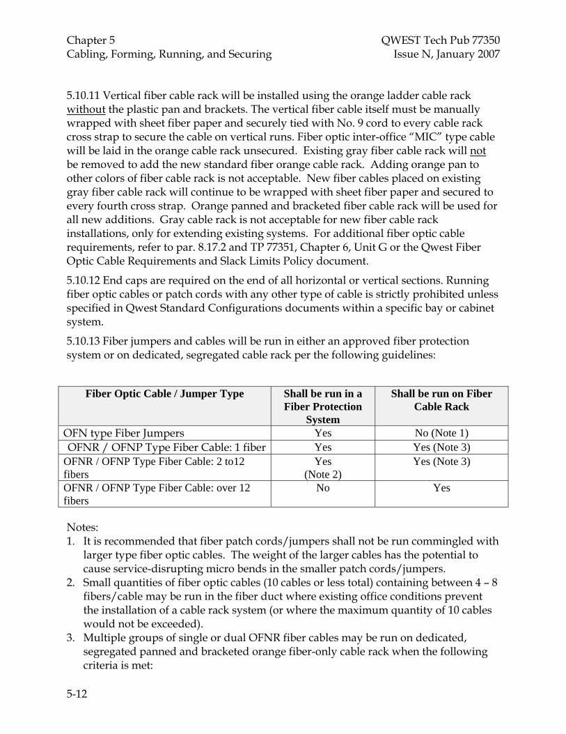
Chapter 5 QWEST Tech Pub 77350 Cabling, Forming, Running, and Securing Issue
5-12
N, January 2007
5.10.11 Vertical fiber cable rack will be installed using the orange ladder cable rack without the plastic pan and brackets. The vertical fiber cable itself must be manually wrapped with sheet fiber paper and securely tied with No. 9 cord to every cable rack cross strap to secure the cable on vertical runs. Fiber optic inter-office “MIC” type cable will be laid in the orange cable rack unsecured. Existing gray fiber cable rack will not be removed to add the new standard fiber orange cable rack. Adding orange pan to other colors of fiber cable rack is not acceptable. New fiber cables placed on existing gray fiber cable rack will continue to be wrapped with sheet fiber paper and secured to every fourth cross strap. Orange panned and bracketed fiber cable rack will be used for all new additions. Gray cable rack is not acceptable for new fiber cable rack installations, only for extending existing systems. For additional fiber optic cable requirements, refer to par. 8.17.2 and TP 77351, Chapter 6, Unit G or the Qwest Fiber Optic Cable Requirements and Slack Limits Policy document.
5.10.12 End caps are required on the end of all horizontal or vertical sections. Running fiber optic cables or patch cords with any other type of cable is strictly prohibited unless specified in Qwest Standard Configurations documents within a specific bay or cabinet system.
5.10.13 Fiber jumpers and cables will be run in either an approved fiber protection system or on dedicated, segregated cable rack per the following guidelines:
Fiber Optic Cable / Jumper Type
Shall be run in a Fiber Protection
System
Shall be run on Fiber Cable Rack
OFN type Fiber Jumpers Yes No (Note 1) OFNR / OFNP Type Fiber Cable: 1 fiber Yes Yes (Note 3)
OFNR / OFNP Type Fiber Cable: 2 to12 fibers
Yes (Note 2)
Yes (Note 3)
OFNR / OFNP Type Fiber Cable: over 12 fibers
No Yes
Notes: 1. It is recommended that fiber patch cords/jumpers shall not be run commingled with
larger type fiber optic cables. The weight of the larger cables has the potential to cause service-disrupting micro bends in the smaller patch cords/jumpers.
2. Small quantities of fiber optic cables (10 cables or less total) containing between 4 – 8 fibers/cable may be run in the fiber duct where existing office conditions prevent the installation of a cable rack system (or where the maximum quantity of 10 cables would not be exceeded).
3. Multiple groups of single or dual OFNR fiber cables may be run on dedicated, segregated panned and bracketed orange fiber-only cable rack when the following criteria is met:
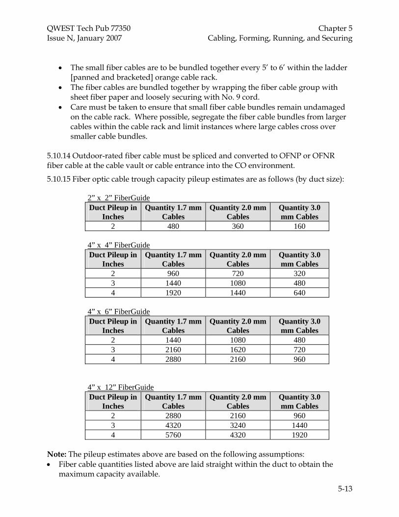
QWEST Tech Pub 77350 Chapter 5 Issue N, January 2007 Cabling, Forming, Running, and Securing
5-13
• The small fiber cables are to be bundled together every 5’ to 6’ within the ladder [panned and bracketed] orange cable rack.
• The fiber cables are bundled together by wrapping the fiber cable group with sheet fiber paper and loosely securing with No. 9 cord.
• Care must be taken to ensure that small fiber cable bundles remain undamaged on the cable rack. Where possible, segregate the fiber cable bundles from larger cables within the cable rack and limit instances where large cables cross over smaller cable bundles.
5.10.14 Outdoor-rated fiber cable must be spliced and converted to OFNP or OFNR fiber cable at the cable vault or cable entrance into the CO environment.
5.10.15 Fiber optic cable trough capacity pileup estimates are as follows (by duct size):
2” x 2” FiberGuide Duct Pileup in
Inches Quantity 1.7 mm
Cables Quantity 2.0 mm
Cables Quantity 3.0 mm Cables
2 480 360 160 4” x 4” FiberGuide Duct Pileup in
Inches Quantity 1.7 mm
Cables Quantity 2.0 mm
Cables Quantity 3.0 mm Cables
2 960 720 320 3 1440 1080 480 4 1920 1440 640
4” x 6” FiberGuide Duct Pileup in
Inches Quantity 1.7 mm
Cables Quantity 2.0 mm
Cables Quantity 3.0 mm Cables
2 1440 1080 480 3 2160 1620 720 4 2880 2160 960
4” x 12” FiberGuide Duct Pileup in
Inches Quantity 1.7 mm
Cables Quantity 2.0 mm
Cables Quantity 3.0 mm Cables
2 2880 2160 960 3 4320 3240 1440 4 5760 4320 1920
Note: The pileup estimates above are based on the following assumptions: • Fiber cable quantities listed above are laid straight within the duct to obtain the
maximum capacity available.

Chapter 5 QWEST Tech Pub 77350 Cabling, Forming, Running, and Securing Issue
5-14
N, January 2007
• Fiber cables are singles or small “duals” only. • These estimates apply only to horizontal sections of fiber duct. • All fiber cables placed in the trough are the size indicated.
5.11 Ribbon Cable Some Fiber Optic Ribbon type cables can be run on dedicated fiber cable rack. For detailed specifications on fiber optic cable approved for use within central offices and buildings, contact the Qwest representative for fiber cable standards or technology selection. All other fiber ribbon cables shall be placed in dedicated cableways and labeled for fiber optic ribbon cables only.
5.12 Repair of Damaged Cables 5.12.1 Damaged outer jackets of Polyvinyl Chloride (PVC) covered cables shall be repaired with electrical tape. The tape shall be applied in two half-lapped layers with the final two wraps applied without tension and overlapping. The tape shall extend a minimum of two inches past the damaged section.
5.12.2 Seriously damaged sections of outer jackets of PVC covered cables shall be repaired by removing the damaged section and replacing it with the covering from a similar cable. Apply a single half-lapped layer of electrical tape over the new section, extending two inches either side of the repaired section, to secure it in place.
5.12.3 Damaged outer jackets of power cable shall be repaired with an insulation equivalent to that of the original insulation or with an insulating device identified for the purpose. Heat shrink tubing and/or electrical tape are approved for this use.
5.12.4 A run of cable shall be replaced if the number of damaged conductors exceeds five percent of total conductors.
5.12.5 Repair of damaged fiber cables must be evaluated (for loss characteristics) and approved by the AMC Representative responsible for fiber cable standards prior to installation.
5.13 Spliced Cables, Splicing Systems, and Mated Connectable Cables 5.13.1 Multi-conductor cable shall be rerun if the number of spliced conductors exceeds five percent of the conductors in the cable. Under certain conditions, this requirement may be deviated from with permission of the Qwest Design Engineer or the use of an approved cable splicing system. A letter of variance shall be required and the reason for not rerunning the cable shall be documented in the job log.
5.13.2 Splicing of any type of cables shall be kept to a minimum and, if required, shall be done at the equipment shelf or approved splice shelf. All splices shall be protected. Splices shall not appear on the cabling surface of cable racks.

QWEST Tech Pub 77350 Chapter 5 Issue N, January 2007 Cabling, Forming, Running, and Securing
5-15
5.13.3 Mating of connectable cables shall be kept to a minimum and if required shall be done at the equipment shelf. Connectors shall not appear on the cabling surface of a cable rack and only in the vertical upright of frames, bays or cabinets when specified in the AMC Standard Configuration.
5.13.4 Mated connectable cables shall be mated and secured by using twine, tie wraps, hook and loop systems, screws, spring clips, clear heat shrink etc.
5.13.5 Spliced or mated cables shall be protected, designated (location, type, functionality), and be accessible for maintenance. Splices or mated cables that are stored in cableways, or dispersed throughout the equipment facility shall require a “Master Location List” (RG47-0156). The “Master Location List”, shall show all splice number, splice locations, splice type, and functionality of the spliced circuit. The “Master Location List” shall reside at the same facility and be available to those with a need for the information. Splice locations shall also be designated to show exact location of the splice. Designations shall be visible from the floor, and are require a minimum designation of a Master Location List reference number. Splice connections shall have sufficient slack at the splice point for maintenance. Splicing fiber optic cables are only permitted within approved splice shelves.
5.13.6 Protective covers or caps shall be installed on unused connectors to protect contacts from mechanical or ESD damage.
5.14 Use of Nylon and Plastic Cable Ties 5.14.1 Cable ties are not approved for securing or banding of cables in cable racks or securing fiber optic cables and jumpers.
5.14.2 Cable ties used for banding and securing of cable, PVC protection etc. shall be of an adequate size, type, strength, etc. for the particular application. Tightening cable ties to the point of damaging the cable is strictly prohibited.
5.14.3 Cable ties shall be trimmed at the locking head with a flush cutting device that provides automatic tensioning.
5.14.4 Under no circumstances shall cable ties have sharp or jagged cut ends protruding from the locking head. A cable tie is considered to have sharp or jagged ends when it is sharp to the touch.
5.14.5 The locking head of reusable cable ties shall be positioned so as not to interfere with the installation or removal of apparatus or equipment
5.14.6 Reusable cable tie tails shall be positioned so as not to present a personnel hazard.
5.14.7 When superimposing additional cable or wire to forms, existing cable ties shall be removed where the heads of tie wraps interfere with additional cable or wires.
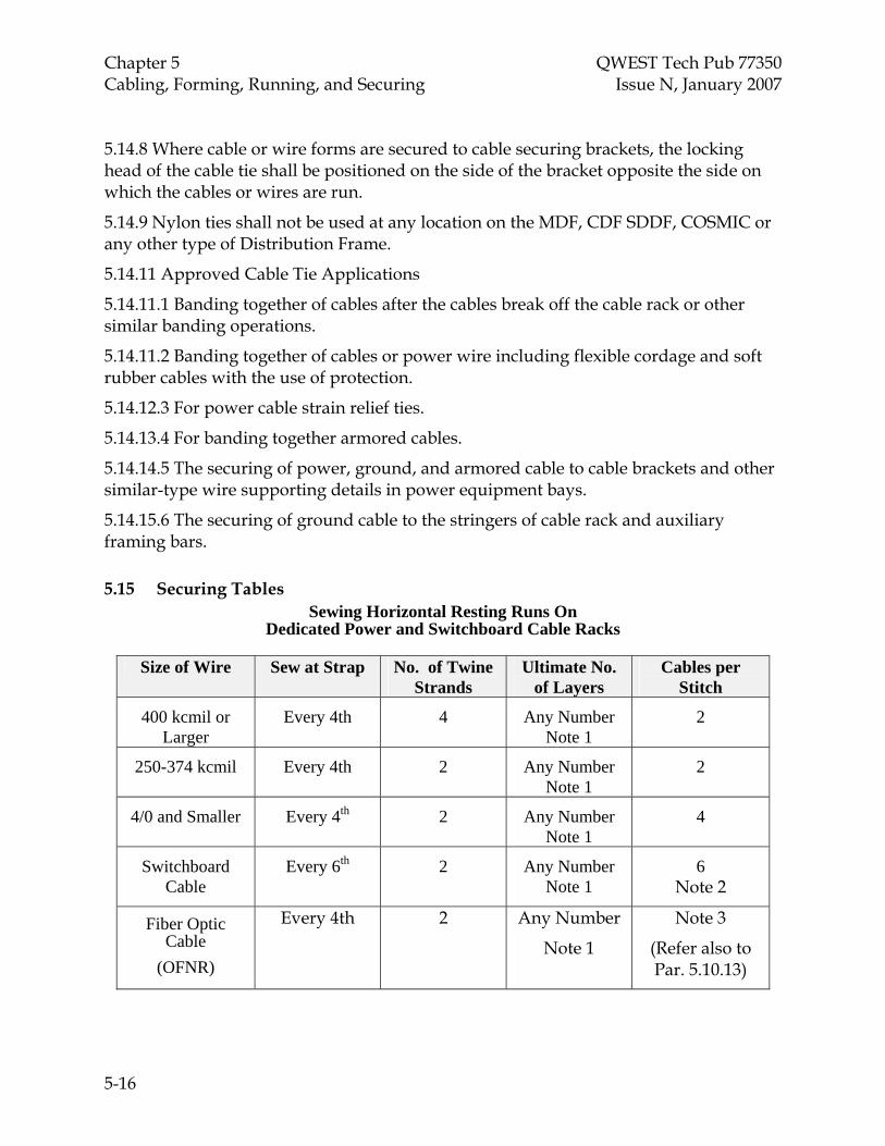
Chapter 5 QWEST Tech Pub 77350 Cabling, Forming, Running, and Securing Issue
5-16
N, January 2007
5.14.8 Where cable or wire forms are secured to cable securing brackets, the locking head of the cable tie shall be positioned on the side of the bracket opposite the side on which the cables or wires are run.
5.14.9 Nylon ties shall not be used at any location on the MDF, CDF SDDF, COSMIC or any other type of Distribution Frame.
5.14.11 Approved Cable Tie Applications
5.14.11.1 Banding together of cables after the cables break off the cable rack or other similar banding operations.
5.14.11.2 Banding together of cables or power wire including flexible cordage and soft rubber cables with the use of protection.
5.14.12.3 For power cable strain relief ties.
5.14.13.4 For banding together armored cables.
5.14.14.5 The securing of power, ground, and armored cable to cable brackets and other similar-type wire supporting details in power equipment bays.
5.14.15.6 The securing of ground cable to the stringers of cable rack and auxiliary framing bars.
5.15 Securing Tables Sewing Horizontal Resting Runs On
Dedicated Power and Switchboard Cable Racks
Size of Wire Sew at Strap No. of Twine Strands
Ultimate No. of Layers
Cables per Stitch
400 kcmil or Larger
Every 4th 4 Any Number Note 1
2
250-374 kcmil Every 4th 2 Any Number Note 1
2
4/0 and Smaller Every 4th 2 Any Number Note 1
4
Switchboard Cable
Every 6th 2 Any Number Note 1
6 Note 2
Fiber Optic Cable
(OFNR)
Every 4th 2 Any Number
Note 1
Note 3
(Refer also to Par. 5.10.13)

QWEST Tech Pub 77350 Chapter 5 Issue N, January 2007 Cabling, Forming, Running, and Securing
5-17
Sewing Vertical Or Inverted Horizontal Runs
On Dedicated Power and Switchboard Cable Racks
Size of Wire Sew at Strap Number of Twine Strands
Ultimate Number of
Layers
Cables per Stitch
250 kcmil or Larger
Every Strap 4 Note 1 1
4/0 - #4 Every Strap 2 Note 1 2
#6 and Smaller Every Strap 2 Note 1 Note 2 Switchboard
Cable Alternate Strap 2 Note 1 4
Note 2 Fiber Optic
Cable (OFNR)
Every 4th 2 Any Number
Note 1
Note 3
(Refer also to Par. 5.10.13)
Sewing on Horizontal Runs of Cable Hangers
Cable Hangers Spaced at 18” Intervals
Size of Wire Sew at Strap Number of Twine Strands
Ultimate Number of
Layers
Cables per Stitch
250 kcmil or larger
Every Hanger 2 Note 1 1
4/0 and smaller Every Hanger 2 Note 1 2 Note 2
Notes:
1. Limited by Par. 5.8.6, “Cable Pile-up,” requirements.
2. Cables under a single stitch shall not exceed two square inches.
3. Quantities of single fibers (1 - 12) can be loosely secured together provided they do not exceed 1 square inch per stitch. Fiber optic cables containing between 24 – 72 fibers will be secured at 2 cables per stitch.

Chapter 5 QWEST Tech Pub 77350 Cabling, Forming, Running, and Securing Issue
5-18
N, January 2007
5.16 Cable Securing Figures

QWEST Tech Pub 77350 Chapter 5 Issue N, January 2007 Cabling, Forming, Running, and Securing
5-19

Chapter 5 QWEST Tech Pub 77350 Cabling, Forming, Running, and Securing Issue
5-20
N, January 2007

QWEST Tech Pub 77350 Chapter 5 Issue N, January 2007 Cabling, Forming, Running, and Securing
5-21

Chapter 5 QWEST Tech Pub 77350 Cabling, Forming, Running, and Securing Issue
N, January 2007
5-22

QWEST Tech Pub 77350 Chapter 5 Issue N, January 2007 Cabling, Forming, Running, and Securing
5-23

Chapter 5 QWEST Tech Pub 77350 Cabling, Forming, Running, and Securing Issue
5-24
N, January 2007

QWEST Tech Pub 77350 Chapter 6 Issue N, January 2007 Wiring
TOC 6-i
CONTENTS
Chapter and Section Page
6. Wiring ............................................................................................................................6-1 6.1 General Requirements.....................................................................................6-1 6.2 Fanned and Unsewed Forms..........................................................................6-1 6.3 Sewed Forms.....................................................................................................6-1 6.4 Protection ..........................................................................................................6-2 6.5 Cable Tags .........................................................................................................6-2

QWEST Tech Pub 77350 Chapter 6 Issue N, January 2007 Wiring
6-1
6. Wiring
6.1 General Requirements 6.1.1 All equipment installed shall have the all wiring run and terminated to the locations specified using the type, color, and gauge specified in the drawings/records and/or manufacturer's specifications and instructions.
6.1.2 Wire shall be neatly dressed in such a manner as to avoid congestion, to ensure accessibility, and to maintain clearance between terminals.
6.1.3 All spare and unused wire shall be placed in fiber/protective tubing or secured to the existing form or equipment. The Service Supplier also has the option of cutting/ trimming back spare wiring at the cable butt location. All bare wire ends shall be insulated. This requirement shall also apply to spares within a frame distribution block enclosure.
Note: Under no circumstances shall spared wiring be coiled around in-service wiring.
6.1.4 Where a functional performance test is not performed, a continuity test shall be made on all conductors run and connected by the Installer, this test shall be made with appropriate test equipment (Manufacturers continuity test card - I.E. streaker). Functional performance and continuity testing shall be recorded on RG47-0157 “Test Record (COE)”; Copy of test records shall be left in Job Packet.
6.1.5 Wires connected in distribution frame blocks shall be dressed to allow visual inspection of terminal connections.
6.1.6 Wire dress shall be sufficient to provide for one only additional skinner length without splicing the conductor.
6.1.7 Wire shall be both listed and rated for the application.
6.2 Fanned and Unsewed Forms 6.2.1 Fanning rings shall be placed as provided in job specifications prior to wiring operations.
6.2.2 Provide fiber protection at butt locations on transverse arms of distributing frames where fanning rings are not used. When cable wiring fans under the transverse arm, fanning rings are required.
6.2.3 Loose wires not held in place by rings or other similar retaining devices shall be banded at each point of breakout.
6.3 Sewed Forms 6.3.1 Shall be secured in a manner that avoids congestion and affords access to the equipment.
6.3.2 All wiring added to existing forms shall be neatly dressed and properly secured.

Chapter 6 QWEST Tech Pub 77350 Wiring Issue N, January 2007
6-2
6.3.3 All ending stitches shall be trimmed of excess twine.
6.3.4 Forms designed for hinged equipment shall be capable of accomplishing movement without twisting or damage to the form.
6.4 Protection All wiring shall be protected from hazardous conditions such as sharp edges, excessive strain, etc.
6.5 Cable Tags All temporary installation cable running tags must be removed prior to job completion and turnover. An exception to this standard is permitted when the CO Operations representative requests that the cable running tags remain in place for future use (e.g., CLEC Decommission activity). Refer also to Par. 8.19.6; 8.24; and Par. 16.5.
Note: Cable tags attached by the manufacturer that contain circuit identification information are not cable running tags and will not be removed.

QWEST Tech Pub 77350 Chapter 7 Issue N, January 2007 Connecting
TOC 7-i
CONTENTS
Chapter and Section Page
7. Connecting ...................................................................................................................7-1 7.1 General Requirements................................................................................7-1 7.2 Coaxial Connections and Test/Turn-up Parameters.............................7-1 7.3 Connectable Cables.....................................................................................7-3 7.4 Crimp Compression Connectors, Splices, and Taps..............................7-3 7.5 Quick Clip/Slotted Beam Connections ...................................................7-4 7.6 Soldered Connections.................................................................................7-5 7.7 Solderless Wire Wrapped Connections ...................................................7-5 7.8 Solderless Wire Wrapped Exhibits...........................................................7-7 7.9 Fiber Optic Cable Connections .................................................................7-11
Figures 7-1 Solderless Wrapped Connecting...........................................................................7-7 7-2 Minimum Wraps.....................................................................................................7-8 7-3 Example of Good and Bad Wire Wrap ................................................................7-9 7-4 Solder on Terminal .................................................................................................7-10


QWEST Tech Pub 77350 Chapter 7 Issue N, January 2007 Connecting
7-1
7. Connecting
Note: AC, power, and grounding connecting requirements are specified in Chapter 9.
7.1 General Requirements
7.1.1 All connections made over solder or on terminals with soldered connections shall be soldered.
7.1.2 Connections made with untinned wire do not require soldering, simply because they are untinned or not plated.
7.1.3 All DC/grounding wire connections terminated under screw heads shall be made with an approved ring connector. “Fork” connectors are allowed for DC power terminations, but only if they are of the flanged “locking” type. Fork connectors are prohibited for use in grounding connections. Stranded wire shall be tinned to the extent of forming a solid conductor-end prior to being inserted into any threaded compression connector.
7.1.4 All single-hole and two-hole terminations for power and bonding/grounding shall require the use of a lock washer, except where double or locking nuts are standard. Use shake proof (star) lock washers under mounting screws and split ring lock washers with bolts and nuts. Lock washers shall not be placed between the connecting terminal and the contact surface.
7.1.5 All terminals, lugs, and connection points shall be free of contamination and previous connecting materials; i.e., corrosion, paint, grease, dirt, etc.
7.1.6 Plated surfaces, such as silver or lead-plated copper, etc., are plated to prevent oxidation and reduce contact resistance and, therefore, shall not be sanded or abraded. If cleaning is required, wipe with a dry cloth.
7.1.7 All types of connections shall be secure (tight) and shall conform to manufacturer’s torque requirements where specified.
7.1.8 The type of coaxial connector installed shall be of the type specified in the job or installation instructions, or manufacture’s documented requirements.
7.1.9 All cables/wires shall be connected as identified in Qwest Standard Configuration documents, installation specifications, or manufacturer’s requirements.
7.2 Coaxial Connections and Test/Turn-up Parameters
Correct crimping practices and components shall be used as specified by the manufacturers' of the connector components and crimping tools. All Coax connections shall be made using manufacture’s approved tools and procedures. Field testing of all new coax connections shall be accomplished per manufactures recommendations. For DS3/STS-1 connectors the following process shall be used.

Chapter 7 QWEST Tech Pub 77350 Connecting Issue N, January 2007
7-2
7.2.1 Coaxial Cable Signal Level Test
Measure a terminated signal level of 0db, +/- 2db. The acceptable range is -2db to +2db. (NE) where the coaxial cable terminates must have a DS3 card installed. If unavailable, a second test set can be used for end-to-end testing over the coaxial cable being accepted.
Note: Testing to a physical loop-back, e.g., a barrel connector, is NOT considered valid for this application.
• Verify that all crimped connectors have been properly installed and tightened per manufacturer specifications.
• The cable length must be within acceptable limits per COLLOE-JA-01-0003, SECTION V – DIAGRAMS AND TABLES OF MAXIMUM CABLE LENGTHS or DSJA03011, DS3 REGENERATION ALL STATES NETWORK DSC, SECTION 3.0 – CABLE LENGTH LIMITS).
• COLLOE-JA-01-0003, SECTION V – DIAGRAMS AND TABLES OF MAXIMUM CABLE LENGTHS or DSJA03011, DS3 REGENERATION ALL STATES NETWORK DSC, SECDTION 3.0 – CABLE LENGTH LIMITS).
• Network element LBO settings are correct based on cable length and makeup. Refer to appropriate manufacturer documentation to verify settings.
Note: If the Service Supplier is measuring the signal level provided by the network element at the DSX3/Equal Level Point, then connect a test cord between the OUT jack of the DSX and the RECEIVE jack of the test set.
• Measure a terminated signal level of 0db, +/- 2db. The acceptable range is -2db to +2db.
• Next, following instructions provided in the appropriate NE documentation, perform a LINE loopback on the DS3 facility.
• Connect a test cord from the IN jack of the DSX3 to the TRANSMT jack of the DS3 test set. Option the test set to send test pattern 2^23-1, MODE = M13. At the DSX3 OUT jack, measure a terminated signal level of 0db, +/- 2db. The acceptable range is -2db to +2db.
Note: If the Service Supplier is using a second test set to generate a signal, option the test set to send test pattern 2^23-1, MODE = M13.
• Connect the test set TRANSMIT jack to the COAX being accepted using a test cord equipped with the appropriate connector type at the NE end of the cable.
• At the DSX3 OUT jack, measure a terminated signal level of 0db, +/- 2db. The acceptable range is -2db to +2db.

QWEST Tech Pub 77350 Chapter 7 Issue N, January 2007 Connecting
7-3
• Insert the signal into the IN DSX3 jack and measure it with the test set on the NE end of the cable. Place a 45˚ bend ahead of the connectors to verify error-free operation during the acceptance.
• Verify Signal Level is within limits and Pulse Shape test indicates PASS.
7.2.2 T-BERD 310 Test Set Optioning
7.2.2.1 Transmit set up: MODE = M13 PATTERN = 2^23-1
7.2.2.2 Receiver set up:
• Under Results 1, toggle to SIGNAL with right most selector switch.
• Toggle to DBdsx with left most selector switch to view signal level.
• Toggle to Summary with left most selector switch and verify “All Results OK” is indicated. Errors will be displayed if they are present.
7.2.1.2 The results of all tests shall be recorded on RG47-0157. Copy of test records shall be left in the job packet.
7.2.2 A Qwest approved or manufacturers' specified crimping tool shall be used.
7.2.3 Center conductors shall be secured in the method specified by the manufacturer for the component being used. The component shall either be soldered or crimped, but not both.
7.2.4 Components shall be crimped once only, multiple crimps shall not be allowed.
7.3 Connectable Cables
Connectors shall be properly mated and secured with an approved method; i.e., clips, screws, tie wraps, hook and loop systems, etc.
7.4 Crimp Compression Connectors, Splices, and Taps
7.4.1 Aluminum connectors/lugs are not authorized for use in Qwest locations. Copper/tinned copper connectors/lugs shall be used.
7.4.2 All crimp compression connections using the various types of approved commercial connectors shall be properly made with the number of crimps being determined by the manufacturers' requirements pertaining to the wire gauge, type of wire, type of lug, and the crimp compression tool used.
7.4.3 The connector specified or used shall determine the crimp compression tool and die set combination required. Wires shall be inserted to the full depth of the lug. The wire shall be inserted to within 1/8 inch of the inspection hole for wire sizes No. 2 AWG and smaller and within 1/4 inch for wire sizes No. 1/0 AWG and larger.
7.4.4 The space between the wire insulation and the bodies of connectors and lugs shall be kept to a maximum of one eighth of an inch. If necessary, field prepared connections
Chapter 7 QWEST Tech Pub 77350 Connecting Issue N, January 2007
7-4
may use transparent (clear) heat shrinkable tubing when insulation is required to protect the connector from shorting and/or the connector barrel extends beyond the edge of a protective cover. The use of any other color of heat shrinkable tubing is strictly prohibited.
7.4.5 All connections shall be accessible for inspection. Power conductor H-taps shall be taped with plastic electrical tape, have covers applied, and the covers secured with 9 cord. Ground connections made with C-taps/H-taps do not require protective covers.
7.4.6 All connections shall be free of sharp edges, fins, or burrs caused by the crimping process.
• Crimps shall not extend onto the tang area.
• Individual crimps may not be recrimped after initial application.
• Only one wire shall be crimped in a connector barrel.
7.4.7 Compression crimps shall be permitted on solid wire, 16 gauge and smaller, and on solid No. 2 AWG tinned copper conductors used specifically for internal connections to the ring ground system (Refer also to Par. 11.9). Connectors used on solid No. 2 AWG shall be specifically intended for use on solid wire.
7.4.8 Parallel H-tap or C-tap connector covers for battery and battery return cables shall be secured with No. 9 cord. The crimped connectors will be wrapped in plastic electrical tape prior to the covers being installed. Parallel connectors shall not be located on cable rack cross-straps, stringers, vertical runs or any other metallic object, which will cause pressure to be exerted on its protective cover. Parallel connectors shall be located (and staggered) within the space between cable rack cross-straps when run on the lowest cable layer and are permitted on the cable rack per Par. 5.6.
7.4.9 Parallel connectors that have a different voltage potential than frame ground shall be plastic taped to prevent accidental contact to ground.
7.4.10 Butt or reducing splices for power connections are required to be insulated with clear heat shrinkable tubing. Butt or reducing splices for grounding connections are not required to be insulated.
7.5 Quick Clip/Slotted Beam Connections 7.5.1 Quick clip terminations shall be made with the correct tool, properly inserting the wire into the working portion of the terminal, and shall be secure.
7.5.2 Only one wire of the proper size and type shall be engaged in each terminal slot, wire ends from previous connections shall be removed.
7.5.3 Textile (cloth) insulated wire shall not be terminated in slotted beam terminals.
7.5.4 Conductors shall not be placed on deformed terminals.
7.5.5 Previously terminated wire ends shall not be reterminated; use new wire ends.

QWEST Tech Pub 77350 Chapter 7 Issue N, January 2007 Connecting
7-5
7.5.6 Wire ends shall clear metallic parts by one thirty-second of an inch, minimum.
7.5.7 Wire ends shall protrude one sixteenth of an inch beyond the edge of a clipped terminal.
7.6 Soldered Connections
7.6.1 Connections shall be soldered so as to provide a secure metallic connection between the parts. Solder used shall be 60/40 rosin-core solder.
7.6.2 A minimum of one and one quarter turns shall be made on all soldered, wrapped connections.
7.6.3 Pig tail components shall be soldered, unless the component is specified by the manufacturer for wire wrap installation, or is modified to add leads suitable for wire wrap connection. Wire wrapped components shall have a minimum of five conforming turns. See 7.8, “Solderless / Wire Wrapped Exhibits.”
7.6.4 Solder shall flow and encompass the entire exposed length of the terminal connections.
7.6.5 Sufficient heat shall be applied to connections to prevent cold solder joints. The installer shall consider heat sinks if adjacent components or connections could be damaged by excessive heat.
Solder connections may only be made where approved. Terminals that are not tinned or capable of being tinned, shall not be soldered.
7.6.7 Minimum Clearances for Soldered Connections A minimum clearance of 1/32 of an inch shall be maintained between adjacent soldered connections or soldered connections and metal work.
7.7 Solderless Wire Wrapped Connections
“Solderless/Wire Wrapped Exhibits,” are established standards, and compliance to these standards are recommended. Exemptions listed in Section 7.8, “Solderless/Wire Wrapped Connections,” are intended to be for 20-26 gauge wires only.
7.7.1 Solderless wire-wrapped connections shall be secure and shall conform to the consecutive turns/wraps requirements shown in Figure 7-2 “Minimum Wraps.”
7.7.2 All connections not meeting the minimum requirement shall be reterminated using the solderless wrapped technique. This may require:
• Complete reskinning of the existing lead.
• Running a new lead.
Soldering only when the above conditions cannot be met and are not specifically prohibited by other requirements.
7.7.3 Clearances for Solderless Wrapped Connections

Chapter 7 QWEST Tech Pub 77350 Connecting Issue N, January 2007
7-6
Examples of deficiencies: Overlaps, excessive separations, excessive shiner (+1/8 inch), excessive tail (+1/8 inch), or lead that has been previously terminated. Solderless Wrapped Connections shall be located at the base of the terminal or adjacent to previous connection(s).
7.7.4 A minimum clearance of 1/32 of an inch shall be maintained between adjacent connections or connections and metal work.
7.7.5 Separations between adjacent wraps shall not exceed .005 of an inch for 20, 22, 24, and 26 gauge wire; .003 of an inch for 28 and 30 gauge wire.
7.7.6 Wire end projections shall not jeopardize minimum clearances and shall be less than 1/8 inch in length.
7.7.7 Insulation shall be within one eighth of an inch of terminal. Exception: 28 and 30 gauge wire shall have one full wrap of insulation before wire wrapping begins. This requires the use of a bit designed to provide a “modified” wrap. The turn of insulated wire shall not count as 1 of the 7 minimum consecutive conforming turns. Use of a “modified” bit by the installation Service Supplier for wire wrapping in any application other than that listed above (e.g., distributing frame blocks, equipment shelf backplanes, etc.) is prohibited.

QWEST Tech Pub 77350 Chapter 7 Issue N, January 2007 Connecting
7-7
7.8 Solderless Wire Wrapped Exhibits
.045 SQUARE
Figure 7-1 Solderless Wrapped Connecting

Chapter 7 QWEST Tech Pub 77350 Connecting Issue N, January 2007
7-8
GAUGE MINIMUM WRAPS 19, 20 &
22 5
24 6 26 7 on flat punched or square
wire drawn terminals (8 on all others)
28 & 30 7 plus ¾ wrap of insulation
5 6
1 2 3 4
7 8
Reference Corner for Bare Wire Turns
7th Turn May End Here
Bare Wire Insulated Wire
Reference Corner for Bare Wire Turns
Reference Corner for Insulated Wire Turns
20 or 30 Gauge Connection
Minimal Acceptable Condition
.015 (Min.)
Figure 7-2 Minimum Wraps

QWEST Tech Pub 77350 Chapter 7 Issue N, January 2007 Connecting
7-9
24 GA
COUNT BROKEN BY EXCESSIVE SEPARATION
BAD GOOD SEPARATION
REQUIRED COUNT MET
24 GA
COUNT BROKEN BY OVERLAP
3 OVERLAP
24 GA
COUNT BROKEN BY SECOND BULGE
BULGE
24 GA
BULGE
REQUIRED COUNT MET
ONE BULGE WITHIN COUNT; REQUIRED COUNT MET
COUNT BROKEN BY SECOND BULGE
ONE BULGE WITHIN COUNT; REQUIRED COUNT MET
1 2 1 3 2 1 2 3 4 5 6
1 2 3 4 5 6 1 2 3 1 2 3 4
1 2 3 1 2 3
1 2 4 5 3
1 2 3 5 6 4
2 3 4 5 6 1
Figure 7-3 Example of Good and Bad Wire Wrap

Chapter 7 QWEST Tech Pub 77350 Connecting Issue N, January 2007
7-10
24 GA
24 GA
SOLDER ON TERMINAL OR ANY CONNECTION; SOLDER AT CONNECTIONS (REQUIREMENT NOT MET)
BAD GOOD SOLDER ON TERMINAL
24 GA
TWO WRAPS WITH NO EXPOSED COPPER; REQUIREMENT NOT MET
PARTIALLY TINNED
24 GA
EXCESSIVE SHINER CAUSING SHORT WRAPS AND POSSIBILITY
OF A CROSS. CANNOT BE CORRECTED BY SOLDERING
SHINER
WIRE END PROJECTS
REQUIREMENT MET; MINIMUM OF TWO ADJACENT WRAPS SOLDERED.
THREE WRAPS WITH NO EXPOSED COPPER; REQUIREMENT MET
1 2 1 2 3
1 2 3 4
REMOVE AND REWRAP. SOLDER IF SLACK DOES NOT
PERMIT IT. 3 WRAPS DESIRABLE; 1-1/4 WRAPS MIN.
5
1 3 2 4 5 1 2 3 4 5 6
EXCESSIVE END CAN BE WRAPPED DOWN WITHOUT SOLDERING (IF GOOD WRAPS ARE NOT MOVED OR DISPLACED.
EXCESSIVE END CAUSING SHORT WRAP MUST BE SLDERED AFTER WRAPPING DOWN
Figure 7-4 Solder on Terminal

QWEST Tech Pub 77350 Chapter 7 Issue N, January 2007 Connecting
7-11
7.9 Fiber Optic Cable Connections
7.9.1 Fiber Optic Cable / Fiber Optic Jumper Testing Procedure
In order to minimize the possibility of incorrect fiber optic cable / jumper termination, the Service Supplier will perform, at a minimum, a basic continuity test on installed fiber optic cables & jumpers with an Optical Loss Meter. This device is also referred to as a “light meter.” The results of this test will be documented on RG 47-0157.
Note: Fiber optic cables within a stored program control system (e.g., electronic switching) that are tested by manufacturer’s requirements, are exempt from this procedure.

QWEST Tech Pub 77350 Chapter 8 Issue N, January 2007 Equipment Designation
CONTENTS Chapter and Section Page
8. Equipment Designations..................................................................................8-1 8.1 General Requirements.......................................................................... 8-2 8.2 Color of Characters for Stamping and Labels................................... 8-2 8.3 Designation Conventions..................................................................... 8-2 8.4 Connectors and Connectorized Cables.............................................. 8-3 8.5 Distributing and Protector Frames..................................................... 8-4 8.6 Drawings and Assignment Records................................................... 8-4 8.7 AC Circuits............................................................................................. 8-4 8.8 Batteries and Battery Stands................................................................ 8-5 8.9 DC Breakers, Fuses, Switches, and Shunts........................................ 8-6 8.10 DC Distribution Elements.................................................................... 8-7 8.11 Conductors, Leads, Bonding/Grounding Points ............................. 8-8 8.12 Mechanical Equipment and Rooms.................................................... 8-9 8.13 High Temperature Surfaces................................................................. 8-9 8.14 High Voltage Surfaces .......................................................................... 8-9 8.15 Rectifiers, Converters, Inverters, Power Supplies............................ 8-9 8.16 Bus bars and Ground Bars ................................................................... 8-9 8.17 Rolling Ladders ................................................................................... 8-10 8.18 Cable Rack Systems ............................................................................ 8-10 8.19 Marking Records / Drawings ........................................................... 8-11 8.20 Miscellaneous stenciling .................................................................... 8-11 8.21 Distributing Frame Exhibits .............................................................. 8-14 8.22 Bay Equipment Labels....................................................................... 8-15 8.23 Temporary Removal and Installation Tag....................................... 8-16 8.24 Labels .................................................................................................... 8-16 8.25 Collocation Decommission Cable Tag ............................................ 8-20 8.26 Fire Code Power Room Door Placard............................................. 8-21 8.27 Alarm / OSS Testing Incompletion Tag ......................................... 8-22 8.28 Lock out/Tag out Tag ....................................................................... 8-23 8.29 Equipment “Removal from Service” Tag ........................................ 8-24 8.30 Building Columns ............................................................................... 8-24 8.31 Equipment “Hot Surface” Tag .......................................................... 8-25 8.32 NFPA “Very Early Warning Fire Detection Alarm System”........ 8-25
TOC 8-i


QWEST Tech Pub 77350 Chapter 8 Issue N, January 2007 Equipment Designation 8. Equipment Designations
8.1 General Requirements
All designations shall be accurate, permanent, legible, visible, aligned, secure, the proper color, at the prescribed location, complete, and conform to the existing equipment designation pattern. All far end labeling that is associated with a bay shall contain the correct bay numbering as it appears on that associated bay (and/or relay rack). To ensure the permanency of designations, the Service Supplier is encouraged to apply a clear sealant so that corners and edges do not become raised and peel.
The Qwest Bay Equipment (RG 47-0130, -0131) Label in Paragraph 8.21 shall be used for the purpose of identifying power, alarms, timing, DSX, etc. including circuit numbering where necessary, on all units of equipment. This includes equipment in the transport, power (e.g., BDFB / PBD alarm information) and miscellaneous (MIS, MISC, M, etc.) switch frame environments. Network element equipment, mounted in a frame, bay, or cabinet, shall be designated with either the entire label left intact, or a portion thereof, as appropriate. If the frame, bay, or cabinet is fully equipped with like equipment (subscriber / digital carrier, D-4, etc.), then a single label for the entire bay may be used. Labels shall be located on the part of the frame, bay, or cabinet that is not normally removable by maintenance personnel and which shall remain fully visible. See 8.11 and 8.18, “Conductors, Leads, Bonding/Grounding Points” and “Stenciling and Font Size Tables.” (The intent of the Bay Label is to identify the far end location and termination point of cables. This label does not apply to cables that do not leave the bay.) As existing equipment is augmented and/or reconfigured, the Service Supplier will update the stenciling on the RG 47-0130, -0131 to reflect the most current information as required.
8.1.1 Stamping or approved labeling is required on painted or plated surfaces. The use of labeling machines is acceptable with black lettering on white background being the preferred method. Black lettering on a clear background is also permissible provided that the designation is legible.
8.1.2 Designation tags, cable sheaths, connectors and approved designating labels may be designated by printing, using a fine point, permanent, black ink marker.
8.1.3 Equipment removed or installed on a temporary basis, shall be marked with a “Temporary Removal and Installation Tag.” Temporary removal or installation is defined as equipment that will be replaced within 180 days of removal or installation. “Temporary Removal and Installation Tag” will need to reference the Qwest Design Engineer and phone number, job number (that has authorized the installation, removal or transfer of equipment), date removed, replacement date, service supplier (doing the work), and service supplier contact.
8-1

Chapter 8 QWEST Tech Pub 77350 Equipment Designation Issue N, January 2007 This type of job shall comply with all Qwest technical standards (Job Packet, MOP, etc.). Cabling needs to be properly spared, fuses removed, equipment designations do not have to be removed. All network elements locations associated with installed or removed equipment will be labeled with the Temporary Removal and Installation Tag. Recommended color is red background and black lettering. See 8.21, “Equipment Designation Labels Exhibit.”
8.2 Color of Characters for Stamping and Labels
Use black ink on light surfaces and use white ink on dark surfaces. Vermilion (red) is to be used on caution notices.
8.3 Designation Conventions
8.3.1 Designate all frames, bays, shelves and cabinets, with frame type (BDFB, RR, etc.) and number on the front and rear. The procedure for numbering shelves within a bay, relay rack or equipment frame shall be consistent for all network elements utilized within Qwest (with the exception of Power).
• The recommended locations are: first choice - frame base, second choice -mid-frame to eye level left frame upright, or as the existing office convention dictates.
• The designations shall be readily visible.
8.3.2 Designate each shelf, unit, or position on front and rear or as instructed in the detailed installation specification and drawings/records. When a shelf/unit of equipment is designated by “Equipment Location” EQL such as plate number the lowest occupied plate number for the shelf/unit shall be referenced. General rule for designating units: they must have an electrical connection (power, fiber, ring or tone, synchronization timing, alarm, etc.). Cooling fans shall be identified and shown as such at the equipment and the fuse record sheet (FAN 01, FAN 02, etc.). Frame filler plates, and cableways should not be given a shelf number.
8.3.3 The recommended convention for numbering of shelves, units, and positions in the same frame is: lowest to highest, bottom to top, left to right as viewed from the front or as the existing office convention dictates.
8.3.4 Shelf/panel/plate numbers shall consist of a two-digit, unique number, starting with SH-01 unless stipulated by Qwest Standard AMC configurations and models. The designation “PNL” is only acceptable when the AMC configuration specifies it OR the existing designation scheme for that bay is already established. Fuse panels shall be identified with a consecutive numbering scheme (SH-99, SH-98, etc.) with the highest numbered panel located in the uppermost relay rack position. Heat baffles, writing shelves, filler
8-2

QWEST Tech Pub 77350 Chapter 8 Issue N, January 2007 Equipment Designation plates, cableways are not considered network elements, and shall not be designated. Switch environments such as: 5ESS, DMS, AXE, ATM, etc. shall label all miscellaneous equipment shelves/units that are not documented in office drawings to show all far end termination locations (Distribution frame, Power, Timing, DSX, etc.). This shall be accomplished with designation tags, or a shelf label (or a portion thereof). Refer also to Par. 8.21.
8.3.5 All circuit numbers associated with shelves, units, blocks, terminal strips, or panels shall be provided when indicated in the specifications or where they are part of the manufacturer’s or AMC standard design. DSX panels and distributing frame blocks shall be designated with relay rack location, shelf number, circuit description and circuit numbers.
8.3.6 Designate all equipment line-ups on aisle signs, end guards, columns, or equipment uprights on both ends of the aisle to indicate added frames, bays, and cabinets. Designations shall consist of frame type and number (RR, BDFB, MT, MIS, M, etc.). From the end guard you are designating the order in which the frames shall appear is; i.e., top - closest, bottom – farthest away. These designations shall be stamped or labeled.
8.3.7 Remove all designations or entries for removed equipment and circuits; i.e., fuse/breaker panels, distributing frames, power bays, equipment frames, cable racks, etc.
8.3.8 Designate equipment drawing number and circuit equipment description (if not apparent) for units in frames, bays or cabinets.
8.3.9 All far end identification shall at a minimum identify relay rack, shelf and circuit number.
8.4 Connectors and Connectable Cables
All connectable cables connected at equipment shelves (not DSX or Fiber shelves) that can be removed and improperly replugged shall be identified with a connector or jack number. Where connectable cables are formed and individually stitched to prevent reconnecting errors, connector numbering is optional. A label or fine point, permanent, black ink marker may be used to accomplish these designations on either the cable or the connector.
8.4.1 Alarm interface cables (e.g., X.25 and CO LAN) shall be identified at the alarm interface bay with a small fiber tag designated on both sides. One side will designate the far end location (equipment type, RR and shelf number). The tag’s reverse side will include the Slot or Link number associated with the alarm interface bay (near end).
8-3

Chapter 8 QWEST Tech Pub 77350 Equipment Designation Issue N, January 2007 Note: In no circumstances shall any designation tag be placed at the rear of the Dantel alarm unit. Refer also to Par. 2.7.1.1.
8.4.2 For timing/synchronization lead information, the installer will NOT attach a fiber tag at the rear backplane of the central office timing source.
Note: This designation information is accomplished via Paragraph 8.21 and the designation label provided with the central office timing source generator.
8.5 Distributing and Protector Frames
Designate distributing frames with vertical numbers and shelf letters on first, last and every fifth vertical on both horizontal and vertical frames. The frames shall be designated on the block mounting bar of unequipped positions or on the terminal block/cover for equipped frames. See 8.19, “Distributing Frame Exhibits.”
8.5.1 Designate all connecting blocks and covers on distributing frames as required (Frame, Bay or Cabinet, Equipment Type, Shelf/Plate/Bank, Functional and Numeric).
8.5.2 Designate all new distribution frames with the proper frame name designation on all exposed sides of the frame.
8.5.3 Designate ground side of twist plug and trolley run.
8.5.4 Designate or label “Disconnect Alternating Current Before Opening” on trolley coupling or end cap.
8.5.5 Attach a warning sign to ladder after addition of appliance outlet.
8.5.6 Modular frames shall be designated front and rear with module number, shelf number, and individual block numbers. Frames that are not accessible from the rear do not require rear designations.
8.5.7. Designation boards at the top of the vertical side of the distribution frame shall be designated to show the equipment and/or cable circuit count.
8.5.8 Designate the Equipment Assembly Drawing (ED or equivalent) on the first vertical or Module.
8.6 Drawings and Assignment Records
Mark all assignment changes on drawings/records as applicable.
8.7 AC Circuits
8.7.1 Designate all AC outlets and light switches with panel source and fuse/breaker number.
8-4

QWEST Tech Pub 77350 Chapter 8 Issue N, January 2007 Equipment Designation 8.7.2 Designate all power service cabinets and power distribution panels with name, number, source and Voltage/Phase arrangement. Fuse/breaker assignments shall be identified on the panel designation card or next to the fuse/breaker.
8.7.3 Rectifiers powered by 480V, 3 phase AC power shall be designated on the access panel or door in red lettering “Warning Hazardous Voltage of 480V.
8.7.4 Designate all AC circuits connected at utility outlets, inverters, rectifiers, and power strips. These circuits shall be designated at the source (panel) and at the equipment.
8.7.5 Receptacles
Higher voltage receptacles (those greater than nominal single-phase 120 VAC) shall have the receptacle cover plate marked with the appropriate voltage (e.g., 208V AC, 240VAC, 277V AC). Stamp or label with three sixteenths of an inch or equivalent font characters in vermilion (red) ink. 8.7.6 Electrostatic Discharge (ESD) All framework connectors for ESD wrist straps shall be designated with the term “ESD” or shall be designated with the universal symbol for ESD.
8.8 Batteries and Battery Stands
8.8.1 Designate battery stands with string name, nominal voltage, and associated Qwest BVAPP number. Cell numbers shall be designated on the battery stand directly beneath the corresponding cell or on each cell (if the battery stand guardrails provide insufficient space). or as documented by Qwest Standard Configuration documents. For monobloc (multiple cell) batteries in opaque cases, e.g., 12V VRLA batteries, it is not necessary to number each cell.
8.8.2 Designate the battery string install date at cell #1, the letters "TR" at the Temperature Reference/Pilot cell (flooded strings only) and individual cell replacement date at the specific cell (where applicable). These designations shall be on the cell itself.
8.8.3 Reused battery strings shall be designated per 8.8.1 and 8.8.2. In addition the words "reused string" and the original install date shall be designated on or below cell #1.
8.8.4 Battery stings shall also be labeled per 8.23.1 and 8.23.2 of this document.
8.8.5 Any labeling provided or required by the manufacturer shall be done in accordance with their instructions.
8.8.6 Engine Start Batteries
8-5

Chapter 8 QWEST Tech Pub 77350 Equipment Designation Issue N, January 2007 Batteries or stand shall be designated with installation date, voltage and string name as close as possible to the positive connection. Individual cells or blocks of cells shall be numbered from lowest to highest beginning at the positive connection.
8.8.7 UPS Battery Stands
Battery stands associated with battery back up of UPS systems shall be clearly designated in vermilion: “WARNING HAZARDOUS VOLTAGE.”
8.8.8 Valve Regulated Lead Acid (VRLA) or other type batteries used in bulk power plant applications and placed on stands, racks or shelves shall have each string designated where it can be readily seen from the work space or aisle. Up or down arrows will be used as needed if confusion could occur given the smaller nature of these stands and racks. In addition, the nominal voltage shall be designated at least once on the stand, rack, half-rack or frame where it can be readily seen from the work space or aisle.
8.8.9 VRLA batteries used in any application shall have the install date placed on each block of cells.
8.9 DC Breakers, Fuses, Switches, and Shunts
Designate all fuse/breaker panels with row designations (letters and/or numbers).
Designate each fuse/breaker with: Network Element location. If the unit is in the same frame a shelf number is sufficient. If the unit is external from the frame in which it is fused then the Frame/Bay/Cabinet and shelf number is required.
8.9.1 Designate fuse/breaker position number front and rear or on the point of cable termination.
8.9.1.1 GMT and 70 type fuse positions shall be designated by first, every 5th, and last position.
8.9.1.2 Designate amperage on the front of all fuse/breaker panel or install a fuse designation pin, disc, or paint / adhesive dot. Where this is not possible, the fuse record sheet or book assigned to the panel shall be designated.
8.9.1.3 Circuit breakers and switches shall be designated to show the "ON - OFF" “positions.
8.9.1.4 All designation pins for fuses that are not assigned, shall be removed or assigned “DNA” on the fuse assignment record. Exception: Where fuse designation pins are factory installed for guard fuse positions (BDFB, etc.) or where the manufacturer specifies specific fuse values for each individual
8-6

QWEST Tech Pub 77350 Chapter 8 Issue N, January 2007 Equipment Designation position (ringing plants). This exception does not remove the requirement for accurate fuse assignment records.
8.9.2 Designate all fuse record book covers with associated bay location.
8.9.3 Fuse panel detachable assignment records (sheets) shall be designated with frame, bay, or cabinet number and shelf number or mounting location.
8.9.4 List all new, or added or changed (blue or black ink or approved label) and delete all removed circuits on the fuse/breaker panel, designation strip, fuse assignment card or fuse record book sheets. Update all fuse/breaker additions, changes, or removals on the office record sheets, books, or drawing(s)/record(s). with changes, additions or removals.
8.9.5 Excessive hand written changes or layers of designating tape are not acceptable and require replacement of the fuse record sheet (blue or black ink). More than 10 changes on a sheet are considered excessive.
8.9.6 Correction fluid (white out) is not permissible for changes. Correction tape is permissible.
8.9.7 Shunts shall have their amperage value and MV rating designated and visible.
8.9.8 All DC light switches will have their far end location and electrical potential labeled on the switch plate. (e.g., PBD 101.04, PNL-D, fuse 6, -48V DC). This requirement also applies to light fixtures powered from the DC plant (and/or from an inverter fed from the DC power plant as well).
8.10 DC Distribution Elements
8.10.1 All forms of DC distribution shall be clearly designated both front and rear as to frame, panel, row, plate, fuse / breaker position, voltage, and load so as to coincide with equipment and assignment drawings/records. BDFB fuse / breaker positions shall be numbered from the top down, with consecutive numbering for each LOAD. Fuse/breaker position numbers shall be considered adequate on the rear or the point of termination of each position and do not require tags where each fuse position number is designated on the rear or the point of termination. Power distribution cabinets used exclusively in switching environments may use a designation scheme of first, every fifth, and last or as required by the manufacturer.
8.10.2 Designate fuse/breaker panels with voltage designations front and rear.
8.10.3 Designate all locations associating alarm fuse with discharge fuse.
8-7

Chapter 8 QWEST Tech Pub 77350 Equipment Designation Issue N, January 2007 8.10.4 Designate fuse / breakers with far end frame number, equipment type, shelf number and fuse amperage rating. Example (RR 102.35 FS / SH-99, 30 AMPS).
8.10.5 Fuse panels assignment designations shall show a minimum of Frame / Bay / Cabinet, shelf / plate number and amperage for all assignments external to the frame where the fuse panel resides. Fuse panel assignment designations located in the same frame as the fuse panel, shall show shelf/plate number and amperage as a minimum. All fuse panels assignments shall be designated using an approved labeling system (i.e. Designation card or label, fuse assignment book, direct labeling).
8.11 Conductors, Leads, Bonding/Grounding Points
8.11.1 Identification tags shall be affixed to each end of all equipment bonding, battery, battery return and grounding cables. Either or both sides of a tag may be used for designations. Fiber tags shall be attached to the cable using No. 9 cord. If the fiber tag is equipped with a small metallic ring, this ring shall be removed and discarded. The fiber tag will be attached using only No. 9 cord.
8.11.1.1 The information on the identification tags should contain the location where the opposite end of the cable is terminated. In those cases where multiple conductors are terminated at the same location (e.g., charge/discharge bars), those conductors will be designated with an individual cable number (e.g., Cable 1, Cable 2, Cable 3, etc.). Battery and battery return leads shall be identified as to their source frame plate/shelf, and fuse/breaker position; i.e., BDFB or P BD.
8.11.1.2 Short lengths of bonding/grounding cables, No. 6 AWG and smaller, which are entirely visible, and shall remain so for their entire expected life, are exempted from this rule and are not required to be designated. However, they are not exempt from the green color requirement.
8.11.2 Place “Do Not Disconnect” tags on all removable grounding electrodes and all terminating locations of main ground reference conductors; i.e., Office Principle Ground Point Bus (OPGPB), Central Office Ground Bar (COGB), Ground Window (SPGB, MGB), AC entrance ACEG. etc.
8.11.3 Equipment fused from power sources outside its common equipment frame shall have its battery and battery return leads designated with the frame, plate/panel, and fuse/breaker position of the source end. Equipment fused within the same frame does not require designation tags on the load end.
8.11.4 Battery return leads connected to bus bars within the BDFB/BDCBB/ PBD shall have BDFB/BDCBB/ PBD fuse position and equipment far end location designated.
8-8

QWEST Tech Pub 77350 Chapter 8 Issue N, January 2007 Equipment Designation 8.11.5 Battery return leads connected to bus bars located externally from the BDFB / PBD shall have BDFB/BDCBB/PBD location and fuse position and equipment far end location designated (BDFB/BDCBB/PBD 0101.02 FS POS 22 LD-A ---- RR 0102.04 SH-99 LD-A).
8.11.6 Power distribution frames that are dedicated and within a switching environment, do not require designation tags, provided the fuse/breaker positions are properly designated front and rear.
8.11.7 Circuits fused from another frame fuse panel require a designation tag at the equipment/circuit end. The designation tag shall include the frame number, mounting location and fuse position.
8.11.8 Designate deliberate bond points made through surface contact (e.g., connector with lead attached), for Foreign Object Grounding (FOG) paths with “GRD” in 3/8 inch or 36 point font. Designations shall be placed so that they are visible from the floor.
8.12 Mechanical Equipment and Rooms
All mechanical equipment and machines, such as engine-alternators, which contain moving parts and are capable of being activated automatically or remotely shall be designated with a warning label or placard.
8.12.1 The warning label shall be permanently attached in a conspicuous location and contain the information “Danger Auto Start.” Labels shall be placed at room entrance(s) and on the unit.
8.13 High Temperature Surfaces
8.13.1 Exposed surfaces with temperatures that can exceed 115˚ F shall be marked with warning labels.
8.13.2 Surfaces with temperatures that can exceed 130˚ F shall be guarded as well as marked with warning labels. Refer to Par. 8.31.
8.14 High Voltage Surfaces
8.14.1 Exposed surfaces with voltages greater than nominal 130 VDC shall be marked with CAUTION labels. Refer to Par. 8.24.5.
8.15 Rectifiers, Converters, Inverters, Power Supplies
8.15.1 Each shall be designated with a number.
8.15.2 Each shall be designated with the input voltage and fuse / breaker location in addition to any nameplate data placed by the manufacturer.
8-9

Chapter 8 QWEST Tech Pub 77350 Equipment Designation Issue N, January 2007 8.15.3 Each shall be designated with the nominal output voltage and nominal output current in addition to any nameplate data.
8.16 Bus bars and Grounding Bars
8.16.1 All bus and grounding bars shall be designated as to their potential and group designation in an area on or adjacent to the bar. Examples include Central Office Ground Bus (COGB), -48 V Bus, Load A/B, Office Principle Ground Point Bus (OPGPB), +130 V, RTN, CHG / DISCHG Bus, etc.]. Refer to TP 77385 for examples of the proper designation requirements
Note: No designations for ”+48V” will be considered valid since, in effect, this would imply that a “96 volt” system exists. Historically systems of that type were reserved for ringing circuits that are now obsolete. The proper designation for a return bus on a nominal -48VDC plant would be “+RTN”, for example.
8.16.2 All MGB bars which are a part of the ground window shall be designated “GROUND WINDOW” once, adjacent to the bars and visible from the floor. The individual bars shall be designated for “ISOLATED” and “INTEGRATED” areas.
8.16.3 Remote battery return bars associated with power frames and BDFBs shall be designated with the potential and associated frame(s).
8.17 Rolling Ladders
8.17.1 Designate the ground side of twist plugs and trolley run.
8.17.2 Designate or label “Disconnect Alternating Current Before Opening” on trolley couplings and end caps.
8.17.3 Attach a warning sign to the ladder under the step after the addition of an appliance outlet.
8.18 Cable Rack Systems
8.18.1 Switchboard and Power cable racks that have reached their allowable cable pile-up limit (See 5.8 “Cable Pile-up”), shall be designated “Embargoed” in the area(s) of violation. These designations shall be located on the outside edge of both cable rack stringers, and at an interval not to exceed 10 feet. Restricted cable racks should be banded with 4 strands of twine every 5 feet to ensure, that additional cabling isn’t added. Routing cables on these restricted cable racks is prohibited.
Note: When embargoed cable racks are encountered, the Service Supplier will mark the associated office cable plan drawing to indicate the location(s) of any embargoed cable rack sections by using a “cross-hatch” designation over the cable rack location on the COE-FM drawing (e.g., ////////).
8-10

QWEST Tech Pub 77350 Chapter 8 Issue N, January 2007 Equipment Designation 8.18.2 Fiber optic cable rack shall be labeled “FIBER OPTIC CABLES ONLY” at five foot intervals on both sides. This requirement applies specifically to existing gray ladder-type cable rack (no kydex panning; no cable rack horns or brackets) used in prior fiber optic cable distribution systems. Designations shall be placed so that they are visible from the floor for the entire length of the cable rack.
Note: Orange fiber optic cable racks and ADC FiberGuide (troughs) do not require this stenciling. These orange fiber cable racks require approved kydex panning and cable brackets.
8.18.3 Power cable rack with protected cables (fused or breakered) shall be labeled "FUSED POWER CABLES ONLY" in central office locations at five foot intervals on both sides. Designations shall be placed so that they are visible from the floor for the entire length of the cable rack.
8.18.4 Power cable racks with cables that are not protected (either by fuse or breaker) in central office locations, shall be labeled "UNFUSED POWER CABLES ONLY" at five foot intervals on both sides. Designations shall be placed so that they are visible from the floor for the entire length of the cable rack.
8.19 Marking Records / Drawings
The following three color schemes shall be adhered to when updating COE-FM Records and drawings. All designation shall be legible. Use of approved abbreviations, and symbols is required. Mark all assignment changes on both copies of the drawing /records with the Qwest engineer approved changes as applicable.
8.19.1 Red - Mark in red all equipment additions, relocation’s, assignment changes, and record title box changes representing equipment being added, reconfigured, modified, or reassigned. When the number of frames, plug-in components, units, etc. have been changed, also show the new quantities in red.
8.19.2 Yellow - Show in yellow all equipment being removed from a Qwest facility. Whenever frame numbers, quantities, assignments, etc change, the old numbers, locations, or assignments are to be highlighted in yellow.
8.19.3 Green - Mark in green all “record only” changes. Central Office Equipment records which do not reflect equipment being added or remove, but which represent new information concerning existing COE configurations are record only changes and are marked in green.
8.19.4 One copy of the Marked Drawing /Record shall be returned to the Qwest engineer and one copy shall be included in the job packet.
8.20 Miscellaneous stenciling and Font Size Tables
8-11

Chapter 8 QWEST Tech Pub 77350 Equipment Designation Issue N, January 2007 8.20.1. All designations shall be located on parts that will not be removed during normal maintenance.
8.20.2. Fuse/Breaker designations on the rear shall consist of a position number or similar scheme to help personnel locate the fuse/breaker from the rear.
8.20.3. Sizes may be adjusted to fit required information on a limited area of space. All designations shall be legible.
8.20.4. Circuit blocks shall be designated at a minimum of every other row. Punching designations shall be designated once at circuit #1's location and at any change in circuit type. Circuit designations shall be aligned with the terminal they designate. Terminal designations shall be 1/8 inch or 12 points maximum and may be adjusted down in size to allow for additional information. All designations shall be legible.
8.20.5 When equipment is retired in place pending reuse and/or removal, a designation label will be applied to the equipment indicating “DO NOT USE THIS EQUIPMENT” per BVAPP No. __________ and “DATE TAG PLACED:”. Where power is removed from retired equipment, the installer shall place a “lock-out”/”tag-out” device at the source end (refer also to Par. 8.22.1, 8.28, 8.29, 9.1.12 and 9.7.1.1).
Sizes and Placement of Characters
Equipment Type Size Font Front (Top) Rear (Bottom)
Frame, Bay, or Cabinet Base, End Guard/Shield, Main Bus and Ground Bars
5/8, ¾, or 1 inch
60, 72 or 96
X X
Frame, Bay, or Cabinet Upright / Cable Duct, Virtual CLEC Frame Designation
3/8, 5/8, or ¾ inch
36, 60 or 72
X X
Mounting Plates / Shelf / Panel / Unit
3/8 inch 36 X X
Electronic Components / Connectors / Jack / Plug
1/8 or 3/16 inch
12 or 18
Fuse / Breaker Panels and Individually-Mounted Fuse / Breaker Blocks
3/16 inch 18 X Note 3
8-12

QWEST Tech Pub 77350 Chapter 8 Issue N, January 2007 Equipment Designation
Modular Fuse Blocks, Individual Fuse / Breaker on a Panel
1/8 inch 12 X Note 3
Fuse Record Book Covers, Detachable Fuse Assignment Record Sheets
3/8 inch 36 X
Rectifiers, Converters, Inverters, etc. Group, Load, and Voltage
3/8, 5/8, ¾ inch
36, 60 or 72
X
Frame Blocks and Covers
Group / Frame / Equipment
Unit / Bank / Shelf / Etc.
Block Layout
3/8 inch
3/8 inch
3/16 inch
1/8 inch
36
36
18
12
X
X
X
Note 6
Notes: 1. Manufacturer’s design or recommendations for their equipment shall take precedence over
these recommendations.
2. Conversion table for “Inch” and “Font”:
Inch Font Inch Font
1/16 6 3/8 36
1/8 12 ½ 48
3/16 18 5/8 60
1/4 24 ¾ 72
5/16 30 1 96
3. Circuit blocks shall be designated at a minimum of every other row. Punching designations shall be designated once at circuit # 1’s location and at any change in circuit type. Circuit designations shall be aligned with the terminal they designate. Terminal designations shall be 1/8 inch or 12 points maximum and may be adjusted down in size to allow for additional information. All designations shall be legible. 8.20.6 When CLEC Collocation equipment is deactivated from the Qwest network via CLEC Hold, Decommissioning, or Abandonment, the Service Supplier will re-designate the Qwest facilities (e.g., DSX-1, DSX-3, power, alarm, timing, distributing frame etc.) using an approved labeling machine equipped
8-13

Chapter 8 QWEST Tech Pub 77350 Equipment Designation Issue N, January 2007 with black lettering on white or clear background adhesive backing. Refer also to Par. 8.24, 14.17 and 16.6.2.
8.21 Distributing Frame Exhibits P P1--:---:---:---P5--:---:---:---:---P10--:---:---:---:---P15-P16 N N1--:---:---:---N5--:---:---:---:---N10--:---:---:---:---N15-N16 M M1--:---:---:---M5--:---:---:---:---M10--:---:---:---:---M15-M16 L L1--:---:---:---L5--:---:---:---:---L10--:---:---:---:---L15-L16 K K1--:---:---:---K5--:---:---:---:---K10--:---:---:---:---K15-K16 J J1--:---:---:---J5--:---:---:---:---J10--:---:---:---:---J15-J16 H H1--:---:---:---H5--:---:---:---:---H10--:---:---:---:---H15-H16 G G1--:---:---:---G5--:---:---:---:---G10--:---:---:---:---G15-G16 F F1--:---:---:---F5--:---:---:---:---F10--:---:---:---:---F15-F16 E E1--:---:---:---E5--:---:---:---:---E10--:---:---:---:---E15-E16 D D1--:---:---:---D5--:---:---:---:---D10--:---:---:---:---D15-D16 C C1--:---:---:---C5--:---:---:---:---C10--:---:---:---:---C15-C16 B B1--:---:---:---B5--:---:---:---:---B10--:---:---:---:---B15-B16 A A1--:---:---:---A5--:---:---:---:---A10--:---:---:---:---A15-A16 1 2 3 4 5 6 7 8 9 10 11 12 13 14 15 16
Note 1: Vertical designations would be number / letter (i.e. 1A, 4F, 6K, etc).
8-14

QWEST Tech Pub 77350 Chapter 8 Issue N, January 2007 Equipment Designation
8-15

Chapter 8 QWEST Tech Pub 77350 Equipment Designation Issue N, January 2007 8.22 Bay Equipment Labels RG47-0130
POWER BDFB/PBD Load A Load B PWR RINGING / TONE RR Shelf Fuse
FRAME Vert Horz
DSX-1 RR Shelf Jack
DSX-3 RR Shelf Jack
FDX RR Shelf Ports
TIMING RR Shelf Card Tap
ALARMS RR Shelf Term
X.25 RR Slot Link
DWG/MANUAL #
BVAPP NUMBER 8.22.1 Equipment Retired in Place
This Equipment is Retired In Place Effective: ___/___/___
RG 47-0131 BDFB/PBD ______________ Load A __________ Load B__________ PRTD RR _______________ Shelf ________ Fuse _________________ FRAME LOC. Vert _________________ Horz ____________________ DSX-1 RR________________ Shelf ________ Jacks _________________ DSX-3 RR________________ Shelf ________ Jacks _________________ FDX RR__________________ Shelf ________ Ports ______________ Timing RR_______________ Shelf ________ Card/Tap ______________ Alarms RR________________ Shelf________ Term __________________ X.25 RR__________________ Slot_________ Link _______________ Drawing/Manual #______________________________________________ BVAPP Number
8-16

QWEST Tech Pub 77350 Chapter 8 Issue N, January 2007 Equipment Designation
8.23 Temporary Removal and Installation Tag
RG 47-0144 TEMPORARY REMOVAL AND INSTALLATION TAG
This equipment was temporally installed or removed from service on ___/___/___ Qwest Design Engineer: __________________ Phone (___) ____-____ BVAPP Number: BV_____________ Authorization #: ____________ Supplier Order Number: _______________ Equipment to be replaced or installed to standards by: ___/___/___ Service Supplier Contact: ___________________ Phone (___) ____-_____
8.24.1 Discharge Body Static – Red Label This label is required on all battery stands, and is to be placed on all exposed sides near the center and at eye level.
Danger Discharge Body Static
Personnel doing work on battery cells shall discharge body static prior to touching battery or inter-cell connectors. To discharge “body static” touch any suitable equipment ground. If the battery stand is made of insulating material and a suitable equipment ground cannot be reached, then a grounded touch plate must be provided.
8-17
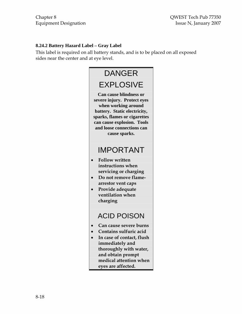
Chapter 8 QWEST Tech Pub 77350 Equipment Designation Issue N, January 2007
8.24.2 Battery Hazard Label – Gray Label This label is required on all battery stands, and is to be placed on all exposed sides near the center and at eye level.
DANGER EXPLOSIVE Can cause blindness or
severe injury. Protect eyes when working around
battery. Static electricity, sparks, flames or cigarettes can cause explosion. Tools and loose connections can
cause sparks.
IMPORTANT • Follow written
instructions when servicing or charging
• Do not remove flame-arrestor vent caps
• Provide adequate ventilation when charging
ACID POISON • Can cause severe burns • Contains sulfuric acid • In case of contact, flush
immediately and thoroughly with water, and obtain prompt medical attention when eyes are affected.
8-18

QWEST Tech Pub 77350 Chapter 8 Issue N, January 2007 Equipment Designation 8.24.3 BDFB Embargo Label These labels shall be placed at or near eye level near the AMP/VOLT meter on BDFBs .
As of ___/___/___ This BDFB has been
EMBARGOED for new growth due to load!
8.24.4 BDFB Maximum Feeder Drain Labels
The Maximum continuous drain on each feeder to this BDFB is 200 Amperes.
The Maximum continuous drain on each feeder to this BDFB is ___ Amperes.
8.24.5 High Voltage Caution Label
CAUTION: HIGH VOLTAGE
8-19

Chapter 8 QWEST Tech Pub 77350 Equipment Designation Issue N, January 2007
8.24.6 Power Restoral Procedure – Ericsson Products WARNING: Ericsson Switches
When a breaker Designated “PDF” is verified to be in the “off / tripped”
position do not reset until NROC (800-830-0722) has been contacted for assistance with Power Restoral
Procedures. Do not reset breakers / replace fuses designated “PDF” until all fuses have been removed from associated bus at
the “PDF” frame [AXE] – PDF [STP] – PDF
Contact NROC (800) 830-0722
8.24.7 Power Restore Procedure – Lucent Products
WARNING: Lucent Switches
When a breaker that is Designated “PCDF/PD/LPDU” is verified to be in the “off / tripped” position do not
reset until NROC (800-830-0722) has been contacted for assistance
with Power Restoration Procedures. Do not reset breakers / replace fuses designated “PCDF/PD”, etc. until all
fuses have been removed from associated bus at the “PDC” frame
[5ESS] – PDF (etc.) See: 235-105-220
Procedure: Chapter 14 Contact NROC (800) 830-0722
8-20

QWEST Tech Pub 77350 Chapter 8 Issue N, January 2007 Equipment Designation 8.24.8 Power Restore Procedure – Nortel Products
WARNING: Nortel Switch Products When a breaker Designated “PDC” is
verified to be “off / tripped”, do not reset until NROC (800 830-0722) has been contacted for assistance with Power
Restoration Procedures. Do not reset breakers / replace fuses
designated “PDC” until all fuses have been removed from associated bus at the
“PDC” frame [DMS 100/200/250/500]
See: NTP 297-8001-545 (Local Switches) or NTP 297-8021-545 (Tandem Switches)
Procedure: Chapter 2 [DMS 10]
See: NTP 297-3401-511 Procedure: EP 0006
8.25 Collocation Decommission Tag
8.24.9 Job Packet Storage Labels
8-21

Chapter 8 QWEST Tech Pub 77350 Equipment Designation Issue N, January 2007 8.26 Fire Code Power Room Door Placard
DC Power and Battery Room
This Room Contains
Energized Electrical Circuits and Lead-Acid Batteries
Battery Electrolyte is a Corrosive Solution
Protective Eyewear is Required (Additional Safety and Protective Equipment
for those working directly on the batteries is contained inside the room)
Warning: Battery Gases are Explosive
No Sparks or Open Flames Near Cell
8-22

QWEST Tech Pub 77350 Chapter 8 Issue N, January 2007 Equipment Designation 8.27 Alarm / OSS Testing Incompletion Tag (front and rear views are enlarged for illustration)
DOM RG 41- 0173
ALARM / OSS TESTING INCOMPLETION TAG Technician Responsibilities: (Test of alarms at shelf turn-up.) 1. Review the Central Office Job Packet for alarm details and requirements. 2. Contact NMA Database and TEST all required Alarms/OSS with them. X.25/IP: 763-536-2441 NMA Database Contact: _____________________ Phone #: __________________ Date:__________________
Serial/Discrete: 763-536-3888 NMA Database Contact:_____________________ Phone #:_____________ NMA Log #:_______________________ Issue Date:___________________ 3. When ALL alarms have been tested with NMA Database, complete this tag and store it in the Central Office Job Packet envelope for the associated BVAPP. 4. Alarm Type Tested: Test completion date:_____________________
Serial Discrete X.25 IP
(OVER)
ATTENTION: DO NOT REMOVE THIS TAG UNTIL ALL ALARMS HAVE BEEN TESTED WITH NMA DATABASE.
Installer to Complete this side of the Tag.
Each shelf of equipment that is CABLED to any e-telemetry unit (e.g., DANTEL), AI Switch, COLAN, or alarm device, and cannot be tested with NMA Database, shall have this tag attached to the front of the equipment shelf by the installer. If the installer performs a partial test of the alarms for the shelf, complete the appropriate section below, in addition to all other sections. NOTE: For all Serial or Discrete alarms, installer must call NMA Database for a Log Number, then populate the tag. BVAPP: ____________________ Date Tag Placed: ______________________ Relay Rack: _____________ Shelf No.: _______________ EQDES: ______________ Installation Company: ___________________ Non-Tested NMA Log #:___________ Installer Name: ___________________________ Phone: ______________________ If Partial Test was Done, Indicate Alarm Type Wired and Tested: Serial Discrete X.25 IP
NMA Database Contact:________________________ Phone #:______________ Tested NMA Log #:_______________________ Issue Date:_________________
Wired Alarm Type that Requires Testing: Serial Discrete X.25 IP
(OVER) 8-23

Chapter 8 QWEST Tech Pub 77350 Equipment Designation Issue N, January 2007 8.28 Lockout/Tag out Label (Enlarged for illustration - Refer also to Par. 9.1.12 and 9.7.1.1)
DANGER
EQUIPMENT LOCKED-OUT/ TAGGED-OUT
BY
NAME PHONE COMPANY DATE
8-24

Chapter 8 QWEST Tech Pub 77350 Equipment Designation Issue N, January 2007
8.29 Equipment “Removal from Service” Tag (Refer also to Par. 3.10.9)
RG 43-0007
DO NOT USE THIS EQUIPMENT
THIS EQUIPMENT HAS BEEN
REMOVED FROM THE CORPORATE RECORDS
THIS EQUIPMENT IS
SCHEDULED FOR REMOVAL
REFER ALL QUESTIONS TO: ENGINEER:____________________ TEL. NO.:______________________ BVAPP NO: BV_________________ DATE TAG PLACED: ____________
RG 43-0007 (06-04) 8.30 Building Column Designations
8.30.1 Building columns in Qwest central offices will be designated per guidelines established by the Qwest Real Estate organization. Refer to Par. 8.30.2. The stenciling effort will be performed by personnel contracted or approved by the Real Estate group specifically for this purpose and will not be the responsibility of installation services contractors or Qwest Technical Installation (QTI) personnel.
8.30.2 Column designations in existing locations and new building additions will be applied with input from the Qwest Common Systems Power (& Space) Environment and Central Office (CSPEC) and Design Engineering groups using Central Office Equipment Facility Management (COE-FM) as follows:
• All column designations will be consistent with the intent of the Planning and Design Engineer(s) responsible for that central office location. Column designations and COE-FM drawings shall match.
8-25

Chapter 8 QWEST Tech Pub 77350 Equipment Designation Issue N, January 2007
• The identification markings shall consist of a building column paint applied neatly to all applicable sides of the column (even columns embedded within walls). Due to peeling over time, P-Touch and other labeling methods are not the preferred method of designating columns.
• Column designation characters should be 4 inches in size and stenciled in black with a white background. They should be visible from the floor on all sides. They typically reside 6 feet from the finished floor.
8.31 Equipment “Hot Surface” Tag (Refer also to Par. 8.13)
CAUTION: HOT SURFACE
8.32 National Fire Protection Association “Very Early Warning Fire Detection Alarm System” Tag (Refer also to Par. 2.6 and Par. 15.10)
8-26

QWEST Tech Pub 77350 Chapter 9 Issue N, January 2007 Power
TOC 9-i
CONTENTS
Chapter and Section Page
9. Power ...............................................................................................................................9-1 9.1 AC Circuits......................................................................................................9-1 9.2 Primary & Secondary Distribution..............................................................9-7 9.3 Battery Primary Conductors.........................................................................9-9 9.4 Bus Bars ...........................................................................................................9-10 9.5 Cabinets ...........................................................................................................9-11 9.6 Connecting ......................................................................................................9-11 9.7 Fuse Bays, BDFBs, POWER BOARDs, etc. .................................................9-14 9.8 Fuse Contact Preparation and Protection...................................................9-15 9.9 Knife Switches, Fuses and Fuse Mountings...............................................9-15 9.10 Standby Engines.............................................................................................9-16 9.11 Wire Information Table..................................................................................9-19
Figures 9-1 Switch Distribution Voltage Drops .........................................................................9-17 9-2 Equipment Distribution Voltage Drops..................................................................9-17 9-3 Voltage Drops from Battery Strings to BDBs.........................................................9-18


QWEST Tech Pub 77350 Chapter 9 Issue N, January 2007 Power
9-1
9. Power
Reference: 1. Qwest Technical Publication 77385, “Power Equipment and Engineering Standards.”
2. The Architecture, Models, and Configurations (AMC) of some specific types of equipment and Qwest Drawing Standards may supersede some requirements identified in this chapter.
Notes:
• All connectors, wiring, conduit, fixtures, etc. installed in Qwest locations shall meet the requirements of the National Electric Code (NEC), National Electrical Manufacturer's Association (NEMA), Underwriters' Laboratories (UL), or Canadian Standards Association (CSA).
• Service Suppliers engaged in the installation, removal, or modification of live power equipment shall protect exposed live conductors, bus bars, adjacent equipment, etc. with power insulating blankets. Materials other than power insulating blankets shall not be used. Refer to cautionary notes in 2.4.8.
• No work shall be performed on LIVE AC Circuits by anyone other than a Qualified Electrician. Since most AC circuits and some DC circuits can be worked on with the energy removed, the MOP shall contain the reason for working on any live AC circuits. Work on live circuits shall not proceed without the specific approval of the authorized Qwest person. For AC circuits that can be de-energized, lock-out / tag-out procedures must be followed.
• The building location Single Line AC drawing shall be updated with any installation of major AC components. Identification shall be placed on added AC components to agree with the identification on the Single Line AC drawing. Major components are defined as panels, switchboards and other distribution equipment from which individual circuits are derived.
• The real estate document “Building Equipment Design Guidelines” for electric (division 16) shall also be adhered to.
• The removal of a fuse or the opening of a breaker for the purposes of de-energizing a DC circuit shall be done by a Qwest employee. Prior to de-energizing, a current probe or clamp on ammeter capable of reading DC current shall be used to identify zero current flow. Only one LOAD of current to any one element shall be de-energized at one time.
9.1 AC Circuits
Note: AC circuits serving an “Isolated” ground plane shall not be extended to serve an “Integrated” ground plane.

Chapter 9 QWEST Tech Pub 77350 Power Issue N, January 2007
9-2
9.1.1 Wire Type and Color
9.1.1.1 AC wire for distribution shall be THWN, THW, or THHN type.
9.1.1.2 Exposed ACEG conductors shall be green in color, or taped green where they are run exposed.
9.1.1.3 Green conductors shall not be used for any purpose other than an ACEG conductor, interior ring ground, or Central Office grounding conductors, unless the manufacturer has used it in intra-bay or intra-shelf wiring (which is not preferred)..
9.1.1.4 Neutral conductors shall be white or gray, or taped gray/white at all appearances.
9.1.1.5 Hot or phase conductors shall conform to the following color configurations:
Typical Power Wiring Color Code:
Nominal Voltage Phase/Line/Leg Color
240/120 L‐1
208/120 Y
240/120 Δ Ø‐A
Black
240/120 L‐2 Red 208/120 Y Ø‐B 240 Δ
208/120 Y Ø‐C Blue 240/120 Δ 240/208 Δ Ø‐B Orange 480/277 Y 480/277 Y Ø‐A Brown 480/277 Y Ø‐C Yellow
Grounding Green or
Green w/yellow stripe or bare Copper
9.1.2 AC Connecting Methods
9.1.2.1 Compression connections are preferred for AC termination.
9.1.2.2 Mechanical and single hole connectors are permitted where allowed by the National Electrical Code (NEC) and are readily accessible for inspection, repairs and

QWEST Tech Pub 77350 Chapter 9 Issue N, January 2007 Power
9-3
maintenance. They may not be used when the conductors terminate in vibrating machinery (generators, etc).
9.1.2.3 Connectors shall be the proper size specified by the manufacturer for the wire gauge and type, copper or tin-plated copper and the correct hole size for mounting hardware.
9.1.2.4 Connections of ACEG conductors shall not be made by wrapping the conductor under a mounting screw/bolt. A two-hole connector, ground bar or terminal strip shall be used. The exception is when connecting the ACEG to a common NEMA configuration outlet box, switch and/or receptacle.
9.1.3 Wire Nut Connections
9.1.3.1 Shall be placed so as to be accessible for maintenance and inspection.
9.1.3.2 Shall be made in an approved enclosure; i.e., junction box, conduit box, or pull box.
9.1.3.3 Splices shall not be made in the open areas of frame bases, vertical cable ducts, or end guards unless they are a raceway approved for splicing.
9.1.3.4 Shall be the correct size for the wire gauge and number of conductors being joined.
9.1.4 Enclosures, Cabinets, Boxes and Panels (Commercial and Emergency Service)
Protective metallic coverings (such as conduit, armor, lead covering, raceways, boxes, fittings, cabinets and fixtures) shall be grounded. Underwriters Laboratory (UL) approval of these coverings and devices assure that they will extend ground to one another when mechanical connections are made up tight. Ground is provided to the house service cabinet and ground continuity is extended to the power consuming device through these enclosures.
9.1.4.1 Qwest requires that a separate AC Equipment Ground conductor (ACEG) is extended in all raceways of all circuits.
9.1.4.2 The ACEG shall be enclosed in the same conduit or raceway with the phase and neutral conductors.
9.1.4.3 All enclosure covers, service panel covers or doors removed during installation shall be replaced at the end of each working day.
9.1.4.4 All AC enclosures, where knock outs or circuit breakers have been removed, shall be equipped with appropriate plugs, caps, or covers.
9.1.4.5. All unused, punched knockouts or holes in boxes and cabinets shall be closed. per NEC Article 110-12(A).
9.1.5 Conduit

Chapter 9 QWEST Tech Pub 77350 Power Issue N, January 2007
9-4
9.1.5.1 All wall mounted conduits shall be run per job drawing / record, securely fastened at a maximum interval of ten feet and within three feet of each outlet box, junction box, device box, cabinet, conduit body or other tubing (Refer to NEC 348.30, 370.4, etc.). Refer to the Qwest Technical Publication 77351 for conduit requirements within a typical toll environment.
9.1.5.2 Conduit shall be attached to the ceiling, suspended as close as possible and placed so as not to block future cabling, ladders, etc.
9.1.5.3 All rigid, Electrical Metallic Tubing (EMT), and liquid tight flexible metallic conduit runs shall be made with compression or threaded type fittings, couplings, and junction boxes. Set screw or stake type fittings and couplings shall not be used in Qwest locations on conduit sizes 1-1/4”and smaller. Exception: Screw type fittings and couplings may be used on armored cable and flexible metallic conduit, and on conduit larger than 1-1/4” diameter.
9.1.5.4 Poly Vinyl Chloride (PVC) conduit is not allowed for running AC circuits, alarm /monitoring leads, or other miscellaneous wiring applications.
9.1.5.5 Conduit, flex conduit, or armored cable may not be run in cable rack or on hangers with switchboard, fiber or power cable.
9.1.5.6 Metal flex conduit or armored cable shall not be run exposed for a distance exceeding three feet and shall never be used in a power room environment. Insulated coated armored cable or liquid tight flexible metallic conduit may be run in excess of three feet when properly supported. Liquid tight flexible metallic conduit shall never be run on a cable rack with switchboard or other power cable. These cables may be secured to auxiliary framing (but not cable rack stringers) using No. 9 cord. Armored cable and flexible conduit run outside of the power equipment application must be placed in accordance with TP 77351 Chapter 7B.6 and Section 4.2 on page 4-3, P. 8-8 (p. 8.4) and Sect. 1.3. Flexible MC cable is allowed to be used under raised floors (if the floor is used as a plenum; the flexible MC must be sealed.
Note: Liquid tight flexible metallic conduit should never be run in excessive lengths in applications where rigid, metallic EMT conduit should be used.
9.1.5.7 No wire splices are permitted within conduits. Make splices only in authorized boxes, fittings, wireways, etc. See 9.1.3, “Wire Nut Connections.”
9.1.5.8 Conduit shall, where possible, be run parallel and adjacent to auxiliary framing or cable rack.
9.1.5.9 All bends made to EMT or rigid conduits shall be made with a tool specifically designed for that purpose. The conduit bends shall not contain kinks or other imperfections.
9.1.6 Branch Circuits

QWEST Tech Pub 77350 Chapter 9 Issue N, January 2007 Power
9-5
Note: Use UL approved spring clips, wire nuts, solderless connectors, etc. to make AC branch circuit connections.
9.1.6.1 When adding branch circuits from the distribution panel or extending existing circuits, verify that no local continuity exists between the added neutral (white/gray wire) and the ACEG (green or bare wire) before the connection is made.
9.1.6.2 Lighting circuits and appliance outlet circuits shall not be supplied by the same branch circuit. However, conductors for both types of circuits may be run in the same conduit/raceway providing the conduit/raceway is properly sized for multiple circuits. Circuits from protected sources (i.e. inverters) are to be separately identified per NEC 200.6(D).
9.1.6.3 Lighting circuits supplied by polyphase service shall be assigned in such a manner as to balance the load on the different phases/legs as closely as possible. One neutral conductor of the same size as the phase conductor(s) shall be run with each phase conductor set.
9.1.6.4 All AC circuits shall have a separate ACEG (green wire) run with phase conductors.
9.1.7 Appliance and Utility Outlets
All outlets shall be of the standard type that connects its grounding terminal to its frame. Isolated ground or “Orange” outlets are not allowed going forward in QWEST locations.
9.1.7.1 Grounding and polarity verification of outlets is required.
9.1.7.2 When removals involve AC, as with appliance/base outlets, utility outlets, or permanently mounted power strips, all remaining AC conductors shall be properly terminated.
9.1.7.3 In Stored Program Control Systems (SPCS) switching equipment, the appliance outlets will be provided as an integral part of the SPCS. In no instance shall appliance outlets be added to any SPCS equipment without meeting all interface and grounding requirements of that SPCS equipment.
9.1.7.4 In non-switch areas or where standard configurations specify, appliance outlets for equipment frames shall be spaced approximately every six feet or every third frame, front and rear. When only one frame is installed initially in a line-up, an outlet shall be provided in that frame. Very small central offices, e.g.; CEV’s, huts and CDO’s, along with power distribution frames and BDFB’s are exempt from this requirement. Miscellaneous frames in the power room or power area that do not contain distribution or rectifiers are not exempt.
Note: In certain instances, a Letter of Deviation (Refer to Par. 2.11) may be granted to adjust the placement of outlets to approximately every ten feet or every fifth frame,

Chapter 9 QWEST Tech Pub 77350 Power Issue N, January 2007
9-6
(front and rear) for applications where fewer outlets may be required by Central Office Operations and/or CLEC customers.
9.1.7.5 Outlets shall have their ground terminal referenced to the frame in which they are mounted.
9.1.8 Multiwire Circuits
All multiwire (two or more ungrounded conductors) branch circuits shall be wired with a continuous grounded conductor (neutral), except for rectifiers fed by 208V or 240V single-phase ”…the continuity of a grounded conductor shall not be dependent upon device connections, such as lamp holders, receptacles, etc., where the removal of such device would interrupt the continuity.” [NEC 300.13(B)].
9.1.9 Flexible Cordage
9.1.9.1 Excess flexible cordage shall be bundled, secured, and stored in a manner that prevents accidental disconnection or snagging.
9.1.9.2 Flexible cordage shall not be used to extend “base outlet” AC supply to permanently mounted equipment. A dedicated circuit is required for this type of installation.
9.1.9.3 Exception: When temporary AC power is required to rewire or remove an existing dedicated circuit, GFCI-protected flexible cordage of the proper type and gauge may be temporarily used to supply power to permanently mounted equipment. (See 9.1 “AC Circuits.”)
9.1.10 Receptacles
Higher voltage receptacles shall have the receptacle cover plate marked with the appropriate voltage (e.g., 208V AC, 240V AC, 277V AC, etc.). Stamp with three sixteenths of an inch or equivalent font characters in vermilion (red) ink. Receptacles protected at over 20 amps shall have the protection size stamped as above.
9.1.11 Dedicated Circuits
Frame mounted equipment (modems, permanently mounted test equipment, etc.) that require AC utility outlets or power strips, shall have a dedicated circuit. This circuit shall be designated at both ends. Protected AC circuits (fed from an inverter or UPS) shall be utilized for this purpose if available in the central office. Dedicated AC circuits should be in a separate conduit from the equipment to the AC source. Where this is not possible, such as limited surface opening space on the panel or only gutter access to the panel is provided, this circuit can share the same conduit or gutter with existing outlet circuits if all NEC code requirements (conductor fill, etc.) are met. A dedicated circuit that is in a shared enclosure, junction, or pull box shall be designated at each enclosure, junction, or pull box.

QWEST Tech Pub 77350 Chapter 9 Issue N, January 2007 Power
9-7
9.1.12 Work Performed On Live Circuits - Lock Out/Tag Out
All persons that intend to work on or around energized circuits or circuits that could become energized shall be familiar with and adhere to the Qwest practices described in the safety and loss prevention manual that applies to lockout / tagout. This practice is consistent with OSHA requirements. Refer also to Par. 8.28 and 9.7.1.1.
9.1.13 Temporary AC Circuits
When work requirements dictate the necessity to power permanently mounted equipment with temporary AC power, flexible cordage, such as type SJ00-junior hard service cord, may be used. However, suitable disconnecting switches at plug connectors shall be installed to permit the disconnection of all conductors of each temporary circuit simultaneously (NEC 305-3). For Qwest purposes, temporary AC power refers to any wiring configuration installed to supply AC power that will be disassembled and removed prior to the actual completion of a job and includes extension cords. All such circuits shall be Ground Fault Interrupter (GFI) type and run in a manner that properly supports and protects the temporary circuit and personnel and does not present a safety hazard.
9.1.14 Frame and Aisle Lighting
Frame and aisle lighting shall conform to standard design configuration, or follow approved existing office convention. The Service Supplier shall follow the switch manufacturer’s requirements as determined by the job site situation.
9.1.15 The operating temperature of all AC and DC wiring in UPS equipment will not be greater than 20°F above the ambient temperature, or 115 degrees Fahrenheit, whichever is higher.
9.1.16 High Temperature Surfaces
9.1.16.1 Exposed surfaces with temperatures that can be greater than 115° Fahrenheit shall be marked with warning labels.
9.1.16.2 Surfaces that can reach temperatures greater than 130° Fahrenheit shall be guarded as well as marked with warning labels.
9.2 Primary & Secondary Distribution
9.2.1 Run all leads in continuous lengths per job specification. The use of “in-line” drop splices or H-tap connections does constitute “continuous length” runs. Installation work at a Power Board or BDFB shall be completed before the total job has reached 70% complete.
9.2.2 DC wire for distribution and grounding shall be RHW, or XHHW (in standard Class B stranding or flexible Class I stranding) halogenated or non-halogenated wire. This requirement applies to all DC power conductors that are 14 AWG and larger. The color of –48V & RTN (DC) power leads is typically gray (with a blue tracer for non-halogenated RHW without a cotton braid cover) or black (with a red tracer for non-

Chapter 9 QWEST Tech Pub 77350 Power Issue N, January 2007
9-8
halogenated RHW without a cotton braid cover). Grounding conductors shall be green (and can be made with a yellow tracer, which is required, for non-halogenated RHW without a cotton braid cover) or bare.
Note: All XHHW wire does not require a cotton braid or to be fiber-wrapped (due to “cold flow”) at lacing points on cable rack straps. Also, it is not required that this cable be tinned when it is run outside the power room, since there are no halogenic or sulfuric compounds to oxidize and corrode the copper. Unfused power leads must be tinned.
9.2.3 All battery and battery return cables shall be run closely coupled and in pairs (except for at the termination ends, and for return conductors running past remote ground windows, which must be paired back on themselves). Power cables (Battery and Battery Return) run on panned racks shall be paired and secured together at 24-inch intervals. (“Paired” is defined as placing these cables above/below or at the side of each other and securing with a No. 9 cord lock stitch such as would be done when sewing on power cable rack with existing conductors.)
9.2.4 Where space does not permit the addition of a separate, dedicated power cable rack, power cables protected with 70 amp or less fuses / breakers may be run on cable racks utilized for switchboard cabling if they are sized at No. 4/0 AWG or smaller. All power cables larger than No. 4/0 AWG regardless of fuse / breaker size shall be run on dedicated FUSED POWER CABLE ONLY cable racks (TP 77385). The placement of any type of cable used for anything other than power on FUSED POWER CABLE ONLY racks is strictly prohibited. The issuance of Letters of Deviation waiving any of these requirements in a central office going forward shall be considered invalid. Also refer to Chapter 5, Par. 5.6.
9.2.5 Primary DC power distribution cable shall be run on a dedicated DC power cable rack. Primary DC power distribution is defined as leads from the power plant to the BDFB or the power distribution frame dedicated to a switch. Secondary DC power distribution is defined as power from the BDFB to the equipment. Primary and secondary power leads are not to be segregated and can be run commingled on the same dedicated power cable rack.
9.2.6 When secondary power cable is tapped down for entry into equipment frames, taps shall be placed on the cable rack between cable rack straps, and staggered above or within six feet of either side of the frame, bay, or cabinet.
9.2.7 All tap connections shall be accessible for inspection. Connections that are taped and have covers applied shall be considered accessible. Heat shrinkable tubing, other than clear, is not considered accessible.
9.2.8 Main conductors and feeders in the plant should be sized for the ultimate capacity of the plant (see TP 77385).
9.2.9 Unfused cables from chargers to batteries and from batteries to discharge panels or bus assemblies shall be on a separate cable rack from all other cables. Power conductors that run from the battery string to the power board are considered “unfused leads.”

QWEST Tech Pub 77350 Chapter 9 Issue N, January 2007 Power
9-9
Note: In power rooms untinned wire will not be used in applications where “unfused leads” are required. Cabling in those applications must be tinned and is usually rated by the manufacturer as “Class I flex” power cable. However, untinned wire can be run in the power room for –48V distribution from the power board to any subsequent distribution location. In that application(s) the installer is required to “dead-end” these “hot” power leads on the cable rack above the power board and H-tap down the associated Class I flex “drops” that terminate directly to the power board. The return conductors do not generally tap down, but are run directly to the return buss bar assembly.
9.3 Battery Primary Conductors
Battery distribution circuits protected at 100 AMPs or greater may require a means to monitor the load. Refer also to TP 77385.
9.3.1 On new installations of primary DC (unfused) power cable in a central office, the cable shall not share a cable rack with any other type cable and shall be run on dedicated DC power cable rack.
9.3.2 All battery and battery return cables shall be run closely coupled and in pairs. with the following exceptions:
9.3.2.1 This "pairing" requirement does not apply to cabling between the power plant and batteries and/or primary distribution board, or the cable within a few feet of the return bus of a secondary distribution center — e.g. BDFB.
9.3.2.2 It also is not required for Outside Plant applications — cabinets and Customer Premise — where the DC plant size does not exceed 100 Amperes.)
9.3.2.3 In cases of a remote ground window where the served equipment is not on the same floor as the remote ground window the battery feed leads do not have to be paired with the battery return leads all the way to the ground window. For the portion of the run where the battery feed and the battery return leads are not paired, the battery return lead shall be paired back on itself, (this includes going through the same cable hole). The total impedance of the battery feed and the total impedance of the battery return must be equal (i.e., the voltage drop must be divided equally between the battery feed and the battery return — 0.5 V one-way drop for both the feed and return). Refer to Qwest Pub 77355 for ground window guidelines as required.
9.3.2.4 Between the bays and/or battery stands, internal to the power plant, paired battery and return are preferred. However, unpaired leads are allowed internal to the power plant under the following conditions:
- They are run as closely as possible;
- No other cables are placed between them; and
- No non-referenced (ungrounded) equipment is within ten (10) feet.

Chapter 9 QWEST Tech Pub 77350 Power Issue N, January 2007
9-10
9.3.2.5 The battery return leads are not to be confused with the grounding conductors and are exempt from the green color requirement. They are not to be marked or otherwise identified with the color green. Nor should they be colored red unless that is the color from the manufacturer in a winning harness.
9.3.2.6 Occasionally it is required to run DC conductors inside of a conduit. When this is required, both the battery and battery return shall be paired in the same conduit.
9.4 Bus Bars
9.4.1 Bus bars shall be free of sharp edges, burrs, corrosion, etc. and shall be copper or tin-plated copper.
9.4.2 Bus bars shall be properly supported per drawings/records and insulated from surrounding metal work.
9.4.3 Coating and Plating
A metallic coating or plating is sometimes used on bus bars to reduce the resistance of the connecting joints. These contact surfaces should be cleaned with a clean, dry cloth to remove grease and other foreign matter, but should not be sanded or the surface otherwise scratched. Non-plated copper bars shall have connection points cleaned. See 9.4.6, “Bolts, Screws, Nuts and Washers,” and Section 9.6,“Connecting.”
9.4.4 Aluminum Bus Bars
9.4.4.1 Aluminum bus bars are not authorized for new installation. Where aluminum bars exist, contact the QWEST Design Engineer for approved connecting procedures.
9.4.4.2 Existing aluminum bus bars shall not be tapped for fastening terminal lugs or for fastening bar to bar. Use through bolts, clamp joints or threaded inserts.
9.4.5 Bus Bar Clamps
Install a pal nut or locknut on each bus bar clamp bolt. Verify that regular nuts are tight before applying the pal nuts or locknuts.
9.4.6 Bolts, Screws, Nuts and Washers
Ferrous bolts, screws, nuts, washers, bus bar supports and clips used in fastening copper to copper, or combinations of metals shall be zinc or cadmium plated; however, copper, copper plated, tin-plated copper and stainless steel parts may be used when furnished.
9.4.7 Protective Enclosures
Bus bars which are located external to an equipment framework enclosure, and have a potential different than the surrounding or supporting metal work shall be protected from short circuits by means of an insulated removable cover. The intent of this requirement is to prohibit the practice of using tape as the protecting medium on bus

QWEST Tech Pub 77350 Chapter 9 Issue N, January 2007 Power
9-11
bars and to allow protection to be removed and reinstalled for growth and/or maintenance activities.
9.4.7.1 Bus bars requiring protective covers:
• All battery bus bars and splice plates not located within the power room or within a framework enclosure.
• Battery return splice plates where the potential of the plates are associated with an isolated ground plane, but are physically located and/or supported from ironwork associated with the integrated ground plane.
9.4.8 Bus bars that do not require protective covers:
9.4.8.1 All bus bars or splice plates located on a battery stand or in a power room, unless they present a safety or service hazard.
9.4.8.2 Battery return distribution bars located above a BDFB. Even if the power source feeding the BDFB is used to power a SPCS, the BDFB should appear subsequent to the Ground Window; therefore, contact between the return bus bar and surrounding metalwork would not constitute a single point ground violation.
9.4.8.3 Bus bars used as the Main Grounding Bar (MGB). This is the point of interface between the two ground planes (commonly referred to as the Ground Window). Therefore, accidental and / or additional contact with either ground member would have minimal effect.
9.4.8.4 Bus bars that are used as a grouping point to bond integrated ground members together or to the MGB when required.
9.4.8.5 Central Office (COGB), Principal Ground Point (PGP) and Office Principle Ground Point (OPGP) bars.
9.4.9 Separation of Bus Bars from Surrounding Objects
9.4.9.1 All Bus Bars shall be a minimum of 3 inches from any metal objects. Where this cannot be avoided, insulation must be provided between the Bus Bar and the metallic object. All Bus Bars shall be installed as to afford ready access.
9.4.9.2 All Bus Bars shall be installed as to afford ready access to the connecting surface (minimum of 4 inches of clearance).
9.5 Cabinets
Isolated cabinets such as motor starters, self-contained power distribution service cabinets, generator control bays, etc., shall be secured to the floor with a minimum of four approved 12mm, torque indicating, expansion anchors. See Paragraph 3.21,”Floor Anchors and Installation Instructions.”
9.6 Connecting
Electrical resistance shall be kept as low as practical.
Chapter 9 QWEST Tech Pub 77350 Power Issue N, January 2007
9-12
9.6.1 Contact surfaces shall be cleaned so that direct metal to metal contact is made. Non conductive coatings (such as paint, lacquer and enamel) on equipment shall be completely removed under the entire contact surface to assure good electrical continuity. Copper bars may require the use of low abrasive pads to remove oxidation.
9.6.2 Plated surfaces, such as silver or lead plated copper, etc., are plated to prevent oxidation and reduce contact resistance and, therefore, should never be sanded or abraded. If cleaning is required, wipe with a dry cloth.
9.6.3 Mating surfaces shall be flat to ensure maximum cross-sectional area contact.
9.6.4 A non-oxidizing agent shall be applied to inhibit corrosion on all battery, battery return, and grounding connections, ie. at all contact points, bolts, washers, nuts, "H" taps, "C" taps, lugs and other items. This non-oxidizing agent is an insulator, so only a thin coat should be applied.
9.6.5 Pressure or clamping devices shall be tight.
9.6.6 DC power, return, and bonding/grounding lead connections shall have lock washers installed to ensure secure connections. Use shake proof (star) lock washers under mounting screws and split ring lock washers with bolts and nuts, except where double or locking nuts are standard. Lock washers shall not be placed between the connecting terminal and the contact surface. Connections that require annual re-torquing routines do not meet Qwest Standards and are not acceptable. Battery inter-cell connectors are exempt from this requirement since they require annual retorquing. For those kits that are not equipped with lockwashers (Refer to Par. 10.2.12.2).
9.6.7 General Connecting Methods
Attach only one lead to a punching, lug or connector that is designed to accommodate one lead.
9.6.7.1 Attach only one connector with the same mounting screw(s) or bolt(s) unless specified in the associated equipment AMC configuration. Frame ground connectors, chassis, shield, and equipment bonds shall not be stacked one on top of the other under the same mounting hardware.
9.6.7.2 Any connector drilled with two holes shall be secured using both holes.
9.6.7.3 On BDFB and Power Boards all alarm wiring for power fuses and associated alarm fuses shall be connected initially whether the locations are to be fused or to be made spare.
9.6.7.4 Stranded cables shall retain all of their strands at the point of termination.
9.6.7.5 All connectors with a potential other than ground shall be protected if they extend out beyond a protective cover and if they are within 3 inches of any differing potential. Suitable protection shall be clear heat shrinkable tubing or one wrap of sheet fiber paper.
9.6.8 Crimp/Compression Connections

QWEST Tech Pub 77350 Chapter 9 Issue N, January 2007 Power
9-13
DC power connections for supply and return shall use irreversible crimp-type copper connections, wire wraps, or latching "plugs". Aluminum connectors shall not be used, and set-screw connections are not allowed. DC power connections to non service-affecting equipment (e.g., indicating lights, alarm equipment) are exempt from this requirement.
9.6.8.1 Internal to the supplier's equipment, power connections types are the prerogative of the equipment manufacturer.
9.6.8.2 DC power connections between the source fuse panel and the shelf shall meet the requirements of Par. 9.6.8 above (e.g.; can be a one-hole or two-hole crimp, wire wrapped, or latching “plug”) depending on equipment design.
9.6.8.3 All connections to a battery return bus bar must be a two-hole crimp only. These connections should be stacked (one above and one below the return bus bar) to conserve space. Exceptions to the “two-hole” requirement are allowed for battery return bus bars in DC plants rated at 50 Amperes or less.
9.6.8.4 All connections (nuts and bolts) made to battery posts, terminal plates, and inter cell connectors shall be made with stainless steel (preferred), lead, or lead-coated copper. Lead-plated compression-type lugs are not required to have inspection holes. However all other compression type lugs are required to have inspection holes.
9.6.8.5 On flooded batteries, inter-cell connectors, inter-tier connectors, inter-row connectors, terminal plates, and all connector lugs connected directly to the battery posts shall be lead or lead-coated copper. There shall be NO exceptions to this. Tin-plated copper compression type lugs can be used when connecting to the terminal plates, however they cannot be used to connect directly to the battery posts. There will be no connectors varnished, lacquered or painted, during or after installation.
9.6.8.6 For battery connectors, heat shrink tubing will only be applied at the factory during initial manufacture. Heat shrink tubing that does not provide a hermetically sealed connection will not be allowed. Only clear heat shrink tubing may be used.
The integrity/quality of a crimp connection is dependent upon the following:
9.6.8.7 The correct size connector for the particular wire size(s) involved.
9.6.8.8 Insulation removed so that the wire extends the full length of the barrel or groove.
9.6.8.9 Preparation of the wire end and connector as required.
9.6.8.10 The use of a non-oxidizing agent on the wire and in the connector as required.
9.6.8.11 Full insertion of the wire into the connector. The wire shall be inserted to within 1/8 inch of the inspection hole for wire sizes No. 2 AWG and smaller and within 1/4 inch for wire sizes No. 1/0 AWG and larger.
9.6.8.12 Compress the connector the correct amount and in the proper sequence using the lug manufacturer's recommended tool and die set.

Chapter 9 QWEST Tech Pub 77350 Power Issue N, January 2007
9-14
9.6.9 Power/Grounding Connections
9.6.9.1 Mechanical connectors shall not be used in DC power distribution and grounding systems. Exceptions to this requirement are detailed in Qwest Standard Configuration documents.
9.6.9.2 All electrical connections shall be smooth and treated with a non-oxidizing agent.
9.6.9.3 Parallel taps for branching or frame entry on power and grounding conductors shall be equal to or smaller than the feeder conductor being tapped.
9.6.9.4 Battery and battery return connections made with H-taps require the connection to be taped, a cover applied, and secured with No. 9 cord.
9.7 Fuse Bays, BDFBs, POWER BOARDs, etc.
9.7.1 All fuses and circuit breakers shall be of the proper type and capacity specified in job drawings/records and shall be in compliance with manufacturers' design specifications. Cable ampacity shall equal or exceed the protecting device size. When manufacturers specify multiple loads (A&B, etc.) they shall be fused from different power board feeders. Fuses shall be installed or breakers turned on at the completion of the job to identify the correct polarity of the connection at the fuse panel, and test records shall be provided.
9.7.1.1 Lock Out/Tag Out warning labels shall be used on all DC circuits that are connected to the distribution source and are not energized at the time of termination. Refer also to Par. 8.27 and 9.1.12.
9.7.2 All cartridge, knife type fuses, and fuse reducers being installed shall be cleaned and lubricated with a non-oxidizing agent.
9.7.3 A non-oxidizing agent shall be applied to inhibit corrosion on all battery, battery return, and grounding connections.
9.7.4 Dummy fuses shall be installed where fuse holders depend on the dummy fuse as tensioning agents. Dummy fuses are no longer required at all unassigned fuse locations.
9.7.5 Alarm fuses shall be installed or an alternate system provided to indicate when a feeder fuse has opened. All BDFBs and PBDs that use TPS distribution fusing must use alarm fuses rated .18A (GMT-type).
9.7.6 Fuse reducers shall not be used in “dead front” fuse panels. Dead front is defined as having no exposed electrical potential. Fuse reducers shall not be used to reduce the fuse size more than once (double reducers).
9.7.7 All unassigned circuit fuses, their designations/pins, and associated alarm fuses shall be removed. Dedicated alarm fuse designation pins may remain in place. See Chapter 8 “Breakers, Fuses, Switches, and Shunts.”

QWEST Tech Pub 77350 Chapter 9 Issue N, January 2007 Power
9-15
9.7.8 All “live front” power distribution bays designed to have front protective covers, shall have those covers installed. Live front is defined as having exposed electrical potential.
9.7.9 All unequipped fuse/breaker block positions or panels shall have blank panels installed,. No holes shall be permitted.
9.7.10 The largest fuse permitted in a BDFB is 100 Amps, and only if the BDFB will accept that size of fuse (in some cases, use of these larger fuses may require sparing of the next and/or previous position due to heat per the manufacturer requirements).
9.7.11 No cable larger than a No. 2 1/0 AWG shall be terminated to a BDFB fuse position. Larger distribution cables shall be tapped down to a maximum of a No. 1/0 AWG before entering the BDFB. For miscellaneous-mounted fuse panels in relay racks, no cable larger than a No. 4 AWG shall be terminated on the rear entry of the panel (unless the source amperage and/or manufacturer’s specifications warrants a larger size).
9.7.12 BDFB fuse positions shall be cabled, installed and assigned from the bottom up in top-fed BDFB’s. Once installed, the fuse positions are numbered from the top down per TP 77385 Issue H; Fig. 8-7.
9.7.13 When power cables are tapped down in size for entry (see 9.7 “Fuse Bays, BDFBs, POWER BOARDs, etc.”), taps shall be placed within six feet of the entry point into the BDFB (15’ for PBDs). Taps shall be staggered to prevent pileups (reducing splices do not have to be staggered).
9.7.14 All tap connections shall be accessible for inspection. Connections that are taped and have covers applied shall be considered to be accessible. Heat shrinkable tubing, other than clear, is not considered to be accessible.
9.7.15 Equipment shall not be powered from BDFBs not located on the same floor or from BDFB’s supplied by different power plants.
9.7.16 Equipment loads on a BDFB feeder, shall never exceed 50% of their fused value.
9.7.17 Use only DC type fuses and breakers for DC circuits, and only AC type fuses and breakers for AC circuits.
9.7.18 No circuits shall be energized without both ends of the circuit identified and connected.
9.7.19 When 500V-rated insulation (minimum) is not used on conductive members of differing potentials, those conductors must be separated by at least 2 inches of air space (Refer also to Par. 11.5.1.1 and TP 77355).
9.8 Fuse Contact Preparation and Protection
9.8.1 Fuse ferrules, blades, and contact area of their associated clips shall be coated with a thin film of a non-oxidizing agent.

Chapter 9 QWEST Tech Pub 77350 Power Issue N, January 2007
9-16
9.9 Knife Switches, Fuses and Fuse Mountings
Power shall be disconnected whenever possible from switches, fuses, clips or connections before they are worked on. If the potential cannot be removed, protect adjacent parts of opposite polarity with insulating materials.
9.10 Standby Engines
9.10.1 The Qwest Design Engineer shall specify, prior to the start of installation, the electrical, intake, exhaust, fuel, and floor grade requirements based on the engine manufacturer's recommendations for the particular engine being installed.
9.10.2 Fuel systems shall be free of copper or galvanized metal.
9.10.3 Engine areas shall be labeled to provide warnings of hazardous conditions, as follows:
9.10.3.1 Noise: “Ear Protection Required” on or at Entrance and Exit doors.
9.10.3.2 Voltage: “Danger High Voltage.” AC Service Panels, Transfer Switch, Distribution Panel, Served Equipment (rectifiers etc.).
9.10.3.3 Fuel: “Danger NO SMOKING or Open Flame“ on or at Engine room and fuel storage systems and cabinets.
9.10.3.4 Temperature: “Danger HOT” on or at Engine exhaust system.
9.10.4 New standby engine-alternator installations and modifications to existing ones shall comply with TP 77385 and all current Standard Configurations. This includes “temporary” installations of any kind. All onsite testing, including connections to the site systems, shall have an authorized Qwest representative in attendance. The MOP for the job shall reflect the date for the work to start, to complete and include reference to having a Qwest person on site.
9.10.5 Cutovers/Turn-ups shall not occur unless all alarms are connected and tested.

QWEST Tech Pub 77350 Chapter 9 Issue N, January 2007 Power
9-17
Pwr.Board PD F S w i t c h
1.0 V M fg . 1.0 V
Chargers Battery Strings
< 2 Volts
0.45 V includes shunt
Figure 9-1: Switch Distribution Voltage Drops Loops
Pw r.Board E q p t .
1.0 V
BD F B
0 . 2 5 V
Chargers Battery Strings
< 2 Volts
0.45 V includes shunt
Figure 9-2: Equipment Distribution Voltage Drops Loop

Chapter 9 QWEST Tech Pub 77350 Power Issue N, January 2007
9-18
BDFB orPDFMain
ChandelierMain Power
BoardBusbars aboveBattery Stands
1.25 V Loop
1.0 V LOOP
0.20 V Loop
0.10 one way +0.05 for Shunt
Batteries
Sized perPar. 8.2
1.65 V Loop to any Battery Busbar
Figure 9-3: Voltage Drops from Battery Strings to BDBs

QWEST Tech Pub 77350 Chapter 9 Issue N, January 2007 Power
9-19
9.11 Wire Information Table
The cable is sized by the Design Engineer for ampacity and voltage drop. The Service Supplier is responsible for verifying that the circuit protection device is sized correctly for the cable.
WIRE INFORMATION
CIRCULAR WEIGHT DIA. OVER BEND
WIRE SIZE AMPS* MILLS PER FT INSULATION RADIUS
14 AWG 15 4,110 0.026# 0.19" 1.71"
12 AWG 20 6,530 0.035# 0.21" 1.89"
10 AWG 30 10,380 0.049# 0.24" 2.16"
8 AWG 40 16,510 0.084# 0.31" 2.79"
6 AWG 55 26,240 0.126# 0.40" 3.60"
4 AWG 70 41,740 0.190# 0.45" 4.05"
2 AWG 95 66,360 0.275# 0.51" 4.59"
1/0 150 105,600 0.443# 0.63" 5.67"
2/0 175 133,100 0.540# 0.68" 6.12"
4/0 230 211,600 0.814# 0.75" 6.75"
350 KCM 310 350,000 1.310# 0.98" 8.82"
500 KCM 380 500,000 1.815# 1.12" 10.08"
750 KCM 475 750,000 2.700# 1.34" 12.06"
1/0 FLEX 150 111,100 0.510# 0.66" 5.94"
2/0 FLEX 175 131,300 0.630# 0.72" 6.48"
4/0 FLEX 230 222,200 0.890# 0.84" 7.56" 350 KCM FLEX 310 373,700 1.490# 1.07" 9.63" 350 KCM FLEX 380 535,300 2.000# 1.24" 11.16" 350 KCM FLEX 475 777,700 2.900# 1.54" 13.86"

QWEST Tech Pub 77350 Chapter 10 Issue N, January 2007 Storage Batteries
TOC 10-i
CONTENTS
Chapter and Section Page
10. Storage Batteries......................................................................................................10-1 10.1 Cautions........................................................................................................10-1 10.2 General Requirements and Procedures ...................................................10-1 10.3 Initial Battery Charge Procedures for Flooded Cells .............................10-4 10.4 Flooded Lead Acid Type Battery Charging ............................................10-5 10.5 Initial Charge and Turnover Requirements for Flooded Cells.............10-6 10.6 Initial Charge Procedures for Valve Regulated Lead Acid Cells.........10-7 10.7 Charge Procedures for Valve Regulated Lead Acid Cells Stored for Reuse Applications ...............................................................................10-8 10.8 Electrolyte Spills..........................................................................................10-8 10.9 Installation/Removal Requirements for Lithium-based Batteries ......10-8 10.10 Installation Requirements for Nickel-based Batteries ...........................10-9


QWEST Tech Pub 77350 Chapter 10 Issue N, January 2007 Storage Batteries
10-1
10. Storage Batteries
See Qwest Technical Publication 77385, “Power Equipment and Engineering Standards.”
10.1 Cautions
10.1.1 Battery gases, which are present during a charge or which remain near the cell at the completion of a charge, can exist in sufficient concentration to explode. The Service Supplier shall ensure that sufficient ventilation is provided. The Service Supplier shall post, in a conspicuous location(s) near the batteries, one or more warning signs, lettered in large vermilion/red characters as follows:
***WARNING*** Battery gases are explosive.
No sparks or open flame near cells. 10.1.2 Flame arrestors shall be in place at all times except for as stated in 10.1.7. All flame arrestors shall be equipped with dust covers and remain in place at all times. If they are removed to allow access to the electrolyte, they must be replaced upon completion of the work operation. Cells equipped with thermometers shall have the dust cover drilled to accommodate the installation of the thermometer.
10.1.3 Prior to working on a battery cell, discharge static from yourself and any object before touching the cell. Static can be discharged by touching a grounded surface.
10.1.4 After the end of initial or boost charge, the battery must be on float or open circuit for more than 48 hours before any cell connections can be made. The same applies to work near the cells, (other than voltage readings) and to the use of open flames near the cells (which are never allowed).
10.1.5 For personal protection and protection of clothing, use chemical safety goggles, rubber gloves, coveralls and/or aprons as required.
10.1.6 Do not lift cells by means of intercell connectors or cell posts.
10.1.7 Flooded batteries shall not be sealed air tight for transportation or for any other reason, the manufacturer’s shipping caps/detail should be used to allow gas buildup to escape.
10.2 General Requirements and Procedures
Note: Manufacturer’s requirements and procedures shall be followed for all installations of batteries.
NOTE: An authorized Qwest representative shall be present during the following, or the installation cannot proceed:
1) Delivery of flooded cells to the site.
2) Start and end of initial charging.
Chapter 10 QWEST Tech Pub 77350 Storage Batteries Issue N, January 2007
10-2
3) Connecting or disconnecting string(s) at the bus bar(s).
4) Connecting or disconnecting cell(s) in string(s) that are connected to the plant. 10.2.1 The installer shall insure that the following items are on site and accessible prior to the start of any work involving batteries:
• Goggles or Face Shields
• Nitrile Rubber Gloves
• Rubber Apron
• Eye Wash Kit
• Spill Cleanup Kit*
*The Service Supplier is required to furnish and use their spill kits. See “Chapter 12”, “Central Office Equipment Removals and Installs; and the Proper Handling of Hazardous Materials” and/or the Qwest Environmental Manager in your area for required contents of spill kits.
10.2.2 When permanently installing new or reused batteries, cells from different manufacturers shall not be placed in the same string (with the exception that LCT-1680. cells may be used in place of discontinued TCC-1680 cells, and KS-spec cells of the same spec and list number may be used in the same string). Batteries of different manufacturers may, however, be placed in parallel; i.e., String A, String B, etc.
10.2.3 When replacing cells in a string, the replacing cells shall have the same ampere-hour capacity (with the exception of L-15 round cells which are allowed to be used with L-1 round cells even though the Ampere/Hour capacity is slightly different), the same number of plates, and shall be of the same technology.
10.2.4 Clean battery case with distilled or deionizaed water only. Clean and neutralize battery posts using a mixture containing bicarbonate of sodium (one pound/gal. of distilled/deionized water).
10.2.5 Petroleum-based lubricants for moving batteries are prohibited. The only approved product(s) are water-based lubricants or products specifically listed in the battery manufacturer’s manual..
10.2.6 Flooded Lead Acid cells may be tipped as much as 15 degrees, for periods not to exceed 20 minutes, in order to get through windows or past other obstructions, provided the vented shipping plugs are in place. All other cells containing electrolyte shall not be tipped to a point that their electrolyte leaks from cell.
10.2.7 All moving / installation within the Qwest building or sites shall be done by the installation service supplier company.
10.2.8 Distilled or de-ionized water shall be used to replenish the cells.
10.2.9 Battery Storage Report

QWEST Tech Pub 77350 Chapter 10 Issue N, January 2007 Storage Batteries
10-3
10.2.9.1 Storage Battery Report, Form RG 47-0001 shall be maintained on each battery throughout the installation and charging phases for battery installations.
10.2.9.2 Completed battery report(s) shall be turned over to the Qwest representative at the completion of the job. A copy of these records shall be left in the job packet and a copy retained with the battery string at the job site. The Service Supplier and Design Engineer shall ensure that a representative of Qwest NROC (Power Maintenance Engineer) or COO (Power Technician) reviews the battery report.
10.2.10 Temperature Reference Cell(s) (TR)
10.2.10.1 One cell in each newly installed flooded string shall be chosen as the TR cell. It shall be the cell on the upper tier with the lowest voltage reading at the end of the initial charge. It shall be recorded in the battery report forms. The TR cell shall not be a cell on the end of a battery string.
10.2.10.2 Remove shipping compound from all contact surfaces and apply a thin coating of non-oxidizing agent as specified by the manufacturer before installation.
10.2.10.3 Temperature variation across a battery string shall not exceed 5 degrees Fahrenheit. Recommended temperature is 77 degrees Fahrenheit. Facilities that fail to meet this standard need consideration in adjusting float voltage and calculation of battery reserve time. Contact the Power Design Engineer or NROC Power Maintenance Engineer.
10.2.11 Inter-cell Connections
10.2.11.1 The rounded side of the stainless steel washers shall be placed against the surface of the lead-plated straps to prevent cut through of the lead plating. See Chapter 7, “Connecting.”
10.2.11.2 Bolts on battery straps shall be installed (hex nuts positioned outward) to allow torque wrench access in meeting the battery manufacturer’s torquing requirements. When these requirements are met, the Service Supplier shall mark these bolts as “torqued” by using a black indelible pen to make a mark across the nut and bolt.
10.2.11.3 Lead bolts shall not be used.
10.2.11.4 Inter-cell cables shall be of equal length and shall not extend into an aisle way in such a manner as to be subject to damage.
10.2.12 Inter-tier connections
10.2.12.1 Cables shall be routed so as not to place undo strain on battery posts. 180 degree sharp bends are not permitted.
10.2.12.2 Cables shall be of equal length.
10.2.12.3 Cables shall be secured to the battery stand at a minimum of one location.

Chapter 10 QWEST Tech Pub 77350 Storage Batteries Issue N, January 2007
10-4
10.3 Initial Battery Charge Procedures for Flooded Cells
Note: The manufacturers’ requirements and procedures shall be followed for all charging of flooded cells.
10.3.1 An initial charge shall be given to all flooded lead-acid cells prior to turnover to Qwest (except for engine-start batteries). Verify that shipping plugs are removed and flame arrestors and dust covers are in place before charging cells.
10.3.2 A portable battery charger and protective fuse box should be used for charging batteries. In the event a portable charger is not available, then a job site rectifier (if readily available) can be used.
10.3.3 The charge voltage maximum limit is between 2.38 and 2.50 volts per cell average; and the battery manufacturer’s charging rates, voltages, times, and limits should generally be used.
10.3.4 In order to ensure the proper battery charging, the charging device shall be at least 1/100th of the battery Ampere-hour rating. Example: 4000 amp hour batteries would require a minimum of a 40 amp charger per string.
10.3.5 Immediately prior to the start of initial charge, measure the cell temperature of each cell and determine the total length of initial charge requirement by referring to the manufacturers' specification. If no manufacturer recommendation can be found, refer to the corresponding cell temperature column and time on open circuit column from 10.4 “Flooded Lead Acid Type Battery Charging”.
10.3.6 While on initial charge, the electrolyte level may rise above the maximum level line. If it does, do not be alarmed. The electrolyte level in rectangular cells is preadjusted by the manufacturer to be between the level lines when the cells are floated between 2.17 and 2.22 volts per cell (determined by power plant configuration, as specified in the Appendix of Qwest Technical Publication 77385) but generally set an average of 2.20V per cell when possible) for an extended period of time.
Note: High gravity UPS batteries and engine start batteries will float at higher average voltages per cell (use the manufacturer’s recommendation).
10.3.7 Do not remove any electrolyte from the battery cells. If the level rises in any cell to the point where overflow may occur, immediately contact Qwest technical support, the Qwest engineer or authorized Qwest local representatives for further instructions.
10.3.8 Battery manufacturers perform an initial forming charge at the factory before shipping flooded batteries (this is not the same as the full initial charge done upon installation – which is still required). The results of this initial charge are used to provide a “voltage match” which insures uniformity of individual cell voltages across an installed string. Upon shipment, a manufacturer color code is used to designate the cells and their boxes. Normally, all 24 cells within a string should have the same color
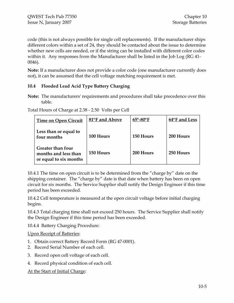
QWEST Tech Pub 77350 Chapter 10 Issue N, January 2007 Storage Batteries
10-5
code (this is not always possible for single cell replacements). If the manufacturer ships different colors within a set of 24, they should be contacted about the issue to determine whether new cells are needed, or if the string can be installed with different color codes within it. Any responses from the Manufacturer shall be listed in the Job Log (RG 41-0046).
Note: If a manufacturer does not provide a color code (one manufacturer currently does not), it can be assumed that the cell voltage matching requirement is met.
10.4 Flooded Lead Acid Type Battery Charging
Note: The manufacturers' requirements and procedures shall take precedence over this table.
Total Hours of Charge at 2.38 - 2.50 Volts per Cell
Time on Open Circuit Less than or equal to four months Greater than four months and less than or equal to six months
81°F and Above 100 Hours 150 Hours
65°-80°F 150 Hours 200 Hours
64°F and Less 200 Hours 250 Hours
10.4.1 The time on open circuit is to be determined from the “charge by” date on the shipping container. The “charge by” date is that date when battery has been on open circuit for six months. The Service Supplier shall notify the Design Engineer if this time period has been exceeded.
10.4.2 Cell temperature is measured at the open circuit voltage before initial charging begins.
10.4.3 Total charging time shall not exceed 250 hours. The Service Supplier shall notify the Design Engineer if this time period has been exceeded.
10.4.4 Battery Charging Procedure:
Upon Receipt of Batteries:
1. Obtain correct Battery Record Form (RG 47-0001). 2. Record Serial Number of each cell.
3. Record open cell voltage of each cell.
4. Record physical condition of each cell.
At the Start of Initial Charge:

Chapter 10 QWEST Tech Pub 77350 Storage Batteries Issue N, January 2007
10-6
1. Charging will begin after the first cell reaches -2.38 volts without any cell exceeding -2.50 volts. The output of the charger shall not exceed -60 volts.
2. During normal work days, record the voltage of each cell on Form RG 47-0001. 3. Charge the battery string for 100 – 250 hours.
At the Completion of Initial Charge:
1. The battery string voltage shall be between -57.12 and -60 volts (for a nominal -48V plant) or 28.56 to 30 Volts (for a nominal 24V plant).
2. Reduce the charge to the “float voltage” (preferably -52.80V or 26.40 for nominal 48V and 24V plants using 1.215 specific gravity long duration cells) of the existing power plant.
3. Wait 24 hours after reducing to float and recheck the average cell voltage (each nominal 1.215 specific gravity cell should measure between –2.14V and –2.27V per cell).
4. Contact the Local Power or Central Office Technician for acceptance.
Notes:
1. Charge procedures recommended in manufacturer's literature may be used in place of these.
2. Towards the end of initial charge (approximately 100 hours or more), individual cell readings for any single cell should remain constant for 3 successive hourly readings of that cell (that should be true of every cell).
10.5 Initial Charge and Turnover Requirements for Flooded Cells
10.5.1 Before stopping the initial charge, record the following:
• Total hours of charge.
• Presence or absence of crystals for each cell.
10.5.2 Cells/battery shall not be handled, other than voltage readings, during boost /initial charge or for 48 hours thereafter.
10.5.3 After a satisfactory initial charge, there should be no lead-sulfate crystals or gray coloration present on the positive plates or straps when examined with a nonmetallic flashlight. Normally only the positive strap will be accessible for examination. In some arrangements the edges of the positive plates will also be visible. The visible positive elements shall be black or dark brown and totally free of any diamond-like crystals or gray coloration. The disappearance of crystals normally occurs in three distinct phases:
• Phase 1: Black and crystalline
• Phase 2: Gray and lightly crystalline

QWEST Tech Pub 77350 Chapter 10 Issue N, January 2007 Storage Batteries
10-7
• Phase 3: Black or dark brown and crystal free
10.5.4 The disappearance of crystals or gray coloration occurs from top to bottom during initial charge. To ensure total absence of crystals or gray coloration, inspection for crystals should be concentrated at the bottom of the positive plate vertical columns. Crystals can readily be seen on the positive plate. Use a flashlight held close to the jar wall at an angle of approximately 45 degrees to inspect for crystals. The lead-sulfate crystals will appear as sparkling diamond-like reflecting particles or as a gray coloration on the normally black positive plates
10.5.5 Cells which are not free of crystals after the initial charge may be shorted. If some cells are still crystalline after initial charge, it is recommended that the battery string be continued on boost charge at -2.38 to -2.50 volts for a total charge time not to exceed 250 hours FOR BOTH CHARGES. If charging fails to clear the crystals within 250 hours, the cells should be referred to the Qwest Power Design Engineer.
10.5.6 For cells shipped dry, follow the same requirements for the end of the initial charge as outlined above.
10.5.7 The float voltage for nominal 1.125 specific gravity cells shall be either -2.17 or -2.20 Volts per cell average (in rare cases approved by the Power Maintenance Engineer, it can be set between those levels), depending on power plant configuration. Some older nominal -48 VDC power plants cannot easily have the float voltage raised to -52.8 V due to HVSD settings and other considerations. Nominal -48 VDC or 24 VDC power plants that will not function with a float voltage of -2.20 volts per cell are generally configured at the traditional -2.17 volts per cell , but may be configured at a slightly higher average voltage if the plant will allow.
10.5.8 Specific Gravity = 1.215 ±0.010 (high gravity UPS and engine-start batteries will have gravities such as 1.250, 1.280, 1.30, etc .
10.5.9 Electrolyte Level Adjustment
Electrolyte levels should be adjusted after the cells have been on two weeks of continuous float to maintain specific gravity of 1.215 ±0.010 (the± 0.10 applies to other specific gravities as well).
10.6 Initial Charge Procedures for Valve Regulated Lead Acid Cells
Note: The manufacturer's requirements and procedures shall be followed when installing and charging VRLA batteries. As a general rule, VRLA batteries should not be charged above normal float voltages for initial charge, boost charge, or any other reason. Any questions not answered by the manufacturer or documentation shall be referred to the Qwest Power Design Engineer or Qwest NROC Power Maintenance Engineer.
10.6.1 The float voltage shall be between -2.25 to -2.28 volts per cell unless otherwise required by the manufacturer.
Chapter 10 QWEST Tech Pub 77350 Storage Batteries Issue N, January 2007
10-8
10.6.2 All VRLA battery installations shall be -48v nominal or +/-24v nominal.
Caution: Served equipment must be able to tolerate voltages up to -54.8 volts (+2.0 volts).
10.6.3 Provide ventilation to avoid buildup of explosive hydrogen gas.
10.7 Charge Procedures for Lead Acid Cells Stored for Reuse Applications
10.7.1 Lead-acid batteries shall not be stored longer than 6 months without a freshening charge (48 hrs at 2.37 V/cell for flooded cells, and 48 hours at 2.33 V/cell for VRLA batteries). If they are stored longer than 6 months, or the time of storage since the last charge is unknown, take voltage readings. If the voltage of a cell (or average per cell in the case of a monoblock) is less than 2.01 for VRLA cells or 1.93 for a flooded cell, the battery is probably bad, and the procedures of Section 12.4 should be followed for disposal. Special exceptions should be discussed with the Qwest Power Maintenance Engineer and the battery manufacturer.
10.8 Electrolyte Spills
Reference: Chapter 12, “Hazardous Material Handling.”
Whenever a spill of electrolyte occurs, the Service Supplier shall:
10.8.1 Take steps to stop the flow of electrolyte.
10.8.2 Contain the flow of electrolyte by using a spill kit.
10.8.3 Take steps to neutralize any electrolyte coming in contact with the body.
10.8.4 Seek medical attention if necessary.
10.8.5 Report the incident immediately to UNICALL at 1-800-654-2525 when the spill has been contained.
10.9 Installation/Removal Requirements for Lithium-based Batteries
10.9.1 Lithium-based batteries do not generally need an initial charge unless specified by the manufacturer.
10.9.2 Ensure that any alarms available from the batteries are hooked up and working to either the plant, or an external alarm device. If they report to the plant, ensure that the plant forwards those alarms (can be part of a generic major or minor) to an external alarm reporting device.
10.9.3 Follow the manufacturer recommendations for storage (may require insertion of a storage plug, protection of terminals, turning off a switch, etc.).
10.9.4 If the internal LVD has operated (no charge current will flow into the battery, and the voltage is 39.5 V or less on a nominal -48 V battery) due to an excessively long storage time, contact the manufacturer for reset procedures (may require shipment back to the manufacturer in some cases).

QWEST Tech Pub 77350 Chapter 10 Issue N, January 2007 Storage Batteries
10-9
10.9.5 Lithium-based batteries do not require ventilation or spill containment.
10.9.6 Ensure that the batteries are strapped down in their tray or otherwise securely mounted to the relay rack (for those batteries with mounting ears) in heavy earthquake zone COs.
10.10 Installation Requirements for Nickel-based Batteries
10.10.1 Follow manufacturer recommendations for initial charging of Ni-Cad and NiMH batteries, if such charging is recommended by the manufacturer.
10.10.2 Ensure that the permanent rectifier/charger for NiMH batteries is designed for those batteries per the manufacturer recommendations.
10.10.3 For flooded Ni-Cad batteries, ensure that a spill kit designed for alkaline batteries is available on site. Such a spill kit will contain an acidic neutralizer, as opposed to the alkaline baking soda used for lead-acid batteries. Place a sign on the room door and near the batteries stating that baking soda is not to be used for neutralization of alkaline batteries.
10.10.4 Note that storage times without freshening charges for Nickel-based batteries are half of what they are for lead-acid batteries. This means that the maximum storage interval at 77 degrees Fahrenheit without a freshening charge is 3 months. Follow manufacturer recommendations for freshening charges.
10.10.5 Peform a baseline conductance test with a Midtronics test set on NiMH batteries approximately 1 week after they have been installed and placed on float charge. Write down the values, the date the test was performed, the instrument it was performed with, and place the data in the battery log book of the site.
10.10.6 Number the batteries and strings as would be done for lead-acid batteries.
10.10.7 Write the installation date on each battery.

QWEST Tech Pub 77350 Chapter 11 Issue N, January 2007 Bonding and Grounding
CONTENTS
Chapter and Section Page
11. Bonding and Grounding............................................................................. 11-1 11.1 General Requirements..................................................................... 11-1 11.2 Central Office and Facility Main Ground Systems ..................... 11-2 11.3 Grounding Frames, Bays and Cabinets ........................................ 11-3 11.4 Equipment Chassis Shield and Quiet Grounding
Connections ...................................................................................... 11-3 11.5 Isolated Ground Systems for Stored Program Control
Systems .............................................................................................. 11-4 11.6 Circuit Pack Storage Cabinets ........................................................ 11-5 11.7 Foreign Object Grounding.............................................................. 11-5 11.8 Minicomputer Systems ................................................................... 11-6 11.9 Facility and Radio Site Ground System ........................................ 11-7 11.10 Standby Engines and Engine Room Equipment ......................... 11-8 11.11 Fuel Storage Tanks and Fuel Lines................................................ 11-8 11.12 Girdling ............................................................................................. 11-9
Figures
11-1 Grounding For Integrated and Isolated Ground Planes Powered From Common Power Plant....................................................................... 11-10
11-2 Typical Sequence of Connections to a Separate Ground Window ....... 11-11
11-3 Tabulation of Typical Ground Window Connections ............................ 11-12
11-4 Using An Insulated Return Bus As The Ground Window .................... 11-13
11-5 Using A Noninsulated Return Bus As The Ground Window............... 11-14
TOC 11-i


QWEST Tech Pub 77350 Chapter 11 Issue N, January 2007 Bonding and Grounding 11. Bonding and Grounding
Note: It is required that a current copy of Qwest TP 77355, “Grounding Central Office and Remote Equipment Environments,” be present on site and available for use on any job that includes grounding. Any issues not addressed in this chapter are to be found and followed in the 77355.
The Architecture, Models, and Configurations (AMC) of some specific types of equipment and Qwest Drawing Standards may supersede some requirements identified in this chapter.
11.1 General Requirements
11.1.1 All grounding conductors shall be run exposed and supported to existing cable rack, hangers, or suitable framework using nylon/plastic tie wraps or No. 9 cord.
11.1.2 Grounding conductors No. 1/0 AWG and smaller may be secured directly to the side of cable racks, or run along walls and secured at 18” intervals.
11.1.3 Grounding conductors larger than No. 1/0 AWG shall be suspended on and secured to cable hangers or run along walls and secured at 18” intervals. Cable hangers shall be placed at eighteen-inch intervals.
11.1.4 Grounding conductors shall not be run within cable racks or attached to AC conduit.
11.1.5 All connections shall be made with a crimp compression parallel copper connector (C-tap or H-tap) or a two-hole crimp compression copper / tinned copper connector. Two-hole crimp connectors shall be secured with an approved lockwasher placed between the connector and the head of the screw or nut. Refer also to Par. 7.4.5.
11.1.6 Grounding conductors, bonds and taps to ground conductors shall be preferably arranged to flow fault currents in the direction of the OPGPB or ground source. This rule does not apply to buss bar assemblies.
11.1.6.1 180 degree bends in grounding conductors are not permitted.
11.1.6.2 Minimum bending radius of a grounding conductor is 12 inches.
11.1.7 All shielded cable and wire shall be grounded at one end or as directed in the job specification, drawing/record, or manufacturers' specification.
11.1.8 All chassis, shield, and equipment ground bonds may be made using a solderless wrapped connection, a soldered connection, or single hole ring type crimped connector mounted to a properly prepared surface of the frame, bay, or cabinet with suitable hardware and shakeproof lock washer. The placement of
11-1

Chapter 11 QWEST Tech Pub 77350 Bonding and Grounding Issue N, January 2007 the lock washer shall be between the head of the securing device and the connector, not between the connector and the contact surface.
11.1.9 Frame ground connectors, chassis, shield, and equipment bonds shall not be stacked one on top of the other under the same mounting hardware.
11.1.10 A grounding conductor shall not be secured or supported by metallic clamps which completely encircle the conductor ( see girdling Par. 11.12).
11.1.11 Stranded RHW or XHHW type insulated copper wire, where the insulation is colored green, is the standard interior central office grounding conductor (AC grounding conductors are typically green THWN). (In accordance with the NEC, wires other than “grounding” conductors shall not be colored green, with the exception of manufacturer wiring inside a bay or shelf. For example, the “grounded” -48 VDC battery return conductor[s] shall have insulation colored gray or black. Although green coloration is recommended for smaller wires, including chassis grounds, it is not required.) Alternately, bare copper wire (stranded or solid) is also allowable in some situations as specified in Qwest Standard Configuration documents.
11.1.12 Attachments to raceways shall only be made per NEC 300.11B.
11.1.13 Ground conductors shall be run so that they are visible from the floor.
11.1.14 Ground conductors shall be run so that they may be accessible throughout their expected life.
11.2 Central Office and Facility Main Ground Systems
11.2.1 The vertical ground riser shall be continuous (but may be spliced with a butt splice or straight-through exothermic weld) and free of sharp bends and contain no bends with a radius of less than 12 inches.
11.2.2 A No. 750-kcmil AWG ground conductor shall be run from the OPGP to the last CO ground bar in the vertical riser system. Any such cable is a vertical riser.
11.2.3 PVC or other nonmetallic sleeves are required for routing the vertical equalizer (or riser) through floors or walls. Metallic sleeves may be required by local codes. If running the conductor through a metallic sleeve is unavoidable, the sleeve should be less than 3 feet in length and both ends of the metallic sleeve shall be bonded with No. 6 AWG stranded copper wire to the conductor extended through that sleeve. Under no circumstances shall the installer run cable through non-sleeved holes.
11.2.4 The PVC sleeve shall extend four inches above and two inches below floor levels and be properly firestopped. See Chapter 4,” Cable Holes, Penetrations, and Fire/Smoke Protection.”
11-2

QWEST Tech Pub 77350 Chapter 11 Issue N, January 2007 Bonding and Grounding 11.2.5 A bond strap across the water meter is required. Water valves and pipe unions should be within the bond.
11.2.6 Exothermic weld connections on a ground well head shall be protected from the environment with a suitable polyurethane caulk or sealer such as “Vulkem", “450/451”, “Sikaflex - 1A”, or “Sonneborn", or with an antioxidant grease impregnated with copper particles.
11.3 Grounding Frames, Bays and Cabinets
See Qwest Technical Publication 77355 for additional information and requirements.
11.3.1 All frames, bays, and cabinets shall be individually grounded with a minimum No. 6 AWG green covered RHW, XHHW or bare AWG copper stranded wire as specified by Qwest Standard Configuration documents. Frames, bays and cabinets shall be welded steel type construction. No aluminum or bolted bays shall be allowed on new equipment additions.
11.3.2 In new BDFB installations (where the BDFB is fed from 600A fuses or breakers), the framework grounding lead will be sized at No. 1/0 AWG. In existing or reuse applications where BDFBs are fed from 225A, 400A, or 500A loads, the framework grounding lead may be as small as No. 2 AWG.
Note: When the 600A-fed BDFBs are installed, the main aisle toll grounding conductors will also be sized at No. 1/0 AWG or larger.
11.3.3 All ground connections shall be secure.
11.3.4 All contact surfaces shall be cleaned and treated with a non-oxidizing agent.
11.3.5 Frame support pipes shall not be used for frame grounds. If necessary, the installer shall contact the Design Engineer to arrange for the necessary material to provide a proper No. 2 AWG stranded, insulated, copper conductor, supported on hangers, extending the full length of the line up.
11.3.6 Frame, bay and/or stand extension supports (extenders) shall be bonded to the frame with a minimum No. 6 AWG conductor that shall not contain bends exceeding 90 degrees.
11.4 Equipment Chassis Shield and Quiet Grounding Connections
11.4.1 Chassis and shield grounds may be made using single-hole crimped compression connectors or by wire wrapping to an approved wire-wrap terminal. If a manufacturer provides a termination for a chassis, shield, or quiet ground, that bond shall be made. NEBS tested self-tapping screws and/or tooth-type lock washers are also approved for chassis grounding connections.
11-3

Chapter 11 QWEST Tech Pub 77350 Bonding and Grounding Issue N, January 2007 11.4.2 All shielded cable and wire intended to be provided with a quiet/shield ground, shall have its shield bonded to ground on one end or the other, but not on both ends unless specified by standard or manufacturers drawing. See Chapter 2, “General Requirements.”
11.5 Isolated Ground Systems for Stored Program Control Systems
11.5.1 Stored Program Control System (SPCS) switch Frames or Equipment shall not be located more than one floor away from the ground window.
11.5.1.1 A two-inch air separation or approved insulator is required between a member associated with the integrated (building) ground system and a member of the SPCS isolated ground system.
11.5.2 All frames, bays, and cabinets installed in an isolated ground plane shall have a low voltage (resistance) and a high voltage (breakdown) test applied prior to the installation of the frame ground conductor or any other cabling to assure that the frame is truly insulated. The results must appear in the test record documentation required to be turned over to the COO at the completion of the job.
11.5.2.1 Two wraps of sheet fiber paper/protective tubing or other approved insulator shall be used to isolate conduit and other members of the isolated ground plane from different grounding systems. Isolation material shall extend 2 inches on either side of the point of incidence.
11.5.2.2 Any AC raceway, communications circuit or ACEG conductors that have connections to both the integrated and isolated ground planes shall pass through the ground window and be bonded to the main ground bus.
11.5.3 Isolated Conduit and ACEG
11.5.3.1 The length of the bond lead to the main ground bus for conduit, raceway or grounding conductor entering the SPCS at integrated ground plane potential, shall not exceed three feet from the main ground bus and shall be connected to the integrated side.
11.5.3.2 The continuity of metallic conduit providing AC service shall not be broken by an air gap or insulating coupling.
11.5.3.3 The continuity of metallic conduit used for the routing of DC alarms and low voltage lighting control lead(s) into the SPCS environment shall be broken by an air gap or insulating coupling when the conduit is not routed through the ground window and bonded to the main ground bus.
11.5.4 The Main Ground Bus (MGB) in the Ground Window
11.5.4.1 The Main Ground Bus (MGB) in the Ground Window shall be connected to CO Ground with a No. 750-kcmil AWG Ground cable. The MGB in the
11-4

QWEST Tech Pub 77350 Chapter 11 Issue N, January 2007 Bonding and Grounding ground window shall be configured so that the CO ground connection is the separation of the isolated ground and integrated ground connections.
11.5.4.2 Only one “Ground Window” shall be provided per power plant when one or more SPCS switches share the same power plant. The power plant (positive bus in negative voltage systems) shall be ground referenced with a separate conductor to the MGB in the ground window.
11.5.5 Battery return leads for non-SPCS equipment sharing the SPCS power plant shall be bonded to the integrated side of the MGB in the ground window. The battery and return conductors shall be paired and closely coupled to the greatest extent practicable between the power plant and the equipment being powered. (see Section 9.3 “Battery Primary Conductors” for exceptions to this rule). Multiple return conductors from the same source may be bonded together with one bond to the MGB. The bonding lead shall not exceed three feet and shall be connected to the integrated side of the MGB.
11.6 Circuit Pack Storage Cabinets
11.6.1 Circuit pack storage cabinets located or placed in lineups with SPCS equipment shall be insulated from the integrated environment and bonded to the isolated ground.
11.6.2 Circuit pack storage cabinets that do not meet Paragraph 11.6.1 restrictions, that are located within six feet of SPCS equipment, shall be bonded to the Foreign Object Ground (FOG) system.
11.6.3 Circuit pack storage cabinets that do not meet the requirements of Paragraph 11.6.1 or 11.6.2 shall be grounded to the central office grounding system.
11.7 Foreign Object Grounding
Metallic Members of the integrated ground plane located within six feet of metallic members of the isolated ground plane shall be bonded to the Integrated portion of the Ground Window/Single Point Ground (SPG, MGB). Steps shall be taken to ensure that there is electrical continuity between members of the nearby metal mass, verifiable by a reading of less than 0.1-ohm resistance, measured between metallic members. If the reading is greater than 0.1 ohm across junctions, then the metal objects shall be deliberately bonded.
11.7.1 In areas adjacent to, and within 6 feet of, Isolated Ground Plane Systems the Service Supplier shall ensure that Foreign Object Ground paths are not disturbed. If equipment and ironwork that is Foreign Object Grounded is removed, the Service Supplier shall ensure that ground paths are properly reestablished to remaining equipment and ironwork. See Qwest Technical
11-5
Chapter 11 QWEST Tech Pub 77350 Bonding and Grounding Issue N, January 2007 Publication 77355, “Grounding Central Office and Remote Equipment Locations”, for additional information.
11.7.2 Metallic objects that are commonly found within the six-foot radius of an Isolated ground plane are listed, but not limited to: tip and ring cable racks, power cable racks, cable rack screening and panning, auxiliary framing including support rods and earthquake bracing, conduits, AC service panels, lighting fixtures, HVAC ducts, alarm panels, desks and cabinets, facility and radio equipment frames.
11.7.3 Care shall be taken to limit environmental contamination caused by dust, drilling, and or paint removal. Whenever possible, this work shall be performed outside the switch area or before the installation of switch equipment. If the work shall be done near the switch or other working equipment, then steps shall be taken to collect all dust, paint chips, and metal bits. The use of a HEPA vacuum cleaner and proper equipment protection such as canvas tarps, insulating blankets, or masonite is required.
11.7.4 Where switch frames or lineups are added to new or existing SPCS environments, the Service Supplier is required to provide the foreign object grounding. Some SPCS environments may not have existing foreign object grounding. In these instances, the Service Supplier is required to extend a No. 2 AWG stranded insulated conductor from the area above the switch to the integrated portion of the ground window, and bond metallic members within six feet of the added equipment.
11.7.5 Objects in the integrated ground plane may be extended individually to the integrated portion of the ground window or may be collectively referenced through a foreign object ground bar which is connected to the integrated portion of the ground window with a minimum No. 2 AWG stranded insulated conductor. It shall be permissible to branch No. 6 AWG conductors from the No. 2 AWG conductor to bond individual items.
11.8 Minicomputer Systems
Minicomputers referred to in this section are generally composed of several floor supported equipment cabinets, each equipped with one or more integral regulated power supply units served by a cord connected to AC service.
11.8.1 Minicomputer system cabinets (i.e., processor boxes, expansion cabinets, peripherals, communications cabinets, a floor mounted AC distribution center, and floor mounted air handling equipment) shall be grounded to the raised floor grid using a flat braided strap to the nearest floor grid-work structure. This arrangement provides the necessary high frequency return path and minimizes the difference of potential throughout the complex. The raised floor grid shall be connected to the CO ground system.
11-6

QWEST Tech Pub 77350 Chapter 11 Issue N, January 2007 Bonding and Grounding 11.8.2 All connections to the equipment cabinets and the raised floor metallic grid shall be made with two-hole crimped copper lugs.
11.8.3 Each minicomputer cabinet shall be connected to an AC supply system by means of an electrical cord equipped with an ACEG conductor (green wire).
11.8.4 AC outlets shall be NEMA-spec and compatible to the AC plugs provided by the minicomputer supplier, for each cabinet requiring AC connection.
11.8.5 Alternating current outlet boxes shall be NEMA-spec and metal to reduce noise.
11.8.6 The ACEG shall be extended to the equipment ground bus of the AC power service cabinet.
11.8.7 In no case shall the ACEG be interrupted.
11.8.8 In no case shall the ACEG be routed between the computer cabinets and the AC power service cabinet in other than cord and AC branch circuit raceway.
11.8.9 The Service Supplier shall ensure that AC service complies with the manufacturer's specifications. If the AC service is not in compliance, the Service Supplier shall contact the Qwest Design Engineer for resolution.
11.9 Facility and Radio Site Ground System
Reference: Qwest Communications Inc. Technical Publication 77355, “Grounding - Central Office and Remote Equipment Environment.”
11.9.1 Use only No. 2 AWG solid, tinned copper conductor for the construction of and bonding to the external ring ground system.
11.9.2 All bonds to the external ring ground shall be made using exothermic welds, exothermic welded connectors or irreversible crimp connections Listed for buried applications.
11.9.3 Use only insulated No. 2 AWG and No. 6 AWG stranded copper conductors for construction of the interior ring system.
11.9.4 All connections to the interior ring ground system shall be made with copper/tinned copper crimp compression connectors or other Qwest approved connectors.
11.9.5 The interior ring ground shall be bonded in at least two corners to the external ring ground solid conductors extended to the inside of the building using exothermic welds or two compression crimp copper C-taps or H-taps of the correct size placed in line with one another.
11-7
Chapter 11 QWEST Tech Pub 77350 Bonding and Grounding Issue N, January 2007 11.9.6 Wave-guide hatch plate(s) shall have two connections to the primary interior ring conductor, flowing in opposite directions. They shall also have a connection to the external ring ground.
11.9.7 The primary interior ring ground conductor shall be supported to the interior walls at two foot intervals and shall be constructed at either the seven foot or nine foot level, depending on the height of equipment frames.
11.9.8 The supplementary ring conductors shall be No. 2 AWG wire, extended down each equipment aisle, and supported using the cable rack runners and auxiliary framing bars. The conductors shall be connected at both ends to the primary system. Connections shall be formed in the direction of the wave guide hatch plate(s).
11.9.9 All bends and turns of conductors shall have a minimum radius of twelve inches. Bends and turns in a single conductor shall be kept to a minimum. Bond conductors shall be as short as possible while meeting above requirements. Refer also to Par. 5.3.
11.9.10 All frames, bays, cabinets, cable rack sections, auxiliary framing, conduits, vents, metal doors/frames, and other metallic objects within six feet of the radio equipment area shall be bonded to the ring ground system.
11.9.11 All frames, bays, and cabinets shall be bonded at or near the top of each side or upright to the supplementary ring conductor. Individual bonds shall be formed flowing toward the wave-guide hatch plate(s) in opposite directions. It shall be permissible to use a single conductor bonded to each upright and connected in the middle to the supplementary conductor.
11.10 Standby Engines and Engine Room Equipment
11.10.1 Standby engines located indoors shall be bonded to a COGB or OPGPB (preferably the OPGP) with a minimum No. 2 AWG stranded copper conductor routed away from equipment areas (maximum of 200’), and attached to the engine support framework with a two hole connector. This conductor shall also be used to branch No. 6 AWG stranded copper conductors to bond other metallic objects and equipment within the engine room. Mechanical connectors shall not be permitted.
11.10.2 The standby engine shall be bonded to engine support framework.
11.10.3 Ground bonds shall be extended to all metallic objects such as: day tanks, in-room fuel tanks, start battery stands, AC panels, air intake louvers, transfer switches, conduits, remote engine shut-off switches, alarm control boxes, etc plus any metallic items extending outside, such as radiator pipes, exhaust, etc.
11-8
QWEST Tech Pub 77350 Chapter 11 Issue N, January 2007 Bonding and Grounding 11.10.4 Bonds shall be placed around flexible metallic conduits that are terminated with mechanical connectors. Flexible sections in exhaust and fuel pipe systems shall also be connected on both sides to the grounding system or have a bond strap around them.
11.10.5 A No. 6 AWG bond shall be placed across flexible non-metallic sections of raceway.
11.10.6 Standby engines located outdoors will ground and bond as above except that the No. 2 AWG conductor shall connect to the exterior perimeter ground system instead of an interior bar.
11.10.7 External items associated with the engine that are located outdoors (radiators, fuel tanks, etc.) shall bond to the exterior perimeter ground system.
11.11 Fuel Storage Tanks and Fuel Lines
11.11.1 Buried metallic fuel tanks shall be grounded (with No. 2 AWG solid) to the external building ground ring. If it is not acceptable, they shall be grounded to the OPGP, entering the building as close as possible to the OPGP. Aboveground metallic tanks and outdoor metallic fuel lines should follow the same policy (the outdoor fuel lines are exempt if they connect to an already-grounded outdoor metallic tank). For indoor fuel tanks and fuel lines, bond them to the engine room No. 2 AWG main conductor.
11.11.2 Above ground fuel storage tanks shall be grounded in accordance with their specific situations and in compliance with Qwest TP 77355, “Grounding Central Office and Remote Equipment Environments.”
11.11.3 Connections made in exposed outdoor environments shall be protected from the environment with a suitable polyurethane caulk or sealer such as “Vulkem", “450/451”, “Sikaflex - 1A”, or “Sonneborn", or with an antioxidant grease infused with copper particles.
11.12 Girdling
Girdling refers to the encirclement of single grounding conductors by a ring of ferromagnetic metal. Refer to Qwest TP 77355.
This occurs in these typical situations:
• Steel conduit used for physical protection of conductors. • Steel rings used for supporting conductors.
11-9

Chapter 11 QWEST Tech Pub 77350 Bonding and Grounding Issue N, January 2007
Integrated Ground Plane (Building Steel)
Building Steel
VerticalEqualizer(Riser)
WaterPipe
OPGP
to Office Ground Electrode Field
Shared Power Plant Frameto otherconnections
COGB
COGB
insulated -48 V plant return bus+
_
Main Ground Bus(MGB)
Integrated Ground Plane System Frames
3’ radius
incidental grounds
with Frame (multi-grounded) Returns
with separateReturns
groundreferenceconductor
Horizontal Equalizer
return -48V return -48V
DigitalIsolatedGround Plane -48V
-48V returninsulated from frame
insulated frameground bus Ground
Window
framegroundingconductorpaired
conductors closely coupled
frame groundingwire
paired
paired
paired
paired
DigitalIsolatedGround Plane -48V
-48V returninsulated from frame
insulated frameground bus
paired
Figure 11-1: Grounding for Integrated and Isolated Ground Planes Powered From Common Power Plant
11-10

QWEST Tech Pub 77350 Chapter 11 Issue N, January 2007 Bonding and Grounding
To Isolated Ground Plane FramesContaining Loads Powered fromthese Sources together with “Hot”and Retrun Leads
ISOLATEDGROUNDPLANE CONNECTIONS
INSULATED MAIN GROUND BUS
Grounding Electrode Conductor
GROUND WINDOW
To Set of IsolatedGround Plane FramesOn the Same Floor
3 FOOT RADIUS MAXIMUM
1
2
3
4
5
6
7
8
9
10
To insulated -48 VDCReturn Bus in thePrincipal Power Plant
TO CO GROUNDINTEGRATEDGROUNDPLANE CONNECTIONS
To the Frame of thePrincipal Power Plant
ACEG (AC EquipmentGrounding) Wire andConduit
To AC Circuit Source Ground Bus
To AC Circuit Source Ground Bus
To Isolated Ground PlaneOutlets’ GRD Terminal togetherwith Phase and Neutral Leads
To Isolated Ground PlaneLighting Fixture Frames togetherwith Phase and Neutral Leads
To Logic and OtherGround Reference Leads
11
18
12
13
14
15
16
17
To Isolated Return Bus in OtherSeparately Derived DC or AC PowerSources Powering Loads in theIsolated Ground Plane (e.g., 130 VDC)
To the MDF and/or Cosmic Framewhen on the Same Floor as the MGB
To Nearby Integrated Ground Plane Frames thatPose a Potential Personnel Shock Hazard
To –48 Volt Return BusIn the –48 Volt Power Plant
To –48 Volt Retunr BusIn the –48 Volt Power Plant
To –48 Volt Return TollIntegrated Ground Plane Loads
To Section of a Set of Isolated GroundPlane Frames that Might be RadiallyGrounded (this wire might be duplicatedfor other sets of frames or adjacent floors)
To Set of Isolated Ground PlaneFrames on Upper Adjacent Floor
To Set of Isolated Ground PlaneFrames on Lower Adjacent Floor
All Metallic Parts Shall Be Insulated fromBuilding Steel because They Are Part ofthe Isolated Ground Plane
To –48 Volt Return TollIntegrated Ground Plane Loads
Figure 11-2: Typical Sequence of Connections to a Separate Ground Window
11-11

Chapter 11 QWEST Tech Pub 77350 Bonding and Grounding Issue N, January 2007
Can Conduct LightningCurrent
Fault Current
Required in All Plants
Conductor Identification
(see Figure 11-2) Yes No Yes No Yes No
Required in Some Plants (Yes)
Wire Size
(AWG)
1
External Power Sources Grounding Conductors x
x
x x
#6
2
Principal Power Supply Grounding Electrode Conductor
x x
x
750 kcmil
3
Main Ground Bus to CO Ground (COGB) Connection x
x
x
750 kcmil
4 Principal Power Plant Frame
Ground Reference Wire x x x
1/0: <50’ 4/0: 50-100’ 350: 100-150 500: 150-200’
750: >200’
5 6
External Power Sources Grounding Conductors x
x
x x
#6
7
Main Distributing Frame (MDF) and/or Cosmic Frame Protector Frames’ Grounding Wires (only applies when this frame is on the same floor as the MGB)
x
x
x
x
1/0
8
Grounding Wires for Nearby Integrated Ground Plane Frames that are a Shock Hazard
x
x
x x No. 6 (for
individual frames), or #2 tor collector
bar/cable
9 Toll (Integrated Ground Plane) Loads’ –48 V Return Leads (probably multiple leads)
x
x
x x same size as the load conductor (maximum 1/0)
10
Connection bar for coax shields and other shield wires connected to the isolated plane
x
x
x x
No.6
11
Continuation of Grounding Conductor (and Conduit) from Associated External Sources
x x
x
same size as the associated phases
and neutral 12 -
15
Isolated Ground Plane Grounding Conductors
x x
x
1/0 minimum
16 17
Continuation of Grounding Conductor (and Conduit) from Associated External Sources
x x
x
same size as the associated phases
and neutral
18 Logic and other "Quiet" Ground Reference Leads x x x per equipment
vendor
11-12

QWEST Tech Pub 77350 Chapter 11 Issue N, January 2007 Bonding and Grounding
Figure 11-3: Tabulation of Typical Ground Window Connections
11-13
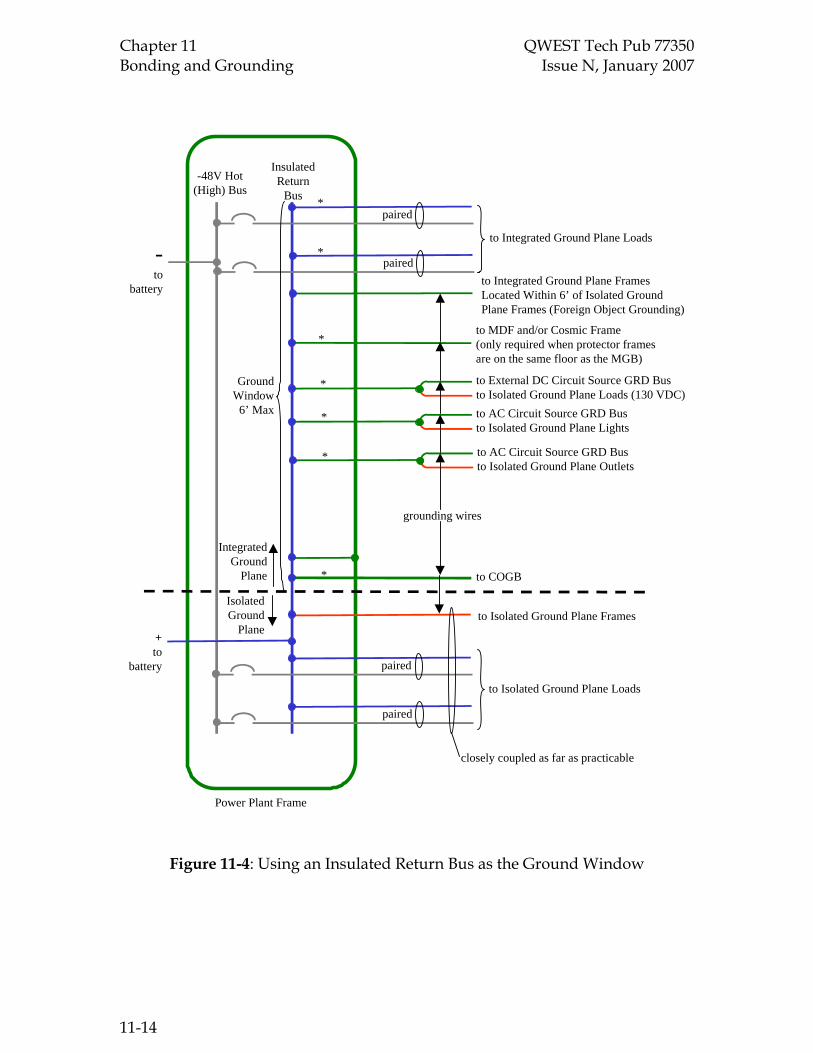
Chapter 11 QWEST Tech Pub 77350 Bonding and Grounding Issue N, January 2007
Power Plant Frame
-48V Hot(High) Bus
InsulatedReturn
Bus
-to
battery
+to
battery
paired
paired
to Integrated Ground Plane Loads
paired
paired
to Isolated Ground Plane Loads
to Isolated Ground Plane Frames
closely coupled as far as practicable
IsolatedGround
Plane
GroundWindow
6’ Max
IntegratedGround
Plane
to Integrated Ground Plane FramesLocated Within 6’ of Isolated GroundPlane Frames (Foreign Object Grounding)
to MDF and/or Cosmic Frame(only required when protector framesare on the same floor as the MGB)
to External DC Circuit Source GRD Busto Isolated Ground Plane Loads (130 VDC)to AC Circuit Source GRD Busto Isolated Ground Plane Lights
to AC Circuit Source GRD Busto Isolated Ground Plane Outlets
to COGB
*
*
*
*
*
*
*
grounding wires
Figure 11-4: Using an Insulated Return Bus as the Ground Window
11-14

QWEST Tech Pub 77350 Chapter 11 Issue N, January 2007 Bonding and Grounding
Power Plant Frame
-48V Hot(High) Bus
Non-InsulatedReturn
Bus
-+
paired
paired
to Integrated Ground Plane Loads
paired
paired
to Isolated Ground Plane Loads
to Isolated Ground Plane Frames
closely coupled as far as practicable
GroundWindow
6’ Max
to Integrated Ground Plane FramesLocated Within 6’ of Isolated GroundPlane Frames (Foreign Object Grounding)
to MDF and/or Cosmic Frame(only required when protector framesare on the same floor as the MGB)
to External DC Circuit Source GRD Busto Isolated Ground Plane Loads (130 VDC)to AC Circuit Source GRD Busto Isolated Ground Plane Lights
to AC Circuit Source GRD Busto Isolated Ground Plane Outlets
to COGB
*
*
*
*
*
*
*
grounding wires
tobattery
Added Insulated Auxiliary Return Bus(Within or Above the Power Plant Frame)for Isolated Ground Plane Connections
spacing between these terminationsshould be as small as practicable
Figure 11-5: Using a Non-insulated Return Bus as the Ground Window
11-15
QWEST Tech Pub 77350 Chapter 12 Issue N, January 2007 Central Office Equipment Removals, Installs and the Proper Handling of Hazardous Materials
CONTENTS
Chapter and Section Page
12. Central Office Equipment Removals, Installs and the Proper Handling of Hazardous Materials ...................................................................................... 12-1 12.1 Introduction ......................................................................................... 12-1 12.2 The independent contractor is responsible for: .............................. 12-1 12.3 Equipment Bays And Mercury- Containing Equipment .............. 12-1 12.4 Batteries- Flooded Lead Acid ............................................................ 12-2 12.5 PCB-containing Capacitors And Ballasts ........................................ 12-4 12.6 Radioactive Tubes............................................................................... 12-4 12.7 Fluorescent Light Tubes..................................................................... 12-4 12.8 Asbestos Floor Tile.............................................................................. 12-4 12.9 Spills and Emergencies....................................................................... 12-5 12.10 Radiography/x-ray............................................................................. 12-5
Table
12-1 Quick Reference Guide for Hazardous Materials by Facility Type......... 12-6
12-2 Environmental, Health & Safety Departmental Contact List ................... 12-7
TOC 12-i


QWEST Tech Pub 77350 Chapter 12 Issue N, January 2007 Central Office Equipment Removals, Installs and the Proper Handling of Hazardous Materials 12. Central Office Equipment Wreckouts and Installs: Hazardous Materials
12.1 Introduction
Equipment that is removed from the Qwest network pending retirement and/or removal of service will be designated per par. 8.19.5. When handling hazardous materials, waste materials, and equipment, the contractor is expected to comply with all applicable local, state, and federal environmental and transportation laws, regulations and ordinances.
The intent of this chapter is to make clear what activities the contractor is responsible for performing, and to alert the contractor to potentially hazardous materials present in the central office and in the switch equipment.
12.2 The Qwest Supplier is responsible for:
12.2.1 Compliance with applicable local, state, and federal environmental and safety laws, regulations and ordinances.
12.2.2 Development and implementation of there own environmental and safety programs.
12.2.3 Coordinating and ensuring compatibility of their safety, health, and environmental programs with other employers including Qwest, when other employers are present at the workplace.
12.2.4 Prompt correction of all violations of applicable environmental and safety regulations within the scope of the independent contractor’s work.
12.2.5 Indemnifying and holding Qwest harmless from any and all environmental, health and safety liabilities assessed against the independent contractor or Qwest, as a result of the contractor’s conduct.
12.2.6 Being aware of and adhering to the Qwest Safety and Loss Prevention Program.
12.3 Equipment Bays and Mercury-Containing Equipment
During a Central Office equipment replacement, the old equipment will be broken down - to the largest possible piece that can be safely lifted and moved out of the Central Office for transportation to the Qwest Materials Reclamation Center (MRC).
12.3.1 Individual components are not to be broken down at the Central Office. A Qwest employee will call the SMC (Qwest-Ryder Shipment Management Center on 877-879-7447) to arrange for the old equipment to be transported to the MRC or a "pack-n-hold" warehouse. If a Qwest employee is not available to call the SMC, then the contractor may call them. However, they need to have these three
12-1

Chapter 12 QWEST Tech Pub 77350 Central Office Equipment Removals, Installs Issue N, January 2007 and the Proper Handling of Hazardous Materials
•
pieces of information traceable back to the Design Engineering organization available before calling the SMC:
• RC code
• GEO-location code
main and sub account numbers
12.3.2 Transportation to the MRC (or "pack-n-hold" warehouse) is coordinated by the SMC. A Qwest employee must sign the transportation document.
12.3.3 The MRC will handle purging of the individual electronic components and subsequent recycling and/or disposal. THERE IS TO BE NO PURGING (REMOVING) OF MERCURY COMPONENTS OR OTHER HAZARDOUS COMPONENTS AT THE CENTRAL OFFICE. The only exception to this is glass tubes containing krypton or radium; these should be removed and placed in appropriate containers for transport to the MRC.
12.3.4 It is the contractor's responsibility to ensure that the equipment removed is properly loaded to ensure that no damage occurs during transport to the MRC. In addition, the equipment bays and frames must be adequately protected from weather and sunlight before the shipment is sent to the MRC.
• They must be loaded to ensure that no components of the bay or frame become separated from the bay/frame.
• There must be no damage to the switch equipment during transport to the MRC.
12.4 Batteries- Flooded Lead Acid
The Service Supplier performing the installation and/or removal may be moving flooded lead acid batteries within the same building - from their operating location to a pallet or to a specific part of the building. Flooded lead-acid batteries that are ready to be shipped off-site (anywhere outside of the building) are moved and packaged only by certain contractors specifically hired to move them. If the batteries are going to the designated recycling facility or to another Qwest building, they are only to be moved by the contractor specifically hired for moving wet batteries. Currently, there is one main flooded battery transporter that should be used. This contractor’s employees are specifically trained in moving, packaging, labeling, and transporting flooded batteries. Contact your Environmental Manager for information on this company or call the Qwest AIMS Logistics Shipment Management Center (SMC) at 1-877-879-7447. These batteries are not to be sent to the MRC. When arranging movement of batteries from one Qwest facility to another, the Service Supplier shall complete a Bill of Lading (RG33-0017) and list the BVAPP of the job installing the batteries and the
12-2

QWEST Tech Pub 77350 Chapter 12 Issue N, January 2007 Central Office Equipment Removals, Installs and the Proper Handling of Hazardous Materials location of the new site. The Supplier will also complete an AIMS Manual Shipment Request Form and fax to the number listed on the bottom of the form. This form can be obtained from AIMS Logistics. Make sure to note that batteries are for reuse and are considered Hazardous material. Ryder AIMS Logistics Shipment Management Center (SMC) at 1-877-879-7447. These batteries are not to be sent to the MRC. The Service Supplier is required to follow all applicable environmental and safety regulations when moving these batteries including the proper completion of form REGN 154-004-001RG (Refer also to Par. 14.23) which can be found at http://www.qwest.com/techpub/. This form ensures Qwest’s compliance with Environmental, Health & Safety requirements for the reporting of hazardous chemicals. When completed, it should be faxed to the appropriate Qwest EHS representative listed on Table 12-2. The original form should be sent to the Work Management Center (WMC) in Englewood, CO as part of the normal forms process flow associated with any typical installation. A copy shall also be retained in the Job Packet envelope that is stored at the central office location. Refer also Par. 14.28.
12.4.1 VRLA Battery Removals/Transportation
Removal and transportation requirements are different for Valve Regulated battery technologies. These batteries have electrolyte that has been immobilized with some type of component or process, and do not present the same hazards as a flooded cell battery. These batteries can be transported for short distances to another site or shipping location. When transporting or arranging for transport of VRLA batteries, the following process applies:
1. If the batteries are reusable, they can be transported by any company or carrier. Appropriate safety procedures in handling and securing batteries for transport must be followed. The batteries must be transported using a standard Bill or Lading. The proper shipping name for VRLA batteries is: Batteries, wet, non-spillable, 8, UN2800, PGIII
2. If the batteries are no longer useful, the batteries may still be transported by any company or carrier to a consolidation point at another site, to a Qwest MRC, or arrangements for pickup at the facility can be made by contacting the Shipment Management Center (SMC). Unusable VRLA batteries are, by definition, a “Universal Waste” which does not require specially permitted transportation. The batteries must be transported using a standard Bill of Lading. The proper shipping name for VRLA batteries is: Batteries, wet, non-spillable, 8, UN2800, PGIII.
12-3

Chapter 12 QWEST Tech Pub 77350 Central Office Equipment Removals, Installs Issue N, January 2007 and the Proper Handling of Hazardous Materials 12.5 PCB-containing Capacitors And Ballasts
Small capacitors and light ballasts manufactured through 1978 may contain PCB’s (polychlorinated biphenyls). Capacitors and ballasts should not be removed from the equipment bay.
12.6 Radioactive Tubes
These tubes are glass, usually painted black or purple, and range in size from 1 to 3 inches. See Table 12-1.
These are normally removed from the equipment bay to avoid any breakage during transport. (These tubes are the only hazardous component that is allowed to be removed at the C.O. before transport.) When removed, they should be properly packaged so that no damage occurs during transport. They are to be shipped to the MRC.
12.7 Fluorescent Light Tubes
If the Service Supplier removes any fluorescent light tubes, these should be properly packaged and sent to the MRC. The contractor is responsible for proper packaging to ensure that the tubes do not break during transport to the MRC. Alternately, these light tubes may be stored at the Central Office in a cardboard box of the proper size, and picked up directly by the Qwest transporter for shipment to one of our approved lamp recyclers. Check with the state Environmental Manager if you have any questions.
12.8 Asbestos Floor Tile
During C.O. equipment installs, the contractor may be drilling or handling floor tiles. The floor tiles in many buildings may contain asbestos. Since the regulations governing the removal of asbestos containing materials vary by state, contact should be made with the state Environmental Manager before disturbing any potential asbestos containing materials. The independent contractor must follow all applicable safety, health and environmental regulations governing asbestos containing materials.
The contractor is expected to properly bag and label asbestos-containing floor tile that he/she generates, and to contact the state Environmental Manager or the NTC (Qwest National Traffic Center) to arrange for disposal at the proper facility. Refer also to Par. 3.20, 14.1 and RG 09-1031.
During an equipment removal, no asbestos-containing materials should be removed from equipment bays.
Other asbestos containing building materials that the contractor may encounter include:
12-4

QWEST Tech Pub 77350 Chapter 12 Issue N, January 2007 Central Office Equipment Removals, Installs and the Proper Handling of Hazardous Materials • spray-on fireproofing
• transit walls, siding, ceilings
• insulating material on boilers, chillers, pipes, air plenums, ducts, piping, steam tunnels, mechanical rooms
• roofing materials
• telephone conduit
Information regarding friable asbestos-containing building materials can be found in the asbestos management plan posted at each facility.
12.9 Spills and Emergencies
In the event of spills or leaks of hazardous materials, the spill will be immediately contained and cleaned up in order to minimize impact. The contractor will follow all applicable laws, rules, and regulations regarding management of the spill. They will also follow their own company’s existing safety and environmental procedures and practices to ensure the safety of their own personnel and others that may be present.
In the event of a spill, it should be reported to UNICALL at 1-800-654-2525. The state Environmental Managers can also be contacted through the UNICALL number.
12.10 Radiography/x-ray
12.10.1 Prior to starting work, the service supplier must visually survey the building and the proposed work area for personnel exposure, floor by floor, and notify all persons about the potential for exposure to radiation and to assure that the exposure area is clear of personnel for the duration of the work.
12.10.2 Prior to starting work, the service supplier must post warning signage on exterior doors or at safe perimeter distances from the exposure area to warn personnel.
12.10.3 During each radiographic operation the service supplier shall maintain continuous direct visual surveillance of the operation to protect against unauthorized entry into a high radiation area.
12.10.4 The service supplier shall make the above a part of the MOP and include the methodology to be employed.
12.10.5 The service supplier shall be aware of and adhere to the Code of Federal Regulations (CFR) covering the work operations and refer to them in the MOP.
12-5

Chapter 12 QWEST Tech Pub 77350 Central Office Equipment Removals, Installs Issue N, January 2007 and the Proper Handling of Hazardous Materials Table 12-1: Quick Reference Guide for Hazardous Materials by Facility Type
Analog ESS
Digital ESS
Power
Trans Equip.
Radio Sites
CEVs, Huts, Etc.
Customer Premise
MERCURY Relays Mercury Vapor Tubes Ringing Machines Circuit Packs
X
X
X
X
X
X X
X
X
X
X
X
X
X
X PCBs Ballasts/ Transformer
X
X
X
X
X
X
X RADIO-ACTIVE TUBES
X
X
X
X
X
ASBESTOS Resistors Washers Floor Tiles Sheet Heat Shield Black Fuse Panels
X X X
X
X X X
X
X
X X X
X X X
X
X
X
X
X
BATTERIES Lead Acid/ Gel Cells Other Types
X
X
X X
X
X X
X X
X X
LEAD Cable Sleeves Battery Straps
X X
X X
X
X X
X X
X
X X
X
X X
X MISC. Solvents, Paints, CFCs, Etc.
X X X X X X X
12-6
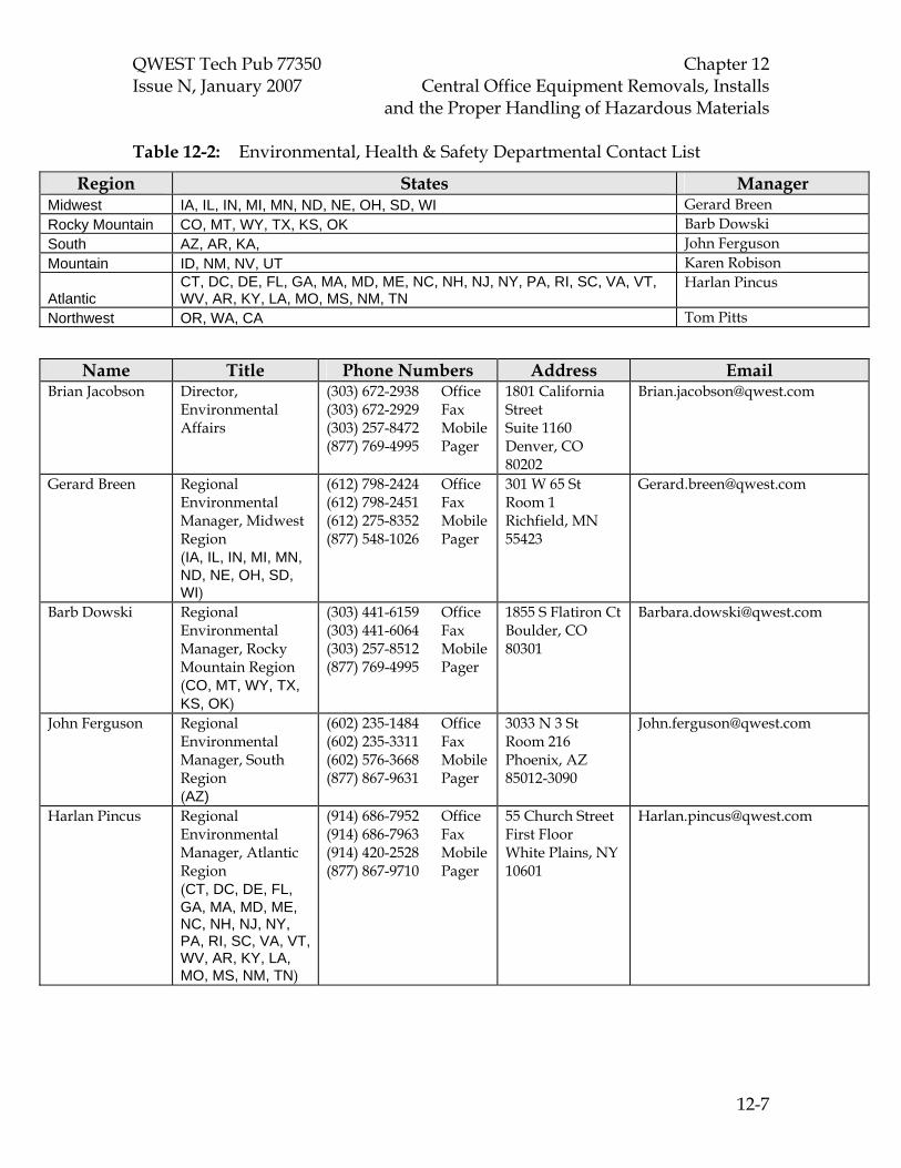
QWEST Tech Pub 77350 Chapter 12 Issue N, January 2007 Central Office Equipment Removals, Installs and the Proper Handling of Hazardous Materials Table 12-2: Environmental, Health & Safety Departmental Contact List
Region States Manager Midwest IA, IL, IN, MI, MN, ND, NE, OH, SD, WI Gerard Breen Rocky Mountain CO, MT, WY, TX, KS, OK Barb Dowski South AZ, AR, KA, John Ferguson Mountain ID, NM, NV, UT Karen Robison
Atlantic CT, DC, DE, FL, GA, MA, MD, ME, NC, NH, NJ, NY, PA, RI, SC, VA, VT, WV, AR, KY, LA, MO, MS, NM, TN
Harlan Pincus
Northwest OR, WA, CA Tom Pitts
Name Title Phone Numbers Address Email Brian Jacobson Director,
Environmental Affairs
(303) 672-2938 Office (303) 672-2929 Fax (303) 257-8472 Mobile (877) 769-4995 Pager
1801 California Street Suite 1160 Denver, CO 80202
Gerard Breen Regional Environmental Manager, Midwest Region (IA, IL, IN, MI, MN, ND, NE, OH, SD, WI)
(612) 798-2424 Office (612) 798-2451 Fax (612) 275-8352 Mobile (877) 548-1026 Pager
301 W 65 St Room 1 Richfield, MN 55423
Barb Dowski Regional Environmental Manager, Rocky Mountain Region (CO, MT, WY, TX, KS, OK)
(303) 441-6159 Office (303) 441-6064 Fax (303) 257-8512 Mobile (877) 769-4995 Pager
1855 S Flatiron Ct Boulder, CO 80301
John Ferguson Regional Environmental Manager, South Region (AZ)
(602) 235-1484 Office (602) 235-3311 Fax (602) 576-3668 Mobile (877) 867-9631 Pager
3033 N 3 St Room 216 Phoenix, AZ 85012-3090
Harlan Pincus Regional Environmental Manager, Atlantic Region (CT, DC, DE, FL, GA, MA, MD, ME, NC, NH, NJ, NY, PA, RI, SC, VA, VT, WV, AR, KY, LA, MO, MS, NM, TN)
(914) 686-7952 Office (914) 686-7963 Fax (914) 420-2528 Mobile (877) 867-9710 Pager
55 Church Street First Floor White Plains, NY 10601
12-7

Chapter 12 QWEST Tech Pub 77350 Central Office Equipment Removals, Installs Issue N, January 2007 and the Proper Handling of Hazardous Materials
Tom Pitts Regional Environmental Manager, Northwest Region (CA,OR,WA)
(206) 346-7532 Office (206) 375-8705 Fax (206) 551-3406 Mobile (877) 326-6899 Pager
1600 7th Ave Room 2206 Seattle, WA 98191
Kevin Robison Regional Environmental Manager Northwest Region
(801) 237-3006 Office (801) 237-5334 Fax (801) 598-3020 Mobile (877) 441-1199 Pager
250 E. 2nd St. Salt Lake City, UT 84111
Robin Seguin Environmental Project Manager
(303) 992-7091 Office (303) 992-7111 Fax (720) 209-3540 Mobile
1801 California Street Suite 1160 Denver, CO 80202
12-8

QWEST Tech Pub 77350 Chapter 13 Issue N, January 2007 Documentation
TOC 13-i
CONTENTS
Chapter and Section Page
13. Documentation ........................................................................................................13-1 13.1 General..........................................................................................................13-1 13.2 Forms List.....................................................................................................13-1 13.3 Packet Envelope ..........................................................................................13-2 13.4 Contents of Job Packet................................................................................13-3 13.5 Job Log..........................................................................................................13-4 13.6 Job Completion or Extension Reporting RG 47-0002.............................13-4 13.7 Job Information Memorandum (JIM) RG 47-0004..................................13-5 13.8 Service Interruption/Degradation Report RG 47-0013 .........................13-6 13.9 Request For Disposition of Qwest Communications Material
RG47-0010 ....................................................................................................13-6 13.10 Test Records.................................................................................................13-7


QWEST Tech Pub 77350 Chapter 13 Issue N, January 2007 Documentation
13-1
13. Documentation
Note: Only Qwest Forms shall be used.
13.1 General
The Service Supplier shall be responsible for the accurate completion and distribution of all current versions applicable forms and documents, including those specified in Chapter 12, “Central Office Equipment Removals, Installs and the Proper Handling of Hazardous Materials.” The Qwest forms listed in this section shall be complete, legible, accurate, in ink and used without any alteration (except where specifically noted in this and other sections). Note: Qwest Technical Installation (QTI) is allowed to use equivalent electronic versions of all required forms that are currently available in Qwest’s internal Installation Order Tracking (IOT) system. The QTI installation representative is responsible for ensuring that all information from the paper version of each form can be recorded on the IOT version as well.
13.2 Forms List
Form Number Description TP 77350 Ref. Par.
RG 33-0017 Straight Bill of Lading (BOL) 14.1
RG 33-0043 Document and Material Disposition 14.2
RG 41-0046 Job Log 14.3
RG 41-0170 Installation Alarm Assignment and Capacity Sheet 14.4
RG 41-0173 Alarm/OSS Testing Incompletion Tag 2.7.1.1; 8.25
RG 47-0001 Storage Battery Report 14.5
RG 47-0002 Installation Revised /Completion Notice 14.6
RG 47-0004 Job Information Memorandum 14.7
RG 47-0005 Method of Procedure Page 1 14.8
RG 47-0009 Report of Equipment Disconnected form Existing Plant 14.9
RG 47-0010 Request for Disposition of Qwest Communications 14.10
RG 47-0013 Service Interruption / Degradation Report 14.11
RG 47-0130* Frame Upright Equipment Designation Label 8.22
RG 47-0131* Base Plate or Cover Equipment Designation Label 8.22
RG 47-0132* Cable Hole Open Label 4.6
RG 47-0133* Fire Stopped Cable Hole Label 4.6
RG 47-0157 Test Record (COE) 14.12
RG 47-0160 CLEC Provisioning Form 14.13
RG 47-0161 Quality Checklist 14.14
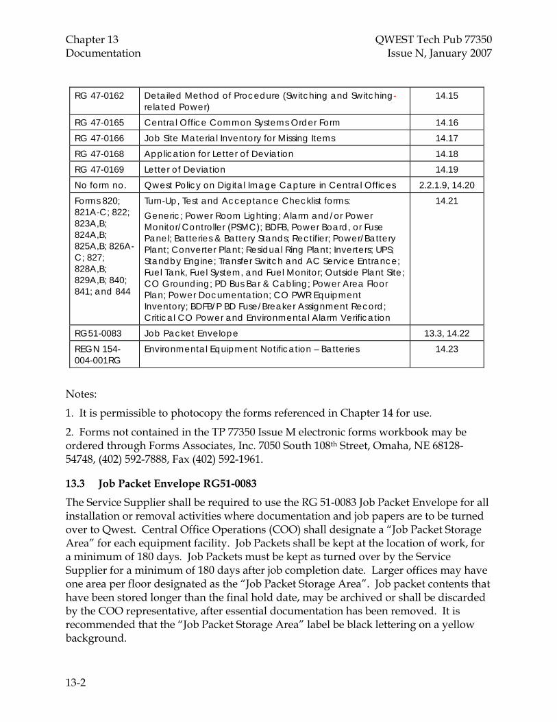
Chapter 13 QWEST Tech Pub 77350 Documentation Issue N, January 2007
13-2
RG 47-0162 Detailed Method of Procedure (Switching and Switching-related Power)
14.15
RG 47-0165 Central Office Common Systems Order Form 14.16
RG 47-0166 Job Site Material Inventory for Missing Items 14.17
RG 47-0168 Application for Letter of Deviation 14.18
RG 47-0169 Letter of Deviation 14.19
No form no. Qwest Policy on Digital Image Capture in Central Offices 2.2.1.9, 14.20
Forms 820; 821A-C; 822; 823A,B; 824A,B; 825A,B; 826A-C; 827; 828A,B; 829A,B; 840; 841; and 844
Turn-Up, Test and Acceptance Checklist forms: Generic; Power Room Lighting; Alarm and/or Power Monitor/Controller (PSMC); BDFB, Power Board, or Fuse Panel; Batteries & Battery Stands; Rectifier; Power/Battery Plant; Converter Plant; Residual Ring Plant; Inverters; UPS; Standby Engine; Transfer Switch and AC Service Entrance; Fuel Tank, Fuel System, and Fuel Monitor; Outside Plant Site; CO Grounding; PD Bus Bar & Cabling; Power Area Floor Plan; Power Documentation; CO PWR Equipment Inventory; BDFB/P BD Fuse/Breaker Assignment Record; Critical CO Power and Environmental Alarm Verification
14.21
RG51-0083 Job Packet Envelope 13.3, 14.22
REGN 154-004-001RG
Environmental Equipment Notification – Batteries 14.23
Notes:
1. It is permissible to photocopy the forms referenced in Chapter 14 for use.
2. Forms not contained in the TP 77350 Issue M electronic forms workbook may be ordered through Forms Associates, Inc. 7050 South 108th Street, Omaha, NE 68128-54748, (402) 592-7888, Fax (402) 592-1961.
13.3 Job Packet Envelope RG51-0083
The Service Supplier shall be required to use the RG 51-0083 Job Packet Envelope for all installation or removal activities where documentation and job papers are to be turned over to Qwest. Central Office Operations (COO) shall designate a “Job Packet Storage Area” for each equipment facility. Job Packets shall be kept at the location of work, for a minimum of 180 days. Job Packets must be kept as turned over by the Service Supplier for a minimum of 180 days after job completion date. Larger offices may have one area per floor designated as the “Job Packet Storage Area”. Job packet contents that have been stored longer than the final hold date, may be archived or shall be discarded by the COO representative, after essential documentation has been removed. It is recommended that the “Job Packet Storage Area” label be black lettering on a yellow background.

QWEST Tech Pub 77350 Chapter 13 Issue N, January 2007 Documentation
13-3
13.3.1 The Service Supplier shall complete all information required on the face of the envelope.
13.3.2 It is permissible for the Service Supplier to modify the back of the envelope to include their logo or any additional information. The front of the envelope shall not be modified.
13.3.3 The envelope shall be placed in a dedicated location in the office where the work was performed. The Local Network Operations personnel shall designate this area. The Job Packet shall not be left in or around the equipment or bays.
13.3.4 The Job Packet retention date shall be 180 days after the completion date. After this date, the COO shall file the documents contained in the Job Packet envelope.
13.4 Contents of Job Packet
The Job Packet shall contain, but is not necessarily limited to:
13.4.1 The most current release of the Design Work Package (DWP- Qwest
Engineering)*
13.4.2 The most current release of the Detailed Engineering Specification(s) **
13.4.3 All Methods Of Procedure (MOPs) related to job RG 47-0005 and RG 47-0006*
13.4.4 Job Start/Completion Checklist (RG47-0158) and Completion Notice (RG47-0002).*
13.4.5 Job Log* (RG41-0046).
13.4.6 Test Records*: e.g., RG 47-0157 Test Record (COE)
13.4.7 Bills of Lading RG 33-0017 and the Request For Disposition of Qwest Communications Material RG 47-0010.
13.4.8 Job Information Memorandums RG 47-0004
13.4.9 All drawings/records (and any “installer marked” drawing/records) shall be identified and retained*. Refer also to Par. 8.18 for color and retention requirements.
13.4.10 Battery Charge Record RG 47-0001 (to be left as specified in Chapter 10).
13.4.11 Letters of Deviation (if issued).
13.4.12 Service Interruption / Degradation Report if problem occurred (RG47-0013).
13.4.13 Installation Alarm Assignment and Capacity Sheet (RG41-0170) and (if applicable) the Alarm/OSS Testing Incompletion tag (RG 41-0173).
13.4.14 Service Interruption Reporting , RG47-0163 (if problem occurred).
13.4.15 Job Site Material Inventory for Missing Items (RG 47-0166).
* Required on every job where applicable.

Chapter 13 QWEST Tech Pub 77350 Documentation Issue N, January 2007
13-4
** Required on jobs engineered by other than Qwest (e.g., “Turf Vendors”).
13.5 Job Log RG 41-0046
A Job Log in the format of the suppliers choice shall be provided and will typically include, but not be limited to the following:
13.5.1 Deviations from the Specification or Standards approved by the Design Engineer.
13.5.2 Material shortages and impact on job progress.
13.5.3 Engineering changes.
13.5.4 Communications with Design or Detail Engineers, Quality, COO, and Service Assurance Personnel, etc.
13.5.5 NMA Confirmation Log Number.
Note: This information will only be required on the RG 41-0170 Installation Alarm Assignment and Capacity Sheet and the Installation/Revised Completion Notice (RG 47-0002). Refer also to Par. 14.5.12.
13.5.6 Security or Safety Problems.
A copy of the Job Log shall be included in the Job Packet.
13.6 Job Completion or Extension Reporting RG 47-0002
The Service Supplier shall report the completion of a job on or before the day the job completes to Qwest on Form RG 47-0002, “Installation Revised/Completion Notice.”
13.6.1 The Service Supplier will contact the Qwest Field Engineering representative prior to actual job completion to schedule a completion walk through. The Qwest Field Engineering Representative will complete the walk through with the Service Supplier. During the walk though the supplier will complete the “Job Completion Checklist (RG47-0158)”. The job will not be considered complete for payment purposes, until after the walk through, and the checklist is complete and accepted by an authorized Qwest Field Engineering or CO Operations representative. A copy of the “Job Completion Checklist (RG47-0158)” shall be given to the Service Supplier so that it can be filed in the Job Packet envelope, and the original forwarded to the Central Office Manager or designated Qwest representative authorizing the Installation Completion Notice (RG47-0002).
No payments to the Service Supplier will be made prior to the completion of this process. Non-compliance to this requirement will have serious consequences, which may result in the termination of the Service Supplier’s contract with Qwest. Service Suppliers shall then obtain Central Office Operations (COO) acceptance on RG 47-0002 prior to sending a final Completion Notice to the WMC. Advance or partial completion

QWEST Tech Pub 77350 Chapter 13 Issue N, January 2007 Documentation
13-5
of the job shall also be reported on this form. A copy of the Job Completion Checklist RG47-0158 must also be forwarded to the WMC.
Mail: Qwest Work Management Center (WMC) 700 W. Mineral Ave. Littleton, Colorado 80120
FAX: (303) 707-9673
13.6.2 Service Supplier shall obtain “COO Representative” signature on RG47-0002 prior to distribution of copies. The COO Representative shall review the job and ensure that they have an accepted and complete “Job Completion Checklist (RG47-0158)”. The COO Representative shall then mark and sign RG47-0002 as “Accepted” or “Not Accepted”, with appropriate comments.
13.6.3 One copy of this form (RG47-0002) shall be forwarded to Work Management Center (WMC). The WMC will do all distribution required by Qwest.
Note: Engineer, Furnish, and Install (EF&I) Service Suppliers shall obtain the “Installation Revised / Completion Notice”, RG47-0002 and “Job Completion Checklist” (RG47-0158). After they have been reviewed and accepted by the COO representative, the Services Supplier shall send approved RG47-0002 and RG47-0158 directly to the appropriate Design Engineer for processing.
13.7 Job Information Memorandum (JIM) RG 47-0004
A JIM, RG 47-0004 is a formal publication issued by the Service Supplier to explain differences between actual job conditions and the engineering information provided. It may be used to request authorization for additional effort, but is not authorization for that effort. Additional effort shall be authorized only through the issuance of an Amendment to the original Design Work Package (DWP), referencing the JIM.
13.7.1 A JIM must include a specific detailed description of each additional work effort associated with a central office installation job. The JIM must include the exact number of hours required to complete each specific work effort. The additional work effort (and any additional hours) must be authorized in writing by the Qwest Design Engineer. In an emergency situation, the Design Engineer may authorize the work to begin with verbal authorization to be followed up with written authorization within 24 hours. The same specific detailed description and number of hours must be agreed to verbally by both the Design Engineer and Service Supplier. The cost of the JIM will be determined by the number of hours times the contracted loaded hourly rate of the Service Supplier.
13.7.2 If an identified problem requires issuing an Engineering Complaint, the installer shall issue a JIM stating the specifics and forward a copy to the Field Engineer. The Field Engineer will forward any problematic issues to the appropriate Service Assurance Subject Matter Expert (SME) for investigation.

Chapter 13 QWEST Tech Pub 77350 Documentation Issue N, January 2007
13-6
13.7.3 The original copy of a JIM shall be forwarded to the WMC Analytical Associate who will be responsible for all Qwest distribution, and a copy of the JIM shall be left in the Job Packet. Refer to Par. 14.8.
13.8 Service Interruption / Degradation Report RG 47-0013
When a Service Interruption/ Degradation Report is required the Service Supplier shall notify the COO site manager and Design Engineer. Copies of the report shall be sent to the COO manager, Design Engineer, and the Job Packet Envelope. In addition, the Network Strategic Sourcing Construction Team Lead, 7800 E. Orchard, Ste. 450, Englewood, Colorado 80111 (FAX 303-224-1023), and the Regulatory Analysis and Interface Group, 700 West Mineral Ave., Room NEE29.22, Littleton, Colorado 80120 (FAX 303- 707- 2229) within 24 hours of the occurrence. The Service Supplier include the Planned Network Activity Registration (PNAR) number obtained from the Qwest Central Office Operations representative and include it in the report (refer also to Chapter 2, paragraph 2.9.8, Chapter 14, paragraph 14.13 and Chapter 15, paragraph 15.9).
13.9 Request For Disposition of Qwest Communications Material RG47-0010
13.9.1 When the Services Supplier needs to return excess Common Systems material to the warehouse, they shall complete RG47-0010, “Request For Disposition,” form. Service Supplier shall note the return quantity on the appropriate line of the form (material must be a complete unit). To arrange for pick-up the Service Supplier shall call the NAVL Agency for their geographical area. The following information shall be provided to the NAVL Agency.
BVAPP # Address ID FRC RC
The Service Supplier shall attach a copy of the completed form RG 47-0010 to each box before releasing excess material to the NAVL Agency at the point of pick-up.
NAVL Agencies shall warehouse all excess materials separate from inbound BVAPP materials. Upon receipt of the excess material, the NAVL Agency shall forward a copy of all RG 47-0010 forms to the On-Site Qwest / NAVL representatives.
Qwest / NAVL On-site representatives will provide direction for disposition of excess material to the NAVL Pack-and Hold Agency.
13.9.2 Warehouse or Transportation Claims Procedures
13.9.2.1 All claims will be processed by the pack-and-hold service center (303) 707-3108 or 3111.
13.9.2.2 Claims documentation
QWEST Tech Pub 77350 Chapter 13 Issue N, January 2007 Documentation
13-7
Clearly write any damage or shortage on the delivery receipt. This includes damage such as “boxes crushed, punctured, wet, or damaged”.
Contact the pack-and-hold service center as soon as possible.
13.9.2.3 Documentation required:
• Copy of the delivery receipt
• Copy of the packing slip
• Statement concerning the circumstances
• Other documentation may be required
13.9.2.4 Damages, overages, and shortage may require material return process. You will be directed by the pack-and-hold service center.
13.9.3 To file a claim for common system material, complete the “Report of Unsatisfactory Shipment” on the back of the packing slip. Call the NPC expediter to reorder material and arrange for material return.
13.9.4 To release material from a warehouse or get a job status, call the NPC expediter.
13.9.5 To order common systems material, Service Supplier shall coordinate with the Design Engineer. Services Suppliers shall complete RG47-0010, and send a copy to the Design Engineer, and the NPC.
13.9.6 Qwest Design Engineering (Switch, IOF, and OSP) personnel will utilize NAVL pack-and-hold sites for non-Engineer, Furnish and Installed in each of the fourteen (14) states. The purpose of this is to aggregate and warehouse Qwest installation materials prior to final shipping to the Qwest installation sites. NAVL pack-and-hold sites will have a contractual 24-hour material receipt and / or release requirement.
13.10 Test Records
13.10.1 Test records shall include:
• Type of test performed
• Test equipment used
• Errors found, corrective action taken
• Person performing test
• Date(s) of test

QWEST Tech Pub 77350 Chapter 14 Issue N, January 2007 Documentation Forms
TOC 14-i
CONTENTS
Chapter and Section Reference Par.
14. Forms .......................................................................................................................................... 14-i RG33-0017 Straight Bill of Lading (BOL) ......................................................................14.1
RG33-0043 Document and Material Disposition .........................................................14.2 RG41-0046 Installation Job Log ......................................................................................14.3 RG41-0170 Installation Alarm Assignment and Capacity Sheet ...............................14.4
RG41-0173 Alarm/OSS Incomplete Testing Tag .............................Par. 2.7.1.1. and 8.25 RG47-0001 Storage Battery Report.................................................................................14.5 RG47-0002 Installation Revised/Completion Notice..................................................14.6 RG47-0004 Job Information Memorandum..................................................................14.7 RG47-0005 General Method of Procedure (MOP) and CLEC MOP .........................14.8 RG47-0009 Report of Equipment Disconnected from Existing Plant .......................14.9 RG47-0010 Request for Disposition of Qwest Communication Material ...............14.10 RG47-0013 Service Interruption/Degradation Report ..............................................14.11 RG47-0157 Test Record...................................................................................................14.12 RG47-0160 CLEC Provisioning Form..........................................................................14.13 RG47-0161 Quality Checklist .........................................................................................14.14
RG47-0162 Detailed Method of Procedure (Switching and Switching-related Power ) 14.15 RG47-0165 Central Office Common Systems Order Form........................................14.16 RG47-0166 Job Site Material Inventory for Missing Items ........................................14.17 RG47-0168 Application for Letter of Deviation ..........................................................14.18 RG47-0169 Letter of Deviation ......................................................................................14.19 No form no. Qwest Policy on Photography in Central Offices ....................................14.20 820/840 Series Power Equipment Turn-Up, Test and Acceptance Checklists.......14.21
RG51-0083 Job Packet Envelope.....................................................................................14.22 REGN-154-004-001RG Environmental Equipment Notification - Batteries ............14.23


QWEST Tech Pub 77350 Chapter 14 Issue N, January 2007 Documentation Forms
14-1
14. Qwest Forms Introduction
When completing job paperwork, the Service Supplier will use Qwest-approved forms. If used electronically, Qwest forms will not be altered by the Service Supplier. The intent of this chapter is to provide instruction for the Service Supplier on the proper completion and disposition of Qwest forms used when conducting installation services.
14.1 RG 33-0017 – Straight Bill Of Lading (BOL) 14.1.1 This form is used anytime material is shipped to or from a Qwest location. It identifies where the material is shipped from, where it is being shipped to, contains relevant accounting information, material identification and weight, the shipping originator, description of material and the carrier’s name. 14.1.2 Shipped From – List the complete Company name, the representative and city of origin. This form must include the street address, city, state and zip code. 14.1.3 Shipped To – Enter the Company name and the person in charge where the shipment is to be delivered. Please include street address, city, state and zip code. 14.1.4 Bill Information – Add the responsibility code (RC-O), Geographic Code (Geo. Code), job function code. If the shipment is being charged to a job, include the Engineer’s RC code (RC-O), job estimate number (RC-C) (Job Id., BAN, Estimate or Authorization), BVAPP number (EXTC), Field Reporting Code (EC), office Geographic Code (Address Id.) and the percent of the cost charged to the job (%). Generally this is 100%). The blocks identified in parenthesis are recommended locations for the billing information to be placed. 14.1.5 Hazardous Material – The hazardous material section is only completed when required by the Department of Transportation. For specific requirements refer to Qwest Publication REGN 154-004-001RG. Refer to the section pertaining to the hazardous material being shipped. 14.1.6 No. of Packages– Number of cartons, bundles, pieces, cages, coils, reels, etc. being shipped. 14.1.7 Material Non-Hazardous – (a) Show type of container or package. Show actual National Motor Freight Classification description or item numbers. If not available, use descriptive language such as cable closures, hand tools, power tools, copper cable, wooden ladders, multiplexors, etc. (b) Include the Transportation log number. 14.1.8 Weight – It is important to show actual weight. Estimated weights should be used only when scales are not available. 14.1.9 Order Numbers – List all additional order numbers or invoices for material being shipped to consignee.
Chapter 14 QWEST Tech Pub 77350 Documentation Forms Issue N, January 2007
14-2
Note: 14.2.6 through 14.2.9 are to be completed by the originator transporting the material. 14.1.10 Signature – Signature of the originator shipping the material. 14.1.11 Shipper Name – To be completed by the shipper. Include the shipper’s Company name, legible person’s name completing the BOL. Include telephone number and date. 14.1.12 Carrier Name – To be completed by the transporter. Include the transportation Company’s name, legible driver’s name and date. 14.1.13 Transferred To – To be completed by transporter. Include the carrier’s name, and legible name of person receiving material and date.
14.1.14 Received By – Legible name of person receiving the material and date. Note: The installer keeps the golden rod-colored sheet. It is marked ‘Shipper’ at the bottom. Include in the job packet at the end of the job. The numbered tabs on the back of the form should be placed on the containers being shipped. This will allow the containers to be traceable to the Bill of Lading. 14.2 RG 33-0043 - Document and Material Disposition 14.2.1 Used when material and documents (e.g., equipment manuals and job packet documentation) are turned over to a central office representative or other Qwest representative. List the items and quantities of each item turned over. Note: For small numbers of items (generally 5 or less), the Service Supplier may enter these on RG 47-0158 p. 2 (refer also to Par. 14.16.26). 14.2.2 DMD - Leave this field blank. 14.2.3 Date - Date the items were turned over to the Qwest Representative. 14.2.4 City, State - City and State where central office is located. 14.2.5 Office - CLLI code of the central office. 14.2.6 Order Number - BVAPP number of job providing the items. 14.2.7 Shipped To - Same if the items remain in the central office or far destination address if the material is shipped from the central office.

QWEST Tech Pub 77350 Chapter 14 Issue N, January 2007 Documentation Forms
14-3
14.2.8 Shipped Via - How shipped to the far end destination or blank if not shipped. 14.2.9 Quantity – The number of each item shipped. 14.2.10 Description - Item name or number. 14.2.11 Item Number – the cross-referencing item number in the spec or Bill of Material. 14.2.12 Spec Number - Which specification (DWP or detailed) where the item can be found. 14.2.13 Form Completed By – The Service Supplier’s name printed clearly. 14.2.14 Material/Document Received By - Name of Qwest Representative who accepted the material and/or documentation. 14.3 RG 41-0046 – Installation Job Log 14.3.1 Used to communicate daily job issues of relevance. Briefly explain daily progress, telephone conversations with engineers, Work Management Center or others relating to the progress of the job. Explain problems that have been identified and where the problem was referred. Describe any changes to the job and where they originated. Writing must be legible. Enter as much information as required to explain the problem or situation. Use as many pages as necessary. 14.3.2 BVAPP # - BVAPP number of the job. 14.3.3 Date – Date information is entered and name of person entering the information. 14.3.4 Details – Provide daily information regarding the job. Include, but not limited to the following: any deviation from the DWP or Qwest Standard Configurations and technical documentation approved by an engineer or other authority (this may require a Letter of Deviation per par. 2.11) their name and contact number. Describe any material shortages identified. List the name and contact number of whom the shortage was reported to and what the expected action will be. Note the results of any action taken by the individual to whom the shortage was referred. Document engineering or assignment changes, any communications with Engineering, Installation Quality Assurance, Central Office Operations or others relating to the job. 14.4 RG 41-0170 – Installation Alarm Assignment and Capacity Sheet 14.4.1 This form is used to communicate to the Network Monitoring and Analysis (NMA) group, any equipment serial and discrete alarm assignments. It is also used to record testing confirmation information provided by the NMA group. Where the alarm leads from a network element are terminated on a Dantel or similar alarm equipment, this form is used to document those assignments. This sheet will be faxed to NMA
Chapter 14 QWEST Tech Pub 77350 Documentation Forms Issue N, January 2007
14-4
group when completed. The date and number of pages being faxed must be filled in at the top of the page. Note: This form is not used for assignments to a Digi-Pac, AI or COLAN AI switch. Contact the X.25 Provisioning organization for those assignments and record the NMA log number on the RG 47-0002 ICN and the assignment information on the Job Log (RG 41-0046). Refer also to Par. 2.7.2.1. Face Sheet 14.4.2 NMA Database - NMA Database Group and Design Engineer contact information. Individuals who will be receiving the fax and inputting the information. 14.4.3 Installer – Includes Service Supplier’s name, contact numbers, the Company who the installer represents, central office CLLI code, BVAPP and Estimate number. 14.4.4 Addition or Removal– Check which type of job is represented by this effort. Sheet 2 14.4.5 Installer information – Includes installers name, contact numbers, Service Supplier’s name, central office CLLI code, BVAPP and Job ID number. 14.4.6 Capacity notes - Identify any potential shortages for future growth. 14.4.7 Alarm bay – Which relay rack / bay the Dantel or similar alarm unit is located. 14.4.8 Shelf – Leave blank. 14.4.9 ETEL – Usually found on assignment sheets left near the alarm unit. If unknown, contact the E-Telemetry Database individual for guidance. Check job package for contact numbers. 14.4.10 Address/Remote – Same as ETEL. 14.4.11 Additional comments – Used to provide additional information related to the alarming equipment. 14.4.12 Log # - Provided by NMA after the Discrete alarms have been tested. Note: QTI personnel will also be required to enter this information into the Installation Order Tracking (IOT) system. 14.4.13 Table under Serial alarms heading - Minimum required information to be filled in – MAP, Port, Display #, SDR # and Equipment type/ Relay Rack/ Shelf

QWEST Tech Pub 77350 Chapter 14 Issue N, January 2007 Documentation Forms
14-5
14.4.14 Table under Discrete alarms heading - Minimum required information to be filled in – SDR #, Bit, Message, Equipment type/ Relay Rack/ Shelf, Equipment X-Conn and Assignment X-Conn. ‘TB’ is the cross-connect panel where the alarm lead is terminated, i.e. 1U (upper) or 1L (lower). The alarm is the pin position on the panel that the alarm lead is terminated on, i.e. 1A, Return is the pin position on the panel that the alarm return lead is terminated on, i.e. 2A. 14.5 RG 47-0001 – Storage Battery Charge Record and End of Charge Report 14.5.1 This form is used when flooded cell storage batteries are received in a central office. Measurements and sight inspections are performed and recorded before, during and after battery charging. The values of the measurements and sight inspections are recorded on this form. This is a Qwest requirement. Refer to Qwest Publication 77350, Chapter 10 for additional information when using this form. Be sure to read all of the footnotes on both pages before starting the process. Note: For Valve-Regulated, Lead-Acid (VRLA) battery applications, the Service Supplier will enter, on this form, any relevant information pertinent to the life cycle maintenance of these cells. Not all fields on this form are applicable to VRLA batteries. When completed, this form will reside with the installed equipment (Refer also to Par. 10.2.10.2). Sheet 1 of 2 Job Information: 14.5.2 String & Plant Identification – This identifies the battery string within a power plant. An alpha letter is normally used. Plant identification is the CLLI code of the plant. 14.5.3 Central Office – Name the office is commonly known by. Provide City, State and physical street address. 14.5.4 Supplier – Name of the company providing installation services. 14.5.5 Supp. Order # - Order or job number of the installation provider. 14.5.6 BVAPP # / Job ID # - BVAPP number of the job. Job ID can be called estimate, Job ID, BAN or authorization number. They all are the same number. 14.5.7 ADDRID – Address identification is the six-digit code for the office. Also called the Geographic Location code. 14.5.8 CLLI Code – CLLI code for the office. 14.5.9 Installer’s Name – Name of the lead person installing the batteries and taking the cell measurements. Name must be legible.

Chapter 14 QWEST Tech Pub 77350 Documentation Forms Issue N, January 2007
14-6
14.5.10 Battery Mfg./Model and Catalog # – Name of the battery manufacturer. The manufacturers model number or designation and the cross-referencing catalog number used by the manufacturer. 14.5.11 Date Received – Month, day and year the batteries were delivered to the office where they will be placed into service. 14.5.12 Charge By Date – Date stamped by the manufacturer on the side of the battery packaging. 14.5.13 Torque Value – This value is listed in the manufacture’s literature sent with the battery. 14.5.14 Plant / Nominal Float Voltage – Record the Plant Voltage reading taken at the main termination buss of the first battery string in the plant. For Nominal Voltage, record the results as determined by page 1 footnote 1. 14.5.15 Temp. Ref. Cell # – Temperature Reference Cell (TR) is the cell on the upper tier with the lowest voltage reading at the end of the initial charge. Write in the number of the cell designated as the Temperature Reference Cell. Refer to Publication 77350 Issue L Section 10.2.11 for additional information. Refer to page 1 footnote 4. 14.5.16 Turnover Date – Month, day and year battery or batteries are turned over to and accepted by a Power Technician, Central Office Technician or Supervisor. Refer to page 1 footnote 3. 14.5.17 Turnover Average Voltage – Refer to page 1 footnote 2 to determine this voltage. 14.5.18 Accepted By – Qwest power representatives’ name. The name must be legible. 14.5.19 Batteries as Received Open Cell Data - Cell number is the number of each cell as determined by the installer in the placement of the batteries. Note: Refer to sheet 1 footnote 7 for required voltage measurement accuracy. 14.5.20 Serial # - Serial number of each cell as provided by the manufacturer. 14.5.16 Mfg. Date, etc. – Manufacture date of the cell as stamped on the battery or packaging. 14.5.22 Voltage - is the voltage measurement of the open cell before being placed on a charger.
QWEST Tech Pub 77350 Chapter 14 Issue N, January 2007 Documentation Forms
14-7
14.5.23 Corr. Specific Gravity - is the specific gravity measurement of the acid in the open cell before being placed on a charger. Specific gravity and voltage readings for each cell are required during the initial charge. A visual inspection of the cells will determine if crystals are present or not. If no crystals are present, mark “N.” If crystals are present mark “Y.” Refer to Publication 77350 Section 10.5 for additional information regarding inspecting for crystals. Acid level is determined by visually inspecting the acid level in each cell. The fluid level must be between the minimum and maximum level marks. Refer to page 1 footnote 6. 14.5.24 Batteries At Turnover (On Float) - Refer to page 1 footnote 5. This section is completed after the batteries have been on float for at least 48 hours. 14.5.25 Voltage, etc. – Refer to Qwest Publication 77350 Sections 10.2 and 10.5 for information. Record each cell value as measured. After 24 hours on “float”, all cells should be between –2.14V and –2.27V. Sheet 2 of 2 Cell Voltage readings for first 100 hours of charge: 14.5.26 Date and Time – Record month and day. Day 1, 2, etc. are the days of charge during the charging process. Each day is a 24-hour period. Refer to page 2 footnote 2 to determine when the initial minimum 100 hours of charging can begin. Cell number 1 through 24 are the same as page 1. Up to eleven days can be recorded to provide for the 250 hours maximum charge time. End of Charge Readings: 14.5.27 Volts, etc. – Do not record these measurements until the minimum charge hours and page 2 note 3 can be satisfied. Record the measurements of each cell. 14.5.28 Charger Amps - is the daily reading of the amperage output of the charging device. 14.6 RG 47-0002 – Installation / Revised Completion Notice 14.6.1 Used to communicate to the Central Office organization, Design Engineer, Work Management Center and other organizations that the job is complete, partially complete or a portion of a job is being turned over for service in advance of the completion date. “Complete” means all work has been completed and the equipment has been installed, tested and is ready for service. “Partial” means that not all of the work is complete. The installer has installed all of the equipment that can be installed and is waiting for a non-service affecting component. This form is also applicable for customer premise installation work (refer also to Par. 14.20). “Advance” means that a critical component required for immediate service has been installed, tested and is ready for service, but the entire job is not ready for service.
Chapter 14 QWEST Tech Pub 77350 Documentation Forms Issue N, January 2007
14-8
14.6.2 Confirmation of Installation Completion or Request for Revised Completion – Mark only one box with an X to indicate which type of notice this will be. It will be either a completion notice or a request for a revised start or completion date. 14.6.3 Mark only one box with an “X” to indicate if the completion is an Advance, Partial or Final. 14.6.4 Marked drawing sent – This is the date or dates when the Service Supplier sent the corrected drawing(s) to the design engineer for updating of the office drawings. 14.6.5 Reschedule – Mark this box if this is a request for a new start or completion date. 14.6.6 Network Monitoring and Analysis NMA Confirmation Number – Enter the required information from the NMA group per Par. 2.7. 14.6.7 City, State, and Zip – City, State and Zip code where the central office is located. 14.6.8 Office/Office location – Name office is known by or the CLLI code for the office. 14.6.9 Design Engineer’s Name – Name of the Qwest Engineer responsible for the job. 14.6.10 Job # - This number will be the job number that funds the job. This can be called Estimate, Building Authorization Number (BAN), Job Id. or Authorization. 14.6.11 BVAPP # - BVAPP number of the job. 14.6.12 Scheduled Dates – Enter the actual start and complete dates listed on the face of the Design Work Package. 14.6.13 Start – This is the Material Available date as indicated on the front of the Design Work Package (DWP). 14.6.14 Complete – This is the Installation Complete date as indicated on the front of the Design Work Package. 14.6.15 Actual or Rescheduled dates – If this is a request for new dates, place the requested dates in these fields. If this is a completion notice, place the actual dates that the job started and completed. 14.6.16 Start – Date the job actually started or what date is being requested as a new start date.

QWEST Tech Pub 77350 Chapter 14 Issue N, January 2007 Documentation Forms
14-9
14.6.17 Complete: – Date the job actually completed or what date is being requested as a new completion date. 14.6.18 Equipment Involved; Exception Items: – Include the major items of equipment that were installed and location, (e.g., multiplexors, DSX panels, fiber panels and rack-and-stack bays) and, if applicable, any exception items (e.g., AC not connected, alarms not tested due to missing circuit boards, missing framework details, etc.). Note: If the Service Supplier lists any exception items, those items will be cleared within a negotiated timeframe with the Design Engineering. 14.6.19 Reason for Reschedule – Brief explanation why a start or complete date needs to be extended. 14.6.20 Service Supplier Company Name and Signature – This is the name of the Service Supplier providing the installation effort and the individual requesting a date extension or completing the job and doing the final walk through with the central office representative. 14.6.16 Date – Date the form is being signed. Blocks below lines 19 and 20 are for Qwest use only. 14.6.22 Accepted, Not Accepted – Authorized Qwest Representative signing the completion notice and participating in the final walk through will place an X in the box that applies. The job will either be accepted or not. For customer premise applications, the Qwest Field Engineering representative is authorized to sign. 14.6.23 If Not Accepted, Reasons – If the job or date change request is not accepted, briefly state the reason for not accepting the job or the requested date change. 14.6.24 Operation Representative Printed Name – Name of the Central Office Operations Representative accepting or not accepting the completed job. 14.6.25 Date – Date job is accepted by the Central Office Operations representative. 14.6.26 Operations Representative Signature – Signature of the Central Office Operations representative accepting or not accepting the completed job. 14.6.27 Telephone # - Telephone number of the Central Office Operations representative that is accepting or rejecting the job. 14.6.28 Design Engineer Printed Name – Printed name of the Qwest Design Engineer accepting or not accepting the completion of the job or the requested date change.

Chapter 14 QWEST Tech Pub 77350 Documentation Forms Issue N, January 2007
14-10
14.6.29 Date – Date the job completion or date change is accepted or not accepted. 14.6.30 Design Engineer Signature – Signature of the Qwest Design Engineer accepting or not accepting the completed job or requested date changes. 14.6.30 Telephone # - Telephone number of the Qwest Design Engineer accepting or not accepting the completed job or requested date changes. 14.7 RG47- 0004 Job Information Memorandum (JIM)
14.7.1 This is a formal publication issued by the Service Supplier to explain the differences between the actual job conditions and the engineering information provided. It may be used to request authorization for additional effort. It is not an authorization for any additional effort. Additional effort shall be authorized only through the issuance of an Amendment to the original Design Work Package (DWP), referencing the JIM. The Qwest Engineer must issue an amendment to their DWP to authorize the payment of a JIM. The JIM must contain a specific detailed description of each additional work effort and the exact number of hours to complete each specific work effort. No additional work effort should be started without specific written authorization from the Design Engineer or the Work Management Center (WMC) Contract Manager. 14.7.2 City and State – City and State where the office is located. 14.7.3 Office – Office Common Language Location Identifier (CLLI) code or the common name of the office. 14.7.4 BVAPP# – BVAPP number of the job. 14.7.5 JIM No. – What number JIM is this issue. Start with number 1. 14.7.6 Service Supplier Company Name – Name of the Company that is providing the installation service. 14.7.7 Subject - Brief description of what is being addressed with this JIM. 14.7.8 Spec. Item Number – Refers to an item within the Design Work Package (DWP) specification. Leave blank if the JIM is not in reference to something contained within the DWP. 14.7.9 Confirming Telephone Call – name of the originator of the call, recipient, the nature of the subject matter, and date. This can also be a face-to-face contact. 14.7.10 Drawing Change Required, Job Cost Affected, Additional Material

QWEST Tech Pub 77350 Chapter 14 Issue N, January 2007 Documentation Forms
14-11
Required and Spec Appendix Required – Mark the appropriate Yes or No box for each question. 14.7.11 Problem Description – Briefly describe the problem that has been identified. This can include material or work effort not identified on the DWP. Provide enough detailed information to be clear. 14.7.12 Suggested Remedy – Briefly describe the discussions to correct the missed material or work effort. Provide enough detailed information to be clear. Include any detailed information required in Pub. 77350 issue L October 2001 Section 13.7. This can include specific cost for material and labor. 14.7.13 Effect on Job Completion Date – Describe how the completion date will be affected (if at all). 14.7.14 Submitted by – The individual (e.g., Service Supplier) who originated the JIM. 14.7.15 Telephone No. – Contact number of JIM originator. 14.7.16 Address – Street address of the Originators’ Company location. 14.7.17 City – Name of the city the Originators’ street address is located in. 14.7.18 State – Name of the state the Originators’ street address is located in. 14.7.19 Zip Code – Postal zip code of the Originators’ street address. 14.8 RG 47-0005 – Method of Procedure (MOP) and CLEC MOP. COE Installation / Removal/ Modification
14.8.1 Used for all work operations performed on equipment being added, removed or modified in any manner in a Qwest facility (with the exception of Stored Program Control, e.g., Switching equipment which uses RG 47-0162). This is a written contract between Qwest and the Installation Service Supplier performing the work. It provides the procedures in which equipment will be added, removed or modified. It is used for both the general installation and the detailed installation work. The Qwest representative and the Service Supplier representative use this form to agree on what will be installed, where it will be installed and the hours that the work will be performed. This form gives authorization to work in all locations listed in the steps and description area of the MOP. 14.8.2 If the completion date must be moved out from the original date, this form must indicate the new date and be initialed by both the Qwest representative and the Service Supplier representative. Refer to Par. 15.1 through 15.7.5 for additional
Chapter 14 QWEST Tech Pub 77350 Documentation Forms Issue N, January 2007
14-12
information and instructions. A MOP is required for each job being installed in a Qwest facility. Use RG 47-0006 if additional pages are required to cover additional aspects of a job. 14.8.3 Page - Page 1 of all total pages. Page 2 and higher should be written on Form RG 47-0006. 14.8.4 General or Detail – Select the proper version of RG 47-0005 to reflect the level of detailed work being described. 14.8.5 General - The general installation or removal process of work in a Qwest facility. This is an outline of what is being installed or removed, where the work will be performed and what the hours of operation will be. All near end and far end work locations are required to be identified. 14.8.6 Detail – The detail installation, modification or removal process of work In Qwest facility. This is a detail step-by-step process that will be followed when equipment is installed, modified or removed. These steps include but are not limited to what is being installed, modified or removed, where the work will be performed and what the hours of operation will be. The PNAR number should also be included here. Refer also to Par. 15.9. 14.8.7 City, State – City and State where the office is located. 14.8.8 Office – Office CLLI or the common name used for the office. 14.8.9 Office Location – Street address of the office. 14.8.10 Phone – Phone number of a contact within the office. 14.8.11 Start Date – Date when the job is expected or due to start. 14.8.12 Start Time – What time the work is expected to start each day. This time needs to be negotiated at the time this document is signed by the Qwest representative. 14.8.13 Completion Date – When the work is expected to be complete and the equipment is turned over to the office for test and turn-up. If this date changes, the new date is required to be written in and initialed by both the Qwest and Service Supplier’s representative. 14.8.14 Completion Time – When the work is expected to complete each day. It is suggested that the completion time listed be one to two hours later then the normal scheduled shift. This will allow the work to continue if there is a need to work late. This

QWEST Tech Pub 77350 Chapter 14 Issue N, January 2007 Documentation Forms
14-13
time needs to be negotiated at the time this document is signed by the Qwest representative. Note: Paragraph Items 14.9.11 through 14.9.14 are the only authorized times an installer can be working in the office. Work outside these agreed dates and times, unless authorized by a separate MOP, is not authorized. 14.8.15 BVAPP – BVAPP number of the job. On the CLEC version, the BAN is used. 14.8.16 Job ID – The Estimate, BAN, Authorization or Job Id number for the job. 14.8.17 Name – Company name of the installation Service Supplier. 14.8.18 Job # - Number internal to the installation company. This is the Installation company’s tracking number. 14.8.19 System Type – Check the appropriate box. If this is for a switch, refer to Par. 14.19 and RG 47-0162. 14.8.20 Step – List the steps of the procedure. Start at 1 and continue upward. Letters can be used to expand items within a step. 14.8.21 Description – A General MOP defines the activity to be performed as well as the quantity, locations and equipment involved (all far end and near end locations). A Detailed MOP includes any work on equipment, which is in an area where potential hazards to equipment or personnel exist. The Detailed MOP defines each step of the process and, in effect, is the step-by-step procedure under which the activity shall be performed. 14.8.22 USWC or Qwest Operations – Place a check mark or X to indicate that this step is a Qwest responsibility or expected participation. 14.8.23 Supplier - Place a check mark or X to indicate that this step is the Installation Suppliers responsibility or expected participation. 14.8.24 Person Performing Work (Required) – Print the name of the person who is performing the work. This person also signs their name. The printing needs to be legible. 14.8.25 Title – Title of the person responsible for the out come of the job. 14.8.26 24-Hour Emergency Contact Number – Contact number of the person who is in charge or performing the work. How this person can be contacted anytime inside or outside normal business hours.

Chapter 14 QWEST Tech Pub 77350 Documentation Forms Issue N, January 2007
14-14
14.8.27 Date – Date the MOP is signed by this person. 14.8.28 Real Estate or C.O. Operations Representative (Required) – Generally this is the Supervisor of the person(s) performing the work. Print the name of the person responsible for the person doing the work. This person also signs their name. The printing needs to be legible. If this is a job for Qwest Real Estate, a Qwest Real Estate Representative must be listed in this location. 14.8.29 Title – Title of the person responsible for the person(s) performing the work. 14.8.30 Phone – How this person can be contacted anytime inside or outside normal business hours. Date – Date the MOP is signed by this person. Central Office Operations Manager or (designated representative) (Required) Manager, or their representative, of the office in which the work is to be performed. 14.8.31 Title – Title of the Manager of the office or their representative. 14.8.32 Phone – Contact number of the Manager of the office or their representative. 14.8.33 Date - Date the MOP is signed by this person. 14.8.34 Central Office Operations Support Technician (Not Required) – The Person Inside the office that can be kept informed about the job. This person is whom the installer can go to if there is a question about the office or a procedure. The printing needs to be legible. 14.8.35 Title – Title of the employee referred to in Par. 14.9.34. 14.8.36 Phone – Contact number of the Central Office Operations Support Technician during normal business hours. 14.8.37 Date – Date the MOP is signed. 14.9 RG 47- 0009 – Report of Equipment Disconnected from Existing Plant 14.9.1 Used to report the disconnection of retired equipment from existing plant. Information recorded on this form aids the Design Engineering in recording removed equipment from the network. 14.9.2 Date – This the date the form is completed. 14.9.3 Sheet ____ of ____ - The total number of sheets required to record disconnected equipment; beginning with Sheet 1.

QWEST Tech Pub 77350 Chapter 14 Issue N, January 2007 Documentation Forms
14-15
14.9.4 Design Engineer’s Name – Record the name of the Qwest Design Engineer from the Design Work Package face sheet (this name is located in the field entitled, “Telephone Company Engineer”). 14.9.5 Address – Populate the Qwest Design Engineer’s work [street] address here. 14.9.6 Mark only one box with an “X” to indicate if the completion is a Partial or Final. 14.9.7 City, State, Zip – Information also related to the Qwest Design Engineer’s work address. 14.9.8 Office - The office Common Language Location Identifier (CLLI) of the central office location where the equipment is being removed. 14.9.9 USWC Spec. – This field is not required. 14.9.10 Order - Record the Billing Verification And Processing for Payment (BVAPP) This information is listed on the face sheet of the Design Work Package. 14.9.11 Quantity - The total number of equipment types removed from service. 14.9.12 Code and Description – Any applicable or pertinent equipment identifiers that describe the equipment removed (e.g., “D4 Channel Bank” or “Subscriber Loop Carrier 96”). 14.9.13 Name Of Circuit And Location From Which Disconnected – Include the circuit name (e.g., “T-86402, Fig. 4a” or Standard Configuration nomenclature from DWP face sheet) of the equipment removed and its associated relay rack location. 14.9.14 Date Disconnected - The actual date that the equipment was deactivated and removed from the Qwest network. 14.9.15 Service Supplier Representative – The name of the person performing the work on behalf of the Service Supplier. 14.10 RG 47- 0010 – Request For Disposition of Qwest Communications Material 14.10.1 Used to return excess material to the Excess / Reuse warehouse or to return material to a supplier. Contact NAVL to have excess material picked up. Contact the Detail Engineer or the Network Procurement Center (NPC) to arrange for a Return Material Authorization (RMA) number from a material supplier. For material being returned to a supplier, follow their shipping instructions. 14.10.2 Ship to Location – Where is the material being shipped. Vendor or a NAVL

Chapter 14 QWEST Tech Pub 77350 Documentation Forms Issue N, January 2007
14-16
warehouse. 14.10.3 Street Address, City, State and Zip – The physical address of the warehouse the material is to be delivered to. 14.10.4 Design Engineer’s Name – Name of the Qwest Design Engineer on the Detail Work Package (DWP). 14.10.5 Job Site – The physical address of the office the material is shipping from. 14.10.6 Tel. No. Engineer – Contact number of the Qwest Design Engineer. 14.10.7 Office Name – Office CLLI or the common name the office is known by. 14.10.8 Returned By – Name of the individual returning the material. 14.10.9 Phone # - Contact number of the individual returning the material. 14.10.10 Address ID – The six-digit number that identifies the office. Generally found on the face sheet of the DWP. 14.10.11 FRC – Field Reporting Code. This is the account code the material was charged to. This can be a two or three-digit number followed by a letter, i.e. 357C, 45C. It is generally found on the face sheet of the DWP. 14.10.12 Job ID – Estimate, BAN, Authorization or Job Id number. Generally found on the face sheet of the DWP. Generally a combination of numbers and letters. 14.10.13 BVAPP – BVAPP of the job that purchased the material. 14.9.14 RMA# (Provided By NPC For Vendor Claim) – Return Material Authorization number provided by a material supplier when they authorize material to be returned to them. 14.10.15 Name NPC Expediter – Name of the person in the Network Procurement Center (NPC) who arranged for the return of the material and obtained the RMA number. 14.10.16 Date Notified NPC – Date that the NPC was notified of the need to return material to a supplier. 14.10.17 Phone # of Expediter - Contact number of the person in the NPC who is

QWEST Tech Pub 77350 Chapter 14 Issue N, January 2007 Documentation Forms
14-17
making arrangements to have material returned to a supplier. 14.10.18 Quantity – How many of each item is being returned to the Excess warehouse or the material supplier. 14.10.19 Part No. –The manufactures’ common ordering number for the item being returned. 14.10.20 Material Description (include all information) – Which name the item is commonly referred to. A brief description of what the item is, i.e., DSX-1 panel, FLM600ADM shelf, 4/0 cable. 14.10.16 Vendor – Manufacturer of the material. 14.10.22 Reason for Return – In the box below this part of the form, is a list of reasons. Select the one that best reflects the reason the material is being returned and enter the letter in this block. 14.10.23 # of Cartons – How many cartons are being shipped. 14.10.24 Keep – Yes or No. If the material is in serviceable condition and can be reused, the material should be kept. If not sure of the decision, contact the Design Engineer for directions. 14.10.25 Junk – Yes or No. If the material is not in serviceable condition it should be junked. If not sure of the decision, contact the Qwest Design Engineer for directions. 14.10.26 Material Returned To Vendor Name – Name of the Company that the material is being delivered to. If known, include the receiving person’s name. 14.10.27 Address - The physical location of the warehouse the returned material is being delivered to. 14.10.28 Ship Date – Date when the material is picked up by the Transportation Company. 14.10.29 BOL # (Ship to Vendor) – Bill Of Lading number of the shipping document Used to ship the material to a warehouse. 14.10.30 To Be Completed By Warehouse – The warehouse receiving personnel fills in this portion.

Chapter 14 QWEST Tech Pub 77350 Documentation Forms Issue N, January 2007
14-18
14.11 RG 47- 0013 – Service Interruption / Service Degradation Report 14.11.1 Used to report a service interruption or degradation. Information requested is a description of the interruption or degradation and what type of corrective action was taken to restore service to the affected equipment. Refer to paragraph 13.8 for additional information on who is required to be notified with this form. 14.11.2 To – Central Office Operations Manager and Qwest Design Engineer. 14.11.3 Location – Physical address of the affected office. 14.11.4 Office - Office CLLI or the name the office is commonly known by. 14.11.5 City & State – City and State where the office is located. 14.10.6 BVAPP – BVAPP number associated with the effort that caused the interruption /degradation of service. 14.11.7 Time and Date Reported – Time and Date when the Central Office Operations Manager or their designated representative was notified. 14.11.8 Time & Date Cleared – Time and Date when the interruption or degradation was cleared and service restored. 14.11.9 Type of Equipment – Type of equipment affected by the interruption or degradation, i.e. Switch, FLM600. 14.11.10 MOP Completed/Approved? – Check the yes or no box. Determined by whether or not a properly filled out and signed MOP existed prior to the work operation. 14.11.11 Description of Service Interruption – Brief description of which equipment was affected, where it was located and how the outage happened. 14.11.12 Corrective Action Taken – What action was taken by the individuals involved to correct the interruption / degradation and restore service. 14.11.13 Signature and Date – Signature of the individual filling out the form and the date the form was signed. 14.11.14 Service Supplier Company Name – Name of the Company involved with the interruption / degradation. 14.11.15 Telephone – Contact number of the person completing the form.

QWEST Tech Pub 77350 Chapter 14 Issue N, January 2007 Documentation Forms
14-19
14.12 RG 47-0157 – Cable Test Record (COE) 14.12.1 This form is to be used when testing the DS-0, DS-1, DS-3, alarm, power, timing, switching and fiber optic cables from end to end on new installations. All rates can be entered on one page if a line is drawn across the page and the different rates are indicated in the margin. If no trouble is found in any of the leads tested or streaked, indicate this with a No Trouble Found (NTF) notation. If trouble is found, indicate which lead was defective, the exact nature of the defect and whether or not it was repaired. 14.12.2 Note: Use one line for each cable type (e.g., DS1, DS3, etc.) tested. 14.12.3 Date – Month, day and year the test was completed. 14.12.4 BVAPP – BVAPP of the job. 14.12.5 Job ID – Estimate, BAN, Authorization number and Job ID are all the same Number and can be located on the face sheet of the Design Work Package. 14.12.6 CLLI – the Common Language Location Identifier of the office. 14.12.7 Office Name – The name the office is commonly known by. 14.12.8 City & State – City and State the office is located in. 14.12.9 Test Equipment Used – Record the type test equipment that was used to test the leads. Buzzer, Streaker card, VOM, T-Berd, Optical Time-Domain Reflectometer, etc. 14.12.10 Type Circuit – Place a check mark or X to the right of the rate tested. If the circuit rate is not listed, but tested, fill in the type of circuit in the blank area of this block. 14.12.11 From – Indicate where one end of the cable is located. This can be a shelf of equipment or a frame. 14.12.12 To – This is the far end of the shelf or frame indicated in column “From.” 14.12.13 Lead ID / Defect Type / Corrected – Record either No Trouble Found (NTF) if none was found or if there was a defect indicate which lead, what the defect was and whether it was corrected and re-tested. There is no requirement to record all of the good leads on this form. 14.12.14 Installation Supplier – Name of the Company providing the installation service.

Chapter 14 QWEST Tech Pub 77350 Documentation Forms Issue N, January 2007
14-20
14.12.15 Installer’s Name & Contact Number – Provide the names and contact telephone numbers of the installers testing and correcting the leads. The names must be legible. 14.13 RG 47-0160 – CLEC Provisioning Forms (Sheets 1 to 6) 14.13.1 These forms are used to communicate to the CLEC and their installation vendor the near and far-end information of the network facilities provided for their use. The near-end information is the identification that the Qwest installer has placed on the individual cables. The far-end information contains the locations where the cables terminate on Qwest facilities. The Power section includes information regarding the location of BDFB or PBD fusing source information that has been provided but not yet installed. The Synchronization section includes contact information for having the Synchronization /office clock/ timing leads terminated. Note: Only the forms that apply to the individual CLEC installation should be left on the job site. Place the sheets in a fire-retardant envelope (preferably the RG 51-0083 Job Packet envelope) and tape or tie the envelope to a cable bundle or a side of the cage. Mark the outside of the envelope with the CLEC name. Sheet 1 of 6 CLEC POWER ASSIGNMENTS 14.13.2 Office - Name office is commonly known by and the CLLI code of the office. 14.13.3 BVAPP # – BVAPP number of the job. Generally found on the face sheet of the Design Work Package (DWP). 14.13.4 CLEC Company & Contact – The name of the collocation customer who will be using the space and cables. 14.13.5 CLEC Location ID – CLLI code of the collocation customer. Generally found on the face sheet or in the note section of the Design Work Package (DWP). The first eight letters identify the Qwest central office and the last three identify the collocation customer. 14.13.6 BAN# – Estimate, Authorization number and/or Job ID are all the same number and can be located on the face sheet of the Design Work Package. 14.13.7 Decommission – Check this box if the customer has decided to cancel, deactivate or remove its network interconnection. Refer also to Par. 8.24 and 16.6.2. CLEC Company’s Load A 14.13.8 From - Qwest (USWC).

QWEST Tech Pub 77350 Chapter 14 Issue N, January 2007 Documentation Forms
14-21
14.13.9 BDFB/PBD Location – Identifies the bay the far end of the power cables are terminated. 14.13.10 Shelf – Identifies the charge bus panel of the power bay where the cables are terminated. 14.13.11 Fuse/Breaker Position - Identifies which fuse or circuit breaker position within the bay the power cable is terminated on. 14.13.12 Fuse/Breaker Amps – Identifies the amperage rating of the fuse or breaker for this position. 14.13.13 Cable Length (top to top) – Enter the actual distance (in feet) from the top of the BDFB/PBD location to the top of the CLEC entry point. 14.13.14 Quantity of Runs – Enter the total number of cables run. 14.13.15 Cable Size – The actual wire size (e.g., No. 750kcm AWG) terminated. Be sure to identify each cable if it is –48V or –48V RTN. 14.13.16 CLEC Companies Load B - Provide the same information for Load B as done in Load A. 14.13.17 Contacts: Company and/or name (24 hours). 14.13.18 Installation Supplier and Telephone number – The name of the Service Supplier who performed the work for Qwest. 14.13.19 Qwest Operations – The name of the central office supervisor. 14.13.20 Fuses turned over to – Identifies the Qwest representative who has knowledge of where the fuses are stored pending the completion of the collocation installation. The fuses should be turned over to a Central Office Technician or a Central Office Supervisor. The fuses are to be installed after the collocation installation vendor has terminated their end of the power cables. A Qwest representative is required to install the fuses or turn the circuit breaker on. Sheet 2 of 6 CLEC SYNC ASSIGNMENTS 14.13.21 Office – The name that the office is commonly referred to and the CLLI code of the office.

Chapter 14 QWEST Tech Pub 77350 Documentation Forms Issue N, January 2007
14-22
14.13.22 BVAPP # - BVAPP number of the job. Generally found on the face sheet of the Design Work Package. 14.13.23 CLEC Company & Contact – Name of the collocation customer who will be using the space and cables. 14.13.24 CLEC location ID – CLLI code of the collocation vendor. Generally found on the face sheet or in the note section of the DWP. The first eight letters identify the Qwest central office and the last three identify the collocation vendor. 14.13.25 BAN# – Estimate, Authorization number and/or Job ID are all the same number and can be located on the face sheet of the Design Work Package. 14.13.26 Decommission – Check this box if the customer has decided to cancel, deactivate or remove its network interconnection. Refer also to Par. 8.24 and 16.6.2. CLEC Companies Primary From – Qwest 14.13.27 Relay Rack Location – Relay rack origin of the primary synchronization/ timing signal. 14.13.28 Shelf – Name of the synchronization shelf that is providing the primary signal, i.e.,“Exp. SH-01.” 14.13.29 Slot Position – The slot location within the shelf providing the primary signal. 14.13.30 Port – The port (termination) within the card providing the primary signal. CLEC Companies Secondary From – Qwest 14.13.31 Relay Rack Location – Relay rack origin of the secondary synchronization/ timing signal. 14.13.32 Shelf – Name of the synchronization shelf that is providing the signal, i.e. “Exp. SH-01.” 14.13.33 Slot Position – The slot location within the shelf providing the secondary signal. 14.13.34 Port – The port (termination) within the card providing the secondary signal. 14.13.35 Contacts: Company and/or Name (24 Hour) – The contact name and telephone number of the Service Supplier who installed the cables and equipment for Qwest. 14.13.36 Qwest Operations – Name of the central office supervisor and their contact

QWEST Tech Pub 77350 Chapter 14 Issue N, January 2007 Documentation Forms
14-23
phone number. For Sync Leads Termination / Unplugged – Contact information for the individual who terminates the sync leads at the shelf or who unplugs the port(s) when the collocation installation vendor is ready. Please include the contact telephone number. Sheet 3 of 6 CLEC DS0 Circuits 14.13.37 Office – The name the central office is commonly known by and the CLLI code of the office. 14.13.38 BVAPP # - BVAPP number of the job. Generally found on the face sheet of the Design Work Package (DWP). 14.13.39 CLEC Company & Contact – Name of the collocation customer who will be using the space and cables. 14.13.40 CLEC location ID – CLLI code of the collocation customer. Generally found on the face sheet or in the note section of the DWP. The first eight letters identify the Qwest central office and the last three identify the collocation vendor. 14.13.41 BAN# – Estimate, Authorization number and/or Job ID are all the same number and can be located on the face sheet of the Design Work Package. 14.13.42 Decommission – Check this box if the customer has decided to cancel, deactivate or remove its network interconnection. Refer also to Par. 8.24 and 16.6.2. 14.13.43 Cable Designation - The identifier that is used on the cable so the collocation installation vendor can properly identify the cable, i.e. PST0H. 14.13.44 DS0 Vertical Location MDF /ICDF – Frame location where the cable terminates, i.e. F10 – G23. 14.13.45 Pair Count – The number of cable pairs that are contained within the cable, i.e. 001-100, 101-200, etc. 14.13.46 Comments/Cable Slack (for decommission only) – Any additional information that will assist the collocation company or their installation vendor. 14.13.47 Cable Mined? Y/N (for decommission only) – Indicate whether or not cable mining occurred as a result of decommissioning activity. DS0 Line Sharing Only (Data Only)

Chapter 14 QWEST Tech Pub 77350 Documentation Forms Issue N, January 2007
14-24
14.13.48 Cable Designation - The identifier that is used on the cable so the collocation installation vendor can properly identify the cable, i.e. PST0H. 14.13.49 DS0 Vertical Location MDF /ICDF – Frame location where the cable terminates, i.e. F10 – G23. 14.13.50 Pair Count – The number of cable pairs that are contained within the cable, i.e. 001-100, 101-200, etc. 14.13.51 Splitter Location (RR/Shelf or MDF/Block Location – Enter pertinent equipment location information relevant to DS0 line sharing (if applicable). 14.13.52 Comments/Cable Slack (for decommission only) – Any additional information that will assist the collocation company or their installation vendor. 14.13.53 Cable Mined? Y/N (for decommission only) – Indicate whether or not cable mining occurred as a result of decommissioning activity. Sheets 4 & 5 of 6 CLEC DS1/DS3 Circuits 14.13.54 Office – The name the central office is commonly known by and the CLLI code
of the office. 14.13.55 BVAPP # - BVAPP number of the job. Generally found on the face sheet of the Design Work Package (DWP). 14.13.56 CLEC Company & Contact – Name of the collocation customer who will be using the space and cables. 14.13.57 CLEC location ID – CLLI code of the collocation customer. Generally found on the face sheet or in the note section of the DWP. The first eight letters identify the Qwest central office and the last three identify the collocation customer. 14.13.58 BAN# – Estimate, Authorization number and/or Job ID are all the same number and can be located on the face sheet of the Design Work Package. 14.13.59 Decommission – Check this box if the customer has decided to cancel, deactivate or remove its network interconnection. Refer also to Par. 8.24 and 16.6.2. 14.13.60 Cable Designation - The identifier that is used on the cable so the collocation installation vendor can properly identify the cable, i.e. PST0H. 14.13.61 Circuits Cable Count – Enter the cable counts (e.g., 1-100, 101-200, 201-300, etc.) as indicated in the Design Work Package.

QWEST Tech Pub 77350 Chapter 14 Issue N, January 2007 Documentation Forms
14-25
14.13.62 RR – Which bay within the Qwest area is the DSX-1 panel installed in that the cable terminates on. 14.13.63 Shelf/Panel – The shelf or panel location of the DSX-1 bay where the cable is terminated. 14.13.64 Jacks – The jack location(s) of the DSX-1 shelf/panel where the cable is terminated. 14.13.65 Cable Slack Length (for decommissioning only) – Enter the estimated length of slack in the decommissioned cables. This information will aid Design Engineering if existing cabling can be reused on subsequent jobs. 14.13.66 Cable Mined? Y/N (for decommission only) – Indicate whether or not cable mining occurred as a result of decommissioning activity. 14.13.67 CLEC Relay Rack Location - Location where the CLEC equipment will be installed. If it is a caged location, provide the collocation CLLI code. Sheet 6 of 6 Cables From Qwest Fiber Bay To CLEC Equipment 14.13.68 Office – The name the central office is commonly known by and the CLLI code of the office. 14.13.69 BVAPP # - BVAPP number of the job. Generally found on the face sheet of the Design Work Package (DWP). 14.13.70 CLEC Company & Contact – Name of the collocation customer who will be using the space and cables. 14.13.71 CLEC location ID – CLLI code of the collocation customer. Generally foundv on the face sheet or in the note section of the DWP. The first eight letters identify the Qwest central office and the last three identify the collocation customer. 14.13.72 BAN# – Estimate, Authorization number and/or Job ID are all the same number and can be located on the face sheet of the Design Work Package. 14.13.73 Decommission – Check this box if the customer has decided to cancel, deactivate or remove its network interconnection. Refer also to Par. 8.24 and 16.5.2. 14.13.74 Cable Designation - What identifier is used on the cable so the collocation installation vendor can properly identify the cable, i.e. PDW0H.

Chapter 14 QWEST Tech Pub 77350 Documentation Forms Issue N, January 2007
14-26
14.13.75 Circuits Cable Count – Which type(s) of circuits do the fiber leads represent, i.e. 01-08. 14.13.76 FDF RR – The Qwest fiber distribution bay and shelf where the cables terminate. 14.13.77 Shelf – The termination point in the Qwest fiber distribution bay. 14.13.78 Ports – The port locations within the Qwest fiber shelf where the cables are terminated. 14.13.79 Cable Slack Length (for decommissioning only) – Enter the estimated length of slack in the decommissioned cables. This information will aid Design Engineering if existing cabling can be reused on subsequent jobs. 14.13.80 Cable Mined? Y/N (for decommission only) – Indicate whether or not cable mining occurred as a result of decommissioning activity. 14.13.81 CLEC Relay Rack Location - Location where the CLEC equipment will be installed. If it is a caged location, provide the collocation CLLI code. 14.14 RG 47-0161 – Quality Checklist (Sheets 1 to 6) 14.14.1 This form is used at the end of a job to check the overall quality of the job. The best way to use this form is to actually walk to the different locations listed and review the quality of the work. Any deficiencies noted need to be corrected. 14.14.2 BVAPP – BVAPP number of the job. 14.14.3 CLLI Code – CLLI code of the office. 14.14.4 Engineer – Name of the Qwest Design Engineer of the job. Generally found on the face sheet of the Design Work Package (DWP). 14.14.5 RC Code – Responsibility code of the Design Engineer. Generally found on The face sheet of the Design Work Package (DWP). 14.14.6 Item to Check – This is a list of the various locations that work may or may not have been performed. If an item is not applicable to the job, then mark the correct column NA. Note: The top-of-sheet header items are repeated on each page. 14.14.7 Checked By (Initial) – Initial of individual checking the work performed for each item inspected.

QWEST Tech Pub 77350 Chapter 14 Issue N, January 2007 Documentation Forms
14-27
14.14.8 Correct? Y/N – Was the item correctly installed, Yes or No. 14.14.9 Remarks – Any comments that will reflect any information the installer may want to convey.
Note: The lower portion of page 4 applies to a Collocation job only. The lower portion of page 5 is to be filled out by the State Interconnect Manager (SICM) during the handoff to the CLEC. Refer also to Par. 16.6.3 and 14.14.
14.15 RG 47-0162 – Detailed Method of Procedure (Switching and Switching-related Power) 14.15.1 This form is used when the Service Supplier is performing installation work relating to Stored Program Control System (SPCS) and SPCS-related power. Typically when the work detailed in this MOP is performed it is done during established “Maintenance Window” hours at the discretion of Qwest Central Office Operations personnel. Refer also to Planned Network Activity Registration (PNAR) Par. 15.9. Page 1 of 5 pages 14.15.2 General; Detailed - Mark an X in the appropriate box to indicate the nature and scope of the work being performed (Refer to Chapter 15 for specific General and Detailed MOP requirements). 14.15.3 Start Date: - Enter the actual date that the work will be performed. 14.15.4 Start Time: - Enter the actual start time that the work will be performed; especially if done during maintenance window hours. 14.15.5 Completion Date: - Enter the date that the work actually completes. 14.15.6 Completion Time: - Enter the time that the work actually completes. 14.15.7 QWEST BVAPP#: - Enter Billing Verification And Processing for Payment number listed on the face sheet of the Design Work Package authorizing the proposed work. 14.15.8 Supplier Order Number: - Enter the Supplier’s order number if known. 14.15.9 System Type: - List the type of switching system environment that the work will be performed in (e.g., 5ESS, DMS-100, etc.). 14.15.10 Central Office Name: - Enter the name of the central office (e.g., “Columbine C.O.”).
Chapter 14 QWEST Tech Pub 77350 Documentation Forms Issue N, January 2007
14-28
14.15.11 Central Office CLLI: - Enter the Common Language Location Identifier of the central office from the DWP face sheet. 14.15.12 Date: - Enter the date the MOP was written. 14.15.13 Design Engineer: - Enter the name of the Qwest Design Engineer responsible for creating the DWP. This name is listed on the face sheet of the DWP. 14.15.14 Installation Service Supplier Company: – Enter the name of the Qwest - approved Service Supplier. 14.15.15 Service Supplier Representative: - Enter the name of the installer performing the work function and/or the name of the Service Supplier’s primary representative responsible for the completion of the proposed work. 14.15.16 Service Supplier Representative Contact #: - Enter the Service Supplier’s phone number. 14.15.17 QWEST Representative (Approver): - Enter the name of the local Qwest Central Office Operations representative who approves the MOP. 14.15.18 Job Description: - This entry is a brief narrative explaining the overall scope of the work performed. 14.15.19 Job Type: - Place an “X” in the appropriate box to indicate the nature and scope of the work being performed as either Switch or Switch Power. 14.15.20 Summary of Installed / Removed Equipment: - A brief description of the type of equipment that was installed / removed (e.g., added SM—05 in RR Lineup 0116). 14.15.21 Responsibility: - In these fields, the Service Supplier identifies each step of the Detailed MOP and places a √ in applicable column to identify which entity (or both) may be required to complete the required step(s) in the process. Note: The Service Supplier will make a notation with an (*) at the completion of any step considered a Safe Stop Point (SSP) before the next step is commenced to minimize the possibility of a service disruption. 14.15.22 Description of Work Operation: - List as many detailed steps as needed (and in the proper sequence) to ensure a smooth completion of the work effort. 14.15.23 Steps Completed; Date & Time; SUPL / QWEST: - As the sequence of work is completed, both the Service Supplier and Qwest representatives will concur by noting the time and initialing these columns.

QWEST Tech Pub 77350 Chapter 14 Issue N, January 2007 Documentation Forms
14-29
Page 2 of 5 pages 14.15.24 Service Supplier Representative:, Title:, Phone:, Date: - The contact information of the lead supplier representative (if different from 14.19.25). 14.15.25 Service Supplier Personnel Performing work:, Title:, Phone:, Date: - The contact information of the Service Supplier’s representative actually performing the work operations(s). 14.15.26 QWEST Representative: - The name of the Qwest Central Office Operations representative approving the Service Supplier’s MOP. 14.15.27 QWEST LNO Technician:, Title:, Phone:, Date: - If required, the contact information for the on-site Local Network Operations Technician required to assist with the MOP. 14.15.28 Issue Date - Enter the publication date listed on the appropriate technical document used to perform the required detailed step in the MOP. Note: The most current version of all required technical documentation should be used. 14.15.29 Documentation to be used on Job: - List the name(s) of all pertinent technical documentation used throughout the MOP process. Page 3 of 5 pages 14.15.30 Detailed Method of Procedure – Check List of Pertinent Items: - As each item is discussed, the Service Supplier shall place an “X” by each applicable item required to complete the MOP. Page 4 of 5 pages 14.15.31 Detailed Method of Procedure – Check List of Pertinent Items Con’td: - Same as 14.19.30. 14.15.32 Supplemental Checklist – The Service Supplier’s lead representative will review this checklist prior to the start of each shift and date/initial each item as required. Page 5 of 5 pages 14.15.33 Ask Yourself Questions – This information is self-explanatory. 14.15.34 Contact List for QWEST: - The Service Supplier’s representative should ensure that all contact information recorded in this section is current and accurate. 14.15.35 Contact List for Vendor: - The same applies to this section as in 14.15.34.
Chapter 14 QWEST Tech Pub 77350 Documentation Forms Issue N, January 2007
14-30
14.16 RG 47-0165 – Central Office Common Systems Order Form 14.16.1 This form is used specifically by the Qwest Technologies Installation (QTI) installer to order common systems material that is omitted from the Design Work Package. This form is not to be used by anyone except a QTI installer. This form is not to be used on an Engineer, Furnish and Install (EF&I) job. The completed form must be faxed to the Work Management Center (WMC) at (303) 792-6909. The WMC reviews and prices the items, then faxes the form to the Qwest Design Engineer. If the request is approved, the Engineer will then forward the form to Procurement for purchasing. Note: The material will normally ship to the regional Pack & Hold warehouse unless a different location is specified in the shipping instructions. 14.16.2 Date – The date that the request form is completed. 14.16.3 City – City where the office is located. 14.16.4 State – State where the office is located. 14.16.5 BVAPP – BVAPP number of the job. 14.16.6 Job ID – Job Identification, Estimate, BAN or Authorization number of the job. 14.16.7 CLLI Code – CLLI code of the office. 14.16.8 Engineer’s Name – Name of the Qwest Design Engineer. 14.16.9 Engineering RC Code – Responsibility Code (RC) of the Qwest Design Engineer. 14.16.10 Installation Manager – The Service Supplier Manager that the installer reports to. 14.16.11 Ordered By – The name of the person requesting the material. 14.16.12 Installation Company – This should be the name of the Service Supplier. 14.16.13 Installer Pager / Phone – Contact numbers for the installer. 14.16.14 Shipping Instructions – List the name of the Pack & Hold warehouse the installer wants the material shipped to. If the installer wants the material shipped to the job site, list that address.

QWEST Tech Pub 77350 Chapter 14 Issue N, January 2007 Documentation Forms
14-31
14.16.15 Special Shipping or Material Staging Instructions – Read the instructions. Any location other than the Regional Pack & Hold requires approval. The same applies for any shipping method other than ground. 14.16.16 Quantity (Mandatory) – This field is required. List the total number needed of the listed item. 14.16.17 Part Number (Mandatory) – Required. This is the AMMS part number of the desired item. 14.16.18 Manufacturer (Optional) – If known, list the manufacturer. 14.16.19 Catalog Description (Mandatory) – Required. Description of the item in the AMMS catalog. 14.17 RG 47-0166 – Job Site Material Inventory for Missing Items 14.17.1 This form is used at the start of a job. It is an itemized list of which material was identified as “not received” when the material was delivered and inventoried. After completing this form, the installer will fax it to the Qwest Design Engineer listed on the DWP face sheet and the Work Management Center (WMC) for resolution.
14.17.2Date – The date the form is prepared. 14.17.3 BVAPP – BVAPP number of the job. Generally found on the face sheet of the Design Work Package (DWP). 14.17.4 Job # - Job Id., BAN, Estimate or Authorization number. Generally found on the face sheet of the DWP. 14.17.5 Office / CLLI – Name office is commonly known by. CLLI code of the office. Generally found on the face sheet of the DWP. 14.17.6 Installation Vendor – Name of the Company installing the equipment(typically referred to as the Service Supplier). 14.17.7 Contact Name & Number – Name of the person filling out the form or the Lead installer on the job. Provide a number where this person can be contacted for updates or questions. 14.17.8 Bill of Material Item # - Item-Sequence (Itm-Seq) number of the missing item(s) as listed in the Bill of Materials in the DWP or Detailed Specification. 14.17.9 Part # - Part number of the missing item(s) as listed in the Bill of Materials in the DWP or Detailed Specification.

Chapter 14 QWEST Tech Pub 77350 Documentation Forms Issue N, January 2007
14-32
14.17.10 Description – Description of the missing item(s) as listed in the Bill of Materials in the DWP or Detailed Specification. 14.17.11 Quantity – List the quantity of each omitted item. 14.17.12 Comments – Any information that will be helpful to the individual working on a resolution. 14.18 RG 47-0168 – Application for Letter of Deviation 14.18.1 This form is used to obtain approval from Qwest Design Engineering to continue the installation effort when acceptable methods and standards contained in Qwest Technical Publications or technical documentation cannot be met due to unforeseeable conditions existing within a specific central office environment. Note: To obtain a Letter of Deviation, the Service Supplier will first discern the rationale for the deviation and then complete and submit an Application for Letter of Deviation (RG 47-0168) to the Design Engineer to initiate the approval process. If approved, the Design Engineer will issue the Letter of Deviation (RG 47-0169) and the Service Supplier will retain a copy in the job packet envelope upon completion of the job. (refer also to Par. 2.11 and 14.24). 14.18.2 Installation Service Provider: – Per the form’s instructions, completely describe the existing condition that prevents the installation effort from proceeding without modification. 14.18.3 Date of Application – Name of the Company installing the equipment (typically referred to as the Service Supplier). 14.18.4 State– The name of the state where the central office resides. 14.18.5 Central Office - The name that the office is commonly known by. Generally found on the face sheet of the DWP. 14.18.6 Job Number/BVAPP – The associated BVAPP for the job in question; also found on DWP face sheet. 14.18.7 Location within Central Office – List in as much detail as required to indicate the exact proximity of the condition within the central office. 14.18.8 Deviation submitted to Design Engineering Representative – Enter the name of the Qwest Design Engineer listed on the DWP face sheet who will obtain the approval.

QWEST Tech Pub 77350 Chapter 14 Issue N, January 2007 Documentation Forms
14-33
14.18.9 Name of Application Originator - This is the name of the individual seeking a Letter of Deviation; typically this is the Service Supplier’s representative performing the installation effort. 14.19 RG 47-0169 –Letter of Deviation 14.19.1 This form is used to grant approval to the installation Service Supplier to continue the installation effort when acceptable methods and standards contained in Qwest Technical Publications or technical documentation cannot be met due to unforeseeable conditions existing within a specific central office environment. 14.20 Qwest Policy on Photography in Qwest Central Offices Locations (Refer also to Par. 2.2.1.9) 14.20.1 This form is used to grant approval to any “authorized “entity that may be requested authorization to take any type of (digital or video) photography within Qwest central offices. To obtain the request form for photography authorization, the requestor must contact Qwest Access Control at: mailto: [email protected]. The requestor shall be prepared to provide the following information:
• Requestor’s name and their company’s name.
• Requestor’s contact information (cell/office telephone, fax number, email address).
• Specific business reason initiating the request.
Note: Only authorized Qwest Installation, Quality Assurance, NROC and Central Office Operations managers are exempt from this requirement.
14.21 820/840 Series Forms for Power Equipment 14.21.1 These forms are comprised of checklists to ensure that the Service Supplier complies with the test, turn-up, and acceptance requirements of power equipment as listed in TP 77385.
14.22 RG 51-0083 Job Packet Envelope 14.22.1 This fire-retardant envelope (not fireproof) is required to store all pertinent job documentation information at the central office location for a period of six months from the completion date listed on the DWP. Refer also to Par. 13.3. 14.22.2 BV – Enter the Qwest Billing Verification and Processing for Payment (BVAPP) number located on the face sheet of the DWP. 14.22.3 Complete Date - Enter the date that the ICN (RG 47-0002) is signed. 14.22.4 Supplier - Enter the name of the primary Service Supplier and (if applicable) the name of the Service Supplier’s subcontractor. 14.22.5 Job Description - Enter the type of equipment installed/removed and the location (e.g., Added FLM-150 in RR 0102.04).

Chapter 14 QWEST Tech Pub 77350 Documentation Forms Issue N, January 2007
14-34
14.23 REGN-154-004-001RG Environmental Equipment Notification - Batteries 14.23.1 This form is to be completed for each battery string installation, removal and replacement. The Planning Engineer will complete this form initially and then forward to the appropriate Environmental Health & Safety representative to ensure their awareness of the impending project. Upon job completion, the Service Supplier will also complete and forward to EH&S to ensure the proper project closure. Refer also to Par. 12.4 and Table 12-2.

QWEST Tech Pub 77350 Chapter 15 Issue N, January 2007 Methods Of Procedure (MOPs)
TOC 15-i
CONTENTS
Chapter Page
15. Methods Of Procedure (MOPs) ............................................................................15-1 15.1 General Information ...................................................................................15-1 15.2 General Method of Procedures and CLEC MOP ...................................15-3 15.3 Detail Method of Procedures ....................................................................15-3 15.4 Method of Procedure Preparation............................................................15-3 15.5 Work Description Details...........................................................................15-4 15.6 Method Of Procedure Write-Up Review.................................................15-6 15.7 Approval/Signing Authorities .................................................................15-6 15.8 Service Interruptions ..................................................................................15-7 15.9 Planned Network Activity Registration (PNAR) ...................................15-8 15.10 Planned Impairment of Fire Protection Systems....................................15-12


QWEST Tech Pub 77350 Chapter 15 Issue N, January 2007 Methods Of Procedure (MOPs)
15-1
15. Methods Of Procedure (MOPs)
Note: If for any reason, a Service Supplier or contract agent is found to be working at a Qwest location without an accurate approved, signed (original) and posted MOP, the job may be stopped immediately by any Qwest representative.
Contract agents that have been authorized by Qwest real estate to do general facility maintenance on existing systems do not require an MOP, unless that maintenance posses a risk to the existing plant . When work operations share common equipment such as a power distribution panel or is located near or over existing plant, the contract agent should consult with the Central Office representative before proceeding. Exempt work operations would normally include (janitorial services, light bulb / ballast replacements, and servicing of existing environmental or safety systems).
Any expenses incurred by the Service Supplier, due to this stoppage, are the responsibility of that Service Supplier.
Service Supplier shall use the General MOP as a replacement for the discontinued “Installation Start Notification.”
MOPs issued for the installation, modification, or removal of power equipment, batteries, power cabling, main grounding systems, and SPG systems shall be reviewed by the personnel responsible for the power at that location. Contact Service Assurance at (800) 713-3666 or (800) 341-8188 for the name of the power representative for that location. The Qwest power representative will issue a Planned Network Activity Registration (PNAR) ticket to be used for tracking purposes in the event of a network service interruption (refer also to Chapter 13 paragraph 13.8 and Par. 15.9). Contacts for other Switch and Common systems can be found at (800-830-0722).
The RG47-0162 (2/03) shall be used for all SPC system type work. All other type work shall use the RG47-0005 for both the General and the Detail MOP.
15.1 General Information
15.1.1 This section details the minimum requirements for the preparation of a Method Of Procedure (MOP) required for all work operations performed on equipment being added, removed or modified in any manner, in Qwest equipment facilities. All Service Suppliers performing any work in Qwest equipment facilities shall use the MOP form (RG47-0005) identified in this document. The MOP is a written agreement between a Service Supplier and Qwest which outlines either General or Detailed procedures and operations which shall be followed in their entirety.

Chapter 15 QWEST Tech Pub 77350 Methods Of Procedure (MOPs) Issue N, January 2007
15-2
15.1.2 The Service Supplier shall be responsible for the writing of the MOP PRIOR TO THE START OF ANY INSTALLATION ACTIVITY. The Qwest Representative, a designated member of the Central Office Operations organization (COO), is required to review and concur in its content. That individual may or may not have specific work related activities detailed on the MOP. Responsibility for work functions and operations are indicated on the MOP through a check off system.
15.1.3 The Service Supplier Representative responsible for the preparation of the MOP shall be knowledgeable in the proper use and completion of the MOP form and in the case of DETAIL MOPs, shall be experienced in the specific work operations involved and familiar with Qwest Standards.
15.1.4 A properly written MOP is intended to prevent the occurrence of costly service interruptions and to assure that work is performed in a safe and secure manner. It is the responsibility of the supplier preparing the MOP to clearly and accurately represent all work to be performed and to detail all required steps, procedures and locations where work is to be performed. Every effort shall be made by the Service Supplier and Qwest Representative to work in a cooperative manner to assure that no degradation of equipment or service will occur.
15.1.5 All completed MOP forms shall be retained by the Service Supplier at the site where the work operation will take place. During installation process, a copy of the MOP shall be posted in a convenient location, preferably near the actual equipment being installed, modified, or removed. Completed MOP forms shall be included with job documentation which is required to be turned over to Central Office Operations upon completion of any order number.
15.1.6 It shall be understood by all parties that the content of individual MOPs shall be used to help affix responsibility for work operations, procedural errors, service outages and accidents which occur during the exercise of the detailed procedures. It is in the interest of all involved parties to assure that each and every MOP is complete and accurate.
15.1.7 Entries on MOP form RG 47-0005 and RG 47-0006 are to appear in their proper respective fields and be legible and understandable. The form is designed to be utilized in computer/word processor type systems. Where these systems are not employed, a Service Supplier may make entries in permanent ink. One exception is in the Work Description Details Section where hand written entries may be too small to provide clarity. In those instances, entries several lines high may be used for the hand written characters as long as they remain associated with their respective numbered steps.
15.1.8 Any overtime, night shift or change of shift bonus associated with MOP work activity must be approved by the Installation Supervisor responsible for the order number under which the work activity is being performed. This requirement is not applicable to Qwest’s contracted installation suppliers/vendors.

QWEST Tech Pub 77350 Chapter 15 Issue N, January 2007 Methods Of Procedure (MOPs)
15-3
15.1.9 The MOP form may be used to combine both the General and Detail process where the job complexity is such that separate forms are not justified. However, this does not allow for the short cutting of any of the required information as detailed in this section. When the MOP is intended to serve as a combined MOP, both the General and Detail boxes shall be checked.
15.2 General Method of Procedures
15.2.1 A General MOP, written to install, remove or modify equipment, shall be prepared for each BVAPP order number and location. This also includes such activities as software loads, Product Change Notices (PCNs) and AC or DC power activities. MOP form RG 47-0005 provides a check off box to indicate that this form is being used as a General MOP.
15.2.2 The Work Description section of a General MOP defines the activity to be performed as well as the quantity, locations and equipment involved (i.e., all far end locations involved). Administrative or storage areas approved by the COO shall be documented showing type and amount of materials allowed and the duration of area use. Extended breaks (greater than 30 days) in use of these areas for any reason will require cleanup and abandonment of the area and a new authorized General MOP upon restart of the activity.
15.3 Detail Method of Procedures
15.3.1 A separate Detail MOP shall be required for all work to be performed on live equipment, whether presently in service or not. This includes any work on equipment which is in an area where potential hazards to equipment or personnel exist. A job order number may have a number of Detail MOPs, one or more for each major work task (i.e., power, switch, transmission, CNs, PCNs etc.). MOP form RG 47-0005 is provided with a check off box to indicate that this form is being used as a Detail MOP.
15.3.2 The work description section of a Detail MOP defines each step of the process and, in effect, is the step-by-step procedure under which the activity shall be performed. This includes all precautionary steps before, during and after each work effort. The MOP shall not be deviated from under any circumstances, unless approved and signed off by the Central Office Operations Representative responsible for the activity being performed. Success of the particular activity depends highly on the accuracy and completeness of this form.
15.3.3 Any document, referenced in the step-by-step procedure, shall be on site and readily available for use.
15.4 Method of Procedure Preparation
15.4.1 The MOP header portion shall be filled out in its entirety. 15.4.2 The header information provides a location to indicate individual page numbers as well as the total pages in the entire MOP. A statement below the header information

Chapter 15 QWEST Tech Pub 77350 Methods Of Procedure (MOPs) Issue N, January 2007
15-4
includes the authorization to duplicate this blank form when additional entry space is required. An expansion sheet is also available if desired. In either case, multiple sheets of either type shall be consecutively numbered as appropriate, (i.e., 1 of 3, 2 of 3, 3 of 3).
15.5 Work Description Details
15.5.1 The purpose of this section is to define, in specific terms, either the generic equipment types and work activity covered under a General MOP or to provide specific step-by-step procedures to be followed for a Detail MOP. The header information on the form indicates the intended application of the MOP.
15.5.2 To assist the Service Supplier in completing the Work Description Details, the left side of MOP form RG 47-0005 provides a subject matter checklist which may be helpful in the planning phase. The list is not intended to be all inclusive and simply asks, “Have You Considered” the following items.
15.5.3 The Service Supplier shall collect all essential information available for the job and confer with the Qwest Representative regarding the proposed sequence of work operations. An initial MOP walk-through, if needed or requested, shall be conducted at the work site, attended by appropriate COO/Qwest representative, for the purpose of identifying potential hazards and special conditions which may effect work operations. Those items shall include such considerations as building and equipment conditions, customer service, safety issues, corrective measures and security procedures.
15.5.4 The work description portion of a Detail MOP shall be completed by the representative who will be responsible for the work operation. The Service Supplier representative shall be familiar with MOP procedures, Qwest Installation Standards as defined in various applicable publications and be qualified to perform the work operations detailed within the MOP, regardless of whether they will actually perform each step of the procedure themselves. An exception would be a manufacturer's Product Change Notice (PCN) where the process has been predetermined and has common application to a number of like order numbers. In those instances, the supplier shall be responsible for reviewing the unique building, safety and service considerations at each site.
15.5.5 An installer’s qualifications for involvement in the MOP writing process and work procedures shall be the responsibility of the Service Supplier. Each Supplier shall accept the responsibility for the work performed by their employees and their subcontractors.
15.5.6 The work description portion of a General MOP may be prepared by a representative of the Service Supplier provided that person is familiar with the generic equipment type and activity represented in the job detail specification.
15.5.7 All work detailed in the MOP shall conform to standards specified in Qwest Technical Publication 77350, “Telecommunications Equipment Engineering,

QWEST Tech Pub 77350 Chapter 15 Issue N, January 2007 Methods Of Procedure (MOPs)
15-5
Installation, and Removal Guidelines,” and other publications referenced in that document.
15.5.8 The work description in the MOP shall include all steps necessary to perform the work. Each step shall be numbered in the space provided and appear in the order in which they will occur in the work operation.
15.5.9 The Work Description Details portion of the MOP shall contain narrative references to all applicable steps. The check list entitled “Have You Considered” is intended purely to enhance the completeness of the narrative write-up and may not be use to indicate the subjects application to this MOP. Some examples would be if tools need to be insulated, the narrative should say “All required tools have been properly insulated.” If fuses are involved, the fuse position, amperage, and location of spare fuses shall be listed on the MOP.
15.5.10 Examples of entries in the “Have you considered?” portion of the MOP are:
NOTE: This List is not All Inclusive!
• Equipment Added including all frames, bays, units and apparatus.
• Equipment Removed including all frames, bays, units and apparatus tagged or identified.
• Equipment Compatibility with existing units and circuits.
• Affected Working Circuits not listed as added or removed on this work specification.
• Restricted Work Hours to be listed in the MOP header information.
• Work Area Protection to adjacent equipment and building.
• Special Tools/Materials such as circuit pack pullers, hoists, ungrounded drills, HEPA vacuum, etc.
• Tool Insulation including taping and inspection of all insulated tools.
• Safety Considerations including goggles, floor clutter, rubber gloves and aprons, insulated power blankets, etc.
• Emergency Equipment and Procedures Available including first aid, hazardous material, fire, etc.
• Procedures Available which are manufacturer or product specific.
• Fuse Alarm Operation checked for added and affected circuits.
• Location of Spare Fuses have been checked for availability.
• Records Correction where existing information has been altered.

Chapter 15 QWEST Tech Pub 77350 Methods Of Procedure (MOPs) Issue N, January 2007
15-6
• Hazardous Material Handling and Storage policies, labeling, storage supplies and required paperwork available.
• Personnel Experience considered for both work effort and MOP responsibility.
• Before and After Tests to be performed on applicable circuits.
• Backout Procedures covered in the eventuality that hardware, software errors or time restrictions preclude service restoration by the designated COMPLETION TIME.
• Referenced Documents shall be on site and readily available for use.
• Technical References are available and understood.
• Required Qwest Support has been discussed and is available.
• Emergency Restoration Plans have been discussed and are in place for any eventuality.
• Fuses and Leads Tagged for identification purposes including any AC circuits under LOCKOUT condition.
• Office Records/Drawings Available on site when necessary.
• Supplier Drawings Available on site when necessary as well as installation instructions and manuals.
• MOP Referenced Documents on site and available for use.
15.5.11 For each numbered procedure or step listed, a check off box has been included to indicate whether the step is the responsibility of the Central Office Operations Technician providing coverage or the responsibility of the Service Supplier.
15.6 Method Of Procedure Write-Up Review
15.6.1 Following the preliminary MOP write-up, the Service Supplier Personnel who will be performing the work operations and the Central Office Operations Personnel who will be responsible for coverage, along with appropriate Qwest representatives, shall conduct a dry run of the detailed procedures. At this time, any shortcomings or omissions in the write-up shall be addressed.
15.6.2 Any necessary changes shall be incorporated into the MOP write-up and a final copy shall be prepared for approval and COO representative signature.
15.7 Approval/Signing Authorities
15.7.1 No work shall be performed on any equipment, whether involving additions, removals, modification or any other activity, without proper approval and authorization.

QWEST Tech Pub 77350 Chapter 15 Issue N, January 2007 Methods Of Procedure (MOPs)
15-7
15.7.2 The signing authority for each MOP appears at the bottom of the RG 47-0005 form. This authorization extends to all sheets in each MOP regardless of the number of sheets employed. If the MOP extension form RG 47-0006 is utilized, that form has no signing authority and has the notation “THIS FORM MAY NOT BE SUBMITTED WITHOUT RG 47-0005 CONTAINING THE SIGNING AUTHORITY.” The total number of sheets is indicated in the header information of the form. The Service Supplier and all signing parties are responsible for verification that their particular copy of the MOP is complete in all its pages. The MOP shall have a minimum of two signatures to be considered valid. First the Service Supplier employee or contract agent performing the work, and has been given that authority by the service supplier. Second the Qwest representative signature shall be the Central Office Operation manager responsible for that facility. He may delegate that authority to a Qwest Central Office technician or other authorized and qualified Qwest Employee.
15.7.3 On a General MOP, the Service Supplier Representative may be the person performing the actual work activity. This person may be a Service Supplier’s supervisor or any duly appointed personnel in the suppliers analysis center. The Qwest Representative field shall be signed by the Central Office Operations Supervisor and/or any duly appointed COO Technician. All signing parties shall fill in their proper title, daytime / 24 Hour emergency phone number and date of signature in the appropriate field.
Note: Upon completion of the CLEC MOP, the COO representative will fax that form to the Work Management Center at 303-707-9082.
15.7.4 On a Detail MOP, the Service Supplier Representatives [field] may be signed by the Service Supplier Supervisor and shall be signed by the Supplier Personnel performing the work. The Qwest Representative [field] may be signed by the COO Supervisor or, with the COO Supervisor’s consent, a COO Technician. It is recommended that the COO Technician who will cover the office during the work activity be one of the signatures. All signing parties shall fill in their proper title, daytime phone number and date of signature in the appropriate [field].
15.7.5 After the MOP has been adapted and approved by the COO representative, no deviations from the procedures shall occur without approval from the COO representative.
15.8 Service Interruptions
15.8.1 All service interruptions which occur during the exercise of work operations shall be processed per the procedure outlined in Chapter 13, paragraph 8, “Service Interruption and Degradation Report.”
15.8.2 Service must be restored as quickly as possible. The COO personnel and the Service Supplier personnel shall work cooperatively to ensure that actual outage time is kept to a minimum.
Chapter 15 QWEST Tech Pub 77350 Methods Of Procedure (MOPs) Issue N, January 2007
15-8
15.8.3 The appropriate Network Reliability and Operations Center (NROC) monitoring organization shall be called immediately and informed of the outage. Refer also to Par. 14.20 (RG 47-0163) and 15.9.
15.8.4 All particulars which lead to the service outage shall be documented on Qwest Service Interruption Form RG 47-0013 and presented to the Qwest Representative within 24 hours of the outage. Refer to Par. 13.8 and 14.20 for reporting service interruption/degradation.
15.9 Planned Network Activity Registration (PNAR)
15.9.1 The purpose of the PNAR process is to formally register work activities by the Service Supplier with a Qwest Central Office Operations representative that have the potential to impact or cause an outage or network service disruption. This also includes activities that are planned outages that meet the criteria specified in the Green Abnormal Condition Report (ANCR).
15.9.2 The PNAR tool used by the Qwest Local Network Reliability Operations Center (NROC) was devised to ensure that the execution of planned outages can be controlled specifically by Qwest personnel (Refer to the table listed below for examples of planned network activities requiring registration). The Service Supplier has no direct access, but must enlist the assistance of the Qwest representative (e.g., CO Operations; NROC) when registering a planned network outage and completing the “Question Your Work” steps. The process of opening a PNAR ticket will vary based on central office location and Qwest geography. In any event, the Service Supplier will document, in the Method of Procedure (MOP) all of their steps to register their planned network activity (including the PNAR number associated with their specific work).
15.9.3 If the work activity goes according to plan, and NO OUTAGE occurs, the Service Supplier will perform all required testing to insure that the work is completed correctly. The Service Supplier will verify and update any applicable databases (access permitting) for accuracy based on the completed work. The Service Supplier will call the appropriate surveillance center to ensure that the network is in a stable condition. When validated and confirmed by the center technician overseeing the work, the PNAR ticket for this work will be closed by the center technician while the Service Supplier is on the phone.
15.9.4 In the event an OUTAGE DOES OCCUR, the Service Supplier will work with all available resources to rectify the condition and document all activity in the installation Job Log. Not until verified and confirmed by the Qwest center, will the condition be considered resolved. Only at that time will the center technician close the PNAR ticket while the Service Supplier is on the phone.
WORK OPERATIONS REQUIRING PLANNED NETWORK ACTIVITY REGISTRATION

QWEST Tech Pub 77350 Chapter 15 Issue N, January 2007 Methods Of Procedure (MOPs)
15-9
Job Type Center Activity Type Phone
SS7 / AIN / SPACE
SS7 / AIN / SPACE
SPACE (ISCP) software upgrades SPACE (ISCP) hardware upgrades \ SS7 network element growth /
conversion Planned maintenance / system
downtime Any other planned maintenance
window activity; specify
800-945-9788
AUTOMATIC MESSAGE
ACCOUNTING
AMA Vendor software releases to Host computers
Download of software to adjunct collector devices (CroSS7, GSNDS, etc.)
Download of patches to adjunct collector devices (CroSS7, GSNDS, etc.)
Download of tables to adjunct collector devices (CroSS7, GSNDS, etc.)
Replacement of adjunct collector devices
Repair of adjunct collector devices Any vendor, IXC or exchange carrier
activity AMA equipment growth AMA equipment conversion Product Change Notices (PCNs) Any other planned maintenance
window activity; specify
800-353-8825, Opt.
1
COMPLEX TRANSLATIONS
SWITCH SURVEIL-
LANCE
7 to 10-digit conversions Any activity with the potential to
disrupt service and/or call processing
NPA overlay / splits (includes MATCH runs)
Reroutes to 911 / E911
Littleton, CO
800-830-0722 Opt. 1

Chapter 15 QWEST Tech Pub 77350 Methods Of Procedure (MOPs) Issue N, January 2007
15-10
Reroutes for Inter-Exchange Carriers / Competitive Local Exchange Carriers
Central Office switch conversions (includes MATCH runs)
MF to SS7 trunk conversions NXX re-home conversions Temporary routing changes due to
outage or conversions Extended Area Service (EAS)
conversion Any other planned maintenance
window activity; specify IOF TRANSPORT NETWORK
FACILITY CENTER
Power to Remote Terminals (RTs) Radio sites, Controlled Environment Vaults (CEVs) or customer premises
Synchronization to RTs, Radio sites, CEVs or customer premises
Replacement or upgrade of DCS common equipment boards
Replacement or upgrade of DCS common equipment boards
Replacement or upgrade of fiber common equipment boards
Any maintenance work on equipment that involves FAA / 911 / SS7 circuits
PCNs for RTs, Radio sites, CEVs or Qwest maintained customer premise equipment, multiplexors
Equipment routines for RTs, Radio sites, CEVs or Qwest maintained customer premise equipment
Any shelf changes Oscillator changes (radio) Reference Rearrangements Any vendor, Inter-Exchange Carrier
activity Cable & Fiber section throws Transport network element growth Transport network element
Plymouth, MN
800-258-8144

QWEST Tech Pub 77350 Chapter 15 Issue N, January 2007 Methods Of Procedure (MOPs)
15-11
conversion Decommissioning of transport
equipment, cable mining, etc. Any other planned maintenance
window activity; specify POWER
TRANSPORT NETWORK FACILITY CENTER
RT, CEV, customer premise routines on batteries and rectifiers
Major power plant transitions Major power grounding transitions Power growth jobs Any AC work that requires a back-up
generator / engine to be run Battery discharge testing Product Change Notices (PCNs) Decommissioning of switch power
equipment, cable mining, etc. Any vendor, IEC or Exchange CXR
activity Any other planned maintenance
window activity; specify
800-258-8144
SWITCH POWER
SWITCH SURVEILL
ANCE
Major power plant transitions Major power grounding transitions Power growth jobs Any AC work that requires a back-up
generator / engine to be run Battery discharge testing Product Change Notices (PCNs) Decommissioning of switch power
equipment, cable mining, etc. Any vendor, IEC or Exchange CXR
activity Any other planned maintenance
window activity; specify
800-713-
3666
CUSTOMER FACILITIES
NETWORK FACILITY CENTER
Any work on equipment that involves FAA / 911 / SS7 circuits
Cable & Fiber section throws Any other planned maintenance
window activity; specify
800-258-8144
SWITCH SWITCH SURVEIL-
LANCE
Software Generic , retrofit loads in central offices
PCNs Patches / BWMS requiring switch
initialization, restart or phase to
Littleton, CO
800-830-0722 Opt. 1

Chapter 15 QWEST Tech Pub 77350 Methods Of Procedure (MOPs) Issue N, January 2007
15-12
make active Central office switch growth and
conversions Repair work on redundant
equipment running in simplex mode Decommissioning of switch
equipment, cable mining, etc. Any vendor, IEC or Exchange CXR
activity Any other planned maintenance
window activity; specify SYNCHRONIZ-
ATION Work on common equipment
Adding new synchronization links / leads for new equipment
Any other planned maintenance window activity; specify
Plymouth, MN
800-258-8144
15.10 Planned Impairment of Fire Protection Systems
15.10.1 For those central office locations equipped with a Very Early Warning Fire Detection (VEWFD) alarm system (Refer also to Par. 2.6 and Par. 8.32) the Service Supplier should be cognizant of the fact that when certain installation activities are performed (i.e., soldering, applying heat shrinkable tubing, HEPA vacuum filter changes, floor anchor drilling, etc), that these operations may have the ability to trigger these (very sensitive) fire detection systems.
15.10.2 Upon entering a central office location equipped with a VEWFD alarm system, the Service Supplier is instructed to locate that alarm unit and verify the presence of the alarm reset switch. Central Office Operations personnel will work with the Service Supplier to locate and, if applicable), disable the VEWFD.
15.10.3 Prior to conducting any work activity that has the potential to prematurely activate the VEWFD system, the Service Supplier is also instructed to conduct a planned impairment of the fire protection with the Qwest Real Estate Work Environment Center (WEC) as follows:
15.10.3.1 Contact the WEC at 1-800-201-7033 (opt. # 4) and inform the dispatcher that this is a “planned impairment of the fire protection system.”
15.10.3.2 The Service Supplier must be able to provide the dispatcher with the following information: • Service Supplier’s name and company’s name. • Name of Qwest representative authorizing the impairment. • Service Supplier’s telephone and pager numbers.
QWEST Tech Pub 77350 Chapter 15 Issue N, January 2007 Methods Of Procedure (MOPs)
15-13
• Location (CLLI) and street address of the Qwest facility where the impairment will occur.
• Which system or equipment will be impaired. • Estimated length of time of the impairment. • Precautions established during the duration of the impairment.
15.10.4 The WEC dispatcher will provide the Service Supplier with a 4-digit Fire Protection Impairment Notification (FPIN) number that will be recorded on the RG 47-0005 General MOP.
15.10.5 If, during the impairment period, the VEWFD alarm system does activate, the Service Supplier will contact the NROC at 1-800-713-3666 for additional guidance in clearing the alarm.

QWEST Tech Pub 77350 Chapter 16 Issue N, January 2007 Competitive Local Exchange Carrier
TOC 16-i
CONTENTS
Chapter and Section Page
16. Competitive Local Exchange Carrier .......................................................................16-1 16.1 General Requirements................................................................................16-1 16.2 Cable Holes, Penetrations, and Fire/Smoke Protection........................16-3 16.3 Equipment Designations............................................................................16-3 16.4 Local Exchange Carrier (CLEC) Grounding ...........................................16-4 16.5 Co-Location Cancel, Expire, Decommission or Change of Responsibility
........................................................................................................................16-5 16.6 Co-Location Job Documentation...............................................................16-6
Table
16-1 Grounding Conductor Size Requirements..........................................................16-4


QWEST Tech Pub 77350 Chapter 16 Issue N, January 2007 Competitive Local Exchange Carrier
16-1
16. Competitive Local Exchange Carrier
16.1 General Requirements
Notes:
It shall be the responsibility of the Competitive Local Exchange Carrier (CLEC) or contracted agents to understand that it is required that all installation activities are done in such a manner not to jeopardize safety to persons or the service of the network. In addition all CLEC installations shall comply with Network Equipment Building System (NEBS) Level 1 safety standards. Qwest complies with all standards and requirements according to NEBS Level 1 and Qwest Technical Publications. Qwest shall not impose safety and engineering requirements on CLECs that are more stringent than the safety or engineering requirements Qwest imposes on its own equipment located on the premises. No work that could potentially affect the Qwest network shall be performed in any Qwest facility without a properly signed Method Of Procedure (MOP). This includes but is not limited to power changes to CLEC equipment. The MOP shall be posted in the area the work is being performed.
Competitive Local Exchange Carrier or Contract agents doing work within a Qwest facility, shall comply with all environmental, security, safety and health standards outlined in this and other Qwest standards. The CLEC shall comply with all national, state and local codes and requirements. The CLEC is responsible for training its employees or agents on these standards and will be accountable for any violations.
16.1.1 Work done to CLEC Cageless collocation enclosures shall comply with all safety and network affecting standards outlined in this and other Qwest Technical Publications and Standard Configuration documents. CLEC equipment within the physical collocation enclosure shall comply with the workmanship requirements defined in this chapter.
16.1.2 The CLEC physical collocation enclosure(s) shall be provided by Qwest in accordance with the Qwest Standard Configuration. Cabling will be properly secured in the cable rack and at the breakoff point by Qwest and dropped into the enclosure from a height of 10 to 11 feet. The CLEC shall ensure that no cable drops over 3 feet without a support. The CLEC owner should identify all cabling that has connection points external to their enclosure.
16.1.3 Qwest reserves the right to review any installation in total or part for adherence to Qwest standards. Qwest may refuse to provide network and power connections and revoke the CLEC ‘s access and halt jobs in progress if Qwest requirements are not followed. Questions relating to Qwest requirements shall be directed through the State Interconnect Manager.

Chapter 16 QWEST Tech Pub 77350 Competitive Local Exchange Carrier Issue N, January 2007
16-2
16.1.4 Fence chain link matting used for enclosure shall be the knuckle (smooth edge) type. Personnel safety requires that exposed cut ends not be used.
16.1.5 In accordance with NEC Article 240-8, CLEC fuse panels which are A and B fed from the nearest usable Qwest Power source (BDFB or PBD), shall only have one load panel per feeding fuse or breaker. CLEC feeders protected at 100 AMPs or greater shall be equipped with a means to monitor the load. Parallel fusing is prohibited.
16.1.6 Qwest requires emergency access to all cages for safety purposes. Combination locks (or combination lock-boxes, with a key inside to unlock a keyed padlock) must be provided by the CLEC and attached to each cage. This will provide the Qwest representative with emergency access into the cage when needed. Qwest also requires that the CLEC forward the combination code to its cage lock to the appropriate Qwest personnel e.g., State Interconnect Collocation Manager (SICM). The CLEC’s representative (emergency contact phone number located on the CLEC cage placard) must also retain the combination.
Note: CLEC cage lock combinations are considered CLEC proprietary information and will be treated accordingly. Qwest reserves the right to access the CLEC enclosure when work is required in the Qwest-owned space above the cage (this includes access to the overhead ironwork, cable racking, electrical conduit etc.). CLEC enclosure space will not be entered by anyone, for any reason, without first contacting the CLEC representative and the Qwest State Interconnect Collocation Manager and obtaining the required approval(s). CLEC collocation keys shall not be shared with other Qwest employees.
16.1.7 All combustible materials used or generated by the CLEC shall be removed from the Qwest Central Office areas at job completion or stored in metal cabinets provided by the CLEC and kept within the CLEC physical collocation space. During work activities, combustible materials shall be kept to the minimum required to perform the work. Combustible materials no longer needed shall be removed from Qwest Central Office areas daily.
16.1.8 The CLEC shall top support all equipment and anchor it to the floor. Equipment contained in cages, rooms or other structural enclosures may be anchored either to CLEC or Qwest standards. Equipment located within the Qwest equipment area must be top supported and anchored to Qwest standards contained in this and other publications. In no case may an anchor penetrate the floor more than 2 1/2 inches.
16.1.9 CLEC equipment located within a cage, room or other structural enclosure exclusive to that CLEC, such as equipment in a virtual or cageless common collocation, shall be tested to meet a minimum of Network Equipment Building Standards (NEBS) level 1 requirements as specified in Telcordia documents SR-3580, GR-63-CORE and GR-1089-CORE. The equipment in these areas may be top-supported in accordance with the CLEC standards.

QWEST Tech Pub 77350 Chapter 16 Issue N, January 2007 Competitive Local Exchange Carrier
16-3
16.1.10 CLEC equipment not located within a cage, room or other structural enclosure exclusive to that CLEC shall be tested to meet all of NEBS level 1 requirements as well as the structural requirements of NEBS level 3 that relate to earthquake resistance as specified in Telcordia documents SR-3580, GR-63-CORE and GR-1089-CORE. Welded ferrous frameworks shall be used in all cases. The CLEC shall anchor and top-support all equipment in these areas in accordance with Qwest standards. CLEC equipment not meeting Qwest standards will be removed by the CLEC within 90 days of notification by Qwest. If the CLEC does not remove this equipment with the 90 day time period, it may be removed by Qwest at the expense of the CLEC.
16.1.11 The CLEC shall be responsible for placing convenience outlets in its frameworks for its own use, such as test sets. If permanent AC power is required for any CLEC equipment, the outlets and all associated cordage shall be completely located within the footprint of the bay. All required AC will be provided by Qwest to the vicinity of the CLEC equipment. The CLEC shall not access Qwest AC panels or run AC except to this access point. The use of outlets located in Qwest or other CLEC frameworks shall be prohibited without the express written permission of the other CLEC or Qwest.
16.2 Cable Holes, Penetrations, and Fire/Smoke Protection
16.2.1 The CLEC shall not open or close cable holes unless the CLEC can prove that their COEIT installation representative is competent to perform such function per the fire-stopping material manufacturer’s certification requirements. If it is deemed that the CLEC is required to open and close a Qwest fire-stopped cable hole/penetration prior to the commencement of installation work within the central office, the CLEC is required to submit proof of cable hole/penetration fire stopping certification when completing the general MOP per Chapter 15.
16.3 Equipment Designations
16.3.1 The Caged collocation equipment enclosure or area shall be designated with a placard showing: Company Name, Floor, enclosure designation, 24-hour emergency contact. Typical designation would be “ABC, 01A – John Doe 303-707-XXXX”. No signs shall be permitted on or within the enclosure area that advertise the CLEC or any company’s products or services. The CLEC shall keep its emergency phone number current. All placards shall meet Qwest combustible policy. See Par. 2.10.
16.3.2 Equipment frames in a common cageless physical collocation shall be designated with a label or stencil. The label shall show the CLEC name, and 24-hour emergency contact number. The CLEC shall keep its emergency phone number current.
16.3.3 Cables that are passed off to a CLEC owner shall be labeled to show their far end location. CLEC owners shall transfer these designations to their equipment using tags or labels. Designation tags or labels shall be required on power feeders prior to being powered up. CLEC owner shall designate cables to show far end termination

Chapter 16 QWEST Tech Pub 77350 Competitive Local Exchange Carrier Issue N, January 2007
16-4
Frame/Bay/Cabinet, Shelf/Plate/unit, and fuse. An example of this could be (BDFB 101.01 Panel/Load A, Fuse A15).
16.3.4 The Cageless collocation equipment area (relay racks) shall be labeled as defined in chapter 8 of this publication.
16.3.5 AC Feeders shall be designated at the distribution panel with CLEC Company Name and the floor the cage is located on. At the CLEC cage the AC circuits shall be designated with far end location.
16.4 Competitive Local Exchange Carrier (CLEC) Grounding
16.4.1 The CLEC shall ground all equipment frames, bays and cabinets with a minimum #6 AWG grounding cable to the CO ground provided by Qwest. See Qwest Technical Publication 77355 for additional information and requirements.
Table 16-1: Grounding Conductor Size Requirements
Serving Single CLEC Enclosures Collocation Enclosure
Size Distance from COGB Conductor Size
100 Sq Ft or less Within 75’ No. 1/0 AWG
100 Sq Ft to 499 Sq Ft More than 75’ No. 4/0 AWG
500 Sq Ft or more any No. 750 kcmil
Serving Multiple CLEC Enclosures with a single feed
Feeder size (from COGB) Route Remarks
750 kcmil Perimeter .01 ohm or less (COGB to CLGB)
Taps to enclosures must follow rules for Single CLEC Enclosures
16.4.2 Enclosures using chain link fabric shall be bonded to the CLGB from two opposite corners. Each shall use a minimum No. 6 AWG stranded “green-wire” copper conductor and connected with a properly sized two-hole crimp-type copper lug which is properly sized for the connection point. All bonding connections shall be treated with an anti-corrosion compound. All conductors shall be permanently designated with the far end termination location.
16.4.2.1 Bonding continuity shall be maintained through all fence sections. Deliberate bonding is not required; however, fence hardware used for this purpose shall be tested for compliance. It shall be designated as the grounding path bonding point. Metallic

QWEST Tech Pub 77350 Chapter 16 Issue N, January 2007 Competitive Local Exchange Carrier
16-5
doors or gates shall be bonded to the adjacent metallic wall or fence with a flexible-bonding conductor.
16.4.2.2 Deliberate bond points made through surface contact shall be designated “GRD” in 3/16 inch or 18-point font.
16.4.3 CLEC equipment requiring “Isolated Ground Plane” grounding must be physically separated from equipment using “Integrated Ground Plane” grounding. Qwest will not allow direct connection of CLEC “Isolated Ground Plane” feeders to its ground windows.
16.4.4 CLEC design of an “Isolated Ground Plane” for its equipment may be aided by information contained in TEC PUB 77355 Chapters 5 and 8. While Qwest does not make any recommendations regarding the design, this publication may assist the CLEC. The CLEC may set up a separate ground window following the general principles of Figures 8-6 through 8-9 in TEC PUB 77355, or use the return bar of its BDFB. Where the CLEC chooses to install its own ground window, the bar becomes a Collocator’s Main Ground Bus (CMGB).
16.4.5 CLEC equipment using the integrated ground plane within six feet of an isolated ground plane should be foreign-object grounded back to the integrated side of the CLEC ground window. In addition, the CLEC should insure the isolated ground plane equipment is spaced at least six feet from any enclosure metal to prevent accidental human contact with both ground planes at the same time.
16.5 Competitive Local Exchange Carrier (CLEC) Hold, Decommission, or Abandonment of Facilities
16.5.1 In a CLEC Hold situation, the CLEC turns down their service (essentially deactivates it), but leave the equipment installed for potential future reuse. Power fuses will be removed (or breakers turned off) at power board or BDFB. The positions will be labeled/tagged as reserved for their future use.
16.5.2 In a “full” and “partial” Decommissioning, the CLEC equipment is physically removed. Power fuses will be removed (or breakers turned off). The -48V & RTN leads shall be disconnected but will remain in place on the cable rack and properly stored at the CLEC far-end. The -48V “drop” lead extending from the cable rack into the PBD or BDFB will be removed (up to and including the H-tap on the cable rack). The Service Supplier shall tag both ends of the conductor(s) left on the cable rack along with all other CLEC-related cabling with the required “Decommission” tags (Refer also to Par. 8.19.6, 8.24 and 14.17).
Note: It is preferred that the Service Supplier place heat shrinkable rubber end caps on all exposed ends of the disconnected power leads, and store all cabling in a manner that will not cause cable rack congestion and/or constitute a safety hazard. In the absence of heat shrinkable end caps, a double layer of approved electrical tape will suffice.

Chapter 16 QWEST Tech Pub 77350 Competitive Local Exchange Carrier Issue N, January 2007
16-6
16.5.3 When cabling is secured to the sides of CLEC caged enclosures for provisioning and/or decommissioning, the Service Supplier is advised to protect that cabling with a double-wrapped layer of sheet fiber paper. The bundled cables can be secured with No. 9 cord or nylon tie wraps.
16.5.4 When a CLEC abandons their space/equipment without informing Qwest, nothing can be removed until permission is received from the Qwest Legal Department and the SICM (State Interconnect Collocation Manager).
16.6 Collocation Job Documentation
16.6.1 For CLEC provisioning and augmentation activities, the Service Supplier will complete all documentation per RG 47-0160 (Sheets 1 to 6) relevant to the nature of the work outlined in the Design Work Package. Refer also to Par. 14.17.
16.6.2 In performing decommissioning work, the Service Supplier will also complete the pertinent sheets of RG 47-0160 and indicate the correct location(s) of equipment removed or deactivated from service and forward to the designated Design Engineer. Refer also to Par. 8.19.6 and 8.24.
16.6.3 Upon completion of installation work relating to the CLEC’s equipment space, RG 47-0145 will be completed to assess the environment’s fitness for use by the designated CLEC. This documentation will be completed jointly by Qwest and CLEC representatives. Any issues of non-conformance will be corrected prior to CLEC occupancy. Refer also to Par. 14.14.

QWEST Tech Pub 77350 Chapter 17 Issue N, January 2007 Definitions
TOC 17-i
CONTENTS
Chapter Page
17. Definitions...................................................................................................................17-1 17.1 Acronyms ........................................................................................................17-1 17.2 Terminology....................................................................................................17-4


QWEST Tech Pub 77350 Chapter 17 Issue N, January 2007 Definitions
17-1
17. Definitions
17.1 Acronyms
AA Analytical Associate
AC Alternating Current
ACEG AC Equipment Ground
AMC Architectures Models Configurations
AMP Ampere
APCL Approved Product Classification List
AWG American Wire Gauge
BDCBB Battery Distribution Control Breaker Board
BDFB Battery Distribution Fuse Bay
BRI Business Resources Incorporated
BVAPP Billing Verification Authorization Payment Process
CAR Corrective Action Report
CDO Central Dial Office
CEC Controlled Environment Cabinet
CEF Cable Entrance Facility
CEV Controlled Environment Vault
CFC Chlorofloro Hydrocarbon
CFR Code of Federal Regulations
CLEC Competitive Local Exchange Carrier
CLGB Collocated Local Ground Bar
CM Contract Manager
CMGB Collocator’s Main Ground Bus
CN Change Notice
CO Central Office
CO GRD Central Office Ground
COE Central Office Equipment
COEIT Central Office Equipment Installation Technician
COEFM Central Office Equipment Facility Management

Chapter 17 QWEST Tech Pub 77350 Definitions Issue N, January 2007
17-2
COGB Central Office Grounding Bus bar
COO Central Office Operations
CP Capacity Provisioning
CSA Canadian Standards Association
CSPEC Common Systems Power & Space, Environment, Central Office
CQM Corporate Quality Manager
DC Direct Current
DCS Digital Cross-Connection System
DF Distributing Frame
DNA Do Not Assign
DOT Department Of Transportation
DSX Digital System Cross Connect
DWP Design Work Package
EMT Electrical Metallic Tubing
ESD Electrostatic Discharge
EF&I Engineer, Furnish, and Install
EPA Environmental Protection Agency
ESOT Engineering Services and Order Tracking
ESS Electronic Switching System (See SPCS)
FB Fuse Bay
FDX Fiber Distribution Cross Connect
FMT Flexible Metallic Tubing
FPIN Fire Protection Impairment Notification
FOG Foreign Object Ground(ing)
FRC Field Recording Code
GRD Ground
HEPA High Efficiency Particulate Arrester
HVAC Heating, Ventilation and Air Conditioning
IOT Installation Order Tracking
JIM Job Information Memorandum

QWEST Tech Pub 77350 Chapter 17 Issue N, January 2007 Definitions
17-3
kcmil Thousand Circular Mills
Chapter 17 QWEST Tech Pub 77350 Definitions Issue N, January 2007
17-4
LNO Local Network Operations
MDF Main Distributing Frame
MGB Main Grounding Bus
MOP Method Of Procedure
MRC Material Reclamation Center
MT Miscellaneous Trunk
NAVL North American Van Line (Trademark)
NE Network Element
NEBS Network Equipment Building Standards
NEC National Electrical Code
NEP Network Electronic Purchasing
NEMA National Electrical Manufacturers' Association
NFPA National Fire Protection Association
NMA Network Monitoring and Analysis
NROC Network Reliability Operations Center
NTC Network Traffic Center
OFNP Optical Fiber Nonconductive Plenum
OFNR Optical Fiber Nonconductive Riser
OPGP Office Principle Ground Point
OPGPB Office Principle Ground Point Bus
OSHA Occupational Safety and Health Administration
OSP Outside Plant
PB Power Board/Bay
PDB Power Distribution Board
PBD Power Board/Bay Distribution
PCB Polychlorinated Biphenyl’s
PCN Product Change Notice
PVC Polyvinyl Chloride
QP Qwest Procurement
RC Recording Code

QWEST Tech Pub 77350 Chapter 17 Issue N, January 2007 Definitions
17-5
RCRA Resource Conservation Recovery Act
SA Service Assurance
SME Subject Matter Expert
SPCS Stored Program Control System
SPG Single Point Ground
SPGB Signal Point Ground Bus Bay
TEO Telephone Equipment Order
UE Universal Enclosure
UL Underwriters Laboratory
V Volt
VRLA Valve Regulated Lead Acid Battery
WMC Work Management Center
PDF Power Distribution Frame
PID Part Identification
PNAR Planned Network Activity Registration
PPE Personal Protective Equipment
PRBS Pseudo Random Binary Sequence
RMA Returned Materials Authorization
RR Relay Rack
SAE Society of Automotive Engineers
SAR Supplier Assessment Report
SIM State Interconnection Manager
SIN Supplier Incident Notification
TEIG Telecommunications Equipment Installation Guidelines
VEWFD Very Early Warning Fire Detection
WEC Work Environment Center
17.2 Terminology
Fiber Optic Jumper: A fiber optic conductor used to connect equipment and entrance cable on a distributing frame. Also, a fiber optic patch cable or conductor used to establish a circuit, often temporarily, for testing or diagnostics.

Chapter 17 QWEST Tech Pub 77350 Definitions Issue N, January 2007
17-6
Fiber Optic Patch Cord: Single fiber cables with connectors on each end used to join communication circuits at a cross-connect point, Fiber Distribution Frame (FDF) or Next Generation Frame (NGF).

QWEST Tech Pub 77350 Chapter 18 Issue N, January 2007 References
TOC 18-i
CONTENTS
Chapter Page
18. References ...................................................................................................................18-1 18.1 Qwest Technical Publications ......................................................................18-1 18.2 Telcordia Publication.....................................................................................18-1 18.3 Ordering Information....................................................................................18-1 18.4 Trademarks .....................................................................................................18-2


QWEST Tech Pub 77350 Chapter 18 Issue N, January 2007 References
18-1
18. References
18.1 Qwest Technical Publications
77351 Qwest Central Office Telecommunications Equipment Engineering Standards, Module 1, Issue F, June 2001
77353 Qwest Central Office Drawing Standards, Issue C, September 1990
77354 Guidelines For Product Change Notices, Issue G, September 2001
77355 Grounding Central Office and Remote Equipment Environment, Issue E, June 2002
77360 Specification Standards for Antenna and Waveguide Installation, Issue E, September 2001
77361 Common Language Equipment Classification and Equipment Codes, Issue C, September 2001
77362 Documentation Requirements for Suppliers, Issue E, September 2001
77369 Supplier Process Engineering, Installation Guidelines, Issue D, June 2001
77385 Power Equipment and Engineering Standards, Issue G, April 2002
18.2 Telcordia Publication CURRENT ISSUE
GR-230-CORE General Requirements for Engineering Complaints, Issue 2, December, 1997.
18.3 Ordering Information
All documents are subject to change and their citation in this document reflects the most current information available at the time of printing. Readers are advised to check status and availability of all documents.
Those who are not Qwest employees may order;
Telcordia documents from:
Telcordia Customer Relations 8 Corporate Place, PYA 3A-184 Piscataway, NJ 08854-4156 Fax: (908) 336-2559 Phone: (800) 521-CORE (2673) (U.S. and Canada) Phone: (908) 699-5800 (Others)

Chapter 18 QWEST Tech Pub 77350 References Issue N, January 2007
18-2
Qwest Technical Publications from:
http://www.qwest.com/techpub
Employees of Qwest Communications International Inc. may order publications by submitting form RG 31-0033 to:
Central Distribution Center (CDC) 1005 17th St., S-30 Denver, CO 80202 Telephone: (303) 896-9446 Fax: (303) 965-8652
Most Qwest publications are available to employees on the company network (E*MEDIA). Call (303) 624-4796 for further information.
18.4 Trademarks
3M Trademark of Minnesota Mining and Manufacturing Co.
CMP Trademark of Hevi Duty/Nelson Co.
COMMON LANGUAGE Registered Trademark of Telcordia. Flame Safe Trademark of International Protective Coatings Corp.
Hilti Trademark of Hilti Corporation.
PLW Trademark of Hevi Duty/Nelson Co.
Sikaflex Trademark of Sika Corp.
Sonneborn Trademark of Chemrex
Vulkem Trademark of Mameco
QWEST® Registered Trademark of QWEST Communications International Inc.