quick start guide: rosemount 5408 and 5408:sis level ... about this guide this quick start guide...
TRANSCRIPT

Quick Start Guide00825-0100-4408, Rev AD
March 2018
Rosemount™ 5408 and 5408:SIS LevelTransmitters
Cone Antenna

1 About this guide
This Quick Start Guide provides basic guidelines for the Rosemount 5408 and5408:SIS Level Transmitters. Refer to the Rosemount 5408 and 5408:SIS Reference Manual for more instructions. The manual and this guide are alsoavailable electronically on Emerson.com/Rosemount.
WARNING!
Failure to follow safe installation and servicing guidelines could result indeath or serious injury.
• Make sure the transmitter is installed by qualified personnel and inaccordance with applicable code of practice.
• Use the equipment only as specified in this manual. Failure to do so mayimpair the protection provided by the equipment.
• For installations in hazardous locations, the transmitter must be installedaccording to the Rosemount 5408 and 5408:SIS Product Certificationsdocument and System Control Drawing (D7000002-885).
Explosions could result in death or serious injury.
• Verify that the operating atmosphere of the transmitter is consistent withthe appropriate hazardous locations certifications.
• Before connecting a Field Communicator in an explosive atmosphere,ensure the instruments are installed in accordance with intrinsically safeor non-incendive field wiring practices.
• Do not remove the transmitter cover in explosive atmospheres when thecircuit is live.
• Both transmitter covers must be fully engaged to meet explosion-proofrequirements.
Electrical shock could cause death or serious injury.
• Avoid contact with the leads and terminals. High voltage that may bepresent on leads can cause electrical shock.
• Make sure the mains power to the transmitter is off and the lines to anyother external power source are disconnected or not powered whilewiring the transmitter.
Process leaks could result in death or serious injury.
• Make sure that the transmitter is handled carefully. If the process seal isdamaged, gas might escape from the tank.
Quick Start Guide March 2018
2 Rosemount 5408 and 5408:SIS Level Transmitters

CAUTION!
Hot surfaces
The flange and process seal may be hot at high process temperatures. Allowto cool before servicing.
March 2018 Quick Start Guide
Quick Start Guide 3
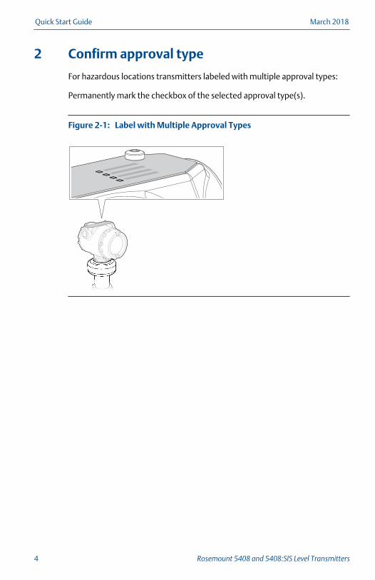
2 Confirm approval type
For hazardous locations transmitters labeled with multiple approval types:
Permanently mark the checkbox of the selected approval type(s).
Label with Multiple Approval TypesFigure 2-1:
Quick Start Guide March 2018
4 Rosemount 5408 and 5408:SIS Level Transmitters

3 Mount the transmitter
3.1 Flanged version
1. If applicable, assemble the segmented cone antenna (see Chapter 9).
2. Lower transmitter with antenna and flange into the nozzle.
Gasket
3. Tighten bolts and nuts with sufficient torque for the flange and gasketchoice.
4. Align the transmitter head (see Chapter 4).
3.2 Flanged version with air purge ring (option code PC1)
1. If applicable, assemble the segmented cone antenna (see Chapter 9).
March 2018 Quick Start Guide
Quick Start Guide 5
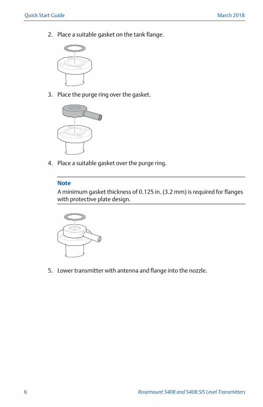
2. Place a suitable gasket on the tank flange.
3. Place the purge ring over the gasket.
4. Place a suitable gasket over the purge ring.
NoteA minimum gasket thickness of 0.125 in. (3.2 mm) is required for flangeswith protective plate design.
5. Lower transmitter with antenna and flange into the nozzle.
Quick Start Guide March 2018
6 Rosemount 5408 and 5408:SIS Level Transmitters

Antenna with air purge holes
6. Tighten bolts and nuts with sufficient torque for the flange and gasketchoice.
1.0 in. (25.5 mm)
7. Connect the air purging system. Use thread sealant or suitable gasketaccording to your site procedures.
March 2018 Quick Start Guide
Quick Start Guide 7

0.4 in. (10 mm)
or
G3/8-in.
Incoming Air Supply SpecificationTable 3-1:
Maximum pressure Recommended pressure
190 psi (13 bar) 100 to 115 psi (7 to 8 bar)
8. Align the transmitter head (see Chapter 4).
3.3 Threaded version, antenna diameter (D) < Threaddiameter (d)
3.3.1 Flanged tank connection
1. If applicable, assemble the segmented cone antenna (see Chapter 9).
2. Place a suitable gasket on the tank flange.
3. Place the customer supplied flange over the gasket.
Quick Start Guide March 2018
8 Rosemount 5408 and 5408:SIS Level Transmitters
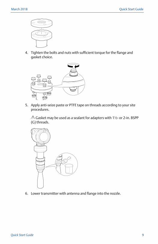
4. Tighten the bolts and nuts with sufficient torque for the flange andgasket choice.
5. Apply anti-seize paste or PTFE tape on threads according to your siteprocedures.
Gasket may be used as a sealant for adapters with 1½- or 2-in. BSPP(G) threads.
6. Lower transmitter with antenna and flange into the nozzle.
March 2018 Quick Start Guide
Quick Start Guide 9

Gasket (for 1½-in. and 2-in.
BSPP (G) threads only)
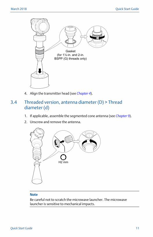
7. Align the transmitter head (see Chapter 4).
3.3.2 Threaded tank connection
1. If applicable, assemble the segmented cone antenna (see Chapter 9).
2. Apply anti-seize paste or PTFE tape on threads according to your siteprocedures.
Gasket may be used as a sealant for adapters with 1½- or 2-in. BSPP(G) threads.
3. Mount the transmitter on the tank.
Quick Start Guide March 2018
10 Rosemount 5408 and 5408:SIS Level Transmitters
Gasket (for 1½-in. and 2-in.
BSPP (G) threads only)
4. Align the transmitter head (see Chapter 4).
3.4 Threaded version, antenna diameter (D) > Threaddiameter (d)
1. If applicable, assemble the segmented cone antenna (see Chapter 9).
2. Unscrew and remove the antenna.
H2 mm
NoteBe careful not to scratch the microwave launcher. The microwavelauncher is sensitive to mechanical impacts.
March 2018 Quick Start Guide
Quick Start Guide 11
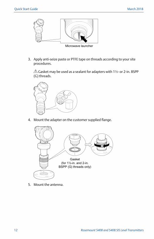
Microwave launcher
3. Apply anti-seize paste or PTFE tape on threads according to your siteprocedures.
Gasket may be used as a sealant for adapters with 1½- or 2-in. BSPP(G) threads.
4. Mount the adapter on the customer supplied flange.
Gasket (for 1½-in. and 2-in.
BSPP (G) threads only)
5. Mount the antenna.
Quick Start Guide March 2018
12 Rosemount 5408 and 5408:SIS Level Transmitters

H2 mm
38 mmTorque 250 in-lb (28 N-m)
Torque 5 in-lb (0.5 N-m)
NoteVisually inspect the microwave launcher for damage and dirt.
6. Lower transmitter with antenna and flange into the nozzle.
Gasket
7. Tighten the bolts and nuts with sufficient torque for the flange andgasket choice.
March 2018 Quick Start Guide
Quick Start Guide 13

8. Screw the adapter until it is properly tightened.
9. Align the transmitter head (see Chapter 4).
3.5 Bracket mounting
1. Mount the bracket to the pipe/wall.
On pipe:
Quick Start Guide March 2018
14 Rosemount 5408 and 5408:SIS Level Transmitters

4X
Horizontal pipe
Vertical pipe
On wall:
4X
2. Mount the holder to the bracket.
3. Unscrew and remove the antenna.
March 2018 Quick Start Guide
Quick Start Guide 15
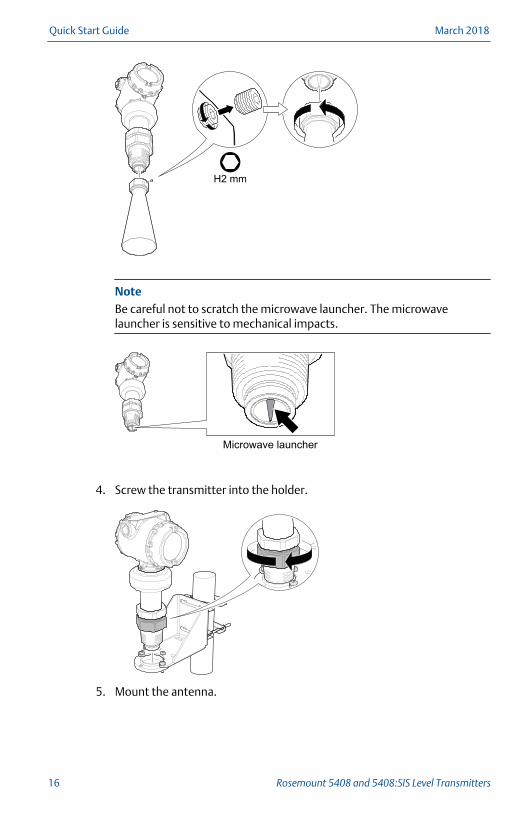
H2 mm
NoteBe careful not to scratch the microwave launcher. The microwavelauncher is sensitive to mechanical impacts.
Microwave launcher
4. Screw the transmitter into the holder.
5. Mount the antenna.
Quick Start Guide March 2018
16 Rosemount 5408 and 5408:SIS Level Transmitters
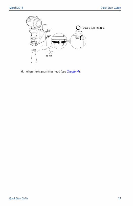
H2 mm
38 mm
Torque 5 in-lb (0.5 N-m)
6. Align the transmitter head (see Chapter 4).
March 2018 Quick Start Guide
Quick Start Guide 17
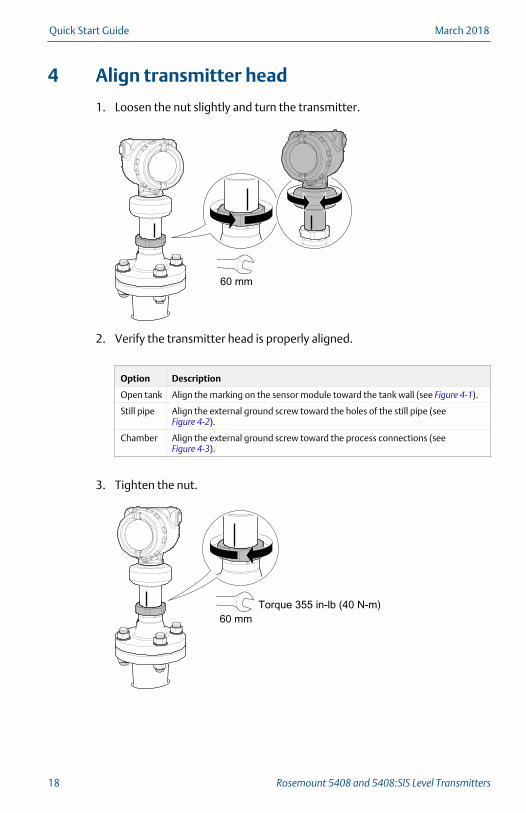
4 Align transmitter head
1. Loosen the nut slightly and turn the transmitter.
60 mm
2. Verify the transmitter head is properly aligned.
Option Description
Open tank Align the marking on the sensor module toward the tank wall (see Figure 4-1).
Still pipe Align the external ground screw toward the holes of the still pipe (see Figure 4-2).
Chamber Align the external ground screw toward the process connections (see Figure 4-3).
3. Tighten the nut.
60 mmTorque 355 in-lb (40 N-m)
Quick Start Guide March 2018
18 Rosemount 5408 and 5408:SIS Level Transmitters
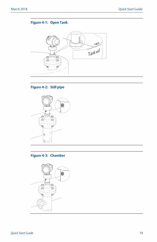
Open TankFigure 4-1:
Still pipeFigure 4-2:
ChamberFigure 4-3:
March 2018 Quick Start Guide
Quick Start Guide 19
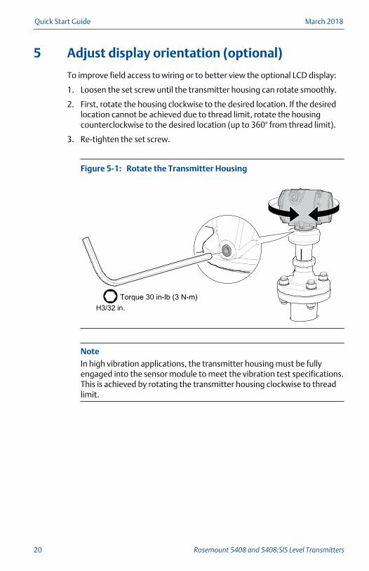
5 Adjust display orientation (optional)
To improve field access to wiring or to better view the optional LCD display:
1. Loosen the set screw until the transmitter housing can rotate smoothly.
2. First, rotate the housing clockwise to the desired location. If the desiredlocation cannot be achieved due to thread limit, rotate the housingcounterclockwise to the desired location (up to 360° from thread limit).
3. Re-tighten the set screw.
Rotate the Transmitter HousingFigure 5-1:
Torque 30 in-lb (3 N-m)H3/32 in.
NoteIn high vibration applications, the transmitter housing must be fullyengaged into the sensor module to meet the vibration test specifications.This is achieved by rotating the transmitter housing clockwise to threadlimit.
Quick Start Guide March 2018
20 Rosemount 5408 and 5408:SIS Level Transmitters
6 Prepare the electrical connections
6.1 Cable selection
Use 24-14 AWG wire. Twisted pairs and shielded wiring are recommended forenvironments with high EMI (electromagnetic interference).
The cables must be suitable for the supply voltage and approved for use inhazardous areas, where applicable. Two wires can be safely connected toeach terminal screw.
6.2 Cable gland/conduit
For explosion-proof/flameproof installations, only use cable glands orconduit entry devices certified explosion-proof or flameproof.
6.3 Power supply
The transmitter operates on 12-42.4 Vdc (12-30 Vdc in Intrinsically Safeinstallations) at the transmitter terminals.
6.4 Power consumption
Max. 1 W, current max. 23 mA
6.5 Load limitations
For HART® communication, a minimum loop resistance of 250 Ω is required.Maximum loop resistance is determined by the voltage level of the externalpower supply.
March 2018 Quick Start Guide
Quick Start Guide 21

Load LimitsFigure 6-1:
Maximum Loop Resistance = 43.5 * (External Power Supply Voltage - 12)
A. Loop Resistance (Ohms)B. External Power Supply Voltage (Vdc)
Quick Start Guide March 2018
22 Rosemount 5408 and 5408:SIS Level Transmitters
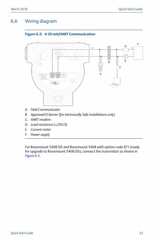
6.6 Wiring diagram
4-20 mA/HART CommunicationFigure 6-2:
1 2 3
4 5 6
7 8
0
9
A. Field CommunicatorB. Approved IS barrier (for Intrinsically Safe installations only)C. HART modemD. Load resistance (≥250 Ω)E. Current meterF. Power supply
For Rosemount 5408:SIS and Rosemount 5408 with option code EF1 (readyfor upgrade to Rosemount 5408:SIS), connect the transmitter as shown in Figure 6-3.
March 2018 Quick Start Guide
Quick Start Guide 23

4-20 mA/HART Communication - Terminal Block with TESTTerminal
Figure 6-3:
1 2 3
4 5 6
7 8
0
9
A. Field CommunicatorB. Approved IS barrier (for Intrinsically Safe installations only)C. HART modemD. Load resistance (≥250 Ω)E. Current meterF. Power supplyG. Blue plugH. TEST terminal
NoteBlue plug must only be disconnected during loop current measurementprocedure.
6.7 Grounding
Make sure grounding is done according to national and local electrical codes.Failure to do so may impair the protection provided by the equipment.
Transmitter housing
The most effective grounding method is direct connection to earth groundwith minimal impedance. There are two grounding screw connectionsprovided (see Figure 6-4).
Quick Start Guide March 2018
24 Rosemount 5408 and 5408:SIS Level Transmitters
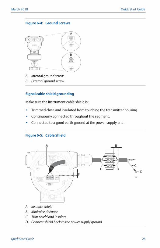
Ground ScrewsFigure 6-4:
A. Internal ground screwB. External ground screw
Signal cable shield grounding
Make sure the instrument cable shield is:
• Trimmed close and insulated from touching the transmitter housing.
• Continuously connected throughout the segment.
• Connected to a good earth ground at the power supply end.
Cable ShieldFigure 6-5:
A. Insulate shieldB. Minimize distanceC. Trim shield and insulateD. Connect shield back to the power supply ground
March 2018 Quick Start Guide
Quick Start Guide 25

7 Connect wiring and power up
1. Verify the power supply is disconnected.
2. Remove the cover.
3. Remove the plastic plugs.
4. Pull the cable through the cable gland/conduit. (1)
Identification of thread size and type
(1) Unless marked, the conduit/cable entries in the transmitter housing use a ½–14 NPT thread form.
Quick Start Guide March 2018
26 Rosemount 5408 and 5408:SIS Level Transmitters

5. Connect the cable wires (see Section 6.6).
Torque 7 in-lb (0.8 N-m)
6. Ensure proper grounding (see Section 6.7).
7. Tighten the cable gland.
PTFE tape or other sealant
NoteMake sure to arrange the wiring with a drip loop.
8. Seal any unused ports with the enclosed metal plug.
March 2018 Quick Start Guide
Quick Start Guide 27

PTFE tape or other sealant
9. Attach and tighten the covers. Make sure the covers are fully engaged.
a. Verify the cover jam screws are completely threaded into thehousing.
Cover jam screw(one per side)
H2.5 mm
b. Attach and tighten the covers.
c. Turn the jam screw counterclockwise until it contacts the cover.
Required for explosion-proof/flameproof installations only.
Quick Start Guide March 2018
28 Rosemount 5408 and 5408:SIS Level Transmitters

d. Turn the jam screw an additional ½ turn counterclockwise to securethe cover.
10. Connect the power supply.
NoteIt may take up to 15 seconds before the LCD display lights up.
March 2018 Quick Start Guide
Quick Start Guide 29
8 Configure transmitter using Guided Setup
8.1 Configuration tools
The transmitter can easily be configured using:
• Rosemount Radar Master Plus (running in the Instrument Inspector™
Application)
• Device Descriptor (DD) based systems, e.g. AMS Device Manager, 475Field Communicator, AMS Trex™ Device Communicator, and DeltaV™, orany other EDDL or enhanced-EDDL host
• Field Device Integration (FDI) based systems
Rosemount Radar Master Plus is the recommended tool for configuration.
8.2 Getting the latest FDI DevicePackage
The FDI Package or DD is typically installed together with the configurationtool.
The latest FDI Package is available at Emerson.com/RosemountRadarMasterPlus.
The latest DD is available at EmersonProcess.com/DeviceFiles.
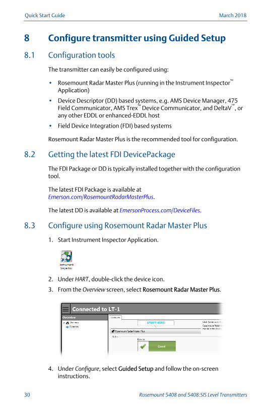
8.3 Configure using Rosemount Radar Master Plus
1. Start Instrument Inspector Application.
2. Under HART, double-click the device icon.
3. From the Overview screen, select Rosemount Radar Master Plus.
4. Under Configure, select Guided Setup and follow the on-screeninstructions.
Quick Start Guide March 2018
30 Rosemount 5408 and 5408:SIS Level Transmitters

8.4 Configure using AMS Device Manager
1. Start AMS Device Manager.
2. Select View > Device Connection View.
3. In the Device Connection View, double-click the HART modem icon.
4. Double-click the device icon.
5. Select Configure > Guided Setup.
6. Select Basic Setup and follow the on-screen instructions.
8.5 Configure using Field Communicator
1. Turn on the Field Communicator and connect to the device.
2. Select Configure > Guided Setup.
3. Select Basic Setup and follow the on-screen instructions.
8.6 Learn more
Visit Emerson.com/Rosemount to download the Rosemount 5408 and5408:SIS Reference Manual.
March 2018 Quick Start Guide
Quick Start Guide 31
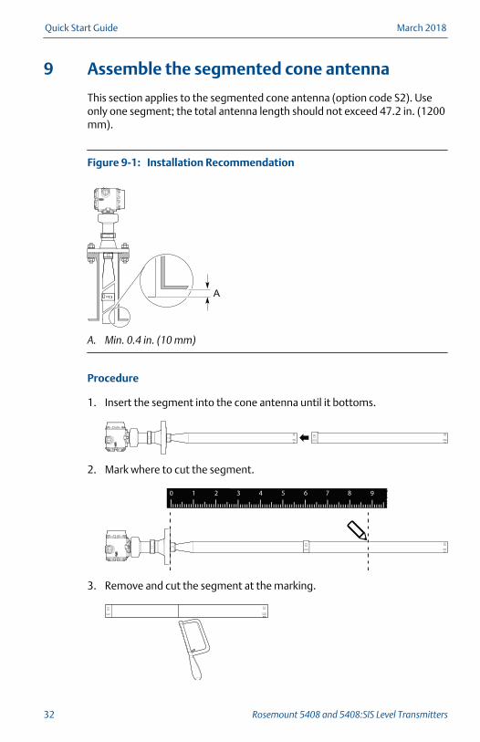
9 Assemble the segmented cone antenna
This section applies to the segmented cone antenna (option code S2). Useonly one segment; the total antenna length should not exceed 47.2 in. (1200mm).
Installation RecommendationFigure 9-1:
A. Min. 0.4 in. (10 mm)
Procedure
1. Insert the segment into the cone antenna until it bottoms.
2. Mark where to cut the segment.
1 2 3 4 5 6 7 80 9
3. Remove and cut the segment at the marking.
Quick Start Guide March 2018
32 Rosemount 5408 and 5408:SIS Level Transmitters

4. Remove any burrs.
5. Insert the segment into the cone antenna until it bottoms.
6. Secure the segment to the antenna.
1 2 3 4
7. Measure the Antenna Extension Length (L).
1 2 3 4 5 6 7 80 9
8. Update the transmitter configuration to the new Antenna ExtensionLength (L).
• Rosemount Radar Master Plus:
- Under Configure, select Level Setup > Antenna.
• AMS Device Manager and Field Communicator:
- Select Configure > Manual Setup > Level Setup > Antenna.
March 2018 Quick Start Guide
Quick Start Guide 33

Quick Start Guide March 2018
34 Rosemount 5408 and 5408:SIS Level Transmitters

March 2018 Quick Start Guide
Quick Start Guide 35

*00825-0100-4408*Quick Start Guide
00825-0100-4408, rev. ADMarch 2018
Manufactured byRosemount Tank Radar ABLayoutvägen 1S-435 33 MölnlyckeSweden+46 31 337 00 00+46 31 25 30 22
Global HeadquartersEmerson Automation Solutions6021 Innovation BlvdShakopee, MN 55379 USA+1 800 999 9307 or +1 952 906 8888+1 952 949 [email protected]
North America Regional OfficeEmerson Automation Solutions8200 Market Blvd.Chanhassen, MN 55317, USA+1 800 999 9307 or +1 952 906 8888+1 952 949 [email protected]
Latin America Regional OfficeEmerson Automation SolutionsSunrise, FL 33323, USAT +1 954 846 5030+1 954 846 [email protected]
Europe Regional OfficeEmerson Automation Solutions EuropeGmbHNeuhofstrasse 19a P.O. Box 1046CH 6340 BaarSwitzerlandT +41 (0) 41 768 6111+41 (0) 41 768 [email protected]
Asia Pacific Regional OfficeEmerson Automation Solutions1 Pandan CrescentSingapore 128461Republic of Singapore+65 6777 8211+65 6777 [email protected]
Middle East and Africa Regional OfficeEmerson Automation SolutionsEmerson FZE P.O. Box 17033Jebel Ali Free Zone - South 2Dubai, United Arab Emirates+971 4 8118100+971 4 [email protected]
©2018 Emerson. All rights reserved.
Emerson Terms and Conditions of Sale are availableupon request. The Emerson logo is a trademark andservice mark of Emerson Electric Co. Rosemount ismark of one of the Emerson family of companies.All other marks are the property of their respectiveowners.