qucm ge multilin 169 plus - niobrara r&d corporation · · 2004-12-30qucm ge multilin 169...
TRANSCRIPT
QUCM Multilin 169 PLUS Application Manual
QUCM GE Multilin 169 PLUSInstallation and Programming Manual
This Manual describes the QUCM application for interfacing GE Multilin 169 PLUS Relay devices to aModbus/TCP Ethernet system.
Effective: 24 September, 1999
Niobrara Research & Development CorporationP.O. Box 3418 Joplin, MO 64803 USA
Telephone: (800) 235-6723 or (417) 624-8918Facsimile: (417) 624-8920www.niobrara.com

POWERLOGIC, SY/MAX, and Square D are registered trademarks of Square D Com-pany.
GE, Multilin, 169 PLUS are trademarks of General Electric Company.
Subject to change without notice.
© Niobrara Research & Development Corporation 1999. All Rights Reserved.

3
Contents
1 Introduction .........................................................................................................................5
2 Installation .............................................................................................................................7
Module Installation .........................................................................................................7Software Installation .......................................................................................................7Serial Connections to the QUCM-SE .............................................................................7
Port 1 (and Port 2) to Multilin 169 PLUS Relays ...................................................7Port 1 to the Personal Computer .............................................................................8
Loading the Applications into the QUCM .....................................................................9
3 Operation .............................................................................................................................13
Register List .................................................................................................................13Slave Addresses ............................................................................................................19
4 Examples...............................................................................................................................23
Example 1 .....................................................................................................................23Example 2 .....................................................................................................................24
5 Web Server.........................................................................................................................27
Main Page .....................................................................................................................27Actual Data Page ..........................................................................................................30Setpoint Data Page .......................................................................................................31Statistics Page ...............................................................................................................34Configure Serial Port ....................................................................................................34
6 Troubleshooting..............................................................................................................37
Module Lights ..............................................................................................................37User Lights ...................................................................................................................37

4
Figures
Figure 2-1 DDC2I to Relay pinout .................................................................................................8
Figure 2-2 Layout with two Multilin Networks .............................................................................8
Figure 2-3 PC Connection to QUCM-SE serial port ......................................................................9
Figure 2-4 QUCM-SE to RS-232 PC DCE Port (9-pin) (MM1 Cable) .......................................9
Figure 4-1 Example with two Multilin Networks ........................................................................23
Figure 4-2 Example with one Multilin Network and one PNIM/Modbus Network ....................25
Figure 5-1 Main Page with Port 2 set for Multilin 169 Mode ......................................................28
Figure 5-2 Main Page with Port 2 set for PNIM/Modbus Mode ..................................................29
Figure 5-3 Web Server Actual Data Page ....................................................................................30
Figure 5-4 Setpoint Data Page ......................................................................................................31
Figure 5-5 Enter Password Page ...................................................................................................32
Figure 5-6 Sample Edit of Setpoints Page ....................................................................................33
Figure 5-7 Statistics Web Page.....................................................................................................34
Figure 5-8 Serial Port Configuration Page ...................................................................................35
Tables
Table 3-1 Holding Register List ...................................................................................................14
Table 3-2 Motor Current Status ....................................................................................................18
Table 3-3 Motor Alarm Status ......................................................................................................19
Table 3-4 Motor Trip Status .........................................................................................................19
Table 3-5 Destination Index Slave Table .....................................................................................20
Table 3-6 PNIM/Modbus Destination Index Slave Table ............................................................21
Table 4-1 SMS Index List ............................................................................................................24
Table 4-2 SMS Index List ............................................................................................................25
Table 6-1 Module Lights ..............................................................................................................37
Table 6-2 User Light Definitions .................................................................................................38

QUCM Multilin 169 PLUS Application Manual 1 Introduction 5
1
Introduction
The Niobrara QUCM is a TSX Quantum® compatible module that is capable of run-ning multiple applications for performing communication translations between serialprotocols. This document covers an application that places GE Multilin 169 Plus Re-lay devices on a Modbus/TCP Ethernet network. The Multilin 169 Plus Motor Man-agement Relay does not support the standard Modbus RTU serial protocol. ThisQUCM application polls networks of these relays in their native protocol and providesan interface for Modbus/TCP Ethernet devices so the data may be accessed as stan-dard Modbus Holding Registers (4x) These devices may then be accessed byModbus/TCP Clients such as Square D POWERLOGIC® System Manager Software.
The application, "app1.qcm" is compiled and loaded into Application 1 of the QUCM-SE with the Auto-Start feature enabled for stand-alone operation. The application in-cludes multiple threads for simultaneously servicing both serial ports and the Ethernetport. Threads 1 and 2 provide the interface for up to two Multilin 169 PLUS Rely net-works on QUCM Ports 1 and 2. Threads 3, 4, 5, 6, and 7 provide Modbus/TCP Serv-ers for emulating the Multilin data as Modbus Holding Registers (4x) over Ethernet. Thread 8 provides a web server for quick reference of relay data using a commonbrowser.
A Modicon two (or more) slot Quantum rack and appropriate Quantum power supplyis needed for mounting the QUCM-SE.
Port 1 of the QUCM is always configured for a Multilin 169 network and will supportup to 20 relays. Port 2 may be configured for a Multilin network and also support upto 20 relays or it may also be configured for a combination PNIM/Modbus RTU net-work and support up to 32 PNIM and/or Modbus RTU slaves.
The Multilin relays may be connected to a QUCM port using a Niobrara DDC2I Iso-lated RS-232<>RS-485 converter. An NR&D MM0 cable is used to connect the RJ45port on the QUCM-SE to the RJ45 port on the DDC2I. The DDC2I is powered by theQUCM-SE. All six DIP switches on the DDC2I must be ON to provide 2-wire,multidrop RS-485 with termination and biasing. The DDC2I and MM0 are also usedfor connecting PNIM or Modbus devices to the QUCM.

6 Introduction 1 QUCM Multilin 169 PLUS Application Manual
The Multilin relays must be addressed in the range of 1 to 20 inclusive on each net-work. The incoming Destination Index value will be used for selecting the targetrelay data where Index 1 selects the data for unit 1 on Port 1 and Index 40 selects thedata for unit 20 on Port 2. The QUCM-SE will support up to five simultaneousModbus/TCP clients for access to the relay data.
If Port 2 is set to PNIM/Modbus mode then Destination Index accesses of 21 through40 will return error messages and the PNIM/Modbus devices are accessed as Indexvalues 101 through 132 inclusive.

QUCM Multilin 169 PLUS Application Manual 2 Installation 7
2
Installation
Module Installation1 Mount the QUCM in an available slot in the register rack. Secure the screw at the
bottom of the module.
Software InstallationThe application files for the QUCM are included in the M169.ZIP file. This file mustbe unzipped using PKUNZIP.EXE. A copy of PKUNZIP is included on the standardNR&D software disk and is also available at www.niobrara.com. The latest version ofthe M169.ZIP file is located at
ftp.niobrara.com/qucm/multilin/m169.zip
The latest version of this document in pdf format is located at:
ftp.niobrara.com/qucm/multilin/m169.pdf
Serial Connections to the QUCM-SE
Port 1 (and Port 2) to Multilin 169 PLUS Relays
The serial ports of the QUCM-SE are RS-232 while the Multilin relay is 2-wire RS-485. The Niobrara DDC2I converter with an MM0 cable is ideal for this connectionsince it includes an RJ45 RS-232 connection for the QUCM-SE and an optically iso-lated RS-485 port with removable screw terminals. The cable pinout from the DDC2Ito the Multilin meters is described in Figure 2-1. It is advised to add a 220 ohm termi-nating resistor between A and B on the last relay in the network chain.
The Multilin relays will be configured so their "Slave Address" is within the range of01 through 20 for each network attached to the QUCM-SE. Figure 2-2 shows two net-works of relays connected to a single QUCM-SE.

8 Installation 2 QUCM Multilin 169 PLUS Application Manual
Figure 2-1 DDC2I to Relay pinout
Figure 2-2 Layout with two Multilin Networks
Port 1 to the Personal Computer
A physical connection must be made from the personal computer to the QUCM in or-der to configure the Ethernet parameters of the QUCM-SE. This link may be a serialconnection from a COM port on the personal computer to the RS-232 port on theQUCM-SE. The Niobrara MM1 cable may be used for this connection. This cablepinout is shown in Figure 2-4.
DDC2I Multilin 169 Plus Multilin 169 Plus
TX+ 47 (A) 47 (A)
TX- 46 (B) 46 (B)
MM0 Cable
140QUCMNiobrara
ActiveReadyRun
ColLnkTXERXE
12345
RN1TX1RX1
6789
10RN2TX2RX2
Fault
169 169 169DDC2IPower RxTxTxEN
RS422/RS485Rx- Rx+ Tx- Tx+
RS422/RS485
9V-24V- +
RS2325V IN
4 WIRE/2WIRE
MASTER/SLAVEOFF/ON TERMINATIONOFF/ON BIAS
2-Wire Cable
Add = 01 Add = 02 Add = 20
MM0 Cable
169 169 169DDC2IPower RxTxTxEN
RS422/RS485Rx- Rx+ Tx- Tx+
RS422/RS485
9V-24V- +
RS2325V IN
4 WIRE/2WIRE
MASTER/SLAVEOFF/ON TERMINATIONOFF/ON BIAS
2-Wire Cable
Add = 01 Add = 02 Add = 20

QUCM Multilin 169 PLUS Application Manual 2 Installation 9
Figure 2-3 PC Connection to QUCM-SE serial port
Figure 2-4 QUCM-SE to RS-232 PC DCE Port (9-pin) (MM1 Cable)
Loading the Applications into the QUCMThe QUCM is rapidly evolving so be sure to upgrade the firmware in the module be-fore loading the latest version of APP1.QCC. Most likely the QCOMPILE.EXE hasbeen updated, so be sure to use the newest version. Firmware upload is as follows:
1 Remove the module form the rack.
2 Move the RUN/LOAD switch on the back of the module to LOAD.
3 Replace the module in the rack and apply power.
4 Only the 3 light should be on. (The Link and RX E-net lights may be on if theE-net port is connected and there is traffic.)
5 Connect the PC to QUCM Port 1 with a MM1 cable.
6 From the command line enter> fwload qucmtcp.fwl com1:
MM1 Cable
PC
140QUCMNiobrara
ActiveReadyRun
ColLnkTXERXE
12345
RN1TX1RX1
6789
10RN2TX2RX2
Fault
RJ45 DE9S (female)
3 2
4 3
5 5
6 4
7 6
7
8

10 Installation 2 QUCM Multilin 169 PLUS Application Manual
Be sure to have the colon after the PC’s com port name. The download will onlytake a few minutes and will inform when finished.
7 Remove the module from the rack and change the switch back to RUN.
8 It is a good idea to press the RESET button after a firmware change.
It is recommended to use the Ethernet capabilities of QLOAD to load APP1.QCC intothe QUCM. Set up the IP parameters of the module by the following method:
1 Move Switch 1 to Halt.
2 Connect the PC to QUCM Port 1 with a MM1 cable.
3 From the command line enter>zapreg32 com1:9600,e,8,1 255 -b
This will start zapreg32 in Modbus RTU mode to slave address 255. Use the ar-row and Page Up/Down keys to move to register 46. The IP parameters are shownbelow for a unit with the IP = 206.223.51.161 subnet Mask = 255.255.255.0, De-fault Gate = 206.223.51.1, Modbus/TCP port number = 503, Telnet Port number =23:
Register DescriptionExample (decimal)-------- ---------- ---------------------46 IP MSByte 20647 IP 22348 IP 5149 IP LSByte 16150 SN Mask 25551 SN Mask 25552 SN Mask 25553 SN Mask 054 Def. Gate 20655 Def. Gate 22356 Def. Gate 5157 Def. Gate 158 TCP Control 7 (leave this at 7)59 Reserved 060 Reserved 061 Reserved 062 TCP backstep 100 (leave this at 100)63 Modbus Port 503 (this defaults to 502)64 Telnet Port 23 (this defaults to 23)65 Quiet Timer 900 (leave this at 900)66 Clients -1 (leave this at -1)
4 After entering the IP parameters, attempt to ping the module to verify the settings. > ping 206.223.51.161
5 Verify a connection to the internal Modbus/TCP server with zapreg32. > zapreg32 206.223.51.161:503 255
Should connect to the QUCM on port 503 with Destination index 255.
6 Load the APP1 file with qload. > qload 1 app1 206.223.51.161:503 -a

QUCM Multilin 169 PLUS Application Manual 2 Installation 11
Will load the file into application 1’s flash and set the program to automaticallystart on power-up.
7 Place Switch 1 in RUN. The RN1 light should come on.
Connect the DDC2I(s) to QUCM-SE Port(s) 1 (and/or 2). The QUCM-SE will beginattempting to communicate with the attached devices.


QUCM Multilin 169 PLUS Application Manual 3 Operation 13
3
Operation
The Multilin 169 Plus relay network may consist of up to 20 slaves. The QUCM ap-plication supports up to two full networks and automatically determines which Mul-tilin units are active on each serial port. The application is written in such a manner tosearch for non-responding relays periodically while having a minimum impact on thepolling of the known active devices.
The known active devices on each port are continuously polled to retrieve their "Ac-tual Values" and occasionally polled to retrieve their "Setpoint Values". These valuesare stored internally in the QUCM for access by Modbus/TCP Clients or the built-inweb server. It takes three messages to each relay to gather all of the "Actual Data"and four messages to gather the "Setpoint Data" for each relay. The application guar-antees that the Modbus/TCP (and web server) data polled on a relay will be from asingle series of polls of the device.
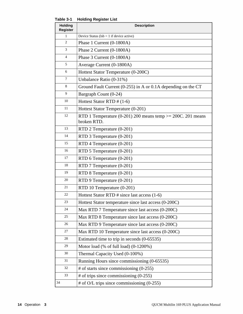
Register ListTable 3-1 provides the description of the 193 Holding Registers assigned for each pos-sible slave.
NOTE: All reads of registers > 193 will receive x8000 (hex) for the reply.
NOTE: The Modbus/TCP server supports opcode 03 Holding Register reads, opcode100 Random Access Holding Register Reads, and optionally opcode 16 Holding Reg-ister Writes for the Setpoint Data.
14 Operation 3 QUCM Multilin 169 PLUS Application Manual
Table 3-1 Holding Register List
HoldingRegister
Description
1 Device Status (lsb = 1 if device active)
2 Phase 1 Current (0-1800A)3 Phase 2 Current (0-1800A)4 Phase 3 Current (0-1800A)5 Average Current (0-1800A)6 Hottest Stator Temperature (0-200C)7 Unbalance Ratio (0-31%)8 Ground Fault Current (0-255) in A or 0.1A depending on the CT9 Bargraph Count (0-24)10 Hottest Stator RTD # (1-6)11 Hottest Stator Temperature (0-201)12 RTD 1 Temperature (0-201) 200 means temp >= 200C. 201 means
broken RTD.13 RTD 2 Temperature (0-201)14 RTD 3 Temperature (0-201)15 RTD 4 Temperature (0-201)16 RTD 5 Temperature (0-201)17 RTD 6 Temperature (0-201)18 RTD 7 Temperature (0-201)19 RTD 8 Temperature (0-201)20 RTD 9 Temperature (0-201)21 RTD 10 Temperature (0-201)22 Hottest Stator RTD # since last access (1-6)23 Hottest Stator temperature since last access (0-200C)24 Max RTD 7 Temperature since last access (0-200C)25 Max RTD 8 Temperature since last access (0-200C)26 Max RTD 9 Temperature since last access (0-200C)27 Max RTD 10 Temperature since last access (0-200C)28 Estimated time to trip in seconds (0-65535)29 Motor load (% of full load) (0-1200%)30 Thermal Capacity Used (0-100%)31 Running Hours since commissioning (0-65535)32 # of starts since commissioning (0-255)33 # of trips since commissioning (0-255)
34 # of O/L trips since commissioning (0-255)

QUCM Multilin 169 PLUS Application Manual 3 Operation 15
35 # of rapid trips since commissioning (0-255)36 # of U/B trips since commissioning (0-255)37 # of G/F trips since commissioning (0-255)38 # of RTD trips since commissioning (0-255)39 # of start trips since commissioning (0-255)40 # of S/C trips since commissioning (0-255)41 Lockout Time (0-60 minutes)42 Pre-trip average current (0-1800A)43 Pre-trip unbalance ratio (0-31%)44 Pre-trip Ground fault current (0-255)45 Pre-trip maximum stator # (1-6)46 Pre-trip maximum stator temperature (0-200C)47 Learned avg. Istart (0-1800A)48 Learned last Istart (0-1800A)49 Learned K factor (3-25)50 Learned running cool time (5-60 minutes)51 Learned stopped cool time (5-60 minutes)52 Learned acceleration time (0-255 in 0.5sec)53 Learned start capacity (10-90%)54 Communication status (0-255)55 Motor Current status (0-3) (See Table 3-2)56 Motor Alarm Status (0-65535) (See Table 3-3)57 Motor Trip Status (0-65535) (See Table 3-4)58 Setpoint Status byte 1 (0-255)59 Setpoint Status byte 2 (0-255)60 Setpoint Status byte 3 (0-255)61 LED Data bitmap62 TRPMSGCONT63 TIMEOUT64 spare65 spare (END of ACTUAL DATA)66 Phase C.T. Ratio (START of SETPOINT DATA) (20 to 1500)
67 Motor Full Load Current (10 to 1500A)
68 Acceleration Time (x 0.5 Seconds) (1 to 251)
69 Starts Per Hour (1 to 6)
70 Unbalance Alarm Level % (4 to 31)
71 Unbalance Alarm Delay Seconds (3 to 255)
72 Unbalance Trip Level % (4 to 31)

16 Operation 3 QUCM Multilin 169 PLUS Application Manual
73 Unbalance Trip Delay Seconds (3 to 255)
74 Ground Fault C.T. Ratio x 50 (1 to 5)
75 Ground Fault Alarm Level (1 to 11)
76 Ground Fault Alarm Delay Seconds (1 to 255)
77 Ground Fault Trip Level (1 to 11)
78 Ground Fault Trip Delay x 0.5 Seconds (0 to 41)
79 Undercurrent Level Amps (1 to 1001)
80 Undercurrent Delay Seconds (1 to 255)
81 Rapid Trip Level x 1.5 FLC (3 to 10)
82 Rapid Trip Delay x 0.5 Seconds (1 to 250)
83 Short Circuit Level x 0.5 FLC (3 to 10)
84 Short Circuit Delay x 0.5 Seconds (0 to 41)
85 Immediate Overload x 0.001 FLC (101 to 151)
86 Phase C.T. Secondary (9 to 10)
87 Number of Stator RTDs (0 to 6)
88 RTD 1 Alarm Level C (0 to 201)
89 RTD 1 Trip Level C (0 to 201)
90 RTD 7 Alarm Level C (0 to 201)
91 RTD 7 Trip Level C (0 to 201)
92 RTD 8 Alarm Level C (0 to 201)
93 RTD 8 Trip Level C (0 to 201)
94 RTD 9 Alarm Level C (0 to 201)
95 RTD 9 Trip Level C (0 to 201)
96 RTD 10 Alarm Level C (0 to 201)
97 RTD 10 Trip Level C (0 to 201)
98 Selected Overload Curve (1 to 8)
99 Trip Time at 1.05 x FLC (1 to 12000)
100 Trip Time at 1.10 x FLC (1 to 12000)
101 Trip Time at 1.20 x FLC (1 to 12000)
102 Trip Time at 1.30 x FLC (1 to 12000)
103 Trip Time at 1.40 x FLC (1 to 12000)
104 Trip Time at 1.50 x FLC (1 to 2000)
105 Trip Time at 1.75 x FLC (1 to 2000)
106 Trip Time at 2.00 x FLC (1 to 2000)
107 Trip Time at 2.25 x FLC (1 to 2000)
108 Trip Time at 2.50 x FLC (1 to 2000)
109 Trip Time at 2.75 x FLC (1 to 2000)
110 Trip Time at 3.00 x FLC (1 to 2000)
111 Trip Time at 3.50 x FLC (1 to 2000)
112 Trip Time at 4.00 x FLC (1 to 2000)
113 Trip Time at 4.50 x FLC (1 to 2000)
114 Trip Time at 5.00 x FLC (1 to 2000)
115 Trip Time at 5.50 x FLC (1 to 2000)
116 Trip Time at 6.00 x FLC (1 to 2000)

QUCM Multilin 169 PLUS Application Manual 3 Operation 17
117 Trip Time at 6.50 x FLC (1 to 2000)
118 Trip Time at 7.00 x FLC (1 to 2000)
119 Trip Time at 7.50 x FLC (1 to 2000)
120 Trip Time at 8.00 x FLC (1 to 2000)
121 Overload Trip Assignment (16 to 18)
122 Unbalance Trip Assignment (16 to 18)
123 Short Circuit Trip Assignment (16 to 18)
124 Rapid Trip Assignment (16 to 18)
125 Stator Trip Assignment (16 to 18)
126 RTD Trip Assignment (16 to 18)
127 Ground Fault Trip Assignment (16 to 18)
128 Acceleration Trip Assignment (16 to 18)
129 Phase Reversal Trip Assignment (16 to 18)
130 Starts Per Hour Trip Assignment (16 to 18)
131 Speed Switch Trip Assignment (16 to 18)
132 Differential Input Trip Assignment (16 to 18)
133 Single Phase Trip Assignment (16 to 18)
134 Spare Input Trip Assignment (16 to 18)
135 Start Trip Assignment (16 to 18)
136 Overload Warning Assignment (13 to 16)
137 Ground Fault Alarm Assignment (13 to 16)
138 Unbalance Alarm Assignment (13 to 16)
139 Undercurrent Alarm Assignment (13 to 16)
140 Stator RTD Alarm Assignment (13 to 16)
141 RTD Alarm Assignment (13 to 16)
142 No Sensor Alarm Assignment (13 to 16)
143 Self-Test Assignment (13 to 16)
144 Spare Input Alarm Assignment (13 to 16)
145 Default Display Line Code (1 to 40)
146 Default Display Page Code (1 to 10)
147 RTD Bias Minimum Value C (0 to 200)
148 RTD Bias Maximum Value C (0 to 200)
149 Default Running Cool Time Minutes (1 to 45)
150 Default Stopped Cool Time Minutes (5 to 65)
151 D/A Output Parameter (45 to 48)
152 Alarm Relay Latchcode (1 to 4)
153 Relay Failsafe Code (1 to 8)
154 Speed Switch Delay x 0.5 Seconds (1 to 250)
155 Spare Input Alarm Delay Seconds (1 to 255)
156 Spare Input Trip Delay Seconds (1 to 255)
157 Default K (1 to 20)
158 Slave Function Byte 1 (0 to 255)
159 Slave Function Byte 2 (0 to 255)
160 Slave Function Byte 3 (0 to 255)

18 Operation 3 QUCM Multilin 169 PLUS Application Manual
Table 3-2 Motor Current Status
161 Slave Function Byte 4 (0 to 255)
162 Slave Function Byte 5 (0 to 255)
163 Slave Function Byte 6 (0 to 255)
164 User Relay Force Code (x1B to x20) hex
165 User RTD Force Code (0 to 10)
166 User RTD Force Code Value C (0 to 201)
167 User Analog Force Code (x21 to x24) hex
168 Time between last update of Actual Values Seconds
169 Unused
170 Age of this Actual Values Data Seconds
171 Time between last update of Setpoint Values Seconds
172 Age of this Setpoint Values Data Seconds
173 Number of Stator RTDs (0-6)
174 RTD 1 Alarm Level C (0 to 201)
175 RTD 1 Trip Level C (0 to 201)
176 RTD 2 Alarm Level C (0 to 201)
177 RTD 2 Trip Level C (0 to 201)
178 RTD 3 Alarm Level C (0 to 201)
179 RTD 3 Trip Level C (0 to 201)
180 RTD 4 Alarm Level C (0 to 201)
181 RTD 4 Trip Level C (0 to 201)
182 RTD 5 Alarm Level C (0 to 201)
183 RTD 5 Trip Level C (0 to 201)
184 RTD 6 Alarm Level C (0 to 201)
185 RTD 6 Trip Level C (0 to 201)
186 RTD 7 Alarm Level C (0 to 201)
187 RTD 7 Trip Level C (0 to 201)
188 RTD 8 Alarm Level C (0 to 201)
189 RTD 8 Trip Level C (0 to 201)
190 RTD 9 Alarm Level C (0 to 201)
191 RTD 9 Trip Level C (0 to 201)
192 RTD 10 Alarm Level C (0 to 201)
193 RTD 10 Trip Level C (0 to 201)
Status Value Meaning
0 Motor Stopped (Iavg < 10% FLC)
1 Motor Running Normal (Iavg < 1FLC)
2 Motor in O/L (Iavg > 1FLC)
3 Motor Starting

QUCM Multilin 169 PLUS Application Manual 3 Operation 19
Table 3-3 Motor Alarm Status
Table 3-4 Motor Trip Status
Slave AddressesThe data from the possible 40 slaves is accessed via Modbus/TCP by the DestinationIndex field of the Modbus/TCP message. Table 3-5 displays the 40 supported Desti-nation Index values and the associated Relay.
Alarm Bit Meaning if bit = 1
16 (lsb) Immediate O/L Warning
15 Ground Fault Alarm
14 Unbalance Alarm
13 Undercurrent Alarm
12 Stator RTD Alarm
11 Bearing RTD Alarm
10 Broken Sensor Alarm
9 Self-Test Failure
8 Spare Input Alarm
7 Undefined
6 Undefined
5 Undefined
4 Undefined
3 Undefined
2 Undefined
1 (msb) Undefined
Alarm Bit Meaning if bit = 1
16 (lsb) Overload Trip
15 Unbalance Trip
14 Short Circuit Trip
13 Rapid Trip
12 Stator RTD Trip
11 RTD Trip
10 Ground Fault Trip
9 Acceleration Time Trip
8 Phase Reversal Trip
7 Starts Per Hour Trip
6 Speed Switch Trip
5 Differential Input Trip
4 Single Phase Trip
3 Spare Input Trip
2 Start Inhibit Trip
1 (msb) Undefined

20 Operation 3 QUCM Multilin 169 PLUS Application Manual
NOTE: Attempts to access data from slaves that are not responding will result in aModbus/TCP exception code x0B. If Port 2 is configured for Multilin 169 mode thenattempting to access devices > 40 will also result in an exception code x0B response.
Table 3-5 Destination Index Slave Table
If Port 2 is set for PNIM/Modbus then accesses to Indexes 21 through 40 will result inerror x0B replies and accesses of Indexes 101 though 132 will result in messages be-ing routed out Port 2 in either the PNIM or Modbus RTU protocol. The QUCM willattempt one protocol and then the other until it determines the type of device at agiven slave address.
The supported slave addresses for PNIM and/or Modbus RTU slaves is shown in Ta-ble 3-6. All PNIM and/or Modbus RTU slaves must be set to the same baud rate andparity.
Index QUCMPort
Slave Index QUCMPort
Slave
1 1 1 21 2 1
2 1 2 22 2 2
3 1 3 23 2 3
4 1 4 24 2 4
5 1 5 25 2 5
6 1 6 26 2 6
7 1 7 27 2 7
8 1 8 28 2 8
9 1 9 29 2 9
10 1 10 30 2 10
11 1 11 31 2 11
12 1 12 32 2 12
13 1 13 33 2 13
14 1 14 34 2 14
15 1 15 35 2 15
16 1 16 36 2 16
17 1 17 37 2 17
18 1 18 38 2 18
19 1 19 39 2 19
20 1 20 40 2 20

QUCM Multilin 169 PLUS Application Manual 3 Operation 21
Table 3-6 PNIM/Modbus Destination Index Slave Table
Index QUCMPort
Slave Index QUCMPort
Slave
101 2 1 117 2 17
102 2 2 118 2 18
103 2 3 119 2 19
104 2 4 120 2 20
105 2 5 121 2 21
106 2 6 122 2 22
107 2 7 123 2 23
108 2 8 124 2 24
109 2 9 125 2 25
110 2 10 126 2 26
111 2 11 127 2 27
112 2 12 128 2 28
113 2 13 129 2 29
114 2 14 130 2 30
115 2 15 131 2 31
116 2 16 132 2 32


QUCM Multilin 169 PLUS Application Manual 4 Examples 23
4
Examples
Example 1Figure 4-1 displays an example Multilin system with a QUCM-SE and two networksof Multilin 169 Plus relays. Port 1 of the QUCM-SE has a NR&D DDC2I RS-232<>RS-485 converter connected with an MM0 cable to three 169 relays. The relaysare set to Slave Address 01, 02, and 03. QUCM Port 2 also has three 169 meters set toSlave Address 01, 12, and 19.
Figure 4-1 Example with two Multilin Networks
MM0 Cable
140QUCMNiobrara
ActiveReadyRun
ColLnkTXERXE
12345
RN1TX1RX1
6789
10RN2TX2RX2
Fault
169 169 169DDC2IPower RxTxTxEN
RS422/RS485Rx- Rx+ Tx- Tx+
RS422/RS485
9V-24V- +
RS2325V IN
4 WIRE/2WIRE
MASTER/SLAVEOFF/ON TERMINATIONOFF/ON BIAS
2-Wire Cable
Add = 01 Add = 02 Add = 03
MM0 Cable
169 169 169DDC2IPower RxTxTxEN
RS422/RS485Rx- Rx+ Tx- Tx+
RS422/RS485
9V-24V- +
RS2325V IN
4 WIRE/2WIRE
MASTER/SLAVEOFF/ON TERMINATIONOFF/ON BIAS
2-Wire Cable
Add = 01 Add = 12 Add = 19SMS Server
Hub
Ethernet

24 Examples 4 QUCM Multilin 169 PLUS Application Manual
The QUCM-SE is connected to an Ethernet Hub via a 10BaseT cable. Also on theEthernet network is an SMS-3000 system that needs data from the 169 Relays.
SMS may be configured where the relays are a "Powerlogic Compatible" or "ModbusCompatible". The QUCM application will accept normal Modbus/TCP HoldingReads (opcode 03) or Powerlogic Random Reads (opcode 100). The Index values areshown in Table 4-1.
Table 4-1 SMS Index List
Example 2Figure 4-2 displays an example Multilin system with a QUCM-SE with one networkof Multilin 169 Plus relays and a second network with a POWERLOGIC CM2000meter, a Multilin 269 relay, and a Modicon Momentum PLC.
Port 1 of the QUCM-SE has a NR&D DDC2I RS-232<>RS-485 converter connectedwith an MM0 cable to the three 169 relays. The relays are set to Slave Address 01,02, and 03.
QUCM Port 2 also has a NR&D DDC2I RS-232<>RS-485 converter connected withan MM0 cable its RS-485 devices. The CM2000 communicates with the PNIM proto-col and is set for Slave Address 01. The Multilin 269 relay and Momentum PLC com-municate with the Modbus RTU protocol and are set for Slave Addresses 2, and 3. The Multilin Relay only has a 2-wire RS-485 connection so the CM and PLC are alsowired for 2-wire by simply jumpering the IN+ to OUT+ and IN- to OUT-.
The QUCM-SE is connected to an Ethernet Hub via a 10BaseT cable. Also on theEthernet network is an SMS-3000 system that needs data from all of the Devices.
Index Target Relay
1 Port 1, Relay 1
2 Port 1, Relay 2
3 Port 1, Relay 3
21 Port 2, Relay 1
32 Port 2, Relay 12
39 Port 2, Relay 19

QUCM Multilin 169 PLUS Application Manual 4 Examples 25
Figure 4-2 Example with one Multilin Network and one PNIM/Modbus Network
SMS may be configured where the 169 relays are a "Powerlogic Compatible" or"Modbus Compatible". The CM2000 is configured as a CM2000. The 269 Relay andPLC are configured as "Modbus Compatible". The Index values are shown in Table4-2.
Table 4-2 SMS Index List
The QUCM application will pass all incoming Modbus/TCP messages routed toModbus devices on port 2. Thus the PLC may be programmed with Modsoft, Con-cept, or Proworks Nxt by selecting Modbus/TCP as the connection type with the IPaddress of the QUCM and Index 103. The newer versions of the Multilin supportsoftware may also use Modbus/TCP to access the 269 relay for setup.
MM0 Cable
140QUCMNiobrara
ActiveReadyRun
ColLnkTXERXE
12345
RN1TX1RX1
6789
10RN2TX2RX2
Fault
169 169 169DDC2IPower RxTxTxEN
RS422/RS485Rx- Rx+ Tx- Tx+
RS422/RS485
9V-24V- +
RS2325V IN
4 WIRE/2WIRE
MASTER/SLAVEOFF/ON TERMINATIONOFF/ON BIAS
2-Wire Cable
Add = 01 Add = 02 Add = 03
MM0 Cable
PowerLogic 269DDC2IPower RxTxTxEN
RS422/RS485Rx- Rx+ Tx- Tx+
RS422/RS485
9V-24V- +
RS2325V IN
4 WIRE/2WIRE
MASTER/SLAVEOFF/ON TERMINATIONOFF/ON BIAS
2-Wire Cable
Add = 01 Add = 02
Add = 03SMS Server
Hub
Ethernet
Index Target Relay
1 Port 1, Relay 1
2 Port 1, Relay 2
3 Port 1, Relay 3
101 Port 2, CM2000
102 Port 2, Relay 269
103 Port 2, PLC


QUCM Multilin 169 PLUS Application Manual 5 Web Server 27
5
Web Server
Main PageThe Main page dynamically adjusts for two different views based on the setup config-ured for QUCM Port 2. When Port 2 is configured for Multilin 169 Mode the Mainpage shows a table with elements for the 40 possible relays. If a relay is not respond-ing to queries from the QUCM then the table entry will have a gray background anddisplay the text "Offline". If the relay is responding to queries then the cell will dis-play "Online" along with a short description of the status of the relay. The Onlinemessage is a hypertext link that will display the "Actual" data for that relay. If the re-lay is not tripped then the cell will display the state of the motor.
• Motor Stopped• Motor Running Normal• Motor in O/L• Motor StartingIf the Relay is tripped then the cell background will change to yellow and one or moreof the following messages will be displayed.
• Overload Trip• Unbalance Trip• Short Circuit Trip• Rapid Trip• Stator RTD Trip• RTD Trip• Ground Fault TripFigure 5-3 shows an example page with Port 2 set for Multilin 196 mode with Relay#30 online and its motor stopped.
At the bottom of the Main page are links to Niobrara’s WWW site, Statistics on thisQUCM, and a page for configuring Port 2 of this QUCM.


QUCM Multilin 169 PLUS Application Manual 6 Troubleshooting 37
6
Troubleshooting
Module LightsThe QUCM-SE has several lights that indicate the status of the module. Table 6-1shows the meanings of these lights.
Table 6-1 Module Lights
User LightsThe QUCM-SE has 10 application driven lights numbered 1-10. The meaning ofthese lights while the APP1 program is running is shown in Table 6-2.
Light Meaning
Fault The module has a catastrophic fault.. Call the factory.
Active This light will be on if the module is in a traffic copped slot in a Quantum PLCsystem and the PLC is in RUN.
Ready This light should always be on (as long as it isn’t in firmware load).
Run This light will be on if the module is in a traffic copped slot in a Quantum PLCsystem and the PLC is in RUN.
Col Comes on when an Ethernet collision occurs.
Lnk Is on when LINK is established on the 10BaseT port.
TXE Comes on when the module is transmitting on the Ethernet port.
RXE Comes on when the module is receiving on the Ethernet port.
RN1 This light should be on to indicate app1 is running.
TX1 Comes on when the module is transmitting on serial port 1.
RX2 Comes on when the module is receiving on serial port 1.
RN2 This light should not come on since there is no app2 loaded.
TX1 Comes on when the module is transmitting on serial port 1.
RX2 Comes on when the module is receiving on serial port 1.

38 Troubleshooting 6 QUCM Multilin 169 PLUS Application Manual
Table 6-2 User Light Definitions
Light Meaning
1 Comes on after a timeout without a reply from a slave on QUCM Port 1. Stays on forabout 1 second.
2 Comes on after a timeout without a reply from a slave on QUCM Port 2. Stays on forabout 1 second.
3 Comes on when Thread 3 has an open Modbus/TCP connection.
4 Comes on when Thread 4 has an open Modbus/TCP connection.
5 Comes on when Thread 5 has an open Modbus/TCP connection.
6 Comes on when Thread 6 has an open Modbus/TCP connection.
7 Comes on when Thread 7 has an open Modbus/TCP connection.
8 Comes on when Thread 8 has an open web server connection.
9 Comes on while the Password Timer is running.
10 Comes on while Setpoint writes are being sent to a Multilin slave.