quantum optics with novel coherent light sources€¦ · · 2013-12-06quantum optics with novel...
TRANSCRIPT

Jörg Evers
Max Planck Institute for Nuclear Physics, Heidelberg, Germany
Institute of Theoretical Physics, CAS, Beijing, 04. April 2012
Quantum optics with novel coherent light sources

Introduction
nucleus
electron shells
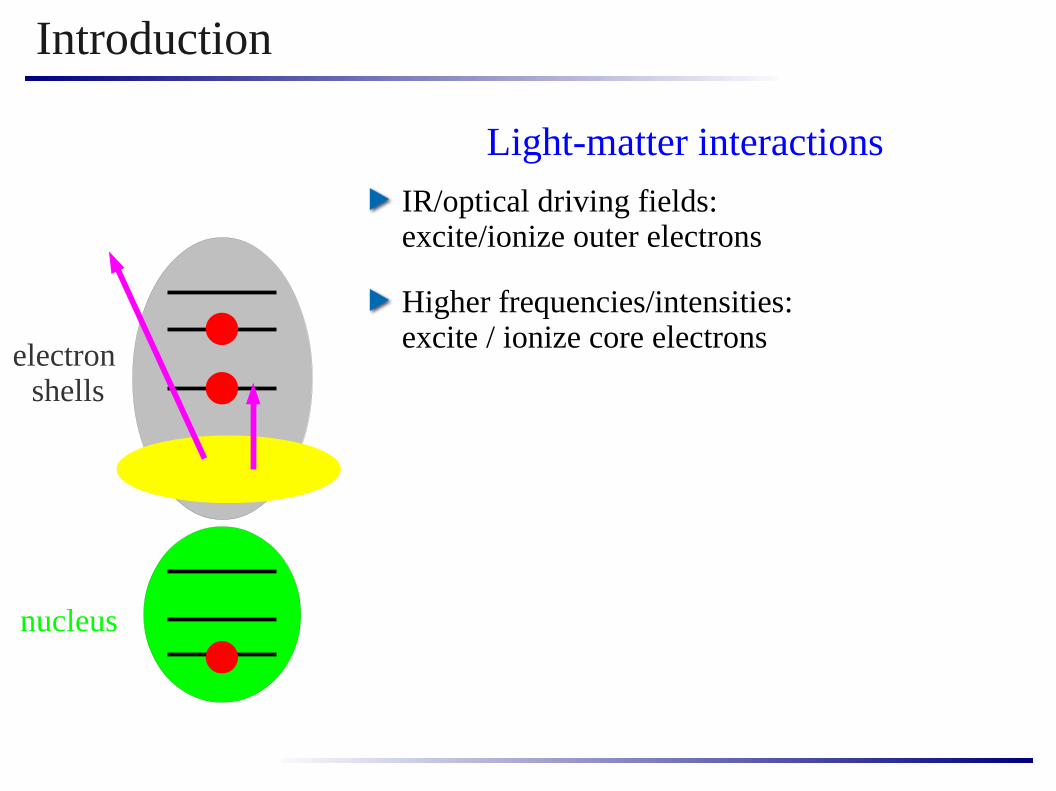
Light-matter interactions

Introduction
nucleus
electron shells
IR/optical driving fields: excite/ionize outer electrons
Light-matter interactions
Introduction
nucleus
electron shells
IR/optical driving fields: excite/ionize outer electrons
Higher frequencies/intensities: excite / ionize core electrons
Light-matter interactions

Introduction
nucleus
electron shells
IR/optical driving fields: excite/ionize outer electrons
Higher frequencies/intensities: excite / ionize core electrons
Even higher frequencies/intensities: excite nucleus
Light-matter interactions

Introduction
nucleus
electron shells
IR/optical driving fields: excite/ionize outer electrons
Higher frequencies/intensities: excite / ionize core electrons
Even higher frequencies/intensities: excite nucleus
Light-matter interactions
What can be done is to a largedegree determined by the
availability of light sources
full quantumcontrol
uncontrolled pump+ passive observation
?

Free electron laser
SLAC linear accelerator
Working principle
Photon energy up to few keV
Full transverse coherence, upgrade to full longitudinal coherence possible
High Brilliance
Short pulses
(image from
Hasylab)
(image from SLAC)

Synchrotron
Flash
XFEL
storage ring
undulator synchrotron radiation
monochromator
Photon energy up to many MeV
Some spatial coherence
Little to no temporal coherence, but monochromator can be used
High Brilliance
Longer pulses
DESY Hamburg(image from DESY)
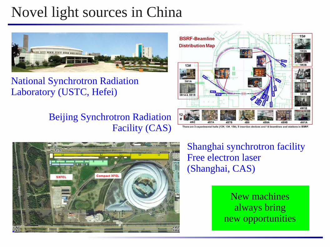
Novel light sources in China
National Synchrotron Radiation Laboratory (USTC, Hefei)
Shanghai synchrotron facilityFree electron laser(Shanghai, CAS)
New machinesalways bring
new opportunities
Beijing Synchrotron Radiation Facility (CAS)
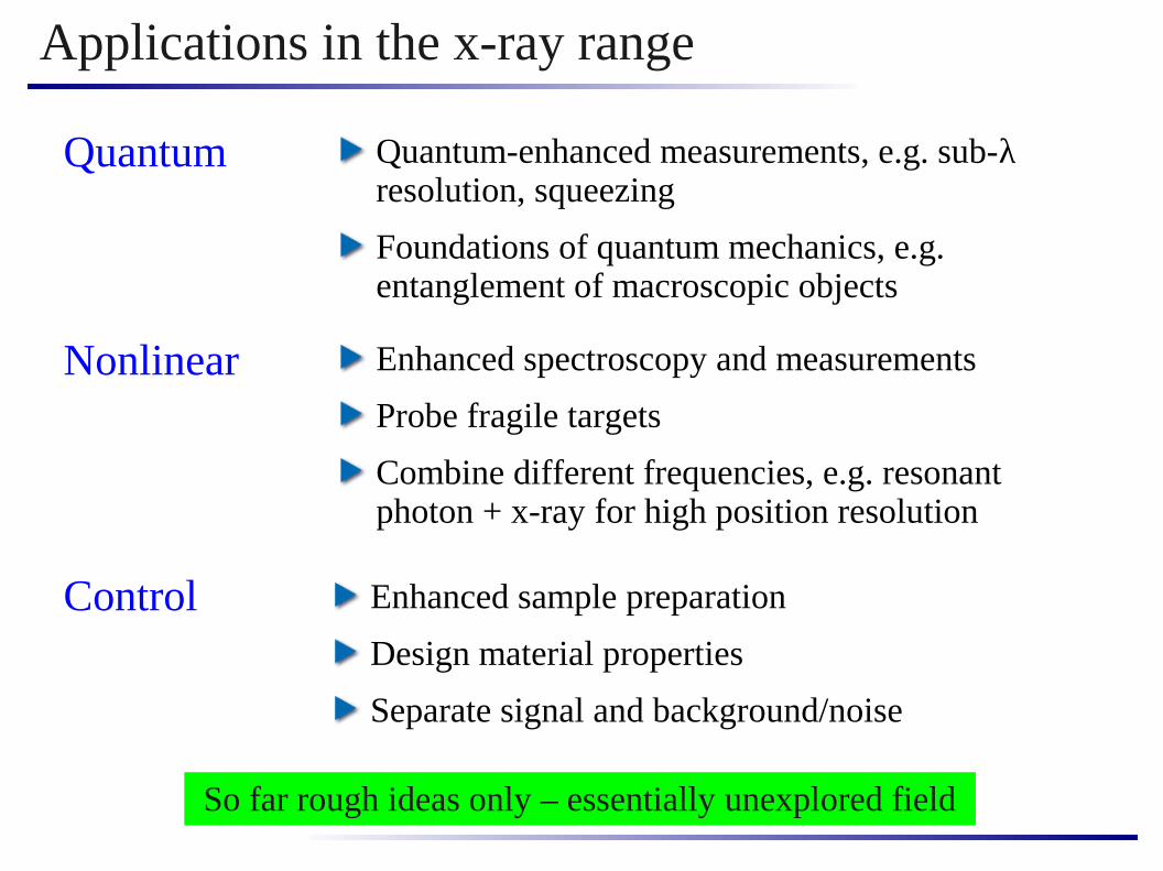
Applications in the x-ray range
Quantum
Nonlinear
Control
Quantum-enhanced measurements, e.g. sub-λ resolution, squeezing
Foundations of quantum mechanics, e.g. entanglement of macroscopic objects
Enhanced spectroscopy and measurements
Probe fragile targets
Combine different frequencies, e.g. resonant photon + x-ray for high position resolution
Enhanced sample preparation
Design material properties
Separate signal and background/noise
So far rough ideas only – essentially unexplored field

X-ray and γ-ray quantum optics @ MPIK
Direct laser driving of nuclei Isomer triggering
Yoctosecond physics X-ray cooperative light scattering
T. Bürvenich, J. Evers, C. H. Keitel, PRL 96, 142501 (2006)
A. Pálffy, J. Evers, C. H. Keitel, PRL 99, 172502 (2007)
A. Ipp, C. H. Keitel, J. Evers,PRL 103, 152301 (2009)
A. Pálffy, C. H. Keitel, J. Evers, PRL 103, 017401 (2009); PRB 83, 155103 (2011)
keV-MeV

Outline
X-ray entanglement generation
X-ray branching ratio control
Introduction
Outlook: Engineering advanced level schemes
?

Cooperative light scattering
quantum particlesas scatterers
scattered light
incident light large dilute cloud
no recoilstationary particles

Elementary processes
incident light
incoherent scattering
no interaction
coherent scattering?
Intermediate excitonic state

Coherent forward scattering
Coherent scattering occurs in forward direction
Similarity to multi-slit / grid diffraction but constructiveinterference only in forward /Bragg direction
grid = CD-R grooves
forward scattering
“Braggscattering”

57Fe iron Mößbauer transition
ground state
excited state
magnetic dipole transition
recoil suppressed due to Mößbauer effect

Temporal beats
+3/2
+1/2
+1/2- 1/2- 3/2
- 1/2bichromatic
scattered light
Scattering on two transitions with same dipole moment, but different transition frequencies
Expect beats in the time-dependent intensity

Multiple scattering
As a model, separate sample into thin layers
Due to forward scattering, first layer is driven only by incident field
Layer n > 1 is in addition driven by “upstream” layers, causing phase shifts
Initial phase synchronization due to incident pulse is dephased
Alternative view: synchrotron excitation does not correspond to radiation eigenmode of the sample
incident light
57Fe sample
incident light+ scattered light
3 41 2 5 6 7
J. P. Hannon and G. T. Trammell, Hyperf. Int. 123/124, 127 (1999)
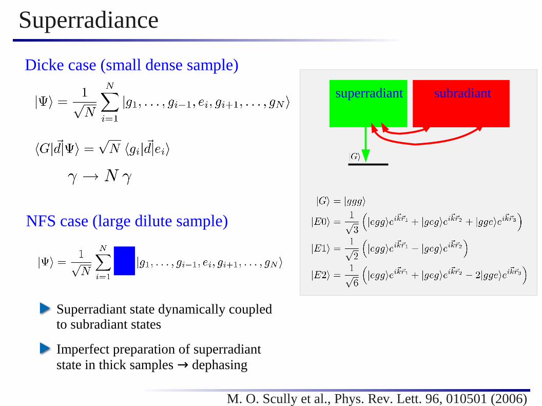
Superradiance
Dicke case (small dense sample)
NFS case (large dilute sample)
superradiant subradiant
Superradiant state dynamically coupledto subradiant states
Imperfect preparation of superradiantstate in thick samples → dephasing
M. O. Scully et al., Phys. Rev. Lett. 96, 010501 (2006)

(Some) characteristic features in NFS spectra
Time
Sig
nal i
nten
sity
superradiance multiple scatteringbeats
exciton

Experimental realization
DESY Hamburg
storage ring
undulator
monochromator
nuclear sample
NFSdetector
Inelasticscattering
synchrotron radiation
source+ drive
detectortarget
shield
Student lab Uni Mailand

Example: Coherent control via magnetic switching
The level structure depends on applied magnetic field: Zeeman splitting
In certain crystals (e.g. FeBO3), the magnetic crystal field is very strong
(~ 30 T), and can be aligned using a weak external field (few Gauss)
This allows to switch the direction of a very strong effective magnetic field in few ns in the lab
HASYLAB F4 beam line Phys. Rev. Lett. 77, 3232 (1996)

Optical response of a single resonance
refraction
absorptionΔ
probe
Ωprobe
medium susceptibility
Δprobe
[γ]
?
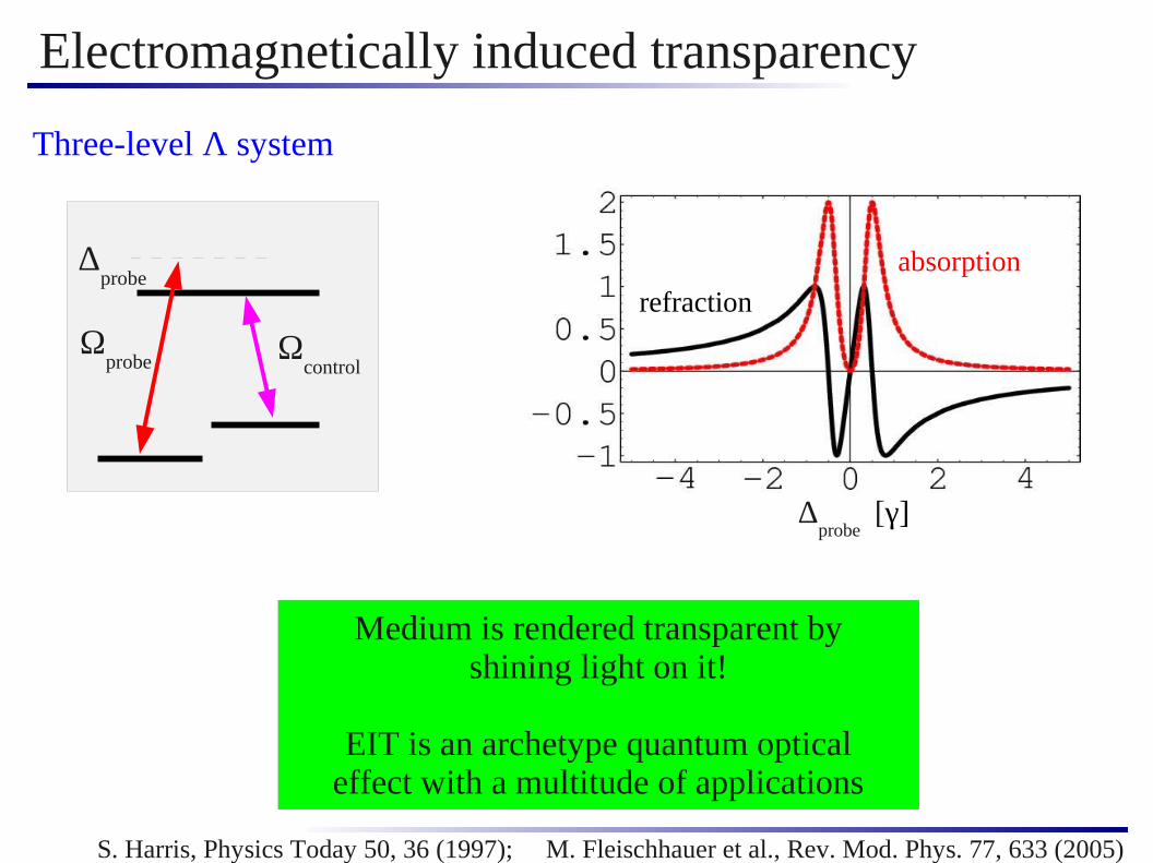
Electromagnetically induced transparency
Three-level Λ system
Δprobe
Ωcontrol
Ωprobe
Medium is rendered transparent byshining light on it!
EIT is an archetype quantum opticaleffect with a multitude of applications
S. Harris, Physics Today 50, 36 (1997); M. Fleischhauer et al., Rev. Mod. Phys. 77, 633 (2005)
absorption
Δprobe
[γ]
refraction

Electromagnetically induced transparency
Interpretation as coherence/interference effect:
If EIT conditions are satisfied:
no excitation ofthe atom due to
destructive interference
coherence
double slitEIT
laser fields drive atom to coherentsuperposition of and
interference: amplitudes for → and → cancel

Coherent control of the exciton
Excite the sample
Rotate quantization axis
Rotate applied magnetic field
Experiment: 30T in 5nspossible in certain crystals
Deexcitation
Destructive interferenceof all pathways possible
Analogy to electromagneticallyinduced transparency
coherence
EIT

Control of coherent NFSNo switching
Control of coherent NFS possible
The coherent decay is (almost) fullysuppressed after switching
Revival of coherent decay afterswitching back
Primary limitation: incoherentdecay with natural lifetime
Applyswitching
Switch back
Decay with natural life
time
Yu. V. Shvyd'ko et al., Phys. Rev. Lett. 77, 3232 (1996)
Experimental verification:

Recent experiment: Collective Lamb Shift
Lamb shift due to virtual photon exchange in ensembles of atoms
Experimentally observed with nuclei using forward scattering
Experimental challenge: Prepare purely superradiant state in thick sample;solution: embed nuclei in low-q cavity
Röhlsberger et al, Science 328, 1248 (2010)
Lamb shift

Outline
X-ray entanglement generation
X-ray branching ratio control
Introduction
Outlook: Engineering advanced level schemes
?

keV single photon entanglement
Motivation
Build up on experimentally demonstrated technique of nuclear switching
Establish coherent control of x-rays on the single photon level
First step towards nonlinear and quantum x-ray science
High photon momentum: x-ray optomechanics,entanglement with more macroscopic objects
More general: New parameter ranges, more complex quantum systems, more robust photons, less thermalbackground noise

Single photon entanglement
beam splitter
Mode A
Mode B
singlephoton
Single photon impinging on 50/50beam splitter gives output
The single photon entangles the twofield modes A and B - the photon itself is not entangled
Applications like Bell violation, teleportationetc. have been proposed
Can be converted to other forms,e.g. “regular” entanglement between atoms
S. J. van Enk, Phys. Rev. A 67, 022303 (2003)
Atom 2
Atom 1
A
B

Advanced magnetic switching schemes
t2 / ns
Rotation angle
Timing
Transition amplitudes
t1
Determines new quantization axis and superposition states
Important due to different transition energies
Determine whether constructive/destructive interference occurs
Example: Suppression at t1 , how does t
2 affect further evolution?
linear
circular
circular
A. Palffy and J. Evers, J. Mod. Opt. 57, 1993 (2010)

Step 1: Synchrotron excitation
x
y
z
Initially, magnetic field is inz direction

Step 2: Canceling coherent decay
x
y
z
Initially, magnetic field is inz direction
At time t1, cancel decay by rotating
into y direction
no switching - switching

Step 3: Releasing circular polarization
x
y
z
Initially, magnetic field is inz direction
At time t1 , cancel decay by rotating
into y direction
At time t2 , enable decay on
but continue to suppress
t2 / ns
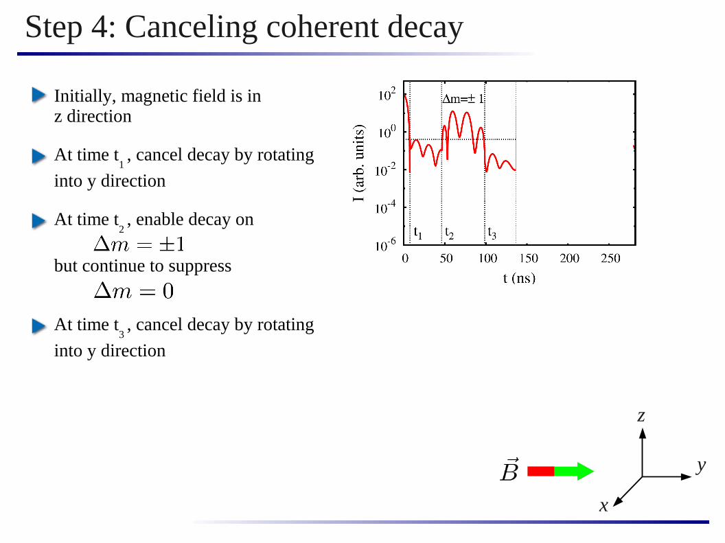
Step 4: Canceling coherent decay
x
y
z
Initially, magnetic field is inz direction
At time t1 , cancel decay by rotating
into y direction
At time t2 , enable decay on
but continue to suppress
At time t3 , cancel decay by rotating
into y direction

Step 5: Releasing linear polarization
x
y
z
Initially, magnetic field is inz direction
At time t1 , cancel decay by rotating
into y direction
At time t2 , enable decay on
but continue to suppress
At time t3 , cancel decay by rotating
into y direction
At time t4 , enable decay on

Temporal mode entanglement
Coherently control exciton decay such that single excitation is distributed into three pulsesNeglecting the background, the two signal pulses are time bin entangledCan extract signal from background and convert it to spatial mode entanglement using x-ray optics
A B
A. Palffy, C. H. Keitel, J. Evers, Phys. Rev. Lett. 103, 017401 (2009)
Design advanced coherent control scheme:

How to extract signal pulse ?
mode A mode B
Priblem: One part of signal has same polarization asbackground pulse
Time gating not useful if following setup should be protected from high-intensity background; lighthouse effect difficult because of prcise timing of nuclear switching
PSM: Piezo electric steering mirror or sub-ns control device based on crystal lattice deformation 1)
Have about 180 ns “steering time” because of magnetic switching
1) A. Grigoriev et al., Appl. Phys. Lett. 89, 021109 (2006)

Proof-of-principle experiment
Do not extract signal, use time gating to remove background
Switching → two entangled overlapping pulses with opposite polarization
Correlation measurement with interferometer, violate Bell-like inequality*)
Need to eliminate “which-way”-information hidden in polarization
“loophole”: explanation of results also possible by non-local classical theory
*) H.-W. Lee and Kim, Phys. Rev. A 63, 012305 (2000)
phaseshiftersplitter
monochromator
sample
detectors
Outline
X-ray entanglement generation
X-ray branching ratio control
Introduction
Outlook: Engineering advanced level schemes
?

Nuclear isomers:
Application: Isomer triggering
See, e.g., P. M. Walker and J. J. Carroll, Nuclear Physics News 17, 11 (2007)
long-lived nuclear statesmay “store” much energy
partial level scheme of 93Mo( t
1/2 = 6.85 h )
42
Motivation:
“nuclear batteries”
gamma-ray laser
fundamental questions in astro- and nuclear physics
How to efficientlypopulate and trigger isomers?

Branching ratio
Single particle branching ratio:
(1-b)· γb· γDetermines ratio of spontaneousemission channels
Property of the particle only
Branching ratio in ensembles
Have cooperative modification ofexcitation and decay
Determined by particle, ensemble and excitation properties, varies with time
Need to define cooperative branching ratio
?

Motivation
Suppress cooperative emission
Then cooperativity leads to enhancedexcitation, but decay proceeds withsingle particle branching ratio
In effect, enhanced pumping to
Aim: Efficiently pump from ground state to isomeric state
Cooperativity leads to enhanced excitation to , but also tofast decay
In effect, little transfer to
Idea:
A. Palffy, C. H. Keitel, and J. Evers, Phys. Rev. B 83, 155103 (2011)

The ideal case
Assume purely superradiantdecay with rate ξ· γ
Assume perfect coherent controlof cooperative decay
Result:
Cooperative branching ratio is larger by factor ξ+1
In addition, cooperative enhancement of excitation
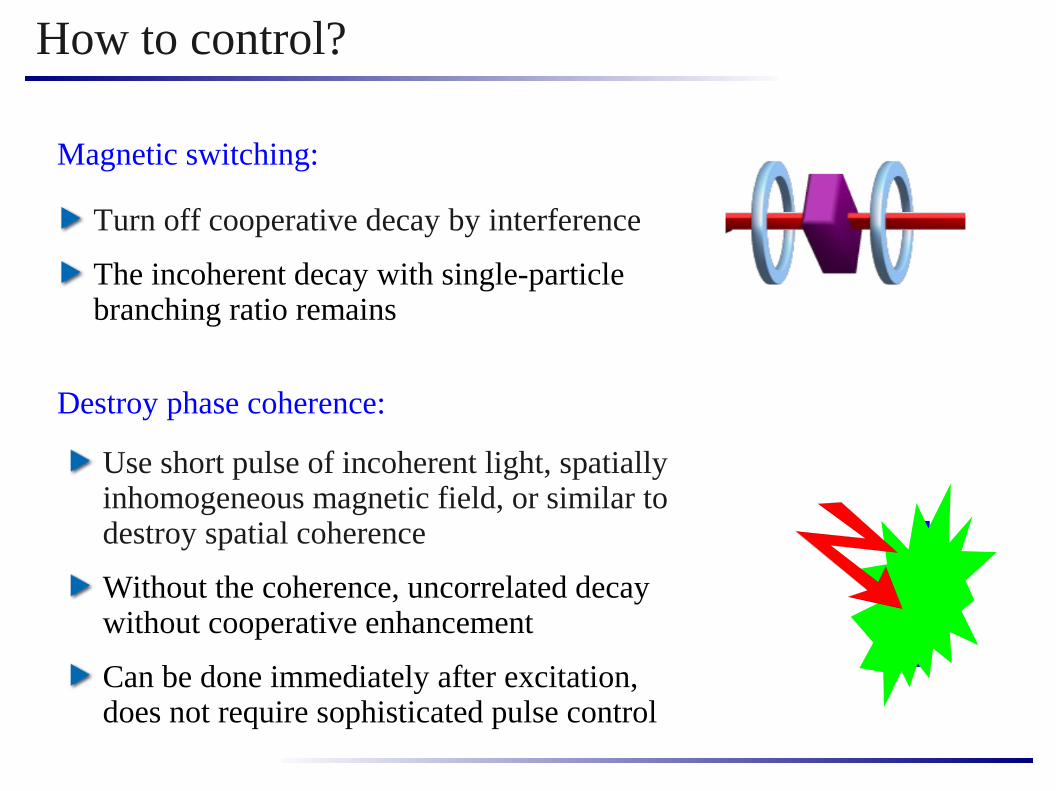
How to control?
Turn off cooperative decay by interference
The incoherent decay with single-particle branching ratio remains
Magnetic switching:
Use short pulse of incoherent light, spatially inhomogeneous magnetic field, or similar to destroy spatial coherence
Without the coherence, uncorrelated decay without cooperative enhancement
Can be done immediately after excitation,does not require sophisticated pulse control
Destroy phase coherence:

The magnetic switching case
Target state population fraction
A. Palffy, C. H. Keitel, and J. Evers, Phys. Rev. B 83, 155103 (2011)
superradiantdecay to initial
state population of sub-radiantstates levels off decay
to initial state➝ limit to enhancement
Switching improves result,but significant decay before
trapping can be achieved➝ better results with
phase destruction

The magnetic switching case
Branching ratio time dependent as expected
Cooperative branching ratio smaller than single-particle ratiodue to superradiance
After switching, single-particle branching ratio is achieved
With destruction of phase coherence, single-particle ratio canimmediately be achieved
Cooperative branching ratio
A. Palffy, C. H. Keitel, and J. Evers, Phys. Rev. B 83, 155103 (2011)

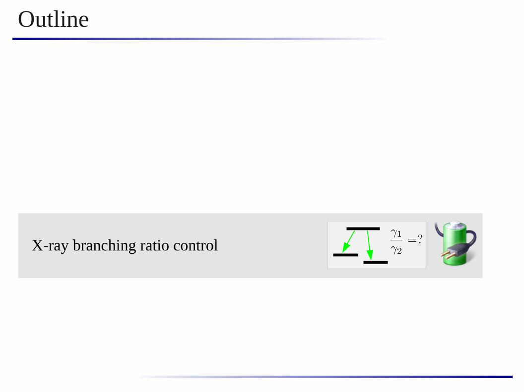
Outline
X-ray entanglement generation
X-ray branching ratio control
Introduction
Outlook: Engineering advanced level schemes
?
substrate
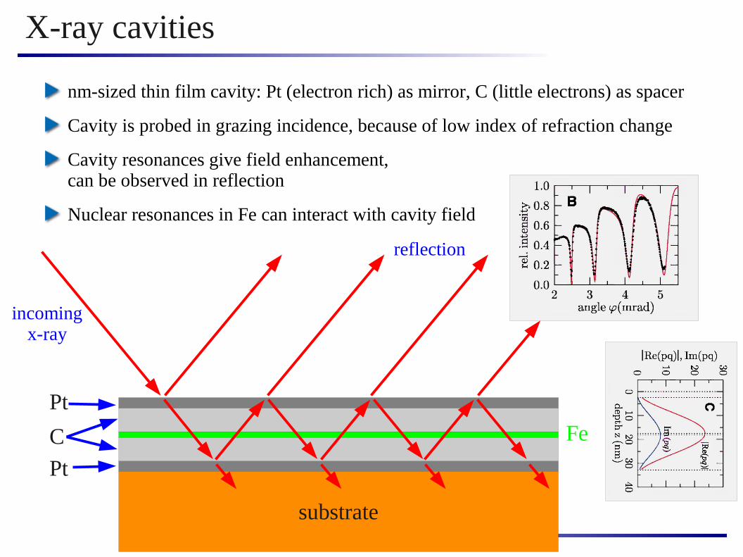
X-ray cavities
Pt
Pt
C Fe
nm-sized thin film cavity: Pt (electron rich) as mirror, C (little electrons) as spacer
Cavity is probed in grazing incidence, because of low index of refraction change
Cavity resonances give field enhancement,can be observed in reflection
Nuclear resonances in Fe can interact with cavity field
incomingx-ray
reflection

Purcell effect and cooperativity
Look at cavity with 2 active layers- (A) in cavity field maximum- (B) in cavity field minimum
(A) couples strongly to the cavity, rapidly emits excitation into cavity field (Purcell effect + cooperative light emission)
(b) has suppressed coupling to cavity because of intensity minimum
(A)(B)
Lifetime of nuclearexcitation in (B)much longer thanthat of one in (A)
Material is the same!
Image: Röhlsberger et al, Nature 482, 199 (2012)

Engineering a 3-level Λ level scheme
State |1> : no excitations in (A), (B)but photon in cavity
State |3>: excitation in (A), no photon in cavity
State |2>: excitation in (B), no photon in cavity
(A)(B)
The level scheme
Why is this a Λ level scheme?
|3> decays fast due to Purcell + cooperativity
Compared to that, |2> and |1> metastable
Control is generated by scattering between the layers
Probe field by absorption of cavity photonby nucleus in (A)
Image: Röhlsberger et al, Nature 482, 199 (2012)

Experiment: Nuclear EIT
Experiment + Theory including detection
Theory
EIT setup
reference setup
EIT as an archetype quantum optical coherence effectobserved with x-rays interacting with nuclei
EIT with a single light field due to clever cavity engineering
Image: Röhlsberger et al, Nature 482, 199 (2012)

Our current work: engineer advanced schemes
absorption
Δprobe
[γ]
refraction
transparency window
dispersion slope
Broad transparency window to propagate of broadband input pulses
Steep dispersion slope for strong effect on propagated pulse (e.g. delay)
(time delay)∙(transparency bandwidth)is constant → need to tune for best trade-off
probe - coupling
More general level schemes offer wide range of applications
Example: Strongly enhanced non-linear response
Δ
K. P. Heeg, R. Röhlsberger, J. Evers, work in progress

The team
Martin Gärttner PhD student
Qurrat-ul-Ain Gulfam PhD student
Kilian Heeg PhD student
Mihai Macovei PostDoc
Andreas Reichegger Master student
Sandra Schmid PostDoc
Lida Zhang PhD student
Funding: MPG, DFG, DAAD, IMPRS-QD, CQD
Acknowledgements:
Ralf Röhlsberger (DESY Hamburg)Adriana Palffy (former group member @ MPIK)

Summary
X-ray entanglement generation
X-ray branching ratio control
Introduction
Outlook: Engineering advanced level schemes
?

Thank you!
PhD / PostDoc applications
welcome in Heidelberg!


NFS

Theoretical description
Wave equation
Slowly varying envelope approximation
Nuclei as source term (2nd order)
Final wave equation
excitationde-excitationsum overtransitions Y. V. Shvydko, Hyperf. Int. 123/124, 275 (1999)
Iterative solution,incident pulse

A few numbers - classification of the system
Incident light bandwidth ~meV, Fe transition width ~neV→ on average typically less than 1 excited nucleus per shot, “single photon”
Solid state densities ( n ~1023 / cm3 ) but short wavelength ( λ ~10-10 m )→ nλ3 ~ 0.1 → “dilute” medium
High resonant scattering amplitude, Mößbauer effect→ large optical depth, multiple scattering
Sample of macroscopic size compared to wave length (R / λ » 1)
Focus on coherent forward scattering→ Treatment of cooperative effects much simplified (e.g., no radiation trapping)
Single resonant photon
Dilute cloud of atoms
coherent scattering

violated for some phase shifts
Possible proof-of-principle experiment
H.-W. Lee and Kim, Phys. Rev. A 63, 012305 (2000)
Without phase shifts: All N photons go to C (GN)
With phase shift by Alice: photons go to D (G
A)
With phase shift by Bob: photons go to D (G
B)
With both phase shifts: go to D (G
AB)
Locality assumption: photons which arrive at C both if (Alice shifts but not Bob) and if (Bob shifts but not Alice)will still arrive at C if (Alice and Bob shift) (GN−GA)∩(GN−GB)⊆(GN−GAB)
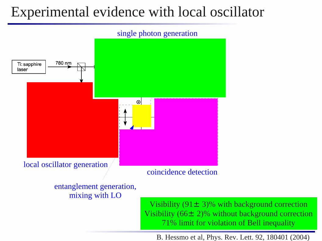
Experimental evidence with local oscillator
B. Hessmo et al, Phys. Rev. Lett. 92, 180401 (2004)
single photon generation
local oscillator generation
entanglement generation,mixing with LO
coincidence detection
Visibility (91± 3)% with background correctionVisibility (66± 2)% without background correction
71% limit for violation of Bell inequality
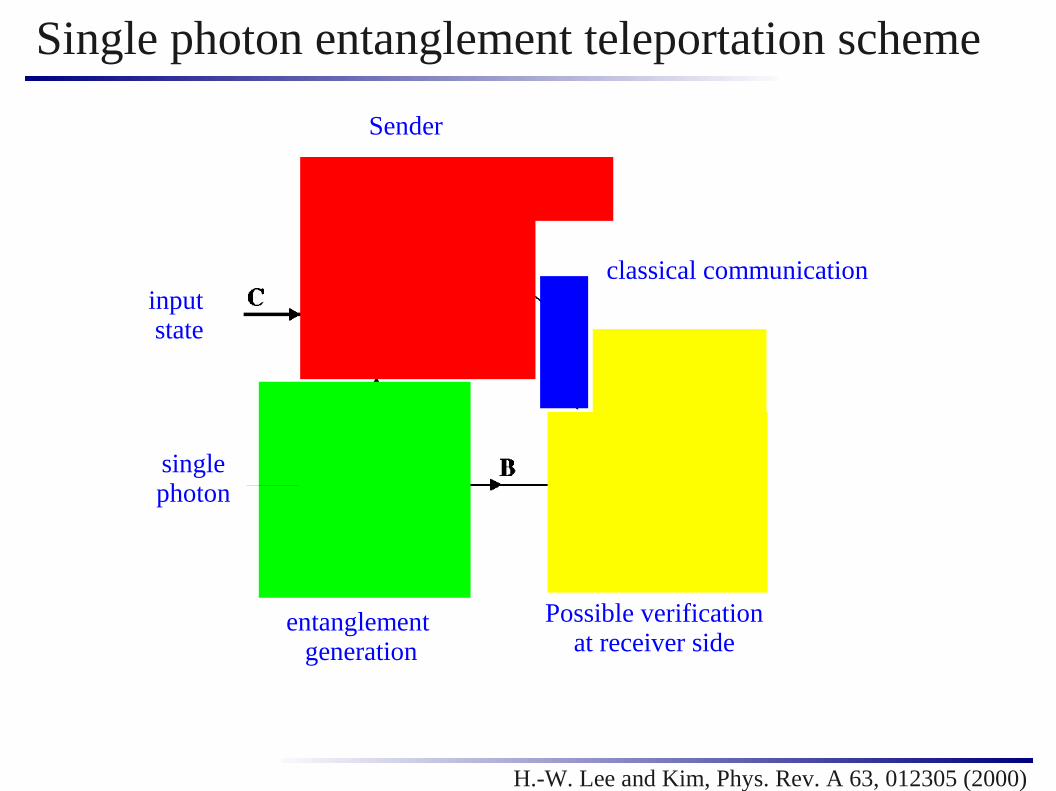
Single photon entanglement teleportation scheme
H.-W. Lee and Kim, Phys. Rev. A 63, 012305 (2000)
Sender
entanglement generation
Possible verificationat receiver side
classical communicationinput state
singlephoton

Teleportation algebra
H.-W. Lee and Kim, Phys. Rev. A 63, 012305 (2000)
entanglement input
teleported state
measurement Alice

Efficiency estimate
Assumed incoming flux after monochromator: 109 photons / s
Assumed rate of excited nuclei: 5 ⨯ 105 / s
Of stored excitation, 70% background, 30% signal
Loss at polarizer: Only about 10% of photons are kept
Single photon entanglement rate: 15 ⨯ 103 / s
A. Palffy, C. H. Keitel, J. Evers, Phys. Rev. Lett. 103, 017401 (2009)
background70%30%
signal
suppressionsuppressionSignal and background
separated!
Incident photon fluxcan be increased until
multiple excitations occur