qsl9-g3...ucdi274k specifications & options standards newage stamford industrial generators meet...
TRANSCRIPT

Our energy working for you.™
www.cumminsgdrive.com
©2011Cummins G-Drive EnginesSpecifications Subject to Change Without NoticeCummins is a registered trademark of Cummins Inc. (03/11)
QSL9-G3 Emissions Compliance: EU Stage IIIA at 50 Hz EPA NSPS Stationary Emergency Tier 3
Description Cummins QSL engines are built to deliver heavy-duty performance. Full-authority electronic engine controls combine with the high-pressure fuel system, 24-valve design and centred injectors for one of the highest power-to-weight ratios in its class. At the same time, the QSL delivers better fuel economy, has better cold starting capability and is up to 50% quieter in operation than its predecessors.
Features Common Rail Fuel System and Controls - Bosch high pressure common rail (HPCR) - Optimize engine performance to provide seamless integration and advanced diagnostics and programming options. Holset HX40 Turbo charging – Waste-gated design optimizes transient response. Integrated Block Design - Integrated fluid circuits replace hoses and eliminate potential leaks. 24-Valve Cylinder Head – Four valves per cylinder for increased power with faster response & fuel economy. Coolpac Integrated Design - Products are supplied complete with cooling package and air cleaner kit for a complete power package. Each component has been specifically developed and rigorously tested for G-Drive products, ensuring high performance, durability and reliability. Service and Support - G-Drive products are backed by an uncompromising level of technical support and after sales service, delivered through a world class service network.
This engine has been built to comply with CE certification.
This engine has been designed in facilities certified to ISO9001 and manufactured in facilities certified to ISO9001 or ISO9002.
1500 rpm (50 Hz Ratings)
Gross Engine Output Net Engine Output Typical Generator Set Output
Standby Prime Base Standby Prime Base Standby (ESP) Prime (PRP) Base (COP)
kWm/BHP kWm/BHP kWe kVA kWe kVA kWe kVA
257/345 227/305 193/259 244/327 217/291 183/245 220 275 200 250 170 213
1800 rpm (60 Hz Ratings)
Gross Engine Output Net Engine Output Typical Generator Set Output
Standby Prime Base Standby Prime Base Standby (ESP) Prime (PRP) Base (COP)
kWm/BHP kWm/BHP kWe kVA kWe kVA kWe kVA
297/399 262/352 178/238 280/375 248/332 164/219 250 313 227 284 152 190

Our energy working for you.™
www.cumminsgdrive.com
©2007Cummins G-Drive EnginesSpecifications Subject to Change Without NoticeCummins is a registered trademark of Cummins Inc. (01/08) (GDSS122)
General Engine Data Ratings Definitions
Type 4 cycle, in-line, Turbo Charged, Air-cooled
Emergency Standby Power (ESP):Applicable for supplying power to varying electrical load for the duration of power interruption of a reliable utility source. Emergency Standby Power (ESP) is in accordance with ISO 8528. Fuel Stop power in accordance with ISO 3046, AS 2789, DIN 6271 and BS 5514. Limited-Time Running Power (LTP): Applicable for supplying power to a constant electrical load for limited hours. Limited-Time Running Power (LTP) is in accordance with ISO 8528. Prime Power (PRP): Applicable for supplying power to varying electrical load for unlimited hours. Prime Power (PRP) is in accordance with ISO 8528. Ten percent overload capability is available in accordance with ISO 3046, AS 2789, DIN 6271 and BS 5514. Base Load (Continuous) Power (COP): Applicable for supplying power continuously to a constant electrical load for unlimited hours. Continuous Power (COP) in accordance with ISO 8528, ISO 3046, AS 2789, DIN6271 and BS 5514.
Bore mm 114 mm (4.5in.)
Stroke mm 145 mm (5.7in.)
Displacement Litre 8.8 litre (543 in.3)
Cylinder Block Cast iron, 6 cylinder
Battery Charging Alternator 70 amps
Starting Voltage 24 volt, negative ground Fuel System Direct injection Fuel Filter Spin-on fuel filters with water separator
Lube Oil Filter Type(s) Spin-on full flow filter Lube Oil Capacity (l) 26.5 Flywheel Dimensions SAE1/14
Coolpac Performance Data Cooling System Design Air-Air Charge Cooled
Coolant Ratio 50% ethylene glycol; 50% water
Coolant Capacity (l) 15.0
Limiting Ambient Temp.** (°C) 50 (50Hz); 55 (60Hz)
Fan Power (kWm) 10 (50Hz); 11 (60Hz)
Cooling System Air Flow (m3/s)** 7.9 (50Hz); 8 (60Hz) Air Cleaner Type Light duty dry replaceable element with
restriction indicator ** @ 13 mm H20
Weight & Dimensions
Length Width Height Weight (dry) mm mm mm kg 1624 1064 1463 861
Fuel Consumption 1500 (50 Hz) Fuel Consumption 1800 (60 Hz)
% kWm BHP L/ph US gal/ph % kWm BHP L/ph US gal/ph
Standby Power Standby Power
100 257 345 66 17.3 100 297 399 77 20.4
Prime Power Prime Power
100 227 305 59 15.6 100 262 352 70 18.5
75 170 228 49 13.0 75 197 264 58 15.2
50 114 152 34 8.9 50 131 176 41 10.8
25 57 76 18 4.7 25 66 88 21 5.6
Continuous Power Continuous Power
100 193 259 53 14.1 100 178 238 53 14.1 Cummins G-Drive Engines
Asia Pacific 10 Toh Guan Road #07-01 TT International Tradepark Singapore 608838 Phone 65 6417 2388 Fax 65 6417 2399
Europe, CIS, Middle East and Africa Manston Park Columbus Ave Manston Ramsgate Kent CT12 5BF. UK Phone 44 1843 255000 Fax 44 1843 255902
Latin America Rua Jati, 310, Cumbica Guarulhos, SP 07180-900 Brazil Phone 55 11 2186 4552 Fax 55 11 2186 4729
Mexico Cummins S. de R.L. de C.V. Eje 122 No. 200 Zona Industrial San Luis Potosí, S.L.P. 78090 Mexico Phone 52 444 870 6700 Fax 52 444 870 6811
North America 1400 73rd Avenue N.E. Minneapolis, MN 55432 USA Phone 1 763 574 5000 USA Toll-free 1 877 769 7669 Fax 1 763 574 5298

UCDI274K - Technical Data Sheet
UCDI274KSPECIFICATIONS & OPTIONS
STANDARDSNewage Stamford industrial generators meet therequirements of BS EN 60034 and the relevant sectionof other international standards such as BS5000, VDE0530, NEMA MG1-32, IEC34, CSA C22.2-100, AS1359.Other standards and certifications can be considered onrequest.
VOLTAGE REGULATORS
SX460 AVR - STANDARDWith this self excited control system the main statorsupplies power via the Automatic Voltage Regulator(AVR) to the exciter stator. The high efficiencysemiconductors of the AVR ensure positive build-upfrom initial low levels of residual voltage.The exciter rotor output is fed to the main rotor througha three phase full wave bridge rectifier. This rectifier isprotected by a surge suppressor against surgescaused, for example, by short circuit.
SX440 AVR With this self-excited system the main stator providespower via the AVR to the exciter stator. The highefficiency semi-conductors of the AVR ensure positivebuild-up from initial low levels of residual voltage.The exciter rotor output is fed to the main rotor througha three-phase full-wave bridge rectifier. The rectifier isprotected by a surge suppressor against surgescaused, for example, by short circuit or out-of-phaseparalleling.The SX440 will support a range of electronicaccessories, including a 'droop' Current Transformer(CT) to permit parallel operation with other acgenerators.If 3-phase sensing is required with the self-excitedsystem, the SX421 AVR must be used.
SX421AVRThis AVR also operates in a self-excited system. Itcombines all the features of the SX440 with,additionally, three-phase rms sensing for improvedregulation and performance. Over voltage protection isprovided via a separate circuit breaker. An engine reliefload acceptance feature is built in as standard.
MX341 AVRThis sophisticated AVR is incorporated into theStamford Permanent Magnet Generator (PMG) controlsystem.The PMG provides power via the AVR to the mainexciter, giving a source of constant excitation powerindependent of generator output. The main exciteroutput is then fed to the main rotor, through a full wavebridge, protected by a surge suppressor. The AVR hasin-built protection against sustained over-excitation,caused by internal or external faults. This de-excitesthe machine after a minimum of 5 seconds.An engine relief load acceptance feature can enable fullload to be applied to the generator in a single step.If three-phase sensing is required with the PMG systemthe MX321 AVR must be used.We recommend three-phase sensing for applicationswith greatly unbalanced or highly non-linear loads.
MX321 AVRThe most sophisticated of all our AVRs combines all thefeatures of the MX341 with, additionally, three-phaserms sensing, for improved regulation and performance.Over voltage protection is built-in and short circuitcurrent level adjustments is an optional facility.
WINDINGS & ELECTRICAL PERFORMANCEAll generator stators are wound to 2/3 pitch. Thiseliminates triplen (3rd, 9th, 15th …) harmonics on thevoltage waveform and is found to be the optimumdesign for trouble-free supply of non-linear loads. The2/3 pitch design avoids excessive neutral currentssometimes seen with higher winding pitches, when inparallel with the mains. A fully connected damperwinding reduces oscillations during paralleling. Thiswinding, with the 2/3 pitch and carefully selected poleand tooth designs, ensures very low waveformdistortion.
TERMINALS & TERMINAL BOXStandard generators are 3-phase reconnectable with 12ends brought out to the terminals, which are mountedon a cover at the non-drive end of the generator. Asheet steel terminal box contains the AVR and providesample space for the customers' wiring and glandarrangements. It has removable panels for easyaccess.
SHAFT & KEYSAll generator rotors are dynamically balanced to betterthan BS6861:Part 1 Grade 2.5 for minimum vibration inoperation.
INSULATION/IMPREGNATIONThe insulation system is class 'H'.All wound components are impregnated with materialsand processes designed specifically to provide the highbuild required for static windings and the highmechanical strength required for rotating components.
QUALITY ASSURANCE
Generators are manufactured using productionprocedures having a quality assurance level to BS ENISO 9001.
The stated voltage regulation may not be maintained inthe presence of certain radio transmitted signals. Anychange in performance will fall within the limits ofCriteria 'B' of EN 61000-6-2:2001. At no time will thesteady-state voltage regulation exceed 2%.
NB Continuous development of our products entitles usto change specification details without notice, thereforethey must not be regarded as binding.
Front cover drawing typical of product range.
2

CONTROL SYSTEM SEPARATELY EXCITED BY P.M.G.
A.V.R. MX321 MX341
VOLTAGE REGULATION ± 0.5 % ± 1.0 % With 4% ENGINE GOVERNING
SUSTAINED SHORT CIRCUIT
CONTROL SYSTEM SELF EXCITED
A.V.R. SX460 SX440 SX421
VOLTAGE REGULATION ± 1.5 % ± 1.0 % ± 0.5 % With 4% ENGINE GOVERNING
SUSTAINED SHORT CIRCUIT SERIES 4 CONTROL DOES NOT SUSTAIN A SHORT CIRCUIT CURRENT
INSULATION SYSTEM CLASS H
PROTECTION
RATED POWER FACTOR
STATOR WINDING
WINDING PITCH
WINDING LEADS
STATOR WDG. RESISTANCE
ROTOR WDG. RESISTANCE
EXCITER STATOR RESISTANCE
EXCITER ROTOR RESISTANCE
R.F.I. SUPPRESSION BS EN 61000-6-2 & BS EN 61000-6-4,VDE 0875G, VDE 0875N. refer to factory for others
WAVEFORM DISTORTION NO LOAD < 1.5% NON-DISTORTING BALANCED LINEAR LOAD < 5.0%
MAXIMUM OVERSPEED
BEARING NON-DRIVE END
WEIGHT COMP. GENERATOR
WEIGHT WOUND STATOR
WEIGHT WOUND ROTOR
WR² INERTIA
SHIPPING WEIGHTS in a crate
PACKING CRATE SIZE
TELEPHONE INTERFERENCE
COOLING AIR
VOLTAGE SERIES STAR (Y) 380/220 400/231 415/240 440/254 416/240 440/254 460/266 480/277
VOLTAGE PARALLEL STAR (Y) 190/110 200/115 208/120 220/127 208/120 220/127 230/133 240/138
VOLTAGE SERIES DELTA 220/110 230/115 240/120 254/127 240/120 254/127 266/133 277/138kVA BASE RATING FOR REACTANCE VALUES
250 250 250 n/a 291 299 312.5 312.5
Xd DIR. AXIS SYNCHRONOUS 2.825 2.550 2.369 - 3.161 2.903 2.776 2.550
X'd DIR. AXIS TRANSIENT 0.132 0.119 0.111 - 0.148 0.136 0.130 0.119
X''d DIR. AXIS SUBTRANSIENT 0.086 0.078 0.072 - 0.097 0.089 0.085 0.078
Xq QUAD. AXIS REACTANCE 1.263 1.140 1.059 - 1.413 1.298 1.241 1.140
X''q QUAD. AXIS SUBTRANSIENT 0.152 0.137 0.127 - 0.170 0.156 0.149 0.137
XL LEAKAGE REACTANCE 0.066 0.060 0.056 - 0.074 0.068 0.065 0.060
X2 NEGATIVE SEQUENCE 0.120 0.108 0.100 - 0.134 0.123 0.118 0.108
X0 ZERO SEQUENCE 0.022 0.020 0.019 - 0.025 0.023 0.022 0.020
REACTANCES ARE SATURATED VALUES ARE PER UNIT AT RATING AND VOLTAGE INDICATEDT'd TRANSIENT TIME CONST.T''d SUB-TRANSTIME CONST.T'do O.C. FIELD TIME CONST.Ta ARMATURE TIME CONST.
SHORT CIRCUIT RATIO
2250 Rev/Min
727 kg
TWO THIRDS
12
20 Ohms at 22°C
0.091 Ohms PER PHASE AT 22°C
UCDI274KWINDING 311
IP23
0.8
0.58 m³/sec 1230 cfm 0.69 m³/sec 1463 cfm
50 Hz
THF<2%
60 Hz
TIF<50
1/Xd
0.049 s0.02 s1.27 s0.018 s
123 x 67 x 103 (cm)
REFER TO SHORT CIRCUIT DECREMENT CURVES (page 7)
2.08 Ohms at 22°C
0.0126 Ohms PER PHASE AT 22°C SERIES STAR CONNECTED
2.3934 kgm2
740 kg
304 kg
272.6 kg
BALL. 6310-2RS (ISO)
DOUBLE LAYER CONCENTRIC
3

Winding 311UCDI274K
THREE PHASE EFFICIENCY CURVES
50Hz
4
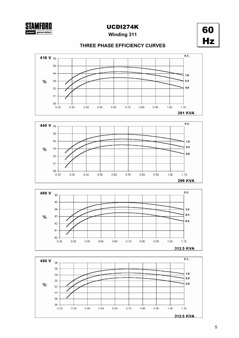
Winding 311UCDI274K
THREE PHASE EFFICIENCY CURVES
60Hz
5

UCDI274KWinding 311
Locked Rotor Motor Starting Curve
MX SX
50Hz
60Hz
MX SX
0
5
10
15
20
25
30
0 100 200 300 400 500 600 700 800 900LOCKED ROTOR kVA
PE
R C
EN
T TR
AN
SIE
NT
VO
LTA
GE
DIP
.
380V 400V 415V 440V
0
5
10
15
20
25
30
0 100 200 300 400 500 600 700 800LOCKED ROTOR kVA
PE
R C
EN
T TR
AN
SIE
NT
VO
LTA
GE
DIP
.
380V 400V 415V 440V
0
5
10
15
20
25
30
0 100 200 300 400 500 600 700 800 900 1000LOCKED ROTOR kVA
PE
R C
EN
T TR
AN
SIE
NT
VO
LTA
GE
DIP
.
416V 440V 460V 480V
0
5
10
15
20
25
30
0 100 200 300 400 500 600 700 800 900LOCKED ROTOR kVA
PE
R C
EN
T TR
AN
SIE
NT
VO
LTA
GE
DIP
.
416V 440V 460V 480V
6

3-phase 2-phase L-L 1-phase L-NVoltage Factor Voltage Factor x 1.00 x 0.87 x 1.30
380v X 1.00 416v X 1.00 x 1.00 x 1.80 x 3.20400v X 1.05 440v X 1.07 x 1.00 x 1.50 x 2.50415v X 1.10 460v X 1.12 10 sec. 5 sec. 2 sec.440v X 1.16 480v X 1.16
UCDI274K
50Hz 60Hz
The sustained current value is constant irrespectiveof voltage level
Three-phase Short Circuit Decrement Curve. No-load Excitation at Rated SpeedBased on star (wye) connection.
Max. sustained durationAll other times are unchanged
Instantaneous
SustainedMinimum
Sustained Short Circuit = 850 Amps
Sustained Short Circuit = 1,000 AmpsNote 1The following multiplication factors should beused to adjust the values from curve betweentime 0.001 seconds and the minimum currentpoint in respect of nominal operating voltage :
Note 2The following multiplication factor should be used to convert thevalues calculated in accordance with NOTE 1 to those applicableto the various types of short circuit :
Note 3Curves are drawn for Star (Wye) connected machines. For otherconnection the following multipliers should be applied to currentvalues as shown : Parallel Star = Curve current value X 2Series Delta = Curve current value X 1.732
50Hz
60Hz
100
1000
10000
0.001 0.01 0.1 1 10TIME (secs)
CU
RR
EN
T (
Am
ps)
SYMMETRICAL
ASYMMETRICAL
100
1000
10000
0.001 0.01 0.1 1 10TIME (secs)
CU
RR
EN
T (
Am
ps)
SYMMETRICAL
ASYMMETRICAL
7

Class - Temp Rise
Series Star (V) 380 400 415 440 380 400 415 440 380 400 415 440 380 400 415 440
Parallel Star (V) 190 200 208 220 190 200 208 220 190 200 208 220 190 200 208 220
Series Delta (V) 220 230 240 254 220 230 240 254 220 230 240 254 220 230 240 254
kVA 229.0 229.0 229.0 n/a 250.0 250.0 250.0 n/a 265.0 265.0 265.0 n/a 275.0 275.0 275.0 n/a
kW 183.2 183.2 183.2 n/a 200.0 200.0 200.0 n/a 212.0 212.0 212.0 n/a 220.0 220.0 220.0 n/a
Efficiency (%) 92.8 93.0 93.1 n/a 92.5 92.7 92.8 n/a 92.2 92.4 92.6 n/a 92.0 92.2 92.4 n/a
kW Input 197.4 197.0 196.8 n/a 216.2 215.7 215.5 n/a 229.9 229.4 228.9 n/a 239.1 238.6 238.1 n/a
Series Star (V) 416 440 460 480 416 440 460 480 416 440 460 480 416 440 460 480
Parallel Star (V) 208 220 230 240 208 220 230 240 208 220 230 240 208 220 230 240
Series Delta (V) 240 254 266 277 240 254 266 277 240 254 266 277 240 254 266 277
kVA 267.0 275.0 286.5 286.5 291.0 299.0 312.5 312.5 304.0 312.5 331.3 331.3 312.0 320.0 343.8 343.8
kW 213.6 220.0 229.2 229.2 232.8 239.2 250.0 250.0 243.2 250.0 265.0 265.0 249.6 256.0 275.0 275.0
Efficiency (%) 92.9 93.0 93.1 93.2 92.6 92.7 92.8 92.9 92.4 92.6 92.5 92.7 92.2 92.4 92.3 92.5
kW Input 229.9 236.6 246.2 245.9 251.4 258.0 269.4 269.1 263.2 270.0 286.5 285.9 270.7 277.1 298.0 297.3
TD_UCDI274K.GB_12.03_03_GB
Cont. F - 105/40°C Cont. H - 125/40°C Standby - 150/40°C Standby - 163/27°C
DIMENSIONS
UCDI274KWinding 311 / 0.8 Power Factor
RATINGS
Barnack Road • Stamford • Lincolnshire • PE9 2NBTel: 00 44 (0)1780 484000 • Fax: 00 44 (0)1780 484100Website: www.newage-avkseg.com
© 2004 Newage International Limited.Reprinted with permission of N.I. only.Printed in England.
50Hz
60Hz