pvbook pressure vessel design book
DESCRIPTION
PV book is pressure vessel design book.Which explores design perspectives of pressure vessel design.TRANSCRIPT
Pressure VesselDesign,Guides & Procedures
Authors/Compilers Committee
G. GhanbariM.A. LiaghatA. SadeghianA. MahootchiI. SokoutiR. HeidaryM.H. MohammadiA. AnsarifardM. Seraj
www.pv-book.comEmail:[email protected]
Vessel Pressure
Design,Guides & Procedures
Pressure VesselDesign, G
uides & Procedures
The main purpose of this book is to present guides, procedures, and design principles for pressure vessels to enhance the understanding of designing process in this field.The economical pressure vessel design can only be accomplished through the application of various theoretical principles combined with industrial and practical knowledge. Therefore, both theory and practice are emphasized in this book and different aspects of pressure vessel requirements are included. The book contains 10 chapters to cover all parts of designing and testing. To its advantages, each designing chapter includes some flowcharts as guides to illustrate a stepwise sequence of the design. Moreover, the designing chapters are supported by an example to clarify each step for designers. Consequently, the designing steps are instructed and outlined using PV-Elite soft-ware which can pave the way for the designers to use the software to ease their calculations.
i
Pressure Vessel Design
Guides & Procedures

ii

iii
Preface In this modern age of industrial competition, a successful pressure vessel designer needs more than a
knowledge and understanding of the fundamental sciences and the related mechanical engineering subjects.
He must also have the ability to apply this knowledge to practical situations for the purpose of accurate and
beneficial design of a pressure vessel. To achieve this goal, the present book “Pressure Vessel Design, Guides
& Procedures” is co-authored by a group of well experienced mechanical engineers who are working in the
mechanical department of a company active in petrochemical industry named Hampa Energy Engineering &
Design Company, HEDCO (www.hedcoint.com).
The main purpose of this book is to present guides, procedures, and design principles for pressure vessels
to enhance the understanding of designing process in this field. The economical pressure vessel design can
only be accomplished through the application of various theoretical principles combined with industrial and
practical knowledge. Therefore, both theory and practice are emphasized in this book and different aspects
of pressure vessel requirements are included. The book contains 10 chapters to cover all parts of designing
and testing. To its advantages, each designing chapter includes some flowcharts as guides to illustrate a
stepwise sequence of the design. Moreover, the designing chapters are supported by an example to clarify
each step for designers. Consequently, the designing steps are instructed and outlined using PV-Elite soft-
ware which can pave the way for the designers to use the software to ease their calculations.
Furthermore, the book would not only be suitable for pressure vessel designers, but also educators and
students can use it in their courses. It is assumed that the readers have a background in mechanical and
material engineering. The coherent SI system is mostly used as the unit for formulas and calculations of the
book. Every effort has been made to assure the preciseness and credibility of the data contained herein.
However, it is worthy to note that the authors assume no responsibility against the designs based on the
presented formulas.
It is hoped that this book will meet all the requirements for pressure vessel technologist and designers and
also, can bridge the gaps in pressure vessel designing industry in this technology driven world. The authors
are indebted to many industrial and informative books and references, and individuals who have supplied
information and comments on the materials presented in this book. It has been attempted to preserve all
the rights for the referenced articles and books all through the compilation stages.
Authors Committee
July, 2011

iv
About the Authors This book “Pressure Vessel Design, Guides & Procedures” is compiled and authored by a group of mechani-
cal engineers active in pressure vessel design projects and trainings (www.pv-book.com). The authors and
compilers committee members are listed below:
Mr. Ghader Ghanbari, MSc. In Solid Mechanics
Mr. Mohammad Ali Liaghat, MSc. In Mechanical Engineering Manufacturing & Production
Mr. Ali Sadeghian, BSc. In Fluid Mechanics
Mr. Alireza Mahootchi, BSc. In Fluid Mechanics
Mr. Iman Sokouti, MSc. In Solid Mechanics
Mr. Roohollah Heidary, MSc. In Solid Mechanics
Mr. MohammadHassan Mohammadi, BSc. In Fluid Mechanics
Mr. Amir Ansarifard, MSc. In Solid Mechanics
Mr. Mohammad Seraj, BSc. In Fluid Mechanics
The compilers committee is advised by a group of well experienced mechanical engineers in designing of
pressure vessels, who are Mr. Arsalan Barkhordari, Dr. Hossein Nemati, and Mr. Mohammad Reza Izadi.
The drawings which have been used as figures in the book are drawn by Mr. Vahid Boroomand. The book
cover is designed and prepared by Mr. Mohammad Reza Izadi.
The editorial committee is as follow:
Mr. Mohammad Ali Liaghat
Mr. Ali Sadeghian
Mr. Ghader Ghanbari
The team who contributed to preparation of the book is well coordinated and managed by:
Mr. Alireza Saraei.
We wish you success and hope you will find the book helpful. You are requested to contact the following
address in case you need further details regarding the technical issues or publication.
Authors committee &
Coordinating manager ([email protected])
Content
v
Table of Contents 1 GENERAL ............................................................ 1
1.1 PRESSURE EQUIPMENTS TYPES AND COMPONENTS ... 1 1.1.1 What is Pressure Equipment? .................... 1 1.1.2 Pressure Equipment Categories ................. 1 1.1.3 Pressure Vessel Symbols ............................ 2
1.2 INTRODUCTION TO PRESSURE VESSEL AND IT’S
CLASSIFICATION ................................................. 3 1.2.1 Introduction ............................................... 3 1.2.2 Pressure Vessel Classification ..................... 3
1.3 COMPONENTS OF PRESSURE VESSELS ..................... 5 1.3.1 Shell ............................................................ 5 1.3.2 Head ........................................................... 5 1.3.3 Nozzle ......................................................... 5 1.3.4 Support ....................................................... 6 1.3.5 External Attachments ................................. 6 1.3.6 Internal Attachments ................................. 7
1.4 ASME BOILER AND PRESSURE VESSEL CODE ........... 7 1.4.1 History ........................................................ 7 1.4.2 ASME Boiler and Pressure Vessel
Committee .................................................. 8 1.4.3 Outline of the ASME Boiler and Pressure
Vessel Code ................................................ 9 1.5 ASME BOILER AND PRESSURE VESSEL CODE SEC. VIII
9 1.5.1 Division 1 .................................................... 9 1.5.2 Division 2 .................................................. 10 1.5.3 Division 3 .................................................. 10 1.5.4 Outline of the ASME Code Sec. VIII, Division
1 ................................................................ 11 1.6 PRESSURE VESSEL DESIGNING CODES/STANDARDS . 12 1.7 PRESSURE VESSEL DESIGNING SOFTWARE PACKAGES
13 1.8 DOCUMENTS FOR PRESSURE VESSEL DESIGN AND
CONSTRUCTION ............................................... 17 1.9 OVERALL DESIGN PROCEDURE OF PRESSURE VESSELS
19
2 MATERIAL ........................................................ 23
2.1 INTRODUCTION ................................................ 23 2.2 MATERIAL STANDARDS ..................................... 23
2.2.1 North American Metal Standard Designation Systems ................................ 23
2.2.2 Canadian Standards Association (CSA) ..... 28 2.2.3 American National Standards Institute
(ANSI)........................................................ 28 2.2.4 European Standard (CEN) Steel Designation
System ...................................................... 29 2.3 ASME BOILER AND PRESSURE VESSEL SECTION II .. 32
2.3.1 Outline ...................................................... 32 2.3.2 Organization and the Use of Section II Part
D ............................................................... 32 2.3.3 Code Alloys by UNS Number .................... 40
2.3.4 Code Alloys by Nominal Specification and by Common Name .................................... 40
2.3.5 Ferrous Materials Specifications by Code Section Use ............................................... 41
2.3.6 Nonferrous Code Materials Specifications by Section Use .......................................... 42
2.4 MATERIAL SELECTION FOR PRESSURE VESSEL
CONSTRUCTION ............................................... 43 2.4.1 Generic Material Selection Guide ............ 43 2.4.2 Specific Material Selection ....................... 47 2.4.3 Minimum Design Metal Temperature
(MDMT) .................................................... 58 2.4.4 Selection of materials Using PV-Elite ....... 61
3 SHELL DESIGN ...................................................63
3.1 DEFINITION OF SHELLS ...................................... 63 3.2 THEORETICAL BASIS .......................................... 65 3.3 ASME CODE & HANDBOOKS FORMULAS ............. 67
3.3.1 Nomenclature .......................................... 67 3.3.2 Cylindrical Shell under Internal Pressure . 68 3.3.3 Cylindrical Shell under External Pressure . 69 3.3.4 Stiffening Rings for Cylindrical Shells under
External Pressure ..................................... 72 3.3.5 Attachment of Stiffening Rings ................ 75 3.3.6 Spherical Shell under Internal Pressure ... 77 3.3.7 Spherical Shell under External Pressure ... 77
3.4 SPECIAL CONSIDERATION FOR SHELL DESIGN ......... 79 3.5 DESIGN PROCEDURE ......................................... 81 3.7 DESIGN OF SHELLS USING PV-ELITE ..................... 86 3.8 EXAMPLE FOR DESIGN OF A DRUM SHELL COURSES 87
3.8.1 Design by ASME Sec. VIII, Division 1 Rules 87 3.8.2 Design by using flowchart ........................ 88
4 HEAD DESIGN ...................................................95
4.1 DEFINITION OF HEADS AND SECTIONS .................. 95 4.2 ASME CODE & HANDBOOKS FORMULA ............... 96
4.2.1 Nomenclature .......................................... 96 4.2.2 Head Design for Internal Pressure ........... 98 4.2.3 Head Design for External Pressure ........... 99
4.3 CONNECTION OF HEAD TO SHELL ...................... 101 4.4 RULES FOR REINFORCEMENT OF CONE-TO-CYLINDER
JUNCTION ..................................................... 102 4.4.1 Under internal pressure ......................... 103 4.4.2 Under external pressure ........................ 103
4.5 HEADS DESIGN PROCEDURES ........................... 104 4.5.1 Head Design Procedure under Internal
Pressure .................................................. 104 4.5.2 Head Design Procedure under External . 106 4.5.3 Pressure .................................................. 106
4.6 DESIGN OF HEADS AND SECTIONS USING PV-ELITE
109 4.7 EXAMPLE FOR HEAD DESIGN ............................ 109
Pressure Vessel Design
vi
4.8 MANUFACTURING CONSIDERATIONS ABOUT HEADS
AND SECTIONS ............................................... 115
5 DESIGN OF OPENINGS AND NOZZLES ............. 117
5.1 DEFINITION AND CLASSIFICATION OF OPENINGS ... 117 5.1.1 Description of Openings and Applications
117 5.1.2 Classification versus Size ........................ 118 5.1.3 Classification versus Location ................. 118 5.1.4 Classification versus Direction ................ 118 5.1.5 Classification versus Shape ..................... 120
5.2 REINFORCEMENT REQUIRED FOR OPENINGS ........ 120 5.2.1 Strength and Design of Finished Openings
120 5.2.2 Reinforcement Required for Openings in
Shells and Formed Head ......................... 121 5.2.3 Reinforcement Required for Openings in
Flat Heads ............................................... 125 5.2.4 Reinforcement of Multiple Openings ..... 129 5.2.5 Limits of Reinforcement ......................... 129 5.2.6 Strength of Reinforcement ..................... 130
5.3 MINIMUM REQUIREMENTS FOR ATTACHMENT WELDS
AT OPENINGS ................................................ 133 5.3.1 General ................................................... 133 5.3.2 Symbols .................................................. 133 5.3.3 Necks Attached by a Full Penetration Weld
133 5.3.4 Neck Attached by Fillet or Partial
Penetration Welds .................................. 134 5.3.5 Necks and Tubes Up to and Including NPS 6
(DN150) Attached from One Side Only .. 134 5.3.6 Standard Fittings: ASME/ANSI or
Manufacturer’s Standard ....................... 134 5.3.7 Welded Connections .............................. 138 5.3.8 Specification of Weld Loads and Weld
Strength Path ......................................... 138 5.4 CALCULATION OF NOZZLE NECK THICKNESS ......... 142 5.5 LARGE OPENINGS IN CYLINDRICAL AND CONICAL
SHELLS ......................................................... 142 5.6 METHODS OF ATTACHMENT OF PIPE AND NOZZLE
NECK TO VESSEL WALLS .................................. 145 5.7 FLANGES AND PIPE FITTINGS ............................ 146 5.8 INSPECTION OPENINGS .................................... 146 5.9 CALCULATION OF STRESS RESULTING NOZZLE LOADS
148 5.9.1 Introduction to WRC-107 ....................... 148 5.9.2 General Equation .................................... 149 5.9.3 Spherical Shells ....................................... 149 5.9.4 Cylindrical Shells ..................................... 154
5.10 OPENINGS AND NOZZLES DESIGN PROCEDURES ... 159 5.11 DESIGN OF OPENINGS AND NOZZLES USING PV-ELITE
168 5.11.1 Nozzle Dialog Data ................................. 168 5.11.2 Nozzle Analysis ....................................... 168 5.11.3 Nozzle Input Data ................................... 169 5.11.4 Additional Reinforcing Pad Data ............ 175
5.12 EXAMPLE FOR DESIGN OF AN OPENING .............. 176
6 FLANGE AND GASKET DESIGN ......................... 183
6.1 FLANGES ...................................................... 183 6.1.1 Nomenclature ........................................ 183 6.1.2 Flange Types ........................................... 185 6.1.3 Bolt Loads ............................................... 187 6.1.4 Flange Moments..................................... 189 6.1.5 Calculation of Flange Stresses ................ 189 6.1.6 Allowable Flange Design Stresses .......... 193 6.1.7 Flanges Subject To External Pressures ... 194 6.1.8 Flange Rigidity ........................................ 194
6.2 GASKETS ...................................................... 195 6.2.1 Flange Faces ........................................... 195 6.2.2 Gasket Compatibility .............................. 196 6.2.3 Metal Gaskets Structure ......................... 197
6.3 FLANGE DESIGN PROCEDURE ............................ 197 6.4 DESIGN OF FLANGE USING PV-ELITE ................. 199 6.5 EXAMPLE FOR FLANGE DESIGN ......................... 202
7 SUPPORTING DESIGN ...................................... 205
7.1 DIFFERENT WEIGHT CONDITION (ERECTION, OPERATING, ETC.) .......................................... 205
7.1.1 Nomenclature ........................................ 205 7.1.2 Weigh Estimation ................................... 205
7.2 INTRODUCTION TO ASCE AND UBC CODES ........ 206 7.3 TYPES OF SUPPORTS AND APPLICATIONS ............. 207
7.3.1 Skirt Supports ......................................... 207 7.3.2 Leg Supports ........................................... 207 7.3.3 Saddle Supports ..................................... 208 7.3.4 Lug Supports ........................................... 209 7.3.5 Ring Supports ......................................... 209
7.4 CALCULATION OF WIND LOAD .......................... 209 7.4.1 Nomenclature ........................................ 209 7.4.2 Wind Load Calculation ........................... 210
7.5 CALCULATION OF SEISMIC LOAD PER UBC CODE AND
RELATED FORMULAS ....................................... 211 7.5.1 Nomenclature ........................................ 211 7.5.2 Seismic Load Calculation ........................ 211
7.6 DESIGN OF SKIRT ........................................... 215 7.6.1 Nomenclature ........................................ 215 7.6.2 Skirt Design Procedure ........................... 215
7.7 DESIGN OF SADDLE (ZICK’S ANALYSIS) ................ 224 7.7.1 Nomenclature ........................................ 224 7.7.2 Saddle Design Procedure ....................... 224
7.8 DESIGN OF UNBRACED LEGS ............................. 239 7.8.1 Nomenclature ........................................ 239 7.8.2 Leg Design Procedure ............................. 239
7.9 DESIGN OF LUGS ............................................ 246 7.9.1 Nomenclature ........................................ 246 7.9.2 Lug Design Procedure ............................. 247
7.10 SUPPORT DESIGN PROCEDURE .......................... 261 7.11 SUPPORT DESIGN USING PV-ELITE .................... 280
7.11.1 Weight .................................................... 280 7.11.2 Wind ....................................................... 280 7.11.3 Seismic .................................................... 280
Content
vii
7.11.4 Skirt ........................................................ 281 7.11.5 Saddle ..................................................... 282 7.11.6 Leg .......................................................... 283 7.11.7 Lug .......................................................... 285
7.12 EXAMPLE FOR DESIGN OF A TOWER SKIRT ........... 285
8 WELDING........................................................ 297
8.1 INTRODUCTION .............................................. 297 8.2 TERMS AND DEFINITIONS OF WELDS .................. 297
8.2.1 General Terms ........................................ 297 8.2.2 Types of common joints ......................... 297 8.2.3 Types of common welds ......................... 298 8.2.4 Weld Preparations .................................. 300 8.2.5 Weld Terms ............................................ 301 8.2.6 Welding Positions ................................... 303
8.3 WELDED JOINT CATEGORIES AND TYPES IN PRESSURE
VESSELS ........................................................ 304 8.3.1 Welded joint Categories ......................... 304 8.3.2 Welded joint Types ................................. 306 8.3.3 Welded Joint Categories and Types Due to
Service Restrictions ................................ 306 8.4 REQUIREMENTS FOR RADIOGRAPHIC EXAMINATION
307 8.4.1 Full Radiography ..................................... 307 8.4.2 Spot Radiography ................................... 307 8.4.3 No Radiography ...................................... 307
8.5 JOINT EFFICIENCY ........................................... 307 8.6 WELDING PROCESSES ..................................... 308
8.6.1 Arc welding ............................................. 308 8.6.2 Gas Welding ........................................... 310 8.6.3 Resistance Welding ................................ 310 8.6.4 Selection of a welding process ............... 310
8.7 WELDING HEAT TREATMENT ............................ 311 8.7.1 Pre-heating ............................................. 311 8.7.2 Post weld Heat Treatment ..................... 311 8.7.3 Heat Treatment Due to Service .............. 313
8.8 WELDING DOCUMENTATION ............................ 313 8.8.1 Welding Procedure Specification (WPS) 313 8.8.2 Procedure Qualification Record (PQR) ... 314
9 EXAMINATION AND TEST ............................... 315
9.1 NONDESTRUCTIVE TESTING .............................. 315 9.1.1 Visual Testing (VT) .................................. 315 9.1.2 Penetrant Testing (PT) ............................ 315 9.1.3 Magnetic Particle Testing (MT) .............. 316 9.1.4 Ultrasonic Testing (UT) ........................... 317 9.1.5 Radiographic Testing (RT) ....................... 318 9.1.6 Summary of Non Destructive Tests ........ 319
9.2 DESTRUCTIVE/MECHANICAL TESTING ................ 320 9.2.1 Hardness Testing .................................... 320 9.2.2 Impact Testing ........................................ 321 9.2.3 Tensile Testing ........................................ 321 9.2.4 Bend Testing ........................................... 322
9.3 PROOF TESTING ............................................. 322 9.3.1 Hydrostatic Testing................................. 322 9.3.2 Pneumatic Testing .................................. 323
9.3.3 Leak Testing ............................................ 323 9.4 WELDING IMPERFECTIONS AND REPAIRS ............. 323
9.4.1 Welding Imperfections ........................... 323 9.4.2 Welding repairs ...................................... 324
10 DESIGN BY ANALYSIS ...................................... 325
10.1 NOMENCLATURE ............................................ 325 10.2 INTRODUCTION TO DESIGN BY ANALYSIS ............. 328 10.3 COMPARISON OF DBA AND DBR ...................... 328
10.3.1 Design by Rule or Design by Formula ..... 328 10.3.2 Design by Analysis .................................. 329
10.4 LOADING DEFINITIONS AND CLASSIFICATIONS ...... 329 10.5 STRESS DEFINITIONS AND CLASSIFICATIONS ......... 331
10.5.1 Stress and Discontinuity Definitions....... 331 10.5.2 Stress Categorization .............................. 331
10.6 STRESS ANALYSIS METHOD .............................. 334 10.7 FAILURE MODES ............................................ 336
10.7.1 Introduction ........................................... 336 10.7.2 Protection against Plastic Collapse......... 336 10.7.3 Protection against Local Failure ............. 338 10.7.4 Protection against Collapse from Buckling
340 10.7.5 Protection against Failure from Cyclic
Loading ................................................... 340
A. APPENDICES ................................................... 349
A.1 GEOMETRICAL PROPERTIES .............................. 349 A.1.1 PROPERTIES OF HEAD ..................................... 349 A.1.2 PROPERTIES OF SHELL ..................................... 350 A.1.3 PROPERTIES OF SKIRT CHAIR ............................ 354 A.2 METALLURGICAL FUNDAMENTALS ..................... 356 A.2.1 IRON AND STEEL PRODUCTION .......................... 356 A.2.2 PURE IRON AND ITS ALLOTROPY ........................ 357 A.2.3 HEAT TREATING OF STEEL -THE EFFECTS OF CARBON
CONTENT AND COOLING RATE .......................... 360 A.2.4 THE ROLES OF ALLOYING ELEMENTS .................. 361 A.2.5 INDUSTRIAL HEAT TREATMENTS ........................ 362 A.3 CORROSION .................................................. 362 A.3.1 CORROSION CLASSIFICATIONS ........................... 363 A.3.2 WAYS OF COMBATING CORROSION ................... 367 A.4 FIGURES OF WRC-107 [19] ............................ 368 A.5 RADIOGRAPHY SUMMARY OF REQUIREMENTS FOR
100% X-RAY AND PWHT ............................... 407 A.6 HARDNESS CONVERSION ................................. 408 A.7 EXPERIMENTAL COMPATIBILITY TESTS ................ 409 A.8 WORKING FLUIDS AND TEMPERATURE RANGES ... 409 A.9 ONE DIMENSIONAL HEAT CONDUCTION ............. 411 A.10 MINOR DEFECT EVALUATION PROCEDURE .......... 412 A.11 LINEARIZATION OF STRESSES............................. 413 A.11.1 NOMENCLATURE ............................................ 413 A.11.2 GENERAL ...................................................... 413 A.11.3 SELECTION OF STRESS CLASSIFICATION LINES ....... 414 A.11.4 STRESS INTEGRATION METHOD ......................... 416 A.11.5 STRUCTURAL STRESS METHOD BASED ON NODAL
FORCES ........................................................ 417

Pressure Vessel Design
viii
A.11.6 STRUCTURAL STRESS METHOD BASED ON STRESS
INTEGRATION ................................................ 422
BIBLIOGRAPHY ....................................................... 423
INDEX...................................................................... 425
Pressure Vessel Design
4
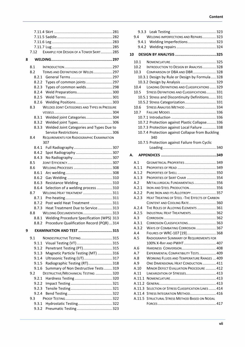
Figure 1-3: Vertical Drum on Leg Support [3]
Tower (Column)
Figure 1-4 illustrates a typical tall, vertical tower. Tall vertical towers are constructed in a wide range of shell diameters and heights. Towers can be relatively small in diameter and very tall (e.g., a 4 ft. diameter and 200 ft. tall distillation column), or very large in diameter and moderately tall (e.g., a 30 ft. diameter and 150 ft. tall pipestill tower). The shell sections of a tall tower may be constructed of different materials, thicknesses, and diameters. This is because temperature and phase changes of the process fluid which are the factors that affect the corrosiveness of the process fluid, vary along the tower’s length [3].
Figure 1-4: Tall Vertical Tower [3]
Reactor
Figure 1-5 illustrates a typical reactor vessel with a cylindrical shell. The process fluid undergoes a chemical reaction inside a reactor. This reaction is normally facili-tated by the presence of catalyst which is held in one or more catalyst beds [3].
Figure 1-5: Vertical Reactor [3]
Spherical Tank
Figure 1-6 shows a pressurized storage vessel with a spherical shell. Spherical tanks are usually used for gas storage under high pressure.
Figure 1-6: Spherical Pressurized Storage Tank [3]
General
5
1.3 Components of Pressure Vessels
The main pressure vessel components are as follow:
1.3.1 Shell
The shell is the primary component that contains the pressure. Pressure vessel shells are welded together to form a structure that has a common rotational axis. Most pressure vessel shells are cylindrical, spherical and conical in shape, which are discussed in detail on chapter 3 of this book.
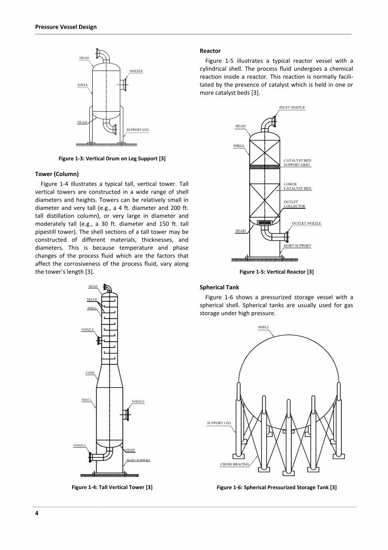
1.3.2 Head
All pressure vessel shells must be closed at the ends by heads (or another shell section). Heads are typically
curved rather than flat. Curved configurations are strong-er and allow the heads to be thinner, lighter, and less expensive than flat heads. Heads can also be used inside a vessel. These “intermediate heads” separate sections of the pressure vessel to permit different design conditions in each section [3]. Heads are usually categorized by their shapes. Ellipsoidal, hemispherical, torispherical, conical, toriconical and flat are the common types of heads which are discussed in detail on chapter 4 of this book. Figure 1-7 shows various types of heads. Ellipsoidal (2:1) would be the most common type of heads, which is used during the designing of pressure vessels.
Figure 1-7: Typical Types of Heads [4]
1.3.3 Nozzle
A nozzle is a cylindrical component that penetrates the shell or heads of a pressure vessel. The nozzle ends are usually flanged to allow for the necessary connections and to permit easy disassembly for maintenance or access. Nozzles are used for the following applications:
Attach piping for flow into or out of the vessel.
Attach instrument connections, (e.g., level gauges,
thermowells, or pressure gauges).
Provide access to the vessel interior at manways.
Provide for direct attachment of other equipment
items, (e.g., a heat exchanger or mixer).
Pressure Vessel Design
6
Nozzles are also sometimes extended into the vessel interior for some applications, such as for inlet flow distribution or to permit the entry of thermowells [3]. Design of openings and nozzles would be discussed on chapter 5 of this book.
1.3.4 Support
The type of support that is used depends primarily on the size and orientation of the pressure vessel. In all cases, the pressure vessel support must be adequate for the applied weight, wind, and earthquake loads [3]. Calculated base loads are used to design of anchorage and foundation for the pressure vessels. Supporting design would be discussed in detail on chapter 7 of this book. Typical kinds of supports are as follow:
a) Skirt
Tall, vertical, cylindrical pressure vessels (e.g., the tower and reactor shown in Figure 1-4 and Figure 1-5 respectively) are typically supported by skirts. A support skirt is a cylindrical shell section that is welded either to the lower portion of the vessel shell or to the bottom head (for cylindrical vessels). Skirts for spherical vessels are welded to the vessel near the mid-plane of the shell. The skirt is normally long enough to provide enough flexibility so that radial thermal expansion of the shell does not cause high thermal stresses at its junction with the skirt [3].
b) Leg
Small vertical drums (See Figure 1-3) are typically sup-ported on legs that are welded to the lower portion of the shell. The maximum ratio of support leg length to drum diameter is typically 2:1. The number of legs needed depends on the drum size and the loads to be carried. Support legs are also typically used for spherical pressurized storage vessels (See Figure 1-6). The support legs for small vertical drums and spherical pressurized storage vessels may be made from structural steel col-umns or pipe sections, whichever provides a more effi-cient design. Cross bracing between the legs, as shown in Figure 1.6, is typically used to help absorb wind or earth-quake loads [3].
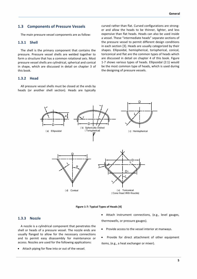
c) Saddle
Horizontal drums (See Figure 1-2) are typically sup-ported at two locations by saddle supports. A saddle support spreads the weight load over a large area of the shell to prevent an excessive local stress in the shell at the support points. The width of the saddle, among other design details, is determined by the specific size and design conditions of the pressure vessel. One saddle support is normally fixed or anchored to its foundation.
The other support is normally free to permit unrestrained longitudinal thermal expansion of the drum [3]. A typical scheme of saddle support is shown on Figure 1-8.
Figure 1-8: Typical Scheme of Saddle
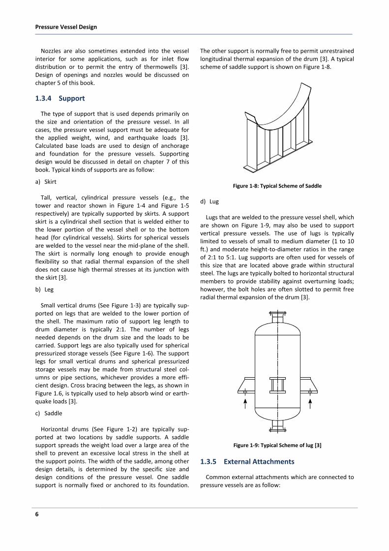
d) Lug
Lugs that are welded to the pressure vessel shell, which are shown on Figure 1-9, may also be used to support vertical pressure vessels. The use of lugs is typically limited to vessels of small to medium diameter (1 to 10 ft.) and moderate height-to-diameter ratios in the range of 2:1 to 5:1. Lug supports are often used for vessels of this size that are located above grade within structural steel. The lugs are typically bolted to horizontal structural members to provide stability against overturning loads; however, the bolt holes are often slotted to permit free radial thermal expansion of the drum [3].
Figure 1-9: Typical Scheme of lug [3]
1.3.5 External Attachments
Common external attachments which are connected to pressure vessels are as follow:
General
11
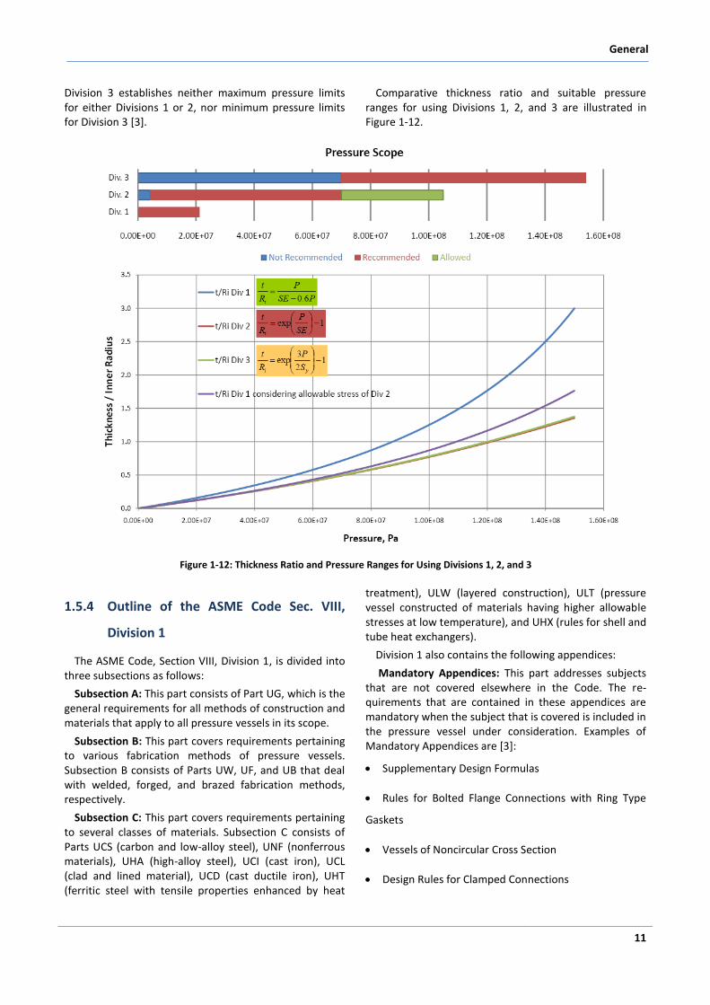
Division 3 establishes neither maximum pressure limits for either Divisions 1 or 2, nor minimum pressure limits for Division 3 [3].
Comparative thickness ratio and suitable pressure ranges for using Divisions 1, 2, and 3 are illustrated in Figure 1-12.
Figure 1-12: Thickness Ratio and Pressure Ranges for Using Divisions 1, 2, and 3
1.5.4 Outline of the ASME Code Sec. VIII,
Division 1
The ASME Code, Section VIII, Division 1, is divided into three subsections as follows:
Subsection A: This part consists of Part UG, which is the general requirements for all methods of construction and materials that apply to all pressure vessels in its scope.
Subsection B: This part covers requirements pertaining to various fabrication methods of pressure vessels. Subsection B consists of Parts UW, UF, and UB that deal with welded, forged, and brazed fabrication methods, respectively.
Subsection C: This part covers requirements pertaining to several classes of materials. Subsection C consists of Parts UCS (carbon and low-alloy steel), UNF (nonferrous materials), UHA (high-alloy steel), UCI (cast iron), UCL (clad and lined material), UCD (cast ductile iron), UHT (ferritic steel with tensile properties enhanced by heat
treatment), ULW (layered construction), ULT (pressure vessel constructed of materials having higher allowable stresses at low temperature), and UHX (rules for shell and tube heat exchangers).
Division 1 also contains the following appendices:
Mandatory Appendices: This part addresses subjects that are not covered elsewhere in the Code. The re-quirements that are contained in these appendices are mandatory when the subject that is covered is included in the pressure vessel under consideration. Examples of Mandatory Appendices are [3]:
Supplementary Design Formulas
Rules for Bolted Flange Connections with Ring Type
Gaskets
Vessels of Noncircular Cross Section
Design Rules for Clamped Connections
Material
23
2 Material
2.1 Introduction
The goal of this chapter is to give knowledge to engi-neers to select and specify the most economic material for pressure vessels considering requirement of the codes.
There are many parameters which may be investigated by practice, calculations and tests, shall be considered in the selection of suitable material for pressure vessels. These parameters are including the following aspects:
Strength for design condition
Strength for desired service life
Resistance to corrosion in service environment for desired life
Capabilities for fabrication processes
Market availability
Maintenance and repair
Cost (first investment and operation cost)
Thus, to achieve the goal, metallurgical fundamentals are initially reviewed. Afterwards, technical and com-mercial terms, definitions, and designations of materials are described. Finally, the code approach and require-ments for materials will be discussed. Introductions of metallurgical fundamentals and corrosion mechanisms are given in appendix 1 and appendix 2 respectively.
2.2 Material Standards
2.2.1 North American Metal Standard Desig-nation Systems
2.2.1.1 Introduction
In the world of standardization, metals pioneered the way at the turn of this century. In 1895, the French government assigned a commission to formulate stan-dard methods of testing materials of construction. Later that year, the European member countries of the Inter-national Association for Testing Materials (IATM) held their first conference in Zurich and standardization of metals began. Today, there are numerous national, continental, and international standards each with its own cryptic designation system to identify metals and their alloys. The evolution of the metals industry has left us with numerous designation systems, even within an individual standards organization, and these have be-come blurred and less meaningful as new generations of technical personnel are passed the torch to carry on the task of standardization [6].
By reviewing some examples of the more prominent metals designation systems, a direction is offered to assist those who use metal standards as a part of their work or study. This chapter is not all inclusive. The amount of information on this topic could easily make up a complete book [6].
Pressure Vessel Design
24
2.2.1.2 American Metal Standard Organizations
There are many metals standards organizations in the United States, a few of the more prominent ones are listed as follows:
AA The Aluminum Association
AISI American Iron and Steel Institute
ANSI American National Standards Institute
AMS Aerospace Material Specifications (SAE)
ASME American Society of Mechanical Engineers
ASTM American Society for Testing and Materials
AWS American Welding Society
CSA Canadian Standards Association
SAE Society of Automotive Engineers
For each North American organization issuing metal specifications and standards, there is a designation system used to identify various metal and alloys. These designation systems grew according to the history of each group, and generally identify a metal by use of a coded number or alphanumeric designator. In some cases, numbers and letters were assigned in a sequential order by the respective listing organization, while in other cases they were given in a manner which directly identified chemical composition or mechanical proper-ties. Some of the more popular North American designa-tion systems for metals are presented below, with descriptive examples given [6].
2.2.1.3 American Society for Testing and Materials (ASTM)
The first complete book of ASTM Standards was pub-lished in 1915. Today there are 69 ASTM books of stan-dards contained in 15 sections on various subjects. For the most part, the metals related standards are found in Section 1 - Iron and Steel Products (7 volumes), Section 2 - Nonferrous Metal Products (5 volumes), and Section 3 - Metals Test Methods and Analytical Procedures (6 volumes). These standards are revised yearly, as an example, from 1992 to 1993, 256 of the 631 standards was revised in Section 1 - Iron and Steel Products. Some standards (e.g. ASTM A 240) change several times a year and letter suffixes (a, b, c, etc.) are used to track mid-year revisions. This represents changes in 40% of these standards, not including the new standards that were issued that year. Consequently, it is an understatement to say that metal standards are very dynamic documents [6].
2.2.1.4 ASTM Specification System
Steel products are categorized according to designa-tion systems such as the AISI/SAE system or the UNS system described below, and also according to specifica-tion systems. These are statements of requirements, technical and commercial, that a product must meet, and therefore they can be used for purposes of pro-
curement. One widely used system of specifications has been developed by the ASTM. The designation consists of a letter (A for ferrous materials) followed by an arbitrary serially assigned number. These specifications often apply to specific products, for example A 548 is applicable to cold-heading quality carbon steel wire for tapping or sheet metal screws. Metric ASTM specifica-tions have a suffix letter M. Some ASTM specifications (e.g. bars, wires and billets for forging) incorporate AISI/SAE designations for composition while others (e.g. plates and structural shapes) specify composition limits and ranges directly. Such requirements as strength levels, manufacturing and finishing methods and heat treatments are frequently incorporated into the ASTM product specifications [6].
2.2.1.5 Ferrous Metal Definition
Prior to 1993 the ASTM definition for ferrous metals was based on nominal chemical composition, where an iron content of 50% or greater determined the alloy to be ferrous. Consequently, these standards begin with the letter "A". If the iron content was less than 50%, then the next abundant element would determine the type of nonferrous alloy. Generally these standards begin with the letter "B".
For example, should nickel be the next predominant element then the metal would be a nickel alloy. Current-ly, ASTM has adopted the European definition of steel described in the Euro Norm Standard CEN EN10020 - Definition and Classification of Steel, which defines steel as:
"A material which contains by weight more iron than any single element, having carbon content generally less than 2% and containing other elements. A limited num-ber of chromium steels may contain more than 2% of carbon, but 2% is the usual dividing line between steel and cast iron."
The CEN committee responsible for this standard has suggested changing the term "by weight" to "by mass" in order to stay consistent with the International System of Units [6].
2.2.1.6 ASTM Steels
Examples of the ASTM ferrous metal designation sys-tem, describing its use of specification numbers and letters, are as follows.
ASTM A 516/A 516M - 90 Grade 70 - Pressure Vessel Plates, Carbon Steel, for Moderate- and Lower-Temperature Service:
o The "A" describes a ferrous metal, but does not sub-classify it as cast iron, carbon steel, alloy steel or stain-less steel. o 516 is simply a sequential number without any direct relationship to the metal’s properties.
Material
25
o The "M" indicates that the standard A 516M is written in SI units (as a soft conversion) (the "M" comes from the word "Metric"), hence together A 516/A 516M utilizes both inch-pound and SI units. o 90 indicates the year of adoption or revision. o Grade 70 indicates the minimum tensile strength in ksi, i.e. 70 ksi (70,000 psi) minimum.
In the steel industry, the terms Grade, Type and Class have specific meaning. "Grade" is used to describe chemical composition, "Type" is used to define deoxida-tion practice, and "Class" is used to indicate other characteristics such as strength level or surface finish. However, within ASTM standards these terms were adapted for use to identify a particular metal within a metal standard and are used without any "strict" defini-tion, but essentially mean the same thing. Some rules-of-thumb do exist, with a few examples as follows.
ASTM A 106 - 91 Grade A, Grade B, Grade C - Seam-less Carbon Steel Pipe for High-Temperature Service:
o Typically an increase in alphabet (such as the letters A, B, C) results in higher strength (tensile or yield) steels, and if it is an unalloyed carbon steel, an increase in carbon content. in this case: Grade A - 0.25%C (max.), 48 ksi tensile strength (min.); Grade B - 0.30%C (min.), 60 ksi tensile strength (min.); Grade C - 0.35%C 70 ksi tensile strength (min.).
ASTM A 48 - Class No. 20A, 25A, 30A - Gray Iron Castings:
o Class No. 20A describes this cast iron material as having a minimum tensile strength of 20 ksi (20,000 psi). o Similarly Class No. 25A has a minimum tensile strength of 25 ksi and Class No. 30A has a minimum tensile strength of 30 ksi.
ASTM A 276 Type 304, 316, and 410 - Stainless and Heat-Resisting Steel Bars and Shapes:
Types 304, 316, 410 and others are based on the AISI designation system for stainless steels (see AISI descrip-tion that follows).
Some ASTM standards will use more than one term to describe an individual metal within a group of metals from one standard, as shown in the following example.
ASTM A 193/193M-94 - Alloy Steel and Stainless Steel Bolting Materials for High Temperature Service:
o Uses the terms “Type”, “Identification Symbol”, “Grade” and “Class” to describe bolting materials. o Example, Type: Austenitic steel, Identification Sym-bol: B8, Grade: Unstabilized 18 Chromium - 8 Nickel (AISI Type 304), is available in four different Classes: 1, 1A, 1D, and 2.
The ASTM designation system for cast stainless steels was adopted from the Alloy Casting Institute (ACI) system. According to this system, the designation con-sists of two letters followed by two digits and then optional suffix letters. The first letter of the designation is "C", if the alloy is intended for liquid corrosion service,
or "H", for high temperature service. A second letter refers to the chromium and nickel contents of the alloy, increasing with increasing nickel content. The two letters are then followed by a number which gives the carbon content in hundredths of a percent and in some cases a suffix letter or letters to indicate the presence of other alloying elements. It is important to note that the vari-ous casting grades of these stainless steels have a unique designation system different from that of their wrought counterparts.
For example, the designation "cast 304" stainless steel does not exist within the ASTM (ACI) system and is appropriately called grade CF8. Other examples are as follows.
ASTM A 351 Grade CF8M, Grade HK40 - Castings, Austenitic, Austenitic-Ferritic (Duplex), for Pressure Containing Parts:
o The "C" in CF8M indicates a Corrosion resistant metal and the "H" in HK40 indicates a Heat resistant metal. o The numeric portion of the corrosion resistant designations represents the maximum carbon content multipled by 100, and those of the heat resistant desig-nations represent its nominal carbon content multiplied by 100. For example: the maximum carbon content of grade CF8M is 0.08% C and the nominal carbon content of grade HK40 is 0.40%C (its actual carbon content range is 0.35-0.45%C). o The "M" after the number represents an intentional addition of Molybdenum.
An interesting use of ASTM grade designators is found in pipe, tube and forging products, where the first letter "P" refers to pipe, "T" refers to tube, "TP" may refer to tube or pipe, and "F" refers to forging. Examples are found in the following ASTM specifications:
ASTM A 335/A 335M - 91 grade P22 - Seamless Ferritic Alloy-Steel Pipe for High-Temperature Service.
ASTM A 213/A 213M - 91 grade T22 - Seamless Ferritic and Austenitic Alloy-Steel Boiler, Superheater, and Heat-Exchanger Tubes.
ASTM A 269 - 90 grade TP304 - Seamless and Welded Austenitic Stainless Steel Tubing for General Service.
ASTM A 312/A 312M - 91 grade TP304 - Seamless and Welded Austenitic Stainless Steel Pipes.
ASTM A 336/A 336M - 89 class F22 - Steel Forgings, Alloy, for Pressure and High-Temperature Parts [6].
2.2.1.7 ASTM Reference Standards and Supplemen-tary Requirements
ASTM Standards contain a section known as "Refer-ence Documents" that lists other ASTM Standards that either becomes a part of the original standard or its supplementary requirements. Supplementary require-ments are listed at the end of the ASTM Standards and do not apply unless specified in the order, i.e. they are optional [6].
Material
43
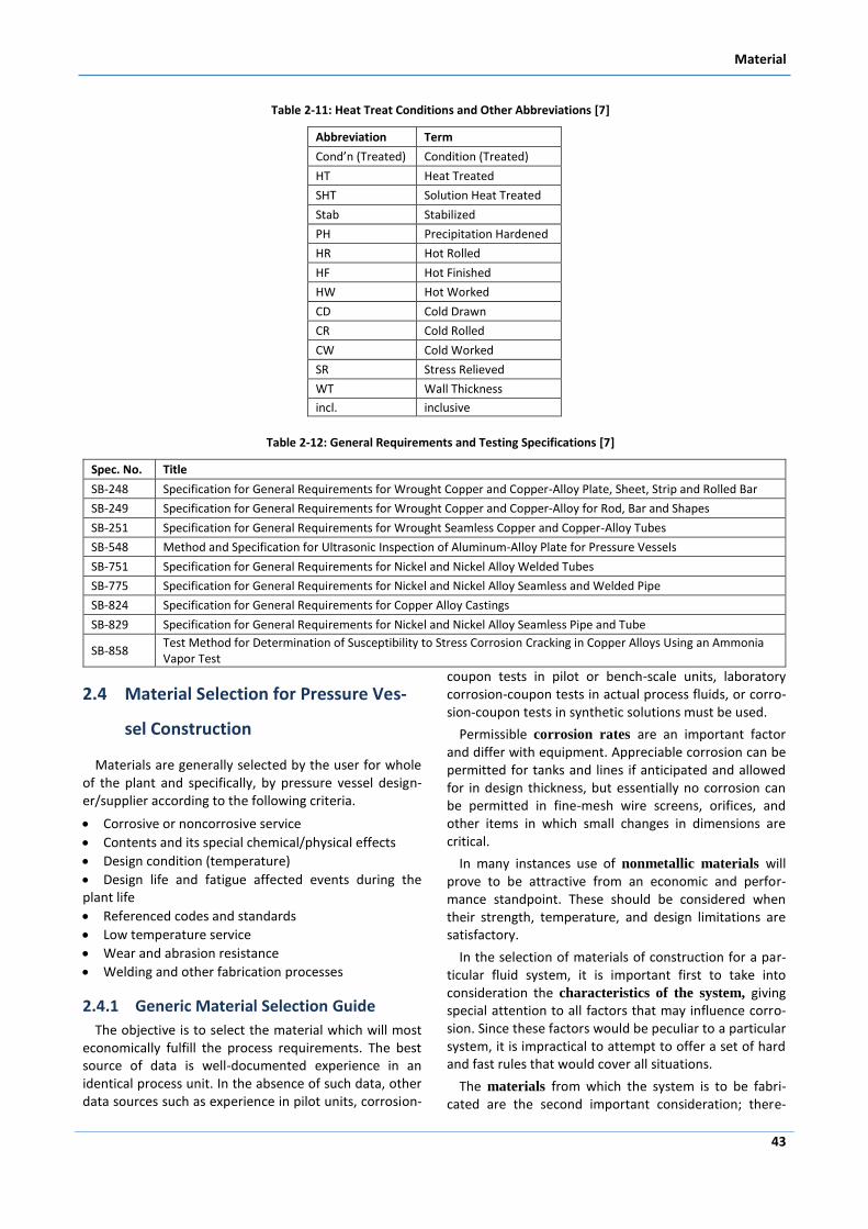
Table 2-11: Heat Treat Conditions and Other Abbreviations [7]
Abbreviation Term
Cond’n (Treated) Condition (Treated)
HT Heat Treated
SHT Solution Heat Treated
Stab Stabilized
PH Precipitation Hardened
HR Hot Rolled
HF Hot Finished
HW Hot Worked
CD Cold Drawn
CR Cold Rolled
CW Cold Worked
SR Stress Relieved
WT Wall Thickness
incl. inclusive
Table 2-12: General Requirements and Testing Specifications [7]
Spec. No. Title
SB-248 Specification for General Requirements for Wrought Copper and Copper-Alloy Plate, Sheet, Strip and Rolled Bar
SB-249 Specification for General Requirements for Wrought Copper and Copper-Alloy for Rod, Bar and Shapes
SB-251 Specification for General Requirements for Wrought Seamless Copper and Copper-Alloy Tubes
SB-548 Method and Specification for Ultrasonic Inspection of Aluminum-Alloy Plate for Pressure Vessels
SB-751 Specification for General Requirements for Nickel and Nickel Alloy Welded Tubes
SB-775 Specification for General Requirements for Nickel and Nickel Alloy Seamless and Welded Pipe
SB-824 Specification for General Requirements for Copper Alloy Castings
SB-829 Specification for General Requirements for Nickel and Nickel Alloy Seamless Pipe and Tube
SB-858 Test Method for Determination of Susceptibility to Stress Corrosion Cracking in Copper Alloys Using an Ammonia Vapor Test
2.4 Material Selection for Pressure Ves-
sel Construction
Materials are generally selected by the user for whole of the plant and specifically, by pressure vessel design-er/supplier according to the following criteria.
Corrosive or noncorrosive service
Contents and its special chemical/physical effects
Design condition (temperature)
Design life and fatigue affected events during the plant life
Referenced codes and standards
Low temperature service
Wear and abrasion resistance
Welding and other fabrication processes
2.4.1 Generic Material Selection Guide
The objective is to select the material which will most economically fulfill the process requirements. The best source of data is well-documented experience in an identical process unit. In the absence of such data, other data sources such as experience in pilot units, corrosion-
coupon tests in pilot or bench-scale units, laboratory corrosion-coupon tests in actual process fluids, or corro-sion-coupon tests in synthetic solutions must be used.
Permissible corrosion rates are an important factor and differ with equipment. Appreciable corrosion can be permitted for tanks and lines if anticipated and allowed for in design thickness, but essentially no corrosion can be permitted in fine-mesh wire screens, orifices, and other items in which small changes in dimensions are critical.
In many instances use of nonmetallic materials will prove to be attractive from an economic and perfor-mance standpoint. These should be considered when their strength, temperature, and design limitations are satisfactory.
In the selection of materials of construction for a par-ticular fluid system, it is important first to take into consideration the characteristics of the system, giving special attention to all factors that may influence corro-sion. Since these factors would be peculiar to a particular system, it is impractical to attempt to offer a set of hard and fast rules that would cover all situations.
The materials from which the system is to be fabri-cated are the second important consideration; there-
Pressure Vessel Design
56
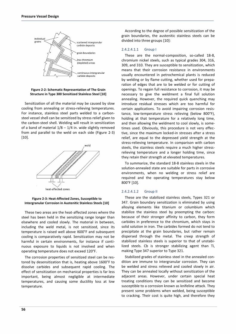
Figure 2-2: Schematic Representation of The Grain Structure in Type 300 Sensitized Stainless Steel [10]
Sensitization of all the material may be caused by slow cooling from annealing or stress-relieving temperatures. For instance, stainless steel parts welded to a carbon-steel vessel shell can be sensitized by stress relief given to the carbon-steel shell. Welding will result in sensitization of a band of material 1/8 – 1/4 in. wide slightly removed from and parallel to the weld on each side (Figure 2-3) [10].
Figure 2-3: Heat-Affected Zones, Susceptible to Intergranular Corrosion in Austenitic Stainless Steels [10]
These two areas are the heat-affected zones where the steel has been held in the sensitizing range longer than elsewhere and cooled slowly. The material in between, including the weld metal, is not sensitized, since its temperature is raised well above I600°F and subsequent cooling is comparatively rapid. Sensitization may not be harmful in certain environments, for instance if conti-nuous exposure to liquids is not involved and when operating temperature does not exceed 120°F.
The corrosion properties of sensitized steel can be res-tored by desensitization that is, heating above 1600°F to dissolve carbides and subsequent rapid cooling. The effect of sensitization on mechanical properties is far less important, being almost negligible at intermediate temperatures, and causing some ductility loss at low temperature.
According to the degree of possible sensitization of the grain boundaries, the austenitic stainless steels can be divided into three groups [10]:
2.4.2.4.1.1 Group I
These are the normal-composition, so-called 18-8, chromium nickel steels, such as typical grades 304, 316, 309, and 310. They are susceptible to sensitization, which means that their corrosion resistance in environments usually encountered in petrochemical plants is reduced by welding or by flame cutting, whether used for prepa-ration of edges that are to be welded or for cutting of openings. To regain full resistance to corrosion, it may be necessary to give the weldment a final full solution annealing. However, the required quick quenching may introduce residual stresses which are too harmful for certain applications. To avoid impairing corrosion resis-tance, low-temperature stress relieving (below 800°F), holding at that temperature for a relatively long time, and then allowing the weldment to cool slowly, is some-times used. Obviously, this procedure is not very effec-tive, since the maximum locked-in stresses after a stress relief, are equal to the depressed yield strength at the stress-relieving temperature. In comparison with carbon steels, the stainless steels require a much higher stress-relieving temperature and a longer holding time, since they retain their strength at elevated temperatures.
To summarize, the standard 18-8 stainless steels in the solution-annealed state are suitable for parts in corrosive environments, when no welding or stress relief are required and the operating temperatures stay below 800°F [10].
2.4.2.4.1.2 Group II
These are the stabilized stainless steels, Types 321 or 347. Grain boundary sensitization is eliminated by using alloying elements like titanium or columbium which stabilize the stainless steel by preempting the carbon: because of their stronger affinity to carbon, they form carbides in preference to the chromium, which stays in solid solution in iron. The carbides formed do not tend to precipitate at the grain boundaries, but rather remain dispersed through the metal. The creep strength of stabilized stainless steels is superior to that of unstabi-lized steels. Cb is stronger stabilizing agent than Ti, making Type 347 superior to Type 321.
Stabilized grades of stainless steel in the annealed con-dition are immune to intergranular corrosion. They can be welded and stress relieved and cooled slowly in air. They can be annealed locally without sensitization of the adjacent areas. However, under certain special heat treating conditions they can be sensitized and become susceptible to a corrosion known as knifeline attack. They present some problems when welded, being susceptible to cracking. Their cost is quite high, and therefore they
Material
57
are used only for special jobs, such as for operating temperatures above 800°F. They also tend to lose their immunity to intergranular corrosion when their surfaces are carburized by the process environment [10].
2.4.2.4.1.3 Group III
These are extra-low-carbon grades like 304L or 316L. Grain boundary sensitization can be minimized by using low-carbon stainless steels with 0.03 percent C maxi-mum, at the expense of lowered strength. The rate of chromium carbide precipitation is so retarded that they can be held within the 800-1500°F range for up to several hours without damage to their corrosion resistance.
Extra-low-carbon stainless steels can be stress relieved, welded, and slowly cooled without significantly increas-ing their susceptibility to intergranular attack. They are very often used in pressure vessel construction, either as solid plate or for internal lining material. They are more expensive than normal-composition stainless steels because of the difficulty and cost of removing the carbon. However, they are not equivalent to group II, since they are subject to sensitization if the operating temperature remains in the 800-1 500°F range for a prolonged period of time. Consequently, the extra-low-carbon grades can be used for applications at operating temperatures up to 800°F [10].
2.4.2.4.2 Ferritic Stainless Steels
Ferritic stainless steels usually include straight chro-mium stainless steels with 16-30 percent chromium. They are nonhardenable by heat treatment. A typical stainless steel of this group is type 430. The grade quite often used for corrosion resistant cladding or lining is type 405, which contains only 12 percent chromium; however, addition of aluminum renders it ferritic and nonhardena-ble. When type 405 cools from high welding tempera-tures there is no general transformation from austenite to martensite and it does not harden in air. However, it may become brittle in heat-affected zones because of rapid grain growth. Ferritic steels may become notch sensitive in heat-affected weld zones, and they are also susceptible to intergranular corrosion. Ferritic stainless steels are sensitized by heating to a temperature of I1700°F and then air cooled at normal rates. If they are cooled slowly (in a furnace) their resistance to intergra-nular corrosion is preserved. Annealing of a sensitized ferritic stainless steel at 1450°F allows chromium to diffuse into depleted parts to restore the corrosion resistance.
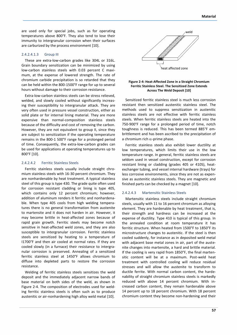
Welding of ferritic stainless steels sensitizes the weld deposit and the immediately adjacent narrow bands of base material on both sides of the weld, as shown in Figure 2-4. The composition of electrodes used for weld-ing ferritic stainless steels is often such as to produce austenitic or air-nonhardening high alloy weld metal [10].
Figure 2-4: Heat-Affected Zone in a Straight Chromium Ferritic Stainless Steel. The Sensitized Zone Extends
Across The Weld Deposit [10]
Sensitized ferritic stainless steel is much less corrosion resistant then sensitized austenitic stainless steel. The methods used to suppress sensitization in austenitic stainless steels are not effective with ferritic stainless steels. When ferritic stainless steels are heated into the 750-900°F range for a prolonged period of time, notch toughness is reduced. This has been termed 885°F em-brittlement and has been ascribed to the precipitation of
a chromium rich -prime phase.
Ferritic stainless steels also exhibit lower ductility at low temperatures, which limits their use in the low temperature range. In general, ferritic stainless steels are seldom used in vessel construction, except for corrosion resistant lining or cladding (grades 405 or 410S), heat-exchanger tubing, and vessel internal hardware (trays) for less corrosive environments, since they are not as expen-sive as austenitic stainless steels. They are magnetic and finished parts can be checked by a magnet [10].
2.4.2.4.3 Martensitic Stainless Steels
Martensitic stainless steels include straight chromium steels, usually with 11 to 16 percent chromium as alloying element. They are hardenable by heat treatment, that is, their strength and hardness can be increased at the expense of ductility. Type 410 is typical of this group. In the annealed condition at room temperature it has ferritic structure. When heated from 1500°F to 1850°F its microstructure changes to austenitic. If the steel is then cooled suddenly, for instance as in deposited weld metal with adjacent base metal zones in air, part of the auste-nite changes into martensite, a hard and brittle material. If the cooling is very rapid from 1850°F, the final marten-sitic content will be at a maximum. Post-weld heat treatment with controlled cooling will reduce residual stresses and will allow the austenite to transform to ductile ferrite. With normal carbon content, the harde-nability of straight chromium stainless steels is markedly reduced with above 14 percent chromium. With in-creased carbon content, they remain hardenable above 14 percent up to 18 percent chromium. With 18 percent chromium content they become non-hardening and their
Pressure Vessel Design
62
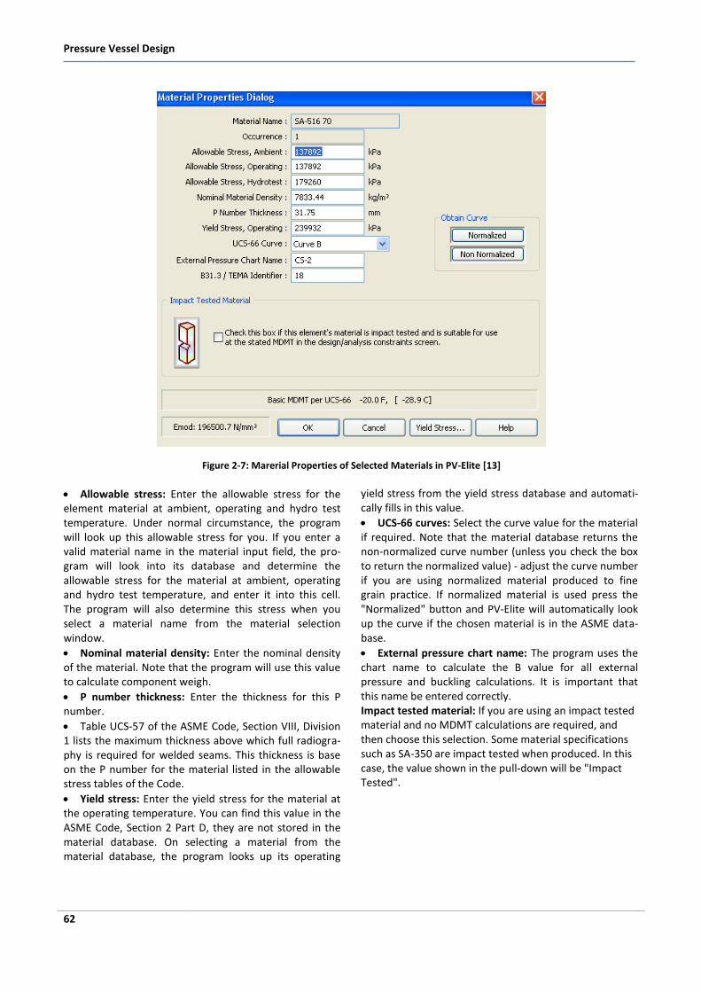
Figure 2-7: Marerial Properties of Selected Materials in PV-Elite [13]
Allowable stress: Enter the allowable stress for the element material at ambient, operating and hydro test temperature. Under normal circumstance, the program will look up this allowable stress for you. If you enter a valid material name in the material input field, the pro-gram will look into its database and determine the allowable stress for the material at ambient, operating and hydro test temperature, and enter it into this cell. The program will also determine this stress when you select a material name from the material selection window.
Nominal material density: Enter the nominal density of the material. Note that the program will use this value to calculate component weigh.
P number thickness: Enter the thickness for this P number.
Table UCS-57 of the ASME Code, Section VIII, Division 1 lists the maximum thickness above which full radiogra-phy is required for welded seams. This thickness is base on the P number for the material listed in the allowable stress tables of the Code.
Yield stress: Enter the yield stress for the material at the operating temperature. You can find this value in the ASME Code, Section 2 Part D, they are not stored in the material database. On selecting a material from the material database, the program looks up its operating
yield stress from the yield stress database and automati-cally fills in this value.
UCS-66 curves: Select the curve value for the material if required. Note that the material database returns the non-normalized curve number (unless you check the box to return the normalized value) - adjust the curve number if you are using normalized material produced to fine grain practice. If normalized material is used press the "Normalized" button and PV-Elite will automatically look up the curve if the chosen material is in the ASME data-base.
External pressure chart name: The program uses the chart name to calculate the B value for all external pressure and buckling calculations. It is important that this name be entered correctly. Impact tested material: If you are using an impact tested material and no MDMT calculations are required, and then choose this selection. Some material specifications such as SA-350 are impact tested when produced. In this case, the value shown in the pull-down will be "Impact Tested".
Shell Design
63
3 Shell Design
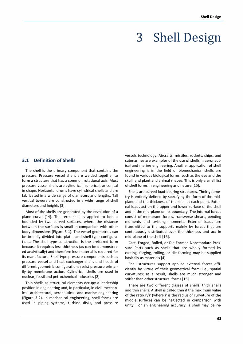
3.1 Definition of Shells
The shell is the primary component that contains the pressure. Pressure vessel shells are welded together to form a structure that has a common rotational axis. Most pressure vessel shells are cylindrical, spherical, or conical in shape. Horizontal drums have cylindrical shells and are fabricated in a wide range of diameters and lengths. Tall vertical towers are constructed in a wide range of shell diameters and heights [3].
Most of the shells are generated by the revolution of a plane curve [14]. The term shell is applied to bodies bounded by two curved surfaces, where the distance between the surfaces is small in comparison with other body dimensions (Figure 3-1). The vessel geometries can be broadly divided into plate- and shell-type configura-tions. The shell-type construction is the preferred form because it requires less thickness (as can be demonstrat-ed analytically) and therefore less material is required for its manufacture. Shell-type pressure components such as pressure vessel and heat exchanger shells and heads of different geometric configurations resist pressure primar-ily by membrane action. Cylindrical shells are used in nuclear, fossil and petrochemical industries [2].
Thin shells as structural elements occupy a leadership position in engineering and, in particular, in civil, mechan-ical, architectural, aeronautical, and marine engineering (Figure 3-2). In mechanical engineering, shell forms are used in piping systems, turbine disks, and pressure
vessels technology. Aircrafts, missiles, rockets, ships, and submarines are examples of the use of shells in aeronaut-ical and marine engineering. Another application of shell engineering is in the field of biomechanics: shells are found in various biological forms, such as the eye and the skull, and plant and animal shapes. This is only a small list of shell forms in engineering and nature [15].
Shells are curved load-bearing structures. Their geome-try is entirely defined by specifying the form of the mid-plane and the thickness of the shell at each point. Exter-nal loads act on the upper and lower surface of the shell and in the mid-plane on its boundary. The internal forces consist of membrane forces, transverse shears, bending moments and twisting moments. External loads are transmitted to the supports mainly by forces that are continuously distributed over the thickness and act in mid-plane of the shell [16].
Cast, Forged, Rolled, or Die Formed Nonstandard Pres-sure Parts such as shells that are wholly formed by casting, forging, rolling, or die forming may be supplied basically as materials [4].
Shell structures support applied external forces effi-ciently by virtue of their geometrical form, i.e., spatial curvatures; as a result, shells are much stronger and stiffer than other structural forms [15].
There are two different classes of shells: thick shells and thin shells. A shell is called thin if the maximum value of the ratio (where is the radius of curvature of the middle surface) can be neglected in comparison with unity. For an engineering accuracy, a shell may be re-
Pressure Vessel Design
66
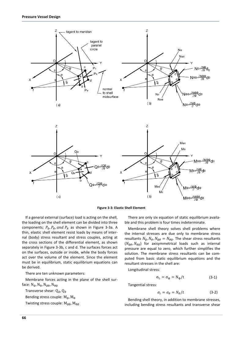
Figure 3-3: Elastic Shell Element
If a general external (surface) load is acting on the shell, the loading on the shell element can be divided into three components; as shown in Figure 3-3a. A thin, elastic shell element resist loads by means of inter-nal (body) stress resultant and stress couples, acting at the cross sections of the differential element, as shown separately in Figure 3-3b, c and d. The surfaces forces act on the surfaces, outside or inside, while the body forces act over the volume of the element. Since the element must be in equilibrium, static equilibrium equations can be derived.
There are ten unknown parameters:
Membrane forces acting in the plane of the shell sur-face:
Transverse shear:
Bending stress couple:
Twisting stress couple:
There are only six equation of static equilibrium availa-ble and this problem is four times indeterminate.
Membrane shell theory solves shell problems where the internal stresses are due only to membrane stress resultants . The shear stress resultants ( ) for axisymmetrical loads such as internal pressure are equal to zero, which further simplifies the solution. The membrane stress resultants can be com-puted from basic static equilibrium equations and the resultant stresses in the shell are:
Longitudinal stress:
(3-1)
Tangential stress:
(3-2)
Bending shell theory, in addition to membrane stresses, including bending stress resultants and transverse shear
Shell Design
67
forces (Figure 3-3 c). Here the number of unknowns exceeds the number of static equilibrium conditions and additional differential equations have to be derived from the deformation relations. Once the membrane stress resultants and and the resultant moments and
are determined the stresses in shell are:
Longitudinal stress:
(3-3)
Tangential stress:
(3-4)
Shear stress:
(3-5)
In the development of thin shell theories, simplification is accomplished by reducing the shell problems to the study of deformations of the middle surface.
A theory that takes into account finite or large defor-mations is referred to as a geometrically nonlinear theory of thin shells. Additionally, a shell may be physically nonlinear with respect to the stress–strain relations. In this case, the efficiency of thin shells can be reduced considerably.
To avoid the possibility of buckling, a shell structure should be designed in such a way that a dominant part of the structure is in tension [15].
3.3 ASME Code & Handbooks Formulas
3.3.1 Nomenclature Longitudinal/meridional stress (MPa) circumferential/latitudinal stress (MPa)
radial stress (MPa) Membrane forces acting in the plane of the shell surface (N) Transverse shear (MPa) Bending stress couple (MPa) Twisting stress couple (MPa) Joint efficiency for, or the efficiency of, appropriate joint in cylindrical or spherical shells, or the efficiency
of ligaments between openings, whichever is less. Internal design pressure (see [4] UG-21) (MPa) Outside radius of the shell course under consideration (mm) Maximum allowable stress value (see [4] UG-23 and the stress limitations specified in [4] UG-24) (MPa) Minimum required thickness of shell (mm) Factor determined from Figure 3-9 and used to enter the applicable material chart in Subpart 3 of Section
II, Part D. For the case of cylinders having
values less than 10, see [4] UG-28(c) (2).
Factor determined from the applicable material chart or table in Subpart 3 of Section II, Part D for maxi-mum design metal temperature [see [4] UG-20(c)]
outside diameter of cylindrical shell course or tube (mm) Modulus of elasticity of material at design temperature. For external pressure design in accordance with
this Section, the modulus of elasticity to be used shall be taken from the applicable materials chart in Subpart 3 of Section II, Part D. (Interpolation may be made between lines for intermediate temperatures.) (MPa)
Total length, of a tube between tube sheets, or design length of a vessel section between lines of support (see Figure 3-4) (mm)
external design pressure (MPa) Calculated value of maximum allowable external working pressure for the assumed value of . (MPa) outside radius of spherical shell (mm) Minimum required thickness of cylindrical shell or tube, or spherical shell (mm) nominal thickness of cylindrical shell or tube (mm) cross-sectional area of the stiffening ring (mm
2)
available moment of inertia of the stiffening ring cross section about its neutral axis parallel to the axis of the shell (mm
4)
Available moment of inertia of combined shell-cone or ring-shell-cone cross section about its neutral axis parallel to the axis of the shell. The nominal shell thickness shall be used, and the width of the shell which is taken as contributing to the moment of inertia of the combined section shall not be greater than
and shall be taken as lying one-half on each side of the cone-to- cylinder junction or of the
centroid of the ring. Portions of the shell plate shall not be considered as contributing area to more than one stiffening ring. (mm
4)
required moment of inertia of the stiffening ring cross section about its neutral axis parallel to the axis of
Pressure Vessel Design
68
the shell (mm4)
required moment of inertia of the combined shell-cone or ring-shell-cone cross section about its neutral
axis parallel to the axis of the shell (mm4)
one-half of the distance from the centerline of the stiffening ring to the next line of support on one side, plus one-half of the centerline distance to the next line of support on the other side of the stiffening ring, both measured parallel to the axis of the cylinder. (mm)
3.3.2 Cylindrical Shell under Internal Pressure
These formulas related to the ASME Code Section VIII, Division 1 that applies for pressures that exceed 15 psi (100 KPa) and through 3,000 psi (20 MPa). At pressures below 15 psi (100 KPa), the ASME Code is not applicable. At pressures above 3,000 psi (20 MPa), additional design rules are required to cover the design and construction requirements that are needed at such high pressures at ASME Code Section VIII, Division 2 that will be explained in detail in chapter 10.
The idealized equations for the calculation of hoop and longitudinal stresses, respectively, in a cylindrical shell under internal pressure are as follows:
(3-6)
(3-7)
These equations assume a uniform stress distribution through the thickness of the shell. Note that the longitu-dinal stress is half the hoop stress. Since this is an idea-lized state, the ASME Code formulas have been modified to account for no ideal behavior that is mentioned below.
The minimum required thickness of shells under inter-nal pressure shall not be less than that computed by the following formulas. In addition, provision shall be made for any of the loadings listed in [4] UG-22, when such loadings are expected. The provided thickness of the shells shall also meet the requirements of [4] UG-16, except as permitted in [4] Appendix 32.
The symbols defined below are used in the formulas of inside dimensions at this paragraph.
For welded vessels, use the efficiency specified in [4] UW-12.
For ligaments between openings, use the efficiency calculated by the rules given in [4] UG-53.
The minimum thickness or maximum allowable working pressure of cylindrical shells shall be the greater thickness or lesser pressure as given by (1) or (2) below.
1. Circumferential Stress (Longitudinal Joints):
When the thickness does not exceed one-half of the inside radius, or P does not exceed 0.385SE, the following formulas shall apply:
(3-8)
Or
(3-9)
2. Longitudinal Stress (Circumferential Joints):
When the thickness does not exceed one-half of the inside radius, or P does not exceed 1.25SE, the following formulas shall apply:
(3-10)
Or
(3-11)
These formulas will govern only when the circumferen-tial joint efficiency is less than one-half the longitudinal joint efficiency, or when the effect of supplementary loadings ( [4] UG-22) causing longitudinal bending or tension in conjunction with internal pressure is being investigated [4].
Usually the stress in the long seam is governing.
When the wall thickness exceeds one half of the inside radius or P exceeds 0.385 SE, the formulas given in the Code [4] Appendix 1-2 shall be applied [14].
When necessary, vessels shall be provided with stiffen-ers or other additional means of support to prevent overstress or large distortions under the external load-ings listed in [4] UG-22 other than pressure and tempera-ture.
A stayed jacket shell that extends completely around a cylindrical or spherical vessel shall also meet the re-quirements of [4] UG-47(c).
Any reduction in thickness within a shell course or spherical shell shall be in accordance with [4] UW-9 [4].
The internal pressure at which the weakest element of the vessel is loaded to the ultimate permissible point, when the vessel is assumed to be [14]:
In corroded condition
Under the effect of a designated temperature
In normal operating position at the top
Under the effect of other loadings (wind load, exter-nal pressure, hydrostatic pressure, etc.) which are addi-tive to the internal pressure.
The symbols defined below are used in the formulas of outside dimensions at this paragraph.
Pressure Vessel Design
74
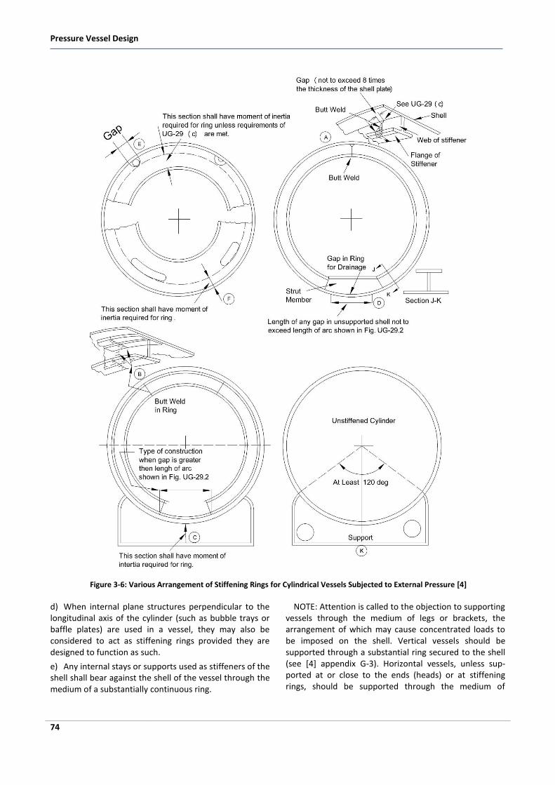
Figure 3-6: Various Arrangement of Stiffening Rings for Cylindrical Vessels Subjected to External Pressure [4]
d) When internal plane structures perpendicular to the longitudinal axis of the cylinder (such as bubble trays or baffle plates) are used in a vessel, they may also be considered to act as stiffening rings provided they are designed to function as such.
e) Any internal stays or supports used as stiffeners of the shell shall bear against the shell of the vessel through the medium of a substantially continuous ring.
NOTE: Attention is called to the objection to supporting vessels through the medium of legs or brackets, the arrangement of which may cause concentrated loads to be imposed on the shell. Vertical vessels should be supported through a substantial ring secured to the shell (see [4] appendix G-3). Horizontal vessels, unless sup-ported at or close to the ends (heads) or at stiffening rings, should be supported through the medium of
Pressure Vessel Design
102
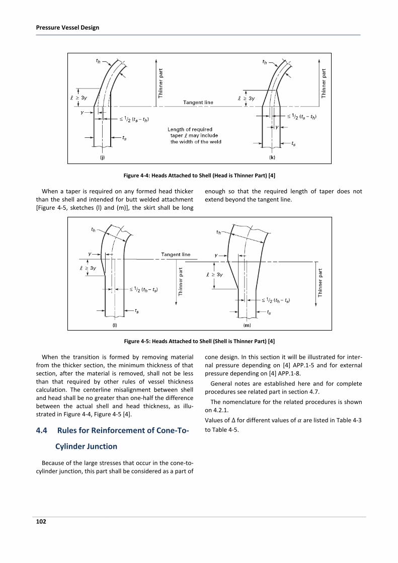
Figure 4-4: Heads Attached to Shell (Head is Thinner Part) [4]
When a taper is required on any formed head thicker than the shell and intended for butt welded attachment [Figure 4-5, sketches (l) and (m)], the skirt shall be long
enough so that the required length of taper does not extend beyond the tangent line.
Figure 4-5: Heads Attached to Shell (Shell is Thinner Part) [4]
When the transition is formed by removing material from the thicker section, the minimum thickness of that section, after the material is removed, shall not be less than that required by other rules of vessel thickness calculation. The centerline misalignment between shell and head shall be no greater than one-half the difference between the actual shell and head thickness, as illu-strated in Figure 4-4, Figure 4-5 [4].
4.4 Rules for Reinforcement of Cone-To-
Cylinder Junction
Because of the large stresses that occur in the cone-to-cylinder junction, this part shall be considered as a part of
cone design. In this section it will be illustrated for inter-nal pressure depending on [4] APP.1-5 and for external pressure depending on [4] APP.1-8.
General notes are established here and for complete procedures see related part in section 4.7.
The nomenclature for the related procedures is shown on 4.2.1.
Values of for different values of are listed in Table 4-3
to Table 4-5.
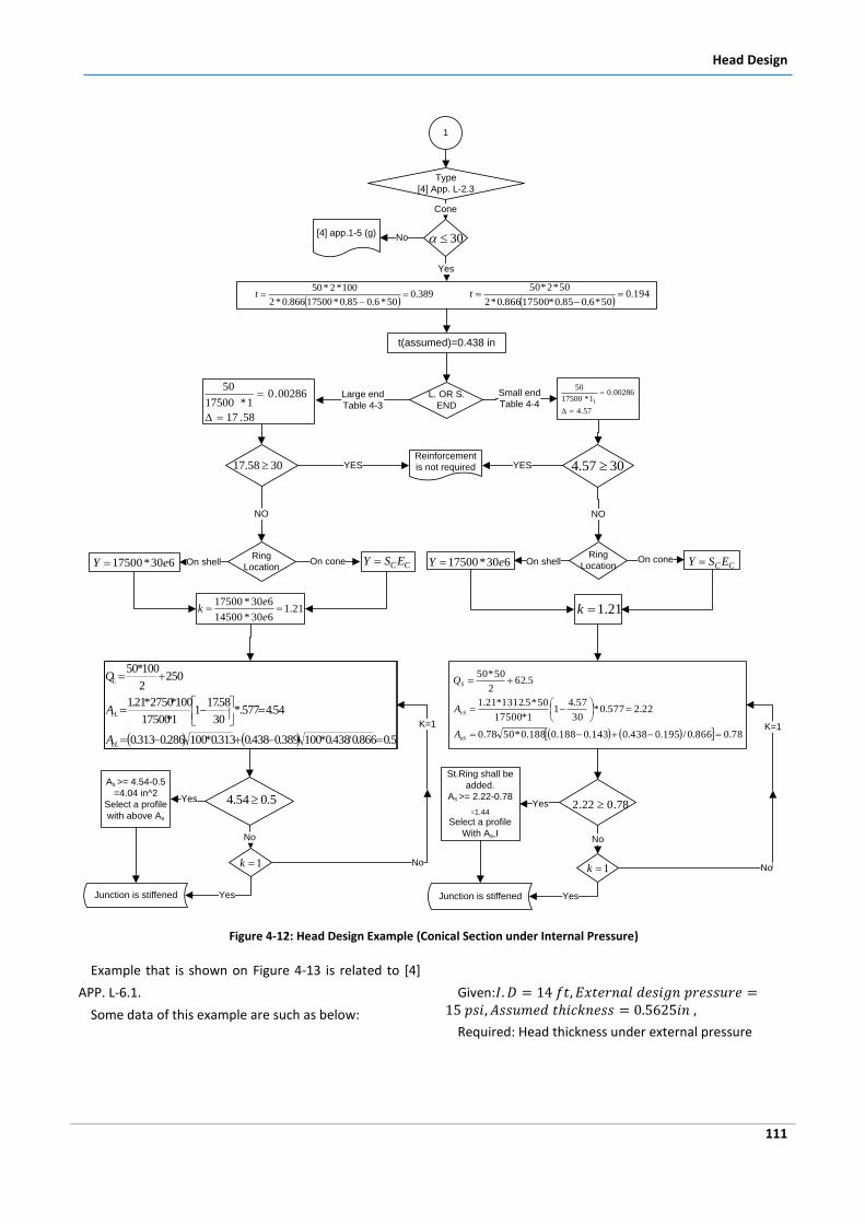
Head Design
111
Type
[4] App. L-2.3
Cone
30
Yes
[4] app.1-5 (g)No
389.0
50*6.085.0*17500866.0*2
100*2*50
t
L. OR S.
END
Large end
Table 4-3
Small end
Table 4-4
58.17
00286.01*17500
50
Reinforcement
is not requiredYES YES
Ring
LocationOn shell On cone
5.0866.0/438.0*100389.0438.0313.0*100286.0313.0
54.4577.*30
58.171
1*17500
100*2750*21.1
2502
100*50
eL
rL
L
A
A
Q
5.054.4
As >= 4.54-0.5
=4.04 in^2
Select a profile
with above As
Yes
No
Ring
LocationOn shell On cone
78.0866.0/195.0438.0143.0188.0188.0*5078.0
22.2577.0*30
57.41
1*17500
50*5.1312*21.1
5.622
50*50
eS
rS
S
A
A
Q
78.022.2
St.Ring shall be
added.
As >= 2.22-0.78
=1.44
Select a profile
With As,I
Yes
No
YesYes
No1k
21.1630*14500
630*17500
e
ek
NO NO
Junction is stiffened Junction is stiffened
1
t(assumed)=0.438 in
194.0
50*6.085.0*17500866.0*2
50*2*50
t
1k
CCESY 630*17500 eY CC ESY 630*17500 eY
3058.17
57.4
00286.01*17500
50
1
3057.4
21.1k
K=1
No
K=1
Figure 4-12: Head Design Example (Conical Section under Internal Pressure)
Example that is shown on Figure 4-13 is related to [4]
APP. L-6.1.
Some data of this example are such as below:
Given:
Required: Head thickness under external pressure
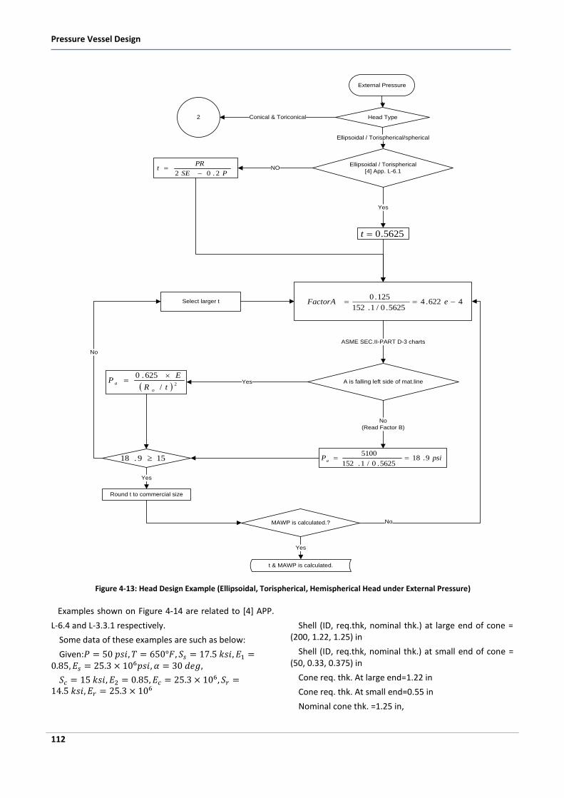
Pressure Vessel Design
112
5625.0t
4622.45625.0/1.152
125.0 eFactorA
A is falling left side of mat.line
ASME SEC.II-PART D-3 charts
2/
625.0
tR
EP
o
a
Yes
No
(Read Factor B)
psiPa 9.185625.0/1.152
5100159.18
Round t to commercial size
Yes
Select larger t
No
Ellipsoidal / Torispherical
[4] App. L-6.1
Yes
MAWP is calculated.? No
Yes
Ellipsoidal / Torispherical/spherical
t & MAWP is calculated.
Head Type
External Pressure
PSE
PRt
2.02 NO
Conical & Toriconical2
Figure 4-13: Head Design Example (Ellipsoidal, Torispherical, Hemispherical Head under External Pressure)
Examples shown on Figure 4-14 are related to [4] APP.
L-6.4 and L-3.3.1 respectively.
Some data of these examples are such as below:
Given:
Shell (ID, req.thk, nominal thk.) at large end of cone = (200, 1.22, 1.25) in
Shell (ID, req.thk, nominal thk.) at small end of cone = (50, 0.33, 0.375) in
Cone req. thk. At large end=1.22 in
Cone req. thk. At small end=0.55 in
Nominal cone thk. =1.25 in,
Design of Openings and Nozzles
117
5 Design of Openings and Nozzles
5.1 Definition and Classification of Open-
ings
5.1.1 Description of Openings and Applica-tions
A nozzle is a cylindrical component that penetrates the shell or heads of a pressure vessel. The nozzle ends are usually flanged to allow for the necessary connections and to permit easy disassembly for maintenance or access. Nozzles are used for the following applications:
Attach piping for flow into or out of the vessel
Attach instrument connections, (e.g., level gauges, thermowells, or pressure gauges)
Provide access to the vessel interior at manways
Provide for direct attachment of other equipment items, (e.g., a heat exchanger or mixer)
Nozzles are also sometimes extended into the vessel interior for some applications, such as for inlet flow distribution or to permit the entry of thermowells.
Openings in pressure vessels in the regions of shells or heads are required to serve the following purposes:
Manways for letting personnel in and out of the vessel to perform routine maintenance and repair
Holes for draining or cleaning the vessel
Hand hole openings for inspecting the vessel from outside
Nozzles attached to pipes to convey the working fluid inside and outside of the vessel
Instrument nozzles
Compartment for other equipments
For all openings, however, nozzles may not be neces-sary. In some cases we have nozzles and piping that are attached to the openings, while in other cases there could be a manway cover plate or a handhole cover plate that is welded or attached by bolts to the pad area of the opening. Nozzles or openings may be subjected to inter-nal or external pressure, along with attachment loads coming from equipment and piping due to differential thermal expansion and other sources.
The design of openings and nozzles is based on two considerations:
Primary membrane stress in the vessel must be within the limits set by allowable tensile stress.
Peak stresses should be kept within acceptable limits to ensure satisfactory fatigue life.
Because of removal of material at the location of the holes, there is a general weakening of the shell. The amount of weakening is of course dependent on the diameter of the hole, the number of holes, and how far the holes are spaced from one another. One of the ways the weakening is accommodated for is by introducing material either by weld deposits or by forging. The aspects of stress intensification as well as reinforcement will be addressed in this chapter [4].
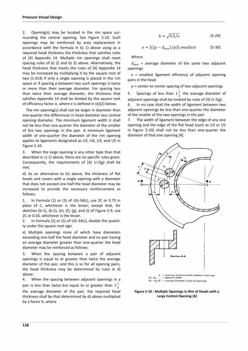
Pressure Vessel Design
128
2. Opening(s) may be located in the rim space sur-rounding the central opening. See Figure 5-10. Such openings may be reinforced by area replacement in accordance with the formula in b) 1) above using as a required head thickness the thickness that satisfies rules of [4] Appendix 14. Multiple rim openings shall meet spacing rules of b) 2) and b) 3) above. Alternatively, the head thickness that meets the rules of [4] Appendix 14 may be increased by multiplying it by the square root of two (1.414) if only a single opening is placed in the rim space or if spacing p between two such openings is twice or more than their average diameter. For spacing less than twice their average diameter, the thickness that satisfies Appendix 14 shall be divided by the square root of efficiency factor e, where e is defined in (e)(2) below.
The rim opening(s) shall not be larger in diameter than one-quarter the differences in head diameter less central opening diameter. The minimum ligament width U shall not be less than one-quarter the diameter of the smaller of the two openings in the pair. A minimum ligament width of one-quarter the diameter of the rim opening applies to ligaments designated as U2, U4, U3, and U5 in Figure 5-10.
3. When the large opening is any other type than that described in c) 1) above, there are no specific rules given. Consequently, the requirements of [4] U-2(g) shall be met.
d) As an alternative to b1 above, the thickness of flat heads and covers with a single opening with a diameter that does not exceed one-half the head diameter may be increased to provide the necessary reinforcement as follows:
1. In Formula (1) or (3) of UG-34(c), use 2C or 0.75 in place of C, whichever is the lesser; except that, for sketches (b-1), (b-2), (e), (f), (g), and (i) of Figure 5-9, use 2C or 0.50, whichever is the lesser. 2. In Formula (2) or (5) of UG-34(c), double the quanti-ty under the square root sign.
e) Multiple openings none of which have diameters exceeding one-half the head diameter and no pair having an average diameter greater than one-quarter the head diameter may be reinforced as follows:
3. When the spacing between a pair of adjacent openings is equal to or greater than twice the average diameter of the pair, and this is so for all opening pairs, the head thickness may be determined by rules in d) above. 4. When the spacing between adjacent openings in a
pair is less than twice but equal to or greater than
the average diameter of the pair, the required head thickness shall be that determined by d) above multiplied by a factor h, where
(5-29)
(5-30)
Where
= average diameter of the same two adjacent openings
= smallest ligament efficiency of adjacent opening pairs in the head
= center-to-center spacing of two adjacent openings
5. Spacings of less than
the average diameter of
adjacent openings shall be treated by rules of [4] U-2(g). 6. In no case shall the width of ligament between two adjacent openings be less than one-quarter the diameter of the smaller of the two openings in the pair. 7. The width of ligament between the edge of any one opening and the edge of the flat head (such as U3 or U5 in Figure 5-10) shall not be less than one-quarter the diameter of that one opening [4].
Figure 5-10 : Multiple Openings in Rim of Heads with a Large Central Opening [4]
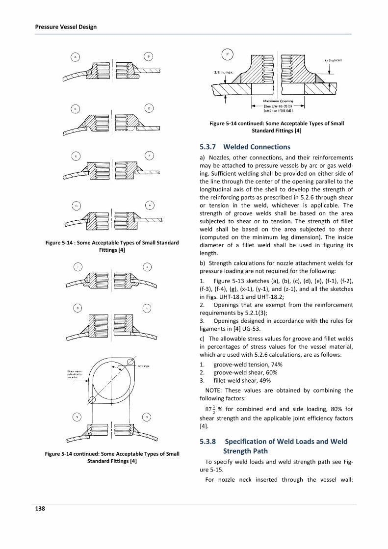
Pressure Vessel Design
138
Figure 5-14 : Some Acceptable Types of Small Standard Fittings [4]
Figure 5-14 continued: Some Acceptable Types of Small Standard Fittings [4]
Figure 5-14 continued: Some Acceptable Types of Small Standard Fittings [4]
5.3.7 Welded Connections
a) Nozzles, other connections, and their reinforcements may be attached to pressure vessels by arc or gas weld-ing. Sufficient welding shall be provided on either side of the line through the center of the opening parallel to the longitudinal axis of the shell to develop the strength of the reinforcing parts as prescribed in 5.2.6 through shear or tension in the weld, whichever is applicable. The strength of groove welds shall be based on the area subjected to shear or to tension. The strength of fillet weld shall be based on the area subjected to shear (computed on the minimum leg dimension). The inside diameter of a fillet weld shall be used in figuring its length.
b) Strength calculations for nozzle attachment welds for pressure loading are not required for the following:
1. Figure 5-13 sketches (a), (b), (c), (d), (e), (f-1), (f-2), (f-3), (f-4), (g), (x-1), (y-1), and (z-1), and all the sketches in Figs. UHT-18.1 and UHT-18.2; 2. Openings that are exempt from the reinforcement requirements by 5.2.1(3); 3. Openings designed in accordance with the rules for ligaments in [4] UG-53.
c) The allowable stress values for groove and fillet welds in percentages of stress values for the vessel material, which are used with 5.2.6 calculations, are as follows:
1. groove-weld tension, 74% 2. groove-weld shear, 60% 3. fillet-weld shear, 49%
NOTE: These values are obtained by combining the following factors:
% for combined end and side loading, 80% for
shear strength and the applicable joint efficiency factors [4].
5.3.8 Specification of Weld Loads and Weld Strength Path
To specify weld loads and weld strength path see Fig-ure 5-15.
For nozzle neck inserted through the vessel wall:
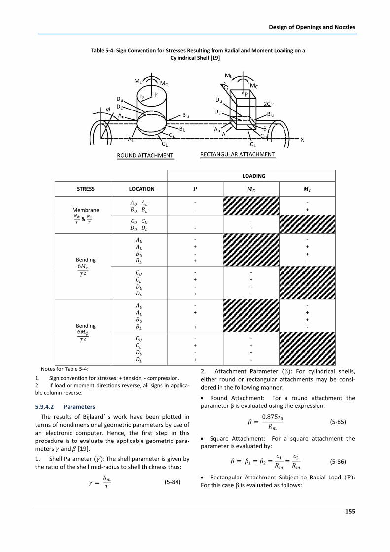
Design of Openings and Nozzles
155
Table 5-4: Sign Convention for Stresses Resulting from Radial and Moment Loading on a Cylindrical Shell [19]
LOADING
STRESS LOCATION
Membrane
&
- -
- +
- -
- +
Bending
- + - +
- + + -
- + - +
- + + -
Bending
- + - +
- + + -
- + - +
- + + -
Notes for Table 5-4:
1. Sign convention for stresses: + tension, - compression. 2. If load or moment directions reverse, all signs in applica-ble column reverse.
5.9.4.2 Parameters
The results of Bijlaard’ s work have been plotted in terms of nondimensional geometric parameters by use of an electronic computer. Hence, the first step in this procedure is to evaluate the applicable geometric para-meters and [19].
1. Shell Parameter : The shell parameter is given by the ratio of the shell mid-radius to shell thickness thus:
(5-84)
2. Attachment Parameter : For cylindrical shells, either round or rectangular attachments may be consi-dered in the following manner:
Round Attachment: For a round attachment the parameter β is evaluated using the expression:
(5-85)
Square Attachment: For a square attachment the parameter is evaluated by:
(5-86)
Rectangular Attachment Subject to Radial Load : For this case is evaluated as follows:
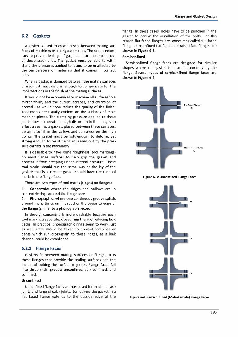
Flange and Gasket Design
195
6.2 Gaskets
A gasket is used to create a seal between mating sur-faces of machines or piping assemblies. The seal is neces-sary to prevent leakage of gas, liquid, or dust into or out of these assemblies. The gasket must be able to with-stand the pressures applied to it and to be unaffected by the temperature or materials that it comes in contact with.
When a gasket is clamped between the mating surfaces of a joint it must deform enough to compensate for the imperfections in the finish of the mating surfaces.
It would not be economical to machine all surfaces to a mirror finish, and the bumps, scrapes, and corrosion of normal use would soon reduce the quality of the finish. Tool marks are usually evident on the surfaces of most machine pieces. The clamping pressure applied to these joints does not create enough distortion in the flanges to effect a seal, so a gasket, placed between these surfaces, deforms to fill in the valleys and compress on the high points. The gasket must be soft enough to deform, yet strong enough to resist being squeezed out by the pres-sure carried in the machinery.
It is desirable to have some roughness (tool markings) on most flange surfaces to help grip the gasket and prevent it from creeping under internal pressure. These tool marks should run the same way as the lay of the gasket; that is, a circular gasket should have circular tool marks in the flange face.
There are two types of tool marks (ridges) on flanges:
1. Concentric: where the ridges and hollows are in concentric rings around the flange face. 2. Phonographic: where one continuous groove spirals around many times until it reaches the opposite edge of the flange (similar to a phonograph record).
In theory, concentric is more desirable because each tool mark is a separate, closed ring thereby reducing leak paths. In practice, phonographic rings seem to work just as well. Care should be taken to prevent scratches or dents which run cross-grain to these ridges, as a leak channel could be established.
6.2.1 Flange Faces
Gaskets fit between mating surfaces or flanges. It is these flanges that provide the sealing surfaces and the means of bolting the surface together. Flange faces fall into three main groups: unconfined, semiconfined, and confined.
Unconfined
Unconfined flange faces as those used for machine case joints and large circular joints. Sometimes the gasket in a flat faced flange extends to the outside edge of the
flange. In these cases, holes have to be punched in the gasket to permit the installation of the bolts. For this reason flat faced flanges are sometimes called full faced flanges. Unconfined flat faced and raised face flanges are shown in Figure 6-3.
Semiconfined
Semiconfined flange faces are designed for circular shapes where the gasket is located accurately by the flange. Several types of semiconfined flange faces are shown in Figure 6-4.
Figure 6-3: Unconfined Flange Faces
Figure 6-4: Semiconfined (Male-Female) Flange Faces
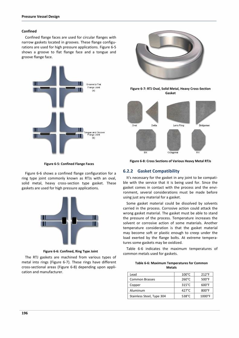
Pressure Vessel Design
196
Confined
Confined flange faces are used for circular flanges with narrow gaskets located in grooves. These flange configu-rations are used for high pressure applications. Figure 6-5 shows a groove to flat flange face and a tongue and groove flange face.
Figure 6-5: Confined Flange Faces
Figure 6-6 shows a confined flange configuration for a ring type joint commonly known as RTJs with an oval, solid metal, heavy cross-section type gasket. These gaskets are used for high pressure applications.
Figure 6-6: Confined, Ring Type Joint
The RTJ gaskets are machined from various types of metal into rings (Figure 6-7). These rings have different cross-sectional areas (Figure 6-8) depending upon appli-cation and manufacturer.
Figure 6-7: RTJ Oval, Solid Metal, Heavy Cross-Section Gasket
Figure 6-8: Cross Sections of Various Heavy Metal RTJs
6.2.2 Gasket Compatibility
It's necessary for the gasket in any joint to be compati-ble with the service that it is being used for. Since the gasket comes in contact with the process and the envi-ronment, several considerations must be made before using just any material for a gasket.
Some gasket material could be dissolved by solvents carried in the process. Corrosive action could attack the wrong gasket material. The gasket must be able to stand the pressure of the process. Temperature increases the solvent or corrosive action of some materials. Another temperature consideration is that the gasket material may become soft or plastic enough to creep under the load exerted by the flange bolts. At extreme tempera-tures some gaskets may be oxidized.
Table 6-6 indicates the maximum temperatures of common metals used for gaskets.
Table 6-6: Maximum Temperatures for Common Metals
Lead 100°C 212°F
Common Brasses 260°C 500°F
Copper 315°C 600°F
Aluminum 427°C 800°F
Stainless Steel, Type 304 538°C 1000°F
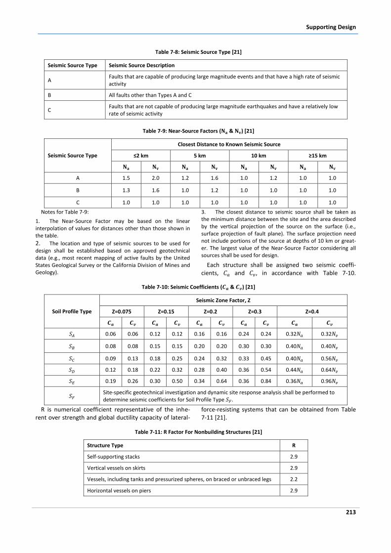
Supporting Design
213
Table 7-8: Seismic Source Type [21]
Seismic Source Type Seismic Source Description
A Faults that are capable of producing large magnitude events and that have a high rate of seismic activity
B All faults other than Types A and C
C Faults that are not capable of producing large magnitude earthquakes and have a relatively low rate of seismic activity
Table 7-9: Near-Source Factors ( & ) [21]
Seismic Source Type
Closest Distance to Known Seismic Source
≤2 km 5 km 10 km ≥15 km
A 1.5 2.0 1.2 1.6 1.0 1.2 1.0 1.0
B 1.3 1.6 1.0 1.2 1.0 1.0 1.0 1.0
C 1.0 1.0 1.0 1.0 1.0 1.0 1.0 1.0
Notes for Table 7-9:
1. The Near-Source Factor may be based on the linear interpolation of values for distances other than those shown in the table.
2. The location and type of seismic sources to be used for design shall be established based on approved geotechnical data (e.g., most recent mapping of active faults by the United States Geological Survey or the California Division of Mines and Geology).
3. The closest distance to seismic source shall be taken as the minimum distance between the site and the area described by the vertical projection of the source on the surface (i.e., surface projection of fault plane). The surface projection need not include portions of the source at depths of 10 km or great-er. The largest value of the Near-Source Factor considering all sources shall be used for design.
Each structure shall be assigned two seismic coeffi-cients, and , in accordance with Table 7-10.
Table 7-10: Seismic Coefficients ( & ) [21]
Soil Profile Type
Seismic Zone Factor, Z
Z=0.075 Z=0.15 Z=0.2 Z=0.3 Z=0.4
0.06 0.06 0.12 0.12 0.16 0.16 0.24 0.24 0.32 0.32
0.08 0.08 0.15 0.15 0.20 0.20 0.30 0.30 0.40 0.40
0.09 0.13 0.18 0.25 0.24 0.32 0.33 0.45 0.40 0.56
0.12 0.18 0.22 0.32 0.28 0.40 0.36 0.54 0.44 0.64
0.19 0.26 0.30 0.50 0.34 0.64 0.36 0.84 0.36 0.96
Site-specific geotechnical investigation and dynamic site response analysis shall be performed to determine seismic coefficients for Soil Profile Type .
R is numerical coefficient representative of the inhe-rent over strength and global ductility capacity of lateral-
force-resisting systems that can be obtained from Table 7-11 [21].
Table 7-11: R Factor For Nonbuilding Structures [21]
Structure Type R
Self-supporting stacks 2.9
Vertical vessels on skirts 2.9
Vessels, including tanks and pressurized spheres, on braced or unbraced legs 2.2
Horizontal vessels on piers 2.9
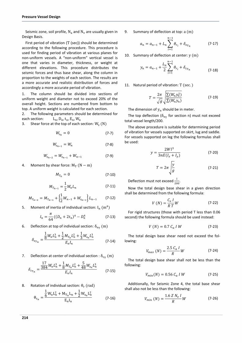
Pressure Vessel Design
214
Seismic zone, soil profile, and are usually given in Design Basis.
First period of vibration ( (sec)) should be determined according to the following procedure. This procedure is used for finding period of vibration at various planes for non-uniform vessels. A “non-uniform” vertical vessel is one that varies in diameter, thickness, or weight at different elevations. This procedure distributes the seismic forces and thus base shear, along the column in proportion to the weights of each section. The results are a more accurate and realistic distribution of forces and accordingly a more accurate period of vibration.
1. The column should be divided into sections of uniform weight and diameter not to exceed 20% of the overall height. Sections are numbered from bottom to top. A uniform weight is calculated for each section. 2. The following parameters should be determined for each section: 3. Shear force at the top of each section:
(7-7)
(7-8)
(7-9)
4. Moment by shear force:
(7-10)
(7-11)
(7-12)
5. Moment of inertia of individual section:
(7-13)
6. Deflection at top of individual section:
(7-14)
7. Deflection at center of individual section :
(7-15)
8. Rotation of individual section:
(7-16)
9. Summary of deflection at top:
(7-17)
10. Summary of deflection at center:
(7-18)
11. Natural period of vibration:
(7-19)
The dimension of should be in meter.
The top deflection ( for section n) must not exceed
total vessel length/200.
The above procedure is suitable for determining period of vibration for vessels supported on skirt, lug and saddle. For vessels supported on leg the following formulas shall be used:
(7-20)
(7-21)
Deflection must not exceed
.
Now the total design base shear in a given direction shall be determined from the following formula:
(7-22)
For rigid structures (those with period T less than 0.06 second) the following formula should be used instead:
(7-23)
The total design base shear need not exceed the fol-lowing:
(7-24)
The total design base shear shall not be less than the following:
(7-25)
Additionally, for Seismic Zone 4, the total base shear shall also not be less than the following:
(7-26)
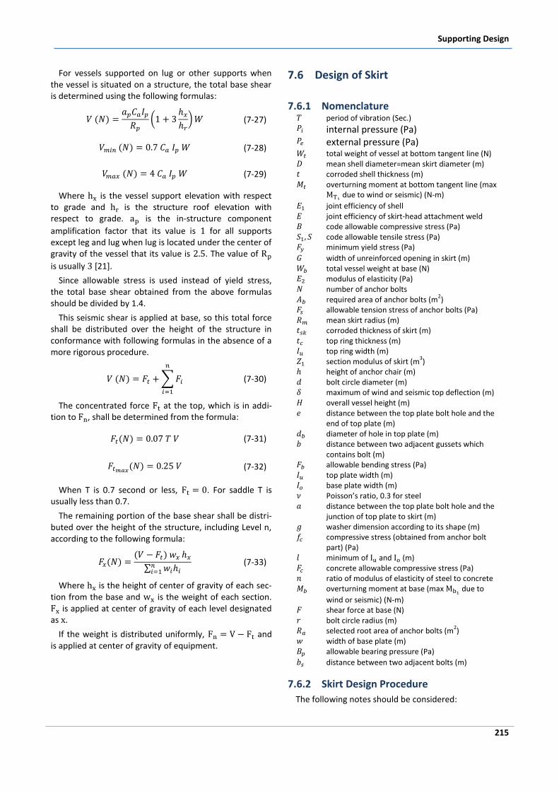
Supporting Design
215
For vessels supported on lug or other supports when the vessel is situated on a structure, the total base shear is determined using the following formulas:
(7-27)
(7-28)
(7-29)
Where is the vessel support elevation with respect to grade and is the structure roof elevation with respect to grade. is the in-structure component
amplification factor that its value is for all supports except leg and lug when lug is located under the center of gravity of the vessel that its value is . The value of
is usually [21].
Since allowable stress is used instead of yield stress, the total base shear obtained from the above formulas should be divided by 1.4.
This seismic shear is applied at base, so this total force shall be distributed over the height of the structure in conformance with following formulas in the absence of a more rigorous procedure.
(7-30)
The concentrated force at the top, which is in addi-tion to , shall be determined from the formula:
(7-31)
(7-32)
When T is 0.7 second or less, . For saddle T is usually less than 0.7.
The remaining portion of the base shear shall be distri-buted over the height of the structure, including Level n, according to the following formula:
(7-33)
Where is the height of center of gravity of each sec-tion from the base and is the weight of each section. is applied at center of gravity of each level designated as .
If the weight is distributed uniformly, and is applied at center of gravity of equipment.
7.6 Design of Skirt
7.6.1 Nomenclature period of vibration (Sec.) internal pressure (Pa) external pressure (Pa) total weight of vessel at bottom tangent line (N) mean shell diameter=mean skirt diameter (m) corroded shell thickness (m) overturning moment at bottom tangent line (max
due to wind or seismic) (N-m)
joint efficiency of shell joint efficiency of skirt-head attachment weld code allowable compressive stress (Pa) code allowable tensile stress (Pa) minimum yield stress (Pa)
width of unreinforced opening in skirt (m) total vessel weight at base (N) modulus of elasticity (Pa) number of anchor bolts required area of anchor bolts (m
2)
allowable tension stress of anchor bolts (Pa) mean skirt radius (m) corroded thickness of skirt (m) top ring thickness (m) top ring width (m) section modulus of skirt (m
3)
height of anchor chair (m) bolt circle diameter (m) maximum of wind and seismic top deflection (m) overall vessel height (m) distance between the top plate bolt hole and the
end of top plate (m) diameter of hole in top plate (m) distance between two adjacent gussets which
contains bolt (m) allowable bending stress (Pa) top plate width (m) base plate width (m) Poisson’s ratio, 0.3 for steel distance between the top plate bolt hole and the
junction of top plate to skirt (m) washer dimension according to its shape (m) compressive stress (obtained from anchor bolt
part) (Pa) minimum of and (m) concrete allowable compressive stress (Pa) ratio of modulus of elasticity of steel to concrete overturning moment at base (max
due to
wind or seismic) (N-m) shear force at base (N) bolt circle radius (m) selected root area of anchor bolts (m
2)
width of base plate (m) allowable bearing pressure (Pa)
distance between two adjacent bolts (m)
7.6.2 Skirt Design Procedure
The following notes should be considered:
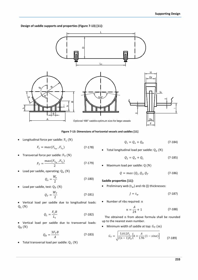
Supporting Design
233
Design of saddle supports and properties (Figure 7-13) [11]:
Figure 7-13: Dimensions of horizontal vessels and saddles [11]
Longitudinal force per saddle:
(7-178)
Transversal force per saddle:
(7-179)
Load per saddle, operating:
(7-180)
Load per saddle, test:
(7-181)
Vertical load per saddle due to longitudinal loads:
(7-182)
Vertical load per saddle due to transversal loads:
(7-183)
Total transversal load per saddle:
(7-184)
Total longitudinal load per saddle:
(7-185)
Maximum load per saddle:
(7-186)
Saddle properties [11]:
Preliminary web ( ) and rib ( ) thicknesses:
(7-187)
Number of ribs required:
(7-188)
The obtained from above formula shall be rounded up to the nearest even number.
Minimum width of saddle at top:
(7-189)
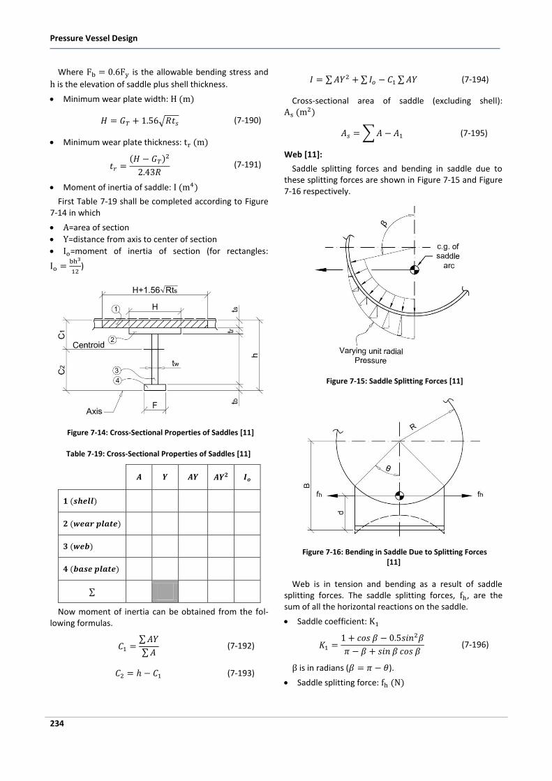
Pressure Vessel Design
234
Where is the allowable bending stress and
is the elevation of saddle plus shell thickness.
Minimum wear plate width:
(7-190)
Minimum wear plate thickness:
(7-191)
Moment of inertia of saddle:
First Table 7-19 shall be completed according to Figure 7-14 in which
=area of section
=distance from axis to center of section
=moment of inertia of section (for rectangles:
)
Figure 7-14: Cross-Sectional Properties of Saddles [11]
Table 7-19: Cross-Sectional Properties of Saddles [11]
Now moment of inertia can be obtained from the fol-lowing formulas.
(7-192)
(7-193)
(7-194)
Cross-sectional area of saddle (excluding shell):
(7-195)
Web [11]:
Saddle splitting forces and bending in saddle due to these splitting forces are shown in Figure 7-15 and Figure 7-16 respectively.
Figure 7-15: Saddle Splitting Forces [11]
Figure 7-16: Bending in Saddle Due to Splitting Forces [11]
Web is in tension and bending as a result of saddle splitting forces. The saddle splitting forces, , are the sum of all the horizontal reactions on the saddle.
Saddle coefficient:
(7-196)
is in radians ( ).
Saddle splitting force:
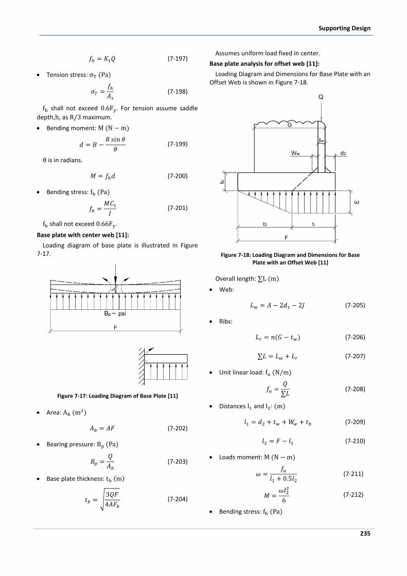
Supporting Design
235
(7-197)
Tension stress:
(7-198)
shall not exceed . For tension assume saddle
depth, , as maximum.
Bending moment:
(7-199)
is in radians.
(7-200)
Bending stress:
(7-201)
shall not exceed .
Base plate with center web [11]:
Loading diagram of base plate is illustrated in Figure 7-17.
Figure 7-17: Loading Diagram of Base Plate [11]
Area:
(7-202)
Bearing pressure:
(7-203)
Base plate thickness:
(7-204)
Assumes uniform load fixed in center.
Base plate analysis for offset web [11]:
Loading Diagram and Dimensions for Base Plate with an Offset Web is shown in Figure 7-18.
Figure 7-18: Loading Diagram and Dimensions for Base Plate with an Offset Web [11]
Overall length:
Web:
(7-205)
Ribs:
(7-206)
(7-207)
Unit linear load:
(7-208)
Distances and :
(7-209)
(7-210)
Loads moment:
(7-211)
(7-212)
Bending stress:
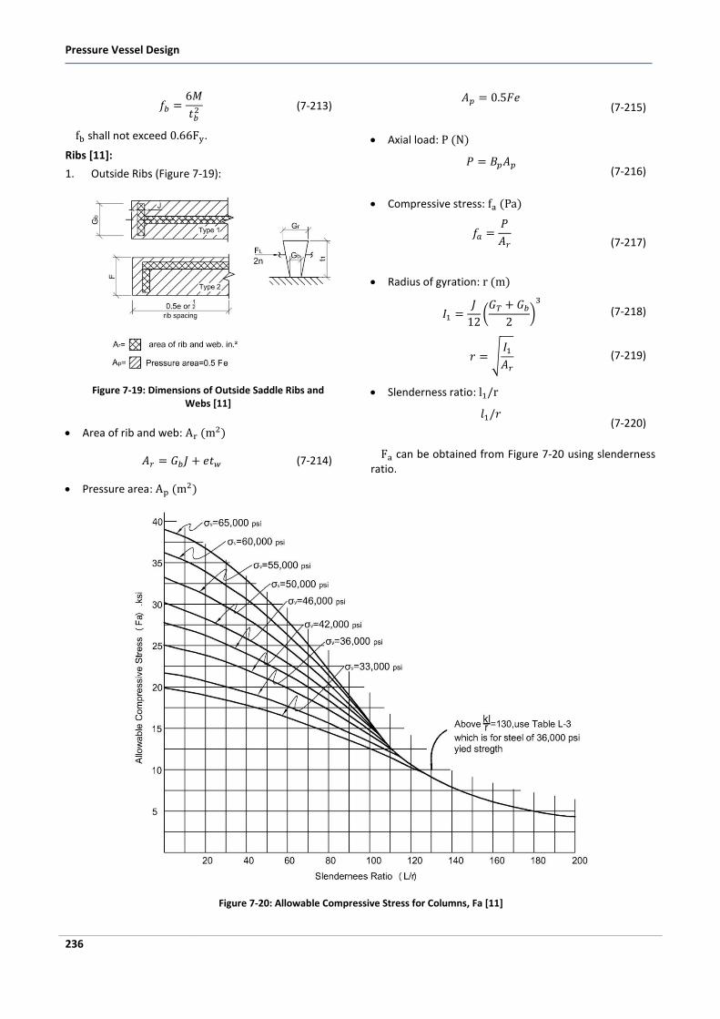
Pressure Vessel Design
236
(7-213)
shall not exceed .
Ribs [11]:
1. Outside Ribs (Figure 7-19):
Figure 7-19: Dimensions of Outside Saddle Ribs and Webs [11]
Area of rib and web:
(7-214)
Pressure area:
(7-215)
Axial load:
(7-216)
Compressive stress:
(7-217)
Radius of gyration:
(7-218)
(7-219)
Slenderness ratio:
(7-220)
can be obtained from Figure 7-20 using slenderness ratio.
Figure 7-20: Allowable Compressive Stress for Columns, Fa [11]
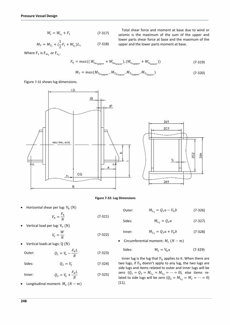
Pressure Vessel Design
248
(7-317)
(7-318)
Where is or .
Total shear force and moment at base due to wind or seismic is the maximum of the sum of the upper and lower parts shear force at base and the maximum of the upper and the lower parts moment at base.
(7-319)
(7-320)
Figure 7-32 shows lug dimensions.
Figure 7-32: Lug Dimensions
Horizontal shear per lug:
(7-321)
Vertical load per lug:
(7-322)
Vertical loads at lugs:
Outer:
(7-323)
Sides: (7-324)
Inner:
(7-325)
Longitudinal moment:
Outer: (7-326)
Sides: (7-327)
Inner: (7-328)
Circumferential moment:
Sides: (7-329)
Inner lug is the lug that applies to it. When there are two lugs, if doesn’t apply to any lug, the two lugs are side lugs and items related to outer and inner lugs will be zero (
), else items re-
lated to side lugs will be zero ( )
[11].
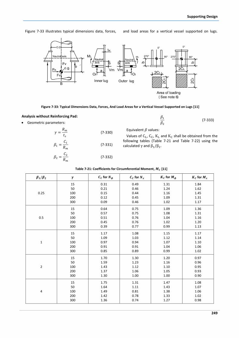
Supporting Design
249
Figure 7-33 illustrates typical dimensions data, forces, and load areas for a vertical vessel supported on lugs.
Figure 7-33: Typical Dimensions Data, Forces, And Load Areas for a Vertical Vessel Supported on Lugs [11]
Analysis without Reinforcing Pad:
Geometric parameters:
(7-330)
(7-331)
(7-332)
(7-333)
Equivalent values:
Values of , , and shall be obtained from the following tables (Table 7-21 and Table 7-22) using the calculated and .
Table 7-21: Coefficients for Circumferential Moment, [11]
for for for for
0.25
15 50
100 200 300
0.31 0.21 0.15 0.12 0.09
0.49 0.46 0.44 0.45 0.46
1.31 1.24 1.16 1.09 1.02
1.84 1.62 1.45 1.31 1.17
0.5
15 50
100 200 300
0.64 0.57 0.51 0.45 0.39
0.75 0.75 0.76 0.76 0.77
1.09 1.08 1.04 1.02 0.99
1.36 1.31 1.16 1.20 1.13
1
15 50
100 200 300
1.17 1.09 0.97 0.91 0.85
1.08 1.03 0.94 0.91 0.89
1.15 1.12 1.07 1.04 0.99
1.17 1.14 1.10 1.06 1.02
2
15 50
100 200 300
1.70 1.59 1.43 1.37 1.30
1.30 1.23 1.12 1.06 1.00
1.20 1.16 1.10 1.05 1.00
0.97 0.96 0.95 0.93 0.90
4
15 50
100 200 300
1.75 1.64 1.49 1.42 1.36
1.31 1.11 0.81 0.78 0.74
1.47 1.43 1.38 1.33 1.27
1.08 1.07 1.06 1.02 0.98
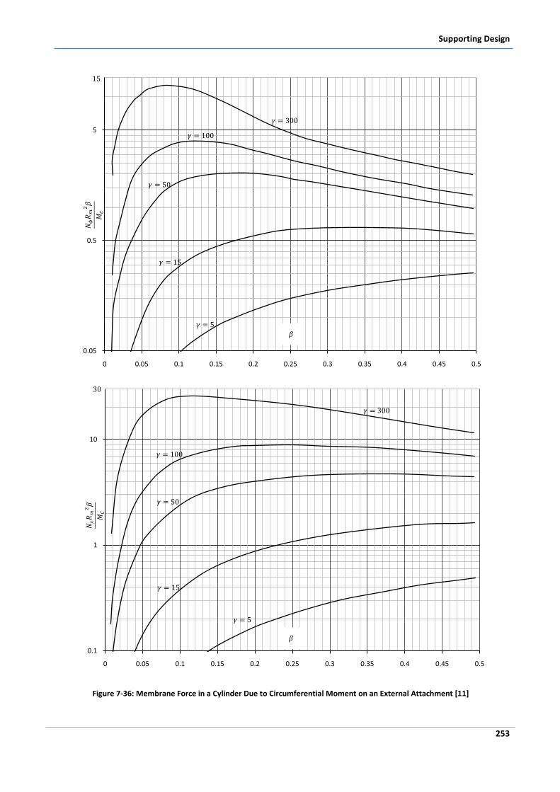
Supporting Design
253
Figure 7-36: Membrane Force in a Cylinder Due to Circumferential Moment on an External Attachment [11]
0.05
0.5
5
0 0.05 0.1 0.15 0.2 0.25 0.3 0.35 0.4 0.45 0.5
0.1
1
10
0 0.05 0.1 0.15 0.2 0.25 0.3 0.35 0.4 0.45 0.5
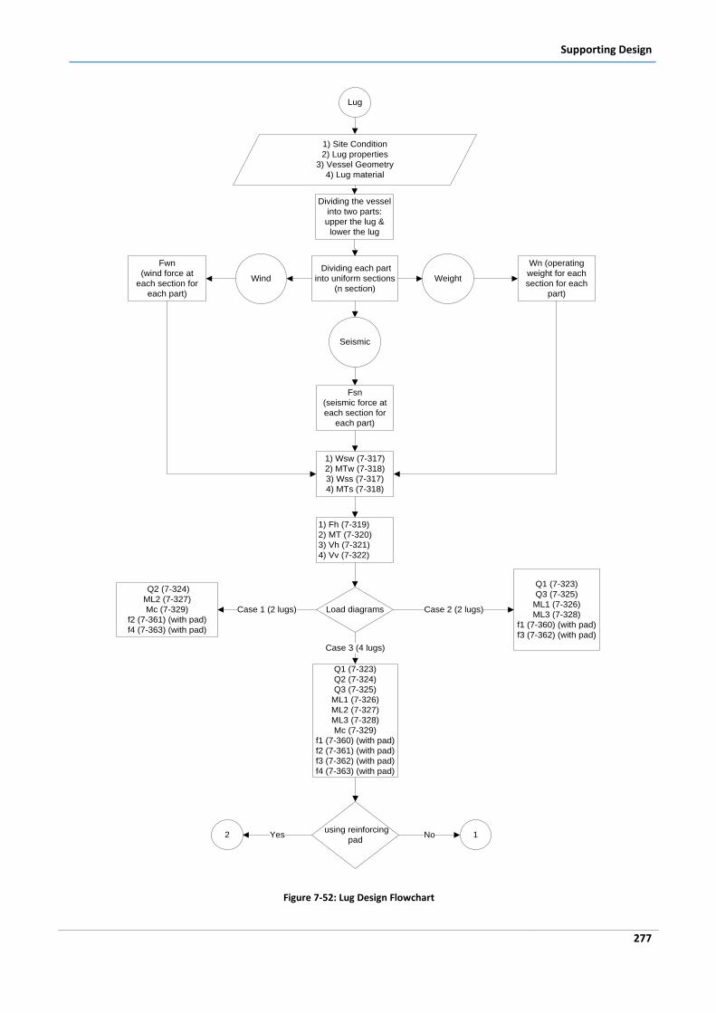
Supporting Design
277
Lug
1) Site Condition
2) Lug properties
3) Vessel Geometry
4) Lug material
Dividing each part
into uniform sections
(n section)
Weight
Wn (operating
weight for each
section for each
part)
Wind
Fwn
(wind force at
each section for
each part)
Seismic
Fsn
(seismic force at
each section for
each part)
1) Wsw (7-317)
2) MTw (7-318)
3) Wss (7-317)
4) MTs (7-318)
Dividing the vessel
into two parts:
upper the lug &
lower the lug
1) Fh (7-319)
2) MT (7-320)
3) Vh (7-321)
4) Vv (7-322)
Load diagrams
Q2 (7-324)
ML2 (7-327)
Mc (7-329)
f2 (7-361) (with pad)
f4 (7-363) (with pad)
Case 1 (2 lugs)
Q1 (7-323)
Q3 (7-325)
ML1 (7-326)
ML3 (7-328)
f1 (7-360) (with pad)
f3 (7-362) (with pad)
Case 2 (2 lugs)
Q1 (7-323)
Q2 (7-324)
Q3 (7-325)
ML1 (7-326)
ML2 (7-327)
ML3 (7-328)
Mc (7-329)
f1 (7-360) (with pad)
f2 (7-361) (with pad)
f3 (7-362) (with pad)
f4 (7-363) (with pad)
Case 3 (4 lugs)
using reinforcing
pad2 Yes 1No
Figure 7-52: Lug Design Flowchart
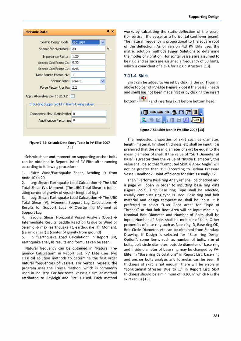
Supporting Design
281
Figure 7-55: Seismic Data Entry Table in PV-Elite 2007 [13]
Seismic shear and moment on supporting anchor bolts can be obtained in Report List of PV-Elite after running according to following procedure:
1. Skirt: Wind/Earthquake Shear, Bending → from node 10 to 20 2. Leg: Shear: Earthquake Load Calculation → The UBC Total Shear (V), Moment: (The UBC Total Shear) x (oper-ating center of gravity of vessel+ length of leg) 3. Lug: Shear: Earthquake Load Calculation → The UBC Total Shear (V), Moment: Support Lug Calculations → Results for Support Lugs → Overturning Moment at Support Lug 4. Saddle: Shear: Horizontal Vessel Analysis (Ope.) → Intermediate Results: Saddle Reaction Q due to Wind or Seismic → max (earthquake Ft, earthquake Fl), Moment: (seismic shear) x (center of gravity from ground) 5. In “Earthquake Load Calculation” in Report List, earthquake analysis results and formulas can be seen.
Natural frequency can be obtained in “Natural Fre-quency Calculation” in Report List. PV Elite uses two classical solution methods to determine the first order natural frequencies of vessels. For vertical vessels, the program uses the Freese method, which is commonly used in industry. For horizontal vessels a similar method attributed to Rayleigh and Ritz is used. Each method
works by calculating the static deflection of the vessel (for vertical, the vessel as a horizontal cantilever beam). The natural frequency is proportional to the square root of the deflection. As of version 4.3 PV Elite uses the matrix solution methods (Eigen Solution) to determine the modes of vibration. Horizontal vessels are assumed to be rigid and as such are assigned a frequency of 33 hertz, which is coincident of a ZPA for a rigid structure [13].
7.11.4 Skirt
Skirt can be added to vessel by clicking the skirt icon in above toolbar of PV-Elite (Figure 7-56) if the vessel (heads and shell) has not been made first or by clicking the insert
bottom ( ) and inserting skirt before bottom head.
Figure 7-56: Skirt Icon in PV-Elite 2007 [13]
The requested properties of skirt such as diameter, length, material, finished thickness, etc shall be input. It is preferred that the mean diameter of skirt be equal to the mean diameter of shell. If the value of “Skirt Diameter at Base” is greater than the value of “Inside Diameter”, this value shall be so that “Computed Skirt ½ Apex Angle” will not be greater than 15° (according to Bednar Pressure Vessel Handbook). Joint efficiency for skirt is usually 0.7.
Then “Perform Base ring Analysis” shall be checked and a page will open in order to inputting base ring data (Figure 7-57). First Base ring Type shall be selected, usually continues ring type is used. Base ring and bolt material and design temperature shall be input. It is preferred to select “User Root Area” for “Type of Threads” so that Bolt Root Area will be input manually. Nominal Bolt Diameter and Number of Bolts shall be input, Number of Bolts shall be multiple of four. Other properties of base ring such as Base ring ID, Base ring OD, Bolt Circle Diameter, etc can be obtained from Standard Drawing. If Design is selected for “Base ring Design Option”, some items such as number of bolts, size of bolts, bolt circle diameter, outside diameter of base ring and inside diameter of base ring may be changed by PV-Elite. In “Base ring Calculations” in Report List, base ring and anchor bolts analysis and formulas can be seen. If thickness of skirt is not enough, there will be errors in “Longitudinal Stresses Due to …” in Report List. Skirt thickness should be a minimum of R/200 in which R is the skirt radius [13].
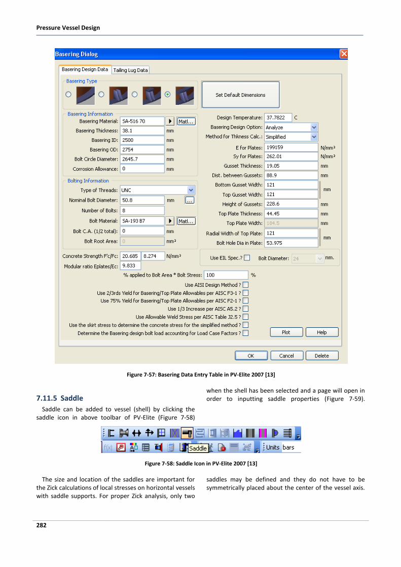
Pressure Vessel Design
282
Figure 7-57: Basering Data Entry Table in PV-Elite 2007 [13]
7.11.5 Saddle
Saddle can be added to vessel (shell) by clicking the saddle icon in above toolbar of PV-Elite (Figure 7-58)
when the shell has been selected and a page will open in order to inputting saddle properties (Figure 7-59).
Figure 7-58: Saddle Icon in PV-Elite 2007 [13]
The size and location of the saddles are important for the Zick calculations of local stresses on horizontal vessels with saddle supports. For proper Zick analysis, only two
saddles may be defined and they do not have to be symmetrically placed about the center of the vessel axis.
Welding
297
8 Welding
8.1 Introduction
Today welding is the most commonly used method in fabrication of pressure vessel parts and defined as a process of permanent joining two materials (usually metals) through localized union by using a suitable combination of temperature, pressure and metallurgical conditions. Depending upon the combination of tempera-ture and pressure from a high temperature with no pressure to a high pressure with low temperature, a wide range of welding methods has been developed [22].
Therefore, there are three welding methods [10]:
Forge welding: As the oldest method, it is applicable to low-carbon steel. It is performed by heating two pieces of metal to a high temperature and then hammering them together. The joint is not particularly strong.
Fusion welding: This process does not require any pressure to form the weld. The seam to be welded is heated, usually by burning gas or an electric arc to fusion temperature and additional metal, if required, is applied by melting a filler rod of suitable composition.
Pressure welding: It is used in processes such as resis-tance welding, which utilized the heat created by an electric current passing against high resistance through the two pieces at the contact interface.
The most widely used industrial welding method is arc welding, which is any of several fusion welding processes wherein the heat of fusion is generated by an electric arc [10].
In order to know the welding processes, it is important to know the different types of common joints and welds.
8.2 Terms and Definitions of Welds
8.2.1 General Terms
There are some general terms and definitions in weld-ing as follows:
Joint: A Configuration of Members (To be welded).
Types of Joints: Butt Joint, Lap Joint, T Joint, open cor-ner joint, closed corner joint.
Weld: A Union of Materials Caused by Heat and/or Pressure (The Process of Welding).
Types of Welds: Butt Weld, Fillet Weld, Tack Weld, Spot/Seam Weld, Plug/Slot Weld, Edge Weld
Weld Preparation: Preparing a joint to allow access and fusion through the joint faces.
Types of Preparation: Bevel’s, V’s, J’s, U’s, single and double sided.
8.2.2 Types of common joints
The most commonly used welded joints are shown below [23]:
The welded Butt joint, as shown in Figure 8-1, is a joint in which two or more parts are joined end to end or edge to edge.
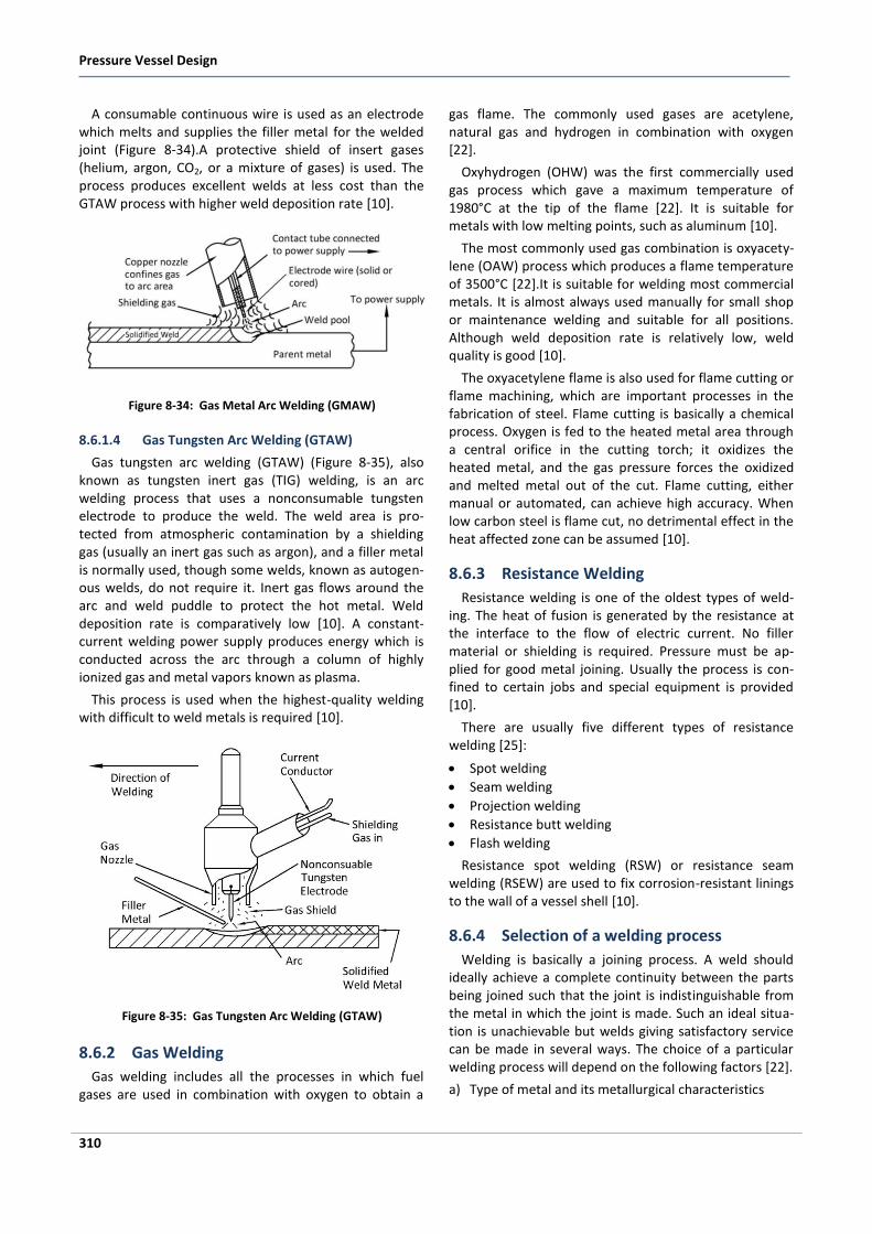
Pressure Vessel Design
310
A consumable continuous wire is used as an electrode which melts and supplies the filler metal for the welded joint (Figure 8-34).A protective shield of insert gases (helium, argon, CO2, or a mixture of gases) is used. The process produces excellent welds at less cost than the GTAW process with higher weld deposition rate [10].
Figure 8-34: Gas Metal Arc Welding (GMAW)
8.6.1.4 Gas Tungsten Arc Welding (GTAW)
Gas tungsten arc welding (GTAW) (Figure 8-35), also known as tungsten inert gas (TIG) welding, is an arc welding process that uses a nonconsumable tungsten electrode to produce the weld. The weld area is pro-tected from atmospheric contamination by a shielding gas (usually an inert gas such as argon), and a filler metal is normally used, though some welds, known as autogen-ous welds, do not require it. Inert gas flows around the arc and weld puddle to protect the hot metal. Weld deposition rate is comparatively low [10]. A constant-current welding power supply produces energy which is conducted across the arc through a column of highly ionized gas and metal vapors known as plasma.
This process is used when the highest-quality welding with difficult to weld metals is required [10].
Figure 8-35: Gas Tungsten Arc Welding (GTAW)
8.6.2 Gas Welding
Gas welding includes all the processes in which fuel gases are used in combination with oxygen to obtain a
gas flame. The commonly used gases are acetylene, natural gas and hydrogen in combination with oxygen [22].
Oxyhydrogen (OHW) was the first commercially used gas process which gave a maximum temperature of 1980°C at the tip of the flame [22]. It is suitable for metals with low melting points, such as aluminum [10].
The most commonly used gas combination is oxyacety-lene (OAW) process which produces a flame temperature of 3500°C [22].It is suitable for welding most commercial metals. It is almost always used manually for small shop or maintenance welding and suitable for all positions. Although weld deposition rate is relatively low, weld quality is good [10].
The oxyacetylene flame is also used for flame cutting or flame machining, which are important processes in the fabrication of steel. Flame cutting is basically a chemical process. Oxygen is fed to the heated metal area through a central orifice in the cutting torch; it oxidizes the heated metal, and the gas pressure forces the oxidized and melted metal out of the cut. Flame cutting, either manual or automated, can achieve high accuracy. When low carbon steel is flame cut, no detrimental effect in the heat affected zone can be assumed [10].
8.6.3 Resistance Welding
Resistance welding is one of the oldest types of weld-ing. The heat of fusion is generated by the resistance at the interface to the flow of electric current. No filler material or shielding is required. Pressure must be ap-plied for good metal joining. Usually the process is con-fined to certain jobs and special equipment is provided [10].
There are usually five different types of resistance welding [25]:
Spot welding
Seam welding
Projection welding
Resistance butt welding
Flash welding
Resistance spot welding (RSW) or resistance seam welding (RSEW) are used to fix corrosion-resistant linings to the wall of a vessel shell [10].
8.6.4 Selection of a welding process
Welding is basically a joining process. A weld should ideally achieve a complete continuity between the parts being joined such that the joint is indistinguishable from the metal in which the joint is made. Such an ideal situa-tion is unachievable but welds giving satisfactory service can be made in several ways. The choice of a particular welding process will depend on the following factors [22].
a) Type of metal and its metallurgical characteristics
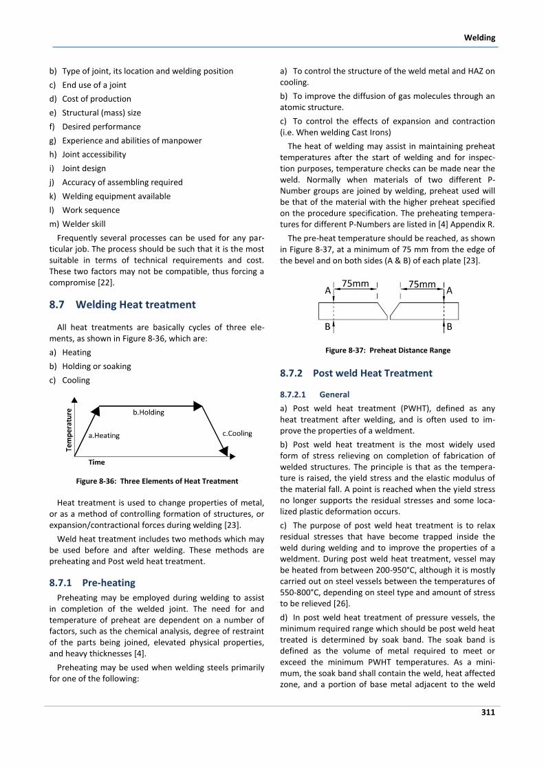
Welding
311
b) Type of joint, its location and welding position
c) End use of a joint
d) Cost of production
e) Structural (mass) size
f) Desired performance
g) Experience and abilities of manpower
h) Joint accessibility
i) Joint design
j) Accuracy of assembling required
k) Welding equipment available
l) Work sequence
m) Welder skill
Frequently several processes can be used for any par-ticular job. The process should be such that it is the most suitable in terms of technical requirements and cost. These two factors may not be compatible, thus forcing a compromise [22].
8.7 Welding Heat treatment
All heat treatments are basically cycles of three ele-ments, as shown in Figure 8-36, which are:
a) Heating
b) Holding or soaking
c) Cooling
Figure 8-36: Three Elements of Heat Treatment
Heat treatment is used to change properties of metal, or as a method of controlling formation of structures, or expansion/contractional forces during welding [23].
Weld heat treatment includes two methods which may be used before and after welding. These methods are preheating and Post weld heat treatment.
8.7.1 Pre-heating
Preheating may be employed during welding to assist in completion of the welded joint. The need for and temperature of preheat are dependent on a number of factors, such as the chemical analysis, degree of restraint of the parts being joined, elevated physical properties, and heavy thicknesses [4].
Preheating may be used when welding steels primarily for one of the following:
a) To control the structure of the weld metal and HAZ on cooling.
b) To improve the diffusion of gas molecules through an atomic structure.
c) To control the effects of expansion and contraction (i.e. When welding Cast Irons)
The heat of welding may assist in maintaining preheat temperatures after the start of welding and for inspec-tion purposes, temperature checks can be made near the weld. Normally when materials of two different P-Number groups are joined by welding, preheat used will be that of the material with the higher preheat specified on the procedure specification. The preheating tempera-tures for different P-Numbers are listed in [4] Appendix R.
The pre-heat temperature should be reached, as shown in Figure 8-37, at a minimum of 75 mm from the edge of the bevel and on both sides (A & B) of each plate [23].
Figure 8-37: Preheat Distance Range
8.7.2 Post weld Heat Treatment
8.7.2.1 General
a) Post weld heat treatment (PWHT), defined as any heat treatment after welding, and is often used to im-prove the properties of a weldment.
b) Post weld heat treatment is the most widely used form of stress relieving on completion of fabrication of welded structures. The principle is that as the tempera-ture is raised, the yield stress and the elastic modulus of the material fall. A point is reached when the yield stress no longer supports the residual stresses and some loca-lized plastic deformation occurs.
c) The purpose of post weld heat treatment is to relax residual stresses that have become trapped inside the weld during welding and to improve the properties of a weldment. During post weld heat treatment, vessel may be heated from between 200-950°C, although it is mostly carried out on steel vessels between the temperatures of 550-800°C, depending on steel type and amount of stress to be relieved [26].
d) In post weld heat treatment of pressure vessels, the minimum required range which should be post weld heat treated is determined by soak band. The soak band is defined as the volume of metal required to meet or exceed the minimum PWHT temperatures. As a mini-mum, the soak band shall contain the weld, heat affected zone, and a portion of base metal adjacent to the weld
Examination and Test
315
9 Examination and Test
9.1 Nondestructive Testing
Nondestructive testing (NDT) is a term used to desig-nate those inspection methods that allow materials to be examined without changing or destroying their useful-ness.
Nondestructive tests are used on weldment for the following reasons [31]:
Improved product reliability
Accident prevention by eliminating faulty products
Determination of acceptability in accordance with a code or specification
Information for repair decisions
Reduction of costs by eliminating further processing of unacceptable components
There are many methods of NDT some of which require a very high level of skill both in application and analysis and therefore NDT operators for these methods require a high degree of training and experience to apply them successfully [23].
The five principle methods of NDT used are:
Visual testing (VT)
Penetrant testing (PT)
Magnetic particle testing (MT)
Ultrasonic testing (UT)
Radiographic testing (RT)
In any type on NDT, two aspects are important:
a) The witnessing of the test as and when needed
b) Review of reports and records of the test
For most commonly used NDT methods except RT, testing is to be witnessed by a competent person, as there is no resulting positive evidence or records for the performance of the test [10].
9.1.1 Visual Testing (VT)
Visual inspection is a nondestructive testing method used to evaluate an item by observation, such as: the correct assembly, surface conditions, alignment of mating surfaces, shape and cleanliness of materials, parts, and components used in the fabrication and construction. Furthermore, it is used to evaluate the quality of weld-ment. Visual inspection is easily done, relatively inexpen-sive, does not use special equipment, and gives important information about conformity to specifications. One requirement for this method of inspection is that the inspector has good vision.
Visual inspection should be the primary evaluation method of any quality control program. Therefore, in weld examinations all surfaces of welds to be further examined are first thoroughly visually inspected.
9.1.2 Penetrant Testing (PT)
Liquid penetrant testing (PT) is a method that detects and reveals open discontinuities by bleed out of a liquid
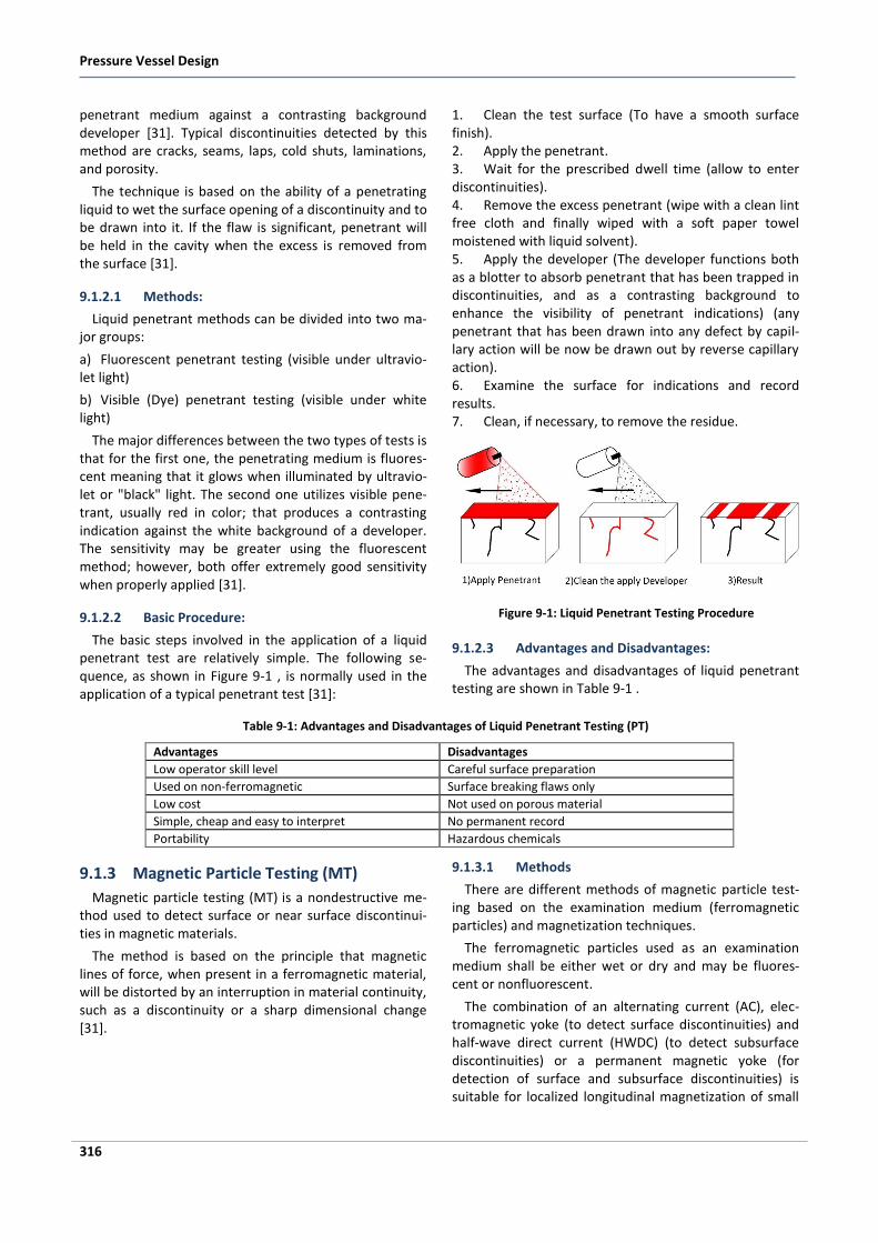
Pressure Vessel Design
316
penetrant medium against a contrasting background developer [31]. Typical discontinuities detected by this method are cracks, seams, laps, cold shuts, laminations, and porosity.
The technique is based on the ability of a penetrating liquid to wet the surface opening of a discontinuity and to be drawn into it. If the flaw is significant, penetrant will be held in the cavity when the excess is removed from the surface [31].
9.1.2.1 Methods:
Liquid penetrant methods can be divided into two ma-jor groups:
a) Fluorescent penetrant testing (visible under ultravio-let light)
b) Visible (Dye) penetrant testing (visible under white light)
The major differences between the two types of tests is that for the first one, the penetrating medium is fluores-cent meaning that it glows when illuminated by ultravio-let or "black" light. The second one utilizes visible pene-trant, usually red in color; that produces a contrasting indication against the white background of a developer. The sensitivity may be greater using the fluorescent method; however, both offer extremely good sensitivity when properly applied [31].
9.1.2.2 Basic Procedure:
The basic steps involved in the application of a liquid penetrant test are relatively simple. The following se-quence, as shown in Figure 9-1 , is normally used in the application of a typical penetrant test [31]:
1. Clean the test surface (To have a smooth surface finish). 2. Apply the penetrant. 3. Wait for the prescribed dwell time (allow to enter discontinuities). 4. Remove the excess penetrant (wipe with a clean lint free cloth and finally wiped with a soft paper towel moistened with liquid solvent). 5. Apply the developer (The developer functions both as a blotter to absorb penetrant that has been trapped in discontinuities, and as a contrasting background to enhance the visibility of penetrant indications) (any penetrant that has been drawn into any defect by capil-lary action will be now be drawn out by reverse capillary action). 6. Examine the surface for indications and record results. 7. Clean, if necessary, to remove the residue.
Figure 9-1: Liquid Penetrant Testing Procedure
9.1.2.3 Advantages and Disadvantages:
The advantages and disadvantages of liquid penetrant testing are shown in Table 9-1 .
Table 9-1: Advantages and Disadvantages of Liquid Penetrant Testing (PT)
Advantages Disadvantages
Low operator skill level Careful surface preparation
Used on non-ferromagnetic Surface breaking flaws only
Low cost Not used on porous material
Simple, cheap and easy to interpret No permanent record
Portability Hazardous chemicals
9.1.3 Magnetic Particle Testing (MT)
Magnetic particle testing (MT) is a nondestructive me-thod used to detect surface or near surface discontinui-ties in magnetic materials.
The method is based on the principle that magnetic lines of force, when present in a ferromagnetic material, will be distorted by an interruption in material continuity, such as a discontinuity or a sharp dimensional change [31].
9.1.3.1 Methods
There are different methods of magnetic particle test-ing based on the examination medium (ferromagnetic particles) and magnetization techniques.
The ferromagnetic particles used as an examination medium shall be either wet or dry and may be fluores-cent or nonfluorescent.
The combination of an alternating current (AC), elec-tromagnetic yoke (to detect surface discontinuities) and half-wave direct current (HWDC) (to detect subsurface discontinuities) or a permanent magnetic yoke (for detection of surface and subsurface discontinuities) is suitable for localized longitudinal magnetization of small
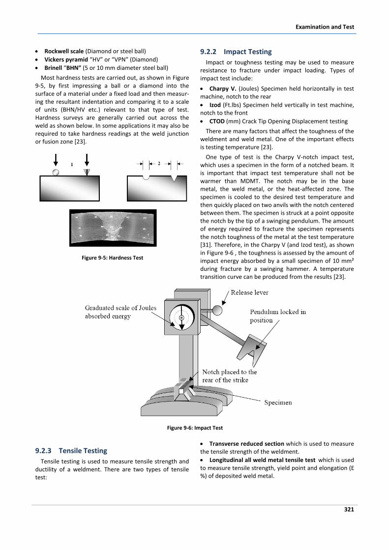
Examination and Test
321
Rockwell scale (Diamond or steel ball)
Vickers pyramid “HV” or “VPN” (Diamond)
Brinell “BHN” (5 or 10 mm diameter steel ball)
Most hardness tests are carried out, as shown in Figure 9-5, by first impressing a ball or a diamond into the surface of a material under a fixed load and then measur-ing the resultant indentation and comparing it to a scale of units (BHN/HV etc.) relevant to that type of test. Hardness surveys are generally carried out across the weld as shown below. In some applications it may also be required to take hardness readings at the weld junction or fusion zone [23].
Figure 9-5: Hardness Test
9.2.2 Impact Testing
Impact or toughness testing may be used to measure resistance to fracture under impact loading. Types of impact test include:
Charpy V. (Joules) Specimen held horizontally in test machine, notch to the rear
Izod (Ft.lbs) Specimen held vertically in test machine, notch to the front
CTOD (mm) Crack Tip Opening Displacement testing
There are many factors that affect the toughness of the weldment and weld metal. One of the important effects is testing temperature [23].
One type of test is the Charpy V-notch impact test, which uses a specimen in the form of a notched beam. It is important that impact test temperature shall not be warmer than MDMT. The notch may be in the base metal, the weld metal, or the heat-affected zone. The specimen is cooled to the desired test temperature and then quickly placed on two anvils with the notch centered between them. The specimen is struck at a point opposite the notch by the tip of a swinging pendulum. The amount of energy required to fracture the specimen represents the notch toughness of the metal at the test temperature [31]. Therefore, in the Charpy V (and Izod test), as shown in Figure 9-6 , the toughness is assessed by the amount of impact energy absorbed by a small specimen of 10 mm² during fracture by a swinging hammer. A temperature transition curve can be produced from the results [23].
Figure 9-6: Impact Test
9.2.3 Tensile Testing
Tensile testing is used to measure tensile strength and ductility of a weldment. There are two types of tensile test:
Transverse reduced section which is used to measure the tensile strength of the weldment.
Longitudinal all weld metal tensile test which is used to measure tensile strength, yield point and elongation (E %) of deposited weld metal.
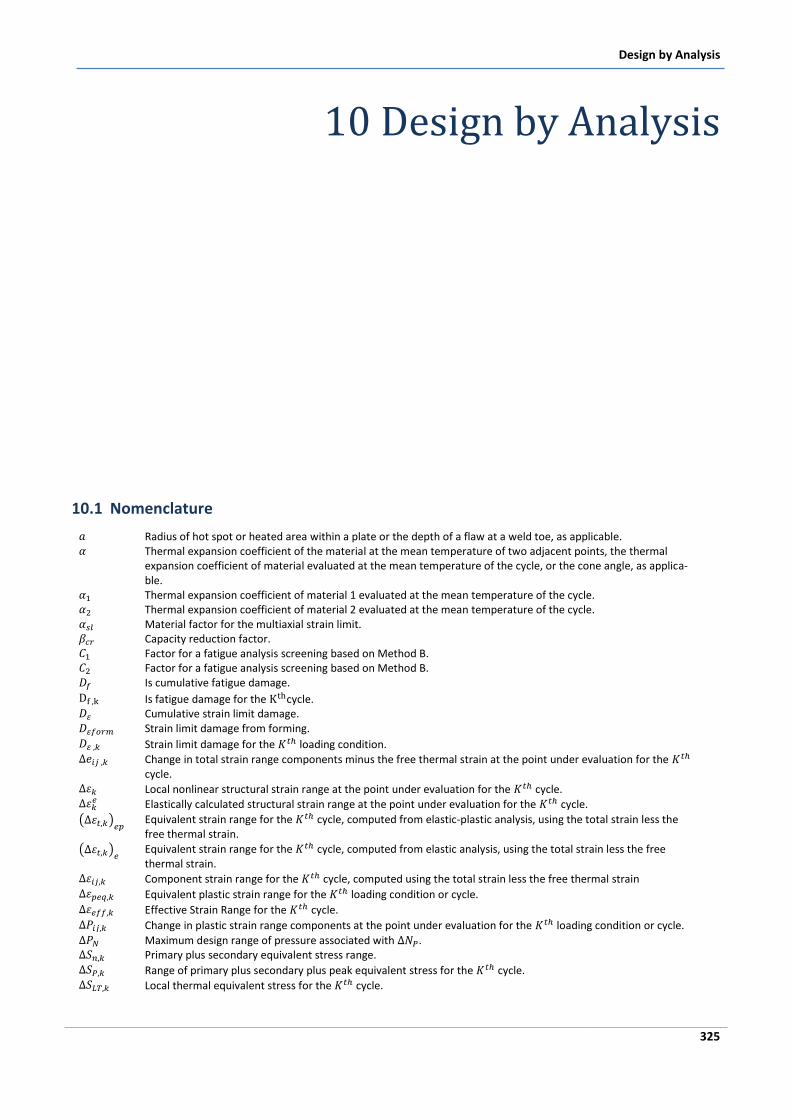
Design by Analysis
325
10 Design by Analysis
10.1 Nomenclature
Radius of hot spot or heated area within a plate or the depth of a flaw at a weld toe, as applicable. Thermal expansion coefficient of the material at the mean temperature of two adjacent points, the thermal
expansion coefficient of material evaluated at the mean temperature of the cycle, or the cone angle, as applica-ble.
Thermal expansion coefficient of material 1 evaluated at the mean temperature of the cycle. Thermal expansion coefficient of material 2 evaluated at the mean temperature of the cycle. Material factor for the multiaxial strain limit. Capacity reduction factor. Factor for a fatigue analysis screening based on Method B. Factor for a fatigue analysis screening based on Method B. Is cumulative fatigue damage.
Is fatigue damage for the cycle. Cumulative strain limit damage. Strain limit damage from forming.
Strain limit damage for the loading condition. Change in total strain range components minus the free thermal strain at the point under evaluation for the
cycle. Local nonlinear structural strain range at the point under evaluation for the cycle.
Elastically calculated structural strain range at the point under evaluation for the cycle.
Equivalent strain range for the cycle, computed from elastic-plastic analysis, using the total strain less the free thermal strain.
Equivalent strain range for the cycle, computed from elastic analysis, using the total strain less the free thermal strain.
Component strain range for the cycle, computed using the total strain less the free thermal strain Equivalent plastic strain range for the loading condition or cycle.
Effective Strain Range for the cycle.
Change in plastic strain range components at the point under evaluation for the loading condition or cycle. Maximum design range of pressure associated with . Primary plus secondary equivalent stress range. Range of primary plus secondary plus peak equivalent stress for the cycle. Local thermal equivalent stress for the cycle.
Design by Analysis
335
b) Limit-Load Method: A calculation is performed to determine a lower bound to the limit load of a compo-nent. The allowable load on the component is established by applying design factors to the limit load such that the
onset of gross plastic deformations (plastic collapse) will not occur [12].
Load case combinations and load factors for a limit load analysis are listed in Table 10-5.
Table 10-5: Load Case Combinations and Load Factors for a Limit Load Analysis [12]
Design condition
Criteria Required Factor Load Combinations
Global Criteria
1.5 (P+Ps+D) 1.3 (P+Ps+D+T) +1.7L+0.54 Ss 1.3 (P+D) + 1.7 Ss + max[1.1L, 0.86W) 1.3 (P+D) + 1.7 W +1.1L +0.54 Ss 1.3 (P+D) + 1.1E +1.1L +0.21 Ss
Local Criteria Per Table 10-6
Serviceability Criteria Per Users Design Specification, if applicable, see Table 10-6
Hydrostatic Test Conditions
Global Criteria Max [1.43, 1.25
]. (P+Ps+D)+2.6 Wpt
Serviceability Criteria Per User’s Design Specification, if applicable.
Pneumatic Test Conditions
Global Criteria 1.5
. (P+Ps+D)+2.6 Wpt
Serviceability Criteria Per User’s Design Specification, if applicable.
Notes:
1. The parameters used in the Design Load Combination column are defined in Table 10-2.
2. S is the allowable membrane stress at the design temperature.
3. ST is the allowable membrane stress at the pressure test temperature.
c) Elastic-Plastic Stress Analysis Method: A collapse load is derived from an elastic-plastic analysis considering both the applied loading and deformation characteristics of the component. The allowable load on the component
is established by applying design factors to the plastic collapse load [12]. Load case combinations and load factors for an elastic-plastic analysis are listed in Table 10-6.
Table 10-6: Load Case Combinations and Load Factors for an Elastic-Plastic Analysis [12]
Design condition
Criteria Required Factor Load Combinations
Global Criteria
2.4 (P+Ps+D) 2.1 (P+Ps+D+T) +2.6L+0.86 Ss 2.1 (P+Ps+D) + 2.6 Ss + max[1.7L, 1.4W) 2.4(P+Ps+D)+ 2.6 W +1.7L +0.86 Ss 2.4 (P+Ps+D)+ 1.7E +1.7L +0.34 Ss
Local Criteria 1.7 (P+Ps+D)
Serviceability Criteria Per Users Design Specification, if applicable, see paragraph
Hydrostatic Test Conditions
Global Criteria Max [2.3, 2.0
]. (P+Ps+D)+ Wpt
Serviceability Criteria Per User’s Design Specification, if applicable.
Pneumatic Test Conditions
Global Criteria 1.8
. (P+Ps+D)+ Wpt
Serviceability Criteria Per User’s Design Specification, if applicable.
Notes:
1. The parameters used in the Design Load Combination column are defined in Table 10-2.
2. S is the allowable membrane stress at the design temperature.
3. ST is the allowable membrane stress at the pressure test temperature.
Design by Analysis
341
fatigue is made on the basis of the number of applied cycles of a stress or strain range at a point in the compo-nent. The allowable number of cycles should be adequate for the specified number of cycles as given in the User’s Design Specification.
Screening criteria are can be used to determine if fati-gue analysis is required as part of a design. If the compo-nent does not satisfy the screening criteria, a fatigue evaluation shall be performed.
Fatigue curves are typically presented in two forms: fatigue curves that are based on smooth bar test speci-mens and fatigue curves that are based on test speci-mens that include weld details of quality consistent with the fabrication and inspection requirements of [12].
Smooth bar fatigue curves may be used for compo-nents with or without welds. The welded joint curves shall only be used for welded joints.
The smooth bar fatigue curves are applicable up to the maximum number of cycles given on the curves. The welded joint fatigue curves do not exhibit an endurance limit and are acceptable for all cycles.
If welded joint fatigue curves are used in the evalua-tion, and if thermal transients result in a through thick-ness stress difference at any time that is greater than the steady state difference, the number of design cycles shall be determined as the smaller of the number of cycles for the base metal established using either Fatigue Assess-ment – Elastic Stress Analysis and Equivalent Stresses or Fatigue Assessment – Elastic-Plastic Stress Analysis and Equivalent Strains, and for the weld established in accor-dance with Fatigue Assessment of Welds – Elastic Analy-sis and Structural Stress.
Stresses and strains produced by any load or thermal condition that does not vary during the cycle need not be considered in a fatigue analysis if the fatigue curves utilized in the evaluation are adjusted for mean stresses and strains. The design fatigue curves of Fatigue Assess-ment – Elastic Stress Analysis and Equivalent Stresses and Fatigue Assessment – Elastic-Plastic Stress Analysis and Equivalent Strains are based on smooth bar test speci-mens and are adjusted for the maximum possible effect of mean stress and strain; therefore, an adjustment for mean stress effects is not required. The fatigue curves of Fatigue Assessment of Welds – Elastic Analysis and Structural Stress are based on welded test specimens and include explicit adjustments for thickness and mean stress effects.
Under certain combinations of steady state and cyclic loadings there is a possibility of ratcheting. A rigorous evaluation of ratcheting normally requires an elastic-plastic analysis of the component; however, under a limited number of loading conditions, an approximate analysis can be utilized based on the results of an elastic stress analysis.
Protection against ratcheting shall be considered for all operating loads listed in the User’s Design Specification and shall be performed even if the fatigue screening criteria are satisfied.
Protection against ratcheting is satisfied if one of the following three conditions is met [12]:
The loading results in only primary stresses without any cyclic secondary stresses.
Elastic Stress Analysis Criteria: Protection against ratcheting is demonstrated by satisfying the rules of Ratcheting Assessment – Elastic Stress Analysis.
Elastic-Plastic Stress Analysis Criteria: Protection against ratcheting is demonstrated by satisfying the rules of Ratcheting Assessment – Elastic-Plastic Stress Analysis.
10.7.5.2 Screening Criteria for Fatigue Analysis
The provisions of screening criteria can be used to de-termine if a fatigue analysis is required as part of the vessel design. The screening options to determine the need for fatigue analysis are described below. If any one of the screening options is satisfied, then a fatigue analy-sis is not required as part of the vessel design.
The fatigue exemption is performed on a component or part basis. One component (integral) may be exempt, while another component (non-integral) is not exempt. If any one component is not exempt, then a fatigue evalua-tion shall be performed for that component. Further-more, if the specified number of cycles is greater than 10
6, then the screening criteria are not applicable and a
fatigue analysis is required.
Fatigue Analysis Screening Based On Experience with Comparable Equipment:
If successful experience over a sufficient time frame is obtained and documented with comparable equipment subject to a similar loading histogram, then a fatigue analysis is not required as part of the vessel design. When evaluating experience with comparable equipment operating under similar conditions as related to the design and service contemplated, the possible harmful effects of the following design features shall be eva-luated.
The use of non-integral construction, such as the use of pad type reinforcements or of fillet welded attach-ments, as opposed to integral construction
The use of pipe threaded connections, particularly for diameters in excess of 70 mm (2.75 in.)
The use of stud bolted attachments
The use of partial penetration welds
Major thickness changes between adjacent members
Attachments and nozzles in the knuckle region of formed heads
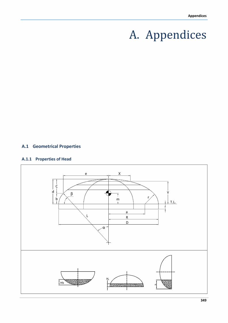
Appendices
349
A. Appendices
A.1 Geometrical Properties
A.1.1 Properties of Head
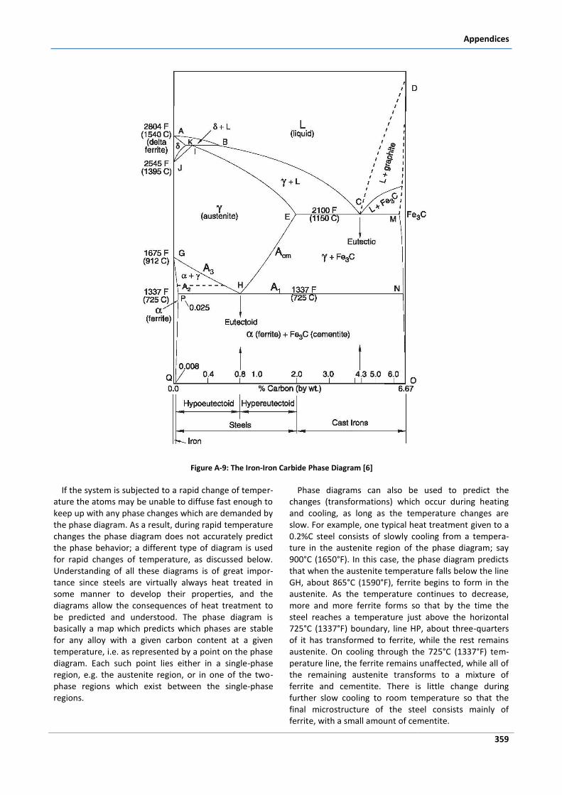
Appendices
359
Figure A-9: The Iron-Iron Carbide Phase Diagram [6]
If the system is subjected to a rapid change of temper-ature the atoms may be unable to diffuse fast enough to keep up with any phase changes which are demanded by the phase diagram. As a result, during rapid temperature changes the phase diagram does not accurately predict the phase behavior; a different type of diagram is used for rapid changes of temperature, as discussed below. Understanding of all these diagrams is of great impor-tance since steels are virtually always heat treated in some manner to develop their properties, and the diagrams allow the consequences of heat treatment to be predicted and understood. The phase diagram is basically a map which predicts which phases are stable for any alloy with a given carbon content at a given temperature, i.e. as represented by a point on the phase diagram. Each such point lies either in a single-phase region, e.g. the austenite region, or in one of the two-phase regions which exist between the single-phase regions.
Phase diagrams can also be used to predict the changes (transformations) which occur during heating and cooling, as long as the temperature changes are slow. For example, one typical heat treatment given to a 0.2%C steel consists of slowly cooling from a tempera-ture in the austenite region of the phase diagram; say 900°C (1650°F). In this case, the phase diagram predicts that when the austenite temperature falls below the line GH, about 865°C (1590°F), ferrite begins to form in the austenite. As the temperature continues to decrease, more and more ferrite forms so that by the time the steel reaches a temperature just above the horizontal 725°C (1337°F) boundary, line HP, about three-quarters of it has transformed to ferrite, while the rest remains austenite. On cooling through the 725°C (1337°F) tem-perature line, the ferrite remains unaffected, while all of the remaining austenite transforms to a mixture of ferrite and cementite. There is little change during further slow cooling to room temperature so that the final microstructure of the steel consists mainly of ferrite, with a small amount of cementite.
Pressure Vessel Design
360
It is important to remember that all of these heat treatments which involve the cooling of austenite occur completely in the solid state. Austenite is a solid, as are its transformation products when it is cooled. This type of heat treatment is typically carried out after the ma-terial has been formed into its final or near-final shape [6].
A.2.3 Heat Treating of Steel -The Effects of
Carbon Content and Cooling Rate
The heat treating of steel normally begins with heating into the austentite temperature range and allowing the pre-existing microstructure to transform fully to auste-nite as required by the phase diagram. This austenitizing process may be carried out in any one of a number of atmospheres including air, inert gas, vacuum or molten salt. The hot austenitic steel is then cooled at some rate ranging from rapid (e.g. thousands of degrees per second by quenching in chilled brine) to slow (e.g. as little as a few degrees per hour by furnace cooling in a hot furnace which is allowed to cool with the steel inside). It is important to remember that the cooling rate is normally not uniform throughout the cross-section of the steel object, particularly at rapid cooling rates. The inside of a thick section can only cool by conducting its heat to the surface, where it is removed into the cooling medium; this is always a relatively slow process. The consequence is that if a thick section of steel is quenched, its surface undergoes a much higher cooling rate than its center. Therefore, the surface and the center can have different microstructures and proper-ties. Furthermore, there will be residual stresses in the material associated with this situation. These effects can be beneficial or detrimental to the application of the material.
During cooling the austenite becomes unstable, as predicted by the phase diagram, and decomposes or transforms to form a different microstructure, the characteristics of which depend on the austenitization conditions, the carbon content and the cooling rate. There are also effects due to the presence of other alloying elements.
Several effects of increased cooling rate on the forma-tion of ferrite pearlite microstructures have already been alluded to, namely the different morphologies of proeu-tectoid ferrite, and the increasing fineness of the pear-lite. However, if cooling rates are increased still further, the limited time available during cooling is insufficient to permit the atom diffusion which is necessary for pearlite to form. As a result, microstructural constituents other than pearlite form when the austenite, which has be-come unstable below the A1 temperature, transforms. These transformation products, including bainite and martensite, are nonequilibrium constituents which are therefore not present on the (equilibrium) phase dia-
gram. Their formation occurs by processes which rely only partially (bainite), or alternatively not at all (mar-tensite), on the diffusion of atoms. Thus martensite and bainite are able to form even at rapid cooling rates [6].
Bainite Formation
Bainite is a constituent which forms from austenite in a temperature range below about 535°C (1000°F) and above a critical temperature (the Ms temperature, discussed below) which depends on carbon content and is about 275°C (525°F) for eutectoid steel.
Martensite Formation
If austenite can be cooled to a sufficiently low temper-ature, for example by cooling very rapidly, its diffusion-controlled transformation to ferrite, pearlite or even bainite will not be possible. Instead, the austenite becomes so unstable that it is able to change its crystal structure by a diffusionless shearing transformation which moves blocks of atoms by small distances simulta-neously. The transformation product is then martensite, a metastable phase which, like bainite, does not appear on the phase diagram since it does not exist under equilibrium conditions.
Tempered Martensite
Although martensite is a very hard, strong, wear resis-tant material it lacks ductility and toughness, so much so that in all but low carbon steels brittle failure of marten-site is so easily initiated that its strength cannot normally even be measured. Thus, a steel through-hardened (transformed to martensite throughout its thickness) is not a satisfactory engineering material for most applica-tions. However, a surface layer of martensite on a tougher ferrite-pearlite base can provide useful proper-ties. Furthermore, and even more usefully, martensite can be heat treated by tempering to obtain a tempered martensite microstructure with properties which are appropriate for industrial purposes. The extent of tem-pering and hence the mechanical properties can be controlled by varying the tempering time and tempera-ture.
Hardenability
It is important to distinguish clearly between the terms "hardness" and "hardenability". Hardness is the resis-tance of a surface to being indented by an indenter under standard conditions, such as in the Rockwell or Brinell hardness tests. The hardness of steel is deter-mined by its composition and its microstructure (i.e. its thermo-mechanical processing). Hardenability, on the other hand, refers to the ability of a steel to harden, i.e. to form martensite to depth. This corresponds to the steel having a low critical cooling rate, i.e. having the ability to form martensite at low cooling rates. Steels with low hardenability are those which form only a thin surface layer of martensite when quenched from the austenite.
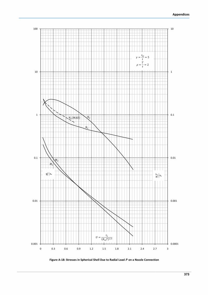
Appendices
373
Figure A-18: Stresses in Spherical Shell Due to Radial Load on a Nozzle Connection
0.0001
0.001
0.01
0.1
1
10
0.001
0.01
0.1
1
10
100
0 0.3 0.6 0.9 1.2 1.5 1.8 2.1 2.4 2.7 3
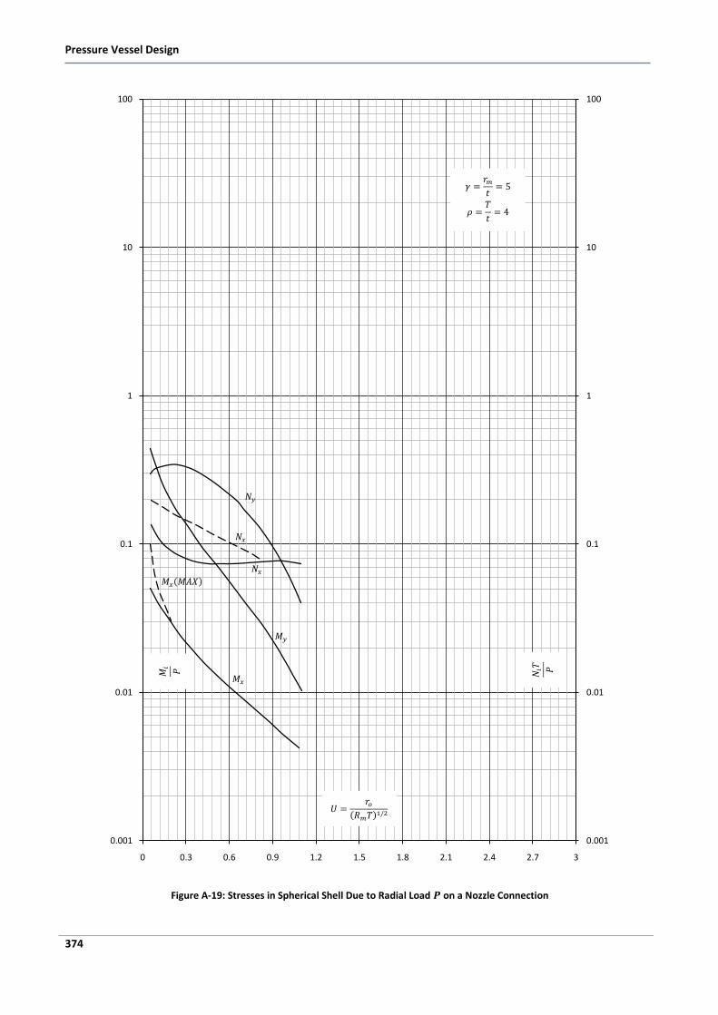
Pressure Vessel Design
374
Figure A-19: Stresses in Spherical Shell Due to Radial Load on a Nozzle Connection
0.001
0.01
0.1
1
10
100
0.001
0.01
0.1
1
10
100
0 0.3 0.6 0.9 1.2 1.5 1.8 2.1 2.4 2.7 3
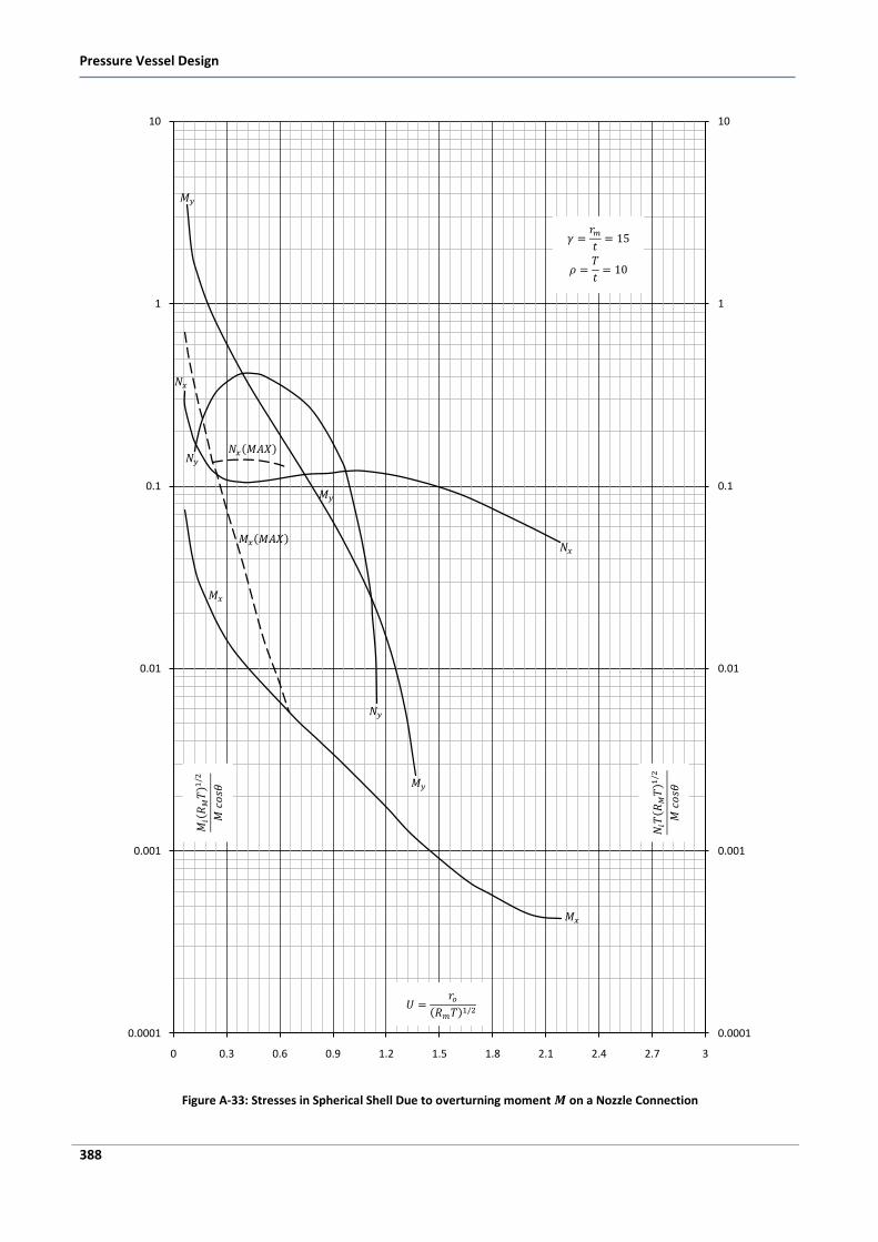
Pressure Vessel Design
388
Figure A-33: Stresses in Spherical Shell Due to overturning moment on a Nozzle Connection
0.0001
0.001
0.01
0.1
1
10
0.0001
0.001
0.01
0.1
1
10
0 0.3 0.6 0.9 1.2 1.5 1.8 2.1 2.4 2.7 3
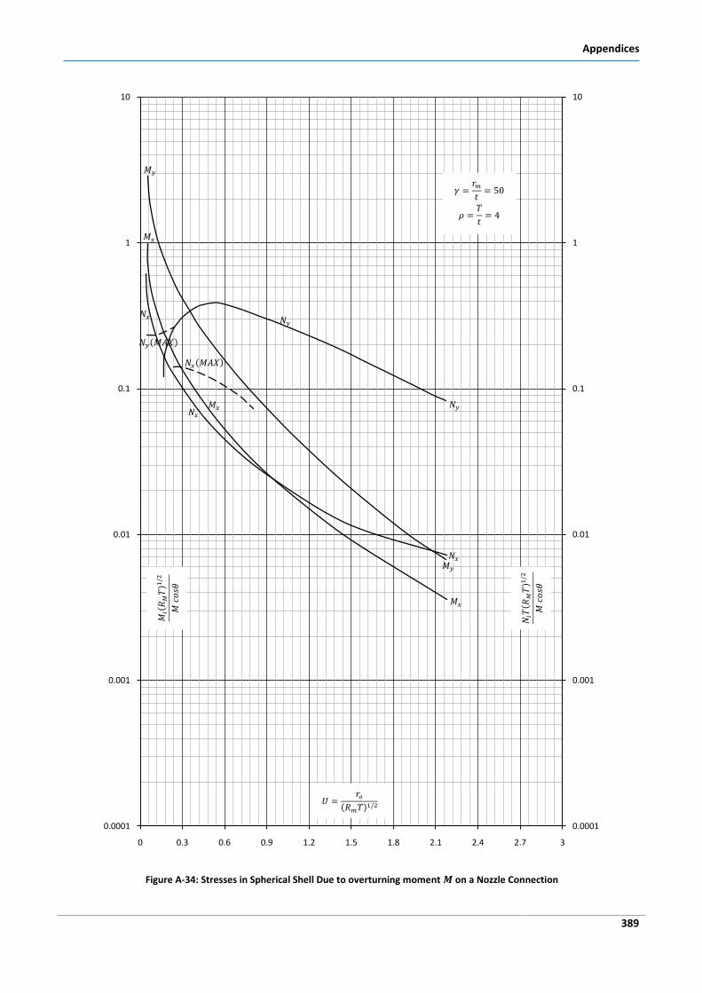
Appendices
389
Figure A-34: Stresses in Spherical Shell Due to overturning moment on a Nozzle Connection
0.0001
0.001
0.01
0.1
1
10
0.0001
0.001
0.01
0.1
1
10
0 0.3 0.6 0.9 1.2 1.5 1.8 2.1 2.4 2.7 3
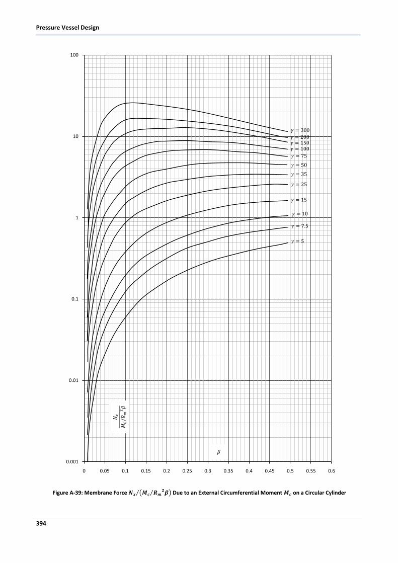
Pressure Vessel Design
394
Figure A-39: Membrane Force Due to an External Circumferential Moment on a Circular Cylinder
0.001
0.01
0.1
1
10
100
0 0.05 0.1 0.15 0.2 0.25 0.3 0.35 0.4 0.45 0.5 0.55 0.6
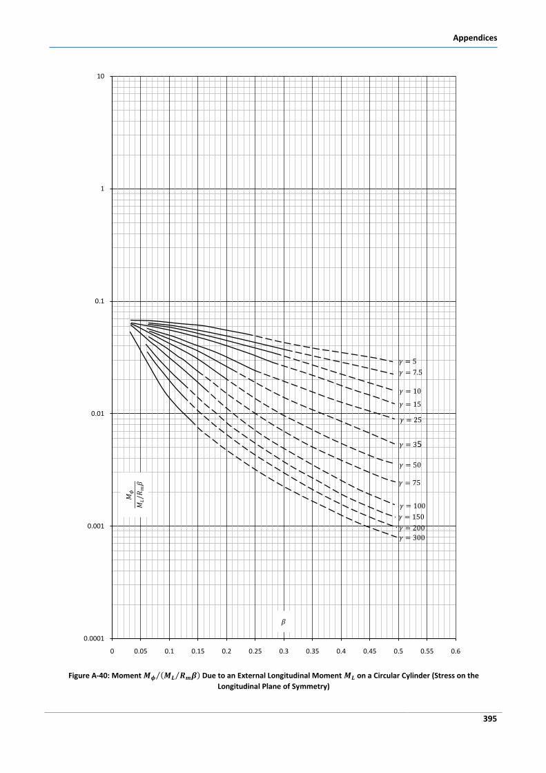
Appendices
395
Figure A-40: Moment Due to an External Longitudinal Moment on a Circular Cylinder (Stress on the
Longitudinal Plane of Symmetry)
0.0001
0.001
0.01
0.1
1
10
0 0.05 0.1 0.15 0.2 0.25 0.3 0.35 0.4 0.45 0.5 0.55 0.6
5
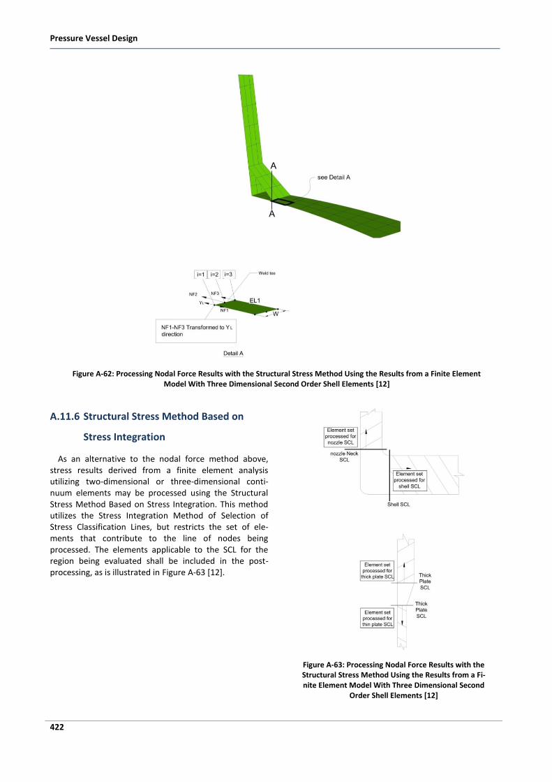
Pressure Vessel Design
422
Figure A-62: Processing Nodal Force Results with the Structural Stress Method Using the Results from a Finite Element Model With Three Dimensional Second Order Shell Elements [12]
A.11.6 Structural Stress Method Based on
Stress Integration
As an alternative to the nodal force method above, stress results derived from a finite element analysis utilizing two-dimensional or three-dimensional conti-nuum elements may be processed using the Structural Stress Method Based on Stress Integration. This method utilizes the Stress Integration Method of Selection of Stress Classification Lines, but restricts the set of ele-ments that contribute to the line of nodes being processed. The elements applicable to the SCL for the region being evaluated shall be included in the post-processing, as is illustrated in Figure A-63 [12].
Figure A-63: Processing Nodal Force Results with the Structural Stress Method Using the Results from a Fi-nite Element Model With Three Dimensional Second
Order Shell Elements [12]

<Bibliography
423
Bibliography
1. Matthews, Clifford. Engineers’ Guide to Pressure Equipment. London : Professional Engineering Publishing, 2001.
2. Chattopadhyay, Somnath. Pressure Vessel Design and Practice. s.l. : CRC Press, 2005.
3. Carruci, Vincent A. Overview of Pressure Vessel Design. s.l. : ASME International, 1999.
4. ASME, The American Society of Mechanical Engineers. Rules for Construction of Pressure Vessels (Sec. VIII, Division 1). ASME Boiler and Pressure Vessel Code. New York : ASME (The American Society of Mechanical Engineers), 2007.
5. Ellenberger, J. Phillip, Chuse, Robert and Carson, Bryce E. Pressure Vessels: The ASME Code Simplified. 8th Edition. s.l. : McGraw-Hill, 2004.
6. Bringas, John E. The Metals Black Book. Edmonton, Alberta : CASTI Publishing Inc, 1995.
7. Moen, Richard A. Practical Guidebook Series™ ASME Section II 1997 Materials Index. Edmonton, Alberta : CASTI Publishing Inc., 1996.
8. Perry, R. H., and Chilton, C. H. Perry’s Chemical Engineer’s Handbook, 5th ed. New York : McGraw-Hill, 1973.
9. White, R. A. and Ehauke, E. F. Materials Selection for Refineries and Associated Facilities. San Francisco, California : s.n.
10. Bednar, Henry H. Pressure Vessel Design Handbook. 2nd Edition. Malabar, Florida : Krieger Publishing Company, 1986.
11. Moss, Dennis R. Pressure Vessel Design Manual. 3rd Edition. Burlington : Gulf Professional Engineering, 2004.
12. ASME, The American Society of Mechanical Engineers. Rules for Construction of Pressure Vessels-Alternative Rules (Sec. VIII, Division 2). ASME Boiler and Pressure Vessel Code. New York : ASME (The American Society of Mechanical Engineers), 2007.
13. COADE, Engineering Physics Software. 2007 PV-Elite User Guide. Huston, Texas : COADE/Engineering Physics Software, 2007.
14. Megyesy, Eugene F. Pressure Vessel Handbook. 10th Edition. s.l. : Pressure Vessel Handbook Publishing, Inc., 2001.
15. Ventsel, Eduard and Krauthammer, Theodor. Thin Plates and Shells, Theory, Analysis, and Applications. New York : Marcel Decker, Inc., 2001.
16. Steffens, Franz-Joseph Barthold & Alexander. Introductory Course in Structural Analysis.
17. Timoshenko, Stephen P. and Woinowsky-Krieger, S. Theory of Plates and Shells. 2nd Edition. LA : Mc-Graw Hill, 1975.
18. Jawad, Maan H. and Farr, James R. Structural Analysis and Design of Process Equipment. s.l. : John Wiley & Sons, Inc., 1984.
Pressure Vessel Design
424
19. Wichman, K. R., Hopper, A. G. and Mershon, J. L. Welding Research Council (bulletin No.107), Local Stresses in Spherical and Cylindrical Shells due to External Loadings. New York : Welding Research Council, Inc., 1979.
20. ASCE, American Society of Civil Engineers. Minimum Design Loads for Buildings and Other Structures. Reston, Virginia : American Society of Civil Engineers, 2006.
21. UBC, Uniform Building Code. Structural Design Requirements (Chapter 16). Uniform Building Code. 1997.
22. Ibrahim Khan, Md. Welding Science and Technology. New Delhi : New Age International, 2007.
23. TWI, The Welding Institute. TWI WIS 5, Welding Inspection of Steels. Cambridge : TWI Ltd, 2007.
24. Hicks, John. Welded joint design. New York : Industrial Press, Inc, 1999.
25. Weman, Klas. Welding Processes Handbook. Cambridge : Woodhead Publishing Ltd, 2003.
26. Pullarcot, Sunil. Practical Guide to Pressure Vessel Manufacturing. New York : Marcel Dekker, Inc., 2002.
27. Funderburk, R. Scott. Key Concepts in Welding Engineering, Postweld Heat Treatment. Welding Innovation. 1998.
28. API. API 941 (Steels for Hydrogen Service at Elevated Temperatures and Pressures in Petroleum Refineries and Petrochemical Plants). Washington D.C. : API Publishing Services (American Petroleum Institute), 2004.
29. —. API 945 (Avoiding Environment Cracking in Amine Units). Washington D.C. : API Publishing Services (American Petroleum Institute), 2003.
30. ASME, The American Society of Mechanical Engineers. Welding and Brazing Qualifications (Sec. IX, Division 1). ASME Boiler and Pressure Vessel Code. New York : ASME (The American Society of Mechanical Engineers), 2007.
31. AWS, American Welding Society. AWS Welding Handbook, Engineering, Costs, Quality, and Safety. 7th Edition. Miami : AWS, 1997.
32. ASME, PCC-2. Repair of Pressure Equipment and Piping. New York : ASME (The American Society of Mechanical Engineers), 2006.
33. Taylor N., etal. The design-by-analysis manual CEC. Report EUR 19020 EN, DG-JRC/IAM, Petten. s.l. : EPERC, 1999.
34. Shiraga, Scott. Design and Development Guide for NNSA Type B Packages SG-100 Revision 2, Appendix K “Differences in Vessel Design by Rule and Design by Analysis”. s.l. : NNSA, 2005.
35. ASM. Handbook Vol. 1, Properties and Selection: Irons, Steels, and High Performance Alloys. s.l. : ASM International, 2005.
36. Bradford, Samuel A. Practical Self Study Guide to Corossion Control. Edmonton, Alberta : CASTI Publishing Inc, 1998.

Index
425
Index
A
AISC Steel Construction Manual · 207, 208 Anchor bolt · 18, 215, 219, 220, 222, 224, 238, 239, 246, 284 Annealing · 362 Apex angle · 97, 98, 101, 103, 115, 143, 350 Arc Welding · 308 ASCE · 12, 14, 206, 330 ASME section II · 35, 77 ASME section IX · 41, 42, 314 ASME section VIII · 13, 14, 60, 61 Attachments · 6, 7, 17, 130, 134, 147, 150, 152, 153, 155, 158, 159, 208, 211, 300, 309, 312, 313, 331, 341, 342 Austenitic · 25, 27, 33, 35, 40, 42, 47, 51, 52, 53, 54, 55, 56, 57, 60, 61, 169, 339, 360, 361, 362, 407 AWS · 12, 24, 28 Axial stress · 242, 259
B
Baffle · 52, 74 Bainite · 360 Base plate · 52, 208, 209, 215, 222, 223, 224, 235, 238, 239, 244, 245, 246, 260, 284 Beams · 208, 232, 261, 317 Bend testing · 320, 322 Bending moment · 143, 148, 151, 152, 156, 157, 219, 230, 260, 261, 326, 333, 334, 352
Bending stress · 66, 143, 148, 152, 157, 215, 223, 230, 231, 234, 239, 242, 244, 245, 259, 326, 327, 331, 334, 416, 417, 418, 420 Bijlaard · 148, 149, 150, 152, 155, 209, 261 Bins · 207 Body flange · 86 Bolt load · 184, 188, 189, 203, 218 Bolt stress · 184 Braces · 207 Brackets · 13, 28, 41, 74, 169, 332 Brittle fracture · 58, 323, 329 Buckle · 52, 65, 69, 80 Buckling load · 340 Butt weld · 99, 101, 126, 129, 185, 297, 298, 299, 300, 304, 307, 320
C
Carbon steel · 10, 24, 25, 26, 28, 34, 44, 47, 51, 52, 53, 115, 197, 203, 297, 310, 312, 313, 356, 357, 361, 364 Carbon steel plate · 51 Center of gravity · 16, 17, 215, 239, 242, 246, 247, 261, 280, 281 Charpy V · 321 Circumferential moment · 156, 157, 248, 249, 253, 254, 391, 392, 393, 394 Circumferential stress · 68, 121, 216, 352 Circumferential welded joints · 305 Clips · 14, 51, 54, 208 Coefficient · 34, 52, 53, 149, 210, 213, 227, 241, 249, 250, 327, 342, 350

Pressure Vessel Design
426
Coils · 3 Collapse · 65, 69, 80, 212, 329, 330, 334, 335, 336, 337, 338, 340, 414, 415 Columns · 4, 6, 33, 37, 38, 39, 207, 208, 323, 339 Composite · 188, 209 Compression plate · 209, 218, 219, 220, 246, 260, 261 Compression ring · 208, 218, 223 Concentration factor · 148, 149, 153, 254, 258 Cone to cylinder · 98, 101 Conical · 5, 63, 71, 77, 86, 96, 97, 98, 99, 100, 101, 109, 118, 119, 120, 129, 143, 207, 333 Corrosion · 12, 15, 25, 32, 40, 43, 100, 286, 329, 362, 363, 364, 367 Corrosive · 44, 51, 53, 54, 55, 56, 57, 196, 361 Creep · 31, 47, 53, 56, 196, 329, 362 Critical · 27, 43, 58, 61, 69, 80, 207, 317, 323, 329, 340, 360 Cross brace · 207 CTOD · 321 Cyclic · 51, 60, 65, 207, 208, 239, 303, 326, 330, 334, 336, 340, 341, 342, 343, 413 Cylindrical · 3, 4, 5, 6, 13, 63, 64, 65, 67, 68, 69, 70, 71, 77, 80, 86, 98, 115, 117, 118, 119, 120, 121, 124, 129, 143, 148, 149, 150, 153, 154, 155, 172, 207, 224, 225, 226, 228, 229, 230, 231, 331, 340
D
Damping · 206, 260, 261 Data sheet · 16, 17 Defect evaluation · 412 Deflection · 149, 154, 214, 215, 247, 280, 281, 338 Density · 34, 40, 62, 87, 205, 286, 318, 319, 353, 357, 418 Design pressure · 13, 44, 60, 65, 67, 69, 72, 80, 86, 96, 97, 100, 121, 135, 142, 184, 188, 194, 202, 224, 327, 332, 342, 343 Design procedure · 19, 72, 77, 81, 100, 104, 105, 106, 107, 108, 159, 197, 208, 215, 224, 239, 247, 261, 287, 334 Design temperature · 38, 44, 45, 52, 53, 61, 67, 71, 72, 77, 80, 86, 87, 96, 98, 101, 184, 188, 194, 211, 224, 229, 230, 232, 246, 281, 286, 322, 327, 335 Dew point · 47, 146 Discontinuity · 80, 103, 104, 115, 207, 209, 312, 316, 323, 326, 331, 333, 414, 415 Dished head · 13, 15, 98, 115, 333, 342 Displacement · 60, 65, 211, 321, 330, 333, 336, 337, 352 Division 1 · 3, 9, 10, 11, 12, 13, 33, 34, 38, 58, 59, 60, 61, 62, 68, 87, 328 Division 2 · 9, 10, 12, 13, 14, 33, 34, 38, 39, 58, 59, 60, 61, 68 Division 3 · 9, 10 Downcomer · 80 Draining · 69, 117 Drums · 2, 3, 6, 63 Ductility · 320 Dynamic · 14, 24, 65, 210, 213, 353
E
Elastic deformation · 65, 329, 337
Elasticity · 34, 39, 40, 65, 67, 87, 96, 97, 148, 194, 211, 215, 224, 239, 246, 286, 326, 352, 353 Elastic-plastic · 325, 326, 328, 335, 337, 338, 339, 340, 341, 415 Electrode · 9, 28, 32, 57, 299, 300, 308, 309, 310, 324, 407 Ellipsoidal head · 96, 97, 98, 99, 100, 109, 121 Elliptical · 86, 109, 115, 120, 147, 168, 210, 224, 228, 229, 338, 340 Empty weight · 205, 280 Erection · 17, 18, 205, 207, 280 Euler · 80 Examination · 3, 9, 12, 42, 143, 146, 307, 308, 315, 316, 318 Expansion · 6, 31, 34, 39, 48, 51, 52, 53, 65, 117, 174, 208, 209, 311, 325, 327, 332, 334, 342 External pressure · 10, 13, 16, 17, 32, 33, 34, 38, 39, 40, 62, 65, 67, 68, 69, 70, 71, 72, 74, 75, 77, 80, 83, 84, 86, 87, 90, 91, 96, 97, 98, 99, 100, 101, 102, 103, 104, 106, 107, 108, 109, 112, 113, 114, 117, 125, 142, 150, 154, 171, 194, 209, 215, 216, 219, 224, 232, 286, 307, 331, 340 External ring · 75
F
Fabricated weight · 205, 280 Fabrication · 3, 8, 9, 10, 11, 13, 16, 17, 23, 36, 37, 43, 47, 51, 58, 115, 143, 207, 223, 297, 308, 309, 310, 311, 312, 313, 315, 322, 323, 339, 341 Failures · 69, 211, 322 Fatigue analysis · 325, 326, 328, 329, 341, 342, 343, 344 Ferritic · 11, 25, 27, 33, 42, 47, 51, 52, 53, 55, 57, 58, 230, 313, 339, 407 Ferrous Materials · 41 Filler metal · 9, 28, 32, 301, 309, 310, 314 Fillet weld · 75, 76, 124, 133, 134, 135, 138, 139, 171, 176, 297, 299, 303, 417, 420, 421 Finite element analysis · 13, 16, 413, 414, 416, 417, 418, 420, 422 Fitting · 10, 32, 35, 36, 41, 42, 59, 133, 134, 135, 138, 145, 146 Flanges · 2, 12, 13, 15, 32, 41, 52, 53, 60, 134, 146, 169, 183, 184, 185, 186, 187, 188, 189, 193, 194, 195, 196, 197, 305 Flat head · 15, 86, 101, 120, 124, 125, 126, 127, 128, 305, 329, 333 Flat plate · 342 Flowchart · 21, 81, 82, 83, 84, 85, 87, 88, 89, 90, 91, 92, 93, 97, 198, 261, 262, 263, 264, 265, 266, 267, 268, 269, 270, 271, 272, 273, 274, 275, 276, 277, 278, 279, 288, 289, 290, 291, 292, 293, 294, 295, 344, 345, 346, 347, 348 Force method · 211, 422 Formulas · 10, 11, 65, 67, 68, 71, 72, 77, 87, 96, 98, 99, 122, 123, 125, 153, 159, 189, 193, 194, 206, 211, 214, 215, 216, 223, 224, 234, 242, 247, 250, 255, 256, 258, 261, 280, 281, 283, 284, 285, 308, 329, 350 Friction · 208, 232, 237, 261, 283 Friction factor · 232
G
Gas Metal Arc Welding (GMAW) · 309

Index
429
V
Valve · 2, 32, 41, 53, 189 Vertical vessel · 74, 213, 214, 249 Vibration · 208, 211, 214, 215, 216, 239, 242, 247, 281, 330 Visual · 14, 18, 133, 315, 322 Visual Testing (VT) · 315 Vortex · 7, 210
W
Weld neck · 199 Weld overlay · 51, 52 Welding · 9, 12, 13, 14, 15, 17, 18, 24, 28, 32, 33, 38, 39, 41, 42, 43, 47, 51, 52, 55, 56, 57, 58, 60, 72, 75, 80, 101, 133, 134, 138, 145, 146, 148, 185, 205, 207, 208, 209, 297, 299, 300, 301, 303, 306, 308, 309, 310, 311, 312, 313, 314, 320, 323, 324, 407 Wind · 6, 13, 14, 16, 17, 65, 68, 69, 79, 80, 97, 206, 209, 210, 211, 215, 216, 224, 242, 247, 248, 261, 263, 280, 281, 286, 290, 329, 330
WPS · 17, 18, 313, 314 WRC · 12, 13, 15, 19, 148, 149, 166, 167, 174, 175, 182, 209, 244, 258, 284, 285, 368
X
X-ray · 319, 320, 407
Y
Yield · 25, 30, 31, 33, 36, 38, 39, 41, 42, 47, 52, 53, 56, 62, 65, 69, 80, 142, 208, 215, 239, 246, 287, 311, 321, 322, 327, 328, 329, 331, 336, 337, 338, 339, 367
Z
Zick’s analysis · 208, 224 Zick’s stress · 208