pulsed x ray
DESCRIPTION
x raysTRANSCRIPT
“Demonstration of Pulsed X-ray Machine Radiography as an Alternative to Industry Radiography Cameras,
Demonstration Pilot Project”
Draft Final Report SwRI® Project 14.12444
Prepared for
U. S. Environmental Protection Agency Radiation Protection Division
1200 Pennsylvania Avenue, N.W. Mail Drop: 6608J
Washington, DC 20460
Prepared by
Sensor Systems and NDE Technology Department Applied Physics Division
Southwest Research Institute®
6220 Culebra Road San Antonio, Texas 78238
November 2006
SOUTHWEST RESEARCH INSTITUTE SAN ANTONIO HOUSTONDETROIT WASHINGTON, DC

iii
TABLE OF CONTENTS
PAGE
1. BACKGROUND ........................................................................................................................ 1 2. TECHNICAL APPROACH........................................................................................................ 2 3. SCOPE OF WORK..................................................................................................................... 3
3.1 Isotopic Source and Pulsed X-ray Source....................................................................... 3 3.2 Work Conducted ............................................................................................................. 4 3.3 Discussion ....................................................................................................................... 6 3.4 Impact to End-Users ..................................................................................................... 21
4. COMMERCIALIZATION PLAN............................................................................................ 22 5. CONCLUSIONS....................................................................................................................... 23

iv
LIST OF FIGURES FIGURE PAGE
1 Illustration of double-sided pipeline radiography used to inspect pipeline welds........ 2
2 Photograph of a gamma ray camera.............................................................................. 3
3 Specifications for XRS-3 Pulsed X-ray Source ............................................................ 4
4 Illustration of source size and film/detector set used for the isotopic and pulsed x-ray sources ................................................................................................................. 6
5 Photographs of portions of each pipe size showing some types of defects generated in the welds ................................................................................................................... 7
6 Photograph showing isotopic source being used to take single-wall radiographs........ 7
7 Photograph showing isotopic source used for double wall radiographs....................... 8
8 Pulsed x-ray source with Vidisco real-time imaging used for double wall radiographs.................................................................................................................... 8
9 Single wall isotopic radiograph on 16-inch-diameter pipe ........................................... 9
10 Double wall isotopic radiograph on 16-inch-diameter pipe ....................................... 15
11 Composite real-time images obtained using the XRS-3 pulsed x-ray source and the Vidisco imaging system........................................................................................ 15
12 Digital image on pipe showing six detectable wires on the IQI ................................. 19
13 Illustration of defects reported in the 4-inch-diameter pipe weld for both isotopic and pulsed x-ray radiography...................................................................................... 19
14 Illustration of defects reported in the 6-inch-diameter pipe weld for both isotopic and pulsed x-ray radiography...................................................................................... 20
15 Illustration of defects reported in the 10-inch-diameter pipe weld for both isotopic and pulsed x-ray radiography...................................................................................... 20
16 Photograph of isotopic source on pipe during radiography........................................ 21
1
1. BACKGROUND
The Radiation Protection Division of the Environmental Protection Agency (EPA) is dedicated
to minimizing incidences of lost radioactive sources that enter into consumer metal supplies and
the public domain. Industrial devices and consumer products containing radioactive sources
routinely fall out of regulatory control. Once out of regulatory control, these devices and
products may be subjected to harsh conditions capable of producing a breached source, with the
potential of harmful exposure incidents and significant economic impacts to industry.
Providing alternative technologies for devices and products which utilize radioactive sources is
one approach to minimize lost source incidences. The current focus of EPA’s efforts in this
regard is to conduct those studies and assessments necessary to support the implementation of
such alternative technologies in industrial practices – alternatives that are technologically and
economically advantageous.
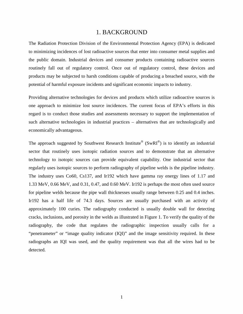
The approach suggested by Southwest Research Institute® (SwRI®) is to identify an industrial
sector that routinely uses isotopic radiation sources and to demonstrate that an alternative
technology to isotopic sources can provide equivalent capability. One industrial sector that
regularly uses isotopic sources to perform radiography of pipeline welds is the pipeline industry.
The industry uses Co60, Cs137, and Ir192 which have gamma ray energy lines of 1.17 and
1.33 MeV, 0.66 MeV, and 0.31, 0.47, and 0.60 MeV. Ir192 is perhaps the most often used source
for pipeline welds because the pipe wall thicknesses usually range between 0.25 and 0.4 inches.
Ir192 has a half life of 74.3 days. Sources are usually purchased with an activity of
approximately 100 curies. The radiography conducted is usually double wall for detecting
cracks, inclusions, and porosity in the welds as illustrated in Figure 1. To verify the quality of the
radiography, the code that regulates the radiographic inspection usually calls for a
“penetrameter” or “image quality indicator (IQI)” and the image sensitivity required. In these
radiographs an IQI was used, and the quality requirement was that all the wires had to be
detected.

2
Film
Isotopic Gamma-raySource
Gamma Rays
Film
Isotopic Gamma-raySource
Gamma Rays
Figure 1. Illustration of double-sided pipeline radiography used to inspect pipeline welds
Isotopic radiography has been used for many years. The advantages of isotopic radiography
include portability, no need for electricity, no requirement for source cooling, and high energy.
The disadvantages of isotopic sources are the regulatory requirements, need for two licensed
radiographers to conduct the work, and the potential for mishandling/loosing radioactive source
material.
An alternative approach might be to use pulsed x-ray sources. These sources are now capable of
peak beam energies close to 300 KVP with sufficient intensity output to be used for radiography
of welds.
2. TECHNICAL APPROACH
The goal of this project was to demonstrate a radiography technology for inspection of pipe
welds that does not require the use of isotopic sources. The technical approach to be followed
included (1) developing procedures for inspection of schedule 40 pipe in the range of 3 to 16
inches in diameter, (2) producing radiographs with both an Ir192 source and a pulsed, battery
operated, portable x-ray source with a peak x-ray energy of 270 kV and (3) comparing the results
obtained as well as the operational issues associated with using the x-ray source compared to the
isotopic source.

3
3. SCOPE OF WORK
The following sections describe the scope of work that was conducted to demonstrate the
feasibility of pulsed x-ray source technology.
3.1 Isotopic Source and Pulsed X-ray Source
Isotopic sources (called “pills”) are very small, often on the order of approximately ¼ inch
diameter by ¾ inch long. The pill is usually contained in a shielded housing usually called a
“camera.” Although these sources are highly regulated, because they are so small they can easily
be inadvertently or intentionally removed from the regulatory information stream.
Isotopic source technology has a number of advantages over existing large x-ray sources.
For example, the source technology employees a very compact geometrical envelop and does not
require any electrical power. Conventional x-ray sources, on the other hand, require 220V power
and room for a cooling system (often water based). In addition, Ir192 provides very good
radiographs, and this source has been used for many decades so that the knowledge base on its
use is well accepted.
However, recent advancements have been made in pulsed x-ray sources that operate using
14.4-volt battery power and have a geometrical envelop similar to the isotopic source shielded
housing. For example, a common isotopic source is shown in Figure 2 and the XRS-3 is shown
in Figure 3.
Camera Guide tube with Collimator
Crank Out
Drive Cable Camera Guide tube with Collimator
Crank Out
Drive Cable
Figure 2. Photograph of a gamma ray camera

4
Figure 3. Specifications for XRS-3 Pulsed X-ray Source
The camera is approximately 15 inches in diameter by 4 inches wide and weighs
approximately 40 lbs. This camera holds the isotopic source. It is connected to a drive cable that
allows the isotopic source to be cranked out of the camera into a collimator placed on the pipe.
The collimator is approximately 1 inch in diameter and 1½ inches long. The conventional
300-KVP x-ray unit is approximately 36 inches long, 14 inches in diameter, and weighs
approximately 100 lbs. In addition, a cooler is needed, which is an additional box. The XRS-3 is
14 inches by 4.5 inches by 7.5 inches and weighs 12 lbs. The specifications for the XRS-3 are
also provided in Figure 3. Since it is a pulsed source, it does not require a coolant system.
However, the pulsed x-ray source must be used with a real-time imaging plate. The real question
is “will a pipe inspection company be willing to utilize this technology for actual inspection
work?”
3.2 Work Conducted
Procedures for both the isotopic and x-ray inspection techniques were developed and
formalized. The procedures developed for each pipe size for double wall isotopic radiography are
5
in Appendix 1. The procedures for double wall pulsed x-ray radiography are contained in
Appendix 2.
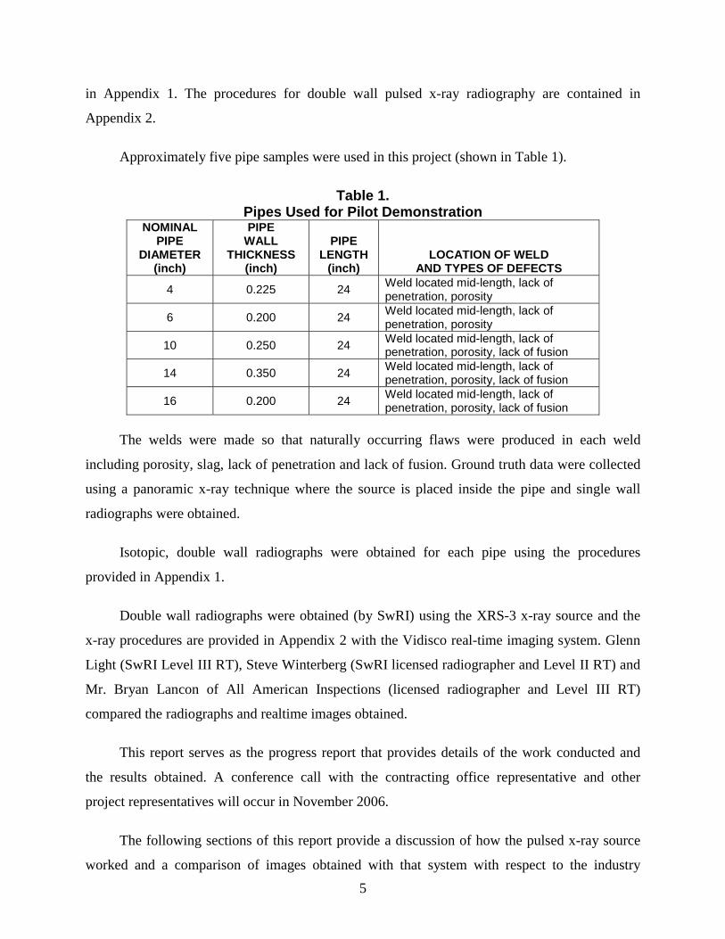
Approximately five pipe samples were used in this project (shown in Table 1).
Table 1. Pipes Used for Pilot Demonstration
NOMINAL PIPE
DIAMETER (inch)
PIPE WALL
THICKNESS (inch)
PIPE LENGTH
(inch) LOCATION OF WELD
AND TYPES OF DEFECTS
4 0.225 24 Weld located mid-length, lack of penetration, porosity
6 0.200 24 Weld located mid-length, lack of penetration, porosity
10 0.250 24 Weld located mid-length, lack of penetration, porosity, lack of fusion
14 0.350 24 Weld located mid-length, lack of penetration, porosity, lack of fusion
16 0.200 24 Weld located mid-length, lack of penetration, porosity, lack of fusion
The welds were made so that naturally occurring flaws were produced in each weld
including porosity, slag, lack of penetration and lack of fusion. Ground truth data were collected
using a panoramic x-ray technique where the source is placed inside the pipe and single wall
radiographs were obtained.
Isotopic, double wall radiographs were obtained for each pipe using the procedures
provided in Appendix 1.
Double wall radiographs were obtained (by SwRI) using the XRS-3 x-ray source and the
x-ray procedures are provided in Appendix 2 with the Vidisco real-time imaging system. Glenn
Light (SwRI Level III RT), Steve Winterberg (SwRI licensed radiographer and Level II RT) and
Mr. Bryan Lancon of All American Inspections (licensed radiographer and Level III RT)
compared the radiographs and realtime images obtained.
This report serves as the progress report that provides details of the work conducted and
the results obtained. A conference call with the contracting office representative and other
project representatives will occur in November 2006.
The following sections of this report provide a discussion of how the pulsed x-ray source
worked and a comparison of images obtained with that system with respect to the industry

6
standard (double wall isotopic) and the impressions of a vendor in the field of pipeline
inspection. Key issues discussed include time required to obtain the images, density of the
radiograph, detection of defects, and general image quality.
3.3 Discussion
The approach suggested by SwRI was to demonstrate the capabilities of a 270KVP pulsed,
battery powered x-ray unit and to compare the double wall pipe radiographs generated using the
pulsed x-ray source with the real-time imaging device to radiographs generated with Ir192 and
film. The demonstration application was double wall radiography (where the source is placed on
one side of the pipe and the film or imager is on the other side of the pipe) for a variety of pipe
welds (ranging in diameter from 4 to 16 inches) as illustrated in Figure 4. The pipes were
fabricated with intentionally placed defects. The welders intentionally used poor welding
techniques to generate regions of lack of fusion, lack of penetration, porosity, and slag. The
intent was to develop a number of regions where natural defects occurred as well as a number of
regions where there were few or no defects. Examples of the pipes and the types of defects are
illustrated in Figure 5.
Figure 4. Illustration of source size and film/detector set
used for the isotopic and pulsed x-ray sources

7
Figure 5. Photographs of portions of each pipe size showing some types of defects generated in the welds
Photographs showing how the single wall and double wall radiographs were obtained with
the isotopic source and the pulsed x-ray source are shown in Figures 6-8.
Figure 6. Photograph showing isotopic source being used to take single-wall radiographs

8
Figure 7. Photograph showing isotopic source used for double wall radiographs
Figure 8. Pulsed x-ray source with Vidisco real-time imaging used for double wall radiographs

9
Single wall isotopic radiographs were taken as a standard to verify defect detection. An
example of a single wall radiograph is shown in Figure 9. The report of defects detected in each
pipe weld is provided in Tables 2-1 to 2-5.
Figure 9. Single wall isotopic radiograph on 16-inch-diameter pipe
Table 2-1 Single Wall/Single View Isotopic Radiography Data
for 4-Inch-Diameter Pipe Weld
Defect Type Defect Location (Weld Center, Upstream
(US) side of weld or Downstream (DS) side of weld @ Designated inches)
Defect Size in Inches
Slag Center @ 0-1 0.13 Slag US @ 0-1 0.13 Slag DS @ 0-1 0.13 Lack of penetration (LOP) DS @ 0-1 0.13 LOP DS @ 1-2 0.60 LOP US @ 1-2 0.10 LOP US @ 1-2 0.10 Slag Center to US @ 3 0.13 Lack of fill US @ 4-5 0.38 LOP Center @ 6-11 4.00 LOP Center @ 11-0 1.50

10
Table 2-2 Single Wall/Single View Isotopic Radiography Data
for 6-Inch-Diameter Pipe Weld
Defect Type Defect Location (Weld Center, Upstream
(US) side of weld or Downstream (DS) side of weld @ Designated inches)
Defect Size in Inches
Lack of material DS @ 1-2 0.80 Lack of fusion at wall DS @ 1-2 0.25 Slag DS @ 2-3 0.13 Slag US @ 2-3 0.13 POR Center @ 2-3 0.08 LOP Center @ 2-3 0.25 Elongated porosity US @ 3-4 0.06 Slag DS @ 4-5 0.13 Lack of fill US to DS @ 5 0.25 Lack of fusion at wall DS @ 6-7 0.20 Crater crack US to DS @ 6-7 0.30 Porosity cluster US to DS @ 7 Total 0.3 Porosity cluster US to DS@ 8-9 Total 0.3 Porosity cluster Center@ 11-12 0.3 total LOP US to DS@ 12-13 0.50 LOP Center @ 12-13 0.30 Lack of fusion (LOF) Center @ 15-21 5.30 POR Center @ 17 0.25 Porosity cluster US to DS @ 19 0.40
Table 2-3 Single Wall/Single View Isotopic Radiography Data
for 10-Inch-Diameter Pipe Weld
Defect Type Defect Location (Weld Center, Upstream
(US) side of weld or Downstream (DS) side of weld @ Designated inches)
Defect Size in Inches
Scattered Porosity US - DS @ 0-4 Range: 0.04 -0.08 LOP Center @ 11-12 0.60 Porosity Center @ 11-12 0.08 Porosity cluster US - DS @ 14-15 0.50 Lack of fusion Center @ 15-17 1.30 Lack of fusion Center @ 17-21 3.40 Porosity cluster US - DS @ 22-23 0.75 Slag - 4 each US @ 23-24 Total 0.5 Lack of fill US @ 25-26 0.25 Scattered Porosity US - DS @ 26-29 Range: 0.04 -0.1

11
Table 2-4 Single Wall/Single View Isotopic Radiography Data
for 14-Inch-Diameter Pipe Weld
Defect Type Defect Location (Weld Center, Upstream
(US) side of weld or Downstream (DS) side of weld @ Designated inches)
Defect Size in Inches
LOP Center @ 43-1 2.00 LOP Center @ 1-3 1.90 LOP Center @ 12 0.13 Lack of fill - Intermittent US - DS @ 14-16 Total 1.0 Lack of fill US @ 14-17 0.60 Porosity cluster DS @ 17-18 0.50 Slag US @ 19-20 0.20 LOP Center @ 26 0.30 Scattered Porosity US @ 35-37 Range: 0.03-0.05 LOP US @ 26 0.30 Scattered Porosity US @ 35-37 Range: 0.03-0.05 LOP Center @ 37-39 2.00 Slag US @ 41-42 0.13 Porosity cluster US @ 43-0 0.60
Table 2-5 Single Wall/Single View Isotopic Radiography Data
for 16-Inch-Diameter Pipe Weld
Defect Type Defect Location (Weld Center, Upstream
(US) side of weld or Downstream (DS) side of weld @ Designated inches)
Defect Size in Inches
Porosity Cluster US - Center @ 0 0.60 Lack of Fusion Center @ 0-18 18.00 Scattered Porosity US - DS @ 7-11 Range: 0.03-0.08 Scattered Porosity US - DS @ 14-18 Range: 0.03-0.07 Porosity Center @ 21-22 0.10 Porosity Center @ 24 0.10 Scattered Porosity US - DS @ 26-34 Range: 0.03-0.14 Slag US @ 28-29 0.50 Porosity US @ 37 0.12 LOP Center @ 38-39 0.30 Porosity Cluster US - DS @ 41-42 0.75 Lack of fusion US @ 40-41 0.13 Lack of fusion US @ 41-42 0.50 Porosity cluster US - DS @ 49-50 0.75 LOP Center @ 48-49 0.20

12
The double wall isotopic radiographs were taken as a standard, normal field inspection
technique and the reports of defects found in the five pipe welds are given in Tables 3-1 to 3-5.
Table 3-1 Double Wall/Single View Isotopic Radiography Data
4-Inch-Diameter Pipe Weld
Defect Type Defect Location (Weld Center, Upstream
(US) side of weld or Downstream (DS) side of weld @ Designated inches)
Defect Size in Inches
Slag Center @ 0-1 0.13 Slag US @ 0-1 0.13 Slag DS @ 0-1 0.13 LOP DS @ 0-1 0.13 LOP Center @ 1-2 0.13 LOP Center @ 1-2 0.13 POR Center @ 1-2 0.08 Lack of fill US to DS @ 2-3 0.25 Lack of fill US @ 4-5 0.25 LOP Center@ 6-11 4.00 LOP Center@ 11-0 1.50 Lack of fill US to DS @ 10-11 0.40
Table 3-2 Double Wall/Single View Isotopic Radiography Data
6-Inch-Diameter Pipe Weld
Defect Type Defect Location (Weld Center, Upstream
(US) side of weld or Downstream (DS) side of weld @ Designated inches)
Defect Size in Inches
Slag US @ 2 1.25 Porosity Center @ 2 0.10 LOP Center @ 2-3 0.26 Slag US @ 3-4 0.07 Porosity Clusters - 3 each US - DS @ 7, 8-9 & 11-12 0.3 Each Porosity Center @ 12 0.08 LOP US - DS @ 12 0.50 LOP Center @ 12-13 0.25 Porosity - 2 each Center @ 14 & 15 .06 Each Lack of fill US - DS @ 14-15 0.60 Porosity Center @ 15 0.08 Lack of fusion Center @ 15-0 5.50

13
Table 3-3
Double Wall/Single View Isotopic Radiography Data 10-Inch-Diameter Pipe Weld:
Defect Type Defect Location (Weld Center, Upstream
(US) side of weld or Downstream (DS) side of weld @ Designated inches)
Defect Size in Inches
Scattered Porosity US - DS @ 0-4 Range: 0.04 -0.08 LOP Center @ 5-6 0.75 LOP Center @ 11-12 0.60 Porosity Center @ 11-12 0.08 Porosity cluster US - DS @ 14-15 0.50 Lack of fusion Center @ 15-17 1.30 Lack of fusion Center @ 17-21 3.40 Porosity cluster US - DS @ 22-23 0.75 Slag - 4 each US @ 23-24 Total 0.5 Lack of fill US @ 25-26 0.25 Scattered Porosity US - DS @ 26-29 Range: 0.04 -0.1
Table 3-4 Double Wall/Single View Isotopic Radiography Data
14-Inch-Diameter Pipe Weld
Defect Type Defect Location (Weld Center, Upstream
(US) side of weld or Downstream (DS) side of weld @ Designated inches)
Defect Size in Inches
LOP Center @ 43-1 2.00 LOP Center @ 1-3 1.90 LOP - 2 each Center @ 7 0.13 & 0.10 LOP Center @ 12 0.13 Lack of fill - intermittent US - DS @ 14-16 Total 1.0 Lack of fill US @ 14-17 0.60 Porosity cluster DS @ 17-18 0.50 Slag US @ 19-20 0.20 Lack of fusion Center @ 22 0.50 LOP Center @ 26 0.30 Scattered Porosity US @ 35-37 Range: 0.03-0.05 LOP US @ 26 0.30 Porosity Cluster US @ 28-29 0.40 LOP DS @ 35-37 1.00 Scattered Porosity US @ 35-37 Range: 0.03-0.05 LOP Center @ 37-39 2.00 Scattered Slag US @ 39-40 Total 0.75 Slag US @ 41-42 0.13 Lack of fusion - intermittent Center @ 41-43 Total 1.0 Porosity cluster US @ 43-0 0.60

14
Table 3-5
Double Wall/Single View Isotopic Radiography Data 16-Inch-Diameter Pipe Weld
Defect Type Defect Location (Weld Center, Upstream
(US) side of weld or Downstream (DS) side of weld @ Designated inches)
Defect Size in Inches
Porosity Cluster US - Center @ 0 0.60 Lack of Fusion Center @ 0-18 18.00 Scattered Porosity US - DS @ 7-11 Range: 0.03-0.08 Lack of fill - scattered US @ 13-15 Total 1.0 Scattered Porosity US - DS @ 14-18 Range: 0.03-0.07 Porosity Center @ 21-22 0.10 Porosity Center @ 24 0.10 Scattered Porosity US - DS @ 26-34 Range: 0.03-0.14 Scattered Slag US - Center @ 26-35 Total 1.5 Porosity US @ 37 0.12 LOP Center @ 38-39 0.30 Porosity Cluster US - DS @ 41-42 0.75 Lack of fusion US @ 40-41 0.13 Lack of fusion US @ 41-42 0.50 Porosity cluster US - DS @ 49-50 0.75 LOP Center @ 48-49 0.20
An example of the double wall isotopic radiograph is shown in Figure 10. Then, double
wall radiographs were taken using the pulsed 270KV XRS-3 source with a Vidisco real-time
imaging system. The image obtained using this approach is shown in Figure 11. The reports of
defects detected are given in Tables 4-1 to 4-5.
The inspection procedures used to produce the double wall, isotopic radiographs required
approximately 10 seconds exposure for each radiograph and 30 minutes for film development.
For the pulsed x-ray source, real-time imaging system, each image required approximately 2
seconds of exposure and the image was observed in about 10 seconds. Looking at the images
shown in Figures 9, 10, and 11, it is obvious that the pulsed x-ray source, real-time imaging
images are very similar in sharpness and clarity to the isotopic radiography.

15
Figure 10. Double wall isotopic radiograph on 16-inch-diameter pipe
Figure 11. Composite real-time images obtained using the
XRS-3 pulsed x-ray source and the Vidisco imaging system

16
Table 4-1
Double Wall/Double View Digital Radiography Data 4-Inch-Diameter Pipe Weld
Defect Type Defect Location (Weld Center, Upstream
(US) side of weld or Downstream (DS) side of weld @ Designated inches)
Defect Size in Inches
Slag Center @ 0-1 0.30 Slag US @ 0-1 0.13 Slag DS @ 0-1 0.13 Lack of penetration (LOP) Center @ 1-2 0.10 Porosity cluster Center @ 3 Total 0.3 LOP Center @ 4 0.25 LOP Center @ 6 0.25 Lack of Fusion (LOF) Center @ 7-10 3.00 Lack of Fusion (LOF) Center @ 11-12 1.20
Table 4-2 Double Wall/Double View Digital Radiography Data
6-Inch-Diameter Pipe Weld
Defect Type Defect Location (Weld Center, Upstream
(US) side of weld or Downstream (DS) side of weld @ Designated inches)
Defect Size in Inches
Slag US @ 1-2 0.25 Slag Center @ 2 0.14 Slag US @ 2 0.14 Porosity DS @ 2-3 0.12 Lack of fill - 2 each DS @ 3-4 0.25 & 0.14 Porosity US @ 5-6 0.10 Porosity Cluster DS @ 7 Total 0.3 LOF US @ 7-9 2.00 Porosity cluster US - DS @ 11-12 Total 0.3 Slag US @ 12 0.15 LOP Center @ 12-13 0.15 Slag US @ 13 0.27 Porosity Center @ 13 0.13 Porosity US @ 13-14 0.11 LOF Center @ 15-0 4.50 Porosity cluster DS - Center @ 19 0.40

17
Table 4-3
Double Wall/Double View Digital Radiography Data 10-Inch-Diameter Pipe Weld
Defect Type Defect Location (Weld Center, Upstream
(US) side of weld or Downstream (DS) side of weld @ Designated inches)
Defect Size in Inches
Scattered Porosity US - DS @ 0-3 Average size 0.08 Porosity US @ 4-5 0.15 LOP DS @ 3-9 5.00 Porosity - 3 each US @ 7-8 Average size 0.15 Porosity - 3 each US @ 8-9 Average size 0.10 LOP DS @ 11-12 0.60 LOP DS @ 16-20 4.00 Scattered Porosity US - DS @ 15-20 Average size 0.10 Porosity cluster DS - Center @ 22-23 Total 0.70 Scattered Porosity US - DS @ 26-29 Average size 0.08 Porosity US @ 29-30 0.10 Slag US @ 29-31 0.80
Table 4-4
Double Wall/Single View Digital Radiography Data 14-Inch-Diameter Pipe Weld
Defect Type Defect Location (Weld Center, Upstream (US) side
of weld or Downstream (DS) side of weld @ Designated inches)
Defect Size
in Inches
Slag US @ 0 0.27 LOP Center @ 0-1 0.40 Porosity Center @ 1 0.10 LOP Center @ 1-2 0.25 LOP Center @ 1-2 0.27 LOP Center @ 2 0.15 LOP Center @ 2-4 1.10 LOP DS @ 7-8 0.25 LOP Center @ 7-11 3.40 Lack of fill Center @ 12-13 0.25 Slag DS @ 14-15 0.40 Scattered Slag US @ 14-18 Total 3.45 Porosity Cluster DS @ 17-18 Total 0.3 Slag US @ 19-20 0.24 LOP US - DS @ 22 0.40 Crater Crack DS @ 23-24 0.20 Slag, 2 each US @ 23-24 0.4 Each Lack of fill US - DS @ 25-26, 27-28, 29-30, 31-33, 33-34 & 40-41 Total 4.22 Porosity Cluster US @ 28-29 Total 0.3 LOP Center @ 39-43 2.70 Porosity US @ 41-42 0.13 Lack of fusion Center @ 43-1 1.60

18
Table 4-5 Double Wall/Single View Digital Radiography Data
16-Inch-Diameter Pipe Weld
Defect Type Defect Location (Weld Center, Upstream
(US) side of weld or Downstream (DS) side of weld @ Designated inches)
Defect Size in Inches
Lack of fusion Center @ 0-11 11.00 Porosity - 4 each Center @ 0 .05 each Porosity Cluster US - DS @ 6 Total 0.5 Scattered Porosity Center @ 7-11 .03 to 0.7 Lack of fill US - DS @ 7-8 0.70 Lack of fusion Center 11-12 0.70 Porosity Cluster US - DS @ 13 Total 0.4 Lack of fusion Center @ 13-15 0.75 Scattered Porosity US - DS @ 14-17 .03 to 0.8 Lack of fusion Center @ 17-18 0.60 Porosity DS @ 21-22 0.11 Porosity Center @ 24 0.10 Slag US @ 25-28 0.75 Porosity Center @ 27 0.10 Scattered Porosity US-DS @ 28-33 .03 to .08 Slag US-DS @ 34-35 Total 0.4 Porosity Cluster US-DS @ 40-42 Total 0.4 LOP Center @ 41-42 0.43 Porosity DS @ 45 0.13 Slag DS @ 45-47 1.65 Porosity - 2 each DS & Center @ 47-48 .15 & .07 LOP Center @ 48-49 0.20
Most industrial radiographic testing requires an image quality indicator (IQI) in each
radiograph to assure radiographic quality. Notice that in Figures 9, 10, and 11, the IQI is
observed and in both isotopic radiographs, five wires can be seen. The diameters of the five
wires are 0.032 inch, 0.026 inch, 0.020 inch, 0.016 inch, and 0.013 inch, respectively. However,
when the film is actually viewed with a magnifying glass on a viewer, the sixth wire which is
0.010 inch in diameter can also be seen. This means that the film has the resolution to resolve a
defect that is 0.01 inch in diameter.
In Figure 11, the same five wires can also be seen. However, by enhancing the digital
images to brighten or darken or increase or decrease contrast, the image can be sufficiently
changed so that the sixth wire is also easy to detect as illustrated in Figure 12. Magnification can
also help, but the pixel size becomes an issue. The pixel size is certainly larger than the film
grain, so inherently, the film has better optical resolution. However, the real-time imager may
have sufficient resolution for pipeline weld inspection.

19
Figure 12. Digital image on pipe showing six detectable wires on the IQI
A comparison of defects detected for the isotopic source/film radiographs and the pulsed x-
ray/digital radiographs are displayed on pseudo weld plans for 4-, 6-, and 10-inch-diameter pipe
are shown in Figures 13, 14, and 15, respectively. Similar data were obtained for the 14- and 16-
inch-diameter pipe welds. There are small differences between the defects detected and the size
of the recorded defects, but these differences are minor.
Figure 13. Illustration of defects reported in the 4-inch-diameter pipe weld
for both isotopic and pulsed x-ray radiography

20
Figure 14. Illustration of defects reported in the 6-inch-diameter pipe weld
for both isotopic and pulsed x-ray radiography
Figure 15. Illustration of defects reported in the 10-inch-diameter pipe weld
for both isotopic and pulsed x-ray radiography

21
3.4 Impact to End-Users
Issues to be addressed included differences in the procedures in terms of time, set up,
personnel required, source cost and labor/cost associated with following regulations, ease of use,
and a discussion of the likelihood of successfully transferring this technology to industry.
In terms of information obtained from the isotopic radiograph and the pulsed x-ray source
used in conjunction with the Vidisco real-time imaging system for this pipe diameter and
thickness range, the two were basically identical. In terms of procedure development, the pulsed
x-ray/Vidisco procedure development was faster because images could be obtained within a few
minutes of the actual exposure as compared to at least 30 minutes needed for film development
time to develop the isotopic procedure. In terms of geometrical issues, the vendor still preferred
the isotopic source because it is very small and can be taped directly onto the pipe (as illustrated
in Figure 16).
Figure 16. Photograph of isotopic source on pipe during radiography
In terms of actual radiation exposure time, for the isotopic source (depending on wall thickness)
the exposure time was on the order of 60 seconds per shot and for the pulsed x-ray source, the
exposure time for the same weld was approximately 3 seconds. Labor cost using the isotopic
source is approximately double the cost associated with using the pulsed x-ray source because
regulations require that two radiographers must be present when using an isotopic source while
only one radiographer is required when using an x-ray machine. In terms of ease of use, the
pulsed x-ray source/real-time imager is very similar to the isotopic source radiography. In terms
22
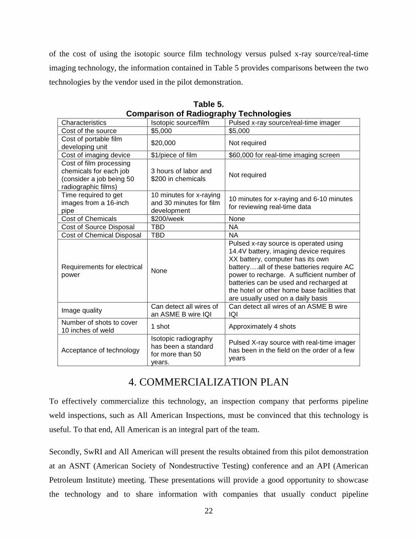
of the cost of using the isotopic source film technology versus pulsed x-ray source/real-time
imaging technology, the information contained in Table 5 provides comparisons between the two
technologies by the vendor used in the pilot demonstration.
Table 5. Comparison of Radiography Technologies
Characteristics Isotopic source/film Pulsed x-ray source/real-time imager Cost of the source $5,000 $5,000 Cost of portable film developing unit
$20,000 Not required
Cost of imaging device $1/piece of film $60,000 for real-time imaging screen Cost of film processing chemicals for each job (consider a job being 50 radiographic films)
3 hours of labor and $200 in chemicals
Not required
Time required to get images from a 16-inch pipe
10 minutes for x-raying and 30 minutes for film development
10 minutes for x-raying and 6-10 minutes for reviewing real-time data
Cost of Chemicals $200/week None Cost of Source Disposal TBD NA Cost of Chemical Disposal TBD NA
Requirements for electrical power
None
Pulsed x-ray source is operated using 14.4V battery, imaging device requires XX battery, computer has its own battery….all of these batteries require AC power to recharge. A sufficient number of batteries can be used and recharged at the hotel or other home base facilities that are usually used on a daily basis
Image quality Can detect all wires of an ASME B wire IQI
Can detect all wires of an ASME B wire IQI
Number of shots to cover 10 inches of weld
1 shot Approximately 4 shots
Acceptance of technology
Isotopic radiography has been a standard for more than 50 years.
Pulsed X-ray source with real-time imager has been in the field on the order of a few years
4. COMMERCIALIZATION PLAN
To effectively commercialize this technology, an inspection company that performs pipeline
weld inspections, such as All American Inspections, must be convinced that this technology is
useful. To that end, All American is an integral part of the team.
Secondly, SwRI and All American will present the results obtained from this pilot demonstration
at an ASNT (American Society of Nondestructive Testing) conference and an API (American
Petroleum Institute) meeting. These presentations will provide a good opportunity to showcase
the technology and to share information with companies that usually conduct pipeline
23
inspections using isotopic sources. These presentations will most likely occur at the 2007 ASNT
Fall Conference and the 2007 API Conference.
Aerospace application involved in the maintenance and repair of aerospace structures could be a
viable commercial area. Perhaps evaluating the system at the FAA NDI validation center would
provide some credibility to the system and its capabilities.
As a provider of services, All American would be able to market the system easily. Durability of
the system and duty cycle would need to be evaluated, but the potential is there.
5. CONCLUSIONS
Based upon the work conducted to date on this project, the following conclusions have been
reached.
(1) For double wall pipe radiography (which is the requirement for field pipeline weld joint
inspection), isotopic radiography and pulsed x-ray with real-time imaging capability
provide results that meet the code requirements. The nominal code requires that ASME IQI
B wire (all wires) can be detected.
(2) This system is excellent for the intended DOT pipeline inspection, providing the adequate
sensitivities are achieved. Because of its portability and reduced exposure time this seems
to be a “great fit”.
(3) Contacting ASTM and approaching their radiographic committee in an effort to address
this type of system specifically would be a vehicle to encourage its use industry wide.

APPENDIX 1
X-ray Radiographic Procedures for Isotopic Double Wall Radiography

Isotopic Radiography Report for 3.5” diameter, 0.225” wall SOURCE
Radiation Type: X-Ray Gamma Ray Method: Internal External Manufacturer: Amersham Ir192
MA: N/A KV: N/A Curies: 44 Focal Spot Size: .130"
INTENSIFICATION SCREENS
Type: LEAD Thickness (Front): .010 In. (Back): .010 In.
GEOMETRIC ARRANGEMENT
Viewing: SWE/SWV DWE/DWV DWE/SWV Source to Film Distance: 4 in. Object to Film Distance: ..375 in. Source Position: Offset 0 in. Offset Angle: 0°
FILM DATA
No. Exp: 3 (per item) Film Size: 4.5 In. Wide X 10 In. length Diagnostic Readable Length: 3.66 In. Film Overlap: 3.00 In. Film Type: D4 Class: 1 Manufacturer: Agfa No. Film in Cassette: 1 Unexposed Base Density: .02 Cassette Separation 120 Deg Exposed density of: Parental Material: Weld Metal: 2.5 Equipment Used To Determine Density: McBETH TD-52 Method: Multiple Film Single Film Film Position: 120 DEG.
FILM PROCESSING
Drying Detail: FORCED AIR Manual / Automatic Developing Time: 5.5 MIN Manufacture: Agfa Rinse Time: .5 MIN Manufacture Agfa Fix Time: 4 MIN Manufacture: Agfa Final Rinse: 10 MIN Temp: 68°
EXPOSURE TIMES
Single Exposure: 12 Sec Total Exposure Time: 36 SEC Curie Seconds: 528
PENETRAMETER
Penetrameter Material SS I.D. No. ASTM B Shim Thickness: N/A Type: Wire Film Side: Source Side: Penetrameter Position: IN WELD No. per Film: 1 Sensitivity Required: 2T
LETTER/NO. BELT
Orientation of Markers PARALLEL TO WELD Manner of Location 1" incriments
MATERIAL DATA Diameter: 3.5 in. W.T. .225 in. Grade Material: Joint Design: BUTT
WELDING PROCESS SMAW GMAW Automatic Other: GTAW
Remarks:
Prepared By: Carl Martinez Approved By: B. Lancon

Isotopic Radiography Report for 6” diameter, 0.20” wall
SOURCE
Radiation Type: X-Ray Gamma Ray Method: Internal External Manufacturer: Amersham Ir192
MA: N/A KV: N/A Curies: 44 Focal Spot Size: .130"
INTENSIFICATION SCREENS
Type: LEAD Thickness (Front): .010 In. (Back): .010 In.
GEOMETRIC ARRANGEMENT
Viewing: SWE/SWV DWE/DWV DWE/SWV Source to Film Distance: 6.00 in. Object to Film Distance: ..325 in. Source Position: Offset 0 in. Offset Angle: 0°
FILM DATA
No. Exp: 3 (per item) Film Size: 4.5 In. Wide X 10 In. length Diagnostic Readable Length: 6.28 In. Film Overlap: 1.86 In. Film Type: D4 Class: 1 Manufacturer: Agfa No. Film in Cassette: 1 Unexposed Base Density: .02 Cassette Separation 120 Deg Exposed density of: Parental Material: Weld Metal: 2.4-2.5 Equipment Used To Determine Density: McBETH TD-52 Method: Multiple Film Single Film Film Position: 120 DEG.
FILM PROCESSING
Drying Detail: FORCED AIR Manual / Automatic Developing Time: 5 MIN Manufacture: Agfa Rinse Time: .5 MIN Manufacture Agfa Fix Time: 4 MIN Manufacture: Agfa Final Rinse: 10 MIN Temp: 68°
EXPOSURE TIMES
Single Exposure: 30 Sec Total Exposure Time: 90 SEC Curie Seconds: 1320
PENETRAMETER
Penetrameter Material SS I.D. No. ASTM B Shim Thickness: N/A Type: Wire Film Side: Source Side: Penetrameter Position: IN WELD No. per Film: 1 Sensitivity Required: 2T
LETTER/NO. BELT
Orientation of Markers PARALLEL TO WELD Manner of Location 1" incriments
MATERIAL DATA Diameter: 6.0 in. W.T. .200 in. Grade Material: Joint Design: BUTT
WELDING PROCESS SMAW GMAW Automatic Other: GTAW
Remarks:
Prepared By: Carl Martinez Approved By: B. Lancon

Isotopic Radiography Report for 10” diameter, 0.25” wall SOURCE
Radiation Type: X-Ray Gamma Ray Method: Internal External Manufacturer: Amersham Ir192
MA: N/A KV: N/A Curies: 100 Focal Spot Size: .160"
INTENSIFICATION SCREENS
Type: LEAD Thickness (Front): .010 In. (Back): .010 In.
GEOMETRIC ARRANGEMENT
Viewing: SWE/SWV DWE/DWV DWE/SWV Source to Film Distance: 10.00 in. Object to Film Distance: .375 in. Source Position: Offset 0 in. Offset Angle: 0°
FILM DATA
No. Exp: 3 (per item) Film Size: 4.5 In. Wide X 17 In. length Diagnostic Readable Length: 10.46 In. Film Overlap: 3.26 In. Film Type: D4 Class: 1 Manufacturer: Agfa No. Film in Cassette: 1 Unexposed Base Density: .02 Cassette Separation 120 Deg Exposed density of: Parental Material: Weld Metal: 2.5-3.0 Equipment Used To Determine Density: McBETH TD-52 Method: Multiple Film Single Film Film Position: 120 DEG.
FILM PROCESSING
Drying Detail: FORCED AIR Manual / Automatic Developing Time: 5 MIN Manufacture: Agfa Rinse Time: .5 MIN Manufacture Agfa Fix Time: 4 MIN Manufacture: Agfa Final Rinse: 10 MIN Temp: 68°
EXPOSURE TIMES
Single Exposure: 40 Sec Total Exposure Time: 120 SEC Curie Seconds: 400
PENETRAMETER
Penetrameter Material SS I.D. No. ASTM B Shim Thickness: N/A Type: Wire Film Side: Source Side: Penetrameter Position: IN WELD No. per Film: 1 Sensitivity Required: 2T
LETTER/NO. BELT
Orientation of Markers PARALLEL TO WELD Manner of Location 1" incriments
MATERIAL DATA Diameter: 10.0 in. W.T. .250 in. Grade Material: Joint Design: BUTT
WELDING PROCESS SMAW GMAW Automatic Other: GTAW
Remarks:
Prepared By: Carl Martinez Approved By: B. Lancon

Isotopic Radiography Report for 14” diameter, 0.35” wall SOURCE
Radiation Type: X-Ray Gamma Ray Method: Internal External Manufacturer: Amersham Ir192
MA: N/A KV: N/A Curies: 100 Focal Spot Size: .160"
INTENSIFICATION SCREENS
Type: LEAD Thickness (Front): .010 In. (Back): .010 In.
GEOMETRIC ARRANGEMENT
Viewing: SWE/SWV DWE/DWV DWE/SWV Source to Film Distance: 14.00 in. Object to Film Distance: .425 in. Source Position: Offset 0 in. Offset Angle: 0°
FILM DATA
No. Exp: 3 (per item) Film Size: 4.5 In. Wide X 17 In. length Diagnostic Readable Length: 14.65 In. Film Overlap: 1.17 In. Film Type: D4 Class: 1 Manufacturer: Agfa No. Film in Cassette: 1 Unexposed Base Density: .02 Cassette Separation 120 Deg Exposed density of: Parental Material: Weld Metal: 2.5-3.0 Equipment Used To Determine Density: McBETH TD-52 Method: Multiple Film Single Film Film Position: 120 DEG.
FILM PROCESSING
Drying Detail: FORCED AIR Manual / Automatic Developing Time: 5 MIN Manufacture: Agfa Rinse Time: .5 MIN Manufacture Agfa Fix Time: 4 MIN Manufacture: Agfa Final Rinse: 10 MIN Temp: 68°
EXPOSURE TIMES
Single Exposure: 80 Sec Total Exposure Time: 240 SEC Curie Seconds: 800
PENETRAMETER
Penetrameter Material SS I.D. No. ASTM B Shim Thickness: N/A Type: Wire Film Side: Source Side: Penetrameter Position: IN WELD No. per Film: 1 Sensitivity Required: 2T
LETTER/NO. BELT
Orientation of Markers PARALLEL TO WELD Manner of Location 1" incriments
MATERIAL DATA Diameter: 14.0 in. W.T. .350 in. Grade Material: Joint Design: BUTT
WELDING PROCESS SMAW GMAW Automatic Other: GTAW
Remarks:
Prepared By: Carl Martinez Approved By: B. Lancon

Isotopic Radiography Report for 16” diameter, 0.20” wall SOURCE
Radiation Type: X-Ray Gamma Ray Method: Internal External Manufacturer: Amersham Ir192
MA: N/A KV: N/A Curies: 100 Focal Spot Size: .160"
INTENSIFICATION SCREENS
Type: LEAD Thickness (Front): .010 In. (Back): .010 In.
GEOMETRIC ARRANGEMENT
Viewing: SWE/SWV DWE/DWV DWE/SWV Source to Film Distance: 16.00 in. Object to Film Distance: .325 in. Source Position: Offset 0 in. Offset Angle: 0°
FILM DATA
No. Exp: 4 (per item) Film Size: 4.5 In. Wide X 17 In. length Diagnostic Readable Length: 12.56 In. Film Overlap: 2.22 In. Film Type: D4 Class: 1 Manufacturer: Agfa No. Film in Cassette: 1 Unexposed Base Density: .02 Cassette Separation 120 Deg Exposed density of: Parental Material: Weld Metal: 2.5-2.7 Equipment Used To Determine Density: McBETH TD-52 Method: Multiple Film Single Film Film Position: 120 DEG.
FILM PROCESSING
Drying Detail: FORCED AIR Manual / Automatic Developing Time: 5 MIN Manufacture: Agfa Rinse Time: .5 MIN Manufacture Agfa Fix Time: 4 MIN Manufacture: Agfa Final Rinse: 10 MIN Temp: 68°
EXPOSURE TIMES
Single Exposure: 70 Sec Total Exposure Time: 280 SEC Curie Seconds: 700
PENETRAMETER
Penetrameter Material SS I.D. No. ASTM B Shim Thickness: N/A Type: Wire Film Side: Source Side: Penetrameter Position: IN WELD No. per Film: 1 Sensitivity Required: 2T
LETTER/NO. BELT
Orientation of Markers PARALLEL TO WELD Manner of Location 1" incriments
MATERIAL DATA Diameter: 16.0 in. W.T. .200 in. Grade Material: Joint Design: BUTT
WELDING PROCESS SMAW GMAW Automatic Other: GTAW
Remarks:
Prepared By: Carl Martinez Approved By: B. Lancon

APPENDIX 2
X-ray Radiographic Procedures for Pulsed X-ray Double Wall Radiography

S O U T H W E S T R E S E A R C H I N S T I T U T E®
6220 CULEBRA ROAD • POST OFFICE DRAWER 28510 • SAN ANTONIO, TEXAS, USA 78228-0510 • (210) 684-5111 • WWW.SWRI.ORG
APPLIED PHYSICS DIVISION • FAX: (210) 684-4822
Pulsed X-ray Radiography Report for 3.5” diameter, 0.225” wall
SOURCE
Radiation Type: Pulsed X-Ray Method: Internal External Manufacturer: Golden XRS-3
MA: N/A KV: N/A Curies:NA 4 mR/pulse @ 12” from Source
Focal Spot Size: 0.125”
REAL TIME IMAGING PLATE
Vidisco
INTENSIFICATION SCREENS
Type: NA Thickness (Front): NA In. (Back): NA In.
GEOMETRIC ARRANGEMENT
Viewing: SWE/SWV DWE/DWV DWE/SWV Source to Film Distance: 4 in. Object to Film Distance: ..375 in. Source Position: Offset 0 in. Offset Angle: 0°
FILM DATA
NA
FILM PROCESSING
NA
EXPOSURE TIMES
Single Exposure: approximately 2 sec
PENETRAMETER
Penetrameter Material SS I.D. No. ASTM B Shim Thickness: N/A Type: Wire Film Side: Source Side: Penetrameter Position: IN WELD No. per Film: 1 Sensitivity Required: 2T
LETTER/NO. BELT
Orientation of Markers PARALLEL TO WELD Manner of Location 1" incriments
MATERIAL DATA Diameter: 3.5 in. W.T. .225 in. Grade Material: Joint Design: BUTT
WELDING PROCESS SMAW GMAW Automatic Other: GTAW
Remarks:
Prepared By: Steve Winterberg Approved By: G. Light

S O U T H W E S T R E S E A R C H I N S T I T U T E®
6220 CULEBRA ROAD • POST OFFICE DRAWER 28510 • SAN ANTONIO, TEXAS, USA 78228-0510 • (210) 684-5111 • WWW.SWRI.ORG
APPLIED PHYSICS DIVISION • FAX: (210) 684-4822
Pulsed X-ray Radiography Report for 6” diameter, 0.20” wall
SOURCE
Radiation Type: Pulsed X-Ray Method: Internal External Manufacturer: Golden XRS-3
MA: N/A KV: N/A Curies:NA 4 mR/pulse @ 12” from Source
Focal Spot Size: 0.125”
REAL TIME IMAGING PLATE
Vidisco
INTENSIFICATION SCREENS
Type: NA Thickness (Front): NA In. (Back): NA In.
GEOMETRIC ARRANGEMENT
Viewing: SWE/SWV DWE/DWV DWE/SWV Source to Film Distance: 4 in. Object to Film Distance: ..375 in. Source Position: Offset 0 in. Offset Angle: 0°
FILM DATA
NA
FILM PROCESSING
NA
EXPOSURE TIMES
Single Exposure: approximately 2 sec
PENETRAMETER
Penetrameter Material SS I.D. No. ASTM B Shim Thickness: N/A Type: Wire Film Side: Source Side: Penetrameter Position: IN WELD No. per Film: 1 Sensitivity Required: 2T
MATERIAL DATA Diameter: 6.0 in. W.T. .200 in. Grade Material: Joint Design: BUTT
WELDING PROCESS SMAW GMAW Automatic Other: GTAW
Remarks:
Prepared By: Steve Winterberg Approved By: G.Light

S O U T H W E S T R E S E A R C H I N S T I T U T E®
6220 CULEBRA ROAD • POST OFFICE DRAWER 28510 • SAN ANTONIO, TEXAS, USA 78228-0510 • (210) 684-5111 • WWW.SWRI.ORG
APPLIED PHYSICS DIVISION • FAX: (210) 684-4822
Pulsed X-ray Radiography Report for 10” diameter, 0.25” wall
SOURCE
Radiation Type: Pulsed X-Ray Method: Internal External Manufacturer: Golden XRS-3
MA: N/A KV: N/A Curies:NA 4 mR/pulse @ 12” from Source
Focal Spot Size: 0.125”
REAL TIME IMAGING PLATE
Vidisco
INTENSIFICATION SCREENS
Type: NA Thickness (Front): NA In. (Back): NA In.
GEOMETRIC ARRANGEMENT
Viewing: SWE/SWV DWE/DWV DWE/SWV Source to Film Distance: 4 in. Object to Film Distance: ..375 in. Source Position: Offset 0 in. Offset Angle: 0°
FILM DATA
NA
FILM PROCESSING
NA
EXPOSURE TIMES
Single Exposure: approximately 2 sec
PENETRAMETER
Penetrameter Material SS I.D. No. ASTM B Shim Thickness: N/A Type: Wire Film Side: Source Side: Penetrameter Position: IN WELD No. per Film: 1 Sensitivity Required: 2T
MATERIAL DATA Diameter: 10.0 in. W.T. .250 in. Grade Material: Joint Design: BUTT
WELDING PROCESS SMAW GMAW Automatic Other: GTAW
Remarks:
Prepared By: Steve Winterberg Approved By: G. Light

S O U T H W E S T R E S E A R C H I N S T I T U T E®
6220 CULEBRA ROAD • POST OFFICE DRAWER 28510 • SAN ANTONIO, TEXAS, USA 78228-0510 • (210) 684-5111 • WWW.SWRI.ORG
APPLIED PHYSICS DIVISION • FAX: (210) 684-4822
Pulsed X-ray Radiography Report for 14” diameter, 0.35” wall
SOURCE
Radiation Type: Pulsed X-Ray Method: Internal External Manufacturer: Golden XRS-3
MA: N/A KV: N/A Curies:NA 4 mR/pulse @ 12” from Source
Focal Spot Size: 0.125”
REAL TIME IMAGING PLATE
Vidisco
INTENSIFICATION SCREENS
Type: NA Thickness (Front): NA In. (Back): NA In.
GEOMETRIC ARRANGEMENT
Viewing: SWE/SWV DWE/DWV DWE/SWV Source to Film Distance: 4 in. Object to Film Distance: ..375 in. Source Position: Offset 0 in. Offset Angle: 0°
FILM DATA
NA
FILM PROCESSING
NA
EXPOSURE TIMES
Single Exposure: approximately 2 sec
PENETRAMETER
Penetrameter Material SS I.D. No. ASTM B Shim Thickness: N/A Type: Wire Film Side: Source Side: Penetrameter Position: IN WELD No. per Film: 1 Sensitivity Required: 2T
MATERIAL DATA Diameter: 14.0 in. W.T. .350 in. Grade Material: Joint Design: BUTT
WELDING PROCESS SMAW GMAW Automatic Other: GTAW
Remarks:
Prepared By: Steve Winterberg Approved By: G. Light

S O U T H W E S T R E S E A R C H I N S T I T U T E®
6220 CULEBRA ROAD • POST OFFICE DRAWER 28510 • SAN ANTONIO, TEXAS, USA 78228-0510 • (210) 684-5111 • WWW.SWRI.ORG
APPLIED PHYSICS DIVISION • FAX: (210) 684-4822
Pulsed X-ray Radiography Report for 16” diameter, 0.20” wall
SOURCE
Radiation Type: Pulsed X-Ray Method: Internal External Manufacturer: Golden XRS-3
MA: N/A KV: N/A Curies:NA 4 mR/pulse @ 12” from Source
Focal Spot Size: 0.125”
REAL TIME IMAGING PLATE
Vidisco
INTENSIFICATION SCREENS
Type: NA Thickness (Front): NA In. (Back): NA In.
GEOMETRIC ARRANGEMENT
Viewing: SWE/SWV DWE/DWV DWE/SWV Source to Film Distance: 4 in. Object to Film Distance: ..375 in. Source Position: Offset 0 in. Offset Angle: 0°
FILM DATA
NA
FILM PROCESSING
NA
EXPOSURE TIMES
Single Exposure: approximately 2 sec
PENETRAMETER
Penetrameter Material SS I.D. No. ASTM B Shim Thickness: N/A Type: Wire Film Side: Source Side: Penetrameter Position: IN WELD No. per Film: 1 Sensitivity Required: 2T
MATERIAL DATA Diameter: 16.0 in. W.T. .200 in. Grade Material: Joint Design: BUTT
WELDING PROCESS SMAW GMAW Automatic Other: GTAW
Remarks:
Prepared By: Steve Winterberg Approved By: G. Light