pulsed plasma thrusters for small spacecraft attitude · pdf filepulsed plasma thrusters for...
TRANSCRIPT

NASA Contractor Report 198517
Pulsed Plasma Thrusters for Small
Spacecraft Attitude Control
Melissa L. McGuire
Analex CorporationBrook Park, Ohio
and
Roger M. MyersNYMA, Inc.
Brook Park, Ohio
August 1996
Prepared forLewis Research Center
Under Contracts NAS3-27600 and NAS3-27186
National Aeronautics and
Space Administration

PULSED PLASMA THRUSTERS FOR SMALL SPACECRAFT ATTITUDE CONTROL
Melissa L. McGuire
Analex CorporationNASA Lewis Research Center
Cleveland, Ohio 44135
Roger M. MyersNYMA Inc.
NASA Lewis Research Center
Cleveland, Ohio 44 135
ABSTRACT
Pulsed Plasma Thrusters (PPTs) are a new option for attitude control of a small spacecraft and may result in reduced
attitude control system (ACS) mass and cost. The primary purpose of an ACS is to orient the spacecraft to the
desired accuracy in inertial space. The ACS functions for which the PPT system will be analyzed include disturbance
torque compensation, and slewing maneuvers such as sun acquisition for which the small impulse bit and high
specific impulse of the PPT offers unique advantages. The NASA Lewis Research Center (LeRC) currently has acontracted flight PPT system development program in place with Olin Aerospace with a delivery date of October
1997. The PPT systems in this study are based upon the work being done under the NASA LeRC program.
Analysis of the use of PPTs for ACS showed that the replacement of the standard momentum wheels and torque rods
with a PPT system to perform the attitude control maneuvers on a small low Earth orbiting spacecraft reduced theACS mass by 50 to 75% with no increase in required power level over comparable wheel-based systems, though
rapid slewing power requirements may present an issue.
1. INTRODUCTION
In this age of shrinking spacecraft size and smallerlaunch vehicle capacity, there is a greater need to fit
more payload for more science return on a given
spacecraft. For a given launch vehicle, increasing the
payload mass requires a reduction of the mass andvolume of the other spacecraft subsystems. Mass,
volume, system comPlexity, reliability, and cost arecritical areas in the design of a small spacecraft. Any
additional subsystem increases spacecraft complexityand mass. In order to decrease spacecraft bus size or to
increase the payload for a given bus, the core systemsneed to be made smaller and lighter. This paper
presents a new option for ACS which may achieve
these goals.
This study is a feasibility analysis of a Pulsed Plasma
Thruster (PPT) system to perform disturbance torque
compensation and deadband control for a small
spacecraft in low earth orbit (LEO). Pulsed plasmathrusters accelerate small quantities of ablated
fluorocarbon propellant to generate very small impulse
bits (100 to 1000 I.tNs) at high specific impulse (-1000
s).l These characteristics make PPTs an attractive
option for ACS functions. State-of-the-art attitude
control systems consist of hardware such as momentumwheels, magnetic torque rods, and/or thrusters, typically
hydrazine (N2I-I4), used to stabilize the spacecraft against
disturbance torques resulting from either environment or
spacecraft operation. The capabilities of PPTs will beexamined to perform the total ACS functions in this
study. Since momentum wheels are well known and
trusted, replacement of the magnetic torque rods orthrusters in dumping the momentum wheels, or
replacement of two of the three momentum wheels usedin 3-axis stabilization are also viable options for the useof PPTs and will be left as topics of further studies.
Section two of this paper will present a background of
attitude control functions as well as a baseline of current

ACS. Sectionthreeoffersadescriptionof PPTswithinformationaboutpresentandfuturegroundtestdemonstrationsandbriefhistoryof thePPTprogram.Withthismaterial,theanalysisinsectionfourpresentsthe resultsof using PPTsto performboth themomentumcompensationin placeof wheelsandslewingmaneuvers.Finally,sectionfivesummarizestheconclusionsofthispreliminaryfeasibilityanalysis.
2.ATTITUDECONTROLSYSTEMS
Theattitudecontrolsystemofaspacecraftstabilizesandorientsit in thedesireddirectionandto thedesiredfidelityasdictatedbythemission.Disturbanceswhichthreatento corrupt this attitudearise from theenvironmentaroundthespacecraft(gravity-gradient,solar pressure,magneticfield interactions,andatmosphericdrag)aswellasfromthespacecraftitself(propellantsloshing,thrustermisalignment,andoffsetsbetweenthecenterof gravityandcenterof pressure).2Thewheelscountertheangularmomentuminducedbythesetorquesthroughspinning,whilethrustersarefiredtobalancetheexternaltorques.2
A typicalACSin usetodayconsistsof fourwheels(threeprimaryandonebackuptocoverthreeaxes),anelectronicsunit,andawheeldesaturationsystem.Thelattercanbeeithermagnetictorquerodswhichuseanelectriccurrentto producea magneticfield whichinteractswith theearth'smagneticfieldto produceatorque,orhydrazinethrusterswhichproduceaforcethatactsonamomen_armonthespacecraftalsotoproduceatorque.Fourwheel,three-axissystemsforattitudecontrolcanbemassiveandhighvolume,andhavesufferedfromreliabilityproblems.Asoneexample,theESA(EuropeanSpaceAgency)spacecraftSOHO(SolarandHeliosphericObservatory)experienceddifficultieswith its momentumwheelswhichthreatenedtheimpendinglaunchdate.Thewheelshadtobereplacedcompletely.3
Twoexamples of current small spacecraft and their ACShardware are the TOMS-EP (Total Ozone Mapping
Spectrometer - Earth Probe), and the WIRE (Wide FieldInfrared Explorer). The TOMS-EP spacecraft is part ofthe Mission to Planet Earth and will measure the ozone
and sulfur dioxide content of the atmosphere for a
minimum of two years. WIRE is a part of the SMEX
(SMall EXplorer) project and its four month mission is
to study galaxy evolution through the use of
cryogenically cooled telescopes and infrared detectors. 4
A breakdown of the components and masses of the
TOMS-EP and WIRE spacecraft are presented in Table
2-1.5 The attitude control systems represent a large
fraction of the dry mass of the two spacecraft. For
comparison, the TOMS-EP system the ACS, including
72.6 kg of hydrazine onboard, is 20% of the total
spacecraft dry mass. For the WIRE spacecraft, with itsshorter lifespan, the ACS represents 10% of the dry
mass. These examples show that the ACS can be a
significant percentage of the total spacecraft mass
depending upon the specific mission.
3. PULSED PLASMA THRUSTERS
Pulsed plasma thrusters are currently under development
for a wide range of functions including attitude control.
PPTs rely on the Lorentz force generated by the
interaction of an arc passing from anode to cathode with
the self-induced magnetic fields to accelerate a small
quantity of ablated chloroflourocarbon propellant. Asshown in Figure 3-1, the thruster system consists of the
accelerating electrodes, energy storage unit, power
conditioner, ignition circuit, propellant feed system, and
telemetry. During operation, the energy storage
capacitor is first charged to between 1 and 2 kV. The
ignition supply is then activated to generate a lowdensity plasma which permits the energy storage
capacitor to discharge across the face of the fluorocarbon
propellant bar. This arc ablates, heats, and accelerates
the propellant to generate thrust. Peak arc currentlevels are typically between 5 and 15 kA, and the arcduration is between 5 and 20 Its. The pulse cycle is
repeated at a rate compatible with the available
spacecraft power, which for ACS applications would
likely be well below 10 W. The ability to use the samethruster over a wide range of spacecraft power levels
without sacrificing performance or having a complex
throttling algorithm is one of the advantages of PPTs.
The propellant feed system consists solely of a negator
spring which pushes the solid fluorocarbon bar against a
stop on the anode electrode, eliminating safety and
reliability concerns with valves or pressurized systems.There are no other moving parts on the PPT, resulting
in a propulsion system which is extremely inexpensive
to integrate onto spacecraft and can be stored indefinitelywith little concern for storage environment. The latter
was recently demonstrated when PPTs stored for over 20
years in an uncontrolled environment were successfullyfired at both the NASA Lewis Research Center (LeRC)
and the Olin Aerospace Company (OAC). The largest

masscomponentsof thePPTaretheenergystorageunit (acapacitoror pulse-formingnetwork)andthesystemelectronics,includingthepowerconditioningunit, dischargeinitiation,andlogicandtelemetrycircuits.Recentdevelopmentsin thesetechnologiesprovideseveraloptionswhichcanresultin asystemmassreductionbyafactoroftwo.
PPTswereextensivelydevelopedin thelate1960'sandearly1970's.Figure3-2showstherangeof impulsebitsdemonstratedonflightor flight-qualifiedsystems.ThePPTsystemdevelopedduringthatperiodwiththemost flight experiencewasusedon the Navy'sTIP/NOVAnavigationsatellitesandoperatedatapeakpowerlevelof 30W duringfiring. TheNOVAPPThadaspecificimpulse(Isp)of 543s,animpulsebitof400I.tN-s,atotalimpulsecapabilityof2450N-s,andafueledsystemmassof6.8kg.6ThebaselinetechnologyfortheongoingNASAprogramistheflight-qualifiedLES8/9PPTsystem,whichwasselectedbecauseof itshigherIspof 1000s anddemonstratedtotalimpulsecapabilityof 10,500N-sandoverl07pulses.7 TheLES8/9operatedat powerlevelsof 25or 50W,producedanimpulsebitof300I.tN-s,andhada fueledsystemmassof 6.7kg.8
The immediateNASA programobjectivesare todevelopaflightPPTsystembyOctober1997withafueledsystemmassof 3.5kgcapableof providingatotal impulseof 20,000N-s. Theflight systemisbeingbuiltbyOlinAerospace.ThefactoroftwomassreductionandtotalimpulseimprovementovertheLES8/9baselinewill beaccomplishedviauseof recentlydevelopedcapacitors,integratedcircuittechnologyforbothtelemetryandpowerelectronics,newstructuralmaterials,andanincreasein PPTperformance.Theprojectedflightsystemcomponentmassesare0.85kgforcapacitor,0.89kgforelectronicsandcabling,0.53kgforstructureandelectrodeassembly,and1.23kgforfluorocarbonfuel. Thesystemisto bequalifiedfor2x107pulses.Followingcompletionof theinitialprogram,aneffortisplannedtocontinueminiaturizingthePPTif thereis sufficientinterestin thesmallspacecraftcommunity.
FortheACSfunction,asingleelectronicsunitcouldbeusedto chargecapacitor/thrusterunitsplacedinappropriatelocations(selectedto providerequiredtorques)aboutthespacecraft.Whilethisoptionwouldreducesystemmasssignificantly,for thisstudyacompletePPTsystemwasassumedto belocatedwith
eachthrusterset,withamaximumofthreethrusterspercapacitor/electronicsunit.Thethreethrusterswouldbeorientedto thrustperpendicularto one another,providingcontrolonallthreeaxes.Inthisstudy,threelevelsof PPTtechnologywereincluded:theLES8/9baseline,thelightweight,higherperformancePPTscurrentlyunderdevelopment,andahigherIspsystemwhichcouldbebuiltunderafutureprogramandiswellwithin thedemonstratedcapabilitiesof laboratorythrusters.
ThedrymassoftheLES8/9PPTsusingthreethrustersaboutasharedcapacitorisassumedtobe5.2kg(Table3.1).FortheneartermadvancedtechnologythrustershavingIsp1000to 1500sec,thedrymassforthesameconfigurationis assumedto be2.7 kg. ThenextgenerationadvancedPPTwithahigherIspof 2000secisassumedtohaveadrymassof 5.2kgforthesameconfiguration.The6and12thrustersarrangements,thedrymassesfortheLES8/9throughtheadvancedPPTsareasshowninTable3-1.
4.ANALYSIS
Thissectiondevelopsasystemlevelcomparisonof aPPTsystemandcurrentsmallspacecraftACShardwareforprovidingattitudecontrolforageneric50to300kg,30 to 150W (totalpowerfrom thesolararrays)spacecraftina400kmcircularlowearthorbit(LEO)at0° inclination. Due to the top-level nature of this
study, the worst case disturbance torques are used tomodel the environment of a small spacecraft in a 400
km circular orbit. The PPT propellant mass, thrust
time, and average power are determined through amomentum balancing, rather than a torque balancing,
perspective.
4.1 ORBITAL ASSUMPTIONS & ENVIRONMENT
The first step in the analysis is to evaluate the averagedisturbance torques over one orbit. Table 4-1 lists the
magnitudes of environmental contributions from
aerodynamic pressure torque, magnetic field interactions,solar pressure torques and gravity-gradient effects used in
this analysis. From the assumed mission life of five
years, the total disturbance (To) to the spacecraft is
calculated. While the orbit is assumed to be circular 0°
inclination for this analysis, for polar orbits the only
change would be a decrease in magnetic torque by afactor of one-half. While important for detailed

estimates,this is within the margin in the analysis
presented here. Both the momentum wheel system and
PPT ACS will use these torques in sizing calculations.
Following the estimation of the state-of-art ACS, two
operational scenarios are presented for the PPTs. First,section 4.3 will present the results of using PPTs to
replace momentum wheels in the ACS function of
control against disturbance torques. Second, in section
4.4, the capabilities of the PPTs to perform slewingmaneuvers will be examined.
4.2 CURRENT ATTITUDE CONTROL SYSTEM
In order to compare the PPT ACS with a typical ACS,
a generic momentum wheel system with associateddumping thrusters is developed to establish itscharacteristics as a function of spacecraft mass and
cross-sectional area. The assumptions for sizing the
momentum wheel system used for comparison to the
PPT system are based on storing angular momentum
imparted to the spacecraft from the circular torques. The
time between the dumping cycles of the wheels is
established by the magnitude of the secular angular
momentum. From this cyclic torque, the total angularmomentum accumulated to the spacecraft over its five
year lifetime is calculated. The momentum wheelsystem used in this study is sized to store one order of
magnitude greater than this momentum over three orbits
before dumping. Wheel mass and radius directlycontribute to the amount of momentum the wheel is
capable of storing. The larger the diameter of thewheel, the less massive it has to be to absorb the same
amount of momentum. Additionally, thrusters or
magnetic torque rods are needed to desaturate the wheels
once they have reached their maximum speed. Themass of the baseline wheel system includes six
hydrazine thrusters and propellant for desaturation,
structure at 10% of the total system mass, and drive
electronics at 0.9 kg per wheel. Table 4-2 shows a
breakdown of the assumptions and masses of the
calculated four wheel system.
To establish state-of-the-art ACS characteristics
independent of specific mission requirements, off-the-
shelf component specifications are used in this trade
study. An example wheel, capable of running in bothmomentum wheel bias mode and reaction wheel mode,
has a mass of 3.2 kg, height of 183.5 mm, diameter of204.0 mm and steady state power levels of 3 to 5 W.S
Therefore, four of these wheels would have a mass of
12.8 kg. To size the wheel desaturation system,
magnetic torque rods which provide enough torque to
desaturate the wheels are assumed. Typical torque rods
weigh 1.8 kg, have dimensions 64 cm length by 2.7 cm
in diameter, and consume 5 W power. In order to cover
all three axes, three torque rods are assumed on the
spacecraft with a total mass of 5.4 kg. A typicalattitude control electronics package off-the-shelf has a
mass of 2.7 kg, dimensions of 195 x 170 x 110 mm,
and power input of 3 W.9 This results in a systemwith mass of 21 kg, volume of 0.104 m 3, and peak
power level of 30 W without cabling mass, hydrazineheater or valve power, or margin. Note that this system
is intermediate to the TOMS-EP and WIRE systems
described in section two. Some missions require the
higher momentum dumping capabilities of thrusters,which would be included in the overall mass, volume,
and cost of the ACS.
4.3 PPT ACS SYSTEM
The total disturbance impulse (angular momentum)from the environment evaluated in section 4.1 is used in
sizing the mass of propellant the PPT system will burn
to provide the restoring impulse against thedisturbances. While momentum wheels only absorb
cyclical torques, the PPTs are used to cancel out alldisturbances, both the cyclical (magnetic, atmospheric,
gravity-gradient) and secular torques (solar pressure). All
torques are factored into the total disturbance torqueestimation.10 Twelve thrusters are typically used for
full 6 degree of freedom (DOF) control of three-axis
spacecraft using an all propulsive ACS. Figure 4-1illustrates a scenerio for placement of the PPTs on a
generic spacecraft. For example, both Magellan andGalileo used twelve thrusters for attitude control.l_ In
cases where full redundancy is not necessary, fewer
thrusters can be used, resulting in the mass of the PPT
system being reduced even further. For a single string
failure system, it is possible to control roll, pitch and
yaw through either six dedicated or four canted thrusters.In these cases, one thruster failure will result in loss of
propulsive ACS. Both Landsat 7 and TRMM use eightthrusters for redundant attitude control._2 Twelve
thrusters for full 6 DOF control and redundancy are
included in this analysis. Assuming the torque is
evenly distributed over time and space, the 12 thrusterslocated two on each face of the spacecraft see an equal
amount of firing.
4
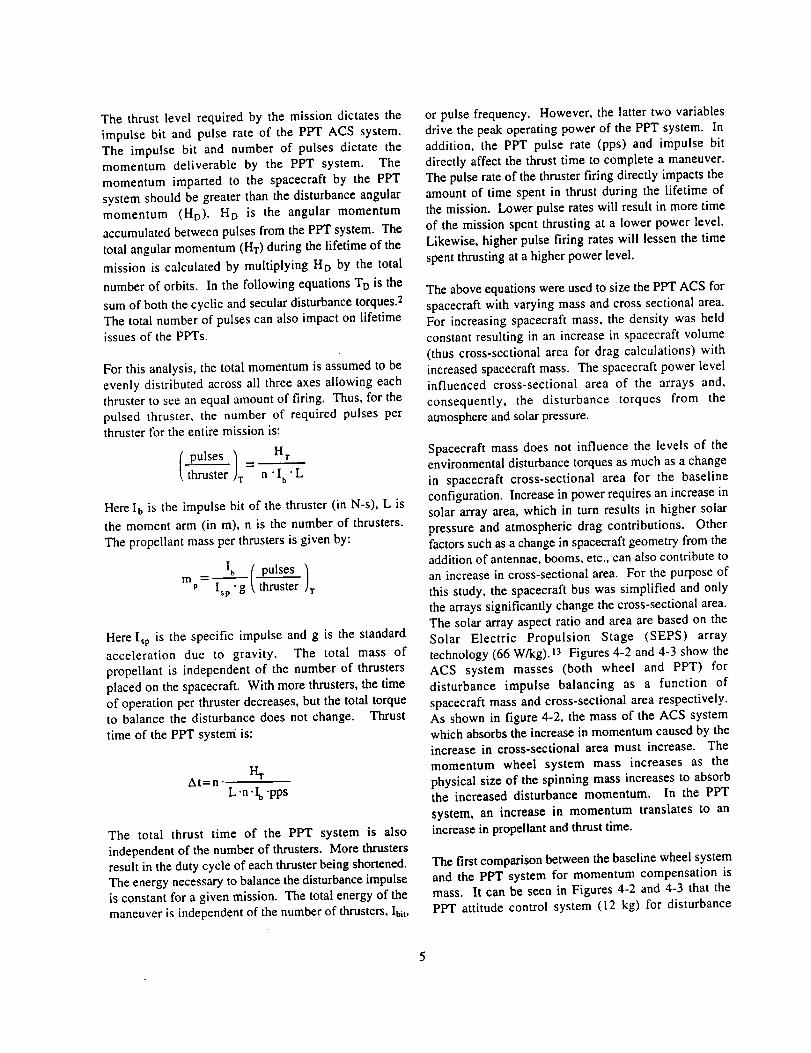
Thethrustlevelrequiredbythemissiondictatestheimpulsebit andpulserateof thePPTACSsystem.Theimpulsebit andnumberof pulsesdictatethemomentumdeliverableby thePPTsystem.Themomentumimpartedto thespacecraftby thePPTsystemshouldbegreaterthanthedisturbanceangularmomentum(HD). HD is the angularmomentumaccumulatedbetweenpulsesfromthePPTsystem.Thetotalangularmomentum(HT)duringthelifetimeofthemissioniscalculatedbymultiplyingHDby thetotalnumberoforbits.In thefollowingequationsTO is the
sum of both the cyclic and secular disturbance torques. 2
The total number of pulses can also impact on lifetime
issues of the PPTs.
For this analysis, the total momentum is assumed to be
evenly distributed across all three axes allowing eachthruster to see an equal amount of firing. Thus, for the
pulsed thruster, the number of required pulses perthruster for the entire mission is:
pulses] Hrthruste-"""_}r - n • I b • L
Here I b is the impulse bit of the thruster (in N-s), L is
the moment arm (in m), n is the number of thrusters.
The propellant mass per thrusters is given by:
Ibm = -- I thruster rP Isp "g
Here Isp is the specific impulse and g is the standard
acceleration due to gravity. The total mass of
propellant is independent of the number of thrusters
placed on the spacecraft. With more thrusters, the time
of operation per thruster decreases, but the total torqueto balance the disturbance does not change. Thrust
time of the PPT system is:
At=nL-n .Ib -pps
The total thrust time of the PPT system is also
independent of the number of thrusters. More thrustersresult in the duty cycle of each thruster being shortened.
The energy necessary to balance the disturbance impulse
is constant for a given mission. The total energy of the
maneuver is independent of the number of thrusters, Ibi t,
or pulse frequency. However, the latter two variables
drive the peak operating power of the PPT system. Inaddition, the PPT pulse rate (pps) and impulse bit
directly affect the thrust time to complete a maneuver.
The pulse rate of the thruster firing directly impacts theamount of time spent in thrust during the lifetime of
the mission. Lower pulse rates will result in more time
of the mission spent thrusting at a lower power level.
Likewise, higher pulse firing rates will lessen the time
spent thrusting at a higher power level.
The above equations were used to size the PPT ACS for
spacecraft with varying mass and cross sectional area.For increasing spacecraft mass, the density was held
constant resulting in an increase in spacecraft volume
(thus cross-sectional area for drag calculations) with
increased spacecraft mass. The spacecraft power levelinfluenced cross-sectional area of the arrays and,
consequently, the disturbance torques from the
atmosphere and solar pressure.
Spacecraft mass does not influence the levels of theenvironmental disturbance torques as much as a change
in spacecraft cross-sectional area for the baseline
configuration. Increase in power requires an increase in
solar array area, which in turn results in higher solar
pressure and atmospheric drag contributions. Other
factors such as a change in spacecraft geometry from theaddition of antennae, booms, etc., can also contribute toan increase in cross-sectional area. For the purpose of
this study, the spacecraft bus was simplified and onlythe arrays significantly change the cross-sectional area.
The solar array aspect ratio and area are based on the
Solar Electric Propulsion Stage (SEPS) array
technology (66 W/kg). 13 Figures 4-2 and 4-3 show the
ACS system masses (both wheel and PPT) for
disturbance impulse balancing as a function of
spacecraft mass and cross-sectional area respectively.As shown in figure 4-2, the mass of the ACS systemwhich absorbs the increase in momentum caused by the
increase in cross-sectional area must increase. The
momentum wheel system mass increases as the
physical size of the spinning mass increases to absorbthe increased disturbance momentum. In the PPT
system, an increase in momentum translates to an
increase in propellant and thrust time.
The first comparison between the baseline wheel system
and the PPT system for momentum compensation ismass. It can be seen in Figures 4-2 and 4-3 that the
PPT attitude control system (12 kg) for disturbance

torquecompensationis50%to 25%ofthemassof themomentumwheelsystem(20-40kg) for varyingspacecraftmass.Inthecaseofvaryingspacecraftcross-sectionalarea,thePPTACSmassis50%to 12%ofthemassof themomentumwheelsystem(20-80kg).
Theenergyof thePPToperationin themaneuverdeterminesthepowerrequirementsto thissubsystem.Theenergyperpulse(Ep)multipliedbythenumberofpulsesperseconddefinestheaveragepowerof thePPTsystem.PeakpowerlevelswhilethePPTsarefiringaredirectlyrelatedto impulsebitandpulserateatwhichtheyareoperating.A maneuverrequiringmorethrustwillalsorequireahigherpowerlevel.
In orderto determinewhetherthis is a reasonablesystemfromthestandpointofoperationandlifetimeofthePPTs,thenumberof pulsesandpowerlevelsofthePPTs to perform the momentumbalancingiscalculated.Thenumberofpulsesperthrusterincreasesas the amountof disturbanceangularmomentumincreases.At thelowend(spacecraftmass100kg,arraycross-sectionalarea1.7m2),thereare1.5x106pulsesrequiredper thruster,andat the highend(spacecraftmass300kg,andarraycross-sectionalarea3.2m2)thenumberof pulsesrequiredperthrusteris3.18x106.Botharewellundertheexpectedlifeof 107pulses. TheaveragepowerconsumedbythePPTsystem for angular momentumcompensationthroughoutthefiveyearlifeofthespacecraftisconstantfora givenspacecraftconfiguration(massandcross-sectionalarea).Animpulsebitof 580I.tNsisusedinboththePPTwithIsp1000sandIsp1500s.Forthelowendmentionedpreviously,theaveragepoweris0.08WforthePPTswithIspof 1000s,and0.13W forPPTswithIspof 1500s,and0.37W. At thehighendconfiguration,theaveragepoweris 0.18W for thesystemwith Ispof 1000s and0.28W forthe1500ssystem. Theseaveragepowernumbersresultin9.42x10-3and2.01x10-2pulsesperthrusterpersecondrespectivelyoverthelifetimeof thespacecraft.Thisamountstoapulseroughlyeveryonetotwominutes.Thedeadbandangularspacecraftdriftbetweenpulsesforthesetwopowerlevelsis0.03° and 0.014" respectively.
Higher frequencies will result in smaller deadband
angles. The average power during operation is driven
by the pulse frequency at which the PPTs are fired.
Higher pulse frequencies result in higher average power
levels. For example, in the low end spacecraft case, a
pulse frequency of 0.05 Hz results in average power
during firing of 0.9 W, where a frequency of 3 Hz
results in a average power of 54.8 W. Therefore, the
power consumption of the PPT system is a function ofthe demands of the mission.
4.4 SLEWING MANEUVERS
A second function for which the PPTs are analyzed is a
slew maneuver of 360* (2r_) about one axis. Assuming
that the spacecraft is in an unknown orientation and it
must rotate about one axis, the maneuver is split into
two PPT firing sequences in opposite directions. Two
PPTs in a pure couple configuration pulse one half ofthe maneuver to start the rotation, and one half to stop.
For slewing maneuvers in which a large angular
rotation to the vehicle is required, the required PPT
power levels increase as the required maneuver timedecreases.
The power averaged over the entire maneuver duration is
solved independent of pulse rate or impulse bit for these
calculations, and is solely a function of time required for
the maneuver. The following equation shows power asa function of maneuver time.
0Pavg _
rI'L'(AT _
Here, 0 is the slew maneuver angle, Isp is the specific
impulse of the PPT, g is the gravitational constant, I_n
is the moment of inertia of the spacecraft, ri is the
efficiency of the thruster system, L is the moment arm,and AT is the maneuver time. Therefore, a 0 of 2n is a
worst case slew maneuver, and smaller angles will
result in smaller average power requirements.
In the case of the complete rotation, as the time
constraint is reduced, a larger torque is needed and
therefore the PPT must provide either a higher impulse
bit or higher pulse rate. Each of these increases results
in a higher average power for the PPT system. Theresult is illustrated in Figure 4-4 which shows the
average power levels of different I_ PPTs versus the
time required for a complete 360* spacecraft rotation.
The spacecraft assumptions include a moment arm of0.5 m, and moment of inertia (Icm) of 80 kg-m 2. For
maneuver time requirements of less than 10 minutes,
average power levels are 200 W and greater. If morethan 50 minutes is allowed to the maneuver, the average
power levels are 10 W and lower. These power levelsonly need to be sustained during the slew maneuver and

couldbesuppliedfrombatteries.FromFigure4-4,averagepowerversustime to performthe slewmaneuver,it canbeseenthatthelowerthetime,thehigherthepowerrequirementfromthePPTsystembecomes.Formaneuversthatmustbeperformedinaminute,thePPTpowerreaches10,000W, andofcourseasymptoticallyapproachinfinityasthemaneuvertimegoestozero.However,if thetimesarerelaxed,the PPTsystembecomemore feasiblefor thisapplication.An alternatepointof viewof thePPTsystemforslewmaneuversis presentedinFigure4-5.Timeof maneuveris alsoafunctionof pulserateforvaryingimpulsebits. Pulseratein turndrivestheaveragepowerrequiredfromthePPTsystem.ThisanalysisservestocorroboratetherelationshipbetweentimeofmaneuverandaveragepowerrequirementsofthePPTsystem.
5.CONCLUSION
Thisstudydemonstratedthefeasibilityofusingpulsedplasmathrustersto providethemomentumlevelsneededtobalancethedisturbancetorquesimpartedtoasmall(100- 300kg)spacecraftinLEO.BecauseoftheirhighI_p(1000to 2000sec),PPTsusea smallamountof propellantto performthe equivalentmaneuverof a hydrazinethrustersystem. The12thrusterredundantPPTACSconfigurationsin thisstudywereconsistentlyhalfthemassor lessof anequivalentbaselinemomentumwheelsystem.Averagepowerlevelsfor theattitudecontrolfunctionsrangefrom0.08W to0.28Win worstcasescenarios.PPTACSsystemsusedfor environmentaldisturbancecompensationarelessmassiveandrequireloweraveragepowerthanthecounterpartwheel/thrustersystems.Therefore,it is feasibleto usePPTsto performthemomentumcounteringfunctionsofmomentumwheelssystems.
Forslewingmaneuvers,thePPTsystemperformswellfor maneuversthataregivenlongertimetocomplete.AveragepowerlevelsforslewingmaneuversrangefromI0 W or lessfor timesof greaterthan50minutes.Maneuversoflessthan10minuteswouldrequirelargerpowerlevels,ora differenttypeof actuator,suchasthrustersoramomentumwheel.
Furtherworkremainsin theareasofcontrolsandtorquematchinginordertobettermodeltheuseof PPTsforattitudecontrol.Additionally,theareaof deadbandcontrolthroughtheuseofpulsedplasmathrustersisa
nextlogicalstepinthestudyof theapplicationof PPTstosmallsatelliteattitudecontrol.
6.REFERENCE
t Myers,RogerM., StevenR. Oleson,MelissaMcGuire,NicoleJ. MeckelandR.JosephCassady,"PulsedPlasma Thruster Technology for Small Satellite
Missions," NASA Contractor Report 198427,
November 1995; see also Proceedings of the 10th
USU/AIAA Small Satellite Conference, Sept. 1995.
2 Larson, Wiley J., and James R. Wertz (ed.),
Mission Analysis and Design, Microcosm Inc, and
Kluwer Academic Publishers, Torrance, 1992.
3 Selding, Peter B., " Reaction Wheel Concern CloudsNov. 23 SOHO Launch," Space News, November 6-12,
1995.
4 SMEX homepage, http://sunland.gsfc.nasa.gov/
smex/smexhomepage.html, March 27, 1996.
5 Todd Mendenhall, TRW, personal communication,
August 21, 1995.
6Brill, Y., A. Eisner, and L. Osborn, "The Flight
Application of a Pulsed Plasma Microthruster; theNOVA Satellite," paper no. AIAA-82-1956,AIAA/JSASS/DGLR 16th International Electric
Propulsion Conference, 1982.
7Ebert, W.L., S.J. Kowal, and R.F. Sloan,
"Operational Nova Spacecraft Teflon Pulsed PlasmaThruster System," paper no. AIAA-89-2497,AIAA/ASME/SAE/ASEE 25th Joint Propulsion
Conference, Moneterey, CA, July 10-12, 1989.
8 Ithaco, Inc., online catalog located at
http:llwww.newspace.comlindustrylithaco, March 5,1996.
9 Satellites International Limited, online catalog at
http:llwww.sil.comlspacel9sacemds.html, March 4,1996.
10Fortescue, Peter and John Stark, Spacecraft Systems
F,.o.gJ/lg..c_d._, Wiley Publishers, Chichester, 1991.
I I Carl Englebrecht, Jet Propulsion Laboratory,Personal communication, April 1, 1996.
t2 SteveAndrews, Goddard Space Flight Center,
personal communication April 2, 1996.
13 SEPS technology developed by Lockheed Missies
and Space.

TOMS-EP WIREWetmass 288.6 k_zDryMass 21 6 kg
3 reaction wheels 27.6 kg
electronics 5.85 kg
3 magnetic torque rods _.58 kgtotalACS mass 42.03 kg
Mass fraction of ACS 20 %
Wet mass
Dry Mass4 reaction wheels
3 torque rods
250
14.4
7.24
Mass total ACS massfraction of ACS
21.6
9
Table 2-1: Example Spacecraft Attitude Control Systems
kj_
kg
kg
kg
kg
%
Specifications
unit dry mass (kg)
6 thruster dry mass (kg)
12 thruster dry mass (kg)
total impulse (N-s)
efficiency (%)
Iso (sec)
LES 8/9 Current
5.2 2.7
10.4 5.4
20.8 10.8
10000 20000
8 16
1 000 1000
I 2.7
5.4
i 10.8i
i 20000
i 16
1 500
Table 3-1: Pulsed Plasma Thruster Characteristics
I NextGeneration
! 5.zi 1 0.4
I 20.820000
16
! 2000
[ Solar Pressure i Ts'
Aerodynamic i Ta !!
Gravity gradient i Tgi
Magnetic Field !Tm i
Total torque: i Td!
1.9E-06
8.7E-05
3.9E-07
2.6E-05
1.1E-04
Table 4-1: Magnitudes of Disturbance Torques at 400 kmAltitude
Component Value
wheel speed 3000 rpmdisk radius 0.08 m
individual spinning mass 3.60 kgdrive electronics 0.91 kg
total structure (4 wheels) 2.00 kg
dumping thruster mass 0.4 kgtotal thruster mass (6) 2.4 kg
200s Isp propellant mass 5.23 kg
280s Isp propellant mass 3.73 kg
Totals: 4 wheels & 6 thrusters
Four wheel system mass 20.04 kg
six thruster 200 Isp mass 7.63 kg
six thruster 280 Isp mass 6.13 kg
Table 4-2: Four wheel system baseline
assumptions

'rEFLON
Figure 3-l: PPT flight system schematic.Telemetry signals depend on application.
(D|
Z::L
i
rn
|
LU¢D--I
Ii
100000
10000
1000
100
10
ImpBit-DischEdataAemDes
SIDE-FEED(1.0)FAILEDQUAL IN '87
(POWER, kW)
FLIGHT PROGRAMS
TIP-IINOVA 1-3(0.035)
L-4SC-3.__ _ SMS
MDT-2A" - LES-6 (0.0025)
NASA LeRC/OlinProgram
LES-8/9 (0.025)
1 10 100 1000
DISCHARGE ENERGY, J
Figure 3-2: Impulse bit vs. stored energy for arange of flight and flight-qualified PPT systems.
10

Total of 12 PPTs
Two per spacecraft face
°/
!
/
Axes Key:
z axis
Nadir vector
x axis
Velocity vec
y axis
Negative orbit normal
Figure 4-1: Generic Spacecraft Illustrating Pulsed Plasma Thruster Placement
11

r
45 - -t .... LES 8/9 PPTPPT Isp 1000s
.... PPT Isp 1500s
40 ...... . ...... PPT lsp 2000s
' _ Wheels w/N2H4@200s
, ,I ....... I,,
TOMS-I_
.............. . _ ............. ;............................................35 ..... ' _ - Wheels w/N2H4@ 280s
i i : o i
_.:i: !
20 .............................................................................................................................................................! Altitude 400kin, array cross-sectional area 1.7 m2
i 6 N,H4 thrusters for dumping
.................... i......................i......................':"'"l "12PPTs,lb 580p.Ns!
II--. I_'-. am,-._ row"° _'o _"_o Ira--. _'. ram--. _'. I,l--. I_'. It". liE'.:
.... I .... I[ .... I, .... I .... ,I .... tl ....
50 100 150 200 250 300
Spacecraft mass (kg)
Figure 4-2: Attitude Control System Mass forVarying Spacecraft Mass
15-
10
0 350
E I.... _,_ w/N_2_H_47 2_0(_)_s i !! -"
"80-_--_4@ 280s ............ ;.................. !.................. i.;.-n---.--, i-
I I.... LEg S/9 _ !i !i .." _ /
: I Pzr.; .";-i"
60 0.of !
.................... !......-.._..._..;.....................................i.....................................50- o°_ i
• • Altitude 400 kin, Spacecraft mass 150 kg................................. j._._.. .......... L............. 12 PPTs, Impulse bit 580 I.tNs ........
40- il ,f • _.: [ 6 hydrazin¢ thrusters in wheel system
i i .................................30..................................._........... ! !
.....--_. _ _ m._.---- _._---.-- _ms.-i ..- _-_-'--" _-_----" --_'_" _-"20 ........................................................................................................................................................
10 .............. "'"_" .... "
•6 1.8 2 2.2 2.4 2.6 2.8 3
Total Spacecraftcross-SectionalArea (m2)
Figure 4-3: Attitude Control System Mass forVarying Array Cross-Sectional Area
1.2
12

103
10z
s
10
<
0.1
: i
\_', _ _ I I -- so kg-m2 I :t
_,, ! i I Rotation 2, I_, • i :: I Efficiency L6% l -I
",'.'. i i / MomentArm0.5mI_.]_'_i _..........................................................................1 I
X4 ..,, :: i
i _ _,._'_ . :
F ..... ISD=1500,i , ---- "--, .....
-- -- - Isp = 1000s _ "- -..
_ I ..... Isp=2000s] :!
| .... I ........ I ....0 50 100 150 200
Time (rain)
Figure 4-4: PPT System Power Levels for Time toAccomplish 2_ Slewing Maneuver
104
10 3_
I0z-
S I0
:=- I
0.1
! ' , !: i
| : :
..... lbit = 20l.tNs
Ibit = 50_qs
Ibit = 5001.tNs
Ibit = 10001aNs
_: ,b ! .................................... _,..,- ......................... +_,_ ................... _--'_'_"2 .......... :
0 50 100 150 200
Time of Maneuver (rain)
Figure 4-5: Pulse Firing Rates of Differing Impulse Bitsfor 2x Maneuver Times
13

Form ApprovedREPORT DOCUMENTATION PAGE OMBNo.0704-0188
p,_= _,.u_ _ _ thl _ o__ .o_=_. _ _ ._,_,d w.m_'._ z.heur _ y._po_... __¢_ _ _met_ ,_ ._a_.._t_,po_..,_p=ing _ _ -_._tMr_¢ and m=au_nzngthedatamedM. a_. =om?_.ng .apo.r*vmmO_ ._.a,pon.= _o*_. _ _¢_m_= r.eW.o_ Lr_..oymn *if.,m=__.ary__op_...a,,p_._0, m,co,actlon of Infomlatlon. including luggestioca 10¢ reducing fit*= oumen, to wunlngton Heaoquanprl u__rv_, uwecto_. _ IO¢_lnlormm__j b_)en__,_l. ia_olm=_. 1;.1= oenersoftDavb Highway. Suite 1204. Arlington. VA 222O2-4302. and to the Office ¢t Man_eeaent ant Uu(_et. paperwork Reductmn Project (0704-O188). was _gton. IX; 2050_
1. AGENCY USE ONLY (Leave blank) 2. REPORT DATE
August 1996
4. TITLE AND SUBTITLE
Pulsed Plasma Thrusters for Small Spacecraft Attitude Control
e. AUTHOR(S)
Melissa L. McGuim and Roger M. Myers
7. PERFORMING ORGANIZATION NAME(S) AND ADDRESS{ES)
Analex Corporation3001 Aerospace ParkwayBrook Park, Ohio 44142
9. SPONSORING/MONITORING AGENCY NAME(S) AND ADDRESS(ES)
National Aeronautics and Space Administration
Lewis Research CenterCleveland, Ohio 44135-3191
3. REPORT TYPE AND DATES COVERED
Final Contractor Report5. FUNDING NUMBERS
WLL-233-03--05
C-NAS3-27600C-NAS3-27186
8. PERFORMING ORGANIZATION
REPORT NUMBER
E--I0395
10. SPONSORING/MONITORING
AGENCY REPORT NUMBER
NASA CR-198517
11. SUPPLEMENTARYNOTES
Melissa L. McGuire, Analex Corporation, 3001 Aerospace Parkway, Brook Park, Ohio 44142 (work performed underNASA Contract NAS3-27600), and Roger M. Myers, NYMA, Inc., 2001 Aerospace Parkway, Brook Park, Ohio 44142
(work performed under NASA Contract NAS3-27186). Project Manager, Sandra L. Hardy, Engineering Systems DivisionNASA Lewis Research Center, organization code 4420, (216) 433-2278.
12,, DISTRIBUTION/AVAILABILITY STATEMENT 12b. DISTRIBUTION CODE
Unclassified - Unlimiled
Subject Categories 18 and20
This publication is available fi_om the NASA Center for AeroSpace Information, (301) 621-0390.
13. ABSTRACT (Maximum 200 words)
Pulsed Plasma Thn_ters (PITs) are a new option for attitude control of a small spacecraft and may result in reducedattitude control system (ACS) mass and COSLThe primary purpose of an ACS is to orient the spacecraft to the desiredaccuracy in inertial space. The ACS functions for which the PPT system will be analyzed include disturbance torque
compensation, and slewing maneuvers such as sun acquisition for which the small impulse bit and high specific impulse
of the PPT offers unique advantages. The NASA Lewis Research Center CLeRC) currently has a contracted flight PPT
system development program in place with Olin Aerospace with a delivery date of October 1997. The PPT systems in thisstudy are based upon the work being done under the NASA LeRC program. Analysis of the use of PPTs for ACS showedthat the replacement of the standard momentum wheels and torque rods with a PPT system to perform the attitude control
maneuvers on a small low Earth orbiting spacecraft reduced the ACS mass by 50 to 75% with no increase in required
power level over comparable wheel-based systems, though rapid slewing power requirements may present an issue.
14. SUBJECT TERMS
Spacecraft attitude control; Palsed plasma thrusters; Low Earth Orbit (LEO)
17. SECURITY CLASSIFICATION
OF REPORT
Unclassified
18. SECURITY CLASSIFICATION
OF THIS PAGE
Unclassified
NSN 7540-01-280-5500
19. SECURITY CLASSIFICATION
OF ABSTRACT
Unclassified
15. NUMBER OF PAGES
16. PRICE CODE
A0320. LIMITATION OF ABSTRACT
Standard Form 298 (Roy. 2-89)
Prescribed by ANSI Std. Z39-18298-102


"0o"-tE
Oq-tIll.=.
C
@o"
IOo
Z
"n
r.-3
o
C
_0 __
_o