public exhibition information - nhk tv user interface full-resolution super hi-vision camera system...
TRANSCRIPT
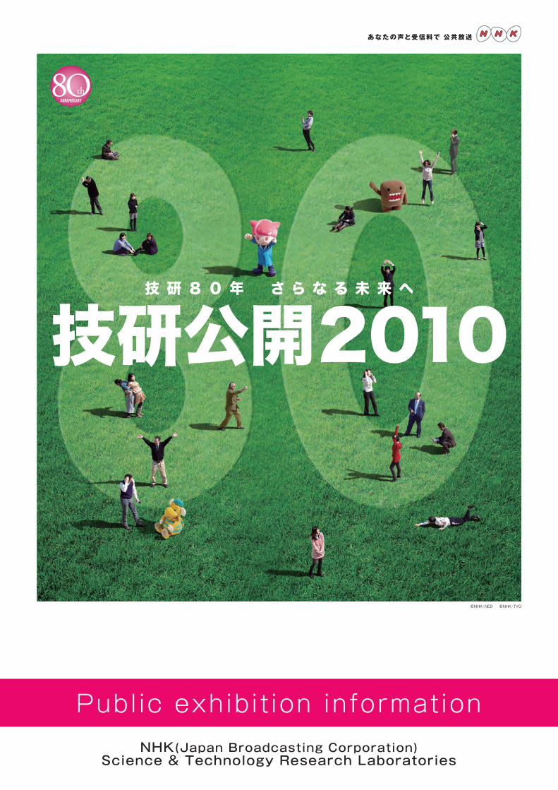
Public exhibit ion informationNHK(Japan Broadcasting Corporation)
Science & Technology Research Laboratories10 10

G r e e t i n g s
Thank you for your continued support of NHK, Japan’s public broadcaster. This year marks the eightieth anniversary of the NHK Science & Technology Research Laboratories (STRL). Throughout the history of broadcasting, STRL has always been a pioneer of cutting-edge broadcast technologies, from early innovations in television and color broadcasting to recent developments such as Hi-Vision and satel-lite and digital broadcasting. STRL has been an important part of the evolution of broadcasting in Japan and the world. STRL plays the same role today that it always has̶working on short-term research to find solutions to the pressing business issues of the day, while forging ahead with long-term research to create new services for the next era. To provide the wealth of broadcasts needed to satisfy viewers in the coming era of merged broadcast and telecommunications formats, STRL is working on R&D projects that span a wide range of scientific and engineering fields, from human physiology to devices and systems. STRL has always been a dedicated provider of technological platforms in tune with the times. The theme for this year’s Open House is STRL’s 80th Anniversary:
Delivering the Future to you. The results of forty-four of the latest R&D projects will be on display, along with the latest program tech-nology used in broadcasts. Exhibits will cover areas such as advanced technology for Super Hi-Vision and the new services of the “3-Screens” era, as well as technology for user-friendly broadcasting. For the past eighty years, STRL’s pioneering researchers have held an unwavering faith in the future of broadcasting, and they have worked steadily to advance the field. Today, our mission is to keep this faith. We hope for your continued support for our activities.
May , 2 0 1 0
Ke i i ch i Kubo t a ,D i r e c t o r -Gene r a l ,NHK Sc i ence & Techno l ogy Re s e a r ch Labo r a t o r i e s
10 10
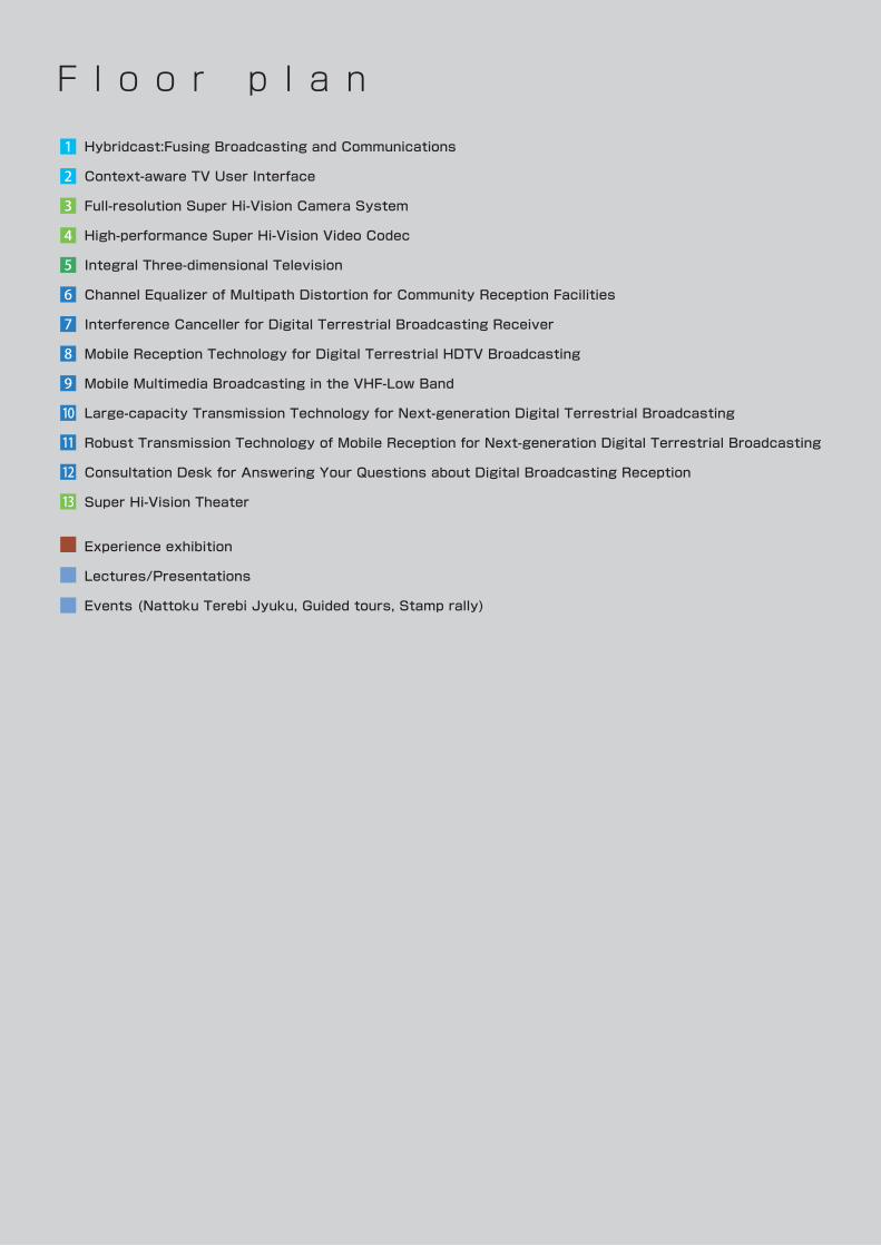
F l o o r p l a n
Hybridcast:Fusing Broadcasting and Communications
Context-aware TV User Interface
Full-resolution Super Hi-Vision Camera System
High-performance Super Hi-Vision Video Codec
Integral Three-dimensional Television
Channel Equalizer of Multipath Distortion for Community Reception Facilities
Interference Canceller for Digital Terrestrial Broadcasting Receiver
Mobile Reception Technology for Digital Terrestrial HDTV Broadcasting
Mobile Multimedia Broadcasting in the VHF-Low Band
Large-capacity Transmission Technology for Next-generation Digital Terrestrial Broadcasting
Robust Transmission Technology of Mobile Reception for Next-generation Digital Terrestrial Broadcasting
Consultation Desk for Answering Your Questions about Digital Broadcasting Reception
Super Hi-Vision Theater
Experience exhibition
Lectures/Presentations
Events (Nattoku Terebi Jyuku, Guided tours, Stamp rally)
1
2
3
4
5
6
7
8
9
10
11
12
13
10 10
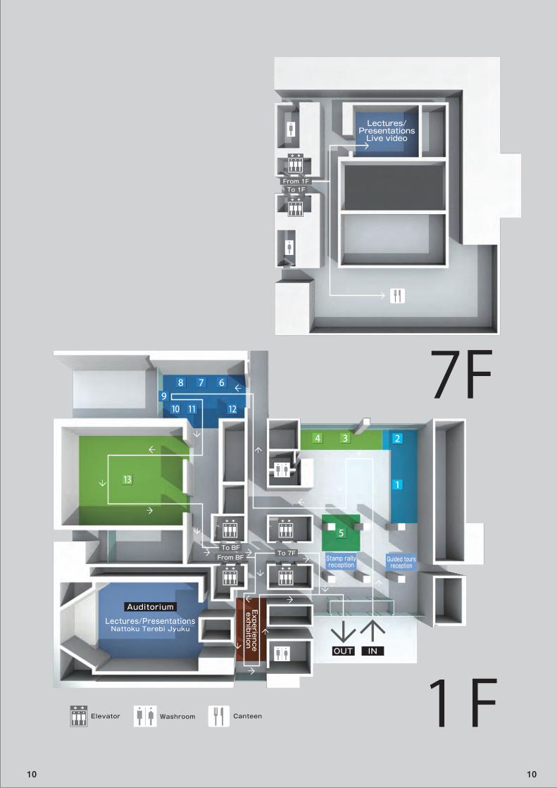
Guided toursreception
Stamp rallyreception
Auditorium
Lectures/PresentationsNattoku Terebi Jyuku
Lectures/PresentationsLive video
Experienceexhibition
OUT IN
To BFFrom BF
To 7F
From 1FTo 1F
Elevator Washroom Canteen
1
234
666
8
910 11 12
15 1
234
678
5
910 11 12
13
1F
7F
10 10
F l o o r p l a n
Eighty Years of STRL Achievements
Multi-modal Information Presentation System for the Visually Impaired
Translating Japanese into Computer-animated Japanese Sign Language
Live Closed-captioning using Speech Recognition
Automatic Evaluation of Program Sound Balance for the Elderly
Automatic Detection of Unpleasant Scenes
Cable Television System for Super Hi-Vision
Optical LAN for Super Hi-Vision
Lightweight Loudspeaker using Polymer Films
58-inch Diagonal Ultrahigh-Definition Plasma Display with 0.33-mm Pixel Pitch
Wide-gamut Colorimetry for Super Hi-Vision
Home Reproduction of Super Hi-Vision Audio
22.2 Multichannel Sound Production System
Identity-Web Services Framework between Broadcasting and Communication Services
Secure Content Distribution Services
Digital Watermarking System for Content Distribution over the Internet
Comment Analysis for Social TV Services
Relevant Retrieval System for NHK Creative Library
CG Content Production Services using Cloud Computing
Flexible Program Production System
Lighting Device Technology using Organic Light Emitting Diodes
Advanced FPU Mobile Relay System
Millimeter-wave TV Camera
The VFX World of “Saka no Ue no Kumo”
Licensing and Applicational Development of NHK’s Technology
Haptic Technology for Representing 3-D Objects
Organic Image Sensor
HARP Imaging Device using Fiber Optic Plate
Flexible Organic Light Emitting Diode Display
Recording System using Thin Optical Disks
High-density Holographic Recording Technology
Poster Exhibit
Video Showcase of Open House 2010 on the Internet (Video streaming)
14
15
16
17
18
19
20
21
22
23
24
25
26
27
28
29
30
31
32
33
34
35
36
37
38
39
40
41
42
43
44
10 10
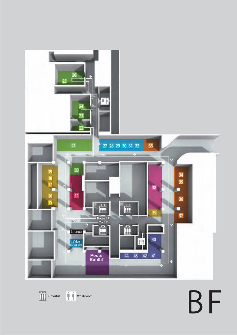
BF
1618
22 24 30
3132
33
35
36
36
37
14
1620
151816
181718181819
21252126
21 27 2428 2429 2430 2431 2432 33
3435
36
37
38
40
3639
41424344
From 1FTo 1F
Lounge
Videostreaming
PosterExhibit
2122
2123
2124
Elevator Washroom
1Fusion of Broadcasting and Communications
Hybridcast : Fusing Broadcasting and CommunicationsAdvanced broadcast services for the “3-Screens” era
Broadcasting and broadband communications networks can be used together to provide services that are more convenient and enjoyable for viewers. This exhibit presents examples of such Hybridcast services that will be technologically feasible in the near future.
O u t l i n e
We are laying the groundwork for a variety of new broadcast services that will be in tune with future needs of our viewers in the “3-Screens” era.
In the works
Extra content servicesHybridcast services can augment programs being broadcast with content provided over a broadband communications network. The receiver combines the broadcast with content additional content, such as closed captions, sound, and video, and this makes it possible for a service to be tailored to individual viewer needs.
Social networking TV servicesSocial networking TV services will combine broadcast programs with Internet social networking services※1 to form “program communities” that viewers can take part in while watching the program. These services will give viewers a new venue for communicatng with other viewers.
Program recommendation servicesHybridcast services will draw on a wide range of TV program information to provide viewers with up-to-date program recommendations. Recommendations will be based on information related to programs on the air, the viewer’s profile, and comments on programs from other viewers.
Cross media servicesHybridcast services will have a number of functions for more convenient viewing on TV sets and mobile terminals. For example, the bookmark function will let viewers register their favorite programs for later viewing on a TV, PC, or mobile terminal. By using the interworking function, viewers will be able to look for a program on their mobile terminal and watch it on their home TV set.
※1 Social networking service : A service that connects persons with persons by using the Internet
F e a t u r e s
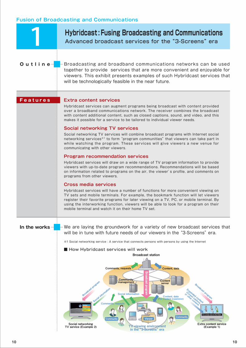
■ How Hybridcast services will workBroadcast station
Comments, requests Content, data
Social networkingTV service (Example 2)
Extra content service(Example 1)
Contentserver
Social information
Comments, requests
Broadcast pro
gram Broadcast program
Social information
Content, data(For content expansion)
Expanded content
(Closed captions
or other content)
TV viewing environmentin the "3-Screens" era
CommunityCommunity
Viewer
超感動!!私も行きたい~うらやましいなあCGみたい
It’s a close race to the finish...
Communitymanagement
Broadcast program
10 10
Fusion of Broadcasting and Communications
2 Context-aware TV User InterfaceMaking viewing easier
STRL is working on a TV user interface incorporating context recognition technologies that can understand a viewer’s situation and display content that he or she is interested in. This exhibit shows how the interface will maintain its awareness of the viewer and know how to select content he or she will want to watch.
O u t l i n e
We will improve the precision of image and voice recognition technologies involved in viewer context recognition. We wish to develop a technology that can accurately infer a viewer’s intent from various recognition results.
In the works
Understands viewer context automaticallyBy integrating image and voice recognition results with content metadata and time information, the interface can identify the viewer and make inferences about what s/he is doing and what s/he may want to view. It then offers content selections that it believes will be appropriate for his/her situation.
Infers desired content from physical cluesThe context recognition technology seamlessly connects the viewer’s immediate physical space with the information space containing the content that s/he is probably interested in. For example, by recognizing objects around the viewer, the interface can automatically offer content related to those objects.
F e a t u r e s
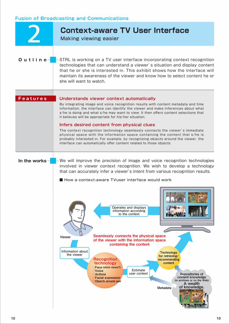
■ How a context-aware TVuser interface would work
Technologyfor retrieving/recommending
content
Viewer
Operates and displaysinformation according
to the context
Information aboutthe viewer
Estimateuser context
Seamlessly connects the physical spaceof the viewer with the information space
containing the content
Recognitiontechnology
○Face (which viewer?)○Voice○Actions○Facial expression○Objects around user
Repositories ofcontent knowledge
(in archives or on the Web)
MetadataA wealth
of knowledge.
10 10
Super Hi-Vision
3 Full-resolution Super Hi-Vision Camera SystemUltrahigh-definition images from camera with three 33-million-pixel image sensors
STRL is working on a full-resolution Super Hi-Vision (SHV) camera using three image sensors, each with 33 million pixels. We recently developed a prototype color camera that uses signal processing to compensate for chromatic aberration of the lens and has a compact transmitter between the camera head and camera control unit.
O u t l i n e
We will use this camera to shoot various full-resolution SHV videos. We will continue to develop camera prototypes that will be needed to determine the video parameters that will make the color reproduction and dynamic range of SHV superior to those of HDTV.
In the works
Signal processing that compensates for lateral chromatic aberration※1 of lensIt is very difficult to compensate for chromatic aberration of the lens by using optical methods alone. We recently developed a high-precision chromatic aberration compensation technology using signal processing that accounts for zoom, iris, and focus settings. The compensation can be done in real-time.
Compact signal transmitter bridges between camera head and camera control unitIn 2009, we developed a wavelength division multiplex※2 transmitter able to transmit SHV video on a Hi-Vis ion camera cable. This year, we improved the ease of operation while shooting by making the transmitter more compact and mounting it inside the camera head.
Adjustable focus through camera viewfinderThe low resolution of camera viewfinders has made it difficult for cameramen to find the in-focus range and adjust the focus. We made this task easier by adding an auxiliary signal to the viewfinder image that indicates the in-focus range.
F e a t u r e s
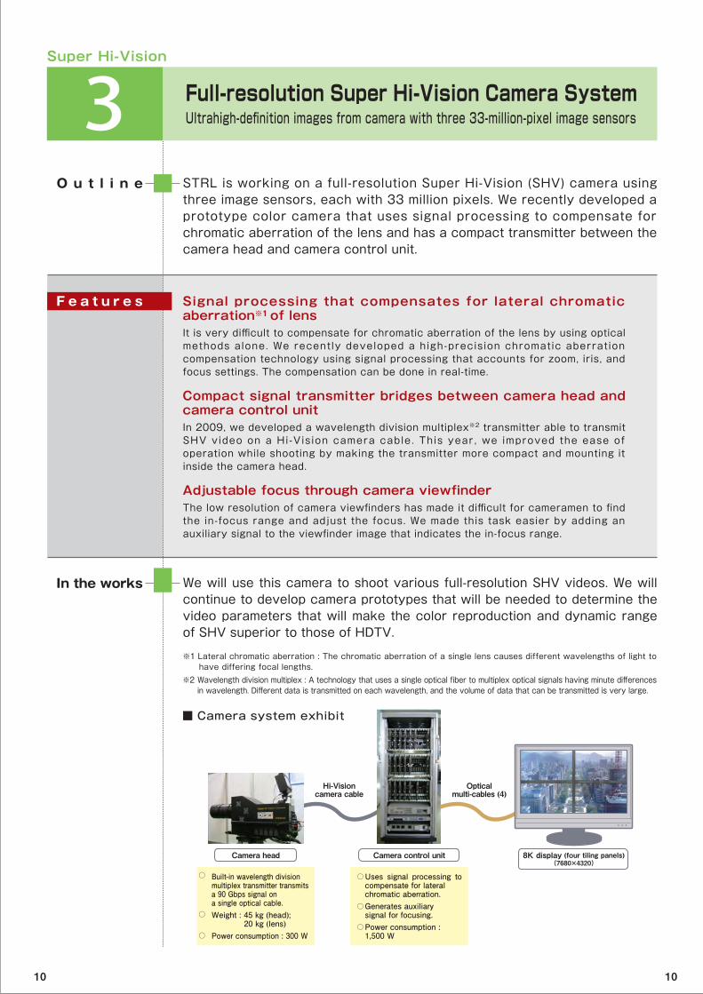
■ Camera system exhibit
※1 Lateral chromatic aberration : The chromatic aberration of a single lens causes different wavelengths of light to have differing focal lengths.※2 Wavelength division multiplex : A technology that uses a single optical fiber to multiplex optical signals having minute differences in wavelength. Different data is transmitted on each wavelength, and the volume of data that can be transmitted is very large.
Built-in wavelength divisionmultiplex transmitter transmits a 90 Gbps signal on a single optical cable.Weight : 45 kg (head); 20 kg (lens)Power consumption : 300 W
Camera head
Uses signal processing to compensate for lateralchromatic aberration.Generates auxiliarysignal for focusing.Power consumption : 1,500 W
Camera control unit 8K display (four tiling panels)(7680×4320)
Opticalmulti-cables (4)
Hi-Visioncamera cable
○ ○
○
○
○
○
10 10
Super Hi-Vision
4 High-performance Super Hi-Vision Video CodecFor high-quality SHV transmissions in various media
To help pave the way for SHV (Super Hi-Vision) broadcasting, STRL has developed a new codec system that can encode and decode SHV signals in real time. This efficient compression system maintains high picture quality by using 60p (60 frames per second) encoding units and an SHV format converter with signal compensation processing.
O u t l i n e
We will use the codec in SHV signal transmission experiments.
This research is jointly carried out with FUJITSU LABORATORIES Ltd.
In the works
Video encoding system for broadcasting experimentsThe codec consists of eight hardware encoding units (conforming to the MPEG-4 AVC/H.264※1 High Profile standard). The units encode spatially divided SHV signals in real time.
60p (progressive scanning) encoder unitsEach hardware encoding unit supports a resolution of 1,920 × 1,080 pixels (60p). These units derive the maximum benefit from the temporal correlation of video signals by processing the SHV video signals without temporal division.
Signal compensation processA new converter was developed to compensate for the signal position gaps unique to the Dual Green format※2 SHV signals. The converter enables an encorder to use the spatial correlation of high-resolution video signals more effectively.
F e a t u r e s
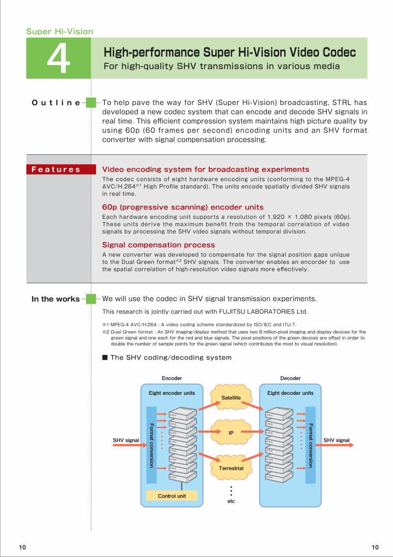
■ The SHV coding/decoding system
※1 MPEG-4 AVC/H.264 : A video coding scheme standardized by ISO/IEC and ITU-T.※2 Dual Green format : An SHV imaging/display method that uses two 8 million-pixel imaging and display devices for the green signal and one each for the red and blue signals. The pixel positions of the green devices are offset in order to double the number of sample points for the green signal (which contributes the most to visual resolution).
SHV signal SHV signal
Satellite
IP
Terrestrial
etc
Encoder
Eight encoder units
Control unit
Decoder
Eight decoder units
Format conversion
Format conversion
10 10

Integral 3D TV
5 Integral Three-dimensional Television Creating more natural three-dimensional images
STRL is researching integral three-dimensional (3D) TV for future broadcasting. The system is based on integral photography※1 and uses lens arrays for capturing and displaying 3D images. We improved the image quality of the displayed 3D image by reducing the position errors of the lens arrays and by compensating for distortion in the projected elemental images.
O u t l i n e
We will enhance the image quality and develop image-processing technologies that will enable us to control apparent depth of the reconstructed images.
This research is jointly carried out with JVC Kenwood Holdings, Inc.
Part of this research is carried out under a project commissioned by the National Institute of Information and Communications Technology.
In the works
3D TV without special glassesIntegral 3D TV does not require special glasses to see 3D images, and viewers can move horizontally and vertically and still see the images.
Super Hi-Vision technologyBy using full-resolution Super Hi-Vision technology, the system can display 3D images having 400 × 250 pixels.
Improvement of image quality STRL researchers reduced the blurriness and spatial distortion of the 3D image by improving lens array production technology and image distortion compensation technology.
F e a t u r e s
■ Integrated 3D TV system
※1 Integral photography: A method of reproducing 3D images that uses miniature lens arrays for image capture and display.
Lens array foimage capture
Lens array forimage display
Depthcontrol lens
Displayed 3D image
Full-resolutionSuper Hi-Vision camera
Full-resolutionSuper Hi-Vision projector
Subject
Screen
(Display system)
(Image capture system)Imagecompensation
process Micro lenses
10 10
Digital Terrestrial Broadcasting
6 Channel Equalizer of Multipath Distortion for Community Reception FacilitiesStable reception of digital terrestrial broadcasts
To ensure stable reception of digital terrestrial broadcasts, STRL is developing reception technology that is resistant to interference. This exhibit presents a new channel equalizer※1 for use in community reception facilities. It reduces the multipath distortion of received signals caused by long-delay multipath waves outside the guard interval (GI※2) of the OFDM※3 signal.
O u t l i n e
We will test the prototype in actual reception environments with long-delay multipath waves outside the guard interval. A successful test will speed the equipment’s early release and widespread use.
In the works
Channel equalizer for community reception facilitiesEqualizing technology for long-delay multipath waves has already been developed for relay stations. We used this technology as a basis for an equalizer that can be used in community reception facilities that have limited installation space and high ambient temperature
Better equalization algorithmThe equalizing algorithm separates the multipath distortion outside the guard interval from the multipath distortion inside the guard interval.
F e a t u r e s
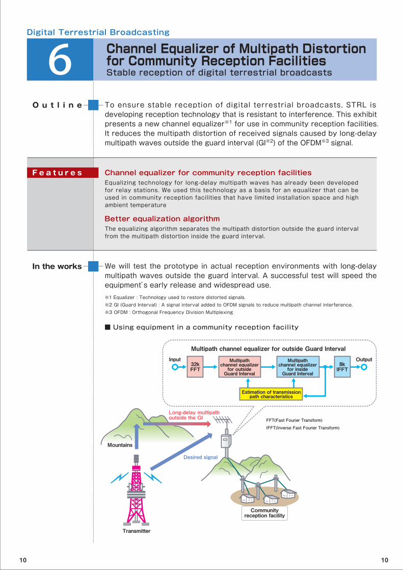
■ Using equipment in a community reception facility
※1 Equalizer : Technology used to restore distorted signals.※2 GI (Guard Interval) : A signal interval added to OFDM signals to reduce multipath channel interference.※3 OFDM : Orthogonal Frequency Division Multiplexing
FFT(Fast Fourier Transform)
IFFT(Inverse Fast Fourier Transform)
Mountains
Multipath channel equalizer for outside Guard Interval
Desired signal
Transmitter
Long-delay multipathoutside the GI
Communityreception facility
32kFFT
8kIFFT
Input OutputMultipathchannel equalizer
for insideGuard Interval
Multipathchannel equalizer
for outsideGuard Interval
Estimation of transmissionpath characteristics
10 10

Digital Terrestrial Broadcasting
7 Interference Canceller for Digital Terrestrial Broadcasting ReceiverStable reception of digital terrestrial broadcasting
A large number of transmitter sites are being installed for digital terrestrial broadcasting, and this means that co-channel interference can occasionally disrupt signal reception. To solve this problem, we have developed a compact, low-cost digital interference canceller for use in community reception facilities and households.
O u t l i n e
We will commercialize this technology as an adaptor for home receivers and community reception facilities.
In the works
Compact, facilitates lower-cost operationThe digital interference canceller receives the input signal with two antennas and synthesizes them by using just one signal synthesis circuit.
Supports poor reception environmentsBecause normal receivers have a function for equalizing channel distortion, the interference canceller only eliminates the interference components and leaves the channel distortion as it is. This feature enables it to operate stably in poor reception environments.
F e a t u r e s
■ Cancelling co-channel interference
Digital relay stationbroadcasting different
programs
Householdinterferencecanceller
Desired signal
Digital interference
Transmittingstation
Household
OFDMdemodulation
OFDMmodulation
Symbolregeneration
Antenna 1 Interference canceller output
Antenna 2
Optimization ofweight coefficients
Transmissionpath
characteristics
OFDM(Orthogonal Frequency Division Multiplexing)
10 10
Digital Terrestrial Broadcasting
8 Mobile Reception Technology for Digital Terrestrial HDTV BroadcastingExpanding the area of mobile reception
Drops in received signal power and obstacles such as buildings limit the areas in which vehicles on the move can receive Hi-Vision broadcasting. This exhibit presents mobile reception technology that uses eight-branch space diversity reception and iterative decoding of error correction codes to let mobile viewers receive Hi-Vision broadcasting over a wider reception area.
O u t l i n e
We will conduct laboratory tests with a transmission simulator and field tests with broadcasting signals. We will verify the unit’s operation characteristics, improve its performance improvements, and study it in different reception environments.
In the works
Eight-branch space-diversity reception technologyThis technology uses eight receiving antennas to synthesize signals in a manner that maximizes the received signal power and reduces distortion. It improves reception of weak signals and compensates for frequency distortion from interference signals.
Iterative decoding technologyNormal ly in d ig i ta l terrestr ia l broadcast ing , the convo lut iona l code※1 and Reed-Solomon code※2 used to correct errors are each decoded once. In contrast, this technology improves error correction performance by decoding them iteratively (multiple times).
F e a t u r e s
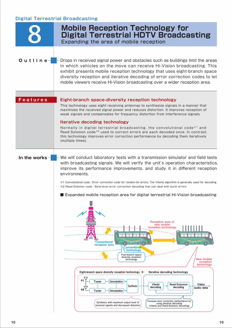
■ Expanded mobile reception area for digital terrestrial Hi-Vision broadcasting
※1 Convolutional code : Error correction code for random bit errors. The Viterbi algorithm is generally used for decoding.※2 Reed-Solomon code : Byte-level error correction decoding that can deal with burst errors
Conventionalreception area
Eight-branch space diversity reception technology Iterative decoding technology
Reception area ofnew mobile
reception technology
New mobilereception
technology
Four-branch spacediversity reception
technology
Synthesis with maximum output level ofreceived signals and decreased distortion
Increase error correction performance byusing iterative decoding
(Viterbi and Reed-Solomon decoding)
TunerReed-Solomon
decodingViterbi
decodingVideo
audio data
Demodulation
Tuner DemodulationSynthesis
#1
#8
+
●●●●●
●●●●●
●●●●●
Conventionaltechnology
10 10
Digital Terrestrial Broadcasting
9 Mobile Multimedia Broadcasting in the VHF-Low BandCreating storable broadcast services for portable devices
In 2009, the Information and Communications Council decided on the format for multimedia broadcasts on channels 1 to 3 in the VHF band (90 to 108 MHz). These channels will be freed up after analog television broadcasts on them end in 2011. This exhibit presents prototype receivers based on this format and illustrates how multimedia broadcast services can be enjoyed by viewers.
O u t l i n e
We will carry out tests to clarify the transmission characteristics of the format and study ways of optimizing it.
The prototype receivers with the services storage function were developed in cooperation with Access Co. Ltd.
In the works
High-quality video/audio servicesThe services will have the current digital sound broadcast format (ISDB-TSB)※1, but wi l l provide high-qual i ty sound and images and be more diversified than the current ”One-Seg“ services. In particular, services will have a video frame rate of up to 30 frames per second and will use the MPEG surround audio compression format.
Receivers that can record broadcast content The receiver is designed to record broadcasts without loss even while on the move. Users will be able to select and view their favorite recorded content at any time. Programs such as news will be updated automatically to the latest content.
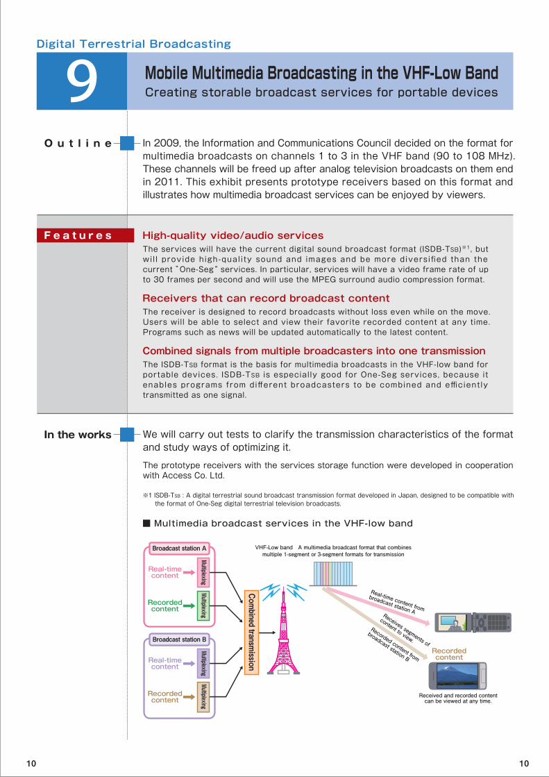
Combined signals from multiple broadcasters into one transmissionThe ISDB-TSB format is the basis for multimedia broadcasts in the VHF-low band for portable devices. ISDB-TSB is especially good for One-Seg services, because it enables programs from different broadcasters to be combined and efficiently transmitted as one signal.
F e a t u r e s
■ Multimedia broadcast services in the VHF-low band
※1 ISDB-TSB : A digital terrestrial sound broadcast transmission format developed in Japan, designed to be compatible with the format of One-Seg digital terrestrial television broadcasts.
Received and recorded contentcan be viewed at any time.
Recorded content from
broadcast station B
Real-time content from
broadcast station AReceives segments of
content to view.
VHF-Low band A multimedia broadcast format that combinesmultiple 1-segment or 3-segment formats for transmission
Real-timecontent
Broadcast station A
Recordedcontent
Real-timecontent
Broadcast station B
Recordedcontent
Recordedcontent
Multiplexing
Combined transm
ission
MultiplexingMultiplexing
Multiplexing
10 10
Digital Terrestrial Broadcasting
10 Large-capacity Transmission Technology for Next-generation Digital Terrestrial BroadcastingCreating Super Hi-Vision digital terrestrial broadcasts
STRL is researching ways of expanding transmission capacities to enable Super Hi-Vision and other large-capacity content to be carried over digital terrestrial broadcasts. By using ultra-multilevel OFDM※1 technology and dual polarized MIMO※2 technology, we can transmit four Hi-Vision programs on a single channel.
O u t l i n e
We will continue a wide range of research to find new ways of expanding transmission capacities and provide stable, high-quality services. Our goal is to achieve the ultimate in next-generation digital terrestrial broadcasts.
In the works
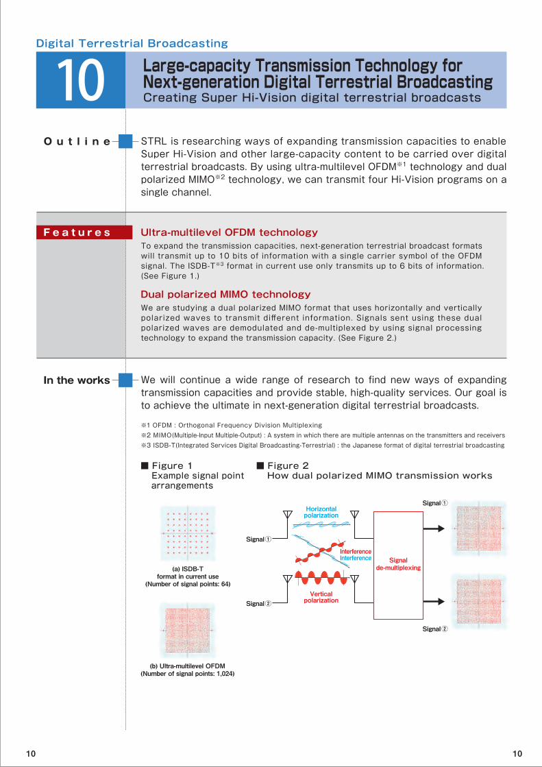
Ultra-multilevel OFDM technologyTo expand the transmission capacities, next-generation terrestrial broadcast formats will transmit up to 10 bits of information with a single carrier symbol of the OFDM signal. The ISDB-T※3 format in current use only transmits up to 6 bits of information. (See Figure 1.)
Dual polarized MIMO technologyWe are studying a dual polarized MIMO format that uses horizontally and vertically polarized waves to transmit different information. Signals sent using these dual polarized waves are demodulated and de-multiplexed by using signal processing technology to expand the transmission capacity. (See Figure 2.)
F e a t u r e s
■ Figure 1 Example signal point arrangements
■ Figure 2 How dual polarized MIMO transmission works
※1 OFDM : Orthogonal Frequency Division Multiplexing※2 MIMO(Multiple-Input Multiple-Output) : A system in which there are multiple antennas on the transmitters and receivers ※3 ISDB-T(Integrated Services Digital Broadcasting-Terrestrial) : the Japanese format of digital terrestrial broadcasting
Signal①
(a) ISDB-Tformat in current use
(Number of signal points: 64)
(b) Ultra-multilevel OFDM(Number of signal points: 1,024)
Signal②
Signal②
Signal①
Signalde-multiplexing
Verticalpolarization
InterferenceInterference
Horizontalpolarization
10 10
Digital Terrestrial Broadcasting
11 Robust Transmission Technology of Mobile Reception for Next-generation Digital Terrestrial BroadcastingMaking Hi-Vision transmissions possible even in poor reception environments
The next generation of digital terrestrial broadcasting will be able to transmit Hi-Vision and high-resolution images to mobile phones and receivers. This exhibit introduces some of the transmission technologies that can work in multipath fading environments.
O u t l i n e
We are testing prototype equipment in the lab and in the field, and we are continuing to study transmission technologies for mobile reception of high-quality broadcast services such as Hi-Vision.
In the works
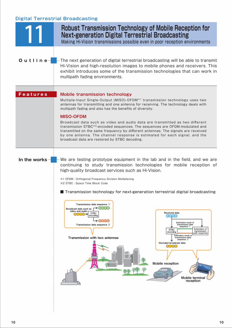
Mobile transmission technologyMultiple-Input Single-Output (MISO)-OFDM※1 transmission technology uses two antennas for transmitting and one antenna for receiving. The technology deals with multipath fading and also has the benefits of diversity.
MISO-OFDMBroadcast data such as video and audio data are transmitted as two different transmission STBC※2-encoded sequences. The sequences are OFDM-modulated and transmitted on the same frequency by different antennas. The signals are received by one antenna. The channel response is est imated for each signal , and the broadcast data are restored by STBC decoding.
F e a t u r e s
■ Transmission technology for next-generation terrestrial digital broadcasting
※1 OFDM : Orthogonal Frequency Division Multiplexing※2 STBC : Space Time Block Code
Mobile reception
Transmission data sequence ①
Estimation result oftransmission data
sequence ①
Estimation result oftransmission data
sequence ②Transmission with two antennas
Broadcast data such asvideo and audio
Received data
Transmission data sequence ②
Mobile terminalreception
STBCencoding
STBCencoding
Estimation oftransmissionpath response
Decoded broadcast data
10 10

BS analog broadcast
BS digital broadcast
Digital Terrestrial Broadcasting
12 Consultation Desk for Answering Your Questions about Digital Broadcasting ReceptionResolving difficulties in receiving digital broadcasting
Analog terrestrial and satellite TV broadcasts will end untill July 24 2011 and be completely replaced by digital broadcasting. NHK is working to keep users informed about the problems they may encounter in receiving digital broadcasts. The consultation desk is here to offer solutions to your problems and respond to your questions about digital broadcasting.
O u t l i n e
NHK is making an all-out effort to enable a smooth end to analog broadcasts and transition to digital broadcasts. It is working with organizations such as the DTV Support Center of the Ministry of Internal Affairs and Communications and local electronics stores.
In the works
Providing information for reception digital broadcastsWith just about a year until analog broadcasts end, we are stepping up our campaign to inform people in Japan about the end of analog TV and how to receive digital broadcasts.
Receiving digital terrestrial broadcasts in urban areasMost areas that have been able to receive analog broadcasts with individual antennas will be able to receive digital broadcasts. Most community reception facilities designed to combat signal interference from buildings and power lines will also be able to receive digital broadcasts.
Digital terrestrial broadcasts from Tokyo Sky TreeWhen the transmission point of origin changes to the Tokyo Sky Tree from 2012 on, homes and facilities with antennas oriented toward Tokyo Tower should still be able to receive broadcasts without altering the antenna direction.
F e a t u r e s
Digital terrestrialbroadcasting
Digital relay stationApproximately 2,100 stationsconstructed throughout Japan
CATV
Master station(such as Tokyo Tower)
Sky TreeWill be completed in 2011and start operation in 2012.
Will end July 24, 2011
Receiveddirectly
Communityreception facility (apartment buildings)
Community reception facility(Facility designed to combat
reception interference)
Cable TV
Community reception facility
Broadcast satelliteChangeover
10 10

Super Hi-Vision
13 Super Hi-Vision TheaterExperience firsthand ultra-high-definition video and immersive sound
Here, you can view a Super Hi-Vision (SHV) program shot with a prototype camera designed to be compact and easily handled. The 22.2 multichannel sound system produces immersive and natural three-dimensional sound. You can also experience SHV video filmed with a full-resolution SHV camera.
O u t l i n e
The full-resolution SHV video devices and efficient production system will help us to conduct basic research on human perception※2 and study systematic approaches to determining the full-spec※3 SHV parameters and international standards.
In the works
Advanced SHV program production technologyWe reduced the size and improved the operation characteristics of the Dual Green format※1 SHV camera to make it more mobile and made the 22.2 multichannel sound production system more efficient.
Full-resolution SHV devices in developmentWe are working on the cameras, recorders, and other devices needed to produce full-resolution SHV programs.
Creating international standardsITU-R has started discussions on creating international standards for SHV video and multichannel audio.
F e a t u r e s
■ SHV parameters
Image
・ Scanning format : 60 frames per second, progressive scanning ・ Screen aspect ratio : 9:16 ・ Design viewing distance : 0.75 x screen height ・ Horizontal viewing angle : 100°
Sound
・ 22.2 multichannel sound
0.75 xscreen height
Horizontal viewingangle of 100°
7680pixels
4320pixels
※1 Dual Green format : An SHV imaging/display method that uses two 8 million-pixel imaging and display devices for the green signal and one each for the red and blue signals. The pixel positions of the green devices are offset in order to double the number of sample points for the green signal (which contributes the most to visual resolution).※2 Human perception characteristics : Psychological and physiological reactions resulting from stimulation of visual and audio senses. ※3 Full-spec : Specifications of all video parameters Suitable for Super Hi-Vision
10 10

Museum of Broadcasting
14 Eighty Years of STRL AchievementsNHK Museum of Broadcasting
The Science & Technology Research Laboratories (STRL) opened in June 1930 with a staff of just sixteen researchers. The following year, the fledgling laboratory purchased a mechanical television (televisor) developed in the UK and started researching this new medium. By 1939, it was giving public demonstrations of television. STRL has since worked over the past eighty years on advancing television technology - from color TV to satellite and Hi-Vision broadcasting.This exhibit highlights STRL’s work on developing television cameras and shows how cameras have evolved. Starting with the iconoscope camera, continuous research and development of camera tubes and other equipment have led to higher quality and more compact models. This exhibit shows some of the cameras and camera tubes that were used for many years.
O u t l i n e
History of STRL’s R&D
STRL established in Kinuta in Setagaya, Tokyo
First public demonstration of television
NHK1-type black and white camera : First camera made in Japan
Research on magnetic recording (VTR) starts.
TKO-3-type IO camera developed : Studio-standard camera
NHK1-type 3IO color camera completed: First color camera made in Japan
Research on high-definition television (HDTV) starts.
Broadcast satellite research starts.
Plasma display (PDP) research starts.
New camera tube developed (Saticon).
One-inch tape VTR prototype created for high-definition television.
MUSE format developed.
HARP camera tube invented.
Start of regular satellite broadcasts.
Digital VTR (D-3VTR) developed.
Research on Super Hi-Vision starts.
Release of international Hi-Vision studio standard.
Hi-Vision BS digital broadcasts start.
New STRL research complex completed.
Super Hi-Vision demonstrated to the public.
1930
1939
1953
1956
1958
1964
1966
1971
1972
1981
1984
1987
1989
1991
1995
2000
2002
Year
10 10
Human-friendly Broadcasting Services
15 Multi-modal Information Presentation System for the Visually Impaired See, hear, and touch digital broadcasts
STRL is are researching barrier-free information technology that will give visually impaired persons access to data broadcasts and electronic program guides of digital broadcasting. This exhibit presents a mult i -modal information presentation system that lets the user select the information format to compensate for any impairment he or she may have.
O u t l i n e
Our goal is to create a practical TV information presentation system for the visually impaired and a multisensory interface to convey information such as menu screens, tables and diagrams by touch.
Part of this research was carried out in cooperation with the University of Tokyo under a project commissioned by the National Institute of Information and Communications Technology.
In the works
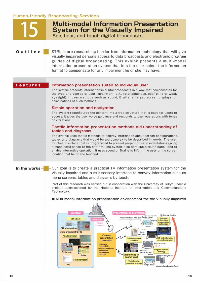
Information presentation suited to individual userThe system presents information in digital broadcasts in a way that compensates for the type and degree of user impairment (e.g., total blindness, deaf-blind or weak eyesight). It uses methods such as sound, Braille, enlarged screen displays, or combinations of such methods.
Simple operation and navigationThe system reconfigures the content into a tree structure that is easy for users to access. It gives the user voice guidance and responds to user operations with tones or vibrations.
Tactile information presentation methods aid understanding of tables and diagramsThe system uses tactile methods to convey information about screen configurations, tables and diagrams that would be too complex to be described in words. The user touches a surface that is programmed to present projections and indentations giving a meaningful sense of the content. The system also acts like a touch panel, and to enable interactive operation, it uses sound or Braille to inform the user of the screen location that he or she touched.
F e a t u r e s
■ Multimodal information presentation environment for the visually impaired
3D object
Digitalbroadcast
Data broadcast/EPG3D information
Visual information
Broadcast
Text information
3D hapticinformationpresentationtechnology
Universal design
Information barrier-free
Tactile operationinterface
Display technology forthe partially sighted
Text informationpresentation technology
2D tactile informationpresentation technology
Navigation assistancetechnology
Diagram/graph
TableGUI menu
Text
Content Presentation of information
Vibrations
Symbolic tones
Tactile stimuli
TableGUI menu
Shape
Rigidity
Enlargedreverse displays
Content presentation conversion
・ Improved accessibility・ Easy-to-understand information
presentation methods Braille
Finger Braille
Voice synthesis
Related exhibit (No. 39)
10 10
Human-friendly Broadcasting Services
16 Translating Japanese into Computer-animated Japanese Sign LanguageExpanding programs with Japanese sign language
To expand the use of Japanese Sign Language (JSL) in broadcasting, STRL is doing basic research on translating Japanese into JSL and automatically generating computer-animated JSL. We recently developed a Japanese-JSL dictionary for use in translating, as well as natural, high-definition computer-animations of JSL.
O u t l i n e
We will develop advanced computer-animated JSL to show facial expressions in addition to hand and finger motions.
This research is jointly carried out with Kogakuin University.
In the works
Japanese-JSL dict ionary that automatically adds new Japanese entriesMaximizing the number of entries in the dictionary should improve translation precision. Our bilingual dictionary automatically registers new Japanese entries, and it has grown to 86,600 entries.
Natural, high-definition computer-animated JSLWe developed a way to display the intricate hand and finger motions used in JSL as computer animations. The animations can be displayed at any angle to make their motions easier to see and to enable their use in JSL learning systems.
F e a t u r e s
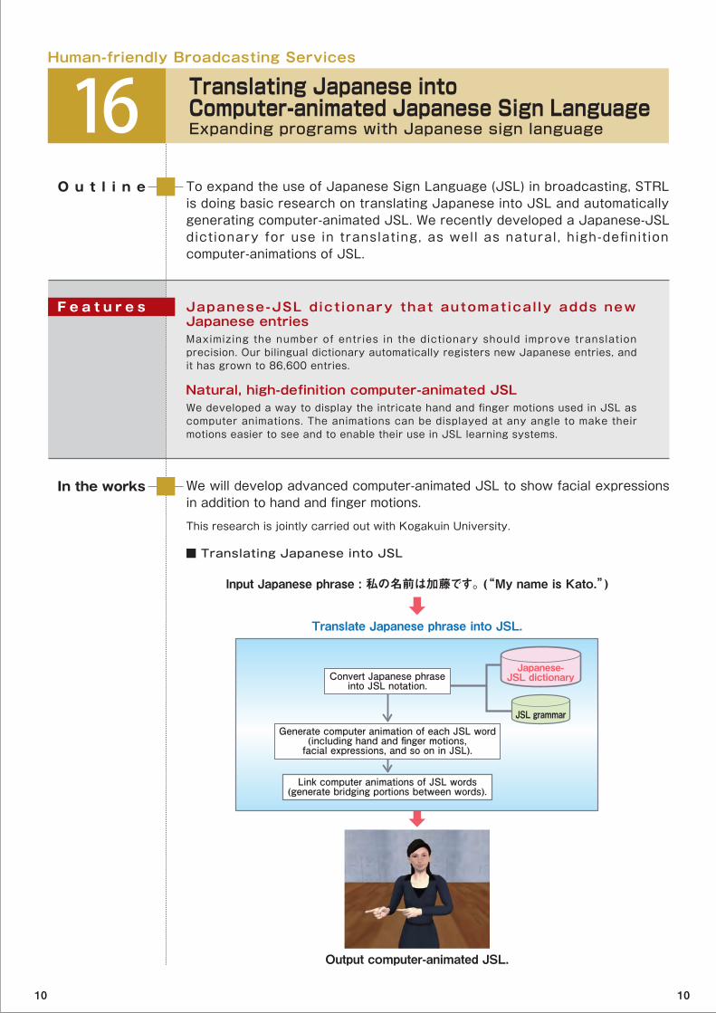
■ Translating Japanese into JSL
Input Japanese phrase : 私の名前は加藤です。 (“My name is Kato.”)
Translate Japanese phrase into JSL.
Output computer-animated JSL.
Japanese-JSL dictionary
JSL grammar
Convert Japanese phraseinto JSL notation.
Generate computer animation of each JSL word(including hand and finger motions,
facial expressions, and so on in JSL).
Link computer animations of JSL words(generate bridging portions between words).
10 10
Human-friendly Broadcasting Services
17 Live Closed-captioning using Speech RecognitionExpanding closed-captioned broadcasts
STRL is researching speech recogni t ion to expand the range of closed-captioned broadcasts and make them accessible to a wider audience including the hearing impaired and elderly. Speech recognition is already used to close-caption sports programs, and STRL has developed a compact, labor-saving system for closed-captioning of news programs.
O u t l i n e
We are aiming for early release of this closed-captioning system for news programs and will increase its speech recognition ability to enable closed-captioning for non-news programs.
In the works
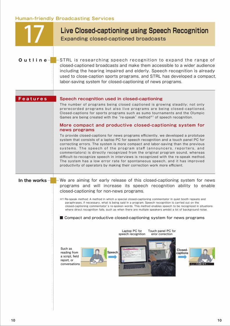
Speech recognition used in closed-captioningThe number of programs being closed captioned is growing steadily; not only prerecorded programs but a lso l ive programs are be ing c losed-capt ioned . Closed-captions for sports programs such as sumo tournaments and the Olympic Games are being created with the “re-speak” method※1 of speech recognition.
More compact and productive closed-captioning system for news programsTo provide closed-captions for news programs efficiently, we developed a prototype system that consists of a laptop PC for speech recognition and a touch panel PC for correcting errors. The system is more compact and labor-saving than the previous sys t ems . The speech o f t he p rog ram s t aff ( announce r s , r epo r t e r s , and commentators) is directly recognized from the original program sound, whereas difficult-to-recognize speech in interviews is recognized with the re-speak method. The system has a low error rate for spontaneous speech, and it has improved productivity of operators by making their correction work more efficient.
※1 Re-speak method: A method in which a special closed-captioning commentator in quiet booth repeats and paraphrases, if necessary, what is being said in a program. Speech recognition is carried out on the closed-captioning commentator’s re-spoken words. This method enables speech to be recognized in situations where direct recognition fails, such as when there are multiple speakers amidst a lot of background noise.
F e a t u r e s
■ Compact and productive closed-captioning system for news programs
Such as reading from a script, field report, or conversations
Laptop PC forspeech recognition
Touch panel PC forerror correction
ニュースを続けます...
SpeechClosed-captions
10 10
Background sound adjustment menu
Human-friendly Broadcasting Services
18 Automatic Evaluation of Program Sound Balance for the ElderlyCreating Program Sound That Is Easy to Listen to by Anyone
STRL’s goal is to make broadcasts services easier for the elderly to listen to. It conducted subjective evaluations of program audio and developed a technology that automatically determines the optimal sound balance for elderly persons from the relationship between the loudnesses of the narration and background sound (music and sound effects). The exhibit introduces research results and gives a sound demonstration.
O u t l i n e
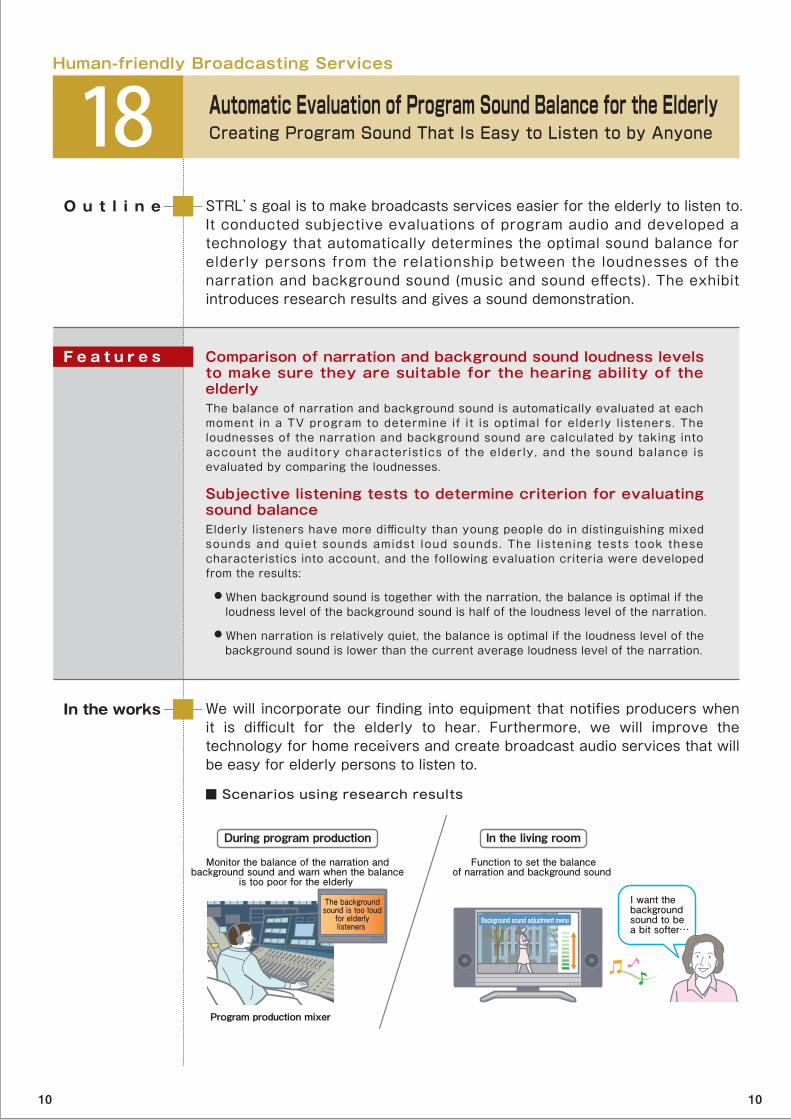
We will incorporate our finding into equipment that notifies producers when it is difficult for the elderly to hear. Furthermore, we will improve the technology for home receivers and create broadcast audio services that will be easy for elderly persons to listen to.
In the works
Comparison of narration and background sound loudness levels to make sure they are suitable for the hearing ability of the elderlyThe balance of narration and background sound is automatically evaluated at each moment in a TV program to determine if it is optimal for elderly l isteners. The loudnesses of the narration and background sound are calculated by taking into account the auditory characteristics of the elderly, and the sound balance is evaluated by comparing the loudnesses.
Subjective listening tests to determine criterion for evaluating sound balance Elderly listeners have more difficulty than young people do in distinguishing mixed sounds and quiet sounds amidst loud sounds. The l istening tests took these characteristics into account, and the following evaluation criteria were developed from the results:
● When background sound is together with the narration, the balance is optimal if the loudness level of the background sound is half of the loudness level of the narration.
● When narration is relatively quiet, the balance is optimal if the loudness level of the background sound is lower than the current average loudness level of the narration.
F e a t u r e s
■ Scenarios using research results
I want thebackgroundsound to bea bit softer…
Monitor the balance of the narration andbackground sound and warn when the balance
is too poor for the elderly
During program production
Function to set the balanceof narration and background sound
In the living room
Program production mixer
The backgroundsound is too loud
for elderlylisteners
10 10
Human-friendly Broadcasting Services
19 Automatic Detection of Unpleasant ScenesMaking Scenes Pleasant for Viewing
Viewers may feel a sense of unpleasantness from onscreen shaking and flickering, a problem with large-screen TVs. STRL is developing a way of au tomat ica l l y de tec t i ng scenes tha t p roduce such a sense o f unpleasantness so that they can be revised during production.
O u t l i n e
We will create prototype equipment that will automatically detect unpleasant scenes. Furthermore, we plan to create systems that will automatically suppress the sense of unpleasantness in a scene.
In the works
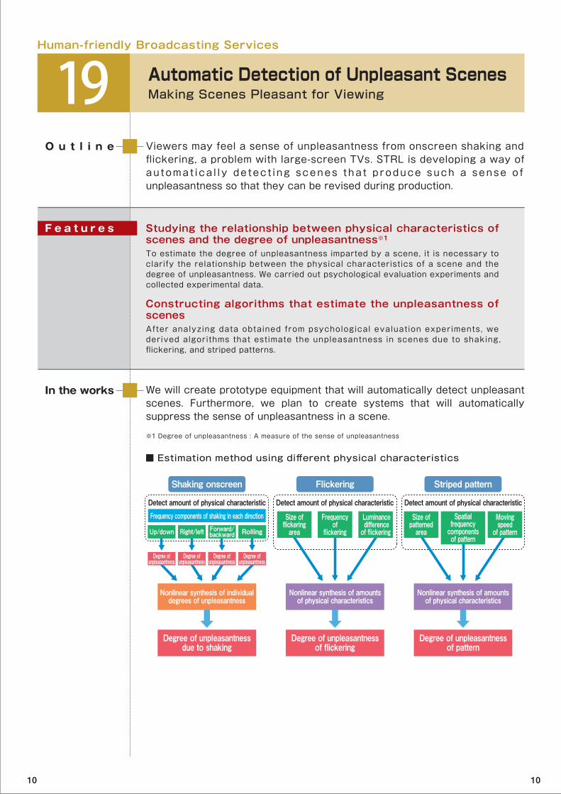
Studying the relationship between physical characteristics of scenes and the degree of unpleasantness※1To estimate the degree of unpleasantness imparted by a scene, it is necessary to clarify the relationship between the physical characteristics of a scene and the degree of unpleasantness. We carried out psychological evaluation experiments and collected experimental data.
Constructing algorithms that estimate the unpleasantness of scenesAfter analyzing data obtained from psychological evaluation experiments, we derived algorithms that estimate the unpleasantness in scenes due to shaking, flickering, and striped patterns.
F e a t u r e s
■ Estimation method using different physical characteristics
※1 Degree of unpleasantness : A measure of the sense of unpleasantness
Degree of unpleasantnessdue to shaking
Shaking onscreen
Frequency components of shaking in each directionDetect amount of physical characteristic Detect amount of physical characteristic Detect amount of physical characteristic
Nonlinear synthesis of individualdegrees of unpleasantness
Up/down Right/left Forward/backward Rolling
Degree ofunpleasantness
Degree of unpleasantnessof flickering
Flickering
Nonlinear synthesis of amountsof physical characteristics
Size offlickeringarea
Luminancedifference
of flickering
Frequencyof
flickering
Size ofpatterned
area
Movingspeed
of pattern
Spatialfrequency
componentsof pattern
Degree of unpleasantnessof pattern
Striped pattern
Nonlinear synthesis of amountsof physical characteristics
Degree ofunpleasantness
Degree ofunpleasantness
Degree ofunpleasantness
10 10

STRL is proceeding in its research on Super Hi-Vision broadcasting for cable television. It has developed technologies that transmit SHV on existing cable television systems by dividing encoded SHV signals, which are greater in size than the encoded Hi-Vision signals, and transmitting them on radio frequency channels.
O u t l i n e
Besides coax cable television, we are developing cable television for optical access networks for transmitting SHV signals multiplexed in the time domain.
In the works
SHV transmission using multiple 256-QAM※1 signalsTo enable SHV transmission on existing cable television systems, the encoded SHV program (about 146 Mbps at exhibitions) is divided into four signals. Each signal is transmitted using a 256-QAM signal with a 6 MHz bandwidth.
Multiplexing that efficiently uses transmission channelsWe have developed a multiplexing method suitable for simultaneous transmission of a variety of programs of different capacities, such as SHV and Hi-Vision, on cable television. More programs can be sent in a limited number of transmission channels, and each program can be transmitted in as few transmission channels as possible. This reduces of the number of tuning circuits in the receiver and lowers power consumption.
F e a t u r e s
■ Transmission of encoded SHV signals using multiple carrier waves
Super Hi-Vision
※1 QAM(Quadrature Amplitude Modulation) : A digital modulation scheme that includes the amplitude and phase of the carrier as information
Re-transmissionfacility (head end)
Coaxial cabletransmission
path
Home
Composition
EncodedSHV signals SHV
Hi-Visionbroadcasting
signal
Hi-Vision
20 Cable Television System for Super Hi-VisionFor Forthcoming High-Capacity Broadcasting Services
Division
ModulationModulationModulationModulation
DemodulationDemodulationDemodulationDemodulation
10 10
21 Optical LAN for Super Hi-VisionTransmitting More than One Channel on a Single Optical Fiber
STRL is researching ultra-fast optical networks for transmitting Super Hi-vision signals between studios, video servers, editing rooms, etc. in a broadcasting center. STRL made a prototype network that can transmit multi-channel uncompressed Super Hi-Vision signals (Dual Green format※1) over a single optical fiber.
O u t l i n e
Our eventual goal is to create ultra-high-speed optical networks that can transmit multi-channel full-resolution Super Hi-Vision signals whose bit rate is 72 Gbps.
This research is jointly carried out with the National Institute of Advanced Industrial Science and Technology and the Photonics Electronics Technology Research Association.
Part of this research is carried out under a project commissioned by the New Energy and Industrial Technology Development Organization.
In the works
Error correction for stable transmissionAt the transmitter, each uncompressed Super Hi-Vision signal consisting of 16 HD-SDI (High-Definition Serial Digital Interface) signals, whose total bit rate is 24 Gbps, is converted into a 40-Gbps optical signal including error correction codes. Because the receiver can correct errors caused by noise and distortion in the transmission path, the Super Hi-Vision signals can be transmitted stably.
160-Gbps ultra-high-speed transmission using optical time division multiplexing (OTDM)※2 By carrying out OTDM on up to four streams of 40-Gbps optical signals, we can transmit up to four channels of studio-quality Super Hi-Vision signals on a single optical fiber with low latency.
F e a t u r e s
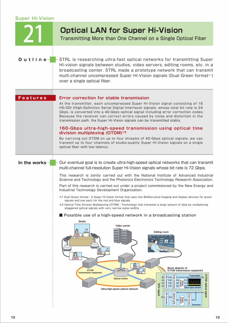
■ Possible use of a high-speed network in a broadcasting station
Super Hi-Vision
※1 Dual Green format : A Super Hi-Vision format that uses two 8million-pixel imaging and display devices for green signals and one each for the red and blue signals. ※2 Optical Time Division Multiplexing (OTDM) : Technology that transmits a large amount of data by multiplexing staggered optical signals with very narrow pulse widths.
OTDMtransmission equipment
Optical switch
Ultra-high-speed optical network
Studio
Editing room
Video server
OTDM optical signal
SHV signal
Receiver
Transmitter
Block diagram of OTDM transmission equipment
Optical signal waveform
40G Conversion40G Conversion
Optical gate
Clock recovery
Delay
controlDelay
control
Pulse shortening
10 10
22 Lightweight Loudspeaker using Polymer FilmsLightweight 3D Structures for Improved Sound Quality
STRL’s goal is to make the 22.2 multichannel sound system for Super Hi-Vision practical for homes, and to this end, it is conducting research on compact and lightweight loudspeakers. STRL invented a completely new type of loudspeaker that utilizes electroactive elastomer※1, and it improved its frequency response and sound quality.
O u t l i n e
We seek to develop thinner loudspeakers with a wide dynamic range that can be freely placed in the home. We will make the form more compact and lower the driving voltage.
This research is jointly carried out with Foster Electric Company.
In the works
Enlarged frequency responseBy using a push-pull※2 structure and optimizing the driver, we made it possible for just a single loudspeaker unit to have a wide frequency range (from 80 Hz to 15 kHz).
Reducing drive voltageThe push-pull structure maintains the tensile strength of the electroactive elastomer in sheet form and can make use of a very thin elastomer. The required driving voltage is lowered as a result.
Loudspeakers in various formsBecause the material is flexible and lightweight, it can be shaped into various forms. The size can also be freely chosen.
F e a t u r e s
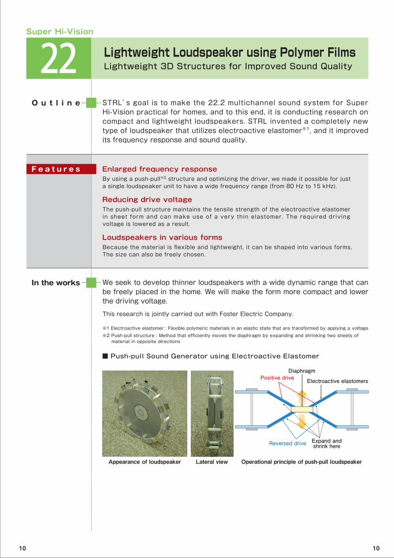
■ Push-pull Sound Generator using Electroactive Elastomer
Super Hi-Vision
※1 Electroactive elastomer : Flexible polymeric materials in an elastic state that are transformed by applying a voltage※2 Push-pull structure : Method that efficiently moves the diaphragm by expanding and shrinking two sheets of material in opposite directions
Appearance of loudspeaker Lateral view
Electroactive elastomers
Diaphragm
Operational principle of push-pull loudspeaker
Expand andshrink here
Positive drive
Reversed drive
10 10

23 58-inch Diagonal Ultrahigh-Definition Plasma Display with 0.33-mm Pixel PitchSuper Hi-Vision for Home Use
STRL is are developing large ultrahigh-definition plasma display panels (PDPs) to show Super Hi-Vision television programs. STRL conducted gas-discharge simulations※1 and PDP panel simulations※2 and used the results to create a 58-inch ultrahigh-resolution prototype with a 0.33-mm pixel pitch.
O u t l i n e
We will proceed with the development of 100-inch class ultrahigh-definition panels. We will also develop high-speed drive technologies and find ways to lower the power consumption of such displays.
This research is jointly carried out with Panasonic.
In the works
Optimization of gas conditions for micro cellsWe drew up guidelines for the optimizing the gas condit ions of micro cells by comprehensively evaluating the luminance efficiency, variation in brightness, and stability of displays for different amounts of xenon in the gas mixture.
Mid-sized panel with the smallest pixel pitch everThe PDP prototype has 3,840 pixels in the horizontal direction and 2,160 pixels in the vertical direction and has a 0.33 mm pixel pitch.
F e a t u r e s
■ Development of 58-inch 0.33-mm pixel pitch ultrahigh-definition PDP
Super Hi-Vision
※1 Gas-discharge simulation : Simulation of gas-discharge phenomenon within a unit cell, including drift of electrons and collisions of atoms and ultraviolet emissions, to obtain the luminescence properties of a cell※2 PDP panel simulation : Simulation that analyzes electric circuits including discharge cells to study in the uniformity of a PDP’s brightness and driving voltage (gas-discharge variability)
Developed in 2009 Developed in 2010
58-inch diagonalPixel pitch : 0.33 mm
Gas-discharge simulation(Analysis of luminescence properties
of the discharge of a unit cell)
PDP panel simulation(Analysis of gas-discharge variation)
Increasing efficiency of micro cells
103-inch diagonalPixel pitch : 0.59 mm
10 10
Proposed
HDTV(ITU-R Recommendation BT.709)
Digital cinema(SMPTE RP431-2)
Adobe RGB
x
0.8
0.7
0.6
0.5
0.4
0.3
0.2
0.1
0
y
0 0.1 0.2 0.3 0.4 0.5 0.6 0.7 0.8
R
G
B
24 Wide-gamut Colorimetry for Super Hi-VisionMore Vivid and Accurate Color Reproduction
To ensure that Super Hi-Vision (SHV) broadcasting will convey an unparalleled sense of quality and realism, STRL believes that SHV should have a wide color gamut with more vivid colors than conventional TV can produce.
O u t l i n e
We will continue with our work to standardize Super Hi-Vision video parameters and develop full-spec※4 cameras, displays, and other equipment.
Part of this research is jointly carried out with Mitsubishi Electric Corporation..
In the works
Using monochromatic RGB primaries on spectrum locus※1We favor a new colorimetry※2 that uses monochromatic RGB primaries on the spectrum locus. Such primaries can be obtained from laser light sources.
Covering the color gamuts of existing video systemsThe color gamut we propose completely covers those of Hi-Vision (HDTV), Digital Cinema, and the de facto standard for electronic video (Adobe RGB).
Reproducing almost all real object colors Our color gamut covers 99.9% of the gamut of Pointer's colors※3, a gamut that represents real surface colors.
F e a t u r e s
■ RGB primaries of Super Hi-Vision and Pointer’s colors (x-y chromaticity diagram)
Super Hi-Vision
※1 Spectrum locus : Curve on a chromaticity diagram that expresses all colors with different wavelengths of monochromatic visible colors. ※2 Colorimetry : A scheme that quantitatively represents colors ※3 Pointer’s color : Data that show the color gamut of real surface colors※4 Full-spec : Specifications of all video parameters suitable for Super Hi-Vision
10 10
25 Home Reproduction of Super Hi-Vision Audio22.2 Multichannel Sound from a Few Loudspeakers
The Super Hi-Vision (SHV) features 22.2 multichannel sound※1. However, such a large number of speakers is not practical in the average home environment; it will be necessary to use as few loudspeakers as possible to reproduce such highly realistic audio. By calculating the propagation characteristics of sound in listening area, 22.2 multichannel sound could be reproduced with four or nine loudspeakers.
O u t l i n e
We are developing a variety of audio signal processing technologies so that 22.2 multichannel sound for Super Hi-Vision can be fully enjoyed in the average home environment.
In the works
Transaural reproduction technologyThe hearing impression of 22.2 multichannel (22.2ch) sound can be determined from the propagation characteristics from the 22.2ch system’s loudspeakers to the left and right ears of a listener. The exhibit is of 22.2ch sound from three loudspeakers and a low frequency effects speaker (3.1ch).
Technology for conversion of the number of audio channelsWe can use information about the placement of loudspeakers inside homes to convert signals of the original sound system into those of another system with fewer audio channels while at the same time maintaining the sound pressure level and incident direction of sound at the listening position. This exhibit is of 22.2ch sound from eight loudspeakers and one low frequency effects speaker (8.1ch).
※1 22.2 Multichannel sound : Sound system with 22 audio channels and two channels for low frequency effects.
F e a t u r e s
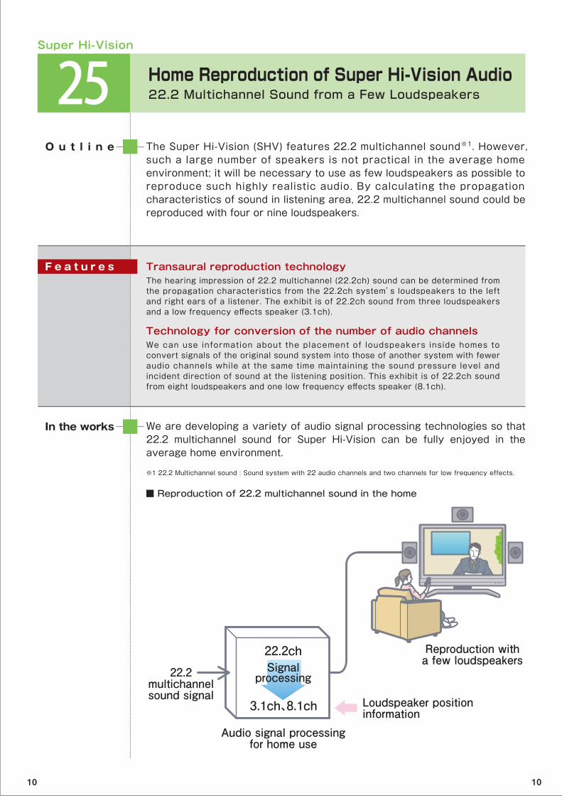
■ Reproduction of 22.2 multichannel sound in the home
Super Hi-Vision
Audio signal processingfor home use
Reproduction witha few loudspeakers
Loudspeaker positioninformation
22.2ch
22.2multichannelsound signal
3.1ch、8.1ch
Signalprocessing
10 10
26 22.2 Multichannel Sound Production System One-point Microphone and 3D Audio Mixing System
STRL is developing sound production systems that can efficiently produce 22.2 multichannel sound for Super Hi-Vision. It greatly expanded the possibilities of 22.2ch sound production by developing new microphones and an audio mixer.
O u t l i n e
We are proceeding to develop 22.2 multichannel sound production equipment, including compact directional microphones and processors to create complex sound effects.
In the works
3D sound image We developed an audio mixing system with a three-dimensional sound panning function that can put sound images at arbitrary positions in 3-D space. Elemental sounds from any direction can be mixed.
Integrated microphone Recording sessions of 22.2 multichannel sound have entailed a great deal of work in sett ing up many microphones. To make i t easier to capture sound for a l ive broadcast, we developed a microphone that can capture sound from all directions.
Mixing of more than 1000 sound elementsSuper Hi-Vision sound is made up of a variety of sound elements, such as natural sounds recorded in the field, music, and sound effects. We developed an audio mixing system that can simultaneously combine more than 1000 sound elements.
F e a t u r e s
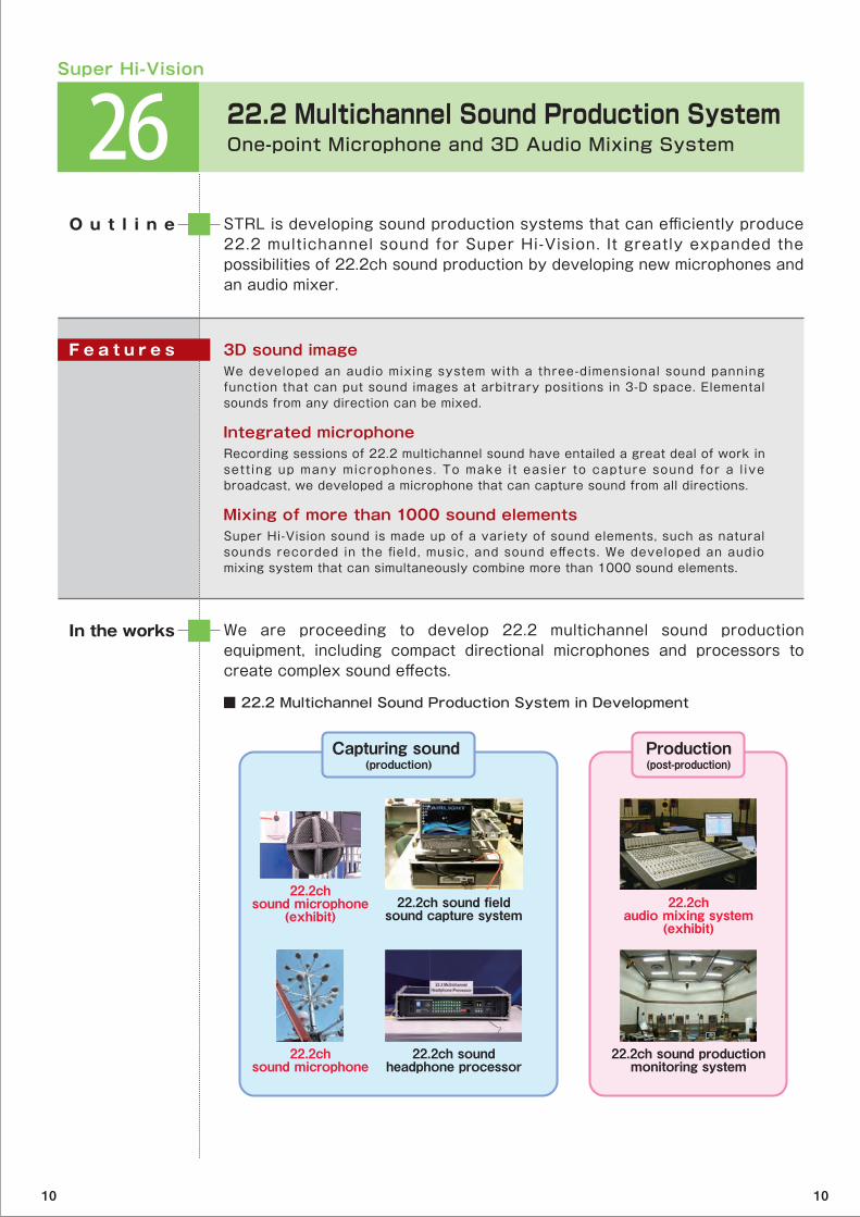
■ 22.2 Multichannel Sound Production System in Development
Super Hi-Vision
Capturing sound (production)
22.2chsound microphone
(exhibit)22.2ch sound field
sound capture system
22.2ch soundheadphone processor
22.2chsound microphone
Production(post-production)
22.2chaudio mixing system
(exhibit)
22.2ch sound productionmonitoring system
10 10

27 Identity-Web Services Framework between Broadcasting and Communication ServicesEnabling Viewers to access various services from their TV
Identity federation makes it easier for people to receive Internet services. STRL developed a framework that anyone watching a TV program to receive communications services.
O u t l i n e
We are proceeding with our research to commercialize Identity Web Services for the new era of integrated broadcasting and communications. We will do this by popularizing our Identity Web Services Framework for services to share their attribute information.
Part of this search is jointly carried out with the Tokyo Institute of Technology.
In the works
Private information for providing communications services can be securely viewed while watching TVWe made it possible for user identity federation to be carried out without the chance of leaks occurring between broadcast services and other services. With just a single sign-on, the user can securely view private information from multiple services on the data broadcast screen.
Making a TV show information from other services The Identity Web Services Framework (ID-WSF) makes it possible for the home TV to notify customers of important messages from any of the services they receive.
F e a t u r e s
■ Scenario of using Identity Web Services Framework
Fusion of Broadcasting and Communications
NHK membership service
Identity Provider
External services for individuals
Taro Kinuta’se-medical chart
Welcome, Mr. Taro KinutaYour pension amount is …
Taro Kinuta’spension information
New productinformation fo
registered customersNetwork
Network for use of multiple individualservices using ID federation technologies
10 10
28 Secure Content Distribution ServicesAnonymity Preserving Signature Scheme for Membership Verification
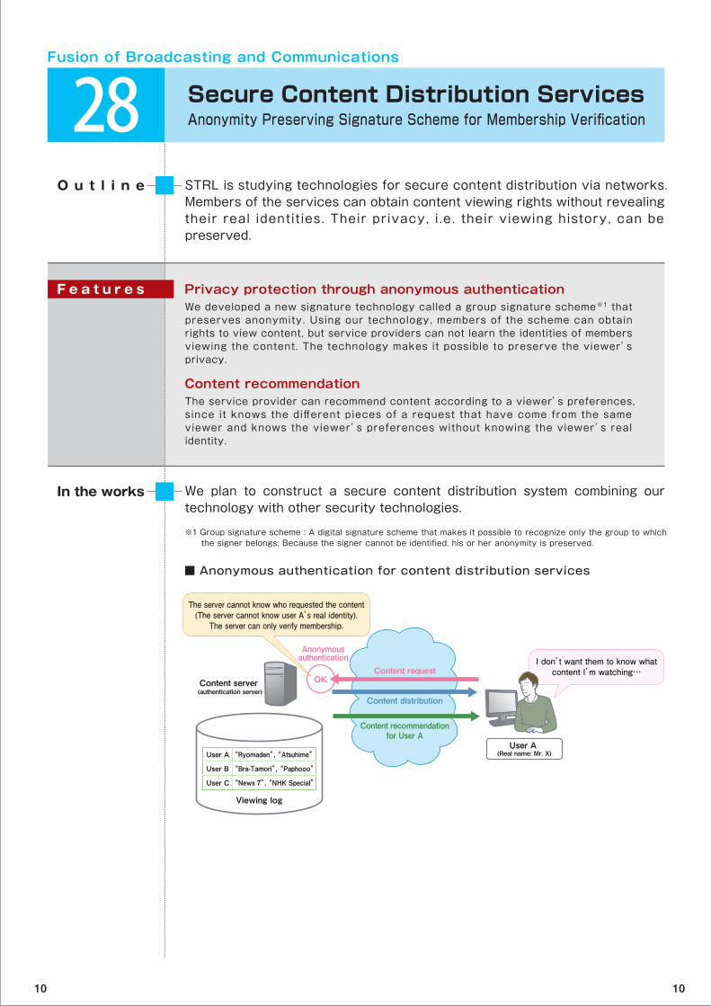
STRL is studying technologies for secure content distribution via networks. Members of the services can obtain content viewing rights without revealing their real identities. Their privacy, i .e. their viewing history, can be preserved.
O u t l i n e
We plan to construct a secure content distribution system combining our technology with other security technologies.
In the works
Privacy protection through anonymous authenticationWe developed a new signature technology called a group signature scheme※1 that preserves anonymity. Using our technology, members of the scheme can obtain rights to view content, but service providers can not learn the identities of members viewing the content. The technology makes it possible to preserve the viewer’s privacy.
Content recommendationThe service provider can recommend content according to a viewer’s preferences, since it knows the different pieces of a request that have come from the same viewer and knows the viewer’s preferences without knowing the viewer’s real identity.
F e a t u r e s
■ Anonymous authentication for content distribution services
Fusion of Broadcasting and Communications
※1 Group signature scheme : A digital signature scheme that makes it possible to recognize only the group to which the signer belongs. Because the signer cannot be identified, his or her anonymity is preserved.
I don’t want them to know whatcontent I’m watching…
Content server (authentication server)
Anonymousauthentication
OK
User A (Real name: Mr. X)
Content distribution
Content request
Content recommendationfor User A
The server cannot know who requested the content(The server cannot know user A’s real identity).
The server can only verify membership.
User A
User B
User C
“Ryomaden”, “Atsuhime”
“Bra-Tamori”, “Paphooo”
“News 7”, “NHK Special”
Viewing log
10 10
29 Digital Watermarking System for Content Distribution over the InternetProtecting Content Copyright
To prevent copyright infringements such as unauthorized distribution of content, STRL is conducting research on digital watermarking technology that embeds invisible information in video. The exhibit demonstrates its technology that quickly detects information embedded in live video streams sent over the Internet.
O u t l i n e
We will improve the watermarking’s resistance to video compression and develop practical ways to apply watermarking to TV programs distributed through a variety of media.
This research is jointly carried out with Mitsubishi Electric Corporation.
In the works
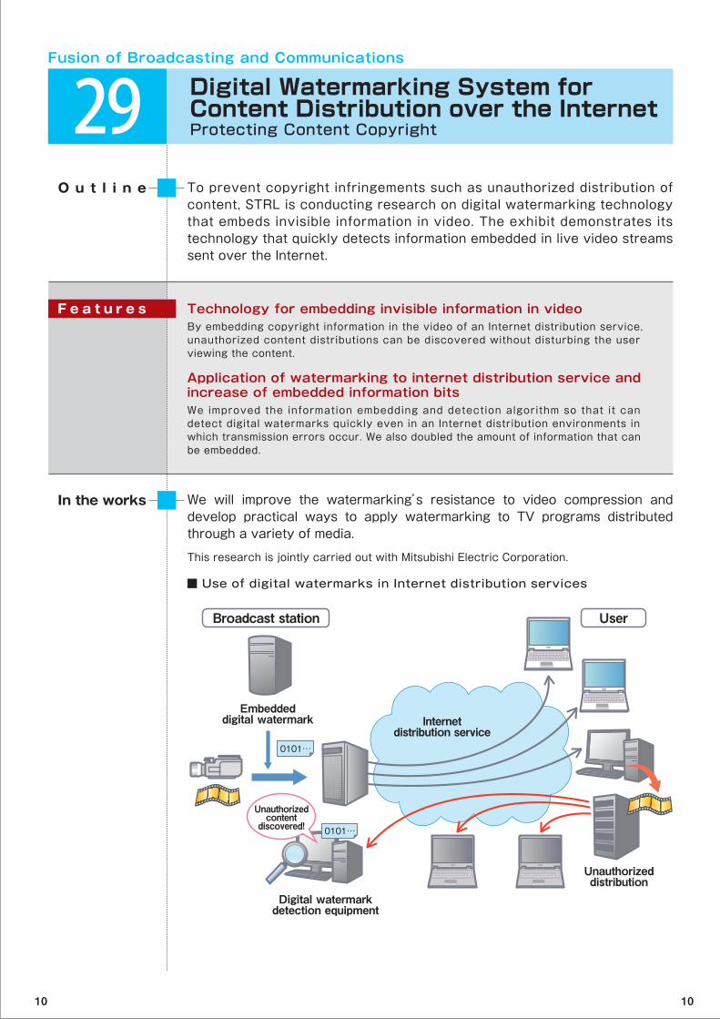
Technology for embedding invisible information in videoBy embedding copyright information in the video of an Internet distribution service, unauthorized content distributions can be discovered without disturbing the user viewing the content.
Application of watermarking to internet distribution service and increase of embedded information bitsWe improved the information embedding and detection algorithm so that it can detect digital watermarks quickly even in an Internet distribution environments in which transmission errors occur. We also doubled the amount of information that can be embedded.
F e a t u r e s
■ Use of digital watermarks in Internet distribution services
Fusion of Broadcasting and Communications
Internetdistribution service
Embeddeddigital watermark
Unauthorizeddistribution
Digital watermarkdetection equipment
Unauthorizedcontent
discovered! 0101…
0101…
Broadcast station User
10 10
30 Comment Analysis for Social TV ServicesA Virtual Communication Space through Television
STRL is developing social television services※1 for analyzing comments that viewers post while they are watching TV and determining a variety of services that the viewer may be interested in. Combining broadcast and communication networks can make virtual communication spaces that will foster a creative relationship between broadcasters and viewers.
O u t l i n e
We will continue to develop new services that link broadcasting and communications networks so that television programs can be enjoyed by a multitude of people. We will continue to develop technologies that will attract viewers who use the Internet for long periods.
In the works
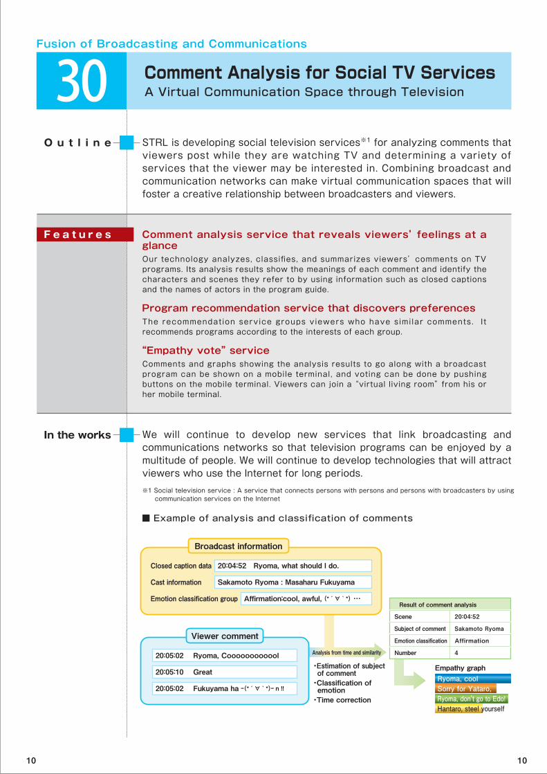
Comment analysis service that reveals viewers’ feelings at a glanceOur technology analyzes, classifies, and summarizes viewers’ comments on TV programs. Its analysis results show the meanings of each comment and identify the characters and scenes they refer to by using information such as closed captions and the names of actors in the program guide.
Program recommendation service that discovers preferencesThe recommendation service groups viewers who have simi lar comments. I t recommends programs according to the interests of each group.
“Empathy vote” service Comments and graphs showing the analysis results to go along with a broadcast program can be shown on a mobile terminal, and voting can be done by pushing buttons on the mobile terminal. Viewers can join a “virtual living room” from his or her mobile terminal.
F e a t u r e s
■ Example of analysis and classification of comments
Fusion of Broadcasting and Communications
Broadcast information
20:04:52 Ryoma, what should I do.Closed caption data
Sakamoto Ryoma : Masaharu FukuyamaCast information
Affirmation:cool, awful, (*´∀`*) …Emotion classification groupResult of comment analysis
Empathy graph・Estimation of subject of comment ・Classification of emotion・Time correction
Scene
Subject of comment
Emotion classification
Number
20:04:52
Sakamoto Ryoma
Affirmation
4
Ryoma, coolSorry for Yataro, Ryoma, don't go to Edo!Hantaro, steel yourself
Analysis from time and similarity
Viewer comment
20:05:02 Ryoma, Coooooooooool
20:05:10 Great
20:05:02 Fukuyama ha ‐‐(*´∀`*)‐‐ n !!
※1 Social television service : A service that connects persons with persons and persons with broadcasters by using communication services on the Internet
10 10
31 Relevant Retrieval System for NHK Creative LibraryTechnology that Retrieves Videos by Referring to a Variety of Relevant Factors
This exhibit shows Relevant Retrieval System that searches for video stored in the online NHK Creative Library※1. The system looks for similar content and similar images, and its results are presented in an easy- to-understand manner.
O u t l i n e
We are carrying out public experiments on the NHK homepage. We are also researching ways to make useful metadata for searching more efficiently and search methods based on variety of relevant factors.
In the works
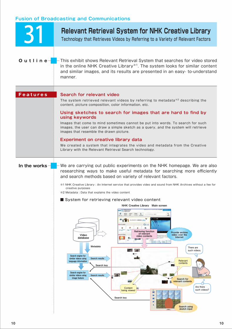
Search for relevant video The system retrieved relevant videos by referring to metadata※2 describing the content, picture composition, color information, etc.
Using sketches to search for images that are hard to find by using keywordsImages that come to mind sometimes cannot be put into words. To search for such images, the user can draw a simple sketch as a query, and the system will retrieve images that resemble the drawn picture.
Experiment on creative library data We created a system that integrates the video and metadata from the Creative Library with the Relevant Retrieval Search technology.
F e a t u r e s
■ System for retrieving relevant video content
Fusion of Broadcasting and Communications
※1 NHK Creative Library : An Internet service that provides video and sound from NHK Archives without a fee for creative purposes ※2 Metadata : Data that explains the video content
Videodatabase
Metadata
Search key
Search key
Search engine for similar videos using language information
Retrieving functionof relevant
video contents
Search engine for similar videos using
image feature
Search results
Search results
Provide archive video over the
Internet
Search forrelevant contents
Search usingsketch input
Contentbeing viewed
There are such videos.
Are theresuch videos?
NHK Creative Library Main screen
Relevantcontents
10 10
32 CG Content Production Services using Cloud ComputingProgram Production Anywhere, Anytime via the Internet
STRL is doing research on CG content production services for end users using cloud computing※1. The Web services that this system supports range from materials searches and CG content production using TVML※2 to live video streaming on the server side. End users can quickly and easily access these functions through their PCs and mobile devices.
O u t l i n e
Our goal is to make cloud-based CG content production services a practical reality.
In the works
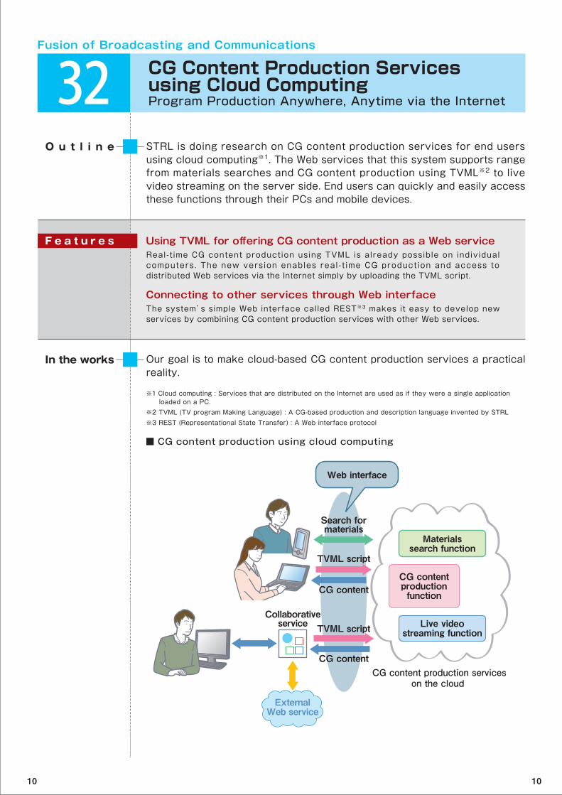
Using TVML for offering CG content production as a Web service Real-time CG content production using TVML is already possible on individual computers. The new version enables real-t ime CG production and access to distributed Web services via the Internet simply by uploading the TVML script.
Connecting to other services through Web interfaceThe system’s simple Web interface called REST※3 makes it easy to develop new services by combining CG content production services with other Web services.
F e a t u r e s
■ CG content production using cloud computing
Fusion of Broadcasting and Communications
※1 Cloud computing : Services that are distributed on the Internet are used as if they were a single application loaded on a PC.※2 TVML (TV program Making Language) : A CG-based production and description language invented by STRL※3 REST (Representational State Transfer) : A Web interface protocol
ExternalWeb service
CG content
TVML script
CG content
Collaborativeservice TVML script
Search formaterials
Materialssearch function
CG content production serviceson the cloud
CG contentproductionfunction
Live videostreaming function
Web interface
10 10
33 Flexible Program Production SystemFast Web Editing System based on Distributed Processing for Broadcasting Stations
The Flexible Program Production System is a Web-based video editing system with customizable interfaces. The system is based on a configurable distributed processing system. It has a large distributed video file system that is not limited in its amount of storage and technology for making stable high-speed file transfer over long-distance IP networks.
O u t l i n e
We plan to release our system as open source technology and hope to make it the editing system of the cloud-computing era.
In the works
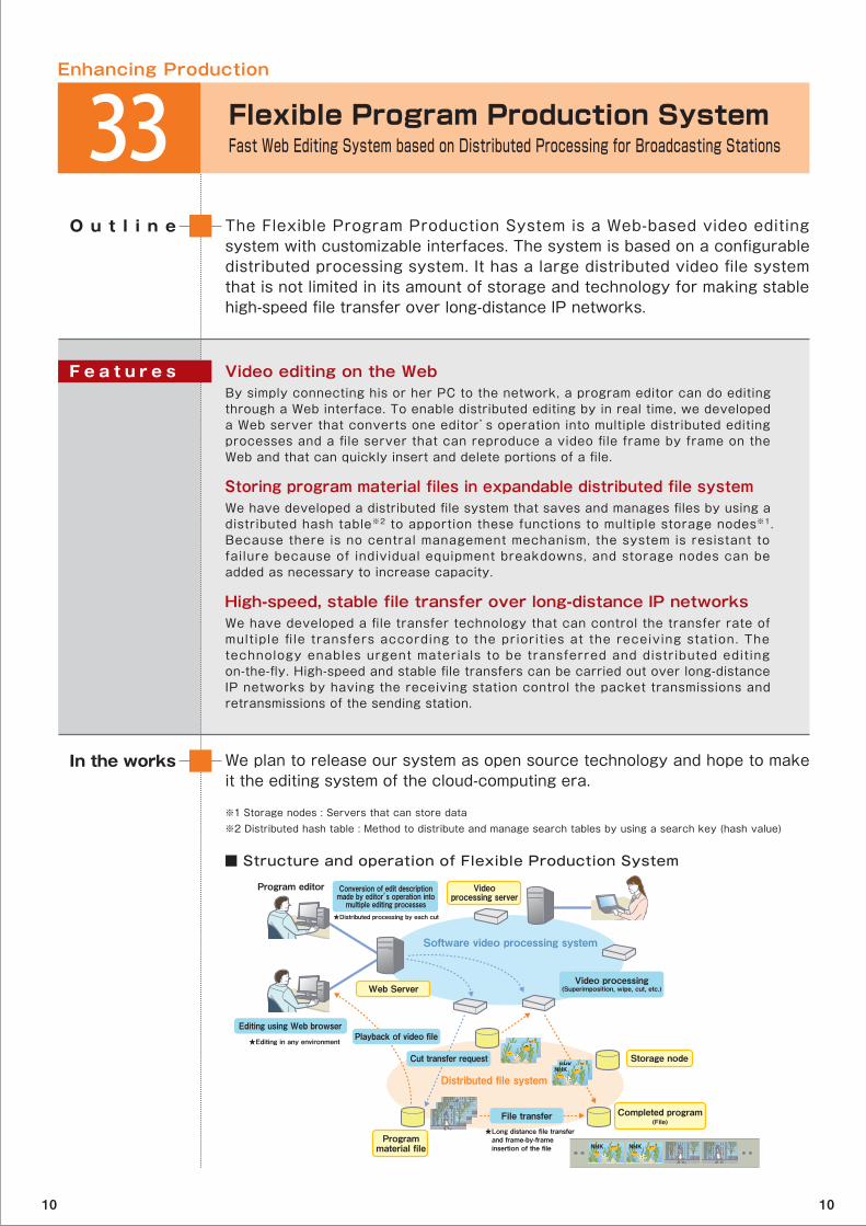
Video editing on the WebBy simply connecting his or her PC to the network, a program editor can do editing through a Web interface. To enable distributed editing by in real time, we developed a Web server that converts one editor’s operation into multiple distributed editing processes and a file server that can reproduce a video file frame by frame on the Web and that can quickly insert and delete portions of a file.
Storing program material files in expandable distributed file systemWe have developed a distributed file system that saves and manages files by using a distributed hash table※2 to apportion these functions to multiple storage nodes※1. Because there is no central management mechanism, the system is resistant to failure because of individual equipment breakdowns, and storage nodes can be added as necessary to increase capacity.
High-speed, stable file transfer over long-distance IP networksWe have developed a file transfer technology that can control the transfer rate of multiple file transfers according to the priorit ies at the receiving station. The technology enables urgent materials to be transferred and distributed editing on-the-fly. High-speed and stable file transfers can be carried out over long-distance IP networks by having the receiving station control the packet transmissions and retransmissions of the sending station.
F e a t u r e s
■ Structure and operation of Flexible Production System
Enhancing Production
※1 Storage nodes : Servers that can store data ※2 Distributed hash table : Method to distribute and manage search tables by using a search key (hash value)
Conversion of edit descriptionmade by editor’s operation into
multiple editing processes
Program editor
Software video processing system
Distributed file system
Videoprocessing server
Web Server
Storage node
Programmaterial file
Completed program(File)
Editing using Web browser
Video processing(Superimposition, wipe, cut, etc.)
★Distributed processing by each cut
★Long distance file transfer and frame-by-frame insertion of the file
★Editing in any environment Playback of video file
Cut transfer request
File transfer
NHK
NHK NHK
NHK
10 10
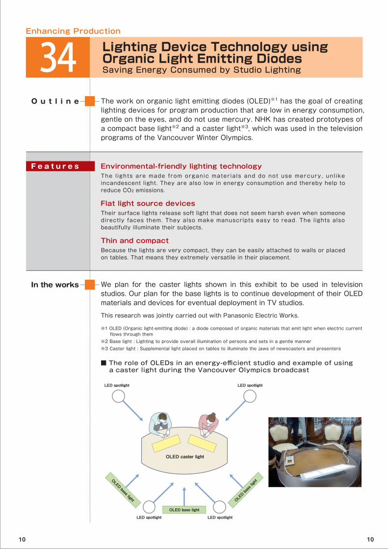
The work on organic light emitting diodes (OLED)※1 has the goal of creating lighting devices for program production that are low in energy consumption, gentle on the eyes, and do not use mercury. NHK has created prototypes of a compact base light※2 and a caster light※3, which was used in the television programs of the Vancouver Winter Olympics.
O u t l i n e
We plan for the caster lights shown in this exhibit to be used in television studios. Our plan for the base lights is to continue development of their OLED materials and devices for eventual deployment in TV studios.
This research was jointly carried out with Panasonic Electric Works.
In the works
Environmental-friendly lighting technologyThe l ights are made from organic mater ia ls and do not use mercury, unl ike incandescent light. They are also low in energy consumption and thereby help to reduce CO2 emissions.
Flat light source devices Their surface lights release soft light that does not seem harsh even when someone directly faces them. They also make manuscripts easy to read. The lights also beautifully illuminate their subjects.
Thin and compactBecause the lights are very compact, they can be easily attached to walls or placed on tables. That means they extremely versatile in their placement.
F e a t u r e s
■ The role of OLEDs in an energy-efficient studio and example of using a caster light during the Vancouver Olympics broadcast
※1 OLED (Organic light-emitting diode) : a diode composed of organic materials that emit light when electric current flows through them※2 Base light : Lighting to provide overall illumination of persons and sets in a gentle manner※3 Caster light : Supplemental light placed on tables to illuminate the jaws of newscasters and presenters
Enhancing Production
34 Lighting Device Technology using Organic Light Emitting DiodesSaving Energy Consumed by Studio Lighting
OLED caster light
OLED base light
OLED base lightOLED base light
LED spotlight LED spotlight
LED spotlightLED spotlight
10 10
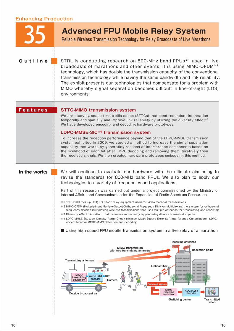
STRL is conducting research on 800-MHz band FPUs※1 used in live broadcasts of marathons and other events. It is using MIMO-OFDM※2 technology, which has double the transmission capacity of the conventional transmission technology while having the same bandwidth and link reliability. The exhibit presents our technologies that compensate for a problem with MIMO whereby signal separation becomes difficult in line-of-sight (LOS) environments.
O u t l i n e
We will continue to evaluate our hardware with the ultimate aim being to revise the standards for 800-MHz band FPUs. We also plan to apply our technologies to a variety of frequencies and applications.
Part of this research was carried out under a project commissioned by the Ministry of Internal Affairs and Communication for the Expansion of Radio Spectrum Resources
In the works
STTC-MIMO transmission systemWe are studying space-time trellis codes (STTCs) that send redundant information temporally and spatially and improve link reliability by utilizing the diversity effect※3. We have developed encoding and decoding hardware prototypes.
LDPC-MMSE-SIC※4 transmission systemTo increase the reception performance beyond that of the LDPC-MMSE transmission system exhibited in 2009, we studied a method to increase the signal separation capability that works by generating replicas of interference components based on the likelihood of each bit after LDPC decoding and removing them iteratively from the received signals. We then created hardware prototypes embodying this method.
F e a t u r e s
■ Using high-speed FPU mobile transmission system in a live relay of a marathon
※1 FPU (Field Pick-up Unit) : Outdoor relay equipment used for video material transmissions※2 MIMO-OFDM (Multiple-Input Multiple-Output-Orthogonal Frequency Division Multiplexing) : A system for orthogonal frequency division multiplexing wireless transmissions that uses multiple antennas for transmitting and receiving※3 Diversity effect : An effect that increases redundancy by preparing diverse transmission paths※4 LDPC-MMSE-SIC (Low-Density Parity-Check-Minimum Mean Square Error-Soft Interference Cancellation) : LDPC coded iterative MMSE-MIMO detection and decoding
Enhancing Production
35 Advanced FPU Mobile Relay SystemReliable Wireless Transmission Technology for Relay Broadcasts of Live Marathons
Received signals
MIMO transmissionwith two transmitting antennas
Outside broadcast van
Transmitting antennas
Camera
Reception point
MIMOreceivingequipment
AVC/H.264decoder
Receiving antennas
Optical fiber
Switching center Transmittedvideo
MIMOtransmittingequipment
AVC/H.264encoder
10 10
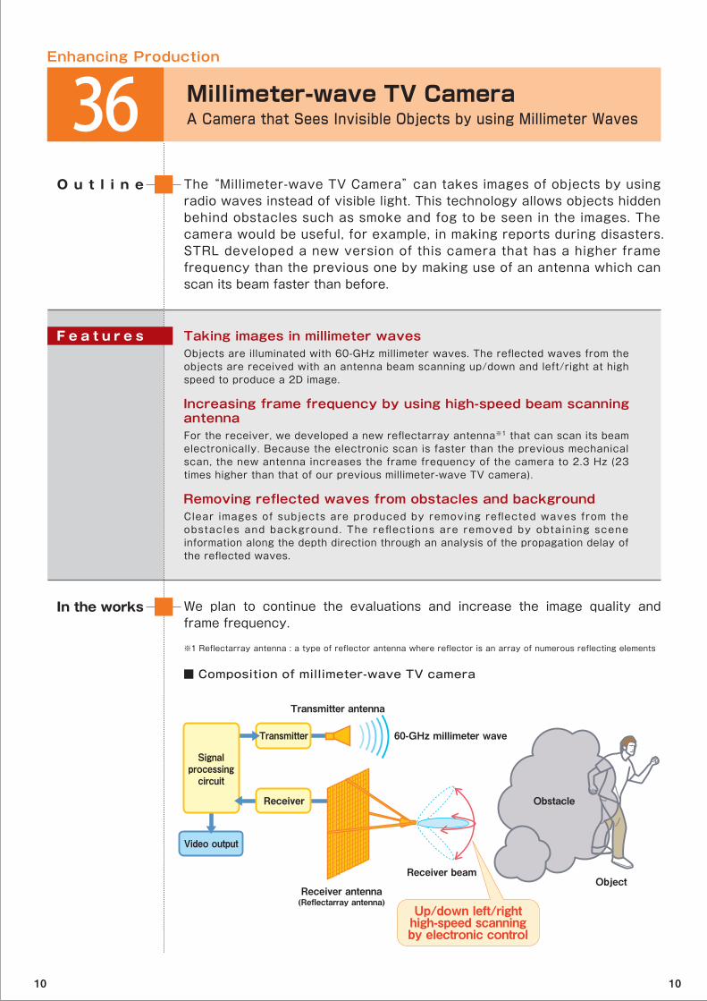
The “Millimeter-wave TV Camera” can takes images of objects by using radio waves instead of visible light. This technology allows objects hidden behind obstacles such as smoke and fog to be seen in the images. The camera would be useful, for example, in making reports during disasters. STRL developed a new version of this camera that has a higher frame frequency than the previous one by making use of an antenna which can scan its beam faster than before.
O u t l i n e
We plan to continue the evaluations and increase the image quality and frame frequency.
In the works
Taking images in millimeter wavesObjects are illuminated with 60-GHz millimeter waves. The reflected waves from the objects are received with an antenna beam scanning up/down and left/right at high speed to produce a 2D image.
Increasing frame frequency by using high-speed beam scanning antennaFor the receiver, we developed a new reflectarray antenna※1 that can scan its beam electronically. Because the electronic scan is faster than the previous mechanical scan, the new antenna increases the frame frequency of the camera to 2.3 Hz (23 times higher than that of our previous millimeter-wave TV camera).
Removing reflected waves from obstacles and backgroundClear images of subjects are produced by removing reflected waves from the obstacles and background. The reflect ions are removed by obtaining scene information along the depth direction through an analysis of the propagation delay of the reflected waves.
F e a t u r e s
■ Composition of millimeter-wave TV camera
※1 Reflectarray antenna : a type of reflector antenna where reflector is an array of numerous reflecting elements
Enhancing Production
36 Millimeter-wave TV CameraA Camera that Sees Invisible Objects by using Millimeter Waves
Video output
Transmitter 60-GHz millimeter wave
Transmitter antenna
ObjectReceiver beam
Receiver antenna(Reflectarray antenna)
Obstacle
Signalprocessingcircuit
Receiver
Up/down left/righthigh-speed scanningby electronic control
10 10
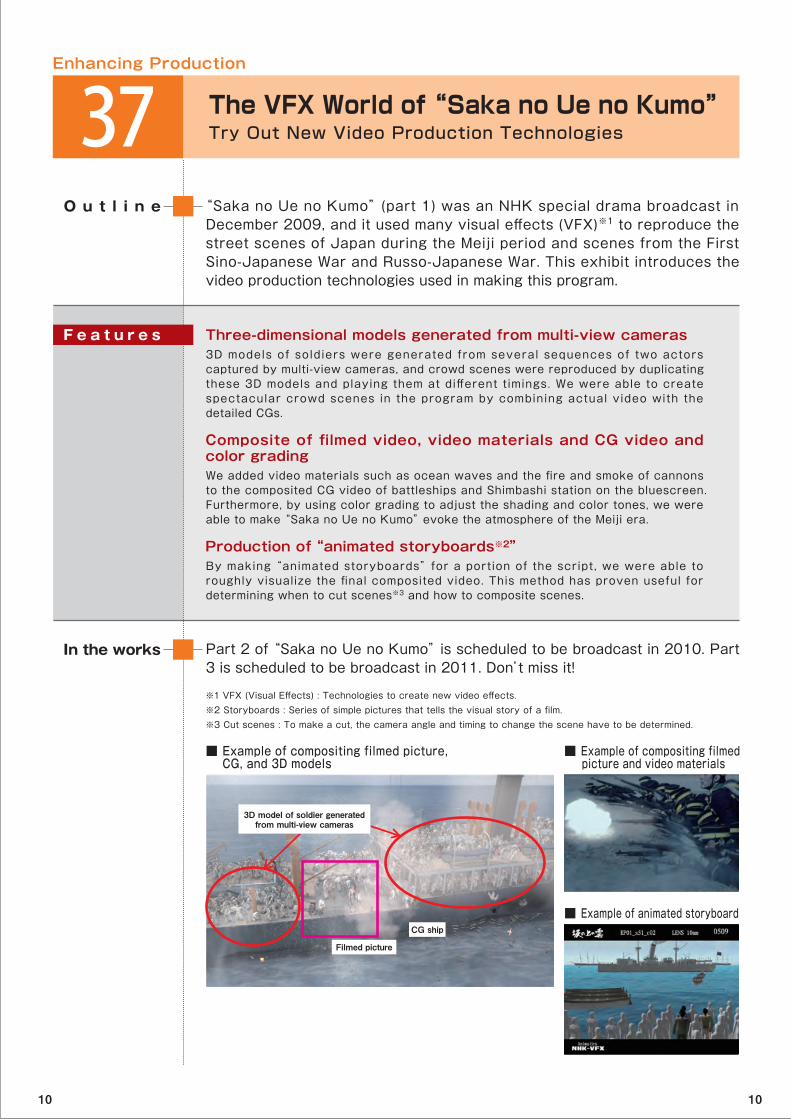
“Saka no Ue no Kumo” (part 1) was an NHK special drama broadcast in December 2009, and it used many visual effects (VFX)※1 to reproduce the street scenes of Japan during the Meiji period and scenes from the First Sino-Japanese War and Russo-Japanese War. This exhibit introduces the video production technologies used in making this program.
O u t l i n e
Part 2 of “Saka no Ue no Kumo” is scheduled to be broadcast in 2010. Part 3 is scheduled to be broadcast in 2011. Don’t miss it!
In the works
Three-dimensional models generated from multi-view cameras3D models of soldiers were generated from several sequences of two actors captured by multi-view cameras, and crowd scenes were reproduced by duplicating these 3D models and playing them at different timings. We were able to create spectacular crowd scenes in the program by combining actual video with the detailed CGs.
Composite of filmed video, video materials and CG video and color gradingWe added video materials such as ocean waves and the fire and smoke of cannons to the composited CG video of battleships and Shimbashi station on the bluescreen. Furthermore, by using color grading to adjust the shading and color tones, we were able to make “Saka no Ue no Kumo” evoke the atmosphere of the Meiji era.
Production of “animated storyboards※2”By making “animated storyboards” for a portion of the script, we were able to roughly visualize the final composited video. This method has proven useful for determining when to cut scenes※3 and how to composite scenes.
F e a t u r e s
■ Example of compositing filmed picture, CG, and 3D models
■ Example of compositing filmed picture and video materials
■ Example of animated storyboard
※1 VFX (Visual Effects) : Technologies to create new video effects.※2 Storyboards : Series of simple pictures that tells the visual story of a film.※3 Cut scenes : To make a cut, the camera angle and timing to change the scene have to be determined.
Enhancing Production
37 The VFX World of “Saka no Ue no Kumo”Try Out New Video Production Technologies
Filmed picture
CG ship
3D model of soldier generatedfrom multi-view cameras
10 10
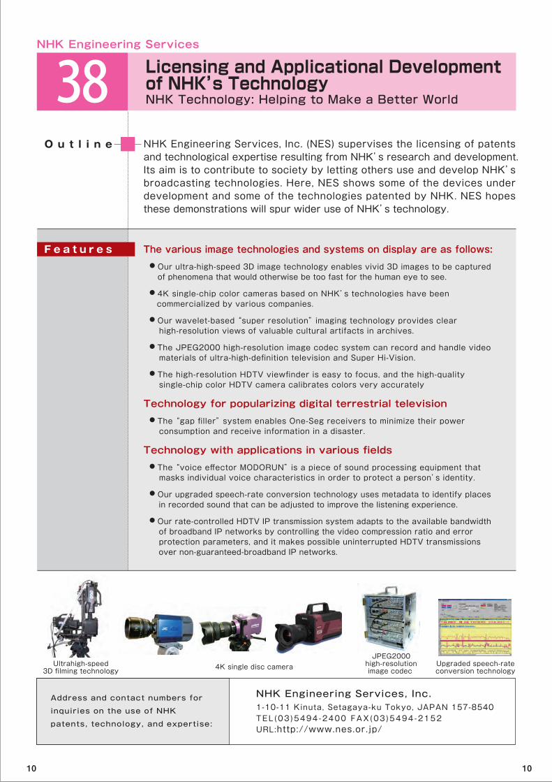
NHK Engineering Services, Inc. (NES) supervises the licensing of patents and technological expertise resulting from NHK’s research and development. Its aim is to contribute to society by letting others use and develop NHK’s broadcasting technologies. Here, NES shows some of the devices under development and some of the technologies patented by NHK. NES hopes these demonstrations will spur wider use of NHK’s technology.
O u t l i n e
The various image technologies and systems on display are as follows: ● Our ultra-high-speed 3D image technology enables vivid 3D images to be captured of phenomena that would otherwise be too fast for the human eye to see.
● 4K single-chip color cameras based on NHK’s technologies have been commercialized by various companies.
● Our wavelet-based “super resolution” imaging technology provides clear high-resolution views of valuable cultural artifacts in archives.
● The JPEG2000 high-resolution image codec system can record and handle video materials of ultra-high-definition television and Super Hi-Vision.
● The high-resolution HDTV viewfinder is easy to focus, and the high-quality single-chip color HDTV camera calibrates colors very accurately Technology for popularizing digital terrestrial television ● The “gap filler” system enables One-Seg receivers to minimize their power consumption and receive information in a disaster.
Technology with applications in various fields ● The “voice effector MODORUN” is a piece of sound processing equipment that masks individual voice characteristics in order to protect a person’s identity.
● Our upgraded speech-rate conversion technology uses metadata to identify places in recorded sound that can be adjusted to improve the listening experience.
● Our rate-controlled HDTV IP transmission system adapts to the available bandwidth of broadband IP networks by controlling the video compression ratio and error protection parameters, and it makes possible uninterrupted HDTV transmissions over non-guaranteed-broadband IP networks.
F e a t u r e s
NHK Engineering Services
Ultrahigh-speed3D filming technology 4K single disc camera
NHK Engineering Services, Inc.1-10-11 Kinuta, Setagaya-ku Tokyo, JAPAN 157-8540TEL (03 )5494-2400 FAX(03 )5494-2152 URL:http://www.nes.or.jp/
Address and contact numbers for
inquiries on the use of NHK
patents, technology, and expertise:
JPEG2000high-resolutionimage codec
Upgraded speech-rateconversion technology
38 Licensing and Applicational Development of NHK’s TechnologyNHK Technology: Helping to Make a Better World
10 10
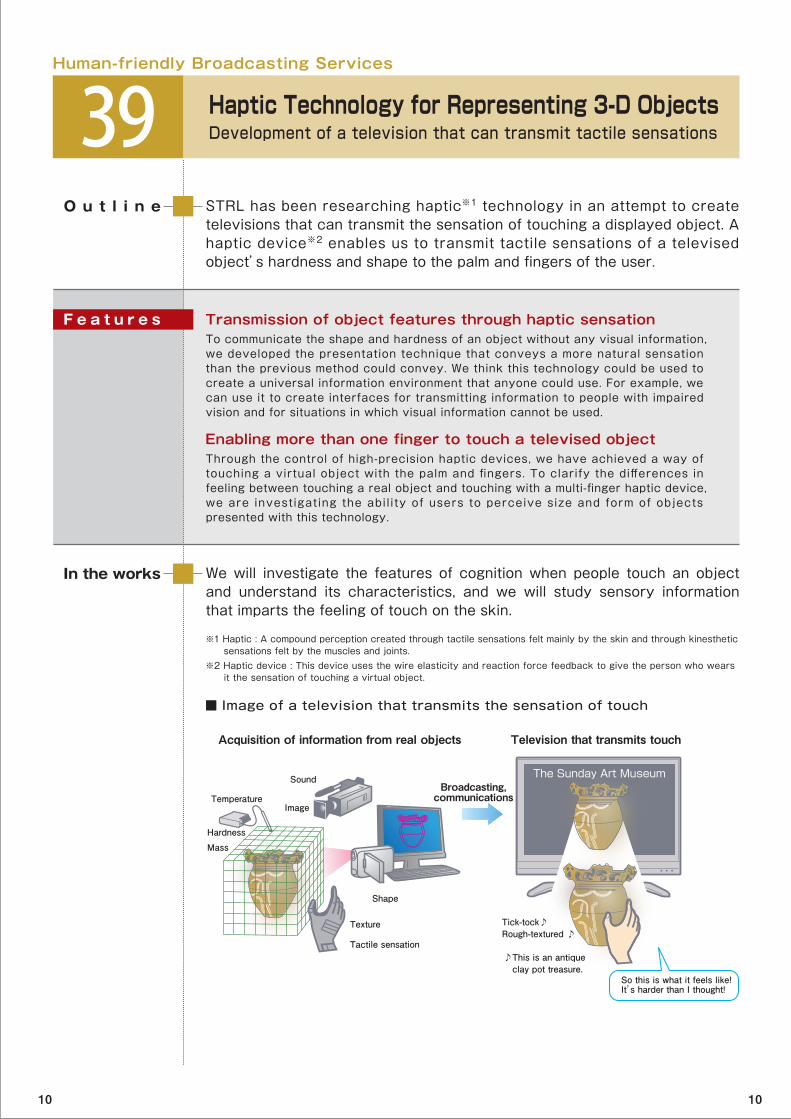
STRL has been researching haptic※1 technology in an attempt to create televisions that can transmit the sensation of touching a displayed object. A haptic device※2 enables us to transmit tactile sensations of a televised object’s hardness and shape to the palm and fingers of the user.
O u t l i n e
We will investigate the features of cognition when people touch an object and understand its characteristics, and we will study sensory information that imparts the feeling of touch on the skin.
In the works
Transmission of object features through haptic sensation To communicate the shape and hardness of an object without any visual information, we developed the presentation technique that conveys a more natural sensation than the previous method could convey. We think this technology could be used to create a universal information environment that anyone could use. For example, we can use it to create interfaces for transmitting information to people with impaired vision and for situations in which visual information cannot be used.
Enabling more than one finger to touch a televised objectThrough the control of high-precision haptic devices, we have achieved a way of touching a virtual object with the palm and fingers. To clarify the differences in feeling between touching a real object and touching with a multi-finger haptic device, we are investigating the abil i ty of users to perceive size and form of objects presented with this technology.
F e a t u r e s
■ Image of a television that transmits the sensation of touch
※1 Haptic : A compound perception created through tactile sensations felt mainly by the skin and through kinesthetic sensations felt by the muscles and joints. ※2 Haptic device : This device uses the wire elasticity and reaction force feedback to give the person who wears it the sensation of touching a virtual object.
Human-friendly Broadcasting Services
39 Haptic Technology for Representing 3-D ObjectsDevelopment of a television that can transmit tactile sensations
Acquisition of information from real objects
Broadcasting, communications
Television that transmits touch
So this is what it feels like!It’s harder than I thought!
Tick-tock♪Rough-textured ♪
♪This is an antique clay pot treasure.
Shape
Texture
Tactile sensation
Mass
Hardness
Temperature
Sound
Image
The Sunday Art Museum
10 10

STRL is developing a small color camera with a single-chip color image sensor that uses stacked organic films. STRL fabricated a high-definition sensor by increasing the number of pixels and reducing the pixel size.
O u t l i n e
We will increase the concentration of transparent TFT circuits to make an organic image sensor with even higher resolution.
Developing transparent TFT circuits is jointly carried out with Kochi University of Technology.
Part of developing organic films is jointly carried out with Saitama University.
In the works
Structure of organic image sensorThe organic image sensor is a single-chip color image sensor with three layers of organic film, each sensitive to only one of the three primary color components of light. The layers are stacked with three transparent TFT※1 circuits that read out signals from each film.
Organic film selects a color and creates an electric signalEach organic film absorbs light of only one of the three primary color components and converts it into an electric signal. The light of the other colors passes through to the layers below. The resulting single chip color image sensor has the same characteristics as a three-chip color image sensor that uses a prism.
High concentration of transparent TFTsWe made progress in miniaturizing transparent TFT circuits and reduced the pixel pitch to 100μm, or one-sixth of the size the predecessor. In addition, we increased the number of pixels by more than eight times, to 12,200 pixels (128 horizontal x 96 vertical).
F e a t u r e s
■ Color camera imaging system
※1 TFT : Thin Film Transistor
Next Generation Broadcasting Devices
40 Organic Image Sensor Development of compact, high-quality camera
Imaging system used in current TV cameras(3 chip system)
Image sensor
Light separation prism
Light
Single chip imaging systemusing an organic image sensor
Transparent TFT circuit used for signal reading
Organic image sensor
Red light
Green light
Green
Blue light
Red
Blue
Organic film used for blue lightOrganic film used for green light
Organic film used for red light
10 10

To improve the quality of science television programs and the performance of X-ray diagnostic equipment, STRL has developed an ultra-high-sensitivity camera tube that has a fiber optic plate (FOP※1) as a substrate. The FOP can optically connect a HARP※2 photoconductive film to an X-ray fluorescent screen or to an image intensifier※3 sensitive to near-infrared light.
O u t l i n e
We will reduce the occurrence and severity of defects and develop an FOP substrate for field emitter array image sensors, which are compact HARP imaging devices.
We are working together with the University of Tsukuba and the High Energy Accelerator Research Organization on the X-ray diagnosis equipment.
In the works
Avalanche multiplication in HARP photoconductive film on FOP substrate The substrate of a HARP photoconductive film must be very flat. We developed a new polishing technology that flattens the FOP surface that consists of three kinds of glass with differing hardnesses. This new technology makes it possible for a HARP photoconductive film on an FOP substrate to achieve avalanche multiplication.
Ultrahigh-sensitivity near-infrared light images Ordinary HARP camera tubes have had no sensitivity to near-infrared light. However, an FOP-HARP tube can be directly connected to an image intensifier that has such sensitivity, thereby making it possible for a HARP camera to shoot high-quality, high-sensitivity, near-infrared images.
High-quality X-ray images requiring a lower dose of radiation By directly connecting FOP-HARP camera tube to an X-ray fluorescent screen, we can greatly reduce the concentration of contrast material and the radiation dose that X-ray diagnostics give to the patient. Moreover, the HARP camera makes it possible to observe small blood vessels in more detail than would be possible otherwise.
F e a t u r e s
■ Structure of FOP-HARP camera tube
※1 Fiber Optic Plate (FOP) : An FOP is an optical device that bundles millions of micron-sized optic fibers together. ※2 HARP (High-gain Avalanche Rushing amorphous Photoconductor) : HARP is an ultra-high sensitivity photoconductive film that exploits the phenomenon of avalanche multiplication. ※3 Image intensifier : A device that uses high voltage to accelerate electrons generated from incident light and intensifies light by causing them to collide on a phosphor screen.
Next Generation Broadcasting Devices
41 HARP Imaging Device using Fiber Optic Plate High-quality images made from near-infrared light and X-rays
FOP substrate
Direct connection possibleSurfaceenlargement
FOP-HARP camera tube 5μm
HARP photoconductive film
Image intensifier(from near-infrared light to visible light)
Fluorescent screen(from X-rays to visible light)
10 10

STRL has been working on a flexible television display that is thin, lightweight, bendable, and easy to carry. STRL used a coating method to fabricate an organic light emitting diode※1 panel driven by organic TFTs※2 and used it to make a high-resolution flexible display.
O u t l i n e
We will continue with our development of printing and coating methods and new materials in order to create a large flexible displays.
In the works
High-resolution display panelWe fabricated a 5-inch diagonal flexible light emitting diode display with organic TFTs formed on a plastic substrate. The display is QVGA, and it has 320×240 pixels, which is four times that of the display in the Open House 2009.
Coating method for organic TFTsThe coating method for forming a gate insulating layer of organic TFTs is suitable for fabricating large screens. It is a simple method that improves the uniformity and reliability of organic TFTs.
Organic light emitting diode materialsFor patterning high-definit ion pixels sensit ive to the three primary colors, we developed high-emission-efficiency light emitting diode materials that can be vacuum deposited or ink-jet printed.
F e a t u r e s
■ Cross-sectional diagram of a flexible display (1 pixel element)
※1 Organic light emitting diode : A device made from organic compounds that emit light when an electric current flows through them.※2 TFT : Thin Film Transistor
Next Generation Broadcasting Devices
42 Flexible Organic Light Emitting Diode DisplayDevelopment of a flexible television display
Phosphorescent organic lightemitting diode
Organicsemiconductor
Coated gateinsulating film
(Polymer material)Plasticsubstrate
Lightemission
Organic TFT
10 10
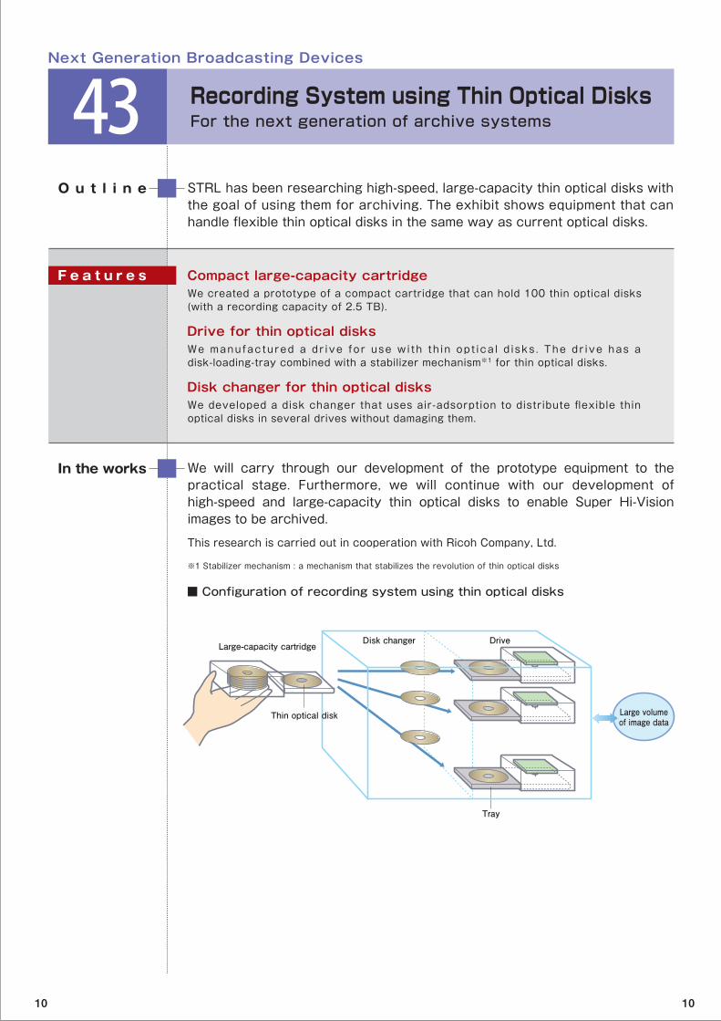
STRL has been researching high-speed, large-capacity thin optical disks with the goal of using them for archiving. The exhibit shows equipment that can handle flexible thin optical disks in the same way as current optical disks.
O u t l i n e
We will carry through our development of the prototype equipment to the practical stage. Furthermore, we will continue with our development of high-speed and large-capacity thin optical disks to enable Super Hi-Vision images to be archived.
This research is carried out in cooperation with Ricoh Company, Ltd.
In the works
Compact large-capacity cartridgeWe created a prototype of a compact cartridge that can hold 100 thin optical disks (with a recording capacity of 2.5 TB).
Drive for thin optical disksWe manufactured a dr ive for use w i th th in opt ica l d isks . The dr ive has a disk-loading-tray combined with a stabilizer mechanism※1 for thin optical disks.
Disk changer for thin optical disksWe developed a disk changer that uses air-adsorption to distribute flexible thin optical disks in several drives without damaging them.
F e a t u r e s
■ Configuration of recording system using thin optical disks
※1 Stabilizer mechanism : a mechanism that stabilizes the revolution of thin optical disks
Next Generation Broadcasting Devices
43 Recording System using Thin Optical DisksFor the next generation of archive systems
Large volumeof image data
Disk changer Drive
Tray
Large-capacity cartridge
Thin optical disk
10 10

STRL has been studying holographic recording technology that can store huge amounts of data and record Super Hi-Vision video signals. STRL has enlarged numerical aperture※1of the object lens for recording and reproduction and has built experimental equipment that has four times the recording density of the equipment shown at the Open House 2009.
O u t l i n e
We will continue to develop our holographic recording technology’s signal processing methods and optimize its optical systems. Our eventual goal is to make holographic recording equipment that can record Super Hi-Vision video signals.
In the works
Angle multiplexing※2 recording with beam scanningWe increased the access speed by changing from a method that rotates the recording medium to one that controls the incident angle of the beam on the recording medium. We also made it possible to record and reproduce in any type of recording medium configuration.
Compensating for distortionVibrations, temperature changes, and changes in recording medium volume cause d i s to r t i ons i n the record ing . To ma in ta in h igh s i gna l qua l i t y under such circumstances, we use wavefront control techniques to achieve the opt imal conditions for beam wavefronts in recording and reproduction.
F e a t u r e s
■ Principles of angle multiplexing holographic recording and reproduction using beam scanning
※1 Numerical aperture : value indicating the extent to which a beam can be converged. A larger numerical aperture means the beam can be made to converge on a smaller area.※2 Angle multiplexing : A holographic recording method that changes the relative angles between incident beam and the recording medium and makes it possible to record different data in the same place.
Next Generation Broadcasting Devices
44 High-density Holographic Recording Technology Development of ultra-large-capacity, high-data-transfer-rate recording systems
Angle 1
Angle 1
Angle n
Angle n
・・・
・・・Reproduced data
Recorded dataHolographic
recording medium
Reference beam (while recording) multiplexing recording by controlling the incident beam angle
Reference beam(while reproducing) reproducing by controlling the incident beam angle
10 10
Poster Exhibit
Delay Stabilization Method for Wireless Local Area NetworksDevelopment of a jitter-free network
STRL has developed jitter-free technologies to suppress variations in packet transmission delay. These technologies can be used for timing events and synchronizing signals in wired and wireless LANs. The exhibit demons t ra tes a t echno logy fo r w i re less LANs tha t s tab i l i zes the transmission delay by compensating for random delay variations caused by the LAN’s collision avoidance mechanism.
High-performance Video Coding TechnologyUltra-high-level compression for Super Hi-Vision
This exhibit presents new video coding technologies for Super Hi-Vision broadcasting. It compares video decoded with the latest method with video decoded with conventional methods. New coding methods outperform conventional video coding standards such as AVC/H.264.
Estimating TV Viewers’ Psychological State by using Multimodal Brain Function Imaging Measuring※11 neurological function by using fNIRS※22and EEG※3
To produce better content for television programs, STRL has been to investigating how viewers perceive and react to content. STRL simultaneously uses the neuroscientific methods of functional near-infrared spectroscopy and electroencephalography to measure blood flow related to neural activity in the brain and brain waves. ※1 Multi-modal measurement : Use of several methods simultaneously to measure different aspects of brain function※2 fNIRS (functional Near-Infrared Spectroscopy) : A non-invasive method of measuring brain blood flow related to neural activity※3 EEG (electroencephalography) : A method of measuring electrical activity in the brain
High-Quality Speech Synthesis Method for Definite Form Sentences Applications for weather reports
I t is necessary to build a speech database for voice synthesizers to produce speech. STRL developed a technology that synthesizes high-quality speech wi thout expanding the s ize of the database when the input sentences are written in Japanese definite form.
10 10
Poster Exhibit
HARP Photoconductive Film with High Quantum EfficiencyFor image sensors with extremely high sensitivity
The goal is to create an ultra-sensitive camera that shoots high-quality images. To this end, STRL has been improving the photoelectric-conversion efficiency※1 of high-gain avalanche rushing amorphous photoconductor (HARP) film. The latest HARP film has a photosensitive layer made from new materials and an amorphous selenium avalanche multiplication layer. It is capable o f prov id ing s tab le avalanche mul t ip l icat ion wi th quantum efficiencies of more than 80% in the visible light region.
This research is jointly carried out with Hamamatsu Photonics K.K.
※1 Photoelectric-conversion efficiency : The number of generated charge per an incident photon
Electret Charging Method for Vibration-driven Power GeneratorA compact emergency power supply that is environmentally friendly
STRL has been researching energy harvest ing technology that uses mechanical vibrations, heat, and light in the environment to produce electric power that can be used in emergencies. To increase the output of devices tha t genera te power f rom v ibra t ions , STRL deve loped an e lec t re t fabrication process that involves irradiation of soft X-rays※1. The resulting electret can accumulate more charge※2.※1 soft X-rays : X-rays with low permeability※2 electret : a resin that stores charges
Magneto-optical Observation of Magnetic Domain Structures Progress on a high-speed magnetic recording device with no moving parts
To develop a high-speed recording device with no moving parts, STRL is look ing to exp lo i t u l t ra fas t m igra t ion phenomena in the magne t ic micro-domains※1 of magnetic nanowires※2. By using magneto-optical imaging, STRL observed trapped magnetic domains in a magnetic nanowire in real-time. ※1 magnetic micro-domain : the smallest unit/region of a magnetic material that has magnetic properties※2 magnetic nanowire : thin wire-like nanostructure fabricated from ferromagnetic materials, approximately 1/100th to 1/1000th the width of a human hair
10 10
Poster Exhibit
Improvement of Electrode Properties for Reducing Power Consumption of Plasma Displays For energy saving plasma displays
STRL has been researching electrode materials that have a low operating voltage in order to reduce the power consumption of plasma display panels (PDPs). I t improved the fabricat ion process of these electrodes and succeeded in reducing the discharge delay time, which had been a problem with these electrode materials.
Vertical Organic Transistor with Low Voltage and High Current OperationDevelopment of a drive for a large screen, high definition flexible display
STRL has been researching high-performance organic transistors for the large-screen, high-definition flexible displays of the future. It developed a transistor with a large current and low operating voltage. The transistor has a vertical channel structure※1, and the molecular orientation※2 of the organic semiconductors is controlled.※1 Vertical channel structure : Structuring the charge transport within transistors in the vertical direction to the substrate※2 Molecular orientation : the arrangement of the molecules
Light Modulation Device Driven by Spin Transfer Switching Progress on ultra-high-definition displays for 3D television
STRL has been developing a submicron spatial light modulation device※1 (STS-SLM) driven by spin transfer switching※2. The device has potential uses in fu ture u l t ra -h igh-defini t ion d isp lays dev ices that w i l l show holographic 3D TV. The exhibit shows the structure of a device for lowering the drive current and materials that can improve the light modulation properties.
This research is jointly carried out with Nagaoka University of Technology.
Part of this research is carried out under a project commissioned by the National Institute of Information and Communications Technology.
※1 Spatial light modulation device : A device that controls the contrast of reflected light. Devices developed by STRL control the contrast of lightness and darkness by changing the magnetic direction of the pixels in the display. ※2 Spin transfer switching : A technology to control the magnetic direction (S and N poles) of magnetic materials by using electrons with ordered spins
10 10
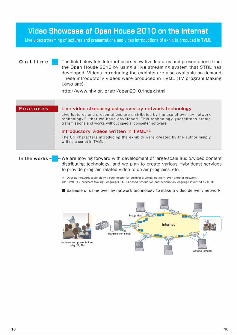
Video Showcase of Open House 2010 on the InternetLive video streaming of lectures and presentations and video introductions of exhibits produced in TVML
The link below lets Internet users view live lectures and presentations from the Open House 2010 by using a live streaming system that STRL has developed. Videos introducing the exhibits are also available on-demand. These introductory videos were produced in TVML (TV program Making Language).
http://www.nhk.or.jp/strl/open2010/index.html
O u t l i n e
We are moving forward with development of large-scale audio/video content distributing technology, and we plan to create various Hybridcast services to provide program-related video to on-air programs, etc.
In the works
Live video streaming using overlay network technologyLive lectures and presentations are distributed by the use of overlay network technology※1 that we have deve loped . Th is technology guarantees s tab le transmissions and works without special computer software.
Introductory videos written in TVML※2 The CG characters introducing the exhibits were created by the author simply writing a script in TVML.
F e a t u r e s
■ Example of using overlay network technology to make a video delivery network
※1 Overlay network technology : Technology for building a virtual network over another network. ※2 TVML (TV program Making Language) : A CG-based production and description language invented by STRL
Internet
Image data
Transmission server
Viewing terminal
Lectures and presentations(May 27, 28)
10 10

Experience exhibition
Ultrahigh-speed Color CameraReveals movements too fast to be seen by the naked eye
This ultrahigh-speed color camera can film movements that are too fast to be perceived by the naked eye. Feel free to try your hand at using this camera. The slow motion images on display were recorded with this camera.
The Mechanism of TelevisionThe wonders of digital broadcasting
Have you ever wondered how is a television able to show moving pictures in color? A television is the product of much ingenuity and innovation. We hope you will watch this animation showing the state of the art in television.
Let's have a fun conversation!Challenge speech recognition technology with tongue twisters!
Step up to the microphone and challenge the computer with tongue twisters and four -character kan j i compounds in Japanese . Wi th i t s speech recognition technology, the computer will convert what you say into written characters on the screen. Say the tongue twisters as fast as possible,and use four-character kanji compounds like those in the ‘Let’s Play with Japanese!’ program on NHK’s educational channel.
To be held on May 29 (Sat.) and 30 (Sun.)
10 10
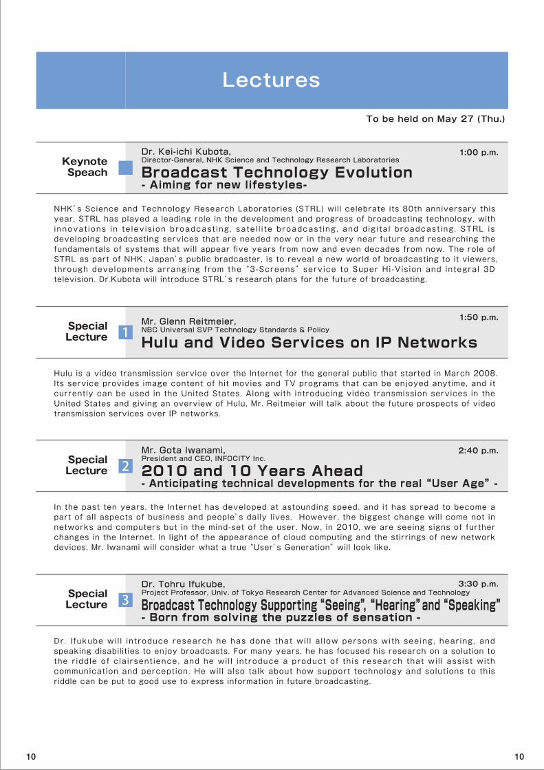
Lectures
NHK’s Science and Technology Research Laboratories (STRL) will celebrate its 80th anniversary this year. STRL has played a leading role in the development and progress of broadcasting technology, with innovat ions in te lev is ion broadcast ing , satel l i te broadcast ing , and dig i ta l broadcast ing . STRL is developing broadcasting services that are needed now or in the very near future and researching the fundamentals of systems that will appear five years from now and even decades from now. The role of STRL as part of NHK, Japan’s public bradcaster, is to reveal a new world of broadcasting to it viewers, through developments arranging from the “3-Screens” service to Super Hi-Vision and integral 3D television. Dr.Kubota will introduce STRL’s research plans for the future of broadcasting.
Hulu and Video Services on IP NetworksMr. Glenn Reitmeier, NBC Universal SVP Technology Standards & Policy
Hulu is a video transmission service over the Internet for the general public that started in March 2008. Its service provides image content of hit movies and TV programs that can be enjoyed anytime, and it currently can be used in the United States. Along with introducing video transmission services in the United States and giving an overview of Hulu, Mr. Reitmeier will talk about the future prospects of video transmission services over IP networks.
Broadcast Technology Evolution- Aiming for new lifestyles-
Dr. Kei-ichi Kubota, Director-General, NHK Science and Technology Research Laboratories
SpecialLecture
KeynoteSpeach
1
In the past ten years, the Internet has developed at astounding speed, and it has spread to become a part of all aspects of business and people’s daily lives. However, the biggest change will come not in networks and computers but in the mind-set of the user. Now, in 2010, we are seeing signs of further changes in the Internet. In light of the appearance of cloud computing and the stirrings of new network devices, Mr. Iwanami will consider what a true “User’s Generation” will look like.
SpecialLecture 2
To be held on May 27 (Thu.)
1:00 p.m.
1:50 p.m.
2:40 p.m.
Dr. I fukube wil l introduce research he has done that wil l al low persons with seeing, hearing, and speaking disabilities to enjoy broadcasts. For many years, he has focused his research on a solution to the r iddle of clairsent ience, and he wil l introduce a product of this research that wil l assist with communication and perception. He will also talk about how support technology and solutions to this riddle can be put to good use to express information in future broadcasting.
SpecialLecture 3
3:30 p.m.
2010 and 10 Years Ahead - Anticipating technical developments for the real “User Age” -
Mr. Gota Iwanami, President and CEO, INFOCITY Inc.
Broadcast Technology Supporting “Seeing”, “Hearing” and “Speaking”- Born from solving the puzzles of sensation -
Dr. Tohru Ifukube, Project Professor, Univ. of Tokyo Research Center for Advanced Science and Technology
10 10
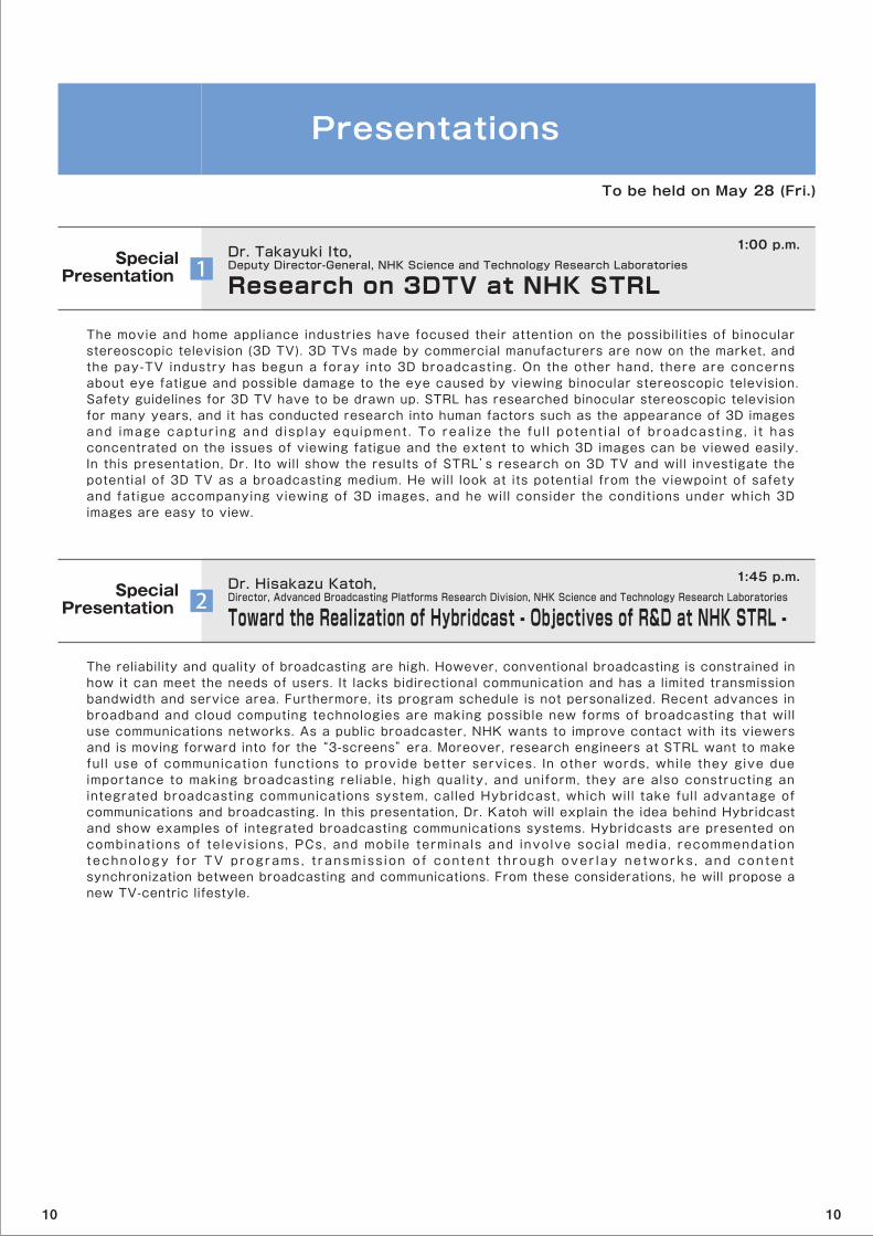
Presentations
The movie and home appliance industries have focused their attention on the possibilities of binocular stereoscopic television (3D TV). 3D TVs made by commercial manufacturers are now on the market, and the pay-TV industry has begun a foray into 3D broadcasting. On the other hand, there are concerns about eye fatigue and possible damage to the eye caused by viewing binocular stereoscopic television. Safety guidelines for 3D TV have to be drawn up. STRL has researched binocular stereoscopic television for many years, and it has conducted research into human factors such as the appearance of 3D images and image captur ing and display equipment . To real ize the ful l potent ia l o f broadcast ing , i t has concentrated on the issues of viewing fatigue and the extent to which 3D images can be viewed easily. In this presentation, Dr. Ito will show the results of STRL’s research on 3D TV and will investigate the potential of 3D TV as a broadcasting medium. He will look at its potential from the viewpoint of safety and fatigue accompanying viewing of 3D images, and he will consider the conditions under which 3D images are easy to view.
11:00 p.m.
To be held on May 28 (Fri.)
Research on 3DTV at NHK STRLDr. Takayuki Ito, Deputy Director-General, NHK Science and Technology Research LaboratoriesSpecial
Presentation
The reliability and quality of broadcasting are high. However, conventional broadcasting is constrained in how it can meet the needs of users. It lacks bidirectional communication and has a limited transmission bandwidth and service area. Furthermore, its program schedule is not personalized. Recent advances in broadband and cloud computing technologies are making possible new forms of broadcasting that will use communications networks. As a public broadcaster, NHK wants to improve contact with its viewers and is moving forward into for the “3-screens” era. Moreover, research engineers at STRL want to make full use of communication functions to provide better services. In other words, while they give due importance to making broadcasting reliable, high quality, and uniform, they are also constructing an integrated broadcasting communications system, called Hybridcast, which will take full advantage of communications and broadcasting. In this presentation, Dr. Katoh will explain the idea behind Hybridcast and show examples of integrated broadcasting communications systems. Hybridcasts are presented on combinat ions of televisions, PCs, and mobile terminals and involve social media, recommendation techno logy for TV programs , t ransmiss ion o f conten t through over lay ne tworks , and content synchronization between broadcasting and communications. From these considerations, he will propose a new TV-centric lifestyle.
21:45 p.m.
Toward the Realization of Hybridcast - Objectives of R&D at NHK STRL -Dr. Hisakazu Katoh, Director, Advanced Broadcasting Platforms Research Division, NHK Science and Technology Research LaboratoriesSpecial
Presentation
10 10

Research Presentation
Flexible Program Production System
Mr. Shinya Takeuchi, Advanced Broadcasting Platforms Research Division, NHK Science and Technology Research Laboratories
Over the years, broadcasting producers have relied on VCR tape. These days, however, hard disks and other forms of non-volatile memory have made it possible to make a file-based non-linear editing and program material transfer system on an IP network. STRL researchers are working to develop such a “flexible” program production system that could streamline the production workflow. We envision that program producers can easily manage large amounts of program materials and edit decision lists on the system. The system is scalable in terms of its image processing functions and capacity and makes effective use of the available resources. In his presentation, Mr. Takeuchi will review the current situation and problems of file-based systems and outline a new architecture of flexible program production. He will show a front-end interface developed on Web services and describe middleware based on grid computing, a back-end system that distributes the task of image processing among computers on a network, and a distributed file storage system with peer-to-peer technology. He will also explain the file system developed for fast MXF file editing and file transfer protocol over IP networks, which are key image processing technologies.
ResearchPresentation 1
STRL researchers envision Super Hi-Vision as the broadcasting system of the future. It will be a system that combines high image sensitivity and vivid realism, and they are moving forward with research and development of this system. Super Hi-Vision’s video images contain 33 million pixels (horizontal: 7680 pixels, vertical: 4320 pixels), which is 16 times the number of pixels in Hi-Vision. However, the prototype camera developed in 2004 used four image sensors (two for green, and one each for red and blue), each with only 8.3 million pixels but with equivalent resolution to that of a 33-million-pixel single chip color camera. To proceed with development of devices and for standardization of Super Hi-Vision, we urgently need a camera with a 33-million-pixel resolution for each of the red, green, and blue images. In his presentation, Mr. Yamashita will talk about a camera that has three 33-million-pixel CMOS image sensors, each measuring 2-1/2 inches. It is the first of its kind in the world. First, he will discuss the role of this camera in the development of Super Hi-Vision. Next, he will explain design plans for the camera, its device structure, and current performance. Finally, he will talk about the future development of the camera, which will include improving its practical features by making it more compact.
10:30 a.m.
A Full Resolution Super Hi-Vision Camera System
Mr. Takayuki Yamashita, Advanced Television Research Division, NHK Science and Technology Research LaboratoriesResearch
Presentation
10:55 a.m.
To be held on May 28 (Fri.)
2
Closed-captioned broadcasting is an important medium of information accessibility for hearing impaired and elderly persons. For many years, it was technologically difficult to provide closed-captions during live TV programs, but thanks to progress in speech recognition technology and special high-speed input keyboards, real-time closed-captioning of live programs such as news and sports is now possible. STRL engineers will continue to work on speech recognition technology to make live closed-captioning more efficient. In this speech, Mr. Homma will introduce the live captioning systems that are in use today, and then he will give an overview of a new system under development. The new system is a hybrid that combines the “direct method”, which input is the original program sound, and the “re-speak” method, which input requires the speech of the original program to be rephrased by a “re-speaker” in a quiet area. By improving the speech recognizer and its error correction system, researchers have made it possible for one or two correction operators to do live closed-captioning for simply produced news programs. He will also discuss STRL’s research aimed at improving spontaneous speech recognition for conversations in TV programs.
3Speech Recognition for Live Closed-Captioning
Mr. Shinichi Homma, Human and Information Science Research Division, NHK Science and Technology Research LaboratoriesResearch
Presentation
11:20 a.m.
10 10
Research Presentation
3:10 p.m.
To be held on May 28 (Fri.)
STRL has been developing ultra-high-sensitivity high-gain avalanche rushing amorphous photoconductor (HARP) imaging devices for cameras used to report breaking news at night. The HARP device achieves high sensitivity by exploiting an avalanche multiplication phenomenon that occurs in photoconductive film made from amorphous selenium (a-Se). However, the energy bandgap characteristics of a-Se cause the pho toe lec t r ic -convers ion effic iency to decrease for long wave leng th l i gh t ( i . e . , r ed ) , and the signal-to-noise ratio falls off. In addition, medical applications and science television programs require high sensitivity to near-infrared light and X-rays. In his report, Dr. Ohkawa will discuss a very efficient HARP film that combines an avalanche mult iplication layer of a-Se with a new photosensit ive layer having high photoelectric-conversion efficiency for the whole spectrum of visible light. He will discuss the means of controlling electric field in this film and the features of the prototype. He will also outline a fiber optic plate (FOP)-HARP pickup tube that can be connected to an image intensifier sensitive to near-infrared light or to an X-ray fluorescent screen with low optical loss. Finally, he will show images taken with near-infrared light and X-rays.
ResearchPresentation 5
Practical video holography of 3D objects will require a high-definition spatial modulator with a fast response. STRL researchers have devised an ultra-high-definition light modulation device that is driven by spin transfer switching. The device exploits the magneto-optical Kerr effect in which the plane of polarization of light changes in response to the magnetization direction of a magnetic material and spin transfer switching in which the magnetization direction reverses by means of applying an electric current. In his report, Dr. Machida will discuss how the device’s light modulation factor can be improved by using perpendicular magnetization. He will also talk about a basic experiment showing that it is possible to align several magnetizations in one pixel and that multi-stage light modulation can be carried out by means of space division. He will also describe a perpendicular magnetic tunnel junction device designed to reduce drive current. For low current driving, it is necessary to use a magnesium oxide (MgO) barrier in the tunnel junction in order to crystall ize with a MgO (001)-oriented texture. The deposition conditions and the structure of the layers had to be improved to make this possible and X-ray diffraction measurements revealed a peak due to highly oriented MgO (001). He will also outline basic light diffraction experiments on holography.
ResearchPresentation 6
3:55 p.m.
Smoke and flames make it impossible to see what things are like in the fire or behind it. A camera that could see through these obstacles would naturally be useful for saving human lives as well as for news reporting. Mr. Kamoda has been developing a TV camera that picks up millimeter waves instead of visible light waves. Millimeter waves can penetrate smoke, flames, and wood. The camera emits 60-GHz millimeter waves onto the objects to be imaged. The receiver antenna is electronically scanned to the left and right and up and down, and the camera produces a two-dimensional image from the received waves that were reflected off the object. The frame frequency of the previous prototype was very low, and it could not take images of moving objects. The new camera has a higher frame frequency. Mr. Kamoda will start by describing the operation principle and system. After that, he will discuss the reflectarray antenna, which he designed, and the results of experimental evaluations. He will also explain signal processing of the received millimeter waves to produce the image. The imaging experiments yielded a frame frequency of 2.3 Hz, which is more than 23 times the frame frequency of the previous prototype.
ResearchPresentation 4
2:45 p.m.
Millimeter-wave TV Camera - Active Millimeter-wave Imaging System -
Mr. Hirokazu Kamoda, Broadcasting Networks Research Division, NHK Science and Technology Research Laboratories
Improving the Picture Quality of Ultra-high-sensitivity HARP Imaging Devices
Dr. Yuji Ohkawa, Image and Storage Devices Research Division, NHK Science and Technology Research Laboratories
An Ultra-fine Spatial Light Modulation Device
Dr. Kenji Machida, Display and Functional Devices Research Division, NHK Science and Technology Research Laboratories
10 10
Events
Nattoku Terebi Jyuku~Let's learn how TV works~
You can learn more about how TV works. STRL researchers will explain state-of-the-art broadcasting technology in easy-to-understand terms for older elementary school students, junior high school students, and their parents. The lectures are follows:
○ It captures even the fastest movements ‒ "Ultrahigh-speed imaging technology"
○ It delivers beautiful images to your home - "Image compression technology”
○ It writes down what you say - "Speech recognition technology"
(Seating is limited. If you do not have a reservation, you will be seated on a first-come first-served basis. You can reserve a seat on our web site.)
Guided Tours
STRL researchers will provide guided tours of the Open House to groups of about seven members each. They wil l show places of interest in the laboratory and explain the exhibits.
(The number of participants is limited. For those without reservations, tours will be offered on a first come, first served basis.You can reserve a tour on our web site.)
Stamp Rally
Let’s get together to collect stamps in the Open House. We wil l give presents to people who get all stamps. People will also get "NHK netclub" points.
(The number of presents is limited. They will be given out on a first-come, first-served basis.)
To be held on May 29 (Sat.) and May 30 (Sun.)
1:30~2:30 p.m.
10:20 a.m.~3:20 p.m. (16 times)
10:00 a.m. to 30 minute before closing
For details of the events and making reservations, please visit our homepage.ht tp://www.nhk.or . jp/s tr l /
10 10
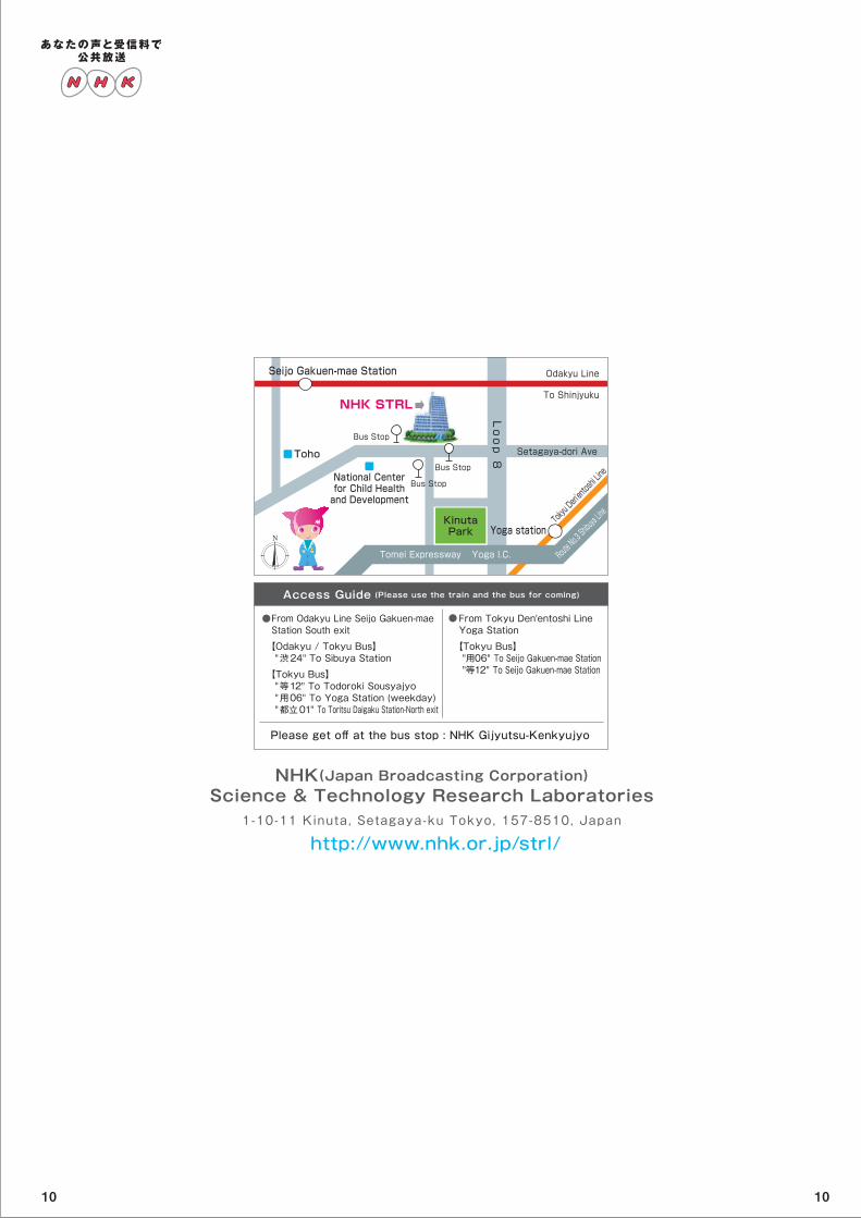
NHK(Japan Broadcasting Corporation)Science & Technology Research Laboratories
1-10-11 Kinuta, Setagaya-ku Tokyo, 157-8510, Japan
http://www.nhk.or.jp/strl/
From Odakyu Line Seijo Gakuen-mae Station South exit
【Odakyu / Tokyu Bus】 "渋24" To Sibuya Station
【Tokyu Bus】 "等12" To Todoroki Sousyajyo "用06" To Yoga Station (weekday) "都立01" To Toritsu Daigaku Station-North exit
From Tokyu Den'entoshi Line Yoga Station
【Tokyu Bus】 "用06" To Seijo Gakuen-mae Station "等12" To Seijo Gakuen-mae Station
Please get off at the bus stop : NHK Gijyutsu-Kenkyujyo
Access Guide (Please use the train and the bus for coming)
●●
Tokyu Den'entoshi Line
首都高速
Setagaya-dori Ave
Loop 8
Seijo Gakuen-mae Station
To Shinjyuku
Odakyu Line
Bus Stop
Bus StopToho
National Centerfor Child Healthand Development
KinutaPark Yoga station
Yoga I.C.
Bus Stop
NHK STRL
Route No.3 Shibuya Line
Tomei Expressway
10 10