pt1 coupling
TRANSCRIPT
CONTENTS
PT1-1
PT
Co
mp
on
en
t R
efe
ren
ce
Gu
ide
Co
up
ling
sC
lutc
hes
an
d B
rake
sF
LE
XID
YN
EF
luid
Co
up
ling
sT
OR
QU
E-T
AM
ER
Bu
shin
gs
Couplings
Features / Benefits PARA-FLEX® . . . . . . . . . . . . . . . . . . . . . . . . . . . . . . . . . . . . . . . . . . . . . PT1-2 PARA-FLEX High Speed Flywheel . . . . . . . . . . . . . . . . . . . . . . . . . . . PT1-29 D-FLEX® . . . . . . . . . . . . . . . . . . . . . . . . . . . . . . . . . . . . . . . . . . . . . . . PT1-35 GRID-LIGN® . . . . . . . . . . . . . . . . . . . . . . . . . . . . . . . . . . . . . . . . . . . . PT1-48 Gear Coupling. . . . . . . . . . . . . . . . . . . . . . . . . . . . . . . . . . . . . . . . . . . PT1-60 Chain Coupling . . . . . . . . . . . . . . . . . . . . . . . . . . . . . . . . . . . . . . . . . . PT1-65 Power Plus . . . . . . . . . . . . . . . . . . . . . . . . . . . . . . . . . . . . . . . . . . . . . PT1-76
Specification PARA-FLEX® . . . . . . . . . . . . . . . . . . . . . . . . . . . . . . . . . . . . . . . . . . . . . PT1-4 D-FLEX® . . . . . . . . . . . . . . . . . . . . . . . . . . . . . . . . . . . . . . . . . . . . . . . PT1-37 GRID-LIGN® . . . . . . . . . . . . . . . . . . . . . . . . . . . . . . . . . . . . . . . . . . . . PT1-50 Gear Coupling. . . . . . . . . . . . . . . . . . . . . . . . . . . . . . . . . . . . . . . . . . . PT1-62 Chain Coupling . . . . . . . . . . . . . . . . . . . . . . . . . . . . . . . . . . . . . . . . . . PT1-72 Power Plus . . . . . . . . . . . . . . . . . . . . . . . . . . . . . . . . . . . . . . . . . . . . . PT1-72How To Order PARA-FLEX® . . . . . . . . . . . . . . . . . . . . . . . . . . . . . . . . . . . . . . . . . . . . . PT1-4 D-FLEX® . . . . . . . . . . . . . . . . . . . . . . . . . . . . . . . . . . . . . . . . . . . . . . . PT1-37 GRID-LIGN® . . . . . . . . . . . . . . . . . . . . . . . . . . . . . . . . . . . . . . . . . . . . PT1-50 Gear Coupling. . . . . . . . . . . . . . . . . . . . . . . . . . . . . . . . . . . . . . . . . . . PT1-62 Chain Coupling . . . . . . . . . . . . . . . . . . . . . . . . . . . . . . . . . . . . . . . . . . PT1-72 Power Plus . . . . . . . . . . . . . . . . . . . . . . . . . . . . . . . . . . . . . . . . . . . . . PT1-74Nomenclature PARA-FLEX® . . . . . . . . . . . . . . . . . . . . . . . . . . . . . . . . . . . . . . . . . . . . . PT1-5 D-FLEX® . . . . . . . . . . . . . . . . . . . . . . . . . . . . . . . . . . . . . . . . . . . . . . . PT1-37 GRID-LIGN® . . . . . . . . . . . . . . . . . . . . . . . . . . . . . . . . . . . . . . . . . . . . PT1-51 Gear Coupling. . . . . . . . . . . . . . . . . . . . . . . . . . . . . . . . . . . . . . . . . . . PT1-62 Chain Coupling . . . . . . . . . . . . . . . . . . . . . . . . . . . . . . . . . . . . . . . . . . PT1-72 POLY-DISC® . . . . . . . . . . . . . . . . . . . . . . . . . . . . . . . . . . . . . . . . . . . . PT1-63 Rigid . . . . . . . . . . . . . . . . . . . . . . . . . . . . . . . . . . . . . . . . . . . . . . . . . . PT1-63Selection/Dimensions PARA-FLEX® . . . . . . . . . . . . . . . . . . . . . . . . . . . . . . . . . . . . . . . . . . . . . PT1-6 High Speed, TAPER-LOCK . . . . . . . . . . . . . . . . . . . . . . . . . . . . . . . . . PT1-30 D-FLEX® . . . . . . . . . . . . . . . . . . . . . . . . . . . . . . . . . . . . . . . . . . . . . . . PT1-38 GRID-LIGN® . . . . . . . . . . . . . . . . . . . . . . . . . . . . . . . . . . . . . . . . . . . . PT1-52 Gear Coupling. . . . . . . . . . . . . . . . . . . . . . . . . . . . . . . . . . . . . . . . . . . PT1-63 Chain Coupling . . . . . . . . . . . . . . . . . . . . . . . . . . . . . . . . . . . . . . . . . . PT1-66 POLY-DISC® . . . . . . . . . . . . . . . . . . . . . . . . . . . . . . . . . . . . . . . . . . . . PT1-73 Rigid . . . . . . . . . . . . . . . . . . . . . . . . . . . . . . . . . . . . . . . . . . . . . . . . . . PT1-74
Modifications/Accessories . . . . . . . . . . . . . . . . . . . . . . . . . . . . . . . . . . . . . PT1-81
Engineering/Technical . . . . . . . . . . . . . . . . . . . . . . . . . . . . . . . . . . . . . . . . PT1-83
Part Number Index . . . . . . . . . . . . . . . . . . . . . . . . . . . . . . . . . . . . . . . . . . INDEX-1
Keyword Index . . . . . . . . . . . . . . . . . . . . . . . . . . . . . . . . . . . . . . . . . . . . INDEX-63
PT1-2
FEATURES/BENEFITS
PT
Co
mp
on
en
t R
efe
ren
ce G
uid
eC
ou
plin
gs
Clu
tch
es an
d B
rakesF
LE
XID
YN
EF
luid
Co
up
ling
sT
OR
QU
E-TA
ME
RB
ush
ing
s
Finished Bore Flange Design• Extra bore capacity
• Accommodates larger shaft diameters
• Allows for smaller coupling selection
• Two setscrews at 65°
• Precision alignment flats
• Ductile iron flange for clearance or interfer ence fits
TAPER-LOCK Flange Design• Reversible flanges for H or F style mounting on
sizes PX50-PX120
• Uses standard TAPER-LOCK bushings for wide range of bores
Five-Year Limited Warranty• Dependable product performance
• 40+ years application experience
• Warranty includes sizes PX40 thru PX200
No Lubrication• Less maintenance
Visual Inspection• Saves time
ATEX Approved• Documents available
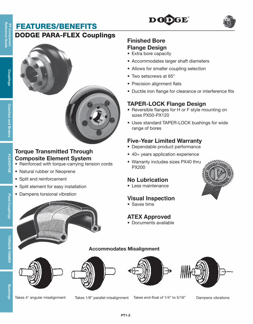
DODGE PARA-FLEX Couplings
• Reinforced with torque-carrying tension cords
• Natural rubber or Neoprene
• Split end reinforcement
• Split element for easy installation
• Dampens torsional vibration
Torque Transmitted Through Composite Element System
Accommodates Misalignment
Takes 4° angular misalignment Takes 1/8” parallel misalignment Takes end-float of 1/4” to 5/16” Dampens vibrations
PT1-3
PT
Co
mp
on
en
t R
efe
ren
ce
Gu
ide
Co
up
ling
sC
lutc
hes
an
d B
rake
sF
LE
XID
YN
EF
luid
Co
up
ling
sT
OR
QU
E-T
AM
ER
Bu
shin
gs
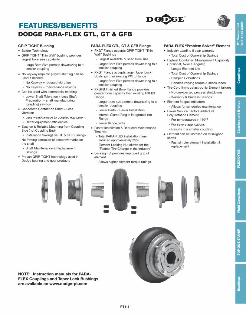
FEATURES/BENEFITSDODGE PARA-FLEX GTL, GT & GFB
GRIP TIGHT Bushing Baldor Technology
GRIP TIGHT “Thin Wall” bushing provides largest bore size capability
- Large Bore Size permits downsizing to a smaller coupling
No keyway required (keyed shafting can be used if desired)- No Keyway = reduced vibration- No Keyway = maintenance savings
Can be used with commercial shafting
- Lower Shaft Tolerance = Less Shaft Preparation = shaft manufacturing (grinding) savings
Concentric Contact on Shaft = Less vibration- Less wear/damage to coupled equipment- Better equipment efficiencies
Easy on & Reliable Mounting from Coupling Side (not Coupling End)- Installation Savings vs. TL & QD Bushings
No fretting corrosion or setscrew marks on the shaft- Shaft Maintenance & Replacement
Savings
Proven GRIP TIGHT technology used in Dodge bearing and gear products
PARA-FLEX GTL, GT & GFB Flange PXGT Flange accepts GRIP TIGHT “Thin
Wall” Bushings- Largest available bushed bore size
- Larger Bore Size permits downsizing to a smaller coupling
PXGT Flange accepts larger Taper Lock Bushings than existing PXTL Flange- Larger Bore Size permits downsizing to a
smaller coupling
PXGFB Finished Bore Flange provides greater bore capacity than existing PXFBX Flange- Larger bore size permits downsizing to a
smaller coupling- Fewer Parts = Easier Installation- Internal Clamp Ring is integrated into
Flange- Fewer flange blots
Faster Installation & Reduced Maintenance Time via:- Total PARA-FLEX installation time
reduced approximately 35%- Element Locking Nut allows for the
“Fastest Tire Change in the Industry”
Locking nut provides improved grip of element- Allows higher element torque ratings
PARA-FLEX “Problem Solver” Element Industry Leading 5 year warranty
- Total Cost of Ownership Savings
Highest Combined Misalignment Capability (Torsional, Axial & Angular)- Longer Element Life
- Total Cost of Ownership Savings- Dampens vibrations
- Handles varying torque & shock loads
Tire Cord limits catastrophic Element failures
- No unexpected process shutdowns
- Warranty & Process Savings
Element fatigue indicators
- Allows for scheduled maintenance
Lower Service Factors adders vs. Polyurethane Element- For temperatures > 150ºF
- For severe applications
- Results in a smaller coupling
Element can be installed on misaligned shafts- Fast simpler element installation &
replacement
NOTE: Instruction manuals for PARA-FLEX Couplings and Taper Lock Bushings are available on www.dodge-pt.com
PT1-4
SPECIFICATION/HOW TO ORDER/NOMENCLATURE
PT
Co
mp
on
en
t R
efe
ren
ce G
uid
eC
ou
plin
gs
Clu
tch
es an
d B
rakesF
LE
XID
YN
EF
luid
Co
up
ling
sT
OR
QU
E-TA
ME
RB
ush
ing
s
FEATURES/BENEFITS PAGE PT1-2
SELECTION/DIMENSIONS PAGE PT1-6
MODIFICATION/ACCESSORIES PAGE PT1-81
ENGINEERING/TECHNICAL PAGE PT1-83
PARA-FLEXSPECIFICATIONPARA-FLEX Couplings employ a molded, non-lubricated elastomeric flexing member loaded in shear. The flexible member is compounded natural or neoprene rubber with textile cord reinforcement throughout and has an extra layer of reinforcement adjacent to the split for added durability. The compound of natural rubber element shall be suitable for operation in ambient temperature from -45°F to +180°F; Neoprene -40°F to +210°F.
The flexible element is attached by clamping between axially separable rings with exposed SAE grade 8 cap screws. The couplings are designed to be capable of accommodating combined misalignments of 4° angular, 1/8” parallel, and 5/16” end float at the full rating of the coupling without restricting the rating or life of the coupling. The flexible element must be replaceable without disturbing the coupled equipment and without the requirement for realignment.
The coupling assemblies have optional methods of attachment to the shaft including but not limited to: clearance fit, interference fit and GRIP TIGHT Bushings or TAPER-LOCK bushings. Clearance fits and interference fits are supplied with an industry standard keyway and two set screws, one over the key and one at 65°.
Spacer Couplings consist of two hubs and a pre-assembled center assembly. The center assembly is readily removable to facilitate maintenance on pumps or other connected equipment and must be replaceable without disturbing the coupled equipment and without realignment.
1 PX40: 4° angular, 1/16” parallel, 3/16” end float.
2 PX110: 4° angular, 1/8” parallel, 1/4” end float.
3 PH & PF: 1° angular, 1/16” parallel, 3/16” end float.
PARA-FLEX Couplings are static conductive.
HOW TO ORDERStandard couplings consist of: Spacer Couplings consist of:
(2) Flange Assemblies (2) Hubs
(1) Flexible Element
(2) Bushings (TL or GT only)
(1) Center Assembly
PT1-5
PT
Co
mp
on
en
t R
efe
ren
ce
Gu
ide
Co
up
ling
sC
lutc
hes
an
d B
rake
sF
LE
XID
YN
EF
luid
Co
up
ling
sT
OR
QU
E-T
AM
ER
Bu
shin
gs
FEATURES/BENEFITS PAGE PT1-2
SELECTION/DIMENSIONS PAGE PT1-6
MODIFICATION/ACCESSORIES PAGE PT1-81
ENGINEERING/TECHNICAL PAGE PT1-83
SPECIFICATION/HOW TO ORDER/NOMENCLATURE
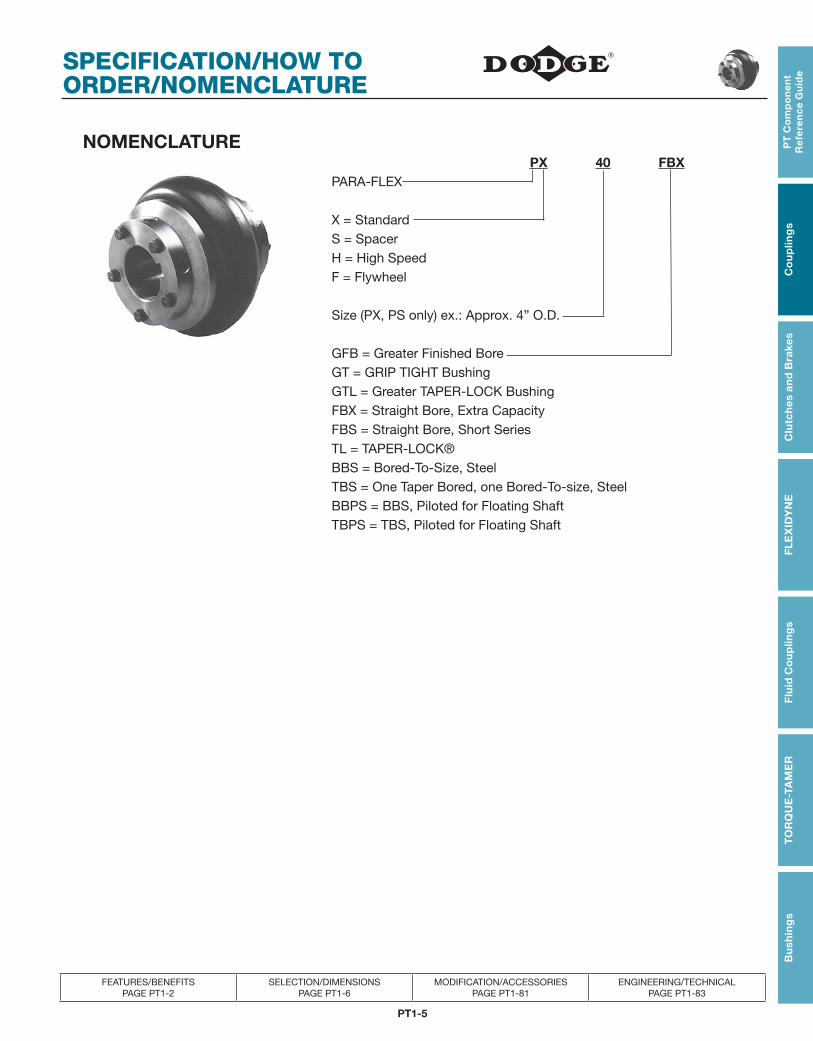
NOMENCLATURE PX 40 FBXPARA-FLEX
X = StandardS = SpacerH = High SpeedF = Flywheel
Size (PX, PS only) ex.: Approx. 4” O.D.
GFB = Greater Finished BoreGT = GRIP TIGHT BushingGTL = Greater TAPER-LOCK BushingFBX = Straight Bore, Extra CapacityFBS = Straight Bore, Short SeriesTL = TAPER-LOCK®BBS = Bored-To-Size, SteelTBS = One Taper Bored, one Bored-To-size, SteelBBPS = BBS, Piloted for Floating ShaftTBPS = TBS, Piloted for Floating Shaft
PT1-6
SELECTION/DIMENSIONS
PT
Co
mp
on
en
t R
efe
ren
ce G
uid
eC
ou
plin
gs
Clu
tch
es an
d B
rakesF
LE
XID
YN
EF
luid
Co
up
ling
sT
OR
QU
E-TA
ME
RB
ush
ing
s
FEATURES/BENEFITS PAGE PT1-2
SPECIFICATION/HOW TO ORDER PAGE PT1-4
MODIFICATION/ACCESSORIES PAGE PT1-81
ENGINEERING/TECHNICAL PAGE PT1-83
PARA-FLEX GFB
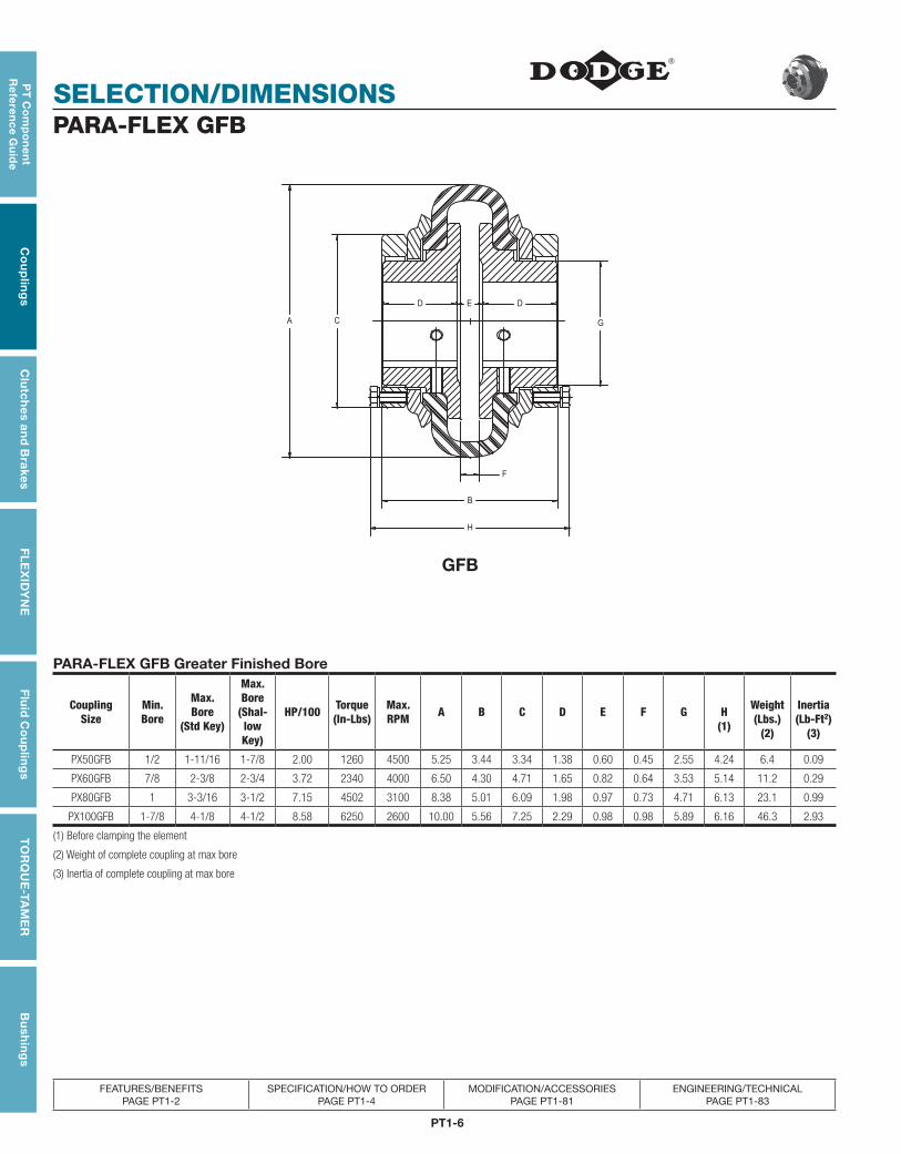
PARA-FLEX GFB Greater Finished Bore
Coupling Size
Min. Bore
Max. Bore
(Std Key)
Max. Bore
(Shal- low Key)
HP/100 Torque (In-Lbs)
Max. RPM A B C D E F G H
(1)
Weight (Lbs.)
(2)
Inertia (Lb-Ft2)
(3)
PX50GFB 1/2 1-11/16 1-7/8 2.00 1260 4500 5.25 3.44 3.34 1.38 0.60 0.45 2.55 4.24 6.4 0.09
PX60GFB 7/8 2-3/8 2-3/4 3.72 2340 4000 6.50 4.30 4.71 1.65 0.82 0.64 3.53 5.14 11.2 0.29
PX80GFB 1 3-3/16 3-1/2 7.15 4502 3100 8.38 5.01 6.09 1.98 0.97 0.73 4.71 6.13 23.1 0.99
PX100GFB 1-7/8 4-1/8 4-1/2 8.58 6250 2600 10.00 5.56 7.25 2.29 0.98 0.98 5.89 6.16 46.3 2.93
(1) Before clamping the element
(2) Weight of complete coupling at max bore
(3) Inertia of complete coupling at max bore
GFB
PT1-7
PT
Co
mp
on
en
t R
efe
ren
ce
Gu
ide
Co
up
ling
sC
lutc
hes
an
d B
rake
sF
LE
XID
YN
EF
luid
Co
up
ling
sT
OR
QU
E-T
AM
ER
Bu
shin
gs
SELECTION/DIMENSIONS
FEATURES/BENEFITS PAGE PT1-2
SPECIFICATION/HOW TO ORDER PAGE PT1-4
MODIFICATION/ACCESSORIES PAGE PT1-81
ENGINEERING/TECHNICAL PAGE PT1-83
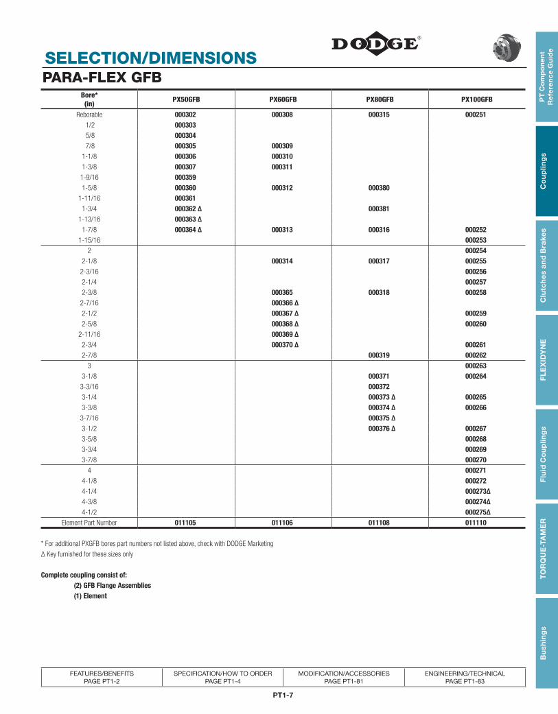
PARA-FLEX GFBBore*(in) PX50GFB PX60GFB PX80GFB PX100GFB
Reborable 000302 000308 000315 000251 1/2 000303 5/8 000304 7/8 000305 000309
1-1/8 000306 0003101-3/8 000307 0003111-9/16 0003591-5/8 000360 000312 000380
1-11/16 0003611-3/4 000362 ∆ 000381
1-13/16 000363 ∆1-7/8 000364 ∆ 000313 000316 000252
1-15/16 0002532 000254
2-1/8 000314 000317 0002552-3/16 0002562-1/4 0002572-3/8 000365 000318 000258
2-7/16 000366 ∆2-1/2 000367 ∆ 0002592-5/8 000368 ∆ 000260
2-11/16 000369 ∆2-3/4 000370 ∆ 0002612-7/8 000319 000262
3 0002633-1/8 000371 000264
3-3/16 0003723-1/4 000373 ∆ 0002653-3/8 000374 ∆ 000266
3-7/16 000375 ∆3-1/2 000376 ∆ 0002673-5/8 0002683-3/4 0002693-7/8 000270
4 0002714-1/8 0002724-1/4 000273∆4-3/8 000274∆4-1/2 000275∆
Element Part Number 011105 011106 011108 011110
* For additional PXGFB bores part numbers not listed above, check with DODGE Marketing
∆ Key furnished for these sizes only
Complete coupling consist of: (2) GFB Flange Assemblies (1) Element
PT1-8
SELECTION/DIMENSIONS
PT
Co
mp
on
en
t R
efe
ren
ce G
uid
eC
ou
plin
gs
Clu
tch
es an
d B
rakesF
LE
XID
YN
EF
luid
Co
up
ling
sT
OR
QU
E-TA
ME
RB
ush
ing
s
FEATURES/BENEFITS PAGE PT1-2
SPECIFICATION/HOW TO ORDER PAGE PT1-4
MODIFICATION/ACCESSORIES PAGE PT1-81
ENGINEERING/TECHNICAL PAGE PT1-83
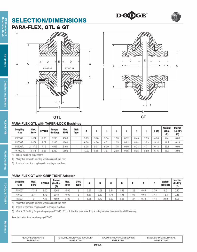
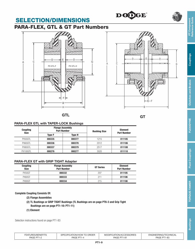
PARA-FLEX, GTL & GT
PARA-FLEX GTL with TAPER-LOCK Bushings
Coupling Size
Max. Bore HP/100 Torque
(In-Lbs)Max. RPM
DWG Type A B C D E F G H (1)
Weight (Lbs) (2)
Inertia (Lb-Ft2)
(3)
PX50GTL 1-1/4 2.00 1260 4500 1 5.25 3.60 3.34 1.50 0.52 0.45 2.55 4.24 6.4 0.89
PX60GTL 2-1/8 3.72 2340 4000 1 6.50 4.30 4.71 1.25 0.82 0.64 3.53 5.14 11.2 0.29
PX80GTL 2-11/16 7.15 4502 3100 1 8.38 5.01 6.09 1.75 0.89 0.73 4.71 6.13 23.1 0.99
PX100GTL 3-1/4 8.58 6250 2600 1 10.00 5.55 7.67 2.00 0.95 0.95 5.89 6.16 46.3 2.93
(1) Before clamping the element
(2) Weight of complete coupling with bushing at max bore
(3) Inertia of complete coupling with bushing at max bore
PARA-FLEX GT with GRIP TIGHT Adapter
Coupling Size
Max. Bore HP/100
Torque(in-Lbs)
(3)
Max. RPM
DWG Type A B C D E F G Weight
(Lbs) (1)
Inertia(lb-Ft2)
(2)
PX50GT 1-7/16 2.00 1260 4500 2 5.25 4.58 3.34 1.62 1.22 0.45 2.39 6.5 0.10
PX60GT 2-/4 3.72 2340 4000 2 6.50 5.50 4.71 1.93 1.50 0.64 3.43 12.4 0.33
PX80GT 3 7.15 4502 3100 2 8.38 6.49 6.09 2.56 1.37 0.73 4.44 24.9 1.05
(1) Weight of complete coupling with bushing at max bore
(2) Inertia of complete coupling with bushing at max bore
(3) Check GT Bushing Torque rating on page PT1-10 : PT1-11. Use the lower max. Torque rating between the element and GT bushing,
Selection instructions found on page PT1-83
GTL GT
PT1-9
PT
Co
mp
on
en
t R
efe
ren
ce
Gu
ide
Co
up
ling
sC
lutc
hes
an
d B
rake
sF
LE
XID
YN
EF
luid
Co
up
ling
sT
OR
QU
E-T
AM
ER
Bu
shin
gs
SELECTION/DIMENSIONS
FEATURES/BENEFITS PAGE PT1-2
SPECIFICATION/HOW TO ORDER PAGE PT1-4
MODIFICATION/ACCESSORIES PAGE PT1-81
ENGINEERING/TECHNICAL PAGE PT1-83
PARA-FLEX GTL with TAPER-LOCK Bushings
Coupling Size
Flange Assembly Part Number Bushing Size Element
Part NumberType F Type H
PX50GTL 000335 000377 1215 011105
PX60GTL 000336 000378 2012 011106
PX80GTL 000337 000379 2517 011108
PX100GTL 000276 000277 3020 011110
PARA-FLEX GT with GRIP TIGHT AdapterCoupling
Size Flange Assembly
Part Number GT Series Element Part Number
PX50GT 000332 207 011105
PX60GT 000333 211 011106
PX80GT 000334 215 011108
Complete Coupling Consists Of:
(2) Flange Assemblies
(2) TL Bushings or GRIP TIGHT Bushings (TL Bushings are on page PT6-3 and Grip Tight Bushings are on page PT1-10: PT1-11)
(1) Element
Selection instructions found on page PT1-83
PARA-FLEX, GTL & GT Part Numbers
GTL GT
PT1-10
SELECTION/DIMENSIONS
PT
Co
mp
on
en
t R
efe
ren
ce G
uid
eC
ou
plin
gs
Clu
tch
es an
d B
rakesF
LE
XID
YN
EF
luid
Co
up
ling
sT
OR
QU
E-TA
ME
RB
ush
ing
s
FEATURES/BENEFITS PAGE PT1-2
SPECIFICATION/HOW TO ORDER PAGE PT1-4
MODIFICATION/ACCESSORIES PAGE PT1-81
ENGINEERING/TECHNICAL PAGE PT1-83
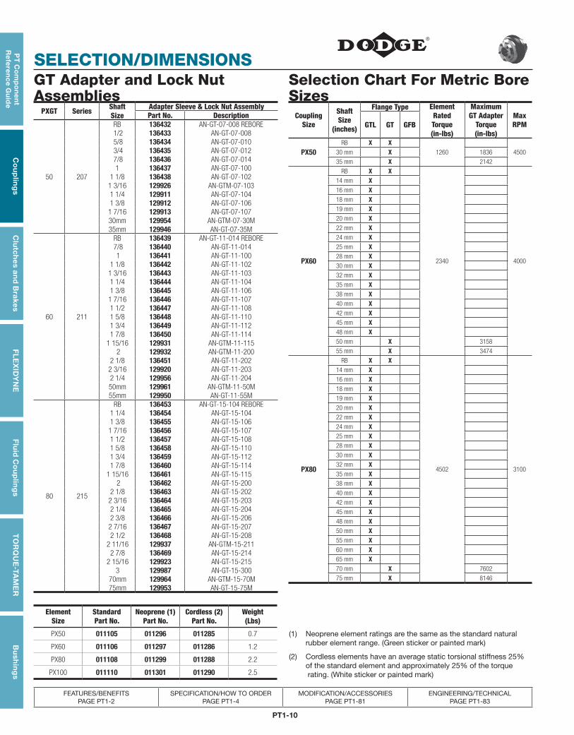
PXGT Series ShaftSize
Adapter Sleeve & Lock Nut AssemblyPart No. Description
50 207
RB 136432 AN-GT-07-008 REBORE 1/2 136433 AN-GT-07-008 5/8 136434 AN-GT-07-010 3/4 136435 AN-GT-07-012 7/8 136436 AN-GT-07-014
1 136437 AN-GT-07-1001 1/8 136438 AN-GT-07-1021 3/16 129926 AN-GTM-07-1031 1/4 129911 AN-GT-07-1041 3/8 129912 AN-GT-07-1061 7/16 129913 AN-GT-07-10730mm 129954 AN-GTM-07-30M 35mm 129946 AN-GT-07-35M
60 211
RB 136439 AN-GT-11-014 REBORE 7/8 136440 AN-GT-11-014 1 136441 AN-GT-11-100
1 1/8 136442 AN-GT-11-1021 3/16 136443 AN-GT-11-1031 1/4 136444 AN-GT-11-1041 3/8 136445 AN-GT-11-1061 7/16 136446 AN-GT-11-1071 1/2 136447 AN-GT-11-1081 5/8 136448 AN-GT-11-1101 3/4 136449 AN-GT-11-1121 7/8 136450 AN-GT-11-114
1 15/16 129931 AN-GTM-11-115 2 129932 AN-GTM-11-200
2 1/8 136451 AN-GT-11-2022 3/16 129920 AN-GT-11-2032 1/4 129956 AN-GT-11-20450mm 129961 AN-GTM-11-50M 55mm 129950 AN-GT-11-55M
80 215
RB 136453 AN-GT-15-104 REBORE1 1/4 136454 AN-GT-15-104 1 3/8 136455 AN-GT-15-1061 7/16 136456 AN-GT-15-1071 1/2 136457 AN-GT-15-1081 5/8 136458 AN-GT-15-1101 3/4 136459 AN-GT-15-1121 7/8 136460 AN-GT-15-114
1 15/16 136461 AN-GT-15-115 2 136462 AN-GT-15-200
2 1/8 136463 AN-GT-15-2022 3/16 136464 AN-GT-15-2032 1/4 136465 AN-GT-15-2042 3/8 136466 AN-GT-15-2062 7/16 136467 AN-GT-15-2072 1/2 136468 AN-GT-15-208
2 11/16 129937 AN-GTM-15-2112 7/8 136469 AN-GT-15-214
2 15/16 129923 AN-GT-15-2153 129987 AN-GT-15-300
70mm 129964 AN-GTM-15-70M 75mm 129953 AN-GT-15-75M
GT Adapter and Lock Nut Assemblies
CouplingSize
ShaftSize
(inches)
Flange Type ElementRatedTorque(in-lbs)
MaximumGT Adapter
Torque(in-lbs)
MaxRPMGTL GT GFB
PX50RB X X
1260 450030 mm X 1836
35 mm X 2142
PX60
RB X X
2340 4000
14 mm X16 mm X18 mm X19 mm X20 mm X22 mm X24 mm X25 mm X28 mm X30 mm X32 mm X35 mm X38 mm X40 mm X42 mm X45 mm X48 mm X50 mm X 3158
55 mm X 3474
PX80
RB X X
4502 3100
14 mm X16 mm X18 mm X19 mm X20 mm X22 mm X24 mm X25 mm X28 mm X30 mm X32 mm X35 mm X38 mm X40 mm X42 mm X45 mm X48 mm X50 mm X55 mm X60 mm X65 mm X70 mm X 7602
75 mm X 8146
Selection Chart For Metric Bore Sizes
Element Size
Standard Part No.
Neoprene (1)
Part No. Cordless (2)
Part No. Weight (Lbs)
PX50 011105 011296 011285 0.7
PX60 011106 011297 011286 1.2
PX80 011108 011299 011288 2.2
PX100 011110 011301 011290 2.5
(1) Neoprene element ratings are the same as the standard natural rubber element range. (Green sticker or painted mark)
(2) Cordless elements have an average static torsional stiffness 25% of the standard element and approximately 25% of the torque rating. (White sticker or painted mark)
PT1-11
PT
Co
mp
on
en
t R
efe
ren
ce
Gu
ide
Co
up
ling
sC
lutc
hes
an
d B
rake
sF
LE
XID
YN
EF
luid
Co
up
ling
sT
OR
QU
E-T
AM
ER
Bu
shin
gs
SELECTION/DIMENSIONS
FEATURES/BENEFITS PAGE PT1-2
SPECIFICATION/HOW TO ORDER PAGE PT1-4
MODIFICATION/ACCESSORIES PAGE PT1-81
ENGINEERING/TECHNICAL PAGE PT1-83
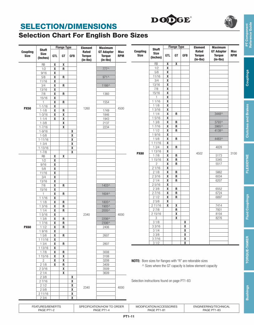
CouplingSize
Shaft Size
(Inches)
Flange Type Element Rated Torque(in-lbs)
Maximum GT Adapter
Torque(in-lbs)
MaxRPMGTL GT GFB
PX50
RB X X
1260 4500
1/2 X R 777^ 9/16 X 5/8 X R 971^
11/16 X3/4 X R 1166^
13/16 X7/8 X R 1360
15/16 X1 X R 1554
1-1/16 X1-1/8 X R 17491-3/16 X X 18461-1/4 X X 19431-3/8 X 21371-7/16 X 22341-9/16 X1-5/8 X
1-11/16 X1-3/4 X
1-13/16 X1-7/8 X
PX60
RB X X
2340 4000
1/2 X 9/16 X 5/8 X
11/16 X 3/4 X
13/16 X 7/8 X R 1403^
15/16 X1 X R 1604^
1 1/16 X1 1/8 X R 1805^
1 3/16 X R 1905^1 1/4 X R 2005^
1 5/16 X1 3/8 X R 2206^
1 7/16 X R 2306^1 1/2 X R 2406
1 9/16 X1 5/8 X R 2607
1 11/16 X1 3/4 X R 2807
1 13/16 X1 7/8 X R 3008
1 15/16 X X 31082 X X 3208
2 1/8 X R 34092 3/16 X 35092 1/4 X 36092 3/8 X
2340 4000
2 7/16 X2 1/2 X2 5/8 X
2 11/16 X2 3/4 X
CouplingSize
Shaft Size
(Inches)
Flange Type Element Rated Torque(in-lbs)
Maximum GT Adapter
Torque(in-lbs)
MaxRPMGTL GT GFB
PX80
RB X X
4502 3100
1/2 X 5/8 X
11/16 X 3/4 X
13/16 X7/8 X
15/16 X 1 X
1 1/16 X1 1/8 X
1 3/16 X1 1/4 X R 3448^1 5/16 X1 3/8 X R 3793^
1 7/16 X R 3965^1 1/2 X R 4138^1 9/16 X1 5/8 X R 4483^
1 11/16 X1 3/4 X R 4828
1 13/16 X1 7/8 X R 5173
1 15/16 X R 5345 2 X R 5517
2 1/16 X2 1/8 X R 5862
2 3/16 X R 60342 1/4 X R 6207
2 5/16 X2 3/8 X R 6552
2 7/16 X R 67242 1/2 X R 68972 5/8 X
2 11/16 X X 74142 7/8 R 7931
2 15/16 X 81043 X 8276
3 1/8 X3 3/16 X3 1/4 X3 3/8 X
3 7/16 X3 1/2 X
Selection Chart For English Bore Sizes
NOTE: Bore sizes for flanges with “R” are reborable sizes ^ Sizes where the GT capacity is below element capacity
Selection instructions found on page PT1-83
PT1-12
SELECTION/DIMENSIONS
PT
Co
mp
on
en
t R
efe
ren
ce G
uid
eC
ou
plin
gs
Clu
tch
es an
d B
rakesF
LE
XID
YN
EF
luid
Co
up
ling
sT
OR
QU
E-TA
ME
RB
ush
ing
s
FEATURES/BENEFITS PAGE PT1-2
SPECIFICATION/HOW TO ORDER PAGE PT1-4
MODIFICATION/ACCESSORIES PAGE PT1-81
ENGINEERING/TECHNICAL PAGE PT1-83
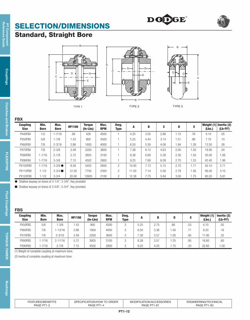
Standard, Straight Bore
TYPE 1
B
E
D D
C
AA
C
D D
E
B
TYPE 2
B
A
DD
E
TYPE 3
FBXCoupling
SizeMin.Bore
Max.Bore HP/100 Torque
(In-Lbs)Max.RPM
Dwg.Type A B C D E Weight (1)
(Lbs.)Inertia (2)(Lb-Ft2)
PX40FBX 1/2 1-7/16 .68 429 4500 1 4.25 3.50 2.88 1.15 .76 4.10 .05
PX50FBX 5/8 1-7/8 1.43 900 4500 1 5.25 4.44 3.14 1.51 .96 7.70 .10
PX60FBX 7/8 2-3/16 2.86 1800 4000 1 6.50 5.59 4.08 1.84 1.28 13.50 .26
PX70FBX 7/8 2-3/8 3.49 2200 3600 1 7.38 6.13 4.63 2.00 1.50 19.90 .54
PX80FBX 1-7/16 2-7/8 5.72 3605 3100 1 8.38 6.69 5.39 2.30 1.50 30.00 1.06
PX90FBX 1-7/16 3-3/8 7.15 4502 2800 1 9.25 7.69 6.09 2.70 1.53 42.40 1.96
PX100FBX 1-7/16 3-3/8 ● 8.58 5402 2600 2 10.00 7.13 5.15 2.70 1.71 50.10 2.71
PX110FBX 1-1/2 3-3/4 ■ 12.30 7750 2300 2 11.00 7.14 5.56 2.79 1.56 56.00 3.10
PX120FBX 1-1/2 3-3/4 20.00 12605 2100 2 12.38 7.75 5.84 3.00 1.75 80.20 5.81
● Shallow keyway on bores of 3-1/4”, 3-3/8”. Key provided.
■ Shallow keyway on bores of 3-5/8”, 3-3/4”. Key provided.
FBSCoupling
SizeMin.Bore
Max.Bore HP/100 Torque
(In-Lbs)Max.RPM
Dwg.Type A B D E Weight (1)
(Lbs.)Inertia (2)(Lb-Ft2)
PX50FBS 5/8 1-3/8 1.43 900 4500 3 5.25 2.75 .88 .53 4.10 .05
PX60FBS 7/8 1-13/16 2.86 1800 4000 3 6.50 3.36 1.00 .71 8.20 .16
PX70FBS 7/8 2-3/16 3.49 2200 3600 3 7.38 3.57 1.00 .95 11.80 .32
PX80FBS 1-7/16 2-11/16 5.72 3605 3100 3 8.38 3.57 1.25 .95 16.60 .60
PX90FBS 1-7/16 2-7/8 7.15 4502 2800 3 9.25 4.03 1.75 .33 22.60 1.00
(1) Weight of complete coupling at maximum bore.
(2) Inertia of complete coupling at maximum bore.
PT1-13
PT
Co
mp
on
en
t R
efe
ren
ce
Gu
ide
Co
up
ling
sC
lutc
hes
an
d B
rake
sF
LE
XID
YN
EF
luid
Co
up
ling
sT
OR
QU
E-T
AM
ER
Bu
shin
gs
SELECTION/DIMENSIONS
FEATURES/BENEFITS PAGE PT1-2
SPECIFICATION/HOW TO ORDER PAGE PT1-4
MODIFICATION/ACCESSORIES PAGE PT1-81
ENGINEERING/TECHNICAL PAGE PT1-83
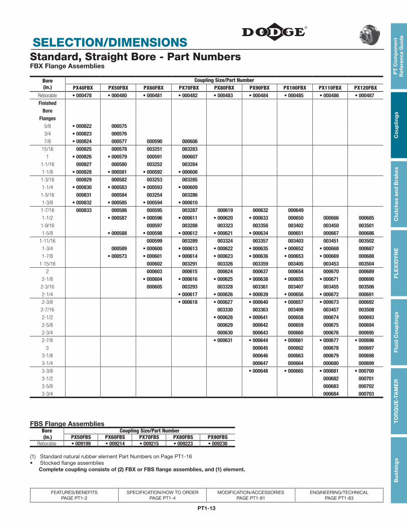
Standard, Straight Bore - Part NumbersFBX Flange Assemblies
Bore(in.)
Coupling Size/Part NumberPX40FBX PX50FBX PX60FBX PX70FBX PX80FBX PX90FBX PX100FBX PX110FBX PX120FBX
Reborable • 000478 • 000480 • 000481 • 000482 • 000483 • 000484 • 000485 • 000486 • 000487Finished
Bore Flanges
5/8 • 000822 0005753/4 • 000823 0005767/8 • 000824 000577 000590 000606
15/16 000825 000578 003251 0032831 • 000826 • 000579 000591 000607
1-1/16 000827 000580 003252 0032841-1/8 • 000828 • 000581 • 000592 • 0006081-3/16 000829 000582 003253 0032851-1/4 • 000830 • 000583 • 000593 • 0006091-5/16 000831 000584 003254 0032861-3/8 • 000832 • 000585 • 000594 • 0006101-7/16 000833 000586 000595 003287 000619 000632 0006491-1/2 • 000587 • 000596 • 000611 • 000620 • 000633 000650 000666 000685
1-9/16 000597 003288 003323 003356 003402 003450 0035011-5/8 • 000588 • 000598 • 000612 • 000621 • 000634 000651 000667 000686
1-11/16 000599 003289 003324 003357 003403 003451 0035021-3/4 000589 • 000600 • 000613 • 000622 • 000635 • 000652 • 000668 0006871-7/8 • 000573 • 000601 • 000614 • 000623 • 000636 • 000653 • 000669 000688
1-15/16 000602 003291 003326 003359 003405 003453 0035042 000603 000615 000624 000637 000654 000670 000689
2-1/8 • 000604 • 000616 • 000625 • 000638 • 000655 • 000671 0006902-3/16 000605 003293 003328 003361 003407 003455 0035062-1/4 • 000617 • 000626 • 000639 • 000656 • 000672 0006912-3/8 • 000618 • 000627 • 000640 • 000657 • 000673 000692
2-7/16 003330 003363 003409 003457 0035082-1/2 • 000628 • 000641 000658 000674 0006932-5/8 000629 000642 000659 000675 0006942-3/4 000630 000643 000660 000676 0006952-7/8 • 000631 • 000644 • 000661 • 000677 • 000696
3 000645 000662 000678 0006973-1/8 000646 000663 000679 0006983-1/4 000647 000664 000680 0006993-3/8 • 000648 • 000665 • 000681 • 0007003-1/2 000682 0007013-5/8 000683 0007023-3/4 000684 000703
FBS Flange AssembliesBore (in.)
Coupling Size/Part NumberPX50FBS PX60FBS PX70FBS PX80FBS PX90FBS
Reborable • 009199 • 009214 • 009215 • 009223 • 009230
(1) Standard natural rubber element Part Numbers on Page PT1-16• Stocked flange assemblies Complete coupling consists of (2) FBX or FBS flange assemblies, and (1) element.
PT1-14
SELECTION/DIMENSIONS
PT
Co
mp
on
en
t R
efe
ren
ce G
uid
eC
ou
plin
gs
Clu
tch
es an
d B
rakesF
LE
XID
YN
EF
luid
Co
up
ling
sT
OR
QU
E-TA
ME
RB
ush
ing
s
FEATURES/BENEFITS PAGE PT1-2
SPECIFICATION/HOW TO ORDER PAGE PT1-4
MODIFICATION/ACCESSORIES PAGE PT1-81
ENGINEERING/TECHNICAL PAGE PT1-83
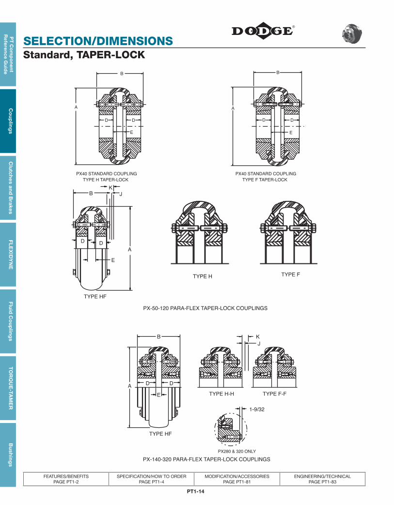
Standard, TAPER-LOCK
D
TYPE H TAPER-LOCK
PX40 STANDARD COUPLING
B
E
D
A
D
TYPE F TAPER-LOCK
PX40 STANDARD COUPLING
B
E
D
A
B
D
E
A
D
K
J
TYPE H TYPE F
TYPE HF
PX-50-120 PARA-FLEX TAPER-LOCK COUPLINGS
A
E
D
B K
J
TYPE H-H TYPE F-F
TYPE HF
1-9/32
PX280 & 320 ONLY
D
PX-140-320 PARA-FLEX TAPER-LOCK COUPLINGS
PT1-15
PT
Co
mp
on
en
t R
efe
ren
ce
Gu
ide
Co
up
ling
sC
lutc
hes
an
d B
rake
sF
LE
XID
YN
EF
luid
Co
up
ling
sT
OR
QU
E-T
AM
ER
Bu
shin
gs
SELECTION/DIMENSIONS
FEATURES/BENEFITS PAGE PT1-2
SPECIFICATION/HOW TO ORDER PAGE PT1-4
MODIFICATION/ACCESSORIES PAGE PT1-81
ENGINEERING/TECHNICAL PAGE PT1-83
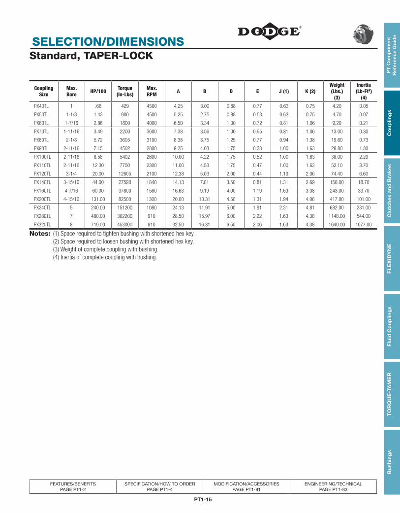
Standard, TAPER-LOCK
CouplingSize
Max.Bore HP/100 Torque
(In-Lbs)Max.RPM A B D E J (1) K (2)
Weight(Lbs.)
(3)
Inertia(Lb-Ft2)
(4)
PX40TL 1 .68 429 4500 4.25 3.00 0.88 0.77 0.63 0.75 4.20 0.05
PX50TL 1-1/8 1.43 900 4500 5.25 2.75 0.88 0.53 0.63 0.75 4.70 0.07
PX60TL 1-7/16 2.86 1800 4000 6.50 3.34 1.00 0.72 0.81 1.06 9.20 0.21
PX70TL 1-11/16 3.49 2200 3600 7.38 3.56 1.00 0.95 0.81 1.06 13.00 0.30
PX80TL 2-1/8 5.72 3605 3100 8.38 3.75 1.25 0.77 0.94 1.38 19.60 0.73
PX90TL 2-11/16 7.15 4502 2800 9.25 4.03 1.75 0.33 1.00 1.63 28.80 1.30
PX100TL 2-11/16 8.58 5402 2600 10.00 4.22 1.75 0.52 1.00 1.63 38.00 2.20
PX110TL 2-11/16 12.30 7750 2300 11.00 4.53 1.75 0.47 1.00 1.63 52.10 3.70
PX120TL 3-1/4 20.00 12605 2100 12.38 5.03 2.00 0.44 1.19 2.06 74.40 6.60
PX140TL 3-15/16 44.00 27590 1840 14.13 7.81 3.50 0.81 1.31 2.69 156.00 18.70
PX160TL 4-7/16 60.00 37800 1560 16.63 9.19 4.00 1.19 1.63 3.38 243.00 33.70
PX200TL 4-15/16 131.00 82500 1300 20.00 10.31 4.50 1.31 1.94 4.06 417.00 101.00
PX240TL 5 240.00 151200 1080 24.13 11.91 5.00 1.91 2.31 4.81 682.00 231.00
PX280TL 7 480.00 302200 910 28.50 15.97 6.00 2.22 1.63 4.38 1148.00 544.00
PX320TL 8 719.00 453000 810 32.50 16.31 6.50 2.06 1.63 4.38 1640.00 1077.00
Notes: (1) Space required to tighten bushing with shortened hex key. (2) Space required to loosen bushing with shortened hex key. (3) Weight of complete coupling with bushing. (4) Inertia of complete coupling with bushing.
PT1-16
SELECTION/DIMENSIONS
PT
Co
mp
on
en
t R
efe
ren
ce G
uid
eC
ou
plin
gs
Clu
tch
es an
d B
rakesF
LE
XID
YN
EF
luid
Co
up
ling
sT
OR
QU
E-TA
ME
RB
ush
ing
s
FEATURES/BENEFITS PAGE PT1-2
SPECIFICATION/HOW TO ORDER PAGE PT1-4
MODIFICATION/ACCESSORIES PAGE PT1-81
ENGINEERING/TECHNICAL PAGE PT1-83
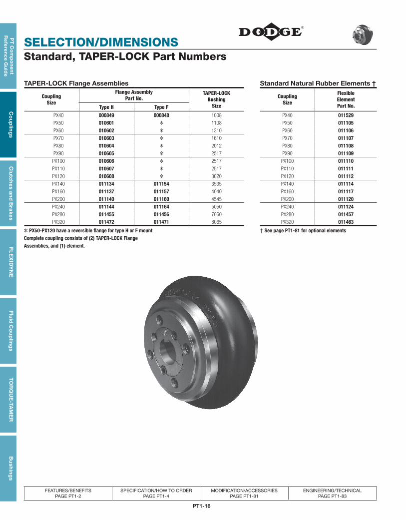
Standard, TAPER-LOCK Part Numbers
TAPER-LOCK Flange Assemblies Standard Natural Rubber Elements †
CouplingSize
Flange AssemblyPart No.
TAPER-LOCKBushing
Size
Coupling Size
FlexibleElementPart No.Type H Type F
PX40 000849 000848 1008 PX40 011529PX50 010601 ✻ 1108 PX50 011105PX60 010602 ✻ 1310 PX60 011106PX70 010603 ✻ 1610 PX70 011107PX80 010604 ✻ 2012 PX80 011108PX90 010605 ✻ 2517 PX90 011109
PX100 010606 ✻ 2517 PX100 011110PX110 010607 ✻ 2517 PX110 011111PX120 010608 ✻ 3020 PX120 011112PX140 011134 011154 3535 PX140 011114PX160 011137 011157 4040 PX160 011117PX200 011140 011160 4545 PX200 011120PX240 011144 011164 5050 PX240 011124PX280 011455 011456 7060 PX280 011457PX320 011472 011471 8065 PX320 011463
✽ PX50-PX120 have a reversible flange for type H or F mount † See page PT1-81 for optional elementsComplete coupling consists of (2) TAPER-LOCK FlangeAssemblies, and (1) element.
PT1-17
PT
Co
mp
on
en
t R
efe
ren
ce
Gu
ide
Co
up
ling
sC
lutc
hes
an
d B
rake
sF
LE
XID
YN
EF
luid
Co
up
ling
sT
OR
QU
E-T
AM
ER
Bu
shin
gs
SELECTION/DIMENSIONS
FEATURES/BENEFITS PAGE PT1-2
SPECIFICATION/HOW TO ORDER PAGE PT1-4
MODIFICATION/ACCESSORIES PAGE PT1-81
ENGINEERING/TECHNICAL PAGE PT1-83
Standard, TAPER-LOCK Part Numbers
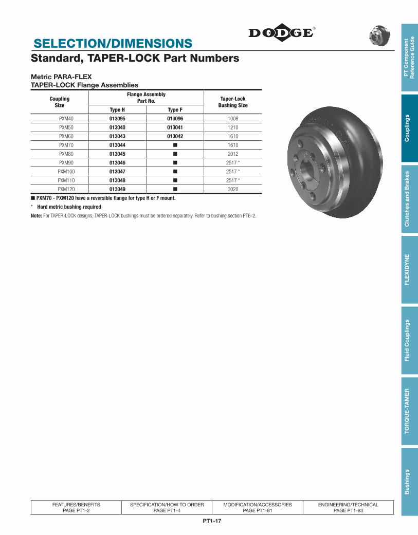
Metric PARA-FLEXTAPER-LOCK Flange Assemblies
Coupling Size
Flange AssemblyPart No. Taper-Lock
Bushing SizeType H Type F
PXM40 013095 013096 1008
PXM50 013040 013041 1210
PXM60 013043 013042 1610
PXM70 013044 ■ 1610
PXM80 013045 ■ 2012
PXM90 013046 ■ 2517 *
PXM100 013047 ■ 2517 *
PXM110 013048 ■ 2517 *
PXM120 013049 ■ 3020
■ PXM70 - PXM120 have a reversible flange for type H or F mount.
* Hard metric bushing required
Note: For TAPER-LOCK designs, TAPER-LOCK bushings must be ordered separately. Refer to bushing section PT6-2.
PT1-18
SELECTION/DIMENSIONS
PT
Co
mp
on
en
t R
efe
ren
ce G
uid
eC
ou
plin
gs
Clu
tch
es an
d B
rakesF
LE
XID
YN
EF
luid
Co
up
ling
sT
OR
QU
E-TA
ME
RB
ush
ing
s
FEATURES/BENEFITS PAGE PT1-2
SPECIFICATION/HOW TO ORDER PAGE PT1-4
MODIFICATION/ACCESSORIES PAGE PT1-81
ENGINEERING/TECHNICAL PAGE PT1-83
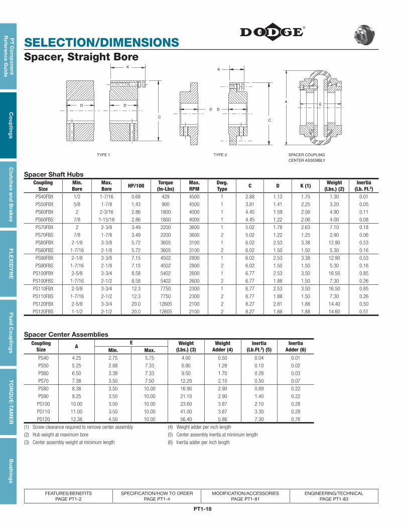
Spacer, Straight Bore
TYPE 1
C
D
K
D
TYPE 2
D
C
K
D
EA
CENTER ASSEMBLY
SPACER COUPLING
Spacer Shaft HubsCoupling
SizeMin.Bore
Max.Bore HP/100 Torque
(In-Lbs)Max.RPM
Dwg.Type C D K (1) Weight
(Lbs.) (2)Inertia
(Lb. Ft.2)PS40FBX 1/2 1-7/16 0.68 429 4500 1 2.88 1.13 1.75 1.30 0.01
PS50FBX 5/8 1-7/8 1.43 900 4500 1 3.81 1.41 2.25 3.20 0.05
PS60FBX 2 2-3/16 2.86 1800 4000 1 4.45 1.59 2.56 4.90 0.11
PS60FBS 7/8 1-15/16 2.86 1800 4000 1 4.45 1.22 2.06 4.00 0.08
PS70FBX 2 2-3/8 3.49 2200 3600 1 5.02 1.78 2.63 7.10 0.18
PS70FBS 7/8 1-7/8 3.49 2200 3600 2 5.02 1.22 1.25 2.90 0.06
PS80FBX 2-1/8 3-3/8 5.72 3605 3100 1 6.02 2.53 3.38 12.90 0.53
PS80FBS 1-7/16 2-1/8 5.72 3605 3100 2 6.02 1.50 1.50 5.30 0.16
PS90FBX 2-1/8 3-3/8 7.15 4502 2800 1 6.02 2.53 3.38 12.90 0.53
PS90FBS 1-7/16 2-1/8 7.15 4502 2800 2 6.02 1.50 1.50 5.30 0.16
PS100FBX 2-5/8 3-3/4 8.58 5402 2600 1 6.77 2.53 3.50 16.50 0.85
PS100FBS 1-7/16 2-1/2 8.58 5402 2600 2 6.77 1.88 1.50 7.30 0.26
PS110FBX 2-5/8 3-3/4 12.3 7750 2300 1 6.77 2.53 3.50 16.50 0.85
PS110FBS 1-7/16 2-1/2 12.3 7750 2300 2 6.77 1.88 1.50 7.30 0.26
PS120FBX 2-5/8 3-3/4 20.0 12605 2100 2 8.27 2.81 1.88 14.40 0.50
PS120FBS 1-1/2 2-1/2 20.0 12605 2100 2 8.27 1.88 1.88 14.60 0.51
Spacer Center AssembliesCoupling
Size AE Weight
(Lbs.) (3)Weight
Adder (4)Inertia
(Lb.Ft.2) (5)Inertia
Adder (6)Min. Max.PS40 4.25 2.75 5.75 4.00 0.50 0.04 0.01
PS50 5.25 2.88 7.33 6.90 1.28 0.10 0.02
PS60 6.50 3.38 7.33 9.50 1.70 0.28 0.03
PS70 7.38 3.50 7.50 12.20 2.10 0.50 0.07
PS80 8.38 3.50 10.00 16.90 2.90 0.89 0.22
PS90 9.25 3.50 10.00 21.10 2.90 1.40 0.22
PS100 10.00 3.50 10.00 23.60 3.87 2.10 0.28
PS110 11.00 3.50 10.00 41.00 3.87 3.30 0.28
PS120 12.38 4.50 10.00 56.40 5.86 7.30 0.76
(1) Screw clearance required to remove center assembly (4) Weight adder per inch length
(2) Hub weight at maximum bore (5) Center assembly inertia at minimum length
(3) Center assembly weight at minimum length (6) Inertia adder per inch length
PT1-19
PT
Co
mp
on
en
t R
efe
ren
ce
Gu
ide
Co
up
ling
sC
lutc
hes
an
d B
rake
sF
LE
XID
YN
EF
luid
Co
up
ling
sT
OR
QU
E-T
AM
ER
Bu
shin
gs
SELECTION/DIMENSIONS
FEATURES/BENEFITS PAGE PT1-2
SPECIFICATION/HOW TO ORDER PAGE PT1-4
MODIFICATION/ACCESSORIES PAGE PT1-81
ENGINEERING/TECHNICAL PAGE PT1-83
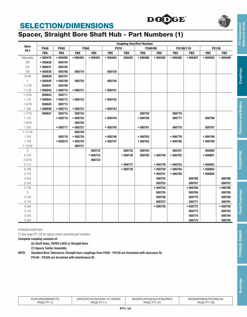
Spacer, Straight Bore Shaft Hub - Part Numbers (1)
Bore(in.)
Coupling Size/Part NumberPS40 PS50 PS60 PS70 PS80/90 PS100/110 PS120FBX FBX FBS FBX FBS FBX FBS FBX FBS FBX FBS FBX
Reborable • 000479 • 000490 • 000492 • 000491 • 000494 000493 • 000496 • 000495 • 000498 • 000497 • 000500 • 0004995/8 • 000836 0007043/4 • 000837 0007057/8 • 000838 000706 000719 000739
15/16 000839 0007071 • 000840 • 000708 000720 000740
1-1/16 000841 0007091-1/8 • 000842 • 000710 • 000721 • 0007411-3/16 000843 0007111-1/4 • 000844 • 000712 • 000722 • 0007421-5/16 000845 0007131-3/8 • 000846 • 000714 • 000723 • 0007431-7/16 000847 000715 000724 000759 0007761-1/2 • 000716 • 000725 • 000744 • 000760 000777 000796
1-9/16 0007261-5/8 • 000717 • 000727 • 000745 • 000761 000778 000797
1-11/16 0007281-3/4 000718 • 000729 • 000746 • 000762 • 000779 • 0007981-7/8 • 000574 • 000730 • 000747 • 000763 • 000780 • 000799
1-15/16 0007312 000732 000735 000764 000781 000800
2-1/8 • 000733 • 000736 000765 • 000748 • 000782 • 000801 2-3/16 0007342-1/4 • 000737 • 000749 • 000783 • 0008022-3/8 • 000738 • 000750 • 000784 • 0008032-1/2 • 000751 • 000785 • 0008042-5/8 000752 000766 0007862-3/4 000753 000767 0007872-7/8 • 000754 • 000768 • 000788
3 000755 000769 0007893-1/8 000756 000770 0007903-1/4 000757 000771 0007913-3/8 • 000758 • 000772 • 0007923-1/2 000773 0007933-5/8 000774 0007943-3/4 000775 000795
• Stocked shaft hubs
(1) See page PT1-22 for spacer center assembly part numbers.
Complete coupling consists of: (2) Shaft Hubs, TAPER-LOCK or Straight Bore (1) Spacer Center AssemblyNOTE: Standard Bore Tolerances: Straight bore couplings from PX40 - PX120 are furnished with clearance fit. PX140 - PX320 are furnished with interference fit.
PT1-20
SELECTION/DIMENSIONS
PT
Co
mp
on
en
t R
efe
ren
ce G
uid
eC
ou
plin
gs
Clu
tch
es an
d B
rakesF
LE
XID
YN
EF
luid
Co
up
ling
sT
OR
QU
E-TA
ME
RB
ush
ing
s
FEATURES/BENEFITS PAGE PT1-2
SPECIFICATION/HOW TO ORDER PAGE PT1-4
MODIFICATION/ACCESSORIES PAGE PT1-81
ENGINEERING/TECHNICAL PAGE PT1-83
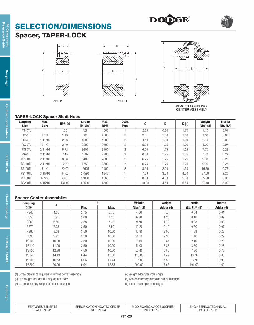
Spacer, TAPER-LOCK
TYPE 1 TYPE 2
C
C
KK
DDE
A
CENTER ASSEMBLY
SPACER COUPLING
TAPER-LOCK Spacer Shaft HubsCoupling
SizeMax.Bore HP/100 Torque
(In-Lbs)Max.RPM
Dwg.Type C D K (1) Weight
(Lbs) (2)Inertia
(Lb. Ft.²)PS40TL 1 .68 429 4500 1 2.88 0.88 1.75 1.10 0.01
PS50TL 1-1/4 1.43 900 4500 2 3.81 1.00 1.00 1.80 0.02
PS60TL 1-11/16 2.86 1800 4000 2 4.44 1.00 1.00 2.40 0.03
PS70TL 2-1/8 3.49 2200 3600 2 5.00 1.25 1.00 4.00 0.07
PS80TL 2-11/16 5.72 3605 3100 2 6.00 1.75 1.25 7.70 0.22
PS90TL 2-11/16 7.15 4502 2800 2 6.00 1.75 1.25 7.70 0.22
PS100TL 2-11/16 8.58 5402 2600 2 6.75 1.75 1.25 9.00 0.28
PS110TL 2-11/16 12.30 7750 2300 2 6.75 1.75 1.25 9.00 0.28
PS120TL 3-1/4 20.00 12605 2100 2 8.25 2.00 1.50 16.60 0.76
PS140TL 3-15/16 44.00 27590 1840 1 7.69 3.50 4.50 37.00 2.20
PS160TL 4-7/16 60.00 37800 1560 1 8.63 4.00 5.00 55.00 3.90
PS200TL 4-15/16 131.00 82500 1300 1 10.00 4.50 5.50 87.40 8.00
Spacer Center AssembliesCoupling
Size AE Weight Weight Inertia Inertia
Min. Max. (Lbs.) (3) Adder (4) (Lb. Ft.2) (5) Adder (6)PS40 4.25 2.75 5.75 4.00 .50 0.04 0.01
PS50 5.25 2.88 7.33 6.90 1.28 0.10 0.02
PS60 6.50 3.38 7.33 9.50 1.70 0.28 0.03
PS70 7.38 3.50 7.50 12.20 2.10 0.50 0.07
PS80 8.38 3.50 10.00 16.90 2.90 1.89 0.22
PS90 9.25 3.50 10.00 21.10 2.90 1.40 0.22
PS100 10.00 3.50 10.00 23.60 3.87 2.10 0.28
PS110 11.00 3.50 10.00 41.00 3.87 3.30 0.28
PS120 12.38 4.50 10.00 56.40 5.86 7.30 0.76
PS140 14.13 6.44 13.00 115.00 4.49 18.70 0.80
PS160 16.63 8.06 11.44 216.00 5.58 33.70 0.90
PS200 20.00 9.94 12.88 290.00 7.65 101.00 1.60
(1) Screw clearance required to remove center assembly (4) Weight adder per inch length
(2) Hub weight includes bushing at max. bore (5) Center assembly inertia at minimum length
(3) Center assembly weight at minimum length (6) Inertia added per inch length
PT1-21
PT
Co
mp
on
en
t R
efe
ren
ce
Gu
ide
Co
up
ling
sC
lutc
hes
an
d B
rake
sF
LE
XID
YN
EF
luid
Co
up
ling
sT
OR
QU
E-T
AM
ER
Bu
shin
gs
SELECTION/DIMENSIONS
FEATURES/BENEFITS PAGE PT1-2
SPECIFICATION/HOW TO ORDER PAGE PT1-4
MODIFICATION/ACCESSORIES PAGE PT1-81
ENGINEERING/TECHNICAL PAGE PT1-83
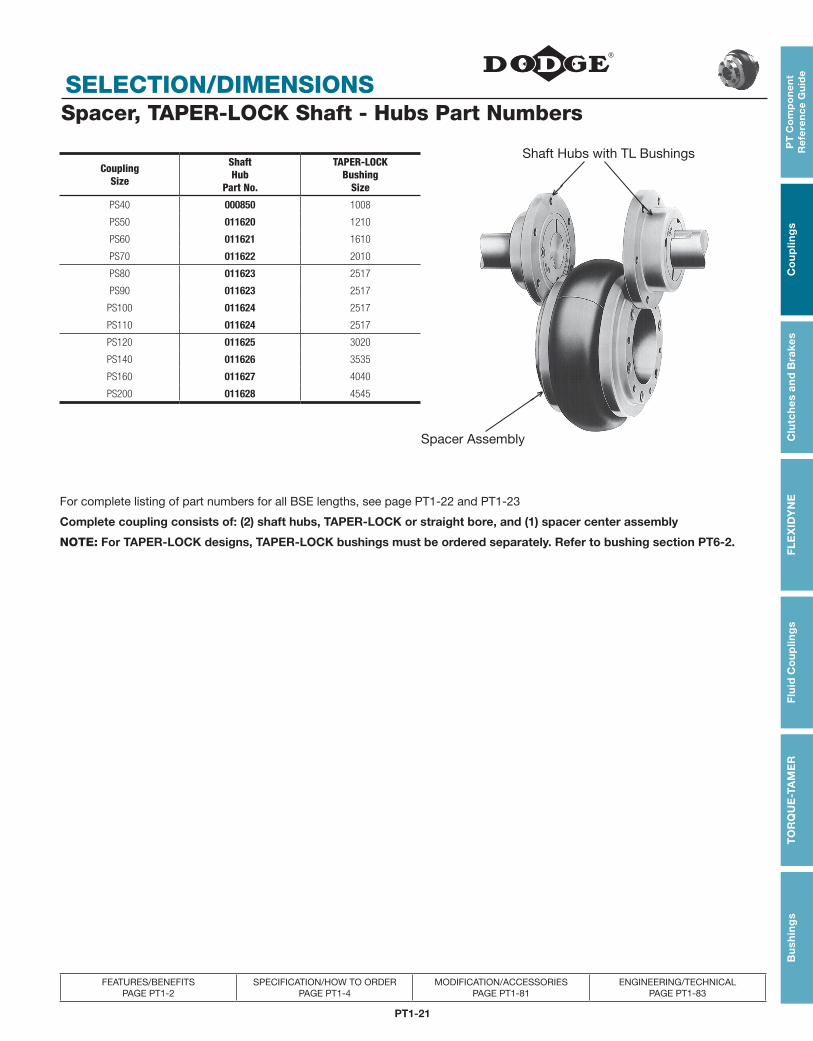
Spacer, TAPER-LOCK Shaft - Hubs Part Numbers
CouplingSize
ShaftHub
Part No.
TAPER-LOCKBushing
Size
PS40 000850 1008
PS50 011620 1210
PS60 011621 1610
PS70 011622 2010
PS80 011623 2517
PS90 011623 2517
PS100 011624 2517
PS110 011624 2517
PS120 011625 3020
PS140 011626 3535
PS160 011627 4040
PS200 011628 4545
For complete listing of part numbers for all BSE lengths, see page PT1-22 and PT1-23
Complete coupling consists of: (2) shaft hubs, TAPER-LOCK or straight bore, and (1) spacer center assembly
NOTE: For TAPER-LOCK designs, TAPER-LOCK bushings must be ordered separately. Refer to bushing section PT6-2.
Shaft Hubs with TL Bushings
Spacer Assembly
↑↑
↑
PT1-22
SELECTION/DIMENSIONS
PT
Co
mp
on
en
t R
efe
ren
ce G
uid
eC
ou
plin
gs
Clu
tch
es an
d B
rakesF
LE
XID
YN
EF
luid
Co
up
ling
sT
OR
QU
E-TA
ME
RB
ush
ing
s
FEATURES/BENEFITS PAGE PT1-2
SPECIFICATION/HOW TO ORDER PAGE PT1-4
MODIFICATION/ACCESSORIES PAGE PT1-81
ENGINEERING/TECHNICAL PAGE PT1-83
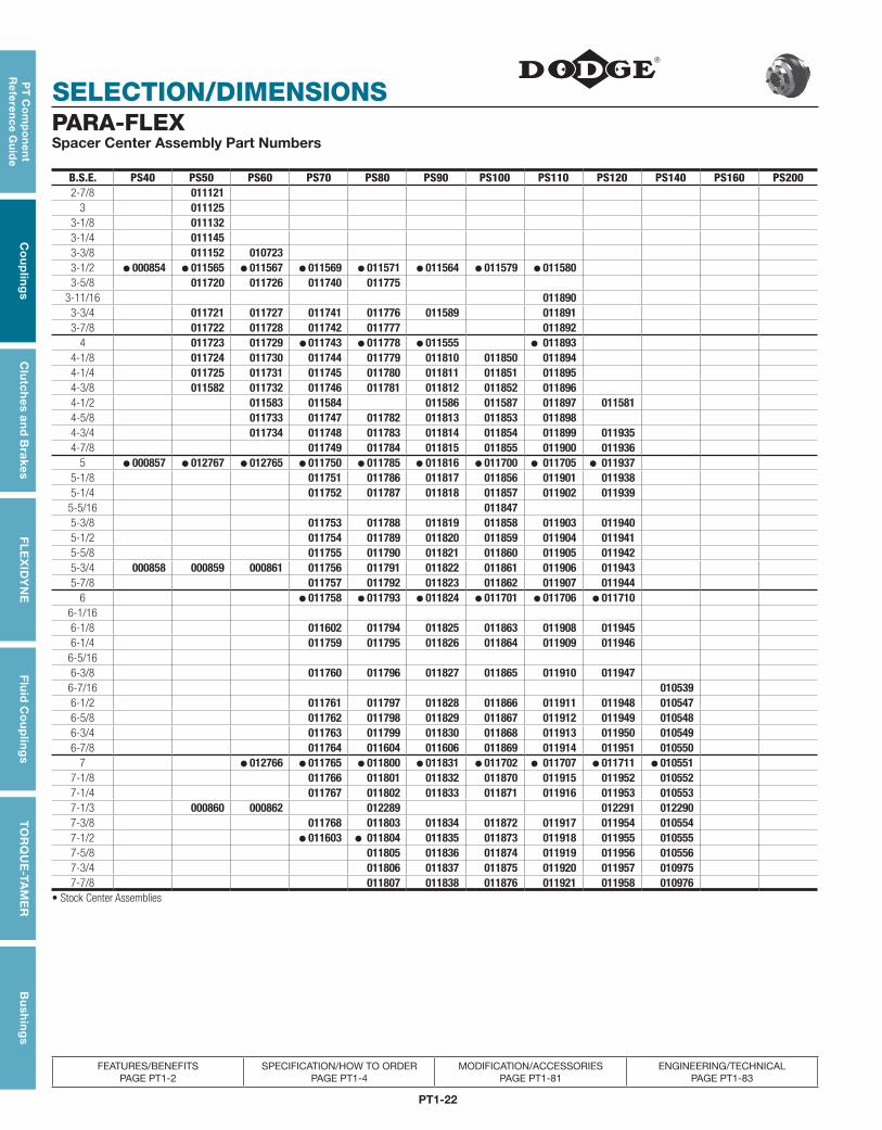
PARA-FLEXSpacer Center Assembly Part Numbers
B.S.E. PS40 PS50 PS60 PS70 PS80 PS90 PS100 PS110 PS120 PS140 PS160 PS2002-7/8 011121
3 0111253-1/8 0111323-1/4 0111453-3/8 011152 0107233-1/2 ● 000854 ● 011565 ● 011567 ● 011569 ● 011571 ● 011564 ● 011579 ● 0115803-5/8 011720 011726 011740 011775
3-11/16 0118903-3/4 011721 011727 011741 011776 011589 0118913-7/8 011722 011728 011742 011777 011892
4 011723 011729 ● 011743 ● 011778 ● 011555 ● 0118934-1/8 011724 011730 011744 011779 011810 011850 0118944-1/4 011725 011731 011745 011780 011811 011851 0118954-3/8 011582 011732 011746 011781 011812 011852 0118964-1/2 011583 011584 011586 011587 011897 0115814-5/8 011733 011747 011782 011813 011853 0118984-3/4 011734 011748 011783 011814 011854 011899 0119354-7/8 011749 011784 011815 011855 011900 011936
5 ● 000857 ● 012767 ● 012765 ● 011750 ● 011785 ● 011816 ● 011700 ● 011705 ● 0119375-1/8 011751 011786 011817 011856 011901 0119385-1/4 011752 011787 011818 011857 011902 0119395-5/16 0118475-3/8 011753 011788 011819 011858 011903 0119405-1/2 011754 011789 011820 011859 011904 0119415-5/8 011755 011790 011821 011860 011905 0119425-3/4 000858 000859 000861 011756 011791 011822 011861 011906 0119435-7/8 011757 011792 011823 011862 011907 011944
6 ● 011758 ● 011793 ● 011824 ● 011701 ● 011706 ● 0117106-1/166-1/8 011602 011794 011825 011863 011908 0119456-1/4 011759 011795 011826 011864 011909 0119466-5/166-3/8 011760 011796 011827 011865 011910 0119476-7/16 0105396-1/2 011761 011797 011828 011866 011911 011948 0105476-5/8 011762 011798 011829 011867 011912 011949 0105486-3/4 011763 011799 011830 011868 011913 011950 0105496-7/8 011764 011604 011606 011869 011914 011951 010550
7 ● 012766 ● 011765 ● 011800 ● 011831 ● 011702 ● 011707 ● 011711 ● 0105517-1/8 011766 011801 011832 011870 011915 011952 0105527-1/4 011767 011802 011833 011871 011916 011953 0105537-1/3 000860 000862 012289 012291 0122907-3/8 011768 011803 011834 011872 011917 011954 0105547-1/2 ● 011603 ● 011804 011835 011873 011918 011955 0105557-5/8 011805 011836 011874 011919 011956 0105567-3/4 011806 011837 011875 011920 011957 0109757-7/8 011807 011838 011876 011921 011958 010976
• Stock Center Assemblies
PT1-23
PT
Co
mp
on
en
t R
efe
ren
ce
Gu
ide
Co
up
ling
sC
lutc
hes
an
d B
rake
sF
LE
XID
YN
EF
luid
Co
up
ling
sT
OR
QU
E-T
AM
ER
Bu
shin
gs
SELECTION/DIMENSIONS
FEATURES/BENEFITS PAGE PT1-2
SPECIFICATION/HOW TO ORDER PAGE PT1-4
MODIFICATION/ACCESSORIES PAGE PT1-81
ENGINEERING/TECHNICAL PAGE PT1-83
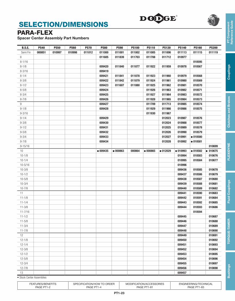
B.S.E. PS40 PS50 PS60 PS70 PS80 PS90 PS100 PS110 PS120 PS140 PS160 PS200
Semi Fin 000851 010997 010998 011012 011000 011001 011002 011005 011006 011113 011115 011119
8 011605 011839 011703 011708 011712 010977
8-1/16 010595
8-1/8 009420 011840 011877 011922 011959 010978 010567
8-3/16 009419
8-1/4 009421 011841 011878 011923 011960 010979 010568
8-3/8 009422 011842 011879 011924 011961 010980 010569
8-1/2 009423 011607 011880 011925 011962 010981 010570
8-5/8 009424 011926 011963 010982 010571
8-3/4 009425 011927 011964 010983 010572
8-7/8 009426 011928 011965 010984 010573
9 009427 011709 011713 010985 010574
9-1/8 009428 011929 011966 010986 010575
9-3/16 011930 011967
9-1/4 009429 012023 010987 010576
9-3/8 009430 012024 010988 010577
9-1/2 009431 012025 010989 010578
9-5/8 009432 012026 010990 010579
9-3/4 009433 012027 010991 ● 010580
9-7/8 009434 012028 010992 ● 010581
9-15/16 010699
10 ● 009435 ● 000863 000864 ● 000865 ● 012029 ● 010993 ● 010582 ● 010675
10-1/8 010994 010583 010676
10-1/4 010995 010584 010677
10-5/16 010996
10-3/8 009436 010585 010678
10-1/2 009437 010586 010679
10-5/8 009438 010587 010680
10-3/4 009439 010588 010681
10-7/8 009440 010589 010682
11 009441 010590 010683
11-1/8 009442 010591 010684
11-1/4 009443 010592 010685
11-3/8 009444 010593 010686
11-7/16 010594
11-1/2 009445 010687
11-5/8 009446 010688
11-3/4 009447 010689
11-7/8 009448 010690
12 009449 010691
12-1/8 009450 010692
12-1/4 009451 010693
12-3/8 009452 010694
12-1/2 009453 010695
12-5/8 009454 010696
12-3/4 009455 010697
12-7/8 009456 010698
13 009457
• Stock Center Assemblies
PARA-FLEXSpacer Center Assembly Part Numbers
PT1-24
SELECTION/DIMENSIONS
PT
Co
mp
on
en
t R
efe
ren
ce G
uid
eC
ou
plin
gs
Clu
tch
es an
d B
rakesF
LE
XID
YN
EF
luid
Co
up
ling
sT
OR
QU
E-TA
ME
RB
ush
ing
s
FEATURES/BENEFITS PAGE PT1-2
SPECIFICATION/HOW TO ORDER PAGE PT1-4
MODIFICATION/ACCESSORIES PAGE PT1-81
ENGINEERING/TECHNICAL PAGE PT1-83
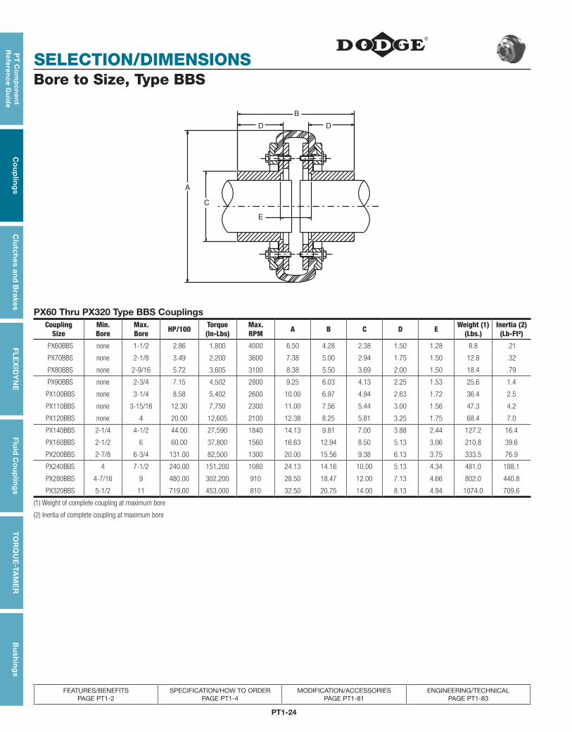
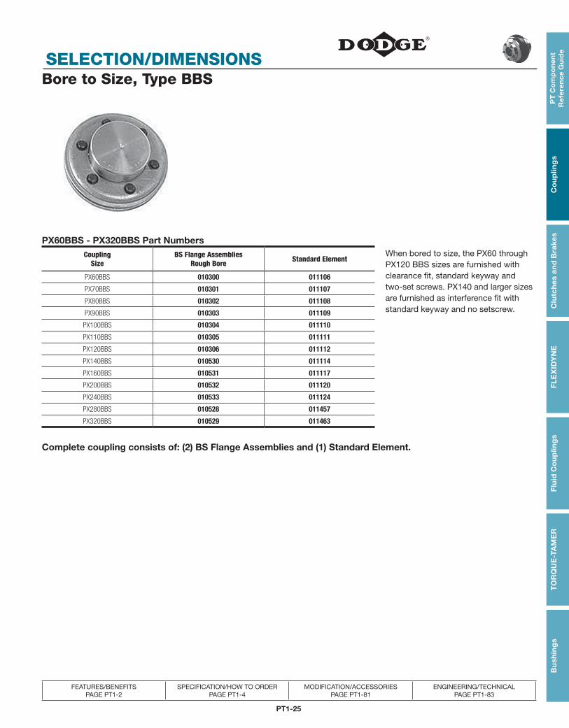
Bore to Size, Type BBS
E
C
A
D D
B
PX60 Thru PX320 Type BBS CouplingsCoupling
SizeMin.Bore
Max.Bore HP/100 Torque
(In-Lbs)Max.RPM A B C D E Weight (1)
(Lbs.)Inertia (2)(Lb-Ft²)
PX60BBS none 1-1/2 2.86 1,800 4000 6.50 4.28 2.38 1.50 1.28 8.8 .21
PX70BBS none 2-1/8 3.49 2,200 3600 7.38 5.00 2.94 1.75 1.50 12.8 .32
PX80BBS none 2-9/16 5.72 3,605 3100 8.38 5.50 3.69 2.00 1.50 18.4 .79
PX90BBS none 2-3/4 7.15 4,502 2800 9.25 6.03 4.13 2.25 1.53 25.6 1.4
PX100BBS none 3-1/4 8.58 5,402 2600 10.00 6.97 4.94 2.63 1.72 36.4 2.5
PX110BBS none 3-15/16 12.30 7,750 2300 11.00 7.56 5.44 3.00 1.56 47.3 4.2
PX120BBS none 4 20.00 12,605 2100 12.38 8.25 5.81 3.25 1.75 68.4 7.0
PX140BBS 2-1/4 4-1/2 44.00 27,590 1840 14.13 9.81 7.00 3.88 2.44 127.2 16.4
PX160BBS 2-1/2 6 60.00 37,800 1560 16.63 12.94 8.50 5.13 3.06 210.8 39.6
PX200BBS 2-7/8 6-3/4 131.00 82,500 1300 20.00 15.56 9.38 6.13 3.75 333.5 76.9
PX240BBS 4 7-1/2 240.00 151,200 1080 24.13 14.16 10.00 5.13 4.34 481.0 188.1
PX280BBS 4-7/16 9 480.00 302,200 910 28.50 18.47 12.00 7.13 4.66 802.0 440.8
PX320BBS 5-1/2 11 719.00 453,000 810 32.50 20.75 14.00 8.13 4.94 1074.0 709.6
(1) Weight of complete coupling at maximum bore
(2) Inertia of complete coupling at maximum bore
PT1-25
PT
Co
mp
on
en
t R
efe
ren
ce
Gu
ide
Co
up
ling
sC
lutc
hes
an
d B
rake
sF
LE
XID
YN
EF
luid
Co
up
ling
sT
OR
QU
E-T
AM
ER
Bu
shin
gs
SELECTION/DIMENSIONS
FEATURES/BENEFITS PAGE PT1-2
SPECIFICATION/HOW TO ORDER PAGE PT1-4
MODIFICATION/ACCESSORIES PAGE PT1-81
ENGINEERING/TECHNICAL PAGE PT1-83
Bore to Size, Type BBS
PX60BBS - PX320BBS Part NumbersCoupling
SizeBS Flange Assemblies
Rough Bore Standard ElementWhen bored to size, the PX60 through PX120 BBS sizes are furnished with clearance fit, standard keyway and two-set screws. PX140 and larger sizes are furnished as interference fit with standard keyway and no setscrew.
PX60BBS 010300 011106
PX70BBS 010301 011107
PX80BBS 010302 011108
PX90BBS 010303 011109
PX100BBS 010304 011110
PX110BBS 010305 011111
PX120BBS 010306 011112
PX140BBS 010530 011114
PX160BBS 010531 011117
PX200BBS 010532 011120
PX240BBS 010533 011124
PX280BBS 010528 011457
PX320BBS 010529 011463
Complete coupling consists of: (2) BS Flange Assemblies and (1) Standard Element.
PT1-26
SELECTION/DIMENSIONS
PT
Co
mp
on
en
t R
efe
ren
ce G
uid
eC
ou
plin
gs
Clu
tch
es an
d B
rakesF
LE
XID
YN
EF
luid
Co
up
ling
sT
OR
QU
E-TA
ME
RB
ush
ing
s
FEATURES/BENEFITS PAGE PT1-2
SPECIFICATION/HOW TO ORDER PAGE PT1-4
MODIFICATION/ACCESSORIES PAGE PT1-81
ENGINEERING/TECHNICAL PAGE PT1-83
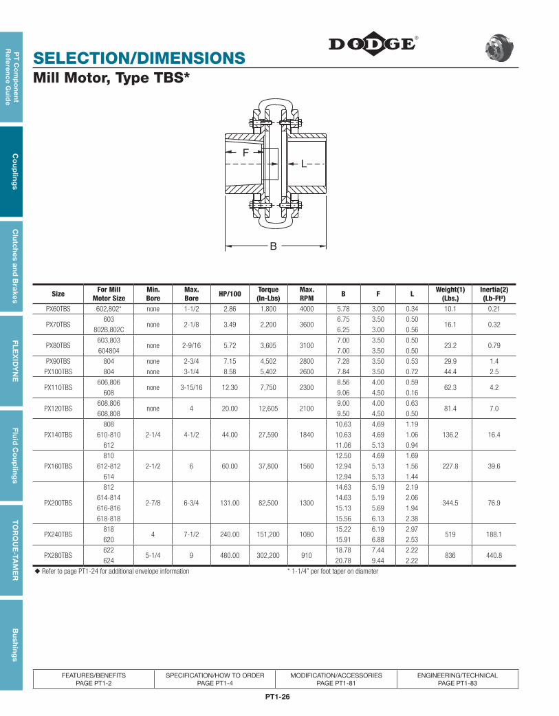
Mill Motor, Type TBS*
L
F
B
Size For MillMotor Size
Min.Bore
Max.Bore HP/100 Torque
(In-Lbs)Max.RPM B F L Weight(1)
(Lbs.)Inertia(2)(Lb-Ft²)
PX60TBS 602,802* none 1-1/2 2.86 1,800 4000 5.78 3.00 0.34 10.1 0.21
PX70TBS603
none 2-1/8 3.49 2,200 36006.75 3.50 0.50
16.1 0.32802B,802C 6.25 3.00 0.56
PX80TBS603,803
none 2-9/16 5.72 3,605 31007.00 3.50 0.50
23.2 0.79604804 7.00 3.50 0.50
PX90TBS 804 none 2-3/4 7.15 4,502 2800 7.28 3.50 0.53 29.9 1.4
PX100TBS 804 none 3-1/4 8.58 5,402 2600 7.84 3.50 0.72 44.4 2.5
PX110TBS606,806
none 3-15/16 12.30 7,750 23008.56 4.00 0.59
62.3 4.2608 9.06 4.50 0.16
PX120TBS608,806
none 4 20.00 12,605 21009.00 4.00 0.63
81.4 7.0608,808 9.50 4.50 0.50
PX140TBS
808
2-1/4 4-1/2 44.00 27,590 1840
10.63 4.69 1.19
136.2 16.4610-810 10.63 4.69 1.06
612 11.06 5.13 0.94
PX160TBS
810
2-1/2 6 60.00 37,800 1560
12.50 4.69 1.69
227.8 39.6612-812 12.94 5.13 1.56
614 12.94 5.13 1.44
PX200TBS
812
2-7/8 6-3/4 131.00 82,500 1300
14.63 5.19 2.19
344.5 76.9614-814 14.63 5.19 2.06
616-816 15.13 5.69 1.94
618-818 15.56 6.13 2.38
PX240TBS818
4 7-1/2 240.00 151,200 108015.22 6.19 2.97
519 188.1620 15.91 6.88 2.53
PX280TBS622
5-1/4 9 480.00 302,200 91018.78 7.44 2.22
836 440.8624 20.78 9.44 2.22
◆ Refer to page PT1-24 for additional envelope information * 1-1/4” per foot taper on diameter
PT1-27
PT
Co
mp
on
en
t R
efe
ren
ce
Gu
ide
Co
up
ling
sC
lutc
hes
an
d B
rake
sF
LE
XID
YN
EF
luid
Co
up
ling
sT
OR
QU
E-T
AM
ER
Bu
shin
gs
SELECTION/DIMENSIONS
FEATURES/BENEFITS PAGE PT1-2
SPECIFICATION/HOW TO ORDER PAGE PT1-4
MODIFICATION/ACCESSORIES PAGE PT1-81
ENGINEERING/TECHNICAL PAGE PT1-83
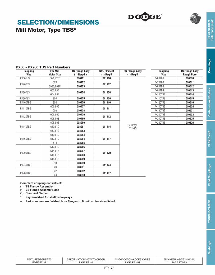
Mill Motor, Type TBS*
PX60 - PX280 TBS Part NumbersCoupling
SizeFor Mill
Motor SizeTS Flange Assy
(1) Req’d +Std. Element
(1) Req’dBS Flange Assy
(1) Req’dCoupling
SizeTS Flange Assy
Rough BorePX60TBS 602,802* 010471 011106
See Page PT1-25
PX60TBS 010510
PX70TBS603 010472
011107PX70TBS 010511
802B,802C 010473 PX80TBS 010512
PX80TBS603,803
010474 011108PX90TBS 010513
604,804 PX100TBS 010514PX90TBS 804 010475 011109 PX110TBS 010515PX100TBS 804 010476 011110 PX120TBS 010516
PX110TBS606,806 010477
011111PX140TBS 010524
608 010478 PX160TBS 010531
PX120TBS606,806 010479
011112PX200TBS 010532
608,808 010480 PX240TBS 010525
PX140TBS
608,808 008980011114
PX280TBS 010526610,810 008981612,812 008982
PX160TBS
610,810 008983011117612,812 008984
614 008985
PX200TBS
612,812 008986
011120614,814 008987616,816 008988618,818 008989
PX240TBS818 008990
011124620 008991
PX280TBS622 008992
011457624 008993
Complete coupling consists of: (1) TS Flange Assembly, (1) BS Flange Assembly, and (1) Standard Element.* Key furnished for shallow keyways.+ Part numbers are finished bore flanges to fit mill motor sizes listed.
PT1-28
SELECTION/DIMENSIONS
PT
Co
mp
on
en
t R
efe
ren
ce G
uid
eC
ou
plin
gs
Clu
tch
es an
d B
rakesF
LE
XID
YN
EF
luid
Co
up
ling
sT
OR
QU
E-TA
ME
RB
ush
ing
s
FEATURES/BENEFITS PAGE PT1-2
SPECIFICATION/HOW TO ORDER PAGE PT1-4
MODIFICATION/ACCESSORIES PAGE PT1-81
ENGINEERING/TECHNICAL PAGE PT1-83
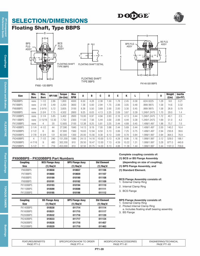
Floating Shaft, Type BBPS
U
T
FLOATING SHAFT DETAIL
ASSY
BS FLG
ASSY
BPS FLG
DED
B
KL C
FLOATING SHAFT
TYPE BBPS
A
FLOATING SHAFT
TYPE BBPS
FLG
ASSY
BPS
L
DD
BCS
FLG
ASSY
B
E
C K
PX60 -120 BBPSPX140-320 BBPS
PX60BBPS - PX320BBPS Part NumbersComplete coupling consists of:
(1) BCS or BS Flange Assembly
(depending on size of coupling),
(1) BPS Flange Assembly, and
(1) Standard Element.
Coupling BCS Flange Assy BPS Flange Assy Std ElementSize (1) Req’d (1) Req’d (1) Req’d
PX60BBPS 010658 010657 011106PX70BBPS 010660 010659 011107PX80BBPS 010189 010190 011108
BCS Flange Assembly consists of:1. External Clamp Ring
2. Internal Clamp Ring
3. BCS Flange
PX90BBPS 010191 010192 011109PX100BBPS 010193 010194 011110PX110BBPS 010599 010598 011111PX120BBPS 010195 010196 011112
Coupling BS Flange Assy BPS Flange Assy Std Element BPS Flange Assembly consists of:1. External Clamp Ring2. Piloted Internal Clamp Ring a. Includes floating shaft bearing assembly3. BS Flange
Size (1) Req’d (1) Req’d (1) Req’dPX140BBPS 010530 011714 011114PX160BBPS 010531 011715 011117PX200BBPS 010532 011716 011120PX240BBPS 010533 011717 011124PX280BBPS 010528 011718 011457PX320BBPS 010529 011719 011463
Size Min.Bore
Max.Bore HP/100 Torque
(In-Lbs)MaxRPM A B C D E K L T U Weight
(Lbs)Inertia(Lb-Ft2)
PX60BBPS none 1-1/2 2.86 1,800 4000 6.50 4.28 2.38 1.50 1.78 2.45 0.58 .624/.6225 1.28 9.8 0.21
PX70BBPS none 2-1/8 3.49 2,200 3600 7.38 5.00 2.94 1.75 2.06 3.05 0.48 .999/.9975 1.58 14.6 0.32
PX80BBPS none 2-9/16 5.72 3,605 3100 8.38 5.50 3.69 2.00 2.00 3.30 0.45 .999/.9975 1.58 26.9 0.79
PX90BBPS none 2-3/4 7.15 4,502 2800 9.25 6.03 4.13 2.25 2.09 3.67 0.39 1.249/1.2475 1.70 29.0 1.4
PX100BBPS none 3-1/4 5.85 5,402 2600 10.00 6.97 4.94 2.63 2.16 4.13 0.44 1.249/1.2475 1.72 40.1 2.5
PX110BBPS none 3-15/16 12.30 7,750 2300 11.00 7.56 5.44 3.00 2.06 4.44 0.38 1.249/1.2475 1.69 51.0 4.2
PX120BBPS none 4 20 12,605 2100 12.38 8.25 5.81 3.25 2.44 4.89 0.45 1.499/1.497 1.98 75.7 7.0
PX140BBPS 2-1/4 4-1/2 44 27,590 1840 14.13 9.19 7.00 3.88 2.44 5.69 0.44 1.499/1.497 2.00 140.2 16.4
PX160BBPS 2-1/2 6 60 37,800 1560 16.63 12.94 8.50 5.13 3.06 7.25 0.75 1.499/1.497 2.94 230.8 39.6
PX200BBPS 2-7/8 6-3/4 131 82,500 1300 20.00 15.56 9.38 6.13 3.69 8.78 0.84 1.999/1.997 2.84 364.5 76.9
PX240BBPS 4 7-1/2 240 151,200 1080 24.13 14.16 10.00 5.13 4.28 8.06 1.16 1.999/1.997 3.12 529.0 188.1
PX280BBPS 4-7/16 9 480 302,200 910 28.50 18.47 12.00 7.13 4.59 10.22 1.31 1.999/1.997 3.28 877.0 440.8
PX320BBPS 5-1/2 11 719 453,000 810 32.50 20.75 14.00 8.13 4.88 11.38 1.44 1.999/1.997 3.44 1181.0 709.6
PT1-29
PT
Co
mp
on
en
t R
efe
ren
ce
Gu
ide
Co
up
ling
sC
lutc
hes
an
d B
rake
sF
LE
XID
YN
EF
luid
Co
up
ling
sT
OR
QU
E-T
AM
ER
Bu
shin
gs
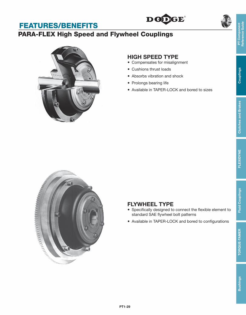
FEATURES/BENEFITSPARA-FLEX High Speed and Flywheel Couplings
HIGH SPEED TYPE Compensates for misalignment
Cushions thrust loads
Absorbs vibration and shock
Prolongs bearing life
Available in TAPER-LOCK and bored to sizes
FLYWHEEL TYPE Specifically designed to connect the flexible element to
standard SAE flywheel bolt patterns
Available in TAPER-LOCK and bored to configurations
PT1-30
SELECTION/DIMENSIONS
PT
Co
mp
on
en
t R
efe
ren
ce G
uid
eC
ou
plin
gs
Clu
tch
es an
d B
rakesF
LE
XID
YN
EF
luid
Co
up
ling
sT
OR
QU
E-TA
ME
RB
ush
ing
s
FEATURES/BENEFITS PAGE PT1-29
SELECTION/DIMENSION PAGE PT1-30
MODIFICATION/ACCESSORIES PAGE PT1-81
ENGINEERING/TECHNICAL PAGE PT1-83
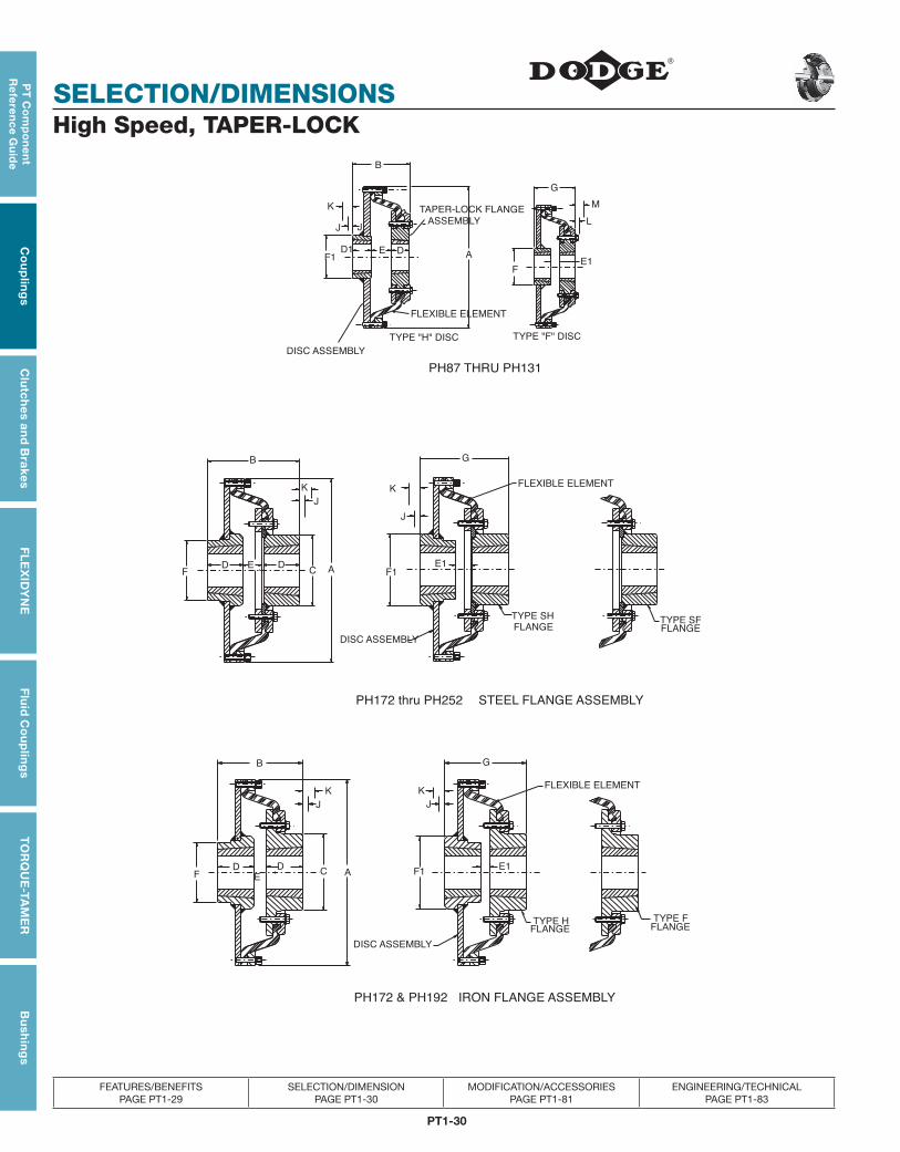
High Speed, TAPER-LOCK
E1
D1 DEA
TAPER-LOCK FLANGE
DISC ASSEMBLY
TYPE "F" DISCTYPE "H" DISC
J
G
B
M
L
STEEL FLANGE ASSEMBLYPH172 thru PH252
FLEXIBLE ELEMENT
DISC ASSEMBLY
FLANGETYPE SF
FLANGE
TYPE SH
J
K
EF1
DF C A
B
K
J
D E1
G
DISC ASSEMBLY
FLEXIBLE ELEMENT
C
FLANGETYPE H
J
K
E1F1A
J
K
E
FLANGETYPE F
DF
D
B G
IRON FLANGE ASSEMBLYPH172 & PH192
PH87 THRU PH131
K
J
F1
ASSEMBLY
FLEXIBLE ELEMENT
F
PT1-31
PT
Co
mp
on
en
t R
efe
ren
ce
Gu
ide
Co
up
ling
sC
lutc
hes
an
d B
rake
sF
LE
XID
YN
EF
luid
Co
up
ling
sT
OR
QU
E-T
AM
ER
Bu
shin
gs
SELECTION/DIMENSIONS
FEATURES/BENEFITS PAGE PT1-29
SELECTION/DIMENSION PAGE PT1-30
MODIFICATION/ACCESSORIES PAGE PT1-81
ENGINEERING/TECHNICAL PAGE PT1-83
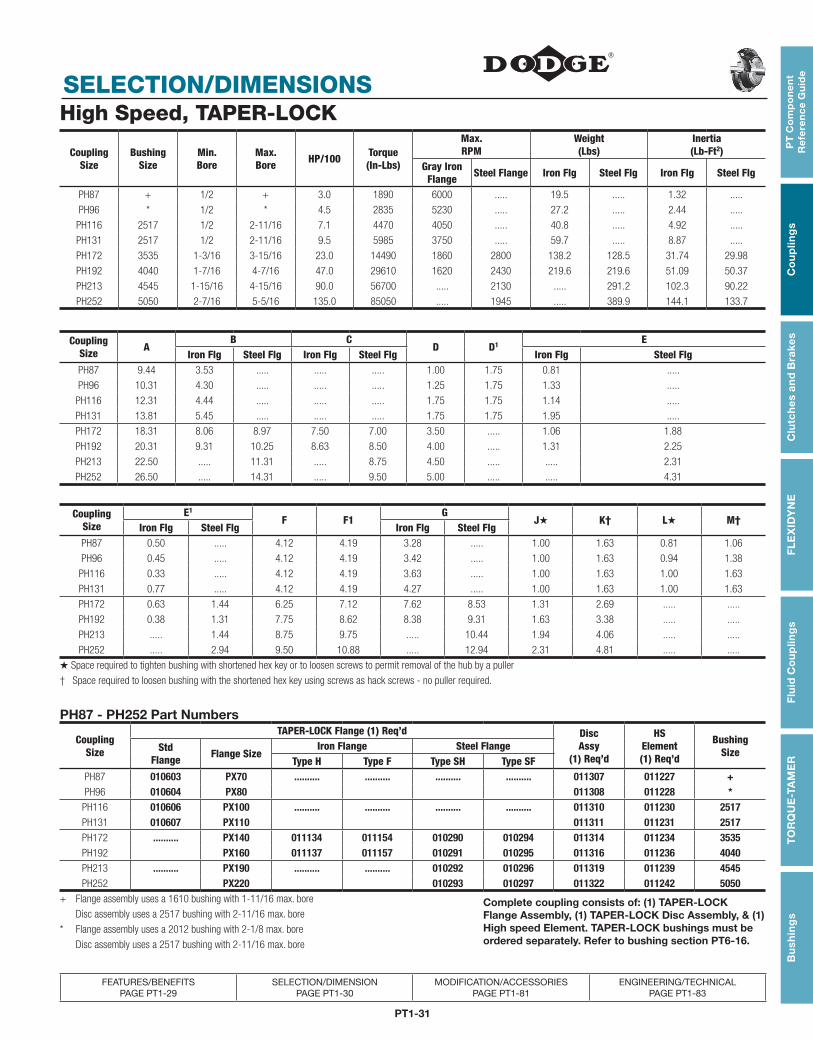
High Speed, TAPER-LOCK
Coupling Size
Bushing Size
Min.Bore
Max.Bore HP/100 Torque
(In-Lbs)
Max. RPM
Weight(Lbs)
Inertia(Lb-Ft2)
Gray Iron Flange Steel Flange Iron Flg Steel Flg Iron Flg Steel Flg
PH87 + 1/2 + 3.0 1890 6000 ..... 19.5 ..... 1.32 .....
PH96 * 1/2 * 4.5 2835 5230 ..... 27.2 ..... 2.44 .....
PH116 2517 1/2 2-11/16 7.1 4470 4050 ..... 40.8 ..... 4.92 .....
PH131 2517 1/2 2-11/16 9.5 5985 3750 ..... 59.7 ..... 8.87 .....
PH172 3535 1-3/16 3-15/16 23.0 14490 1860 2800 138.2 128.5 31.74 29.98
PH192 4040 1-7/16 4-7/16 47.0 29610 1620 2430 219.6 219.6 51.09 50.37
PH213 4545 1-15/16 4-15/16 90.0 56700 ..... 2130 ..... 291.2 102.3 90.22
PH252 5050 2-7/16 5-5/16 135.0 85050 ..... 1945 ..... 389.9 144.1 133.7
PH87 - PH252 Part Numbers
CouplingSize
TAPER-LOCK Flange (1) Req’d Disc Assy
(1) Req’d
HS Element(1) Req’d
BushingSizeStd
Flange Flange SizeIron Flange Steel Flange
Type H Type F Type SH Type SFPH87 010603 PX70 .......... .......... .......... .......... 011307 011227 +PH96 010604 PX80 011308 011228 *
PH116 010606 PX100 .......... .......... .......... .......... 011310 011230 2517PH131 010607 PX110 011311 011231 2517PH172 .......... PX140 011134 011154 010290 010294 011314 011234 3535PH192 PX160 011137 011157 010291 010295 011316 011236 4040PH213 .......... PX190 .......... .......... 010292 010296 011319 011239 4545PH252 PX220 010293 010297 011322 011242 5050
+ Flange assembly uses a 1610 bushing with 1-11/16 max. bore Complete coupling consists of: (1) TAPER-LOCK Flange Assembly, (1) TAPER-LOCK Disc Assembly, & (1) High speed Element. TAPER-LOCK bushings must be ordered separately. Refer to bushing section PT6-16.
Disc assembly uses a 2517 bushing with 2-11/16 max. bore
* Flange assembly uses a 2012 bushing with 2-1/8 max. bore
Disc assembly uses a 2517 bushing with 2-11/16 max. bore
CouplingSize
E1
F F1G
J★ K† L★ M†Iron Flg Steel Flg Iron Flg Steel Flg
PH87 0.50 ..... 4.12 4.19 3.28 ..... 1.00 1.63 0.81 1.06
PH96 0.45 ..... 4.12 4.19 3.42 ..... 1.00 1.63 0.94 1.38
PH116 0.33 ..... 4.12 4.19 3.63 ..... 1.00 1.63 1.00 1.63
PH131 0.77 ..... 4.12 4.19 4.27 ..... 1.00 1.63 1.00 1.63
PH172 0.63 1.44 6.25 7.12 7.62 8.53 1.31 2.69 ..... .....
PH192 0.38 1.31 7.75 8.62 8.38 9.31 1.63 3.38 ..... .....
PH213 ..... 1.44 8.75 9.75 ..... 10.44 1.94 4.06 ..... .....
PH252 ..... 2.94 9.50 10.88 ..... 12.94 2.31 4.81 ..... .....
★ Space required to tighten bushing with shortened hex key or to loosen screws to permit removal of the hub by a puller
† Space required to loosen bushing with the shortened hex key using screws as hack screws - no puller required.
CouplingSize A
B CD D1 E
Iron Flg Steel Flg Iron Flg Steel Flg Iron Flg Steel FlgPH87 9.44 3.53 ..... ..... ..... 1.00 1.75 0.81 .....
PH96 10.31 4.30 ..... ..... ..... 1.25 1.75 1.33 .....
PH116 12.31 4.44 ..... ..... ..... 1.75 1.75 1.14 .....
PH131 13.81 5.45 ..... ..... ..... 1.75 1.75 1.95 .....
PH172 18.31 8.06 8.97 7.50 7.00 3.50 ..... 1.06 1.88
PH192 20.31 9.31 10.25 8.63 8.50 4.00 ..... 1.31 2.25
PH213 22.50 ..... 11.31 ..... 8.75 4.50 ..... ..... 2.31
PH252 26.50 ..... 14.31 ..... 9.50 5.00 ..... ..... 4.31
PT1-32
SELECTION/DIMENSIONS
PT
Co
mp
on
en
t R
efe
ren
ce G
uid
eC
ou
plin
gs
Clu
tch
es an
d B
rakesF
LE
XID
YN
EF
luid
Co
up
ling
sT
OR
QU
E-TA
ME
RB
ush
ing
s
FEATURES/BENEFITS PAGE PT1-29
SELECTION/DIMENSION PAGE PT1-30
MODIFICATION/ACCESSORIES PAGE PT1-81
ENGINEERING/TECHNICAL PAGE PT1-83
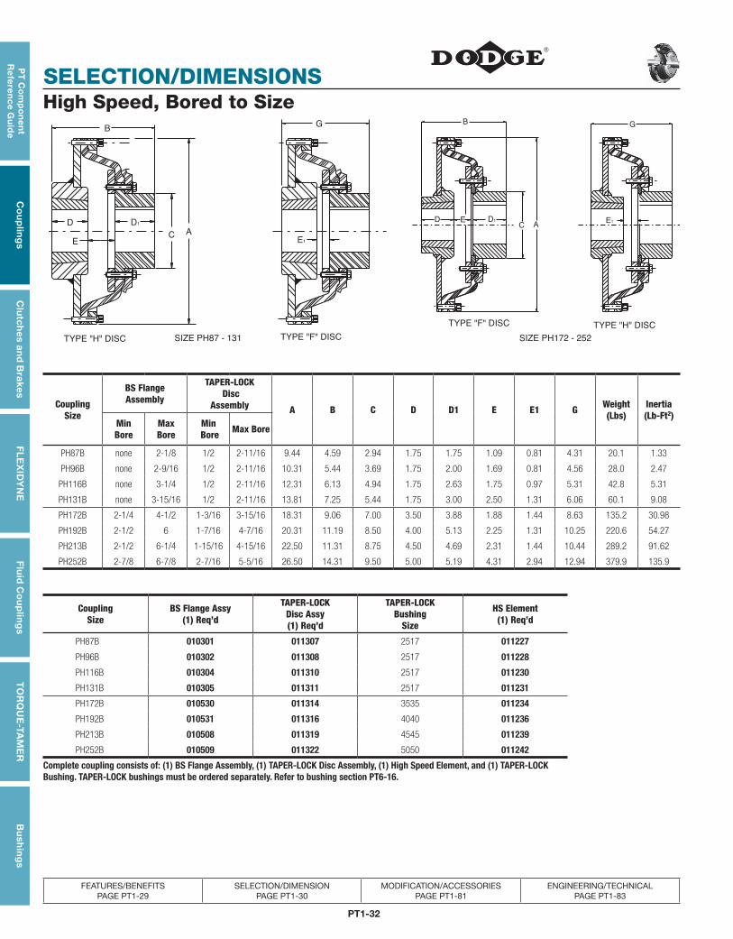
High Speed, Bored to Size
A
TYPE "H" DISC
B
E1
G
C
D1
E
D
TYPE "F" DISC
TYPE "F" DISC TYPE "H" DISC
SIZE PH87 - 131 SIZE PH172 - 252
D EC A
B
D1
G
E1
CouplingSize
BS FlangeAssembly
TAPER-LOCK Disc
Assembly A B C D D1 E E1 G Weight(Lbs)
Inertia(Lb-Ft2)
Min Bore
Max Bore
Min Bore Max Bore
PH87B none 2-1/8 1/2 2-11/16 9.44 4.59 2.94 1.75 1.75 1.09 0.81 4.31 20.1 1.33
PH96B none 2-9/16 1/2 2-11/16 10.31 5.44 3.69 1.75 2.00 1.69 0.81 4.56 28.0 2.47
PH116B none 3-1/4 1/2 2-11/16 12.31 6.13 4.94 1.75 2.63 1.75 0.97 5.31 42.8 5.31
PH131B none 3-15/16 1/2 2-11/16 13.81 7.25 5.44 1.75 3.00 2.50 1.31 6.06 60.1 9.08
PH172B 2-1/4 4-1/2 1-3/16 3-15/16 18.31 9.06 7.00 3.50 3.88 1.88 1.44 8.63 135.2 30.98
PH192B 2-1/2 6 1-7/16 4-7/16 20.31 11.19 8.50 4.00 5.13 2.25 1.31 10.25 220.6 54.27
PH213B 2-1/2 6-1/4 1-15/16 4-15/16 22.50 11.31 8.75 4.50 4.69 2.31 1.44 10.44 289.2 91.62
PH252B 2-7/8 6-7/8 2-7/16 5-5/16 26.50 14.31 9.50 5.00 5.19 4.31 2.94 12.94 379.9 135.9
CouplingSize
BS Flange Assy(1) Req’d
TAPER-LOCK Disc Assy(1) Req’d
TAPER-LOCK Bushing
Size
HS Element(1) Req’d
PH87B 010301 011307 2517 011227
PH96B 010302 011308 2517 011228
PH116B 010304 011310 2517 011230
PH131B 010305 011311 2517 011231
PH172B 010530 011314 3535 011234
PH192B 010531 011316 4040 011236
PH213B 010508 011319 4545 011239
PH252B 010509 011322 5050 011242
Complete coupling consists of: (1) BS Flange Assembly, (1) TAPER-LOCK Disc Assembly, (1) High Speed Element, and (1) TAPER-LOCK Bushing. TAPER-LOCK bushings must be ordered separately. Refer to bushing section PT6-16.
PT1-33
PT
Co
mp
on
en
t R
efe
ren
ce
Gu
ide
Co
up
ling
sC
lutc
hes
an
d B
rake
sF
LE
XID
YN
EF
luid
Co
up
ling
sT
OR
QU
E-T
AM
ER
Bu
shin
gs
SELECTION/DIMENSIONS
FEATURES/BENEFITS PAGE PT1-29
SELECTION/DIMENSION PAGE PT1-30
MODIFICATION/ACCESSORIES PAGE PT1-81
ENGINEERING/TECHNICAL PAGE PT1-83
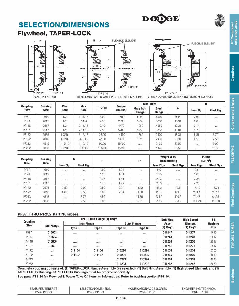
Flywheel, TAPER-LOCKFLEXIBLE ELEMENT
IRON FLANGE AND CLAMP RING STEEL FLANGE AND CLAMP RINGSIZES PF87-PF131 SIZES PF172-PF192 SIZES PF172-PF252
B
TYPE "H"TYPE "F"
E D
B
E
DC A
TYPE "H"
TYPE "F"
E1
D
B
C A D
TYPE "SH"
TYPE "SF"
FLEXIBLE ELEMENT
Coupling Size
Bushing Size
Min.Bore
Max.Bore HP/100 Torque
(In-Lbs)
Max. RPMA
BGray IronFlange
SteelFlange Iron Flg. Steel Flg.
PF87 1610 1/2 1-11/16 3.00 1890 6000 6000 9.44 2.69 .....
PF96 2012 1/2 2-1/8 4.50 2835 5230 5230 10.31 2.83 .....
PF116 2517 1/2 2-11/16 7.10 4470 4050 4050 12.31 3.14 .....
PF131 2517 1/2 2-11/16 9.50 5985 3750 3750 13.81 3.70 .....
PF172 3535 1-3/16 3-15/16 23.00 14490 1860 2800 18.31 5.81 6.72
PF192 4040 1-7/16 4-7/16 47.00 29610 1620 2430 20.31 6.56 7.50
PF213 4545 1-15/16 4-15/16 90.00 56700 ..... 2130 22.50 ..... 9.00
PF252 5050 2-7/16 5-5/16 135.00 85050 ..... 1945 26.50 ..... 10.81
CouplingSize
BushingSize
CD E E1
Weight (Lbs)Less Bushing
Inertia(Lb-Ft2)
Iron Flg. Steel Flg. Iron Flgs Steel Flgs Iron Flgs Steel FlgsPF87 1610 ..... ..... 1.00 1.34 .... 9.9 ..... 0.6 .....
PF96 2012 ..... ..... 1.25 1.58 .... 13.5 ..... 1.05 .....
PF116 2517 ..... ..... 1.75 1.39 .... 22.3 ..... 2.35 .....
PF131 2517 ..... ..... 1.75 1.95 .... 33.3 ..... 4.35 .....
PF172 3535 7.50 7.00 3.50 2.31 3.12 87.2 77.5 17.49 15.73
PF192 4040 8.63 8.50 4.00 2.56 3.50 128.6 128.6 28.84 28.12
PF213 4545 ..... 8.75 4.50 - 4.50 221.2 190.2 74.47 64.36
PF252 5050 ..... 9.50 5.00 - 5.81 297.9 260.9 121.79 111.38
PF87 THRU PF252 Part Numbers
CouplingSize
TAPER-LOCK Flange (1) Req’d Bolt RingAssy
(1) Req’d
High SpeedElement(1) Req’d
T-LBushing
SizeStd FlangeIron Flange Steel Flange
Type H Type F Type SH Type SFPF87 010603 ..... ..... ..... ..... 011247 011227 1610
PF96 010604 ..... ..... ..... ..... 011248 011228 2012
PF116 010606 ..... ..... ..... ..... 011250 011230 2517
PF131 010607 ..... ..... ..... ..... 011251 011231 2517
PF172 ..... 011134 011154 010290 010294 011254 011234 3535
PF192 ..... 011137 011157 010291 010295 011256 011236 4040
PF213 ..... ..... ..... 010292 010296 011259 011239 4545
PF252 ..... ..... ..... 010293 010297 011262 011242 5050
Complete coupling consists of: (1) TAPER-LOCK Flange Assembly (as selected), (1) Bolt Ring Assembly, (1) High Speed Element, and (1) TAPER-LOCK Bushing. TAPER-LOCK Bushings must be ordered separately.See page PT1-34 for Flywheel & Power Take Off housing information. Refer to bushing section PT6-16.
PT1-34
SELECTION/DIMENSIONS
PT
Co
mp
on
en
t R
efe
ren
ce G
uid
eC
ou
plin
gs
Clu
tch
es an
d B
rakesF
LE
XID
YN
EF
luid
Co
up
ling
sT
OR
QU
E-TA
ME
RB
ush
ing
s
FEATURES/BENEFITS PAGE PT1-29
SELECTION/DIMENSION PAGE PT1-30
MODIFICATION/ACCESSORIES PAGE PT1-81
ENGINEERING/TECHNICAL PAGE PT1-83
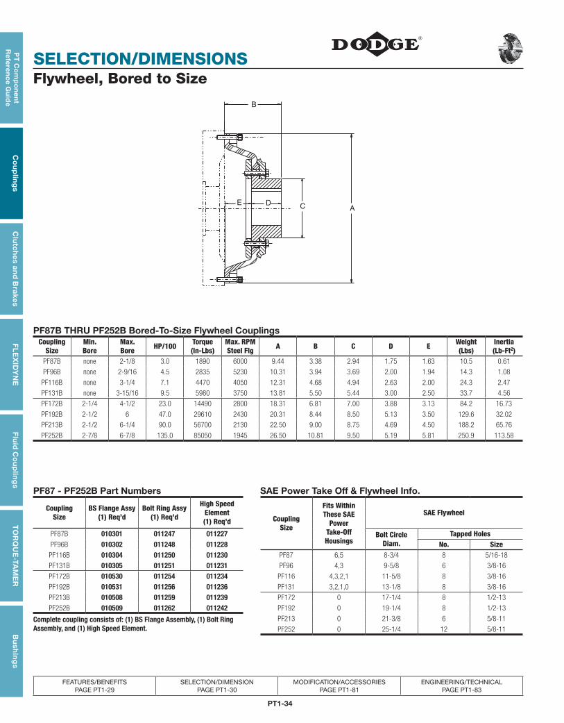
Flywheel, Bored to Size
EC
B
AD
PF87B THRU PF252B Bored-To-Size Flywheel CouplingsCoupling
SizeMin.Bore
Max. Bore HP/100 Torque
(In-Lbs)Max. RPMSteel Flg A B C D E Weight
(Lbs)Inertia(Lb-Ft2)
PF87B none 2-1/8 3.0 1890 6000 9.44 3.38 2.94 1.75 1.63 10.5 0.61
PF96B none 2-9/16 4.5 2835 5230 10.31 3.94 3.69 2.00 1.94 14.3 1.08
PF116B none 3-1/4 7.1 4470 4050 12.31 4.68 4.94 2.63 2.00 24.3 2.47
PF131B none 3-15/16 9.5 5980 3750 13.81 5.50 5.44 3.00 2.50 33.7 4.56
PF172B 2-1/4 4-1/2 23.0 14490 2800 18.31 6.81 7.00 3.88 3.13 84.2 16.73
PF192B 2-1/2 6 47.0 29610 2430 20.31 8.44 8.50 5.13 3.50 129.6 32.02
PF213B 2-1/2 6-1/4 90.0 56700 2130 22.50 9.00 8.75 4.69 4.50 188.2 65.76
PF252B 2-7/8 6-7/8 135.0 85050 1945 26.50 10.81 9.50 5.19 5.81 250.9 113.58
PF87 - PF252B Part Numbers SAE Power Take Off & Flywheel Info.
CouplingSize
BS Flange Assy(1) Req’d
Bolt Ring Assy(1) Req’d
High Speed Element(1) Req’d Coupling
Size
Fits Within These SAE
Power Take-Off Housings
SAE Flywheel
PF87B 010301 011247 011227 Bolt Circle Diam.
Tapped HolesPF96B 010302 011248 011228 No. Size
PF116B 010304 011250 011230 PF87 6,5 8-3/4 8 5/16-18
PF131B 010305 011251 011231 PF96 4,3 9-5/8 6 3/8-16
PF172B 010530 011254 011234 PF116 4,3,2,1 11-5/8 8 3/8-16
PF192B 010531 011256 011236 PF131 3,2,1,0 13-1/8 8 3/8-16
PF213B 010508 011259 011239 PF172 0 17-1/4 8 1/2-13
PF252B 010509 011262 011242 PF192 0 19-1/4 8 1/2-13
Complete coupling consists of: (1) BS Flange Assembly, (1) Bolt Ring Assembly, and (1) High Speed Element.
PF213 0 21-3/8 6 5/8-11
PF252 0 25-1/4 12 5/8-11
FEATURES/BENEFITS
PT1-35
PT
Co
mp
on
en
t R
efe
ren
ce
Gu
ide
Co
up
ling
sC
lutc
hes
an
d B
rake
sF
LE
XID
YN
EF
luid
Co
up
ling
sT
OR
QU
E-T
AM
ER
Bu
shin
gs
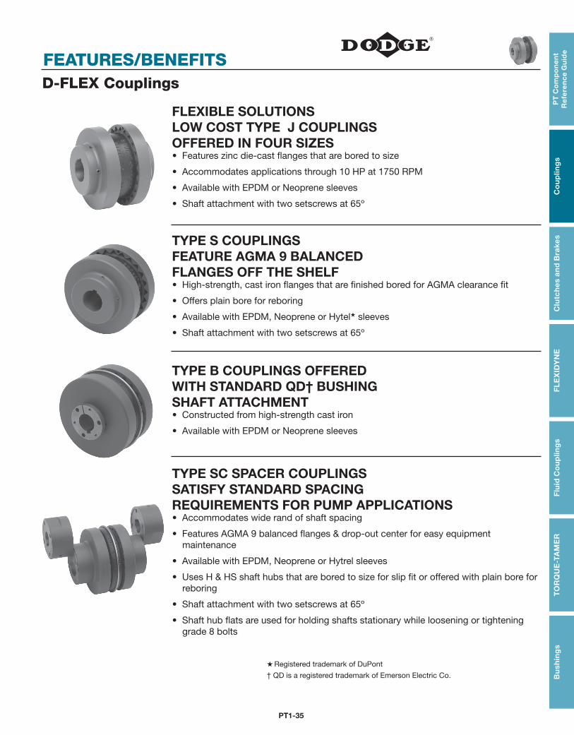
D-FLEX Couplings
FLEXIBLE SOLUTIONS LOW COST TYPE J COUPLINGS OFFERED IN FOUR SIZES• Features zinc die-cast flanges that are bored to size
• Accommodates applications through 10 HP at 1750 RPM
• Available with EPDM or Neoprene sleeves
• Shaft attachment with two setscrews at 65º
TYPE S COUPLINGS FEATURE AGMA 9 BALANCED FLANGES OFF THE SHELF• High-strength, cast iron flanges that are finished bored for AGMA clearance fit
• Offers plain bore for reboring
• Available with EPDM, Neoprene or Hytel★ sleeves
• Shaft attachment with two setscrews at 65º
TYPE B COUPLINGS OFFERED WITH STANDARD QD† BUSHING SHAFT ATTACHMENT• Constructed from high-strength cast iron
• Available with EPDM or Neoprene sleeves
TYPE SC SPACER COUPLINGS SATISFY STANDARD SPACING REQUIREMENTS FOR PUMP APPLICATIONS• Accommodates wide rand of shaft spacing
• Features AGMA 9 balanced flanges & drop-out center for easy equipment maintenance
• Available with EPDM, Neoprene or Hytrel sleeves
• Uses H & HS shaft hubs that are bored to size for slip fit or offered with plain bore for reboring
• Shaft attachment with two setscrews at 65º
• Shaft hub flats are used for holding shafts stationary while loosening or tightening grade 8 bolts
★ Registered trademark of DuPont
† QD is a registered trademark of Emerson Electric Co.
PT1-36
FEATURES/BENEFITS
PT
Co
mp
on
en
t R
efe
ren
ce G
uid
eC
ou
plin
gs
Clu
tch
es an
d B
rakesF
LE
XID
YN
EF
luid
Co
up
ling
sT
OR
QU
E-TA
ME
RB
ush
ing
s
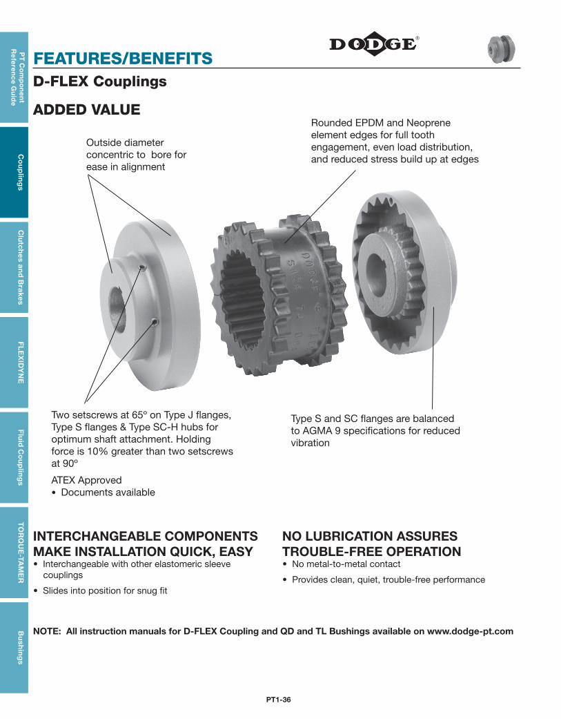
D-FLEX Couplings
ADDED VALUE
Outside diameter concentric to bore for ease in alignment
Rounded EPDM and Neoprene element edges for full tooth engagement, even load distribution, and reduced stress build up at edges
Two setscrews at 65º on Type J flanges, Type S flanges & Type SC-H hubs for optimum shaft attachment. Holding force is 10% greater than two setscrews at 90º
ATEX Approved • Documents available
Type S and SC flanges are balanced to AGMA 9 specifications for reduced vibration
INTERCHANGEABLE COMPONENTS MAKE INSTALLATION QUICK, EASY• Interchangeable with other elastomeric sleeve
couplings
• Slides into position for snug fit
NO LUBRICATION ASSURES TROUBLE-FREE OPERATION• No metal-to-metal contact
• Provides clean, quiet, trouble-free performance
NOTE: All instruction manuals for D-FLEX Coupling and QD and TL Bushings available on www.dodge-pt.com
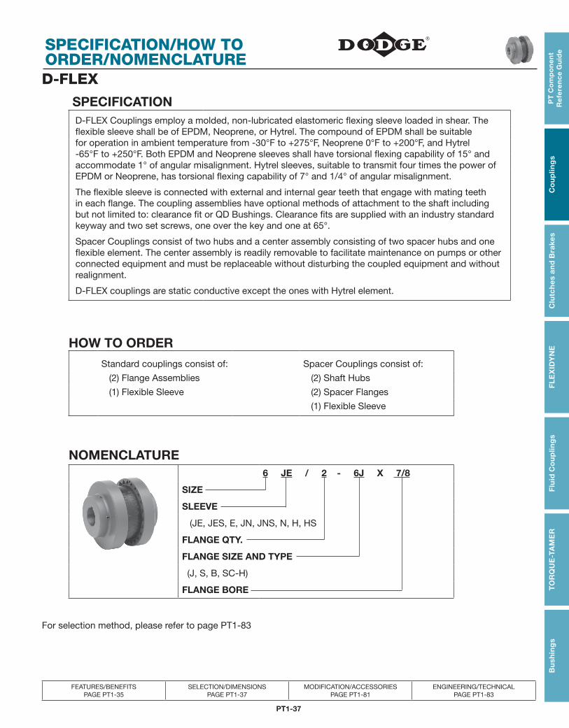
PT1-37
PT
Co
mp
on
en
t R
efe
ren
ce
Gu
ide
Co
up
ling
sC
lutc
hes
an
d B
rake
sF
LE
XID
YN
EF
luid
Co
up
ling
sT
OR
QU
E-T
AM
ER
Bu
shin
gs
SPECIFICATION/HOW TO ORDER/NOMENCLATURE
FEATURES/BENEFITS PAGE PT1-35
SELECTION/DIMENSIONSPAGE PT1-37
MODIFICATION/ACCESSORIES PAGE PT1-81
ENGINEERING/TECHNICAL PAGE PT1-83
D-FLEX
SPECIFICATIOND-FLEX Couplings employ a molded, non-lubricated elastomeric flexing sleeve loaded in shear. The flexible sleeve shall be of EPDM, Neoprene, or Hytrel. The compound of EPDM shall be suitable for operation in ambient temperature from -30°F to +275°F, Neoprene 0°F to +200°F, and Hytrel -65°F to +250°F. Both EPDM and Neoprene sleeves shall have torsional flexing capability of 15° and accommodate 1° of angular misalignment. Hytrel sleeves, suitable to transmit four times the power of EPDM or Neoprene, has torsional flexing capability of 7° and 1/4° of angular misalignment.
The flexible sleeve is connected with external and internal gear teeth that engage with mating teeth in each flange. The coupling assemblies have optional methods of attachment to the shaft including but not limited to: clearance fit or QD Bushings. Clearance fits are supplied with an industry standard keyway and two set screws, one over the key and one at 65°.
Spacer Couplings consist of two hubs and a center assembly consisting of two spacer hubs and one flexible element. The center assembly is readily removable to facilitate maintenance on pumps or other connected equipment and must be replaceable without disturbing the coupled equipment and without realignment.
D-FLEX couplings are static conductive except the ones with Hytrel element.
HOW TO ORDER
Standard couplings consist of: Spacer Couplings consist of:
(2) Flange Assemblies (2) Shaft Hubs
(1) Flexible Sleeve (2) Spacer Flanges
(1) Flexible Sleeve
NOMENCLATURE6 JE / 2 - 6J X 7/8
SIZE
SLEEVE
(JE, JES, E, JN, JNS, N, H, HS
FLANGE QTY.
FLANGE SIZE AND TYPE
(J, S, B, SC-H)
FLANGE BORE
For selection method, please refer to page PT1-83
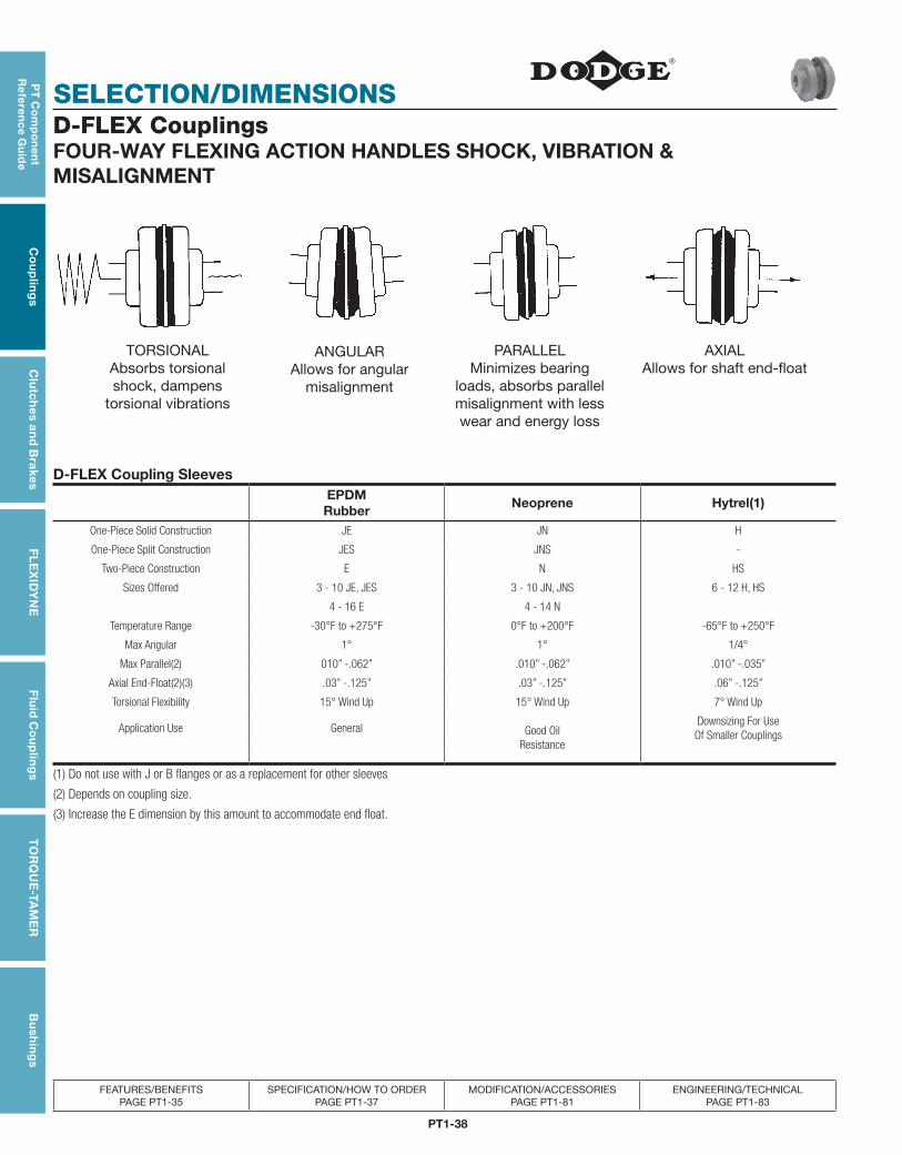
PT1-38
SELECTION/DIMENSIONS
PT
Co
mp
on
en
t R
efe
ren
ce G
uid
eC
ou
plin
gs
Clu
tch
es an
d B
rakesF
LE
XID
YN
EF
luid
Co
up
ling
sT
OR
QU
E-TA
ME
RB
ush
ing
s
FEATURES/BENEFITS PAGE PT1-35
SPECIFICATION/HOW TO ORDERPAGE PT1-37
MODIFICATION/ACCESSORIES PAGE PT1-81
ENGINEERING/TECHNICAL PAGE PT1-83
D-FLEX CouplingsFOUR-WAY FLEXING ACTION HANDLES SHOCK, VIBRATION & MISALIGNMENT
TORSIONALAbsorbs torsional shock, dampens
torsional vibrations
ANGULARAllows for angular
misalignment
PARALLELMinimizes bearing
loads, absorbs parallel misalignment with less wear and energy loss
AXIALAllows for shaft end-float
D-FLEX Coupling SleevesEPDMRubber
Neoprene Hytrel(1)
One-Piece Solid Construction JE JN H
One-Piece Split Construction JES JNS -
Two-Piece Construction E N HS
Sizes Offered 3 - 10 JE, JES 3 - 10 JN, JNS 6 - 12 H, HS
4 - 16 E 4 - 14 N
Temperature Range -30°F to +275°F 0°F to +200°F -65°F to +250°F
Max Angular 1° 1° 1/4°
Max Parallel(2) 010” -.062” .010” -.062” .010” -.035”
Axial End-Float(2)(3) .03” -.125” .03” -.125” .06” -.125”
Torsional Flexibility 15° Wind Up 15° Wind Up 7° Wind Up
Application Use General Good OilResistance
Downsizing For Use Of Smaller Couplings
(1) Do not use with J or B flanges or as a replacement for other sleeves
(2) Depends on coupling size.
(3) Increase the E dimension by this amount to accommodate end float.
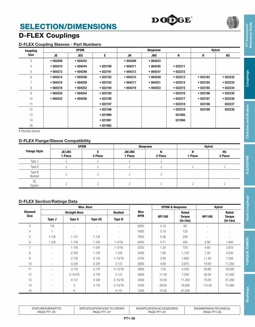
PT1-39
PT
Co
mp
on
en
t R
efe
ren
ce
Gu
ide
Co
up
ling
sC
lutc
hes
an
d B
rake
sF
LE
XID
YN
EF
luid
Co
up
ling
sT
OR
QU
E-T
AM
ER
Bu
shin
gs
SELECTION/DIMENSIONS
FEATURES/BENEFITS PAGE PT1-35
SPECIFICATION/HOW TO ORDERPAGE PT1-37
MODIFICATION/ACCESSORIES PAGE PT1-81
ENGINEERING/TECHNICAL PAGE PT1-83
D-FLEX CouplingsD-FLEX Coupling Sleeves - Part Numbers
CouplingSize
EPDM Neoprene Hytrel
JE JES E JN JNS N H HS
3 • 004208 • 004242 • 004209 • 004243
4 • 004210 • 004244 • 022190 • 004211 • 004245 • 022211
5 • 004212 • 004246 • 022191 • 004213 • 004247 • 022212
6 • 004214 • 004248 • 022192 • 004215 • 004249 • 022213 • 022183 • 022232
7 • 004216 • 004250 • 022193 • 004217 • 004251 • 022214 • 022184 • 022233
8 • 004218 • 004252 • 022194 • 004219 • 004253 • 022215 • 022185 • 022234
9 • 004220 • 004254 • 022195 • 022216 • 022186 • 022235
10 • 004222 • 004256 • 022196 • 022217 • 022187 • 022236
11 • 022197 • 022218 022188 022237
12 • 022198 • 022219 022189 022238
13 • 021990 021993
14 • 021991 021994
16 • 021992
• Stocked sleeves
D-FLEX Flange/Sleeve Compatibility
Flange StyleEPDM Neoprene Hytrel
JE/JES1 Piece
E2 Piece
JN/JNS1 Piece
N2 Piece
H1 Piece
HS2 Piece
Type J √ √ √ √
Type S √ √ √ √ √ √
Type BBushed
√ √ √ √
SCSpacer
√ √ √ √ √ √
D-FLEX Section/Ratings Data
Element Size
Max. BoreMax RPM
EPDM & Neoprene Hytrel
Straight Bore BushedHP/100
Rated Torque(In-Lbs)
HP/100RatedTorque(In-Lbs)Type J Type S Type SC Type B
3 7/8 - - - 9200 0.10 60 - -
4 1 - - - 7600 0.19 120 - -
5 1-1/8 1-1/4 1-1/8 - 7600 0.38 240 - -
6 1-3/8 1-7/8 1-3/8 1-3/16 6000 0.71 450 2.90 1,800
7 - 1-7/8 1-5/8 1-3/16 5250 1.20 725 4.60 2,875
8 - 2-3/8 1-7/8 1-5/8 4500 1.80 1,135 7.20 4,530
9 - 2-7/8 2-1/8 1-15/16 3750 2.80 1,800 11.40 7,200
10 - 3-3/8 2-3/8 2-1/2 3600 4.60 2,875 18.00 11,350
11 - 3-7/8 2-7/8 2-13/16 3600 7.20 4,530 28.60 18,000
12 - 3-15/16 2-7/8 3-1/2 2800 11.40 7,200 50.00 31,500
13 - 4-1/2 3-3/8 3-15/16 2400 18.00 11,350 75.00 47,268
14 - 5 3-7/8 3-15/16 2200 28.60 18,000 115.00 72,480
16 - 6 - 4-1/2 1500 75.00 47,250 - -
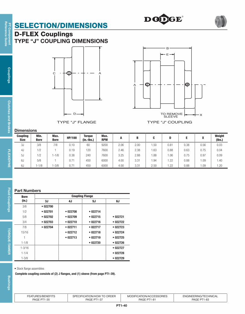
PT1-40
SELECTION/DIMENSIONS
PT
Co
mp
on
en
t R
efe
ren
ce G
uid
eC
ou
plin
gs
Clu
tch
es an
d B
rakesF
LE
XID
YN
EF
luid
Co
up
ling
sT
OR
QU
E-TA
ME
RB
ush
ing
s
FEATURES/BENEFITS PAGE PT1-35
SPECIFICATION/HOW TO ORDERPAGE PT1-37
MODIFICATION/ACCESSORIES PAGE PT1-81
ENGINEERING/TECHNICAL PAGE PT1-83
D-FLEX CouplingsTYPE “J” COUPLING DIMENSIONS
D
AC
TYPE "J" FLANGE SLEEVETO REMOVE X
E
B
A
TYPE "J" COUPLING
DimensionsCoupling
SizeMin. Bore
Max. Bore HP/100 Torque
(in.-lbs.)Max. RPM A B C D E X Weight
(lbs.)
3J 3/8 7/8 0.10 60 9200 2.06 2.00 1.50 0.81 0.38 0.56 0.03
4J 1/2 1 0.19 120 7600 2.46 2.38 1.63 0.88 0.63 0.75 0.04
5J 1/2 1-1/8 0.38 240 7600 3.25 2.88 1.88 1.06 0.75 0.97 0.09
6J 5/8 1 0.71 450 6000 4.00 3.31 1.94 1.22 0.88 1.09 1.40
6J 1-1/8 1-3/8 0.71 450 6000 4.00 3.31 2.50 1.22 0.88 1.09 1.20
Part NumbersBore(in.)
Coupling Flange
3J 4J 5J 6J
3/8 • 022700
1/2 • 022701 • 022708 • 022714
5/8 • 022702 • 022709 • 022715 • 022721
3/4 • 022703 • 022710 • 022716 • 022722
7/8 • 022704 • 022711 • 022717 • 022723
15/16 • 022712 • 022718 • 022724
1 • 022713 • 022719 • 022725
1-1/8 • 022720 • 022726
1-3/16 • 022727
1-1/4 • 022728
1-3/8 • 022729
• Stock flange assemblies
Complete coupling consists of (2) J flanges, and (1) sleeve (from page PT1-39).
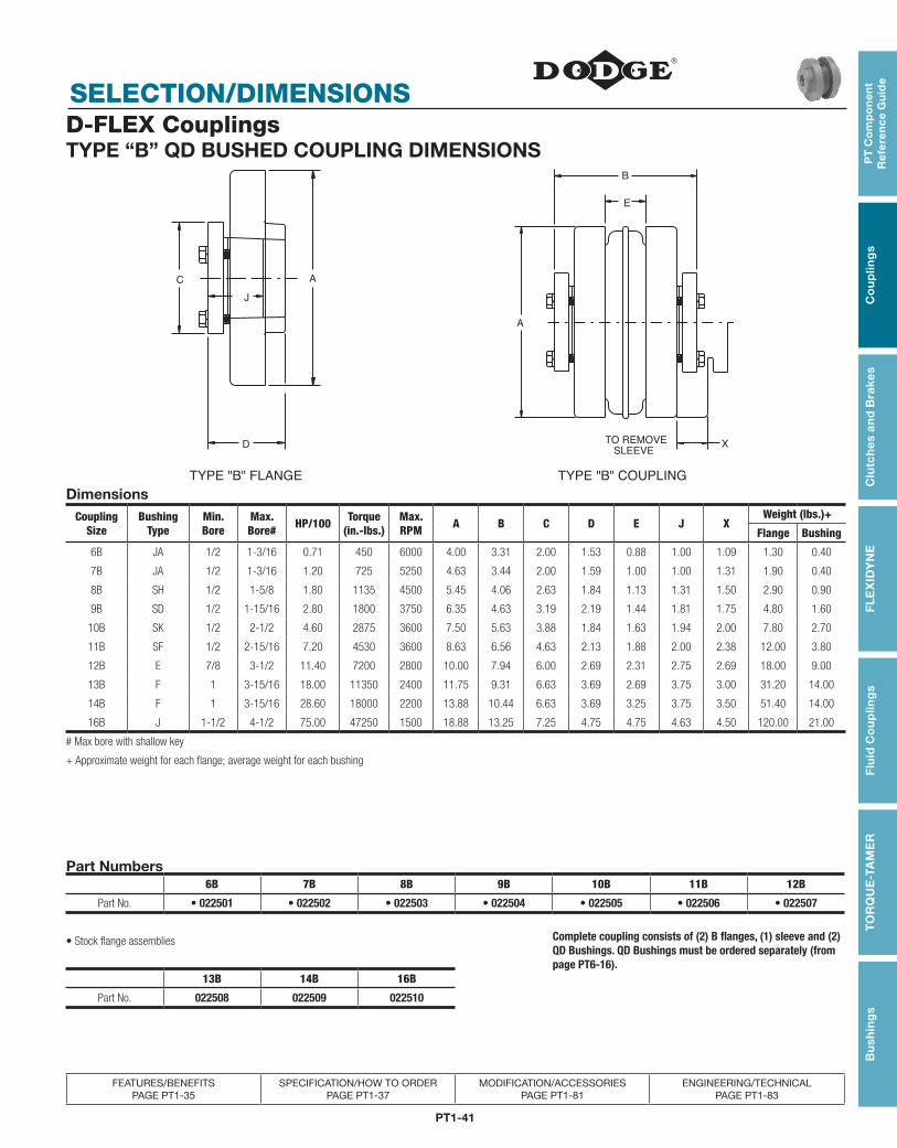
PT1-41
PT
Co
mp
on
en
t R
efe
ren
ce
Gu
ide
Co
up
ling
sC
lutc
hes
an
d B
rake
sF
LE
XID
YN
EF
luid
Co
up
ling
sT
OR
QU
E-T
AM
ER
Bu
shin
gs
SELECTION/DIMENSIONS
FEATURES/BENEFITS PAGE PT1-35
SPECIFICATION/HOW TO ORDERPAGE PT1-37
MODIFICATION/ACCESSORIES PAGE PT1-81
ENGINEERING/TECHNICAL PAGE PT1-83
D-FLEX CouplingsTYPE “B” QD BUSHED COUPLING DIMENSIONS
C
J
D
A
TYPE "B" FLANGE
SLEEVEX
TO REMOVE
B
E
A
TYPE "B" COUPLING
DimensionsCoupling
SizeBushing
TypeMin.Bore
Max.Bore# HP/100 Torque
(in.-lbs.)Max.RPM A B C D E J X
Weight (lbs.)+
Flange Bushing
6B JA 1/2 1-3/16 0.71 450 6000 4.00 3.31 2.00 1.53 0.88 1.00 1.09 1.30 0.40
7B JA 1/2 1-3/16 1.20 725 5250 4.63 3.44 2.00 1.59 1.00 1.00 1.31 1.90 0.40
8B SH 1/2 1-5/8 1.80 1135 4500 5.45 4.06 2.63 1.84 1.13 1.31 1.50 2.90 0.90
9B SD 1/2 1-15/16 2.80 1800 3750 6.35 4.63 3.19 2.19 1.44 1.81 1.75 4.80 1.60
10B SK 1/2 2-1/2 4.60 2875 3600 7.50 5.63 3.88 1.84 1.63 1.94 2.00 7.80 2.70
11B SF 1/2 2-15/16 7.20 4530 3600 8.63 6.56 4.63 2.13 1.88 2.00 2.38 12.00 3.80
12B E 7/8 3-1/2 11.40 7200 2800 10.00 7.94 6.00 2.69 2.31 2.75 2.69 18.00 9.00
13B F 1 3-15/16 18.00 11350 2400 11.75 9.31 6.63 3.69 2.69 3.75 3.00 31.20 14.00
14B F 1 3-15/16 28.60 18000 2200 13.88 10.44 6.63 3.69 3.25 3.75 3.50 51.40 14.00
16B J 1-1/2 4-1/2 75.00 47250 1500 18.88 13.25 7.25 4.75 4.75 4.63 4.50 120.00 21.00
# Max bore with shallow key
+ Approximate weight for each flange; average weight for each bushing
Part Numbers6B 7B 8B 9B 10B 11B 12B
Part No. • 022501 • 022502 • 022503 • 022504 • 022505 • 022506 • 022507
Complete coupling consists of (2) B flanges, (1) sleeve and (2) QD Bushings. QD Bushings must be ordered separately (from page PT6-16).
• Stock flange assemblies
13B 14B 16B
Part No. 022508 022509 022510
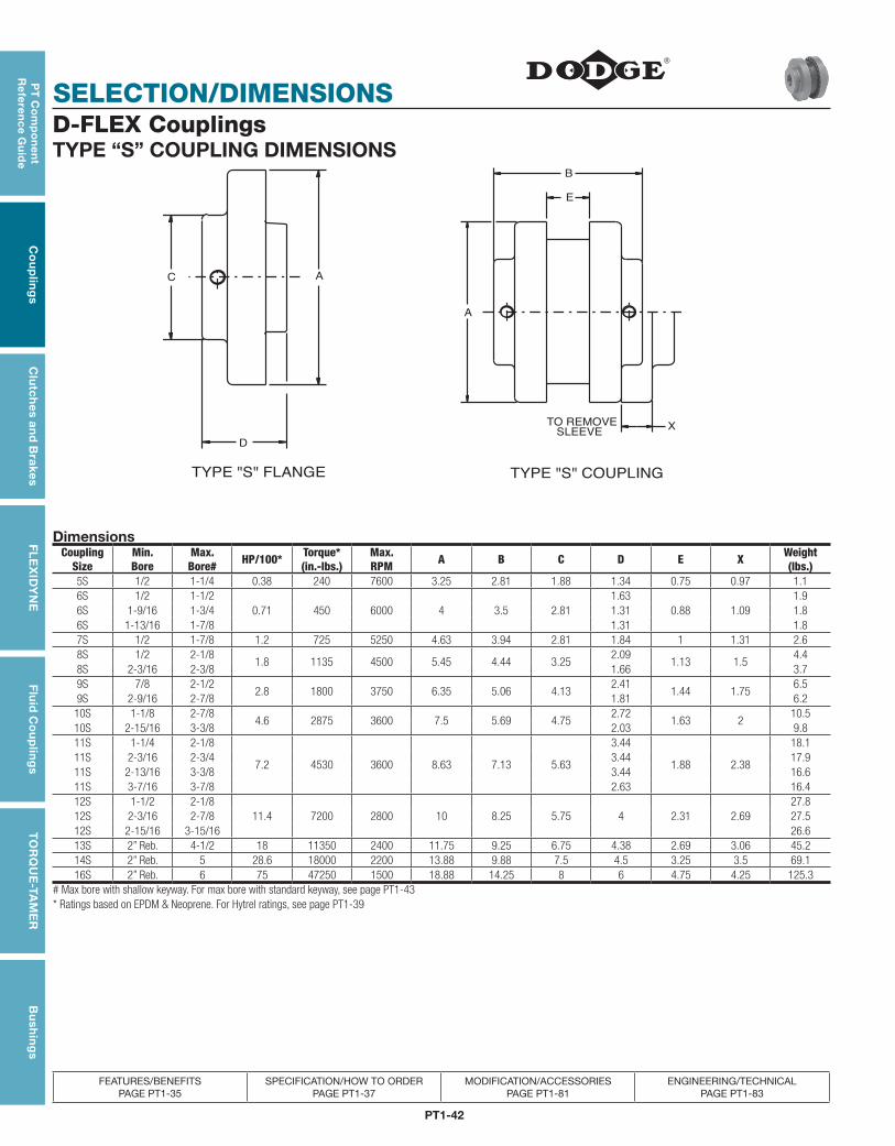
PT1-42
SELECTION/DIMENSIONS
PT
Co
mp
on
en
t R
efe
ren
ce G
uid
eC
ou
plin
gs
Clu
tch
es an
d B
rakesF
LE
XID
YN
EF
luid
Co
up
ling
sT
OR
QU
E-TA
ME
RB
ush
ing
s
FEATURES/BENEFITS PAGE PT1-35
SPECIFICATION/HOW TO ORDERPAGE PT1-37
MODIFICATION/ACCESSORIES PAGE PT1-81
ENGINEERING/TECHNICAL PAGE PT1-83
D-FLEX CouplingsTYPE “S” COUPLING DIMENSIONS
D
AC
TYPE "S" FLANGE
SLEEVETO REMOVE X
E
B
A
TYPE "S" COUPLING
DimensionsCoupling
SizeMin. Bore
Max. Bore# HP/100* Torque*
(in.-lbs.)Max.RPM A B C D E X Weight
(lbs.)5S 1/2 1-1/4 0.38 240 7600 3.25 2.81 1.88 1.34 0.75 0.97 1.16S 1/2 1-1/2
0.71 450 6000 4 3.5 2.811.63
0.88 1.091.9
6S 1-9/16 1-3/4 1.31 1.86S 1-13/16 1-7/8 1.31 1.87S 1/2 1-7/8 1.2 725 5250 4.63 3.94 2.81 1.84 1 1.31 2.68S 1/2 2-1/8
1.8 1135 4500 5.45 4.44 3.252.09
1.13 1.54.4
8S 2-3/16 2-3/8 1.66 3.79S 7/8 2-1/2
2.8 1800 3750 6.35 5.06 4.132.41
1.44 1.756.5
9S 2-9/16 2-7/8 1.81 6.210S 1-1/8 2-7/8
4.6 2875 3600 7.5 5.69 4.752.72
1.63 210.5
10S 2-15/16 3-3/8 2.03 9.811S 1-1/4 2-1/8
7.2 4530 3600 8.63 7.13 5.63
3.44
1.88 2.38
18.111S 2-3/16 2-3/4 3.44 17.911S 2-13/16 3-3/8 3.44 16.611S 3-7/16 3-7/8 2.63 16.412S 1-1/2 2-1/8
11.4 7200 2800 10 8.25 5.75 4 2.31 2.6927.8
12S 2-3/16 2-7/8 27.512S 2-15/16 3-15/16 26.613S 2” Reb. 4-1/2 18 11350 2400 11.75 9.25 6.75 4.38 2.69 3.06 45.214S 2” Reb. 5 28.6 18000 2200 13.88 9.88 7.5 4.5 3.25 3.5 69.116S 2” Reb. 6 75 47250 1500 18.88 14.25 8 6 4.75 4.25 125.3
# Max bore with shallow keyway. For max bore with standard keyway, see page PT1-43* Ratings based on EPDM & Neoprene. For Hytrel ratings, see page PT1-39
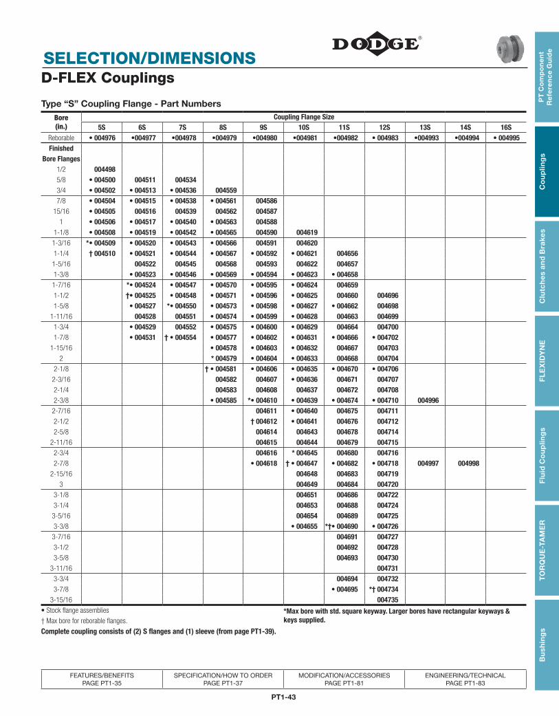
PT1-43
PT
Co
mp
on
en
t R
efe
ren
ce
Gu
ide
Co
up
ling
sC
lutc
hes
an
d B
rake
sF
LE
XID
YN
EF
luid
Co
up
ling
sT
OR
QU
E-T
AM
ER
Bu
shin
gs
SELECTION/DIMENSIONS
FEATURES/BENEFITS PAGE PT1-35
SPECIFICATION/HOW TO ORDERPAGE PT1-37
MODIFICATION/ACCESSORIES PAGE PT1-81
ENGINEERING/TECHNICAL PAGE PT1-83
D-FLEX Couplings
Type “S” Coupling Flange - Part Numbers Bore(in.)
Coupling Flange Size5S 6S 7S 8S 9S 10S 11S 12S 13S 14S 16S
Reborable • 004976 •004977 •004978 •004979 •004980 •004981 •004982 • 004983 •004993 •004994 • 004995Finished
Bore Flanges1/2 0044985/8 • 004500 004511 0045343/4 • 004502 • 004513 • 004536 0045597/8 • 004504 • 004515 • 004538 • 004561 004586
15/16 • 004505 004516 004539 004562 0045871 • 004506 • 004517 • 004540 • 004563 004588
1-1/8 • 004508 • 004519 • 004542 • 004565 004590 0046191-3/16 *• 004509 • 004520 • 004543 • 004566 004591 0046201-1/4 † 004510 • 004521 • 004544 • 004567 • 004592 • 004621 0046561-5/16 004522 004545 004568 004593 004622 0046571-3/8 • 004523 • 004546 • 004569 • 004594 • 004623 • 0046581-7/16 *• 004524 • 004547 • 004570 • 004595 • 004624 0046591-1/2 †• 004525 • 004548 • 004571 • 004596 • 004625 004660 0046961-5/8 • 004527 *• 004550 • 004573 • 004598 • 004627 • 004662 004698
1-11/16 004528 004551 • 004574 • 004599 • 004628 004663 0046991-3/4 • 004529 004552 • 004575 • 004600 • 004629 004664 0047001-7/8 • 004531 † • 004554 • 004577 • 004602 • 004631 • 004666 • 004702
1-15/16 • 004578 • 004603 • 004632 004667 0047032 * 004579 • 004604 • 004633 004668 004704
2-1/8 † • 004581 • 004606 • 004635 • 004670 • 0047062-3/16 004582 004607 • 004636 004671 0047072-1/4 004583 004608 004637 004672 0047082-3/8 • 004585 *• 004610 • 004639 • 004674 • 004710 004996
2-7/16 004611 • 004640 004675 0047112-1/2 † 004612 • 004641 004676 0047122-5/8 004614 004643 004678 004714
2-11/16 004615 004644 004679 0047152-3/4 004616 * 004645 004680 0047162-7/8 • 004618 † • 004647 • 004682 • 004718 004997 004998
2-15/16 004648 004683 0047193 004649 004684 004720
3-1/8 004651 004686 0047223-1/4 004653 004688 0047243-5/16 004654 004689 0047253-3/8 • 004655 *†• 004690 • 004726
3-7/16 004691 0047273-1/2 004692 0047283-5/8 004693 004730
3-11/16 0047313-3/4 004694 0047323-7/8 • 004695 *† 004734
3-15/16 004735• Stock flange assemblies *Max bore with std. square keyway. Larger bores have rectangular keyways &
keys supplied.† Max bore for reborable flanges.
Complete coupling consists of (2) S flanges and (1) sleeve (from page PT1-39).
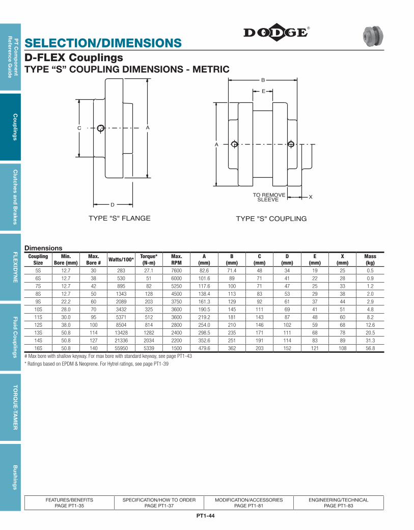
PT1-44
SELECTION/DIMENSIONS
PT
Co
mp
on
en
t R
efe
ren
ce G
uid
eC
ou
plin
gs
Clu
tch
es an
d B
rakesF
LE
XID
YN
EF
luid
Co
up
ling
sT
OR
QU
E-TA
ME
RB
ush
ing
s
FEATURES/BENEFITS PAGE PT1-35
SPECIFICATION/HOW TO ORDERPAGE PT1-37
MODIFICATION/ACCESSORIES PAGE PT1-81
ENGINEERING/TECHNICAL PAGE PT1-83
D-FLEX CouplingsTYPE “S” COUPLING DIMENSIONS - METRIC
D
AC
TYPE "S" FLANGE
SLEEVETO REMOVE X
E
B
A
TYPE "S" COUPLING
DimensionsCoupling
SizeMin.
Bore (mm)Max.
Bore # Watts/100* Torque* (N-m)
Max.RPM
A (mm)
B (mm)
C (mm)
D (mm)
E (mm)
X (mm)
Mass (kg)
5S 12.7 30 283 27.1 7600 82.6 71.4 48 34 19 25 0.5
6S 12.7 38 530 51 6000 101.6 89 71 41 22 28 0.9
7S 12.7 42 895 82 5250 117.6 100 71 47 25 33 1.2
8S 12.7 50 1343 128 4500 138.4 113 83 53 29 38 2.0
9S 22.2 60 2089 203 3750 161.3 129 92 61 37 44 2.9
10S 28.0 70 3432 325 3600 190.5 145 111 69 41 51 4.8
11S 30.0 95 5371 512 3600 219.2 181 143 87 48 60 8.2
12S 38.0 100 8504 814 2800 254.0 210 146 102 59 68 12.6
13S 50.8 114 13428 1282 2400 298.5 235 171 111 68 78 20.5
14S 50.8 127 21336 2034 2200 352.6 251 191 114 83 89 31.3
16S 50.8 140 55950 5339 1500 479.6 362 203 152 121 108 56.8
# Max bore with shallow keyway. For max bore with standard keyway, see page PT1-43
* Ratings based on EPDM & Neoprene. For Hytrel ratings, see page PT1-39
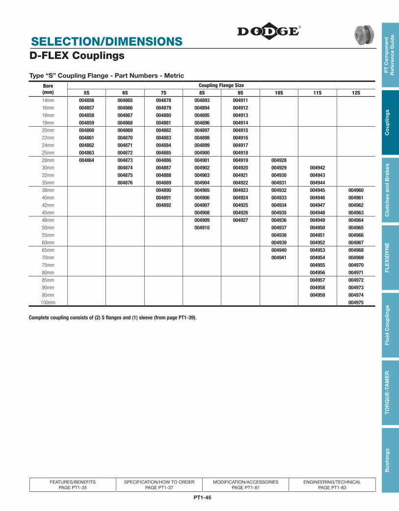
PT1-45
PT
Co
mp
on
en
t R
efe
ren
ce
Gu
ide
Co
up
ling
sC
lutc
hes
an
d B
rake
sF
LE
XID
YN
EF
luid
Co
up
ling
sT
OR
QU
E-T
AM
ER
Bu
shin
gs
SELECTION/DIMENSIONS
FEATURES/BENEFITS PAGE PT1-35
SPECIFICATION/HOW TO ORDERPAGE PT1-37
MODIFICATION/ACCESSORIES PAGE PT1-81
ENGINEERING/TECHNICAL PAGE PT1-83
D-FLEX Couplings
Type “S” Coupling Flange - Part Numbers - Metric
Bore (mm)
Coupling Flange Size5S 6S 7S 8S 9S 10S 11S 12S
14mm 004856 004865 004878 004893 00491116mm 004857 004866 004879 004894 00491218mm 004858 004867 004880 004895 00491319mm 004859 004868 004881 004896 00491420mm 004860 004869 004882 004897 00491522mm 004861 004870 004883 004898 00491624mm 004862 004871 004884 004899 00491725mm 004863 004872 004885 004900 00491828mm 004864 004873 004886 004901 004919 00492830mm 004874 004887 004902 004920 004929 00494232mm 004875 004888 004903 004921 004930 00494335mm 004876 004889 004904 004922 004931 00494438mm 004890 004905 004923 004932 004945 00496040mm 004891 004906 004924 004933 004946 00496142mm 004892 004907 004925 004934 004947 00496245mm 004908 004926 004935 004948 00496348mm 004909 004927 004936 004949 00496450mm 004910 004937 004950 00496555mm 004938 004951 00496660mm 004939 004952 00496765mm 004940 004953 00496870mm 004941 004954 00496975mm 004955 00497080mm 004956 00497185mm 004957 00497290mm 004958 00497395mm 004959 004974
100mm 004975
Complete coupling consists of (2) S flanges and (1) sleeve (from page PT1-39).
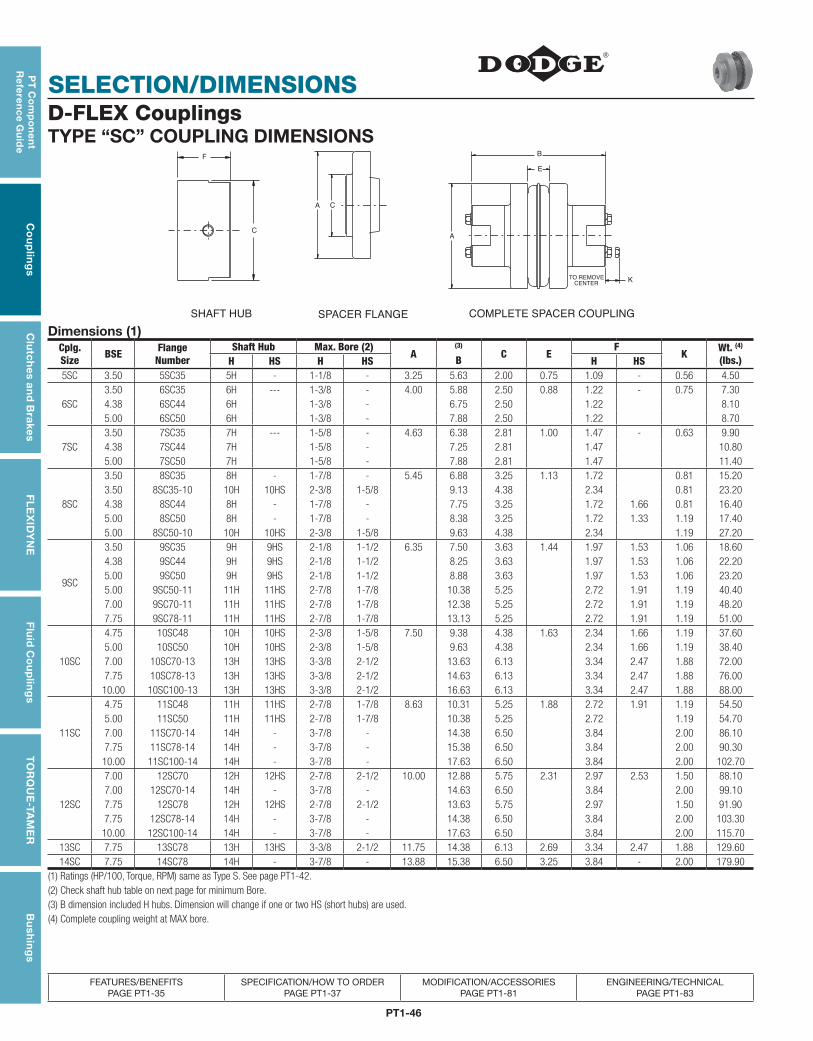
PT1-46
SELECTION/DIMENSIONS
PT
Co
mp
on
en
t R
efe
ren
ce G
uid
eC
ou
plin
gs
Clu
tch
es an
d B
rakesF
LE
XID
YN
EF
luid
Co
up
ling
sT
OR
QU
E-TA
ME
RB
ush
ing
s
FEATURES/BENEFITS PAGE PT1-35
SPECIFICATION/HOW TO ORDERPAGE PT1-37
MODIFICATION/ACCESSORIES PAGE PT1-81
ENGINEERING/TECHNICAL PAGE PT1-83
D-FLEX CouplingsTYPE “SC” COUPLING DIMENSIONS
F
C
SHAFT HUB
CA
SPACER FLANGE
CENTERTO REMOVE K
E
B
A
COMPLETE SPACER COUPLINGDimensions (1)
Cplg. Size BSE Flange
NumberShaft Hub Max. Bore (2)
A(3)
B C EF
K Wt. (4) (lbs.)H HS H HS H HS
5SC 3.50 5SC35 5H - 1-1/8 - 3.25 5.63 2.00 0.75 1.09 - 0.56 4.50
6SC3.50 6SC35 6H --- 1-3/8 - 4.00 5.88 2.50 0.88 1.22 - 0.75 7.304.38 6SC44 6H 1-3/8 - 6.75 2.50 1.22 8.105.00 6SC50 6H 1-3/8 - 7.88 2.50 1.22 8.70
7SC3.50 7SC35 7H --- 1-5/8 - 4.63 6.38 2.81 1.00 1.47 - 0.63 9.904.38 7SC44 7H 1-5/8 - 7.25 2.81 1.47 10.805.00 7SC50 7H 1-5/8 - 7.88 2.81 1.47 11.40
8SC
3.50 8SC35 8H - 1-7/8 - 5.45 6.88 3.25 1.13 1.72 0.81 15.203.50 8SC35-10 10H 10HS 2-3/8 1-5/8 9.13 4.38 2.34 0.81 23.204.38 8SC44 8H - 1-7/8 - 7.75 3.25 1.72 1.66 0.81 16.405.00 8SC50 8H - 1-7/8 - 8.38 3.25 1.72 1.33 1.19 17.405.00 8SC50-10 10H 10HS 2-3/8 1-5/8 9.63 4.38 2.34 1.19 27.20
9SC
3.50 9SC35 9H 9HS 2-1/8 1-1/2 6.35 7.50 3.63 1.44 1.97 1.53 1.06 18.604.38 9SC44 9H 9HS 2-1/8 1-1/2 8.25 3.63 1.97 1.53 1.06 22.205.00 9SC50 9H 9HS 2-1/8 1-1/2 8.88 3.63 1.97 1.53 1.06 23.205.00 9SC50-11 11H 11HS 2-7/8 1-7/8 10.38 5.25 2.72 1.91 1.19 40.407.00 9SC70-11 11H 11HS 2-7/8 1-7/8 12.38 5.25 2.72 1.91 1.19 48.207.75 9SC78-11 11H 11HS 2-7/8 1-7/8 13.13 5.25 2.72 1.91 1.19 51.00
10SC
4.75 10SC48 10H 10HS 2-3/8 1-5/8 7.50 9.38 4.38 1.63 2.34 1.66 1.19 37.605.00 10SC50 10H 10HS 2-3/8 1-5/8 9.63 4.38 2.34 1.66 1.19 38.407.00 10SC70-13 13H 13HS 3-3/8 2-1/2 13.63 6.13 3.34 2.47 1.88 72.007.75 10SC78-13 13H 13HS 3-3/8 2-1/2 14.63 6.13 3.34 2.47 1.88 76.0010.00 10SC100-13 13H 13HS 3-3/8 2-1/2 16.63 6.13 3.34 2.47 1.88 88.00
11SC
4.75 11SC48 11H 11HS 2-7/8 1-7/8 8.63 10.31 5.25 1.88 2.72 1.91 1.19 54.505.00 11SC50 11H 11HS 2-7/8 1-7/8 10.38 5.25 2.72 1.19 54.707.00 11SC70-14 14H - 3-7/8 - 14.38 6.50 3.84 2.00 86.107.75 11SC78-14 14H - 3-7/8 - 15.38 6.50 3.84 2.00 90.3010.00 11SC100-14 14H - 3-7/8 - 17.63 6.50 3.84 2.00 102.70
12SC
7.00 12SC70 12H 12HS 2-7/8 2-1/2 10.00 12.88 5.75 2.31 2.97 2.53 1.50 88.107.00 12SC70-14 14H - 3-7/8 - 14.63 6.50 3.84 2.00 99.107.75 12SC78 12H 12HS 2-7/8 2-1/2 13.63 5.75 2.97 1.50 91.907.75 12SC78-14 14H - 3-7/8 - 14.38 6.50 3.84 2.00 103.3010.00 12SC100-14 14H - 3-7/8 - 17.63 6.50 3.84 2.00 115.70
13SC 7.75 13SC78 13H 13HS 3-3/8 2-1/2 11.75 14.38 6.13 2.69 3.34 2.47 1.88 129.6014SC 7.75 14SC78 14H - 3-7/8 - 13.88 15.38 6.50 3.25 3.84 - 2.00 179.90
(1) Ratings (HP/100, Torque, RPM) same as Type S. See page PT1-42.(2) Check shaft hub table on next page for minimum Bore.(3) B dimension included H hubs. Dimension will change if one or two HS (short hubs) are used.(4) Complete coupling weight at MAX bore.
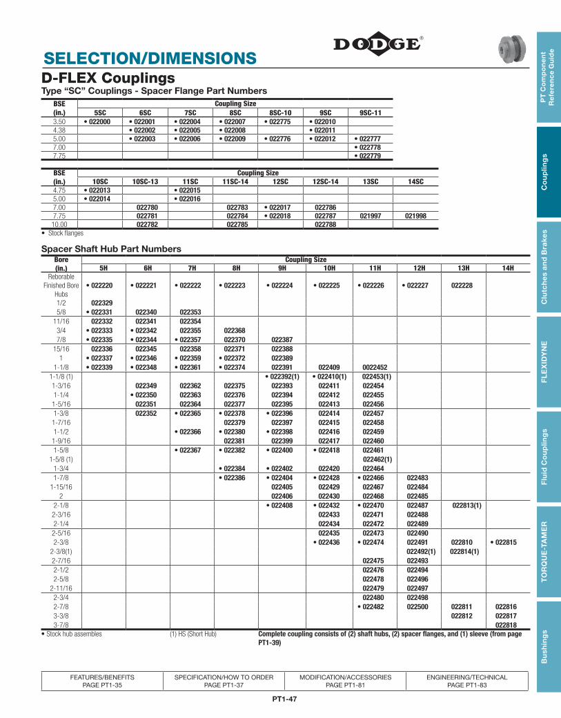
PT1-47
PT
Co
mp
on
en
t R
efe
ren
ce
Gu
ide
Co
up
ling
sC
lutc
hes
an
d B
rake
sF
LE
XID
YN
EF
luid
Co
up
ling
sT
OR
QU
E-T
AM
ER
Bu
shin
gs
SELECTION/DIMENSIONS
FEATURES/BENEFITS PAGE PT1-35
SPECIFICATION/HOW TO ORDERPAGE PT1-37
MODIFICATION/ACCESSORIES PAGE PT1-81
ENGINEERING/TECHNICAL PAGE PT1-83
D-FLEX CouplingsType “SC” Couplings - Spacer Flange Part Numbers
BSE(in.)
Coupling Size5SC 6SC 7SC 8SC 8SC-10 9SC 9SC-11
3.50 • 022000 • 022001 • 022004 • 022007 • 022775 • 0220104.38 • 022002 • 022005 • 022008 • 0220115.00 • 022003 • 022006 • 022009 • 022776 • 022012 • 0227777.00 • 0227787.75 • 022779
BSE(in.)
Coupling Size10SC 10SC-13 11SC 11SC-14 12SC 12SC-14 13SC 14SC
4.75 • 022013 • 0220155.00 • 022014 • 0220167.00 022780 022783 • 022017 0227867.75 022781 022784 • 022018 022787 021997 02199810.00 022782 022785 022788
• Stock flanges
Spacer Shaft Hub Part NumbersBore(in.)
Coupling Size5H 6H 7H 8H 9H 10H 11H 12H 13H 14H
Reborable Finished Bore
Hubs• 022220 • 022221 • 022222 • 022223 • 022224 • 022225 • 022226 • 022227 022228
1/2 0223295/8 • 022331 022340 022353
11/16 022332 022341 0223543/4 • 022333 • 022342 022355 0223687/8 • 022335 • 022344 • 022357 022370 022387
15/16 022336 022345 022358 022371 0223881 • 022337 • 022346 • 022359 • 022372 022389
1-1/8 • 022339 • 022348 • 022361 • 022374 022391 022409 00224521-1/8 (1) • 022392(1) • 022410(1) 022453(1)1-3/16 022349 022362 022375 022393 022411 0224541-1/4 • 022350 022363 022376 022394 022412 022455
1-5/16 022351 022364 022377 022395 022413 0224561-3/8 022352 • 022365 • 022378 • 022396 022414 022457
1-7/16 022379 022397 022415 0224581-1/2 • 022366 • 022380 • 022398 022416 022459
1-9/16 022381 022399 022417 0224601-5/8 • 022367 • 022382 • 022400 • 022418 022461
1-5/8 (1) 022462(1)1-3/4 • 022384 • 022402 022420 0224641-7/8 • 022386 • 022404 • 022428 • 022466 022483
1-15/16 022405 022429 022467 0224842 022406 022430 022468 022485
2-1/8 • 022408 • 022432 • 022470 022487 022813(1)2-3/16 022433 022471 0224882-1/4 022434 022472 022489
2-5/16 022435 022473 0224902-3/8 • 022436 • 022474 022491 022810 • 022815
2-3/8(1) 022492(1) 022814(1)2-7/16 022475 0224932-1/2 022476 0224942-5/8 022478 022496
2-11/16 022479 0224972-3/4 022480 0224982-7/8 • 022482 022500 022811 0228163-3/8 022812 0228173-7/8 022818
• Stock hub assembles (1) HS (Short Hub) Complete coupling consists of (2) shaft hubs, (2) spacer flanges, and (1) sleeve (from page PT1-39)
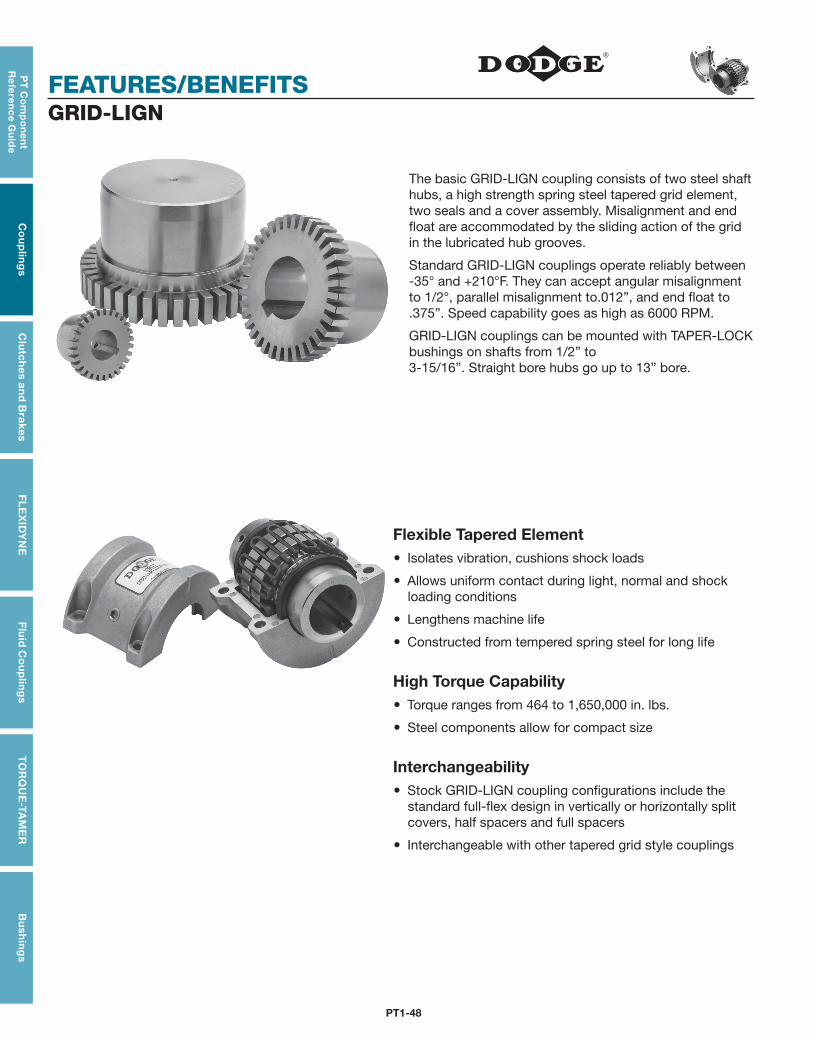
PT1-48
FEATURES/BENEFITS
PT
Co
mp
on
en
t R
efe
ren
ce G
uid
eC
ou
plin
gs
Clu
tch
es an
d B
rakesF
LE
XID
YN
EF
luid
Co
up
ling
sT
OR
QU
E-TA
ME
RB
ush
ing
s
GRID-LIGN
The basic GRID-LIGN coupling consists of two steel shaft hubs, a high strength spring steel tapered grid element, two seals and a cover assembly. Misalignment and end float are accommodated by the sliding action of the grid in the lubricated hub grooves.
Standard GRID-LIGN couplings operate reliably between -35° and +210°F. They can accept angular misalignment to 1/2°, parallel misalignment to.012”, and end float to .375”. Speed capability goes as high as 6000 RPM.
GRID-LIGN couplings can be mounted with TAPER-LOCK bushings on shafts from 1/2” to 3-15/16”. Straight bore hubs go up to 13” bore.
Flexible Tapered Element Isolates vibration, cushions shock loads
Allows uniform contact during light, normal and shock loading conditions
Lengthens machine life
Constructed from tempered spring steel for long life
High Torque Capability Torque ranges from 464 to 1,650,000 in. lbs.
Steel components allow for compact size
Interchangeability Stock GRID-LIGN coupling configurations include the
standard full-flex design in vertically or horizontally split covers, half spacers and full spacers
Interchangeable with other tapered grid style couplings

PT1-49
PT
Co
mp
on
en
t R
efe
ren
ce
Gu
ide
Co
up
ling
sC
lutc
hes
an
d B
rake
sF
LE
XID
YN
EF
luid
Co
up
ling
sT
OR
QU
E-T
AM
ER
Bu
shin
gs
FEATURES/BENEFITSGRID-LIGN
TAPERED GRID DESIGN Tapered grid element, combined with the contoured
hub grooves, transmit torque efficiency while accom-modating misalignment and cushioning shock loads
Grid element made from high strength steel that is quenched and tempered for long life
STYLE, SIZES AND RATINGS CHARTCoupling Styles Number
of SizesMaximum Ratings
Bore Torque SpeedT10 Standard Coupling H Cover 19 13.0” 1,650,000 6000
T20 Standard Coupling V Cover 10 5.0” 75,000 6000
T31 Full Spacer 8 4.25” 30,000 3600
T35 Half Spacer 8 4.25” 30,000 3600
PT1-50
SPECIFICATION/HOW TO ORDER/NOMENCLATURE
PT
Co
mp
on
en
t R
efe
ren
ce G
uid
eC
ou
plin
gs
Clu
tch
es an
d B
rakesF
LE
XID
YN
EF
luid
Co
up
ling
sT
OR
QU
E-TA
ME
RB
ush
ing
s
FEATURES/BENEFITS PAGE PT1-48
SELECTION/DIMENSIONS PAGE PT1-52
MODIFICATION/ACCESSORIES PAGE PT1-81
ENGINEERING/TECHNICAL PAGE PT1-83
GRID-LIGN
SPECIFICATIONGRID-LIGN Couplings are tapered grid style with hubs, grids and covers which are interchangeable with other industry standard tapered grid couplings. Grid hubs are machined steel, protected with an anti-rust coating. Hubs have optional methods of attachment to the shaft including but not limited to: clearance fit, interference fit or TAPER-LOCK bushings. Clearance fits and interference fits are supplied with an industry standard keyway. Clearance fits are supplied with two set screws, one over the key and one at 65°. The grid element is made of high strength spring steel, heat treated and shot peened to enhance strength and durability.
The coupling is designed and manufactured such that the grid member can be replaced without disturbing the connected equipment and without the requirement for realignment. All Grid-Lign Couplings are fitted with covers to retain lubrication and prevent the entry of abrasives and contaminants. Covers are of a two piece design to facilitate installation and are available as axial split or radial split. DODGE will provide recommendations for types and amounts of lubricant suitable for operation in ambient temperatures from -35°F to +210°F.
Spacer Couplings consist of two shaft hubs and a center assembly consisting of two spacer hubs, one grid and cover. The center assembly is readily removable to facilitate maintenance on pumps or other connected equipment. The center assembly must be replaceable without disturbing the coupled equipment and without realignment.
NOTE: Instruction manuals for all Dodge products available at www.dodge-pt.com
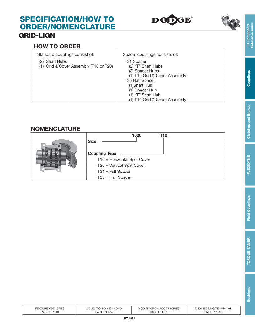
PT1-51
PT
Co
mp
on
en
t R
efe
ren
ce
Gu
ide
Co
up
ling
sC
lutc
hes
an
d B
rake
sF
LE
XID
YN
EF
luid
Co
up
ling
sT
OR
QU
E-T
AM
ER
Bu
shin
gs
SPECIFICATION/HOW TO ORDER/NOMENCLATURE
FEATURES/BENEFITS PAGE PT1-48
SELECTION/DIMENSIONS PAGE PT1-52
MODIFICATION/ACCESSORIES PAGE PT1-81
ENGINEERING/TECHNICAL PAGE PT1-83
GRID-LIGN
HOW TO ORDER Standard couplings consist of: Spacer couplings consists of:
(2) Shaft Hubs T31 Spacer (1) Grid & Cover Assembly (T10 or T20) (2) “T” Shaft Hubs
(2) Spacer Hubs (1) T10 Grid & Cover Assembly T35 Half Spacer (1)Shaft Hub (1) Spacer Hub (1) “T” Shaft Hub (1) T10 Grid & Cover Assembly
NOMENCLATURE 1020 T10 Size
Coupling Type T10 = Horizontal Split Cover T20 = Vertical Split Cover T31 = Full Spacer T35 = Half Spacer
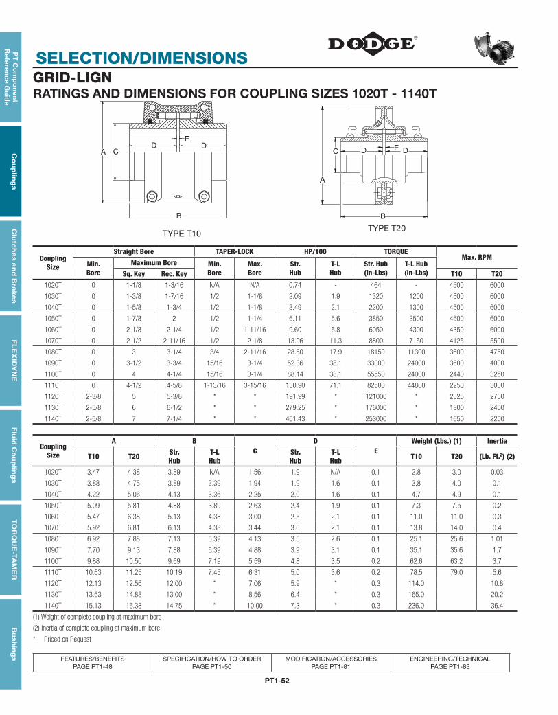
PT1-52
SELECTION/DIMENSIONS
PT
Co
mp
on
en
t R
efe
ren
ce G
uid
eC
ou
plin
gs
Clu
tch
es an
d B
rakesF
LE
XID
YN
EF
luid
Co
up
ling
sT
OR
QU
E-TA
ME
RB
ush
ing
s
FEATURES/BENEFITS PAGE PT1-48
SPECIFICATION/HOW TO ORDER PAGE PT1-50
MODIFICATION/ACCESSORIES PAGE PT1-81
ENGINEERING/TECHNICAL PAGE PT1-83
GRID-LIGNRATINGS AND DIMENSIONS FOR COUPLING SIZES 1020T - 1140T
D DA C
B
E
TYPE T10
B
A
C D E D
TYPE T20
CouplingSize
Straight Bore TAPER-LOCK HP/100 TORQUEMax. RPM
Min.Bore
Maximum Bore Min.Bore
Max.Bore
Str.Hub
T-LHub
Str. Hub(In-Lbs)
T-L Hub(In-Lbs)Sq. Key Rec. Key T10 T20
1020T 0 1-1/8 1-3/16 N/A N/A 0.74 - 464 - 4500 6000
1030T 0 1-3/8 1-7/16 1/2 1-1/8 2.09 1.9 1320 1200 4500 6000
1040T 0 1-5/8 1-3/4 1/2 1-1/8 3.49 2.1 2200 1300 4500 6000
1050T 0 1-7/8 2 1/2 1-1/4 6.11 5.6 3850 3500 4500 6000
1060T 0 2-1/8 2-1/4 1/2 1-11/16 9.60 6.8 6050 4300 4350 6000
1070T 0 2-1/2 2-11/16 1/2 2-1/8 13.96 11.3 8800 7150 4125 5500
1080T 0 3 3-1/4 3/4 2-11/16 28.80 17.9 18150 11300 3600 4750
1090T 0 3-1/2 3-3/4 15/16 3-1/4 52.36 38.1 33000 24000 3600 4000
1100T 0 4 4-1/4 15/16 3-1/4 88.14 38.1 55550 24000 2440 3250
1110T 0 4-1/2 4-5/8 1-13/16 3-15/16 130.90 71.1 82500 44800 2250 3000
1120T 2-3/8 5 5-3/8 * * 191.99 * 121000 * 2025 2700
1130T 2-5/8 6 6-1/2 * * 279.25 * 176000 * 1800 2400
1140T 2-5/8 7 7-1/4 * * 401.43 * 253000 * 1650 2200
CouplingSize
A BC
DE
Weight (Lbs.) (1) Inertia
T10 T20 Str.Hub
T-LHub
Str.Hub
T-LHub T10 T20 (Lb. Ft.2) (2)
1020T 3.47 4.38 3.89 N/A 1.56 1.9 N/A 0.1 2.8 3.0 0.03
1030T 3.88 4.75 3.89 3.39 1.94 1.9 1.6 0.1 3.8 4.0 0.1
1040T 4.22 5.06 4.13 3.36 2.25 2.0 1.6 0.1 4.7 4.9 0.1
1050T 5.09 5.81 4.88 3.89 2.63 2.4 1.9 0.1 7.3 7.5 0.2
1060T 5.47 6.38 5.13 4.38 3.00 2.5 2.1 0.1 11.0 11.0 0.3
1070T 5.92 6.81 6.13 4.38 3.44 3.0 2.1 0.1 13.8 14.0 0.4
1080T 6.92 7.88 7.13 5.39 4.13 3.5 2.6 0.1 25.1 25.6 1.01
1090T 7.70 9.13 7.88 6.39 4.88 3.9 3.1 0.1 35.1 35.6 1.7
1100T 9.88 10.50 9.69 7.19 5.59 4.8 3.5 0.2 62.6 63.2 3.7
1110T 10.63 11.25 10.19 7.45 6.31 5.0 3.6 0.2 78.5 79.0 5.6
1120T 12.13 12.56 12.00 * 7.06 5.9 * 0.3 114.0 10.8
1130T 13.63 14.88 13.00 * 8.56 6.4 * 0.3 165.0 20.2
1140T 15.13 16.38 14.75 * 10.00 7.3 * 0.3 236.0 36.4
(1) Weight of complete coupling at maximum bore
(2) Inertia of complete coupling at maximum bore
* Priced on Request
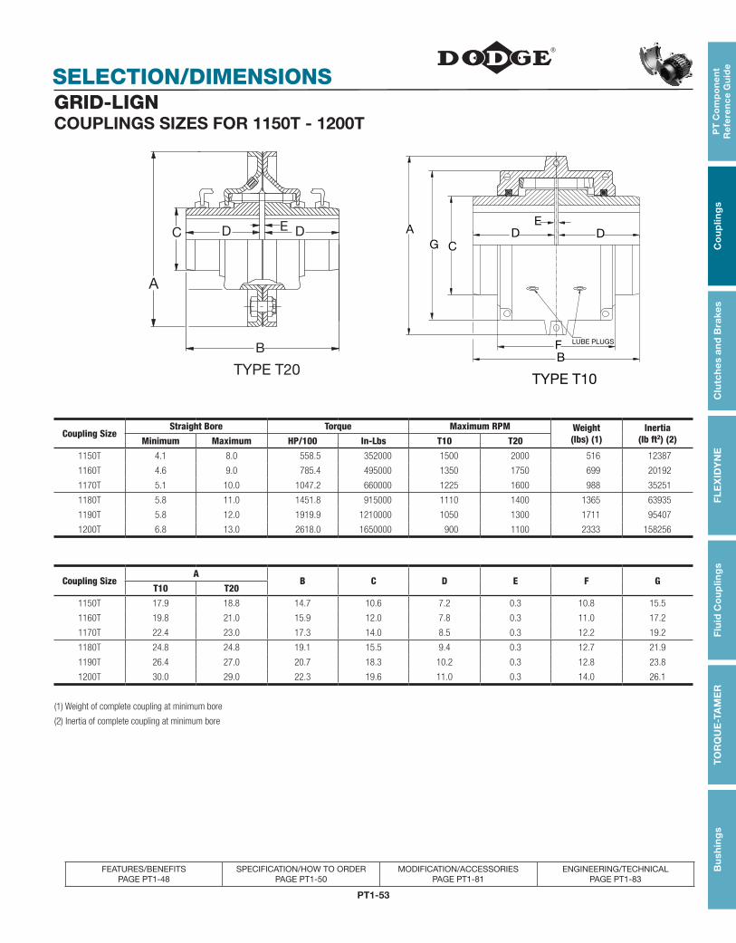
PT1-53
PT
Co
mp
on
en
t R
efe
ren
ce
Gu
ide
Co
up
ling
sC
lutc
hes
an
d B
rake
sF
LE
XID
YN
EF
luid
Co
up
ling
sT
OR
QU
E-T
AM
ER
Bu
shin
gs
FEATURES/BENEFITS PAGE PT1-48
SPECIFICATION/HOW TO ORDER PAGE PT1-50
MODIFICATION/ACCESSORIES PAGE PT1-81
ENGINEERING/TECHNICAL PAGE PT1-83
SELECTION/DIMENSIONSGRID-LIGNCOUPLINGS SIZES FOR 1150T - 1200T
Coupling Size Straight Bore Torque Maximum RPM Weight
(lbs) (1)Inertia
(lb ft2) (2)Minimum Maximum HP/100 In-Lbs T10 T20
1150T 4.1 8.0 558.5 352000 1500 2000 516 12387
1160T 4.6 9.0 785.4 495000 1350 1750 699 20192
1170T 5.1 10.0 1047.2 660000 1225 1600 988 35251
1180T 5.8 11.0 1451.8 915000 1110 1400 1365 63935
1190T 5.8 12.0 1919.9 1210000 1050 1300 1711 95407
1200T 6.8 13.0 2618.0 1650000 900 1100 2333 158256
Coupling Size A
B C D E F GT10 T20
1150T 17.9 18.8 14.7 10.6 7.2 0.3 10.8 15.5
1160T 19.8 21.0 15.9 12.0 7.8 0.3 11.0 17.2
1170T 22.4 23.0 17.3 14.0 8.5 0.3 12.2 19.2
1180T 24.8 24.8 19.1 15.5 9.4 0.3 12.7 21.9
1190T 26.4 27.0 20.7 18.3 10.2 0.3 12.8 23.8
1200T 30.0 29.0 22.3 19.6 11.0 0.3 14.0 26.1
(1) Weight of complete coupling at minimum bore
(2) Inertia of complete coupling at minimum bore
B
A
C D E D
TYPE T20
D
BF
E
LUBE PLUGS
AG C
D
TYPE T10
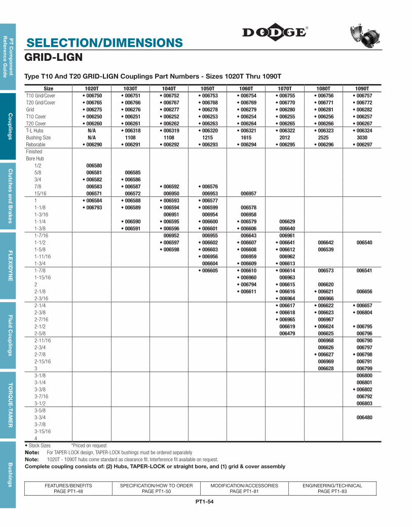
PT1-54
SELECTION/DIMENSIONS
PT
Co
mp
on
en
t R
efe
ren
ce G
uid
eC
ou
plin
gs
Clu
tch
es an
d B
rakesF
LE
XID
YN
EF
luid
Co
up
ling
sT
OR
QU
E-TA
ME
RB
ush
ing
s
FEATURES/BENEFITS PAGE PT1-48
SPECIFICATION/HOW TO ORDER PAGE PT1-50
MODIFICATION/ACCESSORIES PAGE PT1-81
ENGINEERING/TECHNICAL PAGE PT1-83
GRID-LIGN
Type T10 And T20 GRID-LIGN Couplings Part Numbers - Sizes 1020T Thru 1090T
Size 1020T 1030T 1040T 1050T 1060T 1070T 1080T 1090TT10 Grid/Cover • 006750 • 006751 • 006752 • 006753 • 006754 • 006755 • 006756 • 006757T20 Grid/Cover • 006765 • 006766 • 006767 • 006768 • 006769 • 006770 • 006771 • 006772Grid • 006275 • 006276 • 006277 • 006278 • 006279 • 006280 • 006281 • 006282T10 Cover • 006250 • 006251 • 006252 • 006253 • 006254 • 006255 • 006256 • 006257T20 Cover • 006260 • 006261 • 006262 • 006263 • 006264 • 006265 • 006266 • 006267T-L Hubs N/A • 006318 • 006319 • 006320 • 006321 • 006322 • 006323 • 006324Bushing Size N/A 1108 1108 1215 1615 2012 2525 3030Reborable • 006290 • 006291 • 006292 • 006293 • 006294 • 006295 • 006296 • 006297FinishedBore Hub
1/2 0065805/8 006581 0065853/4 • 006582 • 0065867/8 006583 • 006587 • 006592 • 00657615/16 006571 006572 006950 006953 0069571 • 006584 • 006588 • 006593 • 0065771-1/8 • 006793 • 006589 • 006594 • 006599 0065781-3/16 006951 006954 0069581-1/4 • 006590 • 006595 • 006600 • 006579 0066291-3/8 • 006591 • 006596 • 006601 • 006606 0066401-7/16 006952 006955 006643 0069611-1/2 • 006597 • 006602 • 006607 • 006641 006642 0065401-5/8 • 006598 • 006603 • 006608 • 006612 0065391-11/16 • 006956 006959 0069621-3/4 006604 • 006609 • 0066131-7/8 • 006605 • 006610 • 006614 006573 0065411-15/16 • 006960 0069632 • 006794 • 006615 0066202-1/8 • 006611 • 006616 • 006621 0066562-3/16 • 006964 0069662-1/4 • 006617 • 006622 • 0066572-3/8 • 006618 • 006623 • 0068042-7/16 • 006965 0069672-1/2 006619 • 006624 • 0067952-5/8 006479 006625 0067962-11/16 006968 0067902-3/4 006626 0067972-7/8 • 006627 • 0067982-15/16 006969 0067913 006628 0067993-1/8 0068003-1/4 0068013-3/8 • 0068023-7/16 0067923-1/2 0068033-5/83-3/4 0064803-7/83-15/164
• Stock Sizes *Priced on requestNote: For TAPER-LOCK design, TAPER-LOCK bushings must be ordered separatelyNote: 1020T - 1090T hubs come standard as clearance fit. Interference fit available on request.Complete coupling consists of: (2) Hubs, TAPER-LOCK or straight bore, and (1) grid & cover assembly
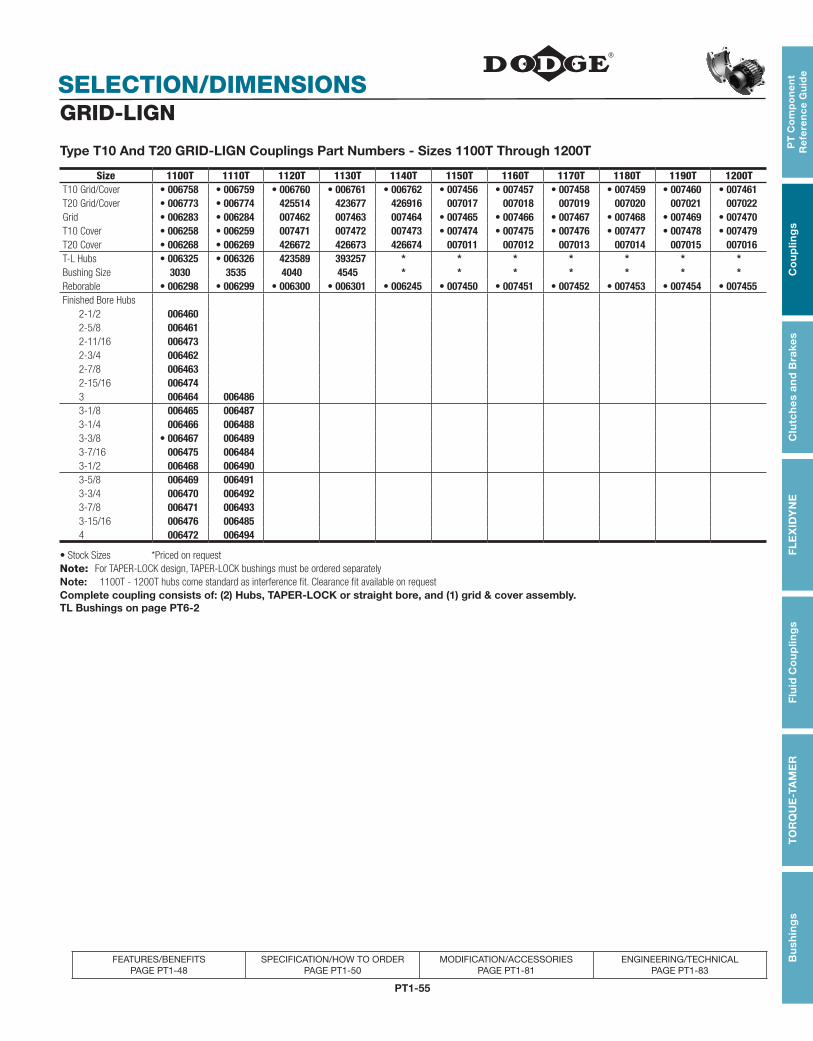
PT1-55
PT
Co
mp
on
en
t R
efe
ren
ce
Gu
ide
Co
up
ling
sC
lutc
hes
an
d B
rake
sF
LE
XID
YN
EF
luid
Co
up
ling
sT
OR
QU
E-T
AM
ER
Bu
shin
gs
FEATURES/BENEFITS PAGE PT1-48
SPECIFICATION/HOW TO ORDER PAGE PT1-50
MODIFICATION/ACCESSORIES PAGE PT1-81
ENGINEERING/TECHNICAL PAGE PT1-83
SELECTION/DIMENSIONS
Size 1100T 1110T 1120T 1130T 1140T 1150T 1160T 1170T 1180T 1190T 1200TT10 Grid/Cover • 006758 • 006759 • 006760 • 006761 • 006762 • 007456 • 007457 • 007458 • 007459 • 007460 • 007461T20 Grid/Cover • 006773 • 006774 425514 423677 426916 007017 007018 007019 007020 007021 007022Grid • 006283 • 006284 007462 007463 007464 • 007465 • 007466 • 007467 • 007468 • 007469 • 007470T10 Cover • 006258 • 006259 007471 007472 007473 • 007474 • 007475 • 007476 • 007477 • 007478 • 007479T20 Cover • 006268 • 006269 426672 426673 426674 007011 007012 007013 007014 007015 007016T-L Hubs • 006325 • 006326 423589 393257 * * * * * * *Bushing Size 3030 3535 4040 4545 * * * * * * *Reborable • 006298 • 006299 • 006300 • 006301 • 006245 • 007450 • 007451 • 007452 • 007453 • 007454 • 007455Finished Bore Hubs
2-1/2 0064602-5/8 0064612-11/16 0064732-3/4 0064622-7/8 0064632-15/16 0064743 006464 0064863-1/8 006465 0064873-1/4 006466 0064883-3/8 • 006467 0064893-7/16 006475 0064843-1/2 006468 0064903-5/8 006469 0064913-3/4 006470 0064923-7/8 006471 0064933-15/16 006476 0064854 006472 006494
GRID-LIGN
Type T10 And T20 GRID-LIGN Couplings Part Numbers - Sizes 1100T Through 1200T
• Stock Sizes *Priced on requestNote: For TAPER-LOCK design, TAPER-LOCK bushings must be ordered separatelyNote: 1100T - 1200T hubs come standard as interference fit. Clearance fit available on requestComplete coupling consists of: (2) Hubs, TAPER-LOCK or straight bore, and (1) grid & cover assembly.TL Bushings on page PT6-2
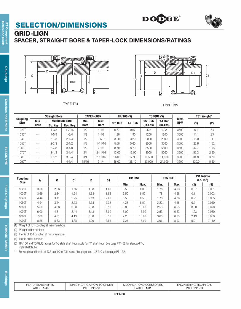
PT1-56
SELECTION/DIMENSIONS
PT
Co
mp
on
en
t R
efe
ren
ce G
uid
eC
ou
plin
gs
Clu
tch
es an
d B
rakesF
LE
XID
YN
EF
luid
Co
up
ling
sT
OR
QU
E-TA
ME
RB
ush
ing
s
FEATURES/BENEFITS PAGE PT1-48
SPECIFICATION/HOW TO ORDER PAGE PT1-50
MODIFICATION/ACCESSORIES PAGE PT1-81
ENGINEERING/TECHNICAL PAGE PT1-83
GRID-LIGNSPACER, STRAIGHT BORE & TAPER-LOCK DIMENSIONS/RATINGS
CA
D D
TYPE T31
A
C1C
D1BSE
D
TYPE T35
BSE
Coupling Size
Straight Bore TAPER-LOCK HP/100 (5) TORQUE (5)Max.RPM
T31 Weight*
Min.Bore
Maximum Bore Min. Bore
Max.Bore Str. Hub T-L Hub Str. Hub
(In-Lbs)T-L Hub(In-Lbs) (1) (2)
Sq. Key Rec. Key1020T --- 1-3/8 1-7/16 1/2 1-1/8 0.67 0.67 422 422 3600 8.1 .54
1030T --- 1-5/8 1-3/4 1/2 1-1/8 1.90 1.90 1200 1200 3600 11.1 .83
1040T --- 2-1/8 2-1/4 1/2 1-7/16 3.20 3.20 2000 2000 3600 18.0 1.11
1050T --- 2-3/8 2-1/2 1/2 1-11/16 5.60 5.60 3500 3500 3600 26.6 1.52
1060T --- 2-7/8 3-1/8 1/2 2-1/8 8.70 8.70 5500 5500 3600 42.7 1.98
1070T --- 3-1/8 3-1/4 3/4 2-11/16 13.00 13.00 8000 8000 3600 52.3 2.60
1080T --- 3-1/2 3-3/4 3/4 2-11/16 26.00 17.90 16,500 11,300 3600 84.8 3.70
1090T --- 4 4-1/4 15/16 3-1/4 48.00 38.10 30,000 24,000 3600 130.0 5.20
CouplingSize A C C1 D D1
T31 BSE T35 BSE T31 Inertia(Lb. Ft.2)
Min. Max. Min. Max. (3) (4)1020T 3.38 2.06 1.56 1.38 1.88 3.50 8.00 1.78 4.03 0.07 0.001
1030T 3.69 2.34 1.94 1.63 1.88 3.50 8.50 1.78 4.28 0.11 0.003
1040T 4.44 3.11 2.25 2.13 2.00 3.50 8.50 1.78 4.28 0.21 0.005
1050T 4.94 3.44 2.63 2.38 2.38 4.38 8.50 2.22 4.28 0.51 0.010
1060T 5.69 4.06 3.00 2.88 3.50 5.00 13.00 2.53 6.53 0.88 0.020
1070T 6.00 4.31 3.44 3.13 3.00 5.00 13.00 2.53 6.53 1.23 0.030
1080T 7.00 4.81 4.13 3.50 3.50 7.25 16.00 3.66 8.03 2.49 0.060
1090T 8.25 5.63 4.88 4.00 3.88 7.25 16.00 3.66 8.03 5.01 0.110
(1) Weight of T31 coupling at maximum bore
(2) Weight adder per inch
(3) Inertia of T31 coupling at maximum bore
(4) Inertia adder per inch
(5) HP/100 and TORQUE ratings for T-L style shaft hubs apply for “T” shaft hubs. See page PT1-52 for standard T-L style shaft hubs
* For weight and inertia of T35 use 1/2 of T31 value (this page) and 1/2 T10 value (page PT1-52)
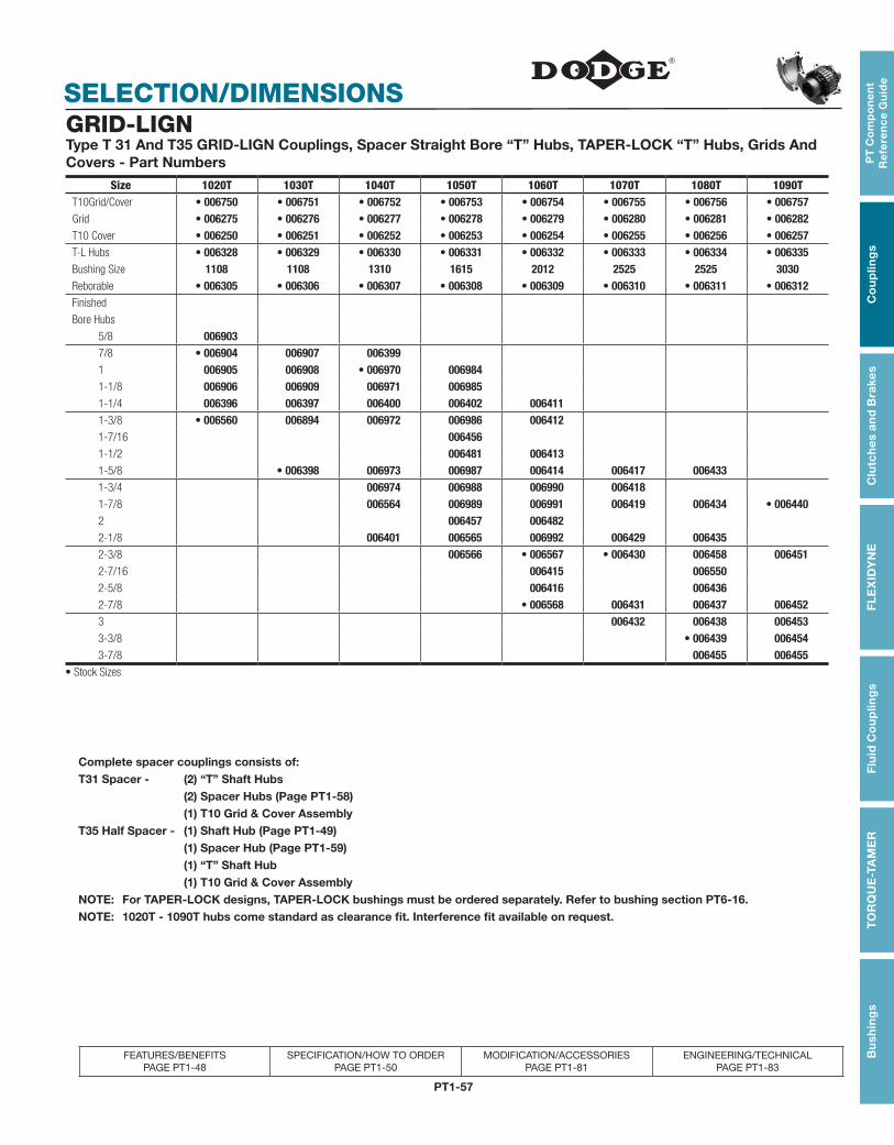
PT1-57
PT
Co
mp
on
en
t R
efe
ren
ce
Gu
ide
Co
up
ling
sC
lutc
hes
an
d B
rake
sF
LE
XID
YN
EF
luid
Co
up
ling
sT
OR
QU
E-T
AM
ER
Bu
shin
gs
FEATURES/BENEFITS PAGE PT1-48
SPECIFICATION/HOW TO ORDER PAGE PT1-50
MODIFICATION/ACCESSORIES PAGE PT1-81
ENGINEERING/TECHNICAL PAGE PT1-83
SELECTION/DIMENSIONSGRID-LIGNType T 31 And T35 GRID-LIGN Couplings, Spacer Straight Bore “T” Hubs, TAPER-LOCK “T” Hubs, Grids And Covers - Part Numbers
Size 1020T 1030T 1040T 1050T 1060T 1070T 1080T 1090TT10Grid/Cover • 006750 • 006751 • 006752 • 006753 • 006754 • 006755 • 006756 • 006757Grid • 006275 • 006276 • 006277 • 006278 • 006279 • 006280 • 006281 • 006282T10 Cover • 006250 • 006251 • 006252 • 006253 • 006254 • 006255 • 006256 • 006257T-L Hubs • 006328 • 006329 • 006330 • 006331 • 006332 • 006333 • 006334 • 006335Bushing Size 1108 1108 1310 1615 2012 2525 2525 3030Reborable • 006305 • 006306 • 006307 • 006308 • 006309 • 006310 • 006311 • 006312Finished
Bore Hubs
5/8 0069037/8 • 006904 006907 0063991 006905 006908 • 006970 0069841-1/8 006906 006909 006971 0069851-1/4 006396 006397 006400 006402 0064111-3/8 • 006560 006894 006972 006986 006412 1-7/16 0064561-1/2 006481 0064131-5/8 • 006398 006973 006987 006414 006417 0064331-3/4 006974 006988 006990 0064181-7/8 006564 006989 006991 006419 006434 • 0064402 006457 0064822-1/8 006401 006565 006992 006429 0064352-3/8 006566 • 006567 • 006430 006458 006451 2-7/16 006415 0065502-5/8 006416 0064362-7/8 • 006568 006431 006437 0064523 006432 006438 0064533-3/8 • 006439 0064543-7/8 006455 006455
• Stock Sizes
Complete spacer couplings consists of:T31 Spacer - (2) “T” Shaft Hubs (2) Spacer Hubs (Page PT1-58) (1) T10 Grid & Cover AssemblyT35 Half Spacer - (1) Shaft Hub (Page PT1-49) (1) Spacer Hub (Page PT1-59) (1) “T” Shaft Hub (1) T10 Grid & Cover AssemblyNOTE: For TAPER-LOCK designs, TAPER-LOCK bushings must be ordered separately. Refer to bushing section PT6-16.NOTE: 1020T - 1090T hubs come standard as clearance fit. Interference fit available on request.
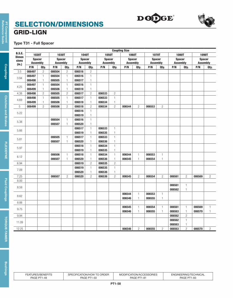
PT1-58
SELECTION/DIMENSIONS
PT
Co
mp
on
en
t R
efe
ren
ce G
uid
eC
ou
plin
gs
Clu
tch
es an
d B
rakesF
LE
XID
YN
EF
luid
Co
up
ling
sT
OR
QU
E-TA
ME
RB
ush
ing
s
FEATURES/BENEFITS PAGE PT1-48
SPECIFICATION/HOW TO ORDER PAGE PT1-50
MODIFICATION/ACCESSORIES PAGE PT1-81
ENGINEERING/TECHNICAL PAGE PT1-83
GRID-LIGN
Type T31 - Full Spacer
B.S.E. Dimen sions (in.)
Coupling Size1020T 1030T 1040T 1050T 1060T 1070T 1080T 1090TSpacer
AssemblySpacer
AssemblySpacer
AssemblySpacer
AssemblySpacer
AssemblySpacer
AssemblySpacer
AssemblySpacer
AssemblyP/N Qty. P/N Qty. P/N Qty. P/N Qty. P/N Qty. P/N Qty. P/N Qty. P/N Qty.
3.5 006497 2 006504 2 006516 2
3.94006497 1 006504 1 006516 1
006498 1 006505 1 006517 1
4.25006497 1 006504 1 006516 1
006499 1 006506 1 006518 1
4.38 006498 2 006505 2 006517 2 006533 2
4.69006498 1 006505 1 006517 1 006533 1
006499 1 006506 1 006518 1 006534 1
5 006499 2 006506 2 006518 2 006534 2 006544 2 006553 2
5.22006516 1
006519 1
5.38006504 1 006516 1
006507 1 006520 1
5.66006517 1 006533 1
006519 1 006535 1
5.81006505 1 006517 1 006533 1
006507 1 006520 1 006536 1
5.97006518 1 006534 1
006519 1 006535 1
6.12006506 1 006518 1 006534 1 006544 1 006553 1
006507 1 006520 1 006536 1 006545 1 006554 1
6.94 006519 2 006535 2
7.09006519 1 006535 1
006520 1 006536 1
7.25 006507 2 006520 2 006536 2 006545 2 006554 2 006561 2 006569 2
8.00
8.59006561 1
006562 1
8.62006544 1 006553 1
006546 1 006555 1
8.88
9.75006545 1 006554 1 006561 1 006569 1
006546 1 006555 1 006563 1 006570 1
9.94 006562 2
11.09006562 1
006563 1
12.25 006546 2 006555 2 006563 2 006570 2
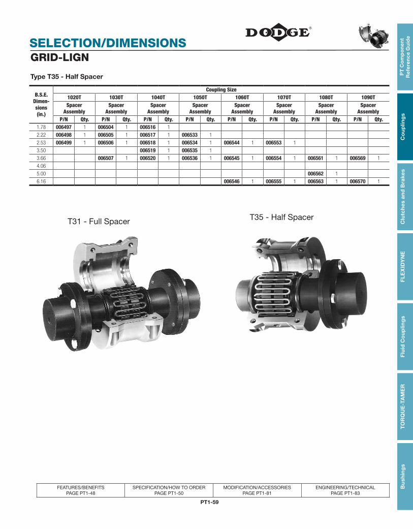
PT1-59
PT
Co
mp
on
en
t R
efe
ren
ce
Gu
ide
Co
up
ling
sC
lutc
hes
an
d B
rake
sF
LE
XID
YN
EF
luid
Co
up
ling
sT
OR
QU
E-T
AM
ER
Bu
shin
gs
FEATURES/BENEFITS PAGE PT1-48
SPECIFICATION/HOW TO ORDER PAGE PT1-50
MODIFICATION/ACCESSORIES PAGE PT1-81
ENGINEERING/TECHNICAL PAGE PT1-83
SELECTION/DIMENSIONSGRID-LIGN
Type T35 - Half Spacer
B.S.E. Dimen- sions(in.)
Coupling Size1020T 1030T 1040T 1050T 1060T 1070T 1080T 1090TSpacer
AssemblySpacer
AssemblySpacer
AssemblySpacer
AssemblySpacer
AssemblySpacer
AssemblySpacer
AssemblySpacer
AssemblyP/N Qty. P/N Qty. P/N Qty. P/N Qty. P/N Qty. P/N Qty. P/N Qty. P/N Qty.
1.78 006497 1 006504 1 006516 1
2.22 006498 1 006505 1 006517 1 006533 1
2.53 006499 1 006506 1 006518 1 006534 1 006544 1 006553 1
3.50 006519 1 006535 1
3.66 006507 1 006520 1 006536 1 006545 1 006554 1 006561 1 006569 1
4.06
5.00 006562 1
6.16 006546 1 006555 1 006563 1 006570 1
T31 - Full Spacer T35 - Half Spacer

PT1-60
FEATURES/BENEFITS
PT
Co
mp
on
en
t R
efe
ren
ce G
uid
eC
ou
plin
gs
Clu
tch
es an
d B
rakesF
LE
XID
YN
EF
luid
Co
up
ling
sT
OR
QU
E-TA
ME
RB
ush
ing
s
Gear CouplingsThe Power-Dense, High-Torque Gear Coupling
The DODGE Gear Coupling (DGF) offers unmatched performance and proven reliability
Quality Manufacturing High-quality steel
Larger tooth profile provides additional service factor
Good inherent balance
Proven O-ring seal design
Machined flanges and gasket for improved sealing
High-grade fasteners
Performance Benefits High torque rating allows for coupling downsizing
Versatile design permits interchangeable half couplings
Low backlash (well suited for reversing applications)
Crowned tooth profile for longer life and improved performance
DODGE Benefits Coupling solutions for any application
Choose from DODGE coupling family: Gear (DGF), PARA-FLEX, GRID-LIGN, D-FLEX, Rigid and Fluid - all available from stock
Combine DODGE couplings with any DODGE speed reducer for unmatched performance
Choose from thousands of combinations to get a package tailored to meet your needs
Years of application expertise
DODGE engineers can help specify products to achieve maximum results from your equipment
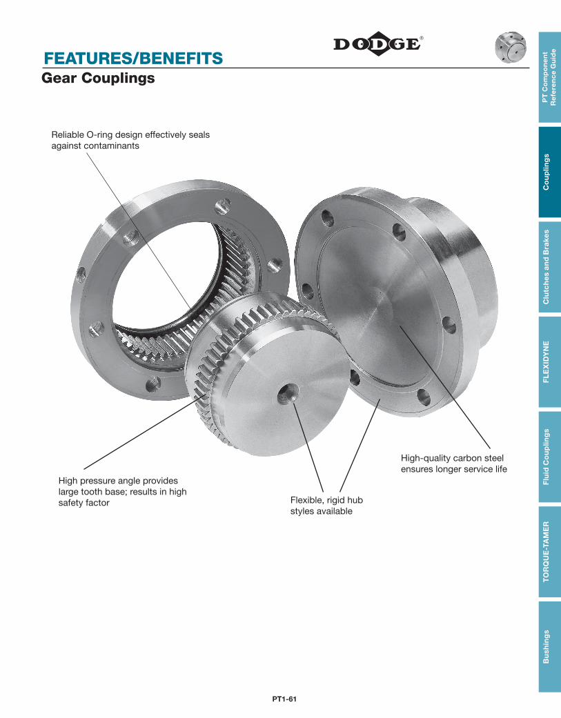
PT1-61
PT
Co
mp
on
en
t R
efe
ren
ce
Gu
ide
Co
up
ling
sC
lutc
hes
an
d B
rake
sF
LE
XID
YN
EF
luid
Co
up
ling
sT
OR
QU
E-T
AM
ER
Bu
shin
gs
FEATURES/BENEFITSGear Couplings
Reliable O-ring design effectively seals against contaminants
High pressure angle provides large tooth base; results in high safety factor Flexible, rigid hub
styles available
High-quality carbon steel ensures longer service life
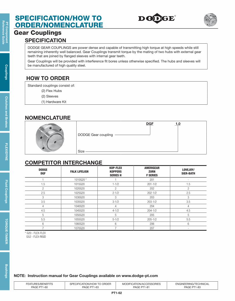
PT1-62
SPECIFICATION/HOW TO ORDER/NOMENCLATURE
PT
Co
mp
on
en
t R
efe
ren
ce G
uid
eC
ou
plin
gs
Clu
tch
es an
d B
rakesF
LE
XID
YN
EF
luid
Co
up
ling
sT
OR
QU
E-TA
ME
RB
ush
ing
s
FEATURES/BENEFITS PAGE PT1-60
SPECIFICATION/HOW TO ORDER PAGE PT1-63
MODIFICATION/ACCESSORIES PAGE PT1-81
ENGINEERING/TECHNICAL PAGE PT1-83
Gear CouplingsSPECIFICATION
DODGE GEAR COUPLINGS are power dense and capable of transmitting high torque at high speeds while still remaining inherently well balanced. Gear Couplings transmit torque by the mating of two hubs with external gear teeth that are joined by flanged sleeves with internal gear teeth.
Gear Couplings will be provided with interference fit bores unless otherwise specified. The hubs and sleeves will be manufactured of high quality steel.
HOW TO ORDERStandard couplings consist of:
(2) Flex Hubs
(2) Sleeves
(1) Hardware Kit
NOMENCLATURE DGF 1.0
DODGE Gear coupling
Size
COMPETITOR INTERCHANGEDODGE
DGF FALK LIFELIGNKOP-FLEXKOPPERSSERIES H
AMERIGEARZURN
F SERIES
LOVEJOY/SIER-BATH
1 1010G20 * 1 201 -
1.5 1015G20 1-1/2 201-1/2 1.5
2 1020G20 2 202 2
2.5 1025G20 2-1/2 202-1/2 2.5
3 1030G20 3 203 3
3.5 1035G20 3-1/2 203-1/2 3.5
4 1040G20 4 204 4
4.5 1045G20 4-1/2 204-1/2 4.5
5 1050G20 5 205 5
5.5 1055G20 5-1/2 205-1/2 5.5
6 1060G20 6 206 6
7 1070G20 7 207 -
* G20 - FLEX-FLEX G52 - FLEX-RIGID
NOTE: Instruction manual for Gear Couplings available on www.dodge-pt.com
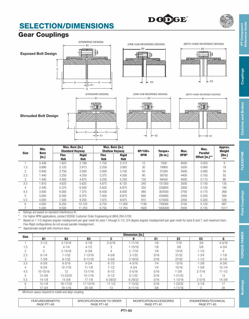
PT1-63
PT
Co
mp
on
en
t R
efe
ren
ce
Gu
ide
Co
up
ling
sC
lutc
hes
an
d B
rake
sF
LE
XID
YN
EF
luid
Co
up
ling
sT
OR
QU
E-T
AM
ER
Bu
shin
gs
SELECTION/DIMENSIONS
FEATURES/BENEFITS PAGE PT1-60
SPECIFICATION/HOW TO ORDER PAGE PT1-62
MODIFICATION/ACCESSORIES PAGE PT1-81
ENGINEERING/TECHNICAL PAGE PT1-83
Gear Couplings(ONE HUB REVERSED DESIGN) (BOTH HUBS REVERSED DESIGN)
B2
E2 E3
B3
(STANDRAD DESIGN)B1
C
D DE1
G
SizeMin. Bore[in.]
Max. Bore [in.]Standard Keyway
Max. Bore [in.]Shallow Keyway HP/100+
RPMTorque+[lb-in.]
Max.RPM*
Max.Parallel
Offset [in.]**
Approx.Weight[lbs.]***
Flex Hub
Rigid Hub
Flex Hub
Rigid Hub
1 0.438 1.625 2.188 1.750 2.313 12 7500 6000 0.055 91.5 0.690 2.125 2.813 2.250 3.063 30 18900 5500 0.060 192 0.940 2.750 3.500 3.000 3.750 50 31500 5000 0.085 34
2.5 1.440 3.250 4.250 3.375 4.500 90 56700 4400 0.105 553 1.440 4.000 4.875 4.250 5.250 150 94500 4000 0.115 86
3.5 1.810 4.625 5.625 4.875 6.125 240 151300 3500 0.130 1354 2.440 5.375 6.500 5.625 6.875 350 220600 3000 0.150 195
4.5 3.000 6.000 7.375 6.438 8.000 480 302500 2700 0.175 2685 3.000 6.500 8.375 7.000 8.875 690 434900 2500 0.200 394
5.5 4.000 7.500 9.250 7.875 9.875 910 573500 2200 0.220 5266 4.000 8.250 10.125 8.750 11.000 1190 750000 2100 0.120 6877 5.000 9.500 11.250 9.750 12.250 1600 1008400 2000 0.135 1017
+ Ratings are based on standard interference fit.* For higher RPM applications, contact DODGE Customer Order Engineering at (864) 284-5700.** Based on 1-1/2 degrees angular misalignment per gear mesh for sizes 1 through 5-1/2, 3/4 degree angular misalignment per gear mesh for sizes 6 and 7, and maximum bore. Flex-Rigid configurations do not accept parallel misalignment.*** Approximate weight with minimum bore.
D D
E1
G
B1
C
E2
B2
E3
B3
(STANDARD DESIGN) (ONE HUB REVERSED DESIGN) (BOTH HUBS REVERSED DESIGN)
Exposed Bolt Design
Shrouded Bolt Design
SizeDimension [in.]
B1 B2 B3 C D E1 E2 E3 G1 3-1/2 3-13/16 4-1/8 2-5/16 1-11/16 1/8 7/16 3/4 4-3/16
1.5 4 4-1/4 4-1/2 3 1-15/16 1/8 3/8 5/8 4-3/4 2 5 5-13/16 6-3/8 4 2 -7/16 1/8 13/16 1-1/2 6
2.5 6-1/4 7-1/32 7-13/16 4-5/8 3-1/32 3/16 31/32 1-3/4 7-1/8 3 7-3/8 8-1/32 8-11/16 5-5/8 3-19/32 3/16 27/32 1-1/2 8-1/8
3.5 8-5/8 9-3/16 9-3/4 6-1/2 4-3/16 1/4 13/16 1-3/8 9-3/8 4 9-3/4 10-7/16 11-1/8 7-1/2 4-3/4 1/4 15/16 1-5/8 10-1/4
4.5 10-15/16 12 13-1/16 8-1/2 5-5/16 5/16 1-3/8 2-7/16 11-1/2 5 12-3/8 13-23/32 15-1/16 9-1/2 6-1/32 5/16 1-21/32 3 13
5.5 14-1/8 15-5/8 17-1/8 6-29/32 6-29/32 5/16 1-13/16 3-5/16 14-3/8 6 15-1/8 16-17/32 17-15/16 11-1/2 7-13/32 5/16 1-23/32 3-1/8 17 7 17-3/4 19-1/16 20-3/8 13 8-11/16 3/8 1-11/16 3 20
* Minimum space required to install and align coupling.

PT1-64
PT
Co
mp
on
en
t R
efe
ren
ce G
uid
eC
ou
plin
gs
Clu
tch
es an
d B
rakesF
LE
XID
YN
EF
luid
Co
up
ling
sT
OR
QU
E-TA
ME
RB
ush
ing
s
FEATURES/BENEFITS PAGE PT1-60
SPECIFICATION/HOW TO ORDER PAGE PT1-62
MODIFICATION/ACCESSORIES PAGE PT1-81
ENGINEERING/TECHNICAL PAGE PT1-83
SELECTION/DIMENSIONSGear Couplings
J
AB.C.
F
T
U
H
I
(FLANGED SLEEVE AND RIGID HUB DETAILS)
Part NumbersPart Number Description Part Number Description Part Number Description
Size 1.0 Size 3.0 Size 5.0013110 DGF 1.0 FLEX HUB 013126 DGF 3.0 FLEX HUB 013142 DGF 5.0 FLEX HUB013111 DGF 1.0 SLEEVE EB 013127 DGF 3.0 SLEEVE EB 013143 DGF 5.0 SLEEVE EB012975 DGF 1.0 SLEEVE SB 012979 DGF 3.0 SLEEVE SB 012983 DGF 5.0 SLEEVE SB013112 DGF 1.0 RIGID HUB EB 013128 DGF 3.0 RIGID HUB EB 013144 DGF 5.0 RIGID HUB EB013113 DGF 1.0 EB HARDWARE KIT 013129 DGF 3.0 EB HARDWARE KIT 013145 DGF 5.0 EB HARDWARE KIT394171 DGF 1.0 SB HARDWARE KIT 394175 DGF 3.0 SB HARDWARE KIT 394179 DGF 5.0 SB HARDWARE KIT
Size 1.5 Size 3.5 Size 5.5013114 DGF 1.5 FLEX HUB 013130 DGF 3.5 FLEX HUB 013146 DGF 5.5 FLEX HUB013115 DGF 1.5 SLEEVE EB 013131 DGF 3.5 SLEEVE EB 013147 DGF 5.5 SLEEVE EB012976 DGF 1.5 SLEEVE SB 012980 DGF 3.5 SLEEVE SB 012984 DGF 5.5 SLEEVE SB013116 DGF 1.5 RIGID HUB EB 013132 DGF 3.5 RIGID HUB EB 013148 DGF 5.5 RIGID HUB EB013117 DGF 1.5 EB HARDWARE KIT 013133 DGF 3.5 EB HARDWARE KIT 013149 DGF 5.5 EB HARDWARE KIT394172 DGF 1.5 SB HARDWARE KIT 394176 DGF 3.5 SB HARDWARE KIT 394180 DGF 5.5 SB HARDWARE KIT
Size 2.0 Size 4.0 Size 6.0013118 DGF 2.0 FLEX HUB 013134 DGF 4.0 FLEX HUB 013150 DGF 6.0 FLEX HUB013119 DGF 2.0 SLEEVE EB 013135 DGF 4.0 SLEEVE EB 013151 DGF 6.0 SLEEVE EB012977 DGF 2.0 SLEEVE SB 012981 DGF 4.0 SLEEVE SB 013152 DGF 6.0 RIGID HUB EB013120 DGF 2.0 RIGID HUB EB 013136 DGF 4.0 RIGID HUB EB 013153 DGF 6.0 HARDWARE KIT013121 DGF 2.0 EB HARDWARE KIT 013137 DGF 4.0 EB HARDWARE KIT394173 DGF 2.0 SB HARDWARE KIT 394177 DGF 4.0 SB HARDWARE KIT
Size 2.5 Size 4.5 Size 7.0013122 DGF 2.5 FLEX HUB 013138 DGF 4.5 FLEX HUB 013154 DGF 7.0 FLEX HUB013123 DGF 2.5 SLEEVE EB 013139 DGF 4.5 SLEEVE EB 013155 DGF 7.0 SLEEVE EB012978 DGF 2.5 SLEEVE SB 012982 DGF 4.5 SLEEVE SB 013156 DGF 7.0 RIGID HUB EB013124 DGF 2.5 RIGID HUB EB 013140 DGF 4.5 RIGID HUB EB 013157 DGF 7.0 HARDWARE KIT013125 DGF 2.5 EB HARDWARE KIT 013141 DGF 4.5 EB HARDWARE KIT394174 DGF 2.5 SB HARDWARE KIT 394178 DGF 4.5 SB HARDWARE KIT
Ordering Information: Standard Gear Couplings may be orders in 3 different assemblies - 1. Flex-Flex (or Full Flex): To order a complete Flex-Flex coupling you need - (2) Flex Hubs [reborable], (2) Sleeves (includes Seal), and (1) Hardware Kit.2. Flex-Rigid: To order a complete Flex-Rigid Coupling you need - (1) Flex Hub [reborable], (1) Sleeve (includes Seal), (1) Rigid Hub [reborable], and (1) Hardware Kit.3. Rigid-Rigid: To order a complete Rigid-Rigid Coupling you need - (2) Rigid Hubs [reborable], and (1) Hardware Kit.
T
U (HOLE SIZE)
S
HB.C.
F
A
T1
Size
Outside Flange Flange Thickness Hub Undercut Undercut Hole Bolt Numberof
BoltsDiameter
AWidth
J T T1 DiameterF
DepthI
DiameterH
DiameterU
CircleB.C.
All Dimensions in Inches1 EB 4-9/16 1-21/32 9/16 - 3 3/32 2 -7/8 1/4 3-3/4 61 SB 4-9/16 1-21/32 9/16 1/2 3 3/32 2 -7/8 1/4 3-3/4 6
1.5 EB 6 1-7/8 3/4 - 3-7/8 3/32 3-11/16 3/8 4-13/16 81.5 SB 6 1-7/8 3/4 1/2 3-7/8 3/32 3-11/16 3/8 4-13/16 82 EB 7 2-3/8 3/4 - 4-13/16 3/32 4-5/8 1/2 5 -7/8 62 SB 7 2-3/8 3/4 1/2 4-13/16 3/32 4-5/8 3/8 5-13/16 10
2.5 EB 8-3/8 2-7/8 15/16 - 5-13/16 3/32 5-7/16 5/8 7-1/8 62.5 SB 8-3/8 2-7/8 15/16 5/16 5-13/16 3/32 5-7/16 1/2 7 103 EB 9-7/16 3-5/16 15/16 - 6-13/16 3/32 6-7/16 5/8 8-1/8 83 SB 9-7/16 3-5/16 15/16 5/16 6-13/16 3/32 6-7/16 1/2 8 12
3.5 EB 11 3-13/16 1-1/8 - 7-27/32 3/32 7-3/8 3/4 9-1/2 83.5 SB 11 3-13/16 1-1/8 3/8 7-27/32 3/32 7-3/8 5/8 9-9/32 124 EB 12-1/2 4-1/4 1-1/8 - 9-3/16 3/16 8-3/4 3/4 11 84 SB 12-1/2 4-1/4 1-1/8 3/8 9-3/16 3/16 8-3/4 5/8 10-5/8 14
4.5 EB 13-5/8 4-13/16 1-1/8 - 10-5/16 3/16 9-3/4 3/4 12 104.5 SB 13-5/8 4-13/16 1-1/8 3/8 10-5/16 3/16 9-3/4 5/8 11-3/4 145 EB 15-5/16 5-1/2 1-1/2 - 11-7/16 3/16 10-3/4 7/8 13-1/2 85 SB 15-5/16 5-1/2 1-1/2 9/16 11-7/16 3/16 10-3/4 3/8 13-3/16 14
5.5 EB 16-3/4 6 1-1/2 - 10-1/2 3/16 12-1/8 7/8 14-1/2 145.5 SB 16-3/4 6 1-1/2 9/16 10-1/2 3/16 12-1/8 3/4 14-7/16 166 EB* 18 6-11/16 1 - 13-15/16 3/16 13 -3/8 7/8 15-3/4 147 EB* 20-3/4 7-3/8 1-1/8 - 15-3/4 1/4 14-5/8 1 18-1/4 16
EB = Exposed Bolt PatternSB = Shrouded Bolt Pattern* Sizes 6 & 7 only available in exposed bolt pattern
Exposed Bolt
Design
Shrouded Bolt Design
PT1-65
PT
Co
mp
on
en
t R
efe
ren
ce
Gu
ide
Co
up
ling
sC
lutc
hes
an
d B
rake
sF
LE
XID
YN
EF
luid
Co
up
ling
sT
OR
QU
E-T
AM
ER
Bu
shin
g
NEW PRODUCT
FEATURES/BENEFITS PAGE PT1-61
SPECIFICATION/HOW TO ORDER PAGE PT1-67
MODIFICATION/ACCESSORIES PAGE PT1-78
ENGINEERING/TECHNICAL PAGE PT1-80
DODGE Moment Couplings
DODGE Moment Couplings are specifically designed to make the rigid connection between the output shaft of a gearbox and an overhung driven load, commonly a head pulley. Highly engineered to meet the most rigorous application requirements, these couplings are capable of handling both the required application torque and the bending moment forces of the suspended weight of a drive package, including the gearbox, motor, high-speed coupling, and swing base.
Moment Coupling hubs are designed to maximize the bore range of the driver and driven shafts. The male and female hubs are manufactured from 4140 alloy steel and are assembled with Grade 8 bolts. Suitable for a wide range of applications, DODGE Moment Couplings span a torque range of 100,000 to 920,000 inch-pounds and may be used in DODGE MagnaGear packages and in other operations.
Information needed from the customer for DODGE engineering to select the appropriate Moment Coupling for an application:
Horse Power / Torque / Speed Requirements
Driver and Driven Shaft Sizes
Overhung Load
Length of Lever Arm
Application Specifics: Type of Operation; Required Stops and Starts; Shock Loads and Vibration
For more information on Couplings contact your authorized DODGE distributor or log onto www.dodge-pt.com.
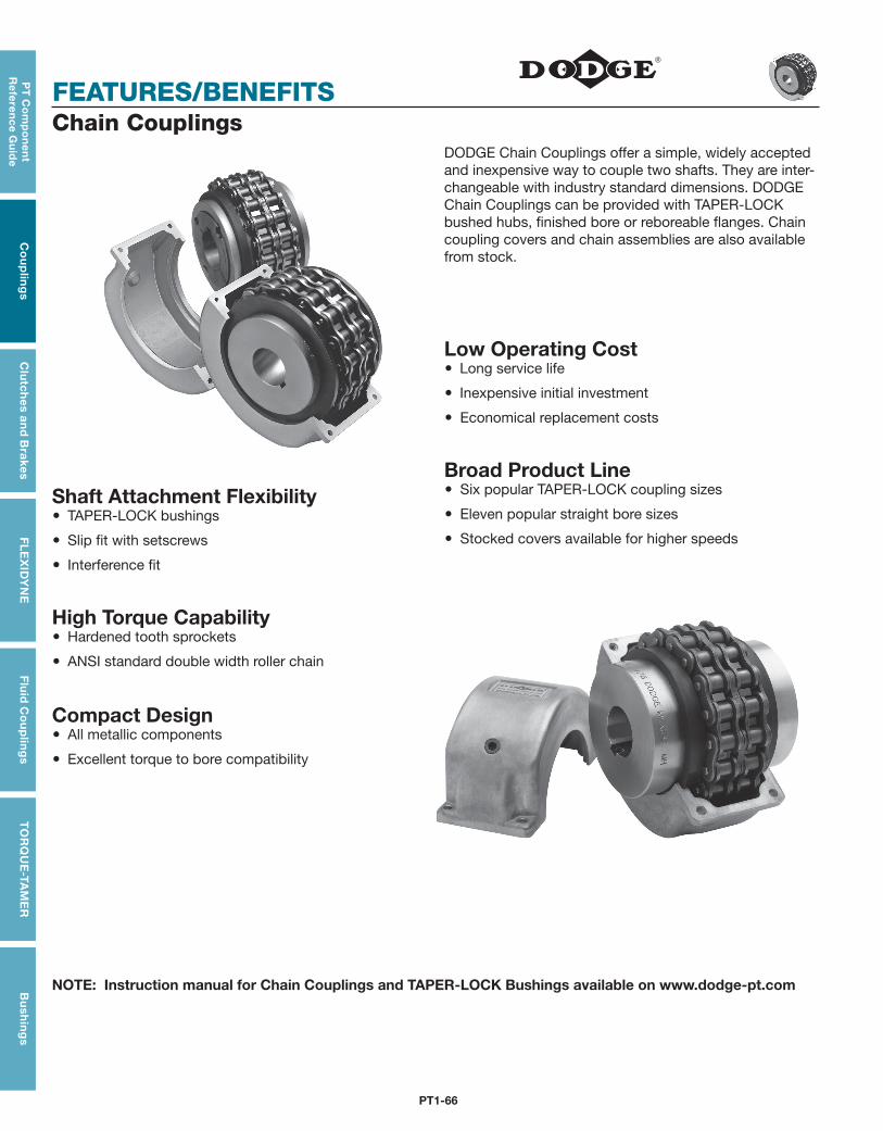
PT1-66
FEATURES/BENEFITS
PT
Co
mp
on
en
t R
efe
ren
ce G
uid
eC
ou
plin
gs
Clu
tch
es an
d B
rakesF
LE
XID
YN
EF
luid
Co
up
ling
sT
OR
QU
E-TA
ME
RB
ush
ing
s
Chain CouplingsDODGE Chain Couplings offer a simple, widely accepted and inexpensive way to couple two shafts. They are inter-changeable with industry standard dimensions. DODGE Chain Couplings can be provided with TAPER-LOCK bushed hubs, finished bore or reboreable flanges. Chain coupling covers and chain assemblies are also available from stock.
Shaft Attachment Flexibility TAPER-LOCK bushings
Slip fit with setscrews
Interference fit
High Torque Capability Hardened tooth sprockets
ANSI standard double width roller chain
Compact Design All metallic components
Excellent torque to bore compatibility
Low Operating Cost Long service life
Inexpensive initial investment
Economical replacement costs
Broad Product Line Six popular TAPER-LOCK coupling sizes
Eleven popular straight bore sizes
Stocked covers available for higher speeds
NOTE: Instruction manual for Chain Couplings and TAPER-LOCK Bushings available on www.dodge-pt.com
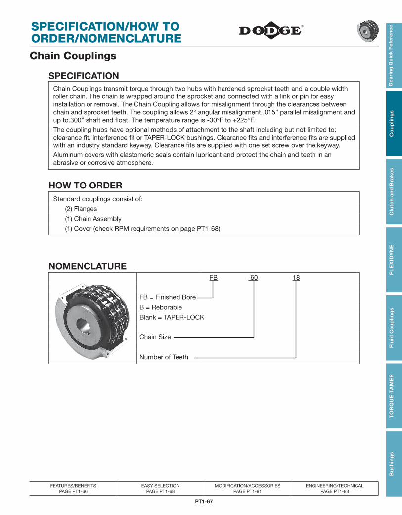
PT1-67
Gea
rin
g Q
uic
k R
efe
ren
ce
Co
up
ling
sC
lutc
h a
nd
Bra
kes
FL
EX
IDY
NE
Flu
id C
ou
plin
gs
TO
RQ
UE
-TA
ME
RB
ush
ing
s
FEATURES/BENEFITS PAGE PT1-66
EASY SELECTION PAGE PT1-68
MODIFICATION/ACCESSORIES PAGE PT1-81
ENGINEERING/TECHNICAL PAGE PT1-83
SPECIFICATION/HOW TO ORDER/NOMENCLATUREChain Couplings
SPECIFICATIONChain Couplings transmit torque through two hubs with hardened sprocket teeth and a double width roller chain. The chain is wrapped around the sprocket and connected with a link or pin for easy installation or removal. The Chain Coupling allows for misalignment through the clearances between chain and sprocket teeth. The coupling allows 2° angular misalignment,.015” parallel misalignment and up to.300” shaft end float. The temperature range is -30°F to +225°F.The coupling hubs have optional methods of attachment to the shaft including but not limited to: clearance fit, interference fit or TAPER-LOCK bushings. Clearance fits and interference fits are supplied with an industry standard keyway. Clearance fits are supplied with one set screw over the keyway.Aluminum covers with elastomeric seals contain lubricant and protect the chain and teeth in an abrasive or corrosive atmosphere.
HOW TO ORDERStandard couplings consist of:
(2) Flanges
(1) Chain Assembly
(1) Cover (check RPM requirements on page PT1-68)
NOMENCLATURE FB 60 18
FB = Finished Bore
B = Reborable
Blank = TAPER-LOCK
Chain Size
Number of Teeth
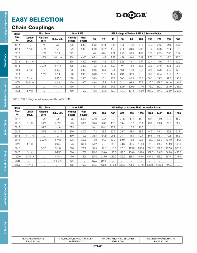
PT1-68
EASY SELECTION
Gea
ring
Qu
ick Re
fere
nc
eC
ou
plin
gs
Clu
tch
es an
d B
rakesF
LE
XID
YN
EF
luid
Co
up
ling
sT
OR
QU
E-TA
ME
RB
ush
ing
s
FEATURES/BENEFITS PAGE PT1-66
SPECIFICATION/HOW TO ORDER PAGE PT1-72
MODIFICATION/ACCESSORIES PAGE PT1-81
ENGINEERING/TECHNICAL PAGE PT1-83
Chain CouplingsBasicSizeNo.
Max. Bore Max. RPM *HP Ratings at Various RPM 1.0 Service Factor
TAPER- LOCK
FinishedBore Reborable Without
CoversWith
Covers 10 20 40 60 80 100 150 200 250 300
4012 . . 3/4 7/8 875 5000 0.22 0.43 0.86 1.29 1.72 2.15 2.83 3.43 4.03 4.57
4016 1-1/8 1-1/8 1-5/16 875 5000 0.38 0.77 1.53 2.30 3.06 3.83 5.02 6.06 7.14 8.08
5012 . . . 1-1/8 1-1/8 875 .. . 40 0.81 1.61 2.42 3.23 4.03 5.30 6.39 7.57 8.57
5016 . . . 1-5/8 1-11/16 800 4000 0.73 1.46 2.93 4.39 5.86 7.32 9.60 11.7 13.7 15.5
5018 1-11/16 . . . 2 800 4000 0.95 1.89 3.79 5.68 7.57 9.47 12.4 15.0 17.7 20.0
6018 . . . 2-7/16 2-7/16 675 3000 1.73 3.46 6.92 10.4 13.8 17.3 22.9 27.6 32.5 36.8
6020 2-1/8 . . . 2-3/4 675 3000 2.25 4.50 9.01 13.5 18.0 22.5 29.6 35.6 42.0 47.6
8018 . . . 2-7/8 3-1/8 500 2000 3.86 7.72 15.4 23.2 30.9 38.6 50.8 61.4 72.3 81.5
8020 3-1/4 . . . 3-9/16 500 2000 5.03 10.1 20.1 30.2 40.3 50.3 66.1 79.7 94.0 106.0
10020 3-15/16 . . . 4-5/8 450 1800 8.68 17.4 34.7 52.1 69.4 86.8 115.0 139.0 162.0 184.0
12018 . . . . . . 4-11/16 400 . . . 13.7 27.3 54.6 82.0 109.0 137.0 178.0 217.0 253.0 288.0
12020 4-7/16 . . . . . . 400 1600 16.8 33.6 67.2 101.0 134.0 168.0 218.0 264.0 308.0 350.0
* TAPER-LOCK Bushings are not recommended below 250 RPM
BasicSizeNo.
Max. Bore Max. RPM HP Ratings at Various RPM 1.0 Service Factor
TAPER- LOCK
FinishedBore Reborable Without
CoversWith
Covers 350 400 500 600 800 1000 1200 1400 160 1800
4012 . . 3/4 7/8 875 5000 5.10 5.57 6.55 7.56 9.42 11.3 13.1 14.9 16.6 18.2
4016 1-1/8 1-1/8 1-5/16 875 5000 9.04 9.89 11.6 13.4 16.7 20.1 23.0 26.3 29.3 32.7
5012 . . . 1-1/8 1-1/8 875 .. . 9.41 10.42 12.2 14.1 17.5 21.0 .. . . . . . . . . .
5016 . . . 1-5/8 1-11/16 800 4000 17.3 18.9 22.3 25.7 32.0 38.3 44.5 50.4 56.2 61.9
5018 1-11/16 . . . 2 800 4000 22.4 24.5 28.8 33.1 41.4 49.7 56.8 65.1 72.6 80.9
6018 . . . 2-7/16 2-7/16 675 3000 41.2 44.9 53.0 60.9 75.9 90.7 105.0 120.0 134.0 147.0
6020 2-1/8 . . . 2-3/4 675 3000 53.2 58.2 68.5 78.8 98.5 118.0 135.0 155.0 173.0 192.0
8018 . . . 2-7/8 3-1/8 500 2000 91.5 99.8 118.0 135.0 169.0 202.0 234.0 266.0 297.0 326.0
8020 3-1/4 . . . 3-9/16 500 2000 119.0 130.0 153.0 176.0 220.0 264.0 302.0 346.0 386.0 430.0
10020 3-15/16 . . . 4-5/8 450 1800 205.0 225.0 265.0 305.0 380.0 454.0 527.0 598.0 667.0 734.0
12018 . . . . . . 4-11/16 400 ... 322.0 355.0 ... ... ... ... ... ...
12020 4-7/16 . . . . . . 400 1600 391.0 432.0 510.0 585.0 708.0 877.0 1003.0 1135.0 1273.0 ....
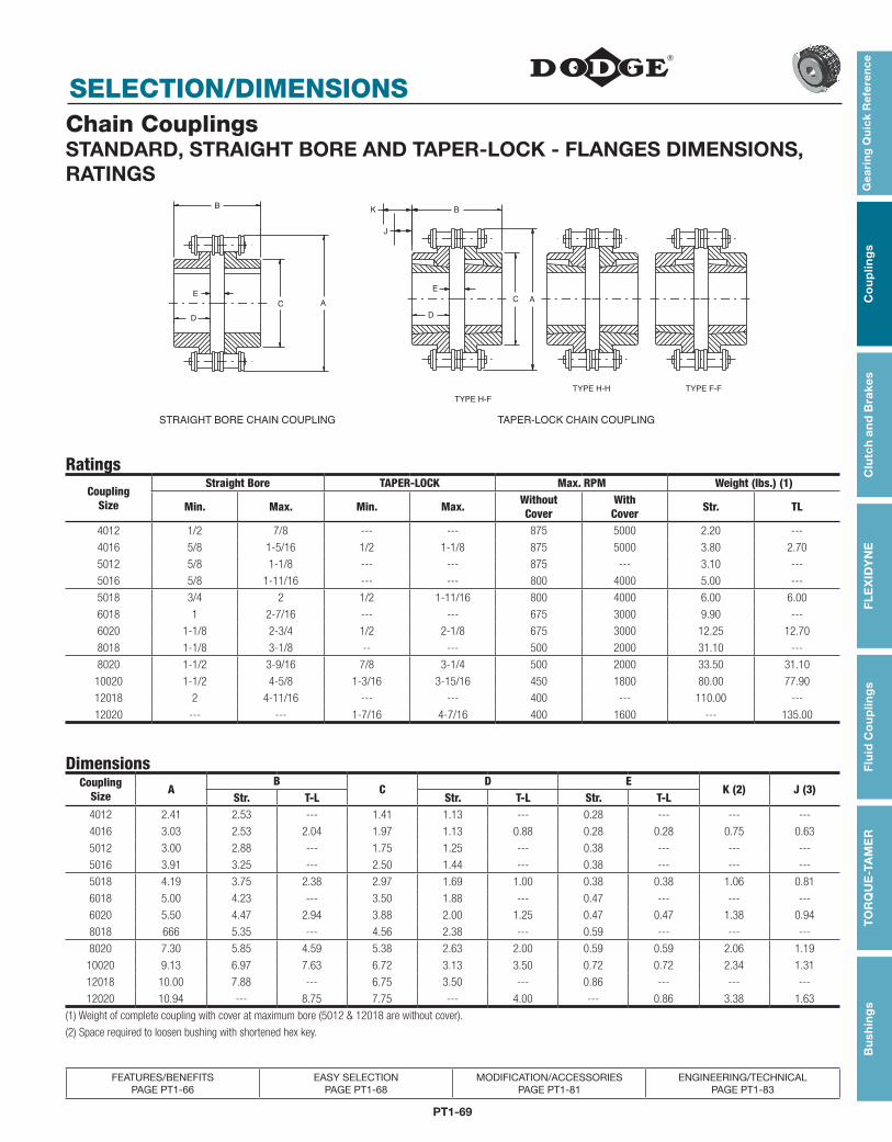
PT1-69
Gea
rin
g Q
uic
k R
efe
ren
ce
Co
up
ling
sC
lutc
h a
nd
Bra
kes
FL
EX
IDY
NE
Flu
id C
ou
plin
gs
TO
RQ
UE
-TA
ME
RB
ush
ing
s
FEATURES/BENEFITS PAGE PT1-66
EASY SELECTION PAGE PT1-68
MODIFICATION/ACCESSORIES PAGE PT1-81
ENGINEERING/TECHNICAL PAGE PT1-83
SELECTION/DIMENSIONSChain CouplingsSTANDARD, STRAIGHT BORE AND TAPER-LOCK - FLANGES DIMENSIONS, RATINGS
D
E
B
C A
STRAIGHT BORE CHAIN COUPLING
TYPE H-F
TYPE H-H TYPE F-F
TAPER-LOCK CHAIN COUPLING
K
J
D
C A
B
E
RatingsCoupling
Size
Straight Bore TAPER-LOCK Max. RPM Weight (lbs.) (1)
Min. Max. Min. Max. Without Cover
With Cover Str. TL
4012 1/2 7/8 --- --- 875 5000 2.20 ---
4016 5/8 1-5/16 1/2 1-1/8 875 5000 3.80 2.70
5012 5/8 1-1/8 --- --- 875 --- 3.10 ---
5016 5/8 1-11/16 --- --- 800 4000 5.00 ---
5018 3/4 2 1/2 1-11/16 800 4000 6.00 6.00
6018 1 2-7/16 --- --- 675 3000 9.90 ---
6020 1-1/8 2-3/4 1/2 2-1/8 675 3000 12.25 12.70
8018 1-1/8 3-1/8 -- --- 500 2000 31.10 ---
8020 1-1/2 3-9/16 7/8 3-1/4 500 2000 33.50 31.10
10020 1-1/2 4-5/8 1-3/16 3-15/16 450 1800 80.00 77.90
12018 2 4-11/16 --- --- 400 --- 110.00 ---
12020 --- --- 1-7/16 4-7/16 400 1600 --- 135.00
DimensionsCoupling
Size AB
CD E
K (2) J (3)Str. T-L Str. T-L Str. T-L
4012 2.41 2.53 --- 1.41 1.13 --- 0.28 --- --- ---
4016 3.03 2.53 2.04 1.97 1.13 0.88 0.28 0.28 0.75 0.63
5012 3.00 2.88 --- 1.75 1.25 --- 0.38 --- --- ---
5016 3.91 3.25 --- 2.50 1.44 --- 0.38 --- --- ---
5018 4.19 3.75 2.38 2.97 1.69 1.00 0.38 0.38 1.06 0.81
6018 5.00 4.23 --- 3.50 1.88 --- 0.47 --- --- ---
6020 5.50 4.47 2.94 3.88 2.00 1.25 0.47 0.47 1.38 0.94
8018 666 5.35 --- 4.56 2.38 --- 0.59 --- --- ---
8020 7.30 5.85 4.59 5.38 2.63 2.00 0.59 0.59 2.06 1.19
10020 9.13 6.97 7.63 6.72 3.13 3.50 0.72 0.72 2.34 1.31
12018 10.00 7.88 --- 6.75 3.50 --- 0.86 --- --- ---
12020 10.94 --- 8.75 7.75 --- 4.00 --- 0.86 3.38 1.63
(1) Weight of complete coupling with cover at maximum bore (5012 & 12018 are without cover).
(2) Space required to loosen bushing with shortened hex key.
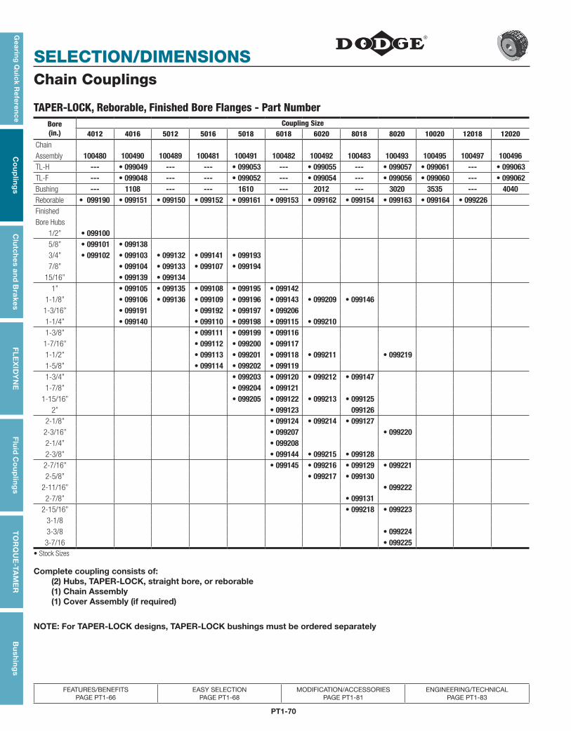
PT1-70
SELECTION/DIMENSIONS
Gea
ring
Qu
ick Re
fere
nc
eC
ou
plin
gs
Clu
tch
es an
d B
rakesF
LE
XID
YN
EF
luid
Co
up
ling
sT
OR
QU
E-TA
ME
RB
ush
ing
s
FEATURES/BENEFITS PAGE PT1-66
EASY SELECTION PAGE PT1-68
MODIFICATION/ACCESSORIES PAGE PT1-81
ENGINEERING/TECHNICAL PAGE PT1-83
Chain Couplings
TAPER-LOCK, Reborable, Finished Bore Flanges - Part NumberBore(in.)
Coupling Size4012 4016 5012 5016 5018 6018 6020 8018 8020 10020 12018 12020
ChainAssembly 100480 100490 100489 100481 100491 100482 100492 100483 100493 100495 100497 100496TL-H --- • 099049 --- --- • 099053 --- • 099055 --- • 099057 • 099061 --- • 099063TL-F --- • 099048 --- --- • 099052 --- • 099054 --- • 099056 • 099060 --- • 099062Bushing --- 1108 --- --- 1610 --- 2012 --- 3020 3535 --- 4040Reborable • 099190 • 099151 • 099150 • 099152 • 099161 • 099153 • 099162 • 099154 • 099163 • 099164 • 099226FinishedBore Hubs
1/2” • 0991005/8” • 099101 • 0991383/4” • 099102 • 099103 • 099132 • 099141 • 0991937/8” • 099104 • 099133 • 099107 • 099194
15/16” • 099139 • 0991341” • 099105 • 099135 • 099108 • 099195 • 099142
1-1/8” • 099106 • 099136 • 099109 • 099196 • 099143 • 099209 • 0991461-3/16” • 099191 • 099192 • 099197 • 0992061-1/4” • 099140 • 099110 • 099198 • 099115 • 0992101-3/8” • 099111 • 099199 • 0991161-7/16” • 099112 • 099200 • 0991171-1/2” • 099113 • 099201 • 099118 • 099211 • 0992191-5/8” • 099114 • 099202 • 0991191-3/4” • 099203 • 099120 • 099212 • 099147 1-7/8” • 099204 • 099121
1-15/16” • 099205 • 099122 • 099213 • 0991252” • 099123 099126
2-1/8” • 099124 • 099214 • 099127 2-3/16” • 099207 • 0992202-1/4” • 0992082-3/8” • 099144 • 099215 • 099128
2-7/16” • 099145 • 099216 • 099129 • 099221 2-5/8” • 099217 • 099130
2-11/16” • 0992222-7/8” • 099131
2-15/16” • 099218 • 099223 3-1/83-3/8 • 099224
3-7/16 • 099225• Stock Sizes
Complete coupling consists of: (2) Hubs, TAPER-LOCK, straight bore, or reborable (1) Chain Assembly (1) Cover Assembly (if required)
NOTE: For TAPER-LOCK designs, TAPER-LOCK bushings must be ordered separately
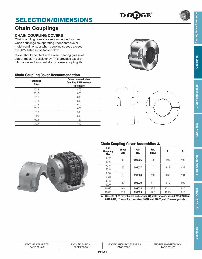
PT1-71
Gea
rin
g Q
uic
k R
efe
ren
ce
Co
up
ling
sC
lutc
h a
nd
Bra
kes
FL
EX
IDY
NE
Flu
id C
ou
plin
gs
TO
RQ
UE
-TA
ME
RB
ush
ing
s
FEATURES/BENEFITS PAGE PT1-66
EASY SELECTION PAGE PT1-68
MODIFICATION/ACCESSORIES PAGE PT1-81
ENGINEERING/TECHNICAL PAGE PT1-83
SELECTION/DIMENSIONSChain CouplingsCHAIN COUPLING COVERSChain coupling covers are recommended for use when couplings are operating under abrasive or moist conditions, or when coupling speeds exceed the RPM listed in the table below.
Cover should be filled with a roller bearing grease of soft or medium consistency. This provides excellent lubrication and substantially increases coupling life.
Chain Coupling Cover RecommendationCoupling
Size
Cover required whenCoupling RPM exceeds
this figure4012 875
4016 875
5016 800
5018 800
6018 675
6020 675
8018 500
8020 500
10020 450
12020 400
Chain Coupling Cover Assemblies ▲For
CouplingSize
CoverSize
PartNo.
Wt.(lbs.) A B
401240 099026 1.0 4.00 2.00
4016
501650 099027 1.3 5.13 2.38
5018
601860 099028 2.6 6.38 2.94
6020
801880 099029 5.1 8.19 4.00
8020
10020 100 099024 12.2 10.13 5.25
12020 120 099025 19.5 12.25 6.13
▲ Consists of (2) cover halves and screws; (4) seals for cover sizes 4012/4016 thru 8012/8020; (2) seals for cover sizes 10020 and 12020; and (2) cover gaskets.
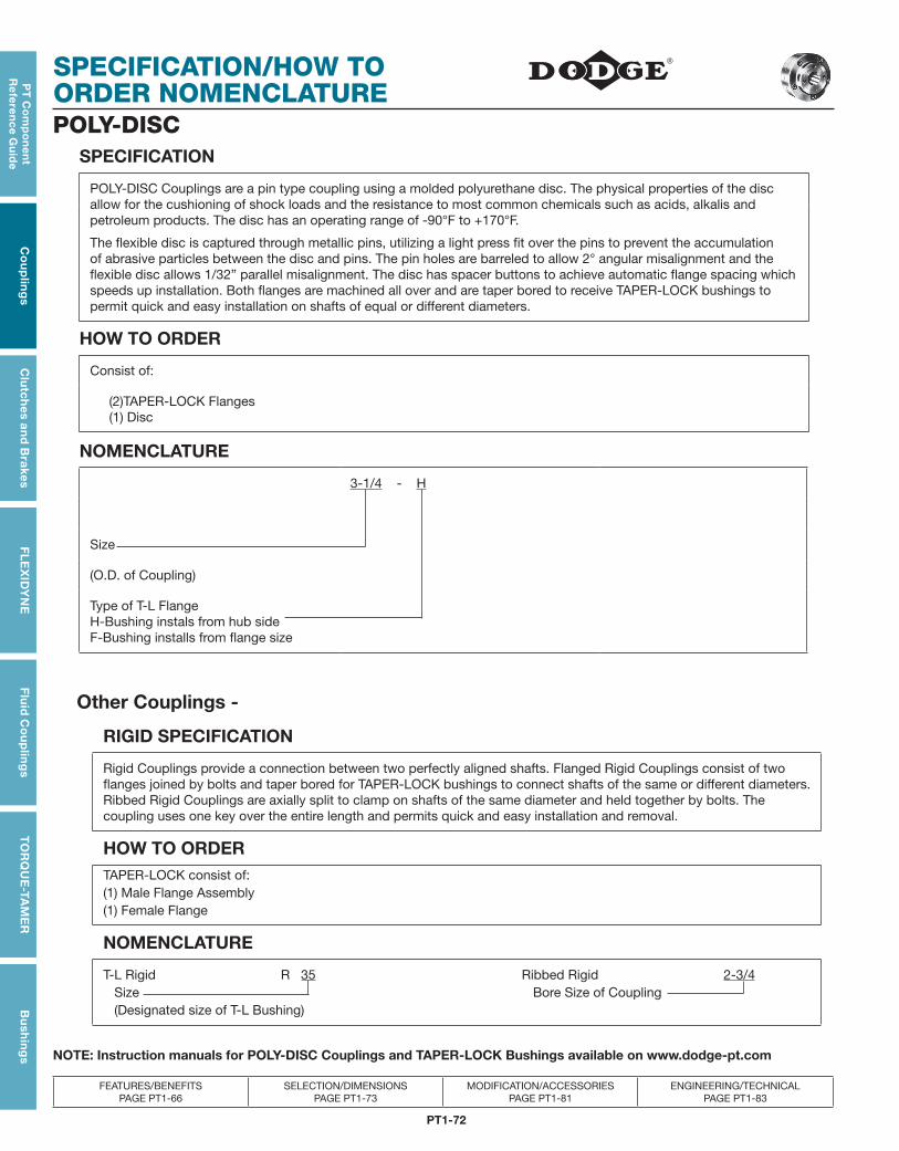
PT1-72
SPECIFICATION/HOW TO ORDER NOMENCLATURE
PT
Co
mp
on
en
t R
efe
ren
ce G
uid
eC
ou
plin
gs
Clu
tch
es an
d B
rakesF
LE
XID
YN
EF
luid
Co
up
ling
sT
OR
QU
E-TA
ME
RB
ush
ing
s
FEATURES/BENEFITS PAGE PT1-66
SELECTION/DIMENSIONS PAGE PT1-73
MODIFICATION/ACCESSORIES PAGE PT1-81
ENGINEERING/TECHNICAL PAGE PT1-83
POLY-DISCSPECIFICATION
POLY-DISC Couplings are a pin type coupling using a molded polyurethane disc. The physical properties of the disc allow for the cushioning of shock loads and the resistance to most common chemicals such as acids, alkalis and petroleum products. The disc has an operating range of -90°F to +170°F.
The flexible disc is captured through metallic pins, utilizing a light press fit over the pins to prevent the accumulation of abrasive particles between the disc and pins. The pin holes are barreled to allow 2° angular misalignment and the flexible disc allows 1/32” parallel misalignment. The disc has spacer buttons to achieve automatic flange spacing which speeds up installation. Both flanges are machined all over and are taper bored to receive TAPER-LOCK bushings to permit quick and easy installation on shafts of equal or different diameters.
HOW TO ORDER
Consist of:
(2)TAPER-LOCK Flanges (1) Disc
NOMENCLATURE
3-1/4 - H
Size
(O.D. of Coupling)
Type of T-L FlangeH-Bushing instals from hub sideF-Bushing installs from flange size
Other Couplings -
RIGID SPECIFICATION
Rigid Couplings provide a connection between two perfectly aligned shafts. Flanged Rigid Couplings consist of two flanges joined by bolts and taper bored for TAPER-LOCK bushings to connect shafts of the same or different diameters. Ribbed Rigid Couplings are axially split to clamp on shafts of the same diameter and held together by bolts. The coupling uses one key over the entire length and permits quick and easy installation and removal.
HOW TO ORDERTAPER-LOCK consist of:(1) Male Flange Assembly(1) Female Flange
NOMENCLATURE
T-L Rigid R 35 Ribbed Rigid 2-3/4 Size Bore Size of Coupling (Designated size of T-L Bushing)
NOTE: Instruction manuals for POLY-DISC Couplings and TAPER-LOCK Bushings available on www.dodge-pt.com
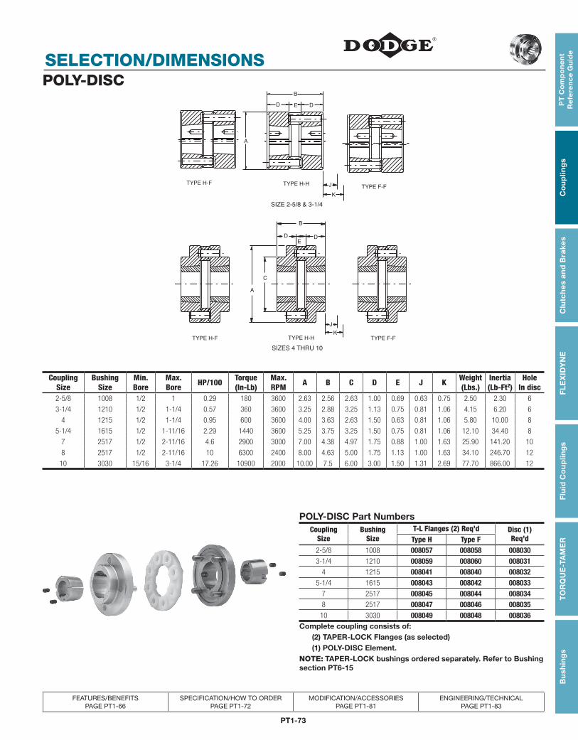
PT1-73
PT
Co
mp
on
en
t R
efe
ren
ce
Gu
ide
Co
up
ling
sC
lutc
hes
an
d B
rake
sF
LE
XID
YN
EF
luid
Co
up
ling
sT
OR
QU
E-T
AM
ER
Bu
shin
gs
FEATURES/BENEFITS PAGE PT1-66
SPECIFICATION/HOW TO ORDER PAGE PT1-72
MODIFICATION/ACCESSORIES PAGE PT1-81
ENGINEERING/TECHNICAL PAGE PT1-83
SELECTION/DIMENSIONSPOLY-DISC
SIZE 2-5/8 & 3-1/4
J
K
TYPE F-FTYPE H-HTYPE H-F
SIZES 4 THRU 10
E DD
A
B
DE
B
D
C
A
J
KTYPE H-H TYPE F-FTYPE H-F
CouplingSize
BushingSize
Min.Bore
Max.Bore HP/100 Torque
(In-Lb)Max.RPM A B C D E J K Weight
(Lbs.)Inertia(Lb-Ft2)
Hole In disc
2-5/8 1008 1/2 1 0.29 180 3600 2.63 2.56 2.63 1.00 0.69 0.63 0.75 2.50 2.30 6
3-1/4 1210 1/2 1-1/4 0.57 360 3600 3.25 2.88 3.25 1.13 0.75 0.81 1.06 4.15 6.20 6
4 1215 1/2 1-1/4 0.95 600 3600 4.00 3.63 2.63 1.50 0.63 0.81 1.06 5.80 10.00 8
5-1/4 1615 1/2 1-11/16 2.29 1440 3600 5.25 3.75 3.25 1.50 0.75 0.81 1.06 12.10 34.40 8
7 2517 1/2 2-11/16 4.6 2900 3000 7.00 4.38 4.97 1.75 0.88 1.00 1.63 25.90 141.20 10
8 2517 1/2 2-11/16 10 6300 2400 8.00 4.63 5.00 1.75 1.13 1.00 1.63 34.10 246.70 12
10 3030 15/16 3-1/4 17.26 10900 2000 10.00 7.5 6.00 3.00 1.50 1.31 2.69 77.70 866.00 12
POLY-DISC Part NumbersCoupling
SizeBushing
SizeT-L Flanges (2) Req’d Disc (1)
Req’dType H Type F2-5/8 1008 008057 008058 0080303-1/4 1210 008059 008060 008031
4 1215 008041 008040 0080325-1/4 1615 008043 008042 008033
7 2517 008045 008044 0080348 2517 008047 008046 00803510 3030 008049 008048 008036
Complete coupling consists of: (2) TAPER-LOCK Flanges (as selected) (1) POLY-DISC Element.NOTE: TAPER-LOCK bushings ordered separately. Refer to Bushing section PT6-15
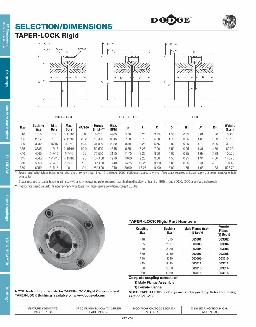
PT1-74
SELECTION/DIMENSIONS
PT
Co
mp
on
en
t R
efe
ren
ce G
uid
eC
ou
plin
gs
Clu
tch
es an
d B
rakesF
LE
XID
YN
EF
luid
Co
up
ling
sT
OR
QU
E-TA
ME
RB
ush
ing
s
FEATURES/BENEFITS PAGE PT1-66
SPECIFICATION/HOW TO ORDER PAGE PT1-72
MODIFICATION/ACCESSORIES PAGE PT1-81
ENGINEERING/TECHNICAL PAGE PT1-83
TAPER-LOCK Rigid
J
KK
J
K
C
AC
R35 TO R50
DD
R60
A
E
A C
R16 TO R30
DD
J
B B
E
B
D
E
D
Male Female
Size BushingSize
Min.Bore
Max.Bore HP/100 Torque
(In Lb)**Max.RPM A B C D E J* K† Weight
(Lbs.)R16 1615 1/2 1-11/16 8.0 5,050 4965 5.00 3.25 3.25 1.50 0.25 0.81 1.06 8.00
R25 2517 1/2 2-11/16 29.2 18,400 3545 7.00 3.75 5.00 1.75 0.25 1.00 1.63 19.10
R30 3030 15/16 3-1/4 50.5 31,800 2920 8.50 6.25 5.75 3.00 0.25 1.19 2.06 38.10
R35 3535 1-3/16 3-15/16 80.0 50,500 2545 9.75 7.25 7.00 3.50 0.25 1.31 2.69 62.20
R40 4040 1-7/16 4-7/16 120 75,500 2115 11.75 8.25 8.50 4.00 0.25 1.63 3.38 105.60
R45 4545 1-15/16 4-15/16 170 107,000 1910 13.00 9.25 9.50 4.50 0.25 1.94 4.06 146.70
R50 5050 2-7/16 5-5/16 233 147,000 1740 14.25 10.25 10.50 5.00 0.25 2.31 4.81 194.40
R60 6050 3-7/16 6 404 254,500 1240 20.00 13.25 16.00 5.00 1.75 1.63 4.38 526.70
* Space required to tighten bushing with shortened hex key in bushings 1615 through 5050. 6050 uses standard wrench. Also space required to loosen screws to permit removal of hub by a puller
† Space required to loosen bushing using screws as jack screws-no puller required. Use shortened hex key for bushing 1615 through 5050. 6050 uses standard wrench
** Ratings are based on uniform, non-reversing type loads. For more severe conditions, consult DODGE
TAPER-LOCK Rigid Part Numbers
CouplingSize
BushingSize
Male Flange Assy(1) Req’d
Female Flange
(1) Req’dR16 1615 003001 003002R25 2517 003003 003004R30 3030 003005 003006R35 3535 003007 003008R40 4040 003009 003010R45 4545 003011 003012R50 5050 003013 003014R60 6050 003015 003016
Complete coupling consists of: (1) Male Flange Assembly (1) Female FlangeNOTE: TAPER-LOCK bushings ordered separately. Refer to bushing section PT6-16
NOTE: Instruction manuals for TAPER-LOCK Rigid Couplings and TAPER-LOCK Bushings available on www.dodge-pt.com
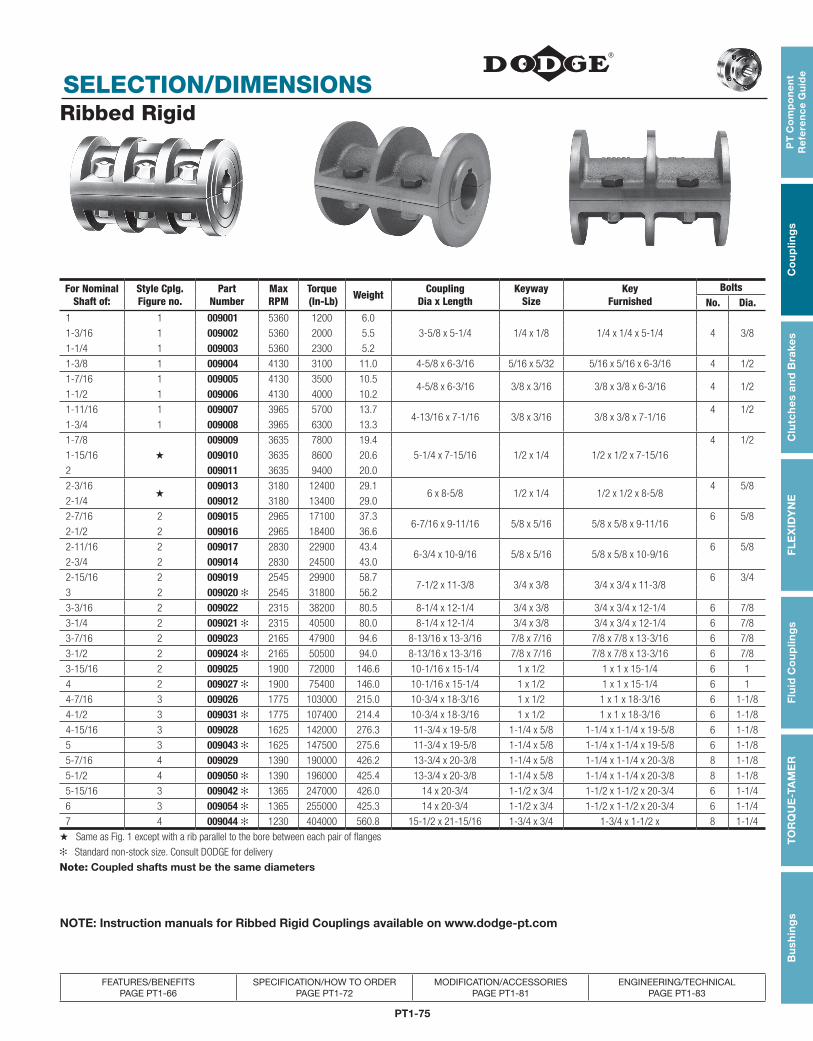
PT1-75
PT
Co
mp
on
en
t R
efe
ren
ce
Gu
ide
Co
up
ling
sC
lutc
hes
an
d B
rake
sF
LE
XID
YN
EF
luid
Co
up
ling
sT
OR
QU
E-T
AM
ER
Bu
shin
gs
FEATURES/BENEFITS PAGE PT1-66
SPECIFICATION/HOW TO ORDER PAGE PT1-72
MODIFICATION/ACCESSORIES PAGE PT1-81
ENGINEERING/TECHNICAL PAGE PT1-83
SELECTION/DIMENSIONSRibbed Rigid
For Nominal Shaft of:
Style Cplg. Figure no.
Part Number
Max RPM
Torque (In-Lb) Weight Coupling
Dia x LengthKeyway
SizeKey
FurnishedBolts
No. Dia.1 1 009001 5360 1200 6.0
3-5/8 x 5-1/4 1/4 x 1/8 1/4 x 1/4 x 5-1/4 4 3/81-3/16 1 009002 5360 2000 5.5
1-1/4 1 009003 5360 2300 5.2
1-3/8 1 009004 4130 3100 11.0 4-5/8 x 6-3/16 5/16 x 5/32 5/16 x 5/16 x 6-3/16 4 1/2
1-7/16 1 009005 4130 3500 10.54-5/8 x 6-3/16 3/8 x 3/16 3/8 x 3/8 x 6-3/16 4 1/2
1-1/2 1 009006 4130 4000 10.2
1-11/16 1 009007 3965 5700 13.74-13/16 x 7-1/16 3/8 x 3/16 3/8 x 3/8 x 7-1/16
4 1/2
1-3/4 1 009008 3965 6300 13.3
1-7/8
★
009009 3635 7800 19.4
5-1/4 x 7-15/16 1/2 x 1/4 1/2 x 1/2 x 7-15/16
4 1/2
1-15/16 009010 3635 8600 20.6
2 009011 3635 9400 20.0
2-3/16★
009013 3180 12400 29.16 x 8-5/8 1/2 x 1/4 1/2 x 1/2 x 8-5/8
4 5/8
2-1/4 009012 3180 13400 29.0
2-7/16 2 009015 2965 17100 37.36-7/16 x 9-11/16 5/8 x 5/16 5/8 x 5/8 x 9-11/16
6 5/8
2-1/2 2 009016 2965 18400 36.6
2-11/16 2 009017 2830 22900 43.46-3/4 x 10-9/16 5/8 x 5/16 5/8 x 5/8 x 10-9/16
6 5/8
2-3/4 2 009014 2830 24500 43.0
2-15/16 2 009019 2545 29900 58.77-1/2 x 11-3/8 3/4 x 3/8 3/4 x 3/4 x 11-3/8
6 3/4
3 2 009020 ✻ 2545 31800 56.2
3-3/16 2 009022 2315 38200 80.5 8-1/4 x 12-1/4 3/4 x 3/8 3/4 x 3/4 x 12-1/4 6 7/8
3-1/4 2 009021 ✻ 2315 40500 80.0 8-1/4 x 12-1/4 3/4 x 3/8 3/4 x 3/4 x 12-1/4 6 7/8
3-7/16 2 009023 2165 47900 94.6 8-13/16 x 13-3/16 7/8 x 7/16 7/8 x 7/8 x 13-3/16 6 7/8
3-1/2 2 009024 ✻ 2165 50500 94.0 8-13/16 x 13-3/16 7/8 x 7/16 7/8 x 7/8 x 13-3/16 6 7/8
3-15/16 2 009025 1900 72000 146.6 10-1/16 x 15-1/4 1 x 1/2 1 x 1 x 15-1/4 6 1
4 2 009027 ✻ 1900 75400 146.0 10-1/16 x 15-1/4 1 x 1/2 1 x 1 x 15-1/4 6 1
4-7/16 3 009026 1775 103000 215.0 10-3/4 x 18-3/16 1 x 1/2 1 x 1 x 18-3/16 6 1-1/8
4-1/2 3 009031 ✻ 1775 107400 214.4 10-3/4 x 18-3/16 1 x 1/2 1 x 1 x 18-3/16 6 1-1/8
4-15/16 3 009028 1625 142000 276.3 11-3/4 x 19-5/8 1-1/4 x 5/8 1-1/4 x 1-1/4 x 19-5/8 6 1-1/8
5 3 009043 ✻ 1625 147500 275.6 11-3/4 x 19-5/8 1-1/4 x 5/8 1-1/4 x 1-1/4 x 19-5/8 6 1-1/8
5-7/16 4 009029 1390 190000 426.2 13-3/4 x 20-3/8 1-1/4 x 5/8 1-1/4 x 1-1/4 x 20-3/8 8 1-1/8
5-1/2 4 009050 ✻ 1390 196000 425.4 13-3/4 x 20-3/8 1-1/4 x 5/8 1-1/4 x 1-1/4 x 20-3/8 8 1-1/8
5-15/16 3 009042 ✻ 1365 247000 426.0 14 x 20-3/4 1-1/2 x 3/4 1-1/2 x 1-1/2 x 20-3/4 6 1-1/4
6 3 009054 ✻ 1365 255000 425.3 14 x 20-3/4 1-1/2 x 3/4 1-1/2 x 1-1/2 x 20-3/4 6 1-1/4
7 4 009044 ✻ 1230 404000 560.8 15-1/2 x 21-15/16 1-3/4 x 3/4 1-3/4 x 1-1/2 x 8 1-1/4
★ Same as Fig. 1 except with a rib parallel to the bore between each pair of flanges
✻ Standard non-stock size. Consult DODGE for delivery
Note: Coupled shafts must be the same diameters
NOTE: Instruction manuals for Ribbed Rigid Couplings available on www.dodge-pt.com
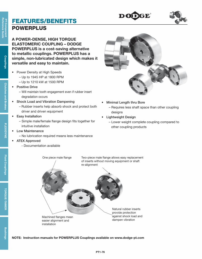
PT1-76
FEATURES/BENEFITS
PT
Co
mp
on
en
t R
efe
ren
ce G
uid
eC
ou
plin
gs
Clu
tch
es an
d B
rakesF
LE
XID
YN
EF
luid
Co
up
ling
sT
OR
QU
E-TA
ME
RB
ush
ing
s
A POWER-DENSE, HIGH TORQUE ELASTOMERIC COUPLING – DODGE POWERPLUS is a cost-saving alternative to metallic couplings. POWERPLUS has a simple, non-lubricated design which makes it versatile and easy to maintain.
• Power Density at High Speeds
– Up to 1945 HP at 1800 RPM
– Up to 1210 kW at 1500 RPM
• PositiveDrive
– Will maintain tooth engagement even if rubber insert
degradation occurs
• ShockLoadandVibrationDampening
– Rubber inserts help absorb shock and protect both
driver and driven equipment
• EasyInstallation
– Simple male/female flange design fits together for
intuitive installation
• LowMaintenance
– No lubrication required means less maintenance
• ATEXApproved
- Documentation available
POWERPLUS
• MinimalLengththruBore
– Requires less shaft space than other coupling
designs
• LightweightDesign
– Lower weight complete coupling compared to
other coupling products
One piece male flange
Machined flanges mean easier alignment and installation
Two-piece male flange allows easy replacement of inserts without moving equipment or shaft re-alignment
Natural rubber inserts provide protection against shock load and dampen vibration
NOTE: Instruction manuals for POWERPLUS Couplings available on www.dodge-pt.com
PT1-77
PT
Co
mp
on
en
t R
efe
ren
ce
Gu
ide
Co
up
ling
sC
lutc
hes
an
d B
rake
sF
LE
XID
YN
EF
luid
Co
up
ling
sT
OR
QU
E-T
AM
ER
Bu
shin
gs
FEATURES/BENEFITS PAGE PT1-76
SELECTION PAGE PT1-78
MODIFICATION/ACCESSORIES PAGE PT1-81
ENGINEERING/TECHNICAL PAGE PT1-83
SPECIFICATION/HOW TO ORDER/NOMENCLATUREPOWERPLUS
SPECIFICATIONDODGE POWERPLUS couplings are hybrid jaw style coupling which utilize elastomeric inserts held in compression between interlocking teeth of male and female flanges. The flanges are offered as a finished bore design and are machined all over, in order to offer a coupling which is inherently well balanced design and suitable for operation at high speeds.
With interlocking metallic teeth, the flanges provide positive drive and negate the potential for catastrophic failure. Additionally, the rubber inserts are protected from exposure to contaminants as a result of the flange engagement design. The inserts are suitable for operation from -30˚ C to +80˚ C (-22˚ F to +176˚ F) and are readily replaced by disengaging the male flange from the female flange.
HOW TO ORDERComplete coupling consist of:
(1) Male flange (1 piece or 2 piece design)
(1) Female flange (Includes 1 set of inserts)
NOMENCLATURE DPP 58
DODGE POWERPLUS
Size
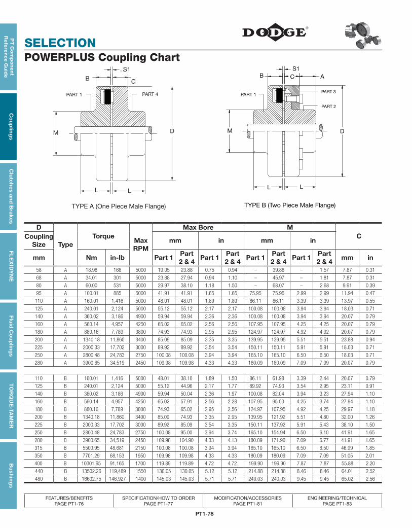
PT1-78
SELECTION
PT
Co
mp
on
en
t R
efe
ren
ce G
uid
eC
ou
plin
gs
Clu
tch
es an
d B
rakesF
LE
XID
YN
EF
luid
Co
up
ling
sT
OR
QU
E-TA
ME
RB
ush
ing
s
FEATURES/BENEFITS PAGE PT1-76
SPECIFICATION/HOW TO ORDER PAGE PT1-77
MODIFICATION/ACCESSORIES PAGE PT1-81
ENGINEERING/TECHNICAL PAGE PT1-83
D
TypeTorque
Max RPM
Max Bore M CCoupling
Sizemm in mm in
mm Nm in-lb Part 1Part 2 & 4
Part 1Part 2 & 4
Part 1Part 2 & 4
Part 1Part 2 & 4
mm in
58 A 18.98 168 5000 19.05 23.88 0.75 0.94 – 39.88 – 1.57 7.87 0.31
68 A 34.01 301 5000 23.88 27.94 0.94 1.10 – 45.97 – 1.81 7.87 0.31
80 A 60.00 531 5000 29.97 38.10 1.18 1.50 – 68.07 – 2.68 9.91 0.39
95 A 100.01 885 5000 41.91 41.91 1.65 1.65 75.95 75.95 2.99 2.99 11.94 0.47
110 A 160.01 1,416 5000 48.01 48.01 1.89 1.89 86.11 86.11 3.39 3.39 13.97 0.55
125 A 240.01 2,124 5000 55.12 55.12 2.17 2.17 100.08 100.08 3.94 3.94 18.03 0.71
140 A 360.02 3,186 4900 59.94 59.94 2.36 2.36 100.08 100.08 3.94 3.94 20.07 0.79
160 A 560.14 4,957 4250 65.02 65.02 2.56 2.56 107.95 107.95 4.25 4.25 20.07 0.79
180 A 880.16 7,789 3800 74.93 74.93 2.95 2.95 124.97 124.97 4.92 4.92 20.07 0.79
200 A 1340.18 11,860 3400 85.09 85.09 3.35 3.35 139.95 139.95 5.51 5.51 23.88 0.94
225 A 2000.33 17,702 3000 89.92 89.92 3.54 3.54 150.11 150.11 5.91 5.91 18.03 0.71
250 A 2800.48 24,783 2750 100.08 100.08 3.94 3.94 165.10 165.10 6.50 6.50 18.03 0.71
280 A 3900.65 34,519 2450 109.98 109.98 4.33 4.33 180.09 180.09 7.09 7.09 20.07 0.79
110 B 160.01 1,416 5000 48.01 38.10 1.89 1.50 86.11 61.98 3.39 2.44 20.07 0.79
125 B 240.01 2,124 5000 55.12 44.96 2.17 1.77 89.92 74.93 3.54 2.95 23.11 0.91
140 B 360.02 3,186 4900 59.94 50.04 2.36 1.97 100.08 82.04 3.94 3.23 27.94 1.10
160 B 560.14 4,957 4250 65.02 57.91 2.56 2.28 107.95 95.00 4.25 3.74 27.94 1.10
180 B 880.16 7,789 3800 74.93 65.02 2.95 2.56 124.97 107.95 4.92 4.25 29.97 1.18
200 B 1340.18 11,860 3400 85.09 74.93 3.35 2.95 139.95 121.92 5.51 4.80 32.00 1.26
225 B 2000.33 17,702 3000 89.92 85.09 3.54 3.35 150.11 137.92 5.91 5.43 38.10 1.50
250 B 2800.48 24,783 2750 100.08 95.00 3.94 3.74 165.10 154.94 6.50 6.10 41.91 1.65
280 B 3900.65 34,519 2450 109.98 104.90 4.33 4.13 180.09 171.96 7.09 6.77 41.91 1.65
315 B 5500.95 48,681 2150 100.08 100.08 3.94 3.94 165.10 165.10 6.50 6.50 46.99 1.85
350 B 7701.29 68,153 1950 109.98 109.98 4.33 4.33 180.09 180.09 7.09 7.09 51.05 2.01
400 B 10301.65 91,165 1700 119.89 119.89 4.72 4.72 199.90 199.90 7.87 7.87 55.88 2.20
440 B 13502.26 119,489 1550 130.05 130.05 5.12 5.12 214.88 214.88 8.46 8.46 64.01 2.52
480 B 16602.75 146,927 1400 145.03 145.03 5.71 5.71 240.03 240.03 9.45 9.45 65.02 2.56
POWERPLUS Coupling Chart
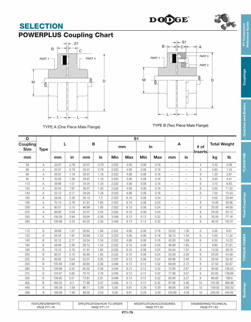
PT1-79
PT
Co
mp
on
en
t R
efe
ren
ce
Gu
ide
Co
up
ling
sC
lutc
hes
an
d B
rake
sF
LE
XID
YN
EF
luid
Co
up
ling
sT
OR
QU
E-T
AM
ER
Bu
shin
gs
SELECTION
FEATURES/BENEFITS PAGE PT1-76
SPECIFICATION/HOW TO ORDER PAGE PT1-77
MODIFICATION/ACCESSORIES PAGE PT1-81
ENGINEERING/TECHNICAL PAGE PT1-83
POWERPLUS Coupling Chart
D
TypeL B
S1 A
# of Inserts
Total WeightCoupling Size
mm in
mm mm in mm in Min Max Min Max mm in kg lb
58 A 20.07 0.79 20.07 0.79 2.032 4.06 0.08 0.16 – – 4 0.45 0.99
68 A 20.07 0.79 20.07 0.79 2.032 4.06 0.08 0.16 – – 5 0.65 1.43
80 A 29.97 1.18 29.97 1.18 2.032 4.06 0.08 0.16 – – 6 1.30 2.87
95 A 35.05 1.38 29.97 1.18 2.032 4.06 0.08 0.16 – – 6 2.00 4.41
110 A 39.88 1.57 34.04 1.34 2.032 4.06 0.08 0.16 – – 6 3.10 6.83
125 A 50.04 1.97 36.07 1.42 2.032 4.06 0.08 0.16 – – 6 5.00 11.02
140 A 55.12 2.17 34.04 1.34 2.032 4.06 0.08 0.16 – – 6 7.00 15.43
160 A 59.94 2.36 38.10 1.5 2.032 6.10 0.08 0.24 – – 7 9.50 20.94
180 A 70.10 2.76 41.91 1.65 2.032 6.10 0.08 0.24 – – 8 14.00 30.86
200 A 80.01 3.15 46.99 1.85 2.032 6.10 0.08 0.24 – – 8 20.00 44.09
225 A 89.92 3.54 52.07 2.05 2.032 6.10 0.08 0.24 – – 8 25.00 55.12
250 A 100.08 3.94 59.94 2.36 3.048 8.13 0.12 0.32 – – 8 35.00 77.16
280 A 109.98 4.33 65.02 2.56 3.048 8.13 0.12 0.32 – – 8 46.50 102.51
110 B 39.88 1.57 26.92 1.06 2.032 4.06 0.08 0.16 33.02 1.30 6 3.00 6.61
125 B 50.04 1.97 30.99 1.22 2.032 4.06 0.08 0.16 38.10 1.50 6 5.00 11.02
140 B 55.12 2.17 34.04 1.34 2.032 4.06 0.08 0.16 42.93 1.69 6 6.50 14.33
160 B 59.94 2.36 39.12 1.54 2.032 6.10 0.08 0.24 46.99 1.85 7 9.80 21.61
180 B 70.10 2.76 41.91 1.65 2.032 6.10 0.08 0.24 50.04 1.97 8 13.50 29.76
200 B 80.01 3.15 46.99 1.85 2.032 6.10 0.08 0.24 53.09 2.09 8 20.00 44.09
225 B 89.92 3.54 52.07 2.05 2.032 6.10 0.08 0.24 60.96 2.40 8 26.50 58.42
250 B 100.08 3.94 59.94 2.36 3.048 8.13 0.12 0.32 69.09 2.72 8 37.50 82.67
280 B 109.98 4.33 65.02 2.56 3.048 8.13 0.12 0.32 72.90 2.87 8 49.00 108.03
315 B 124.97 4.92 70.10 2.76 3.048 8.13 0.12 0.32 77.98 3.07 9 63.00 138.89
350 B 139.95 5.51 73.91 2.91 3.048 8.13 0.12 0.32 83.06 3.27 9 86.00 189.6
400 B 160.02 6.3 77.98 3.07 3.048 8.13 0.12 0.32 87.88 3.46 10 122.00 268.96
440 B 180.09 7.09 86.11 3.39 5.08 9.91 0.20 0.39 99.06 3.90 10 159.00 350.53
480 B 189.99 7.48 89.92 3.54 5.08 9.91 0.20 0.39 103.89 4.09 10 200.00 440.92
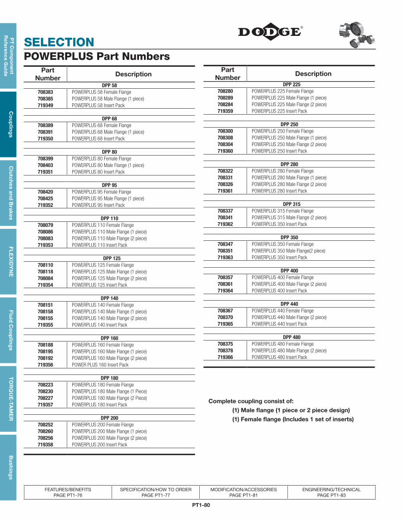
PT1-80
SELECTION
PT
Co
mp
on
en
t R
efe
ren
ce G
uid
eC
ou
plin
gs
Clu
tch
es an
d B
rakesF
LE
XID
YN
EF
luid
Co
up
ling
sT
OR
QU
E-TA
ME
RB
ush
ing
s
FEATURES/BENEFITS PAGE PT1-76
SPECIFICATION/HOW TO ORDER PAGE PT1-77
MODIFICATION/ACCESSORIES PAGE PT1-81
ENGINEERING/TECHNICAL PAGE PT1-83
POWERPLUS Part NumbersPart
Number Description
DPP 58708383 POWERPLUS 58 Female Flange708385 POWERPLUS 58 Male Flange (1 piece)719349 POWERPLUS 58 Insert Pack
DPP 68708389 POWERPLUS 68 Female Flange708391 POWERPLUS 68 Male Flange (1 piece)719350 POWERPLUS 68 Insert Pack
DPP 80708399 POWERPLUS 80 Female Flange708403 POWERPLUS 80 Male Flange (1 piece)719351 POWERPLUS 80 Insert Pack
DPP 95708420 POWERPLUS 95 Female Flange708425 POWERPLUS 95 Male Flange (1 piece)719352 POWERPLUS 95 Insert Pack
DPP 110 708079 POWERPLUS 110 Female Flange708086 POWERPLUS 110 Male Flange (1 piece)708083 POWERPLUS 110 Male Flange (2 piece)719353 POWERPLUS 110 Insert Pack
DPP 125708110 POWERPLUS 125 Female Flange708118 POWERPLUS 125 Male Flange (1 piece)708084 POWERPLUS 125 Male Flange (2 piece)719354 POWERPLUS 125 Insert Pack
DPP 140708151 POWERPLUS 140 Female Flange708158 POWERPLUS 140 Male Flange (1 piece)708155 POWERPLUS 140 Male Flange (2 piece)719355 POWERPLUS 140 Insert Pack
DPP 160708188 POWERPLUS 160 Female Flange708195 POWERPLUS 160 Male Flange (1 piece)708192 POWERPLUS 160 Male Flange (2 piece)719356 POWER PLUS 160 Insert Pack
DPP 180708223 POWERPLUS 180 Female Flange708230 POWERPLUS 180 Male Flange (1 Piece)708227 POWERPLUS 180 Male Flange (2 Piece)719357 POWERPLUS 180 Insert Pack
DPP 200708252 POWERPLUS 200 Female Flange708260 POWERPLUS 200 Male Flange (1 piece)708256 POWERPLUS 200 Male Flange (2 piece)719358 POWERPLUS 200 Insert Pack
Part Number
Description
DPP 225708280 POWERPLUS 225 Female Flange708289 POWERPLUS 225 Male Flange (1 piece)708284 POWERPLUS 225 Male Flange (2 piece)719359 POWERPLUS 225 Insert Pack
DPP 250708300 POWERPLUS 250 Female Flange708308 POWERPLUS 250 Male Flange (1 piece)708304 POWERPLUS 250 Male Flange (2 piece)719360 POWERPLUS 250 Insert Pack
DPP 280708322 POWERPLUS 280 Female Flange708331 POWERPLUS 280 Male Flange (1 piece)708326 POWERPLUS 280 Male Flange (2 piece)719361 POWERPLUS 280 Insert Pack
DPP 315708337 POWERPLUS 315 Female Flange708341 POWERPLUS 315 Male Flange (2 piece)719362 POWERPLUS 350 Insert Pack
DPP 350708347 POWERPLUS 350 Female Flange708351 POWERPLUS 350 Male Flange(2 piece)719363 POWERPLUS 350 Insert Pack
DPP 400708357 POWERPLUS 400 Female Flange708361 POWERPLUS 400 Male Flange (2 piece)719364 POWERPLUS 400 Insert Pack
DPP 440708367 POWERPLUS 440 Female Flange708370 POWERPLUS 440 Male Flange (2 piece)719365 POWERPLUS 440 Insert Pack
DPP 480708375 POWERPLUS 480 Female Flange708378 POWERPLUS 480 Male Flange (2 piece)719366 POWERPLUS 480 Insert Pack
Complete coupling consist of:
(1) Male flange (1 piece or 2 piece design)
(1) Female flange (Includes 1 set of inserts)
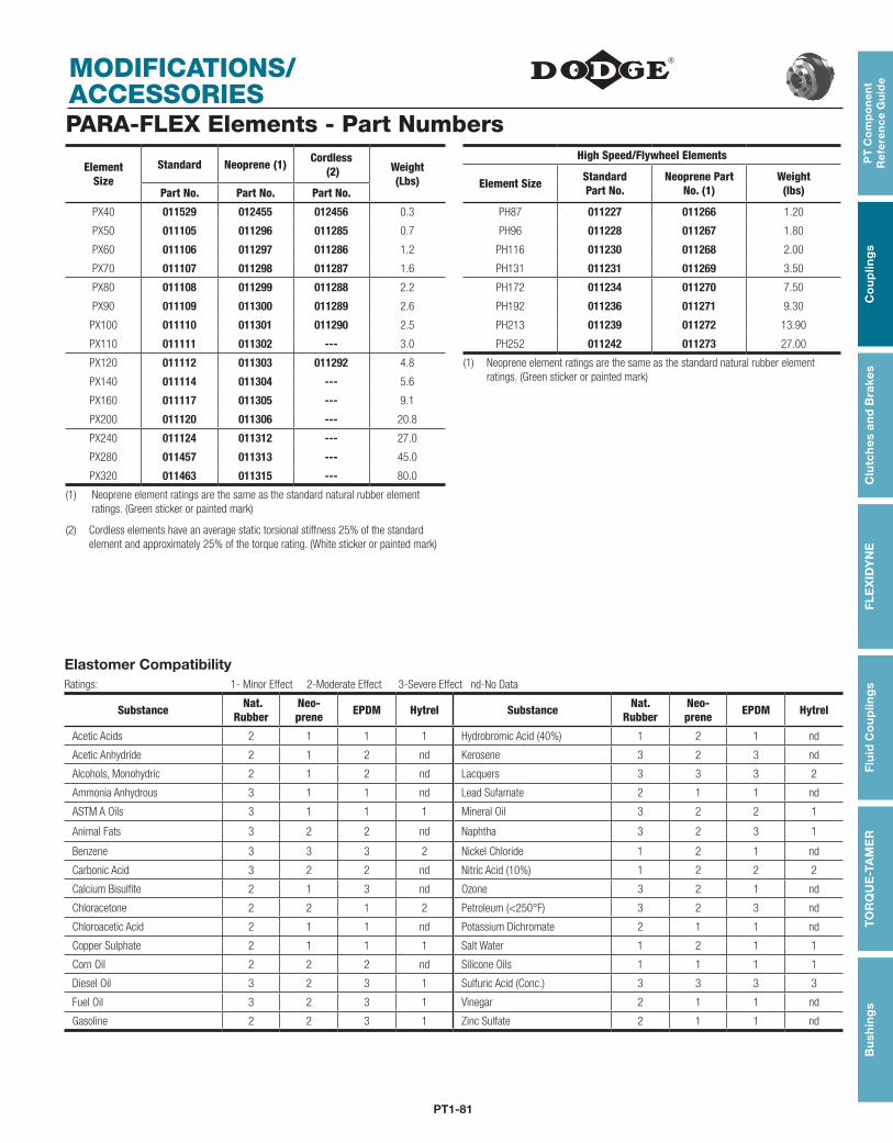
PT1-81
PT
Co
mp
on
en
t R
efe
ren
ce
Gu
ide
Co
up
ling
sC
lutc
hes
an
d B
rake
sF
LE
XID
YN
EF
luid
Co
up
ling
sT
OR
QU
E-T
AM
ER
Bu
shin
gs
MODIFICATIONS/ ACCESSORIESPARA-FLEX Elements - Part Numbers
ElementSize
Standard Neoprene (1) Cordless (2) Weight
(Lbs)
High Speed/Flywheel Elements
Element Size Standard Part No.
Neoprene Part No. (1)
Weight (lbs)Part No. Part No. Part No.
PX40 011529 012455 012456 0.3 PH87 011227 011266 1.20
PX50 011105 011296 011285 0.7 PH96 011228 011267 1.80
PX60 011106 011297 011286 1.2 PH116 011230 011268 2.00
PX70 011107 011298 011287 1.6 PH131 011231 011269 3.50
PX80 011108 011299 011288 2.2 PH172 011234 011270 7.50
PX90 011109 011300 011289 2.6 PH192 011236 011271 9.30
PX100 011110 011301 011290 2.5 PH213 011239 011272 13.90
PX110 011111 011302 --- 3.0 PH252 011242 011273 27.00
PX120 011112 011303 011292 4.8 (1) Neoprene element ratings are the same as the standard natural rubber element ratings. (Green sticker or painted mark)PX140 011114 011304 --- 5.6
PX160 011117 011305 --- 9.1
PX200 011120 011306 --- 20.8
PX240 011124 011312 --- 27.0
PX280 011457 011313 --- 45.0
PX320 011463 011315 --- 80.0
(1) Neoprene element ratings are the same as the standard natural rubber element ratings. (Green sticker or painted mark)
(2) Cordless elements have an average static torsional stiffness 25% of the standard element and approximately 25% of the torque rating. (White sticker or painted mark)
Elastomer CompatibilityRatings: 1- Minor Effect 2-Moderate Effect 3-Severe Effect nd-No Data
Substance Nat.Rubber
Neo- prene EPDM Hytrel Substance Nat.
RubberNeo- prene EPDM Hytrel
Acetic Acids 2 1 1 1 Hydrobromic Acid (40%) 1 2 1 nd
Acetic Anhydride 2 1 2 nd Kerosene 3 2 3 nd
Alcohols, Monohydric 2 1 2 nd Lacquers 3 3 3 2
Ammonia Anhydrous 3 1 1 nd Lead Sufamate 2 1 1 nd
ASTM A Oils 3 1 1 1 Mineral Oil 3 2 2 1
Animal Fats 3 2 2 nd Naphtha 3 2 3 1
Benzene 3 3 3 2 Nickel Chloride 1 2 1 nd
Carbonic Acid 3 2 2 nd Nitric Acid (10%) 1 2 2 2
Calcium Bisulfite 2 1 3 nd Ozone 3 2 1 nd
Chloracetone 2 2 1 2 Petroleum (<250°F) 3 2 3 nd
Chloroacetic Acid 2 1 1 nd Potassium Dichromate 2 1 1 nd
Copper Sulphate 2 1 1 1 Salt Water 1 2 1 1
Corn Oil 2 2 2 nd Silicone Oils 1 1 1 1
Diesel Oil 3 2 3 1 Sulfuric Acid (Conc.) 3 3 3 3
Fuel Oil 3 2 3 1 Vinegar 2 1 1 nd
Gasoline 2 2 3 1 Zinc Sulfate 2 1 1 nd
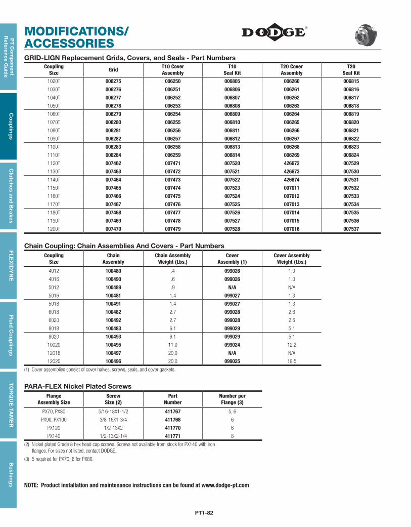
PT1-82
MODIFICATIONS/ ACCESSORIES
PT
Co
mp
on
en
t R
efe
ren
ce G
uid
eC
ou
plin
gs
Clu
tch
es an
d B
rakesF
LE
XID
YN
EF
luid
Co
up
ling
sT
OR
QU
E-TA
ME
RB
ush
ing
s
GRID-LIGN Replacement Grids, Covers, and Seals - Part NumbersCoupling
Size Grid T10 CoverAssembly
T10Seal Kit
T20 CoverAssembly
T20Seal Kit
1020T 006275 006250 006805 006260 006815
1030T 006276 006251 006806 006261 006816
1040T 006277 006252 006807 006262 006817
1050T 006278 006253 006808 006263 006818
1060T 006279 006254 006809 006264 006819
1070T 006280 006255 006810 006265 006820
1080T 006281 006256 006811 006266 006821
1090T 006282 006257 006812 006267 006822
1100T 006283 006258 006813 006268 006823
1110T 006284 006259 006814 006269 006824
1120T 007462 007471 007520 426672 007529
1130T 007463 007472 007521 426673 007530
1140T 007464 007473 007522 426674 007531
1150T 007465 007474 007523 007011 007532
1160T 007466 007475 007524 007012 007533
1170T 007467 007476 007525 007013 007534
1180T 007468 007477 007526 007014 007535
1190T 007469 007478 007527 007015 007536
1200T 007470 007479 007528 007016 007537
Chain Coupling: Chain Assemblies And Covers - Part NumbersCoupling
SizeChain
AssemblyChain Assembly
Weight (Lbs.)Cover
Assembly (1)Cover Assembly
Weight (Lbs.)
4012 100480 .4 099026 1.0
4016 100490 .6 099026 1.0
5012 100489 .9 N/A N/A
5016 100481 1.4 099027 1.3
5018 100491 1.4 099027 1.3
6018 100482 2.7 099028 2.6
6020 100492 2.7 099028 2.6
8018 100483 6.1 099029 5.1
8020 100493 6.1 099029 5.1
10020 100495 11.0 099024 12.2
12018 100497 20.0 N/A N/A
12020 100496 20.0 099025 19.5
(1) Cover assemblies consist of cover halves, screws, seals, and cover gaskets.
PARA-FLEX Nickel Plated ScrewsFlange
Assembly SizeScrew
Size (2)Part
NumberNumber perFlange (3)
PX70, PX80 5/16-18X1-1/2 411767 5, 6
PX90, PX100 3/8-16X1-3/4 411768 6
PX120 1/2-13X2 411770 6
PX140 1/2-13X2-1/4 411771 8
(2) Nickel plated Grade 8 hex head cap screws. Screws not available from stock for PX140 with iron flanges. For sizes not listed, contact DODGE.
(3) 5 required for PX70; 6 for PX80.
NOTE: Product installation and maintenance instructions can be found at www.dodge-pt.com
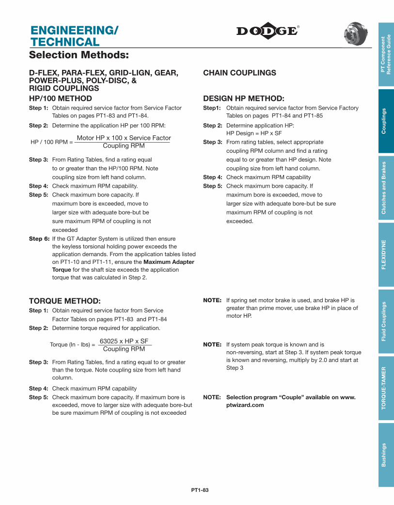
PT1-83
PT
Co
mp
on
en
t R
efe
ren
ce
Gu
ide
Co
up
ling
sC
lutc
hes
an
d B
rake
sF
LE
XID
YN
EF
luid
Co
up
ling
sT
OR
QU
E-T
AM
ER
Bu
shin
gs
ENGINEERING/ TECHNICALSelection Methods:
D-FLEX, PARA-FLEX, GRID-LIGN, GEAR, POWER-PLUS, POLY-DISC, & RIGID COUPLINGS
CHAIN COUPLINGS
HP/100 METHOD DESIGN HP METHOD:Step 1: Obtain required service factor from Service Factor
Tables on pages PT1-83 and PT1-84.Step1: Obtain required service factor from Service Factory
Tables on pages PT1-84 and PT1-85
Step 2: Determine the application HP per 100 RPM: Step 2: Determine application HP: HP Design = HP x SF
HP / 100 RPM = Step 3: From rating tables, select appropriate
coupling RPM column and find a rating
Step 3: From Rating Tables, find a rating equal equal to or greater than HP design. Note
to or greater than the HP/100 RPM. Note coupling size from left hand column.
coupling size from left hand column. Step 4: Check maximum RPM capability
Step 4: Check maximum RPM capability. Step 5: Check maximum bore capacity. If
Step 5: Check maximum bore capacity. If maximum bore is exceeded, move to
maximum bore is exceeded, move to larger size with adequate bore-but be sure
larger size with adequate bore-but be maximum RPM of coupling is not
sure maximum RPM of coupling is not exceeded.
exceeded
Step 6: If the GT Adapter System is utilized then ensure the keyless torsional holding power exceeds the application demands. From the application tables listed on PT1-10 and PT1-11, ensure the Maximum Adapter Torque for the shaft size exceeds the application torque that was calculated in Step 2.
TORQUE METHOD: NOTE: If spring set motor brake is used, and brake HP is greater than prime mover, use brake HP in place of motor HP.
Step 1: Obtain required service factor from Service
Factor Tables on pages PT1-83 and PT1-84
Step 2: Determine torque required for application.
Torque (In - lbs) = NOTE: If system peak torque is known and isnon-reversing, start at Step 3. If system peak torque is known and reversing, multiply by 2.0 and start at Step 3
Step 3: From Rating Tables, find a rating equal to or greater than the torque. Note coupling size from left hand column.
Step 4: Check maximum RPM capability
Step 5: Check maximum bore capacity. If maximum bore is exceeded, move to larger size with adequate bore-but be sure maximum RPM of coupling is not exceeded
NOTE: Selection program “Couple” available on www.ptwizard.com
Motor HP x 100 x Service FactorCoupling RPM
63025 x HP x SFCoupling RPM
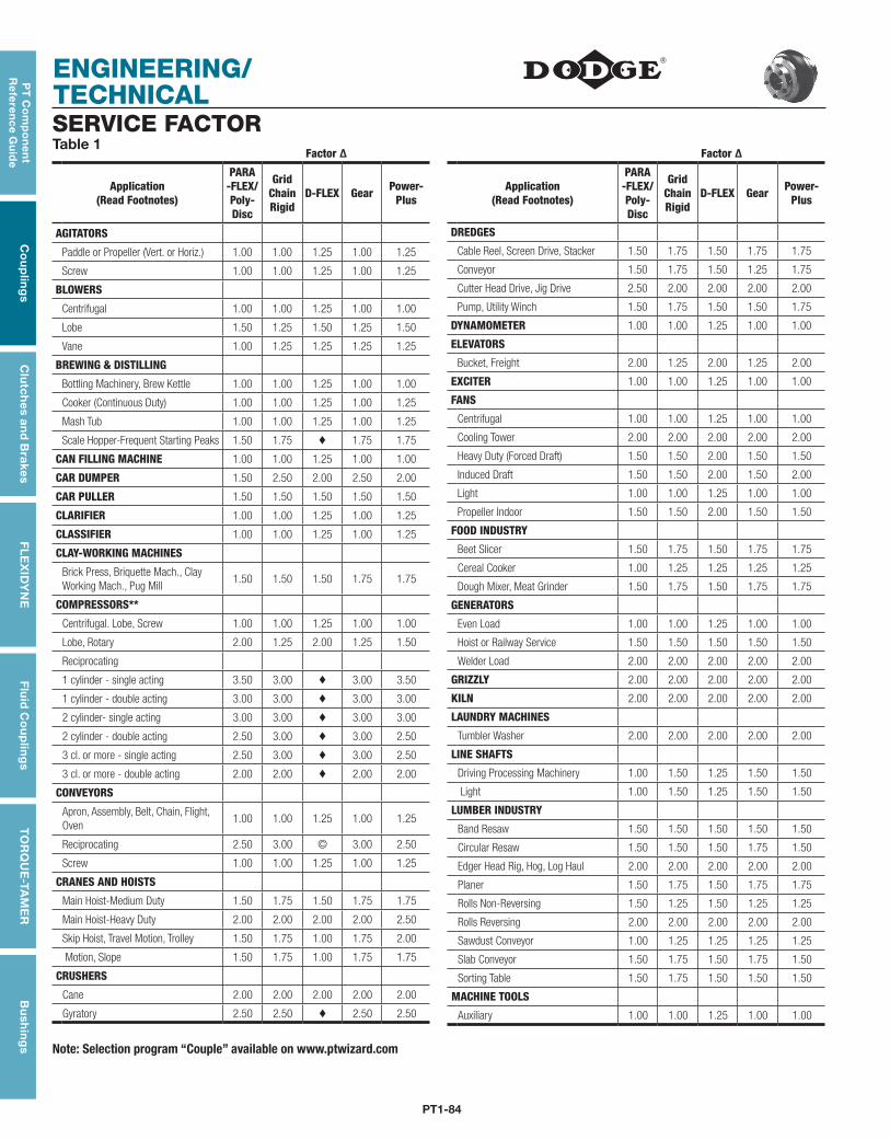
PT1-84
ENGINEERING/ TECHNICAL
PT
Co
mp
on
en
t R
efe
ren
ce G
uid
eC
ou
plin
gs
Clu
tch
es an
d B
rakesF
LE
XID
YN
EF
luid
Co
up
ling
sT
OR
QU
E-TA
ME
RB
ush
ing
s
Factor ∆
Application(Read Footnotes)
PARA -FLEX/Poly-Disc
Grid Chain Rigid
D-FLEX Gear Power- Plus
AGITATORS
Paddle or Propeller (Vert. or Horiz.) 1.00 1.00 1.25 1.00 1.25
Screw 1.00 1.00 1.25 1.00 1.25
BLOWERS
Centrifugal 1.00 1.00 1.25 1.00 1.00
Lobe 1.50 1.25 1.50 1.25 1.50
Vane 1.00 1.25 1.25 1.25 1.25
BREWING & DISTILLING
Bottling Machinery, Brew Kettle 1.00 1.00 1.25 1.00 1.00
Cooker (Continuous Duty) 1.00 1.00 1.25 1.00 1.25
Mash Tub 1.00 1.00 1.25 1.00 1.25
Scale Hopper-Frequent Starting Peaks 1.50 1.75 ♦ 1.75 1.75
CAN FILLING MACHINE 1.00 1.00 1.25 1.00 1.00
CAR DUMPER 1.50 2.50 2.00 2.50 2.00
CAR PULLER 1.50 1.50 1.50 1.50 1.50
CLARIFIER 1.00 1.00 1.25 1.00 1.25
CLASSIFIER 1.00 1.00 1.25 1.00 1.25
CLAY-WORKING MACHINES
Brick Press, Briquette Mach., Clay Working Mach., Pug Mill
1.50 1.50 1.50 1.75 1.75
COMPRESSORS**
Centrifugal. Lobe, Screw 1.00 1.00 1.25 1.00 1.00
Lobe, Rotary 2.00 1.25 2.00 1.25 1.50
Reciprocating
1 cylinder - single acting 3.50 3.00 ♦ 3.00 3.50
1 cylinder - double acting 3.00 3.00 ♦ 3.00 3.00
2 cylinder- single acting 3.00 3.00 ♦ 3.00 3.00
2 cylinder - double acting 2.50 3.00 ♦ 3.00 2.50
3 cl. or more - single acting 2.50 3.00 ♦ 3.00 2.50
3 cl. or more - double acting 2.00 2.00 ♦ 2.00 2.00
CONVEYORS
Apron, Assembly, Belt, Chain, Flight, Oven
1.00 1.00 1.25 1.00 1.25
Reciprocating 2.50 3.00 © 3.00 2.50
Screw 1.00 1.00 1.25 1.00 1.25
CRANES AND HOISTS
Main Hoist-Medium Duty 1.50 1.75 1.50 1.75 1.75
Main Hoist-Heavy Duty 2.00 2.00 2.00 2.00 2.50
Skip Hoist, Travel Motion, Trolley 1.50 1.75 1.00 1.75 2.00
Motion, Slope 1.50 1.75 1.00 1.75 1.75
CRUSHERS
Cane 2.00 2.00 2.00 2.00 2.00
Gyratory 2.50 2.50 ♦ 2.50 2.50
Factor ∆
Application(Read Footnotes)
PARA -FLEX/Poly-Disc
Grid Chain Rigid
D-FLEX Gear Power- Plus
DREDGES
Cable Reel, Screen Drive, Stacker 1.50 1.75 1.50 1.75 1.75
Conveyor 1.50 1.75 1.50 1.25 1.75
Cutter Head Drive, Jig Drive 2.50 2.00 2.00 2.00 2.00
Pump, Utility Winch 1.50 1.75 1.50 1.50 1.75
DYNAMOMETER 1.00 1.00 1.25 1.00 1.00
ELEVATORS
Bucket, Freight 2.00 1.25 2.00 1.25 2.00
EXCITER 1.00 1.00 1.25 1.00 1.00
FANS
Centrifugal 1.00 1.00 1.25 1.00 1.00
Cooling Tower 2.00 2.00 2.00 2.00 2.00
Heavy Duty (Forced Draft) 1.50 1.50 2.00 1.50 1.50
Induced Draft 1.50 1.50 2.00 1.50 2.00
Light 1.00 1.00 1.25 1.00 1.00
Propeller Indoor 1.50 1.50 2.00 1.50 1.50
FOOD INDUSTRY
Beet Slicer 1.50 1.75 1.50 1.75 1.75
Cereal Cooker 1.00 1.25 1.25 1.25 1.25
Dough Mixer, Meat Grinder 1.50 1.75 1.50 1.75 1.75
GENERATORS
Even Load 1.00 1.00 1.25 1.00 1.00
Hoist or Railway Service 1.50 1.50 1.50 1.50 1.50
Welder Load 2.00 2.00 2.00 2.00 2.00
GRIZZLY 2.00 2.00 2.00 2.00 2.00
KILN 2.00 2.00 2.00 2.00 2.00
LAUNDRY MACHINES
Tumbler Washer 2.00 2.00 2.00 2.00 2.00
LINE SHAFTS
Driving Processing Machinery 1.00 1.50 1.25 1.50 1.50
Light 1.00 1.50 1.25 1.50 1.50
LUMBER INDUSTRY
Band Resaw 1.50 1.50 1.50 1.50 1.50
Circular Resaw 1.50 1.50 1.50 1.75 1.50
Edger Head Rig, Hog, Log Haul 2.00 2.00 2.00 2.00 2.00
Planer 1.50 1.75 1.50 1.75 1.75
Rolls Non-Reversing 1.50 1.25 1.50 1.25 1.25
Rolls Reversing 2.00 2.00 2.00 2.00 2.00
Sawdust Conveyor 1.00 1.25 1.25 1.25 1.25
Slab Conveyor 1.50 1.75 1.50 1.75 1.50
Sorting Table 1.50 1.75 1.50 1.50 1.50
MACHINE TOOLS
Auxiliary 1.00 1.00 1.25 1.00 1.00
SERVICE FACTORTable 1
Note: Selection program “Couple” available on www.ptwizard.com
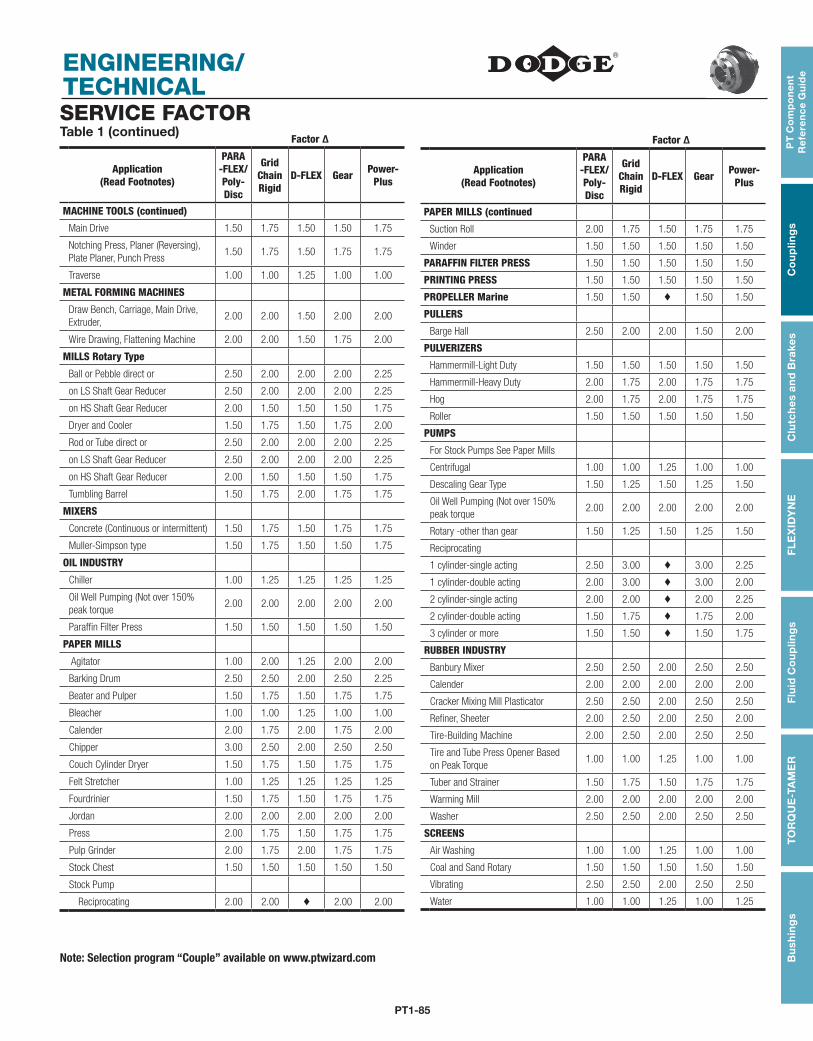
PT1-85
PT
Co
mp
on
en
t R
efe
ren
ce
Gu
ide
Co
up
ling
sC
lutc
hes
an
d B
rake
sF
LE
XID
YN
EF
luid
Co
up
ling
sT
OR
QU
E-T
AM
ER
Bu
shin
gs
ENGINEERING/ TECHNICAL
Factor ∆
Application(Read Footnotes)
PARA -FLEX/Poly-Disc
Grid Chain Rigid
D-FLEX Gear Power- Plus
MACHINE TOOLS (continued)
Main Drive 1.50 1.75 1.50 1.50 1.75
Notching Press, Planer (Reversing), Plate Planer, Punch Press
1.50 1.75 1.50 1.75 1.75
Traverse 1.00 1.00 1.25 1.00 1.00
METAL FORMING MACHINES
Draw Bench, Carriage, Main Drive, Extruder,
2.00 2.00 1.50 2.00 2.00
Wire Drawing, Flattening Machine 2.00 2.00 1.50 1.75 2.00
MILLS Rotary Type
Ball or Pebble direct or 2.50 2.00 2.00 2.00 2.25
on LS Shaft Gear Reducer 2.50 2.00 2.00 2.00 2.25
on HS Shaft Gear Reducer 2.00 1.50 1.50 1.50 1.75
Dryer and Cooler 1.50 1.75 1.50 1.75 2.00
Rod or Tube direct or 2.50 2.00 2.00 2.00 2.25
on LS Shaft Gear Reducer 2.50 2.00 2.00 2.00 2.25
on HS Shaft Gear Reducer 2.00 1.50 1.50 1.50 1.75
Tumbling Barrel 1.50 1.75 2.00 1.75 1.75
MIXERS
Concrete (Continuous or intermittent) 1.50 1.75 1.50 1.75 1.75
Muller-Simpson type 1.50 1.75 1.50 1.50 1.75
OIL INDUSTRY
Chiller 1.00 1.25 1.25 1.25 1.25
Oil Well Pumping (Not over 150% peak torque
2.00 2.00 2.00 2.00 2.00
Paraffin Filter Press 1.50 1.50 1.50 1.50 1.50
PAPER MILLS
Agitator 1.00 2.00 1.25 2.00 2.00
Barking Drum 2.50 2.50 2.00 2.50 2.25
Beater and Pulper 1.50 1.75 1.50 1.75 1.75
Bleacher 1.00 1.00 1.25 1.00 1.00
Calender 2.00 1.75 2.00 1.75 2.00
Chipper 3.00 2.50 2.00 2.50 2.50
Couch Cylinder Dryer 1.50 1.75 1.50 1.75 1.75
Felt Stretcher 1.00 1.25 1.25 1.25 1.25
Fourdrinier 1.50 1.75 1.50 1.75 1.75
Jordan 2.00 2.00 2.00 2.00 2.00
Press 2.00 1.75 1.50 1.75 1.75
Pulp Grinder 2.00 1.75 2.00 1.75 1.75
Stock Chest 1.50 1.50 1.50 1.50 1.50
Stock Pump
Reciprocating 2.00 2.00 ♦ 2.00 2.00
SERVICE FACTORTable 1 (continued)
Factor ∆
Application(Read Footnotes)
PARA -FLEX/Poly-Disc
Grid Chain Rigid
D-FLEX Gear Power- Plus
PAPER MILLS (continued
Suction Roll 2.00 1.75 1.50 1.75 1.75
Winder 1.50 1.50 1.50 1.50 1.50
PARAFFIN FILTER PRESS 1.50 1.50 1.50 1.50 1.50
PRINTING PRESS 1.50 1.50 1.50 1.50 1.50
PROPELLER Marine 1.50 1.50 ♦ 1.50 1.50
PULLERS
Barge Hall 2.50 2.00 2.00 1.50 2.00
PULVERIZERS
Hammermill-Light Duty 1.50 1.50 1.50 1.50 1.50
Hammermill-Heavy Duty 2.00 1.75 2.00 1.75 1.75
Hog 2.00 1.75 2.00 1.75 1.75
Roller 1.50 1.50 1.50 1.50 1.50
PUMPS
For Stock Pumps See Paper Mills
Centrifugal 1.00 1.00 1.25 1.00 1.00
Descaling Gear Type 1.50 1.25 1.50 1.25 1.50
Oil Well Pumping (Not over 150% peak torque
2.00 2.00 2.00 2.00 2.00
Rotary -other than gear 1.50 1.25 1.50 1.25 1.50
Reciprocating
1 cylinder-single acting 2.50 3.00 ♦ 3.00 2.25
1 cylinder-double acting 2.00 3.00 ♦ 3.00 2.00
2 cylinder-single acting 2.00 2.00 ♦ 2.00 2.25
2 cylinder-double acting 1.50 1.75 ♦ 1.75 2.00
3 cylinder or more 1.50 1.50 ♦ 1.50 1.75
RUBBER INDUSTRY
Banbury Mixer 2.50 2.50 2.00 2.50 2.50
Calender 2.00 2.00 2.00 2.00 2.00
Cracker Mixing Mill Plasticator 2.50 2.50 2.00 2.50 2.50
Refiner, Sheeter 2.00 2.50 2.00 2.50 2.00
Tire-Building Machine 2.00 2.50 2.00 2.50 2.50
Tire and Tube Press Opener Based on Peak Torque
1.00 1.00 1.25 1.00 1.00
Tuber and Strainer 1.50 1.75 1.50 1.75 1.75
Warming Mill 2.00 2.00 2.00 2.00 2.00
Washer 2.50 2.50 2.00 2.50 2.50
SCREENS
Air Washing 1.00 1.00 1.25 1.00 1.00
Coal and Sand Rotary 1.50 1.50 1.50 1.50 1.50
Vibrating 2.50 2.50 2.00 2.50 2.50
Water 1.00 1.00 1.25 1.00 1.25
Note: Selection program “Couple” available on www.ptwizard.com
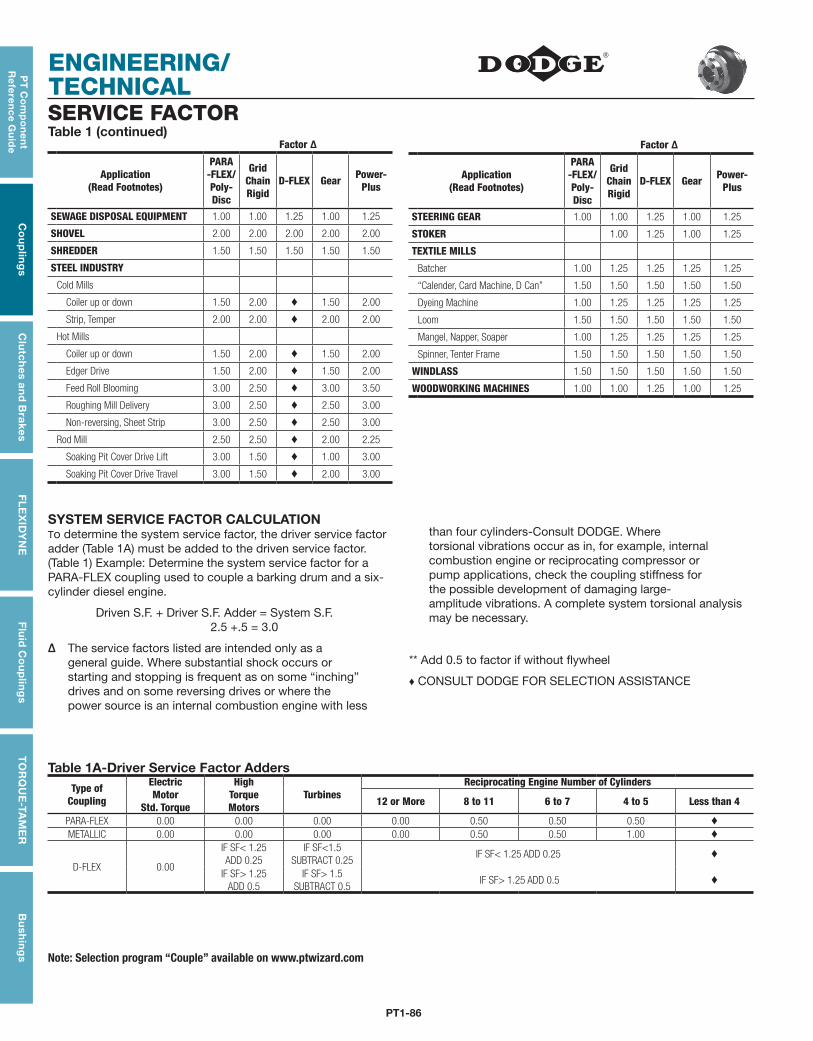
PT1-86
ENGINEERING/ TECHNICAL
PT
Co
mp
on
en
t R
efe
ren
ce G
uid
eC
ou
plin
gs
Clu
tch
es an
d B
rakesF
LE
XID
YN
EF
luid
Co
up
ling
sT
OR
QU
E-TA
ME
RB
ush
ing
s
SYSTEM SERVICE FACTOR CALCULATIONTo determine the system service factor, the driver service fac tor adder (Table 1A) must be added to the driven service factor. (Table 1) Example: Determine the system service factor for a PARA-FLEX coupling used to couple a barking drum and a six-cylinder diesel engine.
Driven S.F. + Driver S.F. Adder = System S.F. 2.5 +.5 = 3.0
∆ The service factors listed are intended only as a general guide. Where substantial shock occurs or starting and stopping is frequent as on some “inching” drives and on some reversing drives or where the power source is an internal combustion engine with less
than four cylinders-Consult DODGE. Where torsional vibrations occur as in, for example, internal combustion engine or reciprocating compressor or pump applications, check the coupling stiff ness for the possible development of damaging large- amplitude vibrations. A complete system torsional analysis may be necessary.
** Add 0.5 to factor if without flywheel
♦ CONSULT DODGE FOR SELECTION ASSISTANCE
Table 1A-Driver Service Factor AddersType of
Coupling
ElectricMotor
Std. Torque
HighTorque Motors
TurbinesReciprocating Engine Number of Cylinders
12 or More 8 to 11 6 to 7 4 to 5 Less than 4
PARA-FLEX 0.00 0.00 0.00 0.00 0.50 0.50 0.50 ♦
METALLIC 0.00 0.00 0.00 0.00 0.50 0.50 1.00 ♦
D-FLEX 0.00
IF SF< 1.25ADD 0.25
IF SF<1.5SUBTRACT 0.25
IF SF< 1.25 ADD 0.25 ♦
IF SF> 1.25ADD 0.5
IF SF> 1.5SUBTRACT 0.5
IF SF> 1.25 ADD 0.5 ♦
Factor ∆
Application(Read Footnotes)
PARA -FLEX/Poly-Disc
Grid Chain Rigid
D-FLEX Gear Power- Plus
SEWAGE DISPOSAL EQUIPMENT 1.00 1.00 1.25 1.00 1.25
SHOVEL 2.00 2.00 2.00 2.00 2.00
SHREDDER 1.50 1.50 1.50 1.50 1.50
STEEL INDUSTRY
Cold Mills
Coiler up or down 1.50 2.00 ♦ 1.50 2.00
Strip, Temper 2.00 2.00 ♦ 2.00 2.00
Hot Mills
Coiler up or down 1.50 2.00 ♦ 1.50 2.00
Edger Drive 1.50 2.00 ♦ 1.50 2.00
Feed Roll Blooming 3.00 2.50 ♦ 3.00 3.50
Roughing Mill Delivery 3.00 2.50 ♦ 2.50 3.00
Non-reversing, Sheet Strip 3.00 2.50 ♦ 2.50 3.00
Rod Mill 2.50 2.50 ♦ 2.00 2.25
Soaking Pit Cover Drive Lift 3.00 1.50 ♦ 1.00 3.00
Soaking Pit Cover Drive Travel 3.00 1.50 ♦ 2.00 3.00
SERVICE FACTORTable 1 (continued)
Factor ∆
Application(Read Footnotes)
PARA -FLEX/Poly-Disc
Grid Chain Rigid
D-FLEX Gear Power- Plus
STEERING GEAR 1.00 1.00 1.25 1.00 1.25
STOKER 1.00 1.25 1.00 1.25
TEXTILE MILLS
Batcher 1.00 1.25 1.25 1.25 1.25
“Calender, Card Machine, D Can” 1.50 1.50 1.50 1.50 1.50
Dyeing Machine 1.00 1.25 1.25 1.25 1.25
Loom 1.50 1.50 1.50 1.50 1.50
Mangel, Napper, Soaper 1.00 1.25 1.25 1.25 1.25
Spinner, Tenter Frame 1.50 1.50 1.50 1.50 1.50
WINDLASS 1.50 1.50 1.50 1.50 1.50
WOODWORKING MACHINES 1.00 1.00 1.25 1.00 1.25
Note: Selection program “Couple” available on www.ptwizard.com
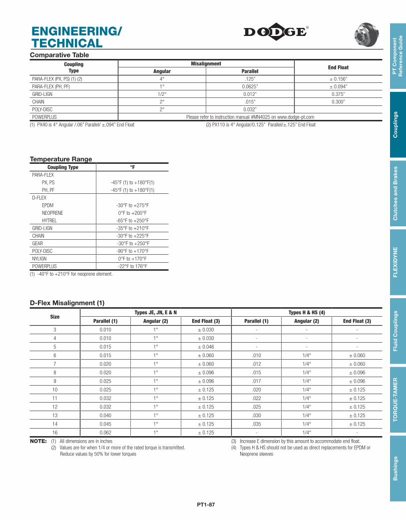
PT1-87
PT
Co
mp
on
en
t R
efe
ren
ce
Gu
ide
Co
up
ling
sC
lutc
hes
an
d B
rake
sF
LE
XID
YN
EF
luid
Co
up
ling
sT
OR
QU
E-T
AM
ER
Bu
shin
gs
ENGINEERING/ TECHNICAL
SizeTypes JE, JN, E & N Types H & HS (4)
Parallel (1) Angular (2) End Float (3) Parallel (1) Angular (2) End Float (3)
3 0.010 1° ± 0.030 - - -
4 0.010 1° ± 0.030 - - -
5 0.015 1° ± 0.046 - - -
6 0.015 1° ± 0.060 .010 1/4° ± 0.060
7 0.020 1° ± 0.060 .012 1/4° ± 0.060
8 0.020 1° ± 0.096 .015 1/4° ± 0.096
9 0.025 1° ± 0.096 .017 1/4° ± 0.096
10 0.025 1° ± 0.125 .020 1/4° ± 0.125
11 0.032 1° ± 0.125 .022 1/4° ± 0.125
12 0.032 1° ± 0.125 .025 1/4° ± 0.125
13 0.040 1° ± 0.125 .030 1/4° ± 0.125
14 0.045 1° ± 0.125 .035 1/4° ± 0.125
16 0.062 1° ± 0.125 - 1/4° -
NOTE: (1) All dimensions are in inches (2) Values are for when 1/4 or more of the rated torque is transmitted. Reduce values by 50% for lower torques
(3) Increase E dimension by this amount to accommodate end float.(4) Types H & HS should not be used as direct replacements for EPDM or Neoprene sleeves
D-Flex Misalignment (1)
Temperature RangeCoupling Type °F
PARA-FLEX
PX, PS -45°F (1) to +180°F(1)
PH, PF -45°F (1) to +180°F(1)
D-FLEX
EPDM -30°F to +275°F
NEOPRENE 0°F to +200°F
HYTREL -65°F to +250°F
GRID-LIGN -35°F to +210°F
CHAIN -30°F to +225°F
GEAR -30°F to +250°F
POLY-DISC -90°F to +170°F
NYLIGN 0°F to +170°F
POWERPLUS -22°F to 176°F
(1) -40°F to +210°F for neoprene element.
CouplingType
MisalignmentEnd Float
Angular ParallelPARA-FLEX (PX, PS) (1) (2) 4° .125” ± 0.156”
PARA-FLEX (PH, PF) 1° 0.0625” ± 0.094”
GRID-LIGN 1/2° 0.012” 0.375”
CHAIN 2° .015” 0.300”
POLY-DISC 2° 0.032”
POWERPLUS Please refer to instruction manual #MN4025 on www.dodge-pt.com
(1) PX40 is 4° Angular /.06” Parallel/ ±.094” End Float (2) PX110 is 4° Angular/0.125” Parallel/±.125” End Float
Comparative Table
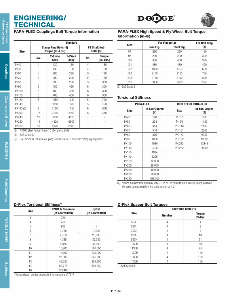
PT1-88
ENGINEERING/ TECHNICAL
PT
Co
mp
on
en
t R
efe
ren
ce G
uid
eC
ou
plin
gs
Clu
tch
es an
d B
rakesF
LE
XID
YN
EF
luid
Co
up
ling
sT
OR
QU
E-TA
ME
RB
ush
ing
s
PARA-FLEX Couplings Bolt Torque Information PARA-FLEX High Speed & Fly Wheel Bolt Torque Information (in-lb)
Size
StandardSize
For Flange (3) For Bolt Ring(3)Clamp Ring Bolts (5)
Torque (In.-Lbs.)PS Shaft Hub
Bolts (3)Iron Fig. Steel Fig.
87 290 290 180
No. 2-PieceAssy
3-PieceAssy No. Torque
(In.-Lbs.)96 290 290 300
116 480 480 360
PX40 4 130 130 4 130 131 480 480 420
PX50 5 130 130 4 180 172 1080 1150 600
PX60 5 290 290 5 180 192 2160 1150 780
PX70 5 290 290 5 180 213 2160 2160 840
PX80 6 290 290 5 300 252 3600 3600 2880
PX90 6 480 480 6 300 (3) SAE Grade 8
PX100 6 480 480 6 300
PX110 6 480 480 6 300Torsional Stiffness
PX120 6 1080 1080 6 720
PX140 8 1080 1080 5 720 PARA-FLEX HIGH SPEED PARA-FLEXPX160 (2) 8 2160 1150 6 1296
Size In-Lbs/Degree (4) Size In-Lbs/Degree
(4)PX200 12 2160 2400 8 1296
PX240 12 3600 4020 - - PX40 120 PH 87 1000
PX280 14 4320 6600 - - PX50 224 PH 96 1190
PX320 16 4320 6600 - - PX60 414 PH 116 2182
(2) PX160 steel flanges have 10 clamp ring bolts PX70 544 PH 131 2566
(3) SAE Grade 8 PX80 876 PH 172 6737
(5) SAE Grade 8. FB style couplings utilize class 10.9 metric clamping ring bolts PX90 1088 PH 192 13893
PX100 1530 PH 213 23143
PX110 2420 PH 252 39008
PX120 4014
PX140 8296
PX160 12,000
PX200 29,000
PX240 48,000
PX280 98,000
PX320 151,000
(4) Values are nominal and may vary +/- 20%. To convert static values to approximate dynamic values, multiply the static values by 1.2
D-Flex Torsional Stiffness* D-Flex Spacer Bolt Torques
Size EPDM & Neoprene(In-Lbs/radian)
Hytrel(In-Lbs/radian) Size
Shaft Hub Bolts (1)
Number TorqueFt-Lbs3 229 -
4 458 - 5SCH 4 4
5 916 - 6SCH 4 9
6 1,718 10,000 7SCH 4 9
7 2,769 20,000 8SCH 4 18
8 4,335 30,000 9SCH 4 31
9 6,875 47,500 10SCH 4 50
10 10,980 100,000 11SCH 4 75
11 17,300 125,000 12SCH 4 150
12 27,500 225,000 13SCH 4 150
13 43,350 368,900 14SCH 4 150
14 68,775 593,250 (1) SAE Grade 8
16 180,480 -
* Values shown are for an ambient temperature of 75°F
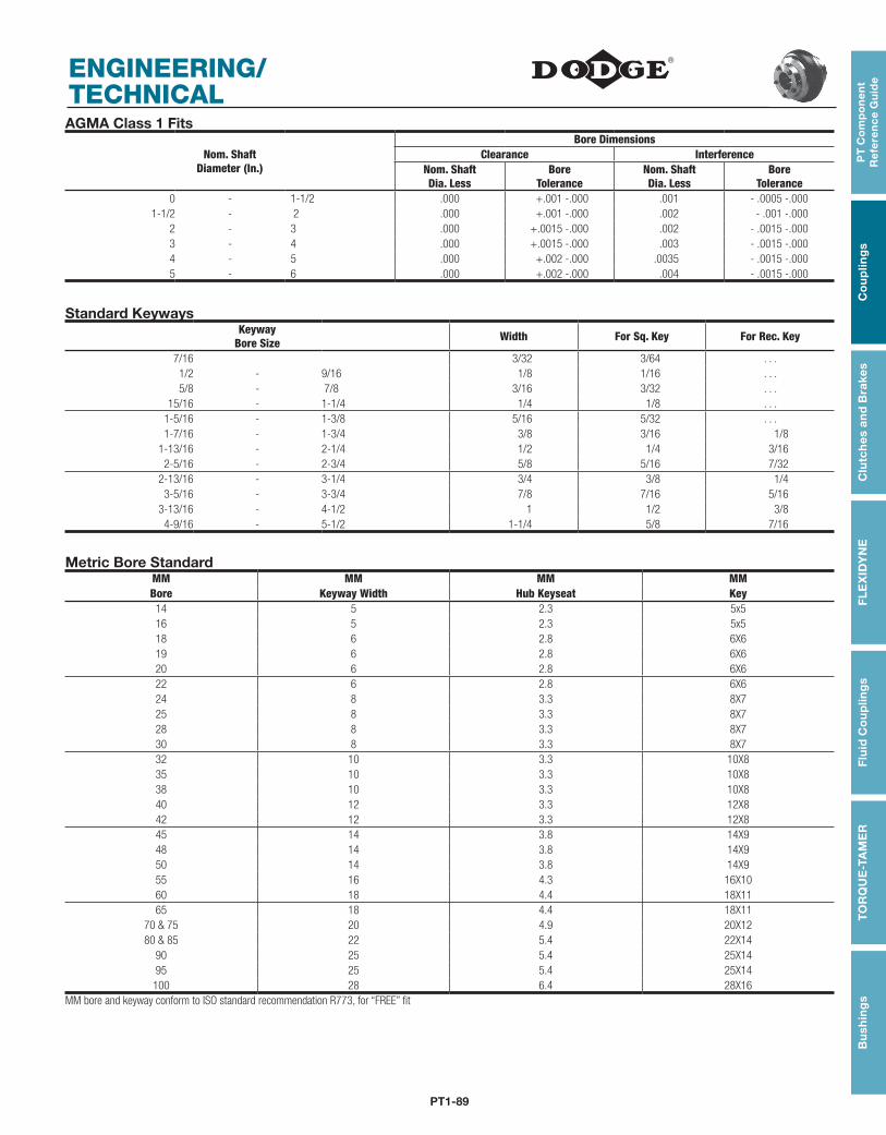
PT1-89
PT
Co
mp
on
en
t R
efe
ren
ce
Gu
ide
Co
up
ling
sC
lutc
hes
an
d B
rake
sF
LE
XID
YN
EF
luid
Co
up
ling
sT
OR
QU
E-T
AM
ER
Bu
shin
gs
ENGINEERING/ TECHNICALAGMA Class 1 Fits
Nom. ShaftDiameter (In.)
Bore DimensionsClearance Interference
Nom. ShaftDia. Less
BoreTolerance
Nom. ShaftDia. Less
BoreTolerance
0 - 1-1/2 .000 +.001 -.000 .001 - .0005 -.0001-1/2 - 2 .000 +.001 -.000 .002 - .001 -.000
2 - 3 .000 +.0015 -.000 .002 - .0015 -.0003 - 4 .000 +.0015 -.000 .003 - .0015 -.0004 - 5 .000 +.002 -.000 .0035 - .0015 -.0005 - 6 .000 +.002 -.000 .004 - .0015 -.000
Standard KeywaysKeyway
Bore Size Width For Sq. Key For Rec. Key
7/16 3/32 3/64 . . .1/2 - 9/16 1/8 1/16 . . .5/8 - 7/8 3/16 3/32 . . .
15/16 - 1-1/4 1/4 1/8 . . .1-5/16 - 1-3/8 5/16 5/32 . . .1-7/16 - 1-3/4 3/8 3/16 1/8
1-13/16 - 2-1/4 1/2 1/4 3/162-5/16 - 2-3/4 5/8 5/16 7/32
2-13/16 - 3-1/4 3/4 3/8 1/43-5/16 - 3-3/4 7/8 7/16 5/16
3-13/16 - 4-1/2 1 1/2 3/84-9/16 - 5-1/2 1-1/4 5/8 7/16
Metric Bore StandardMM MM MM MM Bore Keyway Width Hub Keyseat Key14 5 2.3 5x516 5 2.3 5x518 6 2.8 6X619 6 2.8 6X620 6 2.8 6X622 6 2.8 6X624 8 3.3 8X725 8 3.3 8X728 8 3.3 8X730 8 3.3 8X732 10 3.3 10X835 10 3.3 10X838 10 3.3 10X840 12 3.3 12X842 12 3.3 12X845 14 3.8 14X948 14 3.8 14X950 14 3.8 14X955 16 4.3 16X1060 18 4.4 18X1165 18 4.4 18X11
70 & 75 20 4.9 20X1280 & 85 22 5.4 22X14
90 25 5.4 25X1495 25 5.4 25X14100 28 6.4 28X16
MM bore and keyway conform to ISO standard recommendation R773, for “FREE” fit
PT1-90
NOTESPT
Co
mp
on
en
t R
efe
ren
ce G
uid
eC
ou
plin
gs
Clu
tch
es an
d B
rakesF
LE
XID
YN
EF
luid
Co
up
ling
sT
OR
QU
E-TA
ME
RB
ush
ing