pstn/isdn emulation and ims/ngn reference benchmarking...• call flow • load profile • metrics...
TRANSCRIPT
PSTN/ISDN emulation and IMS/NGN Reference Benchmarking
Martin Brand
Vice Chairman of ETSI TC INT, Rapporteur of Q11/11 and Co-Rapporteur of Q2/11
• Why is IMS Benchmarking needed
• History
• Benchmark Development Process
• Benchmark Information Model
• Use-case
• Call flow
• Load profile
• Metrics and design objectives
• Benchmark Test
• Benchmark report
• Q.3933 “Reference benchmarking, background traffic profiles and KPIs for VoIP and FoIP in fixed networks”
2
Presentation Outline
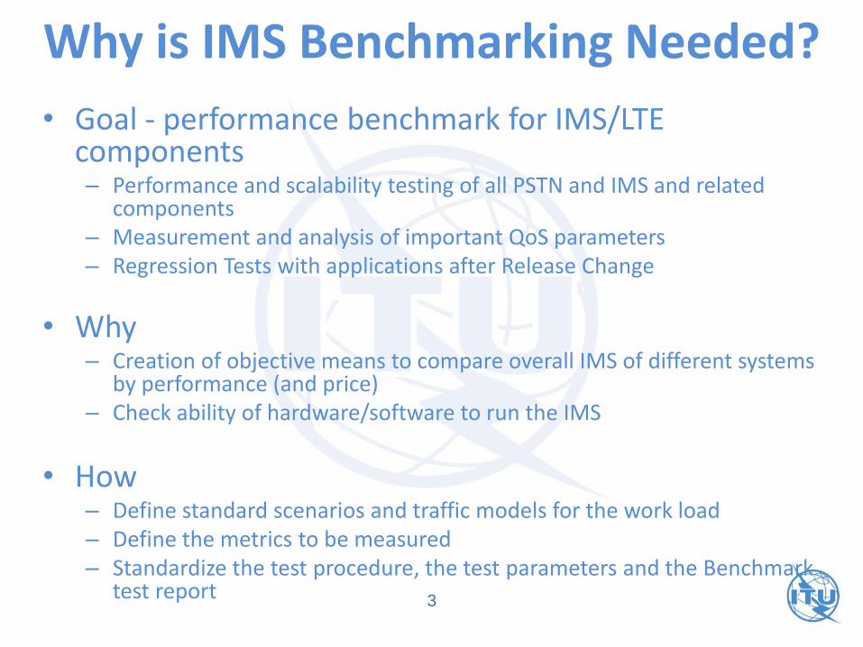
• Goal - performance benchmark for IMS/LTE components– Performance and scalability testing of all PSTN and IMS and related
components– Measurement and analysis of important QoS parameters– Regression Tests with applications after Release Change
• Why – Creation of objective means to compare overall IMS of different systems
by performance (and price)– Check ability of hardware/software to run the IMS
• How– Define standard scenarios and traffic models for the work load– Define the metrics to be measured– Standardize the test procedure, the test parameters and the Benchmark
test report
Why is IMS Benchmarking Needed?
3
History
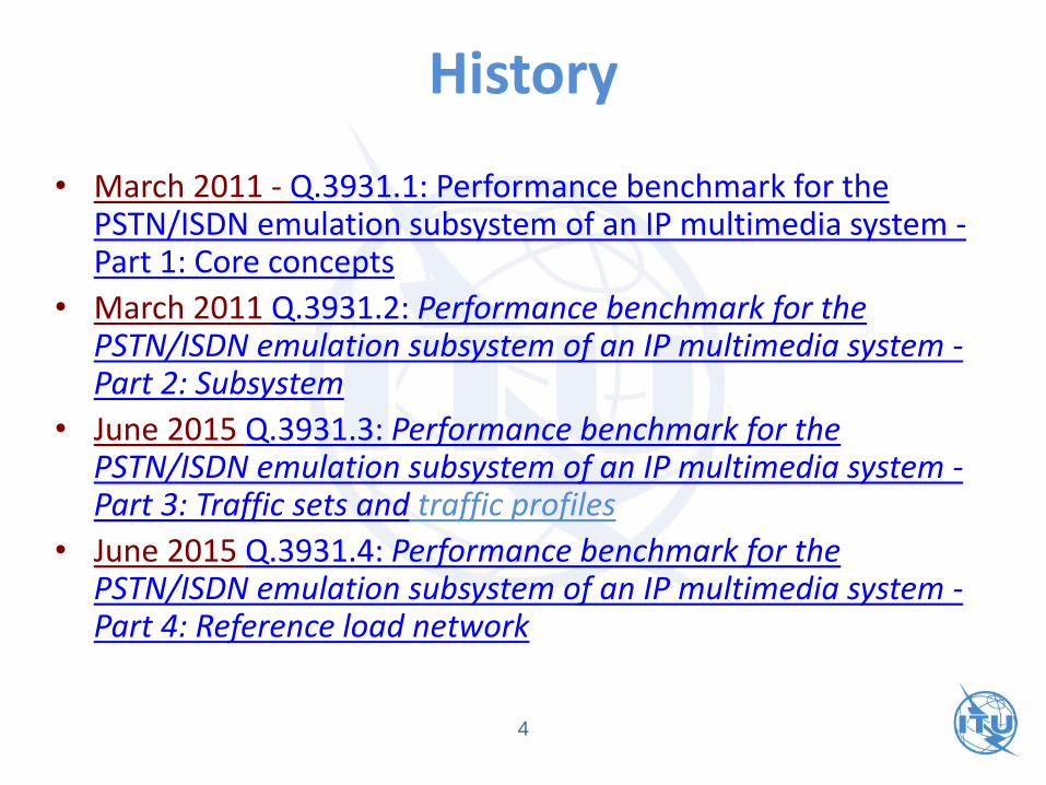
• March 2011 - Q.3931.1: Performance benchmark for the PSTN/ISDN emulation subsystem of an IP multimedia system -Part 1: Core concepts
• March 2011 Q.3931.2: Performance benchmark for the PSTN/ISDN emulation subsystem of an IP multimedia system -Part 2: Subsystem
• June 2015 Q.3931.3: Performance benchmark for the PSTN/ISDN emulation subsystem of an IP multimedia system -Part 3: Traffic sets and traffic profiles
• June 2015 Q.3931.4: Performance benchmark for the PSTN/ISDN emulation subsystem of an IP multimedia system -Part 4: Reference load network
4
History
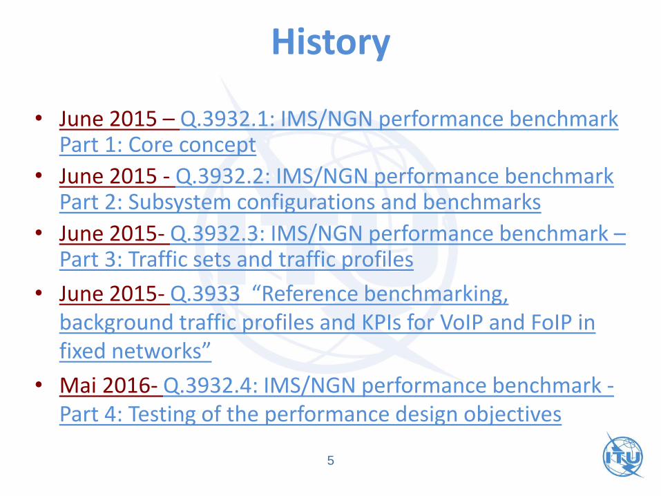
• June 2015 – Q.3932.1: IMS/NGN performance benchmarkPart 1: Core concept
• June 2015 - Q.3932.2: IMS/NGN performance benchmark Part 2: Subsystem configurations and benchmarks
• June 2015- Q.3932.3: IMS/NGN performance benchmark –Part 3: Traffic sets and traffic profiles
• June 2015- Q.3933 “Reference benchmarking, background traffic profiles and KPIs for VoIP and FoIP in fixed networks”
• Mai 2016- Q.3932.4: IMS/NGN performance benchmark -Part 4: Testing of the performance design objectives
5
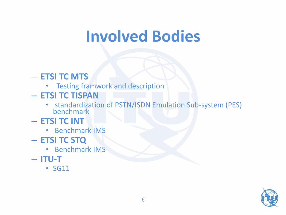
Involved Bodies
– ETSI TC MTS • Testing framwork and description
– ETSI TC TISPAN• standardization of PSTN/ISDN Emulation Sub-system (PES)
benchmark
– ETSI TC INT• Benchmark IMS
– ETSI TC STQ • Benchmark IMS
– ITU-T • SG11
6
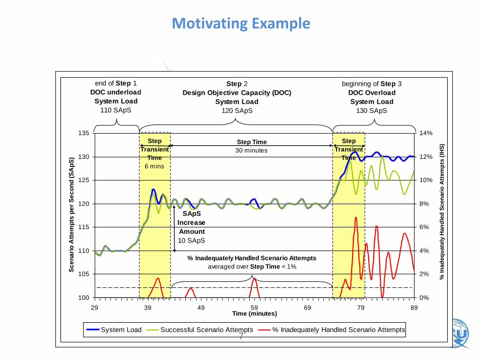
Motivating Example
100
105
110
115
120
125
130
135
29 39 49 59 69 79 89Time (minutes)
Sc
en
ari
o A
tte
mp
ts p
er
Se
co
nd
(S
Ap
S)
0%
2%
4%
6%
8%
10%
12%
14%
% In
ad
eq
uate
ly H
an
dle
d S
cen
ari
o A
ttem
pts
(IH
S)
System Load Successful Scenario Attempts % Inadequately Handled Scenario Attempts
% Inadequately Handled Scenario Attempts
averaged over Step Time < 1%
Step
Transient
Time
6 mins
Step
Transient
Time
Step Time
30 minutes
SApS
Increase
Amount
10 SApS
end of Step 1
DOC underload
System Load
110 SApS
Step 2
Design Objective Capacity (DOC)
System Load
120 SApS
beginning of Step 3
DOC Overload
System Load
130 SApS
7

Scope of IMS/LTE Performance Benchmarking
8
IMS UA
MME
S-GW
HSS
P-CSCF
IMS-ALG
IMS-AGW
P-GW
PCRF
UE
eNodeB
IMS Core
LTE-UuS11
S5
Gx
SGi
Rx
S6a
S1-MME
S1-U
IMS UA
UE
I/S-CSCF
MMTel AS
Sh
Mw
I
S
CCx
UtUt
Gm
Mb
Mb
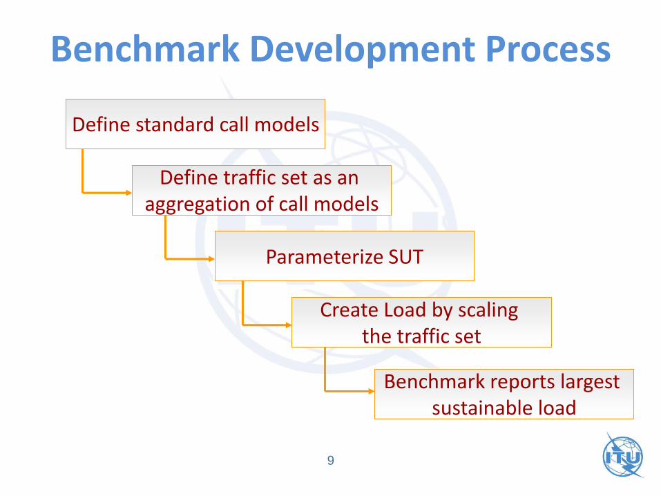
Benchmark Development Process
9
Define standard call models
Define traffic set as an aggregation of call models
Parameterize SUT
Create Load by scaling the traffic set
Benchmark reports largest sustainable load
Use-case
• The top level of the individual behavioural model is the use-case. A use-case describes the goal that a user has in interacting with a system
10
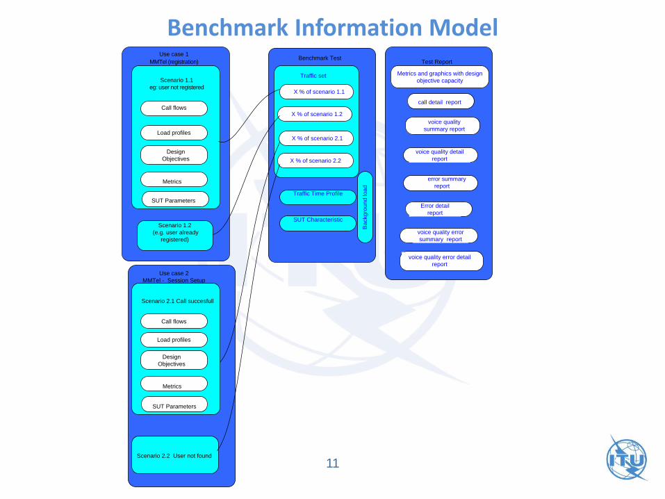
Benchmark Information Model
11
Scenario 1.1
eg: user not registered
Metrics
Design
Objectives
Call flows
Scenario 1.2
(e.g. user already
registered)
X % of scenario 1.1
X % of scenario 1.2
X % of scenario 2.1
X % of scenario 2.2
call detail report
voice quality
summary report
voice quality detail
report
error summary
report
Error detail
report
voice quality error
summary report
voice quality error detail
report
Load profiles
Metrics
Call flows
Load profiles
Scenario 2.1 Call succesfull
Scenario 2.2 User not found
Traffic set
Test ReportBenchmark Test
Use case 1 MMTel (registration)
Use case 2
MMTel - Session Setup
Metrics and graphics with design
objective capacity
SUT Parameters
Design
Objectives
SUT Parameters
Traffic Time Profile
SUT Characteristic
Ba
ckg
rou
nd
lo
ad

IMS/LTE Use Cases• IMS/PES to IMS/PES
• Registration/de-registration use-case
• MMTel to MMTel Use case
• ISDN to MMTel Use case
• MMTel to ISDN Use case
• MMTel to PSTN Use case
• PSTN to MMTEL Use case
• ISDN to VoLTE Use case
• VoLTE to ISDN Use case
• VoLTE – PSTN Use case
• PSTN to VoLTE Use case
• VoLTE to VoLTE Use case
• VoLTE to MMTel Use case
• MMTel to VoLTE Use case
12

IMS/LTE Scenario Example: IMS Call
13

Call flow example IMS/PES environment calling side
14
OFF Hook
On Hook
Timer T1
Test Fail
Send digits
Ringing
Tone
Available
No
Yes
Start Timer
T2
Waiting for
ringing ton
Start
Timer T3
Waiting for
answer
T3 time
out
Timer T4
Connection
Holding time
Yes
Yes
STOP Timer
T2
Timer T2
Waiting for
ALERTING
timeout
Yes
Connection
Established
Stop timer T3
Yes
No
No
No
Dialing tone
Available
No timer local exchange
call request delay timeout
Yes
1
1
1
1
Start timer local exchange
call request delay
Yes
No
2
STOP Timer call request
delay
Send Voice
Samples
Receive
Voice Samples
Inband
Synch
Establi
shed
T4 time
out
DTMF
Send inband
digits
Receive inband
digits
PESQ
> limit
Yes
Yes
No
Yes
2
1
Stop T4
Test PassSTOP Timer
T2
Yes
No
No
1
Stop T4
Stop T1
Calling party

Load profiles example
15
2.6666.. CAPS
0
5
10
15
20
25
30
35
40
45
0 5 10 15 20 25 30
Seconds
Use
r
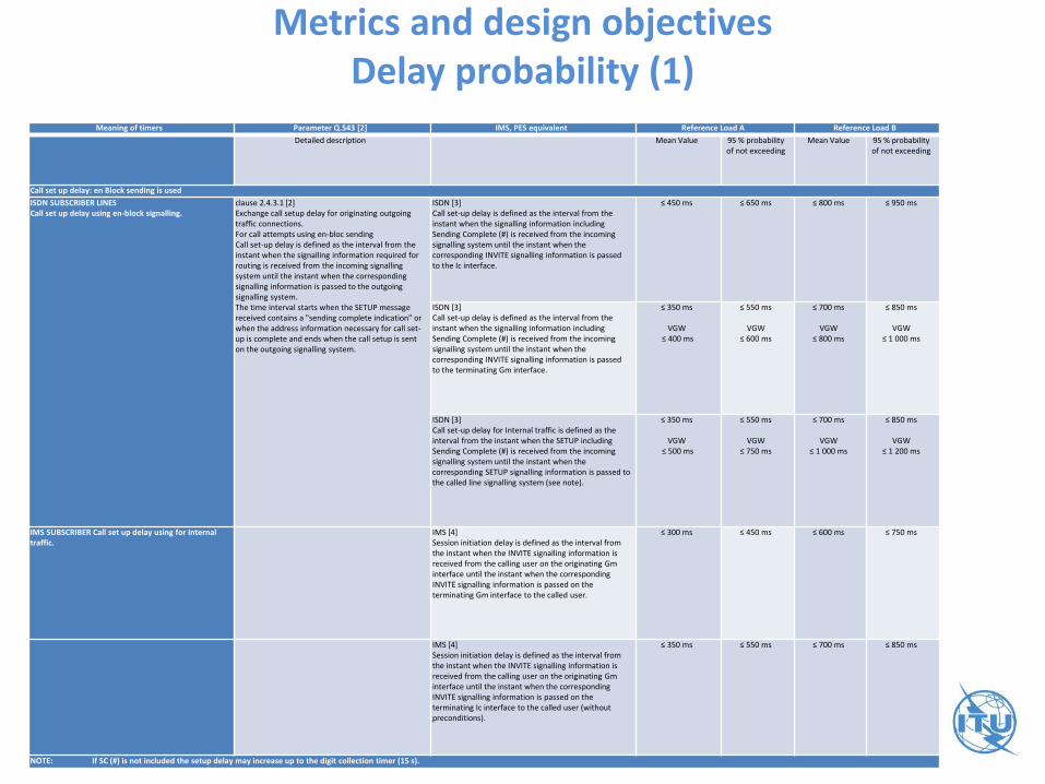
Metrics and design objectivesDelay probability (1)
16
Meaning of timers Parameter Q.543 [2] IMS, PES equivalent Reference Load A Reference Load B
Detailed description Mean Value 95 % probability of not exceeding
Mean Value 95 % probability of not exceeding
Call set up delay: en Block sending is used
ISDN SUBSCRIBER LINES Call set up delay using en-block signalling.
clause 2.4.3.1 [2]Exchange call setup delay for originating outgoing traffic connections. For call attempts using en-bloc sendingCall set-up delay is defined as the interval from the instant when the signalling information required for routing is received from the incoming signalling system until the instant when the corresponding signalling information is passed to the outgoing signalling system.The time interval starts when the SETUP message received contains a "sending complete indication" or when the address information necessary for call set-up is complete and ends when the call setup is sent on the outgoing signalling system.
ISDN [3]Call set-up delay is defined as the interval from the instant when the signalling information including Sending Complete (#) is received from the incoming signalling system until the instant when the corresponding INVITE signalling information is passed to the Ic interface.
≤ 450 ms ≤ 650 ms ≤ 800 ms ≤ 950 ms
ISDN [3]Call set-up delay is defined as the interval from the instant when the signalling information including Sending Complete (#) is received from the incoming signalling system until the instant when the corresponding INVITE signalling information is passed to the terminating Gm interface.
≤ 350 ms
VGW ≤ 400 ms
≤ 550 ms
VGW≤ 600 ms
≤ 700 ms
VGW ≤ 800 ms
≤ 850 ms
VGW ≤ 1 000 ms
ISDN [3]Call set-up delay for Internal traffic is defined as the interval from the instant when the SETUP including Sending Complete (#) is received from the incoming signalling system until the instant when the corresponding SETUP signalling information is passed to the called line signalling system (see note).
≤ 350 ms
VGW ≤ 500 ms
≤ 550 ms
VGW≤ 750 ms
≤ 700 ms
VGW ≤ 1 000 ms
≤ 850 ms
VGW ≤ 1 200 ms
IMS SUBSCRIBER Call set up delay using for Internal traffic.
IMS [4]Session initiation delay is defined as the interval from the instant when the INVITE signalling information is received from the calling user on the originating Gm interface until the instant when the corresponding INVITE signalling information is passed on the terminating Gm interface to the called user.
≤ 300 ms ≤ 450 ms ≤ 600 ms ≤ 750 ms
IMS [4]Session initiation delay is defined as the interval from the instant when the INVITE signalling information is received from the calling user on the originating Gm interface until the instant when the corresponding INVITE signalling information is passed on the terminating Ic interface to the called user (without preconditions).
≤ 350 ms ≤ 550 ms ≤ 700 ms ≤ 850 ms
NOTE: If SC (#) is not included the setup delay may increase up to the digit collection timer (15 s).
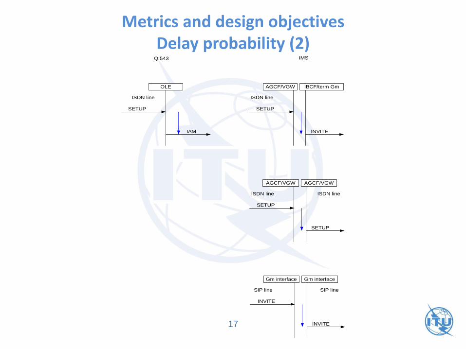
Metrics and design objectivesDelay probability (2)
17
OLE
IAM
SETUP
AGCF/VGW
SETUP
ISDN line ISDN line
Q.543 IMS
INVITE
IBCF/term Gm
AGCF/VGW
SETUP
ISDN line
SETUP
AGCF/VGW
ISDN line
Gm interface
INVITE
SIP line
INVITE
Gm interface
SIP line

Traffic Set Example
Use Case
Section
Test Scenario Scenario % of
System Load
Scenario
Arrival
Distribution
Scenario
Duration
Distribution
Use case 1 Scenario1.1 20 % Poisson Mean = 110 sec
Scenario 1.2 20 % Poisson Mean = 110 sec
Use case 2 Scenario 2.1 15 % Poisson Mean = 90 sec
Scenario 2.2 15 % Poisson Mean = 90 sec
Use case 3 Scenario 3.1 15% Poisson Mean = 90 sec
Scenario 3.2 15 % Poisson Mean = 90 sec
18
• Traffic mixture: a combination of percentages of all scenarios
Benchmark report
• A test report is a document, with accompanying data files, that provides a full description of an execution of a benchmark test on a test system. The results of the test include data, represented as charts and data sets, depicting the behaviour of the SUT over the elapsed time of the test.
19
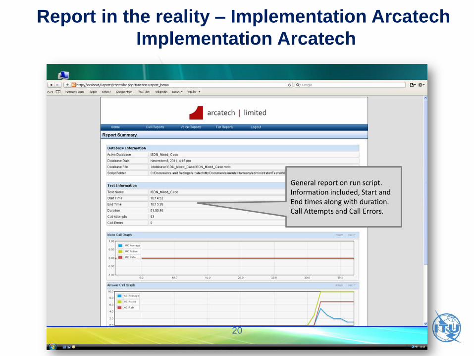
General report on run script. Information included, Start and End times along with duration. Call Attempts and Call Errors.
Report in the reality – Implementation Arcatech
Implementation Arcatech
20
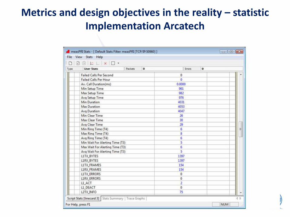
Metrics and design objectives in the reality – statistic Implementation Arcatech
21

Metrics and design objectives in the reality -charts for ramp traffic
Implementation Arcatech
22
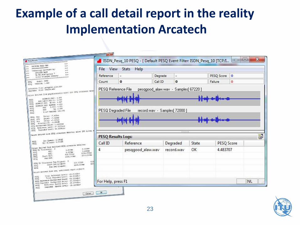
Example of a call detail report in the reality Implementation Arcatech
23
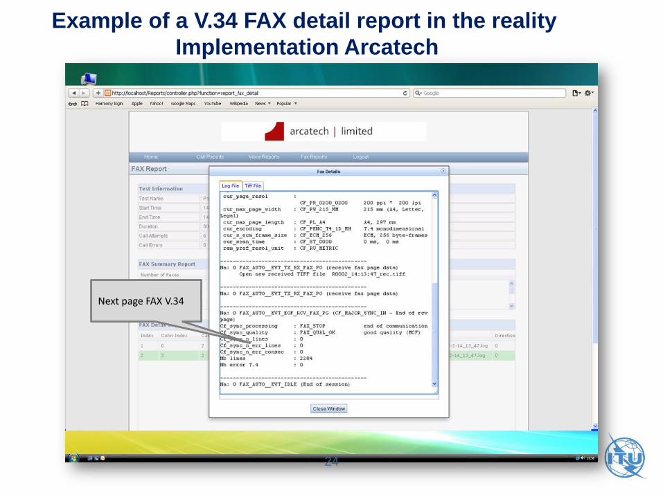
Next page FAX V.34
Example of a V.34 FAX detail report in the reality
Implementation Arcatech
24

25
Q.3933Reference benchmarking,
background traffic profiles and KPIs for VoIP and FoIP in fixed networks
The Recommendation Q.3933 describes Key Performance Indicators and benchmarking methods for the spectrum of potential applications. Access technologies considered are all technologies offered by the operator.
Scope
26
• The benchmarking platform can be distributed across a larger region or an entire country. In this case, several server systems should be also part of the set-up, including a system for evaluating media (e.g., video, audio, and voice) quality.
Scope of Functionality (1)
27
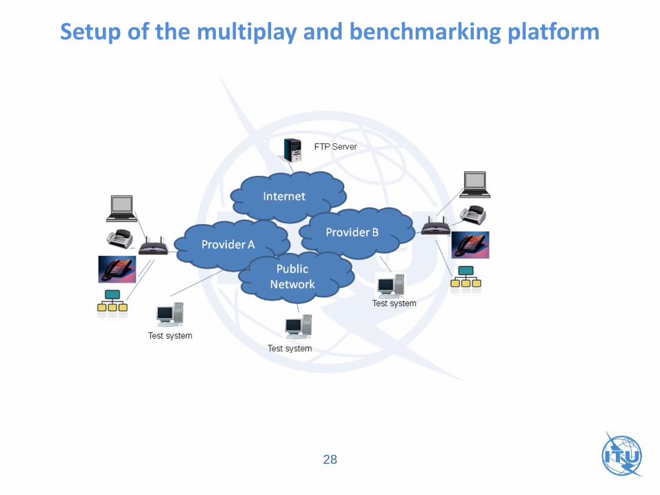
Setup of the multiplay and benchmarking platform
28

• The measurement systems at the user premises can be connected with IP, FXS or ISDN ports via a voice gateway (VGW), integrated access device (IAD), or directly to a CPE or Ethernet port (e.g., multimedia telephony service (MMTel) fixed access).
Scope of Functionality (2)
29
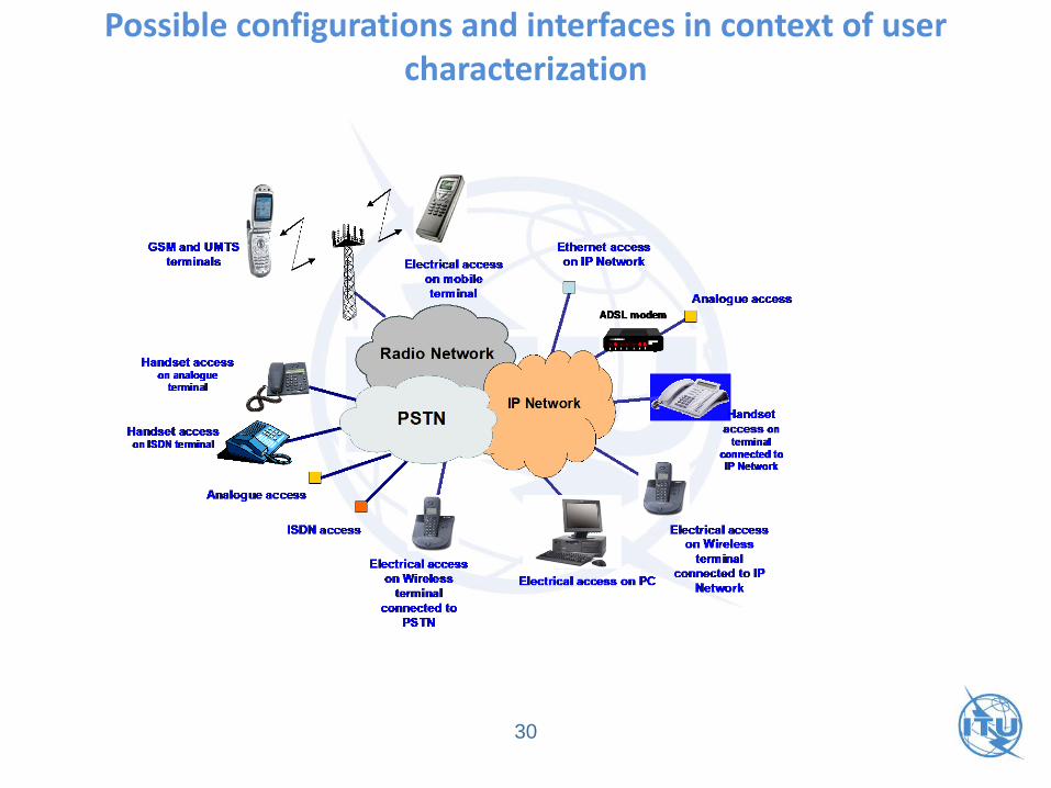
Possible configurations and interfaces in context of user characterization
30

Overview of Quality characteristics for voice quality measurements
31
1. call set up delay
2. call set-up time (Post Dialling Delay)
3. Call Setup Time Standard Deviation
4. Premature release probability (Call Failure Rate)
5. Call Drop Rate
6. Unsuccessful call ratio
7. Media establishment delay
8. Level of active speech signal
9. Noise level
10. Noise to signal ratio
11. Speech signal attenuation
12. Talker echo delay
13. Listening speech quality
14. Listening speech quality stability
15. End-to-End audio delay
16. End-to-End audio delay standard deviation
17. End –to-End audio delay variation
18. Frequency response
19. Fax transmission T.30 (Fax, bit rate ≤ 14,4 kbit/s and Fax, bit rate ≥ 14,4 kbit/s)

Example: Call set-up time (1)
32
Network
INVITE INVITE
180 Ringing 180 Ringing
200 OK
ACK
200 OK
ACK
Sending Speech Sample Recording Speech Sample
Recording Speech Sample Sending Speech Sample
BYE BYE
200 OK 200 OK
MU MUCPE „A“ Side CPE „B“Side

Example: Call set-up time (2)
33
Network
INVITE INVITE
180 Ringing 180 Ringing
200 OK
ACK
200 OK
ACK
Sending Speech Sample Recording Speech Sample
Recording Speech Sample Sending Speech Sample
BYE BYE
200 OK 200 OK
MU MUCPE „A“ Side CPE „B“Side