pseudo-dynamic testing for seismic performance assessment ... · assessment of buildings with...
TRANSCRIPT

Jan. 2014, Volume 8, No. 1 (Serial No. 74), pp. 73-88 Journal of Civil Engineering and Architecture, ISSN 1934-7359, USA
Pseudo-Dynamic Testing for Seismic Performance
Assessment of Buildings with Seismic Isolation System
Using Scrap Tire Rubber Pad Isolators
Huma Kanta Mishra1, Akira Igarashi2, Dang Ji2 and Hiroshi Matsushima2
1. Department of Urban Management, Kyoto University, Kyoto 615-8540, Japan
2. Department of Civil and Earth Resource Engineering, Kyoto University, Kyoto 615-8540, Japan
Abstract: Investigation of seismic performance of buildings with STRP (scrap tire rubber pad) seismic isolators by means of pseudo-dynamic tests and numerical simulation is presented. The isolated building is numerically modeled, while the base isolation layer is considered as the experimental substructure in the pseudo-dynamic tests. The test result verifies that the STRP isolator shows acceptable shear deformation performance predicted by the design methods, and demonstrated that seismic isolation using STRP works as a protective measure to provide enhanced seismic performance of the building indicated by the reduction of top floor absolute acceleration, drift and base shear as designated.
Key words: Pseudodynamic test, STRP isolator, numerical simulation, base isolation, seismic performance.
1. Introduction
Base isolation systems are being employed in
several earthquake-prone areas in the world to design
new buildings and to retrofit existing building
structures [1]. Application of this attractive technology
is limited to important and valuable structures. One of
the reasons for this situation is the size, weight and
incurred cost of the base isolation devices [2]. It should
be noted that commercially available base isolation
devices are far from the reach of a poor family in
developing countries. A reduction in the weight and
cost of seismic isolators would permit a significant
increase in their application to many ordinary
residential and commercial buildings [3].
Several studies have been conducted using either
steel laminated rubber bearing [4] or fiber-reinforced
elastomeric isolators [2, 3, 5] as low cost base isolation
systems for structures in highly seismic regions in the
world. These types of seismic isolators are still
Corresponding author: Huma Kanta Mishra, Ph.D.,
research field: structural dynamics lab. E-mail: [email protected].
economically unacceptable considering the purchasing
capacity of poor families in, for example, the South
Asian region. The solution of the above issues shall be
the development of base isolation systems which can
be effective in reducing the seismic demand of the
structures and are made of easily available materials at
an affordable cost.
As an economical and easily available option for the
base isolation system, the use of STRP (scrap tire
rubber pad) as seismic isolators has been proposed [6].
The STRP layers are fabricated by cutting out
rectangular-shaped rubber pads from the tread part of
scrap tires. Due to the strain constraining effect of steel
reinforcing cord layers embedded in the rubber pad,
STRP is expected to show high stiffness in axial
compression and supporting load capacity along with a
high level of flexibility and deformability in lateral
shear, which are suitable to the requirement for the
character of seismic isolators. The authors conducted
analytical and experimental study by means of loading
tests in static compression and shear in order to
evaluate the mechanical properties of layer-unbonded
DAVID PUBLISHING
D

Pseudo-Dynamic Testing for Seismic Performance Assessment of Buildings with Seismic Isolation System Using Scrap Tire Rubber Pad Isolators
74
and layer-bonded STRP samples for the purpose of
isolation device [7, 8].
Prior to their application in real building structures,
it is essential to assess how the base isolated building
with STRP isolators responds to dynamic loading.
When the response characteristics of a structural
system are not well understood or do not permit
numerical modeling, physical testing provides the only
accurate method to analyze the dynamic response of
the structure [9]. The two main methods currently used
to test the structures under the influence of dynamic
loading are the shake table test and the pseudo-dynamic
testing method [10]. Small-scale models of structures
have to be used in shake table tests because of the
limited size and capacity of the available shake tables
and therefore it is often difficult to investigate the
behavior of full scale structures. The other problem
associated with testing of the reduced scale model is
that the scale effect which may cause misleading of the
test results [11]. The pseudo-dynamic testing approach
can be used to avoid the limitations of the shake table
test along with the scale effects for evaluating the
performance of large scale structures under earthquake
loads. In addition, it is not necessarily required to test
the complete structure: An experimental test on a key
part of the structure can provide a better understanding
of the whole structural response [12]. In
pseudo-dynamic testing, a critical nonlinear structural
element that cannot be modeled satisfactorily is tested
physically while the remaining part of the structure that
can be modeled with confidence is modeled with a
numerical formulation. The former and the latter are
referred to as the experimental substructure and the
numerical substructure, respectively, in the
substructuring technique, which is a combination of
numerical simulation and experimental test on a
subpart of the structure which can be regarded as the
better understanding of the entire structural response
[12]. The loading of the experimental substructure is
conducted by using hydraulic actuators to apply the
target displacements to the experimental specimen.
The restoring force of the experimental substructure
recorded from the load cell of the actuators and that of
the numerical parts are integrated in parallel into
dynamic equation of equilibrium of the entire
structure [13].
In this work, seismic performance of STRP seismic
isolators is investigated by means of pseudo-dynamic
testing using a hypothetical three-story concrete frame
building model. The three-story building is represented
by a 3-DOF model with lumped mass at each floor
level and the lateral stiffness of each story represented
by an elastic shear spring. With an additional DOF
(degrees of freedom) assigned for the base isolation
floor, the structure is modeled as a 4-DOF system. The
base isolation system is considered as the experimental
part while the superstructure is considered to be the
numerical part. The STRP isolators were fabricated as
scale models of a hypothetical prototype isolator with a
scale factor of 1/3 due to the capacity of the testing
equipment available. In order to evaluate the seismic
performance of a building with STRP isolator
application, two levels of external seismic excitations
were used to evaluate the seismic performance of the
building. For this purpose, input accelerograms with
the amplitude of 1940 Imperial Valley Earthquake El
Centro record multiplied by 1.0 and 1.5 were used as
the input. The pseudo-dynamic test results were
compared with numerical simulation results to validate
the simulation results. These test results were further
compared with the numerical simulation results for the
fixed base building to evaluate the seismic response
performance of the purposed base isolation system.
2. STRP Isolator
The STRP specimens were prepared according to the
steps as outlined in Refs. [14-16]. As illustrated by Fig. 1,
STRP samples were fabricated by cutting out square
shape pads of dimensions 100 mm × 100 mm × 12 mm
from the tread part of the tires. The tire product used for
the preparation of STRP specimen samples in this
study is Bridgestone Tire, 385/65R22, 5. Each layer of

Pseudo-Dynamic Testing for Seismic Performance Assessment of Buildings with Seismic Isolation System Using Scrap Tire Rubber Pad Isolators
75
Fig. 1 STRP preparations using the tread part of the tire.
12
100
Steel reinforcing cords
Fig. 2 Cross section of a single layer STRP: sketch and photograph.
STRP isolator shown in Fig. 2 includes five layers of
steel reinforcing cords, comprising a number of strands
in twisted form and embedded in the rubber material in
interleaved orientations.
The raw STRP samples taken from a tire are sanded
using a belt sanding machine, so that smooth plain
surfaces are obtained on the STRP samples, and the
surfaces are cleaned to achieve proper good quality
adhesion between the surfaces. The chemical treatment
of the surfaces by applying the Chemlok 7701 primer
(Lord Corp.) with a brush improves compatibility with
adhesive and environmental resistance, thus making
the rubber surfaces more receptive to bonding. The
bonding between STRP samples is conducted
immediately after the solvent has flashed off to achieve
the best adhesion quality in creating layer-bonded
STRP samples.
The Fusor 320/322 (Lord Corp.) is used as the epoxy
adhesive containing resin and hardener compounds.
The adhesive is prepared as recommended by the
manufacturer for general purpose (temperature range
between -40 oC to 204 oC) application, and is applied
on both sides of STRP surfaces using a spatula with a
target thickness of 0.5 mm. Four STRP samples are
assembled into a layer-bonded STRP and pressure
(about 0.2 MPa) is applied. The layer-bonded STRP
samples are placed undisturbed for 24 h to achieve
fully cured. The isolator specimen prepared in this
manner is referred to as STRP-4 in this study. Fig. 3
shows the process of surface preparation, adhesive
application and cured samples. The dimensions of the
STRP-4 are shown in Table 1, and the material
properties of the STRP sample are presented in Table 2.
The rubber has shear modulus of 0.89 MPa and
hardness of 60 Durometer [17, 18].
The prototype isolator is assumed to be designed
with plan dimensions of 300 mm × 300 mm and
overall thickness of 150 mm. The thickness of the
isolators, corresponding to twelve layers of STRP, is
specified considering to achieve the target
displacement capacity at shear strain of 1.55 (based on
the thickness of rubber). The STRP-4 isolator
specimens with plan dimensions of 100 mm × 100 mm
can be interpreted as 1/3 scale models of the prototype
STRP isolators.
The type of similitude law to be applied to the
small-scale models depends on the aim and
methodology of the test. For a dynamic problem, if

Pseudo-Dynamic Testing for Seismic Performance Assessment of Buildings with Seismic Isolation System Using Scrap Tire Rubber Pad Isolators
76
(a) Sanding of a STRP layer (b) Single layer with adhesive on surface (c) Fully cured STRP-4 samples
Fig. 3 Preparation of STRP-4 specimen.
Table 1 Geometrical properties of STRP-4.
Dimensions of a single layer 100 mm × 100 mm × 12 mm
Thickness of steel reinforcing cords 0.4 mm
Adhesive 2 mm
Total thickness 50 mm
Nominal rubber thickness tr 40 mm
mass (M), length (L) and time (T) are selected as the
three basic dimensions, then all the variables involved
in the dynamics can be derived from them [19]. The
similitude law used for the pseudodynamic test in this
study is shown in Table 3.
3. Quasi-Static Tests
3.1 Loading System
The schematic view of the loading system used to
carry out the quasi-static loading tests, as well as the
substructure pseudo-dynamic test, is shown in Fig. 4.
This loading system consists of one, three and five
actuators in the x, y and z directions, respectively. In all
the directions, each actuator is pin-connected to the
reaction frame and to the rigid loading block. These
three actuators, namely, FX, FY and FZ actuators are
used to apply displacement and force in the respective
directions. In addition to these actuators, four actuators
are used to control the rotation with respect to x and y
axes and the remaining two actuators are used to
control the rotation with respect to z axis. The
specimen isolator is placed between the two steel plates
attached to the reaction frame and the loading block to
represent the superstructure and substructure,
respectively. No fastening system was used to connect
the specimen with the support surfaces. The capacity of
the loading system is shown in Table 4.
3.2 Test Procedure
Prior to the pseudodynamic tests, two quasi-static
cyclic loading tests were performed to investigate the
fundamental properties of the STRP isolator. The
constant vertical axial pressure of 10 MPa and 5 MPa
was applied for the two tests, which are referred to
QS10 and QS5 hereafter, respectively. The specimens
were loaded vertically with a constant load by the
load-controlled vertical actuator FZ, and a series of
Table 2 Material properties.
Parameters Values
Shear modulus G (tire rubber) 0.89 MPa
Young’s modulus E (steel cords) 200 GPa
Poisson’s ratio υ (steel cords) 0.3
Table 3 Similitude law for dynamic problem.
Physical quantity Dimension Scale factor Length L S Time T S Mass M s3 Velocity LT-1 1 Acceleration LT-2 s-1 Displacement L S Force MLT-2 s2 Stiffness MT-2 S

Pseudo-Dynamic Testing for Seismic Performance Assessment of Buildings with Seismic Isolation System Using Scrap Tire Rubber Pad Isolators
77
Fig. 4 Schematic view of loading system.
Table 4 Capacity of testing facility.
Actuator Max. displacement (mm) Max. load (kN) Direction Notation
No. 1 ±100 ±500 Vertical FZ
No. 2 ±100 ±100 Horizontal FX
No. 3 ±100 ±100 Horizontal FY
horizontal cyclic displacements were applied with the
horizontal actuator FX. The horizontal actuator FY was
utilized to constrain the out-of-plane movement of the
loading block.
For the QS10, the 1/3 scale model isolator was
tested in cyclic shear with three fully reversed cycles
at three maximum shear displacement amplitudes of
20, 40 and 60 mm, corresponding to shear strain of
50%, 100% and 150%, respectively. Similar
procedure was followed for the QS5, except that the
test was conducted with reduced displacement
amplitudes of 15, 30, 45 and 60 mm which correspond
to shear strain of 37.5%, 75%, 112.5% and 150%,
respectively. The test results of QS10 and QS5 were
used to determine the mechanical properties of the
specimen including stiffness and equivalent
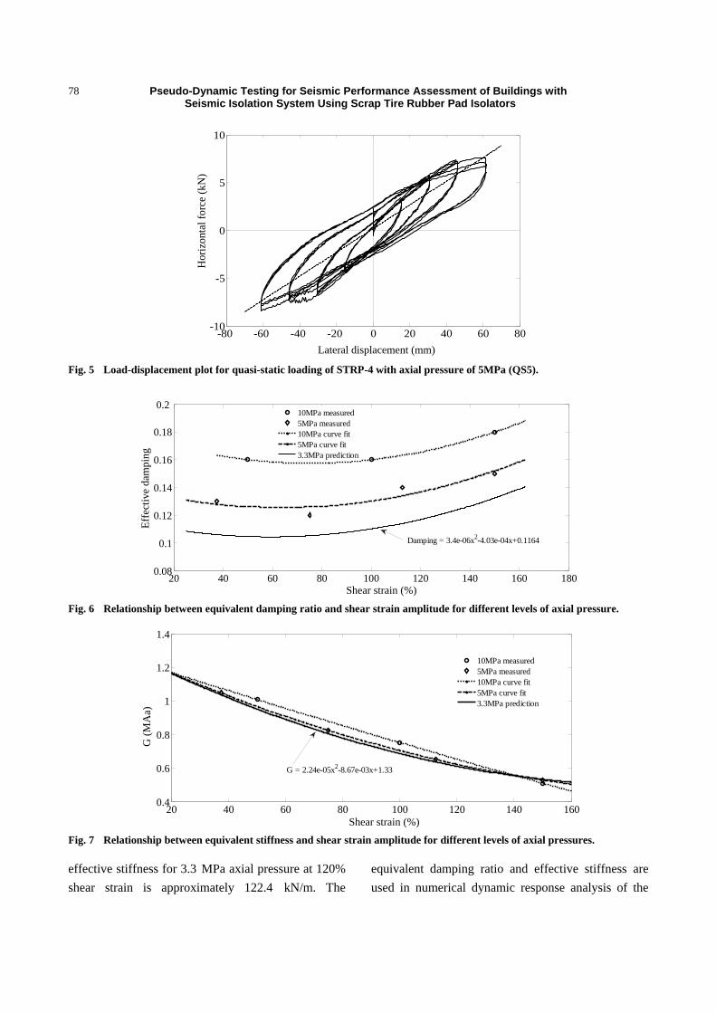
damping ratio. As a representative test result, lateral
load-displacement obtained by test QS5 is shown
in Fig. 5. Detailed result of quasi-static loading
test of STRP-4 specimen is described in Ref.
[8].
3.3 Parameter Identification
The effective stiffness and equivalent damping ratio
of the tested STRP isolators were determined by the
quasi-static loading test results. The target fundamental
period of the isolation system was determined
considering the stability and acceptable displacement
capacity. The required parameters were determined to
achieve the target period of 1.8 s. First of all, the test
results of QS5 and QS10 were plotted, and then the
relationship between effective damping and shear
strain for 3.3 MPa axial pressure was predicted. The
relationship between the equivalent damping ratio and
shear strain for different levels of axial pressures is
shown in Fig. 6. The predicted equivalent damping
ratio under the 3.3 MPa axial pressure at 120% shear
strain is approximately 0.11. A similar technique was
adopted to predict the effective stiffness of the tested
isolators. The relationship between effective stiffness
and shear strain for different level of axial pressures is
shown in Fig. 7. This figure shows that the variation of
effective stiffness is not significant. The predicted
x
y
z
Pseudo-Dynamic Testing for Seismic Performance Assessment of Buildings with Seismic Isolation System Using Scrap Tire Rubber Pad Isolators
78
Fig. 5 Load-displacement plot for quasi-static loading of STRP-4 with axial pressure of 5MPa (QS5).
Fig. 6 Relationship between equivalent damping ratio and shear strain amplitude for different levels of axial pressure.
Fig. 7 Relationship between equivalent stiffness and shear strain amplitude for different levels of axial pressures.
effective stiffness for 3.3 MPa axial pressure at 120%
shear strain is approximately 122.4 kN/m. The
equivalent damping ratio and effective stiffness are
used in numerical dynamic response analysis of the
-80 -60 -40 -20 0 20 40 60 80-10
-5
0
5
10
Lateral displacement [mm]
Hor
izon
tal f
orce
[kN
]
20 40 60 80 100 120 140 160 1800.08
0.1
0.12
0.14
0.16
0.18
0.2
Shear strain [%]
Eff
ectiv
e da
mpi
ng
10MPa measured5MPa measured10MPa curve fit5MPa curve fit3.3MPa prediction
Damping = 3.4e-06x2-4.03e-04x+0.1164
20 40 60 80 100 120 140 1600.4
0.6
0.8
1
1.2
1.4
Shear strain [%]
G [
MP
a]
10MPa measured5MPa measured10MPa curve fit5MPa curve fit3.3MPa prediction
G = 2.24e-05x2-8.67e-03x+1.33
Lateral displacement (mm)
Hor
izon
tal f
orce
(kN
)
Shear strain (%)
Eff
ecti
ve d
ampi
ng
Shear strain (%)
G (
MA
a)

Pseudo-Dynamic Testing for Seismic Performance Assessment of Buildings with Seismic Isolation System Using Scrap Tire Rubber Pad Isolators
79
structural model as described later.
4. Pseudo-Dynamic Tests
4.1 Building Model
A series of pseudo-dynamic tests were conducted on
the hypothetical numerical model of a three-story
reinforced concrete moment-resisting frame structure
building with brick masonry infill walls isolated by
STRP isolators to simulate the structural seismic
response involving STRP isolators and to verify the
efficiency. The building with dimensions of 7.85 m by
11.25 m in plan and 9.0 m in height, shown in Fig. 8a,
was designed in based on the provisions of NBC
(Nepal Building Code) [20] and UBC 1997 (Uniform
Building Code 1997) [15]. All the columns are of a
square cross section of 300 mm by 300 mm and all the
beams are of 230 mm in width and 350 mm in depth. A
floor slab is added at the ground level to provide
physical separation between the substructure and
superstructure. The building was designed on a stiff
soil site with the seismic zoning factor of 1.0 as per
NBC. For the analysis of the fixed-base building, the
infill walls were not included in the lateral force
resisting system. The weight of the structure including
25% for seismic design is approximately 4,396 kN.
The fundamental period of the fixed-base structure
was calculated to be equal to 0.31 s by using the Eq. (1)
given in NBC. The fixed-base period of the building is
approximately 0.51 s.
43
06.0 HTt (1)
where, H is the height of the building in meter.
There are a total of 15 STRP isolators that are
installed under each of the columns. The STRP
isolators were assumed as designed to be applied to the
building in accordance with the building column loads
with the loading combination 1.2 DL + 1.0 LL + |E| as
in UBC, 1997 [15]. The average axial compressive
pressure on an isolator is approximately 3.3 MPa,
although the axial compressive pressure varies
depending on the location of the isolator. The size and
thickness of the isolators were computed so that 1.8 s
base isolation period is achieved. The equations of
motion were formulated for the entire structure with
base isolation, represented as a 4-DOF system, as
shown in Fig. 8b. The mass and stiffness properties of
the building are shown Table 5. The stiffness properties
were computed excluding the brick masonry infill
walls.
Simulationpart
Tested part
m3
m2
m1
mb
k1,c1
k2,c2
k3,c3
Unit: m3.34.253.7
Base
First
Second
Roof
a) b)
(a) (b)
Fig. 8 Model of building with base isolation: (a) basic dimensions; (b) division into simulation and experimental parts.
Pseudo-Dynamic Testing for Seismic Performance Assessment of Buildings with Seismic Isolation System Using Scrap Tire Rubber Pad Isolators
80
Table 5 Mass and stiffness properties of building model.
Level Mass (t) Horizontal stiffness (kN/mm)
Base 85.0 5.5
First 127.6 87.1
Second 127.6 87.1
Roof 108.2 87.1
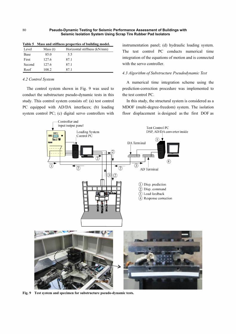
4.2 Control System
The control system shown in Fig. 9 was used to
conduct the substructure pseudo-dynamic tests in this
study. This control system consists of: (a) test control
PC equipped with AD/DA interfaces; (b) loading
system control PC; (c) digital servo controllers with
instrumentation panel; (d) hydraulic loading system.
The test control PC conducts numerical time
integration of the equations of motion and is connected
with the servo controller.
4.3 Algorithm of Substructure Pseudodynamic Test
A numerical time integration scheme using the
prediction-correction procedure was implemented to
the test control PC.
In this study, the structural system is considered as a
MDOF (multi-degree-freedom) system. The isolation
floor displacement is designed as the first DOF as
Fig. 9 Test system and specimen for substructure pseudo-dynamic tests.

Pseudo-Dynamic Testing for Seismic Performance Assessment of Buildings with Seismic Isolation System Using Scrap Tire Rubber Pad Isolators
81
represented by the first component of the displacement
vector {x}1. After imposing the displacement in the
next step { 1~
nx }1 to the STRP isolator specimen, the
measured restoring force fn+1 is used to evaluate the
correction force increment vector {fc}, which is the
difference between the restoring force based on the
initial elastic stiffness and the actual load. The
correction force increment vector for the isolation floor
can be expressed by Eq. (2).
111111~
nnnnc xxkfff (2)
where, is the restoring force of the experimental
substructure in the previous step, is the elastic
stiffness of the shear spring 1 in the MDOF system.
Accordingly, the procedure used to calculate the
response at time (n+1)t can be outlined as below:
Step 1: Calculate the response displacement vector at the next step { 1
~nx } for the entire structural model
using Eq. (3):
2121
ˆˆ5.0~ tfMxtxtxx nnnn
(3)
where,
KtCtMM 25.0ˆ (4)
nn xKtxKtCttzMf 5.0)(1ˆ (5)
Step 2: Apply the predicted displacement of the
experimental substructure { 1~
nx } as the target
displacement command to the loading system.
Step 3: Measure the feedback restoring force fn+1
from the experimental substructure.
Step 4: Calculate the corrected displacement using
Eq. (6):
21
11ˆ~ tfMxx cnn
(6)
If the correction part β[ M̂ ]-1{fc}-1t2 is sufficiently
small, then compute the velocity and acceleration by
Eqs. (7) and (8), respectively, and proceed to the next
step, otherwise, substitute {xn+1} as predicted
displacement { 1~
nx }1 and go back to Step 2.
txxxx nnnn 11 5.0 (7)
cnn ffMxx
ˆˆ 1
1 (8)
The convergence tolerance is selected depending on
the finite resolution of the loading control system and
measuring devices. There are merits and demerits of
using a small convergence tolerance limit, and of using
a large one. In this test, the displacement tolerances
were set as 0.1 mm.
4.4 Test Program and Result
For the purpose of the pseudo-dynamic test, NS
component of the El Centro record of 1940 Imperial
Valley Earthquake (Fig. 10) and the accelerogram
scaled with the factor 1.5 were used as the seismic
input to the building model shown in Fig. 8.
In this study, the pseudodynamic tests of the
specimen isolator were conducted under a constant
vertical axial pressure of 3.3 MPa. The seismic
responses of the prototype model obtained by the
pseudodynamic tests were compared with the
simulation results with respect to the top floor absolute
acceleration, top floor drift, isolator’s displacement and
base shear transmitted to the superstructure. Fig. 11
shows the force-displacement relationship of the
isolator obtained from the pseudo-dynamic tests using
100% and 150% El Centro records for shear strain
levels of 70% and 100%. The corresponding deformed
state of the STRP isolator is shown in Fig. 12. These
shear strains are well within the deformation capacity
of the STRP-4 specimen of approximately 150%
obtained by the quasi-static loading test.
5. Numerical Dynamic Analysis
The numerical dynamic analysis of the building
isolated with the STRP isolators was carried out using
the MDOF model shown in Fig. 8b, in which the
hysteretic behavior of the STRP seismic isolator is
modeled as a combination of a linear spring and
viscous damping determined from the force
displacement relationship obtained from the previous
quasi-static tests on similar type of isolators.
The linearized procedure uses effective stiffness and
effective damping to characterize the nonlinear
properties of isolators. Eurocode [21] permits
modeling of the isolation system with an equivalent

Pseudo-Dynamic Testing for Seismic Performance Assessment of Buildings with Seismic Isolation System Using Scrap Tire Rubber Pad Isolators
82
Fig. 10 Input accelerogram (El Centro 1940, NS component, PGA = 0.313 g).
(a) 100% El Centro NS input case (b) 150% El Centro NS input case
Fig. 11 Force displacement relationship of STRP-4.
(a) 70% shear strain (b) 100% shear stain
Fig. 12 Deformed state of STRP-4 observed during pseudodynamic test.
linear elastic-viscous behavior, if it consists of devices
such as laminated elastomeric bearings. When an
equivalent linear model is used, the effective stiffness
of each isolator unit should be used, and energy
dissipation of the isolation system should be expressed
in terms of an equivalent viscous damping as the
effective damping. Similarly, FEMA [22] permits
linear procedures with certain limitations. Although the
static response of a structure supported on a system of
this type shows a bilinear hysteretic restoring force
behavior [23], equivalent linear elastic models are
often used in order to simplify the design and analysis
of seismically isolated buildings, at least at the
preliminary design and analysis phase [24]. According
to Uniform Building Code [15], the nonlinear-force
deformation characteristic of the isolator can be
0 5 10 15 20 25 30 35 40-0.4
-0.2
0
0.2
0.4
Time [sec]
Acc
eler
atio
n [g
]
-80 -40 0 40 80-60
-40
-20
0
20
40
60
Displacement [mm]
For
ce [
kN]
-120 -80 -40 0 40 80 120-80
-40
0
40
80
Displacement [mm]
For
ce [
kN]
Time (s)
Acc
eler
atio
n (g
)
For
ce (
kN)
Displacement (mm) Displacement (mm)
For
ce (
kN)

Pseudo-Dynamic Testing for Seismic Performance Assessment of Buildings with Seismic Isolation System Using Scrap Tire Rubber Pad Isolators
83
replaced by an equivalent linear model through
effective elastic stiffness and viscous damping. In the
current design practices for seismically isolated
structures, an equivalent linear elastic structure with an
effective period and an equivalent viscous damping
ratio accounting for energy dissipation due to inelastic
deformation of isolator is usually used for preliminary
design [25]. Mavronicola et al. [24] concluded that the
equivalent linear analysis may be used under certain
limitations for the preliminary design and analysis of a
seismically isolated building. Bilinear modeling would
produce better result if the yield displacement and
corresponding force could be determined with a good
accuracy. However, unlike the other virgin rubbers,
determination of yield displacement of STRP is
difficult.
The governing equation of motion for the base
isolated structure can be written as Ref. [26] sss xKxCxM
gbs xxrM (9)
where, Ms, Ks and Cs are the mass, stiffness and
damping matrices of the superstructure. x , x and
x are the displacement, velocity and acceleration vectors of the superstructure, respectively, gx and bx
are the excitation acceleration and acceleration of bass
floor, respectively, and r represents the influence
coefficient vector.
The corresponding equation of motion for the base
mass under earthquake ground motion is expressed by:
gbbbb xmxkxcFxm 1111 (10)
where, mb is the base floor mass, Fb is the restoring
force of isolation system, c1 and k1 are the first story
damping and stiffness, respectively. In Eq. (10), mass
and stiffness matrices are known but the damping
matrix of the superstructure is not known explicitly.
The STRP bearings were modeled by using equivalent
linear elastic viscous damping model. The linear
force developed in the isolation system can be
expressed as:
beffbeffb xcxkF (11)
where, keff and ceff are the effective stiffness and
effective damping value of the isolation system.
The damping matrix Cs of the superstructure has to
generate either by using the modal damping or by using
Rayleigh damping [27].
In this model, first and fourth modes were used to
define the superstructure’s damping matrix with 5%
critical damping. The overall damping matrix C is
obtained by assembling the damping matrices of the
superstructure and the isolation system. As the time
integration scheme, Newmark’s method with = 1/6
and = 1/2 with the time step interval of t = 0.001 s
was used.
6. Comparison between Pseudo-dynamic Test and Numerical Analysis Results
The results of the pseudo-dynamic tests and numerical
analysis are described. Fig. 13 shows the comparison
between the numerical analysis and pseudo-dynamic
tests results in terms of the force-displacement behavior.
(a) 100% El Centro input case (b) 150% El Centro input case
Fig. 13 Force-displacement relationship of STRP isolator: comparison between pseudodynamic test and numerical analysis results.
-80 -40 0 40 80-60
-40
-20
0
20
40
60
Displacement [mm]
For
ce [
kN]
AnalysisPseudodynamic test
-120 -80 -40 0 40 80 120-80
-40
0
40
80
Displacement [mm]
For
ce [
kN]
AnalysisPseudodynamic test
Displacement (mm) Displacement (mm)
For
ce (
kN)
For
ce (
kN)
Pseudo-Dynamic Testing for Seismic Performance Assessment of Buildings with Seismic Isolation System Using Scrap Tire Rubber Pad Isolators
84
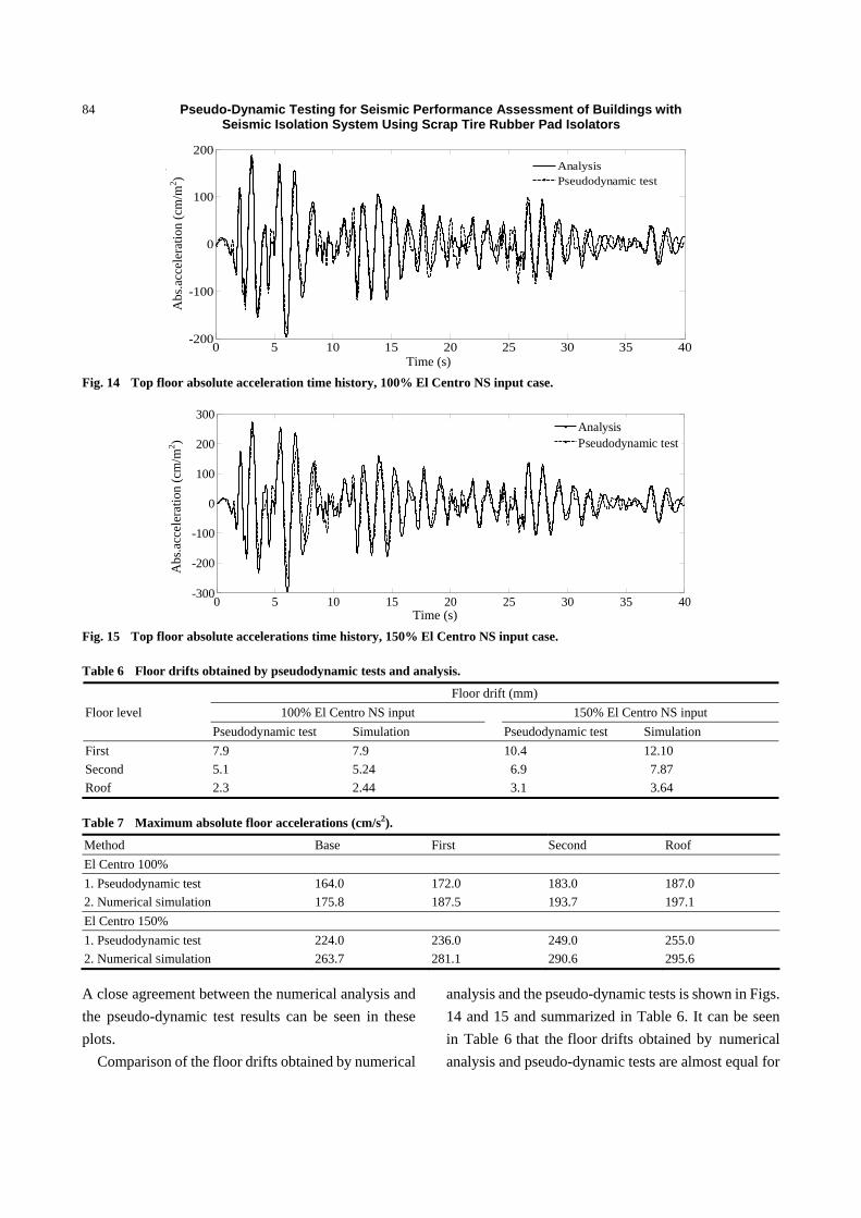
Fig. 14 Top floor absolute acceleration time history, 100% El Centro NS input case.
Fig. 15 Top floor absolute accelerations time history, 150% El Centro NS input case.
Table 6 Floor drifts obtained by pseudodynamic tests and analysis.
Floor level
Floor drift (mm)
100% El Centro NS input 150% El Centro NS input
Pseudodynamic test Simulation Pseudodynamic test Simulation
First 7.9 7.9 10.4 12.10
Second 5.1 5.24 6.9 7.87
Roof 2.3 2.44 3.1 3.64
Table 7 Maximum absolute floor accelerations (cm/s2).
Method Base First Second Roof
El Centro 100%
1. Pseudodynamic test 164.0 172.0 183.0 187.0
2. Numerical Simulation 175.8 187.5 193.7 197.1
El Centro 150%
1. Pseudodynamic test 224.0 236.0 249.0 255.0
2. Numerical Simulation 263.7 281.1 290.6 295.6
A close agreement between the numerical analysis and
the pseudo-dynamic test results can be seen in these
plots.
Comparison of the floor drifts obtained by numerical
analysis and the pseudo-dynamic tests is shown in Figs.
14 and 15 and summarized in Table 6. It can be seen
in Table 6 that the floor drifts obtained by numerical
analysis and pseudo-dynamic tests are almost equal for
0 5 10 15 20 25 30 35 40-200
-100
0
100
200
Time [sec]
Abs
.acc
eler
atio
n [c
m/s
ec2 ]
AnalysisPseudodynamic test
0 5 10 15 20 25 30 35 40-300
-200
-100
0
100
200
300
Time [sec]
Abs
. acc
eler
atio
n [c
m/s
ec2 ]
AnalysisPseudodynamic test
Time (s)
Abs
.acc
eler
atio
n (c
m/m
2 ) A
bs.a
ccel
erat
ion
(cm
/m2 )
Time (s)

Pseudo-Dynamic Testing for Seismic Performance Assessment of Buildings with Seismic Isolation System Using Scrap Tire Rubber Pad Isolators
85
Fig. 16 Comparison of floor displacements profile for different input amplitude level.
100% El Centro input case, while the difference is
noticeable for the case of an increased level of
excitation with the scale factor of 1.5. Situation is
similar for the top floor absolute acceleration, as shown
in Table 7. Although the effective stiffness of the STRP
isolator decreases with increase in lateral displacement,
a constant effective stiffness value is determined for
120% shear strain is used in the dynamic analysis of the
STRP isolator, resulting in higher displacement
demand. Since the damping ratio is also dependent on
shear strain as shown in Fig. 6, use of a constant
effective damping ratio may lead to discrepancy
between the test and analysis results. Fig. 16 shows the
floor displacement profile obtained by the
pseudodynamic test. These results indicate that the
equivalent linear elastic-viscous damping model
overestimate the displacement demand which can be
considered appropriate for preliminary analysis and
design of STRP isolators.
A greater difference between the pseudodynamic
test results and simulation results is observed for the
case of the increased input acceleration amplitude. The
maximum difference is found for roof level absolute
acceleration which is about 15% higher than the
pseudodynamic test result. From Tables 6 and 7, it can
be concluded that the floor acceleration obtained by
numerical simulation is slightly higher than the
pseudodynamic test result in all cases. There may be
substantial increase in the top floor acceleration as the
fundamental period of the superstructure increases. In
this analysis, superstructure is considered as
rigid.
7. Comparison between Fixed Base and Base Isolated Case
The pseudodynamic tests results are further
compared with the results of analysis of the fixed base
case for the identical building. The seismic
performance of the isolated building is evaluated in
terms of absolute acceleration, drift and base shear. The
comparative response time histories are presented in
Figs. 17-19. The comparison of floor drifts for fixed
base and base isolated buildings for the two levels of
100% and 150% El Centro record excitation is also
shown in Fig. 20. An important index for the
performance evaluation of the base isolation system is
the peak inter-story drift. In this case, the inter-story
drift at the top is reduced with approximately 81%,
which is within the limit of 0.02/RI as designed [15].
The base shear force transmitted to the superstructure
Fig. 17 Top floor drift: comparison between numerical analysis of fixed base case and pseudodynamic test of base isolation case.
0 2 4 6 8 10 12 140
Base
First
Second
Roof
Floor displacement [cm]
Flo
or l
evel
100% El Centro input150% El Centro input
0 5 10 15 20 25 30 35 40-20
-10
0
10
20
Time [sec]
Roo
f dr
ift [
mm
]
Fixed baseBase isolated
Floor displacement (cm)
Flo
or le
vel
Time (s)
Roo
f dr
ift (
mm
)

Pseudo-Dynamic Testing for Seismic Performance Assessment of Buildings with Seismic Isolation System Using Scrap Tire Rubber Pad Isolators
86
Fig. 18 Top floor absolute acceleration: comparison between numerical analysis of fixed base case and pseudodynamic test of base isolation case.
Fig. 19 Base shear: comparison between numerical analysis of fixed base case and pseudodynamic test of base isolation case.
for fixed base and base isolation cases are 3,740 kN
and 1,124 kN, respectively. These results indicate that
the reduction of base shear due to base isolation is as
much as 70% of that for the fixed base case. It can be
concluded that, on an average, numerical analysis of
the fixed base case predicts 15% higher top floor drifts
and 13% higher top floor absolute accelerations
compared with the building with the base isolation.
Considering these variations, one can conclude that the
reduction of top floor drifts, top floor absolute
accelerations and base shear are 66%, 67% and 70%,
respectively.
8. Conclusions
As a part of the development of a low-cost seismic
isolation system, seismic performance of a building
with seismic isolators using scrap tire rubber pad is
verified by means of the pseudo-dynamic test in this
study. Although accurate numerical modeling of the
dynamic behavior of tire rubber pads by analytical
methods is difficult, dynamic response of the base
Fig. 20 Floor drift profile in fixed base and base isolation cases under 100% and 150% El Centro NS record input.
0 5 10 15 20 25 30 35 40-1500
-1000
-500
0
500
1000
1500
Time [sec]
Abs
. acc
eler
atio
n [c
m/s
ec2 ]
Fixed baseBase isolated
0 5 10 15 20 25 30 35 40-4000
-2000
0
2000
4000
Time [sec]
Bas
e sh
ear
[kN
]
Fixed baseBase isolated
0 10 20 30 40 501
1.5
2
2.5
3
3.5
4
Floor drift [mm]
Flo
or le
vel
BI 100%BI 150%FB 100%FB 150%
4,000
2,000
0
-2,000
-4,000
Time (s)
Bas
e sh
ear
(kN
)
Floor drift (mm)
Flo
or le
vel
Time (s)
Abs
.acc
eler
atio
n (c
m/m
2 )
1,500
1,000
500
0
-500
-1,000
-1,500

Pseudo-Dynamic Testing for Seismic Performance Assessment of Buildings with Seismic Isolation System Using Scrap Tire Rubber Pad Isolators
87
isolation system as well as seismic performance of a
three story base isolated building using STRP isolators
can be evaluated while avoiding the problems
associated with shaking table tests.
The isolators used in this study were produced by
using scrap tire rubber pads. Due to the capacity of
testing equipment available, 1/3 scale isolator models
were used as the specimens in the pseudo-dynamic test.
The mechanical properties of the tested isolators were
determined by conducting quasi-static cyclic loading
tests. Seismic performance of the base isolated building
was evaluated for two levels of seismic excitation: The
El Centro record scaled with 100% and 150%
amplitudes corresponding to the PGA values of 0.313 g
and 0.47 g, respectively.
The maximum responses obtained from numerical
simulation were found to be in reasonable agreement
with pseudodynamic tests results. The seismic
performance of the base isolated building was
evaluated in terms of absolute acceleration, drift, base
shear and isolator’s displacement compared with
numerical simulation results for the fixed base building.
In this case, the reduction of the top floor inter-story
drift and absolute acceleration are approximately 66%
and 67%, respectively, and base shear force transmitted
to the superstructure is reduced to 70% of that for the
fixed base building, showing that the top floor drift is
within the limit of 0.02/RI. These results indicate that
the base isolation system using STRP isolators is an
attractive alternative to commercially available
isolation systems.
References
[1] L. di Sarno, E. Chioccarelli, E. Cosenza, Seismic response of an irregular base isolated building, Bulletin of Earthquake Engineering 9 (5) (2011) 1673-1702.
[2] J.M. Kelly, Seismic isolation system for developing countries, Earthquake Spectra 18 (3) (2002) 385-406.
[3] H. Toopchi-Nezhad, M.J. Tait, R.G. Drysdale, Testing and modeling of square carbon fiber-reinforced elastomeric seismic isolators, Structural Control and Health Monitoring 15 (6) (2008) 876-900.
[4] J.M. Kelly, D. Konstantinidis, Low-cost seismic isolators for housing in highly-seismic developing countries, in:
10th World Conference on Seismic Isolation, Energy Dissipation and Active Vibrations Control of Structures, Istanbul, Turkey, May 2007, pp. 28-31.
[5] A. Mordini, A. Strauss, An innovative earthquake isolation system using fiber reinforced rubber bearings, Engineering Structures 30 (10) (2008) 2739-2751.
[6] A. Turer, B. Özden, Seismic base isolation using low-cost scrap tire pads (STP), Materials and Structures 41 (5) (2008) 891-908.
[7] H.K. Mishra, A. Igarashi, H. Matsushima, Finite element
analysis and experimental verification of the scrap tire
rubber pad isolator, Bulletin of Earthquake Engineering 11
(2013) 687-707.
[8] H.K. Mishra, I. Akira, Lateral deformation capacity and stability of layer-bonded scrap tire rubber pad isolators under shear loading, Bulletin of Earthquake Engineering. (in print)
[9] J.E. Carrion, B.F. Spencer, B.M. Philips, Real-time hybrid
testing of a semi-actively controlled structure with an MR
damper, in: American Control Conference, USA, 2009.
[10] A.P. Darby, A. Blakeborough, M.S. Williams, Real-time
substructure tests using hydraulic actuator, Journal of
Engineering Mechanics 125 (10) (1999) 1133-1139.
[11] H. Krawinkler, Scale effects in static and dynamic model
testing of structures, in: Proceedings of Ninth World
Conference on Earthquake Engineering, Japan, 1988.
[12] A. Souid, A. Delaplace, F. Ragueneau, R. Desmorat,
Pseudodynamic testing and nonlinear substructuring of
damaging structures under earthquake loading,
Engineering Structures 31 (5) (2009) 1102-1110.
[13] S.A. Mahin, P.B. Shing, Pseudodynamic method for
seismic testing, Journal of Engineering Structures 111 (7)
(1985) 1482-1503.
[14] S.K. Jain, S.K. Thakar, Quasi-static testing of laminated
rubber bearings, Journal of the Institution of Engineers
(India), Civil Engineering Division 84 (2003) 110-115.
[15] Earthquake Regulations for Seismic Isolated Structure,
Structural Design Requirements, Vol. 2, Uniform Building
Code (UBC 1997), Whittier, CA, 1997.
[16] J.M. Kelly, Earthquake-Resistant Design with Rubber,
2nd ed., Springer-Verlag, London, 1997.
[17] Y.J. Arditzoglou, J.A. Yura, A.H. Haines, Test Methods
for Elastomeric Bearing on Bridges, Texas Department of
Transportation, Research report 1304-2, 1995.
[18] H. Holcher, M. Tewes, N. Botkin, M. Lohndorf, K.H.
Hoffmann, E. Quandt, Modeling of pneumatic tires by a
finite element model for the development of a tire friction
remote sensor, Technical Paper, Center of Advanced
European Studies and Research (Caesar), 2004, p. 40.
[19] N.S. Kim, J.H. Lee, S.P. Chang, Equivalent multi-phase similitude law for pseudodynamic test on small scale reinforced concrete models, Engineering Structures 31 (4)

Pseudo-Dynamic Testing for Seismic Performance Assessment of Buildings with Seismic Isolation System Using Scrap Tire Rubber Pad Isolators
88
(2009) 834-846. [20] Nepal National Building Code, NBC 105, 1994. [21] Design of Structures for Earthquake Resistance, Eurocode
8, UK, 2004. [22] Federal Emergency Management Agency FEMA 273, the
National Earthquake Hazards Reduction Program (NEHRP) Guidelines for Seismic Rehabilitation of Buildings,1997.
[23] R.I. Skinner, J.A. Beck, G.N. Bycroft, A practical system for isolating structures from earthquake attack, Earthquake Engineering and Structural Dynamics 3 (3) (1975) 297-309.
[24] E. Mavronicola, P. Komodromos, Assessing the suitability of equivalent linear elastic analysis of seismically isolated
multi-story buildings, Computers and Structures 89 (21-22) (2011) 1920-1931.
[25] X.Z. John, J. Zhang, Inelastic demand spectra for bilinear seismic isolation systems based on nonlinear time history analysis and the response of lead-rubber bearing isolation systems subjected to near-source ground motions, Bulletin of the New Zealand Society for Earthquake Engineering 40 (1) (2007) 7-17.
[26] V.A. Matsagar, R.S. Jangid, Influence of isolator characteristics on the response of base-isolated structures, Engineering Structures 26 (2003) 1735-1749.
[27] K.L. Ryan, J. Polanco, Problems with Rayleigh damping in base-isolated buildings, Journal of Structural Engineering 134 (11) (2008) 1780-1784.