ps-8r ii - power conditioner / sequencer · ps-8r ii - power conditioner / sequencer introduction...
TRANSCRIPT
PS-8R I I - POWER CONDIT IONER / SEqu ENCER
PS-8R I I - POWER CONDIT IONER / SEqu ENCER
IntroductIon
The Series II power conditioners feature Furman’s revolutionary Series Multi-Stage Protection Plus (SMP+) circuit, as well as our exclusive Linear Filtering Technology (LiFT). Together, these technologies comprise what is, without question, the world's most advanced and comprehensive transient voltage surge suppressor / conditioner.
SMP+ (Series Multi-Stage Protection Plus)Furman’s SMP+ surge suppression virtually eliminates service calls. Traditional surge sup-pression circuits “sacrifice” themselves when exposed to multiple transient voltage spikes, requiring the dismantling of your system, and repair of your surge suppressor. With Furman’s SMP+, however, damaging transient voltages are safely absorbed, clamped, and dissipated.
unique to Furman’s SMP+ is its unparalleled clamping voltage. While other designs offer clamping voltages that are well above 330 Vpk, SMP+ clamps at 188 Vpk, (133 VAC RMS). This unprecedented level of protection is only available with Furman’s SMP+ technology. Additionally, Furman’s trusted over-voltage cir-cuitry protects against all too frequent acciden-tal connections to 208 or 240 VAC, by shutting off the incoming power until the over voltage condition is corrected.[For E versions: Furman’s SMP+ clamps at 376 VpK, (266 VAC RMS.)]
features
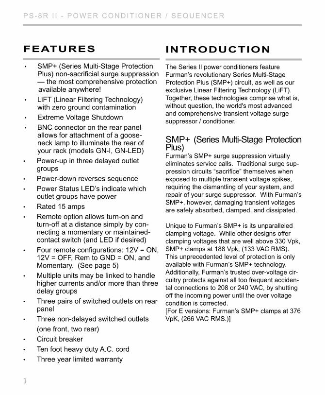
• SMP+ (Series Multi-Stage Protection Plus) non-sacrificial surge suppression — the most comprehensive protection available anywhere!
• LiFT (Linear Filtering Technology) with zero ground contamination
• Extreme Voltage Shutdown
• BNC connector on the rear panel allows for attachment of a goose- neck lamp to illuminate the rear of your rack (models GN-I, GN-LED)
• Power-up in three delayed outlet groups
• Power-down reverses sequence
• Power Status LED’s indicate which outlet groups have power
• Rated 15 amps
• Remote option allows turn-on and turn-off at a distance simply by con- necting a momentary or maintained- contact switch (and LED if desired)
• Four remote configurations: 12V = ON, 12V = OFF, Rem to GND = ON, and Momentary. (See page 5)
• Multiple units may be linked to handle higher currents and/or more than three delay groups
• Three pairs of switched outlets on rear panel
• Three non-delayed switched outlets
(one front, two rear)
• Circuit breaker
• Ten foot heavy duty A.C. cord
• Three year limited warranty
1
PS-8R I I - POWER CONDIT IONER / SEqu ENCER
lIft (linear filtering technology)
Traditional AC filter - conditioners have been designed for unrealistic laboratory conditions. Prior technologies, whether multiple pole filter or conventional series mode, could actually harm audio and video performance more than they help, due to the resonant peaking of their antiquated, non-linear designs. under certain conditions, these designs can actually add more than 10 dB of noise to the incoming AC line! Worse still, lost digital data, the need to re-boot digital pre-sets, or destroyed digital converters are frequently caused by excessive voltage spikes and AC noise contaminating the equipment ground. Furman’s SMP+ with LiFT takes another approach, ensuring optimal performance through linear filtering and no leakage to ground.
descrIptIon
The PS-8R II Power Sequencer is needed when equipment must be powered up or down in groups, rather than simultaneously. In audio systems, sequenced powering is often nec-essary to allow turn-on transients from low level amplifiers and processors to settle down before any power amps are turned on, because simul-taneous powering would result in a loud, annoy-ing, and potentially destructive “pop” to reach the speakers. In any large system whose components present an inductive load to the AC line (including electric motors, power supplies, and power ampli-fiers of all kinds), sequenced powering can avoid excessive inrush currents that cause circuit break-ers to trip even though the steady-state currents are not excessive.
power sequencIng features
The PS-8R II is a simple and inexpensive way to apply and remove power in a controlled, re-peatable, fool-proof 3-step sequence. It is ideal when large installations must be switched by inexperienced personnel.
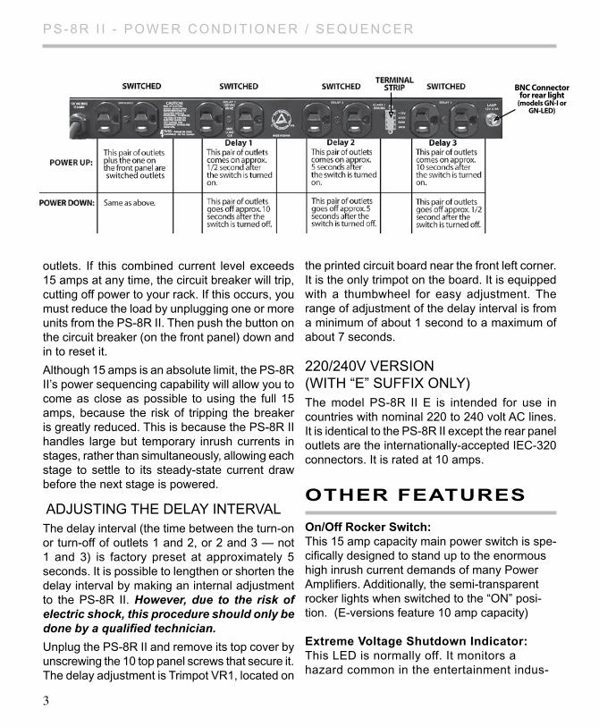
The PS-8R II provides three outlet pairs labeled Delay 1, Delay 2, and Delay 3, that receive power approximately 1/2, 5, and 10 seconds, respec-tively, after the front panel sequence switch is switched to “ON.” When switched to “OFF,” the sequence is reversed, with Delay 3 losing power after approximately 1/2 second, Delay 2 after 5 seconds, and Delay 1 after 10 seconds. See the rear panel illustration on page 3. The turn-on de-lay intervals are factory preset at these durations, but may be altered by means of an internal trimpot adjustment (see “Adjusting the Delay Intervals” for details). In addition to the delayed outlets, a single front panel outlet and a rear panel pair are powered through the main power on/off switch. All rear panel outlets are standard 120V, 15A duplex types.
In the event of a power outage, all equipment plugged into a PS-8R II will lose power simulta-neously. However, when power is restored, the delayed outlet groups will again turn on in the usual delayed sequence.
We recommend that power amps receive power last — plug them all into Delay 3 or divide them into two groups and plug one group into Delay 2 and the other into Delay 3. Low level equipment such as mixers and signal processors should use Delay 1.
The overall capacity of the PS-8R II is 15 amps. This refers to the combined steady-state current drawn by all devices plugged into all of its nine
2
PS-8R I I - POWER CONDIT IONER / SEqu ENCER
outlets. If this combined current level exceeds 15 amps at any time, the circuit breaker will trip, cutting off power to your rack. If this occurs, you must reduce the load by unplugging one or more units from the PS-8R II. Then push the button on the circuit breaker (on the front panel) down and in to reset it.
Although 15 amps is an absolute limit, the PS-8R II’s power sequencing capability will allow you to come as close as possible to using the full 15 amps, because the risk of tripping the breaker is greatly reduced. This is because the PS-8R II handles large but temporary inrush currents in stages, rather than simultaneously, allowing each stage to settle to its steady-state current draw before the next stage is powered.
ADjuSTING THE DELAy INTERVALThe delay interval (the time between the turn-on or turn-off of outlets 1 and 2, or 2 and 3 — not 1 and 3) is factory preset at approximately 5 seconds. It is possible to lengthen or shorten the delay interval by making an internal adjustment to the PS-8R II. However, due to the risk of electric shock, this procedure should only be done by a qualified technician.
unplug the PS-8R II and remove its top cover by unscrewing the 10 top panel screws that secure it. The delay adjustment is Trimpot VR1, located on
the printed circuit board near the front left corner. It is the only trimpot on the board. It is equipped with a thumbwheel for easy adjustment. The range of adjustment of the delay interval is from a minimum of about 1 second to a maximum of about 7 seconds.
220/240V VERSION (WITh “E” SuFFIx ONly)The model PS-8R II E is intended for use in countries with nominal 220 to 240 volt AC lines. It is identical to the PS-8R II except the rear panel outlets are the internationally-accepted IEC-320 connectors. It is rated at 10 amps.
other features
on/off rocker switch: This 15 amp capacity main power switch is spe-cifically designed to stand up to the enormous high inrush current demands of many Power Amplifiers. Additionally, the semi-transparent rocker lights when switched to the “ON” posi-tion. (E-versions feature 10 amp capacity)
extreme Voltage shutdown Indicator: This LED is normally off. It monitors a hazard common in the entertainment indus-
BNC Connectorfor rear light
(models GN-I orGN-LED)
switched outlets
3
PS-8R I I - POWER CONDIT IONER / SEqu ENCER
try: wiring faults – for example, accidental connection to 220VAC where 120VAC is expected, or an open neutral from a 208 or 240VAC feed. The Series II SMP+ cir-cuit senses voltages that are so high that operation would be impossible and shuts the power down before damage can occur. upon initially applying power to these units, the Extreme Voltage indicator LED will light if the input voltage is above the extreme voltage cutoff, and power will not be applied to the unit’s outlets. If the unit has been op-erating with an acceptable input voltage and subsequently that voltage exceeds 135V, it will shut off power to the outlet and the Extreme Voltage LED will light. (E version: over voltage shut down is 275 ±5 VAC and guards against open neutral and accidental connection to 300+ VAC)
protection oK Indicator:Although the Furman SMP+ circuit assures protection from transient voltage spikes and surges, nature has a way of occasionally creating electrical forces that are beyond the capabilities of any TVSS device to absorb without some degree of damage. In the rare instance that this occurs, the green “Protection OK” lED indicator located on your front panel will dim. If this happens, some level of protection from voltage surges will remain, but the Furman’s clamping voltage rating will be compromised. The unit must be returned to Furman Sound, or an authorized Furman service center for repair. NOTE: If the mains power is above the high cutoff voltage and has caused the unit to re-move power from its outlets, it cannot restore power without the operator manually turning the unit off, then on again. Avoid turning the unit back on, without first checking the source of the problem, and perhaps changing the AC source.
All Series II units feature a rear rack BNC socket which will accept any 12 VAC (0.5A) gooseneck lamp assembly, (such as the Fur-man GN-LED or GN-I). Simply slide the BNC plug over the socket and rotate clockwise until the connector snaps into the locked position. The rear rack lamp can be powered on or off with the rear light power switch located on the far left of the front panel. The Series II’s front panel lED lamps must be replaced by qualified
Furman service personnel.
reMote swItchIng
(PS-8R II & PS-8R II E)In the most basic configuration, only two wires and an SPST switch are needed to initiate remote ON or OFF sequence. The switch may be either a momentary or maintained-contact type. If a third & fourth wire are used, an LED may also be installed at the remote end to indicate that the power is on.
MAINTAINED VS. MOMENTARy CONTACT SWITCHING
Maintained switches, such as most toggle switches and push-on/push-off switches (including the Furman RS-1), stay open until switched and then remain closed until switched again.
Momentary switches, usually pushbutton types like the Furman RS-2, are normally open and stay closed only as long as the button is pressed. An on-off switch of either kind may be used to actuate the PS-8R II’s remote operation.
Maintained switches are generally most convenient when there is only one remote location. When more than one switch location is required, momentary switches allow the sequence to be started from different locations.
PS-8R II main circuit board has 5 pairs of terminals (PCB REV F and later) labeled as:
4
PS-8R I I - POWER CONDIT IONER / SEqu ENCER
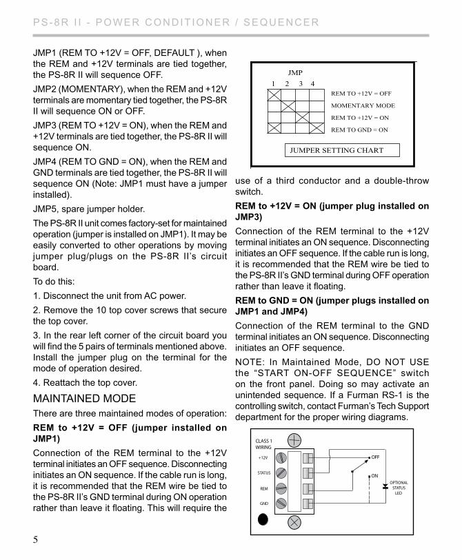
JMP1 (REM TO +12V = OFF, DEFAuLT ), when the REM and +12V terminals are tied together, the PS-8R II will sequence OFF.
jMP2 (MOMENTARy), when the REM and +12V terminals are momentary tied together, the PS-8R II will sequence ON or OFF.
JMP3 (REM TO +12V = ON), when the REM and +12V terminals are tied together, the PS-8R II will sequence ON.
JMP4 (REM TO GND = ON), when the REM and GND terminals are tied together, the PS-8R II will sequence ON (Note: jMP1 must have a jumper installed).
jMP5, spare jumper holder.
The PS-8R II unit comes factory-set for maintained operation (jumper is installed on jMP1). It may be easily converted to other operations by moving jumper plug/plugs on the PS-8R II’s circuit board.
To do this:
1. Disconnect the unit from AC power.
2. Remove the 10 top cover screws that secure the top cover.
3. In the rear left corner of the circuit board you will find the 5 pairs of terminals mentioned above. Install the jumper plug on the terminal for the mode of operation desired.
4. Reattach the top cover.
MAINTAINED MODEThere are three maintained modes of operation:
reM to +12V = off (jumper installed on JMp1)
Connection of the REM terminal to the +12V terminal initiates an OFF sequence. Disconnecting initiates an ON sequence. If the cable run is long, it is recommended that the REM wire be tied to the PS-8R II’s GND terminal during ON operation rather than leave it floating. This will require the
use of a third conductor and a double-throw switch.
reM to +12V = on (jumper plug installed on JMp3)
Connection of the REM terminal to the +12V terminal initiates an ON sequence. Disconnecting initiates an OFF sequence. If the cable run is long, it is recommended that the REM wire be tied to the PS-8R II’s GND terminal during OFF operation rather than leave it floating.
reM to gnd = on (jumper plugs installed on JMp1 and JMp4)
Connection of the REM terminal to the GND terminal initiates an ON sequence. Disconnecting initiates an OFF sequence.
NOTE: In Maintained Mode, DO NOT uSE the “START ON-OFF SEQuENCE” switch on the front panel. Doing so may activate an unintended sequence. If a Furman RS-1 is the controlling switch, contact Furman’s Tech Support department for the proper wiring diagrams.
5
CLASS 1WIRING
+12V
STATUS
REM
GND
OPTIONALSTATUS
LED
OFF
ON
JMP
REM TO +12V = OFF
MOMENTARY MODE
REM TO +12V = ON
REM TO GND = ON
1 2 3 4
JUMPER SETTING CHART
PS-8R I I - POWER CONDIT IONER / SEqu ENCER
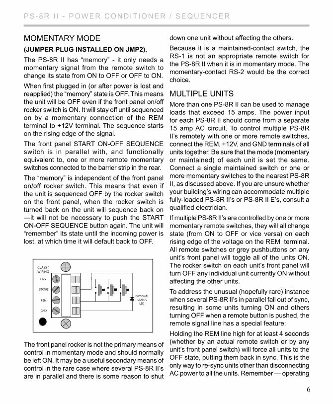
MOMENTARy MODE (JuMper plug Installed on JMp2).
The PS-8R II has “memory” - it only needs a momentary signal from the remote switch to change its state from ON to OFF or OFF to ON.
When first plugged in (or after power is lost and reapplied) the “memory” state is OFF. This means the unit will be OFF even if the front panel on/off rocker switch is ON. It will stay off until sequenced on by a momentary connection of the REM terminal to +12V terminal. The sequence starts on the rising edge of the signal.
The front panel START ON-OFF SEquENCE switch is in parallel with, and functionally equivalent to, one or more remote momentary switches connected to the barrier strip in the rear.
The “memory” is independent of the front panel on/off rocker switch. This means that even if the unit is sequenced OFF by the rocker switch on the front panel, when the rocker switch is turned back on the unit will sequence back on —it will not be necessary to push the START ON-OFF SEquENCE button again. The unit will “remember” its state until the incoming power is lost, at which time it will default back to OFF.
The front panel rocker is not the primary means of control in momentary mode and should normally be left ON. It may be a useful secondary means of control in the rare case where several PS-8R II’s are in parallel and there is some reason to shut
down one unit without affecting the others.
Because it is a maintained-contact switch, the RS-1 is not an appropriate remote switch for the PS-8R II when it is in momentary mode. The momentary-contact RS-2 would be the correct choice.
MuLTIPLE uNITSMore than one PS-8R II can be used to manage loads that exceed 15 amps. The power input for each PS-8R II should come from a separate 15 amp AC circuit. To control multiple PS-8R II’s remotely with one or more remote switches, connect the REM, +12V, and GND terminals of all units together. Be sure that the mode (momentary or maintained) of each unit is set the same. Connect a single maintained switch or one or more momentary switches to the nearest PS-8R II, as discussed above. If you are unsure whether your building’s wiring can accommodate multiple fully-loaded PS-8R II’s or PS-8R II E’s, consult a qualified electrician.
If multiple PS-8R II’s are controlled by one or more momentary remote switches, they will all change state (from ON to OFF or vice versa) on each rising edge of the voltage on the REM terminal. All remote switches or grey pushbuttons on any unit’s front panel will toggle all of the units ON. The rocker switch on each unit’s front panel will turn OFF any individual unit currently ON without affecting the other units.
To address the unusual (hopefully rare) instance when several PS-8R II’s in parallel fall out of sync, resulting in some units turning ON and others turning OFF when a remote button is pushed, the remote signal line has a special feature:
Holding the REM line high for at least 4 seconds (whether by an actual remote switch or by any unit’s front panel switch) will force all units to the OFF state, putting them back in sync. This is the only way to re-sync units other than disconnecting AC power to all the units. Remember — operating
6
CLASS 1WIRING
+12V
STATUS
REM
GND
OPTIONALSTATUS
LED
PS-8R I I - POWER CONDIT IONER / SEqu ENCER
the front panel rocker switch does NOT affect the stored state of the unit, even though it does temporarily turn the outputs OFF.
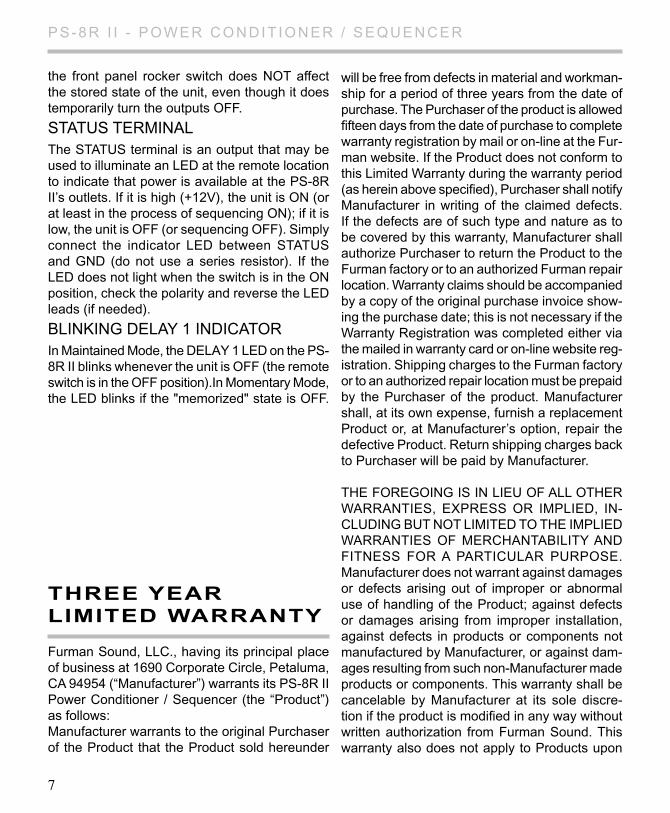
STATuS TERMINAL
The STATuS terminal is an output that may be used to illuminate an LED at the remote location to indicate that power is available at the PS-8R II’s outlets. If it is high (+12V), the unit is ON (or at least in the process of sequencing ON); if it is low, the unit is OFF (or sequencing OFF). Simply connect the indicator LED between STATuS and GND (do not use a series resistor). If the LED does not light when the switch is in the ON position, check the polarity and reverse the LED leads (if needed).
BLINKING DELAy 1 INDICATORIn Maintained Mode, the DELAy 1 LED on the PS-8R II blinks whenever the unit is OFF (the remote switch is in the OFF position).In Momentary Mode, the LED blinks if the "memorized" state is OFF.
7
three year lIMIted warranty
Furman Sound, LLC., having its principal place of business at 1690 Corporate Circle, Petaluma, CA 94954 (“Manufacturer”) warrants its PS-8R II Power Conditioner / Sequencer (the “Product”) as follows:Manufacturer warrants to the original Purchaser of the Product that the Product sold hereunder
will be free from defects in material and workman-ship for a period of three years from the date of purchase. The Purchaser of the product is allowed fifteen days from the date of purchase to complete warranty registration by mail or on-line at the Fur-man website. If the Product does not conform to this Limited Warranty during the warranty period (as herein above specified), Purchaser shall notify Manufacturer in writing of the claimed defects. If the defects are of such type and nature as to be covered by this warranty, Manufacturer shall authorize Purchaser to return the Product to the Furman factory or to an authorized Furman repair location. Warranty claims should be accompanied by a copy of the original purchase invoice show-ing the purchase date; this is not necessary if the Warranty Registration was completed either via the mailed in warranty card or on-line website reg-istration. Shipping charges to the Furman factory or to an authorized repair location must be prepaid by the Purchaser of the product. Manufacturer shall, at its own expense, furnish a replacement Product or, at Manufacturer’s option, repair the defective Product. Return shipping charges back to Purchaser will be paid by Manufacturer.
THE FOREGOING IS IN LIEu OF ALL OTHER WARRANTIES, ExPRESS OR IMPlIED, IN-CLuDING BuT NOT LIMITED TO THE IMPLIED WARRANTIES OF MERCHANTABILITy AND FITNESS FOR A PARTICuLAR PuRPOSE. Manufacturer does not warrant against damages or defects arising out of improper or abnormal use of handling of the Product; against defects or damages arising from improper installation, against defects in products or components not manufactured by Manufacturer, or against dam-ages resulting from such non-Manufacturer made products or components. This warranty shall be cancelable by Manufacturer at its sole discre-tion if the product is modified in any way without written authorization from Furman Sound. This warranty also does not apply to Products upon
PS-8R I I - POWER CONDIT IONER / SEqu ENCER
8
serVIce
Before returning any equipment for repair, please be sure that it is adequately packed and cush-ioned against damage in shipment, and that it is insured. We suggest that you save the original packaging and use it to ship the product for ser-vicing. Also, please enclose a note giving your name, address, phone number and a description of the problem.
NOTE: All equipment being returned for repair must have a Return Authorization (RA) Number. To get an RA Number, please call the Furman Service Department, (707) 763-1010, Ext. 2370 or 2377, between 8 am and 5 pm u.S. Pacific Time. Please display your RA Number prominently on the front of all packages.
which repairs have been affected or attempted by persons other than pursuant to written authoriza-tion by Manufacturer.
ThIS WARRANTy IS ExCluSIVE. The sole and exclusive obligation of Manufacturer shall be to repair or replace the defective Product in the manner and for the period provided above. Manufacturer shall not have any other obligation with respect to the Products or any part thereof, whether based on contract, tort, strict liability or otherwise. under no circumstances, whether based on this Limited Warranty or otherwise, shall Manufacturer be liable for incidental, spe-cial, or consequential damages. Manufacturer’s employees or representatives’ ORAL OR OTHER WRITTEN STATEMENTS DO NOT CONSTI-TuTE WARRANTIES, shall not be relied upon by Purchaser, and are not a part of the contract for sale or this limited warranty. This Limited Warranty states the entire obligation of Manufacturer with respect to the Product. If any part of this Limited Warranty is determined to be void or illegal, the remainder shall remain in full force and effect.
PS-8R I I - POWER CONDIT IONER / SEqu ENCER
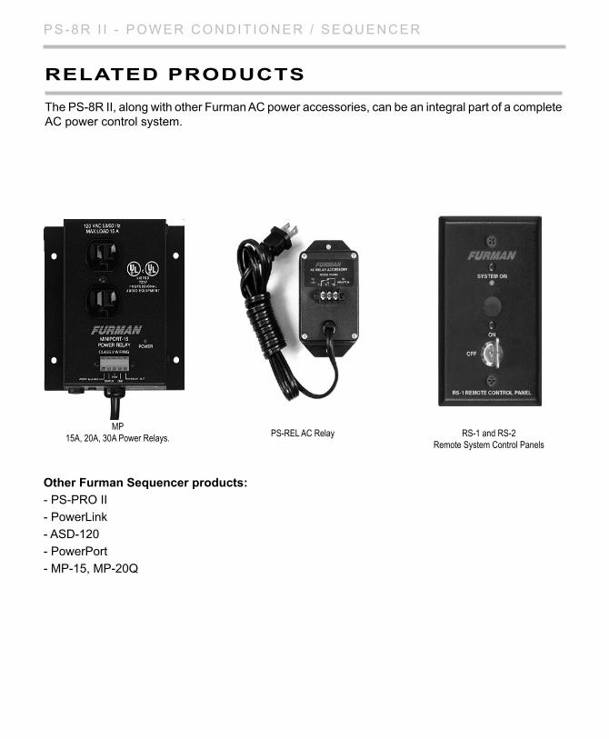
PS-REL AC RelayMP
15A, 20A, 30A Power Relays. RS-1 and RS-2Remote System Control Panels
related products
The PS-8R II, along with other Furman AC power accessories, can be an integral part of a complete AC power control system.
other furman sequencer products:
- PS-PRO II
- PowerLink
- ASD-120
- PowerPort
- MP-15, MP-20q
PS-8R I I - POWER CONDIT IONER / SEqu ENCER
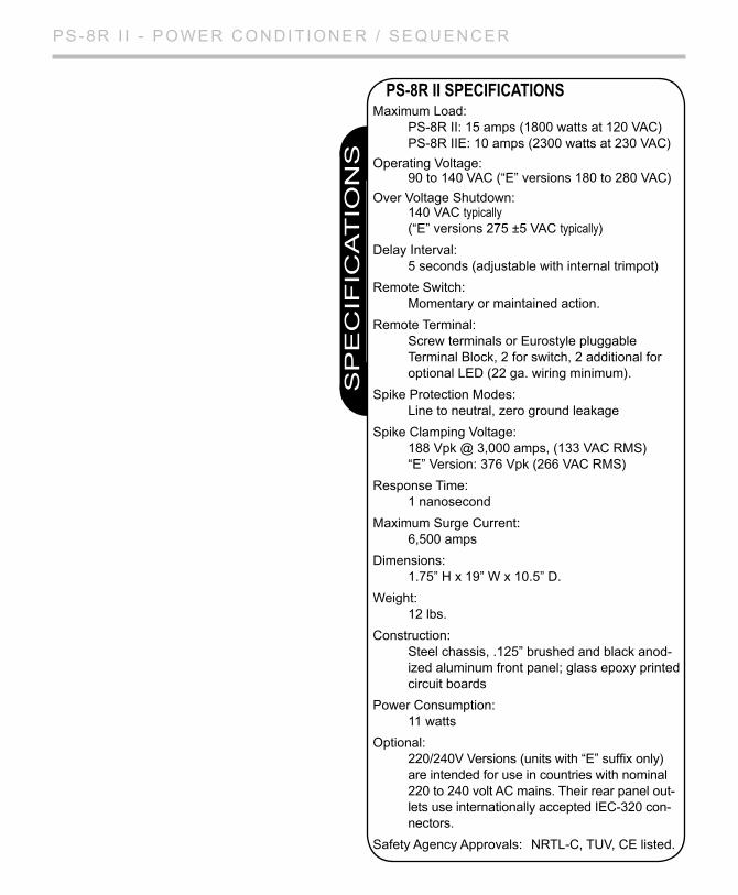
Maximum Load: PS-8R II: 15 amps (1800 watts at 120 VAC) PS-8R IIE: 10 amps (2300 watts at 230 VAC)
Operating Voltage: 90 to 140 VAC (“E” versions 180 to 280 VAC)
Over Voltage Shutdown: 140 VAC typically (“E” versions 275 ±5 VAC typically)
Delay Interval: 5 seconds (adjustable with internal trimpot)
Remote Switch: Momentary or maintained action.
Remote Terminal: Screw terminals or Eurostyle pluggable Terminal Block, 2 for switch, 2 additional for optional LED (22 ga. wiring minimum).
Spike Protection Modes: Line to neutral, zero ground leakage
Spike Clamping Voltage: 188 Vpk @ 3,000 amps, (133 VAC RMS) “E” Version: 376 Vpk (266 VAC RMS)
Response Time: 1 nanosecond
Maximum Surge Current: 6,500 amps
Dimensions: 1.75” h x 19” W x 10.5” D.
Weight: 12 lbs.
Construction: Steel chassis, .125” brushed and black anod- ized aluminum front panel; glass epoxy printed circuit boards
Power Consumption: 11 watts
Optional: 220/240V Versions (units with “E” suffix only) are intended for use in countries with nominal 220 to 240 volt AC mains. Their rear panel out- lets use internationally accepted IEC-320 con- nectors.
Safety Agency Approvals: NRTL-C, TuV, CE listed.
PS-8R II SPECIFICATIONS
SP
EC
IFIC
AT
ION
S

PS-8R I I - POWER CONDIT IONER / SEqu ENCER
Furman Sound, LLC.1690 Corporate Circle
Petaluma, California 94954-6919 uSAPhone: 707-763-1010 Fax: 707-763-1310
Web: www.FurmanSound.com E-mail: [email protected]