prx nprox proximity multi function reader installer manual...
TRANSCRIPT

Nano PROX
Proximity Card Reader
Installation Manual

PUBLICATION INFORMATION 504A R Final Release
1 Nano Prox™ Proximity Reader Installer
CONTENTS
1.0 INTRODUCTION ........................ 2 1.1 Legend ............................................................. 2.2 Terminology .....................................................
2.0 MOUNTING ............................ 3.0 WIEGAND CONNECTION ............. 4.0 AUX BUTTON INPUT ............... 5.0 INSTALLER PROGRAMMING ....... 5.1 Entering Program Mode ................................................ 5.2 Address Selection ..................................................... 5.3 Data Programming ..................................................
6.0 USER PROGRAMMING ............... 6.1 Entering User Program Mode ...................................... 6.2 Address Selection .....................................................
7.0 SPECIFICATIONS ...................... 8.0 WARRANTY .............................
4 5 5
7 8
10 11
11 11 12
19 19 19
22 23

2 Nano Prox™ Proximity Reader Installer Manual
1.0 INTRODUCTION
Thank you for choosing the Nano Prox Proximity Reader from Integrated Control Technology. The Nano Prox Proximity Reader is an advanced technology radio frequency identification device (RFID) specifically designed to enhance the functionality of security, building automation and access control by providing multiple format compatibility, high speed data transmission, built in stand alone operation and sabotage protection. The Nano Prox Proximity Reader is designed to operate as a Normal Wiegand Proximity Reader or as a complete Standalone Single Door Controller. The Nano Prox Proximity Reader can be programmed to perform and operate using different card and data output formats. Therefore, before installing the Nano Prox Proximity Reader, we highly recommend you read this manual carefully and ensure that the data formats you program will operate with the configured access control or security product. When operating the Nano Prox Proximity Reader in stand alone mode we recommend using the Nano Prox Access Manager Application which allows a personal computer to perform user programming and configuration. For more information on the Nano Prox Proximity Reader and other Integrated Control Technology products please login to www.integratedcontroltechnology.com
3 Nano Prox™ Proximity Reader Installer
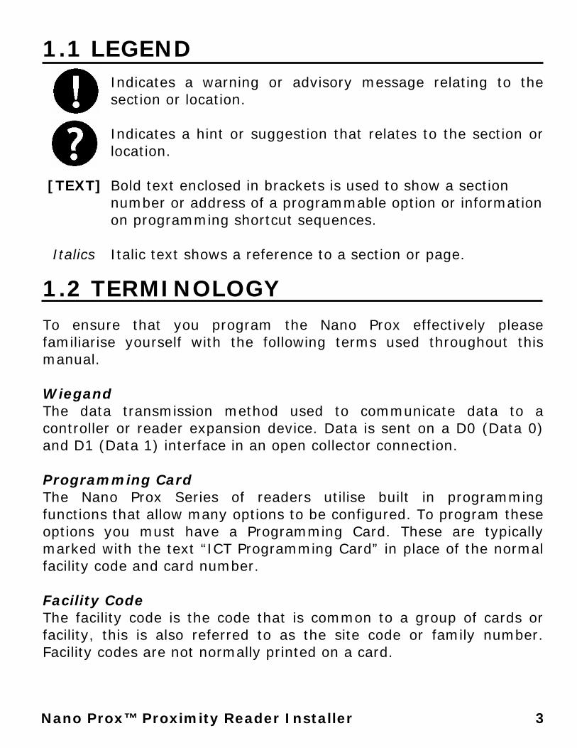
1.1 LEGEND
Indicates a warning or advisory message relating to the section or location. Indicates a hint or suggestion that relates to the section or location.
[TEXT] Bold text enclosed in brackets is used to show a section
number or address of a programmable option or information on programming shortcut sequences.
Italics Italic text shows a reference to a section or page.
1.2 TERMINOLOGY
To ensure that you program the Nano Prox effectively please familiarise yourself with the following terms used throughout this manual. Wiegand The data transmission method used to communicate data to a controller or reader expansion device. Data is sent on a D0 (Data 0) and D1 (Data 1) interface in an open collector connection. Programming Card The Nano Prox Series of readers utilise built in programming functions that allow many options to be configured. To program these options you must have a Programming Card. These are typically marked with the text “ICT Programming Card” in place of the normal facility code and card number. Facility Code The facility code is the code that is common to a group of cards or facility, this is also referred to as the site code or family number. Facility codes are not normally printed on a card.
4 Nano Prox™ Proximity Reader Installer Manual
Card Number The card number identifies the card to the system, the card number is printed in the lower right of the card or across the back of the tag. Pre Alarm Time When the door contact is opened during the door unlock time a pre-alarm warning will be sounded after the pre alarm time has expired to indicate the door left open alarm will be generated. Door Left Open Time When the door contact is left open during the door unlock time the beeper will be sounded continuously after the time has expired to indicate the door has been left open. Closing the door silences the Door Left Open Alarm. REX (Request To Exit) The REX or Request To Exit input is used to exit a door, the input can be connected to a exit detector, push button or other egress device to allow free exit of the door. Master User A Master User is a standalone user who is able to program users in to the Nano Prox Proximity Reader to allow them to access the door. Any number of Master Users can be programmed in the Nano Prox Proximity Reader.

5 Nano Prox™ Proximity Reader Installer
2.0 MOUNTING
When mounting the Nano Prox Proximity Reader please respect the following guidelines.
• Avoid wiring the Nano Prox cables in the same conduit with AC power cables, lock power, or signal wiring.
• Maintain all reader wiring a minimum of 12" (30cm) away from other wiring such as AC power, computer data wiring, telephone wiring and wiring to electric lock devices.
• Avoid installing within 3.5 feet (1.1m) of computer monitors or CRTs. The minimum distance will vary depending on the type of monitor or CRT.
• Avoid installing in proximity to sources of broad spectrum EMI noise such as motors, pumps, generators, DC to AC converters, uninterruptible power supplies, AC switching relays, light dimmers, computer monitors and CRTs.
• Avoid installing in proximity to potential sources of high power RF signal transmitters such as cellular telephones and two way radios.
6 Nano Prox™ Proximity Reader Installer Manual
3.0 WIEGAND CONNECTION
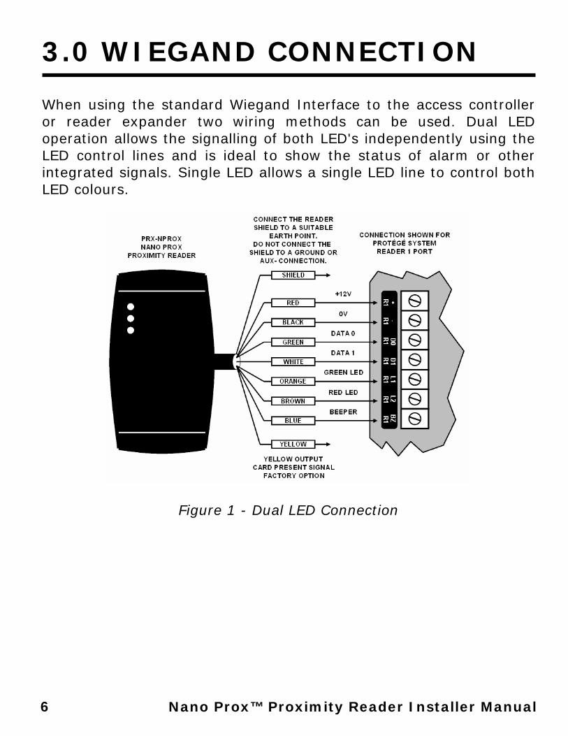
When using the standard Wiegand Interface to the access controller or reader expander two wiring methods can be used. Dual LED operation allows the signalling of both LED's independently using the LED control lines and is ideal to show the status of alarm or other integrated signals. Single LED allows a single LED line to control both LED colours.
Figure 1 - Dual LED Connection
7 Nano Prox™ Proximity Reader Installer
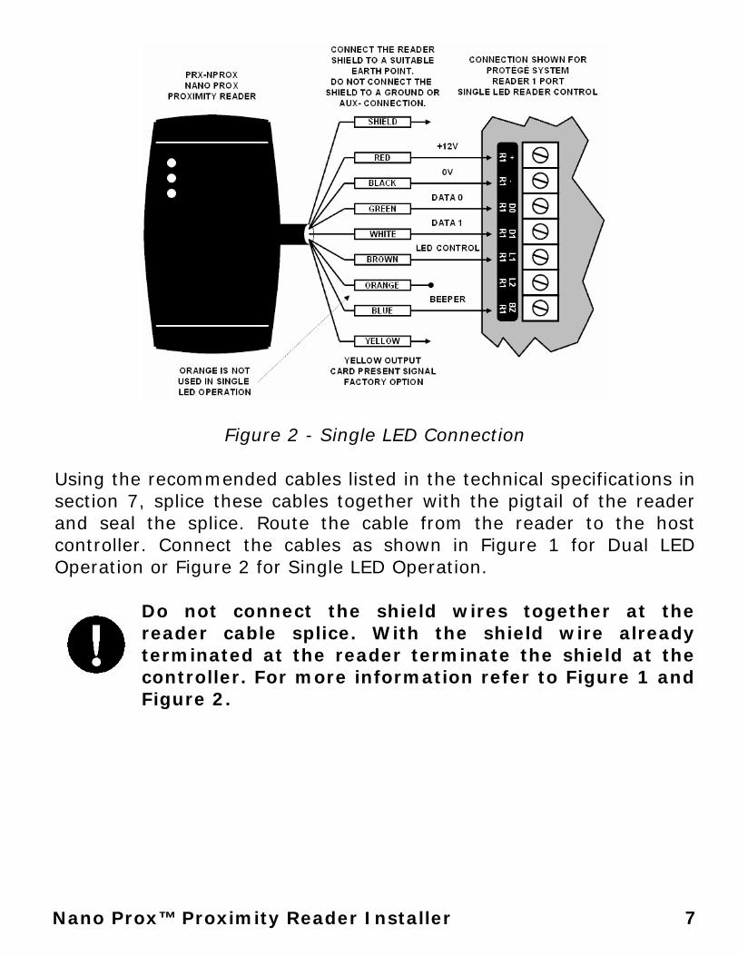
Figure 2 - Single LED Connection Using the recommended cables listed in the technical specifications in section 7, splice these cables together with the pigtail of the reader and seal the splice. Route the cable from the reader to the host controller. Connect the cables as shown in Figure 1 for Dual LED Operation or Figure 2 for Single LED Operation.
Do not connect the shield wires together at the reader cable splice. With the shield wire already terminated at the reader terminate the shield at the controller. For more information refer to Figure 1 and Figure 2.
8 Nano Prox™ Proximity Reader Installer Manual
4.0 AUX BUTTON INPUT
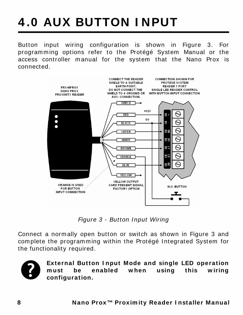
Button input wiring configuration is shown in Figure 3. For programming options refer to the Protégé System Manual or the access controller manual for the system that the Nano Prox is connected.
Figure 3 - Button Input Wiring Connect a normally open button or switch as shown in Figure 3 and complete the programming within the Protégé Integrated System for the functionality required.
External Button Input Mode and single LED operation must be enabled when using this wiring configuration.

9 Nano Prox™ Proximity Reader Installer
5.0 INSTALLER PROGRAMMING
By default the Nano Prox Proximity Reader is factory configured to send data in 26 Bit Wiegand Format, it will read all card formats and operate in the dual LED line mode. This configuration can be changed to suit system operating requirements. Programming is completed by presenting a programming card to the unit within the first 2 minutes of power being applied. For information on standalone and end user programming options refer to User Programming Section on Page 17.
The programming card can only be presented within the first 2 minutes from when the card reader powers up.
5.1 ENTERING PROGRAM MODE
To program the Card Reader badge the programming card once, the Card Reader will beep to indicate the card has been read and then beep twice and illuminate the RED LED to indicate programming mode has been entered.
5.2 ADDRESS SELECTION To select an address to program the programming card is presented to the card reader the number of times matching the address number.
Address Programming Option 1 Card Reading Format 2 Data Output Format 3 LED Configuration 4 Intelligent Tamper Mode 5 Auxiliary Button Input Mode
10 Nano Prox™ Proximity Reader Installer Manual
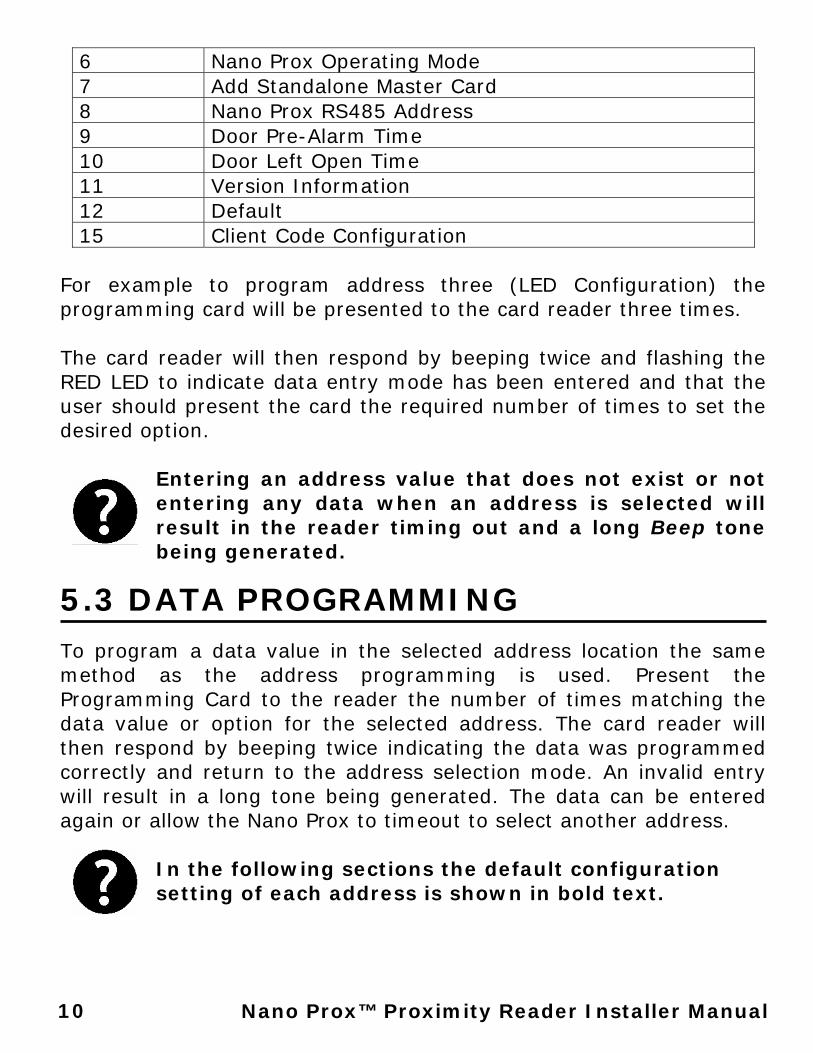
6 Nano Prox Operating Mode 7 Add Standalone Master Card 8 Nano Prox RS485 Address 9 Door Pre-Alarm Time 10 Door Left Open Time 11 Version Information 12 Default 15 Client Code Configuration
For example to program address three (LED Configuration) the programming card will be presented to the card reader three times. The card reader will then respond by beeping twice and flashing the RED LED to indicate data entry mode has been entered and that the user should present the card the required number of times to set the desired option.
Entering an address value that does not exist or not entering any data when an address is selected will result in the reader timing out and a long Beep tone being generated.
5.3 DATA PROGRAMMING
To program a data value in the selected address location the same method as the address programming is used. Present the Programming Card to the reader the number of times matching the data value or option for the selected address. The card reader will then respond by beeping twice indicating the data was programmed correctly and return to the address selection mode. An invalid entry will result in a long tone being generated. The data can be entered again or allow the Nano Prox to timeout to select another address.
In the following sections the default configuration setting of each address is shown in bold text.
11 Nano Prox™ Proximity Reader Installer
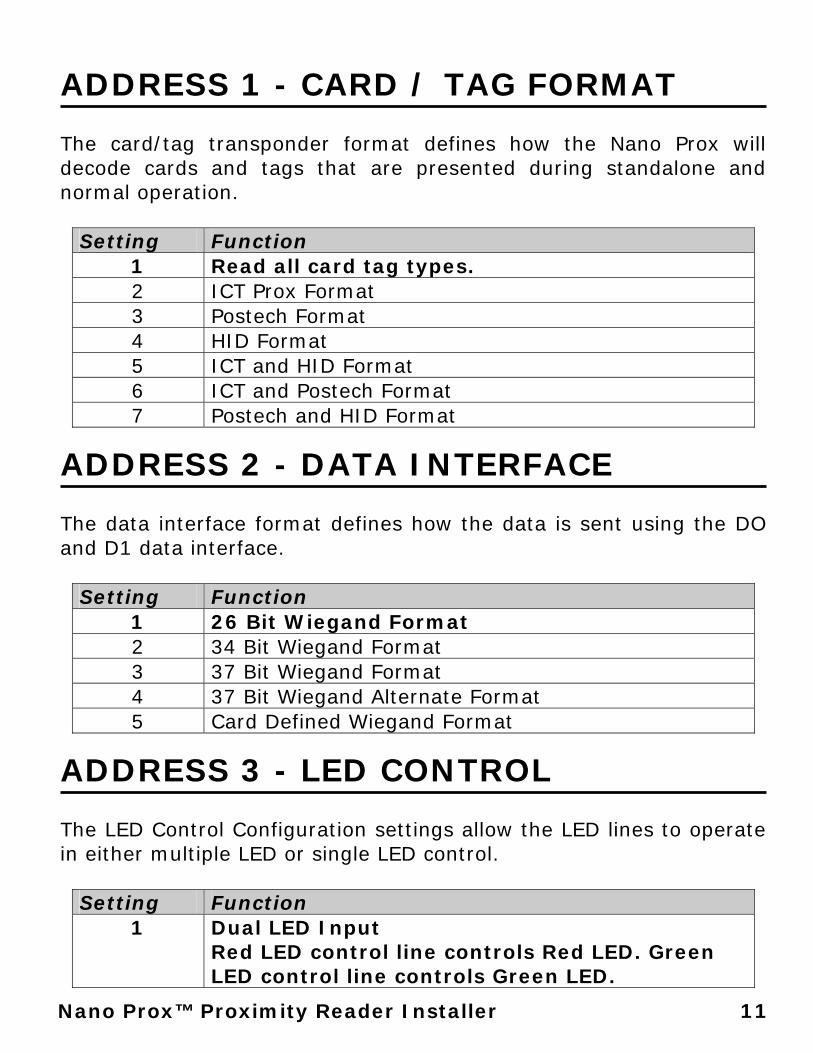
ADDRESS 1 - CARD / TAG FORMAT The card/tag transponder format defines how the Nano Prox will decode cards and tags that are presented during standalone and normal operation.
Setting Function 1 Read all card tag types. 2 ICT Prox Format 3 Postech Format 4 HID Format 5 ICT and HID Format 6 ICT and Postech Format 7 Postech and HID Format
ADDRESS 2 - DATA INTERFACE The data interface format defines how the data is sent using the DO and D1 data interface.
Setting Function 1 26 Bit Wiegand Format 2 34 Bit Wiegand Format 3 37 Bit Wiegand Format 4 37 Bit Wiegand Alternate Format 5 Card Defined Wiegand Format
ADDRESS 3 - LED CONTROL The LED Control Configuration settings allow the LED lines to operate in either multiple LED or single LED control.
Setting Function 1 Dual LED Input
Red LED control line controls Red LED. Green LED control line controls Green LED.
12 Nano Prox™ Proximity Reader Installer Manual
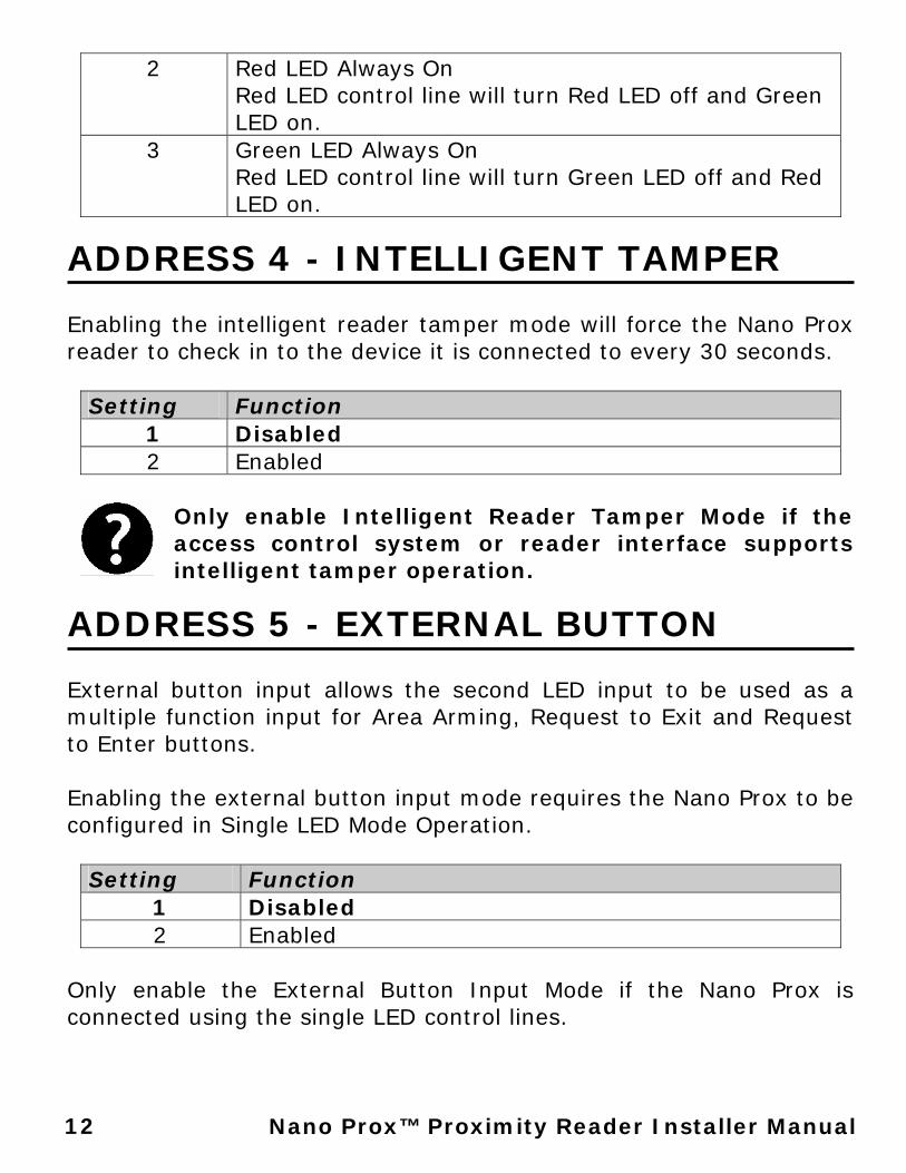
2 Red LED Always On Red LED control line will turn Red LED off and Green LED on.
3 Green LED Always On Red LED control line will turn Green LED off and Red LED on.
ADDRESS 4 - INTELLIGENT TAMPER Enabling the intelligent reader tamper mode will force the Nano Prox reader to check in to the device it is connected to every 30 seconds.
Setting Function 1 Disabled 2 Enabled
Only enable Intelligent Reader Tamper Mode if the access control system or reader interface supports intelligent tamper operation.
ADDRESS 5 - EXTERNAL BUTTON External button input allows the second LED input to be used as a multiple function input for Area Arming, Request to Exit and Request to Enter buttons. Enabling the external button input mode requires the Nano Prox to be configured in Single LED Mode Operation.
Setting Function 1 Disabled 2 Enabled
Only enable the External Button Input Mode if the Nano Prox is connected using the single LED control lines.
13 Nano Prox™ Proximity Reader Installer
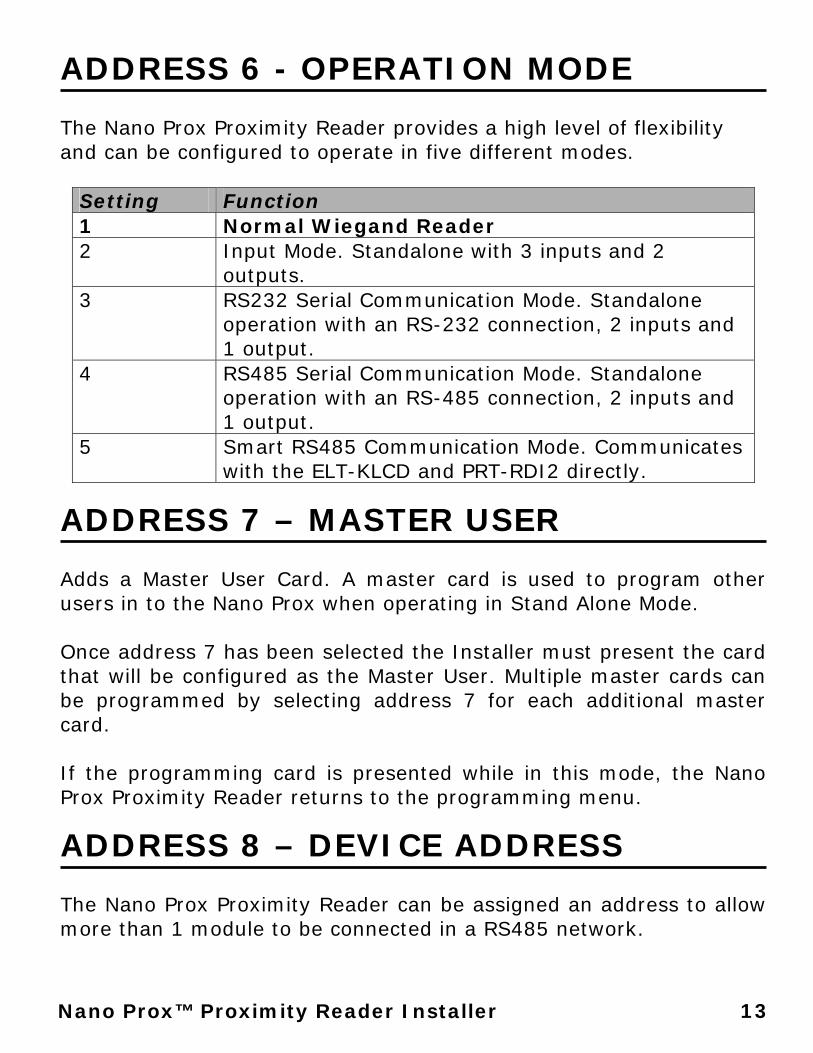
ADDRESS 6 - OPERATION MODE The Nano Prox Proximity Reader provides a high level of flexibility and can be configured to operate in five different modes.
Setting Function 1 Normal Wiegand Reader 2 Input Mode. Standalone with 3 inputs and 2
outputs. 3 RS232 Serial Communication Mode. Standalone
operation with an RS-232 connection, 2 inputs and 1 output.
4 RS485 Serial Communication Mode. Standalone operation with an RS-485 connection, 2 inputs and 1 output.
5 Smart RS485 Communication Mode. Communicates with the ELT-KLCD and PRT-RDI2 directly.
ADDRESS 7 – MASTER USER Adds a Master User Card. A master card is used to program other users in to the Nano Prox when operating in Stand Alone Mode. Once address 7 has been selected the Installer must present the card that will be configured as the Master User. Multiple master cards can be programmed by selecting address 7 for each additional master card. If the programming card is presented while in this mode, the Nano Prox Proximity Reader returns to the programming menu.
ADDRESS 8 – DEVICE ADDRESS The Nano Prox Proximity Reader can be assigned an address to allow more than 1 module to be connected in a RS485 network.
14 Nano Prox™ Proximity Reader Installer Manual
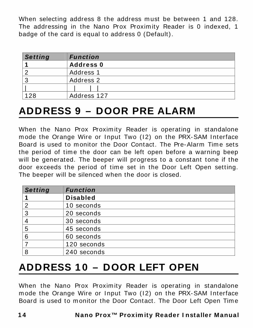
When selecting address 8 the address must be between 1 and 128. The addressing in the Nano Prox Proximity Reader is 0 indexed, 1 badge of the card is equal to address 0 (Default).
Setting Function 1 Address 0 2 Address 1 3 Address 2 | | | | 128 Address 127
ADDRESS 9 – DOOR PRE ALARM When the Nano Prox Proximity Reader is operating in standalone mode the Orange Wire or Input Two (I2) on the PRX-SAM Interface Board is used to monitor the Door Contact. The Pre-Alarm Time sets the period of time the door can be left open before a warning beep will be generated. The beeper will progress to a constant tone if the door exceeds the period of time set in the Door Left Open setting. The beeper will be silenced when the door is closed.
Setting Function 1 Disabled 2 10 seconds 3 20 seconds 4 30 seconds 5 45 seconds 6 60 seconds 7 120 seconds 8 240 seconds
ADDRESS 10 – DOOR LEFT OPEN When the Nano Prox Proximity Reader is operating in standalone mode the Orange Wire or Input Two (I2) on the PRX-SAM Interface Board is used to monitor the Door Contact. The Door Left Open Time
15 Nano Prox™ Proximity Reader Installer
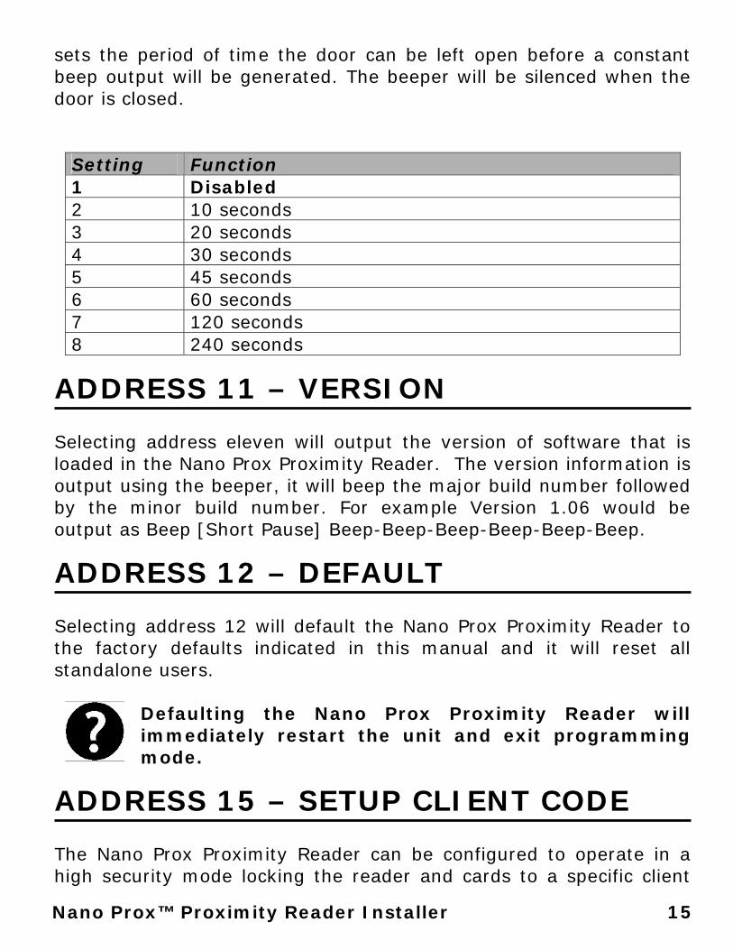
sets the period of time the door can be left open before a constant beep output will be generated. The beeper will be silenced when the door is closed.
Setting Function 1 Disabled 2 10 seconds 3 20 seconds 4 30 seconds 5 45 seconds 6 60 seconds 7 120 seconds 8 240 seconds
ADDRESS 11 – VERSION Selecting address eleven will output the version of software that is loaded in the Nano Prox Proximity Reader. The version information is output using the beeper, it will beep the major build number followed by the minor build number. For example Version 1.06 would be output as Beep [Short Pause] Beep-Beep-Beep-Beep-Beep-Beep.
ADDRESS 12 – DEFAULT Selecting address 12 will default the Nano Prox Proximity Reader to the factory defaults indicated in this manual and it will reset all standalone users.
Defaulting the Nano Prox Proximity Reader will immediately restart the unit and exit programming mode.
ADDRESS 15 – SETUP CLIENT CODE The Nano Prox Proximity Reader can be configured to operate in a high security mode locking the reader and cards to a specific client
16 Nano Prox™ Proximity Reader Installer Manual
code. Once this address has been selected you must present a valid ICT Client Programming card to set client code for the Nano Prox Proximity Reader.
Setting this option will only allow cards with a valid client code for the card reader to be read. It is also recommended to set the Card/Tag Format (Address 1) to ICT Format to prevent other card formats from being read.
17 Nano Prox™ Proximity Reader Installer
6.0 USER PROGRAMMING
The user address settings are for programming end user options and user cards in to the Nano Prox Proximity Reader when operating in standalone mode. The Master(s) have programming privileges to manage users and end user configuration options in the system.
6.1 ENTERING USER PROGRAM MODE
To access programming mode the Master User must hold down the REX (Request To Exit) Button and present their card. The Nano Prox will respond with 2 beeps to acknowledge that programming mode has been entered. For information on standalone and end user programming options refer to User Programming Section on Page 17.
To enter programming mode the master card can only be presented when the REX (Request To Exit) Button is pressed.
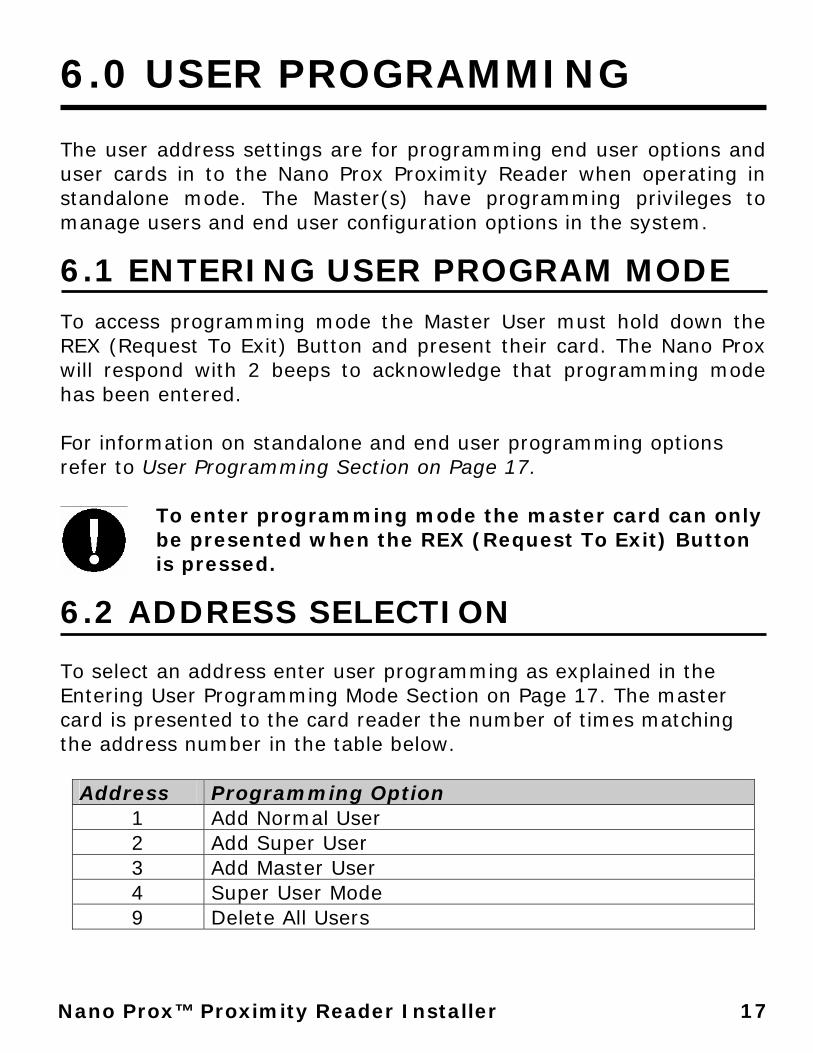
6.2 ADDRESS SELECTION To select an address enter user programming as explained in the Entering User Programming Mode Section on Page 17. The master card is presented to the card reader the number of times matching the address number in the table below.
Address Programming Option 1 Add Normal User 2 Add Super User 3 Add Master User 4 Super User Mode 9 Delete All Users
18 Nano Prox™ Proximity Reader Installer Manual
For example to program address two (Add Super User) the Master Card card will be presented to the card reader two times. The card reader will then respond by beeping twice and flashing the RED LED to indicate data entry mode has been entered and that the user should present the card to program as a super user.
Entering an address value that does not exist or not entering any data when an address is selected will result in the reader timing out and a long Beep tone being generated.
ADDRESS 1 – ADD USER A normal user can only unlock the door for the default five second unlock time. To program a normal user select address one, the Nano Prox Proximity Reader will emit two beeps and then flash the RED LED, present the user card to add in to the Nano Prox. The Nano Prox will emit two beeps to indicate it has programmed the User in the next available location.
ADDRESS 2 – ADD SUPER USER A super user is able to unlock the door for the default five second unlock time and also toggle the super user lock control mode if it is programmed by presenting the card three times to the unit. To program a super user select address two, the Nano Prox Proximity Reader will emit two beeps and then flash the RED LED, present the user card to add in to the Nano Prox. The Nano Prox will emit two beeps to indicate it has programmed the Super User in the next available location.
ADDRESS 3 – ADD MASTER USER A master user is able to unlock the door for the default five second unlock time, add users and toggle the super user lock control mode if it is programmed by presenting the card three times to the unit. To
19 Nano Prox™ Proximity Reader Installer
program a master user select address three, the Nano Prox Proximity Reader will emit two beeps and then flash the RED LED, present the user card to add in to the Nano Prox. The Nano Prox will emit two beeps to indicate it has programmed the Master User in the next available location.
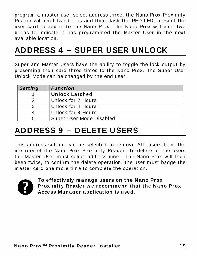
ADDRESS 4 – SUPER USER UNLOCK Super and Master Users have the ability to toggle the lock output by presenting their card three times to the Nano Prox. The Super User Unlock Mode can be changed by the end user.
Setting Function 1 Unlock Latched 2 Unlock for 2 Hours 3 Unlock for 4 Hours 4 Unlock for 8 Hours 5 Super User Mode Disabled
ADDRESS 9 – DELETE USERS This address setting can be selected to remove ALL users from the memory of the Nano Prox Proximity Reader. To delete all the users the Master User must select address nine. The Nano Prox will then beep twice, to confirm the delete operation, the user must badge the master card one more time to complete the operation.
To effectively manage users on the Nano Prox Proximity Reader we recommend that the Nano Prox Access Manager application is used.
20 Nano Prox™ Proximity Reader Installer Manual
7.0 SPECIFICATIONS
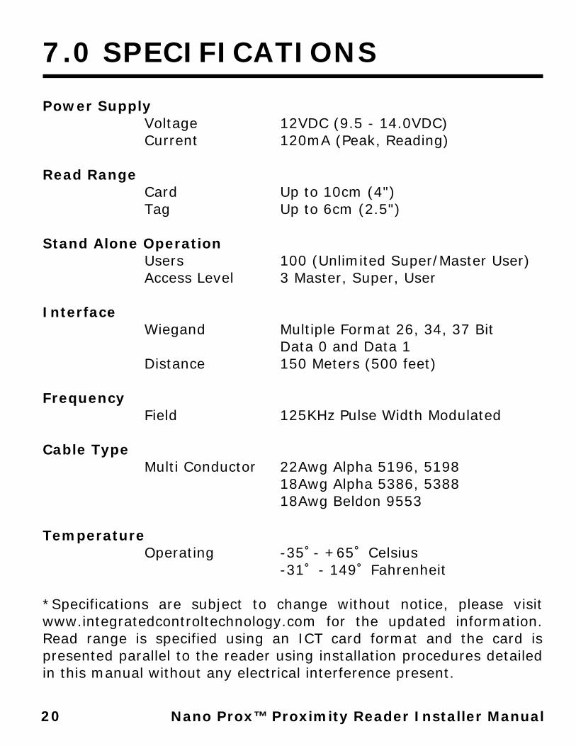
Power Supply Voltage 12VDC (9.5 - 14.0VDC)
Current 120mA (Peak, Reading) Read Range Card Up to 10cm (4") Tag Up to 6cm (2.5") Stand Alone Operation Users 100 (Unlimited Super/Master User) Access Level 3 Master, Super, User Interface Wiegand Multiple Format 26, 34, 37 Bit Data 0 and Data 1
Distance 150 Meters (500 feet) Frequency Field 125KHz Pulse Width Modulated Cable Type Multi Conductor 22Awg Alpha 5196, 5198 18Awg Alpha 5386, 5388 18Awg Beldon 9553 Temperature Operating -35˚- +65˚ Celsius -31˚ - 149˚ Fahrenheit *Specifications are subject to change without notice, please visit www.integratedcontroltechnology.com for the updated information. Read range is specified using an ICT card format and the card is presented parallel to the reader using installation procedures detailed in this manual without any electrical interference present.

21 Nano Prox™ Proximity Reader Installer
8.0 WARRANTY
The Seller warrants its products to be free from defects in materials and workmanship under normal use for a period of one year. Except as specifically stated herein, all express or implied warranties whatsoever, statutory or otherwise, including without limitation, any implied warranty of merchantability and fitness for a particular purpose, are expressly excluded. The Seller does not install or connect the products and because the products may be used in conjunction with products not manufactured by Seller, Seller cannot guarantee the performance of the security system. Seller's obligation and liability under this warranty is expressly limited to repairing or replacing, at Seller's option, any product not meeting the specifications. In no event shall the Seller be liable to the buyer or any other person for any loss or damages whether direct or indirect or consequential or incidental, including without limitation, any damages for lost profits, stolen goods, or claims by any other party caused by defective goods or otherwise arising from the improper, incorrect or otherwise faulty installation or use of the merchandise sold. Protégé® and the logo are registered trademarks of Integrated Control Technology Limited.


NOTES
_______________________________________________________ _______________________________________________________ _______________________________________________________ _______________________________________________________ _______________________________________________________ _______________________________________________________ _______________________________________________________ _______________________________________________________ _______________________________________________________ _______________________________________________________ _______________________________________________________ _______________________________________________________ _______________________________________________________ _______________________________________________________ _______________________________________________________ _______________________________________________________ _______________________________________________________ _______________________________________________________

Unit C, 6 Ascension Place, Mairangi Bay, P.O. Box 302-340 North Harbour, Auckland, New Zealand.
Phone: +64 (9) 476 7124 Fax: +64 (9) 476 7128