provide safe installation for combustion...
TRANSCRIPT

COMBUSTIONEQUIPMENT SAFETY
Provide Safe Installation for Combustion Appliances
OFFICE OF BUILDING TECHNOLOGY, STATE AND COMMUNITY PROGRAMSENERGY EFFICIENCY AND RENEWABLE ENERGY • U.S. DEPARTMENT OF ENERGY
Buildings forthe 21st Century
Buildings that are more
energy efficient, comfortable,
and affordable…that’s the
goal of DOE’s Office of Building
Technology, State and
Community Programs (BTS).
To accelerate the development
and wide application of energy
efficiency measures, BTS:
• Conducts R&D on technologies
and concepts for energy effi-
ciency, working closely with
the building industry and with
manufacturers of materials,
equipment, and appliances
• Promotes energy/money
saving opportunities to both
builders and buyers of homes
and commercial buildings
• Works with state and local
regulatory groups to improve
building codes, appliance stan-
dards, and guidelines for effi-
cient energy use
• Provides support and grants
to states and communities
for deployment of energy-
efficient technologies and
practices
T e c h n o l o g y F a c t S h e e t
E F F I C I E N T C O M B U S T I O NA P P L I A N C E S
Combustion appliances using natural gas,propane, oil, kerosene, or wood are often amore efficient and cost-effective way toproduce heat than electricity.
Examples include
• furnaces• space heaters• fireplaces• wood stoves• water heaters• range tops• ovens• clothes dryers
Combustion applianceshave been used for many years in millions ofhomes. However, careful installation and mainte-nance of each unit is required to ensure safeand efficient operation, especially in today’senergy-efficient, tightly sealed homes.
P R O B L E M S P O S E D B Y C O M B U S T I O NE Q U I P M E N T
Combustion appliances burn fuel by usingoxygen from supply air. They produce exhaustgases that should be directly vented to theoutside to avoid introducing combustionby-products into the house. Exhaust gasesmay be released inside the house eitherknowingly—as in the case of unvented stoves,ovens, fireplaces, or space heaters—orunknowingly from leaky flues, cracked heatexchangers, or backdrafting. Three componentsof exhaust gases are especially troublesomewhen introduced indoors: carbon monoxide,water vapor, and nitrogen oxides.
Carbon monoxide (CO) is a toxic gas that iscolorless, tasteless, and odorless. It can causeserious medical problems and is the cause ofhundreds of deaths in U.S. homes each year.CO is produced when insufficient combustionair is supplied to the appliance, the burner isimproperly tuned, and/or the appliance is mal-functioning.
Water vapor is present in large amounts inexhaust gases as a result of burning all fuels.When water vapor is introduced into a house, itincreases humidity levels and can lead to con-densation on window panes, exterior walls, andinterior surfaces of wall cavities. High humidityand wet surfaces promote mold growth, wooddeterioration, and other health and structuralproblems.
Nitrogen oxides are usually present only insmall amounts in exhaust gases, but they stillpresent a health hazard to the inhabitants.
EFFECTS OF CARBON MONOXIDEEXPOSURECO (ppm) Time Symptoms
35 8 hours Maximum exposureallowed by OSHA in theworkplace over an 8-hourperiod.
200 2-3 hours Mild headache, fatigue,nausea, and dizziness.
400 1-2 hours Serious headache—othersymptoms intensify. Life-threatening after 3 hours.
800 45 minutes Dizziness, nausea, andconvulsions. Unconsciouswithin 2 hours. Deathwithin 2-3 hours.
1600 20 minutes Headache, dizziness, andnausea. Death within1 hour.
For more information, contact:
Energy Efficiency andRenewable EnergyClearinghouse (EREC)1-800-DOE-3732www.eren.doe.gov
Or visit the BTS Web site atwww.eren.doe.gov/buildings
Written and prepared forthe U.S. Department ofEnergy by:
Southface Energy Institute404-872-3549www.southface.org
U.S. Department of Energy’sOak RidgeNational LaboratoryBuildings Technology Center423-574-5178www.ornl.gov/ORNL/BTC
COMBUSTION EQUIPMENT SAFETY
NOTICE: Neither the UnitedStates government nor anyagency thereof, nor any of theiremployees, makes any warranty,express or implied, or assumesany legal liability or responsibilityfor the accuracy, completeness,or usefulness of any information,apparatus, product, or processdisclosed. The views and opin-ions of authors expressed hereindo not necessarily state or reflectthose of the United States gov-ernment or any agency thereof.
Printed with a renewable-source ink on paper containing atleast 50% wastepaper, including 20% postconsumer waste.
October 2000 DOE/GO-102000-0784
C A U S E S O F B A C K D R A F T I N G
Backdrafting occurs when combustion gasesare pulled down the exhaust flue and into thehouse rather than being vented to the outside.Appliances with atmospheric vents rather thanpowered combustion systems are mostsusceptible to backdrafting.
Clothes dryers, ventilation fans in bathroomsand kitchens, and whole-house fans are ex-amples of household equipment that can re-duce the air pressure surrounding the combus-tion appliance to levels that cause it tobackdraft. The potential for backdrafting in-creases the closer the fan is to the appliance,when several fans run simultaneously, andwhen the appliance cannot be isolated from thefan through the use of a closed door or othermeans.
Leaks in heating and cooling ducts or poorlydesigned ductwork can also be a major causeof backdrafting.
Leaks in supply ducts can create a negativepressure in the house (the pressure in thehouse is less than outside) because less airis being returned to the house through thesupply ducts than is being removed fromthe house by the return ducts. If this nega-tive pressure is large enough, it can preventcombustion gases from rising up the flueand cause combustion products to spillinto the house.
A return register that is too close to thecombustion appliance (especially if it is theonly return register in the house) can createa negative pressure around the appliancethat draws exhaust gases into the house. Aleak in a return duct or return plenum thatallows air surrounding the appliances to bedrawn into the return system creates asimilar effect.
TRANSFER GRILLA transfer grill is a small jumper duct often in-
stalled above the door that connects one room to
Foam bafflesdamper sound
Air passes through baffle
Wall cavity
Negative pressures can also be created in themain part of a house, where the combustionappliance often is located, when interiordoors are closed. This can occur especiallywhen there are only one or two return regis-ters in the house and even in homes withtight ductwork. When the doors to roomswith supply registers are closed, it may bedifficult for the air in these rooms to circulateback to a central return register. The pres-sure in the closed-off room increases, andthe pressure decreases in the main part of thehouse open to the central return.
P R E V E N T I N G B A C K D R A F T I N G
The potential for backdrafting can be reduced by
• Using appliances with powered combustionsystems rather than atmospheric vents.
• Installing appliances with atmosphericvents in a sealed combustion closet.
• Sealing all supply and return duct leaks.
• Installing return registers in all rooms withsupply registers.
• Making sure rooms without a return registerhave at least a 1-inch gap under the door(recommended only for rooms with onesupply register) or a transfer grill to providepressure equalization between rooms.
Combustion DOE 784 MS.p65 10/30/00, 12:30 PM1
Fuel-fired furnaces, clothes dryers, and water heaters that arevented to the outside can also pose problems. Their use of in-door air for combustion increases household energy use sincethe air used for combustion must be replaced by outdoor air.
F U R N A C E S A N D W A T E R H E A T E R S
Most new fuel-fired furnaces have a fan-assisted or poweredcombustion system, meaning a small blower forces or drawscombustion air and flue products through the furnace and ex-hausts combustion gases out the flue to the outside. Most fuel-fired water heaters, and some furnaces, still use an atmosphericor natural draft vent—the buoyancy of the hot exhaust gasescarries these combustion products through the appliance and upthe flue. Appliances with atmospheric vents that are installedinside the house are susceptible to backdrafting problems.
Most fuel-fired furnaces and water heaters use air surroundingthe appliance for combustion. Others, known as sealed-combustion or 100-percent-outdoor-air appliances, bring com-bustion air directly into the burner via sealed inlets connectedto the outside and usually have a fan-assisted exhaust. Becausenon-sealed-combustion appliances installed indoors rely onindoor air for combustion, they increase the infiltration rate ofthe house during operation and are more likely to have prob-lems with insufficient combustion air and backdrafting.
Only sealed-combustion furnaces and water heaters that areequipped with a powered combustion system should beinstalled inside a house. Such appliances are provided withsufficient combustion air and are unlikely to backdraft or impactthe infiltration rate of the house. Other types of fuel-firedfurnaces and water heaters should be installed outside theliving area of the house (e.g., in a garage, crawlspace, or attic) orin a sealed combustion closet if an inside location is absolutelyrequired. This action will ensure proper, efficient operation andprevent indoor air quality problems.
U N V E N T E D S P A C E H E A T E R S A N D F I R E P L A C E S
Most energy and health experts advise against unvented spaceheaters or fireplaces. Even when operating properly, these unitsproduce unhealthy exhaust gases such as nitrogen oxides andexcess water vapor. If these units are present, do not weatherizethe home and advise occupants to crack windows open toensure adequate ventilation whenever the units are operating.
S T O V E S A N D O V E N S
Five precautions will help prevent indoor air quality andmoisture problems from fuel-fired stoves and ovens.
• Install a CO detector in the living area near the kitchen.
• Always vent a kitchen exhaust fan to the outside and oper-ate the fan whenever cooking.
• Have the stove or oven, as with all major appliances,serviced regularly (every 2 years is recommended).
• Do not use a range or oven as a space heater.
• Buy a range or oven with pilotless ignition.
I N S T A L L A T I O N
All combustion appliances should be installed by knowledgeabletechnicians according to the manufacturer’s installation instruc-tions as well as following all national and local code requirements.
As part of the installation process, CO measurements should bemade to ensure the proper operation of the units and the safetyand health of the occupants. CO should be measured in the com-bustion products of furnaces and water heaters before thediverter or before dilution occurs, and after the burner has runcontinuously for 5 minutes. Levels greater than 100 ppm (air freerather than as tested) indicate adjustments are necessary; levelsless than 10 ppm usually are readily achievable. Ovens should betested while operating on the BAKE setting, and range topsshould be tested with a water-filled pan over the burner. CO levelsgreater than 50 ppm (air free) are not acceptable.
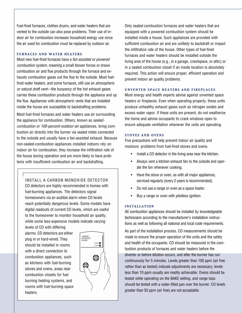
INSTALL A CARBON MONOXIDE DETECTORCO detectors are highly recommended in homes withfuel-burning appliances. The detectors signalhomeowners via an audible alarm when CO levelsreach potentially dangerous levels. Some models havedigital readouts of current CO levels, which are usefulto the homeowner to monitor household air quality,while some less-expensive models indicate varyinglevels of CO with differingalarms. CO detectors are eitherplug in or hard-wired. Theyshould be installed in roomswith a direct connection tocombustion appliances, suchas kitchens with fuel-burningstoves and ovens, areas nearcombustion closets for fuelburning heating systems, androoms with fuel-burning spaceheaters.
COMBUSTION CLOSET REQUIREMENTSA shelf-system combustion closet housing a gas furnace or a com-
bustion closet housing a water heater both require dedicated com-
bustion air sources and a tightly sealed closet environment.
COMBUSTION EQUIPMENT SAFETY
Solid (non-louvered) door with weatherstripping
Door closes against solid threshold
Insulatedwater heater
Bottom platesealed
Insulatedwalls
Seal gas and plumbing penetrations through walls
Vented exhaust pipethrough roof
LowHigh
Screened high and low combustion air ducts into closet (extend 6" above insulation in attic)
SHELF-SYSTEM FURNACE CLOSET
WATER HEATER CLOSET
Return grill with filter
Seal Door closes against solid threshold
Sealed return plenum
Seal penetrations and under bottom plate of walls
Air fromhouse
Weatherstripping
Drywall
Seal around fluewith sheet metal
Supply plenum sealed with mastic and insulated
Insulated wallsbetween equipmentcloset and home
Warning:Do not store anything
in this closet.Keep door shut.
WARNING
Screened high and low combustion air ducts into equipment closet (extend 6 inches above insulation levels in attic)
Solid door (non-louvered) must seal tightly against weatherstripping at top, bottom, and sides
C O M B U S T I O N C L O S E T D E S I G N
Use of sealed-combustion, fan-assisted furnaces and waterheaters is preferred when locating equipment inside the houserather than building a sealed-combustion closet or utility room.A sealed-combustion closet can be difficult to build correctlyand may cost the same as the incremental cost of the sealedand fan-assisted combustion equipment.
A sealed-combustion equipment closet separates the combustionappliance from the living space of the house. Too often, the com-bustion equipment closet is connected to the conditioned space ofthe home by louvered doors, air leaks, and uninsulated walls.
A sealed-combustion closet is like a “little piece of the outsidelocated in the middle of the home.” Fresh air for combustion isprovided from sources not connected with the living space.Isolating the mechanical room from the living area protects thehome against backdrafting and increased heat gains or lossesdue to infiltration or conduction.
A S E A L E D-C O M B U S T I O N C L O S E T I S C O N S T R U C T E D B Y
F O L L O W I N G T H E S E S T E P S :
1. Insulate the four walls of the combustion closet.
2. Finish the walls and ceiling with drywall.
3. Seal all holes and air leakage pathways through the walls,floor, and ceiling that can connect the closet to the rest ofthe house—this includes plumbing, gas lines, wiring, elec-trical boxes, and the bottom plate of the walls.
4. Install a non-louvered door that is weatherstripped andequipped with a properly adjusted threshold.
5. Install two ducts in the closet, extending to the outside orto a ventilated attic or crawlspace, to provide outside airfor combustion. Seal the ducts to the ceiling. Check withlocal codes—the ducts must be sized for the specificcombustion appliances, and usually one duct shouldextend to within 12 inches of the closet floor while theother duct extends to within 12 inches of the ceiling. If theducts are connected to the attic, they should extend6 inches above the insulation level.
6. If a return plenum for a furnace is built below the closet,completely seal the plenum—including the plenum walls,plumbing, and connection of the furnace to the plenum.
7. Seal the ceiling around the flue using sheet metal.
Combustion DOE 784 MS.p65 10/30/00, 12:30 PM2

Fuel-fired furnaces, clothes dryers, and water heaters that arevented to the outside can also pose problems. Their use of in-door air for combustion increases household energy use sincethe air used for combustion must be replaced by outdoor air.
F U R N A C E S A N D W A T E R H E A T E R S
Most new fuel-fired furnaces have a fan-assisted or poweredcombustion system, meaning a small blower forces or drawscombustion air and flue products through the furnace and ex-hausts combustion gases out the flue to the outside. Most fuel-fired water heaters, and some furnaces, still use an atmosphericor natural draft vent—the buoyancy of the hot exhaust gasescarries these combustion products through the appliance and upthe flue. Appliances with atmospheric vents that are installedinside the house are susceptible to backdrafting problems.
Most fuel-fired furnaces and water heaters use air surroundingthe appliance for combustion. Others, known as sealed-combustion or 100-percent-outdoor-air appliances, bring com-bustion air directly into the burner via sealed inlets connectedto the outside and usually have a fan-assisted exhaust. Becausenon-sealed-combustion appliances installed indoors rely onindoor air for combustion, they increase the infiltration rate ofthe house during operation and are more likely to have prob-lems with insufficient combustion air and backdrafting.
Only sealed-combustion furnaces and water heaters that areequipped with a powered combustion system should beinstalled inside a house. Such appliances are provided withsufficient combustion air and are unlikely to backdraft or impactthe infiltration rate of the house. Other types of fuel-firedfurnaces and water heaters should be installed outside theliving area of the house (e.g., in a garage, crawlspace, or attic) orin a sealed combustion closet if an inside location is absolutelyrequired. This action will ensure proper, efficient operation andprevent indoor air quality problems.
U N V E N T E D S P A C E H E A T E R S A N D F I R E P L A C E S
Most energy and health experts advise against unvented spaceheaters or fireplaces. Even when operating properly, these unitsproduce unhealthy exhaust gases such as nitrogen oxides andexcess water vapor. If these units are present, do not weatherizethe home and advise occupants to crack windows open toensure adequate ventilation whenever the units are operating.
S T O V E S A N D O V E N S
Five precautions will help prevent indoor air quality andmoisture problems from fuel-fired stoves and ovens.
• Install a CO detector in the living area near the kitchen.
• Always vent a kitchen exhaust fan to the outside and oper-ate the fan whenever cooking.
• Have the stove or oven, as with all major appliances,serviced regularly (every 2 years is recommended).
• Do not use a range or oven as a space heater.
• Buy a range or oven with pilotless ignition.
I N S T A L L A T I O N
All combustion appliances should be installed by knowledgeabletechnicians according to the manufacturer’s installation instruc-tions as well as following all national and local code requirements.
As part of the installation process, CO measurements should bemade to ensure the proper operation of the units and the safetyand health of the occupants. CO should be measured in the com-bustion products of furnaces and water heaters before thediverter or before dilution occurs, and after the burner has runcontinuously for 5 minutes. Levels greater than 100 ppm (air freerather than as tested) indicate adjustments are necessary; levelsless than 10 ppm usually are readily achievable. Ovens should betested while operating on the BAKE setting, and range topsshould be tested with a water-filled pan over the burner. CO levelsgreater than 50 ppm (air free) are not acceptable.
INSTALL A CARBON MONOXIDE DETECTORCO detectors are highly recommended in homes withfuel-burning appliances. The detectors signalhomeowners via an audible alarm when CO levelsreach potentially dangerous levels. Some models havedigital readouts of current CO levels, which are usefulto the homeowner to monitor household air quality,while some less-expensive models indicate varyinglevels of CO with differingalarms. CO detectors are eitherplug in or hard-wired. Theyshould be installed in roomswith a direct connection tocombustion appliances, suchas kitchens with fuel-burningstoves and ovens, areas nearcombustion closets for fuelburning heating systems, androoms with fuel-burning spaceheaters.
COMBUSTION CLOSET REQUIREMENTSA shelf-system combustion closet housing a gas furnace or a com-
bustion closet housing a water heater both require dedicated com-
bustion air sources and a tightly sealed closet environment.
COMBUSTION EQUIPMENT SAFETY
Solid (non-louvered) door with weatherstripping
Door closes against solid threshold
Insulatedwater heater
Bottom platesealed
Insulatedwalls
Seal gas and plumbing penetrations through walls
Vented exhaust pipethrough roof
LowHigh
Screened high and low combustion air ducts into closet (extend 6" above insulation in attic)
SHELF-SYSTEM FURNACE CLOSET
WATER HEATER CLOSET
Return grill with filter
Seal Door closes against solid threshold
Sealed return plenum
Seal penetrations and under bottom plate of walls
Air fromhouse
Weatherstripping
Drywall
Seal around fluewith sheet metal
Supply plenum sealed with mastic and insulated
Insulated wallsbetween equipmentcloset and home
Warning:Do not store anything
in this closet.Keep door shut.
WARNING
Screened high and low combustion air ducts into equipment closet (extend 6 inches above insulation levels in attic)
Solid door (non-louvered) must seal tightly against weatherstripping at top, bottom, and sides
C O M B U S T I O N C L O S E T D E S I G N
Use of sealed-combustion, fan-assisted furnaces and waterheaters is preferred when locating equipment inside the houserather than building a sealed-combustion closet or utility room.A sealed-combustion closet can be difficult to build correctlyand may cost the same as the incremental cost of the sealedand fan-assisted combustion equipment.
A sealed-combustion equipment closet separates the combustionappliance from the living space of the house. Too often, the com-bustion equipment closet is connected to the conditioned space ofthe home by louvered doors, air leaks, and uninsulated walls.
A sealed-combustion closet is like a “little piece of the outsidelocated in the middle of the home.” Fresh air for combustion isprovided from sources not connected with the living space.Isolating the mechanical room from the living area protects thehome against backdrafting and increased heat gains or lossesdue to infiltration or conduction.
A S E A L E D-C O M B U S T I O N C L O S E T I S C O N S T R U C T E D B Y
F O L L O W I N G T H E S E S T E P S :
1. Insulate the four walls of the combustion closet.
2. Finish the walls and ceiling with drywall.
3. Seal all holes and air leakage pathways through the walls,floor, and ceiling that can connect the closet to the rest ofthe house—this includes plumbing, gas lines, wiring, elec-trical boxes, and the bottom plate of the walls.
4. Install a non-louvered door that is weatherstripped andequipped with a properly adjusted threshold.
5. Install two ducts in the closet, extending to the outside orto a ventilated attic or crawlspace, to provide outside airfor combustion. Seal the ducts to the ceiling. Check withlocal codes—the ducts must be sized for the specificcombustion appliances, and usually one duct shouldextend to within 12 inches of the closet floor while theother duct extends to within 12 inches of the ceiling. If theducts are connected to the attic, they should extend6 inches above the insulation level.
6. If a return plenum for a furnace is built below the closet,completely seal the plenum—including the plenum walls,plumbing, and connection of the furnace to the plenum.
7. Seal the ceiling around the flue using sheet metal.
Combustion DOE 784 MS.p65 10/30/00, 12:30 PM2

COMBUSTIONEQUIPMENT SAFETY
Provide Safe Installation for Combustion Appliances
OFFICE OF BUILDING TECHNOLOGY, STATE AND COMMUNITY PROGRAMSENERGY EFFICIENCY AND RENEWABLE ENERGY • U.S. DEPARTMENT OF ENERGY
Buildings forthe 21st Century
Buildings that are more
energy efficient, comfortable,
and affordable…that’s the
goal of DOE’s Office of Building
Technology, State and
Community Programs (BTS).
To accelerate the development
and wide application of energy
efficiency measures, BTS:
• Conducts R&D on technologies
and concepts for energy effi-
ciency, working closely with
the building industry and with
manufacturers of materials,
equipment, and appliances
• Promotes energy/money
saving opportunities to both
builders and buyers of homes
and commercial buildings
• Works with state and local
regulatory groups to improve
building codes, appliance stan-
dards, and guidelines for effi-
cient energy use
• Provides support and grants
to states and communities
for deployment of energy-
efficient technologies and
practices
T e c h n o l o g y F a c t S h e e t
E F F I C I E N T C O M B U S T I O NA P P L I A N C E S
Combustion appliances using natural gas,propane, oil, kerosene, or wood are often amore efficient and cost-effective way toproduce heat than electricity.
Examples include
• furnaces• space heaters• fireplaces• wood stoves• water heaters• range tops• ovens• clothes dryers
Combustion applianceshave been used for many years in millions ofhomes. However, careful installation and mainte-nance of each unit is required to ensure safeand efficient operation, especially in today’senergy-efficient, tightly sealed homes.
P R O B L E M S P O S E D B Y C O M B U S T I O NE Q U I P M E N T
Combustion appliances burn fuel by usingoxygen from supply air. They produce exhaustgases that should be directly vented to theoutside to avoid introducing combustionby-products into the house. Exhaust gasesmay be released inside the house eitherknowingly—as in the case of unvented stoves,ovens, fireplaces, or space heaters—orunknowingly from leaky flues, cracked heatexchangers, or backdrafting. Three componentsof exhaust gases are especially troublesomewhen introduced indoors: carbon monoxide,water vapor, and nitrogen oxides.
Carbon monoxide (CO) is a toxic gas that iscolorless, tasteless, and odorless. It can causeserious medical problems and is the cause ofhundreds of deaths in U.S. homes each year.CO is produced when insufficient combustionair is supplied to the appliance, the burner isimproperly tuned, and/or the appliance is mal-functioning.
Water vapor is present in large amounts inexhaust gases as a result of burning all fuels.When water vapor is introduced into a house, itincreases humidity levels and can lead to con-densation on window panes, exterior walls, andinterior surfaces of wall cavities. High humidityand wet surfaces promote mold growth, wooddeterioration, and other health and structuralproblems.
Nitrogen oxides are usually present only insmall amounts in exhaust gases, but they stillpresent a health hazard to the inhabitants.
EFFECTS OF CARBON MONOXIDEEXPOSURECO (ppm) Time Symptoms
35 8 hours Maximum exposureallowed by OSHA in theworkplace over an 8-hourperiod.
200 2-3 hours Mild headache, fatigue,nausea, and dizziness.
400 1-2 hours Serious headache—othersymptoms intensify. Life-threatening after 3 hours.
800 45 minutes Dizziness, nausea, andconvulsions. Unconsciouswithin 2 hours. Deathwithin 2-3 hours.
1600 20 minutes Headache, dizziness, andnausea. Death within1 hour.
For more information, contact:
Energy Efficiency andRenewable EnergyClearinghouse (EREC)1-800-DOE-3732www.eren.doe.gov
Or visit the BTS Web site atwww.eren.doe.gov/buildings
Written and prepared forthe U.S. Department ofEnergy by:
Southface Energy Institute404-872-3549www.southface.org
U.S. Department of Energy’sOak RidgeNational LaboratoryBuildings Technology Center423-574-5178www.ornl.gov/ORNL/BTC
COMBUSTION EQUIPMENT SAFETY
NOTICE: Neither the UnitedStates government nor anyagency thereof, nor any of theiremployees, makes any warranty,express or implied, or assumesany legal liability or responsibilityfor the accuracy, completeness,or usefulness of any information,apparatus, product, or processdisclosed. The views and opin-ions of authors expressed hereindo not necessarily state or reflectthose of the United States gov-ernment or any agency thereof.
Printed with a renewable-source ink on paper containing atleast 50% wastepaper, including 20% postconsumer waste.
October 2000 DOE/GO-102000-0784
C A U S E S O F B A C K D R A F T I N G
Backdrafting occurs when combustion gasesare pulled down the exhaust flue and into thehouse rather than being vented to the outside.Appliances with atmospheric vents rather thanpowered combustion systems are mostsusceptible to backdrafting.
Clothes dryers, ventilation fans in bathroomsand kitchens, and whole-house fans are ex-amples of household equipment that can re-duce the air pressure surrounding the combus-tion appliance to levels that cause it tobackdraft. The potential for backdrafting in-creases the closer the fan is to the appliance,when several fans run simultaneously, andwhen the appliance cannot be isolated from thefan through the use of a closed door or othermeans.
Leaks in heating and cooling ducts or poorlydesigned ductwork can also be a major causeof backdrafting.
Leaks in supply ducts can create a negativepressure in the house (the pressure in thehouse is less than outside) because less airis being returned to the house through thesupply ducts than is being removed fromthe house by the return ducts. If this nega-tive pressure is large enough, it can preventcombustion gases from rising up the flueand cause combustion products to spillinto the house.
A return register that is too close to thecombustion appliance (especially if it is theonly return register in the house) can createa negative pressure around the appliancethat draws exhaust gases into the house. Aleak in a return duct or return plenum thatallows air surrounding the appliances to bedrawn into the return system creates asimilar effect.
TRANSFER GRILLA transfer grill is a small jumper duct often in-
stalled above the door that connects one room to
Foam bafflesdamper sound
Air passes through baffle
Wall cavity
Negative pressures can also be created in themain part of a house, where the combustionappliance often is located, when interiordoors are closed. This can occur especiallywhen there are only one or two return regis-ters in the house and even in homes withtight ductwork. When the doors to roomswith supply registers are closed, it may bedifficult for the air in these rooms to circulateback to a central return register. The pres-sure in the closed-off room increases, andthe pressure decreases in the main part of thehouse open to the central return.
P R E V E N T I N G B A C K D R A F T I N G
The potential for backdrafting can be reduced by
• Using appliances with powered combustionsystems rather than atmospheric vents.
• Installing appliances with atmosphericvents in a sealed combustion closet.
• Sealing all supply and return duct leaks.
• Installing return registers in all rooms withsupply registers.
• Making sure rooms without a return registerhave at least a 1-inch gap under the door(recommended only for rooms with onesupply register) or a transfer grill to providepressure equalization between rooms.
Combustion DOE 784 MS.p65 10/30/00, 12:30 PM1