proton plan
DESCRIPTION
Proton Plan. Eric Prebys FNAL Accelerator Division. “Proton Plan”. The details of proton demand and issues can be found in an official report to the director at: www.fnal.gov/directorate/program_planning/studies/ProtonReport.pdf Working assumptions: - PowerPoint PPT PresentationTRANSCRIPT
Proton PlanProton Plan
Eric PrebysFNAL Accelerator Division
Proton Plan, September 21st, 2004 - Prebys 2
““Proton Plan”Proton Plan” The details of proton demand and issues can be found in
an official report to the director at: www.fnal.gov/directorate/program_planning/studies/ProtonReport.pdf
Working assumptions: Existing proton source must last at least another 10 years or
so in more or less it’s current configuration. During that time, a new “proton driver” will be built, which
will ultimately replace the existing proton source. Proton source improvements should require no significant
downtimes beyond those needed for other reasons. The maximum total funding for proton source improvements
will be of the order of $18M over the next few years. Near term projects most important to performance
Proton Plan, September 21st, 2004 - Prebys 3
Scope of ImprovementsScope of Improvements The level of funding precludes some things
which have been discussed: Replacement or major upgrade of 200 MHz linac
• Official policy on 7835 PA’s: keep fingers crossed. Decrease of Main Injector ramp time
• Unless it is done as part of Proton Driver For this reason, the proton plan focuses
primarily on the Booster Decreasing uncontrolled losses. Increasing reliable average repetition rate. Biggest decisions involve plan for RF system.
Proton Plan, September 21st, 2004 - Prebys 4
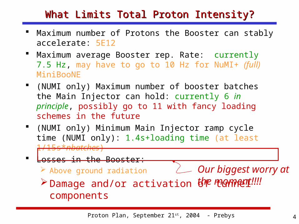
What Limits Total Proton Intensity?What Limits Total Proton Intensity? Maximum number of Protons the Booster can stably
accelerate: 5E12 Maximum average Booster rep. Rate: currently 7.5 Hz,
may have to go to 10 Hz for NuMI+ (full) MiniBooNE (NUMI only) Maximum number of booster batches the
Main Injector can hold: currently 6 in principle, possibly go to 11 with fancy loading schemes in the future
(NUMI only) Minimum Main Injector ramp cycle time (NUMI only): 1.4s+loading time (at least 1/15s*nbatches)
Losses in the Booster: Above ground radiationDamage and/or activation of tunnel
components Our biggest worry at the moment!!!!
Proton Plan, September 21st, 2004 - Prebys 5
Early EffortsEarly Efforts Shielding and reclassifying Booster towers. More sophisticated loss monitoring methods. Extraction notch:
Kick notch in beam early in cycle to reduce loss at extraction.
Install ramped corrector system. Used to reduce losses at specific locations. Ultimately limited by corrector strength.
Replace Long 3 extraction septum and power supply: Increase maximum average rep. rate.
Increase efforts to understand the physics of the Booster.
Proton Plan, September 21st, 2004 - Prebys 6
Booster Modeling EffortsBooster Modeling Efforts At the beginning of 2001:
The transverse lattice model for the Booster was the ideal lattice of TM-405:
• No correctors• No injection or extraction elements• No higher order moments• Etc.
There was no realistic longitudinal model. It was believed that space charge at injection was a
significant problem. A group formed to study… Now:
Transverse model includes• All correctors• All injection and extraction elements• Body multipoles• Alignment data
Detailed longitudinal model, verified by measurement. Believable space charge simulations, verified by
measurements.
Proton Plan, September 21st, 2004 - Prebys 7
Results of Modeling EffortsResults of Modeling Efforts Space charge effects, while present, do not
appear to be a huge effect. Larger Issues:
Dogleg effect.• Distortion at injection cause by extraction doglegs.• Major discovery. Became focus of our efforts.
Beam motion:• Misalignment• Limited correctors• Horizontal slewing due to underpowered injection bump
magnets (ORBUMP). RF Power limitations:
• Existing RF marginal to get beam through transition.
Proton Plan, September 21st, 2004 - Prebys 8
Big Improvements in the Last YearBig Improvements in the Last Year Primary extraction “dogleg fix”
Increase spacing between magnets in chicane system
Reduces distortion to injection lattice by ~40% Vertical alignment
Eliminate ¼” misalignment at collimator region Improve high field orbit
400 MeV line work Better understanding Improved stability and repeatability
Injection bump (ORBUMP) improvements Improved water flow New, lower resistance capacitors Much more reliable
Collimator installation and commissioning
Proton Plan, September 21st, 2004 - Prebys 9
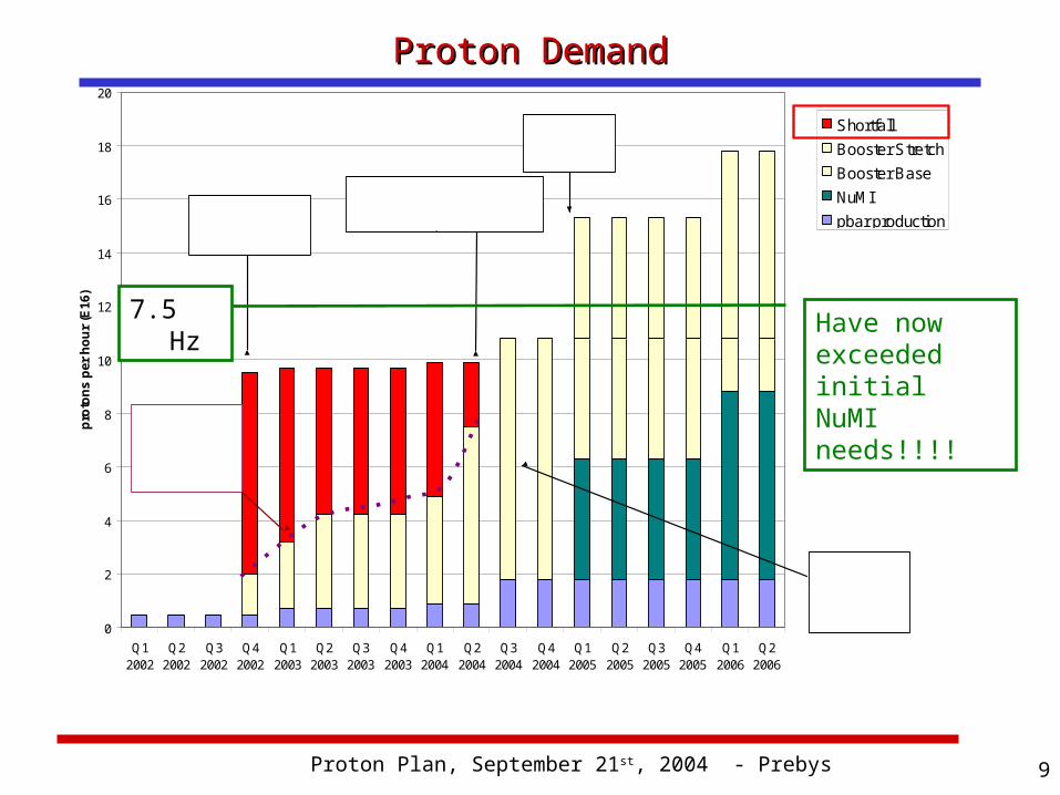
Proton DemandProton Demand
0
2
4
6
8
10
12
14
16
18
20
Q12002
Q22002
Q32002
Q42002
Q12003
Q22003
Q32003
Q42003
Q12004
Q22004
Q32004
Q42004
Q12005
Q22005
Q32005
Q42005
Q12006
Q22006
prot
ons
per h
our (
E16)
ShortfallBooster StretchBooster BaseNuMIpbar production
Booster Maximum ( loss limit)
MiniBooNE Turn-on
NuMITurn-on
Now(Note I mprovement!)
This is a goal, not a promise!!!
Have now exceeded initial NuMI needs!!!!
7.5 Hz
Proton Plan, September 21st, 2004 - Prebys 10
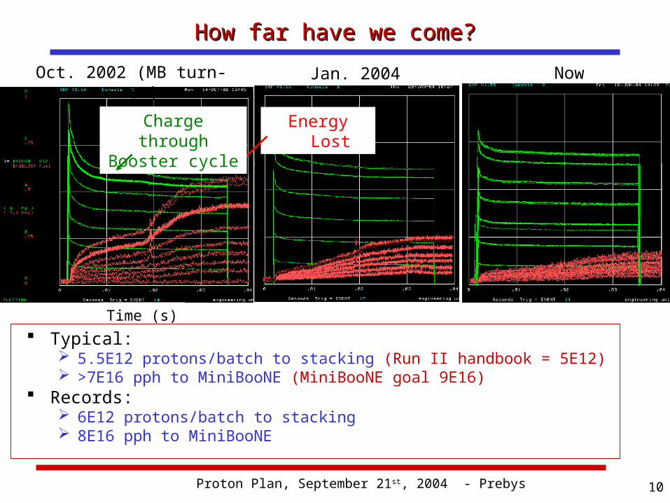
How far have we come?How far have we come?
Typical: 5.5E12 protons/batch to stacking (Run II handbook = 5E12) >7E16 pph to MiniBooNE (MiniBooNE goal 9E16)
Records: 6E12 protons/batch to stacking 8E16 pph to MiniBooNE
Time (s)
Oct. 2002 (MB turn-on) Jan. 2004
Energy LostCharge through Booster cycle
Now
Proton Plan, September 21st, 2004 - Prebys 11
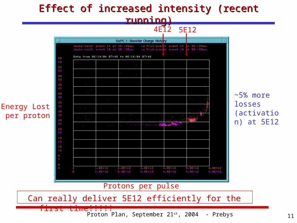
Effect of increased intensity (recent running)Effect of increased intensity (recent running)
Energy Lost per proton
Protons per pulse
4E12 5E12
~5% more losses (activation) at 5E12
Can really deliver 5E12 efficiently for the first time!!!!!
Proton Plan, September 21st, 2004 - Prebys 12
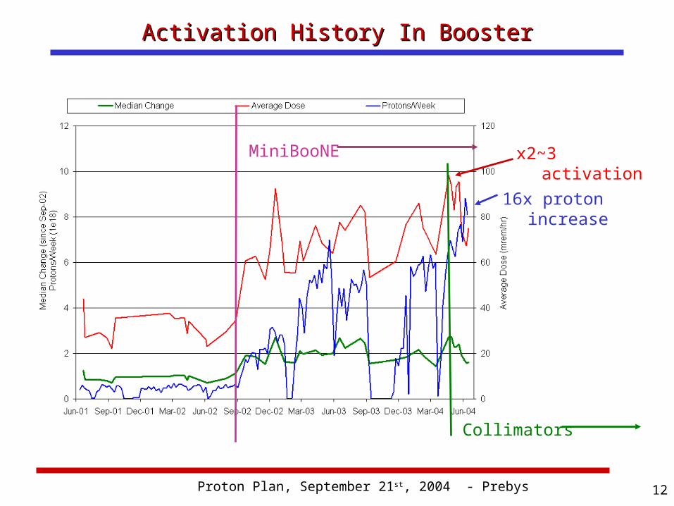
Activation History In BoosterActivation History In Booster
MiniBooNE
16x proton increase
x2~3 activation
Collimators
Proton Plan, September 21st, 2004 - Prebys 13
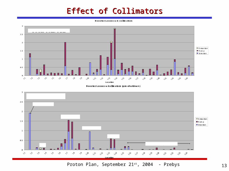
Effect of CollimatorsEffect of Collimators
Booster Losses w/collimators (pre-shutdown)
0
0.5
1
1.5
2
2.5
3
Location
Extraction
Ramp
Injection
Collimators
Notch Loss
L13
L3 RF Region
Prompt Loss
After Collimators
Booster Losses w/o collimators
0
0.5
1
1.5
2
2.5
3
Location
Extraction
Ramp
Injection
Before Collimators
e
Proton Plan, September 21st, 2004 - Prebys 14
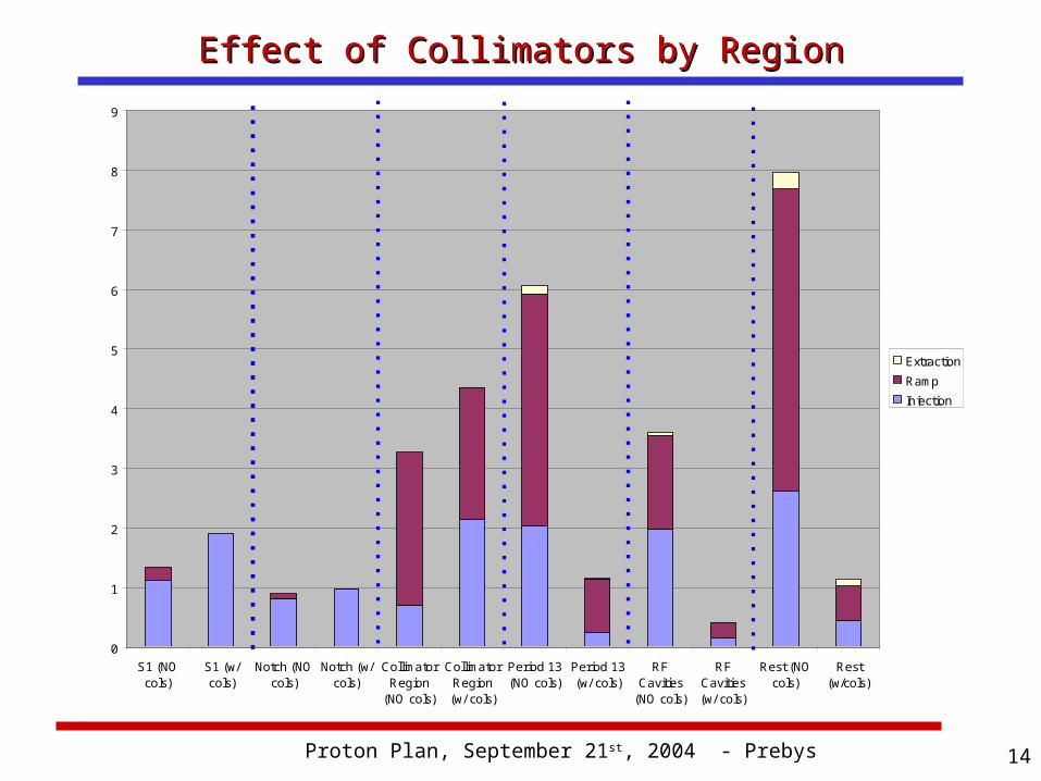
Effect of Collimators by RegionEffect of Collimators by Region
0
1
2
3
4
5
6
7
8
9
S1 (NOcols)
S1 (w/cols)
Notch (NOcols)
Notch (w/cols)
CollimatorRegion
(NO cols)
CollimatorRegion(w/ cols)
Period 13(NO cols)
Period 13(w/ cols)
RFCavities
(NO cols)
RFCavities(w/ cols)
Rest (NOcols)
Rest(w/cols)
ExtractionRampInjection
Proton Plan, September 21st, 2004 - Prebys 15
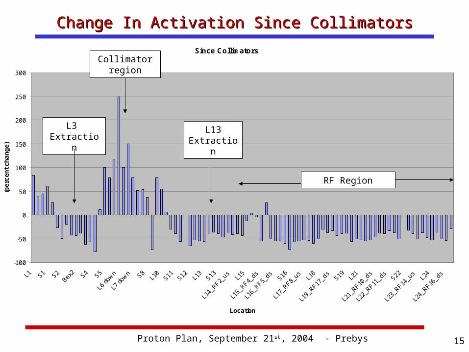
Change In Activation Since CollimatorsChange In Activation Since CollimatorsSince Collimators
-100
-50
0
50
100
150
200
250
300
L1 S1 S2Bex
2 S4 S5
L6 do
wn
L7 do
wn S8L1
0S11
S12 L13
S13
L14_R
F2_us L1
5
L15_R
F4_ds
L16_R
F5_ds S16
L17_R
F8_us L1
8
L19_R
F17_d
sS19 L2
1
L21_R
F10_d
s
L22_
RF11_d
sS22
L23_R
F14_u
sL2
4
L24_R
F16_d
s
Location
(per
cent
cha
nge)
Collimatorregion
RF Region
L13Extraction
L3 Extraction
Proton Plan, September 21st, 2004 - Prebys 16
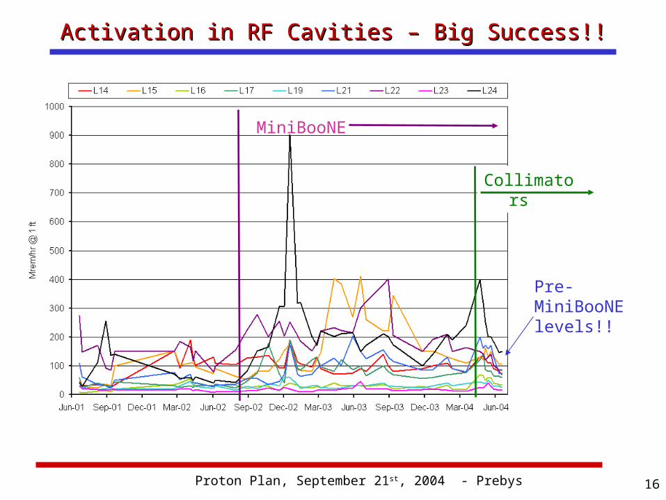
Activation in RF Cavities – Big Success!!Activation in RF Cavities – Big Success!!
MiniBooNE
Collimators
Pre-MiniBooNE levels!!
Proton Plan, September 21st, 2004 - Prebys 17
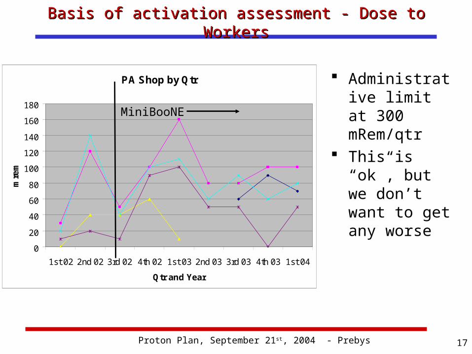
Basis of activation assessment - Dose to WorkersBasis of activation assessment - Dose to Workers
Administrative limit at 300 mRem/qtr
This is “ok”, but we don’t want to get any worse
PA Shop by Qtr
0
20
40
60
80
100
120
140
160
180
1st 02 2nd 02 3rd 02 4th 02 1st 03 2nd 03 3rd 03 4th 03 1st 04
Qtr and Year
mre
m
MiniBooNE
Proton Plan, September 21st, 2004 - Prebys 18
Status before shutdownStatus before shutdown Exceeding Run II intensity goals Can deliver 5E12 protons per batch with good
efficiency Regularly delivering ~80% of MiniBooNE goal Demonstrated NuMI intensities. Headroom left for at least some 8 GeV line
operation.
Proton Plan, September 21st, 2004 - Prebys 19
Major Performance-related Shutdown ProjectsMajor Performance-related Shutdown Projects Modify L13 extraction region:
Overall ~5 reduction in original “dogleg effect” Factor of 3 reduction over present effect
Adding 19th RF cavity: Use large aperture prototype Increase maximum batch size (~6.5E12) Increase reliability (can run with one failure)
Prep. for 20th cavity next year Complete modern laser tracker 3D network
and as-found in the Booster and 400 MeV line: Will be used to fully align the Booster next year
Move “pinger” girder to period 5: Extraction pre-notch will now fire into collimators Phased to aid extraction at both extraction regions!
Proton Plan, September 21st, 2004 - Prebys 20
Issues for the Longer TermIssues for the Longer Term Linac
Quad supplies very old, reliability concern. Unstable filament current has been a recurring
problem. In general, instrumentation is inadequate,
particularly in the Low Energy Linac (LEL). LEL LLRF in need of an upgrade. Nothing planned which will dramatically increase
peak performance.
Proton Plan, September 21st, 2004 - Prebys 21
Issues (cont’d)Issues (cont’d) Booster
Injection bump system (ORBUMP) must be replaced (discussed shortly).
• Will affect both rep. rate and performance Alignment RF
• Reliabilty• Power
Instrumentation• Existing system limited, inconsistent, and not
compatible with 15 Hz operation
Proton Plan, September 21st, 2004 - Prebys 22
Issues (cont’d)Issues (cont’d) Main Injector
Aperture RF
• Existing RF not powerful enough for potential protons from Booster
Proton Plan, September 21st, 2004 - Prebys 23
ORBUMP ReplacementORBUMP Replacement The existing injection bump (ORBUMP) system has
several major problems: Magnet and power supply heating limit the average rep.
rate to ~7.5 Hz. The system is not powerful enough to bump the beam the
required amount, resulting in close to a centimeter of horizontal beam slewing at injection!
Power supply switch network based on a large number (48) of obsolete SCR’s. Maintenance an issue.
Working on a new magnet and power supply: Magnets based on ferrite. Heating not an issue. New power supply.
• Higher rate capacitors• Modern SCR network• Modern charging controller
Entire system good for full 15 Hz Powerful enough to eliminate injection slewing.
Hope to be ready to install early to mid 2005.
Proton Plan, September 21st, 2004 - Prebys 24
Booster AlignmentBooster Alignment It has long been realized that there are
significant alignment problems in the Booster. These cause losses both through aperture
reduction and beam motion. Last year’s vertical as-found uncovered
significant problems, which were addressed. Over the shutdown, we are in the process of a
full laser-tracker 3D network and as-found of the Booster.
We will use that information over the next year to come up with an optimum set of horizontal moves.
Proton Plan, September 21st, 2004 - Prebys 25
Booster RF Cavity Options ConsideredBooster RF Cavity Options Considered Move forward with 5” prototype design?
Design complete and tested Could begin procurement and construction
immediately in FY05. Aggressive schedule could have cavities in place by
2007 Cost: ~6M
Completely new design? Could be designed with higher GE voltage and
reduced HOM. Frequency range a challenge Could have design by end of 2005, cavities in place
by 2008 Control losses with alignment and collimators?
Based on our successes to date, it appears we can Don’t replaceThis is my preliminary
recommendation
Proton Plan, September 21st, 2004 - Prebys 26
Solid State RF driversSolid State RF drivers Existing system is by far our biggest
maintenance item. Usually the older PA’s Average 1½ per month out of 17 cavities -> MTBF of
1 year. >$400K just for replacement cascode tubes. The technicians who service these tubes receive
some of the highest average radiation doses at the lab.
Newer solid state tubes much more reliable MTBF of at least 3 years. More or less identical to MI Prototype running in Booster for three years. Upgrade can be combined with necessary Main
Injector Upgrade.
Proton Plan, September 21st, 2004 - Prebys 27
Corrector PackagesCorrector Packages The Booster contains corrector packages at
each of the 48 sub-periods. Horizontal trim Vertical trim Quad Skew quad
The trims are not powerful enough to control the orbit throughout the cycle
The quads are not powerful enough to fully control the tune/coupling throughout the cycle
Proton Plan, September 21st, 2004 - Prebys 28
Corrector Package Specifications – Position Corrector Package Specifications – Position ControlControl
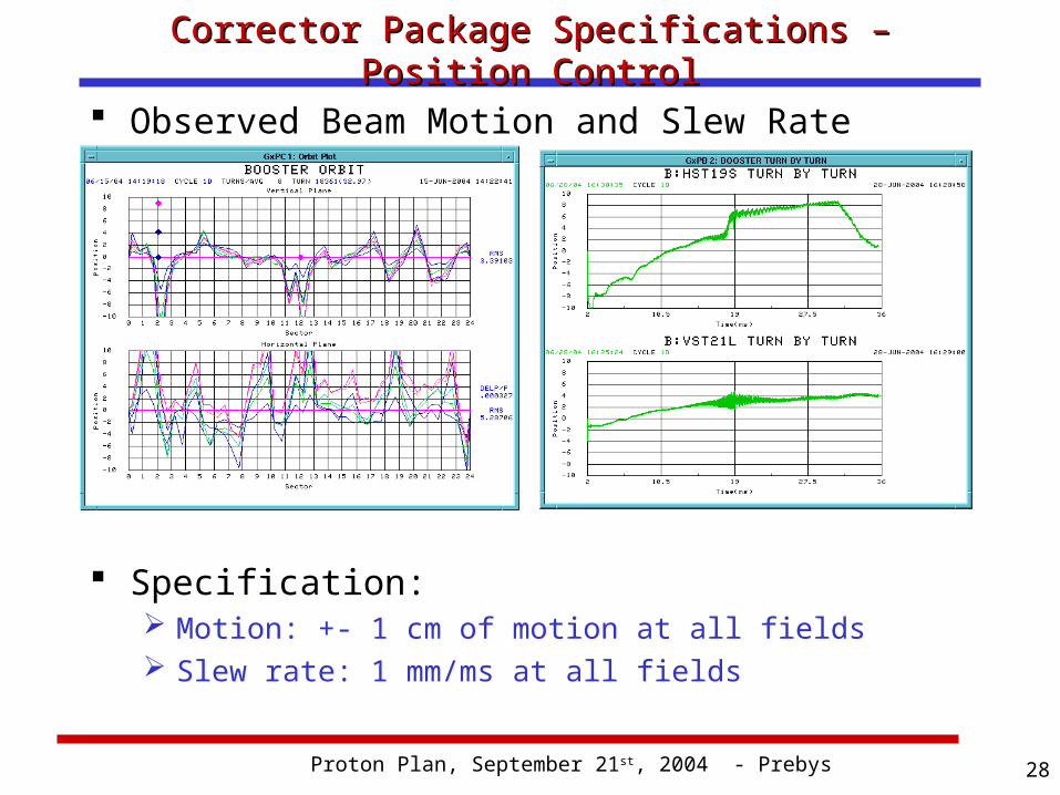
Observed Beam Motion and Slew Rate
Specification: Motion: +- 1 cm of motion at all fields Slew rate: 1 mm/ms at all fields
Proton Plan, September 21st, 2004 - Prebys 29
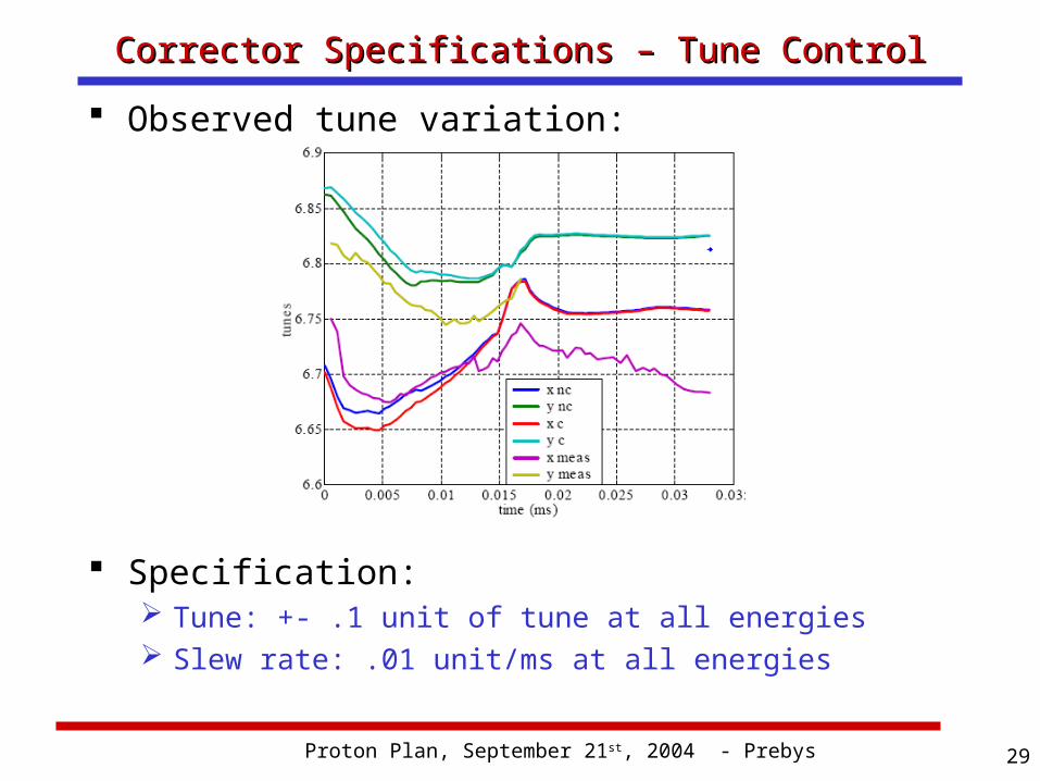
Corrector Specifications – Tune ControlCorrector Specifications – Tune Control Observed tune variation:
Specification: Tune: +- .1 unit of tune at all energies Slew rate: .01 unit/ms at all energies
Proton Plan, September 21st, 2004 - Prebys 30
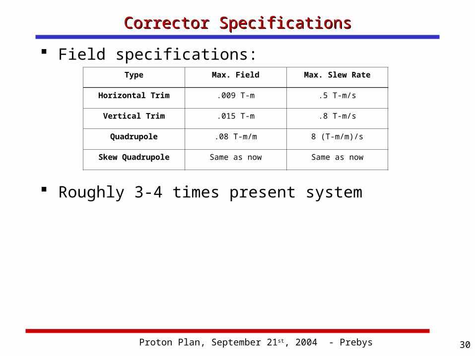
Corrector SpecificationsCorrector Specifications Field specifications:
Roughly 3-4 times present system
Type Max. Field Max. Slew Rate
Horizontal Trim .009 T-m .5 T-m/s
Vertical Trim .015 T-m .8 T-m/s
Quadrupole .08 T-m/m 8 (T-m/m)/s
Skew Quadrupole Same as now Same as now
Proton Plan, September 21st, 2004 - Prebys 31
Booster InstrumentationBooster Instrumentation The existing Booster instrumentation is a mish-mash of
different technologies Most devices are read out through MADC channels
• Limited by C190 multiplexing• Not capable of reliable 15 Hz operation.
The BPM’s are read out through a dedicated digitization system;
• Capable of turn-by-turn readout of the entire system, BUT• Very slow to read out entire system.• Non-standard data interface complicates analysis.• Existing digitizers no longer available.
BLM system read out by IRM system:• Good to full 15 Hz.• No channel limit.• Is there something better now?
Plan Work with instrumentation this year to determine the best
solution for Booster readout, capable of snapshotting the entire Booster on and event-by-event basis.
Proton Plan, September 21st, 2004 - Prebys 32
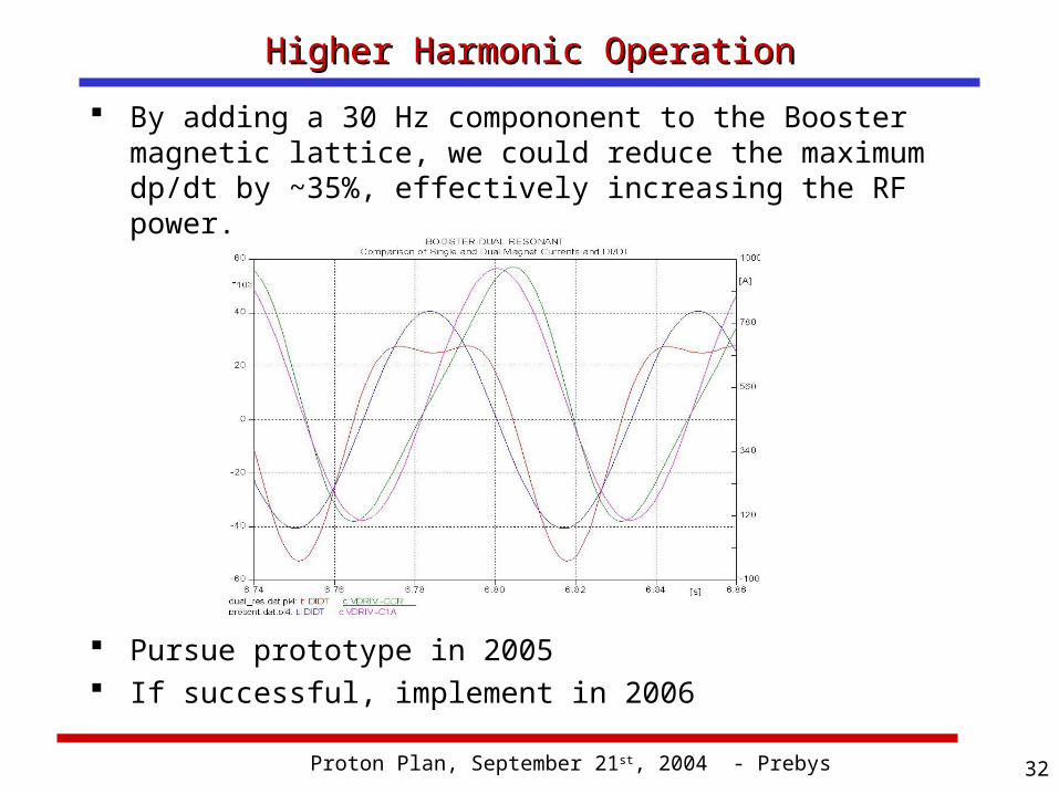
Higher Harmonic OperationHigher Harmonic Operation By adding a 30 Hz compononent to the Booster
magnetic lattice, we could reduce the maximum dp/dt by ~35%, effectively increasing the RF power.
Pursue prototype in 2005 If successful, implement in 2006
Proton Plan, September 21st, 2004 - Prebys 33
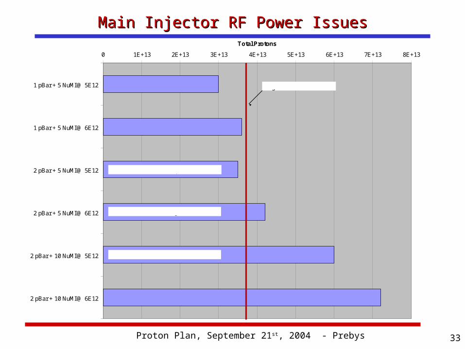
Main Injector RF Power IssuesMain Injector RF Power Issues0 1E+13 2E+13 3E+13 4E+13 5E+13 6E+13 7E+13 8E+13
1 pBar + 5 NuMI @ 5E12
1 pBar + 5 NuMI @ 6E12
2 pBar + 5 NuMI @ 5E12
2 pBar + 5 NuMI @ 6E12
2 pBar + 10 NuMI @ 5E12
2 pBar + 10 NuMI @ 6E12
Total Protons
Baseline 2005 Operation
Single PA RF Power Limit
Possible during 2005
Goal for 2006
Proton Plan, September 21st, 2004 - Prebys 34
Booster/MI RF Upgrade ProjectBooster/MI RF Upgrade Project Goals:
Replace Booster PA’s with solid state versions, of the type used in the Main Injector.
Add a second PA to each Main Injector cavity. Plan:
Construct new PA’s and solid state drivers• 20 for Booster• 20 for second MI port.
Build new modulators for MI dual PA cavities: Move old MI modulators to Booster.
Proton Plan, September 21st, 2004 - Prebys 35
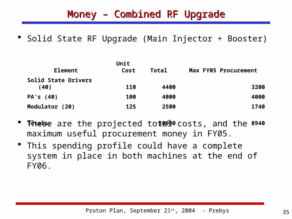
Money – Combined RF UpgradeMoney – Combined RF Upgrade
Element Unit Cost Total Max FY05 ProcurementSolid State Drivers (40) 110 4400 3200PA's (40) 100 4000 4000Modulator (20) 125 2500 1740
Totals: 10900 8940
Solid State RF Upgrade (Main Injector + Booster)
These are the projected total costs, and the maximum useful procurement money in FY05.
This spending profile could have a complete system in place in both machines at the end of FY06.
Proton Plan, September 21st, 2004 - Prebys 36
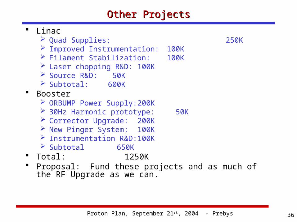
Other ProjectsOther Projects Linac
Quad Supplies: 250K Improved Instrumentation: 100K Filament Stabilization: 100K Laser chopping R&D: 100K Source R&D: 50K Subtotal: 600K
Booster ORBUMP Power Supply: 200K 30Hz Harmonic prototype: 50K Corrector Upgrade: 200K New Pinger System: 100K Instrumentation R&D: 100K Subtotal 650K
Total: 1250K Proposal: Fund these projects and as much of the RF
Upgrade as we can.
Proton Plan, September 21st, 2004 - Prebys 37
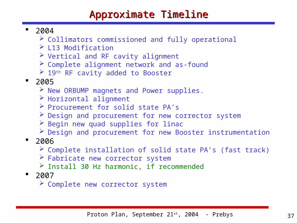
Approximate TimelineApproximate Timeline 2004
Collimators commissioned and fully operational L13 Modification Vertical and RF cavity alignment Complete alignment network and as-found 19th RF cavity added to Booster
2005 New ORBUMP magnets and Power supplies. Horizontal alignment Procurement for solid state PA’s Design and procurement for new corrector system Begin new quad supplies for linac Design and procurement for new Booster instrumentation
2006 Complete installation of solid state PA’s (fast track) Fabricate new corrector system Install 30 Hz harmonic, if recommended
2007 Complete new corrector system
Proton Plan, September 21st, 2004 - Prebys 38
High Rate Booster OperationHigh Rate Booster Operation Once the ORBUMP is upgraded, the entire
Booster will be capable of running at 15Hz, with the exception of the RF system.
Drift tube cooling and general maintenance should allow the RF system to reach 10 Hz. This is enough for:
• 2 pBar batches + 5 NuMI batches every 2 seconds +• FULL 5Hz MiniBooNE operation.
After that, we become limited by power from the mains, so if we decide to address it, it would naturally become part of the overall feeder upgrade plan.
Proton Plan, September 21st, 2004 - Prebys 39
Proton Projections - BoosterProton Projections - Booster Losses in the Booster continue to be the major
limitation to total proton throughput. It is extremely difficult to make quantitative
projections, so most projections are based on historical performance.
We have now come to a point where we believe we understand the performance well enough that quantitative projections will be possible in the not-too-distant future.
A lot of ground work has been done: In particular, the work to correlate activation to
beam loss.
Proton Plan, September 21st, 2004 - Prebys 40
Completion of Dogleg WorkCompletion of Dogleg Work Caused by parasitic focusing of dogleg magnet
Goes like square of bend angle. Both extraction regions ~ add.
Original magnitude: Max horizontal beta goes from 33 -> 47 m Max horizontal dispersion goes from 3.1 -> 6m
Solution Spread out dogleg magnets separation by >2.
Effect of L3 fix Decrease distortion from that side by ~5. Total distortion 60% of original (50% + 50%/5)
Effect of L13 fix Decrease remaining distortion by ~5 Total effect 20% of original. Factor of three better than prior to shutdown.
Conclusion: After this shutdown, the Booster will be much closer to an ideal machine.
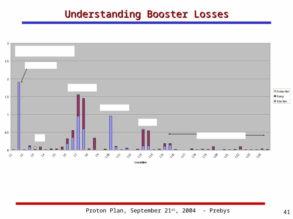
Proton Plan, September 21st, 2004 - Prebys 41
Understanding Booster LossesUnderstanding Booster Losses
0
0.5
1
1.5
2
2.5
3
L1 L2 L3 L4 L5 L6 L7 L8 L9 L10
L11
L12
L13
L14
L15
L16
L17
L18
L19
L20
L21
L22
L23
L24
Location
Extraction
Ramp
Injection
Collimators
Notch Loss
L13
L3 RF Region
Prompt Loss
After Collimators
Proton Plan, September 21st, 2004 - Prebys 42
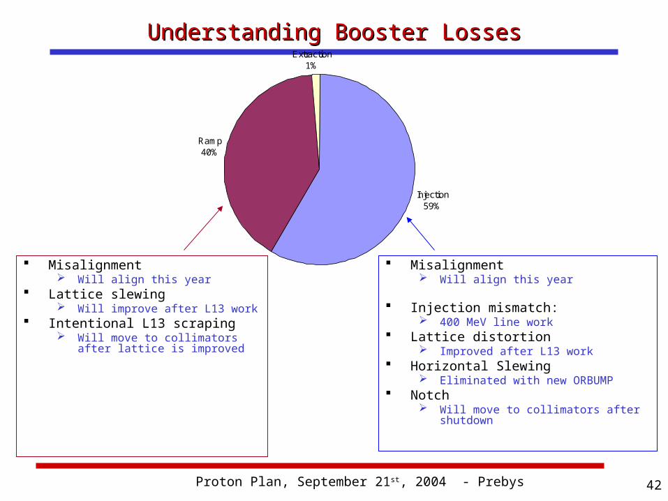
Understanding Booster LossesUnderstanding Booster Losses
Misalignment Will align this year
Lattice slewing Will improve after L13 work
Intentional L13 scraping Will move to collimators after
lattice is improved
Misalignment Will align this year
Injection mismatch: 400 MeV line work
Lattice distortion Improved after L13 work
Horizontal Slewing Eliminated with new ORBUMP
Notch Will move to collimators after
shutdown
Injection59%
Ramp40%
Extraction1%
Proton Plan, September 21st, 2004 - Prebys 43
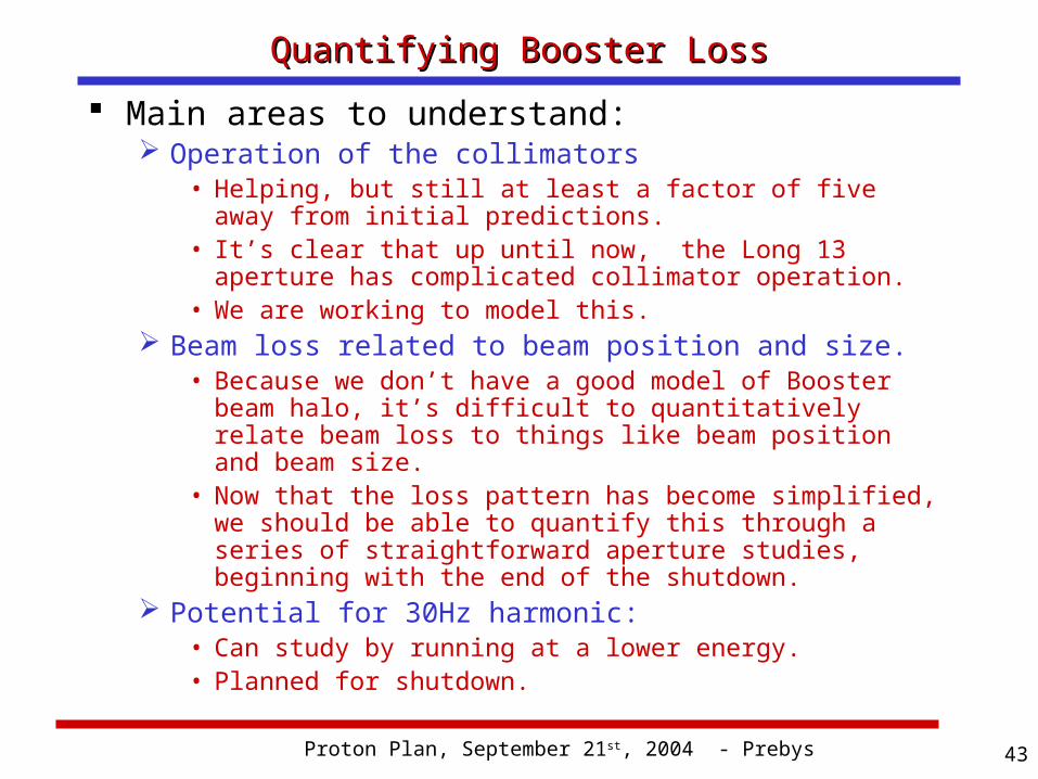
Quantifying Booster LossQuantifying Booster Loss Main areas to understand:
Operation of the collimators• Helping, but still at least a factor of five away from
initial predictions.• It’s clear that up until now, the Long 13 aperture has
complicated collimator operation.• We are working to model this.
Beam loss related to beam position and size.• Because we don’t have a good model of Booster beam
halo, it’s difficult to quantitatively relate beam loss to things like beam position and beam size.
• Now that the loss pattern has become simplified, we should be able to quantify this through a series of straightforward aperture studies, beginning with the end of the shutdown.
Potential for 30Hz harmonic:• Can study by running at a lower energy.• Planned for shutdown.
Proton Plan, September 21st, 2004 - Prebys 44
Summary and ConclusionsSummary and Conclusions The Proton Source has made remarkable
progress thanks to the work of countless people.
We believe we have a realistic plan to optimize the reliability and performance of the system over the next few years.
The main part of this plan involves the RF systems of the Booster and Main Injector, and the timescale of these projects is completely determined by how fast we spend money on them.