proton improvement plan pip - fermilab · this talk will focus on proton improvement plan’s ......
TRANSCRIPT
Proton Improvement Plan
PIP
Feb 4, 2014
William Pellico
Bob Zwaska
William Pellico, Bob Zwaska, Feb 4, 2014
Outline
This talk will focus on Proton Improvement Plan’s (PIP)
recent work and management. Historical reference will be
given to help give perspective of where we were and where
we are going.
Initialization
Why do we need PIP
Goals
First two years
Present Effort
Plans
Management and Controls
PIP structure
PIP controls
PIP planning
2
William Pellico, Bob Zwaska, Feb 4, 2014
3
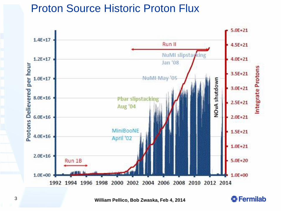
Proton Source Historic Proton Flux
William Pellico, Bob Zwaska, Feb 4, 2014
4
0
10
20
30
40
50
60
70
0
50
100
150
200
250
300
350
400
Inte
gra
ted
E19
Year
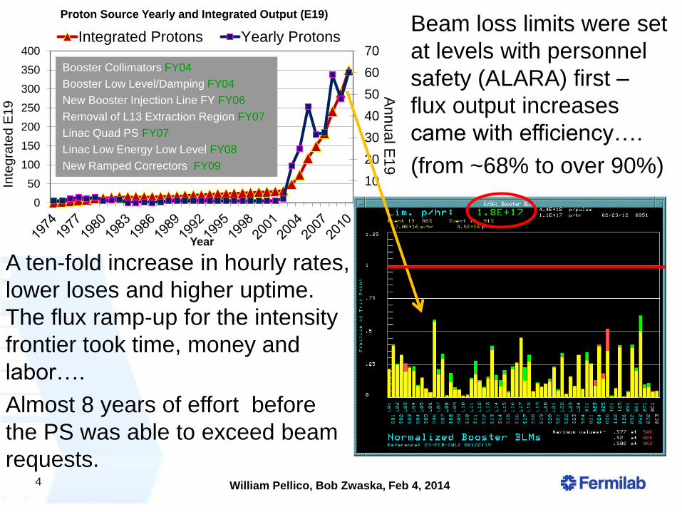
Proton Source Yearly and Integrated Output (E19)
Integrated Protons Yearly Protons
Annu
al E
19
Booster Collimators FY04
Booster Low Level/Damping FY04
New Booster Injection Line FY FY06
Removal of L13 Extraction Region FY07
Linac Quad PS FY07
Linac Low Energy Low Level FY08
New Ramped Correctors FY09
Loss Limit A ten-fold increase in hourly rates,
lower loses and higher uptime.
The flux ramp-up for the intensity
frontier took time, money and
labor….
Almost 8 years of effort before
the PS was able to exceed beam
requests.
Beam loss limits were set
at levels with personnel
safety (ALARA) first –
flux output increases
came with efficiency….
(from ~68% to over 90%)
William Pellico, Bob Zwaska, Feb 4, 2014
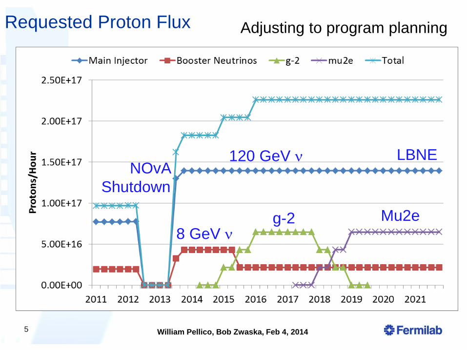
Requested Proton Flux
5
g-2 Mu2e 8 GeV
120 GeV NOvA
Shutdown
LBNE
Adjusting to program planning
William Pellico, Bob Zwaska, Feb 4, 2014
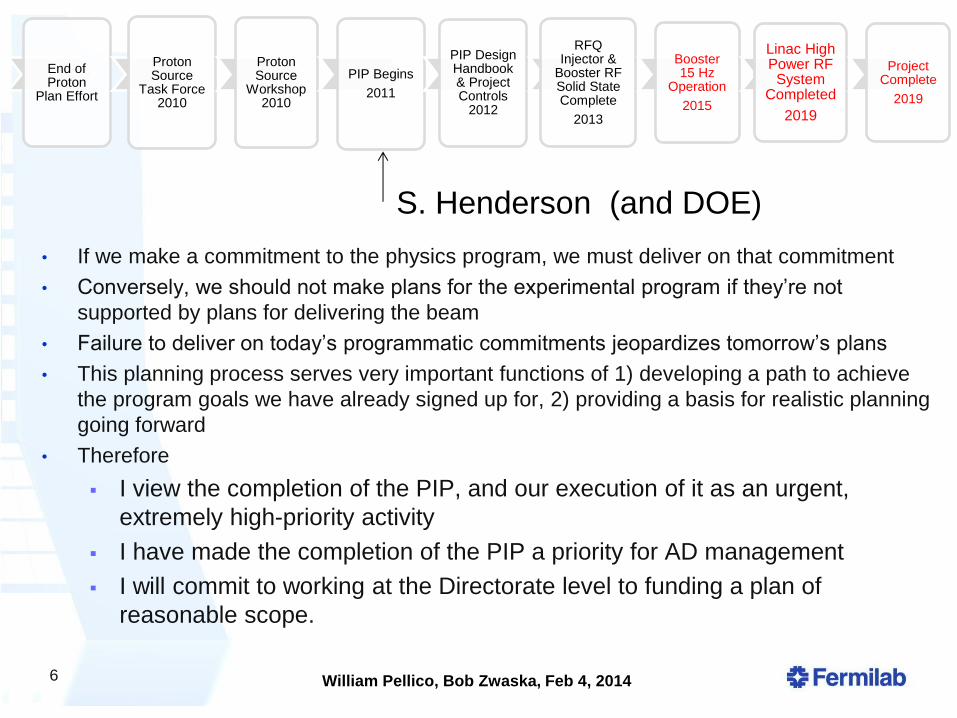
6
End of Proton
Plan Effort
Proton Source
Task Force 2010
Proton Source
Workshop 2010
PIP Begins
2011
PIP Design Handbook & Project Controls
2012
RFQ Injector &
Booster RF Solid State Complete
2013
Booster 15 Hz
Operation
2015
Linac High Power RF System
Completed
2019
Project Complete
2019
• If we make a commitment to the physics program, we must deliver on that commitment
• Conversely, we should not make plans for the experimental program if they’re not
supported by plans for delivering the beam
• Failure to deliver on today’s programmatic commitments jeopardizes tomorrow’s plans
• This planning process serves very important functions of 1) developing a path to achieve
the program goals we have already signed up for, 2) providing a basis for realistic planning
going forward
• Therefore
I view the completion of the PIP, and our execution of it as an urgent,
extremely high-priority activity
I have made the completion of the PIP a priority for AD management
I will commit to working at the Directorate level to funding a plan of
reasonable scope.
S. Henderson (and DOE)

William Pellico, Bob Zwaska, Feb 4, 2014
7
PIP – Original schedule
An aggressive 5 year plan
31 initial level 4 projects
Lots of documentation,
controls, meetings and
presentations
Work –
Can be divided into 3
parts:
Reliability/Viability
Flux
Cycle Repetition Rate
Lots has changed
Bob will give details ….
William Pellico, Bob Zwaska, Feb 4, 2014
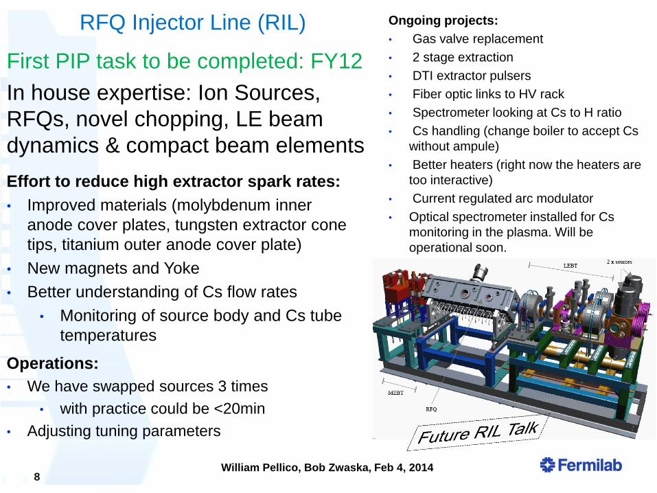
Effort to reduce high extractor spark rates:
• Improved materials (molybdenum inner
anode cover plates, tungsten extractor cone
tips, titanium outer anode cover plate)
• New magnets and Yoke
• Better understanding of Cs flow rates
• Monitoring of source body and Cs tube
temperatures
Operations:
• We have swapped sources 3 times
• with practice could be <20min
• Adjusting tuning parameters
RFQ Injector Line (RIL) Ongoing projects:
• Gas valve replacement
• 2 stage extraction
• DTI extractor pulsers
• Fiber optic links to HV rack
• Spectrometer looking at Cs to H ratio
• Cs handling (change boiler to accept Cs
without ampule)
• Better heaters (right now the heaters are
too interactive)
• Current regulated arc modulator
• Optical spectrometer installed for Cs
monitoring in the plasma. Will be
operational soon.
8
First PIP task to be completed: FY12
In house expertise: Ion Sources,
RFQs, novel chopping, LE beam
dynamics & compact beam elements
William Pellico, Bob Zwaska, Feb 4, 2014
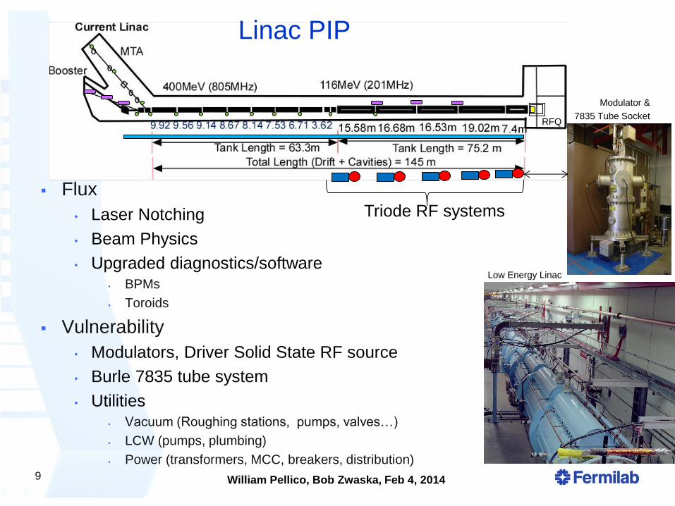
PIP - Linac
Flux
• Laser Notching
• Beam Physics
• Upgraded diagnostics/software BPMs
Toroids
Vulnerability
• Modulators, Driver Solid State RF source
• Burle 7835 tube system
• Utilities Vacuum (Roughing stations, pumps, valves…)
LCW (pumps, plumbing)
Power (transformers, MCC, breakers, distribution)
9
RFQ
Linac PIP
Modulator &
7835 Tube Socket
Low Energy Linac
Triode RF systems
William Pellico, Bob Zwaska, Feb 4, 2014
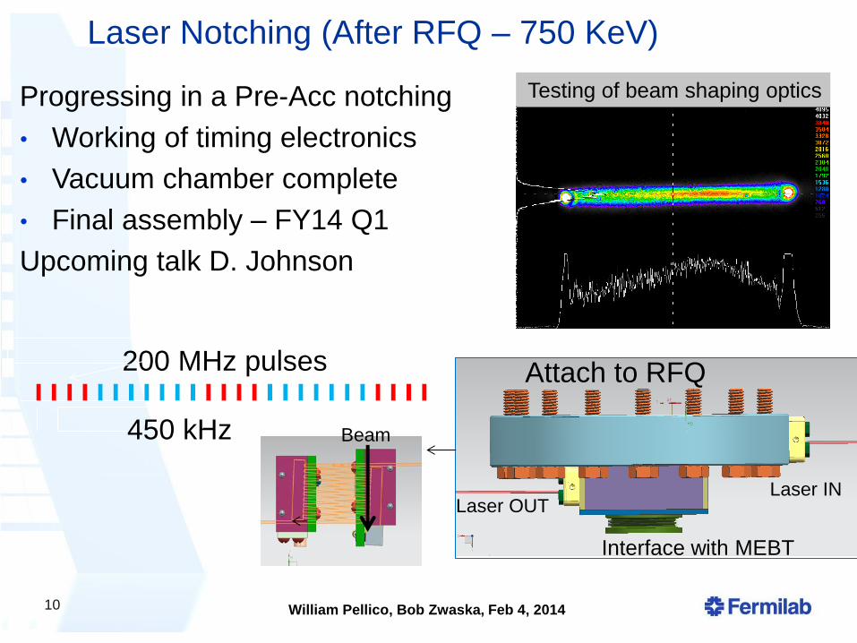
Laser Notching (After RFQ – 750 KeV)
10
Attach to RFQ
Laser IN Laser OUT
Interface with MEBT
200 MHz pulses
450 kHz
Progressing in a Pre-Acc notching
• Working of timing electronics
• Vacuum chamber complete
• Final assembly – FY14 Q1
Upcoming talk D. Johnson
Testing of beam shaping optics
Beam
William Pellico, Bob Zwaska, Feb 4, 2014
Linac Beam Physics
Goals: To obtain accurate on line Linac model from RFQ injector
to Booster injection (foils).
Generate beam envelope (Twiss-Parm) - emittance and efficiency
TRACEWIN, TOUTATIS, PARMILA, PARMTEQM and MAD
Optimize quad settings, loss reduction and ability to find new
settings when a quad fails inside DTL tank.
PIP Linac Physics work has made big improvements and
continues to add to previous efforts
Not done – accurate model still not completed 11
William Pellico, Bob Zwaska, Feb 4, 2014
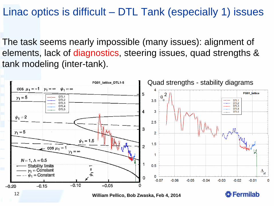
Linac optics is difficult – DTL Tank (especially 1) issues
12
Quad strengths - stability diagrams
The task seems nearly impossible (many issues): alignment of
elements, lack of diagnostics, steering issues, quad strengths &
tank modeling (inter-tank).
William Pellico, Bob Zwaska, Feb 4, 2014
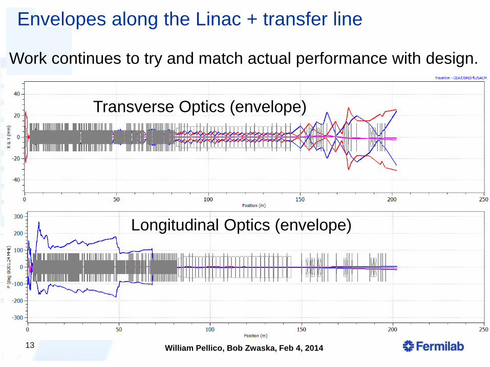
Envelopes along the Linac + transfer line
13
Work continues to try and match actual performance with design.
Transverse Optics (envelope)
Longitudinal Optics (envelope)
William Pellico, Bob Zwaska, Feb 4, 2014
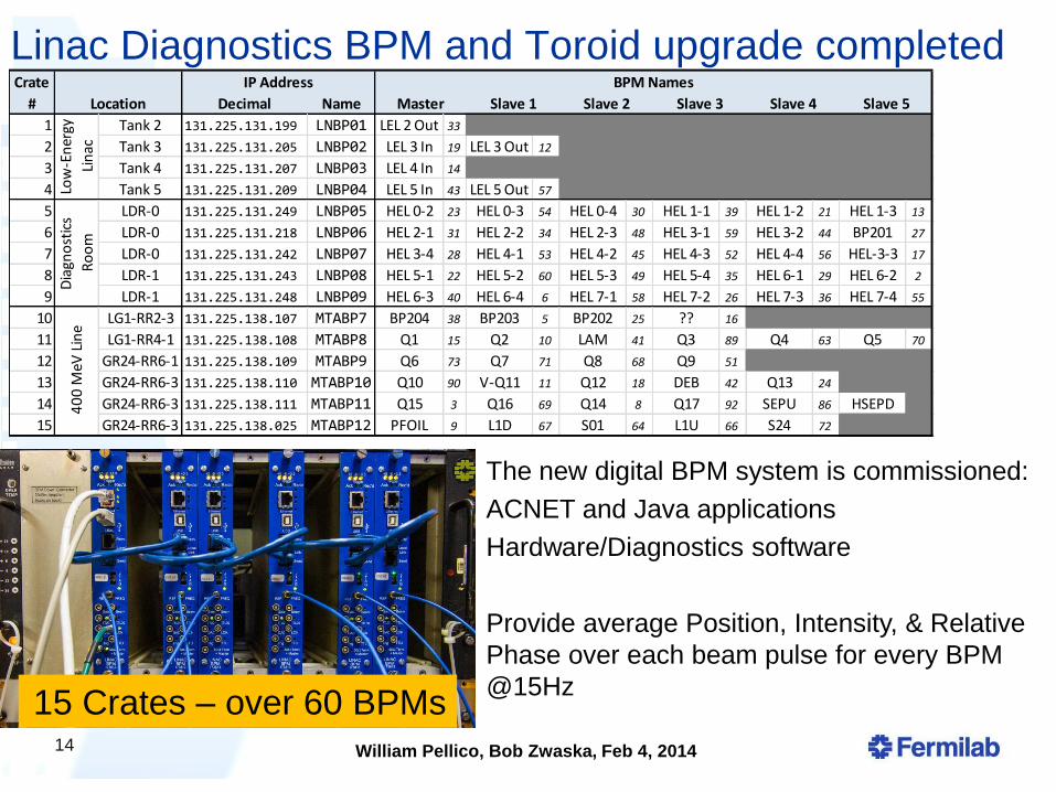
Linac Diagnostics BPM and Toroid upgrade completed
14
Decimal Name
1 Tank 2 131.225.131.199 LNBP01 LEL 2 Out 33 0 0 0 0 0 0 0 0 0 0
2 Tank 3 131.225.131.205 LNBP02 LEL 3 In 19 LEL 3 Out 12 0 0 0 0 0 0 0 0
3 Tank 4 131.225.131.207 LNBP03 LEL 4 In 14 0 0 0 0 0 0 0 0 0 0
4 Tank 5 131.225.131.209 LNBP04 LEL 5 In 43 LEL 5 Out 57 0 0 0 0 0 0 0 0
5 LDR-0 131.225.131.249 LNBP05 HEL 0-2 23 HEL 0-3 54 HEL 0-4 30 HEL 1-1 39 HEL 1-2 21 HEL 1-3 13
6 LDR-0 131.225.131.218 LNBP06 HEL 2-1 31 HEL 2-2 34 HEL 2-3 48 HEL 3-1 59 HEL 3-2 44 BP201 27
7 LDR-0 131.225.131.242 LNBP07 HEL 3-4 28 HEL 4-1 53 HEL 4-2 45 HEL 4-3 52 HEL 4-4 56 HEL-3-3 17
8 LDR-1 131.225.131.243 LNBP08 HEL 5-1 22 HEL 5-2 60 HEL 5-3 49 HEL 5-4 35 HEL 6-1 29 HEL 6-2 2
9 LDR-1 131.225.131.248 LNBP09 HEL 6-3 40 HEL 6-4 6 HEL 7-1 58 HEL 7-2 26 HEL 7-3 36 HEL 7-4 55
10 LG1-RR2-3 131.225.138.107 MTABP7 BP204 38 BP203 5 BP202 25 ?? 16 0 0 0 0
11 LG1-RR4-1 131.225.138.108 MTABP8 Q1 15 Q2 10 LAM 41 Q3 89 Q4 63 Q5 70
12 GR24-RR6-1 131.225.138.109 MTABP9 Q6 73 Q7 71 Q8 68 Q9 51 0 0 0 0
13 GR24-RR6-3 131.225.138.110 MTABP10 Q10 90 V-Q11 11 Q12 18 DEB 42 Q13 24 0 0
14 GR24-RR6-3 131.225.138.111 MTABP11 Q15 3 Q16 69 Q14 8 Q17 92 SEPU 86 HSEPD 0
15 GR24-RR6-3 131.225.138.025 MTABP12 PFOIL 9 L1D 67 S01 64 L1U 66 S24 72 0 0
IP Address BPM Names
Master Slave 1 Slave 2 Slave 3 Slave 4 Slave 5
Low
-En
ergy
Lin
ac
Dia
gno
stic
s
Ro
om
40
0 M
eV L
ine
Location
Crate
#
The new digital BPM system is commissioned:
ACNET and Java applications
Hardware/Diagnostics software
Provide average Position, Intensity, & Relative
Phase over each beam pulse for every BPM
@15Hz 15 Crates – over 60 BPMs
William Pellico, Bob Zwaska, Feb 4, 2014
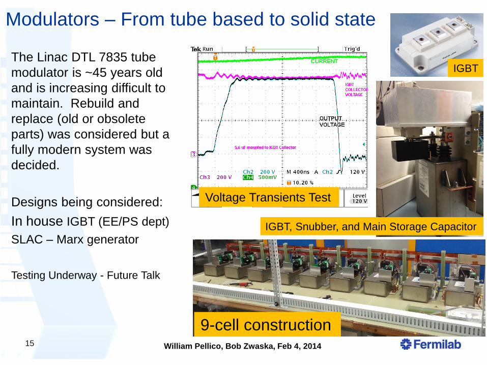
Modulators – From tube based to solid state
15
9-cell construction
IGBT, Snubber, and Main Storage Capacitor
IGBT
Voltage Transients Test
The Linac DTL 7835 tube
modulator is ~45 years old
and is increasing difficult to
maintain. Rebuild and
replace (old or obsolete
parts) was considered but a
fully modern system was
decided.
Designs being considered:
In house IGBT (EE/PS dept)
SLAC – Marx generator
Testing Underway - Future Talk
William Pellico, Bob Zwaska, Feb 4, 2014
Linac 200 MHz Power Systems
7835 triode
16
The high power RF 7835 tube is a Linac vulnerability with
reliability issues. This has been a concern for many years for
FNAL and other laboratories. After considering several options
which looked at cost, labor, schedules and risk, a plan was
developed and approved by laboratory management.
1. The buildup of a 4 year 7835 inventory
2. To design and build a new solid state modulator (keep 7835)
3. Replace tube systems in driver with Solid State when possible
4. Investigate 7835 replacement
1. Investigate LANL option
2. Investigate Klystron option
1. Budget and plan for prototype with eventual system option
William Pellico, Bob Zwaska, Feb 4, 2014
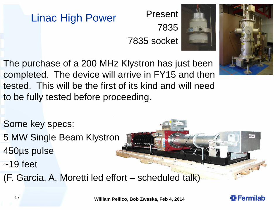
Linac High Power
17
The purchase of a 200 MHz Klystron has just been
completed. The device will arrive in FY15 and then
tested. This will be the first of its kind and will need
to be fully tested before proceeding.
Some key specs:
5 MW Single Beam Klystron
450µs pulse
~19 feet
(F. Garcia, A. Moretti led effort – scheduled talk)
Present
7835
7835 socket
William Pellico, Bob Zwaska, Feb 4, 2014
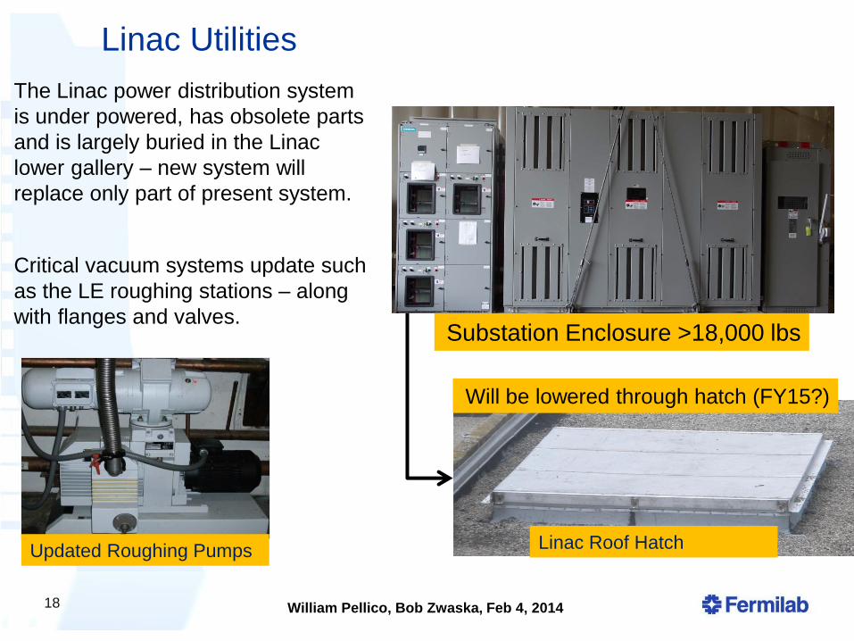
Linac Utilities
18
Substation Enclosure >18,000 lbs
Updated Roughing Pumps Linac Roof Hatch
Will be lowered through hatch (FY15?)
The Linac power distribution system
is under powered, has obsolete parts
and is largely buried in the Linac
lower gallery – new system will
replace only part of present system.
Critical vacuum systems update such
as the LE roughing stations – along
with flanges and valves.
William Pellico, Bob Zwaska, Feb 4, 2014
Booster PIP 15 Hz operation
RF cavity refurbishment
Bias Supplies
Anode Supplies
Flux
Beam Physics
• Optics and Alignment
• Cogging
Notch System
Collimation
RF Harmonic
Dampers
Shielding
Reliability
RF Solid State
Low Level Upgrades
RF Cavities and tuners
Utilities (LCW, Power Systems, Vacuum)
BPMs
19
Booster
Many tasks have multiple benefits
- Reliability, Flux, 15Hz operation
but also skills and accelerator
technology
William Pellico, Bob Zwaska, Feb 4, 2014
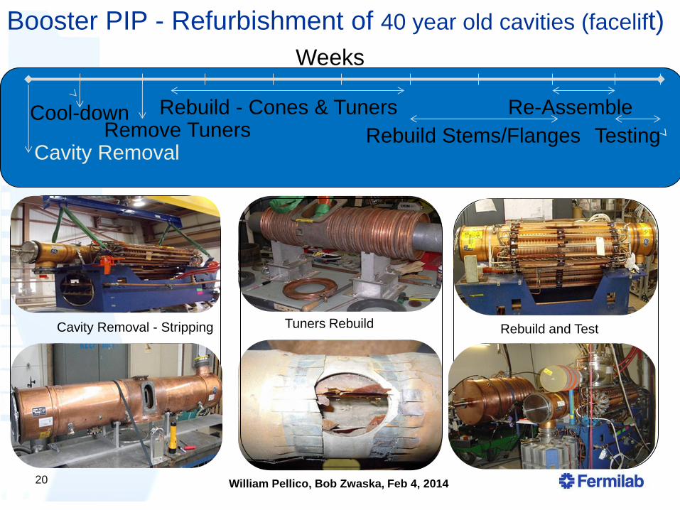
Booster PIP - Refurbishment of 40 year old cavities (facelift)
20
Cavity Removal
Cool-down Remove Tuners
Rebuild - Cones & Tuners
Rebuild Stems/Flanges
Re-Assemble
Testing
Weeks
Cavity Removal - Stripping Tuners Rebuild Rebuild and Test
William Pellico, Bob Zwaska, Feb 4, 2014
Refurbishment - continued
21
Fun Facts
You need all cavities in tunnel to be refurbished before higher rep
rate operations
After refurbishment is completed – higher flux will require time
After refurbishment is completed – the cavities will still be OLD
There is likely to be failures as cavities are run harder
Talk at later date by Matt Slabaugh and John Reid
William Pellico, Bob Zwaska, Feb 4, 2014
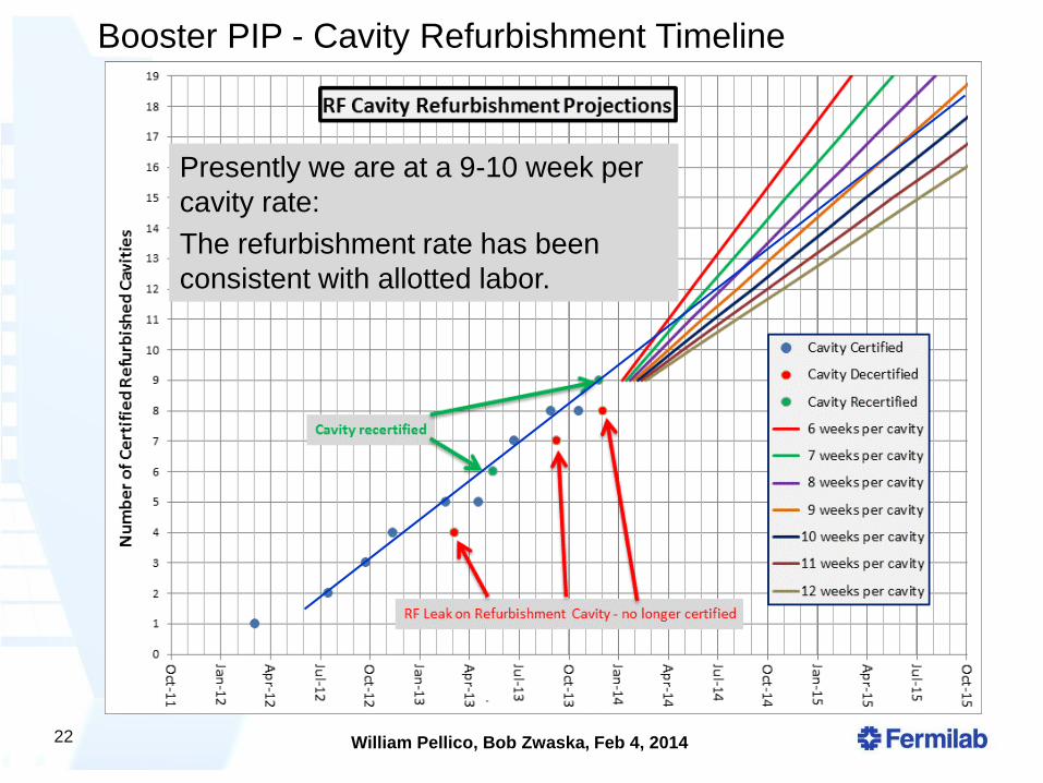
22
Presently we are at a 9-10 week per
cavity rate:
The refurbishment rate has been
consistent with allotted labor.
Booster PIP - Cavity Refurbishment Timeline
William Pellico, Bob Zwaska, Feb 4, 2014
Anode Supplies and Bias Supplies (15 Hz operation)
23
Anode
Modern
Refurbishment Bias Transformer
Heat Sinks
LCW Power Distribution
Solid State Drive System
Design is nearly complete
Install this summer both
anode supplies: (EE / RF
Dept.)
East gallery complete
West gallery supplies
work underway but slow –
will be finished FY15
Completed Completed Completed
William Pellico, Bob Zwaska, Feb 4, 2014
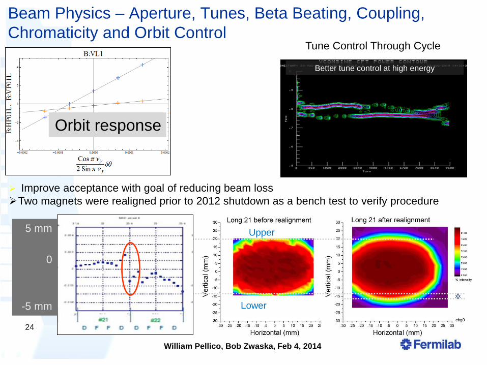
Beam Physics – Aperture, Tunes, Beta Beating, Coupling,
Chromaticity and Orbit Control
24
Upper
Lower
5 mm
0
-5 mm
Improve acceptance with goal of reducing beam loss
Two magnets were realigned prior to 2012 shutdown as a bench test to verify procedure
Orbit response
Better tune control at high energy
Tune Control Through Cycle
William Pellico, Bob Zwaska, Feb 4, 2014
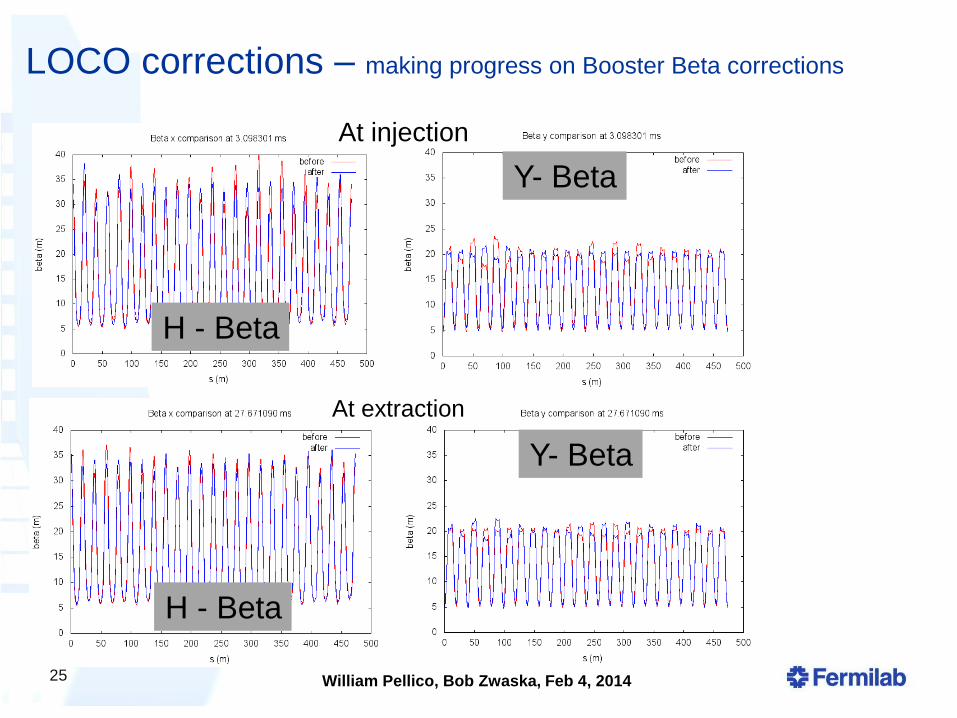
LOCO corrections – making progress on Booster Beta corrections
At injection
At extraction
25
Y- Beta
Y- Beta
H - Beta
H - Beta
William Pellico, Bob Zwaska, Feb 4, 2014
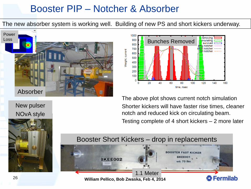
Booster PIP – Notcher & Absorber
26
The new absorber system is working well. Building of new PS and short kickers underway.
The above plot shows current notch simulation
Shorter kickers will have faster rise times, cleaner
notch and reduced kick on circulating beam.
Testing complete of 4 short kickers – 2 more later
New pulser
NOvA style
Booster Short Kickers – drop in replacements
Absorber
1.1 Meter
Bunches Removed
Power
Loss
William Pellico, Bob Zwaska, Feb 4, 2014
27
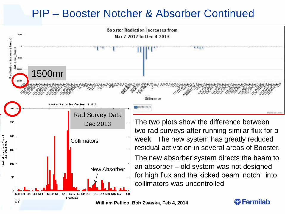
The two plots show the difference between
two rad surveys after running similar flux for a
week. The new system has greatly reduced
residual activation in several areas of Booster.
The new absorber system directs the beam to
an absorber – old system was not designed
for high flux and the kicked beam ‘notch’ into
collimators was uncontrolled
PIP – Booster Notcher & Absorber Continued
Rad Survey Data
Dec 2013
New Absorber
Collimators
1500mr
William Pellico, Bob Zwaska, Feb 4, 2014
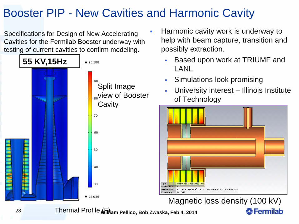
Booster PIP - New Cavities and Harmonic Cavity
Harmonic cavity work is underway to
help with beam capture, transition and
possibly extraction.
Based upon work at TRIUMF and
LANL
Simulations look promising
University interest – Illinois Institute
of Technology
28
Specifications for Design of New Accelerating
Cavities for the Fermilab Booster underway with
testing of current cavities to confirm modeling.
55 KV,15Hz
Thermal Profile (F)
Split Image
view of Booster
Cavity
Magnetic loss density (100 kV)
William Pellico, Bob Zwaska, Feb 4, 2014
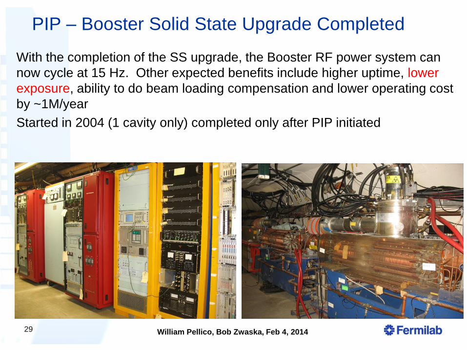
PIP – Booster Solid State Upgrade Completed
29
With the completion of the SS upgrade, the Booster RF power system can
now cycle at 15 Hz. Other expected benefits include higher uptime, lower
exposure, ability to do beam loading compensation and lower operating cost
by ~1M/year
Started in 2004 (1 cavity only) completed only after PIP initiated
William Pellico, Bob Zwaska, Feb 4, 2014
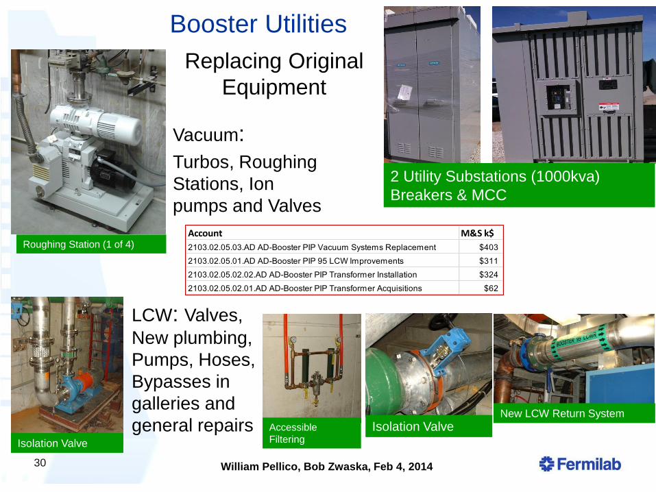
Booster Utilities
30
LCW: Valves,
New plumbing,
Pumps, Hoses,
Bypasses in
galleries and
general repairs New LCW Return System
2 Utility Substations (1000kva)
Breakers & MCC
Account M&S k$
2103.02.05.03.AD AD-Booster PIP Vacuum Systems Replacement $403
2103.02.05.01.AD AD-Booster PIP 95 LCW Improvements $311
2103.02.05.02.02.AD AD-Booster PIP Transformer Installation $324
2103.02.05.02.01.AD AD-Booster PIP Transformer Acquisitions $62
Isolation Valve Accessible
Filtering Isolation Valve
Roughing Station (1 of 4)
Vacuum:
Turbos, Roughing
Stations, Ion
pumps and Valves
Replacing Original
Equipment
William Pellico, Bob Zwaska, Feb 4, 2014
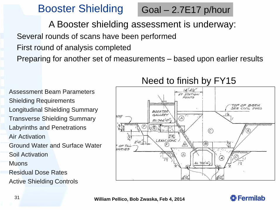
Booster Shielding
31
Assessment Beam Parameters
Shielding Requirements
Longitudinal Shielding Summary
Transverse Shielding Summary
Labyrinths and Penetrations
Air Activation
Ground Water and Surface Water
Soil Activation
Muons
Residual Dose Rates
Active Shielding Controls
A Booster shielding assessment is underway:
Several rounds of scans have been performed
First round of analysis completed
Preparing for another set of measurements – based upon earlier results
Goal – 2.7E17 p/hour
Need to finish by FY15

32
William Pellico, Bob Zwaska, Feb 4, 2014
What is a project?
Angst of what is, and what is not a “project” Jargon of “project-lite”
DOE O 413.3b applies to only a very narrow subset of projects Large “acquisition of capital assets”, or construction projects
In general (outside of DOE-world), projects are efforts with a temporary existence and specific goals PIP is a project! (by any conventional definition)
So, how does PIP fit into our understanding of projects from DOE? PIP is supported by operations and applies to existing
machines
Previously, this may have been termed a campaign or program
Regardless of the above, PIP must implement a project management methodology to be successful, though not specifically covered by 413.3b
This will be an interesting (subjectively) study of how to manage a major project outside 413.3b
33
William Pellico, Bob Zwaska, Feb 4, 2014
Managing PIP
Developed useful processes that are familiar, though different than 413.3b PIP Project Management Plan
• c.f. Project Execution/Implementation Plans
PIP Design Handbook
• c.f. CDR / TDR
Cost/Schedule
• Bottoms-up RLS
Reporting
• Regular reports
• PMGs
Had input from lab management, DOE, project
34
William Pellico, Bob Zwaska, Feb 4, 2014
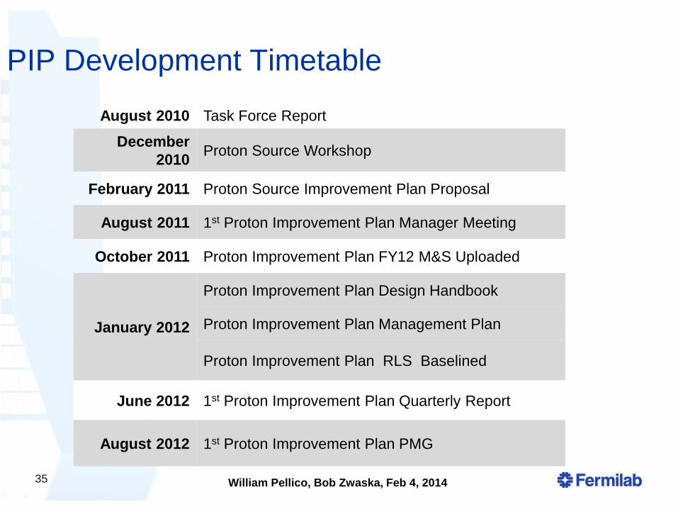
PIP Development Timetable
August 2010 Task Force Report
December
2010 Proton Source Workshop
February 2011 Proton Source Improvement Plan Proposal
August 2011 1st Proton Improvement Plan Manager Meeting
October 2011 Proton Improvement Plan FY12 M&S Uploaded
January 2012
Proton Improvement Plan Design Handbook
Proton Improvement Plan Management Plan
Proton Improvement Plan RLS Baselined
June 2012 1st Proton Improvement Plan Quarterly Report
August 2012 1st Proton Improvement Plan PMG
35
William Pellico, Bob Zwaska, Feb 4, 2014
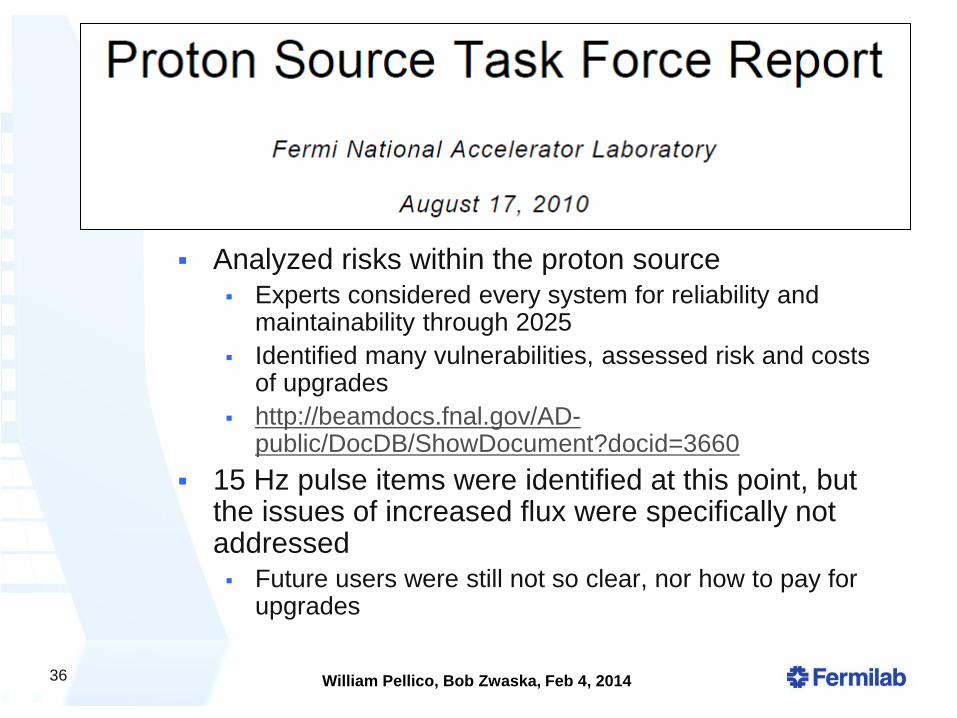
Report
Analyzed risks within the proton source
Experts considered every system for reliability and maintainability through 2025
Identified many vulnerabilities, assessed risk and costs of upgrades
http://beamdocs.fnal.gov/AD-public/DocDB/ShowDocument?docid=3660
15 Hz pulse items were identified at this point, but the issues of increased flux were specifically not addressed
Future users were still not so clear, nor how to pay for upgrades
36
William Pellico, Bob Zwaska, Feb 4, 2014
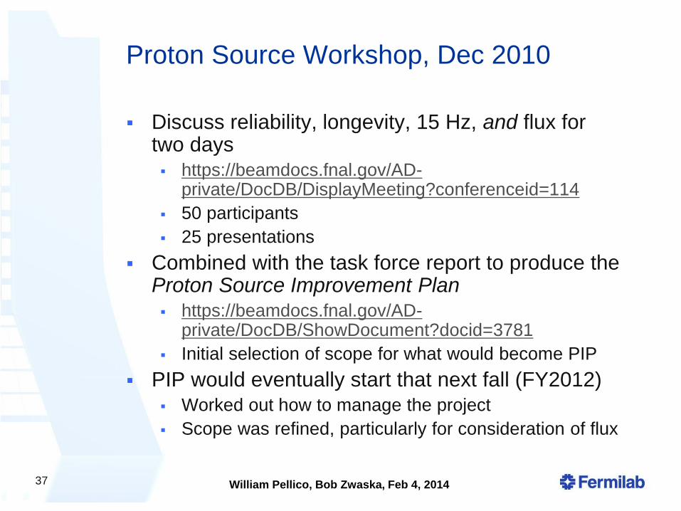
Proton Source Workshop, Dec 2010
Discuss reliability, longevity, 15 Hz, and flux for two days
https://beamdocs.fnal.gov/AD-private/DocDB/DisplayMeeting?conferenceid=114
50 participants
25 presentations
Combined with the task force report to produce the Proton Source Improvement Plan
https://beamdocs.fnal.gov/AD-private/DocDB/ShowDocument?docid=3781
Initial selection of scope for what would become PIP
PIP would eventually start that next fall (FY2012)
Worked out how to manage the project
Scope was refined, particularly for consideration of flux
37
William Pellico, Bob Zwaska, Feb 4, 2014
PIP Project
Management Plan
Derived from implementation
and execution plans
https://beamdocs.fnal.gov/AD-
private/DocDB/ShowDocument?
docid=4052
Spells out the basic practices
for the project
Still run the project off of this
document
38
William Pellico, Bob Zwaska, Feb 4, 2014
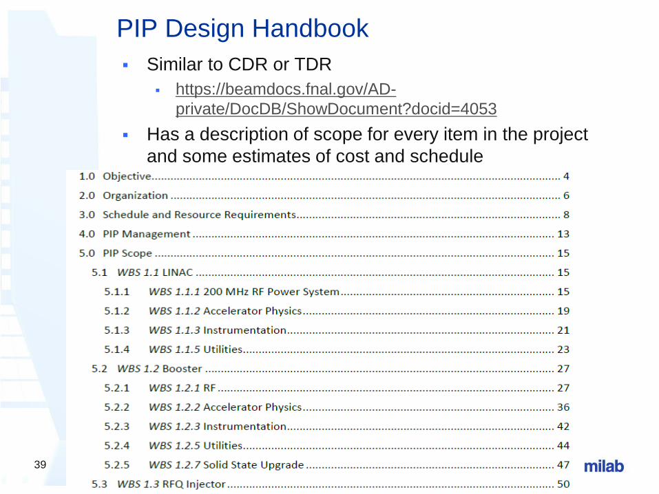
PIP Design Handbook
Similar to CDR or TDR
https://beamdocs.fnal.gov/AD-
private/DocDB/ShowDocument?docid=4053
Has a description of scope for every item in the project
and some estimates of cost and schedule
39
William Pellico, Bob Zwaska, Feb 4, 2014
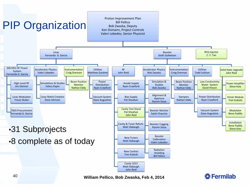
PIP Organization
40
Proton Improvement Plan Bill Pellico
Bob Zwaska, Deputy Ken Domann, Project Controls
Valeri Lebedev, Senior Physicist
Linac Fernanda G. Garcia
200 MHz RF Power System
Fernanda G. Garcia
High-Level RF Jim Steimel
Linac Modulator Trevor Butler
7835 Procurement Fernanda G. Garcia
Accelerator Physics Valeri Lebedev
Simulations & Studies Valery Kapin
Linac Notch Creation Dave Johnson
Instrumentation Craig Drennan
Beam Position Monitor
Nathan Eddy
Utilities Matthew Gardner
Power Distribution
Ryan Crawford
Vacuum System Dave Augustine
Booster Keith Gollwitzer
RF John Reid
Anode Supply Ryan Crawford
Bias Supply Pat Sheahan
Cavity Test Stand Pat Sheahan
John Reid
Cavity & Tuner Refurb. Matt Slabaugh
New Tuners Matt Slabaugh
New Cavities Tom Kubicki
Cavity 1013 Matt Slabaugh
John Reid
Accelerator Physics Bob Zwaska
Simulation & Studies
Bob Zwaska
Alignment & Aperture
Kiyomi Seiya
Booster Notcher Salah Chaurize
Booster Cogging Kiyomi Seiya
Booster Collimation
Valeri Lebedev
Radiation Shielding Bill Pellico
Instrumentation Craig Drennan
Beam Position Monitor
Nathan Eddy
Dampers Nathan Eddy
Utilities Todd Sullivan
Low-Conductivity Water System David Hixson
Power Distribution Ryan Crawford
Vacuum System Dave Augustine
Solid State Upgrade John Reid
Power Amplifier Steve Kotz
Driver Module Tom Kubicki
Modulator Rene Padilla
Installation Rene Padilla Steve Kotz
RFQ Injector C. Y. Tan
•31 Subprojects
•8 complete as of today
William Pellico, Bob Zwaska, Feb 4, 2014
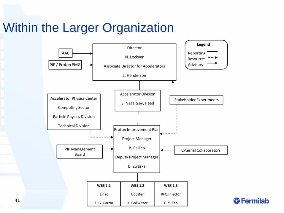
Within the Larger Organization
WBS 1.3
RFQ Injector
C. Y. Tan
Accelerator Division
S. Nagaitsev, Head
PIP Management Board
PIP / Proton PMG
Director
N. Lockyer
Associate Director for Accelerators
S. Henderson
Proton Improvement Plan
Project Manager
B. Pellico
Deputy Project Manager
B. Zwaska
WBS 1.1
Linac
F. G. Garcia
WBS 1.2
Booster
K. Gollwitzer
AAC
Accelerator Physics Center
Computing Sector
Particle Physics Division
Technical Division
Stakeholder Experiments
External Collaborators
Legend
Reporting
Resources
Advisory
41
William Pellico, Bob Zwaska, Feb 4, 2014
Project Management Board
Stays in constant communication over all aspects of the process Technical – financial – managerial
Composed of project “office” & L2s Pellico, Zwaska, Domann, Lebedev, Garcia,
Gollwitzer
• All part-time
• Team approach allows us to stand in for each other
Previously also: Tan, Evans-Peoples, Convery (Webber)
Small, consistent group eases flow of information
42
William Pellico, Bob Zwaska, Feb 4, 2014
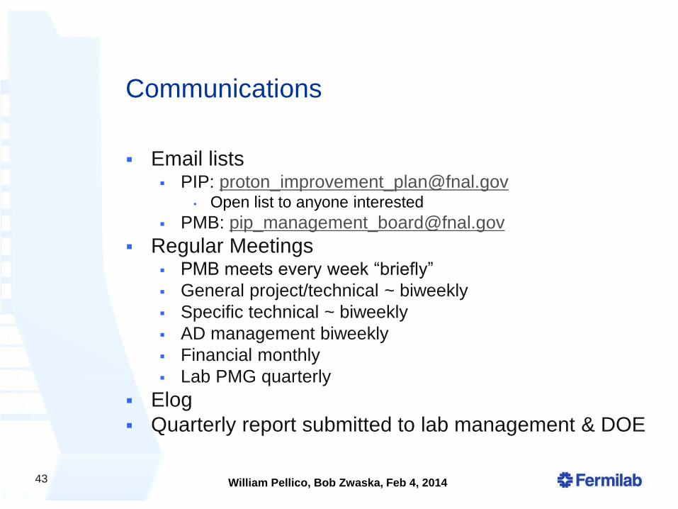
Communications
Email lists PIP: [email protected]
• Open list to anyone interested
PMB: [email protected]
Regular Meetings PMB meets every week “briefly”
General project/technical ~ biweekly
Specific technical ~ biweekly
AD management biweekly
Financial monthly
Lab PMG quarterly
Elog
Quarterly report submitted to lab management & DOE
43
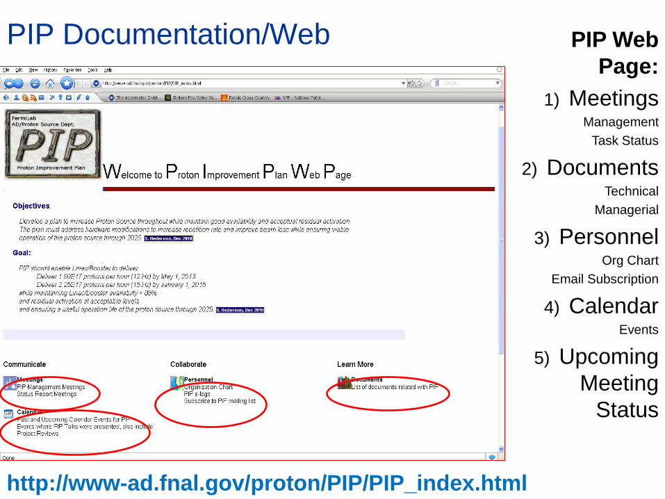
PIP Documentation/Web
http://www-ad.fnal.gov/proton/PIP/PIP_index.html
PIP Web
Page:
1) Meetings Management
Task Status
2) Documents Technical
Managerial
3) Personnel Org Chart
Email Subscription
4) Calendar Events
5) Upcoming
Meeting
Status
William Pellico, Bob Zwaska, Feb 4, 2014
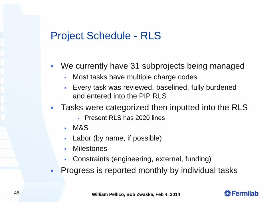
Project Schedule - RLS
We currently have 31 subprojects being managed
Most tasks have multiple charge codes
Every task was reviewed, baselined, fully burdened
and entered into the PIP RLS
Tasks were categorized then inputted into the RLS • Present RLS has 2020 lines
M&S
Labor (by name, if possible)
Milestones
Constraints (engineering, external, funding)
Progress is reported monthly by individual tasks
45
William Pellico, Bob Zwaska, Feb 4, 2014
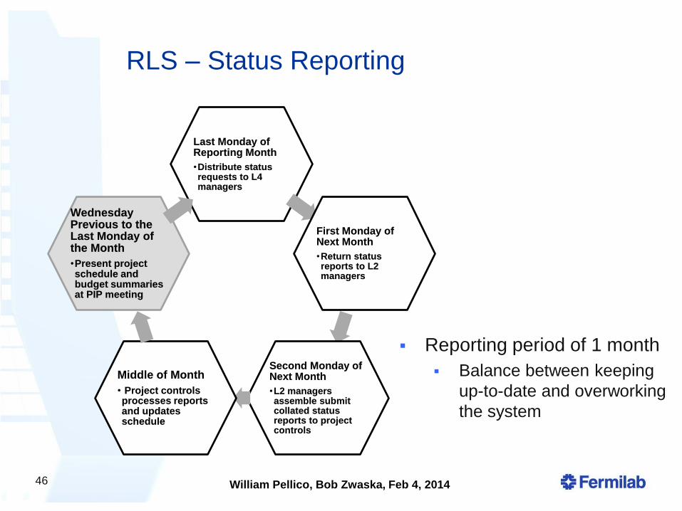
RLS – Status Reporting
Last Monday of Reporting Month
•Distribute status requests to L4 managers
First Monday of Next Month
•Return status reports to L2 managers
Second Monday of Next Month
•L2 managers assemble submit collated status reports to project controls
Middle of Month
• Project controls processes reports and updates schedule
Wednesday Previous to the Last Monday of the Month
•Present project schedule and budget summaries at PIP meeting
46
Reporting period of 1 month
Balance between keeping
up-to-date and overworking
the system
William Pellico, Bob Zwaska, Feb 4, 2014
RLS – Tracking Progress
Budget Reports Issued on a monthly basis from AD Headquarters
Used to load M&S and SWF actuals into RLS
Each month actual and status values are computed and compared to the schedule (EVMS quantities)
Effort Reports Issued on a weekly basis from AD Headquarters
Compare labor effort to plan and verify SWF charges (people reporting appropriately)
Determine FTE % to compare to labor allocations • Useful in discussions with departments and divisions
about labor
• Getting labor matrixed in to the project is often complicated and/or difficult
All reported at a monthly project-wide meeting
47
William Pellico, Bob Zwaska, Feb 4, 2014
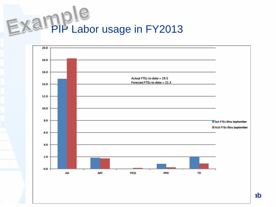
PIP Labor usage in FY2013
William Pellico, Bob Zwaska, Feb 4, 2014
Budgeting
A great difficulty for PIP has been how to account for budget and how the funding profile is managed
Budget methodology: PIP (with lab & DOE guidance) was initially budgeted with direct
M&S and FTE counts • Note: division budgets are in direct dollars
Next iteration was with burdened M&S and FTE counts
Finally, we settled on a TPC-like number of burdened M&S and SWF
Funding profile further complicated Translation between budget types was not obvious
Profile changes several times a year • We have to adjust schedule continuously
What was initially a 5-yr project now appears to be 7 or 8
Financial support provided through the AD division office Meet on a regular basis and take part in all divisional and lab-
wide budgeting exercises
Budget authority list established for different level managers
49
William Pellico, Bob Zwaska, Feb 4, 2014
Reviews
Various scales of technical reviews applied to
efforts
Major items get specific reviews with external panels
• For example: RFQ, L13 Absorber, klystron, cavities, …
Numerous internal reviews of subprojects
• At specific or project-wide meetings
Individual items are subject to engineering reviews,
usually within their departments
Schedule and budget reviews held periodically
within the project, usually by the PMB
RLS was recently completely updated – review is
pending
50
William Pellico, Bob Zwaska, Feb 4, 2014
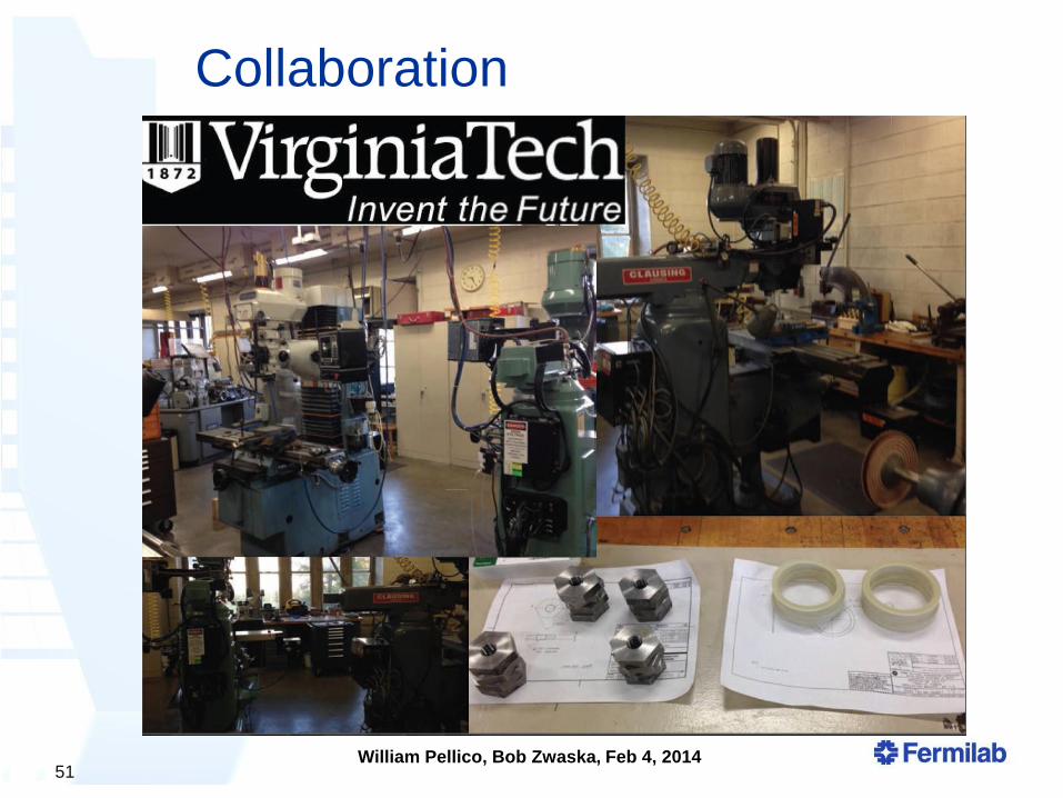
Collaboration
Technical coordination with other labs: BNL on RFQ Injector
LANL on 200 MHZ power amplifiers
SLAC on klystrons and modulators
ANL on several items
Ideally, would collaborate with interested institutions from experiments Distributed a list with ~ 40 topics for collaboration to all
relevant experiments • Effort nature: Scientific, Technical, or Machining
Some initial interest expressed
A few pieces built at Virginia Tech • Now hampered by DOE “loan” rules
Few more collaboration items on the table, but has not really developed without a model / system for involvement
51
William Pellico, Bob Zwaska, Feb 4, 2014
Conclusion
52
• PIP has been proceeding since it’s startup in
FY12
• Project structure built to suit
• Issues with funding have required flexibility and delays
in the final PIP completion date
• Several technical achievements already complete
in the project
• RFQ, Solid-State, Notch Absorber, Utilities
• Laboratory prioritization will continue to be the
determining factor in what PIP does and
completion dates
• New Cavities
• Klystrons
• Linac Modulators
William Pellico, Bob Zwaska, Feb 4, 2014
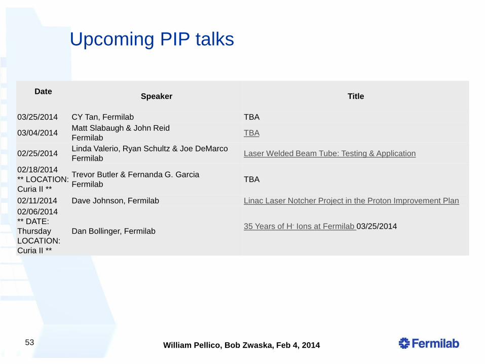
Upcoming PIP talks
53
Date
Speaker
Title
03/25/2014 CY Tan, Fermilab TBA
03/04/2014 Matt Slabaugh & John Reid
Fermilab TBA
02/25/2014 Linda Valerio, Ryan Schultz & Joe DeMarco
Fermilab Laser Welded Beam Tube: Testing & Application
02/18/2014
** LOCATION:
Curia II **
Trevor Butler & Fernanda G. Garcia
Fermilab TBA
02/11/2014 Dave Johnson, Fermilab Linac Laser Notcher Project in the Proton Improvement Plan
02/06/2014
** DATE:
Thursday
LOCATION:
Curia II **
Dan Bollinger, Fermilab 35 Years of H- Ions at Fermilab 03/25/2014
Xtra Slides
William Pellico, Bob Zwaska, Feb 4, 2014
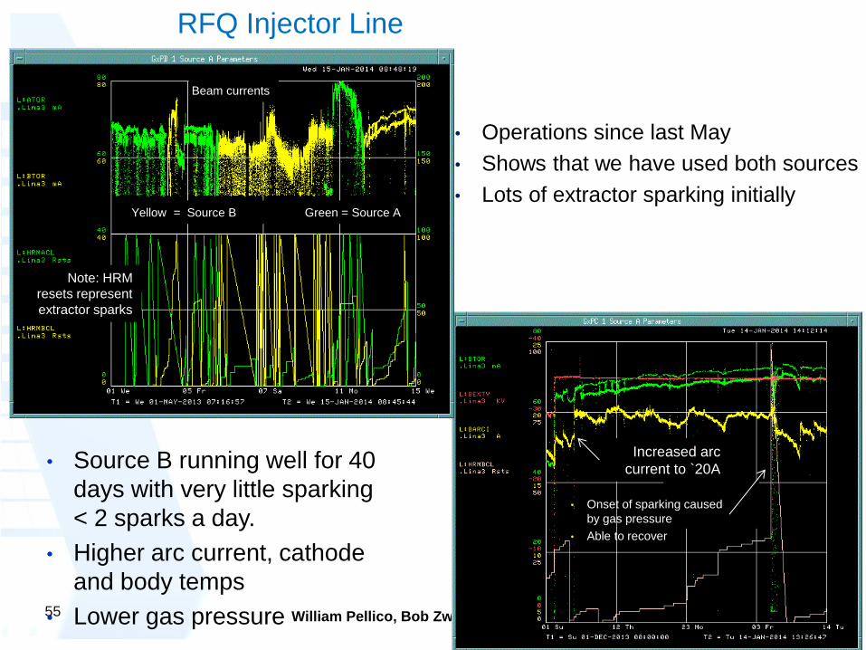
Increased arc
current to `20A
• Onset of sparking caused
by gas pressure
• Able to recover
• Source B running well for 40
days with very little sparking
< 2 sparks a day.
• Higher arc current, cathode
and body temps
• Lower gas pressure
• Operations since last May
• Shows that we have used both sources
• Lots of extractor sparking initially
Note: HRM
resets represent
extractor sparks
Yellow = Source B Green = Source A
Beam currents
RFQ Injector Line
55
William Pellico, Bob Zwaska, Feb 4, 2014
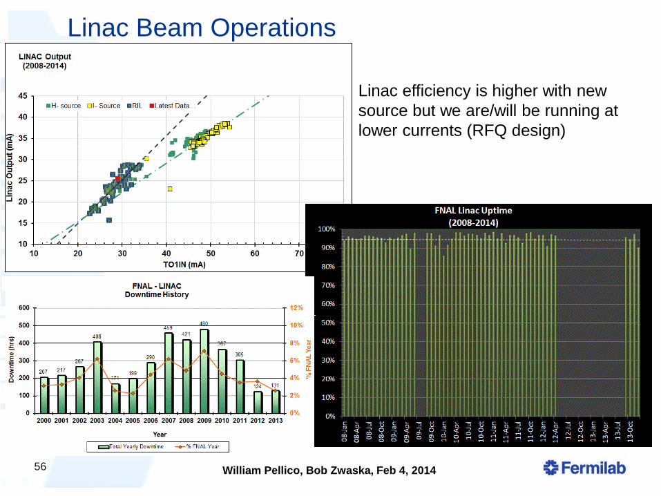
Linac Beam Operations
56
Linac efficiency is higher with new
source but we are/will be running at
lower currents (RFQ design)
William Pellico, Bob Zwaska, Feb 4, 2014
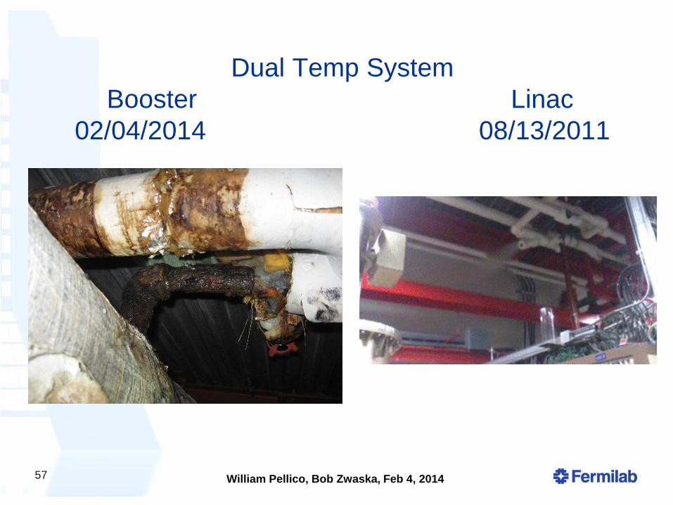
Dual Temp System
Booster Linac
02/04/2014 08/13/2011
57