protective relay travelling wave fault location
TRANSCRIPT
energize - January 2016 - Page 26
TRANSMISSION AND DISTRIBUTION
Cases involving transmission lines spanning rivers or large valleys mean that a small error in fault location can force maintenance crews to spend added hours, or days, to find broken insulators or other faulted line components. Travelling wave fault location overcomes the issue of measuring dis tance us ing h igh-f requency faul t transients measured from a single line end or both line ends. The complications that have to be overcome include connections to protect current transformers and voltage transformers, filters on incoming circuits to avoid surges and spikes, and processing both power system frequencies (1 Hz to 3 kHz) and travelling wave transient
frequencies (10 kHz to 600 kHz) all in the same device.
This paper discusses the implementation and application aspects of travell ing wave fault location in protective relays. Performance limitations are discussed, as well as system requirements and practical installation considerations.
A complete travelling wave fault location sys tem includes more than jus t the detection of the travelling wave itself. The practical aspect of adding this capability without mult iply ing ent i re measur ing systems means it needs to be combined with existing devices.
The basic process of a travelling wave fault location system involves detecting the wave peak, tagging the time of arrival, and comparing it with the time of arrival at the remote end of the line. Of course, each of these steps has its own complications and issues which must be addressed in order to achieve the accuracy promised by today’s high-accuracy timing available at any location in the world.
Input signal selection
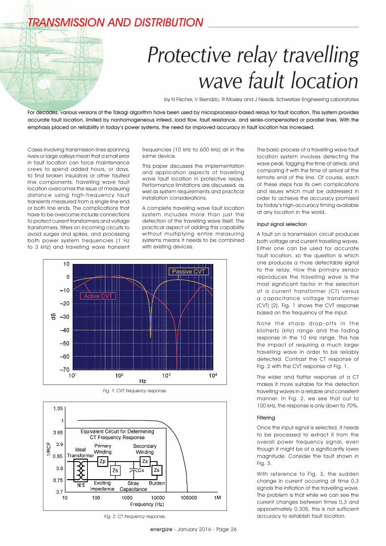
A fault on a transmission circuit produces both voltage and current travelling waves. Either one can be used for accurate fault location, so the question is which one produces a more detectable signal to the relay. How the primar y sensor reproduces the travell ing wave is the most significant factor in the selection of a cur rent t ransformer (CT) versus a capaci tance vol tage t ransformer (CVT) [2]. Fig. 1 shows the CVT response based on the frequency of the input.
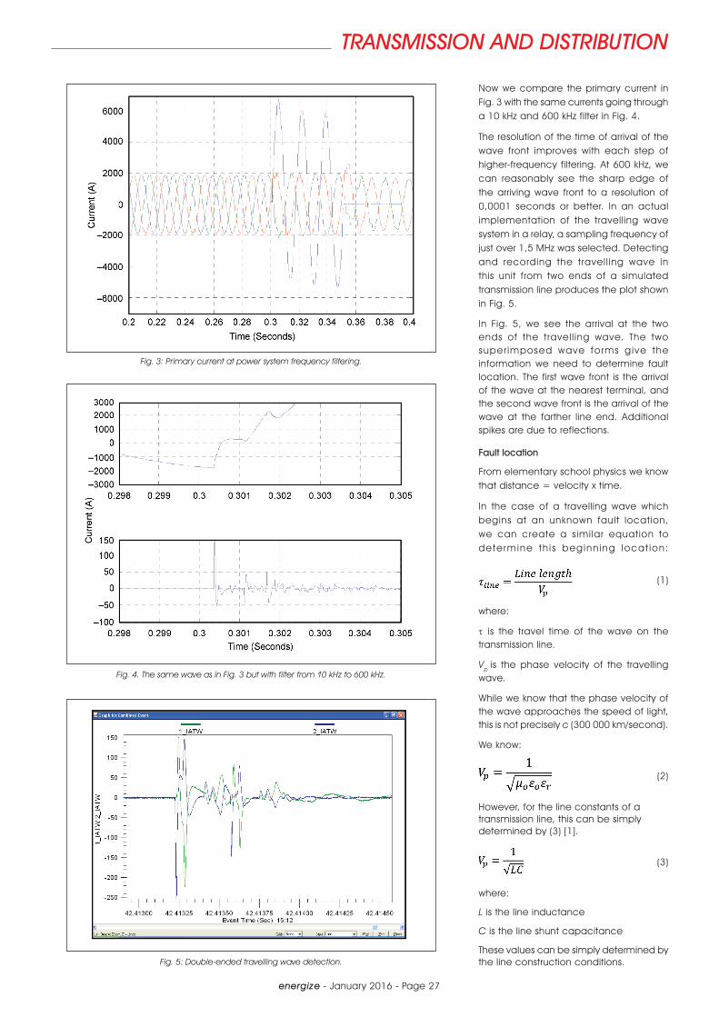
N o t e t h e s h a r p d r o p - o f f s i n t h e k i lohertz (kHz) range and the fading response in the 10 kHz range. This has the impact of requiring a much larger travelling wave in order to be reliably detected. Contrast the CT response of Fig. 2 with the CVT response of Fig. 1.
The wider and flatter response of a CT makes it more suitable for the detection travelling waves in a reliable and consistent manner. In Fig. 2, we see that out to 100 kHz, the response is only down to 70%.
Filtering
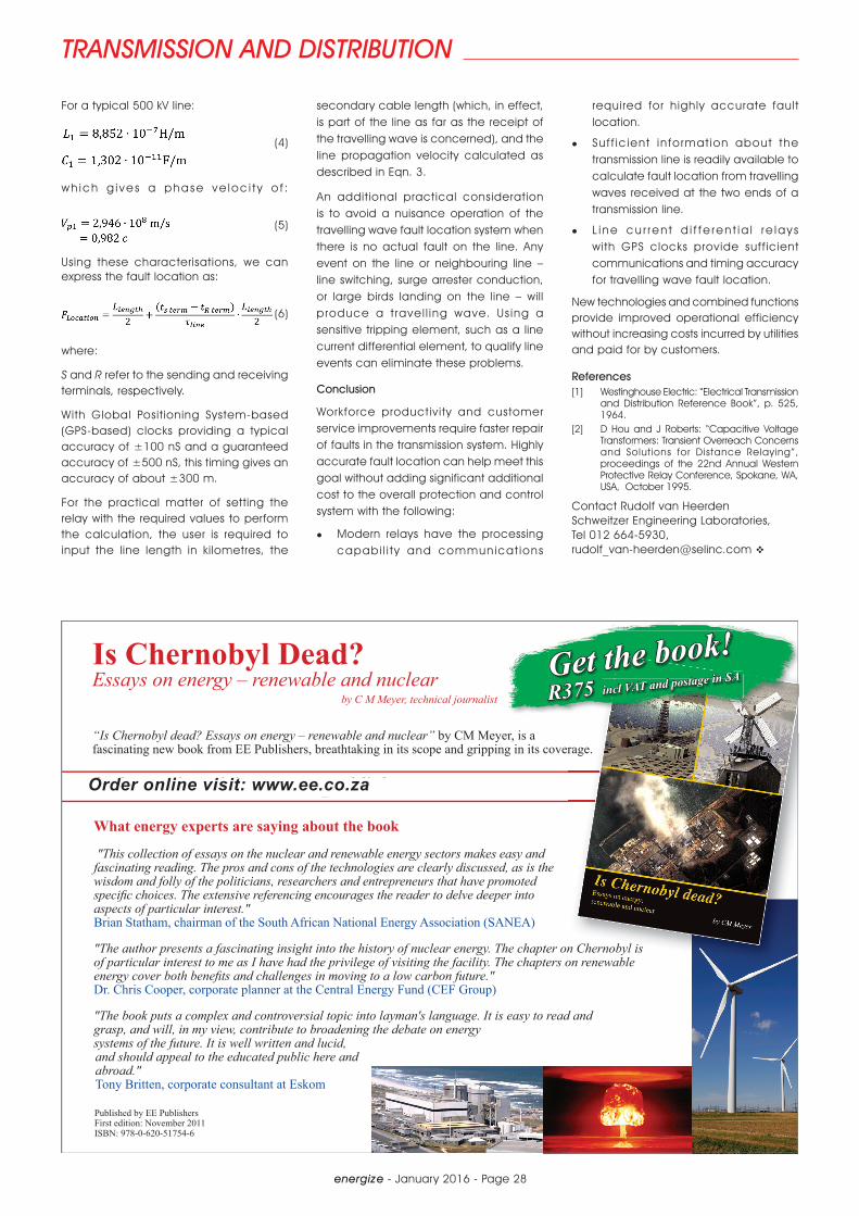
Once the input signal is selected, it needs to be processed to extract it from the overall power frequency signal, even though it might be of a significantly lower magnitude. Consider the fault shown in Fig. 3.
With reference to Fig. 3, the sudden change in current occurring at time 0,3 signals the initiation of the travelling wave. The problem is that while we can see the current changes between times 0,3 and approximately 0,305, this is not sufficient accuracy to establish fault location.
Protective relay travelling wave fault location
by N Fischer, V Skendzic, R Moxley and J Needs, Schweitzer Engineering Laboratories
For decades, various versions of the Takagi algorithm have been used by microprocessor-based relays for fault location. This system provides accurate fault location, limited by nonhomogeneous infeed, load flow, fault resistance, and series-compensated or parallel lines. With the emphasis placed on reliability in today’s power systems, the need for improved accuracy in fault location has increased.
Fig. 1: CVT frequency response.
Fig. 2: CT frequency response.
energize - January 2016 - Page 27
TRANSMISSION AND DISTRIBUTION
Now we compare the primary current in Fig. 3 with the same currents going through a 10 kHz and 600 kHz filter in Fig. 4.
The resolution of the time of arrival of the wave front improves with each step of higher-frequency filtering. At 600 kHz, we can reasonably see the sharp edge of the arriving wave front to a resolution of 0,0001 seconds or better. In an actual implementation of the travelling wave system in a relay, a sampling frequency of just over 1,5 MHz was selected. Detecting and recording the travell ing wave in this unit from two ends of a simulated transmission line produces the plot shown in Fig. 5.
In Fig. 5, we see the arrival at the two ends of the travell ing wave. The two super imposed wave forms g ive the information we need to determine fault location. The first wave front is the arrival of the wave at the nearest terminal, and the second wave front is the arrival of the wave at the farther line end. Additional spikes are due to reflections.
Fault location
From elementary school physics we know that distance = velocity x time.
In the case of a travelling wave which begins at an unknown fault location, we can create a similar equation to dete rmine th i s beginn ing locat ion:
(1)
where:
τ is the travel time of the wave on the transmission line.
Vp is the phase velocity of the travelling wave.
While we know that the phase velocity of the wave approaches the speed of light, this is not precisely c (300 000 km/second).
We know:
(2)
However, for the line constants of a transmission line, this can be simply determined by (3) [1].
(3)
where:
L is the line inductance
C is the line shunt capacitance
These values can be simply determined by the line construction conditions.
Fig. 3: Primary current at power system frequency filtering.
Fig. 4. The same wave as in Fig. 3 but with filter from 10 kHz to 600 kHz.
Fig. 5: Double-ended travelling wave detection.
energize - January 2016 - Page 28
TRANSMISSION AND DISTRIBUTION
For a typical 500 kV line:
(4)
wh ich g i ve s a phase ve loc i t y o f :
(5)
Using these characterisations, we can express the fault location as:
(6)
where:
S and R refer to the sending and receiving terminals, respectively.
With Global Posit ioning System-based (GPS-based) clocks providing a typical accuracy of ±100 nS and a guaranteed accuracy of ±500 nS, this timing gives an accuracy of about ±300 m.
For the practical matter of setting the relay with the required values to perform the calculation, the user is required to input the line length in kilometres, the
secondary cable length (which, in effect, is part of the line as far as the receipt of the travelling wave is concerned), and the line propagation velocity calculated as described in Eqn. 3.
An additional practical consideration is to avoid a nuisance operation of the travelling wave fault location system when there is no actual fault on the line. Any event on the line or neighbouring line – line switching, surge arrester conduction, or large birds landing on the line – will produce a t ravel l ing wave. Us ing a sensitive tripping element, such as a line current differential element, to qualify line events can eliminate these problems.
Conclusion
Workforce productivity and customer service improvements require faster repair of faults in the transmission system. Highly accurate fault location can help meet this goal without adding significant additional cost to the overall protection and control system with the following:
l Modern relays have the processing capabi l i t y and communicat ions
required for highly accurate fault location.
l Suf f ic ient in format ion about the transmission line is readily available to calculate fault location from travelling waves received at the two ends of a transmission line.
l L i ne cu r r en t d i f f e ren t i a l r e lay s with GPS clocks provide suff icient communications and timing accuracy for travelling wave fault location.
New technologies and combined functions provide improved operational efficiency without increasing costs incurred by utilities and paid for by customers.
References[1] Westinghouse Electric: “Electrical Transmission
and Distribution Reference Book”, p. 525, 1964.
[2] D Hou and J Roberts: “Capacitive Voltage Transformers: Transient Overreach Concerns and Solutions for Distance Relaying”, proceedings of the 22nd Annual Western Protective Relay Conference, Spokane, WA, USA, October 1995.
Contact Rudolf van Heerden Schweitzer Engineering Laboratories, Tel 012 664-5930, [email protected] v
Is Chernobyl Dead? Essays on energy – renewable and nuclear
by C M Meyer, technical journalist
What energy experts are saying about the book
"This collection of essays on the nuclear and renewable energy sectors makes easy and fascinating reading. The pros and cons of the technologies are clearly discussed, as is the wisdom and folly of the politicians, researchers and entrepreneurs that have promoted speci c choices. The extensive referencing encourages the reader to delve deeper into aspects of particular interest." Brian Statham, chairman of the South African National Energy Association (SANEA)
"The author presents a fascinating insight into the history of nuclear energy. The chapter on Chernobyl is of particular interest to me as I have had the privilege of visiting the facility. The chapters on renewable energy cover both bene ts and challenges in moving to a low carbon future." Dr. Chris Cooper, corporate planner at the Central Energy Fund (CEF Group)
"The book puts a complex and controversial topic into layman's language. It is easy to read and grasp, and will, in my view, contribute to broadening the debate on energy systems of the future. It is well written and lucid, and should appeal to the educated public here and abroad." Tony Britten, corporate consultant at Eskom
“Is Chernobyl dead? Essays on energy – renewable and nuclear” by CM Meyer, is a fascinating new book from EE Publishers, breathtaking in its scope and gripping in its coverage.
Published by EE Publishers First edition: November 2011ISBN: 978-0-620-51754-6
i
Get the book!R375
Order online visit: www.eepublishers.co.za
incl VAT and postage in SA
Order online visit: www.ee.co.za