proposed seawater reverse osmosis desalination plant · pdf file1 befesa desalination...
TRANSCRIPT
1
Befesa Desalination Developments Ghana Limited
ENVIRONMENTAL IMPACT STATEMENT
ON
PROPOSED SEAWATER REVERSE
OSMOSIS DESALINATION PLANT
AT NUNGUA, ACCRA
March 2011
2
Executive Summary
The management of Befesa Desalination Developments Ghana herein after called Befesa Ghana
acknowledging the immense need for potable water in the city of Accra, especially in the Teshie-
Nungua area, has acquired a parcel of land at Nungua in the Kpeshie sub-district. The site
covering a total area of 6.1 acres has been earmarked for the development of an ultra modern
seawater reverse osmosis (SWRO) desalination plant. The project hopes to produce 60,000 m3/
day (13.2 million gallons a day) bulk potable water for sale to Ghana Water Company Limited
for onward distribution to communities in and around the Teshie-Nungua area of Accra.
The plant will have the following major facilities developed on the plot:
� Desalination Plant
� Product pipes
� Intake and Outfall pipes, and
� Parking lot.
The objectives of the proposed project is to provide sustainable quality of bulk potable water
supply for sale to the Ghana Water Company Limited (GWCL) through distribution to residents,
visitors and businesses located in the Teshie-Nungua catchment of Accra.
The preparation and submission of the Environmental Impact Assessment Report to
Environmental Protection Agency (EPA) in Ghana forms part of the requirements for an
Environmental Permit for the proposed project, in accordance with the requirements in EPA Act,
(Act 490) and the Environmental Assessment Regulations, 1999 (LI 1652). This legislation
requires the company to undertake environmental impact assessment of the proposed seawater
reverse osmosis (SWRO) desalination plant for Befesa Ghana.
In preparing this assessment, the methodology employed included:
� Discussions with project management;
� Field visits by experts and stakeholders to acquaint with project environment; and to
collect baseline data on flora, fauna, hydro-geological, socio-economic and cultural values
in area;
� On-site and laboratory analyses of samples;
3
� Mobilization of information from varied sources;
� Consultations with stakeholders including Ghana Water Company Limited (GWCL),
Accra Metropolitan Assembly, Electricity Corporation of Ghana (ECG), Ghana Standards
Board (GSB) and Ghana National Fire Service (GNFS);
� Assessment of current environmental management practices of the plant;
� Assessment of environmental change that is likely to result from the project;
� Preparation and submission of draft Environmental Impact Assessment Report (EIA); and
� Preparation and submission of final EIA Report after review by EPA.
The project site covers an area of 6.1 acres and is situated at the beachfront, 400 m west of the
Nungua fish landing site. The site is bordered on the north by Nungua Township, south by the
sea, west by undeveloped land, and the east by a residential building.
This report provides site-specific data that forms the initial basis for examining potential impacts
from constructing (mainly laying pipes), operating and decommissioning of proposed
desalination plant. Specifically, it provides the background for determining if construction and/or
post-construction operations including emergency situations could have persistent, non-localised
positive or adverse impacts to the environment. Considering the nature of the environment of the
project, the range of baseline data and information included, but not limited to the following
areas: water quality, geotechnical, oceanographic, socio-economic, and biophysical.
The proposed SWRO desalination plant will provide bulk potable drinking water that will be
piped to GWCL connection point and reservoirs for onward distribution for communities in and
around Nungua and Teshie. This will provide essential water to support the daily livelihoods of
residents as well as industries in the Kpeshie district. The main waste product from the process,
brine, will be released, at the same temperature as the input seawater, far offshore through
diffusers into the sea. Overall, the project will be very beneficial to the economy, health and
livelihood of the people of Kpeshie district. The various components of the project will not have
any adverse effects on the offshore marine environment including its fauna and flora. However,
this report has suggested a number of relevant mitigation options for addressing all perceived
environmental concerns and there are strong indications that this project would be monumental.
Thus, it should be given the required environmental permit and all other needed support.
4
SUMMARY
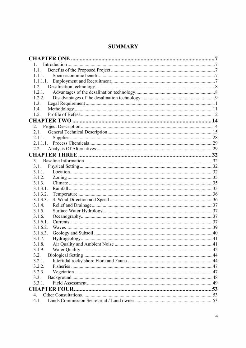
CHAPTER ONE ................................................................................................... 7
1. Introduction .......................................................................................................................... 7
1.1. Benefits of the Proposed Project ...................................................................................... 7
1.1.1. Socio-economic benefit ................................................................................................ 7
1.1.1.1. Employment and Recruitment ...................................................................................... 7
1.2. Desalination technology ................................................................................................... 8
1.2.1. Advantages of the desalination technology .................................................................. 8
1.2.2. Disadvantages of the desalination technology ............................................................. 9
1.3. Legal Requirement ......................................................................................................... 11
1.4. Methodology .................................................................................................................. 11
1.5. Profile of Befesa ............................................................................................................. 12
CHAPTER TWO ................................................................................................ 14
2. Project Description ............................................................................................................. 14
2.1. General Technical Description ....................................................................................... 15
2.1.1. Supplies ...................................................................................................................... 28
2.1.1.1. Process Chemicals ...................................................................................................... 29
2.2. Analysis Of Alternatives ................................................................................................ 29
CHAPTER THREE ............................................................................................ 32
3. Baseline Information .......................................................................................................... 32
3.1. Physical Setting .............................................................................................................. 32
3.1.1. Location ...................................................................................................................... 32
3.1.2. Zoning ........................................................................................................................ 35
3.1.3. Climate ....................................................................................................................... 35
3.1.3.1. Rainfall ....................................................................................................................... 35
3.1.3.2. Temperature ............................................................................................................... 36
3.1.3.3. 3. Wind Direction and Speed ..................................................................................... 36
3.1.4. Relief and Drainage .................................................................................................... 37
3.1.5. Surface Water Hydrology ........................................................................................... 37
3.1.6. Oceanography ............................................................................................................. 37
3.1.6.1. Currents ...................................................................................................................... 37
3.1.6.2. Waves ......................................................................................................................... 39
3.1.6.3. Geology and Subsoil .................................................................................................. 40
3.1.7. Hydrogeology ............................................................................................................. 41
3.1.8. Air Quality and Ambient Noise ................................................................................. 41
3.1.9. Water Quality ............................................................................................................. 42
3.2. Biological Setting ........................................................................................................... 44
3.2.1. Intertidal rocky shore Flora and Fauna ...................................................................... 44
3.2.2. Fisheries ..................................................................................................................... 47
3.2.3. Vegetation .................................................................................................................. 47
3.3. Background .................................................................................................................... 48
3.3.1. Field Assessment ........................................................................................................ 49
CHAPTER FOUR ............................................................................................... 53
4. Other Consultations ............................................................................................................ 53
4.1. Lands Commission Secretariat / Land owner ................................................................ 53
5
4.2. Accra Metropolitan Assembly ....................................................................................... 53
4.3. Environmental Protection Agency (EPA) ...................................................................... 53
4.4. Electricity Company of Ghana (ECG) ........................................................................... 54
4.5. Ghana Water Company Limited (GWCL) ..................................................................... 54
4.6. Public Utilities Regulatory Commission (PURC) .......................................................... 54
4.7. Ghana Telecom .............................................................................................................. 54
4.8. Ghana National Fire Service (GNFS) ............................................................................ 54
4.9. Ghana Standards Board (GSB) ...................................................................................... 55
CHAPTER FIVE ................................................................................................ 56
5. Identification of Potential Environmental Impacts ............................................................ 56
5.1. Impact identification ...................................................................................................... 56
5.2. Construction Phase ......................................................................................................... 57
5.2.1. Air quality, Noise and Vibration ................................................................................ 57
5.2.2. Drainage and erosion .................................................................................................. 57
5.2.3. Solid waste ................................................................................................................. 57
5.2.4. Health and safety ........................................................................................................ 58
5.2.5. Security and safety ..................................................................................................... 58
5.2.6. Employment and income ............................................................................................ 58
5.3. Operational Phase Impacts ............................................................................................. 58
5.3.1. Noise ........................................................................................................................... 58
5.3.2. Sewage ....................................................................................................................... 59
5.3.3. Security and Safety ..................................................................................................... 59
5.3.4. Employment ............................................................................................................... 59
5.3.5. Air Quality .................................................................................................................. 59
5.3.6. Drainage and erosion .................................................................................................. 59
5.3.7. Potential Impacts on Local Government and Regional Benefits ............................... 60
5.3.8. Potential Impacts on Intertidal Beach Users .............................................................. 60
CHAPTER SIX ................................................................................................... 61
6. Mitigation of Significant Impacts ...................................................................................... 61
6.1. Constructional phase impacts ......................................................................................... 61
6.1.1. Noise and vibration .................................................................................................... 61
6.1.2. Drainage and erosion .................................................................................................. 61
6.1.3. Solid waste ................................................................................................................. 62
6.1.4. Health and safety ........................................................................................................ 62
6.1.5. Visual intrusion .......................................................................................................... 62
6.2. Operational Phase Impacts ............................................................................................. 62
6.2.1. Noise ........................................................................................................................... 62
6.2.2. Air quality .................................................................................................................. 63
6.2.3. Solid waste ................................................................................................................. 63
6.2.4. Sewage ....................................................................................................................... 63
6.2.5. Semi-solid waste ........................................................................................................ 63
6.2.6. Security and Safety ..................................................................................................... 64
CHAPTER SEVEN ............................................................................................. 65
7. Provisional Environmental Management Plan ................................................................... 65
7.1. Monitoring Plan .............................................................................................................. 65
7.2. Conclusions and Recommendations ............................................................................... 66
6
BIBLIOGRAPHY ............................................................................................... 69
APPENDICES ..................................................................................................... 71
1. Site Plan ........................................................................................................ 71
2. Proposed Block Plan of plant ....................................................................... 71
3. Accra Metropolitan Assembly (Zoning Status and ROW clearance) ........ 71
4. Environmental Protection Agency (EPA) ................................................... 71
5. Geotechnical report ...................................................................................... 71
6. Ghana Standards Board (GSB) ................................................................... 71
7. Material Safety Data Sheets (MSDS) .......................................................... 71
8. Profile of Lead Consultants ......................................................................... 71
7
CHAPTER ONE
1. Introduction
The water supply sector and private investment were accorded a priority status in the Economic
Recovery Programme (ERP) initiated in the 1980’s to revitalize the Ghanaian economy that had
then become stagnant or repressive. Since then the Economic Recovery Programme has to a
greater extent arrested the situation. One of the results of the ERP is the influx of direct foreign
investment as well as the awakening of indigenous Ghanaians to participate in emerging positive
economic activities such as the establishment of the proposed desalination plant.
The world's water consumption rate is doubling every 20 years, outpacing the rate of population
growth by two times. It is projected that by the year 2025 water demand will exceed supply by
56%, due to persistent regional droughts, shifting of the population to urban coastal cities, and
water needed for industrial growth. The supply of fresh water is rather on the decrease while
water demand for food, industry and people is on the rise.
Lack of fresh water reduces economic development, which in turn lowers living standards.
Clearly, there is a critical worldwide need to better manage this increasingly valuable resource.
Scarcity of fresh water has serious socioeconomic implications. It can slow or stop economic
expansion, reduce agricultural output, hamper food independence and degrade public health and
quality of life.
1.1. Benefits of the Proposed Project
1.1.1. Socio-economic benefit
The use of desalination overcomes the paradox faced by many coastal communities, which is having access to a practically inexhaustible supply of saline water but having no way to use it
1.1.1.1. Employment and Recruitment
In the construction phase, the project will provide job opportunities for both skilled and unskilled personnel from Teshie-Nungua and
8
its environs. A labour force of about 80 is anticipated during the construction phase. Each direct job should create several local indirect jobs, significantly increasing local employment opportunities.
1.2. Desalination technology
The oceans make up 97% of the world’s volume of water. This vast water reservoir may be
harnessed for domestic fresh water usage employing the state-of-the-art technology such as
desalination. Desalination is a separation process used to reduce the dissolved salt content of
saline water to a usable level. The desalination technology is suitable in regions where seawater
is readily available. The technology provides reliable freshwater supply at affordable cost using
high energy efficiency with low environmental impacts. In Africa for instance, sea water reverse
osmosis (SWRO) plants can be found in Algeria, Morocco, Egypt and South Africa. The
technology is rather common in the Middle East e.g. Saudi Arabia; the USA, Caribbean islands,
South America and Europe. The proposed desalination plant in Ghana is an important step
towards improving the freshwater needs of the burgeoning populations in the coastal community
of Nungua and its environs within Accra. Further, upon completion, the plant will be the first of
its’ kind in Ghana and in West Africa.
1.2.1. Advantages of the desalination technology
• The processing system is simple; the only complicating factor is finding or producing a
clean supply of feed water to minimize the need for frequent cleaning of the membrane.
• Systems may be assembled from prepackaged modules to produce a supply of product
water ranging from a few litres per day to 750 000 l/day for brackish water, and to 400
000 l/day for seawater; the modular system allows for high mobility, making reverse
osmosis (RO) plants ideal for emergency water supply use.
• Installation costs are low.
• The technology has a very high space/production capacity ratio, ranging from 25 000 to
60 000 l/day/m2.
• Low maintenance, nonmetallic materials are used in construction lowering the
environmental impacts.
9
• Energy use to process brackish water ranges from 1 to 3 kWh/m3 of product water; and
from 2.5 - 4.5 kWh/m3 for seawater, depending on selected technology and raw-water
conditions.
• The technology can make use of an almost unlimited and reliable water source, the sea.
• The technology can be used to remove organic and inorganic contaminants.
• Aside from the need to dispose of the brine, reverse osmosis (RO) has a negligible
environmental impact.
• It makes minimal use of chemicals which disposal may be unwieldy.
• Project will contribute to improvement in the technological know-how on desalination in
Ghana.
1.2.2. Disadvantages of the desalination technology
• The membranes may be sensitive to failure by polluted seawater and inappropriate
handling by workers.
• The feed water usually needs to be pretreated to remove particulates, organic matter,
micro-organism and other pollutants (in order to prolong membrane life).
• There may be short interruptions of service during stormy weather (which may increase
particulate re-suspension and the amount of suspended solids in the feed water) for plants
that use seawater, depending on the robustness of the pretreatment
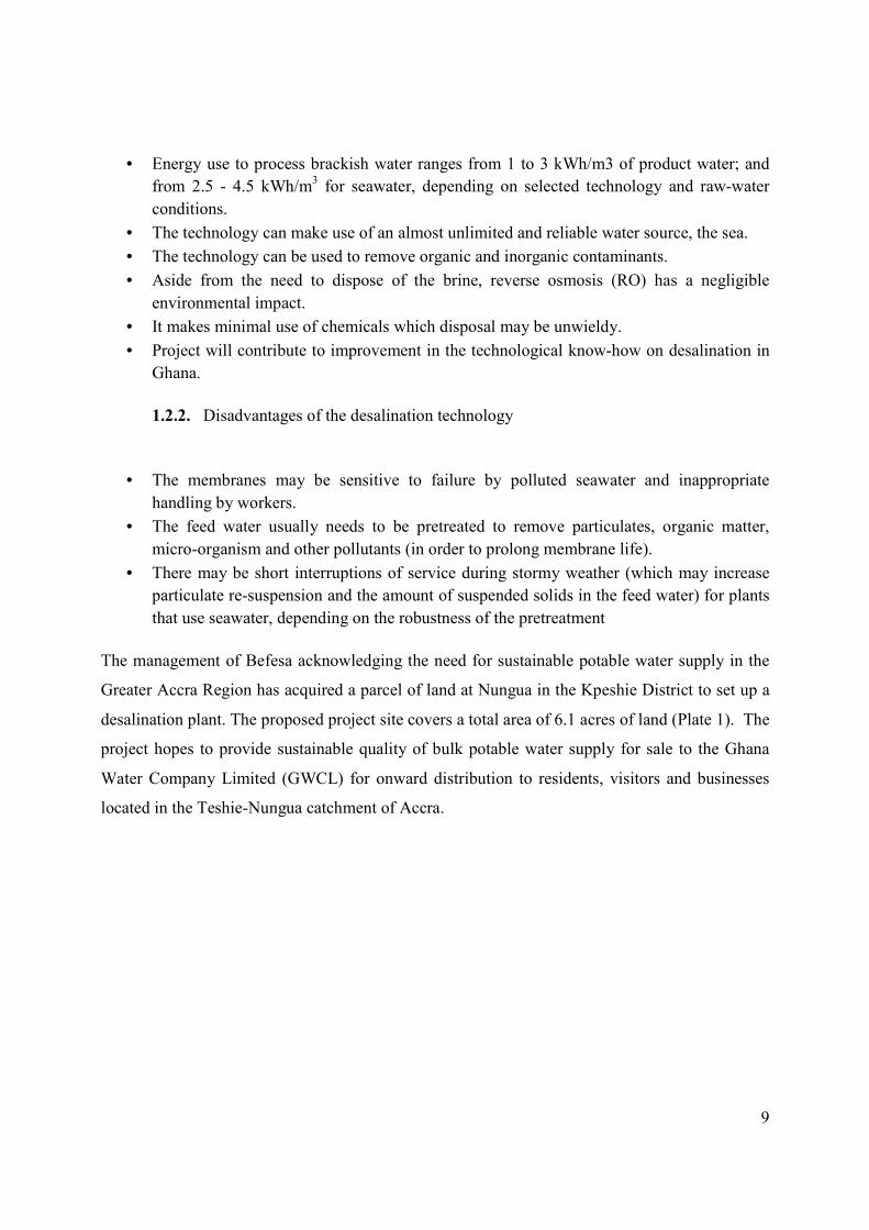
The management of Befesa acknowledging the need for sustainable potable water supply in the
Greater Accra Region has acquired a parcel of land at Nungua in the Kpeshie District to set up a
desalination plant. The proposed project site covers a total area of 6.1 acres of land (Plate 1). The
project hopes to provide sustainable quality of bulk potable water supply for sale to the Ghana
Water Company Limited (GWCL) for onward distribution to residents, visitors and businesses
located in the Teshie-Nungua catchment of Accra.
10
Plate 1 Landward portion of the proposed project site at Nungua, Accra. (March 2011)
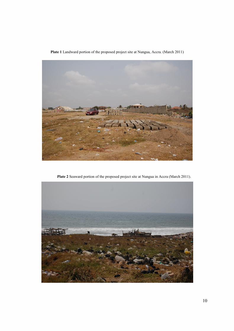
Plate 2 Seaward portion of the proposed project site at Nungua in Accra (March 2011).
11
1.3. Legal Requirement
The preparation and submission of the Environmental Report to the EPA of Ghana forms part of
the requirements for an Environmental Permit for the proposed project, in accordance with the
requirements in Ghana EPA Act, (Act 490) and the Environmental Assessment Regulations, 1999
(LI 1652).
1.4. Methodology
To facilitate the permitting process, proponents are required to provide adequate information on
their proposal to serve as a basis for decision-making. It is in fulfillment of this requirement that
this Report has been prepared by Befesa Desalination Developments Ghana, hereinafter called
Befesa Ghana, for the design, construction, testing and commissioning of a SWRO desalination
plant, and all associated works at Nungua in Accra. To facilitate this, site inspections,
consultations, visual assessments and evaluation procedures were undertaken.
The study team visited the project site and subsequently carried out in-depth assessment of the
likely environmental implications of the proposed desalination plant development. The team also
interacted and discussed possible environmental and socio-economic impacts of the proposed
project with a number of stakeholders in order to:
� Identify key environmental concerns relating to the proposed desalination project; and
� Highlight the concerns of the relevant stakeholders in the preparation of the Report.
The general views and consensus arrived at during the consultation are summarized as follows:
� Constructional phases impacts include:
(i) Noise generation,
(ii) Traffic generation,
(iii) Occupational hazards, and
12
� Operational phase impacts comprise the following:
(i) Handling and treatment of sewerage and its disposal,
(ii) Drainage systems,
(iii) Vehicular traffic and pedestrian conflict,
(iv) Impacts from other planned developments in the area,
(v) Management and disposal of brine, and
(vi) Management of noise nuisance.
The main areas of concern addressed in the Report cover the Construction and Operation phases,
where pragmatic measures would be outlined to mitigate the effects of noise, dust generation,
movement of heavy vehicles and equipment, visual intrusion, occupational hazards, and disposal
of debris. Operational impacts include accidental fire outbreaks, solid and liquid waste
generation, management of product waste in the form of brine, occupational health and safety,
vehicular traffic generation, and noise will also be addressed.
1.5. Profile of Befesa
Befesa is a limited liability company headquartered in Seville, Spain and incorporated on 5th
October 1990. It has presence in 23 countries including Spain, the Netherlands, Morocco, Algeria,
Angola, India, China, Sri Lanka, Ecuador, Nicaragua, Peru and Tunisia. A branch office is currently
established in Accra. Befesa is an environmental engineering company that designs, builds, and
operates waste treatment plants, and hydroelectric power stations, hydraulics and irrigation, waste
water treatment and reuse, and produces bulk potable drinking water from either seawater or
brackish water using the reverse osmosis (RO) desalination process. The bulk potable water will
be sold to the Ghana Water Company Ltd. who will intend distribute for public consumption. At
present, the total installed capacity of desalinated water amounts to more than 700,000 m3/d and once
all the desalination plants under construction are finished it will rise up to more than 1,200,000 m3/d.
In fact, nowadays, Befesa is among the major international players and offers one of the largest
reference lists in the desalination market worldwide.

13
Befesa has been part of its mother company, Abengoa S. A., for 67 years. The company is
currently headed by Mr. Carlos Cosín Fernández with Mss. Inmaculada Paños Casteleiroz
responsible for environmental matters. The core workforce of Befesa consists of staff working
under Directors in various directorates, most of which are either technical or administrative.
Additionally, casual staff such as security and labourers would be employed as and when needed.
14
CHAPTER TWO
2. Project Description
Befesa Ghana plans to establish a 60,000 m3/day seawater reverse osmosis (SWRO) desalination
plant to produce constant fresh drinking water supply at Nungua, in Accra. Using a technology
that tenders economical solutions even in rural areas, desalination plants can be installed close to
end-users. Decentralised solutions reduce distribution cost, minimize environmental damage,
enable water intake from saltwater wells and are easily adapted to suit local building traditions.
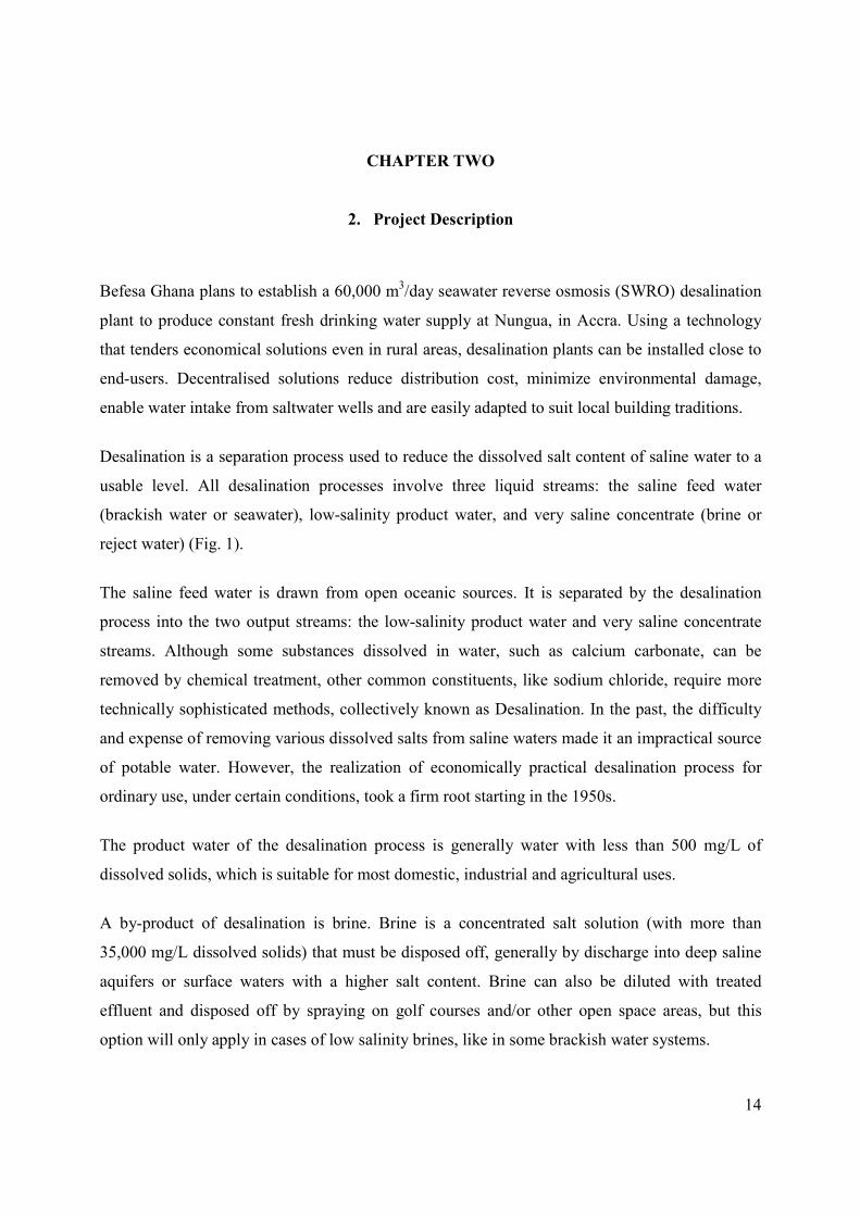
Desalination is a separation process used to reduce the dissolved salt content of saline water to a
usable level. All desalination processes involve three liquid streams: the saline feed water
(brackish water or seawater), low-salinity product water, and very saline concentrate (brine or
reject water) (Fig. 1).
The saline feed water is drawn from open oceanic sources. It is separated by the desalination
process into the two output streams: the low-salinity product water and very saline concentrate
streams. Although some substances dissolved in water, such as calcium carbonate, can be
removed by chemical treatment, other common constituents, like sodium chloride, require more
technically sophisticated methods, collectively known as Desalination. In the past, the difficulty
and expense of removing various dissolved salts from saline waters made it an impractical source
of potable water. However, the realization of economically practical desalination process for
ordinary use, under certain conditions, took a firm root starting in the 1950s.
The product water of the desalination process is generally water with less than 500 mg/L of
dissolved solids, which is suitable for most domestic, industrial and agricultural uses.
A by-product of desalination is brine. Brine is a concentrated salt solution (with more than
35,000 mg/L dissolved solids) that must be disposed off, generally by discharge into deep saline
aquifers or surface waters with a higher salt content. Brine can also be diluted with treated
effluent and disposed off by spraying on golf courses and/or other open space areas, but this
option will only apply in cases of low salinity brines, like in some brackish water systems.
15
Figure 1: Components and Elements of a typical Reverse Osmosis Desalination Process.
Befesa’s desalination process uses membrane systems based on the RO principle. The energy
recovery system recovers the brine energy at the outlet of the membranes. The energy recovery
system will be based on pressure exchangers systems. In order to control the flow of water fed to the
membranes, a control valve will be installed at the brine outlet from the energy recovery system.
Counter-pressure will be created with the brine at the energy recovery system outlet in order to
overcome head losses in the collectors to the reject pit
2.1. General Technical Description
Design of the plant has been done for a capacity of 60.000 m3/day. Average raw water flow rate
necessary for production of the 60 MLD Plant is 6100 m3/h.
Raw water is taken directly from the sea and pumped through one 1100 mm diameter pipeline
with a length of 250 m and a coarse filtration system. Feed and brine pipes, will be installed
above a structure built of a groin between the coast line and pk 150 approximately and a
structural jetty (piles and precast beams) up to pk 250.
At the end of the jetty, an intake structure and protection for the pumps will be built. The intake
depth will be decided once detailed marine studies are performed.
16
The reject pipe will have a diffusers system installed at pk 150 and it will be designed to be
protected by the boulders of the groin.
Diameter, material and length of the pipe as well as the marine works design will be reviewed
after studying the sea conditions, soil conditions, plant site, etc.
Open Sea Water Intake
A pumping station will be placed at the intake point. Three pumps (two working and one in
standby) will be placed to pump the water into the pretreatment of the plant. These pumps will
have variable frequency driver to increase the flexibility of the plant. Inlet velocity will be kept
low to avoid disturbance to surrounding marine life.
Desinfection
The raw water will be chlorinated by applying a dose of sodium hypochlorite before automatic
filters. Also, ferric chloride will be injected into a static mixer installed after automatic filters.
Sodium hypochlorite will be dosed with intermittent shock because, based on our experience, it
increases the barrier for bacteria. Also, continuous chlorination leads to unpredicted
precipitations that can affect the ultrafiltration system so we have decided to use shock doses.
Ferric chloride will be dosed in order to eliminate suspended matters and colloids present in the
sea water.
The ferric chloride (coagulant) is injected by a drive and microprocessor control dosing pump. A
total of two dosing pumps (plus one in reserve) are considered. These pumps feature diaphragm
dosing head with integrated vent valve, suction and discharge ball valves. The pumps feature
variable speed motor, a turn down ratio of 1:800 and a complete control interface. Accessories
such as calibration pot, pulsation dampener, isolation and pressure valves, Y strain filter and
pressure gauge will also be included.
GRP tanks for each chemical in an enclosed area will also be included.
17
Pretreatment
After intake, seawater will enter in the ultrafiltration system after passing through automatic
strainers.
These filters act like security filters in order to assure that only raw water with the necessary
conditions enters the UF system.
The pretreated water, before arriving at UF system, will pass through two units plus one in
standby of automatic filters to treat a total flow of 6100 m3/h with a filtration rate of <50 microns.
The back wash flow will go to a reject pit.
Ultra filtration system
Ultra filtration is a pressure-driven membrane separation process that helps removes particulate
matter from aqueous solutions such as water. UF membrane typically have pore sizes in the range
of 0,01 to 0,1 µm and efficiently remove bacteria and most viruses, colloids and silt. The smaller
the nominal pore size, the higher the removal efficiency. Most materials that are used in ultra
filtration are polymeric and are naturally hydrophobic, such as polysulfone (PS),
polyethersulfone (PES), polypropylene (PP) or polyvinylidenefluoride (PVDF)
Proposed system is composed of a total of 15 skids. Supplier will be Norit or similar. If another
supplier is finally chosen, design of the plant and number of skids must be adapted.
During filtration, raw water is driven under pressure through the pores of the ultra filtration
membranes. The intake pumps discharge into headers that connect each module. The pressurized
feed water enters the modules and contacts the surface of the individual hollow fibre membranes.
The feed flow passes through the wall of the fibres. Filtered water (permeate) exits each module
through the permeate manifold.
Typically system is operated at a constant permeate flow. The transmembrane pressure will
naturally increase over the time, and the modules can be cleaned by mechanical cleaning to
remove the fouling layer for longer service life. Mechanical cleaning occurs automatically during
18
the filtration process to remove contaminants that have accumulated on the membrane surface
and maintain the filtration flow rate. This sequence can use water or
a combination of air and water. Water is supplied from a filtrated water storage tank. Filtrated
water is pumped through the module in the reverse direction and is collected or diverted to a
drain for disposal.
To further restore the performance of ultra filtration membranes and control biofouling, a
chemical cleaning process can be used. The frequency of this will depend on the fouling nature of
the feed water. This chemical cleaning can be divided in short term and long term cleaning.
As a supplement to the short term chemical cleaning, ultra filtration membranes may require
additional chemical cleaning referred to as a clean-in-place (CIP). CIP is used to restore the
membrane performance to a clean TMP condition. A variety of chemicals (mainly acid and
caustic steps) can be used to dissolve or dislodge specific contaminants or reversible fouling not
removed during previous sequences.
Plant will be composed of operating skids plus stand-by/back-up skid. This stand-by skid/back-
up will maintain relaxed fluxes during cleaning or CIP sequences and will be able to maintain
total production in the event of a skid break down.
In order to control all operation sequences and advise about deviations form projected values the
following will be measured on each skid:
- Feed pressure
- Filtrate pressure
- Skid differential pressure
- Filtrate flow
Also common filtrate turbidity will be considered.
RO process
Intermediate pumping area
19
After ultra filtration, water will enter in the RO building. First, water is stored in one intermediate
tank of 300 m3.
The water will be pumped to the high pressure pumps and pressure exchangers. Pumps will be
centrifugal and horizontal type. A total of 6 pumps will be installed, two plus one in standby to
pump water to the high pressure pumps, and two more plus one in standby to pump water into the
pressure exchangers. Materials for the pumps will be super duplex. Intermediate pumps to HPP
will be equipped with variable frequency drivers.
A retaining valve, a pneumatic butterfly valve with positioner, along with pressure and
temperature devices will be installed at each motor-pump set. The pumps discharge into two GRP
pipes, one of 700 mm and the other of 800 mm with required pressure rating. Final design will be
confirmed in the detailed engineering phase.
Chemical dosing
1. Sodium metabisulphite dosing (RO system)
This product is added to eliminate residual chlorine in the filtrate water in order to prevent it from
entering the membranes.
The product is added before the RO system by two drive and microprocessor control dosing
pumps (plus one in reserve). These pumps feature diaphragm dosing head with integrated vent
valve, suction and discharge ball valves. The pumps feature variable speed motor, a turn down
ratio of 1:800 and a complete control interface.
Accessories such as calibration pot, pulsation dampener, isolation and pressure valves, Y strain
filter and pressure gauge will also be included.
GRP tanks in an enclosed area will also be included.
2. Anti-scalant dosing (R.O. system)
20
Since sea water is concentrated in the membranes, in order to prevent the precipitation of ferric
hydroxide and calcium fluoride, calcium sulphate and strontium sulphate salts, an anti-scalant
agent will be metered to prevent the formation of crystalline networks, by maintaining the ions
dispersed and enabling the limit of the product of solubility of these salts to be exceeded.
The product is added before the RO system by two drive and microprocessor control dosing
pumps (plus one in reserve). These pumps feature diaphragm dosing head with integrated vent
valve, suction and discharge ball valves. The pumps feature variable speed motor, a turn down
ratio of 1:800 and a complete control interface.
Accessories such as calibration pot, pulsation dampener, isolation and pressure valves, Y strain
filter and pressure gauge will also be included. The product injection pipes are made of PVC.
GRP tanks in an enclosed area will also be included.
3. Sulphuric acid dosing for UF
Sulphuric acid is added for CEB ultra filtration system.
A sulphuric acid dosing system will be installed, equipped with a level meter, switches, alarms,
drainage and other accessories. The product is added by one drive and microprocessor control
dosing pumps (plus one in reserve). These pumps feature diaphragm dosing head with integrated
vent valve, suction and discharge ball valves. The pumps feature variable speed motor, a turn
down ratio of 1:800 and a complete control interface.
Accessories such as calibration pot, pulsation dampener, isolation and pressure valves, Y strain
filter and pressure gauge will also be included. The product injection pipes and accessories will
be made of PVDF.
CS bulk tank in an enclosed area will also be included.
4. Sodium hypochlorite dosing for UF
Sodium hypochlorite is added for CEB ultra filtration system.
21
The product is added by one drive and microprocessor control dosing pumps (plus one in
reserve). These pumps feature diaphragm dosing head with integrated vent valve, suction and
discharge ball valves. The pumps feature variable speed motor, a turn down ratio of 1:800 and a
complete control interface.
Accessories such as calibration pot, pulsation dampener, isolation and pressure valves, Y strain
filter and pressure gauge will also be included.
GRP bulk tank in an enclosed area will also be included.
5. Sodium hydroxide dosing for UF
Sodium hydroxide is added for ultra filtration system CEB for pH adjustment.
The product is added by one drive and microprocessor control dosing pump (plus one in reserve).
These pumps feature diaphragm dosing head with integrated vent valve, suction and discharge
ball valves. The pumps feature variable speed motor, a turn down ratio of 1:800 and a complete
control interface.
Accessories such as calibration pot, pulsation dampener, isolation and pressure valves, Y strain
filter and pressure gauge will also be included.
CS bulk tank in an enclosed area will also be included.
Reverse Osmosis system
High pressure system
In order to reach desired product water quality (<500 ppm) a single pass has been considered
based on feed water quality, range of temperatures and plant recovery rate.
Feed pipes of the pumps are made of GRP. The discharge/outlet pipes of the pumps (high
pressure pipes) are made of super duplex.
22
A low-pressure pressure gauge is placed at the inlet point of each rack; this gauge is fitted with an
alarm, stopping the pump for low aspiration pressure. At the inlet point there is an automatic
valve that can be activated from the panel. An inlet flow meter is provided, with a switch for very
low flow rates levels which triggers the motor pump. Also a pressure gauge is fitted at the
discharge of the pump.
The brine is transferred to the energy recovery system through super duplex pipes.
The bearings of the motor pump include temperature indicators, with a high temperature alarm
and triggering for very high temperatures. Temperature sensors in the motor windings are also
installed.
Booster pumps
The energy recovery system supply part of the feed water to the membranes. A booster pump is
needed to overcome the pressure drop through the membranes and the recovery system. These
recirculation pumps are used to increase this pressure to the membrane input point.
The feed and discharge pipes are made of superduplex materials.
Booster pumps will include VFD. The system provides constant production and also maintains
inlet pressure constant. The design is intended to ensure the most unfavourable operating
scenario, such as the lowest sea water temperature and dirty or fouled membranes. This system
enables operation in other scenarios, such as variable discharge and pressure conditions.
Energy recovery system
As mentioned previously, brine energy is recovered at the outlet of the membranes by the energy
recovery system. The energy recovery system will be based on pressure exchangers systems.
In order to control the flow of water fed to the membranes, a control valve will be installed at the
brine outlet from the energy recovery system.
23
Counter-pressure will be created with the brine at the energy recovery system outlet in order to
overcome head losses in the collectors to the reject pit.
Reverse osmosis trains
The RO system has been designed to produce up to 60.000 m3/day. It will have 4 trains fed by 2
plus one in standby high pressure pumps and 12 energy recovery systems per rack.
- The membranes are able to support the differential pressure that guarantees the seawater
desalination.
- Does not exist contact between the fluids of high pressure (feed water and brine) and the
permeate water
- The active surface by membrane is of 440 squared feet, allowing reducing the cost of the
system.
- Membrane performance parameters are controlled in order to reduce operation costs.
The following instruments are provided for each RO train:
- A high-pressure gauge with alarm.
- Feed/Reject differential pressure.
- Permeate electromagnetic flow-meter.
- Permeate conductivity meter.
Spiral wound membranes will be used. Seven (7) membranes or elements will be placed in each
pressure vessel. The proposed design consists of one pass and one stage. Membrane system
recovery is 45% and plant availability will be approximately 95-96%. Final design will be
confirmed in the detailed engineering phase.
Product water collection pipe is connected to a common pipe that discharges to the product tank.
Low pressure feeding pipes will be GRP, while high pressure piping will be made of super
duplex. Permeate pipes in each rack will be made in AISI 316 or Polypropylene. The general
24
product pipes connected to the product tank will be made of GRP. Victaulic-type joints will be
used for pressure vessels connections.
A differential pressure gauge is placed between the feed water and the discharged water point,
with a high-pressure alarm. The difference in pressure indicates the degree of fouling of the
membranes.
A product sampler will also be installed and placed on a general sampling panel. This panel will
be installed on one side of the corresponding train. On this panel, and using fast connections,
product water conductivity can be sampled.
This fast track approach offers a number of advantages over the traditional process plant design,
manufacture, installation and commissioning:
• Lowers the risk associated with site based erection of process plant.
• Increases confidence in fit for purpose plant.
• Provides flexibility with inter changeable skid packages.
• Offers fast track increases in plant size.
• Provides operational flexibility in skid unit replacement.
• Eliminates dependence on unskilled resources.
• Reduces cost in project execution.
• Eliminates complicated commissioning of plant.
There is substantial benefit with this option during all parts of the project from feasibility study to
operational phase. It also facilitates confidence in the quality assurance of the plant as the process
skids will be manufactured by a Company meeting all international quality assurance and
international specifications. There is potential for substantial reductions in project costs with a
successfully delivered fast track project.
This option also substantially reduces health and safety issues that are common with large
numbers of unskilled site resources. Finally, this option offers the potential to provide process
25
plants pre-manufactured with pre-established designs leading to reductions in cost due to
standardization
Chemical cleaning
One chemical cleaning will be installed. The system will be designed to guarantee the right
cleaning of one single RO rack.
Different chemical products can be used to clean the membranes. The choice of product will
depend on the type of fouling and membranes. The most typical are the followings:
- Citric acid.
- Borax.
- Sodium hydroxide.
- E.D.T.A.
- Formaldehyde.
The cleaning system will consist of the following components:
- GRP tank for dissolving and mixing cleaning chemicals.
- Chemical cleaning pumps
- RO CIP cartridge filter
The dissolved solution enters the RO train after the high pump group. It passes through the
pressure vessels, washing them at low-pressure; consequently, most of the solution is released
through the discharge pipes with the dissolved precipitated particles and the small particles that it
contains which are responsible for fouling the membranes. This discharge or outlet water is once
again transferred to the cleaning tank, thus re-circulating the chemical solution.
A small amount of water is discharged along the permeate pipe; this water returns to the cleaning
tank through a pipe connected to the cleaning circuit.
26
The system will also include the following accessories: stairs for access, superior platform, access
cover, graduated external level and vent.
The membranes must be cleaned regularly in order to ensure their proper conservation, and also
to guarantee the proper functioning of the process.
Flushing system
Whenever there is a prolonged stoppage on one of the reverse osmosis lines, the motor-pumps
and the energy recovery system must be rinsed with desalted water, as well as the osmosis
modules and the high-pressure pipes.
If this rinsing operation is not performed, the above mentioned equipment may suffer serious
corrosion and precipitation in the modules, causing serious damage. The flushing system has the
option to directly take the permeate water from the permeate collector for the flushing of the
water in the RO racks, arranging to such aim, a suitable system of valves.
Flushing is achieved by gravity using permeate taken from the permeate line/tank for each line.
Neutralization and emptying
Once the UF modules have been washed, the washing water will be neutralised, stabilised in the
neutralization tank before being transferred to the reject pit and emptied into the sea by gravity,
mixed with brine.
The washing water from RO modules will be neutralised in the CIP tank before being transferred
to the reject pit.
Re-mineralization system
Permeate from the RO system is to be stabilized with lime and CO2. An average of 40% of the
permeate water previously saturated on CO2. The rest of the permeate water will be by-passed
and mixed downstream in order to reach desired product water parameters. Carbon dioxide will
be used to provide acidity in the water to react with the lime to form calcium bicarbonate.
27
Water corrosivity can be estimated by calculating the difference between actual pH and
hypothetical pH at equilibrium with calcium carbonate. This difference is defined as Langelier
Saturation Index (LSI).
In under-saturated water, represented by a negative LSI, CaCO3 tends to dissolve, whereas in
oversaturated water, represented by a positive LSI, CaCO3 tends to precipitate. Theoretically, in
waters with LSI equal to cero, CaCO3 neither dissolves nor precipitates.
Due to the rejection of large ions by reverse osmosis (RO) membranes, RO permeate have low
pH and very little calcium and bicarbonate. As a result, RO permeate are always very corrosive.
In order to obtain the acceptable pH and LSI values, CO2 and lime system will be applied before
entering the product water tanks. Final design will be confirmed in the detailed engineering
phase.
Product water tank
The product water will be stored in one product water tank with a capacity of 6000m3, and then
pumped with three pumps (two working and one in standby) to a reservoir placed at one
kilometre of the site. It will include ultrasonic level meter for the alarms and for triggering the
product water pumps. It will have man-holes for inspection and maintenance purposes.
Product water pumping station
A product water pumping station is considered for this project. The treated water will be
discharged at a pressure of 6 bar. During detailed engineering and with inputs from the Client it
will be sized accordingly to suit Client’s need.
Pumps will be centrifugal and horizontal type. Materials for the pumps will be AISI-316 or
similar. A retaining valve, a pneumatic butterfly valve, along with pressure and temperature
devices will be installed for every motor-pump set.
28
Sludge treatment system
Based on our experience in our plants operating in nearby areas, no sludge system is considered
as the reject of backwash water from strainers and UF system is not considered to be a pollutant
discharge. These rejects will be sent to the reject pipe for dilution and sea disposal via the
discharge pipe. Values of Fe will always be below 0,72 mg/l when ferric chloride is used, which
is below for example Spanish normative that allows 2 mg/l avoiding reddish colour in the water.
Power consumption
Based on above design, average power consumption will be 3,63kWh/m3.
Feed TDS of 38.000 ppm and temperature range of 20 to 33ºC.
Brine will be discharged by gravity.
Export pipeline
Two pipelines with approximately 700mm diameter will be laid from the desalination plant to the
potable water supply system. These export pipelines will be fitted with flow meters. These water
meter, located inside and at boundary of the site, near to the product water pumps, will be used to
help determine amount of water released from the plant into the distribution system. The
pipelines will lead to two main water storage reservoirs of GWCL at Nungua prior to distribution
to residents. A right of way (ROW) for the laying of these pipes through a built-up area in the
Nungua community to the GWCL storage tanks has been procured from the Department of Urban
Roads of the Accra Metropolitan Assembly (See Appendix).
2.1.1. Supplies
Mass Balance
The overall mass balance of the proposed desalination plant will be as follows:
• Raw water intake minimum flow: 146,400 m3/day (TDS level 34’000-37’000 mg/l)
• Product water nominal flow: 60,000 m3/day (TDS level less than <500 mg/l)
• Rejected water (brine) flow: 70,000 m3/day (TDS level 60,000-67,000 mg/l)
29
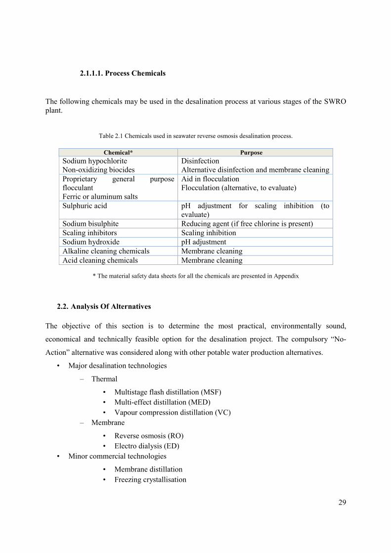
2.1.1.1. Process Chemicals
The following chemicals may be used in the desalination process at various stages of the SWRO plant.
Table 2.1 Chemicals used in seawater reverse osmosis desalination process.
Chemical* Purpose
Sodium hypochlorite Non-oxidizing biocides
Disinfection Alternative disinfection and membrane cleaning
Proprietary general purpose flocculant Ferric or aluminum salts
Aid in flocculation Flocculation (alternative, to evaluate)
Sulphuric acid pH adjustment for scaling inhibition (to evaluate)
Sodium bisulphite Reducing agent (if free chlorine is present)
Scaling inhibitors Scaling inhibition
Sodium hydroxide pH adjustment
Alkaline cleaning chemicals Membrane cleaning
Acid cleaning chemicals Membrane cleaning
* The material safety data sheets for all the chemicals are presented in Appendix
2.2. Analysis Of Alternatives
The objective of this section is to determine the most practical, environmentally sound,
economical and technically feasible option for the desalination project. The compulsory “No-
Action” alternative was considered along with other potable water production alternatives.
• Major desalination technologies
– Thermal
• Multistage flash distillation (MSF)
• Multi-effect distillation (MED)
• Vapour compression distillation (VC)
– Membrane
• Reverse osmosis (RO)
• Electro dialysis (ED)
• Minor commercial technologies
• Membrane distillation
• Freezing crystallisation
30
• Solar humidification
• Future technologies
• Forward osmosis
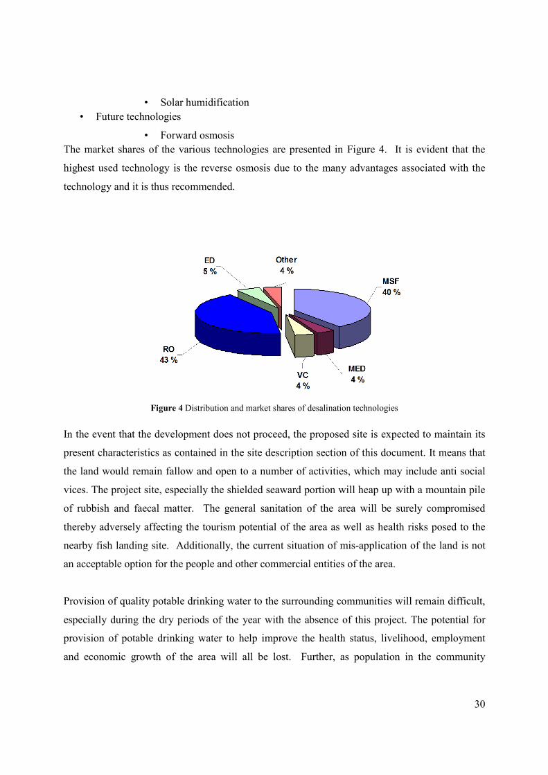
The market shares of the various technologies are presented in Figure 4. It is evident that the
highest used technology is the reverse osmosis due to the many advantages associated with the
technology and it is thus recommended.
Figure 4 Distribution and market shares of desalination technologies
In the event that the development does not proceed, the proposed site is expected to maintain its
present characteristics as contained in the site description section of this document. It means that
the land would remain fallow and open to a number of activities, which may include anti social
vices. The project site, especially the shielded seaward portion will heap up with a mountain pile
of rubbish and faecal matter. The general sanitation of the area will be surely compromised
thereby adversely affecting the tourism potential of the area as well as health risks posed to the
nearby fish landing site. Additionally, the current situation of mis-application of the land is not
an acceptable option for the people and other commercial entities of the area.
Provision of quality potable drinking water to the surrounding communities will remain difficult,
especially during the dry periods of the year with the absence of this project. The potential for
provision of potable drinking water to help improve the health status, livelihood, employment
and economic growth of the area will all be lost. Further, as population in the community

31
increases, coupled with the potential for rise in tourism in the area with its attendant rise in
commercial activities, the demand for potable drinking water in the area is expected to become
overwhelming.
This ‘no action’ option is unacceptable when one considers the costs associated with maintaining
the existing situation without the provision of water using the abundant seawater available in the
area.
32
CHAPTER THREE
3. Baseline Information
This chapter provides site-specific data that forms the initial basis for examining potential
impacts from constructing, operating and decommissioning of proposed SWRO desalination
plant. Specifically, it provides the background for determining if construction and/or post-
construction operations including emergency situations could have persistent, non-localised
positive or adverse impacts to the environment. The first section describes the biophysical
environment while the second portion discusses the socio-economic and cultural environment vis
a vis community’s acceptance of the proposed project. .
3.1. Physical Setting
3.1.1. Location
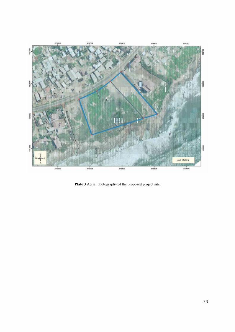
The proposed plant will be located in a seaward plot of land 6.1 acres located 400 m west of the
Dutch Hotel and Nungua fish landing beach, Accra. The land is about six (6) football pitches in
size with tidal access and very close to target population. The plant location and the surrounding
features are shown in aerial photograph of the location (Plate 3). The land is currently used as a
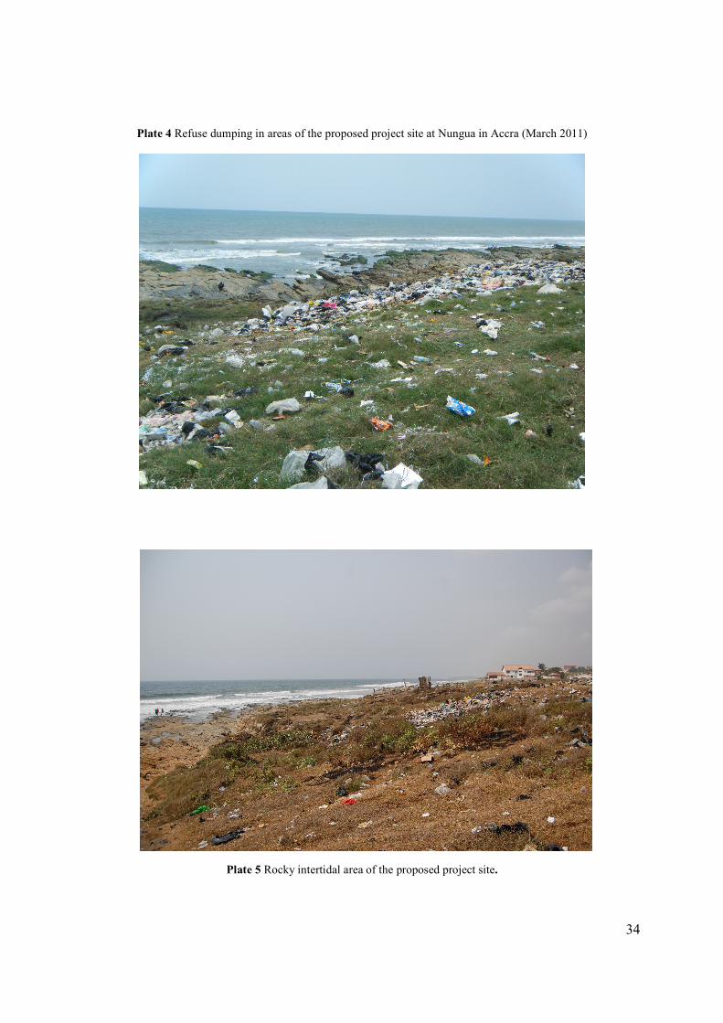
football field for the youth with the seaward portion used as refuses dumping ground (Plate 4).
The seaward end of the site consists of rock outcrops interspersed with coastal scubs (Plate 2).
33
Plate 3 Aerial photography of the proposed project site.
34
Plate 4 Refuse dumping in areas of the proposed project site at Nungua in Accra (March 2011)
Plate 5 Rocky intertidal area of the proposed project site.
35
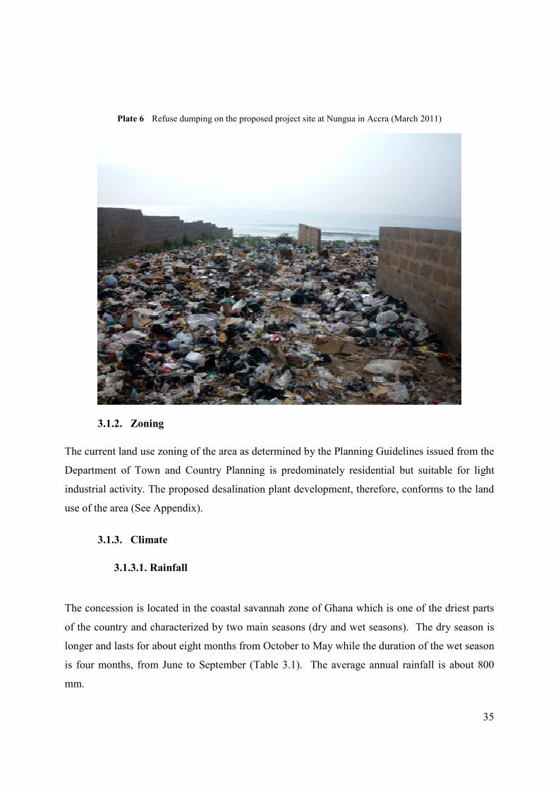
Plate 6 Refuse dumping on the proposed project site at Nungua in Accra (March 2011)
3.1.2. Zoning
The current land use zoning of the area as determined by the Planning Guidelines issued from the
Department of Town and Country Planning is predominately residential but suitable for light
industrial activity. The proposed desalination plant development, therefore, conforms to the land
use of the area (See Appendix).
3.1.3. Climate
3.1.3.1. Rainfall
The concession is located in the coastal savannah zone of Ghana which is one of the driest parts
of the country and characterized by two main seasons (dry and wet seasons). The dry season is
longer and lasts for about eight months from October to May while the duration of the wet season
is four months, from June to September (Table 3.1). The average annual rainfall is about 800
mm.
36
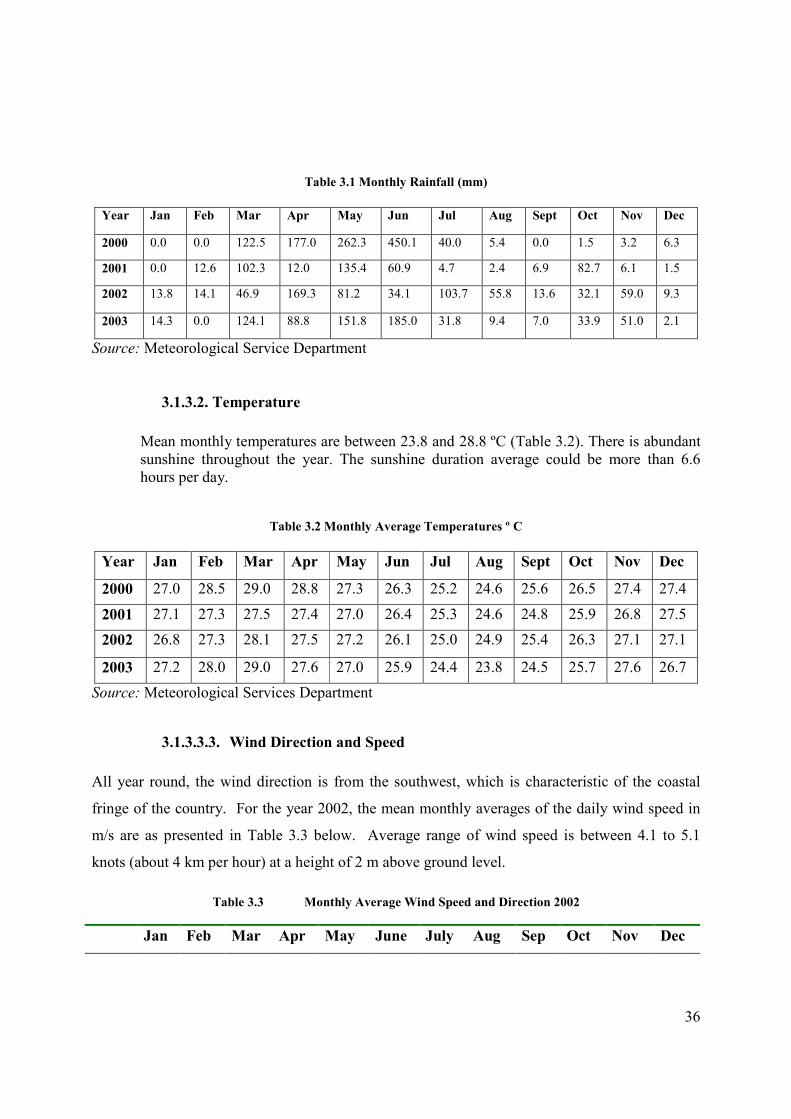
Table 3.1 Monthly Rainfall (mm)
Year Jan Feb Mar Apr May Jun Jul Aug Sept Oct Nov Dec
2000 0.0 0.0 122.5 177.0 262.3 450.1 40.0 5.4 0.0 1.5 3.2 6.3
2001 0.0 12.6 102.3 12.0 135.4 60.9 4.7 2.4 6.9 82.7 6.1 1.5
2002 13.8 14.1 46.9 169.3 81.2 34.1 103.7 55.8 13.6 32.1 59.0 9.3
2003 14.3 0.0 124.1 88.8 151.8 185.0 31.8 9.4 7.0 33.9 51.0 2.1
Source: Meteorological Service Department
3.1.3.2. Temperature
Mean monthly temperatures are between 23.8 and 28.8 ºC (Table 3.2). There is abundant sunshine throughout the year. The sunshine duration average could be more than 6.6 hours per day.
Table 3.2 Monthly Average Temperatures º C
Year Jan Feb Mar Apr May Jun Jul Aug Sept Oct Nov Dec
2000 27.0 28.5 29.0 28.8 27.3 26.3 25.2 24.6 25.6 26.5 27.4 27.4
2001 27.1 27.3 27.5 27.4 27.0 26.4 25.3 24.6 24.8 25.9 26.8 27.5
2002 26.8 27.3 28.1 27.5 27.2 26.1 25.0 24.9 25.4 26.3 27.1 27.1
2003 27.2 28.0 29.0 27.6 27.0 25.9 24.4 23.8 24.5 25.7 27.6 26.7
Source: Meteorological Services Department
3.1.3.3.3. Wind Direction and Speed
All year round, the wind direction is from the southwest, which is characteristic of the coastal
fringe of the country. For the year 2002, the mean monthly averages of the daily wind speed in
m/s are as presented in Table 3.3 below. Average range of wind speed is between 4.1 to 5.1
knots (about 4 km per hour) at a height of 2 m above ground level.
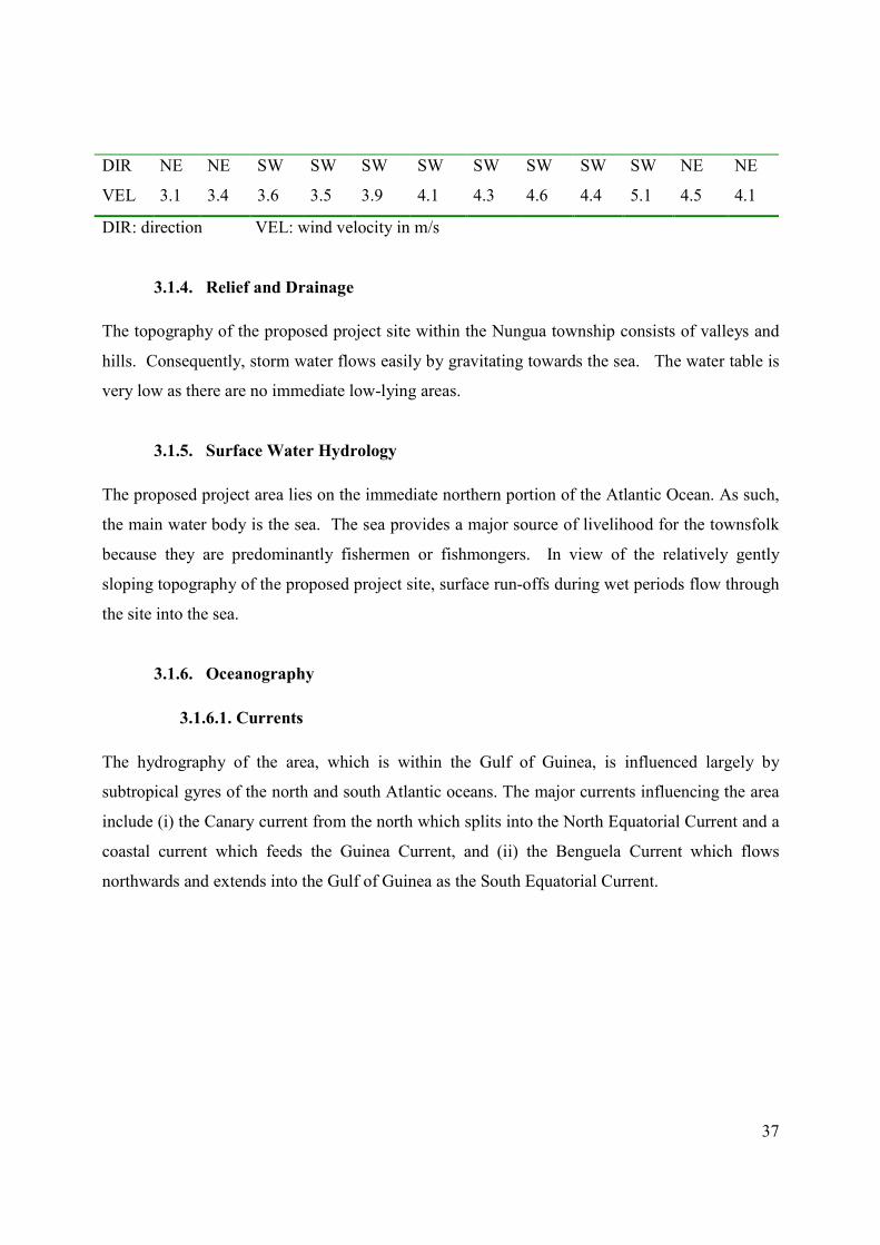
Table 3.3 Monthly Average Wind Speed and Direction 2002
Jan Feb Mar Apr May June July Aug Sep Oct Nov Dec
37
DIR NE NE SW SW SW SW SW SW SW SW NE NE
VEL 3.1 3.4 3.6 3.5 3.9 4.1 4.3 4.6 4.4 5.1 4.5 4.1
DIR: direction VEL: wind velocity in m/s
3.1.4. Relief and Drainage
The topography of the proposed project site within the Nungua township consists of valleys and
hills. Consequently, storm water flows easily by gravitating towards the sea. The water table is
very low as there are no immediate low-lying areas.
3.1.5. Surface Water Hydrology
The proposed project area lies on the immediate northern portion of the Atlantic Ocean. As such,
the main water body is the sea. The sea provides a major source of livelihood for the townsfolk
because they are predominantly fishermen or fishmongers. In view of the relatively gently
sloping topography of the proposed project site, surface run-offs during wet periods flow through
the site into the sea.
3.1.6. Oceanography
3.1.6.1. Currents
The hydrography of the area, which is within the Gulf of Guinea, is influenced largely by
subtropical gyres of the north and south Atlantic oceans. The major currents influencing the area
include (i) the Canary current from the north which splits into the North Equatorial Current and a
coastal current which feeds the Guinea Current, and (ii) the Benguela Current which flows
northwards and extends into the Gulf of Guinea as the South Equatorial Current.
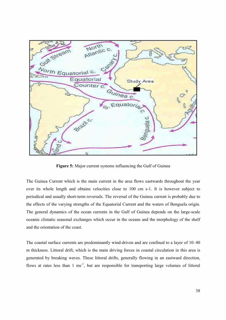
38
Figure 5: Major current systems influencing the Gulf of Guinea
The Guinea Current which is the main current in the area flows eastwards throughout the year
over its whole length and obtains velocities close to 100 cm s-1. It is however subject to
periodical and usually short-term reversals. The reversal of the Guinea current is probably due to
the effects of the varying strengths of the Equatorial Current and the waters of Benguela origin.
The general dynamics of the ocean currents in the Gulf of Guinea depends on the large-scale
oceanic climatic seasonal exchanges which occur in the oceans and the morphology of the shelf
and the orientation of the coast.
The coastal surface currents are predominantly wind-driven and are confined to a layer of 10–40
m thickness. Littoral drift, which is the main driving forces in coastal circulation in this area is
generated by breaking waves. These littoral drifts, generally flowing in an eastward direction,
flows at rates less than 1 ms-1, but are responsible for transporting large volumes of littoral
39
sediments and also for rip currents which are more localized in their action, but move appreciable
amount of sediments away from the coast.
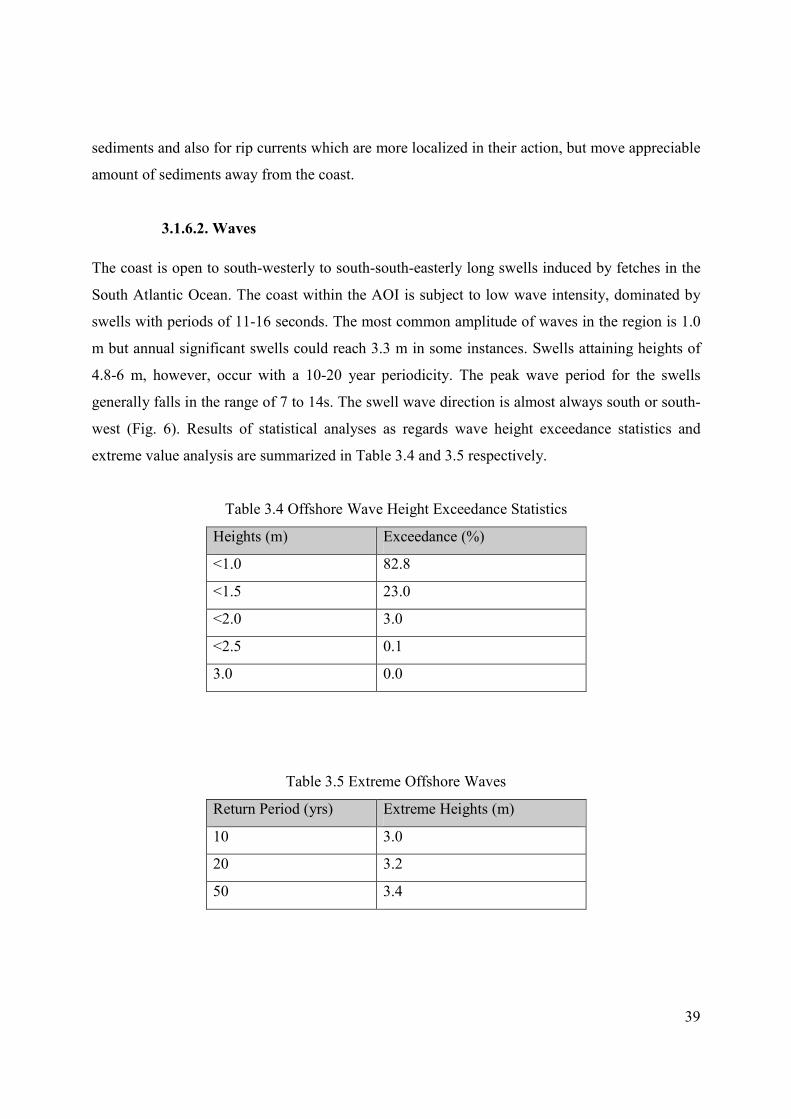
3.1.6.2. Waves
The coast is open to south-westerly to south-south-easterly long swells induced by fetches in the
South Atlantic Ocean. The coast within the AOI is subject to low wave intensity, dominated by
swells with periods of 11-16 seconds. The most common amplitude of waves in the region is 1.0
m but annual significant swells could reach 3.3 m in some instances. Swells attaining heights of
4.8-6 m, however, occur with a 10-20 year periodicity. The peak wave period for the swells
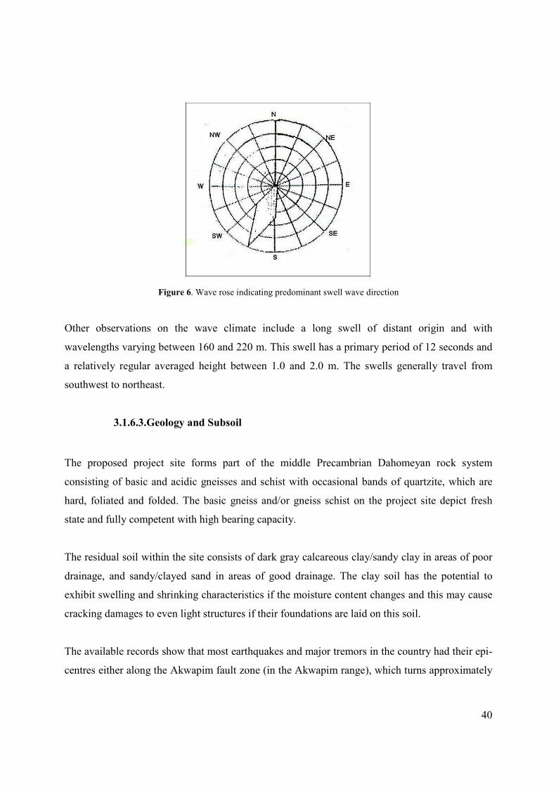
generally falls in the range of 7 to 14s. The swell wave direction is almost always south or south-
west (Fig. 6). Results of statistical analyses as regards wave height exceedance statistics and
extreme value analysis are summarized in Table 3.4 and 3.5 respectively.
Table 3.4 Offshore Wave Height Exceedance Statistics
Heights (m) Exceedance (%)
<1.0 82.8
<1.5 23.0
<2.0 3.0
<2.5 0.1
3.0 0.0
Table 3.5 Extreme Offshore Waves
Return Period (yrs) Extreme Heights (m)
10 3.0
20 3.2
50 3.4
40
Figure 6. Wave rose indicating predominant swell wave direction
Other observations on the wave climate include a long swell of distant origin and with
wavelengths varying between 160 and 220 m. This swell has a primary period of 12 seconds and
a relatively regular averaged height between 1.0 and 2.0 m. The swells generally travel from
southwest to northeast.
3.1.6.3.Geology and Subsoil
The proposed project site forms part of the middle Precambrian Dahomeyan rock system
consisting of basic and acidic gneisses and schist with occasional bands of quartzite, which are
hard, foliated and folded. The basic gneiss and/or gneiss schist on the project site depict fresh
state and fully competent with high bearing capacity.
The residual soil within the site consists of dark gray calcareous clay/sandy clay in areas of poor
drainage, and sandy/clayed sand in areas of good drainage. The clay soil has the potential to
exhibit swelling and shrinking characteristics if the moisture content changes and this may cause
cracking damages to even light structures if their foundations are laid on this soil.
The available records show that most earthquakes and major tremors in the country had their epi-
centres either along the Akwapim fault zone (in the Akwapim range), which turns approximately
41
NE-SW in the location of west Accra, or along the coastal boundary faults which lies some 3 Km
offshore and runs almost parallel to the coastline of Accra. The proposed project site is a distance
away from the two causative zones. Information from the proposed project site did not indicate
any evidence of geological instability or major geological discontinuities like fault. Further, the
area falls within iso-seismal line of intensity VI (developed for the country based on Modified
Mercalli scale I-X, with X the highest and shows high risk of seismic damage), which qualifies
the site as low risk seismic damage area. The details of the hydro-geological and soil study are
attached at Appendix.
3.1.7. Hydrogeology
The few shallow boreholes and hand dug wells of depths 60-80 m within the Nungua areas
indicate that the aquifers are not commercially viable. The volumes of fresh water from such
depths meet domestic use. However, it is envisaged that greater volumes of underground water
could be obtained within depths of about 150-200 m.
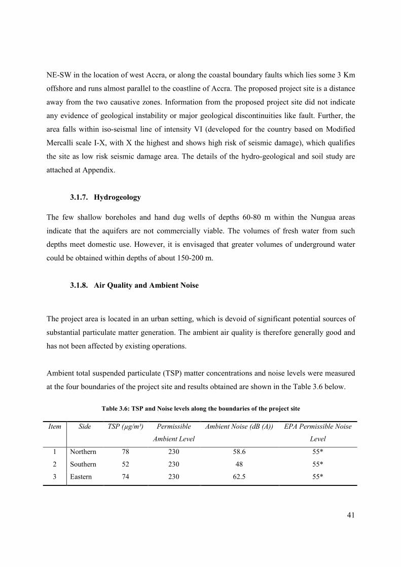
3.1.8. Air Quality and Ambient Noise
The project area is located in an urban setting, which is devoid of significant potential sources of
substantial particulate matter generation. The ambient air quality is therefore generally good and
has not been affected by existing operations.
Ambient total suspended particulate (TSP) matter concentrations and noise levels were measured
at the four boundaries of the project site and results obtained are shown in the Table 3.6 below.
Table 3.6: TSP and Noise levels along the boundaries of the project site
Item Side TSP (µg/m³) Permissible
Ambient Level
Ambient Noise (dB (A)) EPA Permissible Noise
Level
1 Northern 78 230 58.6 55*
2 Southern 52 230 48 55*
3 Eastern 74 230 62.5 55*
42
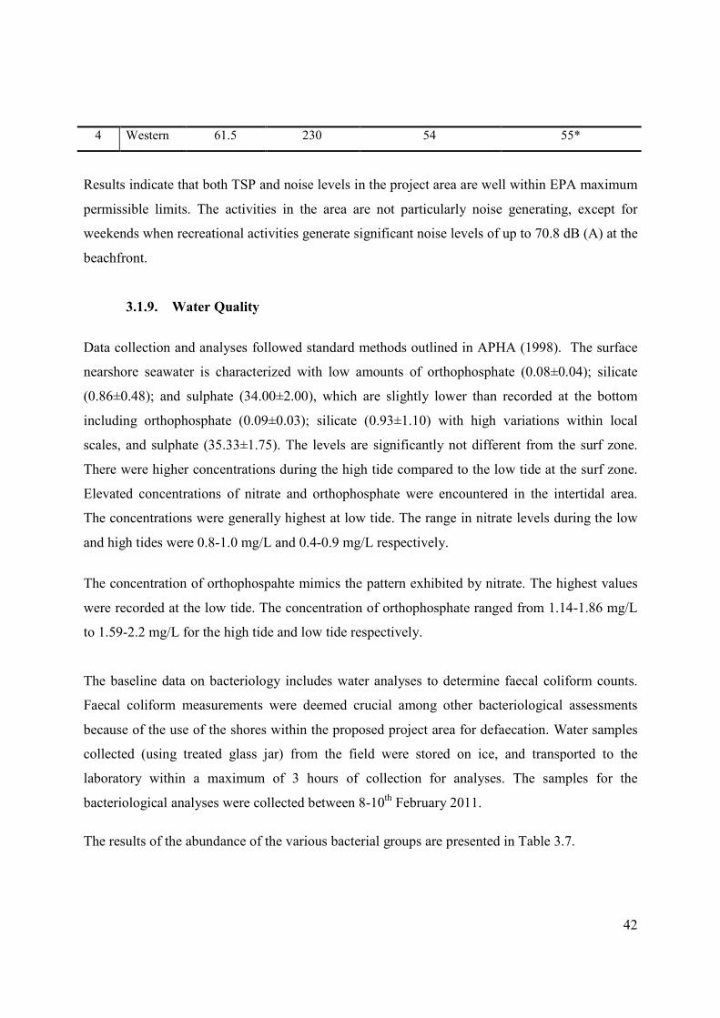
4 Western 61.5 230 54 55*
Results indicate that both TSP and noise levels in the project area are well within EPA maximum
permissible limits. The activities in the area are not particularly noise generating, except for
weekends when recreational activities generate significant noise levels of up to 70.8 dB (A) at the
beachfront.
3.1.9. Water Quality
Data collection and analyses followed standard methods outlined in APHA (1998). The surface
nearshore seawater is characterized with low amounts of orthophosphate (0.08±0.04); silicate
(0.86±0.48); and sulphate (34.00±2.00), which are slightly lower than recorded at the bottom
including orthophosphate (0.09±0.03); silicate (0.93±1.10) with high variations within local
scales, and sulphate (35.33±1.75). The levels are significantly not different from the surf zone.
There were higher concentrations during the high tide compared to the low tide at the surf zone.
Elevated concentrations of nitrate and orthophosphate were encountered in the intertidal area.
The concentrations were generally highest at low tide. The range in nitrate levels during the low
and high tides were 0.8-1.0 mg/L and 0.4-0.9 mg/L respectively.
The concentration of orthophospahte mimics the pattern exhibited by nitrate. The highest values
were recorded at the low tide. The concentration of orthophosphate ranged from 1.14-1.86 mg/L
to 1.59-2.2 mg/L for the high tide and low tide respectively.
The baseline data on bacteriology includes water analyses to determine faecal coliform counts.
Faecal coliform measurements were deemed crucial among other bacteriological assessments
because of the use of the shores within the proposed project area for defaecation. Water samples
collected (using treated glass jar) from the field were stored on ice, and transported to the
laboratory within a maximum of 3 hours of collection for analyses. The samples for the
bacteriological analyses were collected between 8-10th February 2011.
The results of the abundance of the various bacterial groups are presented in Table 3.7.
43
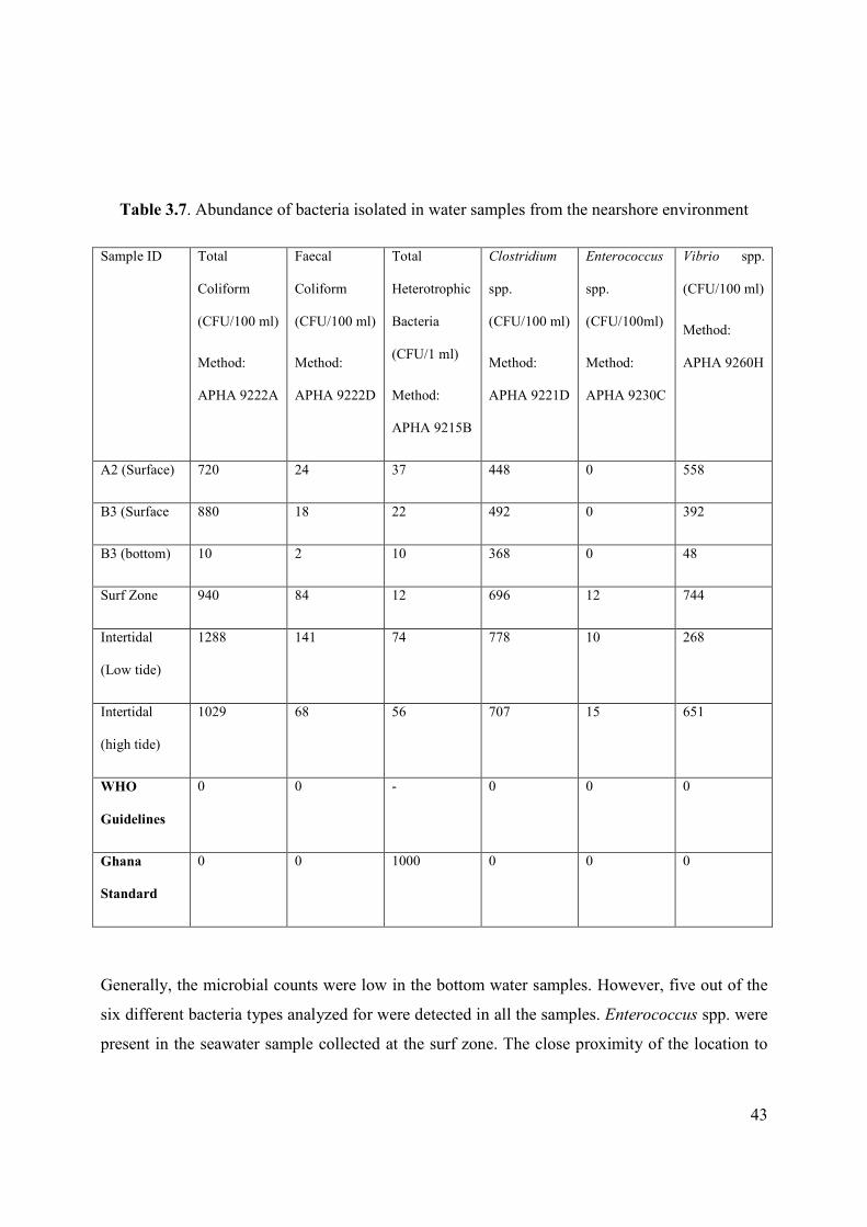
Table 3.7. Abundance of bacteria isolated in water samples from the nearshore environment
Sample ID Total
Coliform
(CFU/100 ml)
Method:
APHA 9222A
Faecal
Coliform
(CFU/100 ml)
Method:
APHA 9222D
Total
Heterotrophic
Bacteria
(CFU/1 ml)
Method:
APHA 9215B
Clostridium
spp.
(CFU/100 ml)
Method:
APHA 9221D
Enterococcus
spp.
(CFU/100ml)
Method:
APHA 9230C
Vibrio spp.
(CFU/100 ml)
Method:
APHA 9260H
A2 (Surface) 720 24 37 448 0 558
B3 (Surface 880 18 22 492 0 392
B3 (bottom) 10 2 10 368 0 48
Surf Zone 940 84 12 696 12 744
Intertidal
(Low tide)
1288 141 74 778 10 268
Intertidal
(high tide)
1029 68 56 707 15 651
WHO
Guidelines
0 0 - 0 0 0
Ghana
Standard
0 0 1000 0 0 0
Generally, the microbial counts were low in the bottom water samples. However, five out of the
six different bacteria types analyzed for were detected in all the samples. Enterococcus spp. were
present in the seawater sample collected at the surf zone. The close proximity of the location to
44
the shoreline could be attributed to the occurrence since the shorelines are used for defaecation.
Further, the concentrations of the bacteria types were generally higher at the surf zone compared
to the other locations beyond the zone. The intertidal zone recorded the highest bacterial load
especially during the low tide which is slightly inconsistent with the observation in the surf zone.
Almost all the bacterial species analyzed were found within the intertidal areas. The levels of the
bacteria present in the samples are an indication of pollution in the nearshore environment of the
proposed project site.
The acceptable microbial limits for various usage of waters include, (a) Recreational waters that
have full contact, the level of faecal coliform should be less than 130 cfu/100 ml. (b) Recreational
waters that have intermediate contact, and the level should be less than 1000. (c) For fishing and
boating the permissible limit is less than 5000 cfu /100ml.
The results of the total and faecal coliform counts in the present study based on recommended
limits of presence of the coliforms in water (WHO, 1990), make the water samples, suitable for
secondary contacts such as boating and fishing. None of the seawater samples in their present
state, however, qualify as potable water. Handling and contact with the water must be done with
utmost caution due to the high levels of the pathogens detected.
3.2. Biological Setting
Though, overall impact of project on fauna and flora has been appears insignificant, because of
the paucity of species and their abundance compared to the gains of the project, it is worth
providing a description of the biological setting of the project site.
3.2.1. Intertidal rocky shore Flora and Fauna
The flora and fauna on the rocky intertidal area were determined along a stretch of 200 m
adjoining the proposed project site. The area is gently flat with several boulders forming different
types of tidal pools. A striking feature in the rocky area was the distinct colour zonation of flora
on the rock substrate. A semi-quantitative benthic assessment was carried out on the rocky shore.
The taxonomic identification of the flora and fauna was possible using taxonomic manuals and
45
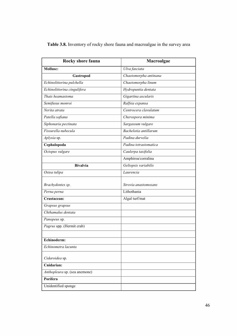
articles (e.g., Edmunds 1978; Lawson 1956). The species list of the rocky shore fauna and flora
encountered is depicted in Table 3. A total of twenty one (21) individual species of rocky shore
epibenthic fauna were encountered. These consisted nine (9) gastropods, three (3) bivalves, one
(1) cephalopod, four (4) crustaceans, two (2) echinoderm (echinoidea), one (1) actinaria
(Cnidarian) and an unidentified sea sponge (Porifera) (Table 3.8). The most common gastropod
encountered, numerically and spatially, was the upper shore littorinid, Echinolittorina pulchella
interspersed patchily with E. cingulifera. Nevertheless, the cirripid crustacean, Chthamalus
dentata was conspicuously abundant constituting approximately 25% of the coverage area. The
presence of rock boulders and myriad tidal pools created many microhabitats giving rise to
various vertical zonations. Thus, typical lower littoral species were found overlapping in the mid-
littoral areas and vice versa.
The number of macroalgal species encountered were 19 (Table 3.8) with the dominant species
being Ulva fasciata (28%), Sargassum vulgare (16%) and Hydropuntia dentata (14%) in that
decreasing order. The other species were found in patches on the rocks and rock crevices along
the study stretch The Caulerpa taxifolia was one species found in patches distribution along the
200 m stretch. The presence and numbers of Caulerpa taxifolia in the area may be an indication
of the levels of nitrate and orthophosphate in the water emanating from faecal material. A clear
distinct band of the flora from the upper intertidal to the lower intertidal was obvious during low
tide period. It is worth stating that these benthic organisms have been recorded in other rocky
areas along the coastline of Ghana.
46
Table 3.8. Inventory of rocky shore fauna and macroalgae in the survey area
Rocky shore fauna Macroalgae
Mollusc: Ulva fasciata
Gastropod Chaetomorpha antinana
Echinolittorina pulchella Chaetomorpha linum
Echinolittorina cingulifera Hydropuntia dentata
Thais heamastoma Gigartina ascularis
Semifusus monroi Ralfsia expansa
Nerita atrata Centrocera clavulatum
Patella safiana Cherospora minima
Siphonaria pectinata Sargassum vulgare
Fissurella nubecula Bachelotia antillarum
Aplysia sp. Padina durvelia
Cephalopoda Padina tetrastomatica
Octopus vulgare Caulerpa taxifolia
Amphiroa/corralina
Bivalvia Geliopsis variabilis
Ostea tulipa Laurencia
Brachydontes sp. Strovia anastomosans
Perna perna Lithothania
Crustacean: Algal turf/mat
Grapsus grapsus
Chthamalus dentata
Panopeus sp.
Pagrus spp. (Hermit crab)
Echinoderm:
Echinometra lacunta
Cidaroidea sp.
Cnidarian:
Anthopleura sp. (sea anemone)
Porifera
Unidentified sponge
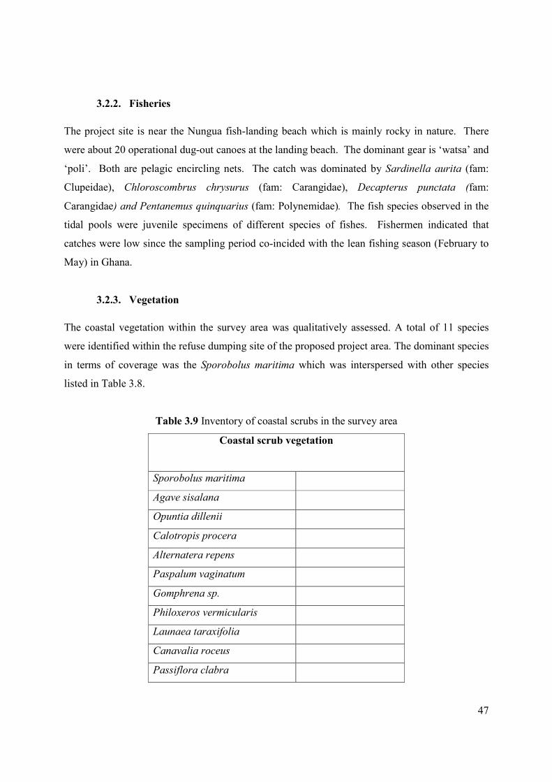
47
3.2.2. Fisheries
The project site is near the Nungua fish-landing beach which is mainly rocky in nature. There
were about 20 operational dug-out canoes at the landing beach. The dominant gear is ‘watsa’ and
‘poli’. Both are pelagic encircling nets. The catch was dominated by Sardinella aurita (fam:
Clupeidae), Chloroscombrus chrysurus (fam: Carangidae), Decapterus punctata (fam:
Carangidae) and Pentanemus quinquarius (fam: Polynemidae). The fish species observed in the
tidal pools were juvenile specimens of different species of fishes. Fishermen indicated that
catches were low since the sampling period co-incided with the lean fishing season (February to
May) in Ghana.
3.2.3. Vegetation
The coastal vegetation within the survey area was qualitatively assessed. A total of 11 species
were identified within the refuse dumping site of the proposed project area. The dominant species
in terms of coverage was the Sporobolus maritima which was interspersed with other species
listed in Table 3.8.
Table 3.9 Inventory of coastal scrubs in the survey area
Coastal scrub vegetation
Sporobolus maritima
Agave sisalana
Opuntia dillenii
Calotropis procera
Alternatera repens
Paspalum vaginatum
Gomphrena sp.
Philoxeros vermicularis
Launaea taraxifolia
Canavalia roceus
Passiflora clabra
48
3.3. Background
Nungua is located on latitude 5’60º N and longitude 0’07º W. Nungua along the Atlantic Ocean
and 18-22 km southwest of Accra city centre. The topography of the area is generally undulating
with heights ranging from 250 feet above sea level and barely reaching 500 ft. It has partly
rugged coastline with few beaches; very few of them are developed and maintained as social and
recreational centres.
Very few water channels exist in the area and are generally shallow and depend on the local rain
for their flow. The vegetation of the area is similar to what pertains in parts of the Accra plains.
Vegetation is mainly grasses and shrubs with coconut trees along the coast. Some mangrove
vegetation also occurs along lagoons. Rainfall in the area is generally low with an average annual
total of about 700 mm.
The 2008 estimated population of the Teshie Nungua population is 261,571. With a total land
area estimated at 50 square kilometres, the general population density is calculated as 5,231
persons per square kilometer. The population of the Municipality has a youthful nature with
50.7% the population under the age of 24years.
Fishing, farming and petty trading are the predominant economic activities in the Nungua area.
Carving and carpentry have also become more important economic activities in these locals over
the years.
The most significant ethnic group in terms of numbers are the Ga-Adangbe, Akans, Hausas,
Guans, Mole-Dagbani and other minority groups. It is estimated that Christians form about 69%
of the population followed by Muslims with 15.6%, 9% traditionalist and other religions forming
the remainder.
Nungua enjoys basic infrastructure comprising water from Ghana Water Company Limited
(GWCL) and electrical power from Electricity Company of Ghana (ECG). Nungua has one
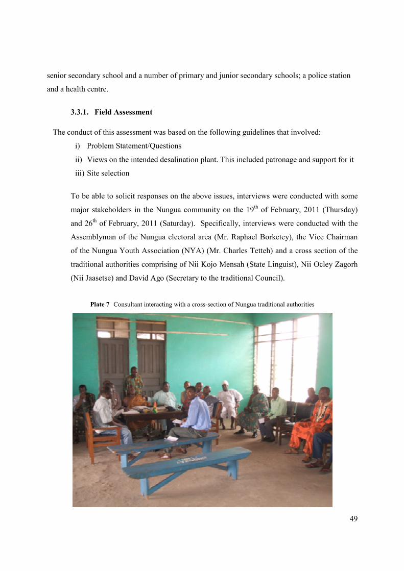
49
senior secondary school and a number of primary and junior secondary schools; a police station
and a health centre.
3.3.1. Field Assessment
The conduct of this assessment was based on the following guidelines that involved:
i) Problem Statement/Questions
ii) Views on the intended desalination plant. This included patronage and support for it
iii) Site selection
To be able to solicit responses on the above issues, interviews were conducted with some
major stakeholders in the Nungua community on the 19th of February, 2011 (Thursday)
and 26th of February, 2011 (Saturday). Specifically, interviews were conducted with the
Assemblyman of the Nungua electoral area (Mr. Raphael Borketey), the Vice Chairman
of the Nungua Youth Association (NYA) (Mr. Charles Tetteh) and a cross section of the
traditional authorities comprising of Nii Kojo Mensah (State Linguist), Nii Ocley Zagorh
(Nii Jaasetse) and David Ago (Secretary to the traditional Council).
Plate 7 Consultant interacting with a cross-section of Nungua traditional authorities
50
a) State of the Water Problem
It was clearly established by all parties interviewed that Nungua faces a very acute problem with
water supply. The Assemblyman recounted that in the best of times, water flows three days in a
week; namely on Saturdays, Sundays and Wednesdays. For an area called ‘Adogono’, water may
not flow through the taps for periods exceeding one month due to low pressure in the pipelines.
The general contention of the respondents was that in the past when the population of the
township was small, water supply was less problematic. However with increasing demand for
water due to rapid population increase, the water flow is not only inadequate, but also irregular.
The Youth leader further alluded to the fact that lack of potable water at various times compels
the already impoverished people to buy water at the cost of ¢10 GH cedi (about US $7) per
bucket.
b) Views and Opinions on the Desalination Plant
Diverse views were expressed by these representative groups on the intended plant. There was
strong support for its establishment. According to the Assemblyman it was a laudable one which
they fully support and were also prepared to use and pay for its services. He also contended that
if the project becomes operational it would ease the water problems and its associated tensions.
However some apprehensions were expressed about the potential cost of accessing the service. In
the view of the state linguist of the traditional council “the sea is ours and hence water from it
should not be expensive”. He further contended that “in so far as the water is clean and the
production process not problematic, that is if smoke emissions and other pollutants are managed
well, we support it”.
The Assemblyman suggested that the government should be made to provide subsidy for
consumers if the end product proved to be too expensive for them. He was very supportive of it
as the project was likely to generate employment for the people in the area. He pledged his
unflinching support indicating further that “water is life and no one can live without it; it cannot
be compared to electricity as we can live without electricity”.
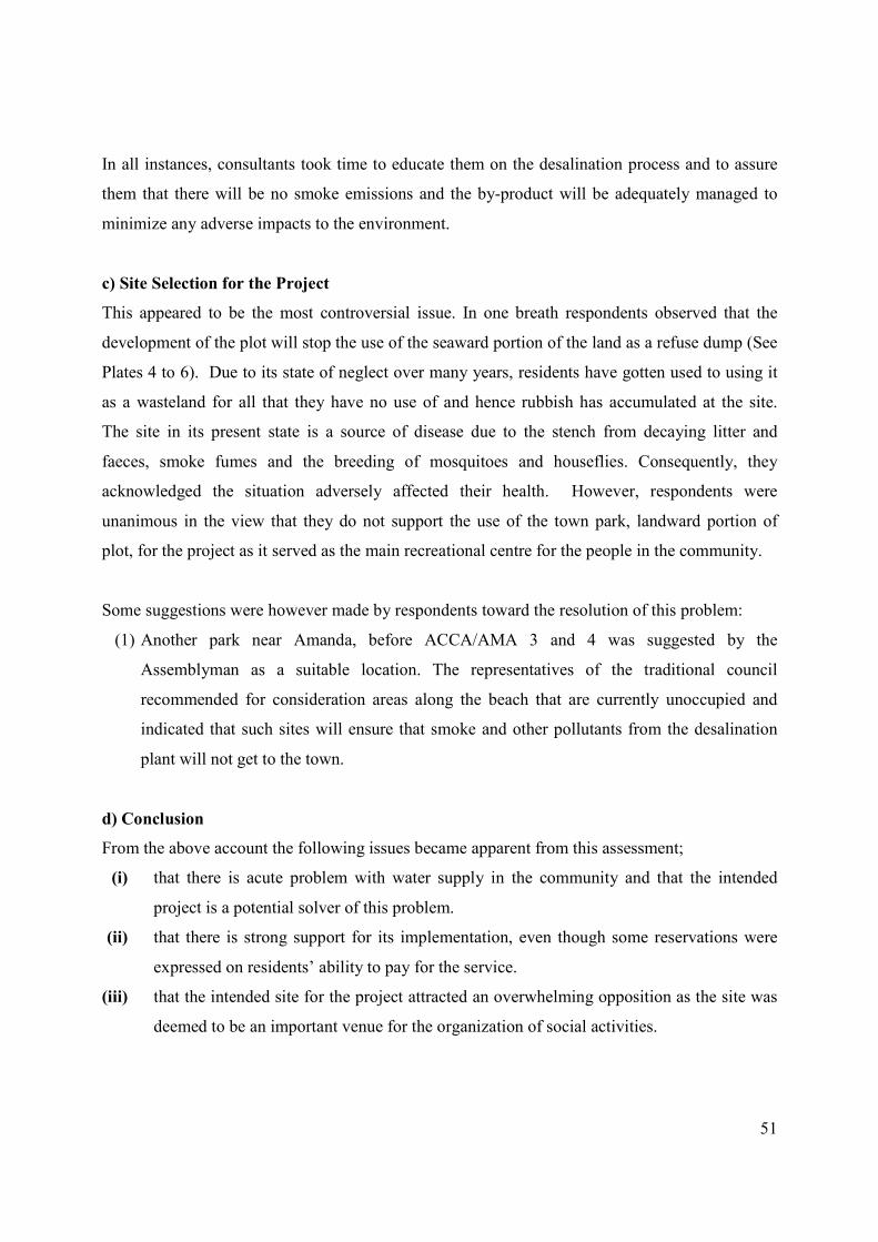
51
In all instances, consultants took time to educate them on the desalination process and to assure
them that there will be no smoke emissions and the by-product will be adequately managed to
minimize any adverse impacts to the environment.
c) Site Selection for the Project
This appeared to be the most controversial issue. In one breath respondents observed that the
development of the plot will stop the use of the seaward portion of the land as a refuse dump (See
Plates 4 to 6). Due to its state of neglect over many years, residents have gotten used to using it
as a wasteland for all that they have no use of and hence rubbish has accumulated at the site.
The site in its present state is a source of disease due to the stench from decaying litter and
faeces, smoke fumes and the breeding of mosquitoes and houseflies. Consequently, they
acknowledged the situation adversely affected their health. However, respondents were
unanimous in the view that they do not support the use of the town park, landward portion of
plot, for the project as it served as the main recreational centre for the people in the community.
Some suggestions were however made by respondents toward the resolution of this problem:
(1) Another park near Amanda, before ACCA/AMA 3 and 4 was suggested by the
Assemblyman as a suitable location. The representatives of the traditional council
recommended for consideration areas along the beach that are currently unoccupied and
indicated that such sites will ensure that smoke and other pollutants from the desalination
plant will not get to the town.
d) Conclusion
From the above account the following issues became apparent from this assessment;
(i) that there is acute problem with water supply in the community and that the intended
project is a potential solver of this problem.
(ii) that there is strong support for its implementation, even though some reservations were
expressed on residents’ ability to pay for the service.
(iii) that the intended site for the project attracted an overwhelming opposition as the site was
deemed to be an important venue for the organization of social activities.
52
(iv) Suggestions made to overcome this problem included the use of another park as well as
other parts of the beach that remain unoccupied.
At all the sessions much education was given to respondents from the three main groups, viz
Nungua traditional council, Youth group, and the Assemblyman and his entourage, on the various
issues raised in the above narrative. Consultants provided very illustrative insights on the
potential offered by the desalination plant development to help improve the socio-economic and
overall health status of the people of Nungua. Further discussions centered on the people using
those suggested alternative sites for recreation in order to allow the project to continue at the
present identified site since all legal documents governing the acquisition of the site are intact
with the proponents. Consultants underscored the need for continuous dialogue between the
community groups and proponents to ensure peaceful development of the area; contact addresses
were therefore exchanged. At the end of the sessions, there was understanding and
overwhelming support for the project from all sides.
53
CHAPTER FOUR
4. Other Consultations
The following institutions were consulted to facilitate the identification of key environmental and
other concerns associated with the proposed project and the outcomes are presented below.
4.1. Lands Commission Secretariat / Land owner
The Lands Commission was consulted during the acquisition of the land for their concurrence, plotting
and processing of the documents for land Title Registration. Similarly, the owner of the land was
contacted for the authenticity of land documentation.
4.2. Accra Metropolitan Assembly
Consultations have been held with the following departments within the Accra Metropolitan
Assembly. These include the Town and Country Planning; Development Control and Works;
Urban Roads, Environmental Health and Waste Management Departments on the proposed
desalination plant project. The deliberations centered on zoning status, right of way (ROW) for
export pipelines, waste management issues, approval of development and acquisition of building
permit from Kpeshie Town and Country Planning Committee and monitoring during
construction, operational and decommissioning phases of the project. Discussions were also held
with the Assemblyman for the Nungua electoral area.
4.3. Environmental Protection Agency (EPA)
The EPA has the responsibility of evaluating the environmental acceptability of the proposed
project and also ensures that proponents comply with the provisions of the Environmental
Protection Agency Act 1994 (Act 490), and the Environmental Assessment Regulations 1999 (LI
1652).
54
The Ghana Environmental Protection Agency (EPA) was consulted in an application for an
environmental permit. It duly registered the project and directed for Preliminary Environmental
Assessment (PEA) to be carried out. Upon submission of the draft PER by proponent, it was
reviewed by EPA with comments that have gone into the finalisation of this PER.
4.4. Electricity Company of Ghana (ECG)
The Kpeshie District Office of the Electricity Company of Ghana has been contacted to
determine the adequacy of the current electrical power supply and provision of direct power
supply to the project site.
4.5. Ghana Water Company Limited (GWCL)
The management of GWCL has been consulted on water quality standards, project design
including ROW for export pipelines, and marketing and distribution of the potable water to be
produced by Befesa.
4.6. Public Utilities Regulatory Commission (PURC)
The commission has been contacted as a regulator of the water industry in Ghana to provide
information on the dynamics to be introduced into the water provision sector with the coming
into place of the project.
4.7. Ghana Telecom
Supply of telephone lines to the site has been discussed with the Ghana Telecom, which has
assured that more fixed telephone lines would be extended to the site prior to the completion of
the project. Currently the area is connected with the cellular phone networks.
4.8. Ghana National Fire Service (GNFS)
The GNFS has the responsibility of ensuring that all development that are associated with fire
risk install the appropriate equipment and put in the necessary measures to prevent and control
55
any fire hazards. The GNFS has inspected the project site and advised on the types of fire
prevention equipment and control measures to be put in place before the construction, operation,
and decommissioning phases of the project.
4.9. Ghana Standards Board (GSB)
The GSB is the standards agency for all goods and services in Ghana. They were consulted for
information on drinking water quality standards as well as the possibility of their laboratory being
used for testing seawater and potable water as part of a monitoring plan for the project during the
operation phase. The GSB indicated their interest in the end product (i.e. potable water) meeting
the Ghana Standard for Drinking water (GS 175).
56
CHAPTER FIVE
5. Identification of Potential Environmental Impacts
5.1. Impact identification
The potential environmental impacts of the development and operation of the SWRO desalination
plant has been predicted based on the existing conditions and character of segments of the
receiving environment that are likely to be affected by the proposed undertaken. Future
developments of the project area and its immediate environs have also been considered in the
determination and mitigation of identified impacts. The potential environmental impacts have
been identified at the constructional and operational phases of the project.
The impact study in all these categories is designed to ensure that potential negative impact
expected to arise from the development of the project are mitigated or minimised whilst
maximising the expected positive ones. This would ensure project sustainability and enhance
environmental conditions for the benefit of the entire community and its immediate environs.
Certain impacts of less significance have only been mentioned.
The potential major impacts of the project have been identified through literature review and field
studies. Various technical studies and investigations were also conducted. These include
geotechnical investigations on the geology, hydrology and the seismicity of the project site, water
quality and ecological study on the flora and fauna. Further, consultations were also held with all
relevant stakeholders in the project site, relevant institutions and Government Departments and
the metropolitan authority.
57
5.2. Construction Phase
5.2.1. Air quality, Noise and Vibration
Air pollution indicators, particularly the concentration of dust particles in the area may
increase slightly above ambient levels during the construction phase. The alteration in air
quality will be the result of site preparation activities such as vehicular movement.
Haulage of materials and power generators will generate minimum noise at the site and its
immediate environs. Site workers may be exposed to low risk hazards associated with
ambient air and noise pollution, and other forms of vibration. It is important to stress that
only prefabricated facility would be utilised as offices which reduces the need for
concrete structures on the site. Drilling the intertidal areas to lay pipes can have impact on
the environment through:
• The development of turbid plumes in the surface intertidal waters
• The release of chemical drilling additives into the environment
• Alteration of the rocky intertidal areas, the benthic habitat by impacting on the
hard substrate or smothering benthic organisms.
5.2.2. Drainage and erosion
There could be the possibility of soil being eroded along gullies into the sea. Increases in
rainfall intensity/duration and /or slope angle can lead to greater erodability of soils. The
sandy nature of most of the soils within the project site would make them susceptible to
erosion.
5.2.3. Solid waste
Packaging materials such as food wrappers, plastics etc. may be generated at the site from
workers. Solid waste may find their way into the sea following rainfall and strong winds,
and/or intentional disposed off into the sea. These may alter the aesthetic beauty of the
environment if not well managed. Further, it may influence the water quality and the
biotic communities within the intertidal areas.
58
5.2.4. Health and safety
The health and safety of workers will be at risk due to generation of particulate matter and
noise during construction if not managed well. Careful attention will therefore be given
to mitigation of dust, noise, vibration and other hazards in the work environment.
5.2.5. Security and safety
Security and safety would be a source of concern, especially during the construction
phase. Potential security impacts include increased petty crime. In order to adequately
address safety and security issues associated with the construction and operational phases
of the project, a Security Company would be employed to man the site.
5.2.6. Employment and income
In the construction phase, the project will provide job opportunities for both skilled and
unskilled personnel from Nungua and its environs. Limited employment opportunities
exist for both manual and skilled labour where the appointed contractor could make use of
locals. For instance, skilled labour will be needed in the assemblage of prefabricated steel
building to house the plant as well as offices. These opportunities will, however, be of a
short duration. As a result, it is not anticipated that there will be an influx of workers into
the area as a result of the proposed project. A labour force of about 45 is anticipated
during the construction phase.
5.3. Operational Phase Impacts
5.3.1. Noise
During operational stage possible noise generation will be as a result of vehicular
movement to and from the premises and also from the generators that would be installed
to provide alternative power supply.
59
5.3.2. Sewage
Sewage would be generated at the development site and effective treatment and disposal
mechanism is required to safeguard health and integrity of coastline. Townsfolk who
indiscriminately defaecate at the site will not be able to access site. This will help to
reduce the health risks associated with the bad practice.
5.3.3. Security and Safety
Safety and security would be an issue during the operation phase. The safety and security
of workers is paramount and may pose serious impact if not managed. Further, equipment
and chemicals must be secured from theft.
5.3.4. Employment
Limited employment opportunities would exist for skilled labour. For instance, skilled
labour will be needed in the various stages of the desalination process. The project is
expected to employ the services of a total of 20 permanent workers such as administrative
staff security personnel and technical staff. As a result, it is not anticipated that there will
be an influx of workers into the area as a result of the proposed project. In order to
minimise the potential for influx of workers, however, local labour may be utilised as far
as possible. This would provide regular incomes for employees and guarantee them
social security in future. The company undertakes to respect all of the necessary
provisions in the local labour laws to safeguard job security for all workers.
5.3.5. Air Quality
No significant change in air quality is envisaged during the operational phase.
5.3.6. Drainage and erosion
Surface water resources are known to be most susceptible to pollution. Run-off from
storm water passing through the Nungua township will traverse the development plot on
its way to the sea.
60
5.3.7. Potential Impacts on Local Government and Regional Benefits
The implementation of the proposed project is required to meet the growing water
requirements in the Nungua township and its environs. Therefore, indirect benefits could
accrue, as new economic benefits and opportunities could be realised. Payment of levies
and taxes from such economic ventures will generate income for the district assembly.
5.3.8. Potential Impacts on Intertidal Beach Users
The development of the site means townsfolk will be deprived of a recreational park and
an open refuse dump they have used over many years. Discussions are currently on-going
between developers and opinion leaders on a possible relocation plan for especially,
sporting activities.
61
CHAPTER SIX
6. Mitigation of Significant Impacts
6.1. Constructional phase impacts
Most of the impacts identified during the construction phase assessed to be of negligible
to low significance with the implemented of mitigation measures. Measures to prevent,
reduce or mitigate the negative effects of the proposed project are therefore described
below.
6.1.1. Noise and vibration
The Generating plant set would be used as back up in the event power trips. It will be
housed in a honeycomb structure and would be fully lagged with noise-proof materials.
Expected humming from the generators when in operation will not exceed 60 decibels.
This is expected to minimize the noise and vibration.
Because of the open ocean conditions in which drilling would take place within short
duration, the significance of turbid plumes, release of chemical drilling additives, and the
smothering of benthic organisms, the significance of these impacts would be negligible.
6.1.2. Drainage and erosion
Landscaping will follow construction very closely to ensure that loose soil is not eroded
into drainage of the sea. Where possible drains and pipes will be installed to help contain
and dispose of storm water at the site. The following mitigation measures are proposed:
• Steep slopes should be avoided as far as possible throughout the project site.
• Run-offs should be contained and managed within the vicinity of the project site.
• Sand binders may be planted at sources of run-offs within the project site to
minimise or reduce erosion.
62
6.1.3. Solid waste
The Assembly will be contracted to dispose of solid wastes to be generated during the
occupancy phase of the project. Other private solid waste operators will also be contracted
to augment the mechanism to be instituted to dispose off all solid waste.
6.1.4. Health and safety
Concerns on occupational health and safety issues with respect to requirement of
factories, offices and shops (Act 1970) would be strictly observed. Proper health and
safety equipment will be provided for all workers and an in-house health and safety
protocol shall be adhered to. All chemical usage would be carried out with utmost care
following standard procedures. Further, all used chemicals shall be disposed off
adequately and cautiously. Additionally, warning signs shall be erected at both nearshore
and intertidal locations to alert both fishers and other beach users of any potential danger
of laid pipes.
6.1.5. Visual intrusion
During the construction phase, dust and particulate matter likely to be generated would be
controlled by regular sprinkling of water within the vicinity to suppress their re-
suspension.
6.2. Operational Phase Impacts
6.2.1. Noise
The stand-by generators would be placed in a honeycomb structure and each plant set
would have a silencer and lagging (sound proof casing) around the engine to control noise
generation. It is therefore unlikely that the generator would increase the ambient noise
levels significantly above the existing range of 38.4-67.8 dB (A).
63
6.2.2. Air quality
Sulphur dioxide (SO2), smoke, carbon monoxide (CO) and other gaseous pollutants will
constitute major emissions when the generator comes on-line following a power outage.
Adequate dispersion of gases is anticipated in view of the high prevailing wind speed that
exists throughout the year. A stack height of at least 5 m (from ground level) will be
connected to the generator exhaust to enhance dispersion of gaseous and particulate
emissions.
6.2.3. Solid waste
Solid wastes would arise from a number of sources as indicated in Section 5.1.3 and 5.2.2.
Solid wastes (refuse) generated would be managed in similar manner as of the existing
facilities i.e. collected and disposed off on contract by the District Assembly or private
refuse operators. Workers would be educated not to dispose off solid waste into the sea.
6.2.4. Sewage
Sewage at the site would be managed by septic tanks of varied dimensions. The sizes of
the septic tanks depend on the number of expected population to be served. The
dimensions were calculated based on the formula, C=180 (N) +2000 and a per capita
water consumption of 60 L (0.06 m3). Where C = capacity of septic tank, N = population
of occupants and L = litres.
6.2.5. Semi-solid waste
Among the important semi-solid waste to be generated include the brine (concentrated
liquid salt). This will be disposed off through diffusers far offshore. The reverse osmosis,
as a desalination plant, is pressure driven process at ambient temperature. The gross
volume of the brine effluents is at the same temperature as the seawater used as feed to
the plant. Occasionally, temperatures from the small volume of water used in the
maintenance of the membranes may rise up to 33 0C but these are relatively small
quantities that are blended with brine. Due to the current and wave dynamics with the
proposed project location, the brine is expected to disperse as quickly as possible without
64
causing any osmotic effects to marine organisms. It is also believed the steady state or
kinetic principle (or Marcet’s principle of constant proportions) will ensure that the
salinity (of the brine) within the immediate vicinity of the outlet pipes for brine disposal
would be normalized to eliminate the possibility of hypersalinity. Based on the above
information, no adverse impacts are envisaged on aquatic life within and beyond the
immediate environment of the brine outfall pipe.
6.2.6. Security and Safety
The project will ensure that safety of all workers is accorded the needed priority with the
provision of safety equipment such as steel toe boots, hard hats, protective goggles, ear
and nose filters, protective gloves, protective attire etc. Further, in-house safety briefings
will be periodically organized for all types of the work force. Specifically, fire drills and
training in fire fighting, designation of fire assembly point, installation and operation of
smoke detectors, fire extinguishers, etc. will be given the highest priority.
65
CHAPTER SEVEN
7. Provisional Environmental Management Plan
7.1. Monitoring Plan
The project will continue to monitor all wastes generated from its premises to ensure that such
waste streams do not cause harm to human health and the environment as part of an
environmental management plan (EMP). An identified worker will be given full responsibility to
implement and co-ordinate all environmental monitoring activities as part of the EMP.
Ingredients of the EMP include quarterly monitoring of seawater quality. Water quality
parameters such as pH, BOD, Oil and Grease and faecal coliforms would be determined in order
to assess the quality of the resource for water extraction purposes. Special attention will be given
to the quality of drinking water. Contracted laboratories will regularly collect samples for
analyses to ensure that they meet both Ghana’s and WHO drinking water quality standards. For
quality control purposes, two accredited laboratories would be selected to carry out the water
quality analyses. The results would be communicated in annual reports to be submitted to Ghana
EPA. The company will continue to keep proper records of all environmental data at the site. The
Ghana EPA’s environmental quality guidelines will be the yardstick for compliance.
In the case of solid wastes, monitoring will ensure that waste containers are removed on schedule
and the beachfront is not littered with containers, polythene, bottles, corks, etc. The officer in-
charge of the environment will continue to ensure that no burning of waste items is carried out at
the facility.
It would be ensured that workers are provided with protective clothing and wearing of proper
gears would be enforced during the construction phase of the project. Most operational
equipment would be monitored to fix any leakages, replace worn out equipment and conduct
regular safety briefings to workers.
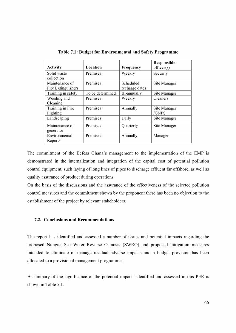
66
Table 7.1: Budget for Environmental and Safety Programme
Activity Location Frequency Responsible
officer(s)
Solid waste collection
Premises Weekly Security
Maintenance of Fire Extinguishers
Premises Scheduled recharge dates
Site Manager
Training in safety To be determined Bi-annually Site Manager
Weeding and Cleaning
Premises Weekly Cleaners
Training in Fire Fighting
Premises Annually Site Manager /GNFS
Landscaping Premises Daily Site Manager
Maintenance of generator
Premises Quarterly Site Manager
Environmental Reports
Premises Annually Manager
The commitment of the Befesa Ghana’s management to the implementation of the EMP is
demonstrated in the internalization and integration of the capital cost of potential pollution
control equipment, such laying of long lines of pipes to discharge effluent far offshore, as well as
quality assurance of product during operations.
On the basis of the discussions and the assurance of the effectiveness of the selected pollution
control measures and the commitment shown by the proponent there has been no objection to the
establishment of the project by relevant stakeholders.
7.2. Conclusions and Recommendations
The report has identified and assessed a number of issues and potential impacts regarding the
proposed Nungua Sea Water Reverse Osmosis (SWRO) and proposed mitigation measures
intended to eliminate or manage residual adverse impacts and a budget provision has been
allocated to a provisional management programme.
A summary of the significance of the potential impacts identified and assessed in this PER is
shown in Table 5.1.
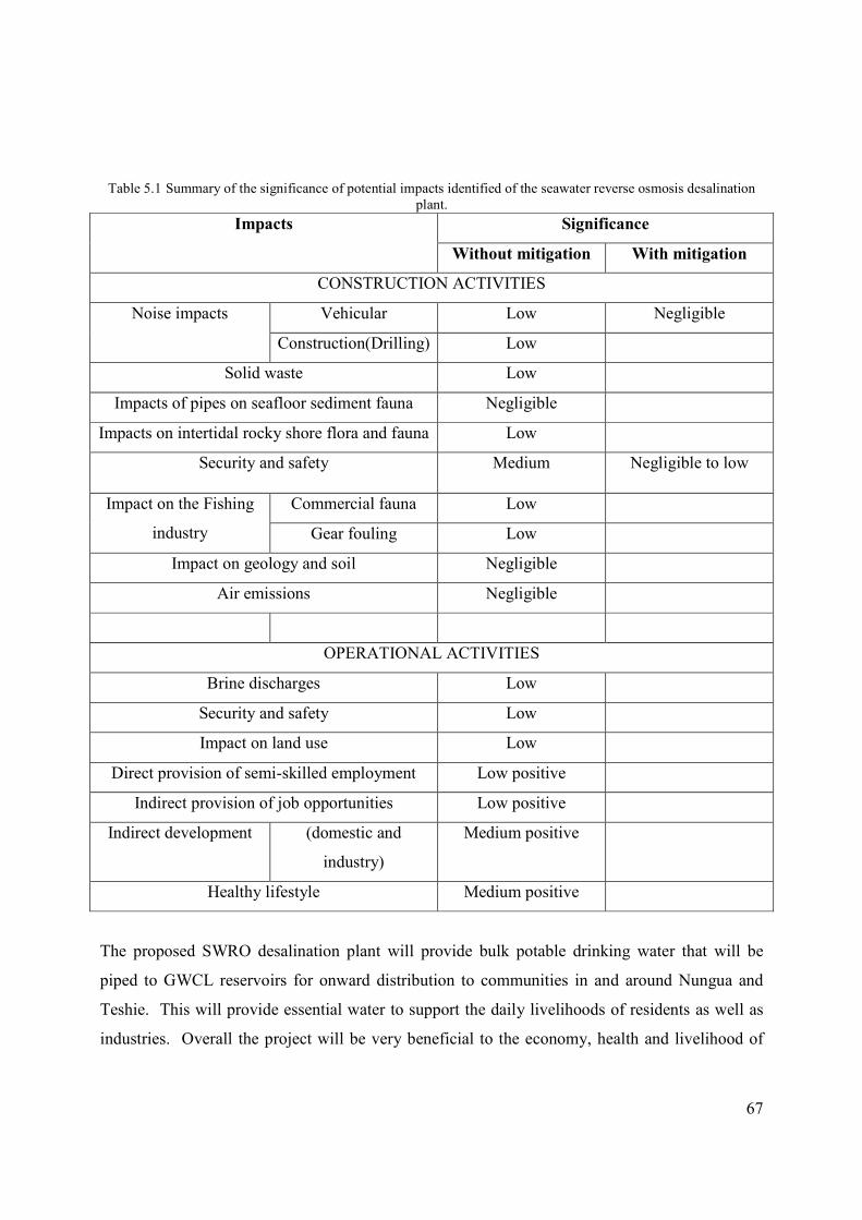
67
Table 5.1 Summary of the significance of potential impacts identified of the seawater reverse osmosis desalination plant.
Impacts Significance
Without mitigation With mitigation
CONSTRUCTION ACTIVITIES
Noise impacts Vehicular Low Negligible
Construction(Drilling) Low
Solid waste Low
Impacts of pipes on seafloor sediment fauna Negligible
Impacts on intertidal rocky shore flora and fauna Low
Security and safety Medium Negligible to low
Impact on the Fishing
industry
Commercial fauna Low
Gear fouling Low
Impact on geology and soil Negligible
Air emissions Negligible
OPERATIONAL ACTIVITIES
Brine discharges Low
Security and safety Low
Impact on land use Low
Direct provision of semi-skilled employment Low positive
Indirect provision of job opportunities Low positive
Indirect development (domestic and
industry)
Medium positive
Healthy lifestyle Medium positive
The proposed SWRO desalination plant will provide bulk potable drinking water that will be
piped to GWCL reservoirs for onward distribution to communities in and around Nungua and
Teshie. This will provide essential water to support the daily livelihoods of residents as well as
industries. Overall the project will be very beneficial to the economy, health and livelihood of

68
the people of Kpeshie sub-metropolitan area. It is our view that the project would promote
economic growth and healthy living in the Nungua community and beyond. When all of the
proposed mitigation measures and environmental monitoring plans are adequately implemented,
this project will have very low to negligible adverse impact on the environment. Thus, it should
be given the required environmental permit and all other needed support.
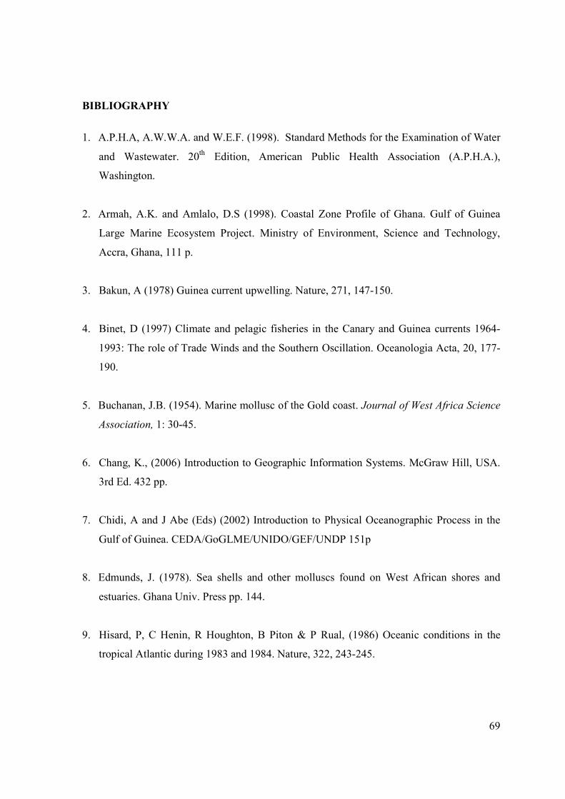
69
BIBLIOGRAPHY
1. A.P.H.A, A.W.W.A. and W.E.F. (1998). Standard Methods for the Examination of Water
and Wastewater. 20th Edition, American Public Health Association (A.P.H.A.),
Washington.
2. Armah, A.K. and Amlalo, D.S (1998). Coastal Zone Profile of Ghana. Gulf of Guinea
Large Marine Ecosystem Project. Ministry of Environment, Science and Technology,
Accra, Ghana, 111 p.
3. Bakun, A (1978) Guinea current upwelling. Nature, 271, 147-150.
4. Binet, D (1997) Climate and pelagic fisheries in the Canary and Guinea currents 1964-
1993: The role of Trade Winds and the Southern Oscillation. Oceanologia Acta, 20, 177-
190.
5. Buchanan, J.B. (1954). Marine mollusc of the Gold coast. Journal of West Africa Science
Association, 1: 30-45.
6. Chang, K., (2006) Introduction to Geographic Information Systems. McGraw Hill, USA.
3rd Ed. 432 pp.
7. Chidi, A and J Abe (Eds) (2002) Introduction to Physical Oceanographic Process in the
Gulf of Guinea. CEDA/GoGLME/UNIDO/GEF/UNDP 151p
8. Edmunds, J. (1978). Sea shells and other molluscs found on West African shores and
estuaries. Ghana Univ. Press pp. 144.
9. Hisard, P, C Henin, R Houghton, B Piton & P Rual, (1986) Oceanic conditions in the
tropical Atlantic during 1983 and 1984. Nature, 322, 243-245.
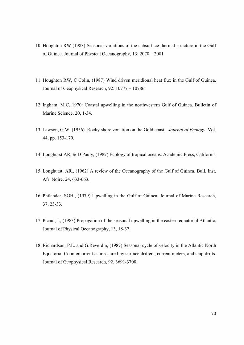
70
10. Houghton RW (1983) Seasonal variations of the subsurface thermal structure in the Gulf
of Guinea. Journal of Physical Oceanography, 13: 2070 – 2081
11. Houghton RW, C Colin, (1987) Wind driven meridional heat flux in the Gulf of Guinea.
Journal of Geophysical Research, 92: 10777 – 10786
12. Ingham, M.C, 1970: Coastal upwelling in the northwestern Gulf of Guinea. Bulletin of
Marine Science, 20, 1-34.
13. Lawson, G.W. (1956). Rocky shore zonation on the Gold coast. Journal of Ecology, Vol.
44, pp. 153-170.
14. Longhurst AR, & D Pauly, (1987) Ecology of tropical oceans. Academic Press, California
15. Longhurst, AR., (1962) A review of the Oceanography of the Gulf of Guinea. Bull. Inst.
Afr. Noire, 24, 633-663.
16. Philander, SGH., (1979) Upwelling in the Gulf of Guinea. Journal of Marine Research,
37, 23-33.
17. Picaut, I., (1983) Propagation of the seasonal upwelling in the eastern equatorial Atlantic.
Journal of Physical Oceanography, 13, 18-37.
18. Richardson, P.L. and G.Reverdin, (1987) Seasonal cycle of velocity in the Atlantic North
Equatorial Countercurrent as measured by surface drifters, current meters, and ship drifts.
Journal of Geophysical Research, 92, 3691-3708.
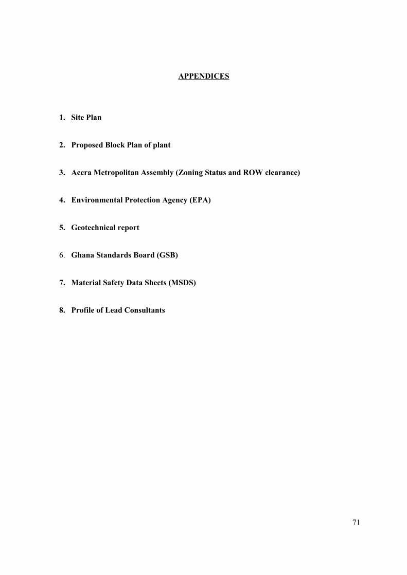
71
APPENDICES
1. Site Plan
2. Proposed Block Plan of plant
3. Accra Metropolitan Assembly (Zoning Status and ROW clearance)
4. Environmental Protection Agency (EPA)
5. Geotechnical report
6. Ghana Standards Board (GSB)
7. Material Safety Data Sheets (MSDS)
8. Profile of Lead Consultants

72
Appendix 1
Site Plan

73
Appendix 2
Proposed Block Plan of plant

74
Appendix 3
Accra Metropolitan Assembly (Zoning Status and ROW)

75
Appendix 4
Environmental Protection Agency (EPA)

76
Appendix 5
Geotechnical Report

77
Appendix 6
Ghana Standards Board (GSB)
78
26th March, 2011
The Executive Director
Ghana Standards Board
Head Office
Accra.
Dear Sir,
PROPOSED DESALINATION PLANT AT NUNGUA, ACCRA
Befesa Desalination Developments Ghana, (Befesa Ghana), plans to put up a reverse osmosis
desalination plant at Nungua in the Greater Accra Region to produce 60,000 m3/day of bulk
potable water from seawater for sale to Ghana Water Company Limited (GWCL). GWCL intends
to redistribute the potable water for public consumption.
As an important stakeholder, Befesa Ghana wishes to inform and solicit your written support for
the proposed project as part of requirements for Environmental Impact Assessment (EIA).
Many thanks.
Yours Sincerely,
Dr. F. K. E. Nunoo
Lead EIA Consultant
(Tel: +233 242 981547).

79
Appendix 7
Materials Safety Data Sheets

80
Appendix 8
Profile of Lead Consultants
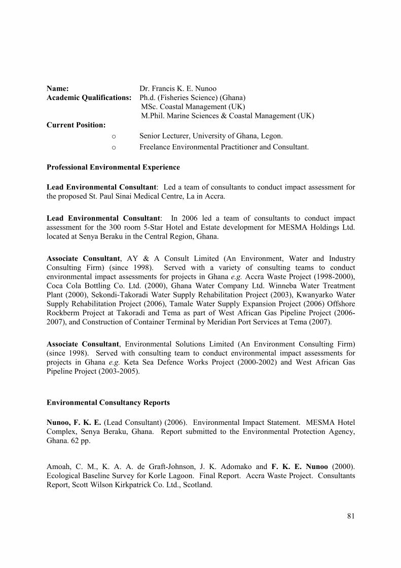
81
Name: Dr. Francis K. E. Nunoo Academic Qualifications: Ph.d. (Fisheries Science) (Ghana)
MSc. Coastal Management (UK) M.Phil. Marine Sciences & Coastal Management (UK)
Current Position:
o Senior Lecturer, University of Ghana, Legon.
o Freelance Environmental Practitioner and Consultant.
Professional Environmental Experience
Lead Environmental Consultant: Led a team of consultants to conduct impact assessment for the proposed St. Paul Sinai Medical Centre, La in Accra.
Lead Environmental Consultant: In 2006 led a team of consultants to conduct impact assessment for the 300 room 5-Star Hotel and Estate development for MESMA Holdings Ltd. located at Senya Beraku in the Central Region, Ghana.
Associate Consultant, AY & A Consult Limited (An Environment, Water and Industry Consulting Firm) (since 1998). Served with a variety of consulting teams to conduct environmental impact assessments for projects in Ghana e.g. Accra Waste Project (1998-2000), Coca Cola Bottling Co. Ltd. (2000), Ghana Water Company Ltd. Winneba Water Treatment Plant (2000), Sekondi-Takoradi Water Supply Rehabilitation Project (2003), Kwanyarko Water Supply Rehabilitation Project (2006), Tamale Water Supply Expansion Project (2006) Offshore Rockberm Project at Takoradi and Tema as part of West African Gas Pipeline Project (2006-2007), and Construction of Container Terminal by Meridian Port Services at Tema (2007).
Associate Consultant, Environmental Solutions Limited (An Environment Consulting Firm) (since 1998). Served with consulting team to conduct environmental impact assessments for projects in Ghana e.g. Keta Sea Defence Works Project (2000-2002) and West African Gas Pipeline Project (2003-2005).
Environmental Consultancy Reports
Nunoo, F. K. E. (Lead Consultant) (2006). Environmental Impact Statement. MESMA Hotel Complex, Senya Beraku, Ghana. Report submitted to the Environmental Protection Agency, Ghana. 62 pp.
Amoah, C. M., K. A. A. de Graft-Johnson, J. K. Adomako and F. K. E. Nunoo (2000). Ecological Baseline Survey for Korle Lagoon. Final Report. Accra Waste Project. Consultants Report, Scott Wilson Kirkpatrick Co. Ltd., Scotland.
82
Amoah, C. M., K. A. A. de Graft-Johnson, J. K. Adomako and F. K. E. Nunoo (1999). Ecological Baseline Survey for Korle Lagoon. Second Report. Accra Waste Project. Consultants Report, Scott Wilson Kirkpatrick Co. Ltd., Scotland.
Amoah, C. M., K. A. A. de Graft-Johnson, J. K. Adomako and F. K. E. Nunoo (1998). Ecological Baseline Survey for Korle Lagoon. First Report. Accra Waste Project. Consultants Report, Scott Wilson Kirkpatrick Co. Ltd., Scotland.
List of relevant Publications
Nunoo F. K. E. (1998). By-catch: A Problem of the Industrial Shrimp Fishery in Ghana. Journal
of the Ghana Science Association, 1:17-23.
Nunoo, F. K. E. (2001). A Simple Model for the Simultaneous Management of Seabird Populations and Discards at Sea. West African Journal of Applied Ecology 2: 83-89.
Nunoo, F. K. E. & Ebenezer Quayson (2003). Towards management of litter accumulation – case study of two beaches in Accra, Ghana. Journal of the Ghana Science Association, 5:145-
155.
Ajah, P.O. and F.K.E. Nunoo, (2003). The effects of four preservation methods on length, weight and condition factor of the clupeid Sardinella aurita Val. 1847. J. Appl. Ichthyol., 19: 391-
393.
Nunoo, F. K. E. & G. K. Ameka (2005). Occurrence of macro-algae in the by-catch of beach seine fisheries at Sakumono, Ghana. West African Journal of Applied Ecology 8: 79-87. Ahulu A. M, F. K. E. Nunoo and Erasmus H. Owusu (2006). Food preferences of the common tern Sterna hirundo, (Linnaeus, 1758) at the Densu floodplains, Accra. West African Journal of
Applied Ecology 9:141-148. Boateng, J. O., F. K. E. Nunoo, H. R. Dankwa and M. H. Ocran (2006). Acute Toxic Effects of Deltamethrin on Tilapia, Oreochromis niloticus (Linnaeus, 1758). West African Journal of
Applied Ecology 9:157-162.
Nunoo, F. K. E., D. B. Eggleston, & C. J. Vanderpuye (2006). Abundance, biomass and species composition of nearshore fish assemblages in Ghana, West Africa. African Journal of Marine
Science 28: 689-696.
Nunoo, F. K. E. & Stewart M. Evans (2007). Citizenship in a Ghanaian school: young people’s contributions to sustainable management of the coastal environment of West Africa. School Science Review 88 (324): 107-114.

83
Nunoo, F. K. E., S. Asem-Hiablie and D. O. Patu (2007). Trends in fish species diversity found in nearshore marine waters along the coast of Ghana, West Africa. Journal of the Ghana Science
Association 7: 10-19.
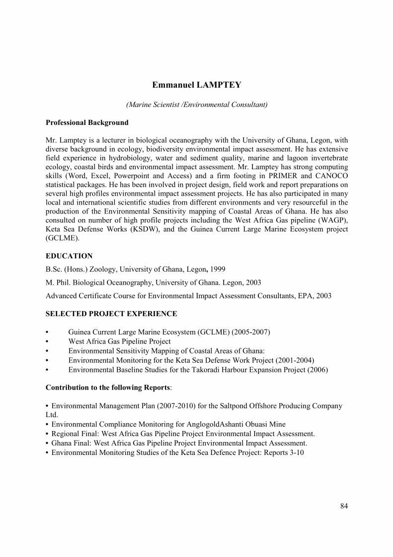
84
Emmanuel LAMPTEY
(Marine Scientist /Environmental Consultant)
Professional Background
Mr. Lamptey is a lecturer in biological oceanography with the University of Ghana, Legon, with diverse background in ecology, biodiversity environmental impact assessment. He has extensive field experience in hydrobiology, water and sediment quality, marine and lagoon invertebrate ecology, coastal birds and environmental impact assessment. Mr. Lamptey has strong computing skills (Word, Excel, Powerpoint and Access) and a firm footing in PRIMER and CANOCO statistical packages. He has been involved in project design, field work and report preparations on several high profiles environmental impact assessment projects. He has also participated in many local and international scientific studies from different environments and very resourceful in the production of the Environmental Sensitivity mapping of Coastal Areas of Ghana. He has also consulted on number of high profile projects including the West Africa Gas pipeline (WAGP), Keta Sea Defense Works (KSDW), and the Guinea Current Large Marine Ecosystem project (GCLME).
EDUCATION
B.Sc. (Hons.) Zoology, University of Ghana, Legon, 1999
M. Phil. Biological Oceanography, University of Ghana. Legon, 2003
Advanced Certificate Course for Environmental Impact Assessment Consultants, EPA, 2003
SELECTED PROJECT EXPERIENCE
• Guinea Current Large Marine Ecosystem (GCLME) (2005-2007)
• West Africa Gas Pipeline Project
• Environmental Sensitivity Mapping of Coastal Areas of Ghana:
• Environmental Monitoring for the Keta Sea Defense Work Project (2001-2004)
• Environmental Baseline Studies for the Takoradi Harbour Expansion Project (2006)
Contribution to the following Reports:
• Environmental Management Plan (2007-2010) for the Saltpond Offshore Producing Company Ltd.
• Environmental Compliance Monitoring for AnglogoldAshanti Obuasi Mine
• Regional Final: West Africa Gas Pipeline Project Environmental Impact Assessment.
• Ghana Final: West Africa Gas Pipeline Project Environmental Impact Assessment.
• Environmental Monitoring Studies of the Keta Sea Defence Project: Reports 3-10