proportional valve group - bibus.sk end plates pvs/pvsi ... © danfoss | january 2018...
TRANSCRIPT
Technical Information
Proportional Valve GroupPVG 16
powersolutions.danfoss.com
Revision history Table of revisions
Date Changed Rev
January 2018 Major update. 0601
July 2017 Major update. 0501
February 2017 Major update. 0401
March 2016 Minor update in PVHC technical characteristics 0303
March 2016 Updated to Engineering Tomorrow design. 0302
February 2016 Drawing was updated in topic: How to select the correct spool 0301
September 2015 PVG 16 Step II 0200
Feb. 2013-Mar. 2015 Major layout revision, drawings change BA-BF
October 2012 New Edition AA
Technical InformationPVG 16 Proportional Valve Group
2 | © Danfoss | January 2018 BC00000211en-US0601
General InformationGeneral Description.........................................................................................................................................................................5PVG 16 Features................................................................................................................................................................................ 5PVG 16 Modules Overview............................................................................................................................................................6
PVP Inlet ModulesOpen Center PVP.............................................................................................................................................................................. 8Open Center PVP with PPRV...................................................................................................................................................... 10Open center PVP with PPRV and adjustment spool..........................................................................................................13Closed Center PVP......................................................................................................................................................................... 16Closed Center PVP with PPRV....................................................................................................................................................18PVPX, Electrical LS Pressure Unloading Valve......................................................................................................................20
PVB Basic ModulesCompensated PVB......................................................................................................................................................................... 24Compensated PVB with PVLP/PVLA........................................................................................................................................27Compensated PVB with LS A/B................................................................................................................................................. 31Uncompensated PVB....................................................................................................................................................................34Uncompensated PVB with PVLP...............................................................................................................................................36PVLP, Shock/Anti-Cavitation and PVLA, Suction Valves...................................................................................................39
PVBS Main SpoolsElectric and/or Mechanical Actuation, Symmetrical PVBS Spools................................................................................43Electric and/or Mechanical Actuation, Asymmetrical PVBS Spools............................................................................. 46Hydraulic and/or Mechanical Actuation Symmetrical PVBS Spools............................................................................49Hydraulic and/or Mechanical Actuation, Asymmetrical PVBS Spools........................................................................ 51
PVG 16 ActuationPVM Manual Actuation................................................................................................................................................................ 54
PVMD Cover................................................................................................................................................................................56PVH Hydraulic Actuation.............................................................................................................................................................57PVHC Electro-Hydraulic Actuation...........................................................................................................................................59PVE Electrical Actuation...............................................................................................................................................................61PVEO – ON/OFF Voltage Control Actuator........................................................................................................................... 63
PVEO Technical Data............................................................................................................................................................... 65PVEA – Proportional Spool Control Actuator.......................................................................................................................66
PVEA Technical Data................................................................................................................................................................67PVG 16 Connector Variants........................................................................................................................................................ 69
Fault Monitoring and Fault ReactionGeneric Fault Reaction................................................................................................................................................................. 70Fault Reaction Overview..............................................................................................................................................................71
PVS End PlatesPVS/PVSI ........................................................................................................................................................................................... 73PVS/PVSI with LX-connection....................................................................................................................................................75PVSI with P-, T-, LX- and M-connection.................................................................................................................................. 77PVST with T-connection...............................................................................................................................................................79
PVAS Stay BoltsPVAS Part Numbers....................................................................................................................................................................... 82PVG 16 modules total length and weight.............................................................................................................................82PVG 32/16 Combinations............................................................................................................................................................ 83PVG 256/128/32/16 Combinations..........................................................................................................................................84
PVG 16 Combinations Valve Stack DimensionsPVG 16 Dimensions....................................................................................................................................................................... 86PVG 32/16 Dimensions.................................................................................................................................................................87PVG 100/16 Dimensions.............................................................................................................................................................. 89PVG 120/16 Dimensions.............................................................................................................................................................. 91PVG 128/16 Dimensions.............................................................................................................................................................. 93PVG 256/16 Dimensions.............................................................................................................................................................. 95
Technical InformationPVG 16 Proportional Valve Group
Contents
© Danfoss | January 2018 BC00000211en-US0601 | 3
PVG 16 Applications SchematicsPVG 16 Schematic with Basic End Plate................................................................................................................................. 97PVG 16 with P- and T-connection end plate........................................................................................................................ 98
Technical InformationPVG 16 Proportional Valve Group
Contents
4 | © Danfoss | January 2018 BC00000211en-US0601
General Description
PVG is a hydraulic, load-sensing proportional valve, designed for optimal machine performance andmaximum design flexibility. The PVG valve design is based on a modular concept that enables machinedesigners to specify a valve solution suitable for multiple market segments across multiple applications.
The PVG 16 is a member of the PVG product platform.
PVG 16 controls work port flow up to 65 l/min and up to 420 bar work port pressure.
The load independent proportional control valve and high performance actuator technology combinedwith a low pressure drop design improves the machine performance and efficiency – increasingproductivity and reducing energy consumption.
PVG 16 Features
PVG load-sensing proportional valves features and benefits summarized in a few bullets.• Inlet flow up to 140 l/min [37 US gal/min] 230 l/min [61 US gal/min] when used with mid-inlet
• Easy integration with PVG 32
• Possible combination with the rest of the PVG family: PVG 100, PVG 120 or PVG 128/256 when usingan interface module
• Up to 12 basic modules per PVG 16 valve group
• Load-independent flow control:
‒ Oil flow to an individual function is independent of the load pressure of this function
‒ Oil flow to one function is independent of the load pressure of other functions
• Reliable regulation characteristics across the entire flow range
• Load sense relief valves for A and B port enables reduced energy loss at target pressure
• Several options for connection threads and flange mount
• Compact design, easy installation and serviceability
Technical InformationPVG 16 Proportional Valve Group
General Information
© Danfoss | January 2018 BC00000211en-US0601 | 5
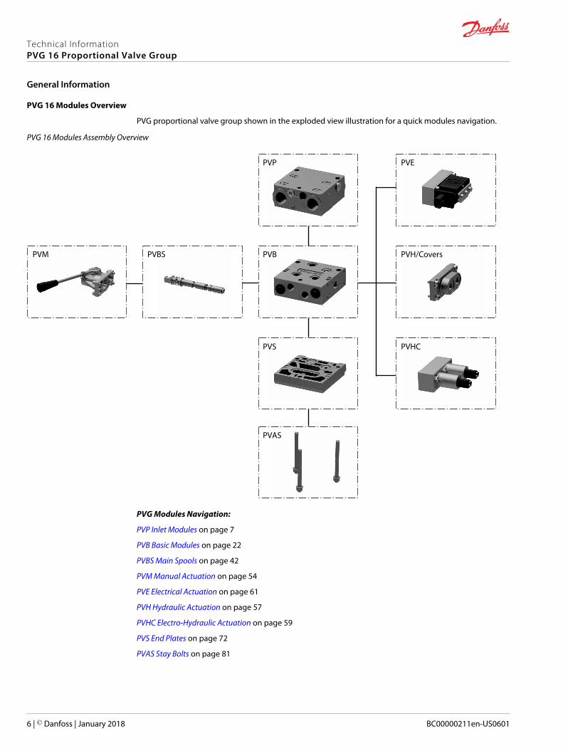
PVG 16 Modules Overview
PVG proportional valve group shown in the exploded view illustration for a quick modules navigation.
PVG 16 Modules Assembly Overview
PVM
PVP PVE
PVH/CoversPVBPVBS
PVS PVHC
PVAS
PVG Modules Navigation:
PVP Inlet Modules on page 7
PVB Basic Modules on page 22
PVBS Main Spools on page 42
PVM Manual Actuation on page 54
PVE Electrical Actuation on page 61
PVH Hydraulic Actuation on page 57
PVHC Electro-Hydraulic Actuation on page 59
PVS End Plates on page 72
PVAS Stay Bolts on page 81
Technical InformationPVG 16 Proportional Valve Group
General Information
6 | © Danfoss | January 2018 BC00000211en-US0601
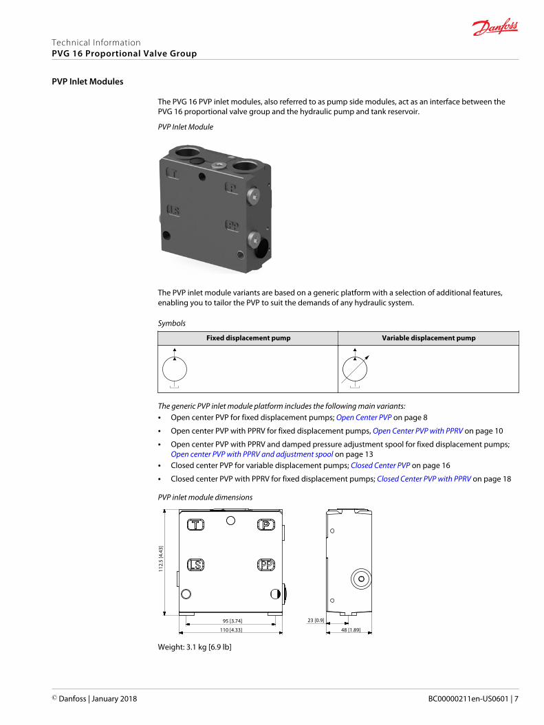
The PVG 16 PVP inlet modules, also referred to as pump side modules, act as an interface between thePVG 16 proportional valve group and the hydraulic pump and tank reservoir.
PVP Inlet Module
The PVP inlet module variants are based on a generic platform with a selection of additional features,enabling you to tailor the PVP to suit the demands of any hydraulic system.
Symbols
Fixed displacement pump Variable displacement pump
The generic PVP inlet module platform includes the following main variants:• Open center PVP for fixed displacement pumps; Open Center PVP on page 8
• Open center PVP with PPRV for fixed displacement pumps, Open Center PVP with PPRV on page 10
• Open center PVP with PPRV and damped pressure adjustment spool for fixed displacement pumps; Open center PVP with PPRV and adjustment spool on page 13
• Closed center PVP for variable displacement pumps; Closed Center PVP on page 16
• Closed center PVP with PPRV for fixed displacement pumps; Closed Center PVP with PPRV on page 18
PVP inlet module dimensions
112.
5 [4
.43]
110 [4.33]
95 [3.74] 23 [0.9]
48 [1.89]
Weight: 3.1 kg [6.9 lb]
Technical InformationPVG 16 Proportional Valve Group
PVP Inlet Modules
© Danfoss | January 2018 BC00000211en-US0601 | 7
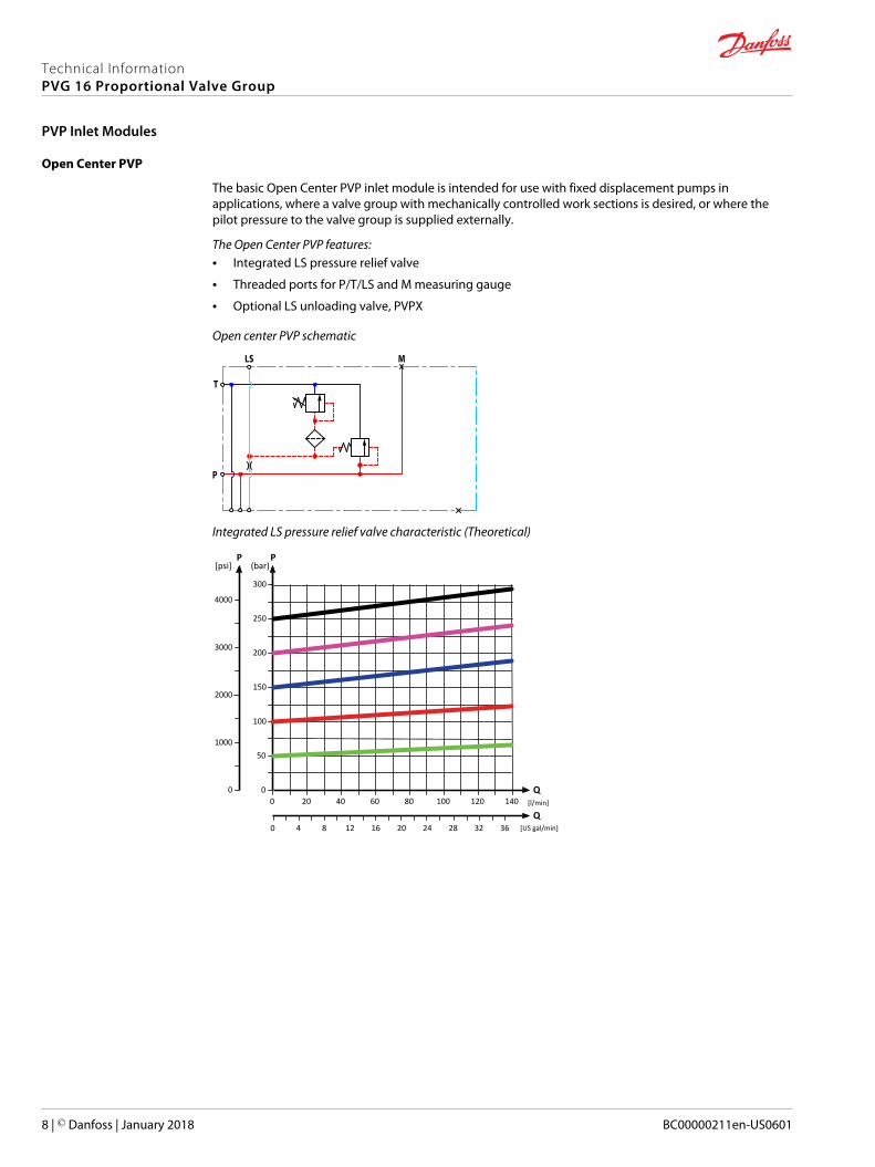
Open Center PVP
The basic Open Center PVP inlet module is intended for use with fixed displacement pumps inapplications, where a valve group with mechanically controlled work sections is desired, or where thepilot pressure to the valve group is supplied externally.
The Open Center PVP features:• Integrated LS pressure relief valve
• Threaded ports for P/T/LS and M measuring gauge
• Optional LS unloading valve, PVPX
Open center PVP schematic
LS
T
P
M
Integrated LS pressure relief valve characteristic (Theoretical)
[l/min]
[US gal/min]
200
150
100
50
20 40 60 80 100 120 140Q
300
250
PP
2000
1000
0 00
204 8 2824 32 3612 160
3000
4000
[psi]
Q
(bar)
Technical InformationPVG 16 Proportional Valve Group
PVP Inlet Modules
8 | © Danfoss | January 2018 BC00000211en-US0601
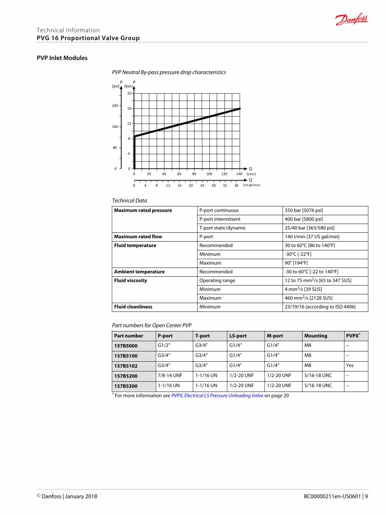
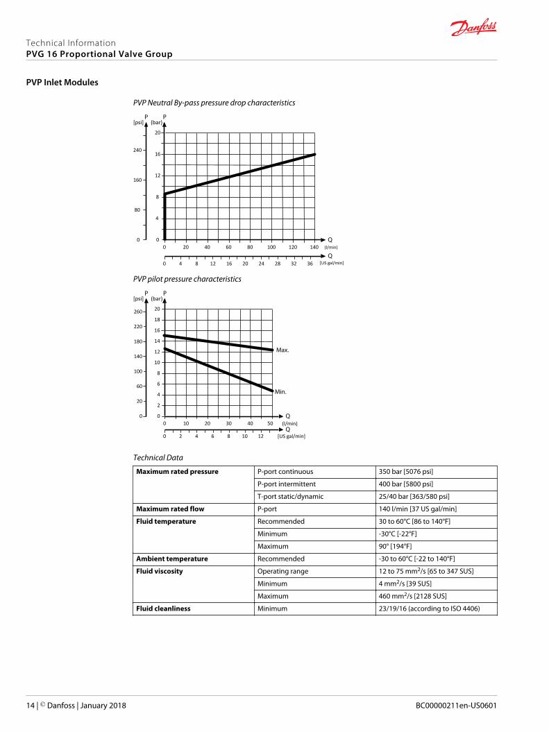
PVP Neutral By-pass pressure drop characteristics
(l/min)
[US gal/min]
20
20 40 60 80 100 120 140
16
12
8
4
160
80
0 00
240
[psi] (bar)
4 8 12 16 20 24 28 32 360
Technical Data
Maximum rated pressure P-port continuous 350 bar [5076 psi]
P-port intermittent 400 bar [5800 psi]
T-port static/dynamic 25/40 bar [363/580 psi]
Maximum rated flow P-port 140 l/min [37 US gal/min]
Fluid temperature Recommended 30 to 60°C [86 to 140°F]
Minimum -30°C [-22°F]
Maximum 90° [194°F]
Ambient temperature Recommended -30 to 60°C [-22 to 140°F]
Fluid viscosity Operating range 12 to 75 mm2/s [65 to 347 SUS]
Minimum 4 mm2/s [39 SUS]
Maximum 460 mm2/s [2128 SUS]
Fluid cleanliness Minimum 23/19/16 (according to ISO 4406)
Part numbers for Open Center PVP
Part number P-port T-port LS-port M-port Mounting PVPX*
157B5000 G1/2” G3/4” G1/4” G1/4” M8 –
157B5100 G3/4” G3/4” G1/4” G1/4” M8 –
157B5102 G3/4” G3/4” G1/4” G1/4” M8 Yes
157B5200 7/8-14 UNF 1-1/16 UN 1/2-20 UNF 1/2-20 UNF 5/16-18 UNC –
157B5300 1-1/16 UN 1-1/16 UN 1/2-20 UNF 1/2-20 UNF 5/16-18 UNC –
* For more information see PVPX, Electrical LS Pressure Unloading Valve on page 20
Technical InformationPVG 16 Proportional Valve Group
PVP Inlet Modules
© Danfoss | January 2018 BC00000211en-US0601 | 9

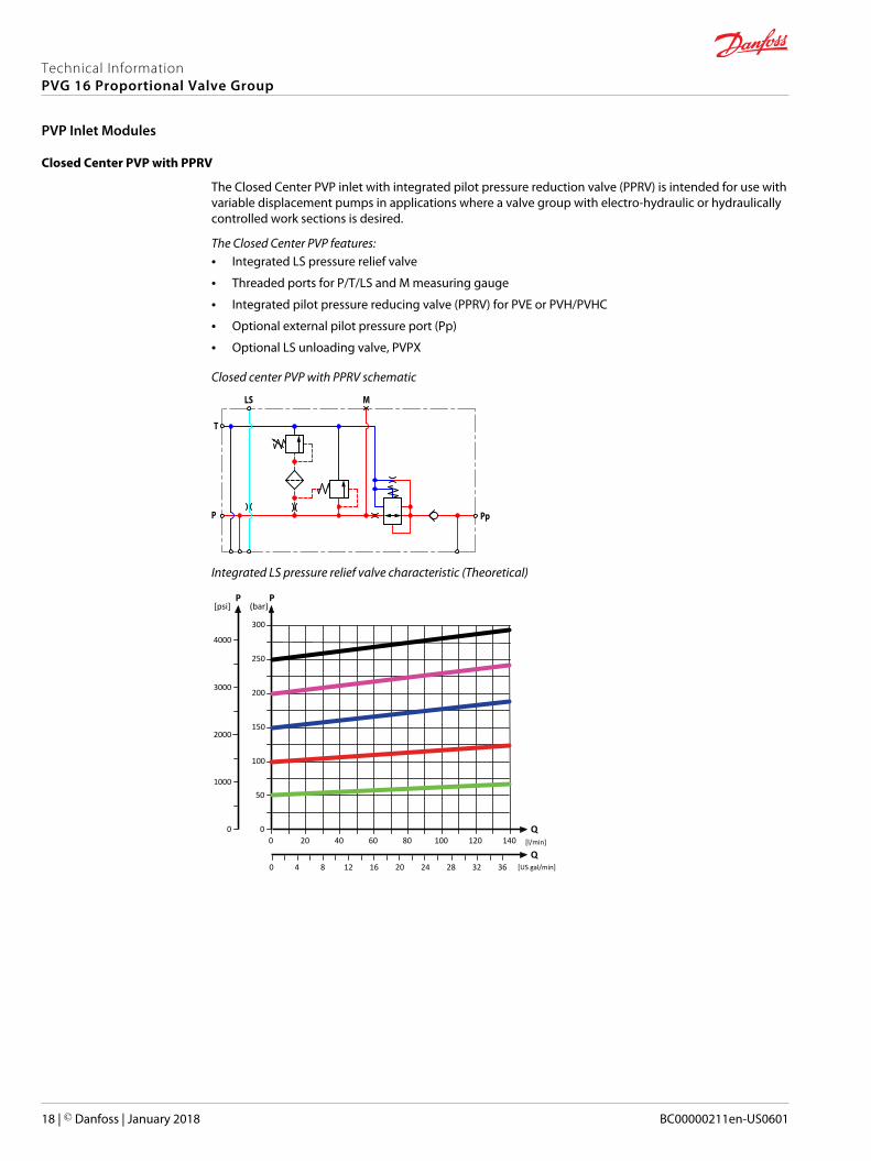
Open Center PVP with PPRV
The Open Center PVP inlet with integrated pilot pressure reduction valve (PPRV) is intended for use withfixed displacement pumps in applications, where a valve group with electro-hydraulically or hydraulicallycontrolled work sections is desired (PVE or PVH/PVHC).
The Open Center PVP features:• Integrated LS pressure relief valve
• Threaded ports for P/T/LS and M measuring gauge
• Integrated pilot pressure reducing valve (PPRV) for PVE or PVH/PVHC
• Optional external pilot pressure port (Pp)
• Optional LS unloading valve, PVPX
Open center PVP with PPRV schematic
Pp
LS
T
P
M
Integrated LS pressure relief valve characteristic (Theoretical)
[l/min]
[US gal/min]
200
150
100
50
20 40 60 80 100 120 140Q
300
250
PP
2000
1000
0 00
204 8 2824 32 3612 160
3000
4000
[psi]
Q
(bar)
Technical InformationPVG 16 Proportional Valve Group
PVP Inlet Modules
10 | © Danfoss | January 2018 BC00000211en-US0601
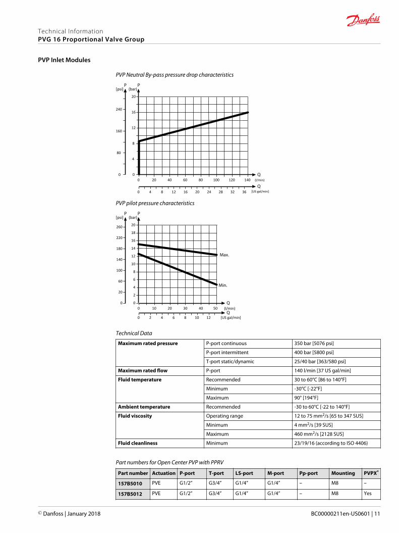
PVP Neutral By-pass pressure drop characteristics
(l/min)
[US gal/min]
20
20 40 60 80 100 120 140
16
12
8
4
160
80
0 00
240
[psi] (bar)
4 8 12 16 20 24 28 32 360
PVP pilot pressure characteristics
(l/min)
[US gal/min]
20
10 20 30 40 50
16
18
12
14
10
8
4
6
2
100
20
60
0 00
220
140
180
260
[psi] (bar)
6 122 4 8 100
Technical Data
Maximum rated pressure P-port continuous 350 bar [5076 psi]
P-port intermittent 400 bar [5800 psi]
T-port static/dynamic 25/40 bar [363/580 psi]
Maximum rated flow P-port 140 l/min [37 US gal/min]
Fluid temperature Recommended 30 to 60°C [86 to 140°F]
Minimum -30°C [-22°F]
Maximum 90° [194°F]
Ambient temperature Recommended -30 to 60°C [-22 to 140°F]
Fluid viscosity Operating range 12 to 75 mm2/s [65 to 347 SUS]
Minimum 4 mm2/s [39 SUS]
Maximum 460 mm2/s [2128 SUS]
Fluid cleanliness Minimum 23/19/16 (according to ISO 4406)
Part numbers for Open Center PVP with PPRV
Part number Actuation P-port T-port LS-port M-port Pp-port Mounting PVPX*
157B5010 PVE G1/2” G3/4” G1/4” G1/4” – M8 –
157B5012 PVE G1/2” G3/4” G1/4” G1/4” – M8 Yes
Technical InformationPVG 16 Proportional Valve Group
PVP Inlet Modules
© Danfoss | January 2018 BC00000211en-US0601 | 11
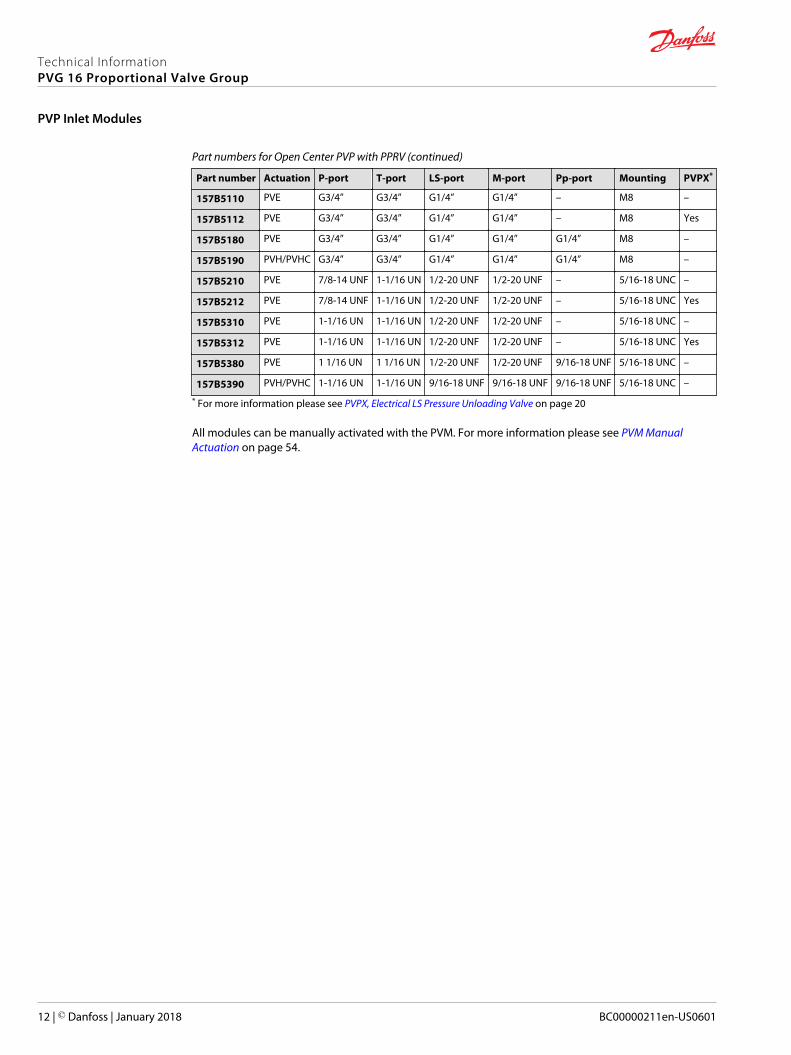
Part numbers for Open Center PVP with PPRV (continued)
Part number Actuation P-port T-port LS-port M-port Pp-port Mounting PVPX*
157B5110 PVE G3/4” G3/4” G1/4” G1/4” – M8 –
157B5112 PVE G3/4” G3/4” G1/4” G1/4” – M8 Yes
157B5180 PVE G3/4” G3/4” G1/4” G1/4” G1/4” M8 –
157B5190 PVH/PVHC G3/4” G3/4” G1/4” G1/4” G1/4” M8 –
157B5210 PVE 7/8-14 UNF 1-1/16 UN 1/2-20 UNF 1/2-20 UNF – 5/16-18 UNC –
157B5212 PVE 7/8-14 UNF 1-1/16 UN 1/2-20 UNF 1/2-20 UNF – 5/16-18 UNC Yes
157B5310 PVE 1-1/16 UN 1-1/16 UN 1/2-20 UNF 1/2-20 UNF – 5/16-18 UNC –
157B5312 PVE 1-1/16 UN 1-1/16 UN 1/2-20 UNF 1/2-20 UNF – 5/16-18 UNC Yes
157B5380 PVE 1 1/16 UN 1 1/16 UN 1/2-20 UNF 1/2-20 UNF 9/16-18 UNF 5/16-18 UNC –
157B5390 PVH/PVHC 1-1/16 UN 1-1/16 UN 9/16-18 UNF 9/16-18 UNF 9/16-18 UNF 5/16-18 UNC –
* For more information please see PVPX, Electrical LS Pressure Unloading Valve on page 20
All modules can be manually activated with the PVM. For more information please see PVM ManualActuation on page 54.
Technical InformationPVG 16 Proportional Valve Group
PVP Inlet Modules
12 | © Danfoss | January 2018 BC00000211en-US0601
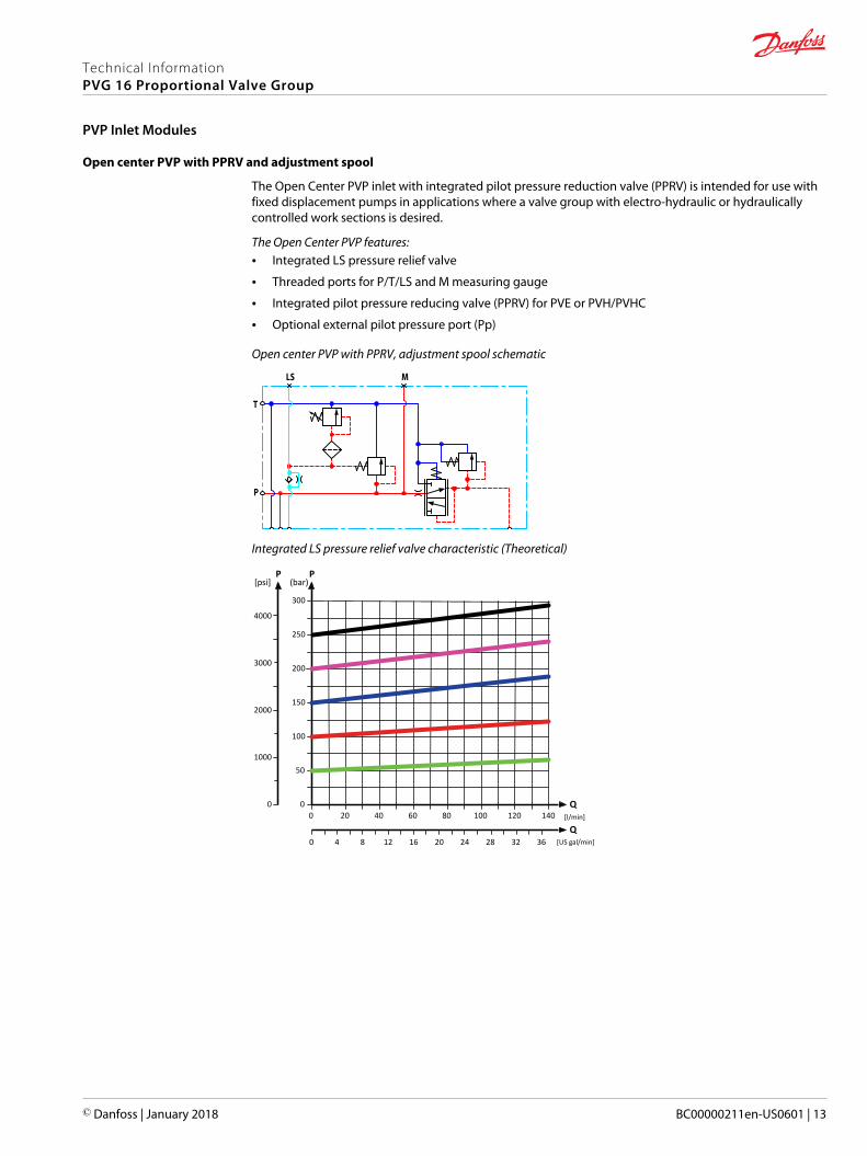
Open center PVP with PPRV and adjustment spool
The Open Center PVP inlet with integrated pilot pressure reduction valve (PPRV) is intended for use withfixed displacement pumps in applications where a valve group with electro-hydraulic or hydraulicallycontrolled work sections is desired.
The Open Center PVP features:• Integrated LS pressure relief valve
• Threaded ports for P/T/LS and M measuring gauge
• Integrated pilot pressure reducing valve (PPRV) for PVE or PVH/PVHC
• Optional external pilot pressure port (Pp)
Open center PVP with PPRV, adjustment spool schematic
LS
T
P
M
Integrated LS pressure relief valve characteristic (Theoretical)
[l/min]
[US gal/min]
200
150
100
50
20 40 60 80 100 120 140Q
300
250
PP
2000
1000
0 00
204 8 2824 32 3612 160
3000
4000
[psi]
Q
(bar)
Technical InformationPVG 16 Proportional Valve Group
PVP Inlet Modules
© Danfoss | January 2018 BC00000211en-US0601 | 13
PVP Neutral By-pass pressure drop characteristics
(l/min)
[US gal/min]
20
20 40 60 80 100 120 140
16
12
8
4
160
80
0 00
240
[psi] (bar)
4 8 12 16 20 24 28 32 360
PVP pilot pressure characteristics
(l/min)
[US gal/min]
20
10 20 30 40 50
16
18
12
14
10
8
4
6
2
100
20
60
0 00
220
140
180
260
[psi] (bar)
6 122 4 8 100
Technical Data
Maximum rated pressure P-port continuous 350 bar [5076 psi]
P-port intermittent 400 bar [5800 psi]
T-port static/dynamic 25/40 bar [363/580 psi]
Maximum rated flow P-port 140 l/min [37 US gal/min]
Fluid temperature Recommended 30 to 60°C [86 to 140°F]
Minimum -30°C [-22°F]
Maximum 90° [194°F]
Ambient temperature Recommended -30 to 60°C [-22 to 140°F]
Fluid viscosity Operating range 12 to 75 mm2/s [65 to 347 SUS]
Minimum 4 mm2/s [39 SUS]
Maximum 460 mm2/s [2128 SUS]
Fluid cleanliness Minimum 23/19/16 (according to ISO 4406)
Technical InformationPVG 16 Proportional Valve Group
PVP Inlet Modules
14 | © Danfoss | January 2018 BC00000211en-US0601
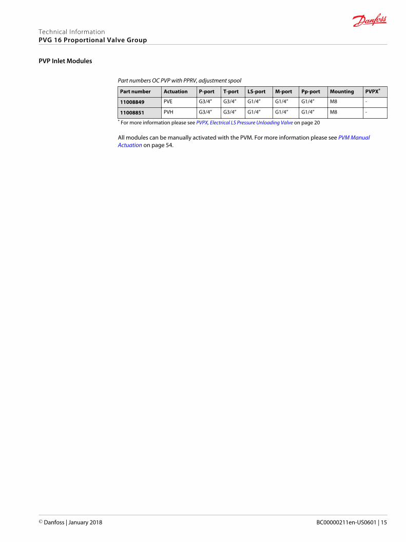
Part numbers OC PVP with PPRV, adjustment spool
Part number Actuation P-port T-port LS-port M-port Pp-port Mounting PVPX*
11008849 PVE G3/4” G3/4” G1/4” G1/4” G1/4” M8 -
11008851 PVH G3/4” G3/4” G1/4” G1/4” G1/4” M8 -
* For more information please see PVPX, Electrical LS Pressure Unloading Valve on page 20
All modules can be manually activated with the PVM. For more information please see PVM ManualActuation on page 54.
Technical InformationPVG 16 Proportional Valve Group
PVP Inlet Modules
© Danfoss | January 2018 BC00000211en-US0601 | 15
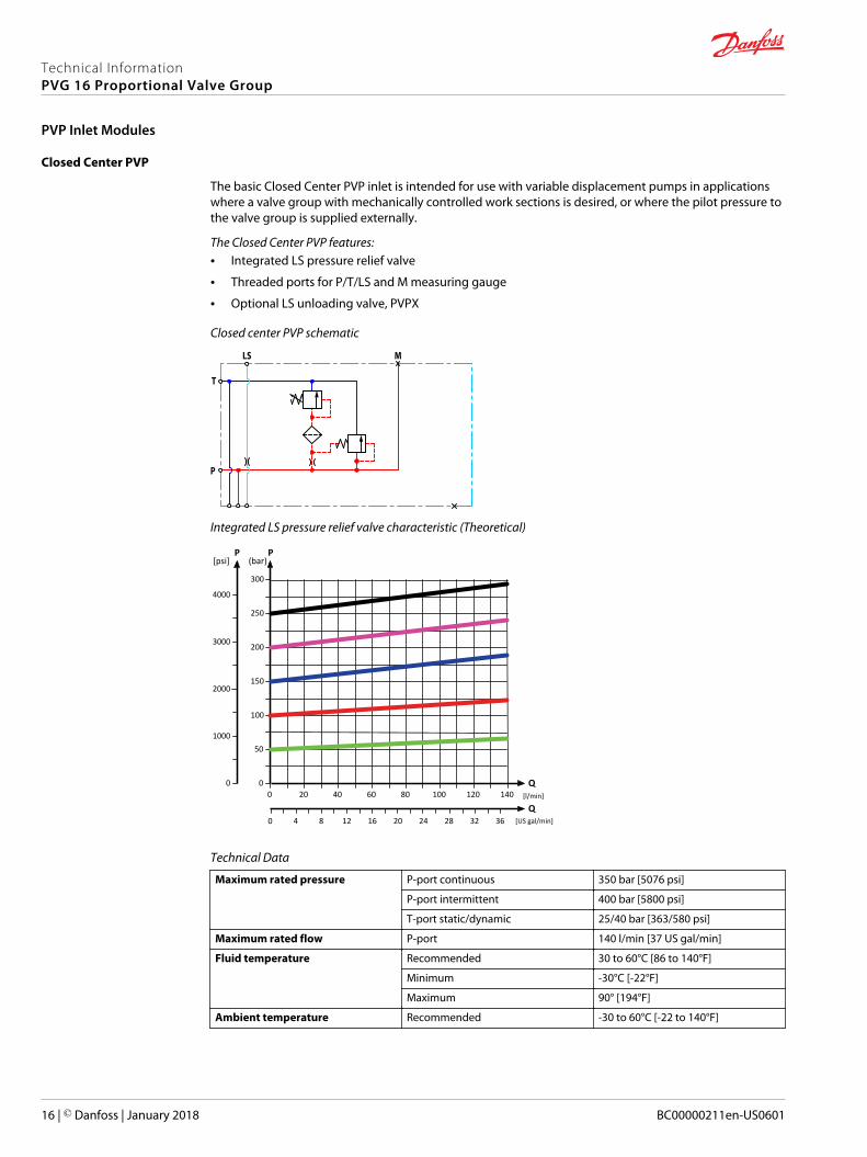
Closed Center PVP
The basic Closed Center PVP inlet is intended for use with variable displacement pumps in applicationswhere a valve group with mechanically controlled work sections is desired, or where the pilot pressure tothe valve group is supplied externally.
The Closed Center PVP features:• Integrated LS pressure relief valve
• Threaded ports for P/T/LS and M measuring gauge
• Optional LS unloading valve, PVPX
Closed center PVP schematic
LS
T
P
M
Integrated LS pressure relief valve characteristic (Theoretical)
[l/min]
[US gal/min]
200
150
100
50
20 40 60 80 100 120 140Q
300
250
PP
2000
1000
0 00
204 8 2824 32 3612 160
3000
4000
[psi]
Q
(bar)
Technical Data
Maximum rated pressure P-port continuous 350 bar [5076 psi]
P-port intermittent 400 bar [5800 psi]
T-port static/dynamic 25/40 bar [363/580 psi]
Maximum rated flow P-port 140 l/min [37 US gal/min]
Fluid temperature Recommended 30 to 60°C [86 to 140°F]
Minimum -30°C [-22°F]
Maximum 90° [194°F]
Ambient temperature Recommended -30 to 60°C [-22 to 140°F]
Technical InformationPVG 16 Proportional Valve Group
PVP Inlet Modules
16 | © Danfoss | January 2018 BC00000211en-US0601
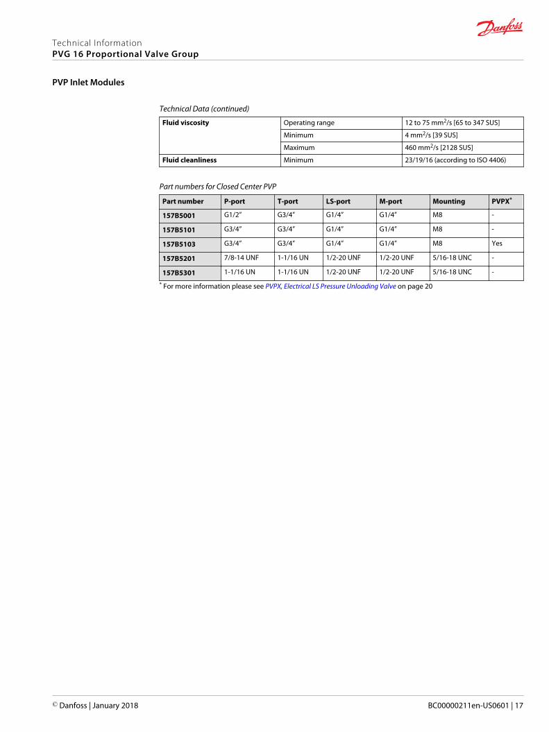
Technical Data (continued)
Fluid viscosity Operating range 12 to 75 mm2/s [65 to 347 SUS]
Minimum 4 mm2/s [39 SUS]
Maximum 460 mm2/s [2128 SUS]
Fluid cleanliness Minimum 23/19/16 (according to ISO 4406)
Part numbers for Closed Center PVP
Part number P-port T-port LS-port M-port Mounting PVPX*
157B5001 G1/2” G3/4” G1/4” G1/4” M8 -
157B5101 G3/4” G3/4” G1/4” G1/4” M8 -
157B5103 G3/4” G3/4” G1/4” G1/4” M8 Yes
157B5201 7/8-14 UNF 1-1/16 UN 1/2-20 UNF 1/2-20 UNF 5/16-18 UNC -
157B5301 1-1/16 UN 1-1/16 UN 1/2-20 UNF 1/2-20 UNF 5/16-18 UNC -
* For more information please see PVPX, Electrical LS Pressure Unloading Valve on page 20
Technical InformationPVG 16 Proportional Valve Group
PVP Inlet Modules
© Danfoss | January 2018 BC00000211en-US0601 | 17
Closed Center PVP with PPRV
The Closed Center PVP inlet with integrated pilot pressure reduction valve (PPRV) is intended for use withvariable displacement pumps in applications where a valve group with electro-hydraulic or hydraulicallycontrolled work sections is desired.
The Closed Center PVP features:• Integrated LS pressure relief valve
• Threaded ports for P/T/LS and M measuring gauge
• Integrated pilot pressure reducing valve (PPRV) for PVE or PVH/PVHC
• Optional external pilot pressure port (Pp)
• Optional LS unloading valve, PVPX
Closed center PVP with PPRV schematic
Pp
LS
T
P
M
Integrated LS pressure relief valve characteristic (Theoretical)
[l/min]
[US gal/min]
200
150
100
50
20 40 60 80 100 120 140Q
300
250
PP
2000
1000
0 00
204 8 2824 32 3612 160
3000
4000
[psi]
Q
(bar)
Technical InformationPVG 16 Proportional Valve Group
PVP Inlet Modules
18 | © Danfoss | January 2018 BC00000211en-US0601
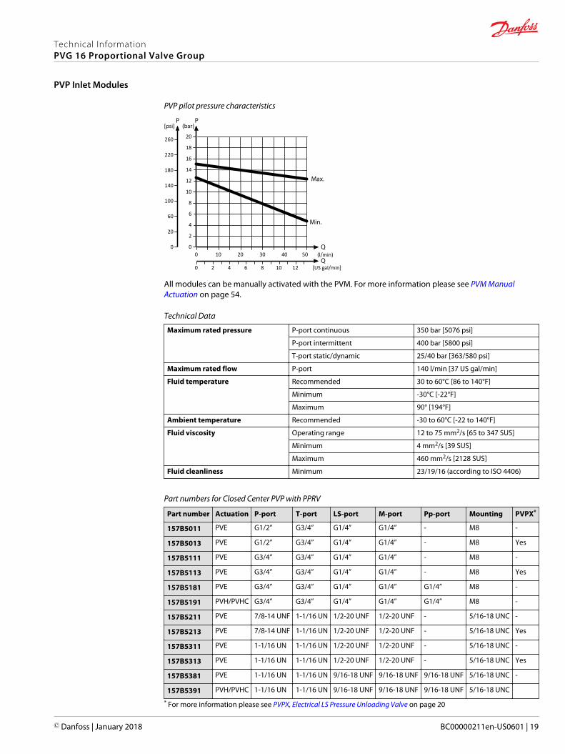
PVP pilot pressure characteristics
(l/min)
[US gal/min]
20
10 20 30 40 50
16
18
12
14
10
8
4
6
2
100
20
60
0 00
220
140
180
260
[psi] (bar)
6 122 4 8 100
All modules can be manually activated with the PVM. For more information please see PVM ManualActuation on page 54.
Technical Data
Maximum rated pressure P-port continuous 350 bar [5076 psi]
P-port intermittent 400 bar [5800 psi]
T-port static/dynamic 25/40 bar [363/580 psi]
Maximum rated flow P-port 140 l/min [37 US gal/min]
Fluid temperature Recommended 30 to 60°C [86 to 140°F]
Minimum -30°C [-22°F]
Maximum 90° [194°F]
Ambient temperature Recommended -30 to 60°C [-22 to 140°F]
Fluid viscosity Operating range 12 to 75 mm2/s [65 to 347 SUS]
Minimum 4 mm2/s [39 SUS]
Maximum 460 mm2/s [2128 SUS]
Fluid cleanliness Minimum 23/19/16 (according to ISO 4406)
Part numbers for Closed Center PVP with PPRV
Part number Actuation P-port T-port LS-port M-port Pp-port Mounting PVPX*
157B5011 PVE G1/2” G3/4” G1/4” G1/4” - M8 -
157B5013 PVE G1/2” G3/4” G1/4” G1/4” - M8 Yes
157B5111 PVE G3/4” G3/4” G1/4” G1/4” - M8 -
157B5113 PVE G3/4” G3/4” G1/4” G1/4” - M8 Yes
157B5181 PVE G3/4” G3/4” G1/4” G1/4” G1/4” M8 -
157B5191 PVH/PVHC G3/4” G3/4” G1/4” G1/4” G1/4” M8 -
157B5211 PVE 7/8-14 UNF 1-1/16 UN 1/2-20 UNF 1/2-20 UNF - 5/16-18 UNC -
157B5213 PVE 7/8-14 UNF 1-1/16 UN 1/2-20 UNF 1/2-20 UNF - 5/16-18 UNC Yes
157B5311 PVE 1-1/16 UN 1-1/16 UN 1/2-20 UNF 1/2-20 UNF - 5/16-18 UNC -
157B5313 PVE 1-1/16 UN 1-1/16 UN 1/2-20 UNF 1/2-20 UNF - 5/16-18 UNC Yes
157B5381 PVE 1-1/16 UN 1-1/16 UN 9/16-18 UNF 9/16-18 UNF 9/16-18 UNF 5/16-18 UNC -
157B5391 PVH/PVHC 1-1/16 UN 1-1/16 UN 9/16-18 UNF 9/16-18 UNF 9/16-18 UNF 5/16-18 UNC
* For more information please see PVPX, Electrical LS Pressure Unloading Valve on page 20
Technical InformationPVG 16 Proportional Valve Group
PVP Inlet Modules
© Danfoss | January 2018 BC00000211en-US0601 | 19
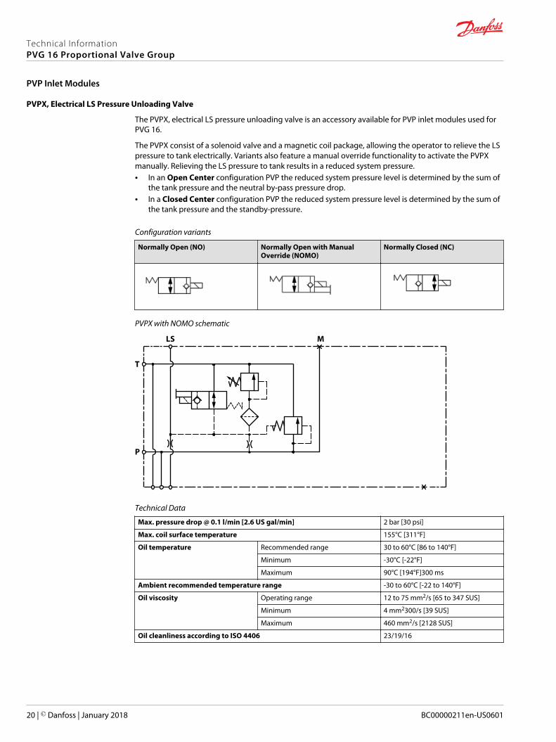
PVPX, Electrical LS Pressure Unloading Valve
The PVPX, electrical LS pressure unloading valve is an accessory available for PVP inlet modules used forPVG 16.
The PVPX consist of a solenoid valve and a magnetic coil package, allowing the operator to relieve the LSpressure to tank electrically. Variants also feature a manual override functionality to activate the PVPXmanually. Relieving the LS pressure to tank results in a reduced system pressure.• In an Open Center configuration PVP the reduced system pressure level is determined by the sum of
the tank pressure and the neutral by-pass pressure drop.• In a Closed Center configuration PVP the reduced system pressure level is determined by the sum of
the tank pressure and the standby-pressure.
Configuration variants
Normally Open (NO) Normally Open with ManualOverride (NOMO)
Normally Closed (NC)
PVPX with NOMO schematic
P
T
MLS
Technical Data
Max. pressure drop @ 0.1 l/min [2.6 US gal/min] 2 bar [30 psi]
Max. coil surface temperature 155°C [311°F]
Oil temperature Recommended range 30 to 60°C [86 to 140°F]
Minimum -30°C [-22°F]
Maximum 90°C [194°F]300 ms
Ambient recommended temperature range -30 to 60°C [-22 to 140°F]
Oil viscosity Operating range 12 to 75 mm2/s [65 to 347 SUS]
Minimum 4 mm2300/s [39 SUS]
Maximum 460 mm2/s [2128 SUS]
Oil cleanliness according to ISO 4406 23/19/16
Technical InformationPVG 16 Proportional Valve Group
PVP Inlet Modules
20 | © Danfoss | January 2018 BC00000211en-US0601
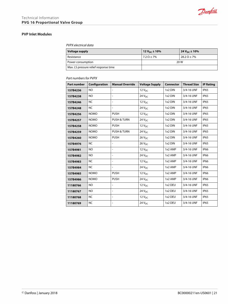
PVPX electrical data
Voltage supply 12 VDC ± 10% 24 VDC ± 10%
Resistance 7.2 Ω ± 7% 28.2 Ω ± 7%
Power consumption 20 W
Max. LS pressure relief response time
Part numbers for PVPX
Part number Configuration Manual Override Voltage Supply Connector Thread Size IP Rating
157B4236 NO - 12 VDC 1x2 DIN 3/4-16 UNF IP65
157B4238 NO - 24 VDC 1x2 DIN 3/4-16 UNF IP65
157B4246 NC - 12 VDC 1x2 DIN 3/4-16 UNF IP65
157B4248 NC - 24 VDC 1x2 DIN 3/4-16 UNF IP65
157B4256 NOMO PUSH 12 VDC 1x2 DIN 3/4-16 UNF IP65
157B4257 NOMO PUSH & TURN 24 VDC 1x2 DIN 3/4-16 UNF IP65
157B4258 NOMO PUSH 12 VDC 1x2 DIN 3/4-16 UNF IP65
157B4259 NOMO PUSH & TURN 24 VDC 1x2 DIN 3/4-16 UNF IP65
157B4260 NOMO PUSH 26 VDC 1x2 DIN 3/4-16 UNF IP65
157B4976 NC - 26 VDC 1x2 DIN 3/4-16 UNF IP65
157B4981 NO - 12 VDC 1x2 AMP 3/4-16 UNF IP66
157B4982 NO - 24 VDC 1x2 AMP 3/4-16 UNF IP66
157B4983 NC - 12 VDC 1x2 AMP 3/4-16 UNF IP66
157B4984 NC - 24 VDC 1x2 AMP 3/4-16 UNF IP66
157B4985 NOMO PUSH 12 VDC 1x2 AMP 3/4-16 UNF IP66
157B4986 NOMO PUSH 24 VDC 1x2 AMP 3/4-16 UNF IP66
11180766 NO - 12 VDC 1x2 DEU 3/4-16 UNF IP65
11180767 NO - 24 VDC 1x2 DEU 3/4-16 UNF IP65
11180768 NC - 12 VDC 1x2 DEU 3/4-16 UNF IP65
11180769 NC - 24 VDC 1x2 DEU 3/4-16 UNF IP65
Technical InformationPVG 16 Proportional Valve Group
PVP Inlet Modules
© Danfoss | January 2018 BC00000211en-US0601 | 21
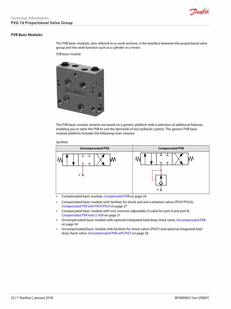
The PVB basic modules, also referred to as work sections, is the interface between the proportional valvegroup and the work function such as a cylinder or a motor.
PVB basic module
The PVB basic module variants are based on a generic platform with a selection of additional features,enabling you to tailor the PVB to suit the demands of any hydraulic system. The generic PVB basicmodule platform includes the following main variants:
Symbols
Uncompensated PVB Compensated PVB
P
P
• Compensated basic module; Compensated PVB on page 24
• Compensated basic module with facilities for shock and anti-cavitation valves (PVLP/PVLA); Compensated PVB with PVLP/PVLA on page 27
• Compensated basic module with one common adjustable LS valve for port A and port B; Compensated PVB with LS A/B on page 31
• Uncompensated basic module with optional integrated load drop check valve; Uncompensated PVBon page 34
• Uncompensated basic module with facilities for shock valves (PVLP) and optional integrated loaddrop check valve; Uncompensated PVB with PVLP on page 36
Technical InformationPVG 16 Proportional Valve Group
PVB Basic Modules
22 | © Danfoss | January 2018 BC00000211en-US0601
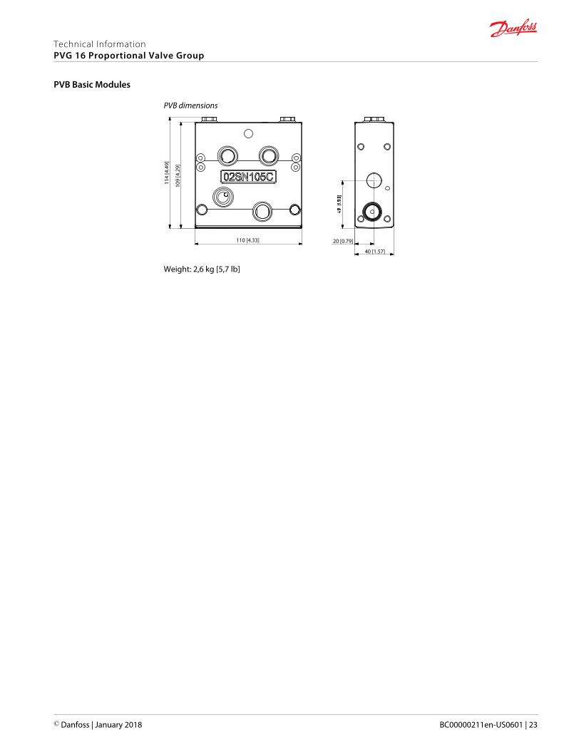
PVB dimensions
114
[4.4
9]
109
[4.2
9]
110 [4.33] 20 [0.79]
40 [1.57]
Weight: 2,6 kg [5,7 lb]
Technical InformationPVG 16 Proportional Valve Group
PVB Basic Modules
© Danfoss | January 2018 BC00000211en-US0601 | 23
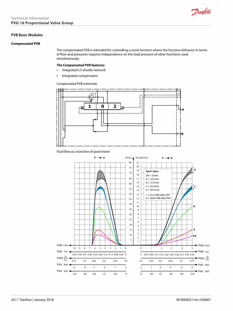
Compensated PVB
The compensated PVB is intended for controlling a work function where the function behavior in termsof flow and pressures requires independence on the load pressure of other functions usedsimultaneously.
The Compensated PVB features:• Integrated LS shuttle network
• Integrated compensator
Compensated PVB schematic
1 0 2
B
A
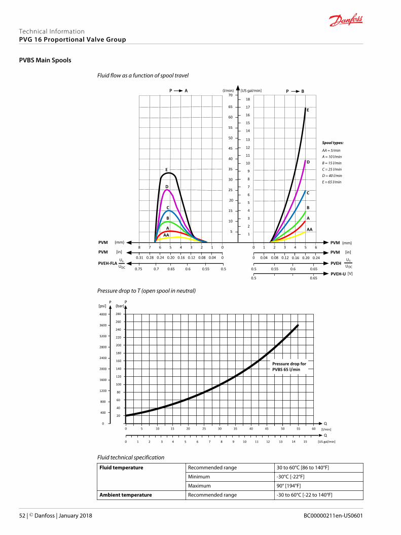
Fluid flow as a function of spool travel
AP
5
10
15
20
25
30
35
40
45
50
55
60
65
(l/min) [US gal/min]
PVM (mm)0
0
1234567PVM [in]
0.28 0.24 0.20 0.16 0.12 0.08 0.04
PVEA0.50.550.60.650.7
8
0.31
0.75
910
70
75
80
0.39 0.35
1
2
3
4
5
6
7
8
9
10
11
12
13
14
15
16
17
18
19
20
21
BP
PVM543
PVM0.20 0.24 0.28 0.31 0.35 0.39
PVEA0.70.650.60.55
2
0.16
0.5
10
0 0.04 0.08 0.12
0.75
PVHPVH (bar)
AA
B
C
D
A
579111315 1311975 15
PVH73218
PVH73 218
[psi]189 160 131 102 102 131 160 189
Us
UDC
Us
UDC
1
1
6
6
Spool types:
A = 10 l/minB = 15 l/min
AA = 5/min
C = 25 l/minD = 40 l/min
1 = First PVB after PVP6 = Sixth PVB after PVP
(mm)
[in]
(bar)
[psi]
Technical InformationPVG 16 Proportional Valve Group
PVB Basic Modules
24 | © Danfoss | January 2018 BC00000211en-US0601
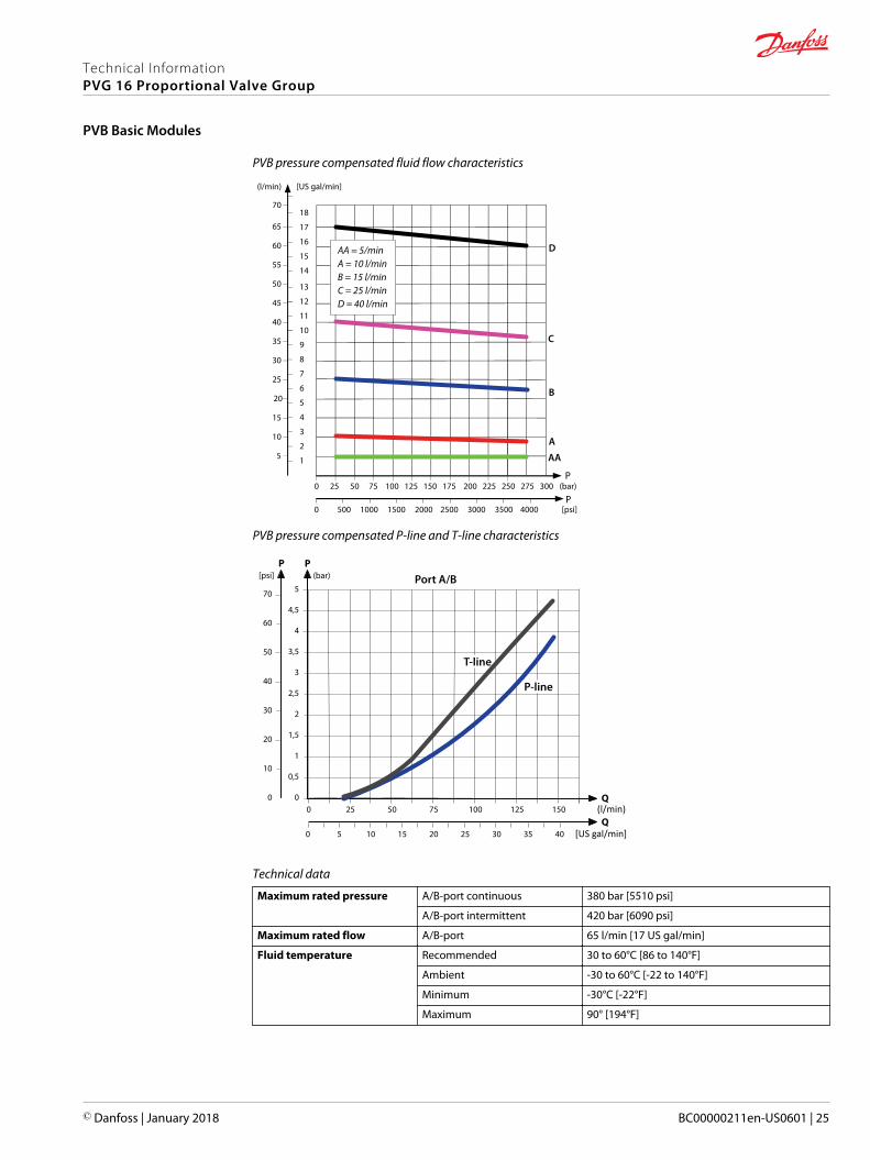
PVB pressure compensated fluid flow characteristics
5
10
15
20
25
30
35
40
45
50
55
60
65
(l/min) [US gal/min]
70
1
2
3
4
5
6
7
8
9
10
11
12
13
14
15
16
17
18
0 25 50 75 100 125 150 175 200 225 250 275 300
0 500 1000 1500 2000 2500 3000 3500 4000
P
AA
B
C
D
A
P(bar)
[psi]
A = 10 l/minB = 15 l/min
AA = 5/min
C = 25 l/minD = 40 l/min
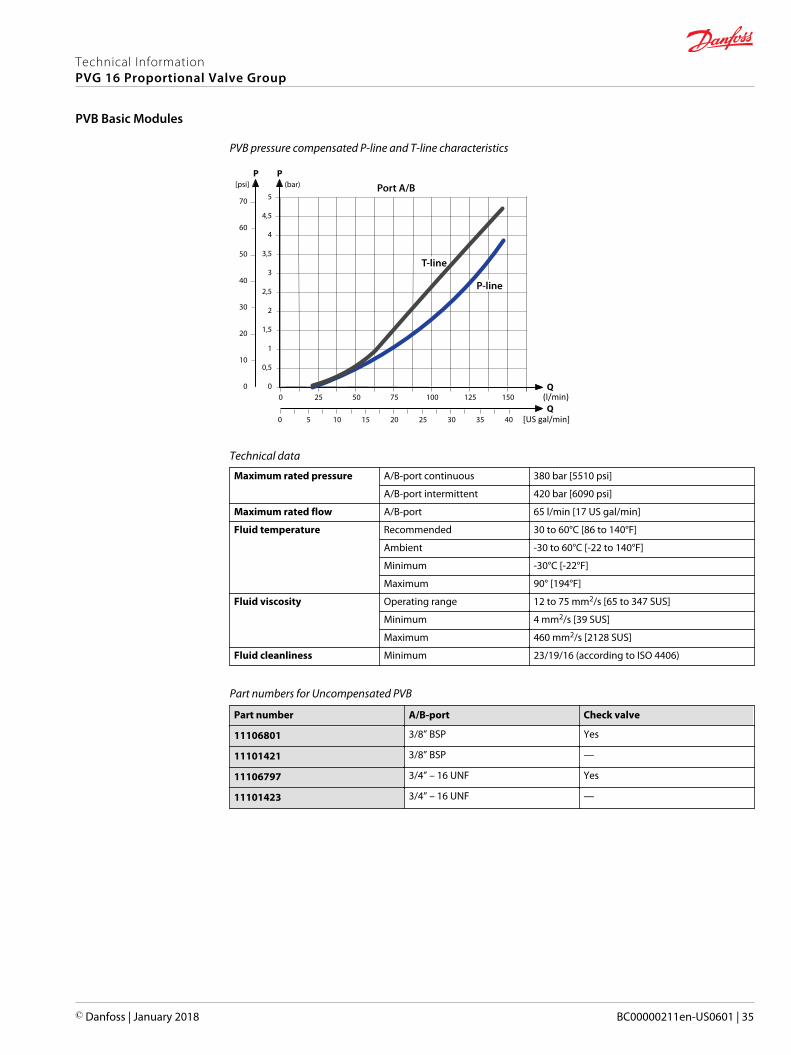
PVB pressure compensated P-line and T-line characteristics
Q
Q
P[psi]
(l/min)
[US gal/min]
5
4,5
4
3,5
3
2,5
2
1,5
1
0,5
0
50
50
40
30
20
10
0
70
7525
5 10 15 20 25 30 35 40
100 125 150
60
0
0
Port A/B
T-line
P-line
P(bar)
Technical data
Maximum rated pressure A/B-port continuous 380 bar [5510 psi]
A/B-port intermittent 420 bar [6090 psi]
Maximum rated flow A/B-port 65 l/min [17 US gal/min]
Fluid temperature Recommended 30 to 60°C [86 to 140°F]
Ambient -30 to 60°C [-22 to 140°F]
Minimum -30°C [-22°F]
Maximum 90° [194°F]
Technical InformationPVG 16 Proportional Valve Group
PVB Basic Modules
© Danfoss | January 2018 BC00000211en-US0601 | 25

Technical data (continued)
Fluid viscosity Operating range 12 to 75 mm2/s [65 to 347 SUS]
Minimum 4 mm2/s [39 SUS]
Maximum 460 mm2/s [2128 SUS]
Fluid cleanliness Minimum 23/19/16 (according to ISO 4406)
Part numbers for Compensated PVB
Part number A/B-port
11130976 3/8” BSP
11130977 3/4” – 16 UNF
Technical InformationPVG 16 Proportional Valve Group
PVB Basic Modules
26 | © Danfoss | January 2018 BC00000211en-US0601
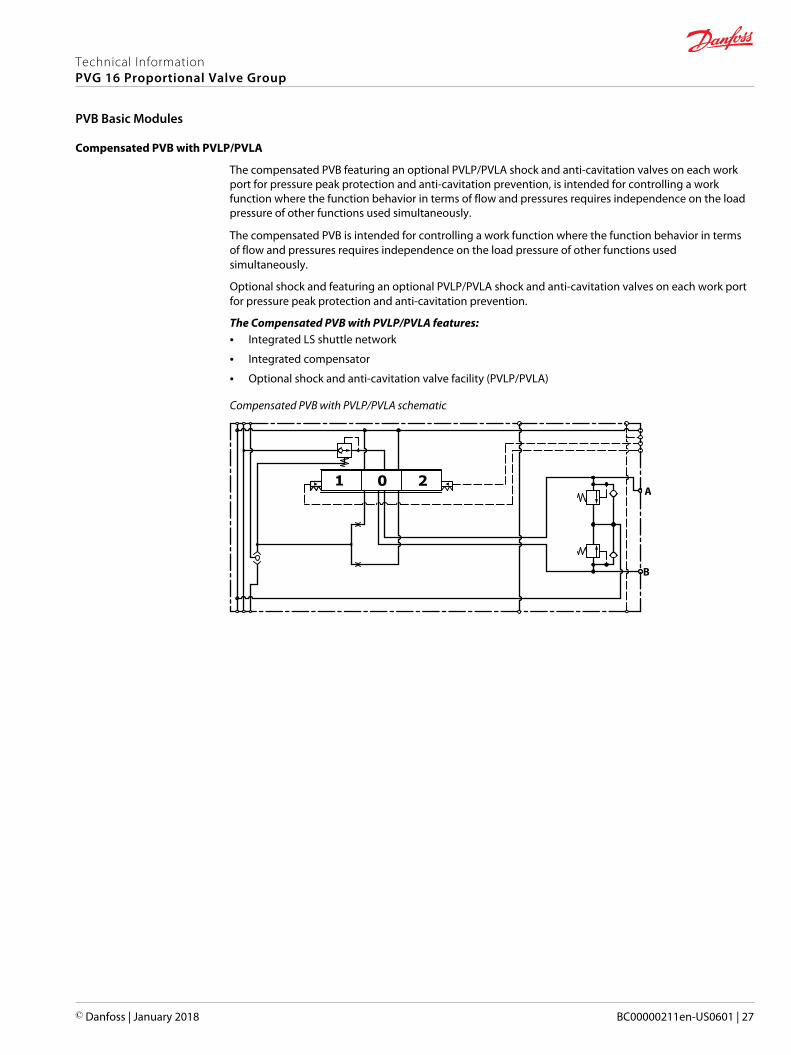
Compensated PVB with PVLP/PVLA
The compensated PVB featuring an optional PVLP/PVLA shock and anti-cavitation valves on each workport for pressure peak protection and anti-cavitation prevention, is intended for controlling a workfunction where the function behavior in terms of flow and pressures requires independence on the loadpressure of other functions used simultaneously.
The compensated PVB is intended for controlling a work function where the function behavior in termsof flow and pressures requires independence on the load pressure of other functions usedsimultaneously.
Optional shock and featuring an optional PVLP/PVLA shock and anti-cavitation valves on each work portfor pressure peak protection and anti-cavitation prevention.
The Compensated PVB with PVLP/PVLA features:• Integrated LS shuttle network
• Integrated compensator
• Optional shock and anti-cavitation valve facility (PVLP/PVLA)
Compensated PVB with PVLP/PVLA schematic
1 0 2
B
A
Technical InformationPVG 16 Proportional Valve Group
PVB Basic Modules
© Danfoss | January 2018 BC00000211en-US0601 | 27
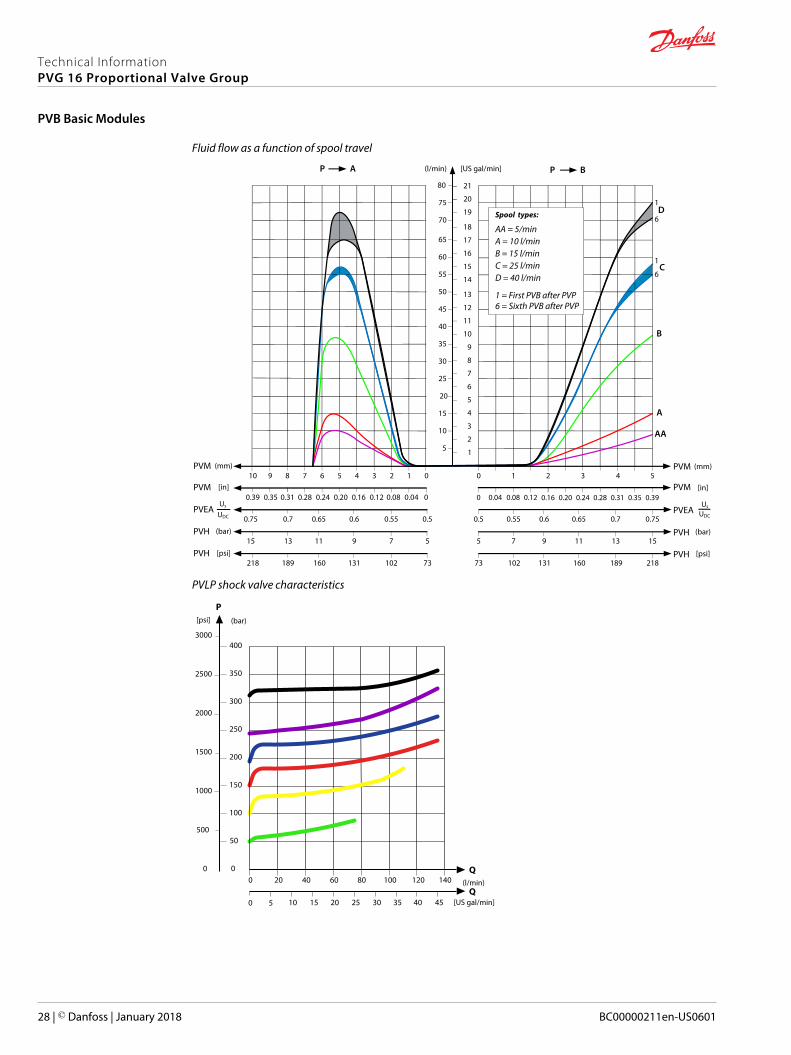
Fluid flow as a function of spool travel
AP
5
10
15
20
25
30
35
40
45
50
55
60
65
(l/min) [US gal/min]
PVM (mm)0
0
1234567PVM [in]
0.28 0.24 0.20 0.16 0.12 0.08 0.04
PVEA0.50.550.60.650.7
8
0.31
0.75
910
70
75
80
0.39 0.35
1
2
3
4
5
6
7
8
9
10
11
12
13
14
15
16
17
18
19
20
21
BP
PVM543
PVM0.20 0.24 0.28 0.31 0.35 0.39
PVEA0.70.650.60.55
2
0.16
0.5
10
0 0.04 0.08 0.12
0.75
PVHPVH (bar)
AA
B
C
D
A
579111315 1311975 15
PVH73218
PVH73 218
[psi]189 160 131 102 102 131 160 189
Us
UDC
Us
UDC
1
1
6
6
Spool types:
A = 10 l/minB = 15 l/min
AA = 5/min
C = 25 l/minD = 40 l/min
1 = First PVB after PVP6 = Sixth PVB after PVP
(mm)
[in]
(bar)
[psi]
PVLP shock valve characteristics
(l/min)
[US gal/min]
P
Q
Q
(bar)[psi]
20 40 60 80 100 120 140
5 10 15 20 25 30 35 40 45
400
350
300
250
200
150
100
50
0
2500
2000
1500
1000
500
0
3000
0
0
Technical InformationPVG 16 Proportional Valve Group
PVB Basic Modules
28 | © Danfoss | January 2018 BC00000211en-US0601
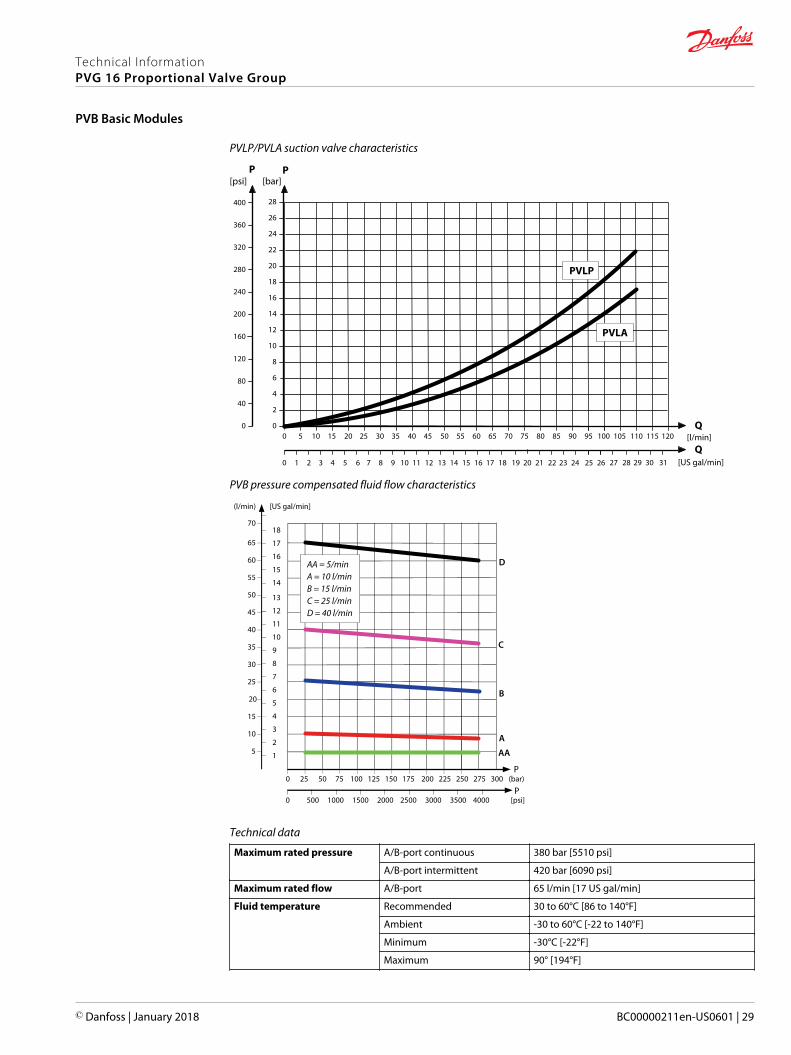
PVLP/PVLA suction valve characteristics
5 10 15 20 25 30 35 40 45 50 55 60 65 [l/min]
[US gal/min]
70 75 80
1 2 3 4 5 6 7 8 9 10 11 12 13 14 15 16 17 18 19 20 21
20
18
16
14
12
10
8
6
4
2
085 90 95 100
22 23 24 25 26
Q
28
26
24
22
PP
200
160
120
80
40
0
280
240
320
400
360
0
[psi] [bar]
0
Q105 110 115 120
27 28 29 30 31
PVLP
PVLA
PVB pressure compensated fluid flow characteristics
5
10
15
20
25
30
35
40
45
50
55
60
65
(l/min) [US gal/min]
70
1
2
3
4
5
6
7
8
9
10
11
12
13
14
15
16
17
18
0 25 50 75 100 125 150 175 200 225 250 275 300
0 500 1000 1500 2000 2500 3000 3500 4000
P
AA
B
C
D
A
P(bar)
[psi]
A = 10 l/minB = 15 l/min
AA = 5/min
C = 25 l/minD = 40 l/min
Technical data
Maximum rated pressure A/B-port continuous 380 bar [5510 psi]
A/B-port intermittent 420 bar [6090 psi]
Maximum rated flow A/B-port 65 l/min [17 US gal/min]
Fluid temperature Recommended 30 to 60°C [86 to 140°F]
Ambient -30 to 60°C [-22 to 140°F]
Minimum -30°C [-22°F]
Maximum 90° [194°F]
Technical InformationPVG 16 Proportional Valve Group
PVB Basic Modules
© Danfoss | January 2018 BC00000211en-US0601 | 29
Technical data (continued)
Fluid viscosity Operating range 12 to 75 mm2/s [65 to 347 SUS]
Minimum 4 mm2/s [39 SUS]
Maximum 460 mm2/s [2128 SUS]
Fluid cleanliness Minimum 23/19/16 (according to ISO 4406)
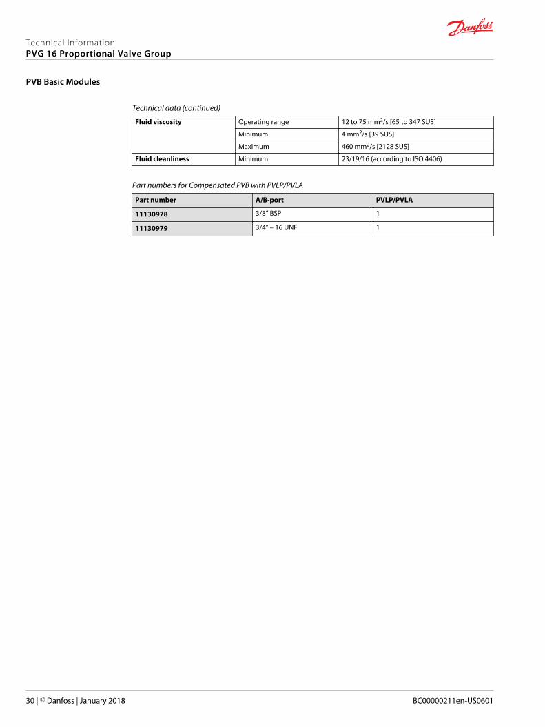
Part numbers for Compensated PVB with PVLP/PVLA
Part number A/B-port PVLP/PVLA
11130978 3/8” BSP 1
11130979 3/4” – 16 UNF 1
Technical InformationPVG 16 Proportional Valve Group
PVB Basic Modules
30 | © Danfoss | January 2018 BC00000211en-US0601
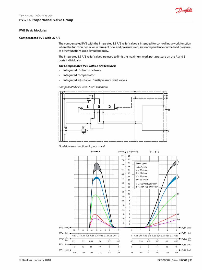
Compensated PVB with LS A/B
The compensated PVB with the integrated LS A/B relief valves is intended for controlling a work functionwhere the function behavior in terms of flow and pressures requires independence on the load pressureof other functions used simultaneously.
The integrated LS A/B relief valves are used to limit the maximum work port pressure on the A and Bports individually.
The Compensated PVB with LS A/B features:• Integrated LS shuttle network
• Integrated compensator
• Integrated adjustable LS A/B pressure relief valves
Compensated PVB with LS A/B schematic
1 0 2
B
A
Fluid flow as a function of spool travel
AP
5
10
15
20
25
30
35
40
45
50
55
60
65
(l/min) [US gal/min]
PVM (mm)0
0
1234567PVM [in]
0.28 0.24 0.20 0.16 0.12 0.08 0.04
PVEA0.50.550.60.650.7
8
0.31
0.75
910
70
75
80
0.39 0.35
1
2
3
4
5
6
7
8
9
10
11
12
13
14
15
16
17
18
19
20
21
BP
PVM543
PVM0.20 0.24 0.28 0.31 0.35 0.39
PVEA0.70.650.60.55
2
0.16
0.5
10
0 0.04 0.08 0.12
0.75
PVHPVH (bar)
AA
B
C
D
A
579111315 1311975 15
PVH73218
PVH73 218
[psi]189 160 131 102 102 131 160 189
Us
UDC
Us
UDC
1
1
6
6
Spool types:
A = 10 l/minB = 15 l/min
AA = 5/min
C = 25 l/minD = 40 l/min
1 = First PVB after PVP6 = Sixth PVB after PVP
(mm)
[in]
(bar)
[psi]
Technical InformationPVG 16 Proportional Valve Group
PVB Basic Modules
© Danfoss | January 2018 BC00000211en-US0601 | 31
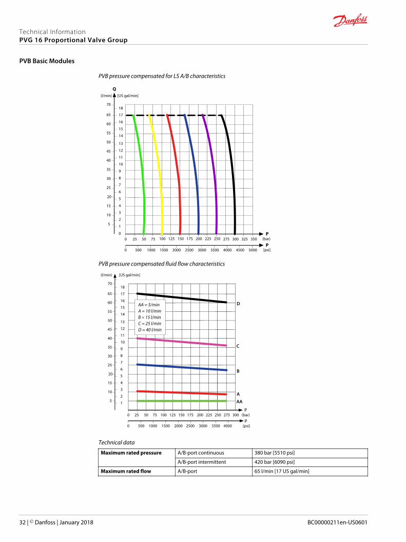
PVB pressure compensated for LS A/B characteristics
(l/min) [US gal/min]
P
Q
P(bar)
[psi]
5
10
15
20
25
30
35
40
45
50
55
60
65
70
1
2
3
4
5
6
7
8
9
10
11
12
13
14
15
16
17
18
2502252001751501251007550250 350325300275
25002000150010005000 35003000 4000 50004500
0
PVB pressure compensated fluid flow characteristics
5
10
15
20
25
30
35
40
45
50
55
60
65
(l/min) [US gal/min]
70
1
2
3
4
5
6
7
8
9
10
11
12
13
14
15
16
17
18
0 25 50 75 100 125 150 175 200 225 250 275 300
0 500 1000 1500 2000 2500 3000 3500 4000
P
AA
B
C
D
A
P(bar)
[psi]
A = 10 l/minB = 15 l/min
AA = 5/min
C = 25 l/minD = 40 l/min
Technical data
Maximum rated pressure A/B-port continuous 380 bar [5510 psi]
A/B-port intermittent 420 bar [6090 psi]
Maximum rated flow A/B-port 65 l/min [17 US gal/min]
Technical InformationPVG 16 Proportional Valve Group
PVB Basic Modules
32 | © Danfoss | January 2018 BC00000211en-US0601
Technical data (continued)
Fluid temperature Recommended 30 to 60°C [86 to 140°F]
Ambient -30 to 60°C [-22 to 140°F]
Minimum -30°C [-22°F]
Maximum 90° [194°F]
Fluid viscosity Operating range 12 to 75 mm2/s [65 to 347 SUS]
Minimum 4 mm2/s [39 SUS]
Maximum 460 mm2/s [2128 SUS]
Fluid cleanliness Minimum 23/19/16 (according to ISO 4406)
Part numbers for Compensated PVB with LS A/B
Part number A/B-port
11130982 3/8” BSP
11130983 3/4” – 16 UNF
Technical InformationPVG 16 Proportional Valve Group
PVB Basic Modules
© Danfoss | January 2018 BC00000211en-US0601 | 33
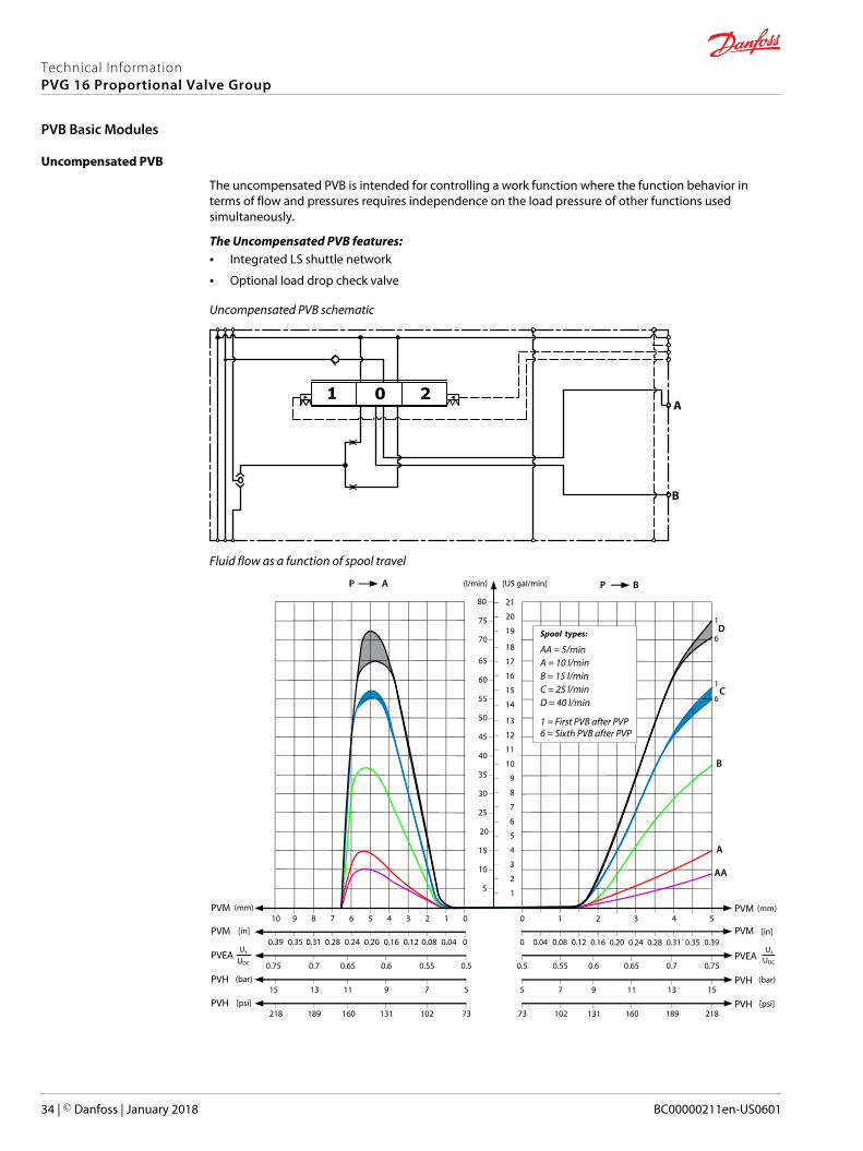
Uncompensated PVB
The uncompensated PVB is intended for controlling a work function where the function behavior interms of flow and pressures requires independence on the load pressure of other functions usedsimultaneously.
The Uncompensated PVB features:• Integrated LS shuttle network
• Optional load drop check valve
Uncompensated PVB schematic
1 0 2
B
A
Fluid flow as a function of spool travel
AP
5
10
15
20
25
30
35
40
45
50
55
60
65
(l/min) [US gal/min]
PVM (mm)0
0
1234567PVM [in]
0.28 0.24 0.20 0.16 0.12 0.08 0.04
PVEA0.50.550.60.650.7
8
0.31
0.75
910
70
75
80
0.39 0.35
1
2
3
4
5
6
7
8
9
10
11
12
13
14
15
16
17
18
19
20
21
BP
PVM543
PVM0.20 0.24 0.28 0.31 0.35 0.39
PVEA0.70.650.60.55
2
0.16
0.5
10
0 0.04 0.08 0.12
0.75
PVHPVH (bar)
AA
B
C
D
A
579111315 1311975 15
PVH73218
PVH73 218
[psi]189 160 131 102 102 131 160 189
Us
UDC
Us
UDC
1
1
6
6
Spool types:
A = 10 l/minB = 15 l/min
AA = 5/min
C = 25 l/minD = 40 l/min
1 = First PVB after PVP6 = Sixth PVB after PVP
(mm)
[in]
(bar)
[psi]
Technical InformationPVG 16 Proportional Valve Group
PVB Basic Modules
34 | © Danfoss | January 2018 BC00000211en-US0601
PVB pressure compensated P-line and T-line characteristics
Q
Q
P[psi]
(l/min)
[US gal/min]
5
4,5
4
3,5
3
2,5
2
1,5
1
0,5
0
50
50
40
30
20
10
0
70
7525
5 10 15 20 25 30 35 40
100 125 150
60
0
0
Port A/B
T-line
P-line
P(bar)
Technical data
Maximum rated pressure A/B-port continuous 380 bar [5510 psi]
A/B-port intermittent 420 bar [6090 psi]
Maximum rated flow A/B-port 65 l/min [17 US gal/min]
Fluid temperature Recommended 30 to 60°C [86 to 140°F]
Ambient -30 to 60°C [-22 to 140°F]
Minimum -30°C [-22°F]
Maximum 90° [194°F]
Fluid viscosity Operating range 12 to 75 mm2/s [65 to 347 SUS]
Minimum 4 mm2/s [39 SUS]
Maximum 460 mm2/s [2128 SUS]
Fluid cleanliness Minimum 23/19/16 (according to ISO 4406)
Part numbers for Uncompensated PVB
Part number A/B-port Check valve
11106801 3/8” BSP Yes
11101421 3/8” BSP —
11106797 3/4” – 16 UNF Yes
11101423 3/4” – 16 UNF —
Technical InformationPVG 16 Proportional Valve Group
PVB Basic Modules
© Danfoss | January 2018 BC00000211en-US0601 | 35
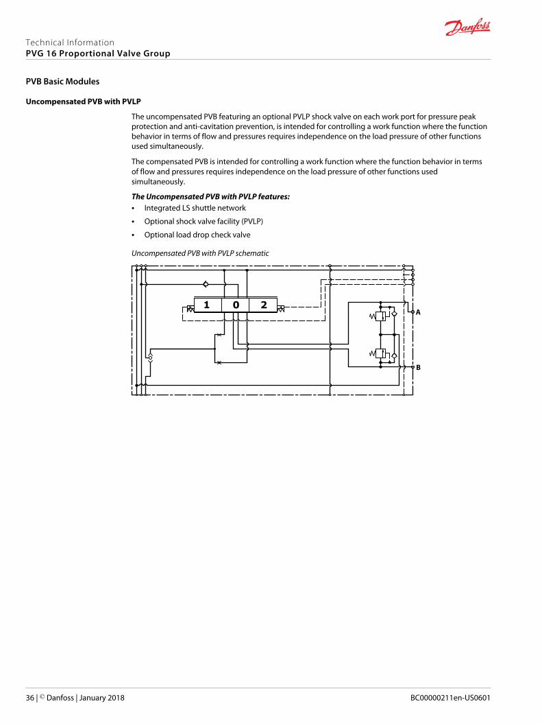
Uncompensated PVB with PVLP
The uncompensated PVB featuring an optional PVLP shock valve on each work port for pressure peakprotection and anti-cavitation prevention, is intended for controlling a work function where the functionbehavior in terms of flow and pressures requires independence on the load pressure of other functionsused simultaneously.
The compensated PVB is intended for controlling a work function where the function behavior in termsof flow and pressures requires independence on the load pressure of other functions usedsimultaneously.
The Uncompensated PVB with PVLP features:• Integrated LS shuttle network
• Optional shock valve facility (PVLP)
• Optional load drop check valve
Uncompensated PVB with PVLP schematic
1 0 2
B
A
Technical InformationPVG 16 Proportional Valve Group
PVB Basic Modules
36 | © Danfoss | January 2018 BC00000211en-US0601
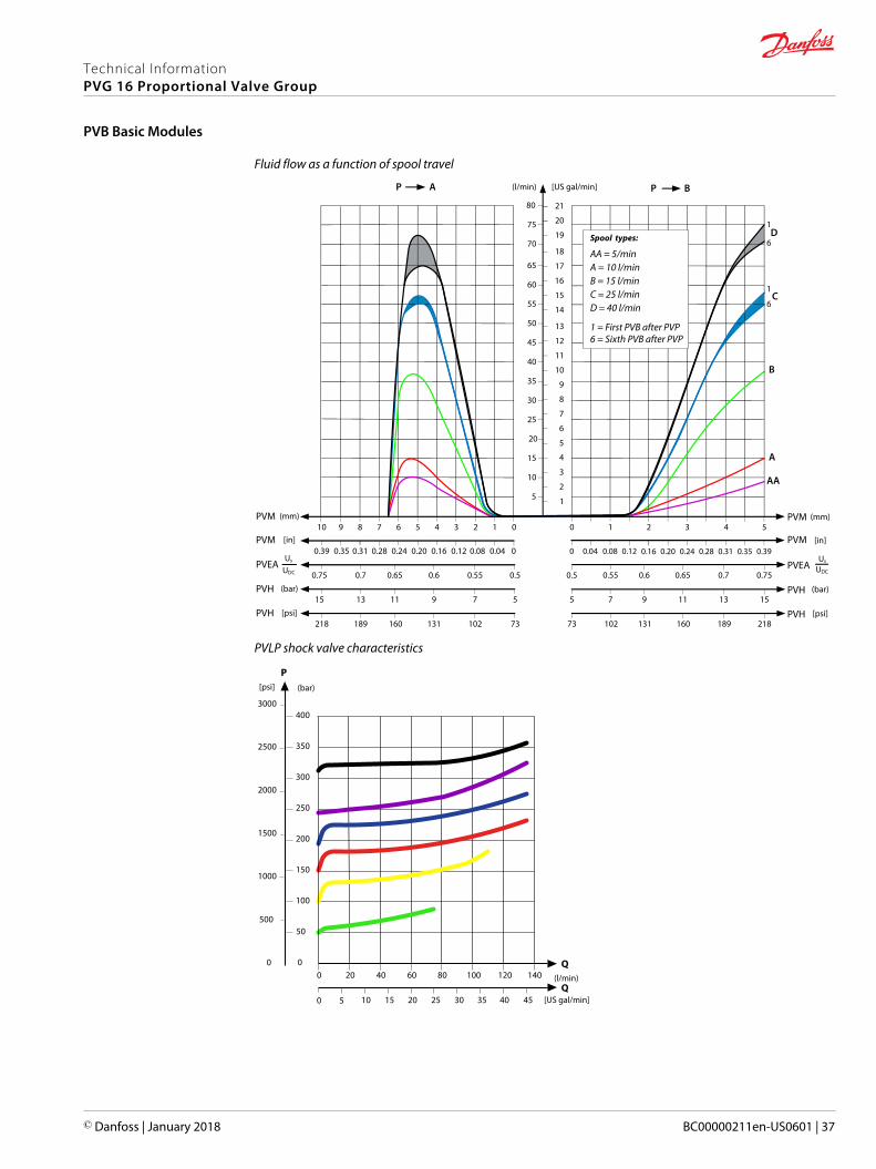
Fluid flow as a function of spool travel
AP
5
10
15
20
25
30
35
40
45
50
55
60
65
(l/min) [US gal/min]
PVM (mm)0
0
1234567PVM [in]
0.28 0.24 0.20 0.16 0.12 0.08 0.04
PVEA0.50.550.60.650.7
8
0.31
0.75
910
70
75
80
0.39 0.35
1
2
3
4
5
6
7
8
9
10
11
12
13
14
15
16
17
18
19
20
21
BP
PVM543
PVM0.20 0.24 0.28 0.31 0.35 0.39
PVEA0.70.650.60.55
2
0.16
0.5
10
0 0.04 0.08 0.12
0.75
PVHPVH (bar)
AA
B
C
D
A
579111315 1311975 15
PVH73218
PVH73 218
[psi]189 160 131 102 102 131 160 189
Us
UDC
Us
UDC
1
1
6
6
Spool types:
A = 10 l/minB = 15 l/min
AA = 5/min
C = 25 l/minD = 40 l/min
1 = First PVB after PVP6 = Sixth PVB after PVP
(mm)
[in]
(bar)
[psi]
PVLP shock valve characteristics
(l/min)
[US gal/min]
P
Q
Q
(bar)[psi]
20 40 60 80 100 120 140
5 10 15 20 25 30 35 40 45
400
350
300
250
200
150
100
50
0
2500
2000
1500
1000
500
0
3000
0
0
Technical InformationPVG 16 Proportional Valve Group
PVB Basic Modules
© Danfoss | January 2018 BC00000211en-US0601 | 37
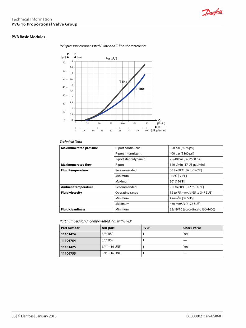
PVB pressure compensated P-line and T-line characteristics
Q
Q
P[psi]
(l/min)
[US gal/min]
5
4,5
4
3,5
3
2,5
2
1,5
1
0,5
0
50
50
40
30
20
10
0
70
7525
5 10 15 20 25 30 35 40
100 125 150
60
0
0
Port A/B
T-line
P-line
P(bar)
Technical Data
Maximum rated pressure P-port continuous 350 bar [5076 psi]
P-port intermittent 400 bar [5800 psi]
T-port static/dynamic 25/40 bar [363/580 psi]
Maximum rated flow P-port 140 l/min [37 US gal/min]
Fluid temperature Recommended 30 to 60°C [86 to 140°F]
Minimum -30°C [-22°F]
Maximum 90° [194°F]
Ambient temperature Recommended -30 to 60°C [-22 to 140°F]
Fluid viscosity Operating range 12 to 75 mm2/s [65 to 347 SUS]
Minimum 4 mm2/s [39 SUS]
Maximum 460 mm2/s [2128 SUS]
Fluid cleanliness Minimum 23/19/16 (according to ISO 4406)
Part numbers for Uncompensated PVB with PVLP
Part number A/B-port PVLP Check valve
11101424 3/8” BSP 1 Yes
11106754 3/8” BSP 1 —
11101425 3/4” – 16 UNF 1 Yes
11106755 3/4” – 16 UNF 1 —
Technical InformationPVG 16 Proportional Valve Group
PVB Basic Modules
38 | © Danfoss | January 2018 BC00000211en-US0601
PVLP, Shock/Anti-Cavitation and PVLA, Suction Valves
The PVLP Shock/Anti-Cavitation valve is an accessory available for PVB basic and PVP inlet modules. ThePVLA valve is an accessory available for PVB basic modules only.
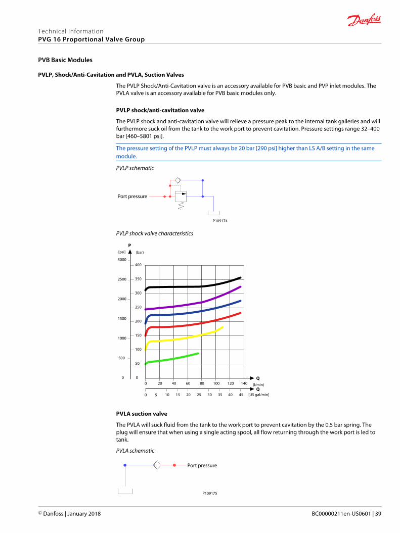
PVLP shock/anti-cavitation valve
The PVLP shock and anti-cavitation valve will relieve a pressure peak to the internal tank galleries and willfurthermore suck oil from the tank to the work port to prevent cavitation. Pressure settings range 32–400bar [460–5801 psi].
The pressure setting of the PVLP must always be 20 bar [290 psi] higher than LS A/B setting in the samemodule.
PVLP schematic
P109174
Port pressure
PVLP shock valve characteristics
(l/min)
[US gal/min]
P
Q
Q
(bar)[psi]
20 40 60 80 100 120 140
5 10 15 20 25 30 35 40 45
400
350
300
250
200
150
100
50
0
2500
2000
1500
1000
500
0
3000
0
0
PVLA suction valve
The PVLA will suck fluid from the tank to the work port to prevent cavitation by the 0.5 bar spring. Theplug will ensure that when using a single acting spool, all flow returning through the work port is led totank.
PVLA schematic
P109175
Port pressure
Technical InformationPVG 16 Proportional Valve Group
PVB Basic Modules
© Danfoss | January 2018 BC00000211en-US0601 | 39
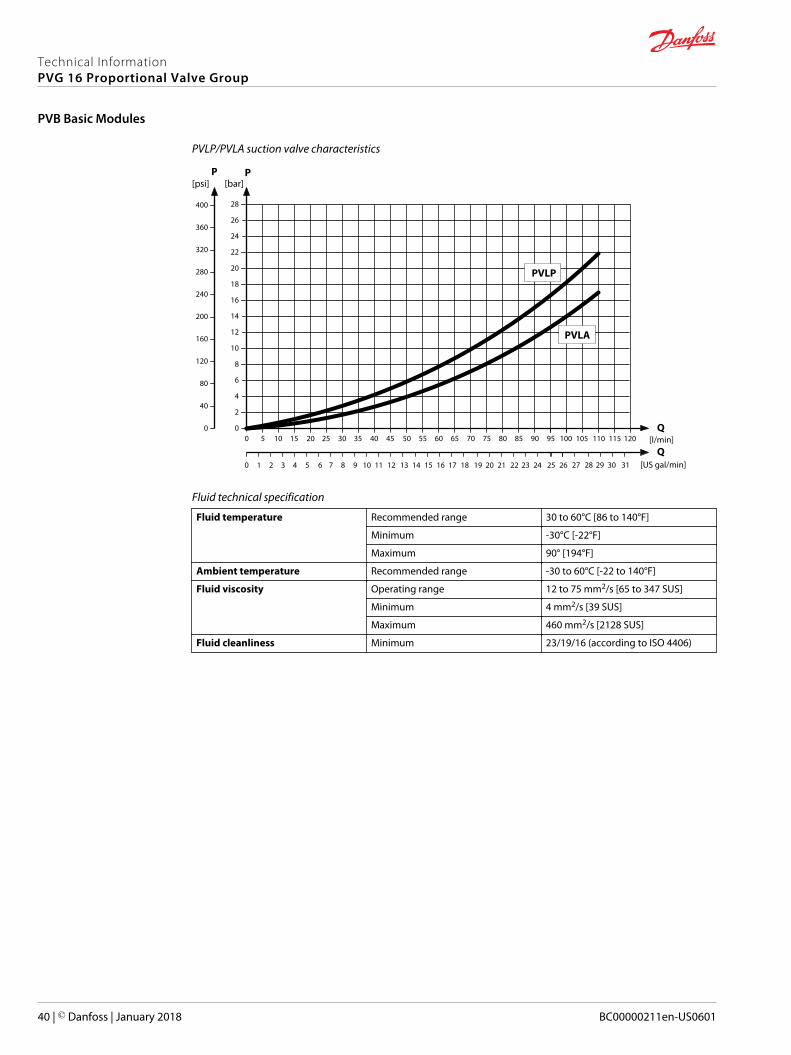
PVLP/PVLA suction valve characteristics
5 10 15 20 25 30 35 40 45 50 55 60 65 [l/min]
[US gal/min]
70 75 80
1 2 3 4 5 6 7 8 9 10 11 12 13 14 15 16 17 18 19 20 21
20
18
16
14
12
10
8
6
4
2
085 90 95 100
22 23 24 25 26
Q
28
26
24
22
PP
200
160
120
80
40
0
280
240
320
400
360
0
[psi] [bar]
0
Q105 110 115 120
27 28 29 30 31
PVLP
PVLA
Fluid technical specification
Fluid temperature Recommended range 30 to 60°C [86 to 140°F]
Minimum -30°C [-22°F]
Maximum 90° [194°F]
Ambient temperature Recommended range -30 to 60°C [-22 to 140°F]
Fluid viscosity Operating range 12 to 75 mm2/s [65 to 347 SUS]
Minimum 4 mm2/s [39 SUS]
Maximum 460 mm2/s [2128 SUS]
Fluid cleanliness Minimum 23/19/16 (according to ISO 4406)
Technical InformationPVG 16 Proportional Valve Group
PVB Basic Modules
40 | © Danfoss | January 2018 BC00000211en-US0601
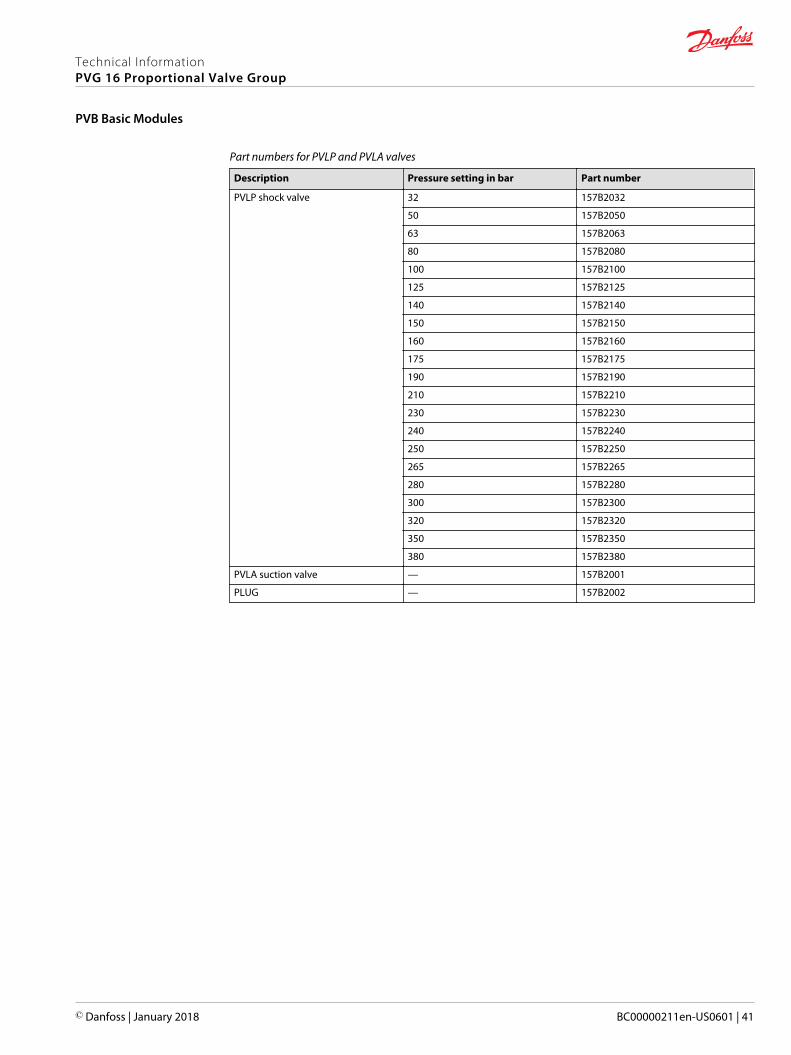
Part numbers for PVLP and PVLA valves
Description Pressure setting in bar Part number
PVLP shock valve 32 157B2032
50 157B2050
63 157B2063
80 157B2080
100 157B2100
125 157B2125
140 157B2140
150 157B2150
160 157B2160
175 157B2175
190 157B2190
210 157B2210
230 157B2230
240 157B2240
250 157B2250
265 157B2265
280 157B2280
300 157B2300
320 157B2320
350 157B2350
380 157B2380
PVLA suction valve — 157B2001
PLUG — 157B2002
Technical InformationPVG 16 Proportional Valve Group
PVB Basic Modules
© Danfoss | January 2018 BC00000211en-US0601 | 41
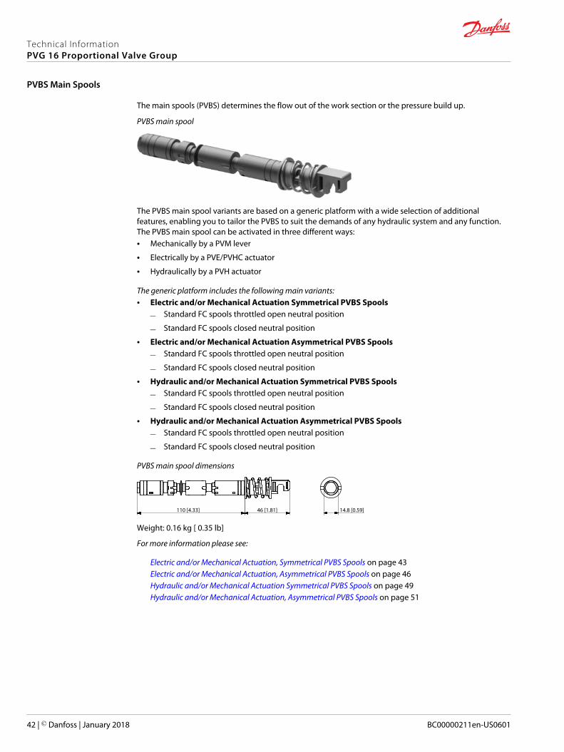
The main spools (PVBS) determines the flow out of the work section or the pressure build up.
PVBS main spool
The PVBS main spool variants are based on a generic platform with a wide selection of additionalfeatures, enabling you to tailor the PVBS to suit the demands of any hydraulic system and any function.The PVBS main spool can be activated in three different ways:• Mechanically by a PVM lever
• Electrically by a PVE/PVHC actuator
• Hydraulically by a PVH actuator
The generic platform includes the following main variants:• Electric and/or Mechanical Actuation Symmetrical PVBS Spools
‒ Standard FC spools throttled open neutral position
‒ Standard FC spools closed neutral position
• Electric and/or Mechanical Actuation Asymmetrical PVBS Spools
‒ Standard FC spools throttled open neutral position
‒ Standard FC spools closed neutral position
• Hydraulic and/or Mechanical Actuation Symmetrical PVBS Spools
‒ Standard FC spools throttled open neutral position
‒ Standard FC spools closed neutral position
• Hydraulic and/or Mechanical Actuation Asymmetrical PVBS Spools
‒ Standard FC spools throttled open neutral position
‒ Standard FC spools closed neutral position
PVBS main spool dimensions
110 [4.33] 14.8 [0.59]46 [1.81]
Weight: 0.16 kg [ 0.35 lb]
For more information please see:
Electric and/or Mechanical Actuation, Symmetrical PVBS Spools on page 43Electric and/or Mechanical Actuation, Asymmetrical PVBS Spools on page 46Hydraulic and/or Mechanical Actuation Symmetrical PVBS Spools on page 49Hydraulic and/or Mechanical Actuation, Asymmetrical PVBS Spools on page 51
Technical InformationPVG 16 Proportional Valve Group
PVBS Main Spools
42 | © Danfoss | January 2018 BC00000211en-US0601
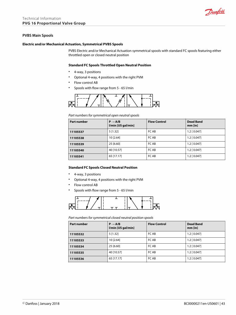
Electric and/or Mechanical Actuation, Symmetrical PVBS Spools
PVBS Electric and/or Mechanical Actuation symmetrical spools with standard FC spools featuring eitherthrottled open or closed neutral position
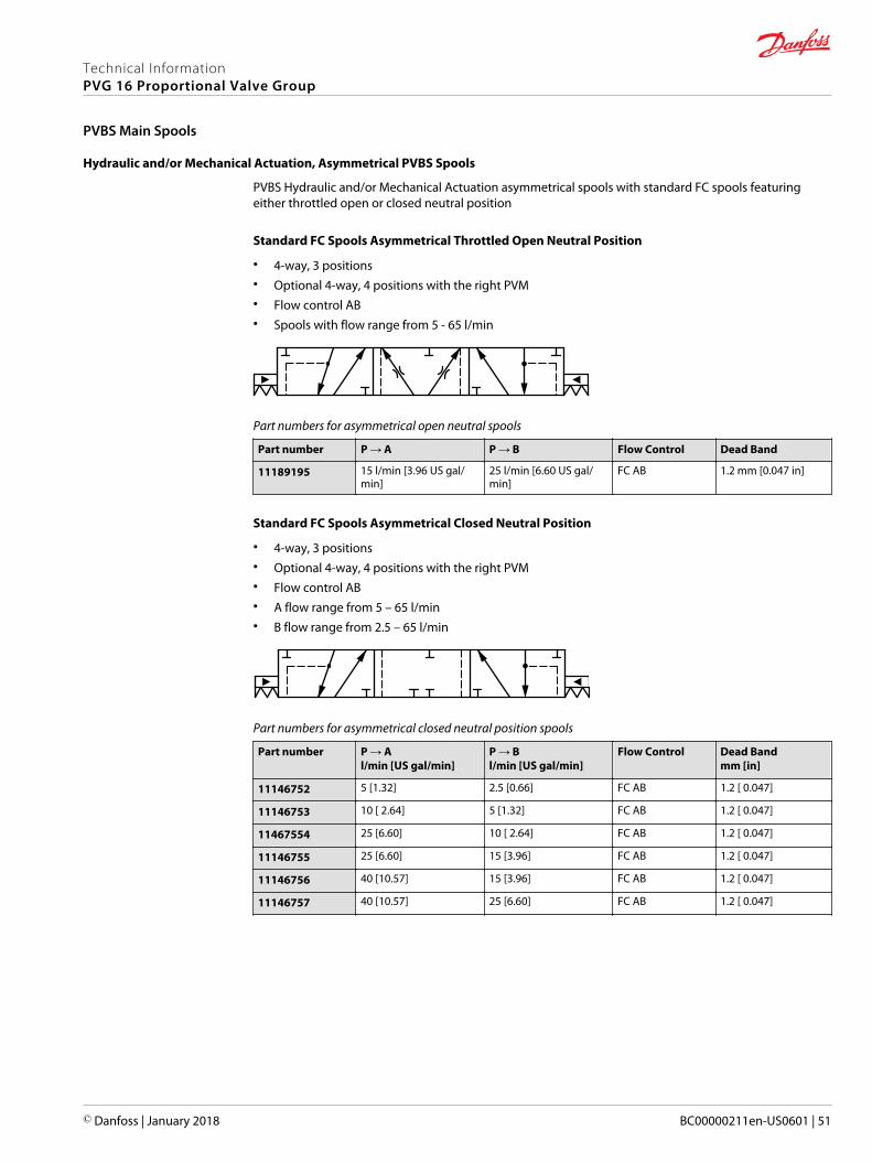
Standard FC Spools Throttled Open Neutral Position
• 4-way, 3 positions• Optional 4-way, 4 positions with the right PVM• Flow control AB• Spools with flow range from 5 - 65 l/min
Part numbers for symmetrical open neutral spools
Part number P → A/Bl/min [US gal/min]
Flow Control Dead Bandmm [in]
11105537 5 [1.32] FC AB 1.2 [ 0.047]
11105538 10 [2.64] FC AB 1.2 [ 0.047]
11105539 25 [6.60] FC AB 1.2 [ 0.047]
11105540 40 [10.57] FC AB 1.2 [ 0.047]
11105541 65 [17.17] FC AB 1.2 [ 0.047]
Standard FC Spools Closed Neutral Position
• 4-way, 3 positions• Optional 4-way, 4 positions with the right PVM• Flow control AB• Spools with flow range from 5 - 65 l/min
Part numbers for symmetrical closed neutral position spools
Part number P → A/Bl/min [US gal/min]
Flow Control Dead Bandmm [in]
11105532 5 [1.32] FC AB 1.2 [ 0.047]
11105533 10 [2.64] FC AB 1.2 [ 0.047]
11105534 25 [6.60] FC AB 1.2 [ 0.047]
11105535 40 [10.57] FC AB 1.2 [ 0.047]
11105536 65 [17.17] FC AB 1.2 [ 0.047]
Technical InformationPVG 16 Proportional Valve Group
PVBS Main Spools
© Danfoss | January 2018 BC00000211en-US0601 | 43
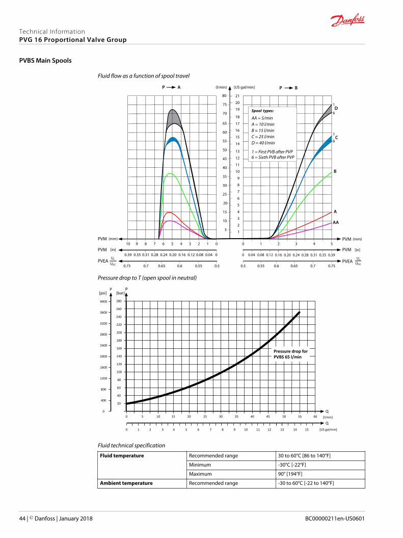
Fluid flow as a function of spool travel
AP
5
10
15
20
25
30
35
40
45
50
55
60
65
(l/min) [US gal/min]
PVM (mm)0
0
1234567PVM [in]
0.28 0.24 0.20 0.16 0.12 0.08 0.04
PVEA0.50.550.60.650.7
8
0.31
0.75
910
70
75
80
0.39 0.35
1
2
3
4
5
6
7
8
9
10
11
12
13
14
15
16
17
18
19
20
21
BP
PVM543
PVM0.20 0.24 0.28 0.31 0.35 0.39
PVEA0.70.650.60.55
2
0.16
0.5
10
0 0.04 0.08 0.12
0.75
AA
B
C
D
A
Us
UDC
Us
UDC
1
1
6
6
Spool types:
A = 10 l/minB = 15 l/min
AA = 5/min
C = 25 l/minD = 40 l/min
1 = First PVB after PVP6 = Sixth PVB after PVP
(mm)
[in]
Pressure drop to T (open spool in neutral)
5 10 15 20 25 30 [l/min]
[US gal/min]
35 40
1 2 3 4 5 6 7 8 9 10
200
180
160
140
120
100
80
60
40
20
45 50
11 12 13
Q
280
260
240
220
PP
2000
1600
1200
800
400
0
2800
2400
3200
4000
3600
0
[psi]
0
Q55 60
14 15
(bar)
Pressure drop for PVBS 65 l/min
Fluid technical specification
Fluid temperature Recommended range 30 to 60°C [86 to 140°F]
Minimum -30°C [-22°F]
Maximum 90° [194°F]
Ambient temperature Recommended range -30 to 60°C [-22 to 140°F]
Technical InformationPVG 16 Proportional Valve Group
PVBS Main Spools
44 | © Danfoss | January 2018 BC00000211en-US0601
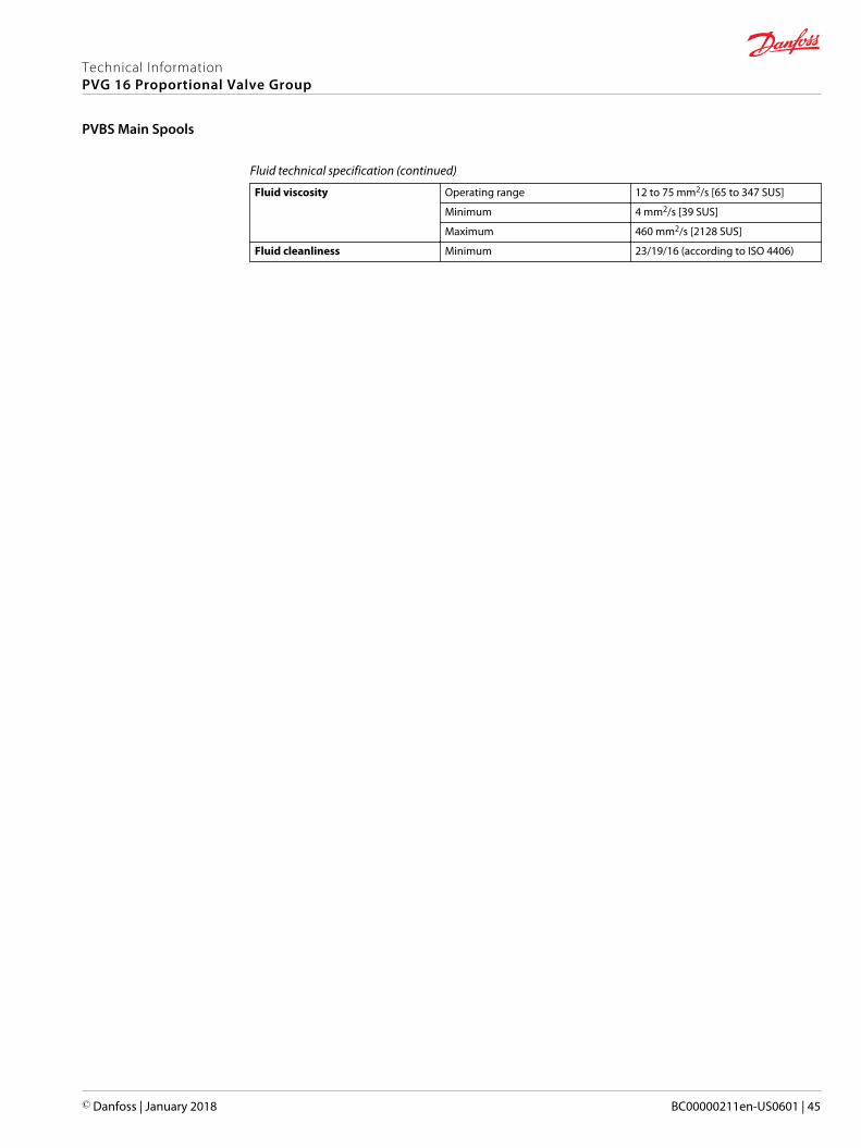
Fluid technical specification (continued)
Fluid viscosity Operating range 12 to 75 mm2/s [65 to 347 SUS]
Minimum 4 mm2/s [39 SUS]
Maximum 460 mm2/s [2128 SUS]
Fluid cleanliness Minimum 23/19/16 (according to ISO 4406)
Technical InformationPVG 16 Proportional Valve Group
PVBS Main Spools
© Danfoss | January 2018 BC00000211en-US0601 | 45
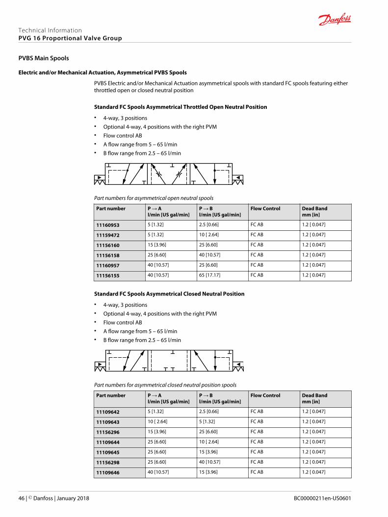
Electric and/or Mechanical Actuation, Asymmetrical PVBS Spools
PVBS Electric and/or Mechanical Actuation asymmetrical spools with standard FC spools featuring eitherthrottled open or closed neutral position
Standard FC Spools Asymmetrical Throttled Open Neutral Position
• 4-way, 3 positions• Optional 4-way, 4 positions with the right PVM• Flow control AB• A flow range from 5 – 65 l/min• B flow range from 2.5 – 65 l/min
Part numbers for asymmetrical open neutral spools
Part number P → Al/min [US gal/min]
P → Bl/min [US gal/min]
Flow Control Dead Bandmm [in]
11160953 5 [1.32] 2.5 [0.66] FC AB 1.2 [ 0.047]
11159472 5 [1.32] 10 [ 2.64] FC AB 1.2 [ 0.047]
11156160 15 [3.96] 25 [6.60] FC AB 1.2 [ 0.047]
11156158 25 [6.60] 40 [10.57] FC AB 1.2 [ 0.047]
11160957 40 [10.57] 25 [6.60] FC AB 1.2 [ 0.047]
11156155 40 [10.57] 65 [17.17] FC AB 1.2 [ 0.047]
Standard FC Spools Asymmetrical Closed Neutral Position
• 4-way, 3 positions• Optional 4-way, 4 positions with the right PVM• Flow control AB• A flow range from 5 – 65 l/min• B flow range from 2.5 – 65 l/min
Part numbers for asymmetrical closed neutral position spools
Part number P → Al/min [US gal/min]
P → Bl/min [US gal/min]
Flow Control Dead Bandmm [in]
11109642 5 [1.32] 2.5 [0.66] FC AB 1.2 [ 0.047]
11109643 10 [ 2.64] 5 [1.32] FC AB 1.2 [ 0.047]
11156296 15 [3.96] 25 [6.60] FC AB 1.2 [ 0.047]
11109644 25 [6.60] 10 [ 2.64] FC AB 1.2 [ 0.047]
11109645 25 [6.60] 15 [3.96] FC AB 1.2 [ 0.047]
11156298 25 [6.60] 40 [10.57] FC AB 1.2 [ 0.047]
11109646 40 [10.57] 15 [3.96] FC AB 1.2 [ 0.047]
Technical InformationPVG 16 Proportional Valve Group
PVBS Main Spools
46 | © Danfoss | January 2018 BC00000211en-US0601
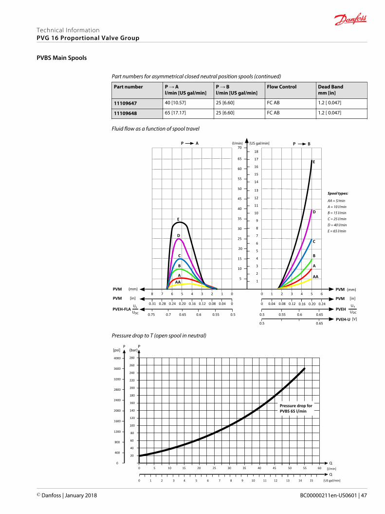
Part numbers for asymmetrical closed neutral position spools (continued)
Part number P → Al/min [US gal/min]
P → Bl/min [US gal/min]
Flow Control Dead Bandmm [in]
11109647 40 [10.57] 25 [6.60] FC AB 1.2 [ 0.047]
11109648 65 [17.17] 25 [6.60] FC AB 1.2 [ 0.047]
Fluid flow as a function of spool travel
AP (l/min) [US gal/min] BP
5
10
15
20
25
30
35
40
45
50
55
60
65
(mm) (mm)PVM01234567
[in]PVM00.040.080.120.160.200.240.28
PVEH-FLAUs
UDC 0.50.550.60.650.7
8
0.31
0.75
70
1
2
3
4
5
6
7
8
9
10
11
12
13
14
15
16
17
18
PVM65
[in]PVM0.240.20
PVEHUs
UDC0.650.60.55
4
0.16
0.5
3210
0.120.080.040
PVEH-U0.5
[V]
A
B
C
D
E
AA
0.65
A
B
C
D
E
AA
Spool types:
AA = 5/min
A = 10 l/min
B = 15 l/min
C = 25 l/min
D = 40 l/min
E = 65 l/min
Pressure drop to T (open spool in neutral)
5 10 15 20 25 30 [l/min]
[US gal/min]
35 40
1 2 3 4 5 6 7 8 9 10
200
180
160
140
120
100
80
60
40
20
45 50
11 12 13
Q
280
260
240
220
PP
2000
1600
1200
800
400
0
2800
2400
3200
4000
3600
0
[psi]
0
Q55 60
14 15
(bar)
Pressure drop for PVBS 65 l/min
Technical InformationPVG 16 Proportional Valve Group
PVBS Main Spools
© Danfoss | January 2018 BC00000211en-US0601 | 47
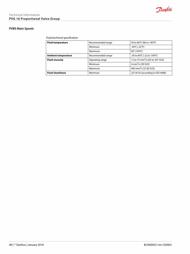
Fluid technical specification
Fluid temperature Recommended range 30 to 60°C [86 to 140°F]
Minimum -30°C [-22°F]
Maximum 90° [194°F]
Ambient temperature Recommended range -30 to 60°C [-22 to 140°F]
Fluid viscosity Operating range 12 to 75 mm2/s [65 to 347 SUS]
Minimum 4 mm2/s [39 SUS]
Maximum 460 mm2/s [2128 SUS]
Fluid cleanliness Minimum 23/19/16 (according to ISO 4406)
Technical InformationPVG 16 Proportional Valve Group
PVBS Main Spools
48 | © Danfoss | January 2018 BC00000211en-US0601

Hydraulic and/or Mechanical Actuation Symmetrical PVBS Spools
PVBS Hydraulic and/or Mechanical Actuation symmetrical spools with standard FC spools featuring eitherthrottled open or closed neutral position
Standard FC Spools Throttled Open Neutral Position
• 4-way, 3 positions• Optional 4-way, 4 positions with the right PVM• Flow control AB• Spools with flow range from 5 - 65 l/min
Part numbers for symmetrical open neutral spools
Part number P → A/Bl/min [US gal/min]
Flow Control Dead Bandmm [in]
11109637 5 [1.32] FC AB 1.2 [ 0.047]
11109638 10 [2.64] FC AB 1.2 [ 0.047]
11109639 25 [6.60] FC AB 1.2 [ 0.047]
11109640 40 [10.57] FC AB 1.2 [ 0.047]
11109641 65 [17.17] FC AB 1.2 [ 0.047]
Standard FC Spools Closed Neutral Position
• 4-way, 3 positions• Optional 4-way, 4 positions with the right PVM• Flow control AB• Spools with flow range from 5 - 65 l/min
Part numbers for symmetrical closed neutral position spools
Part number P → A/Bl/min [US gal/min]
Flow Control Dead Bandmm [in]
11109632 5 [1.32] FC AB 1.2 [ 0.047]
11109633 10 [2.64] FC AB 1.2 [ 0.047]
11109634 25 [6.60] FC AB 1.2 [ 0.047]
11109635 40 [10.57] FC AB 1.2 [ 0.047]
11109636 65 [17.17] FC AB 1.2 [ 0.047]
Technical InformationPVG 16 Proportional Valve Group
PVBS Main Spools
© Danfoss | January 2018 BC00000211en-US0601 | 49
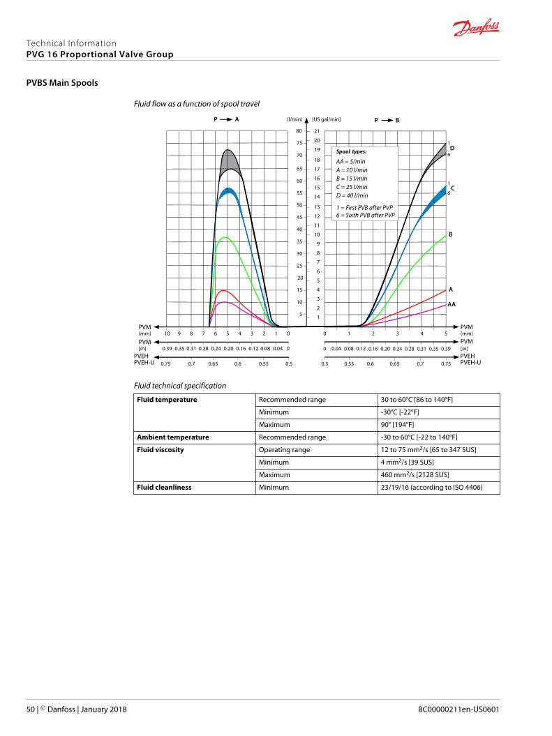
Fluid flow as a function of spool travel
AP
5
10
15
20
25
30
35
40
45
50
55
60
65
(l/min) [US gal/min]
PVM(mm) 0
0
1234567
PVM[in] 0.28 0.24 0.20 0.16 0.12 0.08 0.04
PVEH0.50.550.60.650.7
8
0.31
0.75
910
70
75
80
0.39 0.35
1
2
3
4
5
6
7
8
9
10
11
12
13
14
15
16
17
18
19
20
21
BP
PVM543
PVM0.20 0.24 0.28 0.31 0.35 0.39
PVEHPVEH-UPVEH-U 0.70.650.60.55
2
0.16
0.5
10
0 0.04 0.08 0.12
0.75
AA
B
C
D
A
1
1
6
6
Spool types:
A = 10 l/minB = 15 l/min
AA = 5/min
C = 25 l/minD = 40 l/min
1 = First PVB after PVP6 = Sixth PVB after PVP
(mm)
[in]
Fluid technical specification
Fluid temperature Recommended range 30 to 60°C [86 to 140°F]
Minimum -30°C [-22°F]
Maximum 90° [194°F]
Ambient temperature Recommended range -30 to 60°C [-22 to 140°F]
Fluid viscosity Operating range 12 to 75 mm2/s [65 to 347 SUS]
Minimum 4 mm2/s [39 SUS]
Maximum 460 mm2/s [2128 SUS]
Fluid cleanliness Minimum 23/19/16 (according to ISO 4406)
Technical InformationPVG 16 Proportional Valve Group
PVBS Main Spools
50 | © Danfoss | January 2018 BC00000211en-US0601
Hydraulic and/or Mechanical Actuation, Asymmetrical PVBS Spools
PVBS Hydraulic and/or Mechanical Actuation asymmetrical spools with standard FC spools featuringeither throttled open or closed neutral position
Standard FC Spools Asymmetrical Throttled Open Neutral Position
• 4-way, 3 positions• Optional 4-way, 4 positions with the right PVM• Flow control AB• Spools with flow range from 5 - 65 l/min
Part numbers for asymmetrical open neutral spools
Part number P → A P → B Flow Control Dead Band
11189195 15 l/min [3.96 US gal/min]
25 l/min [6.60 US gal/min]
FC AB 1.2 mm [0.047 in]
Standard FC Spools Asymmetrical Closed Neutral Position
• 4-way, 3 positions• Optional 4-way, 4 positions with the right PVM• Flow control AB• A flow range from 5 – 65 l/min• B flow range from 2.5 – 65 l/min
Part numbers for asymmetrical closed neutral position spools
Part number P → Al/min [US gal/min]
P → Bl/min [US gal/min]
Flow Control Dead Bandmm [in]
11146752 5 [1.32] 2.5 [0.66] FC AB 1.2 [ 0.047]
11146753 10 [ 2.64] 5 [1.32] FC AB 1.2 [ 0.047]
11467554 25 [6.60] 10 [ 2.64] FC AB 1.2 [ 0.047]
11146755 25 [6.60] 15 [3.96] FC AB 1.2 [ 0.047]
11146756 40 [10.57] 15 [3.96] FC AB 1.2 [ 0.047]
11146757 40 [10.57] 25 [6.60] FC AB 1.2 [ 0.047]
Technical InformationPVG 16 Proportional Valve Group
PVBS Main Spools
© Danfoss | January 2018 BC00000211en-US0601 | 51
Fluid flow as a function of spool travel
AP (l/min) [US gal/min] BP
5
10
15
20
25
30
35
40
45
50
55
60
65
(mm) (mm)PVM01234567
[in]PVM00.040.080.120.160.200.240.28
PVEH-FLAUs
UDC 0.50.550.60.650.7
8
0.31
0.75
70
1
2
3
4
5
6
7
8
9
10
11
12
13
14
15
16
17
18
PVM65
[in]PVM0.240.20
PVEHUs
UDC0.650.60.55
4
0.16
0.5
3210
0.120.080.040
PVEH-U0.5
[V]
A
B
C
D
E
AA
0.65
A
B
C
D
E
AA
Spool types:
AA = 5/min
A = 10 l/min
B = 15 l/min
C = 25 l/min
D = 40 l/min
E = 65 l/min
Pressure drop to T (open spool in neutral)
5 10 15 20 25 30 [l/min]
[US gal/min]
35 40
1 2 3 4 5 6 7 8 9 10
200
180
160
140
120
100
80
60
40
20
45 50
11 12 13
Q
280
260
240
220
PP
2000
1600
1200
800
400
0
2800
2400
3200
4000
3600
0
[psi]
0
Q55 60
14 15
(bar)
Pressure drop for PVBS 65 l/min
Fluid technical specification
Fluid temperature Recommended range 30 to 60°C [86 to 140°F]
Minimum -30°C [-22°F]
Maximum 90° [194°F]
Ambient temperature Recommended range -30 to 60°C [-22 to 140°F]
Technical InformationPVG 16 Proportional Valve Group
PVBS Main Spools
52 | © Danfoss | January 2018 BC00000211en-US0601

Fluid technical specification (continued)
Fluid viscosity Operating range 12 to 75 mm2/s [65 to 347 SUS]
Minimum 4 mm2/s [39 SUS]
Maximum 460 mm2/s [2128 SUS]
Fluid cleanliness Minimum 23/19/16 (according to ISO 4406)
Technical InformationPVG 16 Proportional Valve Group
PVBS Main Spools
© Danfoss | January 2018 BC00000211en-US0601 | 53
PVG 16 Manual, Hydraulic, Electro-hydraulic and Electrical Actuation overview.
PVG 16 Actuation can be done by:• PVM Manual Actuation, see more PVM Manual Actuation on page 54
‒ PVMD cover, see more PVMD Cover on page 56
• PVH Hydraulic Actuation, see more PVH Hydraulic Actuation on page 57
• PVHC Electro-hydraulic Actuation, see more PVHC Electro-Hydraulic Actuation on page 59
• PVE Electrical Actuation, see more PVE Electrical Actuation on page 61
‒ PVEO, see more PVEO – ON/OFF Voltage Control Actuator on page 63
‒ PVEA, see more PVEA – Proportional Spool Control Actuator on page 66
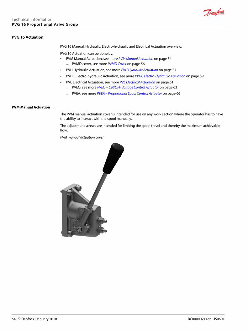
PVM Manual Actuation
The PVM manual actuation cover is intended for use on any work section where the operator has to havethe ability to interact with the spool manually.
The adjustment screws are intended for limiting the spool travel and thereby the maximum achievableflow.
PVM manual actuation cover
Technical InformationPVG 16 Proportional Valve Group
PVG 16 Actuation
54 | © Danfoss | January 2018 BC00000211en-US0601
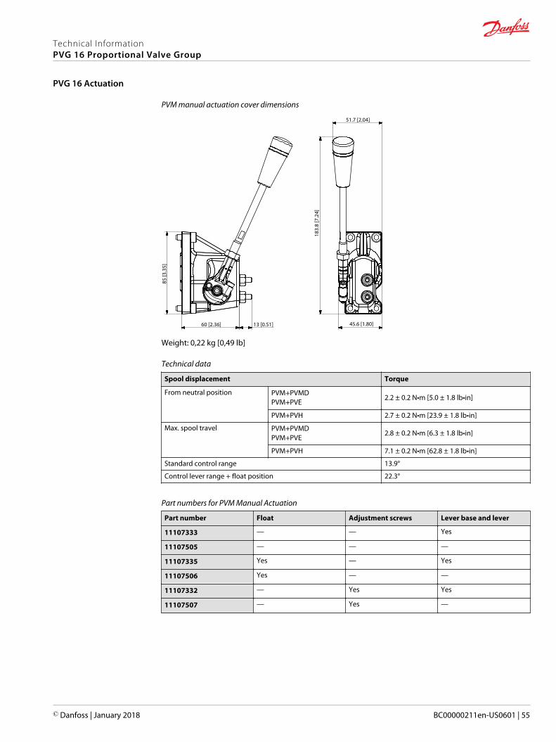
PVM manual actuation cover dimensions
183.
8 [7
.24]
85 [3
.35]
60 [2.36] 13 [0.51] 45.6 [1.80]
51.7 [2.04]
Weight: 0,22 kg [0,49 lb]
Technical data
Spool displacement Torque
From neutral position PVM+PVMDPVM+PVE
2.2 ± 0.2 N•m [5.0 ± 1.8 lb•in]
PVM+PVH 2.7 ± 0.2 N•m [23.9 ± 1.8 lb•in]
Max. spool travel PVM+PVMDPVM+PVE
2.8 ± 0.2 N•m [6.3 ± 1.8 lb•in]
PVM+PVH 7.1 ± 0.2 N•m [62.8 ± 1.8 lb•in]
Standard control range 13.9°
Control lever range + float position 22.3°
Part numbers for PVM Manual Actuation
Part number Float Adjustment screws Lever base and lever
11107333 — — Yes
11107505 — — —
11107335 Yes — Yes
11107506 Yes — —
11107332 — Yes Yes
11107507 — Yes —
Technical InformationPVG 16 Proportional Valve Group
PVG 16 Actuation
© Danfoss | January 2018 BC00000211en-US0601 | 55
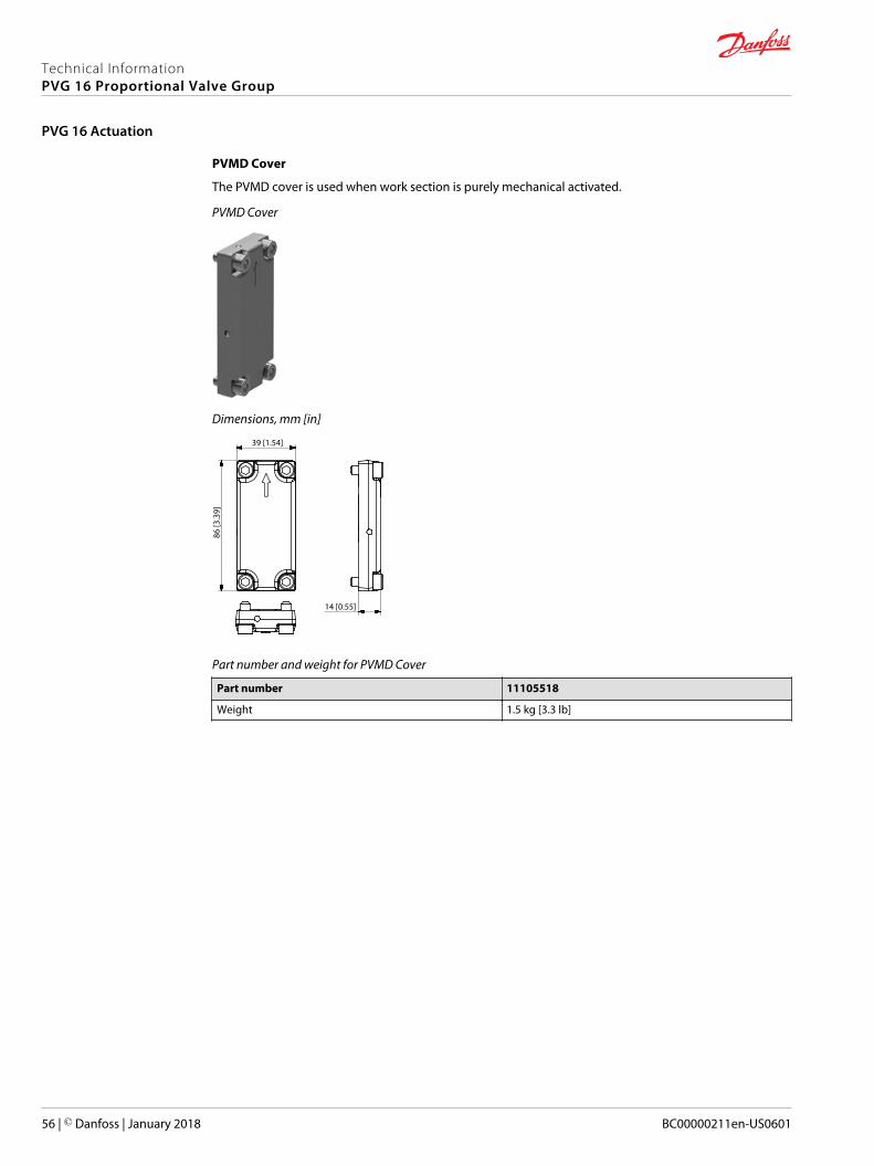
PVMD Cover
The PVMD cover is used when work section is purely mechanical activated.
PVMD Cover
Dimensions, mm [in]
86 [3
.39]
39 [1.54]
14 [0.55]
Part number and weight for PVMD Cover
Part number 11105518
Weight 1.5 kg [3.3 lb]
Technical InformationPVG 16 Proportional Valve Group
PVG 16 Actuation
56 | © Danfoss | January 2018 BC00000211en-US0601
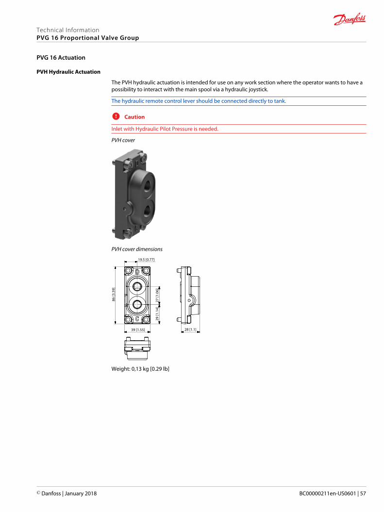
PVH Hydraulic Actuation
The PVH hydraulic actuation is intended for use on any work section where the operator wants to have apossibility to interact with the main spool via a hydraulic joystick.
The hydraulic remote control lever should be connected directly to tank.
C Caution
Inlet with Hydraulic Pilot Pressure is needed.
PVH cover
PVH cover dimensions
86 [3
.39]
27 [1
.06]
29 [1
.14]
39 [1.55] 28 [1.1]
19.5 [0.77]
Weight: 0,13 kg [0.29 lb]
Technical InformationPVG 16 Proportional Valve Group
PVG 16 Actuation
© Danfoss | January 2018 BC00000211en-US0601 | 57
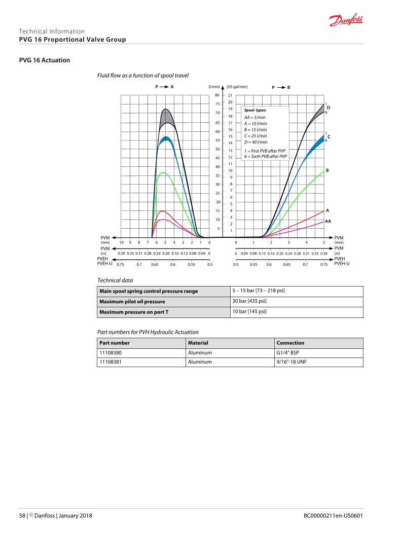
Fluid flow as a function of spool travel
AP
5
10
15
20
25
30
35
40
45
50
55
60
65
(l/min) [US gal/min]
PVM(mm) 0
0
1234567
PVM[in] 0.28 0.24 0.20 0.16 0.12 0.08 0.04
PVEH0.50.550.60.650.7
8
0.31
0.75
910
70
75
80
0.39 0.35
1
2
3
4
5
6
7
8
9
10
11
12
13
14
15
16
17
18
19
20
21
BP
PVM543
PVM0.20 0.24 0.28 0.31 0.35 0.39
PVEHPVEH-UPVEH-U 0.70.650.60.55
2
0.16
0.5
10
0 0.04 0.08 0.12
0.75
AA
B
C
D
A
1
1
6
6
Spool types:
A = 10 l/minB = 15 l/min
AA = 5/min
C = 25 l/minD = 40 l/min
1 = First PVB after PVP6 = Sixth PVB after PVP
(mm)
[in]
Technical data
Main spool spring control pressure range 5 – 15 bar [73 – 218 psi]
Maximum pilot oil pressure 30 bar [435 psi]
Maximum pressure on port T 10 bar [145 psi]
Part numbers for PVH Hydraulic Actuation
Part number Material Connection
11108380 Aluminum G1/4" BSP
11108381 Aluminum 9/16"-18 UNF
Technical InformationPVG 16 Proportional Valve Group
PVG 16 Actuation
58 | © Danfoss | January 2018 BC00000211en-US0601
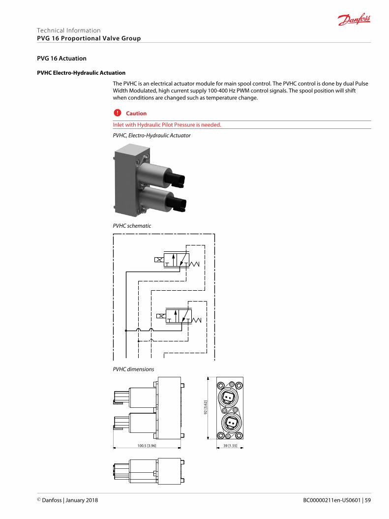
PVHC Electro-Hydraulic Actuation
The PVHC is an electrical actuator module for main spool control. The PVHC control is done by dual PulseWidth Modulated, high current supply 100-400 Hz PWM control signals. The spool position will shiftwhen conditions are changed such as temperature change.
C Caution
Inlet with Hydraulic Pilot Pressure is needed.
PVHC, Electro-Hydraulic Actuator
PVHC schematic
PVHC dimensions
92 [3
.62]
39 [1.55]100.5 [3.96]
Technical InformationPVG 16 Proportional Valve Group
PVG 16 Actuation
© Danfoss | January 2018 BC00000211en-US0601 | 59
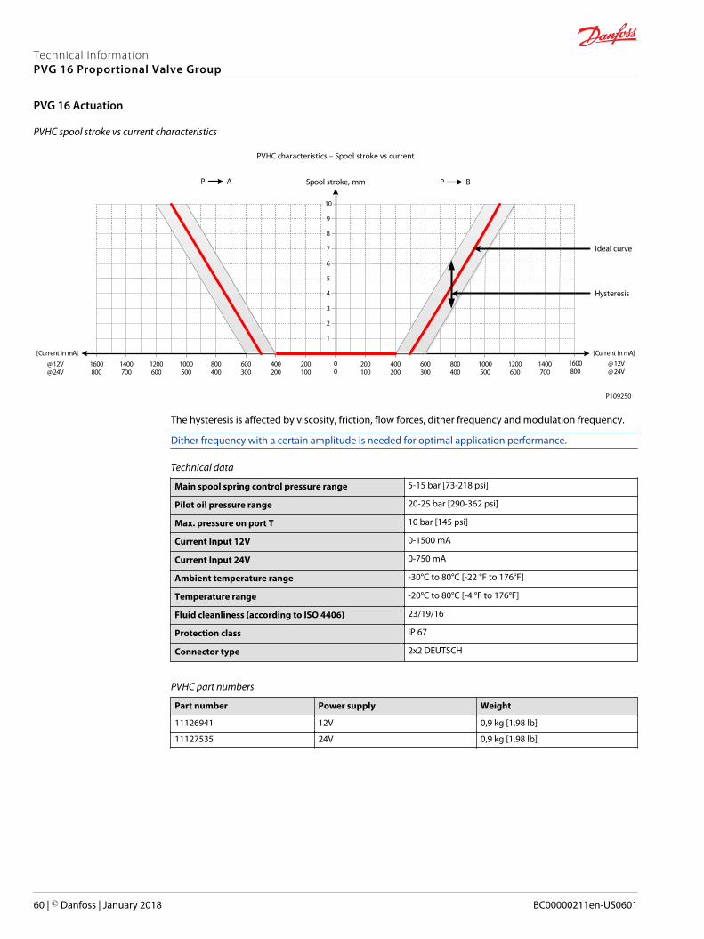
PVHC spool stroke vs current characteristics
AP
1
2
3
4
5
6
7
8
9
10
00
200100
400200
600300
800400
1000500
BP
800400
600300
400200
200100
1000500
[Current in mA][Current in mA]
@12V@24V
@12V@24V
1600800
1400700
1200600
1200600
1600800
1400700
Spool stroke, mm
PVHC characteristics – Spool stroke vs current
Ideal curve
Hysteresis
P109250
The hysteresis is affected by viscosity, friction, flow forces, dither frequency and modulation frequency.
Dither frequency with a certain amplitude is needed for optimal application performance.
Technical data
Main spool spring control pressure range 5-15 bar [73-218 psi]
Pilot oil pressure range 20-25 bar [290-362 psi]
Max. pressure on port T 10 bar [145 psi]
Current Input 12V 0-1500 mA
Current Input 24V 0-750 mA
Ambient temperature range -30°C to 80°C [-22 °F to 176°F]
Temperature range -20°C to 80°C [-4 °F to 176°F]
Fluid cleanliness (according to ISO 4406) 23/19/16
Protection class IP 67
Connector type 2x2 DEUTSCH
PVHC part numbers
Part number Power supply Weight
11126941 12V 0,9 kg [1,98 lb]
11127535 24V 0,9 kg [1,98 lb]
Technical InformationPVG 16 Proportional Valve Group
PVG 16 Actuation
60 | © Danfoss | January 2018 BC00000211en-US0601
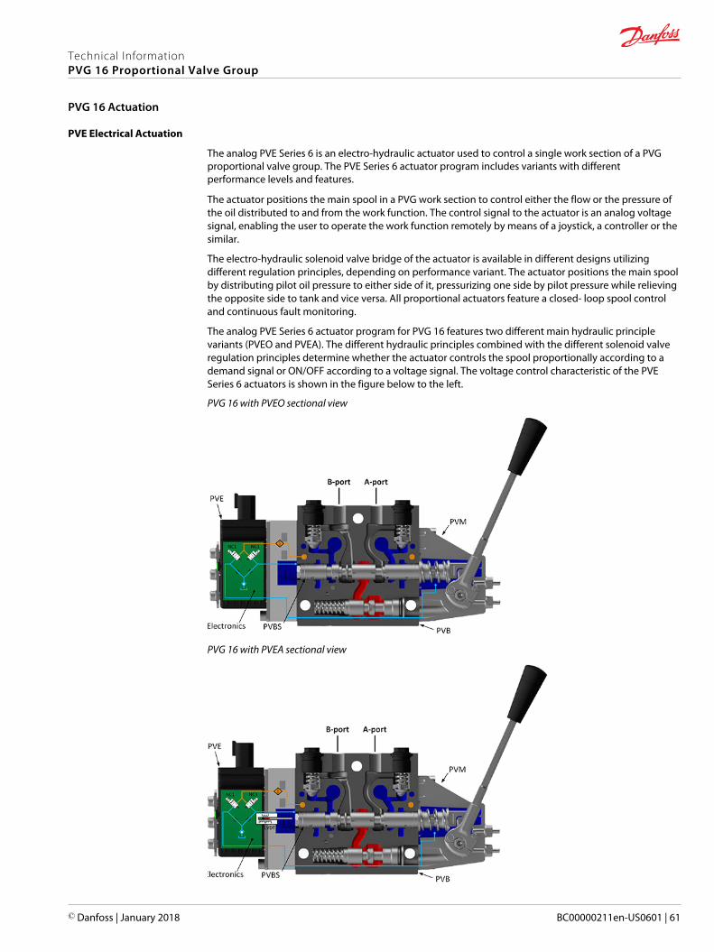
PVE Electrical Actuation
The analog PVE Series 6 is an electro-hydraulic actuator used to control a single work section of a PVGproportional valve group. The PVE Series 6 actuator program includes variants with differentperformance levels and features.
The actuator positions the main spool in a PVG work section to control either the flow or the pressure ofthe oil distributed to and from the work function. The control signal to the actuator is an analog voltagesignal, enabling the user to operate the work function remotely by means of a joystick, a controller or thesimilar.
The electro-hydraulic solenoid valve bridge of the actuator is available in different designs utilizingdifferent regulation principles, depending on performance variant. The actuator positions the main spoolby distributing pilot oil pressure to either side of it, pressurizing one side by pilot pressure while relievingthe opposite side to tank and vice versa. All proportional actuators feature a closed- loop spool controland continuous fault monitoring.
The analog PVE Series 6 actuator program for PVG 16 features two different main hydraulic principlevariants (PVEO and PVEA). The different hydraulic principles combined with the different solenoid valveregulation principles determine whether the actuator controls the spool proportionally according to ademand signal or ON/OFF according to a voltage signal. The voltage control characteristic of the PVESeries 6 actuators is shown in the figure below to the left.
PVG 16 with PVEO sectional view
PVG 16 with PVEA sectional view
Technical InformationPVG 16 Proportional Valve Group
PVG 16 Actuation
© Danfoss | January 2018 BC00000211en-US0601 | 61
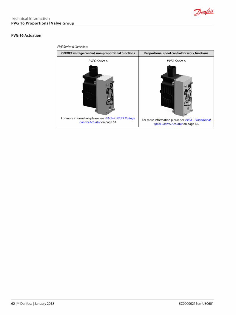
PVE Series 6 Overview
ON/OFF voltage control, non-proportional functions Proportional spool control for work functions
PVEO Series 6
For more information please see PVEO – ON/OFF VoltageControl Actuator on page 63.
PVEA Series 6
For more information please see PVEA – ProportionalSpool Control Actuator on page 66.
Technical InformationPVG 16 Proportional Valve Group
PVG 16 Actuation
62 | © Danfoss | January 2018 BC00000211en-US0601
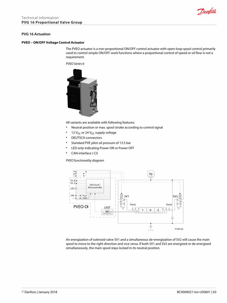
PVEO – ON/OFF Voltage Control Actuator
The PVEO actuator is a non-proportional ON/OFF control actuator with open-loop spool control primarilyused to control simple ON/OFF work functions where a proportional control of speed or oil flow is not arequirement.
PVEO Series 6
All variants are available with following features:• Neutral position or max. spool stroke according to control signal• 12 VDC or 24 VDC supply voltage• DEUTSCH connectors• Standard PVE pilot oil pressure of 13.5 bar• LED only indicating Power ON or Power OFF• CAN-interface (-CI)
PVEO functionality diagram
21 0
Pp
LVDT
LED Circuit /Microcontroller
PowerSupply
PVEO-DI
AB
DI_BDI_A
LED
Udc
Ramp Ramp
SV1 SV2
P109126
An energization of solenoid valve SV1 and a simultaneous de-energization of SV2 will cause the mainspool to move to the right direction and vice versa. If both SV1 and SV2 are energized or de-energizedsimultaneously, the main spool stays locked in its neutral position.
Technical InformationPVG 16 Proportional Valve Group
PVG 16 Actuation
© Danfoss | January 2018 BC00000211en-US0601 | 63

PVEO Series 6 schematic
PVEO Series 6 Dimensions
24 [0
.94]
92 [3
.62]
78.5 [3.09] 39 [1.54]
Weight: 0.7 kg [1.54 lb]
Technical InformationPVG 16 Proportional Valve Group
PVG 16 Actuation
64 | © Danfoss | January 2018 BC00000211en-US0601
PVEO Technical Data
PVEO/PVEO-CI actuator technical specification and part numbers.
Control specifications
Description Type 12 VDC ± 10% 24 VDC ± 10%
Supply Voltage (UDC) Rated/range 11 to 15 VDC 12 to 30 VDC
Max. ripple 5% 5%
Current Consumption Typical 320 mA 160 mA
Technical data
Pilot pressure Nominal 13.5 bar [196 psi]
Minimum 10.0 bar [145 psi]
Maximum 15.0 bar [218 psi]
Fluid consumption Neutral 0.04 l/min [0.01 US gal/min]
Locked position 0.04 l/min [0.01 US gal/min]
Actuating 0.6 l/min [0.16 US gal/min]
Fluid temperature Ambient Storage -50 to +90°C [-58 to +194°F]
Ambient Operating -40 to +90°C [-40 to +194°F]
Fluid viscosity Operating range 12 to 75 mm2/sec [65 to 347 SUS]
Minimum 4 mm2/sec [39 SUS]
Maximum 460 mm2/sec [2128 SUS]
Fluid cleanliness Minimum 18/16/13 (according to ISO 4406)
LED characteristic
Color LED characteristic Description
Green Power ON
Part numbers for PVEO and PVEO-CI
Part number Type Connector Protection Class Voltage Interface
11106793 PVEO 1x4 DEUTSCH IP 65 12 VDC —
11106794 PVEO 1x4 DEUTSCH IP 65 24 VDC —
11124002 PVEO-CI 1x4 DEUTSCH IP 67 — J1939/ISObus
11149443 PVEO-CI 1x4 DEUTSCH IP 67 — CANopen
Technical InformationPVG 16 Proportional Valve Group
PVG 16 Actuation
© Danfoss | January 2018 BC00000211en-US0601 | 65
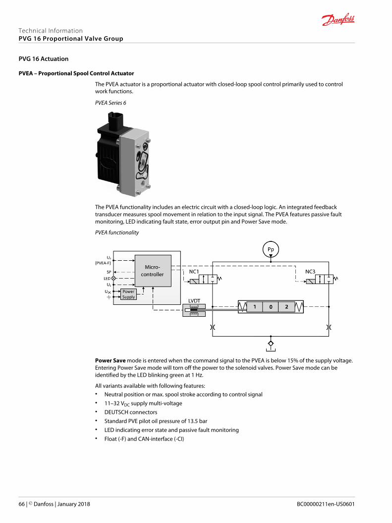
PVEA – Proportional Spool Control Actuator
The PVEA actuator is a proportional actuator with closed-loop spool control primarily used to controlwork functions.
PVEA Series 6
The PVEA functionality includes an electric circuit with a closed-loop logic. An integrated feedbacktransducer measures spool movement in relation to the input signal. The PVEA features passive faultmonitoring, LED indicating fault state, error output pin and Power Save mode.
PVEA functionality
Power Save mode is entered when the command signal to the PVEA is below 15% of the supply voltage.Entering Power Save mode will torn off the power to the solenoid valves. Power Save mode can beidentified by the LED blinking green at 1 Hz.
All variants available with following features:• Neutral position or max. spool stroke according to control signal• 11–32 VDC supply multi-voltage• DEUTSCH connectors• Standard PVE pilot oil pressure of 13.5 bar• LED indicating error state and passive fault monitoring• Float (-F) and CAN-interface (-CI)
Technical InformationPVG 16 Proportional Valve Group
PVG 16 Actuation
66 | © Danfoss | January 2018 BC00000211en-US0601

PVEA (-F) Series 6 schematic
PVEA (-F) Series 6 dimensions
24 [0
.94]
92 [3
.62]
78.5 [3.09] 39 [1.54]
Weight: 0.7 kg [1.54 lb]
PVEA Technical Data
PVEA/PVEA-CI/PVEA-F actuator technical specification and part numbers.
Control specification
Description Type Value
Supply voltage (UDC) Rated/range 11 to 32 VDC
Max. ripple 15 bar [218 psi]
Signal voltage (US) Neutral 0.5 UDC
Q: P -> A 0.25 UDC
Q: P -> B 0.75 UDC
Current consumption @ 12 VDC 320 mA
@ 24 VDC 170 mA
Input impedance Rated 12 kΩ
Input capacitance Rated 100 µF
Technical data
Pilot pressure Nominal 13.5 bar [196 psi]
Minimum 10.0 bar [145 psi]
Maximum 15.0 bar [218 psi]
Technical InformationPVG 16 Proportional Valve Group
PVG 16 Actuation
© Danfoss | January 2018 BC00000211en-US0601 | 67
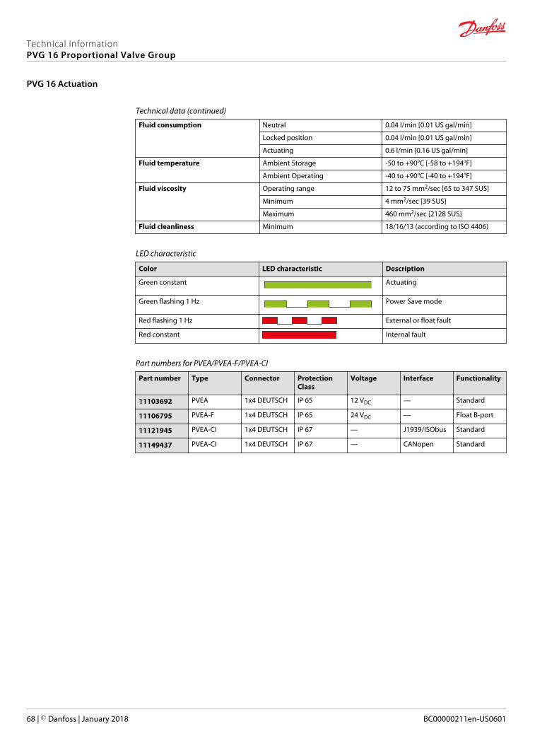
Technical data (continued)
Fluid consumption Neutral 0.04 l/min [0.01 US gal/min]
Locked position 0.04 l/min [0.01 US gal/min]
Actuating 0.6 l/min [0.16 US gal/min]
Fluid temperature Ambient Storage -50 to +90°C [-58 to +194°F]
Ambient Operating -40 to +90°C [-40 to +194°F]
Fluid viscosity Operating range 12 to 75 mm2/sec [65 to 347 SUS]
Minimum 4 mm2/sec [39 SUS]
Maximum 460 mm2/sec [2128 SUS]
Fluid cleanliness Minimum 18/16/13 (according to ISO 4406)
LED characteristic
Color LED characteristic Description
Green constant Actuating
Green flashing 1 Hz Power Save mode
Red flashing 1 Hz External or float fault
Red constant Internal fault
Part numbers for PVEA/PVEA-F/PVEA-CI
Part number Type Connector ProtectionClass
Voltage Interface Functionality
11103692 PVEA 1x4 DEUTSCH IP 65 12 VDC — Standard
11106795 PVEA-F 1x4 DEUTSCH IP 65 24 VDC — Float B-port
11121945 PVEA-CI 1x4 DEUTSCH IP 67 — J1939/ISObus Standard
11149437 PVEA-CI 1x4 DEUTSCH IP 67 — CANopen Standard
Technical InformationPVG 16 Proportional Valve Group
PVG 16 Actuation
68 | © Danfoss | January 2018 BC00000211en-US0601
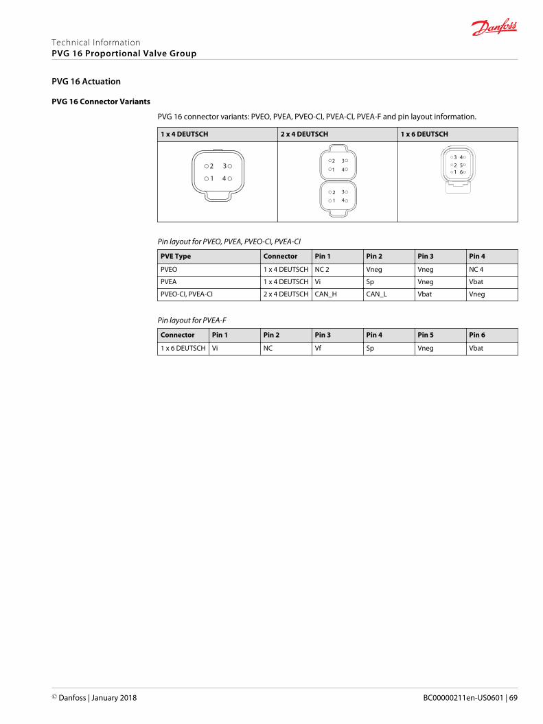
PVG 16 Connector Variants
PVG 16 connector variants: PVEO, PVEA, PVEO-CI, PVEA-CI, PVEA-F and pin layout information.
1 x 4 DEUTSCH 2 x 4 DEUTSCH 1 x 6 DEUTSCH
2 3
41
3
412
1
2 3
4 123 4
56
Pin layout for PVEO, PVEA, PVEO-CI, PVEA-CI
PVE Type Connector Pin 1 Pin 2 Pin 3 Pin 4
PVEO 1 x 4 DEUTSCH NC 2 Vneg Vneg NC 4
PVEA 1 x 4 DEUTSCH Vi Sp Vneg Vbat
PVEO-CI, PVEA-CI 2 x 4 DEUTSCH CAN_H CAN_L Vbat Vneg
Pin layout for PVEA-F
Connector Pin 1 Pin 2 Pin 3 Pin 4 Pin 5 Pin 6
1 x 6 DEUTSCH Vi NC Vf Sp Vneg Vbat
Technical InformationPVG 16 Proportional Valve Group
PVG 16 Actuation
© Danfoss | January 2018 BC00000211en-US0601 | 69
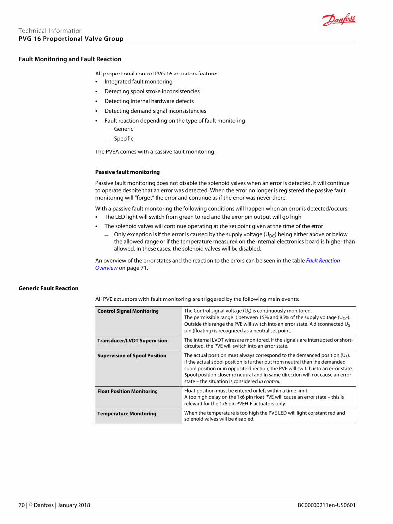
All proportional control PVG 16 actuators feature:• Integrated fault monitoring
• Detecting spool stroke inconsistencies
• Detecting internal hardware defects
• Detecting demand signal inconsistencies
• Fault reaction depending on the type of fault monitoring
‒ Generic
‒ Specific
The PVEA comes with a passive fault monitoring.
Passive fault monitoring
Passive fault monitoring does not disable the solenoid valves when an error is detected. It will continueto operate despite that an error was detected. When the error no longer is registered the passive faultmonitoring will “forget” the error and continue as if the error was never there.
With a passive fault monitoring the following conditions will happen when an error is detected/occurs:• The LED light will switch from green to red and the error pin output will go high
• The solenoid valves will continue operating at the set point given at the time of the error
‒ Only exception is if the error is caused by the supply voltage (UDC) being either above or belowthe allowed range or if the temperature measured on the internal electronics board is higher thanallowed. In these cases, the solenoid valves will be disabled.
An overview of the error states and the reaction to the errors can be seen in the table Fault ReactionOverview on page 71.
Generic Fault Reaction
All PVE actuators with fault monitoring are triggered by the following main events:
Control Signal Monitoring The Control signal voltage (US) is continuously monitored.The permissible range is between 15% and 85% of the supply voltage (UDC).Outside this range the PVE will switch into an error state. A disconnected USpin (floating) is recognized as a neutral set point.
Transducer/LVDT Supervision The internal LVDT wires are monitored. If the signals are interrupted or short-circuited, the PVE will switch into an error state.
Supervision of Spool Position The actual position must always correspond to the demanded position (US).If the actual spool position is further out from neutral than the demandedspool position or in opposite direction, the PVE will switch into an error state.Spool position closer to neutral and in same direction will not cause an errorstate – the situation is considered in control.
Float Position Monitoring Float position must be entered or left within a time limit.A too high delay on the 1x6 pin float PVE will cause an error state – this isrelevant for the 1x6 pin PVEH-F actuators only.
Temperature Monitoring When the temperature is too high the PVE LED will light constant red andsolenoid valves will be disabled.
Technical InformationPVG 16 Proportional Valve Group
Fault Monitoring and Fault Reaction
70 | © Danfoss | January 2018 BC00000211en-US0601
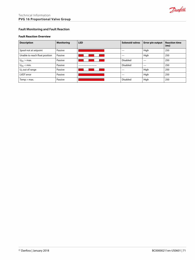
Fault Reaction Overview
Description Monitoring LED Solenoid valves Error pin output Reaction time(ms)
Spool not at setpoint Passive — High 250
Unable to reach float position Passive — High 250
UDC > max. Passive Disabled — 250
UDC < min. Passive ——————— Disabled — 250
US out of range Passive — High 250
LVDT error Passive — High 250
Temp > max. Passive Disabled High 250
Technical InformationPVG 16 Proportional Valve Group
Fault Monitoring and Fault Reaction
© Danfoss | January 2018 BC00000211en-US0601 | 71
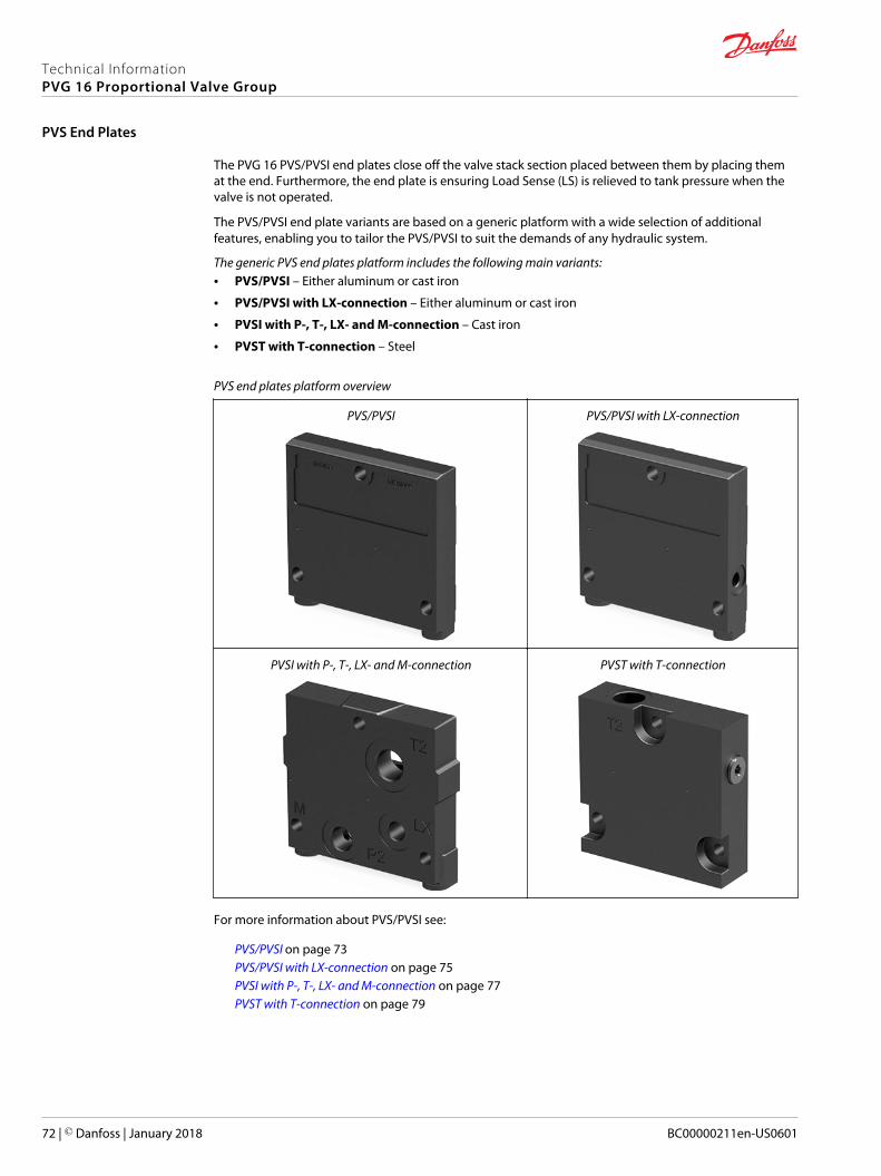
The PVG 16 PVS/PVSI end plates close off the valve stack section placed between them by placing themat the end. Furthermore, the end plate is ensuring Load Sense (LS) is relieved to tank pressure when thevalve is not operated.
The PVS/PVSI end plate variants are based on a generic platform with a wide selection of additionalfeatures, enabling you to tailor the PVS/PVSI to suit the demands of any hydraulic system.
The generic PVS end plates platform includes the following main variants:• PVS/PVSI – Either aluminum or cast iron
• PVS/PVSI with LX-connection – Either aluminum or cast iron
• PVSI with P-, T-, LX- and M-connection – Cast iron
• PVST with T-connection – Steel
PVS end plates platform overview
PVS/PVSI PVS/PVSI with LX-connection
PVSI with P-, T-, LX- and M-connection PVST with T-connection
For more information about PVS/PVSI see:
PVS/PVSI on page 73PVS/PVSI with LX-connection on page 75PVSI with P-, T-, LX- and M-connection on page 77PVST with T-connection on page 79
Technical InformationPVG 16 Proportional Valve Group
PVS End Plates
72 | © Danfoss | January 2018 BC00000211en-US0601
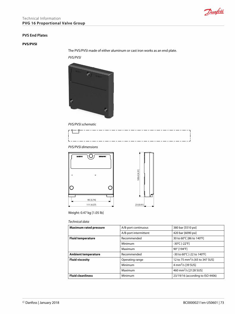
PVS/PVSI
The PVS/PVSI made of either aluminum or cast iron works as an end plate.
PVS/PVSI
PVS/PVSI schematic
PVS/PVSI dimensions
109.
4 [4
.31]
111 [4.37]
95 [3.74]
23 [0.91]
Weight: 0.47 kg [1.05 lb]
Technical data
Maximum rated pressure A/B-port continuous 380 bar [5510 psi]
A/B-port intermittent 420 bar [6090 psi]
Fluid temperature Recommended 30 to 60°C [86 to 140°F]
Minimum -30°C [-22°F]
Maximum 90° [194°F]
Ambient temperature Recommended -30 to 60°C [-22 to 140°F]
Fluid viscosity Operating range 12 to 75 mm2/s [65 to 347 SUS]
Minimum 4 mm2/s [39 SUS]
Maximum 460 mm2/s [2128 SUS]
Fluid cleanliness Minimum 23/19/16 (according to ISO 4406)
Technical InformationPVG 16 Proportional Valve Group
PVS End Plates
© Danfoss | January 2018 BC00000211en-US0601 | 73
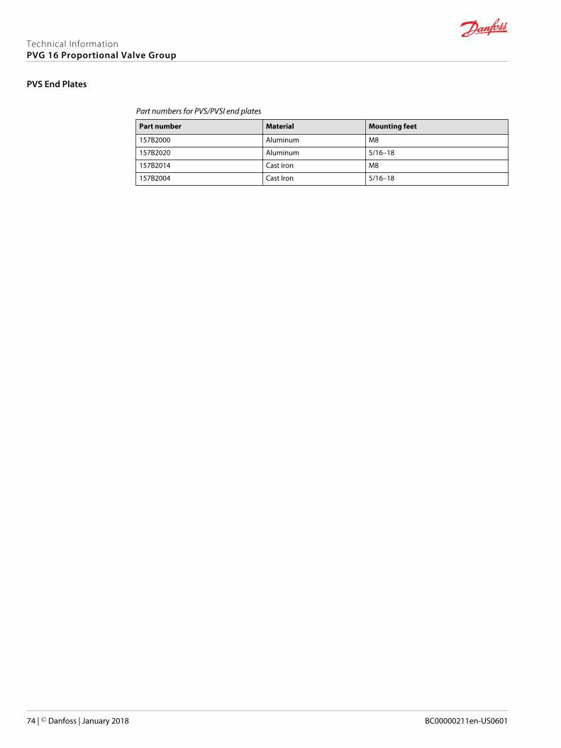
Part numbers for PVS/PVSI end plates
Part number Material Mounting feet
157B2000 Aluminum M8
157B2020 Aluminum 5/16–18
157B2014 Cast iron M8
157B2004 Cast Iron 5/16–18
Technical InformationPVG 16 Proportional Valve Group
PVS End Plates
74 | © Danfoss | January 2018 BC00000211en-US0601
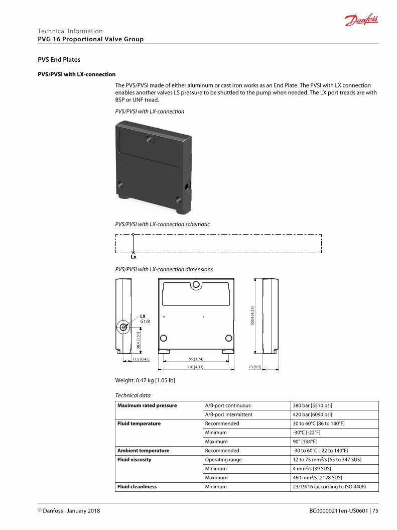
PVS/PVSI with LX-connection
The PVS/PVSI made of either aluminum or cast iron works as an End Plate. The PVSI with LX connectionenables another valves LS pressure to be shuttled to the pump when needed. The LX port treads are withBSP or UNF tread.
PVS/PVSI with LX-connection
PVS/PVSI with LX-connection schematic
Lx
PVS/PVSI with LX-connection dimensions
109.
4 [4
.31]
38.4
[1.5
1]
110 [4.33]
95 [3.74]
23 [0.9]
11.5 [0.45]
LXG1/8
Weight: 0.47 kg [1.05 lb]
Technical data
Maximum rated pressure A/B-port continuous 380 bar [5510 psi]
A/B-port intermittent 420 bar [6090 psi]
Fluid temperature Recommended 30 to 60°C [86 to 140°F]
Minimum -30°C [-22°F]
Maximum 90° [194°F]
Ambient temperature Recommended -30 to 60°C [-22 to 140°F]
Fluid viscosity Operating range 12 to 75 mm2/s [65 to 347 SUS]
Minimum 4 mm2/s [39 SUS]
Maximum 460 mm2/s [2128 SUS]
Fluid cleanliness Minimum 23/19/16 (according to ISO 4406)
Technical InformationPVG 16 Proportional Valve Group
PVS End Plates
© Danfoss | January 2018 BC00000211en-US0601 | 75

Part numbers for PVS/PVSI with LX-connection end plates
Part number Material LX-port Mounting feet
157B2011 Aluminum G1/8 M8
157B2021 Aluminum 3/8–24 5/16–18
157B2015 Cast iron G1/4 M8
157B2005 Cast Iron 1/2–20 5/16–18
Technical InformationPVG 16 Proportional Valve Group
PVS End Plates
76 | © Danfoss | January 2018 BC00000211en-US0601
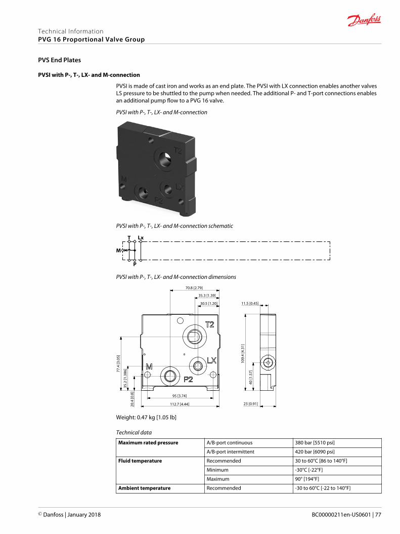
PVSI with P-, T-, LX- and M-connection
PVSI is made of cast iron and works as an end plate. The PVSI with LX connection enables another valvesLS pressure to be shuttled to the pump when needed. The additional P- and T-port connections enablesan additional pump flow to a PVG 16 valve.
PVSI with P-, T-, LX- and M-connection
PVSI with P-, T-, LX- and M-connection schematic
T Lx
M
P
PVSI with P-, T-, LX- and M-connection dimensions
77.4
[3.0
5]
11.5 [0.45]
70.8 [2.79]
35.2
[1.3
86]
35.3 [1.39]
30.5 [1.20]
20.4
[0.8
]
109.
4 [4
.31]
40 [1
.57]
112.7 [4.44]
95 [3.74]
23 [0.91]
Weight: 0.47 kg [1.05 lb]
Technical data
Maximum rated pressure A/B-port continuous 380 bar [5510 psi]
A/B-port intermittent 420 bar [6090 psi]
Fluid temperature Recommended 30 to 60°C [86 to 140°F]
Minimum -30°C [-22°F]
Maximum 90° [194°F]
Ambient temperature Recommended -30 to 60°C [-22 to 140°F]
Technical InformationPVG 16 Proportional Valve Group
PVS End Plates
© Danfoss | January 2018 BC00000211en-US0601 | 77
Technical data (continued)
Fluid viscosity Operating range 12 to 75 mm2/s [65 to 347 SUS]
Minimum 4 mm2/s [39 SUS]
Maximum 460 mm2/s [2128 SUS]
Fluid cleanliness Minimum 23/19/16 (according to ISO 4406)
Part number for PVSI with P-, T-, LX-, M-ports
Part number P-port T-port LX-port M-port Mounting feet
157B2920 G3/8 G1/2 G1/8 G1/4 M8
Technical InformationPVG 16 Proportional Valve Group
PVS End Plates
78 | © Danfoss | January 2018 BC00000211en-US0601
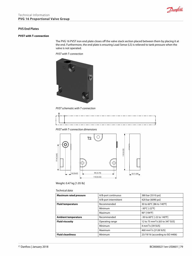
PVST with T-connection
The PVG 16 PVST iron end plate closes off the valve stack section placed between them by placing it atthe end. Furthermore, the end plate is ensuring Load Sense (LS) is relieved to tank pressure when thevalve is not operated.
PVST with T-connection
PVST schematic with T-connection
T
PVST with T-connection dimensions
77.4
[3.0
5]
110 [4.33]
110
[4.3
3]
95 [3.74]16 [0.63] 32 [1.26]
Weight: 0.47 kg [1.05 lb]
Technical data
Maximum rated pressure A/B-port continuous 380 bar [5510 psi]
A/B-port intermittent 420 bar [6090 psi]
Fluid temperature Recommended 30 to 60°C [86 to 140°F]
Minimum -30°C [-22°F]
Maximum 90° [194°F]
Ambient temperature Recommended -30 to 60°C [-22 to 140°F]
Fluid viscosity Operating range 12 to 75 mm2/s [65 to 347 SUS]
Minimum 4 mm2/s [39 SUS]
Maximum 460 mm2/s [2128 SUS]
Fluid cleanliness Minimum 23/19/16 (according to ISO 4406)
Technical InformationPVG 16 Proportional Valve Group
PVS End Plates
© Danfoss | January 2018 BC00000211en-US0601 | 79
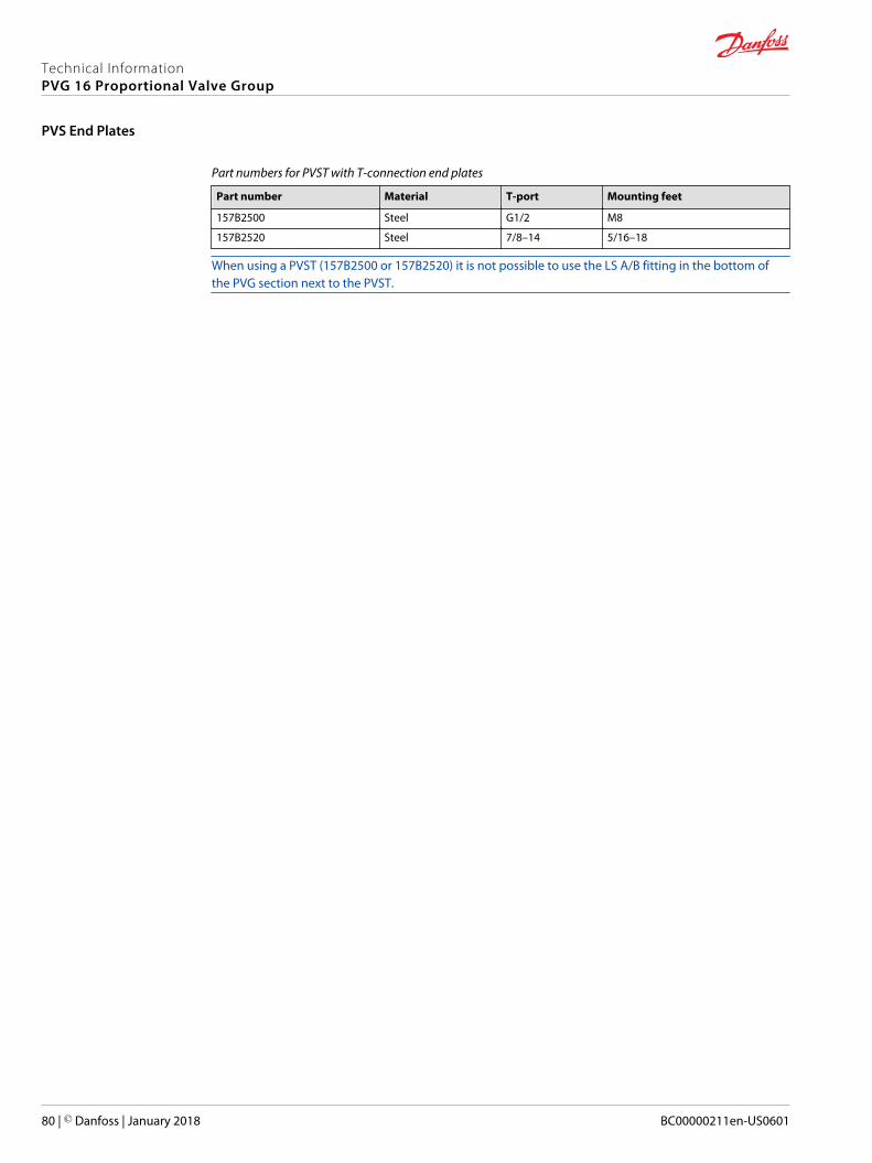
Part numbers for PVST with T-connection end plates
Part number Material T-port Mounting feet
157B2500 Steel G1/2 M8
157B2520 Steel 7/8–14 5/16–18
When using a PVST (157B2500 or 157B2520) it is not possible to use the LS A/B fitting in the bottom ofthe PVG section next to the PVST.
Technical InformationPVG 16 Proportional Valve Group
PVS End Plates
80 | © Danfoss | January 2018 BC00000211en-US0601
PVAS Stay Bolts kit for various PVG combinations consist of three tie rods, six washers, six nuts and O-ring.Use the guide and reference tables how to choose PVAS kit.
The tie rods are inserted through the entire length of the PVG valve stack. The nuts are tightened at thepump side and at the end plate.
To find the PVAS kit that fits your PVG 16 valve stack, you need to go to the table PVG 16 modules totallength and weight on page 82 and find the length. Then go to the table PVAS Part Numbers on page 82and find the matching part number.
For stay bolts for a PVG 32/16 combination, see this PVG 32/16 Combinations on page 83.
Stay bolts for PVG 256/128/32/16 combinations consist of two different kits. See PVG 256/128/32/16Combinations on page 84 to find the right kits for your combination.
Combinations with PVG 100 and PVG 120 requires special PVAS kits. These are not included in the PVAStable.
Technical InformationPVG 16 Proportional Valve Group
PVAS Stay Bolts
© Danfoss | January 2018 BC00000211en-US0601 | 81

PVAS Part Numbers
PVAS part numbers according to accumulated length interval PVG 16.
PVAS part numbers
Length, mm [in] Part number Length, mm [in] Part number
20 – 48 [0.79 – 1.89] 11188219 361 – 372 [14.21 – 14.65] 11188205
49 – 60 [1.93 – 2.36] 11188218 373 – 384 [14.69 – 15.12] 157B8026
61 – 72 [2.40 – 2.83] 157B8000 385 – 396 [15.16 – 15.59] 11188204
73 – 84 [2.87 – 3.31] 11188217 397 – 408 [15.63 – 16.06] 157B8007
85 – 96 [3.35 – 3.78] 157B8031 409 – 420 [16.10 – 16.54] 11188203
97 – 108 [3.82 – 4.25] 11188216 421 – 432 [16.58 – 17.01] 157B8027
109 – 120 [4.29 – 4.72] 157B8001 433 – 444 [17.05 – 17.48] 11188202
121 – 132 [4.76 – 5.20] 11188215 445 – 456 [17.52 – 17.95] 157B8008
133 – 144 [5.24 – 5.67] 157B8021 457 – 468 [17.99 – 18.43] 11188201
145 – 156 [5.71 – 6.14] 11188214 469 – 480 [18.47 – 18.90] 157B8028
157 – 168 [6.18 – 6.61] 157B8002 481 - 492 [18.94 – 19.37] 11188200
169 – 180 [6.65 – 7.09] 11188213 493 – 504 [19.41 – 19.84] 157B8009
181 – 192 [7.13 – 7.56] 157B8022 505 – 516 [19.88 – 20.31] 11188199
193 – 204 [7.60 – 8.03] 11188212 517 – 528 [20.35 – 20.79] 157B8029
205 – 216 [8.07 – 8.50] 157B8003 529 – 540 [20.83 – 21.26] 11188198
217 – 228 [8.54 – 8.98] 11188211 541 – 552 [21.30 – 21.73] 157B8010
229 – 240 [9.02 – 9.45] 157B8023 553 – 564 [21.77 - 22.20] 11188197
241 – 252 [9.49 – 9.92] 11188210 565 – 576 [22.24 – 22.68] 157B8030
253 – 264 [9.96 – 10.39] 157B8004 577 – 588 [22.72 – 23.15] 11188196
265 – 276 [10.43 – 10.87] 11188209 589 – 600 [23.19 – 23.62] 157B8061
277 – 288 [10.91 – 11.34] 157B8024 601 – 612 [23.66 – 24.09] 11188195
289 – 300 [11.38 – 11.81] 11188208 613 – 624 [24.13 – 24.57] 157B8081
301 – 312 [11.85 – 12.28] 157B8005 625 – 636 [24.61 – 25.04] 11188194
313 – 324 [12.32 – 12.76] 11188207 637 – 648 [25.08 – 25.51] 157B8062
325 – 336 [12.80 – 13.23] 157B8025 649 – 660 [25.55 – 25.98] 11188189
337 – 348 [13.27 – 13.70] 11188206 661 - 672 [26.02 – 26.46] 157B8082
349 – 360 [13.74 – 14.17] 157B8006
PVG 16 modules total length and weight
The table of PVB 16 modules consists of total length depending on the amount of valve groups withweight.
No. ofPVB 16
1 2 3 4 5 6 7 8 9 10 11 12
Lengthmm [in]
140[5.51]
189[7.44]
213[8.39]
262[10.31]
311[12.24]
336[13.23]
385[15.16]
434[17.09]
458[18.03]
507[19.96]
551[21.69]
576[22.68]
Weight*
kg [lb]7,2[15.9]
10,9[24]
14,6[32.2]
18,3[40.3]
22[48.5]
25,7[56.7]
29,4[64.8]
33,1[73]
36,8[81.1]
40,5[89.3]
44,2[97.4]
47,9[105.6]
* Weight is for a PVG 16 with a PVE on each working section and is only approximate.
Technical InformationPVG 16 Proportional Valve Group
PVAS Stay Bolts
82 | © Danfoss | January 2018 BC00000211en-US0601
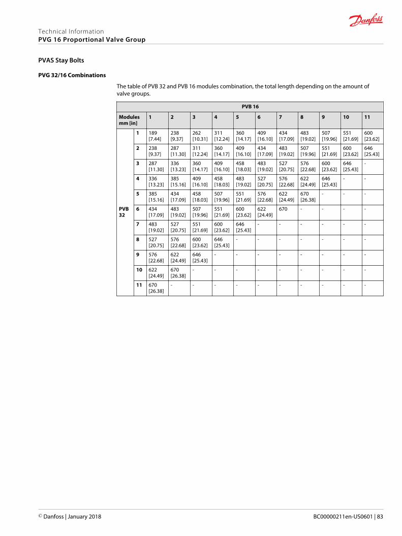
PVG 32/16 Combinations
The table of PVB 32 and PVB 16 modules combination, the total length depending on the amount ofvalve groups.
PVB 16
Modulesmm [in]
1 2 3 4 5 6 7 8 9 10 11
PVB32
1 189[7.44]
238[9.37]
262[10.31]
311[12.24]
360[14.17]
409[16.10]
434[17.09]
483[19.02]
507[19.96]
551[21.69]
600[23.62]
2 238[9.37]
287[11.30]
311[12.24]
360[14.17]
409[16.10]
434[17.09]
483[19.02]
507[19.96]
551[21.69]
600[23.62]
646[25.43]
3 287[11.30]
336[13.23]
360[14.17]
409[16.10]
458[18.03]
483[19.02]
527[20.75]
576[22.68]
600[23.62]
646[25.43]
-
4 336[13.23]
385[15.16]
409[16.10]
458[18.03]
483[19.02]
527[20.75]
576[22.68]
622[24.49]
646[25.43]
- -
5 385[15.16]
434[17.09]
458[18.03]
507[19.96]
551[21.69]
576[22.68]
622[24.49]
670[26.38]
- - -
6 434[17.09]
483[19.02]
507[19.96]
551[21.69]
600[23.62]
622[24.49]
670 - - - -
7 483[19.02]
527[20.75]
551[21.69]
600[23.62]
646[25.43]
- - - - - -
8 527[20.75]
576[22.68]
600[23.62]
646[25.43]
- - - - - - -
9 576[22.68]
622[24.49]
646[25.43]
- - - - - - - -
10 622[24.49]
670[26.38]
- - - - - - - - -
11 670[26.38]
- - - - - - - - - -
Technical InformationPVG 16 Proportional Valve Group
PVAS Stay Bolts
© Danfoss | January 2018 BC00000211en-US0601 | 83
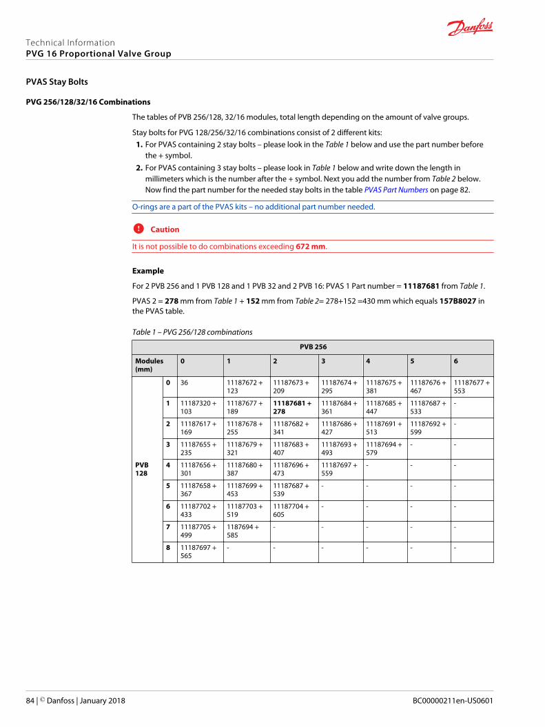
PVG 256/128/32/16 Combinations
The tables of PVB 256/128, 32/16 modules, total length depending on the amount of valve groups.
Stay bolts for PVG 128/256/32/16 combinations consist of 2 different kits:1. For PVAS containing 2 stay bolts – please look in the Table 1 below and use the part number before
the + symbol.2. For PVAS containing 3 stay bolts – please look in Table 1 below and write down the length in
millimeters which is the number after the + symbol. Next you add the number from Table 2 below.Now find the part number for the needed stay bolts in the table PVAS Part Numbers on page 82.
O-rings are a part of the PVAS kits – no additional part number needed.
C Caution
It is not possible to do combinations exceeding 672 mm.
Example
For 2 PVB 256 and 1 PVB 128 and 1 PVB 32 and 2 PVB 16: PVAS 1 Part number = 11187681 from Table 1.
PVAS 2 = 278 mm from Table 1 + 152 mm from Table 2= 278+152 =430 mm which equals 157B8027 inthe PVAS table.
Table 1 – PVG 256/128 combinations
PVB 256
Modules(mm)
0 1 2 3 4 5 6
PVB128
0 36 11187672 +123
11187673 +209
11187674 +295
11187675 +381
11187676 +467
11187677 +553
1 11187320 +103
11187677 +189
11187681 +278
11187684 +361
11187685 +447
11187687 +533
-
2 11187617 +169
11187678 +255
11187682 +341
11187686 +427
11187691 +513
11187692 +599
-
3 11187655 +235
11187679 +321
11187683 +407
11187693 +493
11187694 +579
- -
4 11187656 +301
11187680 +387
11187696 +473
11187697 +559
- - -
5 11187658 +367
11187699 +453
11187687 +539
- - - -
6 11187702 +433
11187703 +519
11187704 +605
- - - -
7 11187705 +499
1187694 +585
- - - - -
8 11187697 +565
- - - - - -
Technical InformationPVG 16 Proportional Valve Group
PVAS Stay Bolts
84 | © Danfoss | January 2018 BC00000211en-US0601
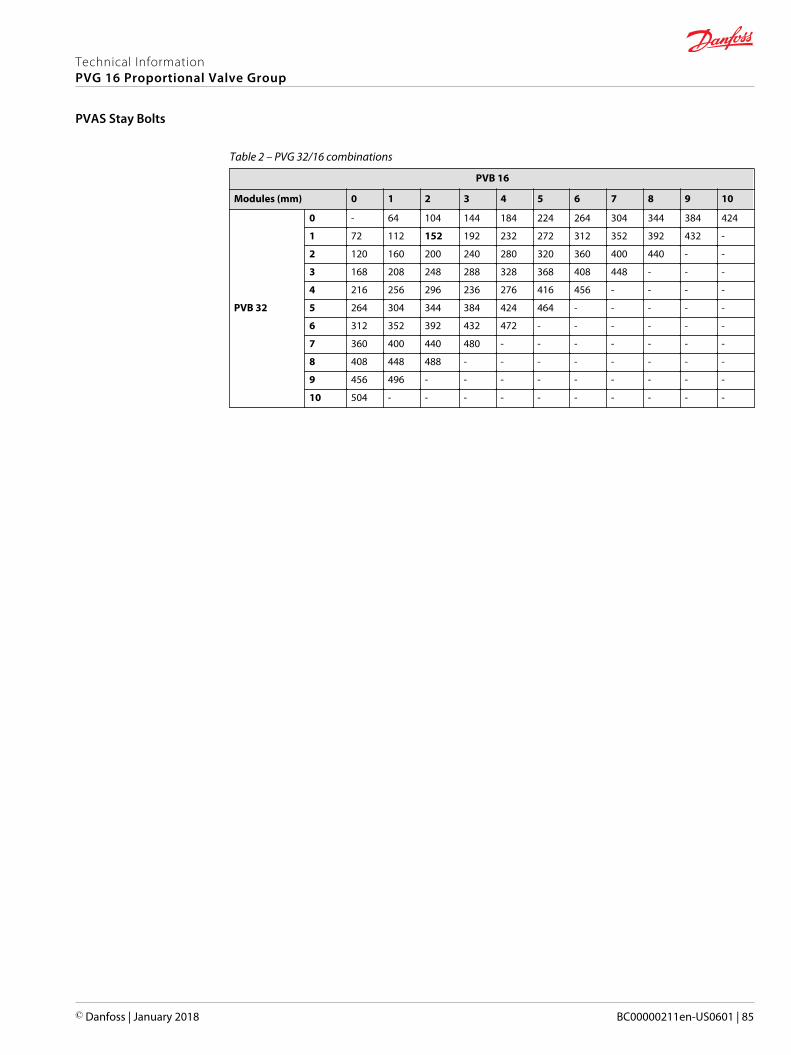
Table 2 – PVG 32/16 combinations
PVB 16
Modules (mm) 0 1 2 3 4 5 6 7 8 9 10
PVB 32
0 - 64 104 144 184 224 264 304 344 384 424
1 72 112 152 192 232 272 312 352 392 432 -
2 120 160 200 240 280 320 360 400 440 - -
3 168 208 248 288 328 368 408 448 - - -
4 216 256 296 236 276 416 456 - - - -
5 264 304 344 384 424 464 - - - - -
6 312 352 392 432 472 - - - - - -
7 360 400 440 480 - - - - - - -
8 408 448 488 - - - - - - - -
9 456 496 - - - - - - - - -
10 504 - - - - - - - - - -
Technical InformationPVG 16 Proportional Valve Group
PVAS Stay Bolts
© Danfoss | January 2018 BC00000211en-US0601 | 85
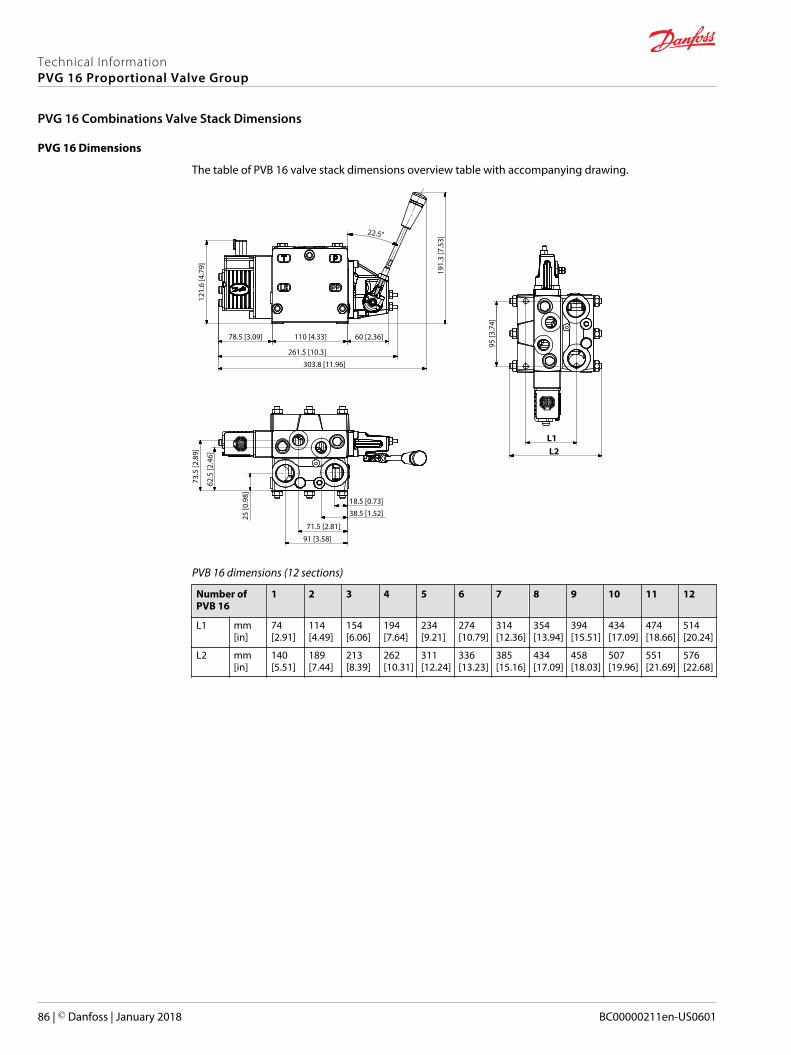
PVG 16 Dimensions
The table of PVB 16 valve stack dimensions overview table with accompanying drawing.
L1
91 [3.58]
71.5 [2.81]
38.5 [1.52]
18.5 [0.73]
261.5 [10.3]
78.5 [3.09] 110 [4.33]
303.8 [11.96]
22.5°
60 [2.36]
95 [3
.74]
191.
3 [7
.53]
121.
6 [4
.79]
73.5
[2.8
9]
62.5
[2.4
6]
25 [0
.98]
L2
PVB 16 dimensions (12 sections)
Number ofPVB 16
1 2 3 4 5 6 7 8 9 10 11 12
L1 mm[in]
74[2.91]
114[4.49]
154[6.06]
194[7.64]
234[9.21]
274[10.79]
314[12.36]
354[13.94]
394[15.51]
434[17.09]
474[18.66]
514[20.24]
L2 mm[in]
140[5.51]
189[7.44]
213[8.39]
262[10.31]
311[12.24]
336[13.23]
385[15.16]
434[17.09]
458[18.03]
507[19.96]
551[21.69]
576[22.68]
Technical InformationPVG 16 Proportional Valve Group
PVG 16 Combinations Valve Stack Dimensions
86 | © Danfoss | January 2018 BC00000211en-US0601
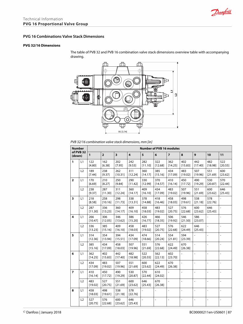
PVG 32/16 Dimensions
The table of PVB 32 and PVB 16 combination valve stack dimensions overview table with accompanyingdrawing.
L1
95 [3.74]
L2
PVB 32/16 combination valve stack dimensions, mm [in]
Numberof PVB 32(down)
Number of PVB 16 modules
1 2 3 4 5 6 7 8 9 10 11
1 L1 122[4.80]
162[6.38]
202[7.95]
242[9.53]
282[11.10]
322[12.68]
362[14.25]
402[15.83]
442[17.40]
482[18.98]
522[20.55]
L2 189[7.44]
238[9.37]
262[10.31]
311[12.24]
360[14.17]
385[15.16]
434[17.09]
483[19.02]
507[19.96]
551[21.69]
600[23.62]
2 L1 170[6.69]
210[8.27]
250[9.84]
290[11.42]
330[12.99]
370[14.57]
410[16.14]
450[17.72]
490[19.29]
530[20.87]
570[22.44]
L2 238[9.37]
287[11.30]
311[12.24]
360[14.17]
409[16.10]
434[17.09]
483[19.02]
507[19.96]
551[21.69]
600[23.62]
646[25.43]
3 L1 218[8.58]
258[10.16]
298[11.73]
338[13.31]
378[14.88]
418[16.46]
458[18.03]
498[19.61]
538[21.18]
578[22.76]
-
L2 287[11.30]
336[13.23]
360[14.17]
409[16.10]
458[18.03]
483[19.02]
527[20.75]
576[22.68]
600[23.62]
646[25.43]
-
4 L1 266[10.47]
306[12.05]
346[13.62]
386[15.20]
426[16.77]
466[18.35]
506[19.92]
546[21.50]
586[23.07]
- -
L2 336[13.23]
385[15.16]
409[16.10]
458[18.03]
483[19.02]
527[20.75]
576[22.68]
622[24.49]
646[25.43]
- -
5 L1 314[12.36]
354[13.94]
394[15.51]
434[17.09]
474[18.66]
514[20.24]
554[21.81]
594[23.39]
- - -
L2 385[15.16]
434[17.09]
458[18.03]
507[19.96]
551[21.69]
576[22.68]
622[24.49]
670[26.38]
- - -
6 L1 362[14.25]
402[15.83]
442[17.40]
482[18.98]
522[20.55]
562[22.13]
602[23.70]
- - - -
L2 434[17.09]
483[19.02]
507[19.96]
551[21.69]
600[23.62]
622[24.49]
670[26.38]
- - - -
7 L1 410[16.14]
450[17.72]
490[19.29]
530[20.87]
570[22.44]
610[24.02]
- - - - -
L2 483[19.02]
527[20.75]
551[21.69]
600[23.62]
646[25.43]
670[26.38]
- - - - -
8 L1 458[18.03]
498[19.61]
538[21.18]
578[22.76]
- - - - - - -
L2 527[20.75]
576[22.68]
600[23.62]
646[25.43]
- - - - - - -
Technical InformationPVG 16 Proportional Valve Group
PVG 16 Combinations Valve Stack Dimensions
© Danfoss | January 2018 BC00000211en-US0601 | 87
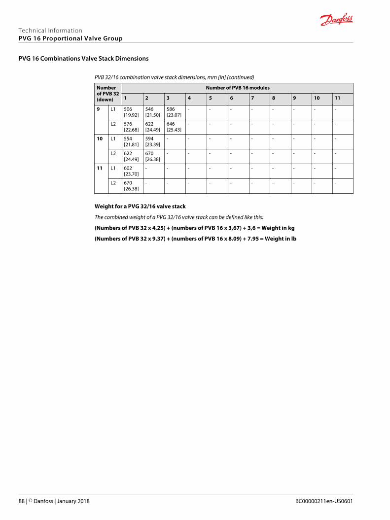
PVB 32/16 combination valve stack dimensions, mm [in] (continued)
Numberof PVB 32(down)
Number of PVB 16 modules
1 2 3 4 5 6 7 8 9 10 11
9 L1 506[19.92]
546[21.50]
586[23.07]
- - - - - - - -
L2 576[22.68]
622[24.49]
646[25.43]
- - - - - - - -
10 L1 554[21.81]
594[23.39]
- - - - - - - - -
L2 622[24.49]
670[26.38]
- - - - - - - - -
11 L1 602[23.70]
- - - - - - - - - -
L2 670[26.38]
- - - - - - - - - -
Weight for a PVG 32/16 valve stack
The combined weight of a PVG 32/16 valve stack can be defined like this:
(Numbers of PVB 32 x 4,25) + (numbers of PVB 16 x 3,67) + 3,6 = Weight in kg
(Numbers of PVB 32 x 9.37) + (numbers of PVB 16 x 8.09) + 7.95 = Weight in lb
Technical InformationPVG 16 Proportional Valve Group
PVG 16 Combinations Valve Stack Dimensions
88 | © Danfoss | January 2018 BC00000211en-US0601
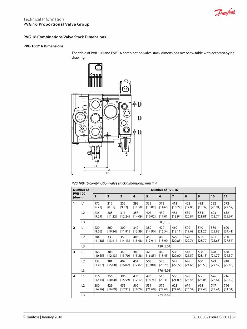
PVG 100/16 Dimensions
The table of PVB 100 and PVB 16 combination valve stack dimensions overview table with accompanyingdrawing.
L1L2
L3
PVB 100/16 combination valve stack dimensions, mm [in]
Number ofPVB 100(down)
Number of PVB 16
1 2 3 4 5 6 7 8 9 10 11
1 L1 172[6.77]
212[8.35]
252[9.92]
292[11.50]
332[13.07]
372[14.65]
412[16.22]
452[17.80]
492[19.37]
532[20.94]
572[22.52]
L2 236[9.29]
285[11.22]
311[12.24]
358[14.09]
407[16.02]
432[17.01]
481[18.94]
530[20.87]
554[21.81]
603[23.74]
652[25.67]
L3 80 [3.15]
2 L1 220[8.66]
260[10.24]
300[11.81]
340[13.39]
380[14.96]
420[16.54]
460[18.11]
500[19.69]
540[21.26]
580[22.83]
620[24.41]
L2 284[11.18]
333[13.11]
359[14.13]
406[15.98]
455[17.91]
480[18.90]
529[20.83]
578[22.76]
602[23.70]
651[25.63]
700[27.56]
L3 128 [5.04]
3 L1 268[10.55]
308[12.13]
348[13.70]
388[15.28]
428[16.85]
468[18.43]
508[20.00]
548[21.57]
588[23.15]
628[24.72]
668[26.30]
L2 332[13.07]
381[15.00]
407[16.02]
454[17.87]
503[19.80]
528[20.79]
577[22.72]
626[24.65]
650[25.59]
699[27.52]
748[29.45]
L3 176 [6.93]
4 L1 316[12.44]
256[10.08]
396[15.59]
436[17.17]
476[18.74]
516[20.31]
556[21.89]
596[23.46]
636[25.04]
676[26.61]
716[28.19]
L2 380[14.96]
429[16.89]
455[17.91]
502[19.76]
551[21.69]
576[22.68]
625[24.61]
674[26.54]
698[27.48]
747[29.41]
796[31.34]
L3 224 [8.82]
Technical InformationPVG 16 Proportional Valve Group
PVG 16 Combinations Valve Stack Dimensions
© Danfoss | January 2018 BC00000211en-US0601 | 89
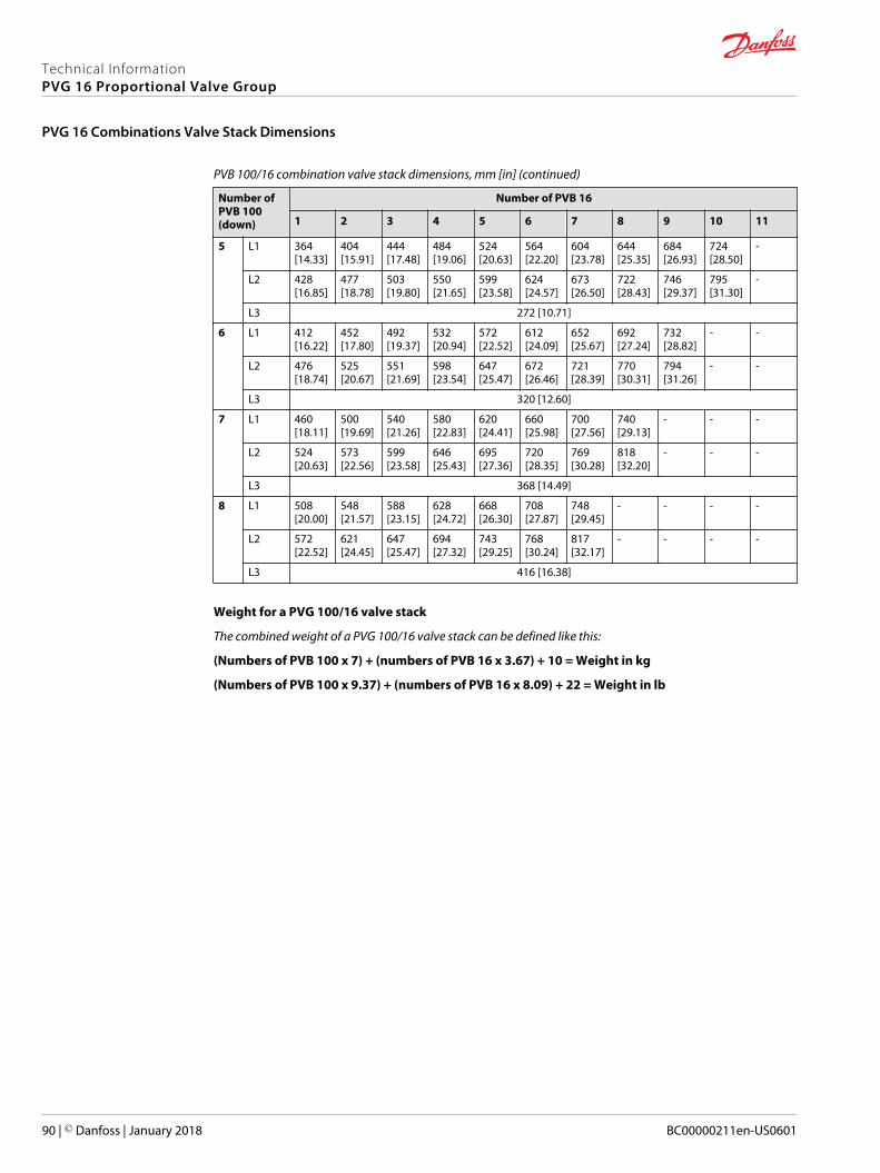
PVB 100/16 combination valve stack dimensions, mm [in] (continued)
Number ofPVB 100(down)
Number of PVB 16
1 2 3 4 5 6 7 8 9 10 11
5 L1 364[14.33]
404[15.91]
444[17.48]
484[19.06]
524[20.63]
564[22.20]
604[23.78]
644[25.35]
684[26.93]
724[28.50]
-
L2 428[16.85]
477[18.78]
503[19.80]
550[21.65]
599[23.58]
624[24.57]
673[26.50]
722[28.43]
746[29.37]
795[31.30]
-
L3 272 [10.71]
6 L1 412[16.22]
452[17.80]
492[19.37]
532[20.94]
572[22.52]
612[24.09]
652[25.67]
692[27.24]
732[28.82]
- -
L2 476[18.74]
525[20.67]
551[21.69]
598[23.54]
647[25.47]
672[26.46]
721[28.39]
770[30.31]
794[31.26]
- -
L3 320 [12.60]
7 L1 460[18.11]
500[19.69]
540[21.26]
580[22.83]
620[24.41]
660[25.98]
700[27.56]
740[29.13]
- - -
L2 524[20.63]
573[22.56]
599[23.58]
646[25.43]
695[27.36]
720[28.35]
769[30.28]
818[32.20]
- - -
L3 368 [14.49]
8 L1 508[20.00]
548[21.57]
588[23.15]
628[24.72]
668[26.30]
708[27.87]
748[29.45]
- - - -
L2 572[22.52]
621[24.45]
647[25.47]
694[27.32]
743[29.25]
768[30.24]
817[32.17]
- - - -
L3 416 [16.38]
Weight for a PVG 100/16 valve stack
The combined weight of a PVG 100/16 valve stack can be defined like this:
(Numbers of PVB 100 x 7) + (numbers of PVB 16 x 3.67) + 10 = Weight in kg
(Numbers of PVB 100 x 9.37) + (numbers of PVB 16 x 8.09) + 22 = Weight in lb
Technical InformationPVG 16 Proportional Valve Group
PVG 16 Combinations Valve Stack Dimensions
90 | © Danfoss | January 2018 BC00000211en-US0601
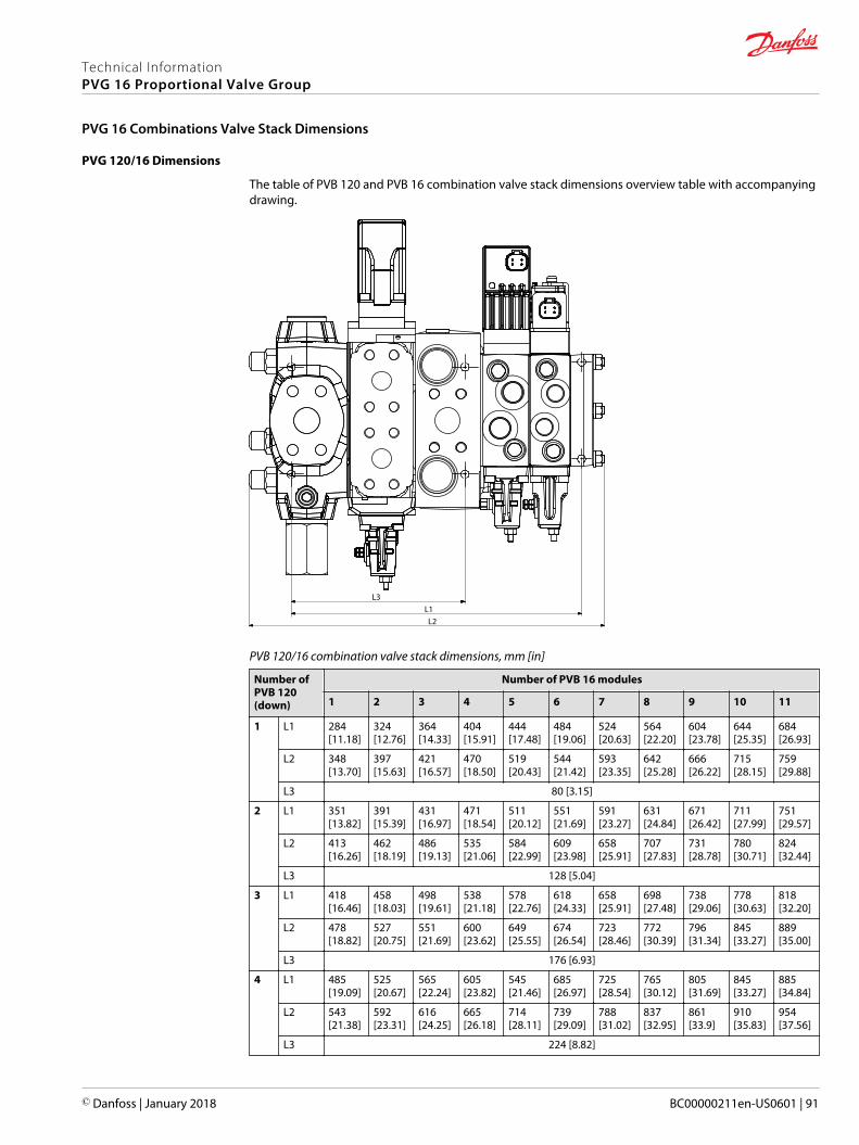
PVG 120/16 Dimensions
The table of PVB 120 and PVB 16 combination valve stack dimensions overview table with accompanyingdrawing.
L1L2
L3
PVB 120/16 combination valve stack dimensions, mm [in]
Number ofPVB 120(down)
Number of PVB 16 modules
1 2 3 4 5 6 7 8 9 10 11
1 L1 284[11.18]
324[12.76]
364[14.33]
404[15.91]
444[17.48]
484[19.06]
524[20.63]
564[22.20]
604[23.78]
644[25.35]
684[26.93]
L2 348[13.70]
397[15.63]
421[16.57]
470[18.50]
519[20.43]
544[21.42]
593[23.35]
642[25.28]
666[26.22]
715[28.15]
759[29.88]
L3 80 [3.15]
2 L1 351[13.82]
391[15.39]
431[16.97]
471[18.54]
511[20.12]
551[21.69]
591[23.27]
631[24.84]
671[26.42]
711[27.99]
751[29.57]
L2 413[16.26]
462[18.19]
486[19.13]
535[21.06]
584[22.99]
609[23.98]
658[25.91]
707[27.83]
731[28.78]
780[30.71]
824[32.44]
L3 128 [5.04]
3 L1 418[16.46]
458[18.03]
498[19.61]
538[21.18]
578[22.76]
618[24.33]
658[25.91]
698[27.48]
738[29.06]
778[30.63]
818[32.20]
L2 478[18.82]
527[20.75]
551[21.69]
600[23.62]
649[25.55]
674[26.54]
723[28.46]
772[30.39]
796[31.34]
845[33.27]
889[35.00]
L3 176 [6.93]
4 L1 485[19.09]
525[20.67]
565[22.24]
605[23.82]
545[21.46]
685[26.97]
725[28.54]
765[30.12]
805[31.69]
845[33.27]
885[34.84]
L2 543[21.38]
592[23.31]
616[24.25]
665[26.18]
714[28.11]
739[29.09]
788[31.02]
837[32.95]
861[33.9]
910[35.83]
954[37.56]
L3 224 [8.82]
Technical InformationPVG 16 Proportional Valve Group
PVG 16 Combinations Valve Stack Dimensions
© Danfoss | January 2018 BC00000211en-US0601 | 91
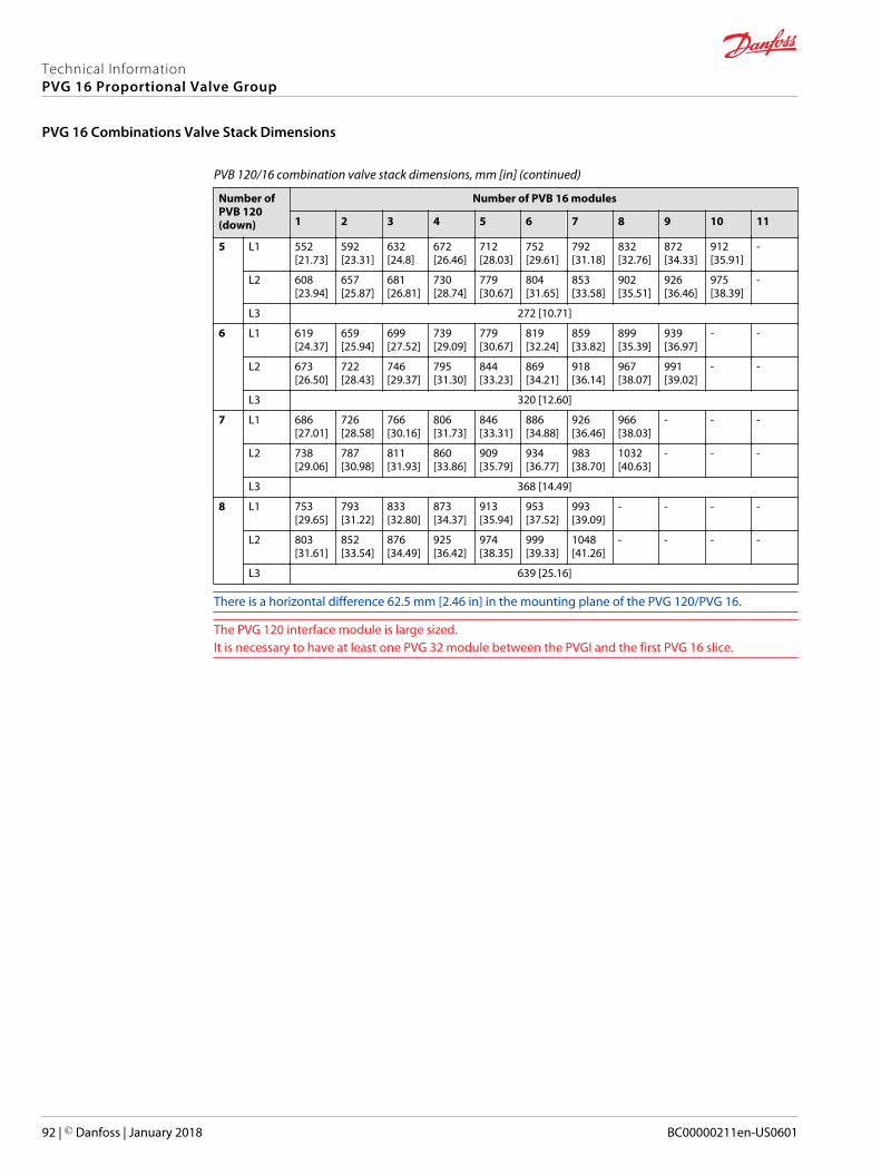
PVB 120/16 combination valve stack dimensions, mm [in] (continued)
Number ofPVB 120(down)
Number of PVB 16 modules
1 2 3 4 5 6 7 8 9 10 11
5 L1 552[21.73]
592[23.31]
632[24.8]
672[26.46]
712[28.03]
752[29.61]
792[31.18]
832[32.76]
872[34.33]
912[35.91]
-
L2 608[23.94]
657[25.87]
681[26.81]
730[28.74]
779[30.67]
804[31.65]
853[33.58]
902[35.51]
926[36.46]
975[38.39]
-
L3 272 [10.71]
6 L1 619[24.37]
659[25.94]
699[27.52]
739[29.09]
779[30.67]
819[32.24]
859[33.82]
899[35.39]
939[36.97]
- -
L2 673[26.50]
722[28.43]
746[29.37]
795[31.30]
844[33.23]
869[34.21]
918[36.14]
967[38.07]
991[39.02]
- -
L3 320 [12.60]
7 L1 686[27.01]
726[28.58]
766[30.16]
806[31.73]
846[33.31]
886[34.88]
926[36.46]
966[38.03]
- - -
L2 738[29.06]
787[30.98]
811[31.93]
860[33.86]
909[35.79]
934[36.77]
983[38.70]
1032[40.63]
- - -
L3 368 [14.49]
8 L1 753[29.65]
793[31.22]
833[32.80]
873[34.37]
913[35.94]
953[37.52]
993[39.09]
- - - -
L2 803[31.61]
852[33.54]
876[34.49]
925[36.42]
974[38.35]
999[39.33]
1048[41.26]
- - - -
L3 639 [25.16]
There is a horizontal difference 62.5 mm [2.46 in] in the mounting plane of the PVG 120/PVG 16.
The PVG 120 interface module is large sized.It is necessary to have at least one PVG 32 module between the PVGI and the first PVG 16 slice.
Technical InformationPVG 16 Proportional Valve Group
PVG 16 Combinations Valve Stack Dimensions
92 | © Danfoss | January 2018 BC00000211en-US0601
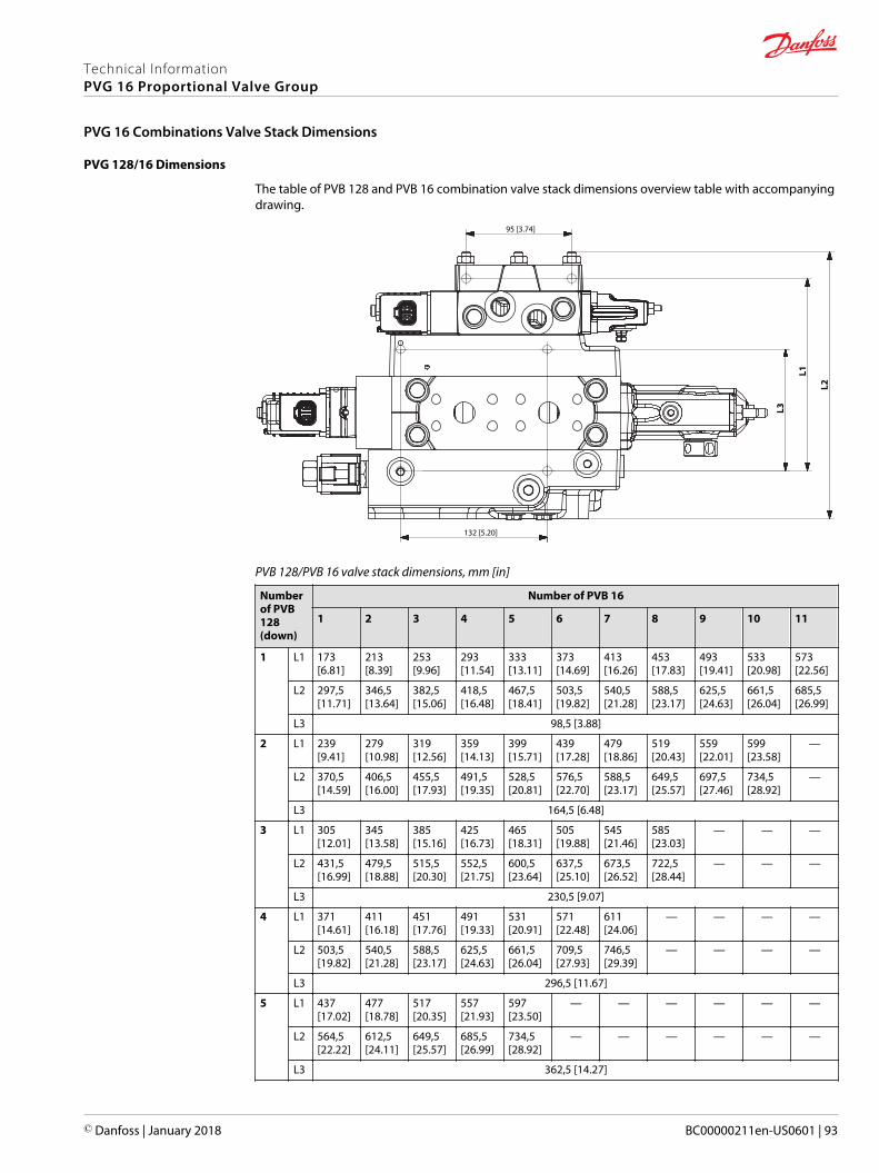
PVG 128/16 Dimensions
The table of PVB 128 and PVB 16 combination valve stack dimensions overview table with accompanyingdrawing.
L1
L3
95 [3.74]
132 [5.20]
L2
PVB 128/PVB 16 valve stack dimensions, mm [in]
Numberof PVB128(down)
Number of PVB 16
1 2 3 4 5 6 7 8 9 10 11
1 L1 173[6.81]
213[8.39]
253[9.96]
293[11.54]
333[13.11]
373[14.69]
413[16.26]
453[17.83]
493[19.41]
533[20.98]
573[22.56]
L2 297,5[11.71]
346,5[13.64]
382,5[15.06]
418,5[16.48]
467,5[18.41]
503,5[19.82]
540,5[21.28]
588,5[23.17]
625,5[24.63]
661,5[26.04]
685,5[26.99]
L3 98,5 [3.88]
2 L1 239[9.41]
279[10.98]
319[12.56]
359[14.13]
399[15.71]
439[17.28]
479[18.86]
519[20.43]
559[22.01]
599[23.58]
—
L2 370,5[14.59]
406,5[16.00]
455,5[17.93]
491,5[19.35]
528,5[20.81]
576,5[22.70]
588,5[23.17]
649,5[25.57]
697,5[27.46]
734,5[28.92]
—
L3 164,5 [6.48]
3 L1 305[12.01]
345[13.58]
385[15.16]
425[16.73]
465[18.31]
505[19.88]
545[21.46]
585[23.03]
— — —
L2 431,5[16.99]
479,5[18.88]
515,5[20.30]
552,5[21.75]
600,5[23.64]
637,5[25.10]
673,5[26.52]
722,5[28.44]
— — —
L3 230,5 [9.07]
4 L1 371[14.61]
411[16.18]
451[17.76]
491[19.33]
531[20.91]
571[22.48]
611[24.06]
— — — —
L2 503,5[19.82]
540,5[21.28]
588,5[23.17]
625,5[24.63]
661,5[26.04]
709,5[27.93]
746,5[29.39]
— — — —
L3 296,5 [11.67]
5 L1 437[17.02]
477[18.78]
517[20.35]
557[21.93]
597[23.50]
— — — — — —
L2 564,5[22.22]
612,5[24.11]
649,5[25.57]
685,5[26.99]
734,5[28.92]
— — — — — —
L3 362,5 [14.27]
Technical InformationPVG 16 Proportional Valve Group
PVG 16 Combinations Valve Stack Dimensions
© Danfoss | January 2018 BC00000211en-US0601 | 93
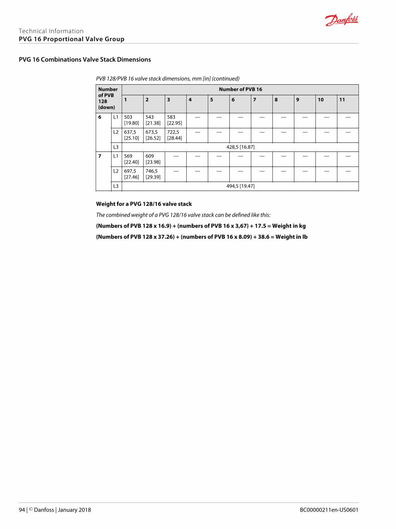
PVB 128/PVB 16 valve stack dimensions, mm [in] (continued)
Numberof PVB128(down)
Number of PVB 16
1 2 3 4 5 6 7 8 9 10 11
6 L1 503[19.80]
543[21.38]
583[22.95]
— — — — — — — —
L2 637,5[25.10]
673,5[26.52]
722,5[28.44]
— — — — — — — —
L3 428,5 [16.87]
7 L1 569[22.40]
609[23.98]
— — — — — — — — —
L2 697,5[27.46]
746,5[29.39]
— — — — — — — — —
L3 494,5 [19.47]
Weight for a PVG 128/16 valve stack
The combined weight of a PVG 128/16 valve stack can be defined like this:
(Numbers of PVB 128 x 16.9) + (numbers of PVB 16 x 3,67) + 17.5 = Weight in kg
(Numbers of PVB 128 x 37.26) + (numbers of PVB 16 x 8.09) + 38.6 = Weight in lb
Technical InformationPVG 16 Proportional Valve Group
PVG 16 Combinations Valve Stack Dimensions
94 | © Danfoss | January 2018 BC00000211en-US0601
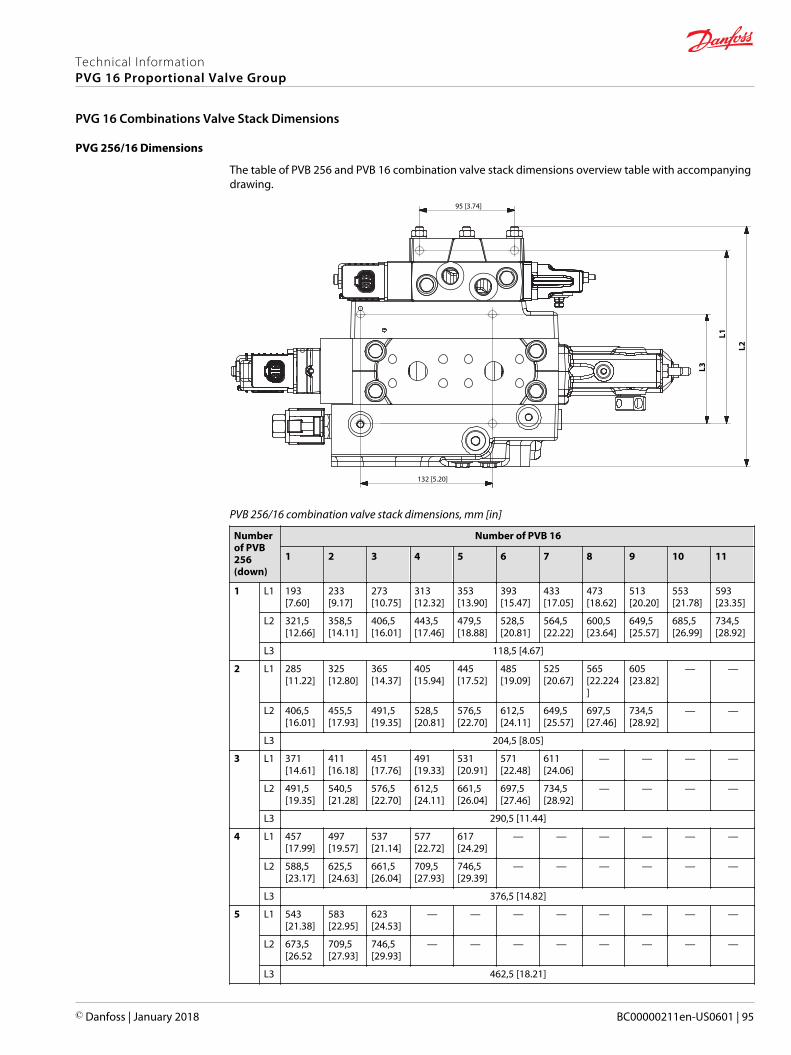
PVG 256/16 Dimensions
The table of PVB 256 and PVB 16 combination valve stack dimensions overview table with accompanyingdrawing.
L1
L3
95 [3.74]
132 [5.20]
L2
PVB 256/16 combination valve stack dimensions, mm [in]
Numberof PVB256(down)
Number of PVB 16
1 2 3 4 5 6 7 8 9 10 11
1 L1 193[7.60]
233[9.17]
273[10.75]
313[12.32]
353[13.90]
393[15.47]
433[17.05]
473[18.62]
513[20.20]
553[21.78]
593[23.35]
L2 321,5[12.66]
358,5[14.11]
406,5[16.01]
443,5[17.46]
479,5[18.88]
528,5[20.81]
564,5[22.22]
600,5[23.64]
649,5[25.57]
685,5[26.99]
734,5[28.92]
L3 118,5 [4.67]
2 L1 285[11.22]
325[12.80]
365[14.37]
405[15.94]
445[17.52]
485[19.09]
525[20.67]
565[22.224]
605[23.82]
— —
L2 406,5[16.01]
455,5[17.93]
491,5[19.35]
528,5[20.81]
576,5[22.70]
612,5[24.11]
649,5[25.57]
697,5[27.46]
734,5[28.92]
— —
L3 204,5 [8.05]
3 L1 371[14.61]
411[16.18]
451[17.76]
491[19.33]
531[20.91]
571[22.48]
611[24.06]
— — — —
L2 491,5[19.35]
540,5[21.28]
576,5[22.70]
612,5[24.11]
661,5[26.04]
697,5[27.46]
734,5[28.92]
— — — —
L3 290,5 [11.44]
4 L1 457[17.99]
497[19.57]
537[21.14]
577[22.72]
617[24.29]
— — — — — —
L2 588,5[23.17]
625,5[24.63]
661,5[26.04]
709,5[27.93]
746,5[29.39]
— — — — — —
L3 376,5 [14.82]
5 L1 543[21.38]
583[22.95]
623[24.53]
— — — — — — — —
L2 673,5[26.52
709,5[27.93]
746,5[29.93]
— — — — — — — —
L3 462,5 [18.21]
Technical InformationPVG 16 Proportional Valve Group
PVG 16 Combinations Valve Stack Dimensions
© Danfoss | January 2018 BC00000211en-US0601 | 95
Weight for a PVG 256/16 valve stack
The combined weight of a PVG 256/16 valve stack can be defined like this:
(Numbers of PVB 256 x 20.9) + (numbers of PVB 16 x 3,67) + 17.5 = Weight in kg
(Numbers of PVB 256 x 40.08) + (numbers of PVB 16 x 8.09) + 38.6 = Weight in lb
Technical InformationPVG 16 Proportional Valve Group
PVG 16 Combinations Valve Stack Dimensions
96 | © Danfoss | January 2018 BC00000211en-US0601
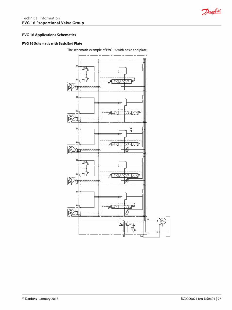
PVG 16 Schematic with Basic End Plate
The schematic example of PVG 16 with basic end plate.
A
A
B
B
A
B
A
B
A
B
LSMT
P
Technical InformationPVG 16 Proportional Valve Group
PVG 16 Applications Schematics
© Danfoss | January 2018 BC00000211en-US0601 | 97
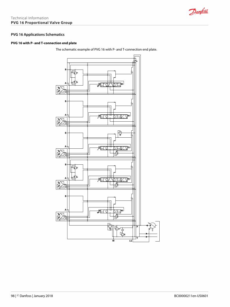
PVG 16 with P- and T-connection end plate
The schematic example of PVG 16 with P- and T-connection end plate.
A
A
B
B
LSM
M
A
B
A
B
A
B
T
P
Technical InformationPVG 16 Proportional Valve Group
PVG 16 Applications Schematics
98 | © Danfoss | January 2018 BC00000211en-US0601
Technical InformationPVG 16 Proportional Valve Group
© Danfoss | January 2018 BC00000211en-US0601 | 99
Danfoss Power Solutions is a global manufacturer and supplier of high-quality hydraulic andelectronic components. We specialize in providing state-of-the-art technology and solutionsthat excel in the harsh operating conditions of the mobile off-highway market. Building onour extensive applications expertise, we work closely with our customers to ensureexceptional performance for a broad range of off-highway vehicles.
We help OEMs around the world speed up system development, reduce costs and bringvehicles to market faster.
Danfoss – Your Strongest Partner in Mobile Hydraulics.
Go to www.powersolutions.danfoss.com for further product information.
Wherever off-highway vehicles are at work, so is Danfoss. We offer expert worldwide supportfor our customers, ensuring the best possible solutions for outstanding performance. Andwith an extensive network of Global Service Partners, we also provide comprehensive globalservice for all of our components.
Please contact the Danfoss Power Solution representative nearest you.
Local address:
Danfoss Power Solutions GmbH & Co. OHGKrokamp 35D-24539 Neumünster, GermanyPhone: +49 4321 871 0
Danfoss Power Solutions ApSNordborgvej 81DK-6430 Nordborg, DenmarkPhone: +45 7488 2222
Danfoss Power Solutions (US) Company2800 East 13th StreetAmes, IA 50010, USAPhone: +1 515 239 6000
Danfoss Power Solutions Trading(Shanghai) Co., Ltd.Building #22, No. 1000 Jin Hai RdJin Qiao, Pudong New DistrictShanghai, China 201206Phone: +86 21 3418 5200
Danfoss can accept no responsibility for possible errors in catalogues, brochures and other printed material. Danfoss reserves the right to alter its products without notice. This also applies to productsalready on order provided that such alterations can be made without changes being necessary in specifications already agreed.All trademarks in this material are property of the respective companies. Danfoss and the Danfoss logotype are trademarks of Danfoss A/S. All rights reserved.
© Danfoss | January 2018 BC00000211en-US0601
Products we offer:
• Bent Axis Motors
• Closed Circuit Axial PistonPumps and Motors
• Displays
• Electrohydraulic PowerSteering
• Electrohydraulics
• Hydraulic Power Steering
• Integrated Systems
• Joysticks and ControlHandles
• Microcontrollers andSoftware
• Open Circuit Axial PistonPumps
• Orbital Motors
• PLUS+1® GUIDE
• Proportional Valves
• Sensors
• Steering
• Transit Mixer Drives
Comatrolwww.comatrol.com
Turolla www.turollaocg.com
Hydro-Gearwww.hydro-gear.com
Daikin-Sauer-Danfosswww.daikin-sauer-danfoss.com