properties and hydration of blended cements with ... and hydration of blended cements with...
TRANSCRIPT
37 (2007) 815–822
Cement and Concrete ResearchProperties and hydration of blended cements with steelmaking slag
S. Kourounis a, S. Tsivilis a,⁎, P.E. Tsakiridis b, G.D. Papadimitriou b, Z. Tsibouki c
a National Technical University of Athens, School of Chemical Engineering, Laboratory of Analytical and Inorganic Chemistry,9 Heroon Polytechniou St, 15773 Athens, Greece
b National Technical University of Athens, School of Mining and Metallurgical Engineering, Laboratory of Physical Metallurgy,9 Heroon Polytechniou St, 15780 Athens, Greece
c Hellenic Cement Research Center Ltd, Heracles Group, 15 K. Pateli, 14123, Lykovrissi, Athens, Greece
Received 17 December 2005; accepted 9 March 2007
Abstract
The present research study investigates the properties and hydration of blended cements with steelmaking slag, a by-product of the conversionprocess of iron to steel. For this purpose, a reference sample and three cements containing up to 45%w/w steel slag were tested. The steel slag fractionused was the “0–5 mm”, due to its high content in calcium silicate phases. Initial and final setting time, standard consistency, flow of normal mortar,autoclave expansion and compressive strength at 2, 7, 28 and 90 days were measured. The hydrated products were identified by X-ray diffractionwhile the non-evaporable water was determined by TGA. The microstructure of the hardened cement pastes and their morphological characteristicswere examined by scanning electron microscopy. It is concluded that slag can be used in the production of composite cements of the strength classes42.5 and 32.5 of EN 197-1. In addition, the slag cements present satisfactory physical properties. The steel slag slows down the hydration of theblended cements, due to the morphology of contained C2S and its low content in calcium silicates.© 2007 Elsevier Ltd. All rights reserved.
Keywords: Steelmaking slag; Blended cements (D); Physical properties (C); Mechanical properties (C); Hydration (A)
1. Introduction
At the present, most industrial slags are being used withouttaking full advantage of their properties or disposed rather thanused. The main kinds of metallurgical slags are properly fastcooled iron blast furnace slag (ggbs), steel slag, phosphorus slag,copper slag and lead slag. Due to their chemical and mineralcomposition, these slags have cementitious and/or pozzolanicproperties and can be potentially used as cement main cons-tituents. Today, most metallurgical slags are used as aggregatesfor different applications, and only the ground granulated blastfurnace slag is used for a partial Portland cement replacement[1].
Iron blast furnace slag is formed in the process of pig ironmanufacture from iron ore. Ggbs results from the fast cooling ofthe molten slag and is a pozzolanic as well as a latent hydraulic
⁎ Corresponding author. Tel.: +30 2107723262; fax: +30 2107723188.E-mail address: [email protected] (S. Tsivilis).
0008-8846/$ - see front matter © 2007 Elsevier Ltd. All rights reserved.doi:10.1016/j.cemconres.2007.03.008
material. Ggbs has been extensively studied as a cement orconcrete constituent and as an alkali activated cementitiousmaterial [2–7].
Steel slag is the industrial waste resulting from the steel-refining process in a conversion furnace. Fifty million tons peryear of steel slag is produced worldwide, while nearly12 million tons of steel slag is the annual production in Europe[8]. Owing to the intensive research work during the last30 years, about 65% of the produced steel slag is used today onqualified fields of applications. But the remaining 35% of thisslag is still dumped [9]. Further intensive research work isneeded in order to decrease this rate as far as possible.
Two different approaches exist for the incorporation of steelslag in cement production. The first one involves the use of slag,mixed with limestone and clay, as raw material feed to thecement kiln [10]. This may be a solution to the disposal problembut there is not any energy benefit (the slag must be clinkered)or economic benefit (one inexpensive material is substituted foranother). A more attractive approach is the incorporation ofsteel slag in cement.
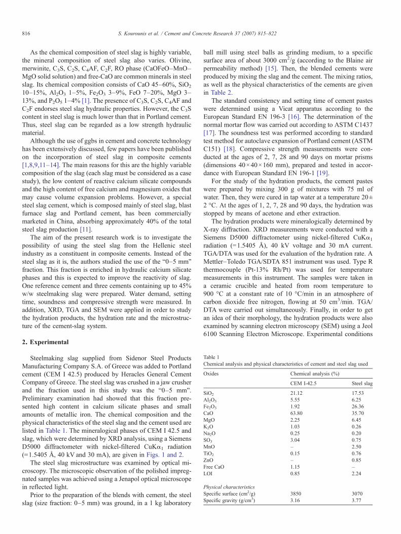
Table 1Chemical analysis and physical characteristics of cement and steel slag used
Oxides Chemical analysis (%)
CEM I-42.5 Steel slag
SiO2 21.12 17.53Al2O3 5.55 6.25Fe2O3 1.92 26.36CaO 63.80 35.70MgO 2.25 6.45K2O 1.03 0.26Na2O 0.25 0.20SO3 3.04 0.75MnO – 2.50TiO2 0.15 0.76ZnO – 0.85Free CaO 1.15 –LOI 0.85 2.24
Physical characteristicsSpecific surface (cm2/g) 3850 3070Specific gravity (g/cm3) 3.16 3.77
816 S. Kourounis et al. / Cement and Concrete Research 37 (2007) 815–822
As the chemical composition of steel slag is highly variable,the mineral composition of steel slag also varies. Olivine,merwinite, C3S, C2S, C4AF, C2F, RO phase (CaOFeO–MnO–MgO solid solution) and free-CaO are common minerals in steelslag. Its chemical composition consists of CaO 45–60%, SiO2
10–15%, Al2O3 1–5%, Fe2O3 3–9%, FeO 7–20%, MgO 3–13%, and P2O5 1–4% [1]. The presence of C3S, C2S, C4AF andC2F endorses steel slag hydraulic properties. However, the C3Scontent in steel slag is much lower than that in Portland cement.Thus, steel slag can be regarded as a low strength hydraulicmaterial.
Although the use of ggbs in cement and concrete technologyhas been extensively discussed, few papers have been publishedon the incorporation of steel slag in composite cements[1,8,9,11–14]. The main reasons for this are the highly variablecomposition of the slag (each slag must be considered as a casestudy), the low content of reactive calcium silicate compoundsand the high content of free calcium and magnesium oxides thatmay cause volume expansion problems. However, a specialsteel slag cement, which is composed mainly of steel slag, blastfurnace slag and Portland cement, has been commerciallymarketed in China, absorbing approximately 40% of the totalsteel slag production [11].
The aim of the present research work is to investigate thepossibility of using the steel slag from the Hellenic steelindustry as a constituent in composite cements. Instead of thesteel slag as it is, the authors studied the use of the “0–5 mm”fraction. This fraction is enriched in hydraulic calcium silicatephases and this is expected to improve the reactivity of slag.One reference cement and three cements containing up to 45%w/w steelmaking slag were prepared. Water demand, settingtime, soundness and compressive strength were measured. Inaddition, XRD, TGA and SEM were applied in order to studythe hydration products, the hydration rate and the microstruc-ture of the cement-slag system.
2. Experimental
Steelmaking slag supplied from Sidenor Steel ProductsManufacturing Company S.A. of Greece was added to Portlandcement (CEM I 42.5) produced by Heracles General CementCompany of Greece. The steel slag was crushed in a jaw crusherand the fraction used in this study was the “0–5 mm”.Preliminary examination had showed that this fraction pre-sented high content in calcium silicate phases and smallamounts of metallic iron. The chemical composition and thephysical characteristics of the steel slag and the cement used arelisted in Table 1. The mineralogical phases of CEM I 42.5 andslag, which were determined by XRD analysis, using a SiemensD5000 diffractometer with nickel-filtered CuKα1 radiation(=1.5405 Å, 40 kV and 30 mA), are given in Figs. 1 and 2.
The steel slag microstructure was examined by optical mi-croscopy. The microscopic observation of the polished impreg-nated samples was achieved using a Jenapol optical microscopein reflected light.
Prior to the preparation of the blends with cement, the steelslag (size fraction: 0–5 mm) was ground, in a 1 kg laboratory
ball mill using steel balls as grinding medium, to a specificsurface area of about 3000 cm2/g (according to the Blaine airpermeability method) [15]. Then, the blended cements wereproduced by mixing the slag and the cement. The mixing ratios,as well as the physical characteristics of the cements are givenin Table 2.
The standard consistency and setting time of cement pasteswere determined using a Vicat apparatus according to theEuropean Standard EN 196-3 [16]. The determination of thenormal mortar flow was carried out according to ASTM C1437[17]. The soundness test was performed according to standardtest method for autoclave expansion of Portland cement (ASTMC151) [18]. Compressive strength measurements were con-ducted at the ages of 2, 7, 28 and 90 days on mortar prisms(dimensions 40×40×160 mm), prepared and tested in accor-dance with European Standard EN 196-1 [19].
For the study of the hydration products, the cement pasteswere prepared by mixing 300 g of mixtures with 75 ml ofwater. Then, they were cured in tap water at a temperature 20±2 °C. At the ages of 1, 2, 7, 28 and 90 days, the hydration wasstopped by means of acetone and ether extraction.
The hydration products were mineralogically determined byX-ray diffraction. XRD measurements were conducted with aSiemens D5000 diffractometer using nickel-filtered CuKα1
radiation (=1.5405 Å), 40 kV voltage and 30 mA current.TGA/DTAwas used for the evaluation of the hydration rate. AMettler–Toledo TGA/SDTA 851 instrument was used. Type Rthermocouple (Pt-13% Rh/Pt) was used for temperaturemeasurements in this instrument. The samples were taken ina ceramic crucible and heated from room temperature to900 °C at a constant rate of 10 °C/min in an atmosphere ofcarbon dioxide free nitrogen, flowing at 50 cm3/min. TGA/DTA were carried out simultaneously. Finally, in order to getan idea of their morphology, the hydration products were alsoexamined by scanning electron microscopy (SEM) using a Jeol6100 Scanning Electron Microscope. Experimental conditions
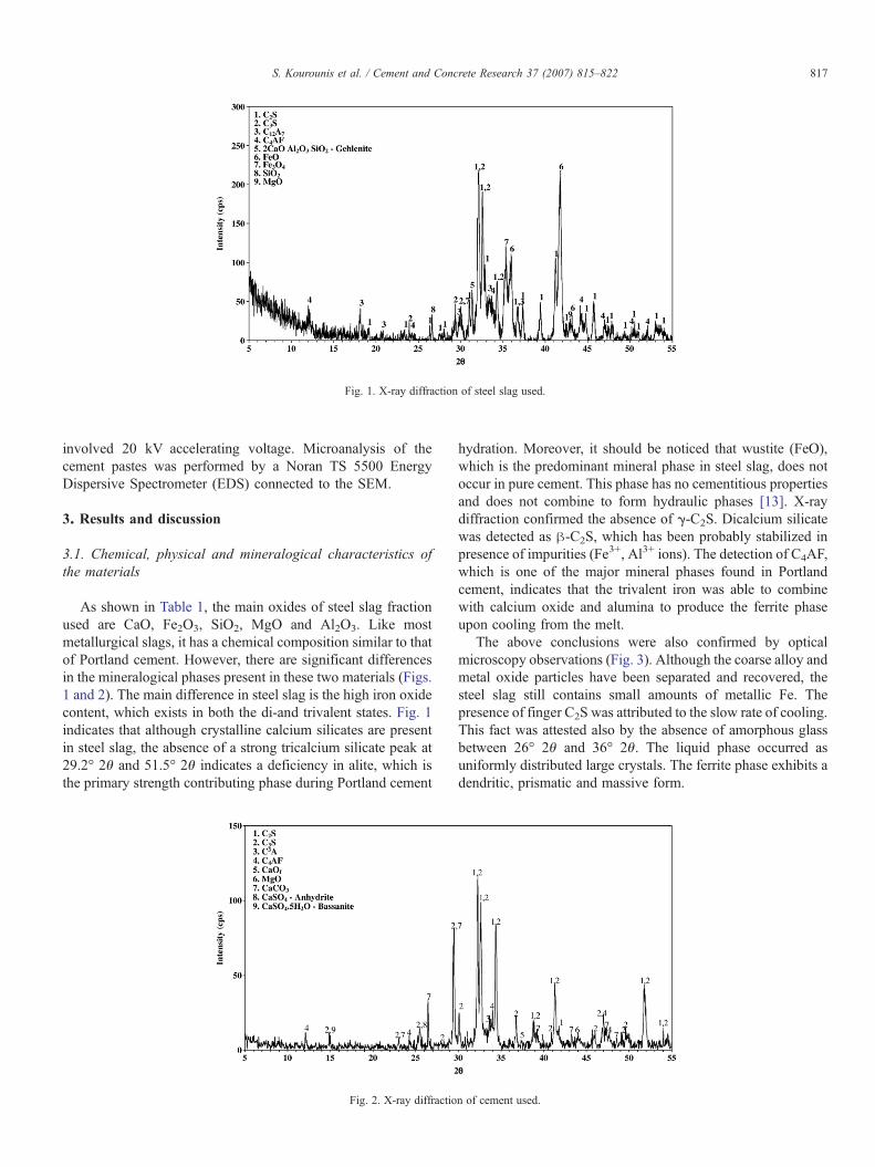
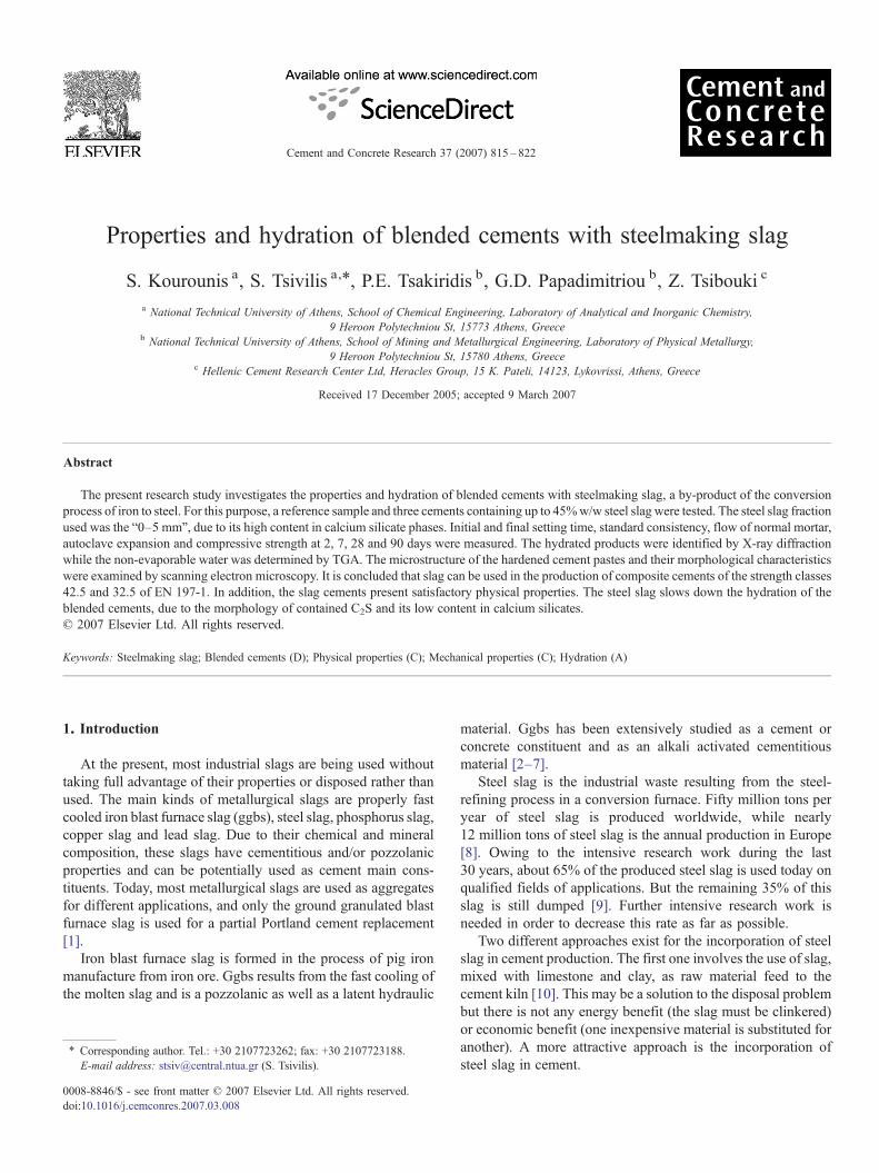
Fig. 1. X-ray diffraction of steel slag used.
817S. Kourounis et al. / Cement and Concrete Research 37 (2007) 815–822
involved 20 kV accelerating voltage. Microanalysis of thecement pastes was performed by a Noran TS 5500 EnergyDispersive Spectrometer (EDS) connected to the SEM.
3. Results and discussion
3.1. Chemical, physical and mineralogical characteristics ofthe materials
As shown in Table 1, the main oxides of steel slag fractionused are CaO, Fe2O3, SiO2, MgO and Al2O3. Like mostmetallurgical slags, it has a chemical composition similar to thatof Portland cement. However, there are significant differencesin the mineralogical phases present in these two materials (Figs.1 and 2). The main difference in steel slag is the high iron oxidecontent, which exists in both the di-and trivalent states. Fig. 1indicates that although crystalline calcium silicates are presentin steel slag, the absence of a strong tricalcium silicate peak at29.2° 2θ and 51.5° 2θ indicates a deficiency in alite, which isthe primary strength contributing phase during Portland cement
Fig. 2. X-ray diffractio
hydration. Moreover, it should be noticed that wustite (FeO),which is the predominant mineral phase in steel slag, does notoccur in pure cement. This phase has no cementitious propertiesand does not combine to form hydraulic phases [13]. X-raydiffraction confirmed the absence of γ-C2S. Dicalcium silicatewas detected as β-C2S, which has been probably stabilized inpresence of impurities (Fe3+, Al3+ ions). The detection of C4AF,which is one of the major mineral phases found in Portlandcement, indicates that the trivalent iron was able to combinewith calcium oxide and alumina to produce the ferrite phaseupon cooling from the melt.
The above conclusions were also confirmed by opticalmicroscopy observations (Fig. 3). Although the coarse alloy andmetal oxide particles have been separated and recovered, thesteel slag still contains small amounts of metallic Fe. Thepresence of finger C2S was attributed to the slow rate of cooling.This fact was attested also by the absence of amorphous glassbetween 26° 2θ and 36° 2θ. The liquid phase occurred asuniformly distributed large crystals. The ferrite phase exhibits adendritic, prismatic and massive form.
n of cement used.
Table 3Physical properties of tested cements
Sample Steel slag(% w/w)
Water demand(% w/w)
Setting time(min)
Autoclaveexpansion(%)
Flowofnormalmortar(%)
Initial Final
C1 – 27.0 155 185 −0.04 103.0C2 15 26.0 170 210 −0.02 108.5C3 30 25.0 210 240 −0.20 111.5C4 45 23.5 220 260 0.33 113.5
Table 2Composition and characteristics of tested cements
Code CEM I 42.5(w/w %)
Steel slag(w/w %)
Specific surfacearea (cm2/g)
Specific gravity(g/cm3)
C1 100 0 3850 3.16C2 85 15 3730 3.24C3 70 30 3620 3.32C4 55 45 3500 3.41
818 S. Kourounis et al. / Cement and Concrete Research 37 (2007) 815–822
3.2. Physical and mechanical properties of blended cements
Table 3 presents the cement water demand, the setting timeand the normal mortar flow of the tested samples. The “waterdemand” is generally considered to be the quantity of waterrequired for the preparation of a cement paste with standardconsistency, as specified in EN 196-3. The slag containingcements demand less water than the reference pure cement. Thewater demand is less, the higher the slag content of the cement.The decreased water demand is attributed to the delayedhydration of the slag, due to its mineralogical composition. Theflow tests confirm the above results and show that the slagaddition improves the mortar workability. The replacement ofcement with slag, which is less reactive than pure cement,reduces the amount of ettringite formed during the earlyhydration thus resulting to higher workability of the mortar [3].
The blended cements showed longer setting times than thepure cement. This is expected as the increase of steel slagcontent reduces the cement content in the mix (cement dilutioneffect). As a result, hydration process slows down causingsetting time to increase. The longer setting time of slag cementshas also been reported by other authors and has been associatedwith the low Al2O3 content and/or high MgO and MnO2 contentin the slag. It must be noted that this particular slag has lowerMgO and MnO2 content and higher Al2O3 content incomparison with others mentioned in the literature and thisseems to be the reason for the less pronounced setting delay[8,20]. In any case, the low hydration rate is an advantage forcertain applications, since it means low rate of heat evolution, afact that is of great importance in mass concrete constructions.
Fig. 3. Microstructure of steel slag used (a: finger C2S and skeletal C3S due to slow(×200)).
The results of the autoclave expansion are presented inTable 3. In the case of cements containing 15% and 30% slag,the changes in length of the test specimens are high enough, butthey satisfy the standard requirements of ASTM C 151 (maxautoclave expansion: 0.8%).
Fig. 4 shows the compressive strength development of slagcements in relation to the cement replacement level. It isobserved that slag cements develop lower strength, at all ages,compared to reference cement. The strength decrease is higher,the higher the slag content. The results in Fig. 4 confirm thatcements containing 15% or 30% slag satisfy the requirements ofthe strength class 42.5 of EN 197-1, while the cementcontaining 45% slag satisfies the requirements of the strengthclass 32.5 of EN 197-1.
Fig. 5 presents the relative strength of tested cements inrelation to curing age and replacement level. Relative strength isthe ratio of the strength of the slag cement to the strength of thereference cement at each particular curing time. The rate ofstrength development of reference cement depends mainly onits hydration rate, while in cement-slag systems it also dependson the hydration and the latent hydraulic reactions of slag.Therefore, the relative strength-time plots provide an insightinto the rates of reaction in the blended system relative to thepure cement. Fig. 5 shows that at 7 days the slag cementspresent a compressive strength that equals the 82%, 63% and46% of the reference cement strength for 15%, 30% and 45%slag content respectively. At 90 days the slag cements present acompressive strength that equals the 92%, 81% and 59% of the
cooling (×500), b: entrapped metallic Fe and anhedral C3S with decomposition
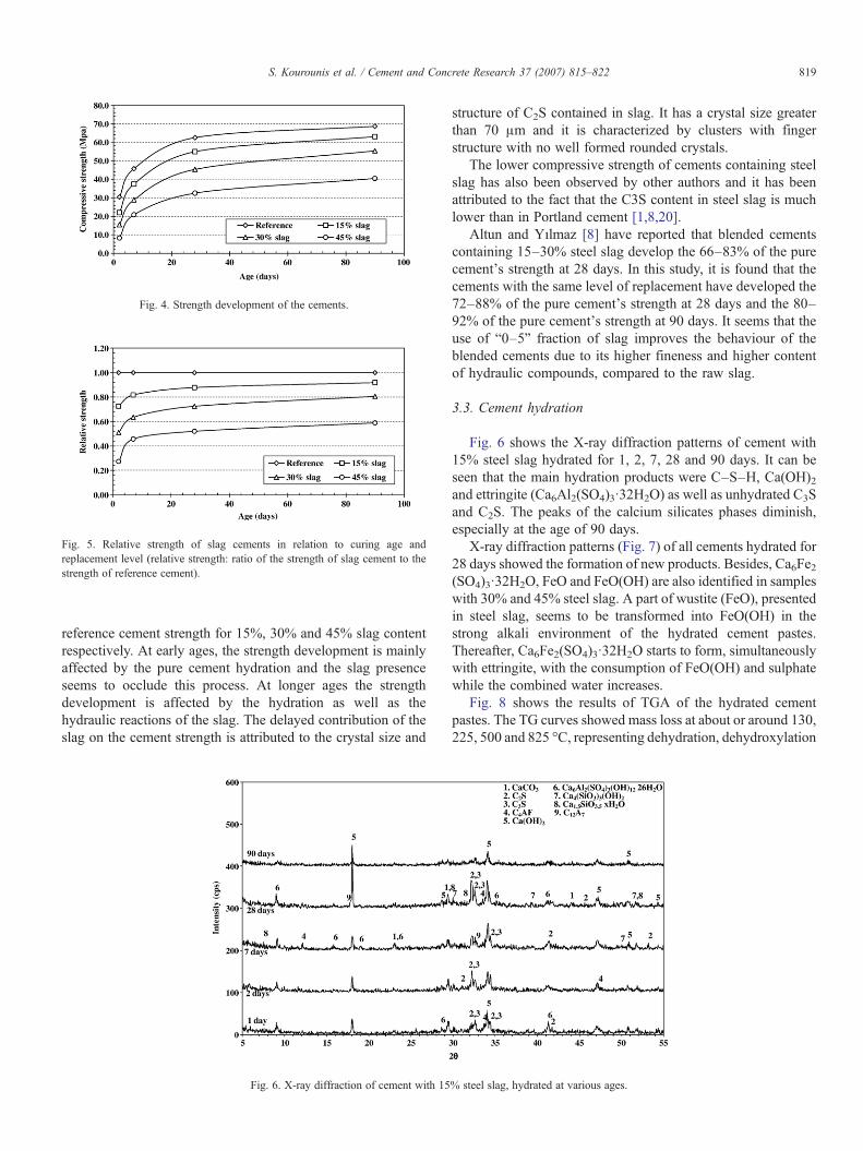
Fig. 5. Relative strength of slag cements in relation to curing age andreplacement level (relative strength: ratio of the strength of slag cement to thestrength of reference cement).
Fig. 4. Strength development of the cements.
819S. Kourounis et al. / Cement and Concrete Research 37 (2007) 815–822
reference cement strength for 15%, 30% and 45% slag contentrespectively. At early ages, the strength development is mainlyaffected by the pure cement hydration and the slag presenceseems to occlude this process. At longer ages the strengthdevelopment is affected by the hydration as well as thehydraulic reactions of the slag. The delayed contribution of theslag on the cement strength is attributed to the crystal size and
Fig. 6. X-ray diffraction of cement with 15
structure of C2S contained in slag. It has a crystal size greaterthan 70 μm and it is characterized by clusters with fingerstructure with no well formed rounded crystals.
The lower compressive strength of cements containing steelslag has also been observed by other authors and it has beenattributed to the fact that the C3S content in steel slag is muchlower than in Portland cement [1,8,20].
Altun and Yılmaz [8] have reported that blended cementscontaining 15–30% steel slag develop the 66–83% of the purecement's strength at 28 days. In this study, it is found that thecements with the same level of replacement have developed the72–88% of the pure cement's strength at 28 days and the 80–92% of the pure cement's strength at 90 days. It seems that theuse of “0–5” fraction of slag improves the behaviour of theblended cements due to its higher fineness and higher contentof hydraulic compounds, compared to the raw slag.
3.3. Cement hydration
Fig. 6 shows the X-ray diffraction patterns of cement with15% steel slag hydrated for 1, 2, 7, 28 and 90 days. It can beseen that the main hydration products were C–S–H, Ca(OH)2and ettringite (Ca6Al2(SO4)3·32H2O) as well as unhydrated C3Sand C2S. The peaks of the calcium silicates phases diminish,especially at the age of 90 days.
X-ray diffraction patterns (Fig. 7) of all cements hydrated for28 days showed the formation of new products. Besides, Ca6Fe2(SO4)3·32H2O, FeO and FeO(OH) are also identified in sampleswith 30% and 45% steel slag. A part of wustite (FeO), presentedin steel slag, seems to be transformed into FeO(OH) in thestrong alkali environment of the hydrated cement pastes.Thereafter, Ca6Fe2(SO4)3·32H2O starts to form, simultaneouslywith ettringite, with the consumption of FeO(OH) and sulphatewhile the combined water increases.
Fig. 8 shows the results of TGA of the hydrated cementpastes. The TG curves showed mass loss at about or around 130,225, 500 and 825 °C, representing dehydration, dehydroxylation
% steel slag, hydrated at various ages.
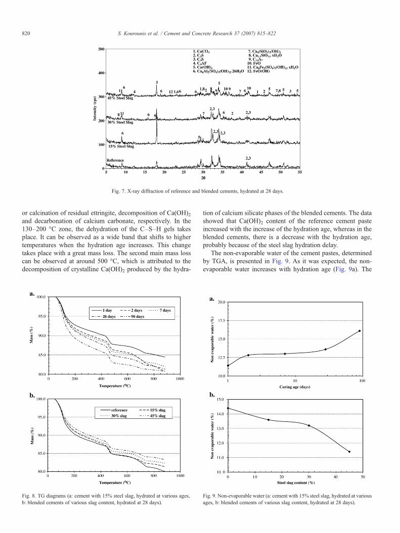
Fig. 7. X-ray diffraction of reference and blended cements, hydrated at 28 days.
820 S. Kourounis et al. / Cement and Concrete Research 37 (2007) 815–822
or calcination of residual ettringite, decomposition of Ca(OH)2and decarbonation of calcium carbonate, respectively. In the130–200 °C zone, the dehydration of the C–S–H gels takesplace. It can be observed as a wide band that shifts to highertemperatures when the hydration age increases. This changetakes place with a great mass loss. The second main mass losscan be observed at around 500 °C, which is attributed to thedecomposition of crystalline Ca(OH)2 produced by the hydra-
Fig. 8. TG diagrams (a: cement with 15% steel slag, hydrated at various ages,b: blended cements of various slag content, hydrated at 28 days).
tion of calcium silicate phases of the blended cements. The datashowed that Ca(OH)2 content of the reference cement pasteincreased with the increase of the hydration age, whereas in theblended cements, there is a decrease with the hydration age,probably because of the steel slag hydration delay.
The non-evaporable water of the cement pastes, determinedby TGA, is presented in Fig. 9. As it was expected, the non-evaporable water increases with hydration age (Fig. 9a). The
Fig. 9. Non-evaporable water (a: cement with 15% steel slag, hydrated at variousages, b: blended cements of various slag content, hydrated at 28 days).
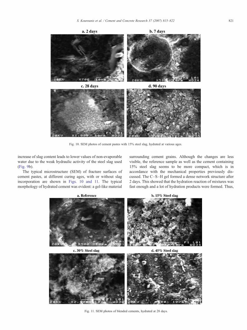
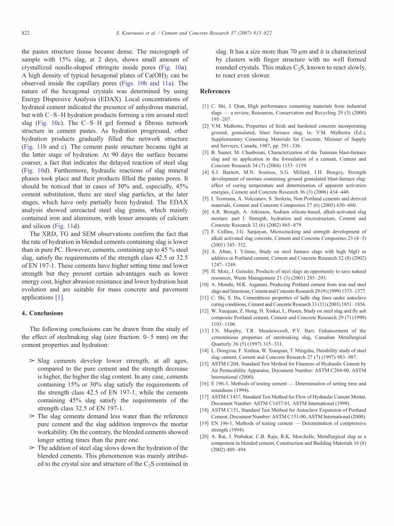
Fig. 10. SEM photos of cement pastes with 15% steel slag, hydrated at various ages.
821S. Kourounis et al. / Cement and Concrete Research 37 (2007) 815–822
increase of slag content leads to lower values of non-evaporablewater due to the weak hydraulic activity of the steel slag used(Fig. 9b).
The typical microstructure (SEM) of fracture surfaces ofcement pastes, at different curing ages, with or without slagincorporation are shown in Figs. 10 and 11. The typicalmorphology of hydrated cement was evident: a gel-like material
Fig. 11. SEM photos of blended c
surrounding cement grains. Although the changes are lessvisible, the reference sample as well as the cement containing15% steel slag seems to be more compact, which is inaccordance with the mechanical properties previously dis-cussed. The C–S–H gel formed a dense network structure after2 days. This showed that the hydration reaction of mixtures wasfast enough and a lot of hydration products were formed. Thus,
ements, hydrated at 28 days.
822 S. Kourounis et al. / Cement and Concrete Research 37 (2007) 815–822
the pastes structure tissue became dense. The micrograph ofsample with 15% slag, at 2 days, shows small amount ofcrystallized needle-shaped ettringite inside pores (Fig. 10a).A high density of typical hexagonal plates of Ca(OH)2 can beobserved inside the capillary pores (Figs. 10b and 11a). Thenature of the hexagonal crystals was determined by usingEnergy Dispersive Analysis (EDAX). Local concentrations ofhydrated cement indicated the presence of anhydrous material,but with C–S–H hydration products forming a rim around steelslag (Fig. 10c). The C–S–H gel formed a fibrous networkstructure in cement pastes. As hydration progressed, otherhydration products gradually filled the network structure(Fig. 11b and c). The cement paste structure became tight atthe latter stage of hydration. At 90 days the surface becamecoarser, a fact that indicates the delayed reaction of steel slag(Fig. 10d). Furthermore, hydraulic reactions of slag mineralphases took place and their products filled the pastes pores. Itshould be noticed that in cases of 30% and, especially, 45%cement substitution, there are steel slag particles, at the laterstages, which have only partially been hydrated. The EDAXanalysis showed unreacted steel slag grains, which mainlycontained iron and aluminum, with lesser amounts of calciumand silicon (Fig. 11d).
The XRD, TG and SEM observations confirm the fact thatthe rate of hydration in blended cements containing slag is lowerthan in pure PC. However, cements, containing up to 45 % steelslag, satisfy the requirements of the strength class 42.5 or 32.5of EN 197-1. These cements have higher setting time and lowerstrength but they present certain advantages such as lowerenergy cost, higher abrasion resistance and lower hydration heatevolution and are suitable for mass concrete and pavementapplications [1].
4. Conclusions
The following conclusions can be drawn from the study ofthe effect of steelmaking slag (size fraction: 0–5 mm) on thecement properties and hydration:
➢ Slag cements develop lower strength, at all ages,compared to the pure cement and the strength decreaseis higher, the higher the slag content. In any case, cementscontaining 15% or 30% slag satisfy the requirements ofthe strength class 42.5 of EN 197-1, while the cementscontaining 45% slag satisfy the requirements of thestrength class 32.5 of EN 197-1.
➢ The slag cements demand less water than the referencepure cement and the slag addition improves the mortarworkability. On the contrary, the blended cements showedlonger setting times than the pure one.
➢ The addition of steel slag slows down the hydration of theblended cements. This phenomenon was mainly attribut-ed to the crystal size and structure of the C2S contained in
slag. It has a size more than 70 μm and it is characterizedby clusters with finger structure with no well formedrounded crystals. This makes C2S, known to react slowly,to react even slower.
References
[1] C. Shi, J. Qian, High performance cementing materials from industrialslags — a review, Resources, Conservation and Recycling 29 (3) (2000)195–207.
[2] V.M. Malhotra, Properties of fresh and hardened concrete incorporatingground, granulated, blast furnace slag, in: V.M. Malhotra (Ed.),Supplementary Cementing Materials for Concrete, Minister of Supplyand Services, Canada, 1987, pp. 291–336.
[3] B. Samet, M. Chaabouni, Characterization of the Tunisian blast-furnaceslag and its application in the formulation of a cement, Cement andConcrete Research 34 (7) (2004) 1153–1159.
[4] S.J. Barnett, M.N. Soutsos, S.G. Millard, J.H. Bungey, Strengthdevelopment of mortars containing ground granulated blast-furnace slag:effect of curing temperature and determination of apparent activationenergies, Cement and Concrete Research 36 (3) (2006) 434–440.
[5] I. Teoreanu, A. Volceanov, S. Stoleriu, Non Portland cements and derivedmaterials, Cement and Concrete Composites 27 (6) (2005) 650–660.
[6] A.R. Brough, A. Atkinson, Sodium silicate-based, alkali-activated slagmortars: part I. Strength, hydration and microstructure, Cement andConcrete Research 32 (6) (2002) 865–879.
[7] F. Collins, J.G. Sanjayan, Microcracking and strength development ofalkali activated slag concrete, Cement and Concrete Composites 23 (4–5)(2001) 345–352.
[8] A. Altun, I. Yılmaz, Study on steel furnace slags with high MgO asadditive in Portland cement, Cement and Concrete Research 32 (8) (2002)1247–1249.
[9] H. Motz, J. Geiseler, Products of steel slags an opportunity to save naturalresources, Waste Management 21 (3) (2001) 285–293.
[10] A. Monshi, M.K. Asgarani, Producing Portland cement from iron and steelslags and limestone, Cement andConcreteResearch 29 (9) (1999) 1373–1377.
[11] C. Shi, S. Hu, Cementitious properties of ladle slag fines under autoclavecuring conditions, Cement andConcrete Research 33 (11) (2003) 1851–1856.
[12] W. Xuequan, Z. Hong, H. Xinkai, L. Husen, Study on steel slag and fly ashcomposite Portland cement, Cement and Concrete Research 29 (7) (1999)1103–1106.
[13] J.N. Murphy, T.R. Meadowcroft, P.V. Barr, Enhancement of thecementitious properties of steelmaking slag, Canadian MetallurgicalQuarterly 36 (5) (1997) 315–331.
[14] L. Dongxue, F. Xinhua, W. Xuequan, T. Mingshu, Durability study of steelslag cement, Cement and Concrete Research 27 (7) (1997) 983–987.
[15] ASTM C204, Standard Test Method for Fineness of Hydraulic Cement byAir Permeability Apparatus, Document Number: ASTM C204-00, ASTMInternational (2000).
[16] E 196-3, Methods of testing cement — Determination of setting time andsoundness (1994).
[17] ASTMC1437, Standard Test Method for Flow of Hydraulic Cement Mortar,Document Number: ASTM C1437-01, ASTM International (1999).
[18] ASTM C151, Standard Test Method for Autoclave Expansion of PortlandCement, Document Number: ASTMC151-00, ASTM International (2000).
[19] EN 196-1, Methods of testing cement — Determination of compressivestrength (1994).
[20] A. Rai, J. Prabakar, C.B. Raju, R.K. Morchalle, Metallurgical slag as acomponent in blended cement, Construction and Building Materials 16 (8)(2002) 489–494.