professional/contractor salt spreader · c. slide through the other side of the hopper frame. ......
TRANSCRIPT
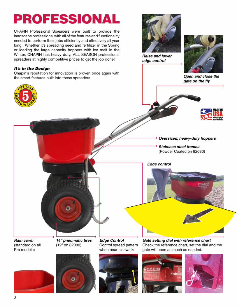


PROFESSIONAL/CONTRACTOR SALT SPREADER Assembly / Operation Instructions / Parts
CHAPIN INTERNATIONAL, INC. P.O. BOX 549 700 ELLICOTT ST. BATAVIA, NY 14021-0549 www.chapinmfg.com 800-950-4458
Please call 800-950-4458 if you are missing any parts, having trouble assembling, or have any questions regarding the safe operation of this product.
DO NOT RETURN TO THE STORE
MODEL 82108N/82088N
Carefully Read These Instructions Before Use
IMPROPER USE OR FAILURE TO FOLLOW INSTRUCTIONS CAN RESULT IN PRODUCT FAILURE OR INJURIES. FOR SAFE USE OF THIS PRODUCT YOU MUST READ AND FOLLOW ALL INSTRUCTIONS BEFORE USING.
- Do not allow anyone to operate the broadcast spreader without proper instructions- Do not permit children to operate the broadcast spreader- Wear protective eyewear and gloves when handling and applying lawn and garden chemicals- Read the chemical label instructions and warnings for handling and applying the chemicals you plan to spread – application settings provided are only a guideline
WARNING
Model 82108N100 lb. Spreader
013524 R0714
Model 82088N80 lb. Spreader
ASSEMBLY INSTRUCTIONS
CHAPIN INTERNATIONAL, INC. P.O. BOX 549 700 ELLICOTT ST. BATAVIA, NY 14021-0549 www.chapinmfg.com 800-950-4458
Suggested Tools:Wrench and/or Ratchet Set1.5mm Allen WrenchPliersProtective Eyewear
Approximate assembly time is 20-45 minutes
NOTE: Depending on model, this package may contain additional hardware not needed for assembly.
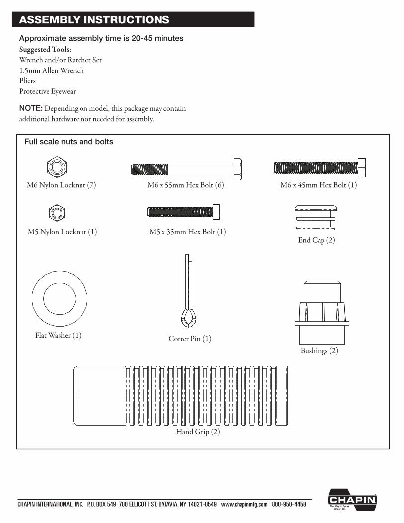
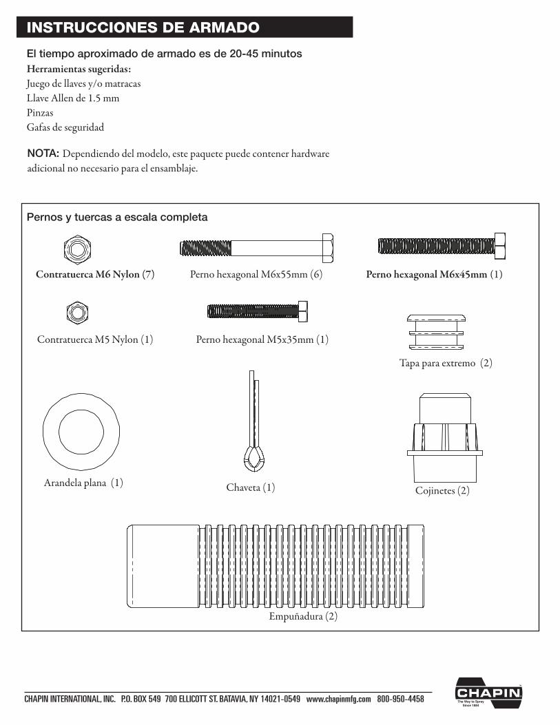
Full scale nuts and bolts
M5 Nylon Locknut (1)
M6 Nylon Locknut (7) M6 x 55mm Hex Bolt (6) M6 x 45mm Hex Bolt (1)
M5 x 35mm Hex Bolt (1)
Flat Washer (1) Cotter Pin (1)
End Cap (2)
Hand Grip (2)
Bushings (2)
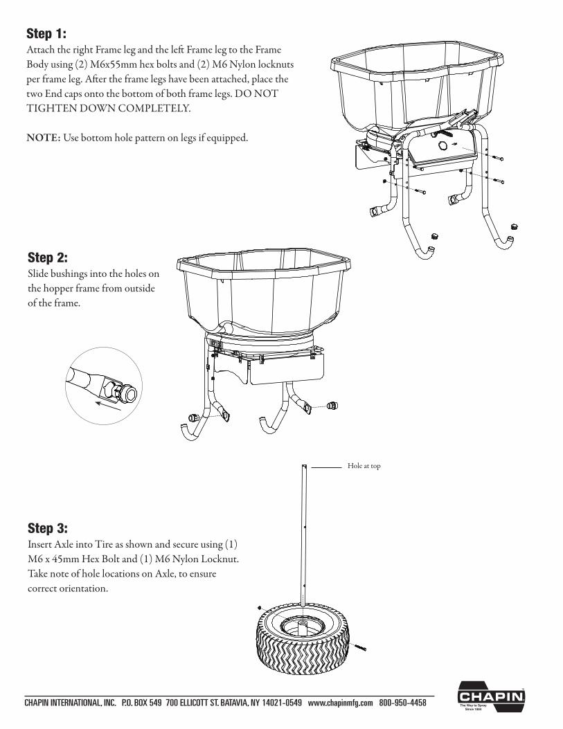
Step 1:Attach the right Frame leg and the left Frame leg to the Frame Body using (2) M6x55mm hex bolts and (2) M6 Nylon locknuts per frame leg. After the frame legs have been attached, place the two End caps onto the bottom of both frame legs. DO NOT TIGHTEN DOWN COMPLETELY.
NOTE: Use bottom hole pattern on legs if equipped.
CHAPIN INTERNATIONAL, INC. P.O. BOX 549 700 ELLICOTT ST. BATAVIA, NY 14021-0549 www.chapinmfg.com 800-950-4458
Step 2:Slide bushings into the holes on the hopper frame from outside of the frame.
Step 3:Insert Axle into Tire as shown and secure using (1) M6 x 45mm Hex Bolt and (1) M6 Nylon Locknut. Take note of hole locations on Axle, to ensure correct orientation.
Hole at top
CHAPIN INTERNATIONAL, INC. P.O. BOX 549 700 ELLICOTT ST. BATAVIA, NY 14021-0549 www.chapinmfg.com 800-950-4458
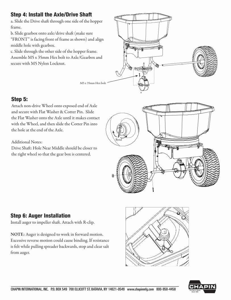
Step 4: Install the Axle/Drive Shafta. Slide the Drive shaft through one side of the hopper frame.b. Slide gearbox onto axle/drive shaft (make sure “FRONT” is facing front of frame as shown) and align middle hole with gearbox.c. Slide through the other side of the hopper frame. Assemble M5 x 35mm Hex bolt to Axle/Gearbox and secure with M5 Nylon Locknut.
Step 5:Attach non-drive Wheel onto exposed end of Axle and secure with Flat Washer & Cotter Pin. Slide the Flat Washer onto the Axle until it makes contact with the Wheel, and then slide the Cotter Pin into the hole at the end of the Axle. Additional Notes:Drive Shaft: Hole Near Middle should be closer to the right wheel so that the gear box is centered.
Bend
M5 x 35mm Hex bolt
Step 6: Auger InstallationInstall auger to impeller shaft. Attach with R-clip.
NOTE: Auger is designed to work in forward motion. Excessive reverse motion could cause binding. If resistance is felt while pulling spreader backwards, stop and clear salt from auger.
CHAPIN INTERNATIONAL, INC. P.O. BOX 549 700 ELLICOTT ST. BATAVIA, NY 14021-0549 www.chapinmfg.com 800-950-4458
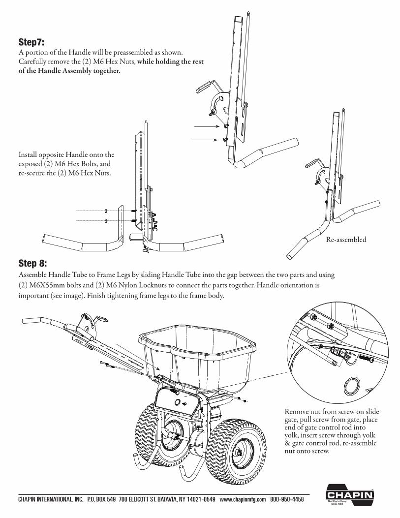
Step7: A portion of the Handle will be preassembled as shown. Carefully remove the (2) M6 Hex Nuts, while holding the rest of the Handle Assembly together.
Install opposite Handle onto the exposed (2) M6 Hex Bolts, and re-secure the (2) M6 Hex Nuts.
Re-assembled
Step 8:Assemble Handle Tube to Frame Legs by sliding Handle Tube into the gap between the two parts and using (2) M6X55mm bolts and (2) M6 Nylon Locknuts to connect the parts together. Handle orientation is important (see image). Finish tightening frame legs to the frame body.
Remove nut from screw on slide gate, pull screw from gate, place end of gate control rod into yolk, insert screw through yolk & gate control rod, re-assemble nut onto screw.
CHAPIN INTERNATIONAL, INC. P.O. BOX 549 700 ELLICOTT ST. BATAVIA, NY 14021-0549 www.chapinmfg.com 800-950-4458
• Whenfinishedspreadingemptyhopperofanyremainingmaterial.• Thoroughlywashspreaderandallowtodrybeforestoring.• Gearsarepermanentlylubricatedatthefactory.DONOTopenthegearboxatanytimeasdebrismayenter and interfere with functionality.• Whenusingrocksaltandice-meltproductsbesuretoemptythehopperuponcompletionofspreadingeach timeyouuseit.Thesematerialsmayreconstitutebackintoasolidblockovernightwithhumidity.Theycanalso damage metal parts if exposed for extended periods of time.
STORAGE AND MAINTENANCE
•Besuregatecontrolisintheclosedposition.•Determineappropriatesettingformaterialbeingusedbyreadingthesuggestedsettingonthematerial’sbag.•Tobeginspreading,startwalking(about3mphpace)andpullthegatecontroldowntoopengate.•Tostopspreadingsimplypushgatecontrolupandthegatewillclose.
GENERAL OPERATING INSTRUCTIONS
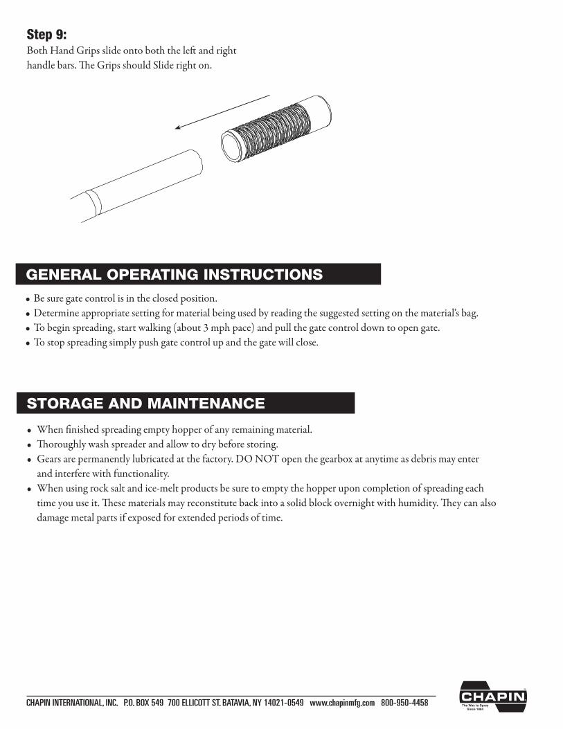
Step 9:Both Hand Grips slide onto both the left and right handlebars.TheGripsshouldSliderighton.
CHAPIN INTERNATIONAL, INC. P.O. BOX 549 700 ELLICOTT ST. BATAVIA, NY 14021-0549 www.chapinmfg.com 800-950-4458
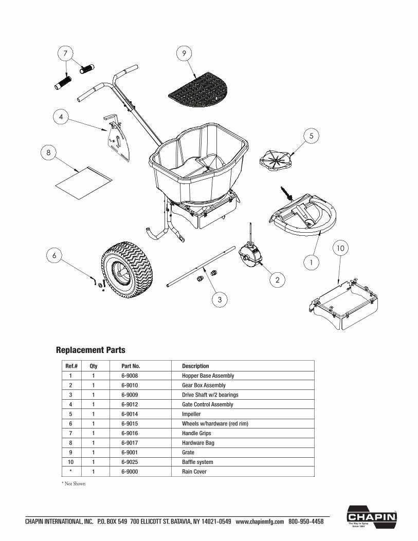
Replacement Parts
Ref.# Qty Part No. Description
1 1 6-9008 Hopper Base Assembly
2 1 6-9010 Gear Box Assembly
3 1 6-9009 Drive Shaft w/2 bearings
4 1 6-9012 Gate Control Assembly
5 1 6-9014 Impeller
6 1 6-9015 Wheels w/hardware (red rim)
7 1 6-9016 Handle Grips
8 1 6-9017 Hardware Bag
9 1 6-9001 Grate
10 1 6-9025 Baffle system
* 1 6-9000 Rain Cover
* Not Shown
1
2
3
4
5
6
7
8
9
10

013524 R0714
Esparcidor profesional de sal Armado / Operación Instrucciones / Partes
CHAPIN INTERNATIONAL, INC BOX 549 700 ELLICOTT ST. BATAVIA, NY 14021-0549 www.chapinmfg.com 800-950-4458
Por favor llame al 800-950-4458 si le falta alguna parte, si tiene problemas con el armado o si tiene alguna pregunta sobre la operación segura de este producto.
NO DEVUELVA A LA TIENDA
MODEL 82108N/82088N
Lea estas instrucciones atentamente antes de utilizarlo
EL USO INAPROPIADO O NO SEGUIR LAS INSTRUCCIONES PUEDE RESULTAR EN FALLAS DEL PRODUCTO O LESIONES. PARA USAR ESTE PRODUCTO DE MANERA SEGURA DEBE LEER Y SEGUIR TODAS LAS INSTRUCCIONES ANTES DE USARLO.
- No permita que nadie opere el esparcidor a voleo sin las instrucciones apropiadas- No permita que niños operen el esparcidor a voleo- Use gafas de seguridad y guantes al manejar y aplicar sustancias químicas a patios y jardines- Lea las instrucciones y advertencias químicas en la etiqueta respecto al manejo y aplicación de las sustancias que
planea esparcir – las configuraciones de aplicación proporcionadas son sólo una guía
ADVERTENCIA
Model 82108N45 kg (100 lb) Esparcidora Model 82088N
36 kg (80 lb) Esparcidora
CHAPIN INTERNATIONAL, INC. P.O. BOX 549 700 ELLICOTT ST. BATAVIA, NY 14021-0549 www.chapinmfg.com 800-950-4458
Pernos y tuercas a escala completa
Contratuerca M5 Nylon (1)
Contratuerca M6 Nylon (7) Perno hexagonal M6x55mm (6) Perno hexagonal M6x45mm (1)
Perno hexagonal M5x35mm (1)
Arandela plana (1) Chaveta (1)
Tapa para extremo (2)
Empuñadura (2)
Cojinetes (2)
INSTRUCCIONES DE ARMADO
Herramientas sugeridas:Juego de llaves y/o matracasLlave Allen de 1.5 mmPinzasGafas de seguridad
El tiempo aproximado de armado es de 20-45 minutos
NOTA: Dependiendo del modelo, este paquete puede contener hardware adicional no necesario para el ensamblaje.
CHAPIN INTERNATIONAL, INC. P.O. BOX 549 700 ELLICOTT ST. BATAVIA, NY 14021-0549 www.chapinmfg.com 800-950-4458
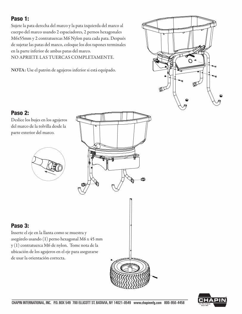
Paso 3:Inserte el eje en la llanta como se muestra y asegúrelo usando (1) perno hexagonal M6 x 45 mm y (1) contratuerca M6 de nylon. Tome nota de la ubicación de los agujeros en el eje para asegurarse de usar la orientación correcta.
Paso 1:Sujete la pata derecha del marco y la pata izquierda del marco al cuerpo del marco usando 2 espaciadores, 2 pernos hexagonales M6x55mm y 2 contratuercas M6 Nylon para cada pata. Después de sujetar las patas del marco, coloque los dos tapones terminales en la parte inferior de ambas patas del marco. NO APRIETE LAS TUERCAS COMPLETAMENTE.
NOTA: Use el patrón de agujeros inferior si está equipado.
Paso 2:Deslice los bujes en los agujeros del marco de la tolvilla desde la parte exterior del marco.
CHAPIN INTERNATIONAL, INC. P.O. BOX 549 700 ELLICOTT ST. BATAVIA, NY 14021-0549 www.chapinmfg.com 800-950-4458
Bend
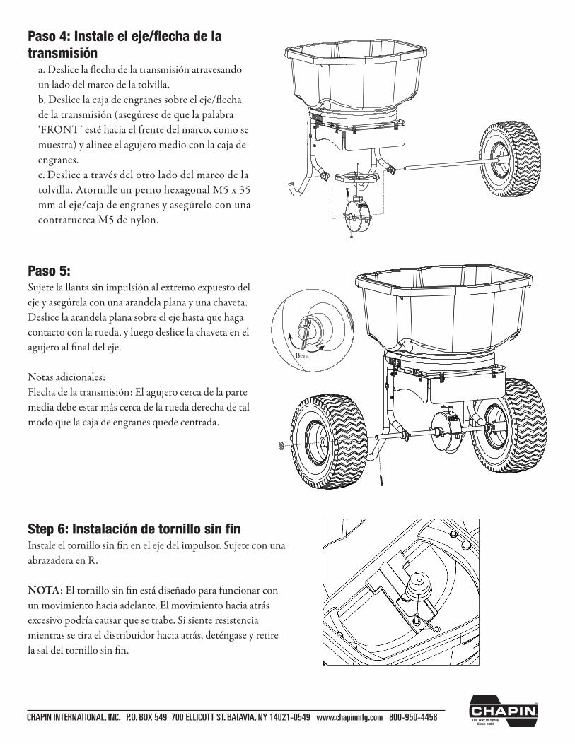
Paso 4: Instale el eje/flecha de la transmisión a. Deslice la flecha de la transmisión atravesando
un lado del marco de la tolvilla. b. Deslice la caja de engranes sobre el eje/flecha
de la transmisión (asegúrese de que la palabra ‘FRONT’estéhaciaelfrentedelmarco,comosemuestra) y alinee el agujero medio con la caja de engranes.
c. Deslice a través del otro lado del marco de la tolvilla. Atornille un perno hexagonal M5 x 35 mm al eje/caja de engranes y asegúrelo con una contratuerca M5 de nylon.
Paso 5:Sujete la llanta sin impulsión al extremo expuesto del eje y asegúrela con una arandela plana y una chaveta. Deslice la arandela plana sobre el eje hasta que haga contacto con la rueda, y luego deslice la chaveta en el agujeroalfinaldeleje.
Notas adicionales:Flecha de la transmisión: El agujero cerca de la parte media debe estar más cerca de la rueda derecha de tal modo que la caja de engranes quede centrada.
Step 6: Instalación de tornillo sin finInstaleeltornillosinfinenelejedelimpulsor.Sujeteconunaabrazadera en R.
NOTA:Eltornillosinfinestádiseñadoparafuncionarconun movimiento hacia adelante. El movimiento hacia atrás excesivo podría causar que se trabe. Si siente resistencia mientras se tira el distribuidor hacia atrás, deténgase y retire lasaldeltornillosinfin.
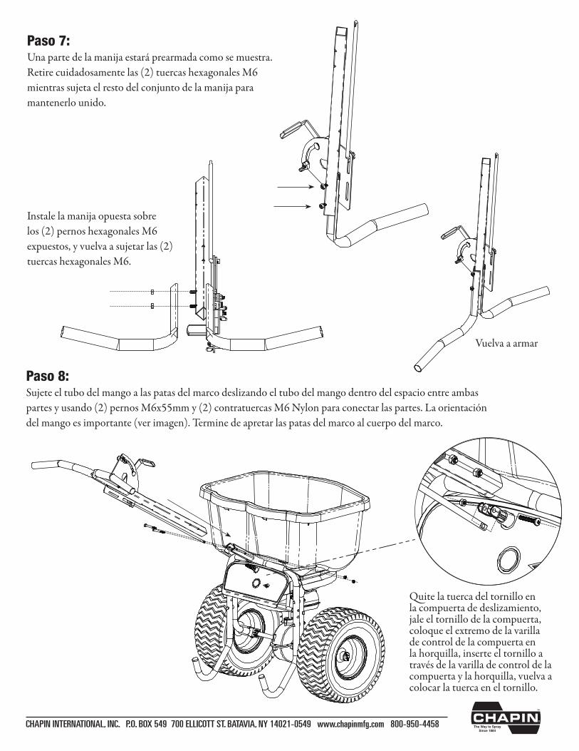
Paso 7: Una parte de la manija estará prearmada como se muestra. Retire cuidadosamente las (2) tuercas hexagonales M6 mientras sujeta el resto del conjunto de la manija para mantenerlo unido.
Instale la manija opuesta sobre los (2) pernos hexagonales M6 expuestos, y vuelva a sujetar las (2) tuercas hexagonales M6.
CHAPIN INTERNATIONAL, INC. P.O. BOX 549 700 ELLICOTT ST. BATAVIA, NY 14021-0549 www.chapinmfg.com 800-950-4458
Paso 8:Sujete el tubo del mango a las patas del marco deslizando el tubo del mango dentro del espacio entre ambas partes y usando (2) pernos M6x55mm y (2) contratuercas M6 Nylon para conectar las partes. La orientación del mango es importante (ver imagen). Termine de apretar las patas del marco al cuerpo del marco.
Quite la tuerca del tornillo en la compuerta de deslizamiento, jale el tornillo de la compuerta, coloque el extremo de la varilla de control de la compuerta en la horquilla, inserte el tornillo a través de la varilla de control de la compuerta y la horquilla, vuelva a colocar la tuerca en el tornillo.
Vuelva a armar
CHAPIN INTERNATIONAL, INC. P.O. BOX 549 700 ELLICOTT ST. BATAVIA, NY 14021-0549 www.chapinmfg.com 800-950-4458
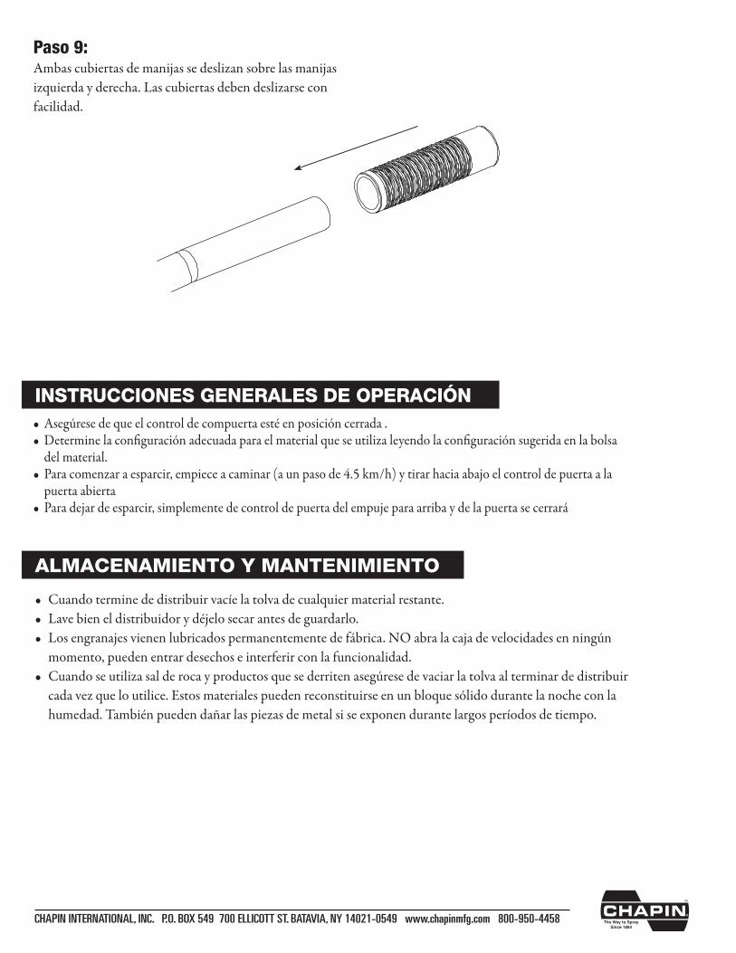
Paso 9:Ambas cubiertas de manijas se deslizan sobre las manijas izquierda y derecha. Las cubiertas deben deslizarse con facilidad.
• Cuandoterminededistribuirvacíelatolvadecualquiermaterialrestante.• Lavebieneldistribuidorydéjelosecarantesdeguardarlo.• Losengranajesvienenlubricadospermanentementedefábrica.NOabralacajadevelocidadesenningún momento, pueden entrar desechos e interferir con la funcionalidad.• Cuandoseutilizasalderocayproductosquesederritenasegúresedevaciarlatolvaalterminardedistribuir cada vez que lo utilice. Estos materiales pueden reconstituirse en un bloque sólido durante la noche con la humedad. También pueden dañar las piezas de metal si se exponen durante largos períodos de tiempo.
ALMACENAMIENTO Y MANTENIMIENTO
• Asegúresedequeelcontroldecompuertaestéenposicióncerrada.• Determinelaconfiguraciónadecuadaparaelmaterialqueseutilizaleyendolaconfiguraciónsugeridaenlabolsa del material.• Paracomenzaraesparcir,empieceacaminar(aunpasode4.5km/h)ytirarhaciaabajoelcontroldepuertaala puerta abierta• Paradejardeesparcir,simplementedecontroldepuertadelempujeparaarribaydelapuertasecerrará
INSTRUCCIONES GENERALES DE OPERACIÓN

CHAPIN INTERNATIONAL, INC. P.O. BOX 549 700 ELLICOTT ST. BATAVIA, NY 14021-0549 www.chapinmfg.com 800-950-4458
* No mostrado
Partes de repuesto
Num. Ref Cant. Num. Parte Descripción
1 1 6-9008 Conjunto de la base de la tolvilla
2 1 6-9010 Conjunto de la caja de engranes
3 1 6-9009 Flecha de transmisión c/2 cojinetes
4 1 6-9012 Conjunto del control de la compuerta
5 1 6-9014 Impulsor
6 1 6-9015 Ruedas C/herrajes (rin rojo)
7 1 6-9016 Cubiertas de manijas
8 1 6-9017 Bolsa de herrajes
9 1 6-9001 Parrilla
10 1 6-9025 Sistema de deflectores
* 1 6-9000 Cubierta para lluvia
1
2
3
4
5
6
7
8
9
10
013524 R0714
Épandeur de sel professionnel Instructions d’assemblage/d’utilisation/pièces
CHAPIN INTERNATIONAL, INC. P.O. BOX 549 700 ELLICOTT ST. BATAVIA, NY 14021-0549 www.chapinmfg.com 800-950-4458
Veuillez appeler au 800-950-4458 si des pièces sont manquantes, si vous avez des problèmes d’assemblage, ou si vous avez des questions quant à l’utilisation sécuritaire de ce produit.
NE PAS RETOURNER EN MAGASIN
MODÈLE 82108N/82088N
Lisez attentivement ces instructions avant l’utilisation
UNE MAUVAISE UTILISATION, OU DE NE PAS SUIVRE LES INSTRUCTIONS PEUT, MENER À UNE DÉFAILLANCE DU PRODUIT OU À DES BLESSURES. POUR UTILISER CE PRODUIT SANS DANGER, VOUS DEVEZ LIRE ET SUIVRE TOUTES LES INSTRUCTIONS AVANT L’UTILISATION.
- Ne laissez personne utiliser l’épandeur centrifuge sans les instructions appropriées.- Ne laissez aucun enfant utiliser l’épandeur centrifuge.- Portez des lunettes de protection et des gants lors de la manipulation et l’application de produits chimiques pour le
gazon et le jardin- Lisez les étiquettes d’instructions et d’avertissement des produits chimiques pour manipuler et appliquer les produits
chimiques que vous planifiez épandre – les paramètres d’applications fournis le sont à titre guide
AVERTISSEMENT
Modèle 82108NÉpandeur 45 kg (100 lb)
Modèle 82088NÉpandeur 36 kg (80 lb)
CHAPIN INTERNATIONAL, INC. P.O. BOX 549 700 ELLICOTT ST. BATAVIA, NY 14021-0549 www.chapinmfg.com 800-950-4458
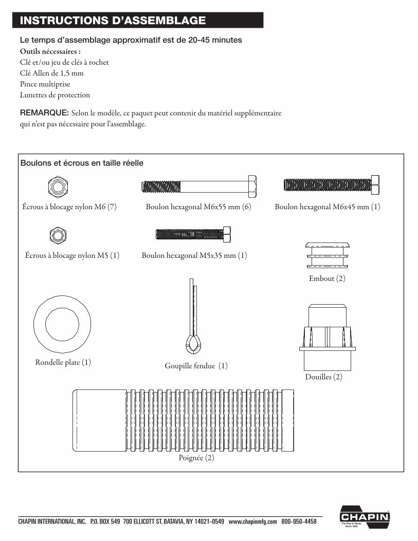
Boulons et écrous en taille réelle
Écrous à blocage nylon M5 (1)
Écrous à blocage nylon M6 (7) Boulon hexagonal M6x55 mm (6) Boulon hexagonal M6x45 mm (1)
Boulon hexagonal M5x35 mm (1)
Rondelle plate (1) Goupille fendue (1)
Embout (2)
Poignée (2)
Douilles (2)
INSTRUCTIONS D’ASSEMBLAGE
Outils nécessaires :Clé et/ou jeu de clés à rochetClé Allen de 1,5 mmPince multipriseLunettes de protection
Le temps d’assemblage approximatif est de 20-45 minutes
REMARQUE: Selon le modèle, ce paquet peut contenir du matériel supplémentaire quin’estpasnécessairepourl’assemblage.
CHAPIN INTERNATIONAL, INC. P.O. BOX 549 700 ELLICOTT ST. BATAVIA, NY 14021-0549 www.chapinmfg.com 800-950-4458
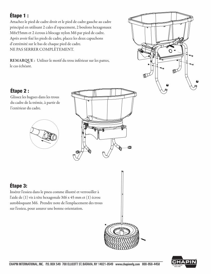
Étape 1 :Attachez le pied de cadre droit et le pied de cadre gauche au cadre principal en utilisant 2 cales d’espacement, 2 boulons hexagonaux M6x55mm et 2 écrous à blocage nylon M6 par pied de cadre. Aprèsavoirfixélespiedsdecadre,placezlesdeuxcapuchonsd’extrémité sur le bas de chaque pied de cadre. NE PAS SERRER COMPLÈTEMENT.
REMARQUE : Utiliser le motif du trou inférieur sur les pattes, le cas échéant.
Étape 2 :Glissez les bagues dans les trous du cadre de la trémie, à partir de l’extérieur du cadre.
Étape 3:Insérerl’essieudanslepneucommeillustréetverrouilleràl’aidede(1)visàtêtehexagonaleM6x45mmet(1)écrouautobloquantM6.Prendrenotedel’emplacementdestroussurl’essieu,pourassurerunebonneorientation.
CHAPIN INTERNATIONAL, INC. P.O. BOX 549 700 ELLICOTT ST. BATAVIA, NY 14021-0549 www.chapinmfg.com 800-950-4458
Bend
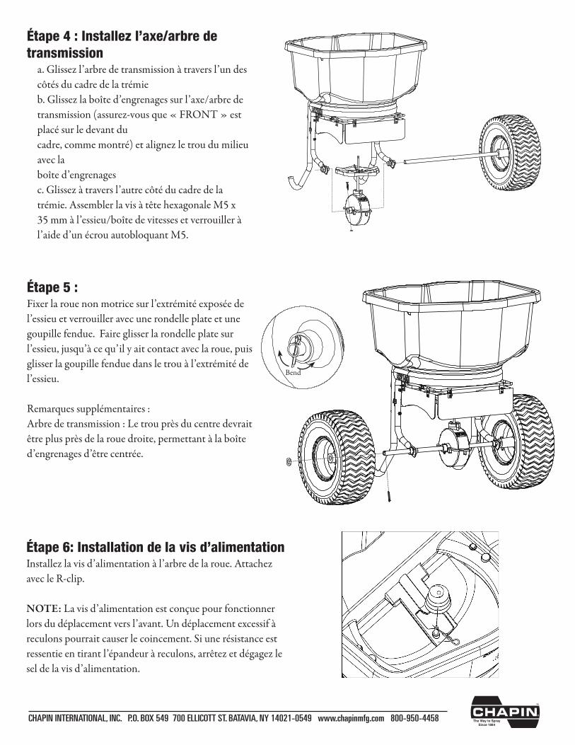
Étape 4 : Installez l’axe/arbre de transmission a. Glissez l’arbre de transmission à travers l’un des
côtés du cadre de la trémie b. Glissez la boîte d’engrenages sur l’axe/arbre de
transmission (assurez-vous que « FRONT » est placé sur le devant du cadre, comme montré) et alignez le trou du milieu avec la boîte d’engrenages
c. Glissez à travers l’autre côté du cadre de la trémie. AssemblerlavisàtêtehexagonaleM5x35 mm à l’essieu/boîte de vitesses et verrouiller à l’aide d’un écrou autobloquant M5.
Étape 5 :Fixer la roue non motrice sur l’extrémité exposée de l’essieu et verrouiller avec une rondelle plate et une goupille fendue. Faire glisser la rondelle plate sur l’essieu, jusqu’à ce qu’il y ait contact avec la roue, puis glisser la goupille fendue dans le trou à l’extrémité de l’essieu.
Remarques supplémentaires :Arbre de transmission : Le trou près du centre devrait êtreplusprèsdelarouedroite,permettantàlaboîted’engrenagesd’êtrecentrée.
Étape 6: Installation de la vis d’alimentationInstallez la vis d’alimentation à l’arbre de la roue. Attachez avec le R-clip.
NOTE: La vis d’alimentation est conçue pour fonctionner lors du déplacement vers l’avant. Un déplacement excessif à reculons pourrait causer le coincement. Si une résistance est ressentieentirantl’épandeuràreculons,arrêtezetdégagezlesel de la vis d’alimentation.
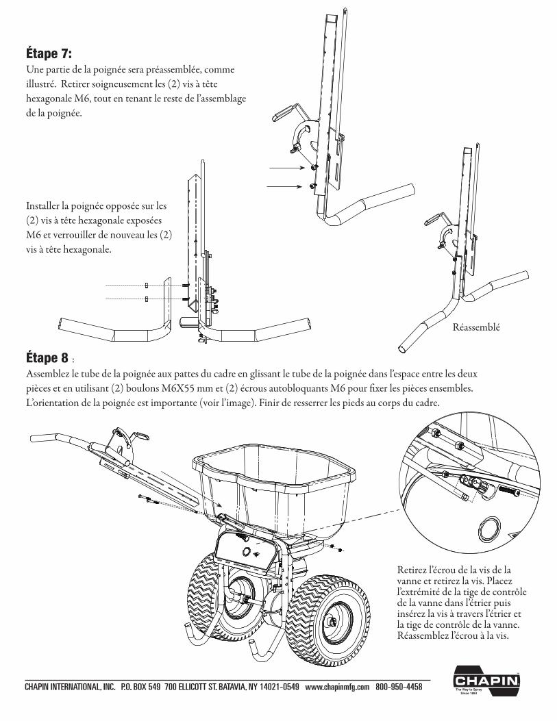
Étape 7: Une partie de la poignée sera préassemblée, comme illustré.Retirersoigneusementles(2)visàtêtehexagonaleM6,toutentenantlerestedel’assemblagede la poignée.
Installer la poignée opposée sur les (2)visàtêtehexagonaleexposéesM6 et verrouiller de nouveau les (2) visàtêtehexagonale.
CHAPIN INTERNATIONAL, INC. P.O. BOX 549 700 ELLICOTT ST. BATAVIA, NY 14021-0549 www.chapinmfg.com 800-950-4458
Réassemblé
Étape 8 :Assemblezletubedelapoignéeauxpattesducadreenglissantletubedelapoignéedansl’espaceentrelesdeuxpiècesetenutilisant(2)boulonsM6X55mmet(2)écrousautobloquantsM6pourfixerlespiècesensembles.L’orientationdelapoignéeestimportante(voirl’image).Finirderesserrerlespiedsaucorpsducadre.
Retirezl’écroudelavisdelavanne et retirez la vis. Placez l’extrémitédelatigedecontrôledelavannedansl’étrierpuisinsérezlavisàtraversl’étrieretla tige de contrôle de la vanne. Réassemblezl’écrouàlavis.
CHAPIN INTERNATIONAL, INC. P.O. BOX 549 700 ELLICOTT ST. BATAVIA, NY 14021-0549 www.chapinmfg.com 800-950-4458
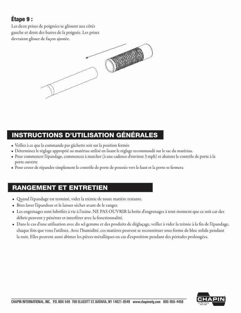
Étape 9 :Les deux prises de poignées se glissent aux côtés gauche et droit des barres de la poignée. Les prises devraient glisser de façon ajustée.
• Quandl’épandageestterminé,viderlatrémiedetoutematièrerestante.• Bienlaverl’épandeuretlelaissersécheravantdeleranger.• Lesengrenagessontlubrifiésàvieàl’usine.NEPASOUVRIRlaboîted’engrenagesàtoutmomentquecesoitcardes débris peuvent y pénétrer et interférer avec la fonctionnalité.• Danslecasd’uneutilisationavecduselgemmeetdesproduitsdedéglaçage,veilleràviderlatrémieàlafindel’épandage, chaquefoisquevousl’utilisez.Avecl’humidité,cesmatièrespeuventsereconstituersousformedeblocsolidependant lanuit.Ellespeuventaussiabîmerlespiècesmétalliquesencasd’expositionpendantdespériodesprolongées.
RANGEMENT ET ENTRETIEN
• Veillezàcequelacommandepargâchettesoitsurlapositionfermée•Déterminezleréglageappropriéaumatériauutiliséenlisantleréglagerecommandésurlesacdumatériau.• Pourcommencerl’épandage,commencezàmarcher(àunecadenced’environ3mph)etabaisserlecontrôledeporteàla porte ouverte• Pourcesserderépandresimplementlecontrôledeportedepousséeverslehautetlaportesefermera
INSTRUCTIONS D’UTILISATION GÉNÉRALES
CHAPIN INTERNATIONAL, INC. P.O. BOX 549 700 ELLICOTT ST. BATAVIA, NY 14021-0549 www.chapinmfg.com 800-950-4458
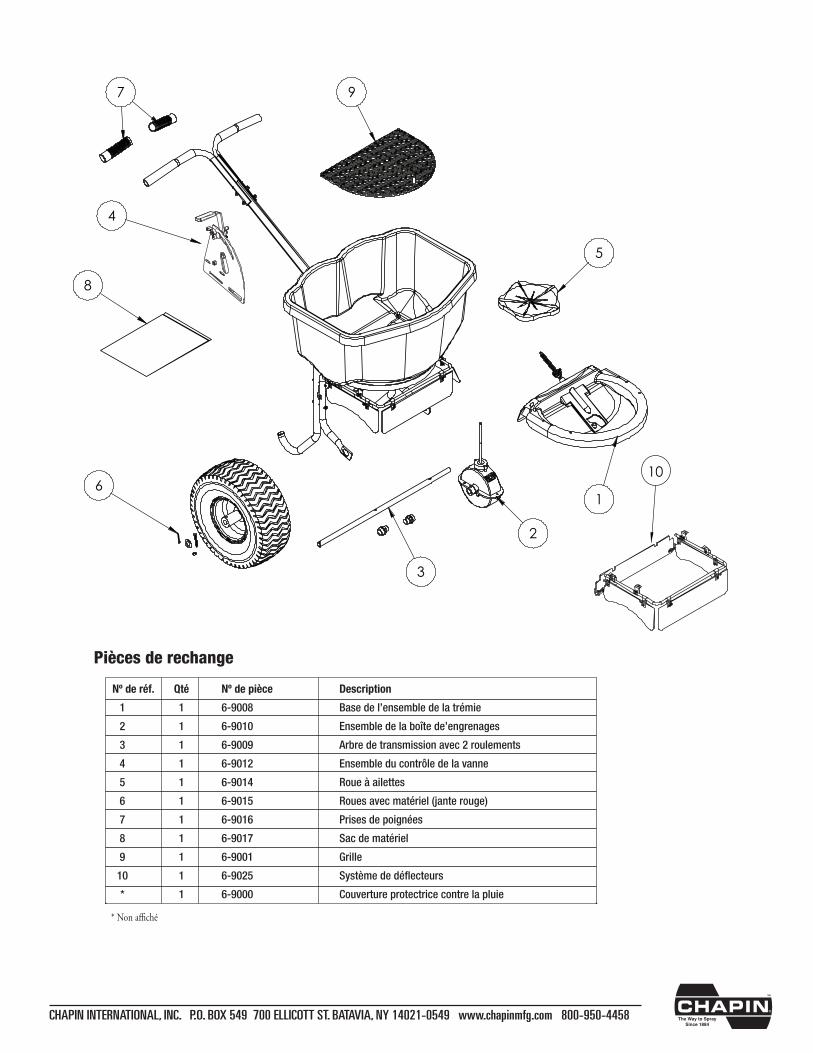
* Non affiché
Pièces de rechange
Nº de réf. Qté Nº de pièce Description
1 1 6-9008 Base de l’ensemble de la trémie
2 1 6-9010 Ensemble de la boîte de’engrenages
3 1 6-9009 Arbre de transmission avec 2 roulements
4 1 6-9012 Ensemble du contrôle de la vanne
5 1 6-9014 Roue à ailettes
6 1 6-9015 Roues avec matériel (jante rouge)
7 1 6-9016 Prises de poignées
8 1 6-9017 Sac de matériel
9 1 6-9001 Grille
10 1 6-9025 Système de déflecteurs
* 1 6-9000 Couverture protectrice contre la pluie
1
2
3
4
5
6
7
8
9
10
