production of methyl tertiary butyl ether (mtbe)
TRANSCRIPT
Kurdistan Regional Government
Ministry of Higher Education and Scientific Research
Koya University
Faculty of Engineering
Chemical Engineering Department
Author:
Alan Mawlud Amin
Aree Salah Tahir
Supervisor: Abdul Majid Osman
2015 - 2016
“A project submitted in partial fulfilment of the requirements for
the degree of bachelor in science in Chemical engineering at Koya
University”
PRODUCTION OF METHYL TERTIARY BUTYL ETHER (MTBE)
PRODUCTION OF METHYL TERTIARY BUTYL ETHER (MTBE)
I ABSTRACT
ABSTRACT
Methyl tertiary butyl ether (MTBE) is primarily used in gasoline blending as an
octane enhancer to improve hydrocarbon combustion efficiency. Of all the
Oxygenates, MTBE is the most attractive for a variety of technical reasons. It
has a low vapor pressure. It can be blended with other fuels without phase
separation. It has the desirable octane characteristics. MTBE is produced via
direct addition methanol to isobutylene using ion exchange resin as a catalyst.
In order to improve the quality of the gasoline produced in the Kurdistan
refineries, this project studies the implantation of an MTBE plant with a
capacity that suffices the production rate of Kurdistan gasoline.
The project based on conducting material and energy balances, designing
reaction and distillation equipment
According to this study, it is possible to obtain an overall conversion of around
80% with a purity of MTBE that reaches 95% and a payback period (PBP) that is
estimated to be 3.7 years.
Keywords: Production of MTBE, material balance, energy balance, process
design.
PRODUCTION OF METHYL TERTIARY BUTYL ETHER (MTBE)
II TABLE OF CONTENTS
1. TABLE OF CONTENTS
I. CHAPTER ONE: INTRODUCTION .................................. 1
Methyl tertiary butyl ether (MTBE)............................................................................. 1 1.1.
History of MTBE ........................................................................................................... 2 1.2.
Importance and applications of MTBE ........................................................................ 3 1.3.
Properties (chemical and physical) ............................................................................. 4 1.4.
1.5 World market demand ................................................................................................ 5 .
Objectives of this project ............................................................................................ 6 1.6.
II. CHAPTER TWO: MTBE PRODUCTION ........................... 7
Introduction................................................................................................................. 7 2.1.
Process Description ..................................................................................................... 8 2.2.
2.2.1. Possibility of Changing Process Feed Conditions .................................................... 9
Process Details .......................................................................................................... 11 2.3.
2.3.1. Equipment ............................................................................................................. 11
III. CHAPTER THREE: MATERIAL BALANCE ...................... 20
Introduction: ............................................................................................................. 20 3.1.
Calculations: .............................................................................................................. 21 3.2.
3.2.1. Over all material balance: ...................................................................................... 21
3.2.2. Material balance around reactor(R-901):.............................................................. 22
3.2.3. Material balance around distillation column (T-901): ........................................... 24
3.2.4. Material balance around methanol absorber (T-902):.......................................... 25
3.2.5. Material balance around tower (T-903): ............................................................... 26
IV. CHAPTER FOUR: ENERGY BALANCE .......................... 28
Introduction: ............................................................................................................. 28 4.1.
Conservation of energy: ............................................................................................ 28 4.2.
Energy balance calculations: ..................................................................................... 29 4.3.
4.3.1. Heat capacity equation for ideal gases: ................................................................ 29
4.3.2. Heat capacity constant for liquid: ......................................................................... 30
4.3.3. Energy balance around summing point: ............................................................... 30
PRODUCTION OF METHYL TERTIARY BUTYL ETHER (MTBE)
III TABLE OF CONTENTS
4.3.4. Energy balance around heat exchanger (E901): ................................................... 32
4.3.5. Energy balance around reactor (R901):................................................................. 34
4.3.6. Energy balance around distillation column (T901): .............................................. 36
4.3.7. Energy balance around methanol absorber (T902): ............................................. 39
V. CHAPTER FIVE: DESIGN ................................. 44
Distillation design: ..................................................................................................... 44 5.1.
5.1.1. Introduction: .......................................................................................................... 44
5.1.2. Collect the data of fluid to be distillated and distillated ....................................... 45
5.1.3. Heavy and light key:............................................................................................... 46
5.1.4. Type of tray: ........................................................................................................... 46
5.1.5. Determination of minimum reflux ratio: ............................................................... 47
5.1.6. Calculation of the actual ratio(R) ........................................................................... 48
5.1.7. Calculation of the minimum number of theoretical stages: ................................. 48
5.1.8. Calculation of the number of theoretical stages: .................................................. 48
5.1.9. Calculation of the column efficiency (E˳): ............................................................. 49
5.1.10. Calculation of the number of actual stages (Na): .............................................. 49
5.1.11. Calculation of the height of the column (Ht): .................................................... 49
5.1.12. Determination of the feed plate location (m): .................................................. 49
5.1.13. Calculation of the tower diameter(D): ............................................................... 50
5.1.14. Determination of fractional entrainment (ϕ): ................................................... 53
5.1.15. Weeping point: .................................................................................................. 53
5.1.16. Pressure drop calculation: ................................................................................. 54
5.1.17. Down comer liquid back up: .............................................................................. 55
5.1.18. Down comer residence time: ............................................................................. 56
VI. CHAPTER SIX: CONCLUSION & RECOMMENDATIONS ............................... 58
Conclusion: ................................................................................................................ 58 6.1.
Recommendations: ................................................................................................... 58 6.2.
VII. 7. ............................................................... REFERENCES 59
PRODUCTION OF METHYL TERTIARY BUTYL ETHER (MTBE)
IV TABLE OF CONTENTS
LIST OF FIGURES
Figure 1 Global MTBE Demand by Region (2014) .......................................................................... 6
Figure 2 MTBE Production Facility ................................................................................................ 10
LIST OF TABLES
Table 1 Properties of MTBE ............................................................................................................ 4
Table 2 MTBE competitive strengths and weaknesses .................................................................. 5
Table 3 Stream Tables for Unit 900 .............................................................................................. 14
Table 4 Utility Stream Flow Summary for Unit 900 ...................................................................... 17
Table 5 Partial Equipment Summary ............................................................................................ 18
Table 6 Reactors and Vessels ........................................................................................................ 18
Table 7 Pumps ............................................................................................................................... 18
Table 8 Towers .............................................................................................................................. 19
Table 9 Summary of material balance calculation by using Excel sheet ..................................... 27
Table 10 Heat capacity constants for ideal gases ......................................................................... 29
Table 11 Heat capacity constants for liquid. ................................................................................ 30
Table 12 summarizes the results: bubble point calculation of stream 15. .................................. 31
Table 13 Ratio of component (i) in the feed to isobutylene feed. ............................................... 34
Table 14 Summary of agent amount. ........................................................................................... 42
Table 15 Summary of energy balance calculation made by using Excel sheet ............................ 43
Table 16 Feed stream composition. ............................................................................................. 45
Table 17 Top stream composition ............................................................................................... 45
Table 18 Bottom stream composition .......................................................................................... 46
Table 19 Average relative volatility of composition. .................................................................... 46
Table 20 Summary of design calculation. ..................................................................................... 57
PRODUCTION OF METHYL TERTIARY BUTYL ETHER (MTBE)
1 INTRODUCTION
CHAPTER ONE 1. INTRODUCTION
Methyl tertiary butyl ether (MTBE) 1.1.
MTBE is a commonly used acronym for the chemical compound methyl
tertiary-butyl ether. At room temperature, MTBE is a volatile, flammable,
colorless liquid that is highly soluble in water. It is produced by the chemical
reaction of methanol, generally manufactured from natural gas, and
isobutylene. MTBE has a very distinct taste and odor, similar to turpentine.
MTBE has been used as a gasoline additive since 1979. However, MTBE was
not widely used as a gasoline additive in Connecticut until the mid-1980s and
was not discovered in our ground water until 1987. Initially, it was added to
gasoline as a. replacement for tetraethyl lead to increase the octane rating of
the fuel. This action has resulted in a. significant reduction in ambient air levels
of lead. As an octane enhancing additive, MTBE is blended into conventional
gasoline at concentrations ranging from approximately 3 to 5 percent, by
volume. More recently, MTBE has also been used as an oxygenate, an additive
that increases the oxygen content of gasoline. Oxygenates are added to
gasoline to produce more complete fitel combustion, resulting in reductions of
carbon monoxide and ozone forming emissions. As an oxygenate, MTBE is
currently blended into gasoline at concentrations ranging from 2.0 to 2.7
percent weight oxygen, the equivalent of 11 to 15 percent MTBE, by volume
(Rocque, 2000).
PRODUCTION OF METHYL TERTIARY BUTYL ETHER (MTBE)
2 INTRODUCTION
History of MTBE 1.2.
In the late 1970s and 1980s, oxygenates such as MTBE and ethanol were added
to fuels to improve efficiency while meeting lead phase-out requirements. The
use of MTBE became prevalent because of its low cost, ease of production, and
favorable transfer and blending characteristics. Other less commonly used
oxygenates include methanol, ethyl tertiary-butyl ether (ETBE), tertiary-amyl
methyl ether (TAME), diisopropyl ether (DIPE), and tertiary-butyl alcohol (TBA).
In 1987, the Colorado Air Quality Control Commission adopted the first
regulations in the country requiring that oxygenated fuels be sold along much
of the Colorado Front Range. The purpose of the oxygenated fuels program
was to make gasoline burn more cleanly in order to reduce air emissions and
smog.
Based in part on the successful oxygenated fuels program that had been
ongoing along the Colorado Front Range, the Clean Air Act Amendments of
1990 required that oxygenated fuels be used at service stations and gasoline
retail businesses in regions of the United States where ozone or carbon
monoxide air quality standards were exceeded. Beginning in 1992, the winter
oxygenated fuel program required 2.7% oxygen by weight in gasoline
(equivalent to 15% MTBE or 7.3% ethanol by volume) in 40 U.S. metropolitan
areas, including those located along the Colorado Front Range. In 1995, the
U.S. implemented Reformulated Gasoline Phase I, requiring 2.0% oxygen by
weight in gasoline year-round in 28 U.S. metropolitan areas. Reformulated
Gasoline Phase II, beginning January 1, 2000, continued to require 2.0% oxygen
by weight.
As a result of concerns regarding MTBE (Section 3.0), efforts have been made
in several States to discontinue the use of MTBE in gasoline. As of June 2004,
PRODUCTION OF METHYL TERTIARY BUTYL ETHER (MTBE)
3 INTRODUCTION
legislation that would partially or completely ban or restrict the use of MTBE in
gasoline has been passed in 19 states. Colorado Senate Bill 190 was signed into
law on May 23, 2000 ordering the phase-out of MTBE as a fuel component or
additive by April 30, 2002. This legislation declared “it is the intent of the
general assembly…to halt further contamination and pollution of this state’s
groundwater supplies by MTBE” (Lidderdale, 2000).
Importance and applications of MTBE 1.3.
As anti-knocking agent
In the US it has been used in gasoline at low levels since 1979 to
replace tetraethyl lead and to increase its octane rating helping
prevent engine knocking. Oxygenates help gasoline burn more
completely, reducing tailpipe emissions from pre-1984 motor vehicles;
dilutes or displaces gasoline components such as aromatics
(e.g., benzene) and sulfur; and optimizes the oxidation during
combustion. Most refiners chose MTBE over other oxygenates primarily
for its blending characteristics and low cost.
As a solvent
Despite the popularity of MTBE in industrial settings, it is rarely used as a
solvent in academia with some exceptions.
MTBE forms azeotropes with water (52.6 °C; 96.5% MTBE) and methanol
(51.3 °C; 68.6% MTBE).
Although an ether, MTBE is a poor Lewis base and does not support
formation of Grignard reagents. It is also unstable toward strong acids. It
reacts dangerously with bromine (Winterberg, et al., 2010).
PRODUCTION OF METHYL TERTIARY BUTYL ETHER (MTBE)
4 INTRODUCTION
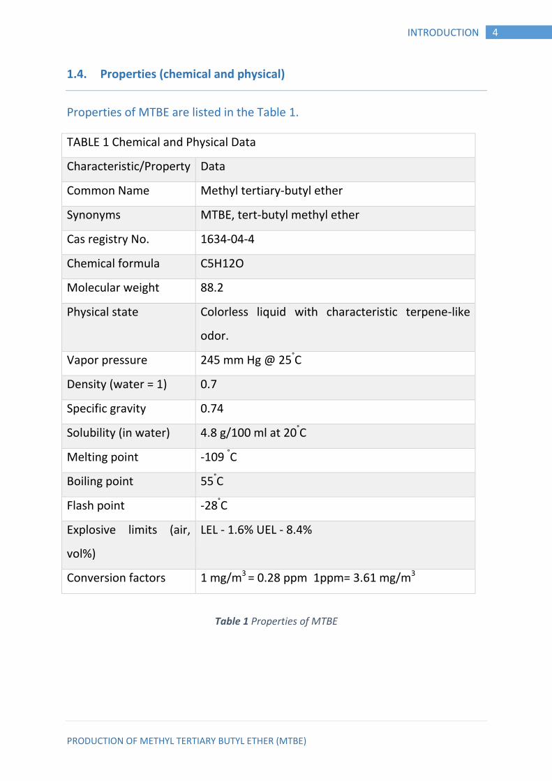
Properties (chemical and physical) 1.4.
Properties of MTBE are listed in the Table 1.
TABLE 1 Chemical and Physical Data
Characteristic/Property Data
Common Name Methyl tertiary-butyl ether
Synonyms MTBE, tert-butyl methyl ether
Cas registry No. 1634-04-4
Chemical formula C5H12O
Molecular weight 88.2
Physical state Colorless liquid with characteristic terpene-like
odor.
Vapor pressure 245 mm Hg @ 25°C
Density (water = 1) 0.7
Specific gravity 0.74
Solubility (in water) 4.8 g/100 ml at 20°C
Melting point -109 °C
Boiling point 55°C
Flash point -28°C
Explosive limits (air,
vol%)
LEL - 1.6% UEL - 8.4%
Conversion factors 1 mg/m3 = 0.28 ppm 1ppm= 3.61 mg/m3
Table 1 Properties of MTBE
PRODUCTION OF METHYL TERTIARY BUTYL ETHER (MTBE)
5 INTRODUCTION
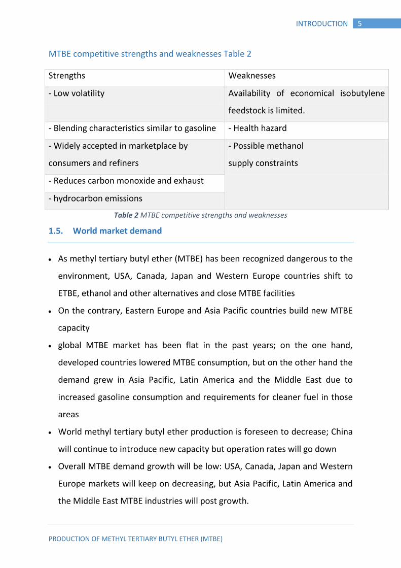
MTBE competitive strengths and weaknesses Table 2
Strengths Weaknesses
- Low volatility Availability of economical isobutylene
feedstock is limited.
- Blending characteristics similar to gasoline - Health hazard
- Widely accepted in marketplace by
consumers and refiners
- Possible methanol
supply constraints
- Reduces carbon monoxide and exhaust
- hydrocarbon emissions
Table 2 MTBE competitive strengths and weaknesses
World market demand 1.5.
As methyl tertiary butyl ether (MTBE) has been recognized dangerous to the
environment, USA, Canada, Japan and Western Europe countries shift to
ETBE, ethanol and other alternatives and close MTBE facilities
On the contrary, Eastern Europe and Asia Pacific countries build new MTBE
capacity
global MTBE market has been flat in the past years; on the one hand,
developed countries lowered MTBE consumption, but on the other hand the
demand grew in Asia Pacific, Latin America and the Middle East due to
increased gasoline consumption and requirements for cleaner fuel in those
areas
World methyl tertiary butyl ether production is foreseen to decrease; China
will continue to introduce new capacity but operation rates will go down
Overall MTBE demand growth will be low: USA, Canada, Japan and Western
Europe markets will keep on decreasing, but Asia Pacific, Latin America and
the Middle East MTBE industries will post growth.
PRODUCTION OF METHYL TERTIARY BUTYL ETHER (MTBE)
6 INTRODUCTION
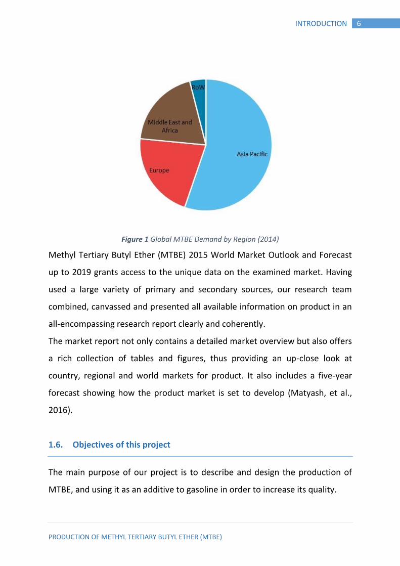
Figure 1 Global MTBE Demand by Region (2014)
Methyl Tertiary Butyl Ether (MTBE) 2015 World Market Outlook and Forecast
up to 2019 grants access to the unique data on the examined market. Having
used a large variety of primary and secondary sources, our research team
combined, canvassed and presented all available information on product in an
all-encompassing research report clearly and coherently.
The market report not only contains a detailed market overview but also offers
a rich collection of tables and figures, thus providing an up-close look at
country, regional and world markets for product. It also includes a five-year
forecast showing how the product market is set to develop (Matyash, et al.,
2016).
Objectives of this project 1.6.
The main purpose of our project is to describe and design the production of
MTBE, and using it as an additive to gasoline in order to increase its quality.
PRODUCTION OF METHYL TERTIARY BUTYL ETHER (MTBE)
7 MTBE PRODUCTION
CHAPTER TWO 2. MTBE PRODUCTION
Introduction 2.1.
We work at this plant to produce 112,200tons / year (112,200,000 kg/y) of
methyl tertiary butyl ether (MTBE). MTBE is an oxygenated fuel additive that is
blended with gasoline to promote CO2 formation over CO formation during
combustion. The facility manufactures MTBE from methanol and isobutylene.
Isobutylene is obtained from a refinery cut, and it also contains 1-butene and
2-butene, both of which do not react with methanol.
Process Selection
MTBE is produced via direct addition of methanol to isobutylene using
sulphonated ion
Exchange resin as catalysts.
There are two ways to produce MTBE:
Conventional Process
Which is mainly a reactor and separate distillation column with
conversion range 87 - 92%.
Reactive Distillation Process
It’s a newly method for the production of MTBE which is established and
date back to the way in 1980 as the scientist Smith recorded the first
patent for the production of MTBE, through this method, this method
called Reactive Distillation Process, and there are a lot of features that
makes this process attractive and practical with a conversion reached
PRODUCTION OF METHYL TERTIARY BUTYL ETHER (MTBE)
8 MTBE PRODUCTION
99.2%. The process which we select in our project is Reactive Distillation
Process because it has more conversion rate of MTBE.
Process Description 2.2.
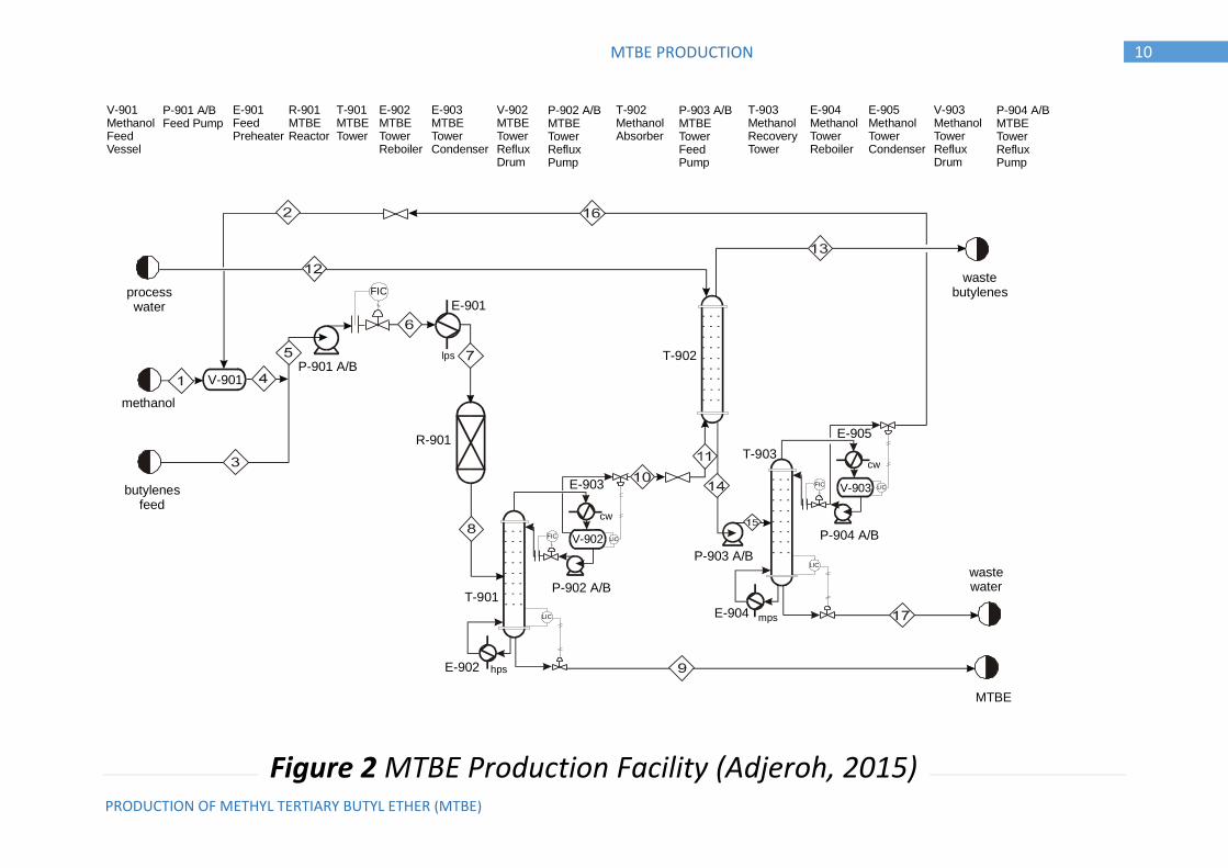
The process flow diagram is shown in Figure 2 Methanol and the mixed
butylenes feed is pumped and heated to reaction conditions. Both the
methanol and the mixed butylenes are made in on-site units, and are sent to
this unit at the desired conditions. The reactor operates in the vicinity of 30
bar, to ensure that the reaction occurs in the liquid phase. The reaction is
reversible. The feed temperature to the reactor is usually maintained below
90C to obtain favorable equilibrium behavior. Any side reactions involving 1-
butene and 2-butene form small amounts of products with similar fuel
blending characteristics, so side reactions are assumed to be unimportant.
Other side reactions are minimized by keeping the methanol present in excess.
The reactor effluent is distilled, with MTBE as the bottom product. Methanol is
recovered from the mixed butylenes in a water scrubber, and the methanol is
subsequently separated from water so that unreacted methanol can be
recycled. Unreacted butylenes are sent back to the refinery for further
processing. The MTBE product is further purified (not shown), mostly to
remove the trace amounts of water. The product stream from Unit 900 must
contain at least 94 mol % MTBE, with the MTBE portion of the stream flowrate
at specifications (Al-Harthi, 2008.).
Tables 3 and 4 contain the stream and utility flows for the process as designed.
Table 5, 6, 7 and 8 contains an equipment list other pertinent information and
calculations are obtained based on Chemical Engineering books.
PRODUCTION OF METHYL TERTIARY BUTYL ETHER (MTBE)
9 MTBE PRODUCTION
2.2.1. Possibility of Changing Process Feed Conditions
This plant receives the mixed butylenes feed from a neighboring refinery,
which has recently changed ownership. The new owners are planning to
implement changes based on their proprietary technology. The changes will
occur after a regularly scheduled plant shut down (for both plants) within the
next six months. The effect on our plant is that they have proposed that the
mixed butylenes feed that we receive will contain 23 wt% isobutylene
(isobutene), 20 wt% 1-butene, and 57 wt% 2-butene. Our current contract for
mixed butylenes expires at the next plant shut down, so we are in the process
of negotiating a new contract with the new owners. An additional
complication is that MTBE is in the process of being phased out as a fuel
additive because of ground water contamination from leaky gasoline storage
tanks.
PRODUCTION OF METHYL TERTIARY BUTYL ETHER (MTBE)
10 MTBE PRODUCTION
FIC
FIC
FIC
cw
cw
hps
lps
mps
LIC
LIC
LIC
LIC
butylenesfeed
methanol
processwater
wastebutylenes
wastewater
MTBE
V-903
V-902
V-901P-901 A/B
P-903 A/B
P-902 A/B
P-904 A/B
E-902
E-904
E-905
E-903
E-901
R-901
T-901
T-902
T-903
Figure 1: Unit 900 - MTBE Production Facility
V-901MethanolFeed Vessel
P-901 A/BFeed Pump
E-901FeedPreheater
R-901MTBEReactor
T-901MTBETower
T-903MethanolRecoveryTower
T-902MethanolAbsorber
E-902MTBETowerReboiler
E-904MethanolTowerReboiler
E-903MTBETowerCondenser
E-905MethanolTowerCondenser
V-902MTBETowerRefluxDrum
V-903MethanolTowerRefluxDrum
P-902 A/BMTBETowerRefluxPump
P-904 A/BMTBETowerRefluxPump
P-903 A/BMTBETowerFeedPump
Figure 2 MTBE Production Facility (Adjeroh, 2015)
PRODUCTION OF METHYL TERTIARY BUTYL ETHER (MTBE)
11 MTBE PRODUCTION
Process Details 2.3.
Feed Stream and Effluent Streams
Stream 1: Methanol – stored as a liquid at the desired pressure of the
reaction.
Stream 2: Mixed butene stream – 23% isobutene, 20% 1-butene, 57% 2-
butene.
Stream 8: MTBE product – must be 95 wt% pure.
Stream 11: Process water – see utility list for more information
Stream 12: Waste butenes – returned to refinery – contains 1-butene and 2-
butene with less than 1 wt% other impurities.
Stream 16: Waste water – must be treated – must contain 99 wt% water –
See the utility list for more information (Winterberg, et al., 2010).
2.3.1. Equipment
Pump (P-901 A/B, includes spare pump)
The pump increases the pressure of the mixed feed to the reaction conditions.
The liquid density may be estimated using a linear average of the pure
component densities, weighted by their mass fractions in the mixture. The
cost of electricity to run the pump is a utility cost based on the required power
for the pump. The required power is the work multiplied by the mass flowrate
of Stream 4.
Heat Exchanger (E-901)
This heat exchanger heats the feed to the reactor feed temperature. Each
component must remain in the liquid phase at the chosen pressure. The cost
of the heat source is a utility cost.
PRODUCTION OF METHYL TERTIARY BUTYL ETHER (MTBE)
12 MTBE PRODUCTION
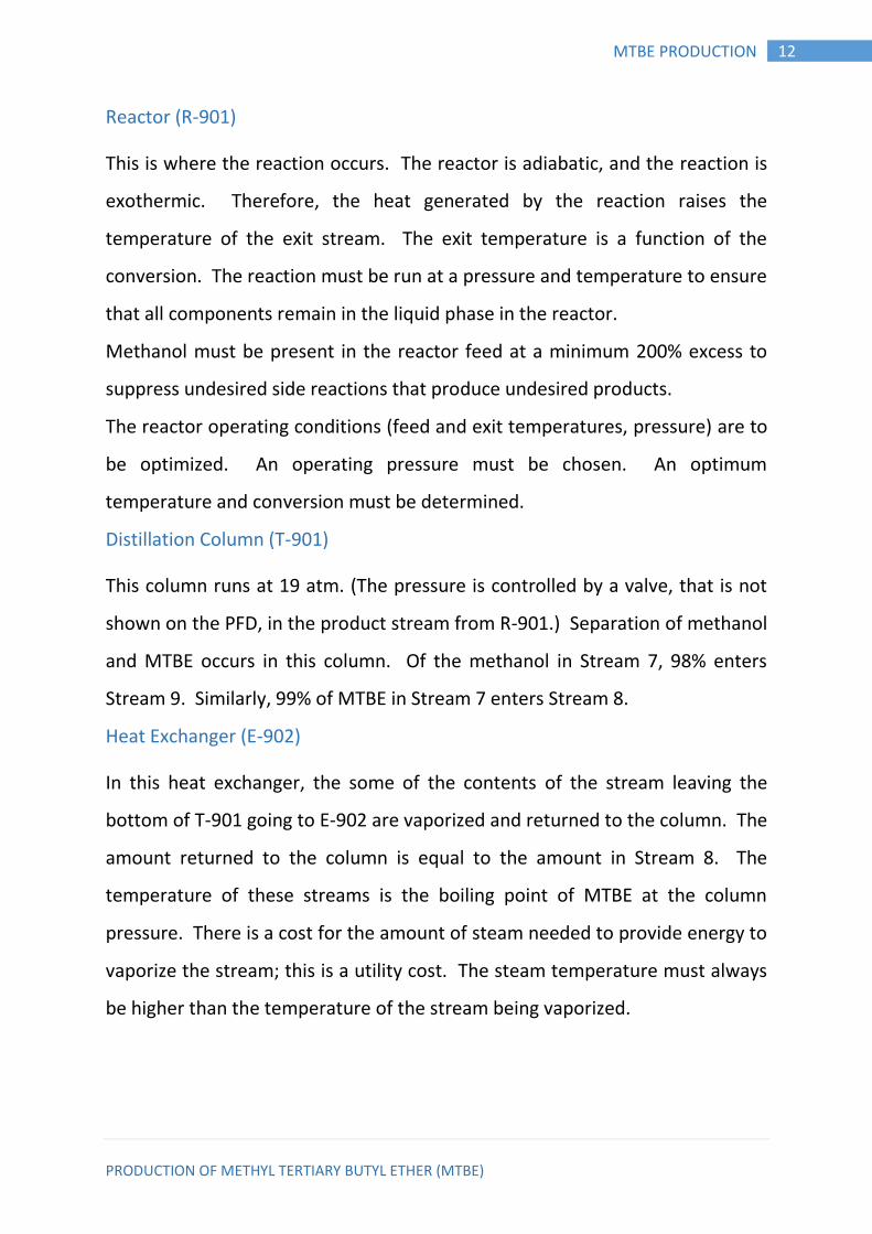
Reactor (R-901)
This is where the reaction occurs. The reactor is adiabatic, and the reaction is
exothermic. Therefore, the heat generated by the reaction raises the
temperature of the exit stream. The exit temperature is a function of the
conversion. The reaction must be run at a pressure and temperature to ensure
that all components remain in the liquid phase in the reactor.
Methanol must be present in the reactor feed at a minimum 200% excess to
suppress undesired side reactions that produce undesired products.
The reactor operating conditions (feed and exit temperatures, pressure) are to
be optimized. An operating pressure must be chosen. An optimum
temperature and conversion must be determined.
Distillation Column (T-901)
This column runs at 19 atm. (The pressure is controlled by a valve, that is not
shown on the PFD, in the product stream from R-901.) Separation of methanol
and MTBE occurs in this column. Of the methanol in Stream 7, 98% enters
Stream 9. Similarly, 99% of MTBE in Stream 7 enters Stream 8.
Heat Exchanger (E-902)
In this heat exchanger, the some of the contents of the stream leaving the
bottom of T-901 going to E-902 are vaporized and returned to the column. The
amount returned to the column is equal to the amount in Stream 8. The
temperature of these streams is the boiling point of MTBE at the column
pressure. There is a cost for the amount of steam needed to provide energy to
vaporize the stream; this is a utility cost. The steam temperature must always
be higher than the temperature of the stream being vaporized.
PRODUCTION OF METHYL TERTIARY BUTYL ETHER (MTBE)
13 MTBE PRODUCTION
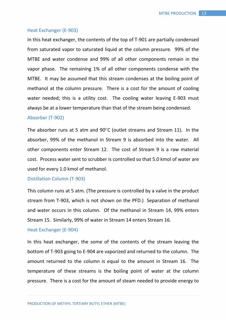
Heat Exchanger (E-903)
In this heat exchanger, the contents of the top of T-901 are partially condensed
from saturated vapor to saturated liquid at the column pressure. 99% of the
MTBE and water condense and 99% of all other components remain in the
vapor phase. The remaining 1% of all other components condense with the
MTBE. It may be assumed that this stream condenses at the boiling point of
methanol at the column pressure. There is a cost for the amount of cooling
water needed; this is a utility cost. The cooling water leaving E-903 must
always be at a lower temperature than that of the stream being condensed.
Absorber (T-902)
The absorber runs at 5 atm and 90C (outlet streams and Stream 11). In the
absorber, 99% of the methanol in Stream 9 is absorbed into the water. All
other components enter Stream 12. The cost of Stream 9 is a raw material
cost. Process water sent to scrubber is controlled so that 5.0 kmol of water are
used for every 1.0 kmol of methanol.
Distillation Column (T-903)
This column runs at 5 atm. (The pressure is controlled by a valve in the product
stream from T-903, which is not shown on the PFD.) Separation of methanol
and water occurs in this column. Of the methanol in Stream 14, 99% enters
Stream 15. Similarly, 99% of water in Stream 14 enters Stream 16.
Heat Exchanger (E-904)
In this heat exchanger, the some of the contents of the stream leaving the
bottom of T-903 going to E-904 are vaporized and returned to the column. The
amount returned to the column is equal to the amount in Stream 16. The
temperature of these streams is the boiling point of water at the column
pressure. There is a cost for the amount of steam needed to provide energy to
PRODUCTION OF METHYL TERTIARY BUTYL ETHER (MTBE)
14 MTBE PRODUCTION
vaporize the stream; this is a utility cost. The steam temperature must always
be higher than the temperature of the stream being vaporized.
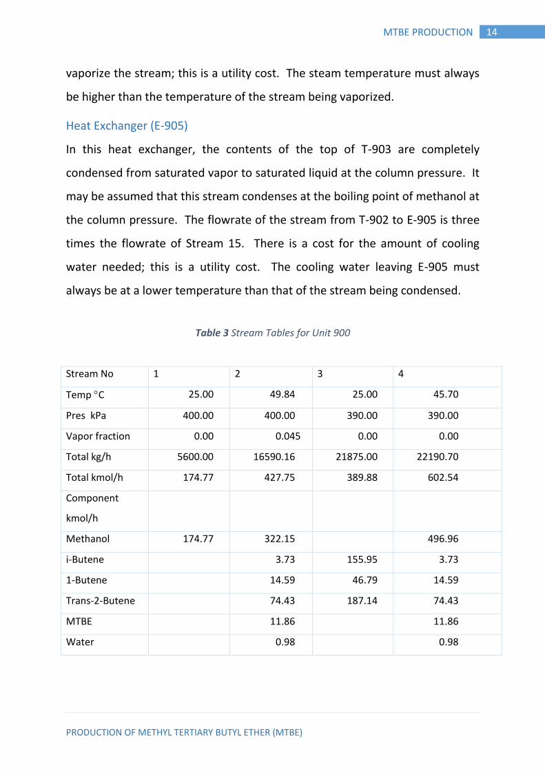
Heat Exchanger (E-905)
In this heat exchanger, the contents of the top of T-903 are completely
condensed from saturated vapor to saturated liquid at the column pressure. It
may be assumed that this stream condenses at the boiling point of methanol at
the column pressure. The flowrate of the stream from T-902 to E-905 is three
times the flowrate of Stream 15. There is a cost for the amount of cooling
water needed; this is a utility cost. The cooling water leaving E-905 must
always be at a lower temperature than that of the stream being condensed.
Table 3 Stream Tables for Unit 900
Stream No 1 2 3 4
Temp C 25.00 49.84 25.00 45.70
Pres kPa 400.00 400.00 390.00 390.00
Vapor fraction 0.00 0.045 0.00 0.00
Total kg/h 5600.00 16590.16 21875.00 22190.70
Total kmol/h 174.77 427.75 389.88 602.54
Component
kmol/h
Methanol 174.77 322.15 496.96
i-Butene 3.73 155.95 3.73
1-Butene 14.59 46.79 14.59
Trans-2-Butene 74.43 187.14 74.43
MTBE 11.86 11.86
Water 0.98 0.98

PRODUCTION OF METHYL TERTIARY BUTYL ETHER (MTBE)
15 MTBE PRODUCTION
Stream No. 5 6 7 8
Temp C 25.93 26.91 85.00 127.57
Pres kPa 380.00 3000.00 2965.00 2915.00
Vapor fraction 0.00 0.00 0.00 0.00
Total kmol/h 992.42 992.42 992.42 848.70
Total kg/h 44065.70 44065.70 44065.70 44065.70
Component
kmol/h
Methanol 496.96 496.96 496.96 353.23
i-Butene 159.68 159.68 159.68 15.95
1-Butene 61.38 61.38 61.38 61.38
Trans-2-Butene 261.58 261.58 261.58 261.58
MTBE 11.86 11.860 11.86 155.59
Water 0.97 0.97 0.97 0.97
Stream No. 9 10 11 12
Temp C 178.46 134.37 110.36 30.00
Pres kPa 1925.00 1900.00 500.00 450.00
Vapor fraction 0.00 1.00 1.00 0.00
Total kg/h 12973.05 31272.80 31272.80 21618.00
Total kmol/h 150.40 698.30 698.30 1200.00
Component kmol/h
Methanol 7.06 346.17 346.17
i-Butene 0.00 15.95 15.95
1-Butene 0.00 61.38 61.38
Trans-2-Butene 0.00 261.58 261.58
MTBE 142.36 13.22 13.22
Water 0.97 0.00 0.00 1200.00
PRODUCTION OF METHYL TERTIARY BUTYL ETHER (MTBE)
16 MTBE PRODUCTION
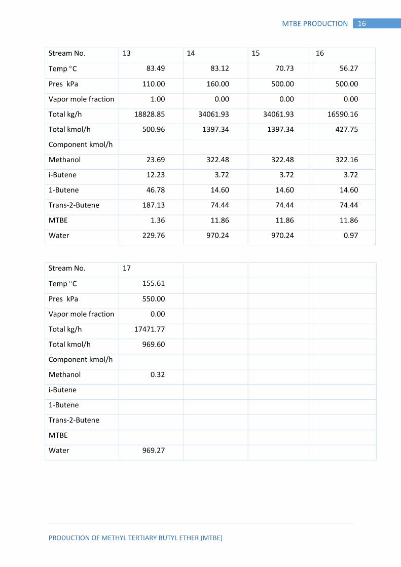
Stream No. 13 14 15 16
Temp C 83.49 83.12 70.73 56.27
Pres kPa 110.00 160.00 500.00 500.00
Vapor mole fraction 1.00 0.00 0.00 0.00
Total kg/h 18828.85 34061.93 34061.93 16590.16
Total kmol/h 500.96 1397.34 1397.34 427.75
Component kmol/h
Methanol 23.69 322.48 322.48 322.16
i-Butene 12.23 3.72 3.72 3.72
1-Butene 46.78 14.60 14.60 14.60
Trans-2-Butene 187.13 74.44 74.44 74.44
MTBE 1.36 11.86 11.86 11.86
Water 229.76 970.24 970.24 0.97
Stream No. 17
Temp C 155.61
Pres kPa 550.00
Vapor mole fraction 0.00
Total kg/h 17471.77
Total kmol/h 969.60
Component kmol/h
Methanol 0.32
i-Butene
1-Butene
Trans-2-Butene
MTBE
Water 969.27
PRODUCTION OF METHYL TERTIARY BUTYL ETHER (MTBE)
17 MTBE PRODUCTION
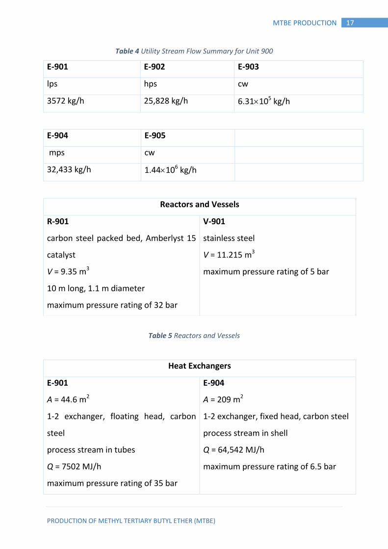
Table 4 Utility Stream Flow Summary for Unit 900
E-901 E-902 E-903
lps hps cw
3572 kg/h 25,828 kg/h 6.31105 kg/h
E-904 E-905
mps cw
32,433 kg/h 1.44106 kg/h
Table 5 Reactors and Vessels
Heat Exchangers
E-901
A = 44.6 m2
1-2 exchanger, floating head, carbon
steel
process stream in tubes
Q = 7502 MJ/h
maximum pressure rating of 35 bar
E-904
A = 209 m2
1-2 exchanger, fixed head, carbon steel
process stream in shell
Q = 64,542 MJ/h
maximum pressure rating of 6.5 bar
Reactors and Vessels
R-901
carbon steel packed bed, Amberlyst 15
catalyst
V = 9.35 m3
10 m long, 1.1 m diameter
maximum pressure rating of 32 bar
V-901
stainless steel
V = 11.215 m3
maximum pressure rating of 5 bar
PRODUCTION OF METHYL TERTIARY BUTYL ETHER (MTBE)
18 MTBE PRODUCTION
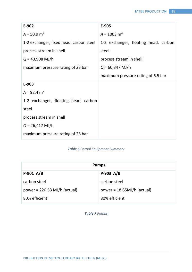
E-902
A = 50.9 m2
1-2 exchanger, fixed head, carbon steel
process stream in shell
Q = 43,908 MJ/h
maximum pressure rating of 23 bar
E-905
A = 1003 m2
1-2 exchanger, floating head, carbon
steel
process stream in shell
Q = 60,347 MJ/h
maximum pressure rating of 6.5 bar
E-903
A = 92.4 m2
1-2 exchanger, floating head, carbon
steel
process stream in shell
Q = 26,417 MJ/h
maximum pressure rating of 23 bar
Table 6 Partial Equipment Summary
Pumps
P-901 A/B
carbon steel
power = 220.53 MJ/h (actual)
80% efficient
P-903 A/B
carbon steel
power = 18.65MJ/h (actual)
80% efficient
Table 7 Pumps
PRODUCTION OF METHYL TERTIARY BUTYL ETHER (MTBE)
19 MTBE PRODUCTION
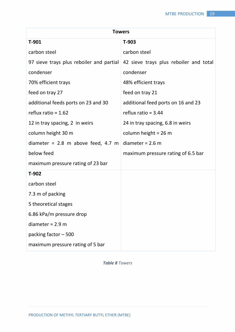
Towers
T-901
carbon steel
97 sieve trays plus reboiler and partial
condenser
70% efficient trays
feed on tray 27
additional feeds ports on 23 and 30
reflux ratio = 1.62
12 in tray spacing, 2 in weirs
column height 30 m
diameter = 2.8 m above feed, 4.7 m
below feed
maximum pressure rating of 23 bar
T-903
carbon steel
42 sieve trays plus reboiler and total
condenser
48% efficient trays
feed on tray 21
additional feed ports on 16 and 23
reflux ratio = 3.44
24 in tray spacing, 6.8 in weirs
column height = 26 m
diameter = 2.6 m
maximum pressure rating of 6.5 bar
T-902
carbon steel
7.3 m of packing
5 theoretical stages
6.86 kPa/m pressure drop
diameter = 2.9 m
packing factor – 500
maximum pressure rating of 5 bar
Table 8 Towers
PRODUCTION OF METHYL TERTIARY BUTYL ETHER (MTBE)
20 MATERIAL BALANCE
CHAPTER THREE 3. MATERIAL BALANCE
Introduction: 3.1.
The material balance taken over the complete process will determine the
quantities of raw materials required and products produced. Balance over
individual process units set the process stream flow and composition. A good
understanding of material balance calculation is essential in process design.
Material balance are also useful tools for the study of plant operation and
trouble shooting. They can be used to check performance against design; to
extend the often limited data available from plant instrumentation; to check
instrument calibrations; and to locate sources of material loss (Himmelblau &
Riggs, 2004).
The general conservation equation for any process system can be written as:
Material out =material in+ generation –consumption –accumulation
ASSUMPTIONS:
The material balance calculation will be based on the following assumption: -
The basis one hour.
The plant works 330 day in a year and 24 hour per day. -steady state
operation.
Single pass conversion is 80%.
The material balance calculation will be based on flow sheet in figure 2.
PRODUCTION OF METHYL TERTIARY BUTYL ETHER (MTBE)
21 MATERIAL BALANCE
Symbols used in this chapter:
Total mole flow of stream i
MTBEi, Mi, Wi, ISOi, BUTEi ≡ Mole fraction of MTBE, Methanol, Water,
isobutene and butene respectively.
Calculations: 3.2.
Amount of stream 8 =1660 Kmol
Average molecular weight of stream 8:
= MW (MTBE) × mMTBE+ MW (Methanol) × mmeth
= 88.15×0.95 + 32.04×0.05 = 85.34 kg/kmol
3.2.1. Over all material balance:
F1+F2+F11 = F8+F12+F16
Methanol balance:
F1 ∗ 1+F2 ∗ 0+F11 ∗ 0 = F8 ∗ 0+F12 ∗ 0+F16 ∗ 0.03 + 1747.37 ∗ 0.05 + 1660 F1-
0.03F16 =1747.3685
Isobutylene balance:
F1 ∗ 0+F2 ∗ ISO2+F11 ∗ 0 = F8 ∗ 0+F12 ∗ ISO12+F16 ∗ 0 + 1660 0.23F2 − ISO12F12 =
1660
Water balance:
F1 ∗ 0+F2 ∗ 0+F11 ∗ 1 = F8 ∗ 0+F12 ∗ 0+F16 ∗ 0.97
F11 − 0.97F16=0
PRODUCTION OF METHYL TERTIARY BUTYL ETHER (MTBE)
22 MATERIAL BALANCE
Other butane balance:
F1 ∗ 0+F2 ∗ 0.77+F11 ∗ 0 = F8 ∗ 0+F12 ∗ BUTE12+F16 ∗ 0
F2 ∗ 0.77-BUTE 12F12=0
F1+F15 = F3
Methanol balance:
F1 ∗ 1+F15 ∗ 1 = F3∗1
F2+F3 = F4
Methanol balance:
F2 ∗ 0+F3 ∗ 1 = F4 ∗ M4
Isobutene:
F2 ∗ 0.23+F3 ∗ 0 = F4 ∗ ISO4
Other butane:
F2 ∗ 0.77+F3 ∗ 0 = F4 ∗ BUTE4
F4 = F5 = F6
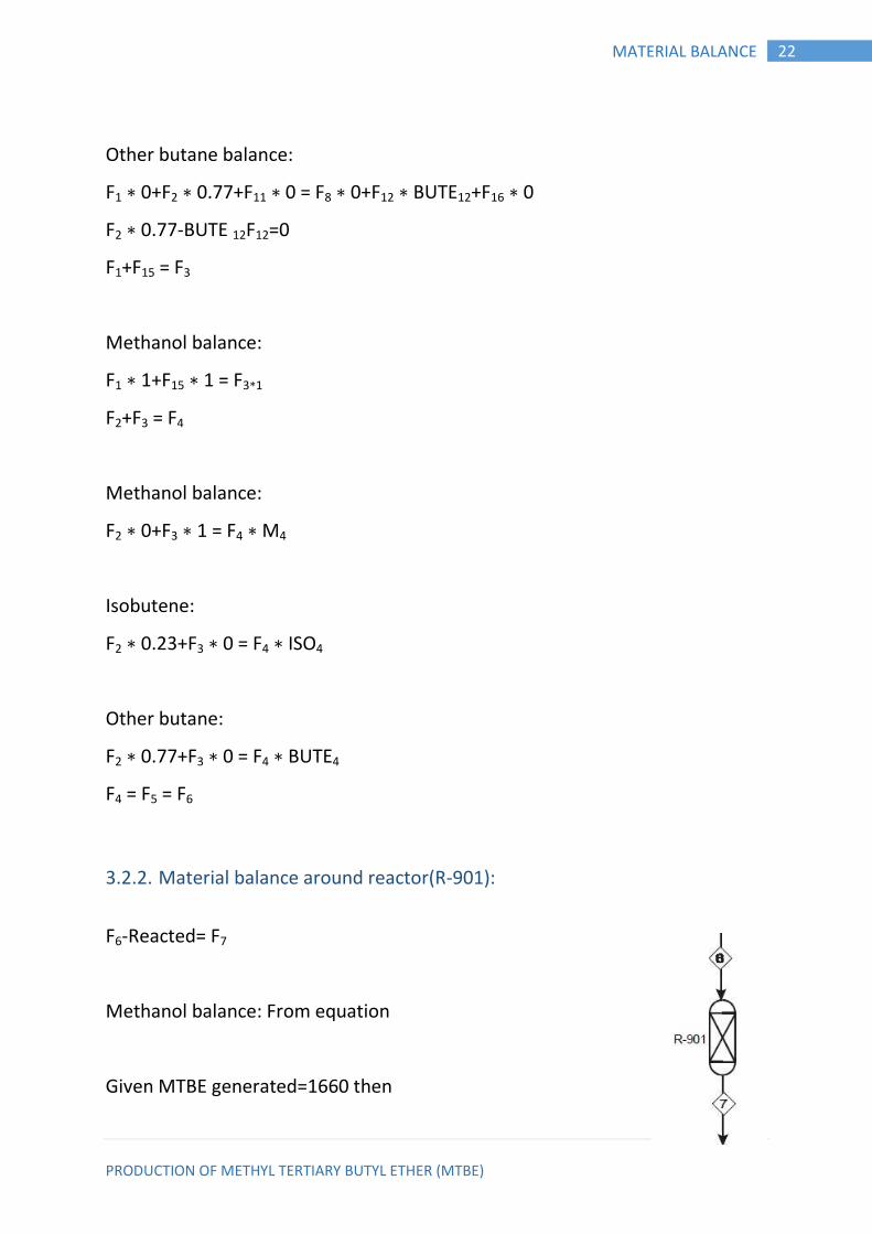
3.2.2. Material balance around reactor(R-901):
F6-Reacted= F7
Methanol balance: From equation
Given MTBE generated=1660 then
PRODUCTION OF METHYL TERTIARY BUTYL ETHER (MTBE)
23 MATERIAL BALANCE
mmeth F6 – 1660 = M7F7
Isobutene:
misoF6-1660= ISO7F7
misoF6=
2088.05-1660=ISO7F7 = 428.05
Butane balance:
BUTE6F6 = BUTE7F7
MTBE balance:
0∗F6-1660=MTBE7F7
MTBE7F7 =1660
Note:
At stream F6:
(2*ISO)*F6=4176.1
4176.1-1660=M7F7 =2516.10
Given:
At F2: ISO2 = 32%, BUTE2= 77%
Amount of ISO =2088.05
Amount of butenes= ∗
F2 = 9078
F7 =1660+428.05+2516.10+6990.43=11594.53 From
F6- Reacted=F7
F6- 1660=F7
F6 =11594.53+1660=13254.53
PRODUCTION OF METHYL TERTIARY BUTYL ETHER (MTBE)
24 MATERIAL BALANCE
From equation:
F4 = F5 = F6
F4 =13254.53
F2 + F3 = F4
9078 + F3 =13254.53, F3 = 4176.53
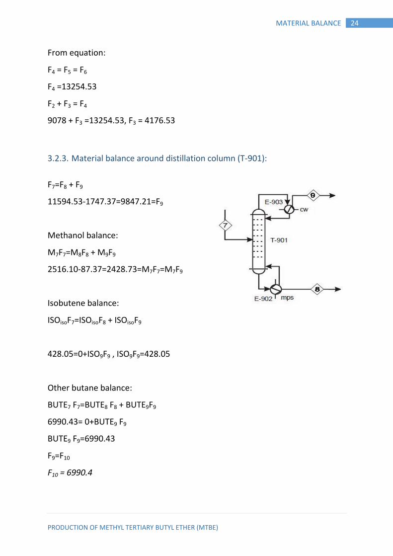
3.2.3. Material balance around distillation column (T-901):
F7=F8 + F9
11594.53-1747.37=9847.21=F9
Methanol balance:
M7F7=M8F8 + M9F9
2516.10-87.37=2428.73=M7F7=M7F9
Isobutene balance:
ISOisoF7=ISOisoF8 + ISOisoF9
428.05=0+ISO9F9 , ISO9F9=428.05
Other butane balance:
BUTE7 F7=BUTE8 F8 + BUTE9F9
6990.43= 0+BUTE9 F9
BUTE9 F9=6990.43
F9=F10
F10 = 6990.4
PRODUCTION OF METHYL TERTIARY BUTYL ETHER (MTBE)
25 MATERIAL BALANCE
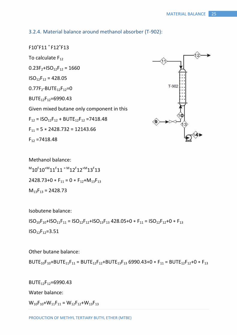
3.2.4. Material balance around methanol absorber (T-902):
F10+F11 = F12+F13
To calculate F12
0.23F2+ISO12F12 = 1660
ISO12F12 = 428.05
0.77F2-BUTE12F12=0
BUTE12F12=6990.43
Given mixed butane only component in this
F12 = ISO12F12 + BUTE12F12 =7418.48
F11 = 5 ∗ 2428.732 = 12143.66
F12 =7418.48
Methanol balance:
M10F10+M11F11 = M12F12+M13F13
2428.73+0 ∗ F11 = 0 ∗ F12+M13F13
M13F13 = 2428.73
Isobutene balance:
ISO10F10+ISO11F11 = ISO12F12+ISO13F13 428.05+0 ∗ F11 = ISO12F12+0 ∗ F13
ISO12F12=3.51
Other butane balance:
BUTE10F10+BUTE11F11 = BUTE12F12+BUTE13F13 6990.43+0 ∗ F11 = BUTE12F12+0 ∗ F13
BUTE12F12=6990.43
Water balance:
W10F10+W11F11 = W12F12+W13F13
PRODUCTION OF METHYL TERTIARY BUTYL ETHER (MTBE)
26 MATERIAL BALANCE
0 ∗ F10+1 ∗ F11 = 0 ∗ F12+W12 ∗ 14572.39
W13F13=12143.66
F13=F14
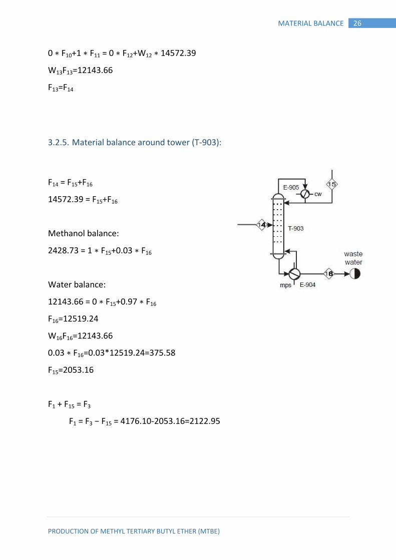
3.2.5. Material balance around tower (T-903):
F14 = F15+F16
14572.39 = F15+F16
Methanol balance:
2428.73 = 1 ∗ F15+0.03 ∗ F16
Water balance:
12143.66 = 0 ∗ F15+0.97 ∗ F16
F16=12519.24
W16F16=12143.66
0.03 ∗ F16=0.03*12519.24=375.58
F15=2053.16
F1 + F15 = F3
F1 = F3 − F15 = 4176.10-2053.16=2122.95
PRODUCTION OF METHYL TERTIARY BUTYL ETHER (MTBE)
27 MATERIAL BALANCE
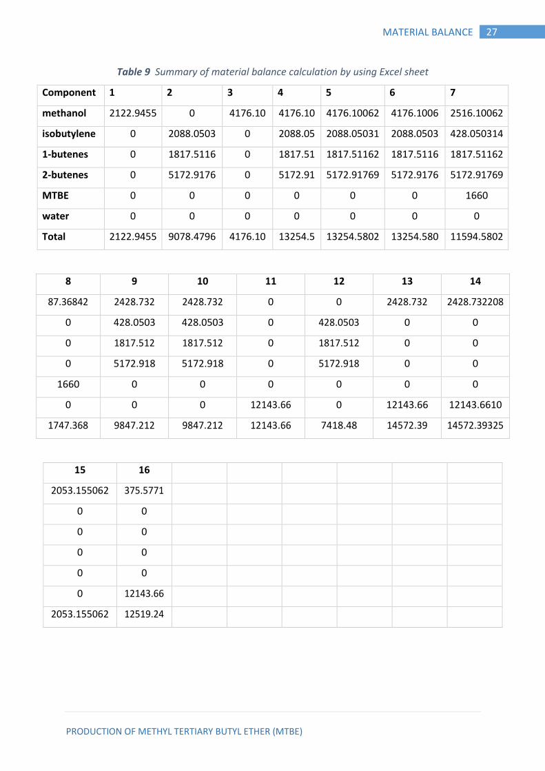
Table 9 Summary of material balance calculation by using Excel sheet
Component 1 2 3 4 5 6 7
methanol 2122.9455 0 4176.10 4176.10 4176.10062 4176.1006 2516.10062
isobutylene 0 2088.0503 0 2088.05 2088.05031 2088.0503 428.050314
1-butenes 0 1817.5116 0 1817.51 1817.51162 1817.5116 1817.51162
2-butenes 0 5172.9176 0 5172.91 5172.91769 5172.9176 5172.91769
MTBE 0 0 0 0 0 0 1660
water 0 0 0 0 0 0 0
Total 2122.9455 9078.4796 4176.10 13254.5 13254.5802 13254.580 11594.5802
8 9 10 11 12 13 14
87.36842 2428.732 2428.732 0 0 2428.732 2428.732208
0 428.0503 428.0503 0 428.0503 0 0
0 1817.512 1817.512 0 1817.512 0 0
0 5172.918 5172.918 0 5172.918 0 0
1660 0 0 0 0 0 0
0 0 0 12143.66 0 12143.66 12143.6610
1747.368 9847.212 9847.212 12143.66 7418.48 14572.39 14572.39325
15 16
2053.155062 375.5771
0 0
0 0
0 0
0 0
0 12143.66
2053.155062 12519.24
PRODUCTION OF METHYL TERTIARY BUTYL ETHER (MTBE)
28 ENERGY BALANCE
CHAPTER FOUR 4. ENERGY BALANCE
Introduction: 4.1.
As with mass, energy can be considered to be separately conserved in all but
nuclear process. The conservation of energy, however, differ from that of mass
in that energy can be generated (or consumed) in a chemical process. The
Total enthalpy of the outlet streams will not be equal that of the inlet streams
if energy is generated or consumed in the processes; such as that due to heat
of reaction.
In process design, energy balance is made to determine the energy
requirements of the process: the heating, cooling and power required. Inplant
operation, an energy balance on the plant operation will show the pattern of
energy usage and suggest areas for conservation and savings (Himmelblau &
Riggs, 2004).
Conservation of energy: 4.2.
The general equation can be written for conservation of energy is:
Energy out = Energy in – Generation – Consumption – Accumulation.
This is a statement of the first law of thermodynamics.
Chemical reaction will evolve energy (exothermic) or consume energy
(endothermic).For steady
State process the accumulation of both mass and energy will be zero.
PRODUCTION OF METHYL TERTIARY BUTYL ETHER (MTBE)
29 ENERGY BALANCE
Energy balance calculations: 4.3.
Symbols used in this chapter:
Cpi = Heat capacity of component (i).
T = Temperature of stream in degree Kelvin.
Mij = Mole flow of component (i) in stream (j).
Hj = Total enthalpy of stream (j).
Hij = enthalpy of component (i) in stream (j).
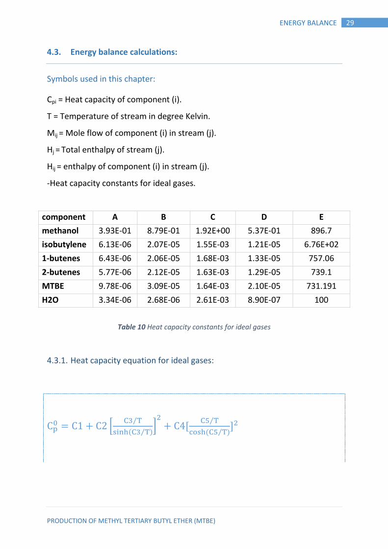
-Heat capacity constants for ideal gases.
component A B C D E
methanol 3.93E-01 8.79E-01 1.92E+00 5.37E-01 896.7
isobutylene 6.13E-06 2.07E-05 1.55E-03 1.21E-05 6.76E+02
1-butenes 6.43E-06 2.06E-05 1.68E-03 1.33E-05 757.06
2-butenes 5.77E-06 2.12E-05 1.63E-03 1.29E-05 739.1
MTBE 9.78E-06 3.09E-05 1.64E-03 2.10E-05 731.191
H2O 3.34E-06 2.68E-06 2.61E-03 8.90E-07 100
Table 10 Heat capacity constants for ideal gases
4.3.1. Heat capacity equation for ideal gases:
C C C *
⁄
( ⁄ )+
C ⁄
( ⁄ )
PRODUCTION OF METHYL TERTIARY BUTYL ETHER (MTBE)
30 ENERGY BALANCE
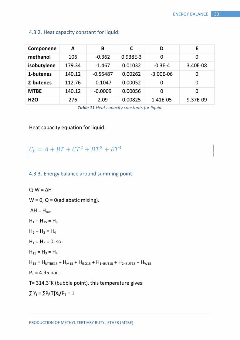
4.3.2. Heat capacity constant for liquid:
Componene
t
A B C D E
methanol 106 -0.362 0.938E-3 0 0
isobutylene 179.34 -1.467 0.01032
3
-0.3E-4 3.40E-08
1-butenes 140.12 -0.55487 0.00262
42
-3.00E-06 0
2-butenes 112.76 -0.1047 0.00052
1
0 0
MTBE 140.12 -0.0009 0.00056
3
0 0
H2O 276 2.09 0.00825 1.41E-05 9.37E-09
Table 11 Heat capacity constants for liquid.
Heat capacity equation for liquid:
4.3.3. Energy balance around summing point:
Q-W = ∆H
W = 0, Q = 0(adiabatic mixing).
∆H = Hout
H1 + H15 = H3
H2 + H3 = H4
H1 = H2 = 0; so:
H15 = H3 = H4
H15 = HMTBE15 + HM15 + HISO15 + H1−BUT15 + H2−BUT15 − HW15
PT = 4.95 bar.
T= 314.3°K (bubble point), this temperature gives:
∑ Yi = ∑Pi(T)Xi/PT = 1
PRODUCTION OF METHYL TERTIARY BUTYL ETHER (MTBE)
31 ENERGY BALANCE
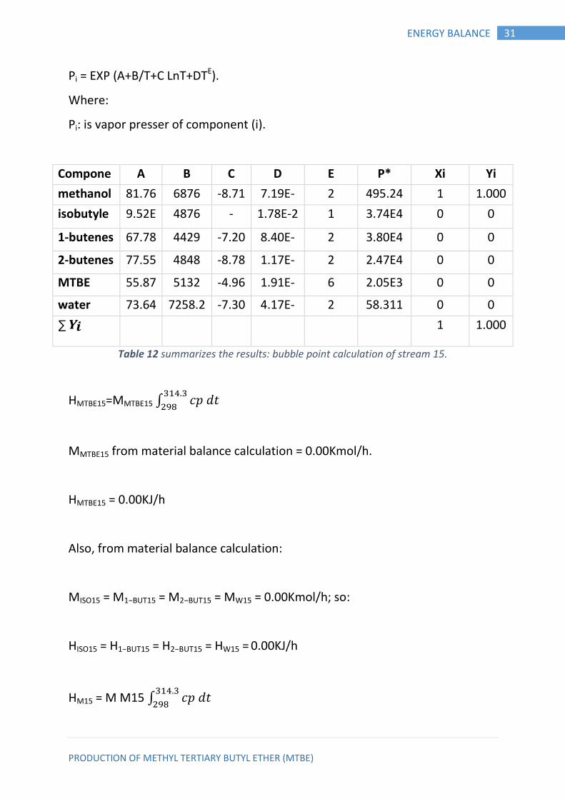
Pi = EXP (A+B/T+C LnT+DTE).
Where:
Pi: is vapor presser of component (i).
Compone
nt
A B C D E P* Xi Yi
methanol 81.76
8
6876 -8.71 7.19E-
06
2 495.24
72
1 1.000
2 isobutyle
ne
9.52E 4876 -
12.6
1.78E-2 1 3.74E4 0 0
1-butenes 67.78 4429 -7.20 8.40E-
06
2 3.80E4 0 0
2-butenes 77.55
1
4848 -8.78 1.17E-
05
2 2.47E4 0 0
MTBE 55.87
5
5132 -4.96 1.91E-
17
6 2.05E3 0 0
water 73.64
9
7258.2 -7.30 4.17E-
06
2 58.311
0
0 0
∑ 𝒀𝒊 1 1.000
Table 12 summarizes the results: bubble point calculation of stream 15.
HMTBE15=MMTBE15 ∫ 𝑝 𝑡
MMTBE15 from material balance calculation = 0.00Kmol/h.
HMTBE15 = 0.00KJ/h
Also, from material balance calculation:
MISO15 = M1−BUT15 = M2−BUT15 = MW15 = 0.00Kmol/h; so:
HISO15 = H1−BUT15 = H2−BUT15 = HW15 = 0.00KJ/h
HM15 = M M15 ∫ 𝑝 𝑡
PRODUCTION OF METHYL TERTIARY BUTYL ETHER (MTBE)
32 ENERGY BALANCE
MM15 from material balance calculation=2053.16Kmol/h.
HM15= 2053.16*[106(314.3-298) - 0.362/2(314.32-2982) +0.938E-3/3(314.33-
2983)]
HM15= 2781433.8KJ/h.
H4 = H5 (No change in enthalpy through the pump)
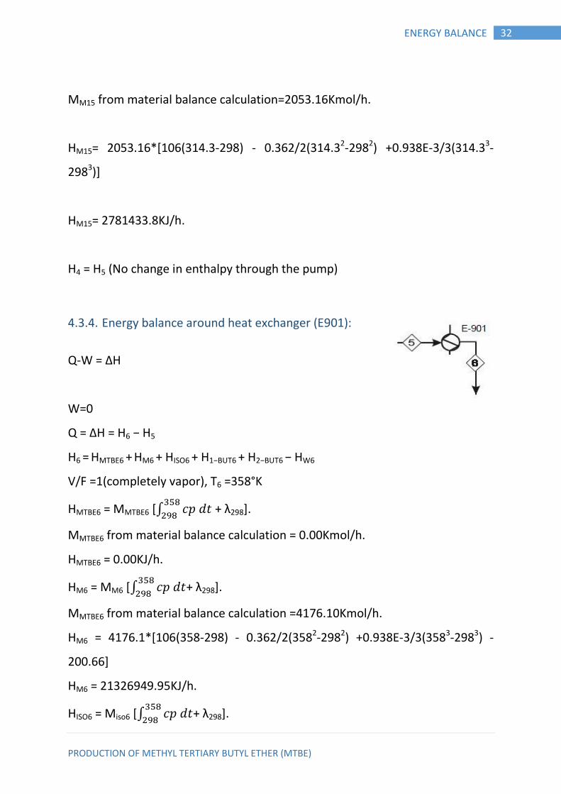
4.3.4. Energy balance around heat exchanger (E901):
Q-W = ∆H
W=0
Q = ∆H = H6 − H5
H6 = HMTBE6 + HM6 + HISO6 + H1−BUT6 + H2−BUT6 − HW6
V/F =1(completely vapor), T6 =358°K
HMTBE6 = MMTBE6 [∫ 𝑝 𝑡
+ λ298].
MMTBE6 from material balance calculation = 0.00Kmol/h.
HMTBE6 = 0.00KJ/h.
HM6 = MM6 [∫ 𝑝 𝑡
+ λ298].
MMTBE6 from material balance calculation =4176.10Kmol/h.
HM6 = 4176.1*[106(358-298) - 0.362/2(3582-2982) +0.938E-3/3(3583-2983) -
200.66]
HM6 = 21326949.95KJ/h.
HISO6 = Miso6 [∫ 𝑝 𝑡
+ λ298].
PRODUCTION OF METHYL TERTIARY BUTYL ETHER (MTBE)
33 ENERGY BALANCE
Miso6 from material balance calculation =2088.05Kmol/h.
HISO6 = 2088.05*[179.34 (358-298) - 1.467/2(3582-2982) +0.010323/3(3583-
2983)
-0.3E-4/4(3584-2984) +3.40E-08/5(3585-2985)-16.9059].
HISO6 = 17992470.95KJ/h.
H1−but6 = M1−but6 [∫ 𝑝 𝑡
+ λ298].
M1−but6 from material balance calculation =1817.511622Kmol/h.
H1−but6 = 1817.511622*[140.12 (358-298) - 0.55487/2(3582-2982) +0.26242E-
2/3(3583-2983) -3.00E-06/4(3584-2984) -0.53974].
H1−but6 = 14664582.86KJ/h.
H2−but6 = M2−but6 [∫ 𝑝 𝑡
+ λ298].
M2−but6 from material balance calculation =5172.917692Kmol/h.
H2−but6 = 5172.917692*[112.76 (358-298) -0.1047 /2(3582-2982) +0.521E-3
/3(3583-2983)-8.78031]
H2−but6 = 41739225.95KJ/h.
H6 = 21326949.95 + 17992470.95 + 14664582.86 + 41739225.95
H6 = 95723229.71KJ/h.
Q =m*λsteam
Q = 114767838.5
m = 114767838.5 *18/36098.259 = 57227.7Kg/h.

PRODUCTION OF METHYL TERTIARY BUTYL ETHER (MTBE)
34 ENERGY BALANCE
4.3.5. Energy balance around reactor (R901):
The conversion in the reactor is 80% and the reactor is adiabatic. So we
calculate the adiabatic temperature (T7) from equation below.
Conversion(x) =
∑ ∫
Where:
θi = ratio of component(i)in the feed to reference component(isobutylene
feed).
Compone
nt
𝛉𝐢
methanol 2.00
isobutyle
ne
1.00
1-butenes 0.87
2-butenes 2.48
MTBE 0.00
water 0.00
∆HR = heat of reaction at the adiabatic temperature (T7):
∆HR(T7) = ∆H°R+∫
∆H°R = HMTB6 − HM − HISO
∆H°R = -2.80E+04 KJ/Kmol.
∫
= ∫ 𝑛
(cpMTB6 − cpM − cpISO) dt. Solving for T7 by trial and error,
By using excel sheet:
T7 = 403°K.
H7 = HMTBE7 + HM7 + HISO7 + H1−BUT7 + H2−BUT7 − HW7
Table 13 Ratio of component (i) in the feed to isobutylene feed.

PRODUCTION OF METHYL TERTIARY BUTYL ETHER (MTBE)
35 ENERGY BALANCE
HMTBE7 = MMTBE7 ∫
+ λ298].
MMTBE7 from material balance caculation = 1660Kmol/h.
HMTBE7 =1660*[140.12 (403-298)-0.9E-3/2(4032-2982) +0.563E-3/3(4033-2983)-
283.4992].
HMTBE7 = 16066714.2KJ/h.
HM7 = MM7 [∫
+ λ298].
MM7 from material balance calculation =2516.10Kmol/h.
HM7 = 2516.1*[106(304-298) - 0.362/2(4032-2982) +0.938E-3/3(4033-2983) -
200.66].
HM7 = 11295476.78KJ/h.
HISO7 = Miso7 ∫
+λ298].
Miso7 from material balance calculation = 428.05Kmol/h.
HISO6 =428.05*[179.34 (403-298) - 1.467/2(4032-2982) +0.010323/3(4033-2983) -
0.3E-4/4(4034-2984) +3.40E-08/5(4035-2985)-16.9059].
HISO6 = 3375687.845KJ/h.
H1−but7 = M1−but7 [∫
λ298]
M1−but7 from material balance calculation =1817.511622Kmol/h.
H1−but7 = 1817.511622*[140.12 (403-298) - 0.55487/2(4032-2982) +0.26242E-
2/3(4033-2983) -3.00E-06/4(4304-2984) -0.53974].
H1−but7 = 11737411.97KJ/h.
H2−but7 = M2−but7[ ∫
λ298].
PRODUCTION OF METHYL TERTIARY BUTYL ETHER (MTBE)
36 ENERGY BALANCE
M2−but7 from material balance calculation =5172.917692Kmol/h.
H2−but7 = 5172.917692*[112.76(403-298) -0.1047 /2(4032-2982) +0.521E-3
/3(4033-2983)-8.78031]
H2−but7 = 34508550.26KJ/h.
H7 = 1.4672E11KJ/h.
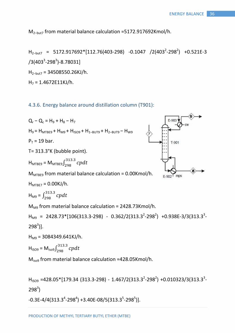
4.3.6. Energy balance around distillation column (T901):
Qr − Qc = H9 + H8 − H7
H9 = HMTBE9 + HM9 + HISO9 + H1−BUT9 + H2−BUT9 − HW9
PT = 19 bar.
T= 313.3°K (bubble point).
HMTBE9 = MMTBE9∫ 𝑝 𝑡
MMTBE9 from material balance calculation = 0.00Kmol/h.
HMTBE7 = 0.00KJ/h.
HM9 = ∫ 𝑝 𝑡
MM9 from material balance calculation = 2428.73Kmol/h.
HM9 = 2428.73*[106(313.3-298) - 0.362/2(313.32-2982) +0.938E-3/3(313.33-
2983)].
HM9 = 3084349.641KJ/h.
HISO9 = Miso9∫ 𝑝 𝑡
Miso9 from material balance calculation =428.05Kmol/h.
HISO9 =428.05*[179.34 (313.3-298) - 1.467/2(313.32-2982) +0.010323/3(313.33-
2983)
-0.3E-4/4(313.34-2984) +3.40E-08/5(313.35-2985)].
PRODUCTION OF METHYL TERTIARY BUTYL ETHER (MTBE)
37 ENERGY BALANCE
HISO9 = 8.84E5KJ/h.
H1−but9 = M1−but9 ∫ 𝑝 𝑡
M1−but9 from material balance calculation =1817.511622Kmol/h.
H1−but9 = 1817.511622*[140.12 (313.3-298) - 0.55487/2(313.32-2982)
+0.26242E-2/3(313.33-2983) -3.00E-06/4(313.34-2984)].
H1−but9 = 3615478.074KJ/h.
H2−but9 = M2−but9 ∫ 𝑝 𝑡
M2−but9 from material balance calculation =5172.917692Kmol/h.
H2−but9 = 5172.917692*[112.76(313.3-298) -0.1047 /2(313.32-2982) +0.521E-3
/3(313.33-
2983)].
H2−but9 = 10244724.91KJ/h. H9 = 17829041.27KJ/h.
Condenser duty calculation:
Vapor temp. = 319.8°K(dew point).
Qc = (1 + R)(HV9 − H9).
R = 1.8
HV9Can be calculated by using heat capacity constants for ideal gases, with the
fallowing equation:
HiV9 = Mi9 [∫ 𝑝 𝑡
+ λ298].
PRODUCTION OF METHYL TERTIARY BUTYL ETHER (MTBE)
38 ENERGY BALANCE
→ HV9 = 18886227.06KJ/h.
∴ Qc = 2.8(18886227.06 − 17829041.27)
Qc = 2960120.19KJ/h.
-Amount of cooling water:
M
∗ =
( ) = 70816.27kg/h.
H8 = HMTBE8 + HM8 + HISO8 + H1−BUT8 + H2−BUT8 − HW8
HMTBE8 = MMTBE8 ∫ 𝑝 𝑡
MMTBE8 from material balance calculation = 1660Kmol/h.
HMTBE8 = 1660*[140.12 (314.74-298)-0.9E-3/2(314.742-2982) +0.563E-
3/3(314.743-2983)].
HMTBE8 = 5356128.348KJ/h.
HM8 = MM8 ∫ 𝑝 𝑡
MM8 from material balance calculation = 87.37Kmol/h.
HM8 = 87.37*[106(314.74-298) - 0.362/2(314.742-2982) +0.938E-3/3(314.743-
2983)].
HM8 = 121652.5772KJ/h.
From material balance calculation:
MISO8 = M1−BUT8 = M2−BUT8 = MW8 = 0.00Kmol/h; so:
HISO8 = H1−BUT8 = H2−BUT8 = HW8 = 0.00KJ/h.
∴ H8 = 5477780.925KJ/h.
Reboiler duty calculation:
PRODUCTION OF METHYL TERTIARY BUTYL ETHER (MTBE)
39 ENERGY BALANCE
Qr = Qc + H9 + H8 − H7
Qr = 258116146.6KJ/h.
-Amount of stream needed:
M
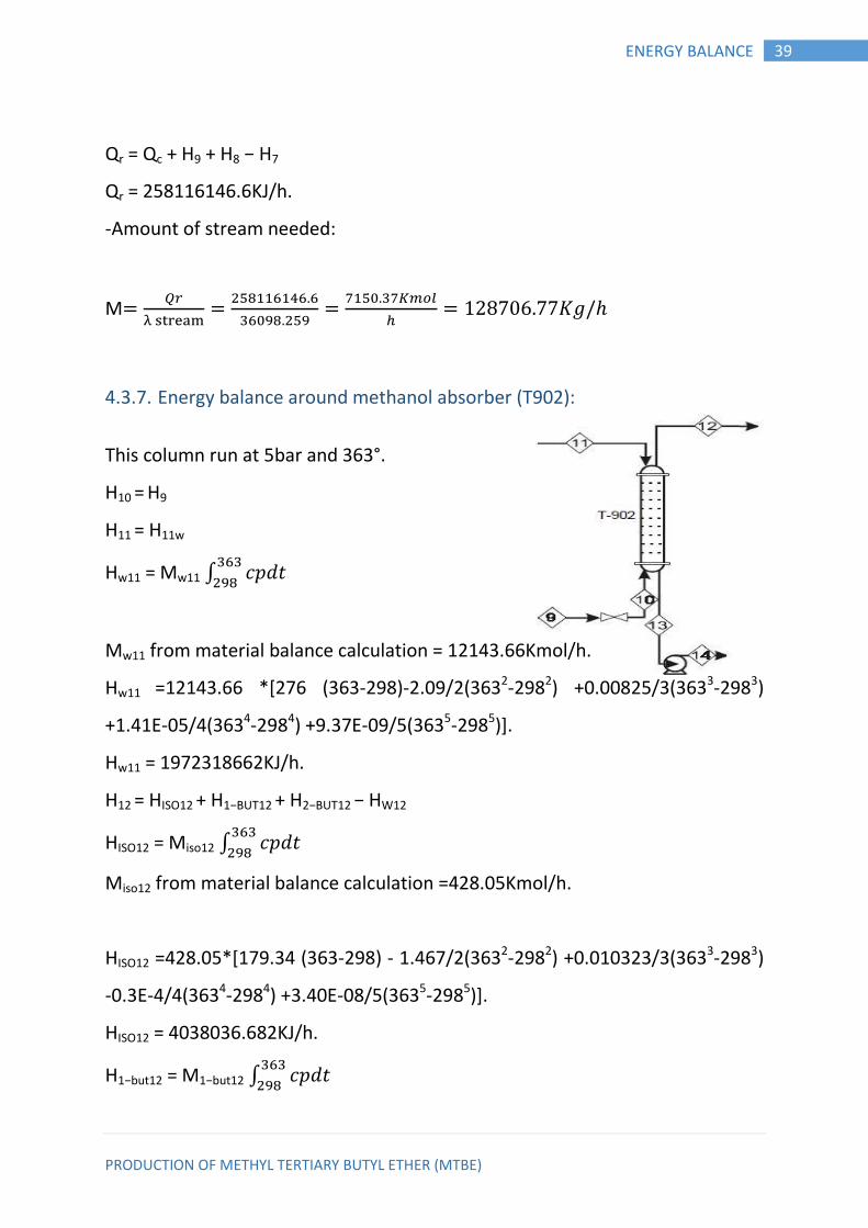
4.3.7. Energy balance around methanol absorber (T902):
This column run at 5bar and 363°.
H10 = H9
H11 = H11w
Hw11 = Mw11 ∫ 𝑝 𝑡
Mw11 from material balance calculation = 12143.66Kmol/h.
Hw11 =12143.66 *[276 (363-298)-2.09/2(3632-2982) +0.00825/3(3633-2983)
+1.41E-05/4(3634-2984) +9.37E-09/5(3635-2985)].
Hw11 = 1972318662KJ/h.
H12 = HISO12 + H1−BUT12 + H2−BUT12 − HW12
HISO12 = Miso12 ∫ 𝑝 𝑡
Miso12 from material balance calculation =428.05Kmol/h.
HISO12 =428.05*[179.34 (363-298) - 1.467/2(3632-2982) +0.010323/3(3633-2983)
-0.3E-4/4(3634-2984) +3.40E-08/5(3635-2985)].
HISO12 = 4038036.682KJ/h.
H1−but12 = M1−but12 ∫ 𝑝 𝑡

PRODUCTION OF METHYL TERTIARY BUTYL ETHER (MTBE)
40 ENERGY BALANCE
M1−but12 from material balance calculation =1817.511622Kmol/h.
H1−but12 = 1817.511622*[140.12 (363-298) - 0.55487/2(3632-2982) +0.26242E-
2/3(3633-2983) -3.00E-06/4(3634-2984)].
H1−but12 = 15943036.3KJ/h.
H2−but12 = M2−but12∫ 𝑝 𝑡
M2−but12 from material balance calculation =5172.917692Kmol/h.
H2−but12 = 5172.917692*[112.76(363-298) -0.1047 /2(3632-2982) +0.521E-3
/3633-2983)].
H2−but12 = 45476091.78KJ/h.
H12 = 4038036.682 + 159
43036.3 + 45476091.78
H12 = 65457164.76KJ/h.
H13 = HM13 + Hw13
HM13 = MM13 ∫ 𝑝 𝑡
MM13 from material balance calculation = 2428.73Kmol/h.
HM13 = 2428.73*[106(363-298) - 0.362/2(3632-2982) +0.938E-3/3(3633-2983)].
HM13 = 14073458.46KJ/h.
Hw13 = Mw13 ∫ 𝑝 𝑡
Mw13 from material balance calculation = 12143.66Kmol/h.
Hw13 = 12143.66 *[276 (363-298) -2.09/2(3632-2982) +0.00825/3(3633-2983)
+1.41E-05/4(3634-2984) +9.37E-09/5(3635-2985)].
Hw13 = 1972318662KJ/h.
H13 = 14073458.46 + 1972318662
PRODUCTION OF METHYL TERTIARY BUTYL ETHER (MTBE)
41 ENERGY BALANCE
H13 = 1972318662KJ/h.
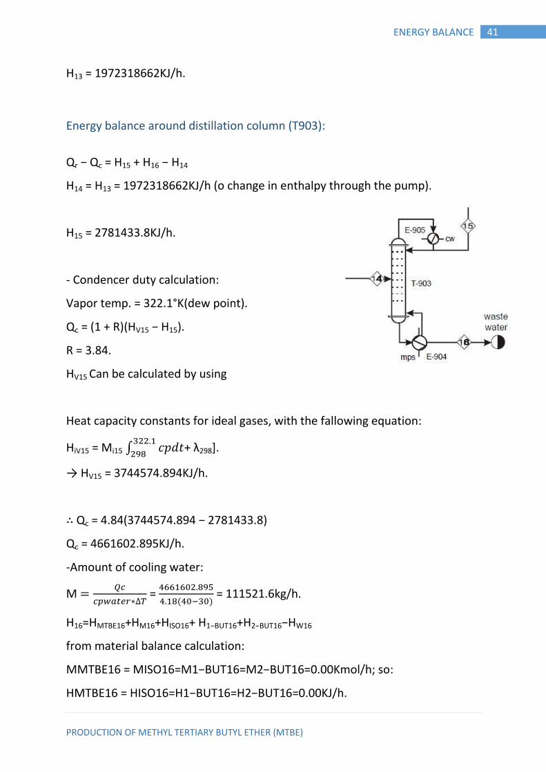
Energy balance around distillation column (T903):
Qr − Qc = H15 + H16 − H14
H14 = H13 = 1972318662KJ/h (o change in enthalpy through the pump).
H15 = 2781433.8KJ/h.
- Condencer duty calculation:
Vapor temp. = 322.1°K(dew point).
Qc = (1 + R)(HV15 − H15).
R = 3.84.
HV15 Can be calculated by using
Heat capacity constants for ideal gases, with the fallowing equation:
HiV15 = Mi15 ∫ 𝑝 𝑡
+ λ298].
→ HV15 = 3744574.894KJ/h.
∴ Qc = 4.84(3744574.894 − 2781433.8)
Qc = 4661602.895KJ/h.
-Amount of cooling water:
M
∗ =
( ) = 111521.6kg/h.
H16=HMTBE16+HM16+HISO16+ H1−BUT16+H2−BUT16−HW16
from material balance calculation:
MMTBE16 = MISO16=M1−BUT16=M2−BUT16=0.00Kmol/h; so:
HMTBE16 = HISO16=H1−BUT16=H2−BUT16=0.00KJ/h.
PRODUCTION OF METHYL TERTIARY BUTYL ETHER (MTBE)
42 ENERGY BALANCE
H16=Hw16+HM16
HM16= MM16∫ 𝑝 𝑡
MM16 from material balance calculation=375.58Kmol/h.
HM16= 375.58*[106(430.2-298) - 0.362/2(v2-2982) +0.938E-3/3(430.23-
2983)].
HM16=16824464.12KJ/h.
Hw16= Mw16∫ 𝑝 𝑡
Mw16 from material balance calculation=12143.66Kmol/h.
Hw16=12143.66 *[276 (430.2-298) -2.09/2(430.22-2982) +0.00825/3(430.23-
2983) +1.41E-
05/4(430.24-2984) +9.37E-09/5(430.25-2985)].
Hw16 = 5849089008KJ/h.
H16 = 16824464.12 + 5849089008
H16 = 5865913472KJ/h.
Reboiler duty calculation:
Qr − Qc = H15 + H16 − H14
Qr = 48907569980KJ/h.
-Amount of stream needed:
M
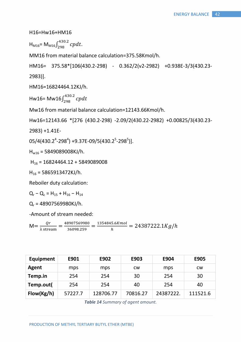
Equipment E901 E902 E903 E904 E905
Agent mps mps cw mps cw
Temp.in
(℃)
254 254 30 254 30
Temp.out(
℃)
254 254 40 254 40
Flow(Kg/h) 57227.7 128706.77 70816.27 24387222.
1
111521.6
Table 14 Summary of agent amount.
PRODUCTION OF METHYL TERTIARY BUTYL ETHER (MTBE)
43 ENERGY BALANCE
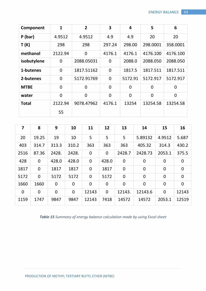
Component 1 2 3 4 5 6
P (bar) 4.9512 4.9512 4.9 4.9 20 20
T (K) 298 298 297.24 298.00 298.0001 358.0001
methanol 2122.94
556
0 4176.1 4176.1 4176.100 4176.100
isobutylene 0 2088.05031 0 2088.0 2088.050 2088.050
1-butenes 0 1817.51162 0 1817.5 1817.511 1817.511
2-butenes 0 5172.91769
2
0 5172.91
8
5172.917
692
5172.917
692 MTBE 0 0 0 0 0 0
water 0 0 0 0 0 0
Total 2122.94
55
9078.47962 4176.1 13254 13254.58 13254.58
Table 15 Summary of energy balance calculation made by using Excel sheet
7 8 9 10 11 12 13 14 15 16
20 19.25 19 10 5 5 5 5.89132 4.9512 5.687
403 314.7
43
8
313.3 310.2 363 363 363 405.32 314.3 430.2
2516 87.36
84
2
2428.
73
2
2428.
73
2
0 0 2428.7
3
2
2428.73
220
8
2053.1
5506
2
375.5
77
1
428 0 428.0
50
3
428.0
50
3
0 428.0
50
3
0 0 0 0
1817 0 1817
2
1817
2
0 1817
2
0 0 0 0
5172 0 5172 5172 0 5172 0 0 0 0
1660 1660 0 0 0 0 0 0 0 0
0 0 0 0 12143
.6
6
0 12143.
6
6
12143.6
610
4
0 12143
.6
6
1159
4.58
1747 9847 9847 12143 7418 14572 14572 2053.1
55
12519
4
PRODUCTION OF METHYL TERTIARY BUTYL ETHER (MTBE)
44 CONCLUSION & RECOMMENDATIONS
CHAPTER FIVE 5. DESIGN
Distillation design: 5.1.
5.1.1. Introduction:
Distillation is most common class of separation processes and properly of the
better-understand unit operation that uses the difference in relative volatilities
, or differences in boiling of the component to be separated, it is the most
widely used method of separation in the process industries
Types of distillation column:
Single flash vaporization.
Packed towers.
Plates towers.
a) Bubble cap towers.
b) Sieve pates.
c) Valve plates towers.
Sieve trays: Sieve trays offer several advantage over bubble-cap trays, and
their simpler and cheaper construction has led to their increasing use. The
general form of the flow on a sieve tray is typical of a cross flow system with
perforation in the tray taking the place of the more complex bubble caps. The
key differences in operation between these two types of tray should be noted.
With the sieve tray the vapor passes vertically through the holes into the liquid
on the tray, whereas with the bubble cap the vapor issues in an approximately
PRODUCTION OF METHYL TERTIARY BUTYL ETHER (MTBE)
45 CONCLUSION & RECOMMENDATIONS
horizontal direction from the slots . With the sieve plate the vapor velocity
through the perforation must be greater than a certain minimum value in
order to prevent the weeping of the liquid stream down through the holes. At
the other extreme, a very high vapor velocity leads to excessive entrainment
and loss off tray efficiency.
5.1.2. Collect the data of fluid to be distillated and distillated
Fluids:
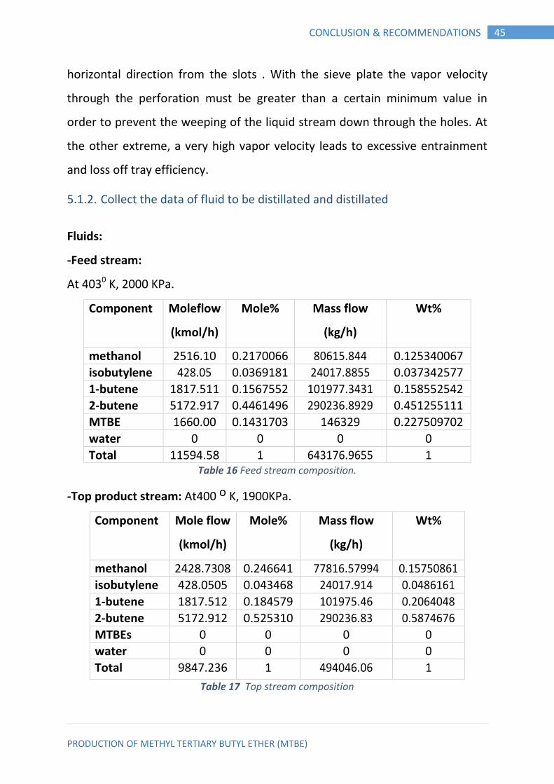
-Feed stream:
At 4030 K, 2000 KPa.
Component Moleflow
(kmol/h)
Mole% Mass flow
(kg/h)
Wt%
methanol 2516.10 0.2170066
16
80615.844 0.125340067
isobutylene 428.05 0.0369181
38
24017.8855 0.037342577
1-butene 1817.511
622
0.1567552
75
101977.3431 0.158552542
2-butene 5172.917
692
0.4461496
3
290236.8929 0.451255111
MTBE 1660.00 0.1431703
4
146329 0.227509702
water 0 0 0 0
Total 11594.58 1 643176.9655 1 Table 16 Feed stream composition.
-Top product stream: At400 o K, 1900KPa.
Component Mole flow
(kmol/h)
Mole% Mass flow
(kg/h)
Wt%
methanol 2428.7308 0.246641
613
77816.57994 0.15750861
5 isobutylene 428.0505 0.043468
9
24017.914 0.0486161
1-butene 1817.512 0.184579
2
101975.46 0.2064048
2-butene 5172.912 0.525310
7
290236.83 0.5874676
MTBEs 0 0 0 0
water 0 0 0 0
Total 9847.236 1 494046.06 1
Table 17 Top stream composition
PRODUCTION OF METHYL TERTIARY BUTYL ETHER (MTBE)
46 CONCLUSION & RECOMMENDATIONS
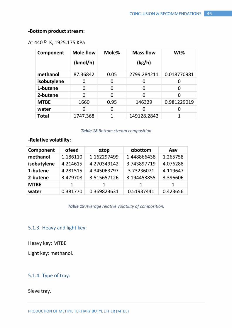
-Bottom product stream:
At 440 o K, 1925.175 KPa
Component Mole flow
(kmol/h)
Mole% Mass flow
(kg/h)
Wt%
methanol 87.36842
105
0.05 2799.284211 0.018770981
isobutylene 0 0 0 0
1-butene 0 0 0 0
2-butene 0 0 0 0
MTBE 1660 0.95 146329 0.981229019
water 0 0 0 0
Total 1747.368
421
1 149128.2842 1
Table 18 Bottom stream composition
-Relative volatility:
Component αfeed αtop αbottom Αav methanol 1.186110
097
1.162297499 1.448866438 1.265758
isobutylene 4.214615
978
4.270349142 3.743897719 4.076288
1-butene 4.281515
808
4.345063797 3.73236071 4.119647
2-butene 3.479708
054
3.515657126 3.194453855 3.396606
MTBE 1 1 1 1
water 0.381770
611
0.369823631 0.51937441 0.423656
Table 19 Average relative volatility of composition.
5.1.3. Heavy and light key:
Heavy key: MTBE
Light key: methanol.
5.1.4. Type of tray:
Sieve tray.

PRODUCTION OF METHYL TERTIARY BUTYL ETHER (MTBE)
47 CONCLUSION & RECOMMENDATIONS
5.1.5. Determination of minimum reflux ratio:
∑
𝑚 (1)
α= average Relative volatility of any component.
X= mole faction of component in Distillate.
Ø= Constant.
Rm = Minimum reflux ratio.
∑
𝑞 (2)
Where:
Zf= mole faction of component in feed stream.
q= feed quality
q=
HG=Enthalpy of gas at the feed dew point (KJ/Kmol)
HL=Enthalpy of liquid at the feed bubble point (KJ/Kmol)
HF=Enthalpy of feed at 403o K.
q=
=1.86
Substitute in equation (2) to find (Ø)
∑
=1-1.86
∑
-0.86
+
+
+
+
+
= 0
Solving Ø By try &error:
Ø =1.047365
Substitute in equation (1) to find Rm:
+
+
+

PRODUCTION OF METHYL TERTIARY BUTYL ETHER (MTBE)
48 CONCLUSION & RECOMMENDATIONS
+
+
= Rm+1
Rm= 1.494995
5.1.6. Calculation of the actual ratio(R)
The rule of thumb is:
R = (1.2 ------- 1.5) R min
R=1.2Rm
=1.2×1.5 = 1.8
5.1.7. Calculation of the minimum number of theoretical stages:
N L (
) ∗ (
)
L
𝑋𝑙𝑘=mole fraction of light key.
𝑋 𝑘= mole fraction of heavy key.
𝛼𝑙𝑘= average relative volatility of light key.
Nmin= 26 stagess
5.1.8. Calculation of the number of theoretical stages:
[ (
)
]
R R
R
From Gilland relation.
→ N=57.695 stages
PRODUCTION OF METHYL TERTIARY BUTYL ETHER (MTBE)
49 CONCLUSION & RECOMMENDATIONS
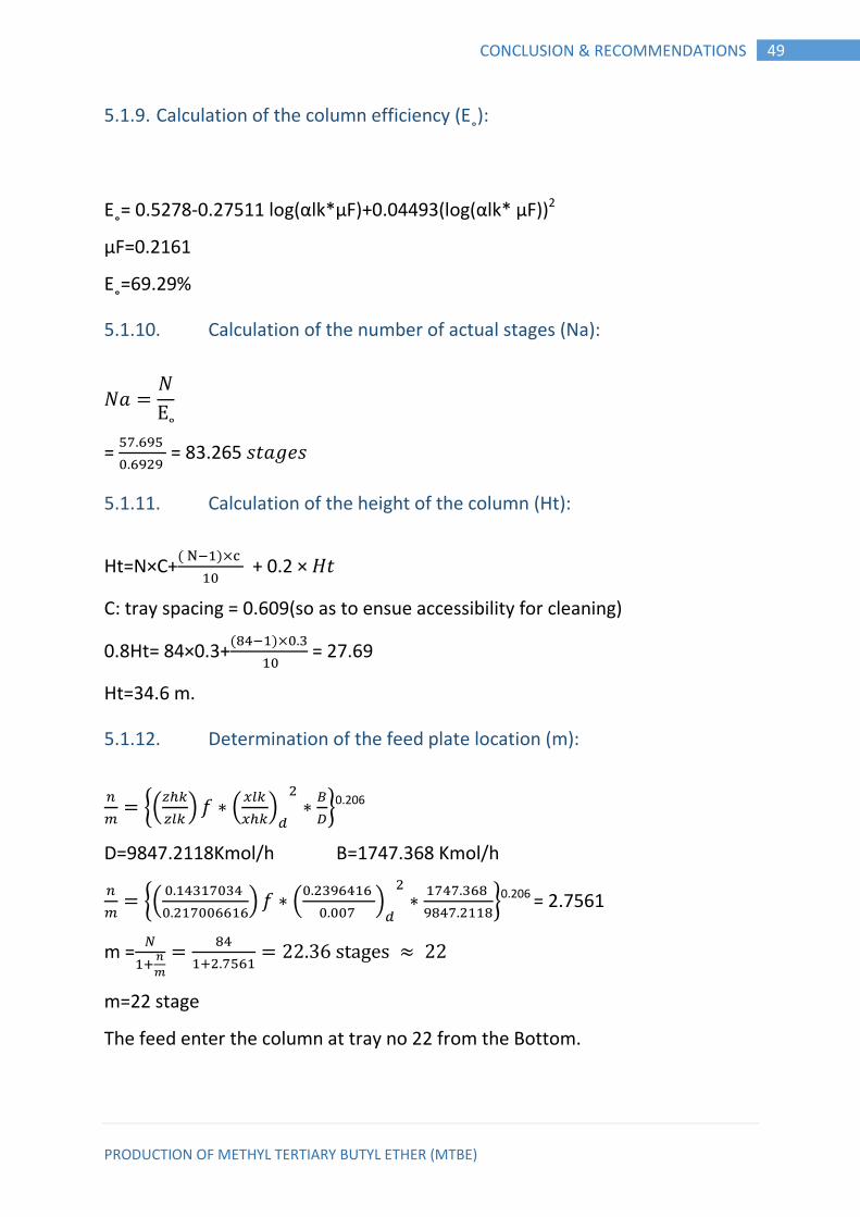
5.1.9. Calculation of the column efficiency (E˳):
E˳= 0.5278-0.27511 log(αlk*μF)+0.04493(log(αlk* μF))2
μF=0.2161
E˳=69.29%
5.1.10. Calculation of the number of actual stages (Na):
E
=
= 83.265 𝑠𝑡 𝑒𝑠
5.1.11. Calculation of the height of the column (Ht):
Ht=N×C+( )
+ 0.2 × 𝐻𝑡
C: tray spacing = 0.609(so as to ensue accessibility for cleaning)
0.8Ht= 84×0.3+( )
= 27.69
Ht=34.6 m.
5.1.12. Determination of the feed plate location (m):
{(
) ∗ (
)
∗
}0.206
D=9847.2118Kmol/h B=1747.368 Kmol/h
{(
) ∗ (
)
∗
}0.206 = 2.7561
m =
m=22 stage
The feed enter the column at tray no 22 from the Bottom.
PRODUCTION OF METHYL TERTIARY BUTYL ETHER (MTBE)
50 CONCLUSION & RECOMMENDATIONS
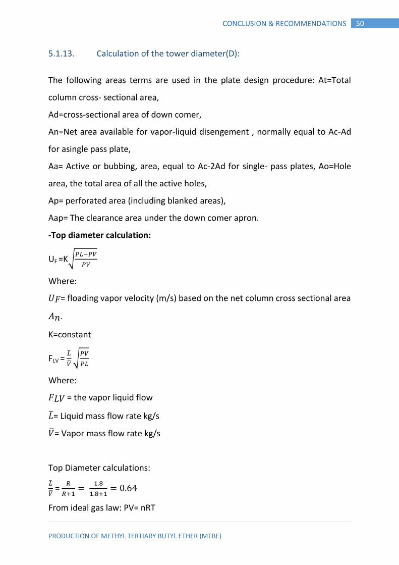
5.1.13. Calculation of the tower diameter(D):
The following areas terms are used in the plate design procedure: At=Total
column cross- sectional area,
Ad=cross-sectional area of down comer,
An=Net area available for vapor-liquid disengement , normally equal to Ac-Ad
for asingle pass plate,
Aa= Active or bubbing, area, equal to Ac-2Ad for single- pass plates, Ao=Hole
area, the total area of all the active holes,
Ap= perforated area (including blanked areas),
Aap= The clearance area under the down comer apron.
-Top diameter calculation:
UF =K√
Where:
𝑈𝐹= floading vapor velocity (m/s) based on the net column cross sectional area
𝑛.
K=constant
FLV =
√
Where:
𝐹𝐿𝑉 = the vapor liquid flow
��= Liquid mass flow rate kg/s
��= Vapor mass flow rate kg/s
Top Diameter calculations:
=
From ideal gas law: PV= nRT
PRODUCTION OF METHYL TERTIARY BUTYL ETHER (MTBE)
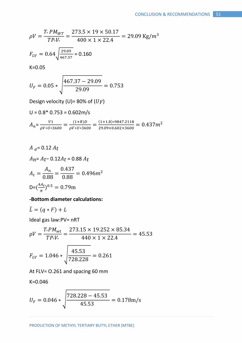
51 CONCLUSION & RECOMMENDATIONS
𝑉
𝑉
𝑚
𝐹 √
= 0.160
K=0.05
𝑈 ∗ √
Design velocity (U)= 80% of (𝑈𝐹)
U = 0.8* 0.753 = 0.602m/s
=
∗ ∗
( )
∗ ∗
( )∗
𝑚
= 0.12 𝑡
𝑛= 𝑡− 0.12 𝑡 = 0.88 𝑡
𝑚
D=(
)
-Bottom diameter calculations:
�� (𝑞 ∗ 𝐹) 𝐿
Ideal gas law:PV= nRT
𝑉
𝑉
𝐹 ∗ √
At FLV= O.261 and spacing 60 mm
K=0.046
𝑈 ∗ √
PRODUCTION OF METHYL TERTIARY BUTYL ETHER (MTBE)
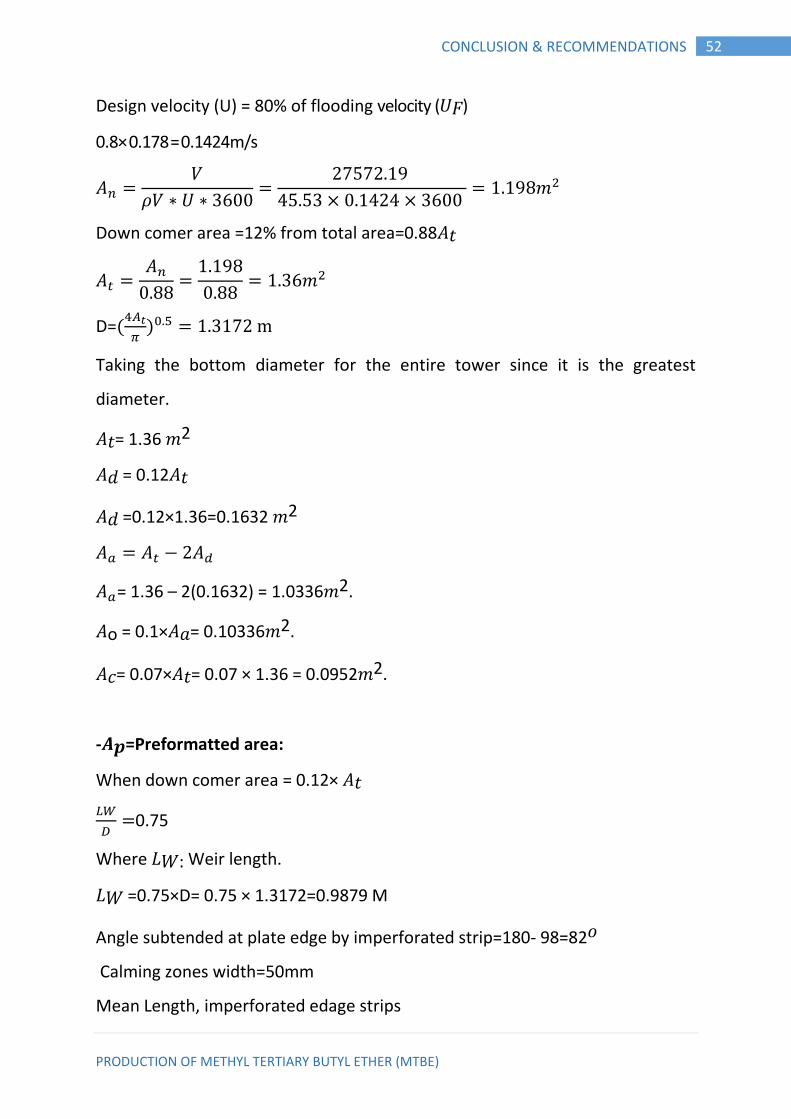
52 CONCLUSION & RECOMMENDATIONS
Design velocity (U) = 80% of flooding velocity (𝑈𝐹)
0.8× 0.178 = 0.1424m/s
𝑉
𝑉 ∗ 𝑈 ∗
𝑚
Down comer area =12% from total area=0.88 𝑡
𝑚
D=(
)
Taking the bottom diameter for the entire tower since it is the greatest
diameter.
𝑡= 1.36 𝑚2
= 0.12 𝑡
=0.12×1.36=0.1632 𝑚2
= 1.36 – 2(0.1632) = 1.0336𝑚2.
o = 0.1× = 0.10336𝑚2.
= 0.07× 𝑡= 0.07 × 1.36 = 0.0952𝑚2.
-𝑨𝒑=Preformatted area:
When down comer area = 0.12× 𝑡
0.75
Where 𝐿𝑊: Weir length.
𝐿𝑊 =0.75×D= 0.75 × 1.3172=0.9879 M
Angle subtended at plate edge by imperforated strip=180- 98=82𝑜
Calming zones width=50mm
Mean Length, imperforated edage strips
PRODUCTION OF METHYL TERTIARY BUTYL ETHER (MTBE)
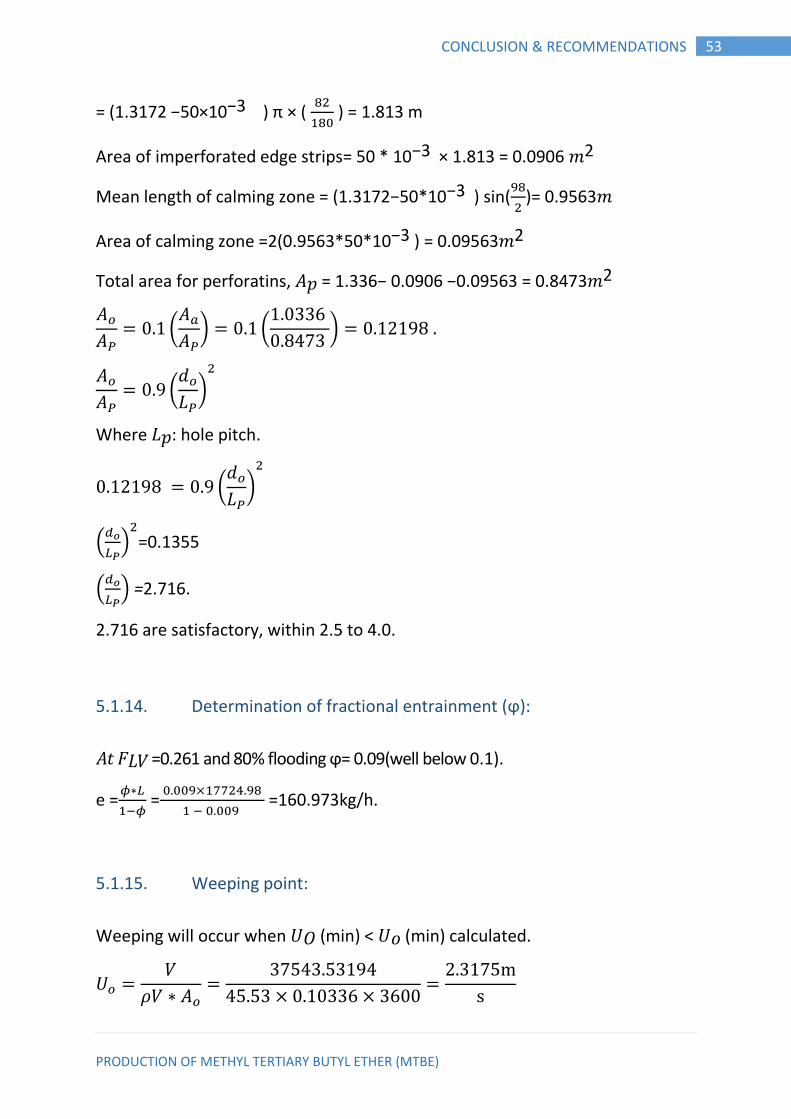
53 CONCLUSION & RECOMMENDATIONS
= (1.3172 −50×10−3 ) π × (
) = 1.813 m
Area of imperforated edge strips= 50 * 10−3 × 1.813 = 0.0906 𝑚2
Mean length of calming zone = (1.3172−50*10−3 ) sin(
)= 0.9563𝑚
Area of calming zone =2(0.9563*50*10−3 ) = 0.09563𝑚2
Total area for perforatins, 𝑝 = 1.336− 0.0906 −0.09563 = 0.8473𝑚2
(
) (
)
(
𝐿 )
Where 𝐿𝑝: hole pitch.
(
𝐿 )
(
)
=0.1355
(
) =2.716.
2.716 are satisfactory, within 2.5 to 4.0.
5.1.14. Determination of fractional entrainment (ϕ):
𝑡 𝐹𝐿𝑉 =0.261 and 80% flooding ϕ= 0.09(well below 0.1).
e = ∗
=
=160.973kg/h.
5.1.15. Weeping point:
Weeping will occur when 𝑈𝑂 (min) < 𝑈𝑜 (min) calculated.
𝑈 𝑉
𝑉 ∗
PRODUCTION OF METHYL TERTIARY BUTYL ETHER (MTBE)
54 CONCLUSION & RECOMMENDATIONS
Taking 70% turn down.
𝑈𝑜 (min) = 0.7×𝑈𝑜= 0.7 ×2.3175 = 1.624 m/s.
𝑈𝑂 (min) calculated = ( )
𝑜=5mm
𝑘2is a function of ( 𝑤 + 𝑜𝑤 (min))
𝑤: weir hight = 23 mm
𝑜𝑤 (min): minimum weir crest =750× (
)
𝐿𝑚𝑖𝑛= o.7×17724.98 = 12407.486kg/h.
(𝑚𝑖𝑛) ∗ (
)
⁄
𝑤+ 𝑜𝑤 (min)=23+21.31= 44.31mm.
𝑘2=30
𝑈𝑂 (min) calculated = ( )
( )
∴Weeping will not occur.
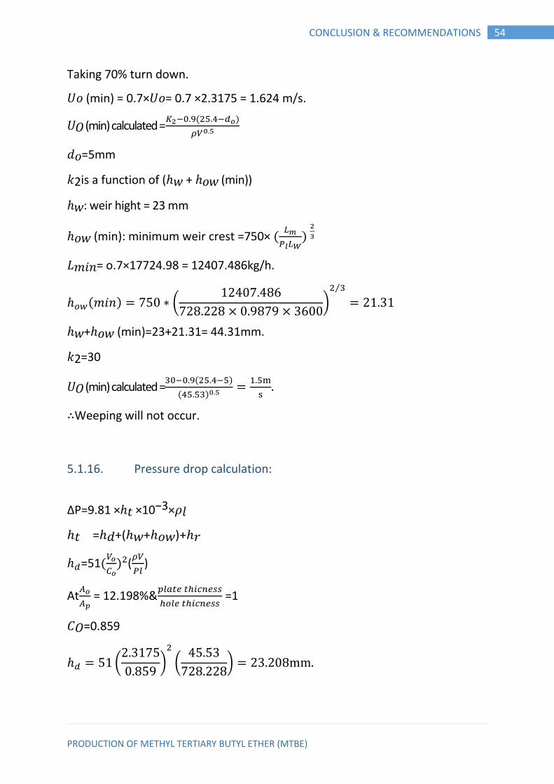
5.1.16. Pressure drop calculation:
∆P=9.81 × 𝑡 ×10−3× 𝑙
𝑡 = +( 𝑤+ 𝑜𝑤)+ 𝑟
=51(
) (
)
At
= 12.198%&
=1
𝑂=0.859
(
)
(
)
PRODUCTION OF METHYL TERTIARY BUTYL ETHER (MTBE)
55 CONCLUSION & RECOMMENDATIONS
(𝑚𝑖𝑛) ∗ (
)
⁄
𝑚𝑚
𝑤=23mm
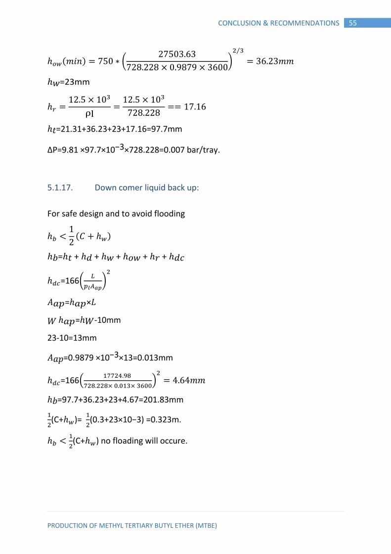
𝑡=21.31+36.23+23+17.16=97.7mm
∆P=9.81 ×97.7×10−3×728.228=0.007 bar/tray.
5.1.17. Down comer liquid back up:
For safe design and to avoid flooding
( )
𝑏= 𝑡 + + 𝑤 + 𝑜𝑤 + 𝑟 +
=166(
)
𝑝= 𝑝×𝐿
𝑊 𝑝= 𝑊-10mm
23-10=13mm
𝑝=0.9879 ×10−3×13=0.013mm
=166(
)
𝑚𝑚
𝑏=97.7+36.23+23+4.67=201.83mm
(C+ )=
(0.3+23×10−3) =0.323m.
(C+ ) no floading will occure.
PRODUCTION OF METHYL TERTIARY BUTYL ETHER (MTBE)
56 CONCLUSION & RECOMMENDATIONS
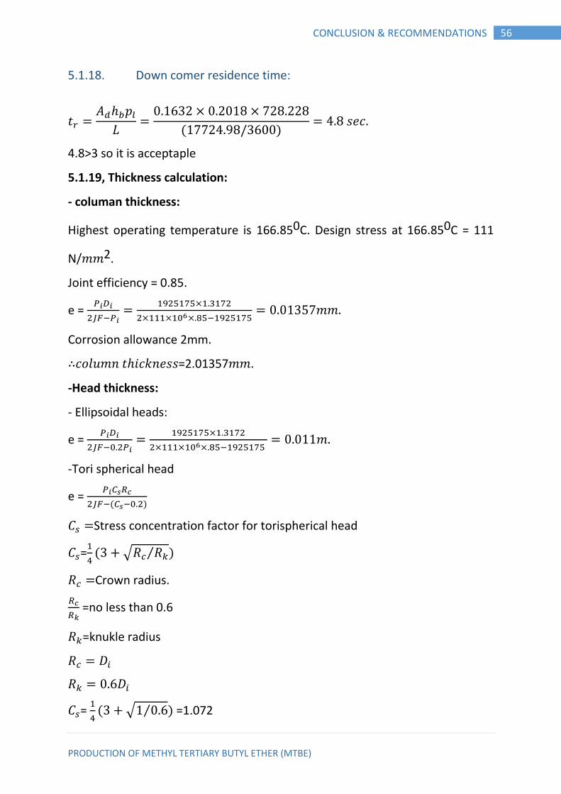
5.1.18. Down comer residence time:
𝑡 𝑝
𝐿
( ) 𝑠𝑒
4.8>3 so it is acceptaple
5.1.19, Thickness calculation:
- columan thickness:
Highest operating temperature is 166.850C. Design stress at 166.850C = 111
N/𝑚𝑚2.
Joint efficiency = 0.85.
e =
𝑚𝑚
Corrosion allowance 2mm.
∴ 𝑜𝑙𝑢𝑚𝑛 𝑡 𝑖 𝑘𝑛𝑒𝑠𝑠=2.01357𝑚𝑚.
-Head thickness:
- Ellipsoidal heads:
e =
𝑚
-Tori spherical head
e =
( )
Stress concentration factor for torispherical head
=
( √ ⁄ )
Crown radius.
=no less than 0.6
=knukle radius
=
( √ ⁄ ) =1.072
PRODUCTION OF METHYL TERTIARY BUTYL ETHER (MTBE)
57 CONCLUSION & RECOMMENDATIONS
J =1(No joint in head).
E
( ) = 0.01224mm.
Ellipsoidal heads IS recommended since it has the smallest thickness
∴ 𝑒 𝑡 𝑖 𝑘𝑛𝑒𝑠𝑠=0.011𝑚𝑚.
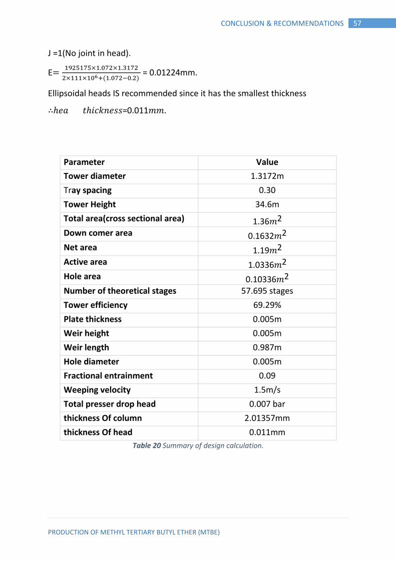
Parameter Value
Tower diameter 1.3172m
Tray spacing 0.30
Tower Height 34.6m
Total area(cross sectional area) 1.36𝑚2 Down comer area 0.1632𝑚2 Net area 1.19𝑚2 Active area 1.0336𝑚2 Hole area 0.10336𝑚2 Number of theoretical stages 57.695 stages
Tower efficiency 69.29%
Plate thickness 0.005m
Weir height 0.005m
Weir length 0.987m
Hole diameter 0.005m
Fractional entrainment 0.09
Weeping velocity 1.5m/s
Total presser drop head 0.007 bar
thickness Of column 2.01357mm
thickness Of head 0.011mm
Table 20 Summary of design calculation.
PRODUCTION OF METHYL TERTIARY BUTYL ETHER (MTBE)
58 CONCLUSION & RECOMMENDATIONS
CHAPTER SIX 6. CONCLUSION & RECOMMENDATIONS
Conclusion: 6.1.
• As shown in this study it is possible to produce 112,200tons /y of MTBE
with a purity of about 95% at a conversion of 80%.
• The design parameters of the selected distillation are: height 34.6 m,
number of trays 84 and diameter 1.32m.
• The specifications of the reactor needed for the process are: volume 65
m3, height 24.8.m, and diameter 1.8m.
Recommendations: 6.2.
Increasing annual frequency of renewing the catalyst increases
conversion and reduces the flow rate of the limited-supply isobutylene.
However, this may affect negatively costs and profitability due to the
high price of the catalyst hence an optimization technique must be
applied to determine the optimum values of these parameters.
It is recommended to perform an effective control study to construct
effective system controlling the critical parameters.
This study can be extended to investigate the feasibility of planning a process
that meets the foreign markets demand of MTBE.
PRODUCTION OF METHYL TERTIARY BUTYL ETHER (MTBE)
59 REFERENCES
7. REFERENCES
Adjeroh, D. A., 2015. DESIGN OF AN MTBE PRODUCTION PROCESS. West
Virginia: West Virginia University.
Al-Harthi, F., 2008.. Modeling and simulation of a reactive distillation unit for
production of MTBE. s.l.:King Saud University,.
Himmelblau, D. M. & Riggs, J. B., 2004. Basic Principles and Calculations in
Chemical. 7th Edition ed. Englewood Cliffs: Prentice Hall.
Lidderdale, T., 2000. MTBE, Oxygenates, and Motor Gasoline, s.l.: Energy
Information Administration .
Matyash, V. et al., 2016. Methyl Tertiary Butyl Ether (MTBE): 2016 World
Market Outlook and Forecast up to 2020. Birmingham : Merchant Research &
Consulting, Ltd..
Rocque, A. J., 2000. Use of Methyl Tertiray Butyl Ether (MTBE) as a Gasoline
Additive, Connecticut: Departmant of Enviromental Protection.
Winterberg, M., Schulte-Korne, E., Peters, U. & Nierlich, F., 2010. Methyl Tert-
Butyl Ether. In: Ullmann's Encyclopedia of Industrial Chemistry. Weinheim:
Wiley-VCH.