product manual for northstar air compressor · electric stationary air compressor ... compressor -...
TRANSCRIPT
1
M47500B.1
Owner’s Manual Electric Stationary Air Compressor
(230V, single phase/60 gallon, 3 HP and 5 HP) Instructions for Installation/Set-up, Operation, Maintenance, & Storage
This NorthStar® belt-driven compressor has a single-stage 2-cylinder pump (Model 47500) or single-stage 3-cylinder pump (Model 47501), made with heavy-duty cast iron cylinders for long life, and a compact design rated for 135 maximum PSI. Its continuous-duty rating ensures long-lasting performance, and its cast iron pump head ensures superior heat dissipation.
Read and understand this Owner’s Manual completely before using. Keep this manual for future review. Failure to properly set up, operate and maintain the compressor in accordance with this manual could result in serious injury or death to operator or bystanders.
WARNING: SPECIAL HAZARDS
Injection Injury: High-pressure air stream can pierce skin and underlying tissues, leading to serious injury and possible amputation. Such an injection injury can result in blood poisoning and/or severe tissue damage.
Flying Debris: High-pressure air stream can cause flying debris and possible surface damage.
Not For Breathing Air: NorthStar compressors are NOT designed, intended, or approved for supplying breathing air. No compressed air should be used for breathing unless air is treated in accordance with applicable standards.
Fire/Explosion: Sparks from air powered tool heads or attachments can ignite fuel or other flammable liquids or vapors in the vicinity. Exceeding the maximum pressure for air tools or attachments could cause them to explode. Keep a fire extinguisher rated "ABC" nearby
Burns: Compressor pump, motor and discharge tubing are hot surfaces that can cause burn injuries.
Electric Shock: Operating equipment in wet conditions or where not properly grounded can cause electric shock. Detailed safety information about these hazards appears throughout this manual.
Equipment Protection Quick Facts Inspect Upon Delivery: FIRST! Inspect for missing or damaged components. See “Initial Set-Up” section for where to report missing or damaged parts.
Check Pump Oil: Pump is shipped with oil. Check the pump oil level before starting. See “Preparing for Operation” section of this Owner’s Manual for capacity and viscosity.
Use Mechanical Lifting Equipment: Compressor is shipped on a pallet and is too heavy to handle manually. Use proper lifting equipment for unloading and moving to installation site.
Install Using a Qualified Electrician: All wiring, grounding, and electrical connections must be made by a qualified electrician. Install according to local and national codes.
Install a Regulator: We recommend installing a regulator on the compressor at each distribution point to maintain constant pressure in the outlet hose line and provide reduced pressure appropriate for air tool being used.
Run Pump Unloaded for Break-in Period: Before initial use, open ball valve and run compressor for 30 minutes to break in pump parts.
Follow Maintenance Schedule: Pump, air filter, and tank require periodic inspection and servicing to provide efficient function and long life. See “Maintenance Schedule” for frequency of servicing.
ITEM NUMBER: 47500 & 47501
SERIAL NUMBER: _____________
2
Table of Contents
Equipment Protection Quick Facts ........................................................................................................................................ 1
Table of Contents ........................................................................................................................................................ 2
About Your Air Compressor ....................................................................................................................................... 4
Specifications .............................................................................................................................................................. 5
Component Identification ........................................................................................................................................... 6
Safety Signal Words .................................................................................................................................................... 7 Hazard Signal Word Definitions ............................................................................................................................................ 7
Safety Labeling ............................................................................................................................................................ 8 Safety Decal Locations ......................................................................................................................................................... 8 Safety Decals ........................................................................................................................................................................ 9
Initial Set-Up .............................................................................................................................................................. 10 Step 1. Inspect & Unpack ...................................................................................................................................................... 10 Step 2. Assembly ................................................................................................................................................................... 10
Attach Air Filter.................................................................................................................................................................... 10 Attach Regulator (Recommended) ...................................................................................................................................... 10
Step 3. Select Suitable Location ........................................................................................................................................... 11 Step 4. Permanent Mounting ................................................................................................................................................ 11 Step 5. Installing Distribution Piping ................................................................................................................................... 12 Step 6. Wiring Installation ..................................................................................................................................................... 12
Electric Compatibility ........................................................................................................................................................... 12 Wire Size ............................................................................................................................................................................. 12 Circuit Breaker .................................................................................................................................................................... 13 Pressure Switch Wiring ....................................................................................................................................................... 13 ............................................................................................................................................................................................ 13 Grounding ........................................................................................................................................................................... 13 Model #47500 and #47501 (230 Volt; 3 / 5 HP) .................................................................................................................. 14 *Circuit Breaker ................................................................................................................................................................... 14 **Wire Size .......................................................................................................................................................................... 14 *Voltage .............................................................................................................................................................................. 14 *Circuit Breaker ................................................................................................................................................................... 15 **Wire Size .......................................................................................................................................................................... 15 *Voltage .............................................................................................................................................................................. 15
Operation ................................................................................................................................................................... 16 Follow Operation Safety Rules ............................................................................................................................................. 16 Prepare for Operation ............................................................................................................................................................ 16
Check/Add Oil to the Pump ................................................................................................................................................. 16 Proper Air Hose and Tool Use .............................................................................................................................................. 17
Pressure Control Related Devices ...................................................................................................................................... 17 Compressor - Tool Requirements ....................................................................................................................................... 17 Attaching/Disconnecting Air Hose and Tools ...................................................................................................................... 17
Using Compressor for Spraying ........................................................................................................................................... 18 Flammable Materials ........................................................................................................................................................... 18 Moisture in Compressed Air ................................................................................................................................................ 18
Shutdown ............................................................................................................................................................................... 18 Procedure ........................................................................................................................................................................... 18 For Malfunction During Operation ....................................................................................................................................... 18
Maintenance & Repair ............................................................................................................................................... 19
3
Maintenance Schedule Summary ............................................................................................................................. 19
Detailed Instructions – Maintenance & Repair ........................................................................................................ 19 Inspect Safety/Relief Valve ................................................................................................................................................. 19 Inspect Air Filter .................................................................................................................................................................. 19 Keep Compressor Clean ..................................................................................................................................................... 19 Inspect Compressor for Air Leaks ....................................................................................................................................... 20 Change Pump Oil ................................................................................................................................................................ 20 Drain Receiver Tank and Inspect Tank ............................................................................................................................... 20 Check Drive Belt for Tension and Alignment....................................................................................................................... 20 Keep Compressor Clean ..................................................................................................................................................... 21
Troubleshooting ........................................................................................................................................................ 22
Parts List – Model 47500 Rev B.1 ............................................................................................................................. 23
Parts List – Model 47500 Rev B.1 ............................................................................................................................. 24
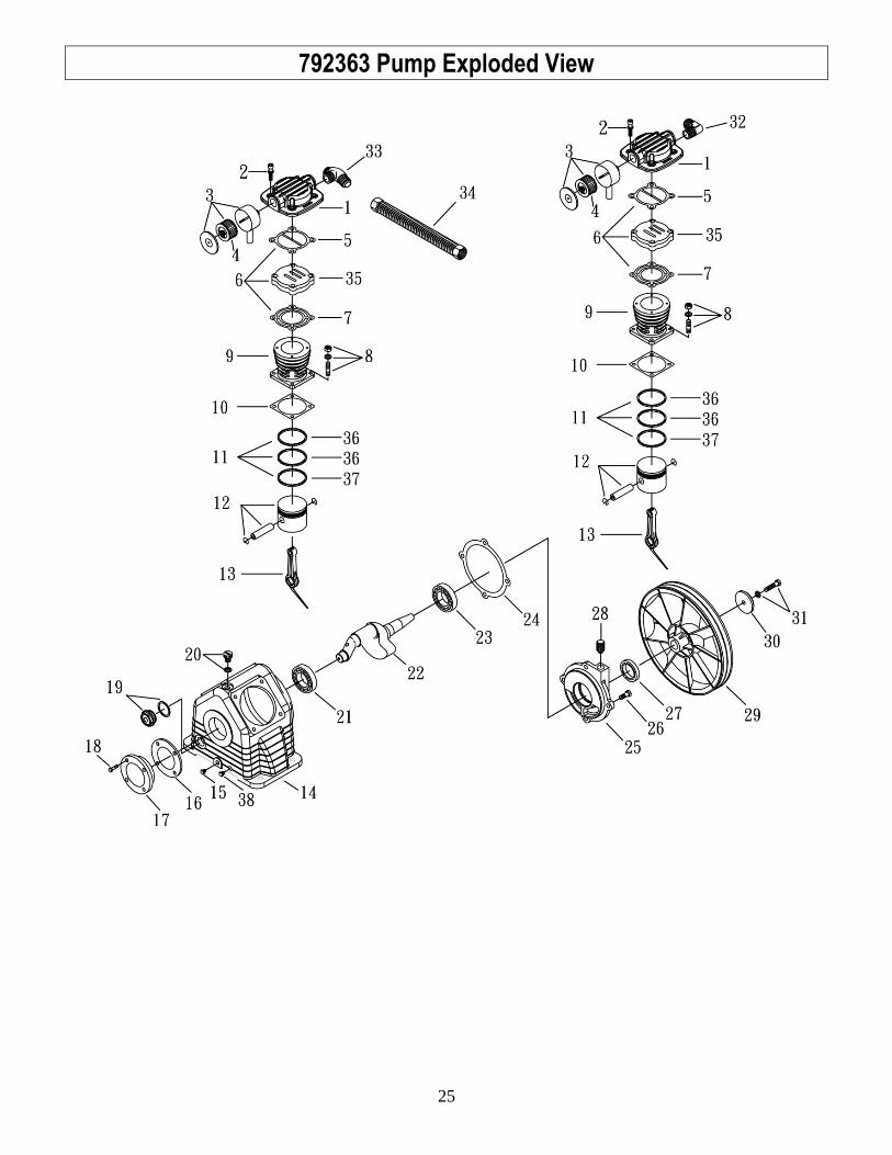
792363 Pump Exploded View ................................................................................................................................... 25
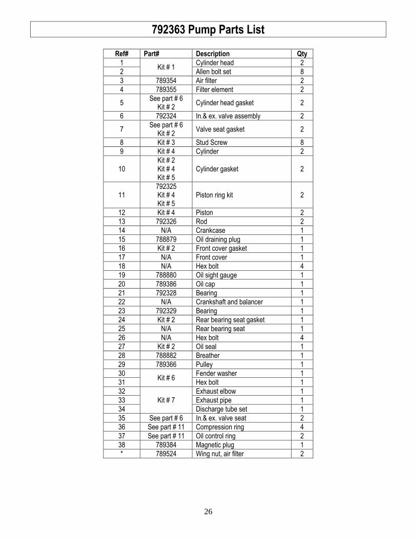
792363 Pump Parts List ............................................................................................................................................ 26
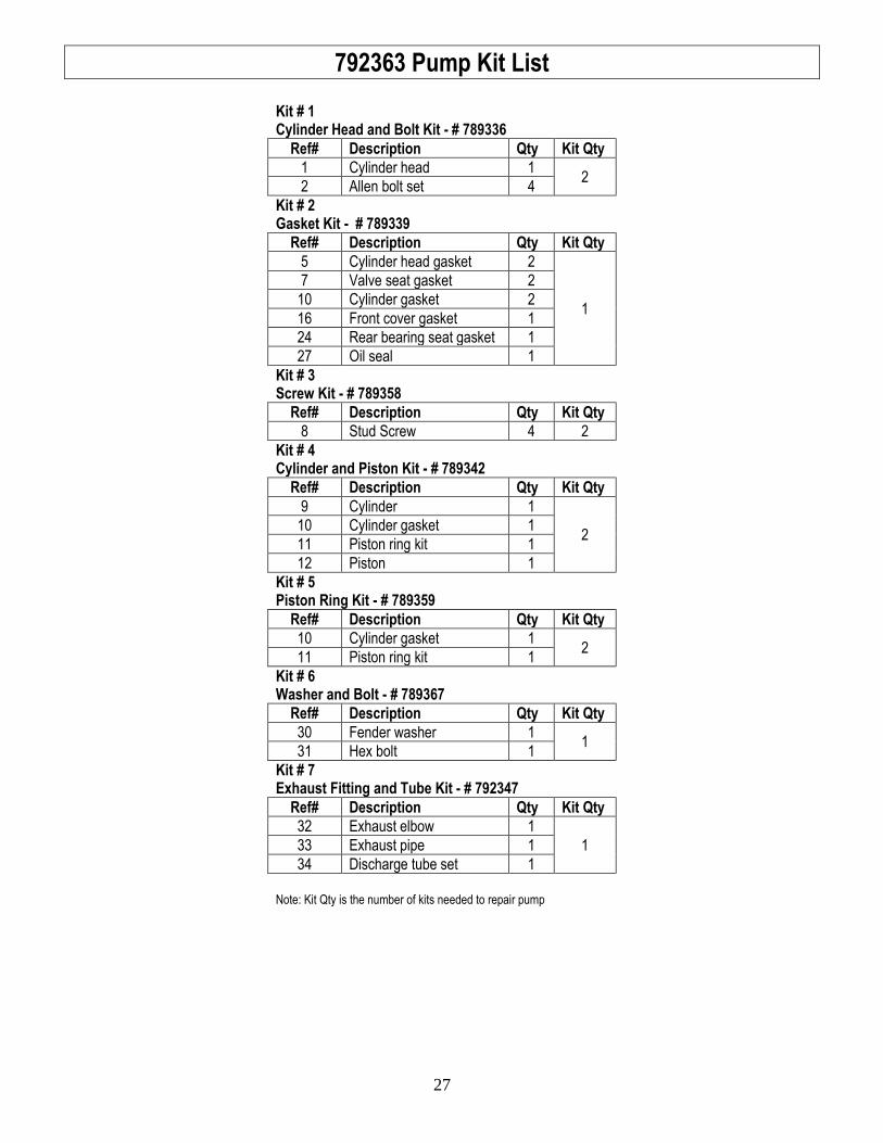
792363 Pump Kit List ................................................................................................................................................ 27
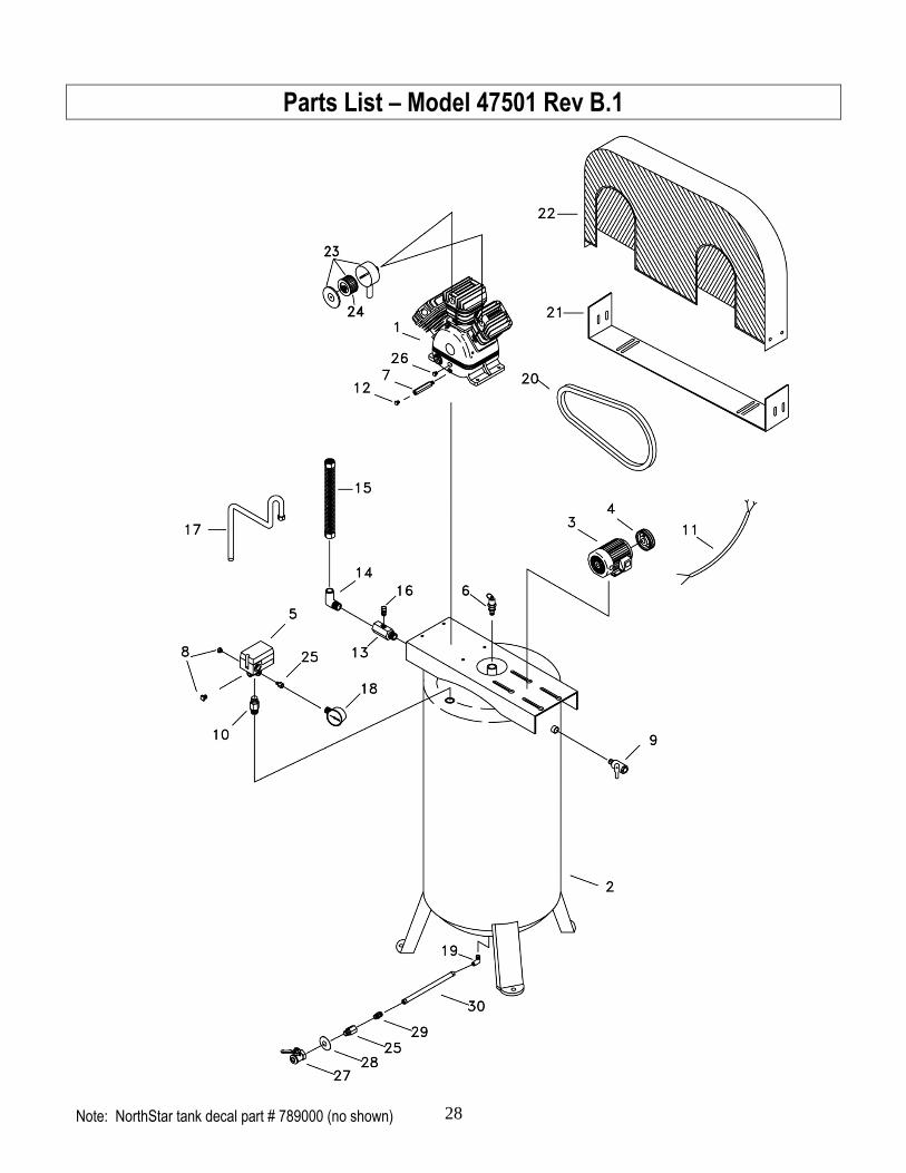
Parts List – Model 47501 Rev B.1 ............................................................................................................................. 28
Parts List – Model 47501 Rev B.1 ............................................................................................................................. 29
792373 Pump Parts List ............................................................................................................................................ 30
792373 Pump Parts List ............................................................................................................................................ 31
792373 Pump Parts List ............................................................................................................................................ 32
Appendix A: Lubricants and Compatibility ............................................................................................................. 33 Alternate Lubricants ............................................................................................................................................................ 33
Limited Warranty ....................................................................................................................................................... 34
4
About Your Air Compressor
Thank you for purchasing a NorthStar air compressor! It is designed for long life, dependability, and top performance.
Intended Use. Provides compressed air used primarily for operating air tools and pressurizing other objects that require high air pressure, such as tires. Do not use for low-pressure objects such as balloons, air mattresses, and sport balls, which can explode quickly and easily. Special precautions are necessary when used for cleaning to prevent flying debris hazards. It is not to be used to supply breathing air.
Supplies Required. Normal operation will require you to supply:
Pressure regulator (recommended) Pump oil Personal protection equipment
See “Specifications” section for more detail.
Site Location. Install in enclosed building only. See “Select Suitable Location” on page 11 for more information.
Personal Protection. Wear safety apparel during operation, including safety glasses with side and top protection.
Adult Control Only. Only trained adults should set up and operate the air compressor. Do not let children operate.
Under The Influence. Never operate, or let anyone else operate, the air compressor while fatigued or under the influence of alcohol, drugs, or medication.
Keep this manual for reference and review.
ATTENTION: Rental Companies and Private Owners who loan this equipment to others!
All persons to whom you rent/loan this air compressor must have access to and read this Owner’s Manual. Keep this manual with the air compressor at all times and advise all persons who will operate the machine to read it. You must also provide personal instruction on how to safely set-up and operate the air compressor and remain available to answer any questions a renter/borrower might have. Owner’s Manuals are available from NorthStar at 1-800-270-0810.
For any questions, comments, problems or part orders, call NorthStar at 1-800-270-0810.
5
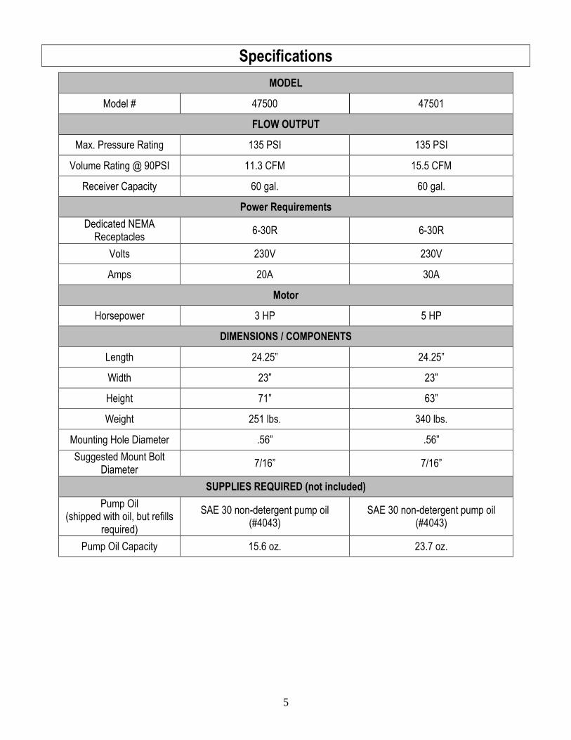
Specifications
MODEL
Model # 47500 47501
FLOW OUTPUT
Max. Pressure Rating 135 PSI 135 PSI
Volume Rating @ 90PSI 11.3 CFM 15.5 CFM
Receiver Capacity 60 gal. 60 gal.
Power Requirements
Dedicated NEMA Receptacles
6-30R 6-30R
Volts 230V 230V
Amps 20A 30A
Motor
Horsepower 3 HP 5 HP
DIMENSIONS / COMPONENTS
Length 24.25” 24.25”
Width 23” 23”
Height 71” 63”
Weight 251 lbs. 340 lbs.
Mounting Hole Diameter .56” .56”
Suggested Mount Bolt Diameter
7/16” 7/16”
SUPPLIES REQUIRED (not included)
Pump Oil (shipped with oil, but refills
required)
SAE 30 non-detergent pump oil (#4043)
SAE 30 non-detergent pump oil (#4043)
Pump Oil Capacity 15.6 oz. 23.7 oz.
6
Component Identification
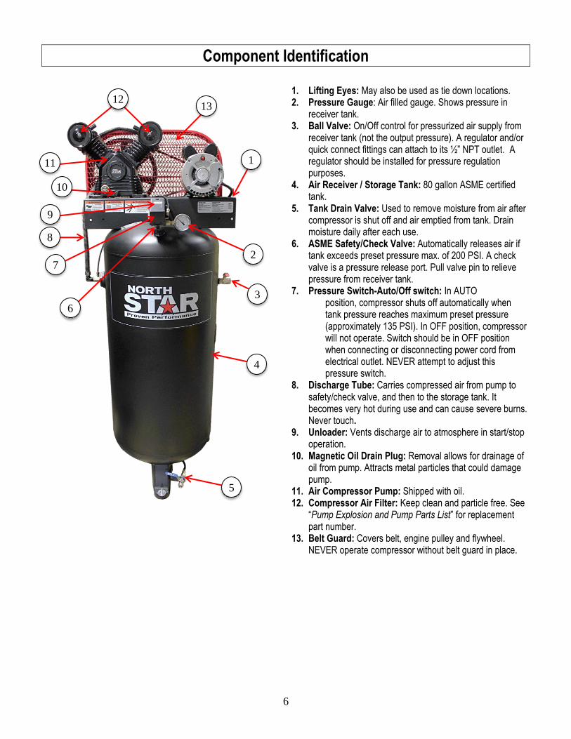
1. Lifting Eyes: May also be used as tie down locations. 2. Pressure Gauge: Air filled gauge. Shows pressure in
receiver tank. 3. Ball Valve: On/Off control for pressurized air supply from
receiver tank (not the output pressure). A regulator and/or quick connect fittings can attach to its ½” NPT outlet. A regulator should be installed for pressure regulation purposes.
4. Air Receiver / Storage Tank: 80 gallon ASME certified tank.
5. Tank Drain Valve: Used to remove moisture from air after compressor is shut off and air emptied from tank. Drain moisture daily after each use.
6. ASME Safety/Check Valve: Automatically releases air if tank exceeds preset pressure max. of 200 PSI. A check valve is a pressure release port. Pull valve pin to relieve pressure from receiver tank.
7. Pressure Switch-Auto/Off switch: In AUTO position, compressor shuts off automatically when tank pressure reaches maximum preset pressure (approximately 135 PSI). In OFF position, compressor will not operate. Switch should be in OFF position when connecting or disconnecting power cord from electrical outlet. NEVER attempt to adjust this pressure switch.
8. Discharge Tube: Carries compressed air from pump to safety/check valve, and then to the storage tank. It becomes very hot during use and can cause severe burns. Never touch.
9. Unloader: Vents discharge air to atmosphere in start/stop operation.
10. Magnetic Oil Drain Plug: Removal allows for drainage of oil from pump. Attracts metal particles that could damage pump.
11. Air Compressor Pump: Shipped with oil. 12. Compressor Air Filter: Keep clean and particle free. See
“Pump Explosion and Pump Parts List” for replacement part number.
13. Belt Guard: Covers belt, engine pulley and flywheel. NEVER operate compressor without belt guard in place.
3
1
2
4
8
9
5
6
7
11
13
10
12
7
Safety Signal Words
Hazard Signal Word Definitions
DANGER
WARNING
CAUTION
CAUTION
NOTICE
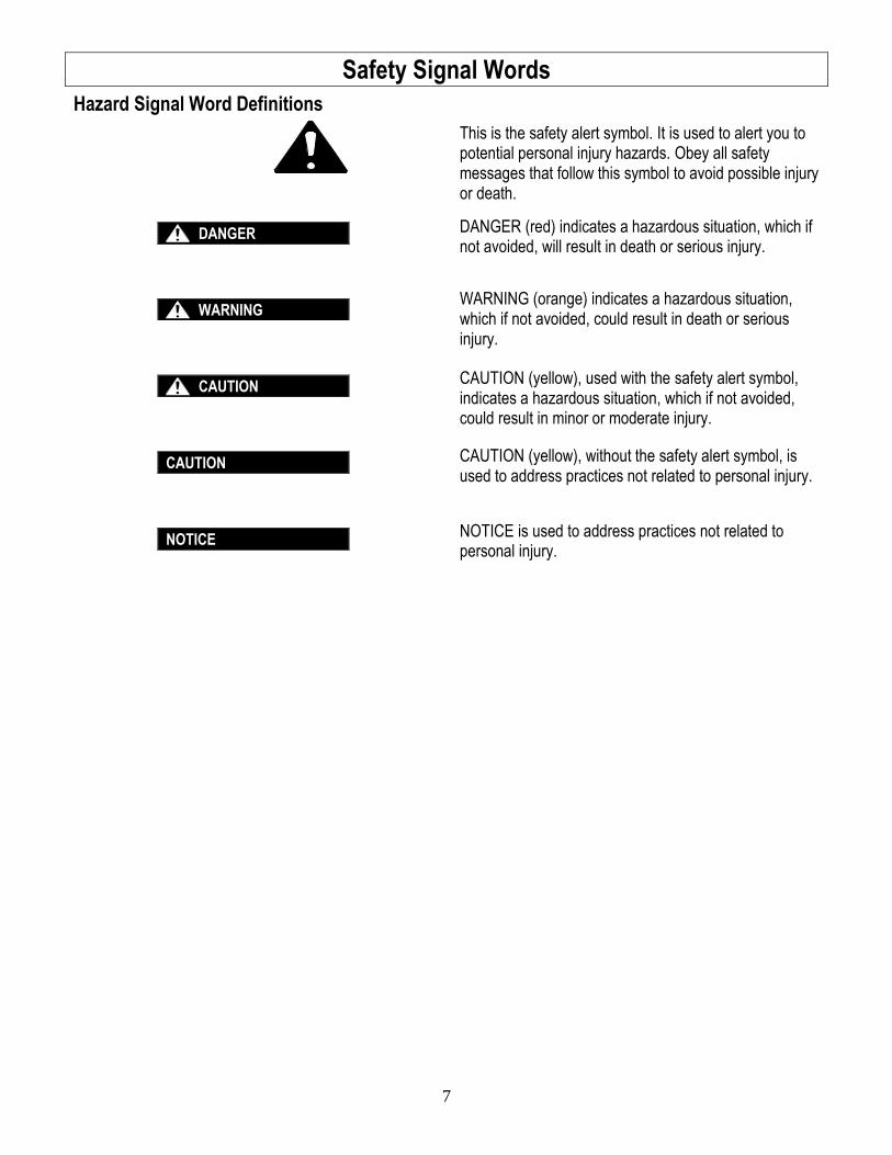
This is the safety alert symbol. It is used to alert you to potential personal injury hazards. Obey all safety messages that follow this symbol to avoid possible injury or death.
DANGER (red) indicates a hazardous situation, which if not avoided, will result in death or serious injury.
WARNING (orange) indicates a hazardous situation, which if not avoided, could result in death or serious injury.
CAUTION (yellow), used with the safety alert symbol, indicates a hazardous situation, which if not avoided, could result in minor or moderate injury.
CAUTION (yellow), without the safety alert symbol, is used to address practices not related to personal injury.
NOTICE is used to address practices not related to personal injury.
8
Safety Labeling
Safety Decal Locations
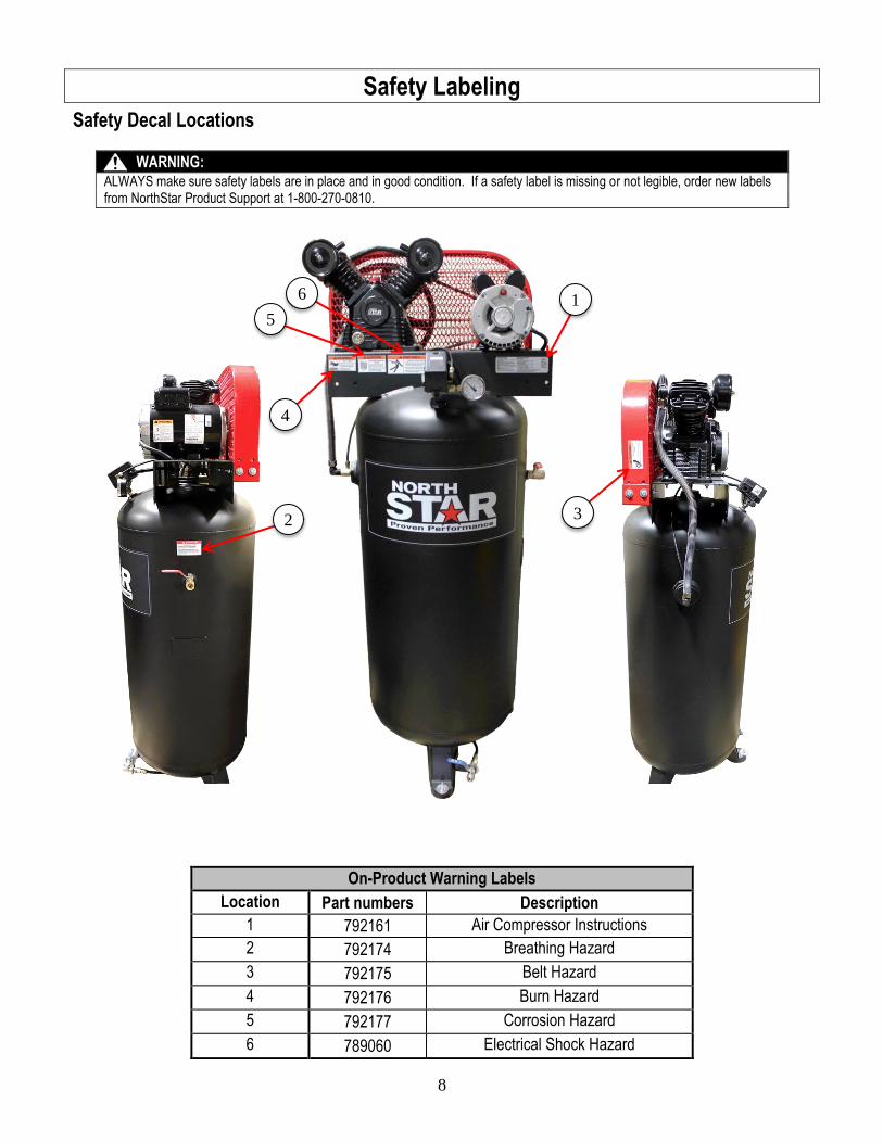
WARNING:
ALWAYS make sure safety labels are in place and in good condition. If a safety label is missing or not legible, order new labels from NorthStar Product Support at 1-800-270-0810.
On-Product Warning Labels
Location Part numbers Description
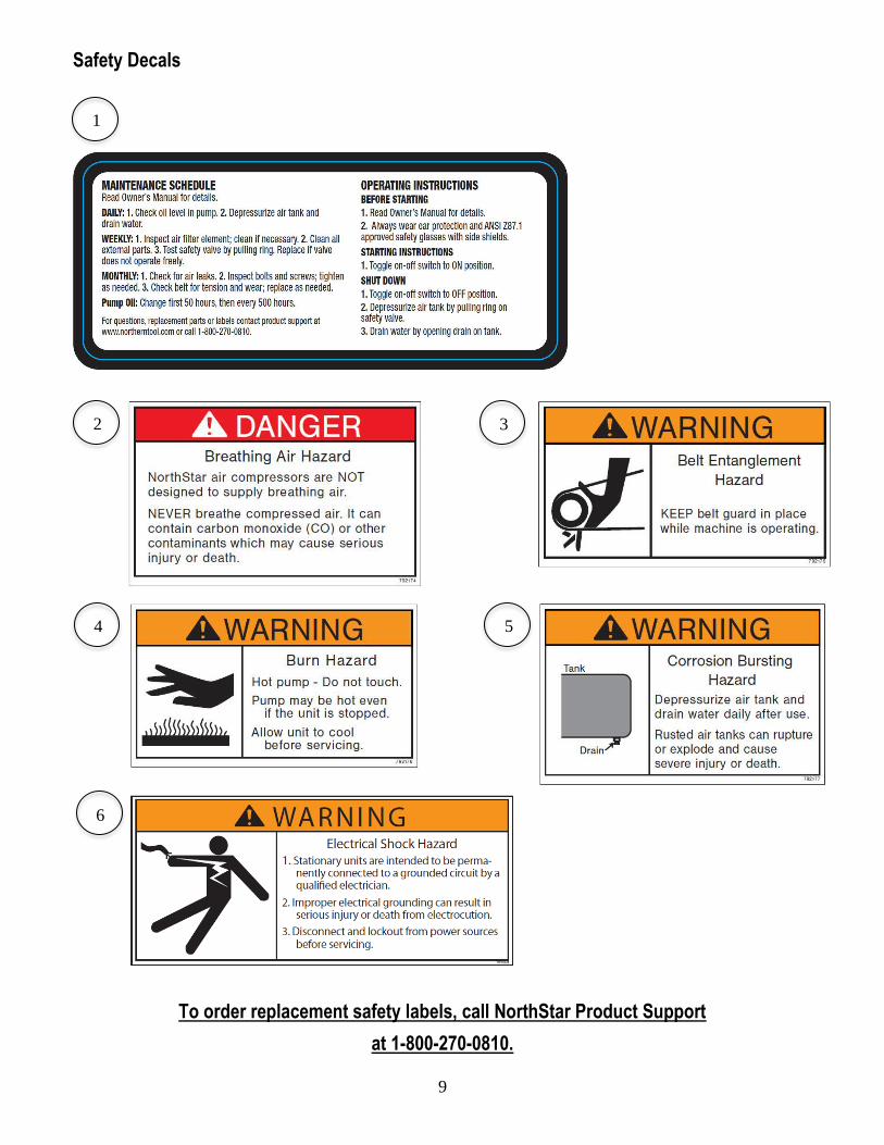
1 792161 Air Compressor Instructions
2 792174 Breathing Hazard
3 792175 Belt Hazard
4 792176 Burn Hazard
5 792177 Corrosion Hazard
6 789060 Electrical Shock Hazard
1
2 3
6
5
4
9
Safety Decals
To order replacement safety labels, call NorthStar Product Support
at 1-800-270-0810.
1
2
6
3
4 5
10
Initial Set-Up
Step 1. Inspect & Unpack Upon receipt, inspect air compressor for missing or damaged parts. Verify that it is the compressor you ordered.
See “Component Identification” section of this manual for a diagram of the compressor and its components.
For missing or damaged components, please contact NorthStar Product Support at 1-800-270-0810.
If complete, fill out product serial number information. See “Limited Warranty” section of this manual.
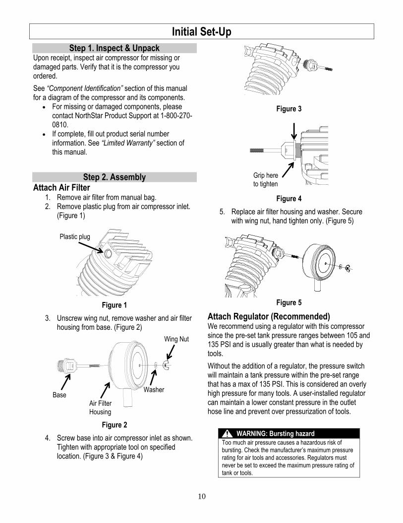
Step 2. Assembly Attach Air Filter
1. Remove air filter from manual bag. 2. Remove plastic plug from air compressor inlet.
(Figure 1)
Figure 1
3. Unscrew wing nut, remove washer and air filter housing from base. (Figure 2)
Figure 2
4. Screw base into air compressor inlet as shown. Tighten with appropriate tool on specified location. (Figure 3 & Figure 4)
Figure 3
Figure 4
5. Replace air filter housing and washer. Secure with wing nut, hand tighten only. (Figure 5)
Figure 5
Attach Regulator (Recommended) We recommend using a regulator with this compressor since the pre-set tank pressure ranges between 105 and 135 PSI and is usually greater than what is needed by tools.
Without the addition of a regulator, the pressure switch will maintain a tank pressure within the pre-set range that has a max of 135 PSI. This is considered an overly high pressure for many tools. A user-installed regulator can maintain a lower constant pressure in the outlet hose line and prevent over pressurization of tools.
WARNING: Bursting hazard
Too much air pressure causes a hazardous risk of bursting. Check the manufacturer’s maximum pressure rating for air tools and accessories. Regulators must never be set to exceed the maximum pressure rating of tank or tools.
Plastic plug
Base Air Filter
Housing
Washer
Wing Nut
Grip here
to tighten
11
Step 3. Select Suitable Location
WARNING: Lifting hazard
The compressor is heavy. Ensure that proper lifting equipment is available to unload and move compressor to installation site.
Location Criteria: Enclosed building only. Where no flammable vapors, dusts, and gases
are present. At least 15” away from walls and other objects. Away from other heat-generating equipment. Away from dusty/dirty conditions. In a well illuminated area. Where proper wire size is already, or can be
made, available.
Positioning: The compressor should be mounted on a dry,
firm, and level surface. It must sit level and be stabilized since it will slide or shift during operation if not secured.
Airflow: Provide access to adequate, clean and
unobstructed airflow for cooling and air supply. Remember the supply air is passing through the
compressor supply hoses and tools. These can be damaged or have a shortened life if unclean air is present or air filter is not clean and functioning properly.
Do not allow debris to accumulate or block airflow.
Do not operate with a tarp, blanket, or cover surrounding the machine, which blocks air flow.
Do not place any objects against or on top of the unit, which can also block airflow or damage unit.
Electrical: MUST be connected to a 230 Volt, single-phase
outlet having operating capacity of 20 amp (Model #47500, 3 HP) or 30 amp (Model #47501, 5 HP).
Wiring: Proper wire size should take into consideration
length from distribution panel. See Step 6, “Wiring Installation” for more
information.
Ideal operating temperatures:
40 and 100F (4 and 37C).
Operating Limitations:
15F (-9C) or above 125F (52C).
If temperatures consistently drop below 32 F (0C), install within an enclosed heated building. If this is not possible, protect the safety/relief and drain valves from freezing.
Note: Excessive moisture is likely to occur if unit is stored in an unheated area subject to large temperature changes. Moisture forming in pump can produce sludge in the oil, causing parts to wear out prematurely. Excessive condensation on the pump when it cools down is a sign that this may be occurring.
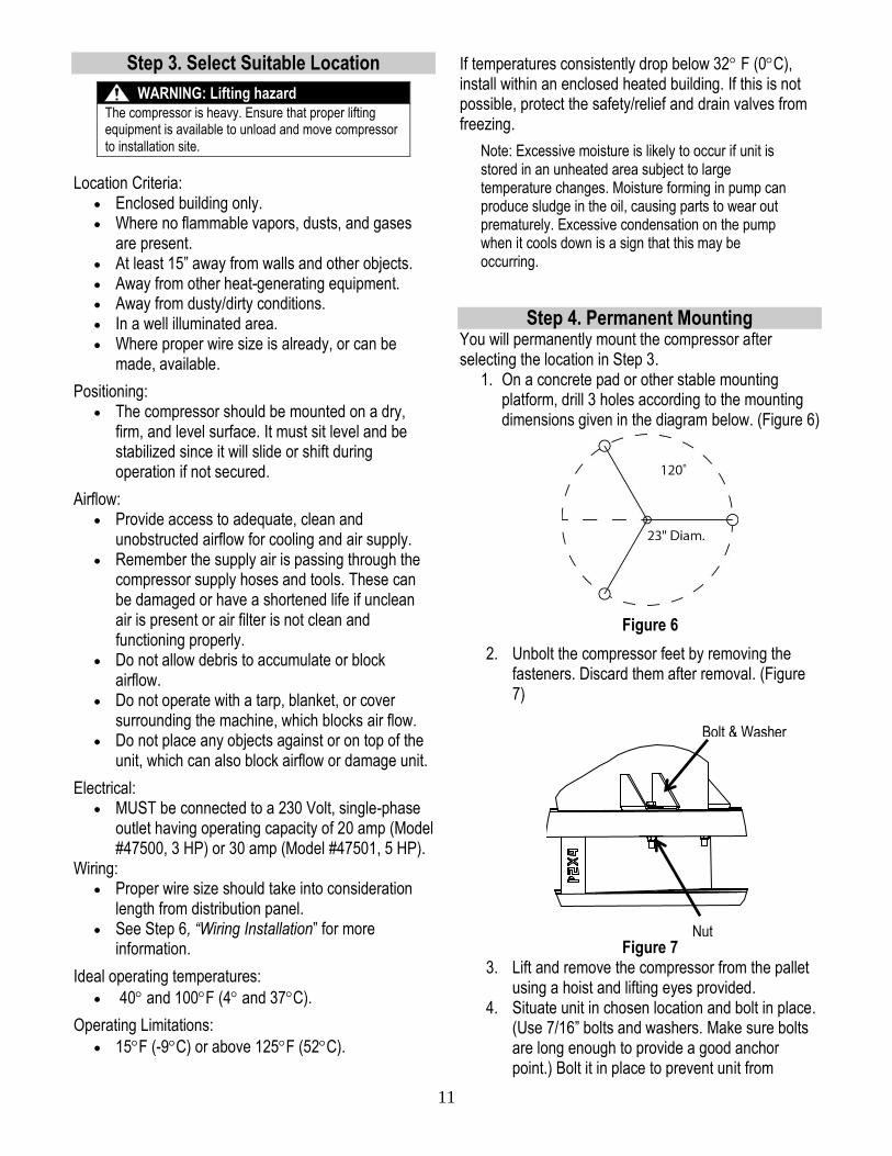
Step 4. Permanent Mounting You will permanently mount the compressor after selecting the location in Step 3.
1. On a concrete pad or other stable mounting platform, drill 3 holes according to the mounting dimensions given in the diagram below. (Figure 6)
Figure 6
2. Unbolt the compressor feet by removing the fasteners. Discard them after removal. (Figure 7)
Figure 7 3. Lift and remove the compressor from the pallet
using a hoist and lifting eyes provided. 4. Situate unit in chosen location and bolt in place.
(Use 7/16” bolts and washers. Make sure bolts are long enough to provide a good anchor point.) Bolt it in place to prevent unit from
Nut
Bolt & Washer
12
vibrating excessively. Use metal shims under the “short” feet if necessary.
5. A rubber isolation mat or pads may be used under each mounting foot to reduce vibration.
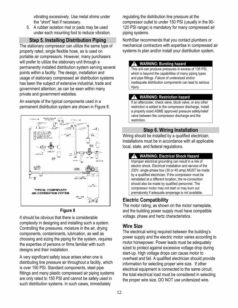
Step 5. Installing Distribution Piping The stationary compressor can utilize the same type of properly rated, single flexible hose, as is used on portable air compressors. However, many purchasers will prefer to utilize the stationary unit through a permanently installed distribution system serving several points within a facility. The design, installation and usage of stationary compressed air distribution systems has been the subject of extensive industrial, trade and government attention, as can be seen within many private and government websites.
An example of the typical components used in a permanent distribution system are shown in Figure 8.
Figure 8
It should be obvious that there is considerable complexity in designing and installing such a system. Controlling the pressures, moisture in the air, drying components, contaminants, lubrication, as well as choosing and sizing the piping for the system, requires the expertise of persons or firms familiar with such designs and their installation.
A very significant safety issue arises when one is distributing line pressure air throughout a facility, which is over 150 PSI. Standard components, steel pipe fittings and many plastic compressed air piping systems are only rated to 150 PSI and cannot be safely used in such distribution systems. In such cases, immediately
regulating the distribution line pressure at the compressor outlet to under 150 PSI (usually in the 90-120 PSI range) is mandatory for many compressed air piping systems.
NorthStar recommends that you contact plumbers or mechanical contractors with expertise in compressed air systems to plan and/or install your distribution system.
WARNING: Bursting hazard
This unit can produce pressures in excess of 135 PSI, which is beyond the capabilities of many piping types and pipe fittings. Failure of undersized and/or inadequate distribution components can lead to serious injury.
WARNING: Restriction hazard
If an aftercooler, check valve, block valve, or any other restriction is added to the compressor discharge, install a properly sized ASME approved pressure safety/relief valve between the compressor discharge and the restriction.
Step 6. Wiring Installation Wiring should be installed by a qualified electrician. Installations must be in accordance with all applicable local, state, and federal regulations.
WARNING: Electrical Shock Hazard
Improper electrical grounding can result in a risk of electric shock. Electrical installation and service of the 230V, single-phase box (30 or 40 amp) MUST be made by a qualified electrician. If the compressor must be reinstalled at a different location, the re-connection should also be made by qualified personnel. The compressor motor may not start or may burn out prematurely if adequate amperage is not available.
Electric Compatibility The motor rating, as shown on the motor nameplate, and the building power supply must have compatible voltage, phase and hertz characteristics. Wire Size The electrical wiring required between the building’s power supply and the electric motor varies according to motor horsepower. Power leads must be adequately sized to protect against excessive voltage drop during start-up. High voltage drops can cause motor to overheat and fail. A qualified electrician should provide information for selecting proper wire size. If other electrical equipment is connected to the same circuit, the total electrical load must be considered in selecting the proper wire size. DO NOT use undersized wire.
13
CAUTION: Inadequate wiring hazard
Overheating, short-circuiting and fire damage will result from inadequate wire sizing.
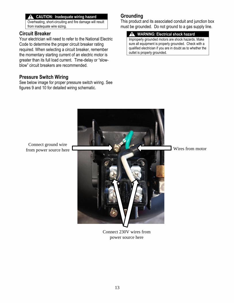
Circuit Breaker Your electrician will need to refer to the National Electric Code to determine the proper circuit breaker rating required. When selecting a circuit breaker, remember the momentary starting current of an electric motor is greater than its full load current. Time-delay or “slow-blow” circuit breakers are recommended.
Pressure Switch Wiring See below image for proper pressure switch wiring. See figures 9 and 10 for detailed wiring schematic.
Grounding This product and its associated conduit and junction box must be grounded. Do not ground to a gas supply line.
WARNING: Electrical shock hazard
Improperly grounded motors are shock hazards. Make sure all equipment is properly grounded. Check with a qualified electrician if you are in doubt as to whether the outlet is properly grounded.
Connect ground wire
from power source here
Connect 230V wires from
power source here
Wires from motor
14
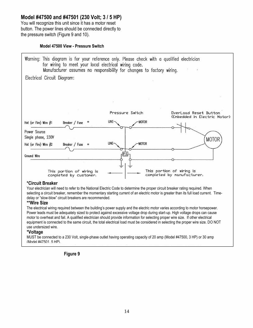
Model #47500 and #47501 (230 Volt; 3 / 5 HP) You will recognize this unit since it has a motor reset button. The power lines should be connected directly to the pressure switch (Figure 9 and 10).
Model 47500 View - Pressure Switch
Figure 9
*Circuit Breaker Your electrician will need to refer to the National Electric Code to determine the proper circuit breaker rating required. When selecting a circuit breaker, remember the momentary starting current of an electric motor is greater than its full load current. Time-delay or “slow-blow” circuit breakers are recommended.
**Wire Size The electrical wiring required between the building’s power supply and the electric motor varies according to motor horsepower. Power leads must be adequately sized to protect against excessive voltage drop during start-up. High voltage drops can cause motor to overheat and fail. A qualified electrician should provide information for selecting proper wire size. If other electrical equipment is connected to the same circuit, the total electrical load must be considered in selecting the proper wire size. DO NOT use undersized wire.
*Voltage MUST be connected to a 230 Volt, single-phase outlet having operating capacity of 20 amp (Model #47500, 3 HP) or 30 amp (Model #47501, 5 HP).
*
*
15
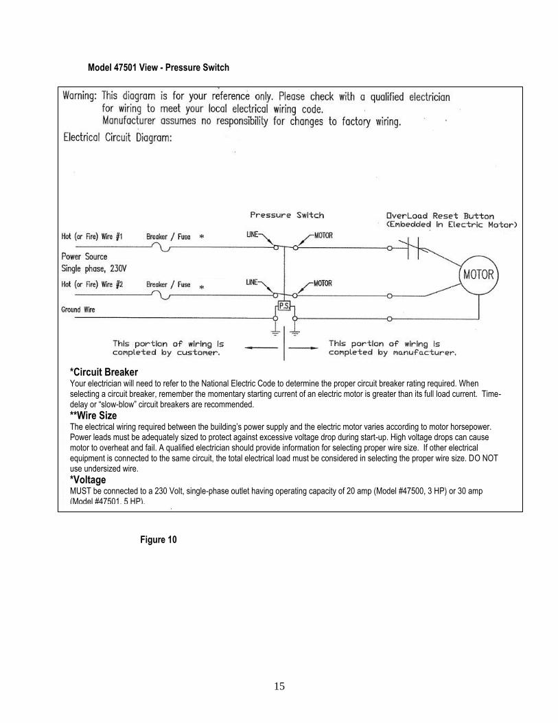
Model 47501 View - Pressure Switch
Figure 10
*Circuit Breaker Your electrician will need to refer to the National Electric Code to determine the proper circuit breaker rating required. When selecting a circuit breaker, remember the momentary starting current of an electric motor is greater than its full load current. Time-delay or “slow-blow” circuit breakers are recommended.
**Wire Size The electrical wiring required between the building’s power supply and the electric motor varies according to motor horsepower. Power leads must be adequately sized to protect against excessive voltage drop during start-up. High voltage drops can cause motor to overheat and fail. A qualified electrician should provide information for selecting proper wire size. If other electrical equipment is connected to the same circuit, the total electrical load must be considered in selecting the proper wire size. DO NOT use undersized wire.
*Voltage MUST be connected to a 230 Volt, single-phase outlet having operating capacity of 20 amp (Model #47500, 3 HP) or 30 amp (Model #47501, 5 HP).
*
*
16
Operation
Follow Operation Safety Rules Before starting the compressor, review the safety rules found below and throughout the manual.
WARNING
Failure to follow safety rules may result in serious injury or death to the operator or bystanders.
Instruct Operators. Owner must instruct all operators in safe set-up and operation. Do not allow anyone to operate the compressor who has not read the Owner’s Manual.
Safety Guarding. Only operate with safety covers, guards and barriers secured and in good working order.
Moving Parts. Keep hands, feet, hair and apparel away from moving parts. Never remove any guards while the unit is operating. Do not reach into an air vent or cavity, as they may cover dangerous moving parts.
Ear Protection. Hearing can be damaged from prolonged, close-range exposure to the noise level produced by this compressor. Ear plugs or other hearing protection is recommended for persons working who are exposed within 15-20 feet of the running compressor for an extended period of time.
Eye Protection. Wear ANSI/OSHA required “Z87.1” safety glasses when operating or servicing the compressor. Pressurized air spray from this unit can cause severe injury to the eyes. Also, small objects will become airborne as the air spray contacts them.
Respirator. Wear a respirator when using the compressed air for spraying. Spray in a well- ventilated area to prevent health and fire hazards.
Prepare for Operation Make sure that any regular maintenance has been performed as prescribed in “Maintenance & Repair” section.
Drain receiver tank of any moisture. Inspect for oil leaks. Check for any unusual noise/vibration. Ensure the area around compressor is free from
rags, tools, debris and flammable or explosive materials.
Ensure belt guards and covers are securely in place.
WARNING: Entanglement hazard
Do NOT operate with protective covers or guards removed. Beneath these covers are high speed moving components, which can entangle the operator or bystanders. Entanglement in this equipment may result in serious injury, amputation or death.
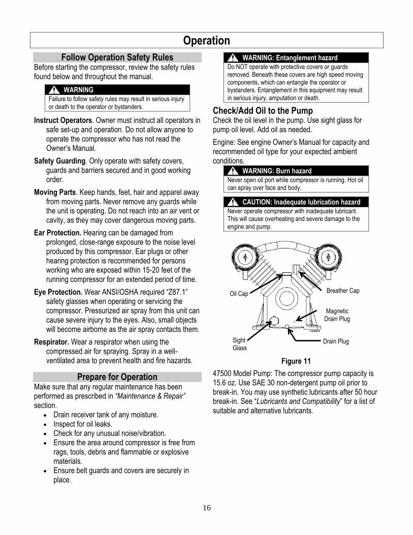
Check/Add Oil to the Pump Check the oil level in the pump. Use sight glass for pump oil level. Add oil as needed.
Engine: See engine Owner’s Manual for capacity and recommended oil type for your expected ambient conditions.
WARNING: Burn hazard
Never open oil port while compressor is running. Hot oil can spray over face and body.
CAUTION: Inadequate lubrication hazard
Never operate compressor with inadequate lubricant. This will cause overheating and severe damage to the engine and pump.
Figure 11
47500 Model Pump: The compressor pump capacity is 15.6 oz. Use SAE 30 non-detergent pump oil prior to break-in. You may use synthetic lubricants after 50 hour break-in. See “Lubricants and Compatibility” for a list of suitable and alternative lubricants.
Oil Cap
Sight Glass
Drain Plug
Breather Cap
Magnetic Drain Plug
17
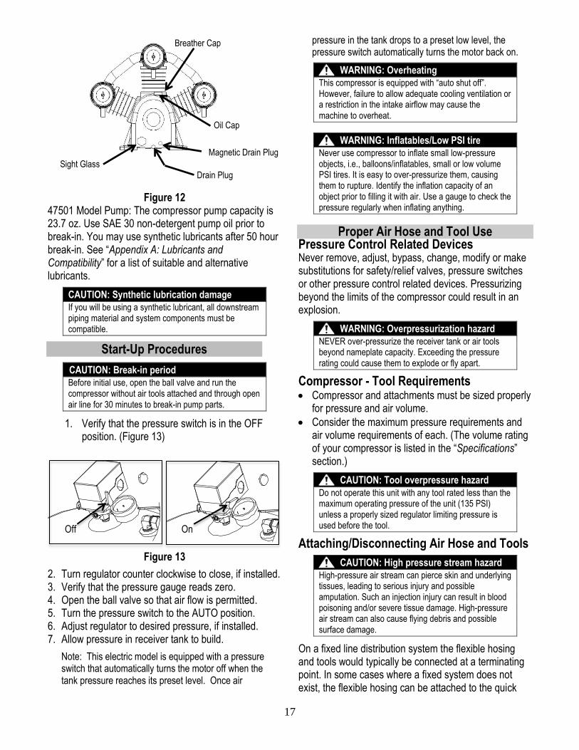
Figure 12
47501 Model Pump: The compressor pump capacity is 23.7 oz. Use SAE 30 non-detergent pump oil prior to break-in. You may use synthetic lubricants after 50 hour break-in. See “Appendix A: Lubricants and Compatibility” for a list of suitable and alternative lubricants.
CAUTION: Synthetic lubrication damage
If you will be using a synthetic lubricant, all downstream piping material and system components must be compatible.
Start-Up Procedures
CAUTION: Break-in period
Before initial use, open the ball valve and run the compressor without air tools attached and through open air line for 30 minutes to break-in pump parts.
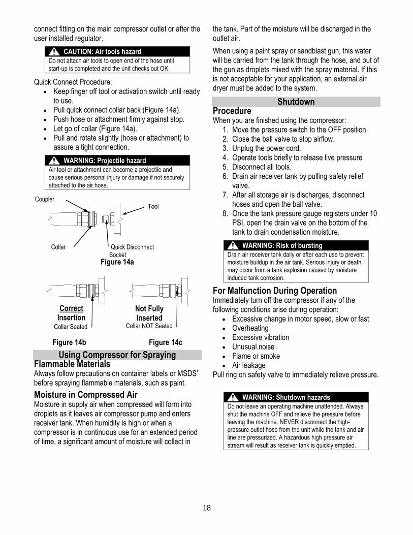
1. Verify that the pressure switch is in the OFF position. (Figure 13)
Figure 13
2. Turn regulator counter clockwise to close, if installed. 3. Verify that the pressure gauge reads zero. 4. Open the ball valve so that air flow is permitted. 5. Turn the pressure switch to the AUTO position. 6. Adjust regulator to desired pressure, if installed. 7. Allow pressure in receiver tank to build.
Note: This electric model is equipped with a pressure switch that automatically turns the motor off when the tank pressure reaches its preset level. Once air
pressure in the tank drops to a preset low level, the pressure switch automatically turns the motor back on.
WARNING: Overheating
This compressor is equipped with “auto shut off”. However, failure to allow adequate cooling ventilation or a restriction in the intake airflow may cause the machine to overheat.
WARNING: Inflatables/Low PSI tire
Never use compressor to inflate small low-pressure objects, i.e., balloons/inflatables, small or low volume PSI tires. It is easy to over-pressurize them, causing them to rupture. Identify the inflation capacity of an object prior to filling it with air. Use a gauge to check the pressure regularly when inflating anything.
Proper Air Hose and Tool Use Pressure Control Related Devices Never remove, adjust, bypass, change, modify or make substitutions for safety/relief valves, pressure switches or other pressure control related devices. Pressurizing beyond the limits of the compressor could result in an explosion.
WARNING: Overpressurization hazard
NEVER over-pressurize the receiver tank or air tools beyond nameplate capacity. Exceeding the pressure rating could cause them to explode or fly apart.
Compressor - Tool Requirements Compressor and attachments must be sized properly
for pressure and air volume.
Consider the maximum pressure requirements and air volume requirements of each. (The volume rating of your compressor is listed in the “Specifications” section.)
CAUTION: Tool overpressure hazard
Do not operate this unit with any tool rated less than the maximum operating pressure of the unit (135 PSI) unless a properly sized regulator limiting pressure is used before the tool.
Attaching/Disconnecting Air Hose and Tools
CAUTION: High pressure stream hazard
High-pressure air stream can pierce skin and underlying tissues, leading to serious injury and possible amputation. Such an injection injury can result in blood poisoning and/or severe tissue damage. High-pressure air stream can also cause flying debris and possible surface damage.
On a fixed line distribution system the flexible hosing and tools would typically be connected at a terminating point. In some cases where a fixed system does not exist, the flexible hosing can be attached to the quick
Magnetic Drain Plug
Drain Plug
Oil Cap
Breather Cap
Sight Glass
On Off
18
connect fitting on the main compressor outlet or after the user installed regulator.
CAUTION: Air tools hazard
Do not attach air tools to open end of the hose until start-up is completed and the unit checks out OK.
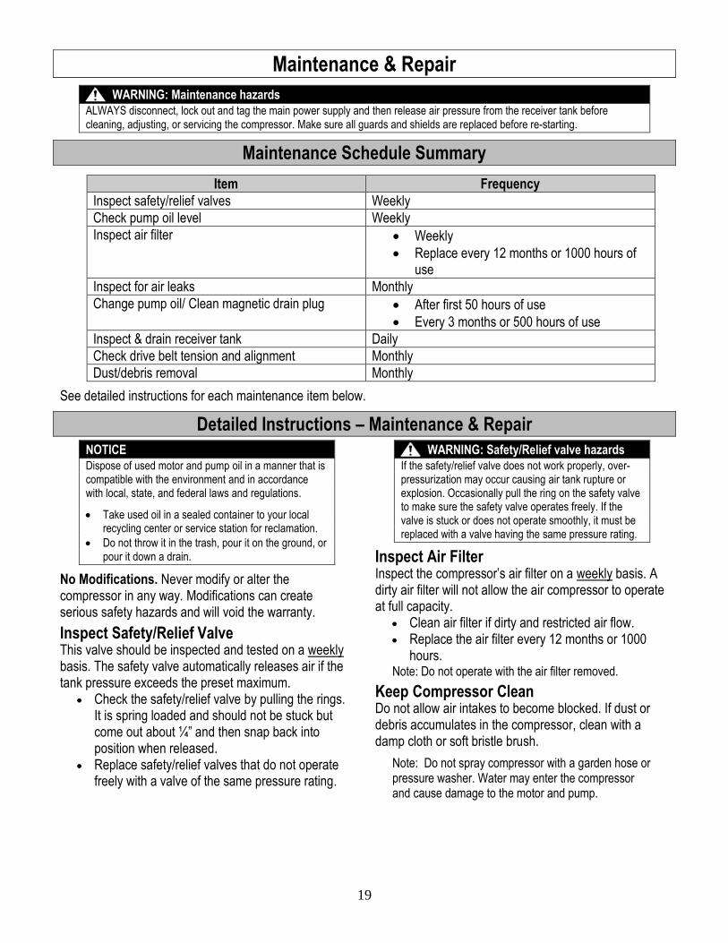
Quick Connect Procedure: Keep finger off tool or activation switch until ready
to use. Pull quick connect collar back (Figure 14a). Push hose or attachment firmly against stop. Let go of collar (Figure 14a). Pull and rotate slightly (hose or attachment) to
assure a tight connection.
WARNING: Projectile hazard
Air tool or attachment can become a projectile and cause serious personal injury or damage if not securely attached to the air hose.
Figure 14a
Figure 14b Figure 14c
Using Compressor for Spraying Flammable Materials Always follow precautions on container labels or MSDS’ before spraying flammable materials, such as paint.
Moisture in Compressed Air Moisture in supply air when compressed will form into droplets as it leaves air compressor pump and enters receiver tank. When humidity is high or when a compressor is in continuous use for an extended period of time, a significant amount of moisture will collect in
the tank. Part of the moisture will be discharged in the outlet air.
When using a paint spray or sandblast gun, this water will be carried from the tank through the hose, and out of the gun as droplets mixed with the spray material. If this is not acceptable for your application, an external air dryer must be added to the system.
Shutdown Procedure When you are finished using the compressor:
1. Move the pressure switch to the OFF position. 2. Close the ball valve to stop airflow. 3. Unplug the power cord. 4. Operate tools briefly to release live pressure 5. Disconnect all tools. 6. Drain air receiver tank by pulling safety relief
valve. 7. After all storage air is discharges, disconnect
hoses and open the ball valve. 8. Once the tank pressure gauge registers under 10
PSI, open the drain valve on the bottom of the tank to drain condensation moisture.
WARNING: Risk of bursting
Drain air receiver tank daily or after each use to prevent moisture buildup in the air tank. Serious injury or death may occur from a tank explosion caused by moisture induced tank corrosion.
For Malfunction During Operation Immediately turn off the compressor if any of the following conditions arise during operation:
Excessive change in motor speed, slow or fast Overheating Excessive vibration Unusual noise Flame or smoke Air leakage
Pull ring on safety valve to immediately relieve pressure.
WARNING: Shutdown hazards
Do not leave an operating machine unattended. Always shut the machine OFF and relieve the pressure before leaving the machine. NEVER disconnect the high-pressure outlet hose from the unit while the tank and air line are pressurized. A hazardous high pressure air stream will result as receiver tank is quickly emptied.
Collar
Coupler
Quick Disconnect Socket
Correct Insertion
Not Fully Inserted
Collar Seated Collar NOT Seated
Tool
19
Maintenance & Repair
WARNING: Maintenance hazards
ALWAYS disconnect, lock out and tag the main power supply and then release air pressure from the receiver tank before cleaning, adjusting, or servicing the compressor. Make sure all guards and shields are replaced before re-starting.
Maintenance Schedule Summary
Item Frequency
Inspect safety/relief valves Weekly
Check pump oil level Weekly
Inspect air filter Weekly
Replace every 12 months or 1000 hours of use
Inspect for air leaks Monthly
Change pump oil/ Clean magnetic drain plug After first 50 hours of use
Every 3 months or 500 hours of use
Inspect & drain receiver tank Daily
Check drive belt tension and alignment Monthly
Dust/debris removal Monthly
See detailed instructions for each maintenance item below.
Detailed Instructions – Maintenance & Repair
NOTICE
Dispose of used motor and pump oil in a manner that is compatible with the environment and in accordance with local, state, and federal laws and regulations.
Take used oil in a sealed container to your local recycling center or service station for reclamation.
Do not throw it in the trash, pour it on the ground, or pour it down a drain.
No Modifications. Never modify or alter the compressor in any way. Modifications can create serious safety hazards and will void the warranty.
Inspect Safety/Relief Valve This valve should be inspected and tested on a weekly basis. The safety valve automatically releases air if the tank pressure exceeds the preset maximum.
Check the safety/relief valve by pulling the rings. It is spring loaded and should not be stuck but come out about ¼” and then snap back into position when released.
Replace safety/relief valves that do not operate freely with a valve of the same pressure rating.
WARNING: Safety/Relief valve hazards
If the safety/relief valve does not work properly, over-pressurization may occur causing air tank rupture or explosion. Occasionally pull the ring on the safety valve to make sure the safety valve operates freely. If the valve is stuck or does not operate smoothly, it must be replaced with a valve having the same pressure rating.
Inspect Air Filter Inspect the compressor’s air filter on a weekly basis. A dirty air filter will not allow the air compressor to operate at full capacity.
Clean air filter if dirty and restricted air flow. Replace the air filter every 12 months or 1000
hours. Note: Do not operate with the air filter removed.
Keep Compressor Clean Do not allow air intakes to become blocked. If dust or debris accumulates in the compressor, clean with a damp cloth or soft bristle brush.
Note: Do not spray compressor with a garden hose or pressure washer. Water may enter the compressor and cause damage to the motor and pump.
20
Inspect Compressor for Air Leaks Inspect system for air leaks on a monthly basis. To test:
Squirt soapy water around joints during compressor operation and watch for bubbles. Developing bubbles indicate a leak is present.
Tighten fittings, if necessary.
Change Pump Oil
WARNING: Burn hazard
Never open oil fill port while compressor is running. Hot oil can spray over face and body.
After the first 50 hours of use then every 3 months or 500 hours, change pump oil while crankcase is still warm. (See “Appendix A: Lubricants” for suitable alternatives.)
1. Remove the oil fill and drain plugs. Collect the oil in a suitable container.
2. Replace the oil drain plug and refill compressor crankcase with clean oil.
3. Replace the oil fill plug. 4. Start the unit and run for several minutes. Shut
down the air compressor and recheck the oil level. If necessary, add more oil. (Figure 15)
Figure 15
Drain Receiver Tank and Inspect Tank Drain water from the receiver tank daily. Water left in the tank can cause the tank to weaken and corrode, increasing the risk of tank rupture. Badly rested receiver tanks must be replaced. NorthStar recommends a tank inspection after every 2 years of service. See “Inspection of Unfired Pressure Vessels,” volumes 2-9, August 2001, Bill McStraw (available on-line at NTIS).”
WARNING: Air tank hazards
Failure to replace a rusted air receiver tank will eventually result in tank rupture or explosion, which could cause substantial property damage, severe personal injury, or death. Never modify or repair a tank. Obtain replacement from service center.
Check Drive Belt for Tension and Alignment
CAUTION: Pulley/sheave hazard
Improper pulley/sheave alignment and belt tension can result in motor overload, excessive vibration and premature belt and/or bearing failure. To prevent this from happening, check the pulley/sheave alignment and belt tension on a regular basis.
Belts will stretch from normal use. When properly adjusted, a 5 lb. force applied to the belt between the motor pulley and the pump will deflect the belt about ½”.
To align and adjust drive belt tension: 1. Remove the belt guard cover. 2. Loosen the four fasteners securing the motor to
the compressor unit. 3. Slide the motor to achieve proper belt tension.
(Usually 1/8” to 1/4” is sufficient.) The belt must be properly aligned before refastening the motor.
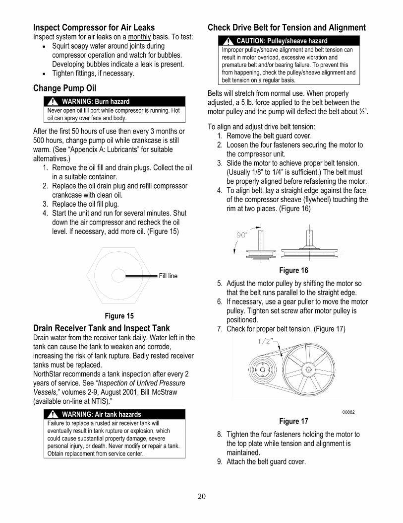
4. To align belt, lay a straight edge against the face of the compressor sheave (flywheel) touching the rim at two places. (Figure 16)
Figure 16
5. Adjust the motor pulley by shifting the motor so that the belt runs parallel to the straight edge.
6. If necessary, use a gear puller to move the motor pulley. Tighten set screw after motor pulley is positioned.
7. Check for proper belt tension. (Figure 17)
Figure 17
8. Tighten the four fasteners holding the motor to the top plate while tension and alignment is maintained.
9. Attach the belt guard cover.
Fill line
21
Keep Compressor Clean Do not allow air intakes to become blocked. If dust or debris accumulates in the compressor, clean the compressor with a damp cloth or soft bristle brush.
Note: Do not spray compressor with a garden hose or pressure washer. Water may enter the compressor and cause damage to the engine and pump.
IMPORTANT
If a part needs replacement, only use parts that meet the manufacturer’s part number specifications. Replacement parts that do not meet specifications may result in a safety hazard or poor operation of the compressor. Major service, including installation or replacement of parts, should be made by a qualified electrical service technician.
Contact NorthStar Product Support at 1-800-270-0810
for any questions, problems, or parts orders.
22
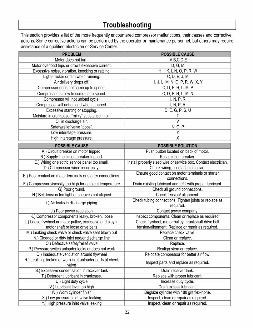
Troubleshooting
This section provides a list of the more frequently encountered compressor malfunctions, their causes and corrective actions. Some corrective actions can be performed by the operator or maintenance personnel, but others may require assistance of a qualified electrician or Service Center.
PROBLEM POSSIBLE CAUSE
Motor does not turn. A,B,C,D,E
Motor overload trips or draws excessive current. D, G, M
Excessive noise, vibration, knocking or rattling. H, I, K, L,N, O, P, R, W
Lights flicker or dim when running. C, D, E, J, M
Air delivery drops off. I, J, L, M, N, O, P, R, W, X, Y
Compressor does not come up to speed. C, D, F, H, L, M, P
Compressor is slow to come up to speed. C, D, F, H, L, M, N
Compressor will not unload cycle. I, N, P, R
Compressor will not unload when stopped. I, N, P, R
Excessive starting or stopping. D, E, G, P, S, U
Moisture in crankcase, “milky” substance in oil. T
Oil in discharge air. V
Safety/relief valve “pops”. N, O, P
Low interstage pressure. Y
High interstage pressure. X
POSSIBLE CAUSE POSSIBLE SOLUTION
A.) Circuit breaker on motor tripped. Push button located on back of motor.
B.) Supply line circuit breaker tripped. Reset circuit breaker.
C.) Wiring or electric service panel too small. Install properly sized wire or service box. Contact electrician.
D.) Compressor wired incorrectly. Check wiring, contact electrician.
E.) Poor contact on motor terminals or starter connections. Ensure good contact on motor terminals or starter
connections.
F.) Compressor viscosity too high for ambient temperature Drain existing lubricant and refill with proper lubricant.
G) Poor ground. Check all ground connections.
H.) Belt tension too tight or sheaves not aligned Check tension/ alignment.
i.) Air leaks in discharge piping Check tubing connections, Tighten joints or replace as
required.
J.) Poor power regulation Contact power company.
K.) Compressor components leaky, broken, loose Inspect components. Clean or replace as required.
L.) Loose flywheel or motor pulley, excessive end play in motor shaft or loose drive belts
Check flywheel, motor pulley, crankshaft drive belt tension/alignment. Replace or repair as required.
M.) Leaking check valve or check valve seat blown out Replace check valve.
N.) Clogged or dirty inlet and/or discharge line Clean or replace.
O.) Defective safety/relief valve Replace.
P.) Pressure switch unloader leaks or does not work Realign stem or replace.
Q.) Inadequate ventilation around flywheel Relocate compressor for better air flow.
R.) Leaking, broken or worn inlet unloader parts at check valve
Inspect parts and replace as required.
S.) Excessive condensation in receiver tank Drain receiver tank.
T.) Detergent lubricant in crankcase. Replace with proper lubricant.
U.) Light duty cycle Increase duty cycle.
V.) Lubricant level too high Drain excess lubricant.
W.) Worn cylinder finish Deglaze cylinder with 180 grit flex-hone.
X,) Low pressure inlet valve leaking Inspect, clean or repair as required.
Y.) High pressure inlet valve leaking Inspect, clean or repair as required.
23
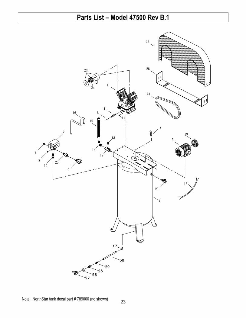
Parts List – Model 47500 Rev B.1
Note: NorthStar tank decal part # 789000 (no shown)
24
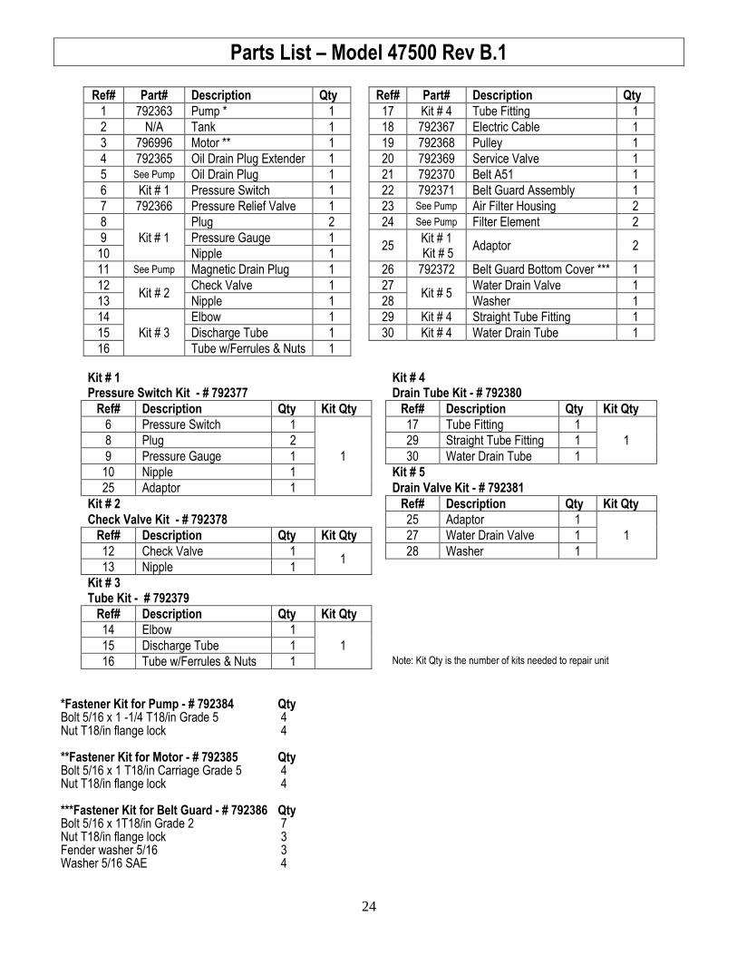
Parts List – Model 47500 Rev B.1
Ref# Part# Description Qty Ref# Part# Description Qty
1 792363 Pump * 1 17 Kit # 4 Tube Fitting 1
2 N/A Tank 1 18 792367 Electric Cable 1
3 796996 Motor ** 1 19 792368 Pulley 1
4 792365 Oil Drain Plug Extender 1 20 792369 Service Valve 1
5 See Pump Oil Drain Plug 1 21 792370 Belt A51 1
6 Kit # 1 Pressure Switch 1 22 792371 Belt Guard Assembly 1
7 792366 Pressure Relief Valve 1 23 See Pump Air Filter Housing 2
8
Kit # 1
Plug 2 24 See Pump Filter Element 2
9 Pressure Gauge 1 25
Kit # 1 Kit # 5
Adaptor 2 10 Nipple 1
11 See Pump Magnetic Drain Plug 1 26 792372 Belt Guard Bottom Cover *** 1
12 Kit # 2
Check Valve 1 27 Kit # 5
Water Drain Valve 1
13 Nipple 1 28 Washer 1
14
Kit # 3
Elbow 1 29 Kit # 4 Straight Tube Fitting 1
15 Discharge Tube 1 30 Kit # 4 Water Drain Tube 1
16 Tube w/Ferrules & Nuts 1
Kit # 1 Kit # 4 Pressure Switch Kit - # 792377 Drain Tube Kit - # 792380
Ref# Description Qty Kit Qty Ref# Description Qty Kit Qty
6 Pressure Switch 1
1
17 Tube Fitting 1
1 8 Plug 2 29 Straight Tube Fitting 1
9 Pressure Gauge 1 30 Water Drain Tube 1
10 Nipple 1 Kit # 5
25 Adaptor 1 Drain Valve Kit - # 792381
Kit # 2 Ref# Description Qty Kit Qty
Check Valve Kit - # 792378 25 Adaptor 1
1 Ref# Description Qty Kit Qty 27 Water Drain Valve 1
12 Check Valve 1 1
28 Washer 1
13 Nipple 1
Kit # 3 Tube Kit - # 792379
Ref# Description Qty Kit Qty
14 Elbow 1
1
15 Discharge Tube 1
16 Tube w/Ferrules & Nuts 1 Note: Kit Qty is the number of kits needed to repair unit
*Fastener Kit for Pump - # 792384 Qty Bolt 5/16 x 1 -1/4 T18/in Grade 5 4 Nut T18/in flange lock 4 **Fastener Kit for Motor - # 792385 Qty Bolt 5/16 x 1 T18/in Carriage Grade 5 4 Nut T18/in flange lock 4 ***Fastener Kit for Belt Guard - # 792386 Qty Bolt 5/16 x 1T18/in Grade 2 7 Nut T18/in flange lock 3 Fender washer 5/16 3 Washer 5/16 SAE 4
25
792363 Pump Exploded View
26
792363 Pump Parts List
Ref# Part# Description Qty
1 Kit # 1
Cylinder head 2
2 Allen bolt set 8
3 789354 Air filter 2
4 789355 Filter element 2
5 See part # 6
Kit # 2 Cylinder head gasket 2
6 792324 In.& ex. valve assembly 2
7 See part # 6
Kit # 2 Valve seat gasket 2
8 Kit # 3 Stud Screw 8
9 Kit # 4 Cylinder 2
10 Kit # 2 Kit # 4 Kit # 5
Cylinder gasket 2
11 792325 Kit # 4 Kit # 5
Piston ring kit 2
12 Kit # 4 Piston 2
13 792326 Rod 2
14 N/A Crankcase 1
15 788879 Oil draining plug 1
16 Kit # 2 Front cover gasket 1
17 N/A Front cover 1
18 N/A Hex bolt 4
19 788880 Oil sight gauge 1
20 789386 Oil cap 1
21 792328 Bearing 1
22 N/A Crankshaft and balancer 1
23 792329 Bearing 1
24 Kit # 2 Rear bearing seat gasket 1
25 N/A Rear bearing seat 1
26 N/A Hex bolt 4
27 Kit # 2 Oil seal 1
28 788882 Breather 1
29 789366 Pulley 1
30 Kit # 6
Fender washer 1
31 Hex bolt 1
32
Kit # 7
Exhaust elbow 1
33 Exhaust pipe 1
34 Discharge tube set 1
35 See part # 6 In.& ex. valve seat 2
36 See part # 11 Compression ring 4
37 See part # 11 Oil control ring 2
38 789384 Magnetic plug 1
* 789524 Wing nut, air filter 2
27
792363 Pump Kit List
Kit # 1 Cylinder Head and Bolt Kit - # 789336
Ref# Description Qty Kit Qty
1 Cylinder head 1 2
2 Allen bolt set 4
Kit # 2 Gasket Kit - # 789339
Ref# Description Qty Kit Qty
5 Cylinder head gasket 2
1
7 Valve seat gasket 2
10 Cylinder gasket 2
16 Front cover gasket 1
24 Rear bearing seat gasket 1
27 Oil seal 1
Kit # 3 Screw Kit - # 789358
Ref# Description Qty Kit Qty
8 Stud Screw 4 2
Kit # 4 Cylinder and Piston Kit - # 789342
Ref# Description Qty Kit Qty
9 Cylinder 1
2 10 Cylinder gasket 1
11 Piston ring kit 1
12 Piston 1
Kit # 5 Piston Ring Kit - # 789359
Ref# Description Qty Kit Qty
10 Cylinder gasket 1 2
11 Piston ring kit 1
Kit # 6 Washer and Bolt - # 789367
Ref# Description Qty Kit Qty
30 Fender washer 1 1
31 Hex bolt 1
Kit # 7 Exhaust Fitting and Tube Kit - # 792347
Ref# Description Qty Kit Qty
32 Exhaust elbow 1
1 33 Exhaust pipe 1
34 Discharge tube set 1
Note: Kit Qty is the number of kits needed to repair pump
28
Parts List – Model 47501 Rev B.1
Note: NorthStar tank decal part # 789000 (no shown)
29
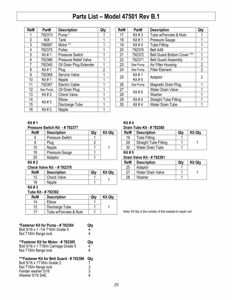
Parts List – Model 47501 Rev B.1
Ref# Part# Description Qty Ref# Part# Description Qty
1 792373 Pump * 1 17 Kit # 3 Tube w/Ferrules & Nuts 1
2 N/A Tank 1 18 Kit # 1 Pressure Gauge 1
3 796997 Motor ** 1 19 Kit # 4 Tube Fitting 1
4 792375 Pulley 1 20 792376 Belt A48 1
5 Kit # 1 Pressure Switch 1 21 792372 Belt Guard Bottom Cover *** 1
6 792366 Pressure Relief Valve 1 22 792371 Belt Guard Assembly 1
7 792340 Oil Drain Plug Extender 1 23 See Pump Air Filter Housing 2
8 Kit # 1 Plug 2 24 See Pump Filter Element 2
9 792369 Service Valve 1 25
Kit # 1 Kit # 5
Adaptor 2 10 Kit # 1 Nipple 1
11 792367 Electric Cable 1 26 See Pump Magnetic Drain Plug 1
12 See Pump Oil Drain Plug 1 27 Kit # 5
Water Drain Valve 1
13 Kit # 2 Check Valve 1 28 Washer 1
14 Kit # 3
Elbow 1 29 Kit # 4 Straight Tube Fitting 1
15 Discharge Tube 1 30 Kit # 4 Water Drain Tube 1
16 Kit # 2 Nipple 1
Kit # 1 Kit # 4 Pressure Switch Kit - # 792377 Drain Tube Kit - # 792380
Ref# Description Qty Kit Qty Ref# Description Qty Kit Qty
5 Pressure Switch 1
1
19 Tube Fitting 1
1 8 Plug 2 29 Straight Tube Fitting 1
10 Nipple 1 30 Water Drain Tube 1
18 Pressure Gauge 1 Kit # 5
25 Adaptor 1 Drain Valve Kit - # 792381
Kit # 2 Ref# Description Qty Kit Qty
Check Valve Kit - # 792378 25 Adaptor 1
1 Ref# Description Qty Kit Qty 27 Water Drain Valve 1
13 Check Valve 1 1
28 Washer 1
16 Nipple 1
Kit # 3 Tube Kit - # 792382
Ref# Description Qty Kit Qty
14 Elbow 1
1
15 Discharge Tube 1
17 Tube w/Ferrules & Nuts 1 Note: Kit Qty is the number of kits needed to repair unit
*Fastener Kit for Pump - # 792384 Qty Bolt 5/16 x 1 -1/4 T18/in Grade 5 4 Nut T18/in flange lock 4 **Fastener Kit for Motor - # 792385 Qty Bolt 5/16 x 1 T18/in Carriage Grade 5 4 Nut T18/in flange lock 4 ***Fastener Kit for Belt Guard - # 792386 Qty Bolt 5/16 x 1T18/in Grade 2 7 Nut T18/in flange lock 3 Fender washer 5/16 3 Washer 5/16 SAE 4
30
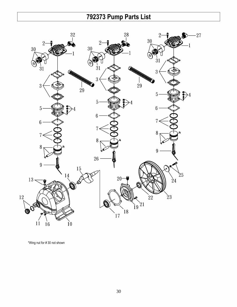
792373 Pump Parts List
*Wing nut for # 30 not shown
31
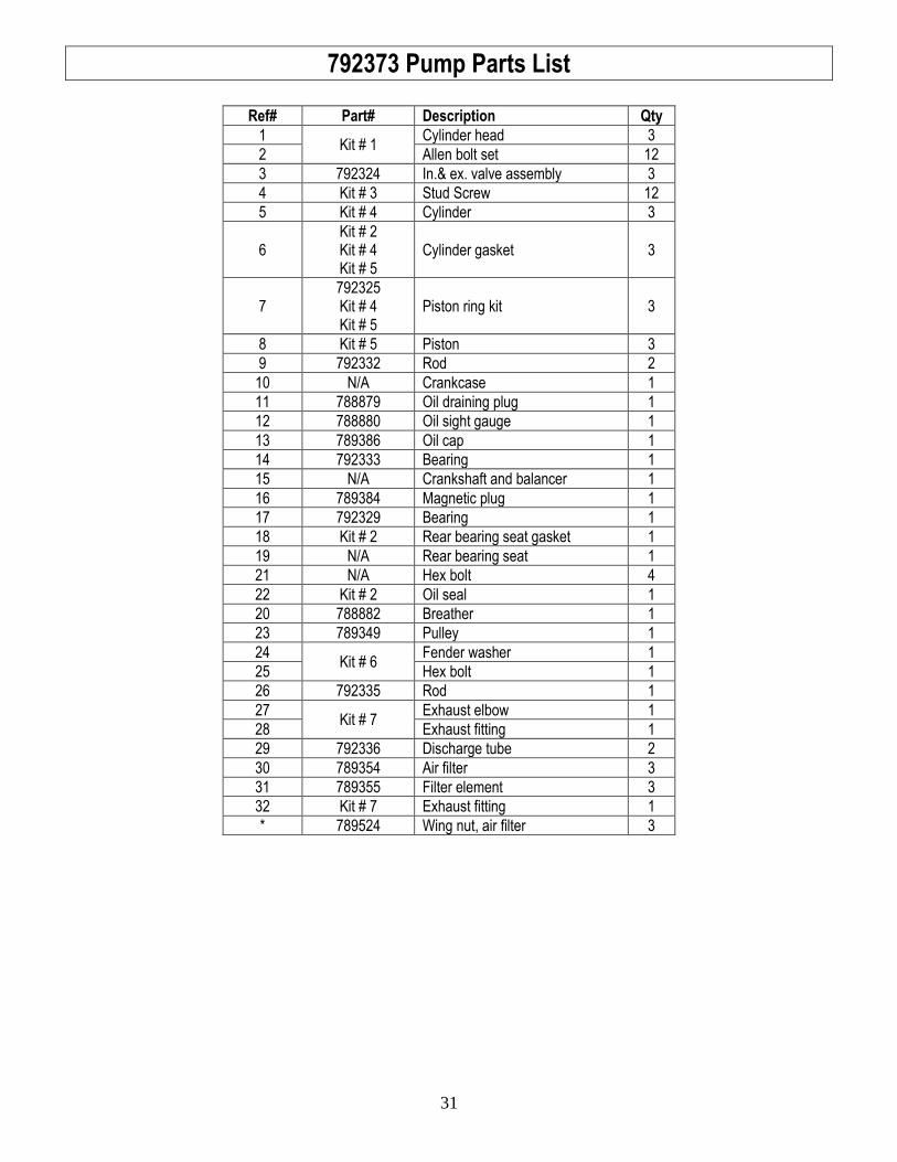
792373 Pump Parts List
Ref# Part# Description Qty
1 Kit # 1
Cylinder head 3
2 Allen bolt set 12
3 792324 In.& ex. valve assembly 3
4 Kit # 3 Stud Screw 12
5 Kit # 4 Cylinder 3
6 Kit # 2 Kit # 4 Kit # 5
Cylinder gasket 3
7 792325 Kit # 4 Kit # 5
Piston ring kit 3
8 Kit # 5 Piston 3
9 792332 Rod 2
10 N/A Crankcase 1
11 788879 Oil draining plug 1
12 788880 Oil sight gauge 1
13 789386 Oil cap 1
14 792333 Bearing 1
15 N/A Crankshaft and balancer 1
16 789384 Magnetic plug 1
17 792329 Bearing 1
18 Kit # 2 Rear bearing seat gasket 1
19 N/A Rear bearing seat 1
21 N/A Hex bolt 4
22 Kit # 2 Oil seal 1
20 788882 Breather 1
23 789349 Pulley 1
24 Kit # 6
Fender washer 1
25 Hex bolt 1
26 792335 Rod 1
27 Kit # 7
Exhaust elbow 1
28 Exhaust fitting 1
29 792336 Discharge tube 2
30 789354 Air filter 3
31 789355 Filter element 3
32 Kit # 7 Exhaust fitting 1
* 789524 Wing nut, air filter 3
32
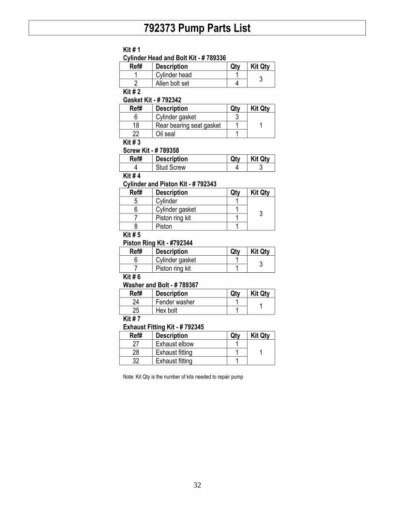
792373 Pump Parts List
Kit # 1 Cylinder Head and Bolt Kit - # 789336
Ref# Description Qty Kit Qty
1 Cylinder head 1 3
2 Allen bolt set 4
Kit # 2 Gasket Kit - # 792342
Ref# Description Qty Kit Qty
6 Cylinder gasket 3
1 18 Rear bearing seat gasket 1
22 Oil seal 1
Kit # 3 Screw Kit - # 789358
Ref# Description Qty Kit Qty
4 Stud Screw 4 3
Kit # 4 Cylinder and Piston Kit - # 792343
Ref# Description Qty Kit Qty
5 Cylinder 1
3 6 Cylinder gasket 1
7 Piston ring kit 1
8 Piston 1
Kit # 5 Piston Ring Kit - #792344
Ref# Description Qty Kit Qty
6 Cylinder gasket 1 3
7 Piston ring kit 1
Kit # 6 Washer and Bolt - # 789367
Ref# Description Qty Kit Qty
24 Fender washer 1 1
25 Hex bolt 1
Kit # 7 Exhaust Fitting Kit - # 792345
Ref# Description Qty Kit Qty
27 Exhaust elbow 1
1 28 Exhaust fitting 1
32 Exhaust fitting 1
Note: Kit Qty is the number of kits needed to repair pump
33
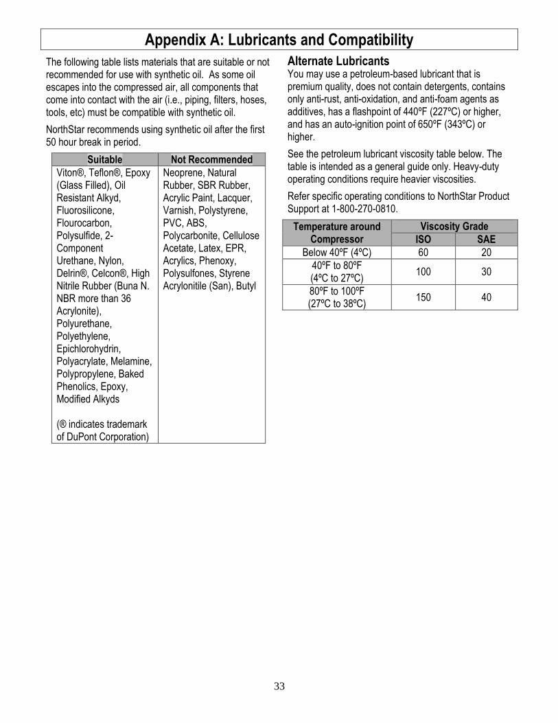
Appendix A: Lubricants and Compatibility
The following table lists materials that are suitable or not recommended for use with synthetic oil. As some oil escapes into the compressed air, all components that come into contact with the air (i.e., piping, filters, hoses, tools, etc) must be compatible with synthetic oil.
NorthStar recommends using synthetic oil after the first 50 hour break in period.
Suitable Not Recommended
Viton®, Teflon®, Epoxy (Glass Filled), Oil Resistant Alkyd, Fluorosilicone, Flourocarbon, Polysulfide, 2-Component Urethane, Nylon, Delrin®, Celcon®, High Nitrile Rubber (Buna N. NBR more than 36 Acrylonite), Polyurethane, Polyethylene, Epichlorohydrin, Polyacrylate, Melamine, Polypropylene, Baked Phenolics, Epoxy, Modified Alkyds (® indicates trademark of DuPont Corporation)
Neoprene, Natural Rubber, SBR Rubber, Acrylic Paint, Lacquer, Varnish, Polystyrene, PVC, ABS, Polycarbonite, Cellulose Acetate, Latex, EPR, Acrylics, Phenoxy, Polysulfones, Styrene Acrylonitile (San), Butyl
Alternate Lubricants You may use a petroleum-based lubricant that is premium quality, does not contain detergents, contains only anti-rust, anti-oxidation, and anti-foam agents as additives, has a flashpoint of 440ºF (227ºC) or higher, and has an auto-ignition point of 650ºF (343ºC) or higher.
See the petroleum lubricant viscosity table below. The table is intended as a general guide only. Heavy-duty operating conditions require heavier viscosities.
Refer specific operating conditions to NorthStar Product Support at 1-800-270-0810.
Temperature around Compressor
Viscosity Grade
ISO SAE
Below 40ºF (4ºC) 60 20
40ºF to 80ºF (4ºC to 27ºC)
100 30
80ºF to 100ºF (27ºC to 38ºC)
150 40
34
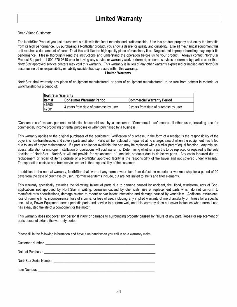
Limited Warranty
Dear Valued Customer: The NorthStar Product you just purchased is built with the finest material and craftsmanship. Use this product properly and enjoy the benefits from its high performance. By purchasing a NorthStar product, you show a desire for quality and durability. Like all mechanical equipment this unit requires a due amount of care. Treat this unit like the high quality piece of machinery it is. Neglect and improper handling may impair its performance. Please thoroughly read the instructions and understand the operation before using your product. Always contact NorthStar Product Support at 1-800-270-0810 prior to having any service or warranty work performed, as some services performed by parties other than NorthStar approved service centers may void this warranty. This warranty is in lieu of any other warranty expressed or implied and NorthStar assumes no other responsibility or liability outside that expressed within this warranty.
Limited Warranty
NorthStar shall warranty any piece of equipment manufactured, or parts of equipment manufactured, to be free from defects in material or workmanship for a period of:
NorthStar Warranty
Item # Consumer Warranty Period Commercial Warranty Period
47500 47501
4 years from date of purchase by user 2 years from date of purchase by user
“Consumer use” means personal residential household use by a consumer. “Commercial use” means all other uses, including use for commercial, income producing or rental purposes or when purchased by a business. This warranty applies to the original purchaser of the equipment (verification of purchase, in the form of a receipt, is the responsibility of the buyer), is non-transferable, and covers parts and labor. Parts will be replaced or repaired at no charge, except when the equipment has failed due to lack of proper maintenance. If a part is no longer available, the part may be replaced with a similar part of equal function. Any misuse, abuse, alteration or improper installation or operations will void warranty. Determining whether a part is to be replaced or repaired is the sole decision of NorthStar. NorthStar will not provide for replacement of complete products due to defective parts. Any costs incurred due to replacement or repair of items outside of a NorthStar approved facility is the responsibility of the buyer and not covered under warranty. Transportation costs to and from service center is the responsibility of the customer. In addition to the normal warranty, NorthStar shall warrant any normal wear item from defects in material or workmanship for a period of 90 days from the date of purchase by user. Normal wear items include, but are not limited to, belts and filter elements. This warranty specifically excludes the following; failure of parts due to damage caused by accident, fire, flood, windstorm, acts of God, applications not approved by NorthStar in writing, corrosion caused by chemicals, use of replacement parts which do not conform to manufacturer’s specifications, damage related to rodent and/or insect infestation and damage caused by vandalism. Additional exclusions: loss of running time, inconvenience, loss of income, or loss of use, including any implied warranty of merchantability of fitness for a specific use. Also, Power Equipment needs periodic parts and service to perform well, and this warranty does not cover instances when normal use has exhausted the life of a component or the motor. This warranty does not cover any personal injury or damage to surrounding property caused by failure of any part. Repair or replacement of parts does not extend the warranty period. Please fill in the following information and have it on hand when you call in on a warranty claim. Customer Number: ______________________________________________________________ Date of Purchase: _______________________________________________________________ NorthStar Serial Number: _________________________________________________________ Item Number: __________________________________________________________________

35
This page left intentionally blank

36
Assembled by Northern Tool & Equipment Company, Inc.
Burnsville, MN 55306 NorthernTool.com