product description - transtec...oceanstor 5300 v3&5500 v3&5600 v3&5800 v3&6800 v3...
TRANSCRIPT
OceanStor 5300 V3&5500 V3&5600 V3&5800V3&6800 V3 Storage SystemV300R003
Product Description
Issue 05
Date 2016-11-20
HUAWEI TECHNOLOGIES CO., LTD.
Copyright © Huawei Technologies Co., Ltd. 2016. All rights reserved.No part of this document may be reproduced or transmitted in any form or by any means without prior writtenconsent of Huawei Technologies Co., Ltd. Trademarks and Permissions
and other Huawei trademarks are trademarks of Huawei Technologies Co., Ltd.All other trademarks and trade names mentioned in this document are the property of their respectiveholders. NoticeThe purchased products, services and features are stipulated by the contract made between Huawei and thecustomer. All or part of the products, services and features described in this document may not be within thepurchase scope or the usage scope. Unless otherwise specified in the contract, all statements, information,and recommendations in this document are provided "AS IS" without warranties, guarantees orrepresentations of any kind, either express or implied.
The information in this document is subject to change without notice. Every effort has been made in thepreparation of this document to ensure accuracy of the contents, but all statements, information, andrecommendations in this document do not constitute a warranty of any kind, express or implied.
Huawei Technologies Co., Ltd.Address: Huawei Industrial Base
Bantian, LonggangShenzhen 518129People's Republic of China
Website: http://e.huawei.com
Issue 05 (2016-11-20) Huawei Proprietary and ConfidentialCopyright © Huawei Technologies Co., Ltd.
i
About This Document
PurposeThis document describes the orientation, features, architecture, technical specifications,product configuration, environment requirements, standard compliance and grantedcertifications of the OceanStor 5300 V3/5500 V3/5600 V3/5800 V3/6800 V3 storage system.
Intended AudienceThis document is intended for: All readers
Symbol ConventionsThe symbols that may be found in this document are defined as follows.
Symbol Description
DANGERIndicates an imminently hazardous situation which, if notavoided, will result in death or serious injury.
WARNINGIndicates a potentially hazardous situation which, if notavoided, could result in death or serious injury.
Indicates a potentially hazardous situation which, if notavoided, may result in minor or moderate injury.
Indicates a potentially hazardous situation which, if notavoided, could result in equipment damage, data loss,performance deterioration, or unanticipated results.NOTICE is used to address practices not related topersonal injury.
OceanStor 5300 V3&5500 V3&5600 V3&5800 V3&6800V3 Storage SystemProduct Description About This Document
Issue 05 (2016-11-20) Huawei Proprietary and ConfidentialCopyright © Huawei Technologies Co., Ltd.
ii
Symbol Description
NOTE Calls attention to important information, best practices andtips.NOTE is used to address information not related topersonal injury, equipment damage, and environmentdeterioration.
Change HistoryChanges between document issues are cumulative. The latest document issue contains all thechanges made in earlier issues.
Issue 05 (2016-11-20)
This issue is the fifth official release.
l Added specifications of V300R003C20.
l Added the description of vibration and impact parameters.
Issue 04 (2016-07-25)
This issue is the fourth official release.
Made minor changes in specifications.
Issue 03 (2016-04-30)
This issue is the third official release.
l Added the information that a SmartIO module in FCoE mode only supports networkingthrough FCoE switches.
l Added the information that you are not advised to use an FCoE interface module foriSCSI and FCoE protocols at the same time.
l Added sorting rules for disks in a high-density disk enclosure.
Issue 02 (2015-12-10)
This issue is the second official release.
Add HyperVault feature. Made minor changes in specifications.
Issue 01 (2015-08-30)
This issue is the first official release.
OceanStor 5300 V3&5500 V3&5600 V3&5800 V3&6800V3 Storage SystemProduct Description About This Document
Issue 05 (2016-11-20) Huawei Proprietary and ConfidentialCopyright © Huawei Technologies Co., Ltd.
iii
Contents
About This Document.....................................................................................................................ii
1 Product Positioning.......................................................................................................................1
2 Product Features.............................................................................................................................3
3 Typical Applications.....................................................................................................................93.1 High-Performance Applications................................................................................................................................... 103.2 High-Availability Applications.....................................................................................................................................113.3 High-Density and Multi-Service Applications............................................................................................................. 13
4 Hardware Architecture............................................................................................................... 174.1 Device Composition..................................................................................................................................................... 194.2 2 U Controller Enclosure..............................................................................................................................................194.2.1 Overview................................................................................................................................................................... 194.2.2 Component Description.............................................................................................................................................234.2.2.1 System Enclosure................................................................................................................................................... 234.2.2.2 Controller................................................................................................................................................................244.2.2.3 16 Gbit/s Fibre Channel Interface Module............................................................................................................. 274.2.2.4 8 Gbit/s Fibre Channel Interface Module............................................................................................................... 294.2.2.5 10 Gbit/s FCoE Interface Module (Two Ports).......................................................................................................314.2.2.6 10GE Electrical Interface Module..........................................................................................................................324.2.2.7 GE Electrical Interface Module..............................................................................................................................344.2.2.8 10 Gbit/s TOE Interface Module............................................................................................................................ 364.2.2.9 10 Gbit/s FCoE Interface Module (Four Ports)...................................................................................................... 374.2.2.10 56 Gbit/s IB Interface Module..............................................................................................................................394.2.2.11 SmartIO Interface Module.................................................................................................................................... 404.2.2.12 Smart ACC Module (Applicable to V300R003C00/V300R003C10).................................................................. 424.2.2.13 High-Density 8 Gbit/s Fibre Channel Interface Module...................................................................................... 434.2.2.14 12 Gbit/s SAS Expansion Module........................................................................................................................454.2.2.15 Power-BBU Module............................................................................................................................................. 474.2.2.16 Disk Module......................................................................................................................................................... 514.2.3 Indicator Introduction................................................................................................................................................ 534.3 3 U Controller Enclosure..............................................................................................................................................574.3.1 Overview................................................................................................................................................................... 574.3.2 Component Description.............................................................................................................................................60
OceanStor 5300 V3&5500 V3&5600 V3&5800 V3&6800V3 Storage SystemProduct Description Contents
Issue 05 (2016-11-20) Huawei Proprietary and ConfidentialCopyright © Huawei Technologies Co., Ltd.
iv
4.3.2.1 System Enclosure................................................................................................................................................... 604.3.2.2 Controller................................................................................................................................................................614.3.2.3 Fan Module.............................................................................................................................................................624.3.2.4 BBU........................................................................................................................................................................ 644.3.2.5 16 Gbit/s Fibre Channel Interface Module............................................................................................................. 654.3.2.6 8 Gbit/s Fibre Channel Interface Module............................................................................................................... 674.3.2.7 10 Gbit/s FCoE Interface Module (Two Ports).......................................................................................................694.3.2.8 10GE Electrical Interface Module..........................................................................................................................704.3.2.9 GE Electrical Interface Module..............................................................................................................................724.3.2.10 10 Gbit/s FCoE Interface Module (Four Ports).................................................................................................... 744.3.2.11 10 Gbit/s TOE Interface Module.......................................................................................................................... 754.3.2.12 56 Gbit/s IB Interface Module..............................................................................................................................774.3.2.13 SmartIO Interface Module....................................................................................................................................784.3.2.14 Smart ACC Module (Applicable to V300R003C00/V300R003C10).................................................................. 804.3.2.15 High-Density 8 Gbit/s Fibre Channel Interface Module...................................................................................... 814.3.2.16 12 Gbit/s SAS Expansion Module........................................................................................................................834.3.2.17 Management Module............................................................................................................................................854.3.2.18 Power Module.......................................................................................................................................................864.3.3 Indicator Introduction................................................................................................................................................ 874.4 6 U Controller Enclosure..............................................................................................................................................924.4.1 Overview................................................................................................................................................................... 924.4.2 Component Description.............................................................................................................................................954.4.2.1 System Enclosure................................................................................................................................................... 954.4.2.2 Controller................................................................................................................................................................964.4.2.3 Fan Module.............................................................................................................................................................984.4.2.4 BBU........................................................................................................................................................................ 994.4.2.5 16 Gbit/s Fibre Channel Interface Module........................................................................................................... 1014.4.2.6 8 Gbit/s Fibre Channel Interface Module............................................................................................................. 1034.4.2.7 10 Gbit/s FCoE Interface Module (Two Ports).....................................................................................................1054.4.2.8 10GE Electrical Interface Module........................................................................................................................1064.4.2.9 GE Electrical Interface Module............................................................................................................................1084.4.2.10 10 Gbit/s TOE Interface Module........................................................................................................................ 1104.4.2.11 10 Gbit/s FCoE Interface Module (Four Ports).................................................................................................. 1114.4.2.12 56 Gbit/s IB Interface Module............................................................................................................................ 1134.4.2.13 SmartIO Interface Module.................................................................................................................................. 1144.4.2.14 Smart ACC Module (Applicable to V300R003C00/V300R003C10)................................................................ 1164.4.2.15 High-Density 8 Gbit/s Fibre Channel Interface Module.................................................................................... 1174.4.2.16 12 Gbit/s SAS Expansion Module...................................................................................................................... 1194.4.2.17 Management Module..........................................................................................................................................1214.4.2.18 Power Module.....................................................................................................................................................1224.4.3 Indicator Introduction.............................................................................................................................................. 1234.5 2 U Disk Enclosure (2.5-Inch Disks)..........................................................................................................................128
OceanStor 5300 V3&5500 V3&5600 V3&5800 V3&6800V3 Storage SystemProduct Description Contents
Issue 05 (2016-11-20) Huawei Proprietary and ConfidentialCopyright © Huawei Technologies Co., Ltd.
v
4.5.1 Overview................................................................................................................................................................. 1284.5.2 Component Description...........................................................................................................................................1304.5.2.1 System Enclosure................................................................................................................................................. 1304.5.2.2 Expansion Module................................................................................................................................................1314.5.2.3 Power Module.......................................................................................................................................................1334.5.2.4 Disk Module......................................................................................................................................................... 1354.5.3 Indicator Introduction.............................................................................................................................................. 1364.6 4 U Disk Enclosure (3.5-Inch Disks)..........................................................................................................................1384.6.1 Overview................................................................................................................................................................. 1394.6.2 Component Description...........................................................................................................................................1414.6.2.1 System Enclosure................................................................................................................................................. 1414.6.2.2 Expansion Module................................................................................................................................................1424.6.2.3 Power Module.......................................................................................................................................................1434.6.2.4 Fan Module...........................................................................................................................................................1464.6.2.5 Disk Module......................................................................................................................................................... 1464.6.3 Indicator Introduction.............................................................................................................................................. 1484.7 High-Density Disk Enclosure.....................................................................................................................................1504.7.1 Overview................................................................................................................................................................. 1514.7.2 Component Description...........................................................................................................................................1544.7.2.1 System Enclosure................................................................................................................................................. 1544.7.2.2 Expansion Module................................................................................................................................................1544.7.2.3 Disk Module......................................................................................................................................................... 1564.7.2.4 Power Module.......................................................................................................................................................1574.7.2.5 Fan Module...........................................................................................................................................................1584.7.3 Indicator Introduction.............................................................................................................................................. 1594.8 (optional) Data Switch................................................................................................................................................1624.9 Device Cables............................................................................................................................................................. 1644.9.1 Power Cables........................................................................................................................................................... 1644.9.2 Ground Cables......................................................................................................................................................... 1654.9.3 Network Cables....................................................................................................................................................... 1654.9.4 Serial Cables............................................................................................................................................................ 1664.9.5 Mini SAS HD Cables.............................................................................................................................................. 1664.9.5.1 Mini SAS HD Electrical Cables........................................................................................................................... 1664.9.5.2 Mini SAS HD optical cables................................................................................................................................ 1674.9.6 Optical Fibers.......................................................................................................................................................... 1684.9.7 FDR Cables..............................................................................................................................................................1684.9.8 MPO-4*DLC Fiber..................................................................................................................................................169
5 Software Architecture............................................................................................................... 170
6 Product Specifications.............................................................................................................. 1786.1 Hardware Specifications.............................................................................................................................................1796.2 Software Specifications.............................................................................................................................................. 190
OceanStor 5300 V3&5500 V3&5600 V3&5800 V3&6800V3 Storage SystemProduct Description Contents
Issue 05 (2016-11-20) Huawei Proprietary and ConfidentialCopyright © Huawei Technologies Co., Ltd.
vi
7 Environmental Requirements................................................................................................. 2097.1 Temperature, Humidity, and Altitude......................................................................................................................... 2107.2 Vibration and Shock....................................................................................................................................................2117.3 Particle Contaminants................................................................................................................................................. 2117.4 Corrosive Airborne Contaminants..............................................................................................................................2127.5 Heat Dissipation and Noise........................................................................................................................................ 215
8 Standards Compliance..............................................................................................................218
9 Certifications.............................................................................................................................. 223
10 Operation and Maintenance..................................................................................................226
A How to Obtain Help.................................................................................................................228A.1 Preparations for Contacting Huawei..........................................................................................................................229A.1.1 Collecting Troubleshooting Information................................................................................................................ 229A.1.2 Making Debugging Preparations............................................................................................................................ 229A.2 How to Use the Document.........................................................................................................................................229A.3 How to Obtain Help from Website............................................................................................................................ 229A.4 Ways to Contact Huawei............................................................................................................................................230
B Glossary...................................................................................................................................... 231
C Acronyms and Abbreviations................................................................................................ 243
OceanStor 5300 V3&5500 V3&5600 V3&5800 V3&6800V3 Storage SystemProduct Description Contents
Issue 05 (2016-11-20) Huawei Proprietary and ConfidentialCopyright © Huawei Technologies Co., Ltd.
vii
1 Product Positioning
The OceanStor 5300 V3/5500 V3/5600 V3/5800 V3/6800 V3 are mid-range and high-endstorage products newly developed by Huawei Technologies Co., Ltd (Huawei for short). Thisseries is ideal for processing existing storage applications and follows the future developmenttrend of storage technologies. It meets medium- and large-sized enterprises' storagerequirements for mass data storage, speed data access, high availability, high utilization,energy saving, and ease-of-use.
Business development leads to a great amount of service data, which poses ever high demandson storage systems. Traditional storage systems fail to meet these demands and encounter thefollowing bottlenecks: inflexible storage performance expansion, complex management ofvarious devices, failure to utilize legacy devices, and increasing maintenance costs occupyinga large part of Total Cost of Ownership (TCO). To eliminate these bottlenecks, Huawei haslaunched the OceanStor 5300 V3/5500 V3/5600 V3/5800 V3/6800 V3 storage system.
The OceanStor 5300 V3/5500 V3/5600 V3/5800 V3/6800 V3 storage system offerscomprehensive and superb solutions by providing industry-leading performance, diverseefficiency boost mechanisms, as well as file-level and block-level data storage and variousstorage protocols on a single platform. Those solutions help customers maximize their returnon investment (ROI) and meet the requirements of different application scenarios such asOnline Transaction Processing (OLTP) and Online Analytical Processing (OLAP) of largedatabases, high-performance computing (HPC), digital media, Internet operation, centralizedstorage, backup, disaster recovery, and data migration.
In addition to providing high-performance storage services for application servers, OceanStor5300 V3/5500 V3/5600 V3/5800 V3/6800 V3 storage system supports advanced data backupand disaster recovery technologies, ensuring the secure and smooth running of data services.Also, OceanStor 5300 V3/5500 V3/5600 V3/5800 V3/6800 V3 storage system offers easy-to-use management modes and convenient local/remote maintenance modes, greatly decreasingthe management and maintenance costs.
Position and Application of the Storage System on an Integrated NAS and SANNetwork
Figure 1-1 shows the position and application of the storage system on an integrated NASand SAN network.
OceanStor 5300 V3&5500 V3&5600 V3&5800 V3&6800V3 Storage SystemProduct Description 1 Product Positioning
Issue 05 (2016-11-20) Huawei Proprietary and ConfidentialCopyright © Huawei Technologies Co., Ltd.
1
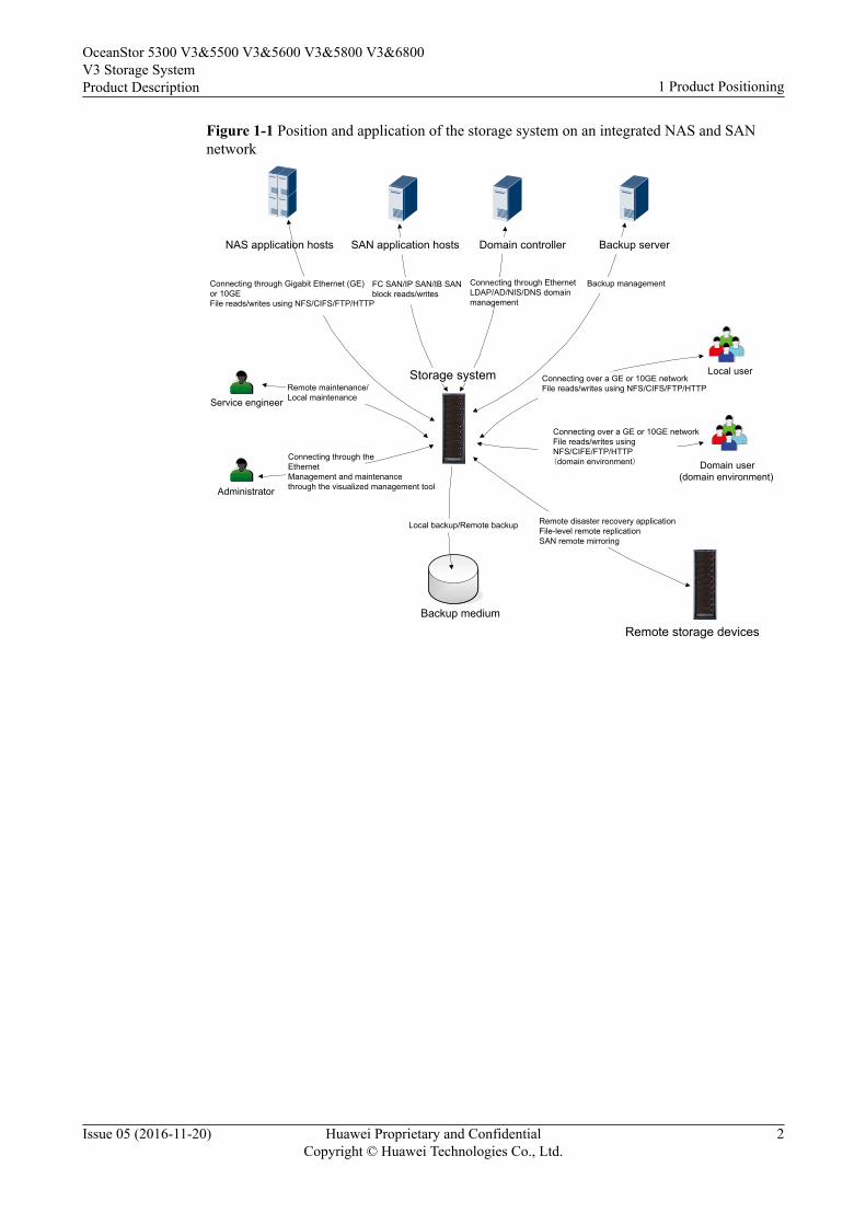
Figure 1-1 Position and application of the storage system on an integrated NAS and SANnetwork
FC SAN/IP SAN/IB SAN block reads/writes
Connecting through the EthernetManagement and maintenance through the visualized management tool
Backup medium
Local backup/Remote backup
Domain user(domain environment)
Local user
Administrator
Service engineer
Domain controller
Connecting through Ethernet LDAP/AD/NIS/DNS domain management
Backup server
Backup management
NAS application hosts
Storage systemRemote maintenance/Local maintenance
Connecting through Gigabit Ethernet (GE) or 10GEFile reads/writes using NFS/CIFS/FTP/HTTP
Remote storage devices
SAN application hosts
Connecting over a GE or 10GE networkFile reads/writes using NFS/CIFS/FTP/HTTP
Connecting over a GE or 10GE networkFile reads/writes using NFS/CIFE/FTP/HTTP(domain environment)
Remote disaster recovery applicationFile-level remote replicationSAN remote mirroring
OceanStor 5300 V3&5500 V3&5600 V3&5800 V3&6800V3 Storage SystemProduct Description 1 Product Positioning
Issue 05 (2016-11-20) Huawei Proprietary and ConfidentialCopyright © Huawei Technologies Co., Ltd.
2
2 Product Features
Powered by a superior hardware structure, an integrated block and file software architecture,as well as advanced data applications and protection technologies, the OceanStor 5300V3/5500 V3/5600 V3/5800 V3/6800 V3 storage system provides high performance, superbscalability, robust reliability, and high availability, meeting medium- and large-sizedenterprises' different storage requirements.
Unified Storagel Support for SAN and NAS storage technologies
The OceanStor 5300 V3/5500 V3/5600 V3/5800 V3/6800 V3 storage system unifiedstorage system that supports both SAN and NAS storage technologies is able to storestructured and unstructured data.
l Support for mainstream storage protocolsThe OceanStor 5300 V3/5500 V3/5600 V3/5800 V3/6800 V3 storage system supportsmainstream storage protocols such as iSCSI, Fibre Channel, NFS, CIFS, HTTP and FTP.
High PerformanceThe OceanStor 5300 V3/5500 V3/5600 V3/5800 V3/6800 V3 storage system offers a three-level performance acceleration technology, and delivers hierarchical performance for differentapplications. The three levels are:
1. Superior hardwareThe OceanStor 5300 V3/5500 V3/5600 V3/5800 V3/6800 V3 storage system is equippedwith 64-bit multi-core processors, high-speed and large-capacity caches, and varioushigh-speed interface modules. The superior hardware allows the OceanStor 5300V3/5500 V3/5600 V3/5800 V3/6800 V3 storage system to offer better storageperformance than tradition storage systems.
2. SmartTierThe SmartTier technology identifies hotspot data and periodically promotes them tohigh-performance storage medium for a performance boost. In addition, SmartTiersupports SSD data caching, accelerating access to hotspot data.
3. Solid state drives (SSDs)The OceanStor 5300 V3/5500 V3/5600 V3/5800 V3/6800 V3 storage system can befully configured with SSDs to provide peak performance for the most-demandingapplications.
OceanStor 5300 V3&5500 V3&5600 V3&5800 V3&6800V3 Storage SystemProduct Description 2 Product Features
Issue 05 (2016-11-20) Huawei Proprietary and ConfidentialCopyright © Huawei Technologies Co., Ltd.
3
In addition, users can insert external acceleration modules into the storage system for highersystem performance. For example, inserting Smart ACC modules improves systemdeduplication and compression performance while reducing CPU usage.
Flexible Scalability
The OceanStor 5300 V3/5500 V3/5600 V3/5800 V3/6800 V3 storage system has anoutstanding scalability. It supports various types of disks and host interface modules. Also, theinterface modules have a high density. The supported multiple types and high-densityinterface modules bring a high system scalability.
The OceanStor 5300 V3/5500 V3/5600 V3/5800 V3/6800 V3 storage system supports thefollowing types of disks and interface modules:l Types of disks:
SAS disks, NL-SAS disks, and SSDs.l Types of host interface modules:
8 Gbit/s fiber channel, 16 Gbit/s fiber channel, GE, 10 Gbit/s TOE, 10GE, 10 Gbit/sFCoE, 56 Gbit/s(4*14 Gbit/s) IB and SmartIO.
The OceanStor 5300 V3/5500 V3/5600 V3/5800 V3/6800 V3 storage system also supportsScale-out expansion of clustered nodes for system performance improvement.
Proven Reliability
The OceanStor 5300 V3/5500 V3/5600 V3/5800 V3/6800 V3 storage system offers protectionmeasures against component failures and power failure, and uses advanced technologies tominimize risks of disk failures and data loss. This ensures the proven reliability of the storagesystem.
l Against component failuresThe storage system components are in 1+1 redundancy and work in active-active mode.Normally, every two components are working simultaneously and share loads. If onecomponent fails or gets offline, the other one takes over all loads and speeds up tocompensate. The whole process is transparent to applications.
l RAID 2.0+ underlying virtualizationThe storage system employs innovative RAID 2.0+ underlying virtualization technologyfor automatic disk load balancing. If a disk encounters a fault, all the other disks in thesame disk domain help construct the faulty disk's service data, achieving a 20-fold fasterreconstruction speed than traditional RAID technology. In addition, RAID 2.0+significantly reduces the possibility of multi-disk failure.
l Against unexpected downtimeThe storage system is equipped with backup battery modules (BBUs) that provide powerfor the controller enclosure in the event of a power failure. This protects the data in thecache and dumps it to the build-in disks of the controllers to avoid data loss.
l Bad sector repairThe storage system is prone to bad sectors of disks. The OceanStor 5300 V3/5500V3/5600 V3/5800 V3/6800 V3 storage system adopts the bad sector repair technology toproactively detect and repair bad sectors, reduce the disk failure rate by 50%, andprolong the service life of disks.
l Disk pre-copy
OceanStor 5300 V3&5500 V3&5600 V3&5800 V3&6800V3 Storage SystemProduct Description 2 Product Features
Issue 05 (2016-11-20) Huawei Proprietary and ConfidentialCopyright © Huawei Technologies Co., Ltd.
4
The disk pre-copy technology enables the storage system to routinely check the hardwarestatus and migrate data from any failing disk to minimize the risks of data loss.
l IP address floatingThe storage system adopts IP address floating technology. If a physical host port thatimplements the NAS protocol is damaged, the IP address assigned to that portautomatically floats to another functional port. Based on the correct networking, servicesare seamlessly switched over, preventing damage to a port from affecting services.
High AvailabilityThe OceanStor 5300 V3/5500 V3/5600 V3/5800 V3/6800 V3 storage system usesTurboModule, online capacity expansion, and disk roaming technologies to provide highavailability for applications and nonstop system running during maintenance. The functions ofTurboModule, online capacity expansion, and disk roaming are as follows:l TurboModule enables controllers, fans, power modules, interface modules, BBUs, and
disks to be hot-swapped without restarting the storage system, allowing onlineoperations.
l Dynamic capacity expansion enables users to add disks to a disk domain in an online andeasy manner.
l Disk roaming enables a storage system to automatically identify relocated disks andresume their services.
The OceanStor 5300 V3/5500 V3/5600 V3/5800 V3/6800 V3 storage system providesmultiple advanced data protection technologies to protect data integrity and continuoussystem running even when catastrophic disasters happen. Advanced data protectiontechnologies of the OceanStor 5300 V3/5500 V3/5600 V3/5800 V3/6800 V3 storage systemare snapshot, LUN copy, remote replication, clone and HyperMirror:l Snapshot generates multiple point-in-time images for the source LUN (Logical Unit
Number) or source file system data. The snapshot images can be used to recover dataquickly when needed.
l LUN copy backs up data among heterogeneous storage systems for data protection.l Remote replication backs up local data onto a remote storage system for disaster
recovery.l Clone preserves a real-time physical copy of a source LUN for the high availability of
local data.l HyperMirror backs up data in real time. If the source data becomes unavailable,
applications can automatically use the data copy, ensuring high data security andapplication continuity.
In addition, the system supports Network Data Management Protocol (NDMP) for databackup and recovery.
The OceanStor 5300 V3/5500 V3/5600 V3/5800 V3/6800 V3 storage system employsmultiple resource application technologies and provides flexible resource management toprotect customers' storage investments. The resource application technologies includeSmartVirtualization, SmartMigration, and SmartMulti-Tenant.l SmartVirtualization enables a local storage system to centrally manage storage resources
of third-party storage systems, simplifying storage system management and reducingmaintenance costs.
l SmartMigration migrates LUNs in or between storage systems, adjusting and allocatingresources along with business development.
OceanStor 5300 V3&5500 V3&5600 V3&5800 V3&6800V3 Storage SystemProduct Description 2 Product Features
Issue 05 (2016-11-20) Huawei Proprietary and ConfidentialCopyright © Huawei Technologies Co., Ltd.
5
l SmartMulti-Tenant enables a storage system to provide different tenants with sharedstorage resources and to separate tenant access and management.
The OceanStor 5300 V3/5500 V3/5600 V3/5800 V3/6800 V3 storage system supportsmemory upgrade so that storage performance matches service development.
High System Security
Storage Network Security
l Security of management channels
The management operations from physical ports are controlled by the accessauthentication mechanism of the storage system, and only authorized users are allowedto manage the storage system.
l Anti-attack protection for protocols and ports
The storage system provides only necessary ports to the external for system operationsand maintenance. All the ports used are listed in the Communication Matrix. Dynamiclistening ports are functioning in the proper scope, and no unopened port exists.
l Service ports are isolated from management ports
The Access Control List (ACL) mechanism is adopted to isolate Ethernet ports frominternal heartbeat network ports, management network ports, and maintenance networkports.
NOTE
Internal heartbeat links are established between controllers for these controllers to detect eachother's working status. You do not need to separately connect cables.
Storage Service Security
l Security of the operating system
The storage system uses a dedicated operating system. Security of the operating systemhas been hardened before the storage system is delivered. The storage systems updatesecurity patches for their operating systems and open-source software based on siterequirements, safeguarding users' data.
l Data storage encryption
– The storage system supports data encryption by using a network password manager.The network password manager employs the standard cryptographic algorithmsupported by the State Encryption Administration of China. It allows only the hoststhat comply with security policies to access storage system data by auditing accesscontrol policies and controlling access attempts from hosts. After the networkpassword manager is deployed, all mutual information between the hosts andstorage system will pass the network password manager to enable read/write dataencryption and decryption and ensure data security of the storage system.
– The storage system supports disk encryption. The hardware circuits and internaldata encrypt key of disks are used for data writing encryption and data readingdecryption. To ensure the security of data encrypt key, the storage system and thethird-party key management server jointly provide a highly secure, reliable, andavailable key management solution.
l Data sanitation
When deleting unwanted data, the system erases the specified LUN to make the deleteddata unable to be restored, preventing critical data leaks.
OceanStor 5300 V3&5500 V3&5600 V3&5800 V3&6800V3 Storage SystemProduct Description 2 Product Features
Issue 05 (2016-11-20) Huawei Proprietary and ConfidentialCopyright © Huawei Technologies Co., Ltd.
6
l File antivirusWhen the storage system runs a file system and shares the file system with clientsthrough CIFS, third-party antivirus software can be used to trigger virus scanning anddelete virus-infected files, improving storage system security.
Storage Management Securityl Security of management and maintenance
The operations of users can be allowed and denied. All management operations arelogged by the system.
l Data integrity protection and tamper resistanceThe write once read many (WORM) feature allows users to set critical data to read-onlystate, preventing unauthorized data change and deletion during a specified period oftime.
Virtualization, Intelligence, and EfficiencyThe OceanStor 5300 V3/5500 V3/5600 V3/5800 V3/6800 V3 storage system absorbs theconcept of "Virtualization, Intelligence, and Efficiency", which fits the up-to-date storagedesign idea and wins a leading position for the storage system. Compared with traditionalstorage systems, the OceanStor 5300 V3/5500 V3/5600 V3/5800 V3/6800 V3 storage systemachieves a higher storage space usage, faster data reconstruction speed, smarter performanceallocation technology, and finer service quality control. To obtain the previous achievements,the following technologies contribute:l RAID 2.0+ underlying virtualization
RAID 2.0+ underlying virtualization technology divides disk storage space into small-sized data blocks and uses the blocks to create RAID groups for fine-grained resourcemanagement. The technology realizes automatic load balancing, higher storageperformance, better storage space utilization, faster disk reconstruction, and delicatestorage space management. RAID 2.0+ serves as a basis for a number of other advancedstorage technologies.
l SmartTier (intelligent storage tiering)Enables a storage system to automatically analyze data access frequency per unit timeand relocate data to disks of different performance levels based on the analysis result.(High-performance disks store hot data, performance disks store warm data, and large-capacity disks store cold data.) In this way, the optimal overall performance is achievedand the per IOPS cost is reduced.
l SmartQoS (intelligent service quality control)Enables a storage system to categorize service data based on data characteristics (eachcategory represents a type of application) and set a priority and performance objectivefor each category. In this way, resources are provided for services properly, ensuringmission-critical services' performance.
l Thin provisioningAllows on-demand allocation of storage space rather than the traditional method of pre-allocating all storage space at the initial stage. It is more efficient because the amount ofresources used is close to the amount of resources allocated. In this way, the initialpurchase cost and total cost of ownership are reduced.
l SmartCache (intelligent storage cache)Uses SSDs as cache resources to significantly promote system read performance whenrandom, small I/Os with hot data require more read operations than write operations.
OceanStor 5300 V3&5500 V3&5600 V3&5800 V3&6800V3 Storage SystemProduct Description 2 Product Features
Issue 05 (2016-11-20) Huawei Proprietary and ConfidentialCopyright © Huawei Technologies Co., Ltd.
7
Economy and Ease-of-UseThe OceanStor 5300 V3/5500 V3/5600 V3/5800 V3/6800 V3 storage system employsintelligent CPU frequency control, delicate fan speed control, deduplication and compressionto improve economy. It also provides a series of management and maintenance tools tosimplify operation and maintenance tasks.
l Economy– Intelligent CPU frequency control
Automatically changes the CPU frequency based on the system loads, that is, itdecreases the CPU frequency and power consumption during off-peak hours for alow operation cost and long CPU service life.
– Delicate fan speed controlDynamically adjusts the fan speed based on the storage system's temperature. Itlowers the noise and power consumption and cuts the operation cost.
– Deduplication and compressionChecks and processes duplicate data in disks based on deduplication, and minimizesspace occupied by data based on compression to improve disk utilization.
l Ease-of-use– DeviceManager
The DeviceManager is a storage system management tool based on a graphical userinterface (GUI) and enables you to efficiently manage storage systems by wizard-based operations .
– Integrated managementImplements convenient device management by integrating a management plug-ininto mainstream management software such as VMware vCenter plug-in, Hyper-VSystem Center, vSphere API for Storage Awareness (VASA), vSphere Storage APIsfor Array Integration (VAAI), and Volume Shadow Copy Service (VSS) Provider.
– Pad managementSupports flexible storage system management on a pad.
– Various alarm notification methodsProvides alarm notification by sound, indicator, short message service (SMS), andemail.
– One-click upgrade toolProvides one-click upgrade for controllers. It simplifies the upgrade operation andmakes the procedure transparent to users.
OceanStor 5300 V3&5500 V3&5600 V3&5800 V3&6800V3 Storage SystemProduct Description 2 Product Features
Issue 05 (2016-11-20) Huawei Proprietary and ConfidentialCopyright © Huawei Technologies Co., Ltd.
8
3 Typical Applications
About This Chapter
The OceanStor 5300 V3/5500 V3/5600 V3/5800 V3/6800 V3 storage system offers industry-leading hardware specifications, a flexible and reliable hardware design, a virtualizedunderlying architecture, and a variety of data protection technologies, addressing the needs ofdifferentiated storage applications. The typical applications of the OceanStor 5300 V3/5500V3/5600 V3/5800 V3/6800 V3 storage system include but are not limited to high-performance, high-availability, or high-density and multi-service applications.
3.1 High-Performance ApplicationsThe OceanStor 5300 V3/5500 V3/5600 V3/5800 V3/6800 V3 storage system incorporatesvarious technologies to boost the system performance. Its high-performance hardware deliversoutstanding data access performance. The virtualization technology can improve the storageperformance continuously and it shatters performance bottlenecks caused by data explosion.The intelligent data tiering technology SmartTier automatically detects and prioritizes hotspotdata. Therefore, the OceanStor 5300 V3/5500 V3/5600 V3/5800 V3/6800 V3 storage systemis a great choice for the high-performance applications.
3.2 High-Availability ApplicationsThe OceanStor 5300 V3/5500 V3/5600 V3/5800 V3/6800 V3 storage system has a highlyreliable design, achieving a long mean time between failures (MTBF), and ensuring highavailability of storage applications. It also incorporates a variety of data protectiontechnologies, and protects data integrity and service continuity against catastrophic disasters.
3.3 High-Density and Multi-Service ApplicationsThe OceanStor 5300 V3/5500 V3/5600 V3/5800 V3/6800 V3 storage system deliversindustry-leading density of interface modules in an enclosure and a flexible configuration ofinterface modules and hard disks of different types. This design makes the OceanStor 5300V3/5500 V3/5600 V3/5800 V3/6800 V3 storage system suitable for high-density and multi-service applications.
OceanStor 5300 V3&5500 V3&5600 V3&5800 V3&6800V3 Storage SystemProduct Description 3 Typical Applications
Issue 05 (2016-11-20) Huawei Proprietary and ConfidentialCopyright © Huawei Technologies Co., Ltd.
9
3.1 High-Performance ApplicationsThe OceanStor 5300 V3/5500 V3/5600 V3/5800 V3/6800 V3 storage system incorporatesvarious technologies to boost the system performance. Its high-performance hardware deliversoutstanding data access performance. The virtualization technology can improve the storageperformance continuously and it shatters performance bottlenecks caused by data explosion.The intelligent data tiering technology SmartTier automatically detects and prioritizes hotspotdata. Therefore, the OceanStor 5300 V3/5500 V3/5600 V3/5800 V3/6800 V3 storage systemis a great choice for the high-performance applications.
On-Demand System Performance BoostThe performance of a storage system was provisioned to meet the initial applicationrequirements. However, the future growth of applications is always beyond expectation, andthe performance of a traditional storage system is gradually consumed up and finally restrictsthe system functionality. The virtualization technology of the OceanStor 5300 V3/5500V3/5600 V3/5800 V3/6800 V3 storage system can address this issue. It dynamically increasesstorage performance based on the application requirement. This prolongs the system servicelife and lowers customers' total cost of ownership (TCO).
After the initial purchase, the storage system is equipped with affordable hard disk drives(HDDs) to deliver data storage services. As the service requirements increase and the storagesystem performance becomes insufficient, administrators can add HDDs of high speeds orSSDs to boost the system performance. When the service requirements reach a new peak andare starved of storage system performance, administrators can replace all the existing HDDswith SSDs to further adapt the system performance to the new requirements.
This on-demand system performance boost brings the following benefits:l The system performance is improved gradually, balancing the return on investment
(ROI) and the system service life.l Components for upgrade are available, following the Moore's Law to reduce the
purchase cost and the TCO.
Dynamic Storage Tiering for Hotspot DataIn media and website applications, the hot news are of high access frequency and generatehotspot data. Those hotspot data receive simultaneous read and write requests from a largenumber of servers, and pose a demanding requirement on storage system performance.Traditional storage systems fail to address such a storage requirement.
The OceanStor 5300 V3/5500 V3/5600 V3/5800 V3/6800 V3 storage system uses its residentintelligent data tiering technology, SmartTier, to identify hotspot data and promote them tohigh-performance SAS disks or SSDs. If SmartTier later finds out that the hotspot databecomes cold (receiving less access requests), it demotes the data to low-performance disksand clear storage space for new hotspot data. Figure 3-1 depicts the working principle of theSmartTier.
OceanStor 5300 V3&5500 V3&5600 V3&5800 V3&6800V3 Storage SystemProduct Description 3 Typical Applications
Issue 05 (2016-11-20) Huawei Proprietary and ConfidentialCopyright © Huawei Technologies Co., Ltd.
10
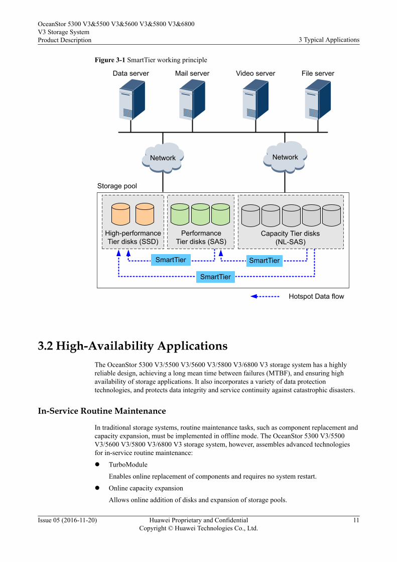
Figure 3-1 SmartTier working principle
Data server Mail server Video server File server
SmartTier
Network Network
Hotspot Data flow
Storage pool
High-performance Tier disks (SSD)
Performance Tier disks (SAS)
Capacity Tier disks (NL-SAS)
SmartTier
SmartTier
3.2 High-Availability ApplicationsThe OceanStor 5300 V3/5500 V3/5600 V3/5800 V3/6800 V3 storage system has a highlyreliable design, achieving a long mean time between failures (MTBF), and ensuring highavailability of storage applications. It also incorporates a variety of data protectiontechnologies, and protects data integrity and service continuity against catastrophic disasters.
In-Service Routine Maintenance
In traditional storage systems, routine maintenance tasks, such as component replacement andcapacity expansion, must be implemented in offline mode. The OceanStor 5300 V3/5500V3/5600 V3/5800 V3/6800 V3 storage system, however, assembles advanced technologiesfor in-service routine maintenance:
l TurboModule
Enables online replacement of components and requires no system restart.
l Online capacity expansion
Allows online addition of disks and expansion of storage pools.
OceanStor 5300 V3&5500 V3&5600 V3&5800 V3&6800V3 Storage SystemProduct Description 3 Typical Applications
Issue 05 (2016-11-20) Huawei Proprietary and ConfidentialCopyright © Huawei Technologies Co., Ltd.
11
Tolerance of Single Points of FailuresThe OceanStor 5300 V3/5500 V3/5600 V3/5800 V3/6800 V3 storage system incorporates ahierarchical redundancy design to eliminate the impact of single points of failure:l Hardware redundancy
All components of the OceanStor 5300 V3/5500 V3/5600 V3/5800 V3/6800 V3 storagesystem are in redundancy and work in active-active mode. If one component fails, theother speeds up to compensate so that the storage system can continue operating.
l Link redundancyIf there is only one link between the storage system and an application server, thedisconnection of the link terminates their communication in between. To eliminate thisfailure, the OceanStor 5300 V3/5500 V3/5600 V3/5800 V3/6800 V3 storage system usestwo or more links to communicate with the application server. Therefore, if one link isdown, the other links take over the services to continue the data transmission.
l Application server clusteringIf the storage system cooperates with only one application server, the failure of theapplication server interrupts services. Application server clustering can address thisissue. A cluster consists of two or more application servers that share loads. If oneapplication server in the cluster fails, the other application servers take over its loads, andthe whole process is transparent to users. Application server clustering supported by theOceanStor 5300 V3/5500 V3/5600 V3/5800 V3/6800 V3 storage system ensuresbusiness continuity.
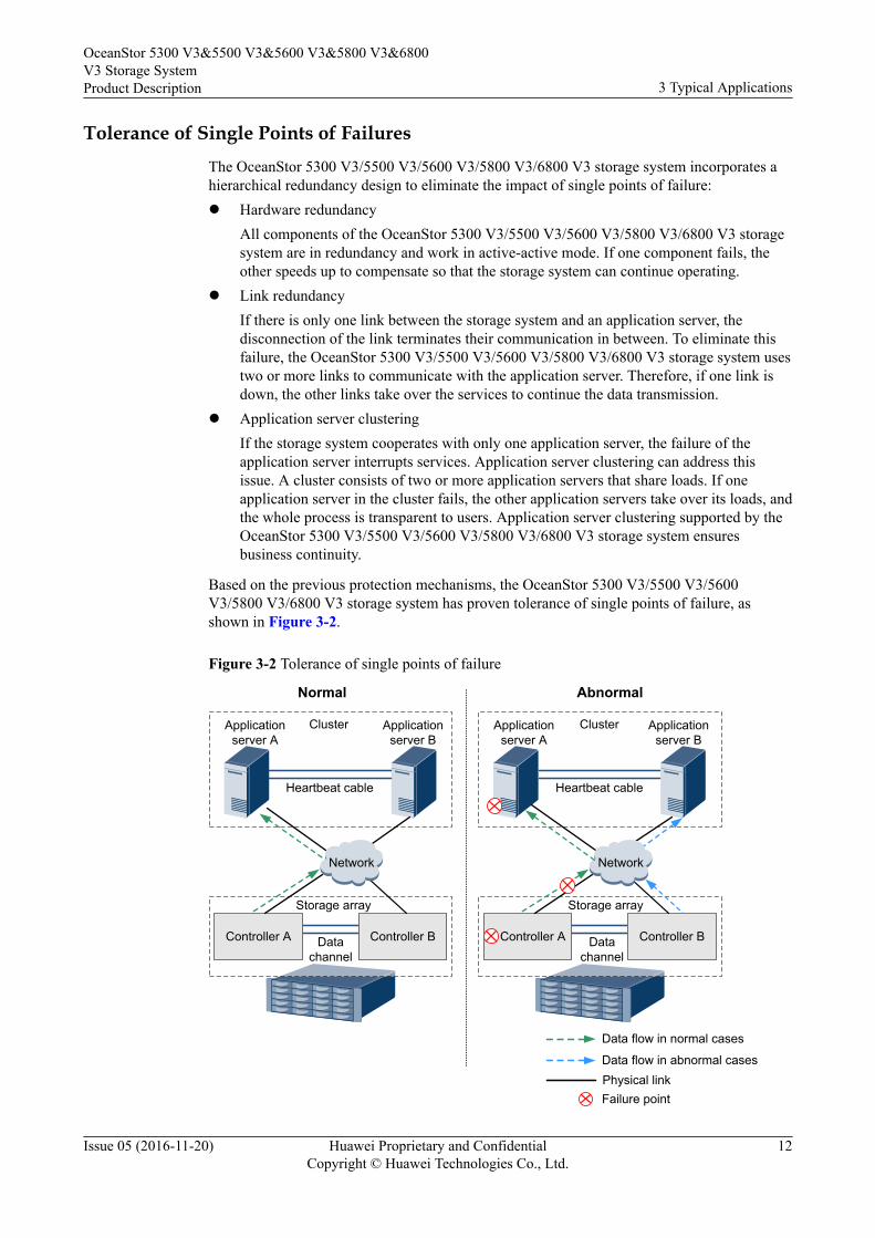
Based on the previous protection mechanisms, the OceanStor 5300 V3/5500 V3/5600V3/5800 V3/6800 V3 storage system has proven tolerance of single points of failure, asshown in Figure 3-2.
Figure 3-2 Tolerance of single points of failure
Application server A
Cluster
Storage array
Controller A Controller B
Heartbeat cable
Normal
Failure point
Abnormal
Data flow in normal cases
Data flow in abnormal cases
Application server B
Application server A
Controller A Controller B
Heartbeat cable
Data channel
Network
Application server B
Network
Data channel
Cluster
Storage array
Physical link
OceanStor 5300 V3&5500 V3&5600 V3&5800 V3&6800V3 Storage SystemProduct Description 3 Typical Applications
Issue 05 (2016-11-20) Huawei Proprietary and ConfidentialCopyright © Huawei Technologies Co., Ltd.
12
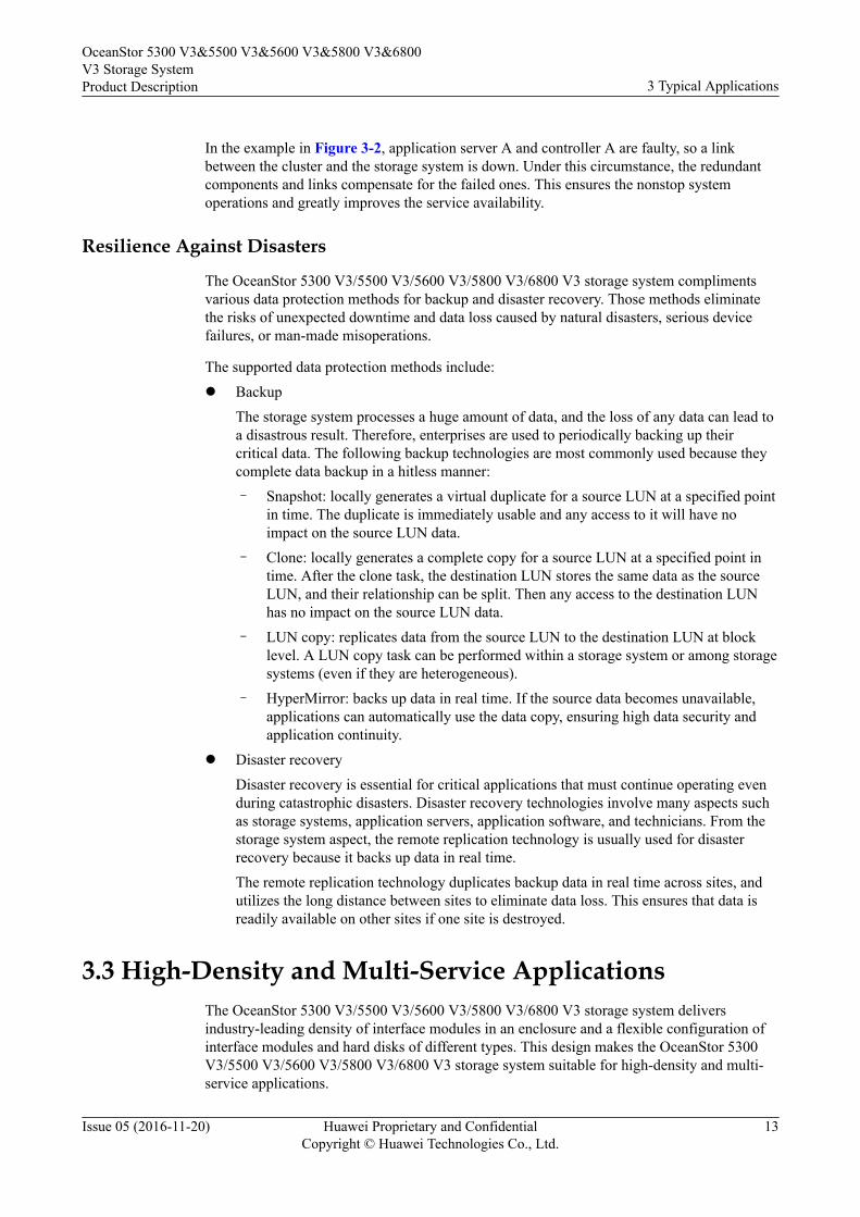
In the example in Figure 3-2, application server A and controller A are faulty, so a linkbetween the cluster and the storage system is down. Under this circumstance, the redundantcomponents and links compensate for the failed ones. This ensures the nonstop systemoperations and greatly improves the service availability.
Resilience Against Disasters
The OceanStor 5300 V3/5500 V3/5600 V3/5800 V3/6800 V3 storage system complimentsvarious data protection methods for backup and disaster recovery. Those methods eliminatethe risks of unexpected downtime and data loss caused by natural disasters, serious devicefailures, or man-made misoperations.
The supported data protection methods include:l Backup
The storage system processes a huge amount of data, and the loss of any data can lead toa disastrous result. Therefore, enterprises are used to periodically backing up theircritical data. The following backup technologies are most commonly used because theycomplete data backup in a hitless manner:– Snapshot: locally generates a virtual duplicate for a source LUN at a specified point
in time. The duplicate is immediately usable and any access to it will have noimpact on the source LUN data.
– Clone: locally generates a complete copy for a source LUN at a specified point intime. After the clone task, the destination LUN stores the same data as the sourceLUN, and their relationship can be split. Then any access to the destination LUNhas no impact on the source LUN data.
– LUN copy: replicates data from the source LUN to the destination LUN at blocklevel. A LUN copy task can be performed within a storage system or among storagesystems (even if they are heterogeneous).
– HyperMirror: backs up data in real time. If the source data becomes unavailable,applications can automatically use the data copy, ensuring high data security andapplication continuity.
l Disaster recoveryDisaster recovery is essential for critical applications that must continue operating evenduring catastrophic disasters. Disaster recovery technologies involve many aspects suchas storage systems, application servers, application software, and technicians. From thestorage system aspect, the remote replication technology is usually used for disasterrecovery because it backs up data in real time.The remote replication technology duplicates backup data in real time across sites, andutilizes the long distance between sites to eliminate data loss. This ensures that data isreadily available on other sites if one site is destroyed.
3.3 High-Density and Multi-Service ApplicationsThe OceanStor 5300 V3/5500 V3/5600 V3/5800 V3/6800 V3 storage system deliversindustry-leading density of interface modules in an enclosure and a flexible configuration ofinterface modules and hard disks of different types. This design makes the OceanStor 5300V3/5500 V3/5600 V3/5800 V3/6800 V3 storage system suitable for high-density and multi-service applications.
OceanStor 5300 V3&5500 V3&5600 V3&5800 V3&6800V3 Storage SystemProduct Description 3 Typical Applications
Issue 05 (2016-11-20) Huawei Proprietary and ConfidentialCopyright © Huawei Technologies Co., Ltd.
13
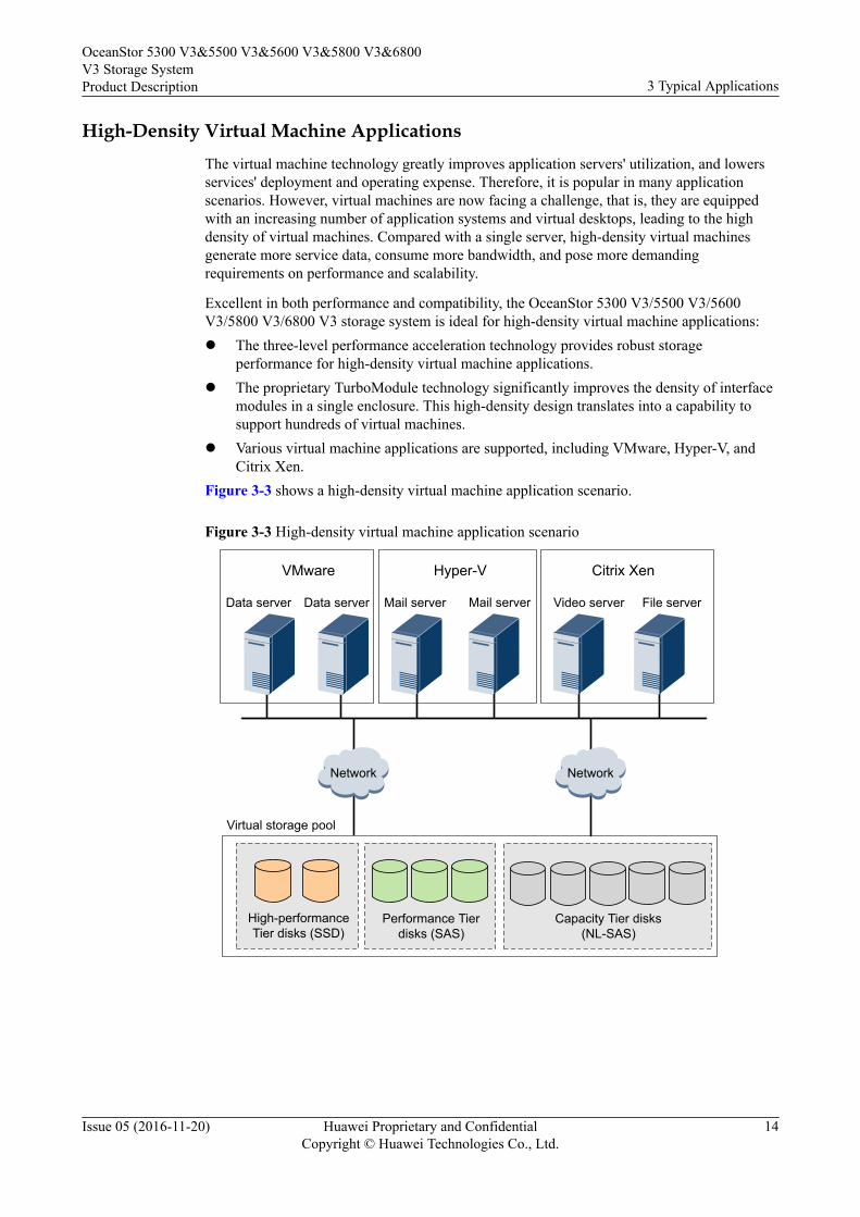
High-Density Virtual Machine ApplicationsThe virtual machine technology greatly improves application servers' utilization, and lowersservices' deployment and operating expense. Therefore, it is popular in many applicationscenarios. However, virtual machines are now facing a challenge, that is, they are equippedwith an increasing number of application systems and virtual desktops, leading to the highdensity of virtual machines. Compared with a single server, high-density virtual machinesgenerate more service data, consume more bandwidth, and pose more demandingrequirements on performance and scalability.
Excellent in both performance and compatibility, the OceanStor 5300 V3/5500 V3/5600V3/5800 V3/6800 V3 storage system is ideal for high-density virtual machine applications:l The three-level performance acceleration technology provides robust storage
performance for high-density virtual machine applications.l The proprietary TurboModule technology significantly improves the density of interface
modules in a single enclosure. This high-density design translates into a capability tosupport hundreds of virtual machines.
l Various virtual machine applications are supported, including VMware, Hyper-V, andCitrix Xen.
Figure 3-3 shows a high-density virtual machine application scenario.
Figure 3-3 High-density virtual machine application scenario
Virtual storage pool
High-performance Tier disks (SSD)
Performance Tier disks (SAS)
Capacity Tier disks (NL-SAS)
Data server Mail server Video server File server
NetworkNetwork
Citrix XenVMware
Data server Mail server
Hyper-V
OceanStor 5300 V3&5500 V3&5600 V3&5800 V3&6800V3 Storage SystemProduct Description 3 Typical Applications
Issue 05 (2016-11-20) Huawei Proprietary and ConfidentialCopyright © Huawei Technologies Co., Ltd.
14
Multi-Service ApplicationsIt is a tendency nowadays for one storage system to process diversified applications.However, those applications have differentiated requirements on storage. Therefore, thestorage system must have high flexibility in performance and networking.
Each type of services has its specific requirements for storage system:l Database servers (featuring unstructured data): high requirements on storage
performance, data integrity, and system stability.l Mail servers (featuring high randomicity of concurrent accesses): high requirements on
storage performance, data integrity, and system stability.l Video servers: high requirements on storage capacity, data access continuity, and
continuous bandwidths.l Backup servers: low requirements on performance and bandwidths.
The OceanStor 5300 V3/5500 V3/5600 V3/5800 V3/6800 V3 storage system supports anintermixed configuration of SSDs, SAS disks, and NL-SAS disks to deliver optimalperformance.l SSDs: deliver the highest performance among these three types of disk, and are suitable
for application servers such as busy database servers and mail servers that requiresuperior storage performance.
l SAS disks: deliver performance lower than SSDs but higher than NL-SAS disks, and aresuitable for application servers such as common database servers, mail servers, and high-definition (HD) video servers that have a moderate storage performance requirement.
l NL-SAS disks: deliver the lowest performance among these three types of disk, and aresuitable for application servers such as low-end video servers and backup servers thathave a low storage performance requirement.
The OceanStor 5300 V3/5500 V3/5600 V3/5800 V3/6800 V3 storage system has a flexibleconfiguration of front-end interface modules with customizable transmission rates,respectively addressing the storage requirements in Fibre Channel networks and Ethernetnetworks, or of Fibre Channel data transmission in Ethernet networks.
Figure 3-4 shows a multi-service application scenario.
OceanStor 5300 V3&5500 V3&5600 V3&5800 V3&6800V3 Storage SystemProduct Description 3 Typical Applications
Issue 05 (2016-11-20) Huawei Proprietary and ConfidentialCopyright © Huawei Technologies Co., Ltd.
15
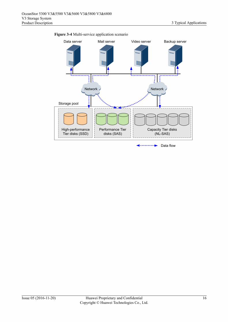
Figure 3-4 Multi-service application scenario
Storage pool
High-performance Tier disks (SSD)
Performance Tier disks (SAS)
Capacity Tier disks (NL-SAS)
Data server Mail server Video server Backup server
NetworkNetwork
Data flow
OceanStor 5300 V3&5500 V3&5600 V3&5800 V3&6800V3 Storage SystemProduct Description 3 Typical Applications
Issue 05 (2016-11-20) Huawei Proprietary and ConfidentialCopyright © Huawei Technologies Co., Ltd.
16
4 Hardware Architecture
About This Chapter
The OceanStor 5300 V3/5500 V3/5600 V3/5800 V3/6800 V3 storage system hardware is thebasis of data storage. A storage unit typically consists of a controller enclosure or a controllerenclosure plus disk enclosures.
4.1 Device CompositionA storage system consists of a controller enclosure and one or more disk enclosures, and itprovides an intelligent storage platform that features robust reliability, high performance, andlarge capacity.
4.2 2 U Controller EnclosureThis chapter describes a controller enclosure in terms of its hardware structure, componentfunctions, front and rear views, and indicators.
4.3 3 U Controller EnclosureThis chapter describes a controller enclosure in terms of its hardware structure, componentfunctions, front and rear views, and indicators.
4.4 6 U Controller EnclosureThis chapter describes a controller enclosure in terms of its hardware structure, componentfunctions, front and rear views, and indicators.
4.5 2 U Disk Enclosure (2.5-Inch Disks)This chapter describes a disk enclosure in terms of its hardware structure, componentfunctions, front and rear views, and indicators.
4.6 4 U Disk Enclosure (3.5-Inch Disks)This chapter describes a disk enclosure in terms of its hardware structure, componentfunctions, front and rear views, and indicators.
4.7 High-Density Disk EnclosureThis chapter describes a high-density disk enclosure in terms of its hardware structure,component functions, front and rear views, and indicators.
4.8 (optional) Data SwitchWhen IP Scale-out is implemented for a storage system and a switch-connection network isused, CE6850-48S4Q-EI data switches are required.
4.9 Device Cables
OceanStor 5300 V3&5500 V3&5600 V3&5800 V3&6800V3 Storage SystemProduct Description 4 Hardware Architecture
Issue 05 (2016-11-20) Huawei Proprietary and ConfidentialCopyright © Huawei Technologies Co., Ltd.
17
Device cables used in the storage system include power cables, ground cables, and signalcables. This chapter displays the views and describes the functions and specifications ofvarious cables.
OceanStor 5300 V3&5500 V3&5600 V3&5800 V3&6800V3 Storage SystemProduct Description 4 Hardware Architecture
Issue 05 (2016-11-20) Huawei Proprietary and ConfidentialCopyright © Huawei Technologies Co., Ltd.
18
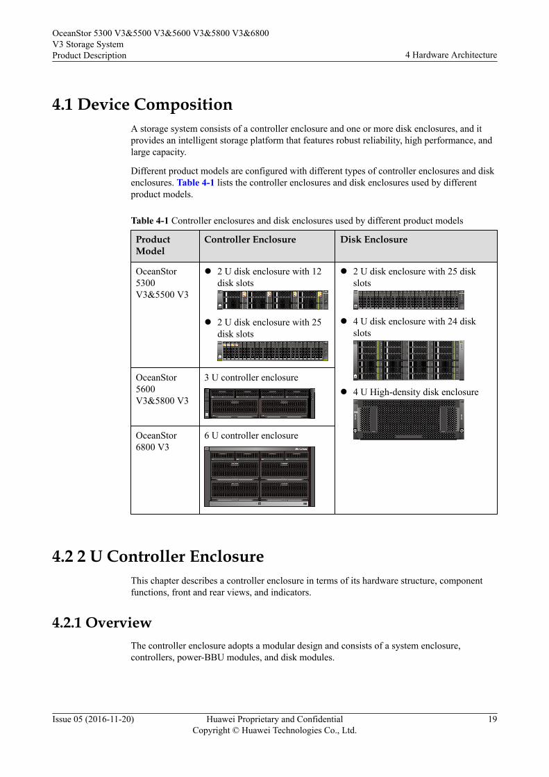
4.1 Device CompositionA storage system consists of a controller enclosure and one or more disk enclosures, and itprovides an intelligent storage platform that features robust reliability, high performance, andlarge capacity.
Different product models are configured with different types of controller enclosures and diskenclosures. Table 4-1 lists the controller enclosures and disk enclosures used by differentproduct models.
Table 4-1 Controller enclosures and disk enclosures used by different product models
ProductModel
Controller Enclosure Disk Enclosure
OceanStor5300V3&5500 V3
l 2 U disk enclosure with 12disk slots
l 2 U disk enclosure with 25disk slots
l 2 U disk enclosure with 25 diskslots
l 4 U disk enclosure with 24 diskslots
l 4 U High-density disk enclosureOceanStor5600V3&5800 V3
3 U controller enclosure
OceanStor6800 V3
6 U controller enclosure
4.2 2 U Controller EnclosureThis chapter describes a controller enclosure in terms of its hardware structure, componentfunctions, front and rear views, and indicators.
4.2.1 OverviewThe controller enclosure adopts a modular design and consists of a system enclosure,controllers, power-BBU modules, and disk modules.
OceanStor 5300 V3&5500 V3&5600 V3&5800 V3&6800V3 Storage SystemProduct Description 4 Hardware Architecture
Issue 05 (2016-11-20) Huawei Proprietary and ConfidentialCopyright © Huawei Technologies Co., Ltd.
19
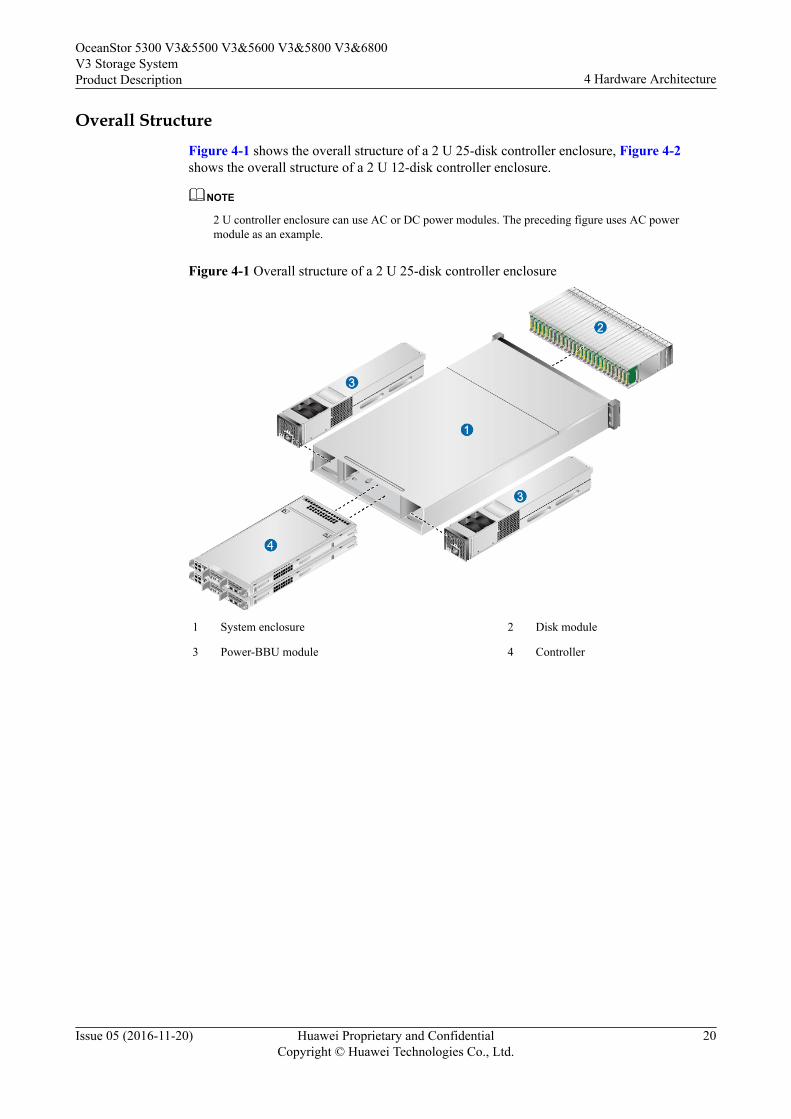
Overall StructureFigure 4-1 shows the overall structure of a 2 U 25-disk controller enclosure, Figure 4-2shows the overall structure of a 2 U 12-disk controller enclosure.
NOTE
2 U controller enclosure can use AC or DC power modules. The preceding figure uses AC powermodule as an example.
Figure 4-1 Overall structure of a 2 U 25-disk controller enclosure
1 System enclosure 2 Disk module
3 Power-BBU module 4 Controller
OceanStor 5300 V3&5500 V3&5600 V3&5800 V3&6800V3 Storage SystemProduct Description 4 Hardware Architecture
Issue 05 (2016-11-20) Huawei Proprietary and ConfidentialCopyright © Huawei Technologies Co., Ltd.
20
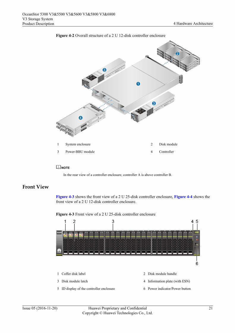
Figure 4-2 Overall structure of a 2 U 12-disk controller enclosure
1 System enclosure 2 Disk module
3 Power-BBU module 4 Controller
NOTE
In the rear view of a controller enclosure, controller A is above controller B.
Front View
Figure 4-3 shows the front view of a 2 U 25-disk controller enclosure, Figure 4-4 shows thefront view of a 2 U 12-disk controller enclosure.
Figure 4-3 Front view of a 2 U 25-disk controller enclosure
1 Coffer disk label 2 Disk module handle
3 Disk module latch 4 Information plate (with ESN)
5 ID display of the controller enclosure 6 Power indicator/Power button
OceanStor 5300 V3&5500 V3&5600 V3&5800 V3&6800V3 Storage SystemProduct Description 4 Hardware Architecture
Issue 05 (2016-11-20) Huawei Proprietary and ConfidentialCopyright © Huawei Technologies Co., Ltd.
21
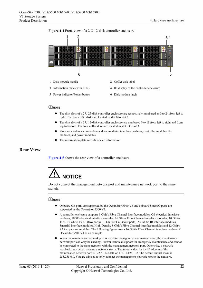
Figure 4-4 Front view of a 2 U 12-disk controller enclosure
1 Disk module handle 2 Coffer disk label
3 Information plate (with ESN) 4 ID display of the controller enclosure
5 Power indicator/Power button 6 Disk module latch
NOTE
l The disk slots of a 2 U 25-disk controller enclosure are respectively numbered as 0 to 24 from left toright. The four coffer disks are located in slot 0 to slot 3.
l The disk slots of a 2 U 12-disk controller enclosure are numbered 0 to 11 from left to right and fromtop to bottom. The four coffer disks are located in slot 0 to slot 3.
l Slots are used to accommodate and secure disks, interface modules, controller modules, fanmodules, and power modules.
l The information plate records device information.
Rear View
Figure 4-5 shows the rear view of a controller enclosure.
NOTICEDo not connect the management network port and maintenance network port to the sameswitch.
NOTE
l Onboard GE ports are supported by the OceanStor 5300 V3 and onboard SmartIO ports aresupported by the OceanStor 5500 V3.
l A controller enclosure supports 8 Gbit/s Fibre Channel interface modules, GE electrical interfacemodules, 10GE electrical interface modules, 16 Gbit/s Fibre Channel interface modules, 10 Gbit/sTOE, 10 Gbit/s FCoE (two ports), 10 Gbit/s FCoE (four ports), 56 Gbit/s IB interface modules,SmartIO interface modules, High-Density 8 Gbit/s Fibre Channel interface modules and 12 Gbit/sSAS expansion modules. The following figure uses a 16 Gbit/s Fibre Channel interface module ofOceanStor 5500 V3 as an example.
l When the maintenance network port is used for management and maintenance, the maintenancenetwork port can only be used by Huawei technical support for emergency maintenance and cannotbe connected to the same network with the management network port. Otherwise, a networkloopback may occur, causing a network storm. The initial value for the IP address of themaintenance network port is 172.31.128.101 or 172.31.128.102. The default subnet mask is255.255.0.0. You are advised to only connect the management network port to the network.
OceanStor 5300 V3&5500 V3&5600 V3&5800 V3&6800V3 Storage SystemProduct Description 4 Hardware Architecture
Issue 05 (2016-11-20) Huawei Proprietary and ConfidentialCopyright © Huawei Technologies Co., Ltd.
22
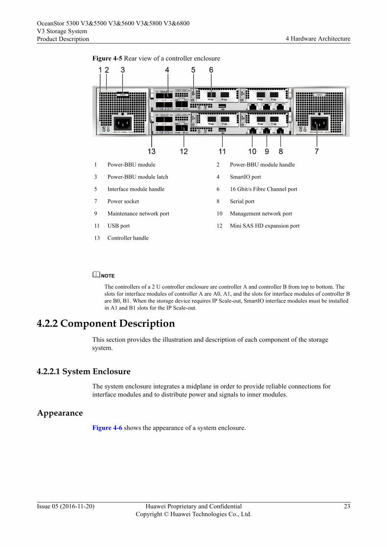
Figure 4-5 Rear view of a controller enclosure
1 Power-BBU module 2 Power-BBU module handle
3 Power-BBU module latch 4 SmartIO port
5 Interface module handle 6 16 Gbit/s Fibre Channel port
7 Power socket 8 Serial port
9 Maintenance network port 10 Management network port
11 USB port 12 Mini SAS HD expansion port
13 Controller handle
NOTE
The controllers of a 2 U controller enclosure are controller A and controller B from top to bottom. Theslots for interface modules of controller A are A0, A1, and the slots for interface modules of controller Bare B0, B1. When the storage device requires IP Scale-out, SmartIO interface modules must be installedin A1 and B1 slots for the IP Scale-out.
4.2.2 Component DescriptionThis section provides the illustration and description of each component of the storagesystem.
4.2.2.1 System EnclosureThe system enclosure integrates a midplane in order to provide reliable connections forinterface modules and to distribute power and signals to inner modules.
AppearanceFigure 4-6 shows the appearance of a system enclosure.
OceanStor 5300 V3&5500 V3&5600 V3&5800 V3&6800V3 Storage SystemProduct Description 4 Hardware Architecture
Issue 05 (2016-11-20) Huawei Proprietary and ConfidentialCopyright © Huawei Technologies Co., Ltd.
23
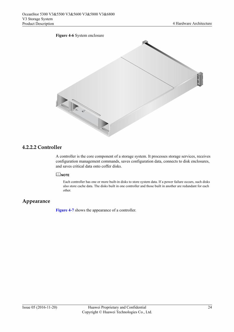
Figure 4-6 System enclosure
4.2.2.2 ControllerA controller is the core component of a storage system. It processes storage services, receivesconfiguration management commands, saves configuration data, connects to disk enclosures,and saves critical data onto coffer disks.
NOTE
Each controller has one or more built-in disks to store system data. If a power failure occurs, such disksalso store cache data. The disks built in one controller and those built in another are redundant for eachother.
AppearanceFigure 4-7 shows the appearance of a controller.
OceanStor 5300 V3&5500 V3&5600 V3&5800 V3&6800V3 Storage SystemProduct Description 4 Hardware Architecture
Issue 05 (2016-11-20) Huawei Proprietary and ConfidentialCopyright © Huawei Technologies Co., Ltd.
24
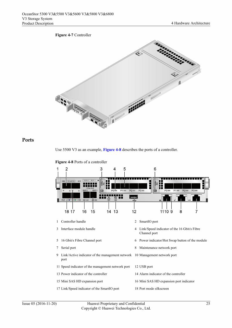
Figure 4-7 Controller
Ports
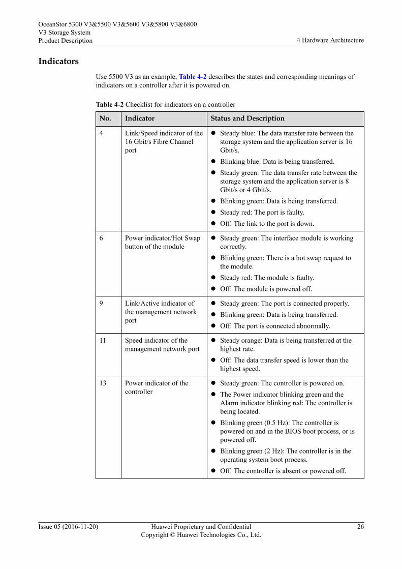
Use 5500 V3 as an example, Figure 4-8 describes the ports of a controller.
Figure 4-8 Ports of a controller
1 Controller handle 2 SmartIO port
3 Interface module handle 4 Link/Speed indicator of the 16 Gbit/s FibreChannel port
5 16 Gbit/s Fibre Channel port 6 Power indicator/Hot Swap button of the module
7 Serial port 8 Maintenance network port
9 Link/Active indicator of the management networkport
10 Management network port
11 Speed indicator of the management network port 12 USB port
13 Power indicator of the controller 14 Alarm indicator of the controller
15 Mini SAS HD expansion port 16 Mini SAS HD expansion port indicator
17 Link/Speed indicator of the SmartIO port 18 Port mode silkscreen
OceanStor 5300 V3&5500 V3&5600 V3&5800 V3&6800V3 Storage SystemProduct Description 4 Hardware Architecture
Issue 05 (2016-11-20) Huawei Proprietary and ConfidentialCopyright © Huawei Technologies Co., Ltd.
25
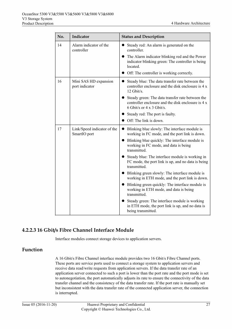
IndicatorsUse 5500 V3 as an example, Table 4-2 describes the states and corresponding meanings ofindicators on a controller after it is powered on.
Table 4-2 Checklist for indicators on a controller
No. Indicator Status and Description
4 Link/Speed indicator of the16 Gbit/s Fibre Channelport
l Steady blue: The data transfer rate between thestorage system and the application server is 16Gbit/s.
l Blinking blue: Data is being transferred.l Steady green: The data transfer rate between the
storage system and the application server is 8Gbit/s or 4 Gbit/s.
l Blinking green: Data is being transferred.l Steady red: The port is faulty.l Off: The link to the port is down.
6 Power indicator/Hot Swapbutton of the module
l Steady green: The interface module is workingcorrectly.
l Blinking green: There is a hot swap request tothe module.
l Steady red: The module is faulty.l Off: The module is powered off.
9 Link/Active indicator ofthe management networkport
l Steady green: The port is connected properly.l Blinking green: Data is being transferred.l Off: The port is connected abnormally.
11 Speed indicator of themanagement network port
l Steady orange: Data is being transferred at thehighest rate.
l Off: The data transfer speed is lower than thehighest speed.
13 Power indicator of thecontroller
l Steady green: The controller is powered on.l The Power indicator blinking green and the
Alarm indicator blinking red: The controller isbeing located.
l Blinking green (0.5 Hz): The controller ispowered on and in the BIOS boot process, or ispowered off.
l Blinking green (2 Hz): The controller is in theoperating system boot process.
l Off: The controller is absent or powered off.
OceanStor 5300 V3&5500 V3&5600 V3&5800 V3&6800V3 Storage SystemProduct Description 4 Hardware Architecture
Issue 05 (2016-11-20) Huawei Proprietary and ConfidentialCopyright © Huawei Technologies Co., Ltd.
26
No. Indicator Status and Description
14 Alarm indicator of thecontroller
l Steady red: An alarm is generated on thecontroller.
l The Alarm indicator blinking red and the Powerindicator blinking green: The controller is beinglocated.
l Off: The controller is working correctly.
16 Mini SAS HD expansionport indicator
l Steady blue: The data transfer rate between thecontroller enclosure and the disk enclosure is 4 x12 Gbit/s.
l Steady green: The data transfer rate between thecontroller enclosure and the disk enclosure is 4 x6 Gbit/s or 4 x 3 Gbit/s.
l Steady red: The port is faulty.l Off: The link is down.
17 Link/Speed indicator of theSmartIO port
l Blinking blue slowly: The interface module isworking in FC mode, and the port link is down.
l Blinking blue quickly: The interface module isworking in FC mode, and data is beingtransmitted.
l Steady blue: The interface module is working inFC mode, the port link is up, and no data is beingtransmitted.
l Blinking green slowly: The interface module isworking in ETH mode, and the port link is down.
l Blinking green quickly: The interface module isworking in ETH mode, and data is beingtransmitted.
l Steady green: The interface module is workingin ETH mode, the port link is up, and no data isbeing transmitted.
4.2.2.3 16 Gbit/s Fibre Channel Interface ModuleInterface modules connect storage devices to application servers.
FunctionA 16 Gbit/s Fibre Channel interface module provides two 16 Gbit/s Fibre Channel ports.These ports are service ports used to connect a storage system to application servers andreceive data read/write requests from application servers. If the data transfer rate of anapplication server connected to such a port is lower than the port rate and the port mode is setto autonegotiation, the port automatically adjusts its rate to ensure the connectivity of the datatransfer channel and the consistency of the data transfer rate. If the port rate is manually setbut inconsistent with the data transfer rate of the connected application server, the connectionis interrupted.
OceanStor 5300 V3&5500 V3&5600 V3&5800 V3&6800V3 Storage SystemProduct Description 4 Hardware Architecture
Issue 05 (2016-11-20) Huawei Proprietary and ConfidentialCopyright © Huawei Technologies Co., Ltd.
27
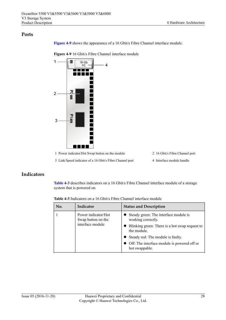
PortsFigure 4-9 shows the appearance of a 16 Gbit/s Fibre Channel interface module.
Figure 4-9 16 Gbit/s Fibre Channel interface module
1 Power indicator/Hot Swap button on the module 2 16 Gbit/s Fibre Channel port
3 Link/Speed indicator of a 16 Gbit/s Fibre Channel port 4 Interface module handle
IndicatorsTable 4-3 describes indicators on a 16 Gbit/s Fibre Channel interface module of a storagesystem that is powered on.
Table 4-3 Indicators on a 16 Gbit/s Fibre Channel interface module
No. Indicator Status and Description
1 Power indicator/HotSwap button on theinterface module
l Steady green: The interface module isworking correctly.
l Blinking green: There is a hot swap request tothe module.
l Steady red: The module is faulty.l Off: The interface module is powered off or
hot swappable.
OceanStor 5300 V3&5500 V3&5600 V3&5800 V3&6800V3 Storage SystemProduct Description 4 Hardware Architecture
Issue 05 (2016-11-20) Huawei Proprietary and ConfidentialCopyright © Huawei Technologies Co., Ltd.
28

No. Indicator Status and Description
3 Link/Speed indicator ofthe 16 Gbit/s FibreChannel port
l Steady blue: The data transfer rate betweenthe storage system and the application serveris 16 Gbit/s.
l Blinking blue: Data is being transferred.l Steady green: The data transfer rate between
the storage system and the application serveris 8 Gbit/s or 4 Gbit/s.
l Blinking green: Data is being transferred.l Steady red: The port is faulty.l Off: The link to the port is down.
4.2.2.4 8 Gbit/s Fibre Channel Interface ModuleInterface modules connect storage devices to application servers.
FunctionAn 8 Gbit/s Fibre Channel interface module provides four 8 Gbit/s Fibre Channel ports. Theseports are service ports used to connect a storage system to application servers and receive dataread/write requests from application servers. If the data transfer rate of an application serverconnected to such a port is lower than the port rate and the port mode is set to autonegotiation,the port automatically adjusts its rate to ensure the connectivity of the data transfer channeland the consistency of the data transfer rate. If the port rate is manually set but inconsistentwith the data transfer rate of the connected application server, the connection is interrupted.
PortsFigure 4-10 shows the appearance of an 8 Gbit/s Fibre Channel interface module.
OceanStor 5300 V3&5500 V3&5600 V3&5800 V3&6800V3 Storage SystemProduct Description 4 Hardware Architecture
Issue 05 (2016-11-20) Huawei Proprietary and ConfidentialCopyright © Huawei Technologies Co., Ltd.
29
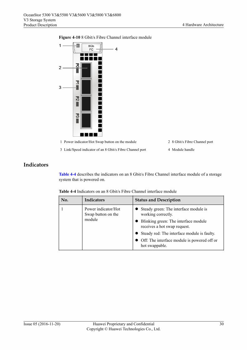
Figure 4-10 8 Gbit/s Fibre Channel interface module
1 Power indicator/Hot Swap button on the module 2 8 Gbit/s Fibre Channel port
3 Link/Speed indicator of an 8 Gbit/s Fibre Channel port 4 Module handle
IndicatorsTable 4-4 describes the indicators on an 8 Gbit/s Fibre Channel interface module of a storagesystem that is powered on.
Table 4-4 Indicators on an 8 Gbit/s Fibre Channel interface module
No. Indicators Status and Description
1 Power indicator/HotSwap button on themodule
l Steady green: The interface module isworking correctly.
l Blinking green: The interface modulereceives a hot swap request.
l Steady red: The interface module is faulty.l Off: The interface module is powered off or
hot swappable.
OceanStor 5300 V3&5500 V3&5600 V3&5800 V3&6800V3 Storage SystemProduct Description 4 Hardware Architecture
Issue 05 (2016-11-20) Huawei Proprietary and ConfidentialCopyright © Huawei Technologies Co., Ltd.
30

No. Indicators Status and Description
3 Link/Speed indicator ofan 8 Gbit/s Fibre Channelport
l Steady blue: The data transfer rate betweenthe storage system and the application serveris 8 Gbit/s.
l Blinking blue: Data is being transferred.l Steady green: The data transfer rate between
the storage system and the application serveris 4 or 2 Gbit/s.
l Blinking green: Data is being transferred.l Steady red: The port is faulty.l Off: The link to the port is down.
4.2.2.5 10 Gbit/s FCoE Interface Module (Two Ports)Interface modules connect storage devices to application servers.
FunctionA 10 Gbit/s FCoE interface module provides two 10 Gbit/s FCoE ports. These ports areservice ports used to connect a storage system to application servers and receive data read/write requests from application servers.
PortsFigure 4-11 shows the appearance of a 10 Gbit/s FCoE interface module.
NOTE
l A 10 Gbit/s two-port FCoE interface module only supports direct connection networking.
l You are not advised to run iSCSI and FCoE protocols simultaneously for a 10 Gbit/s two-portFCoE interface module.
OceanStor 5300 V3&5500 V3&5600 V3&5800 V3&6800V3 Storage SystemProduct Description 4 Hardware Architecture
Issue 05 (2016-11-20) Huawei Proprietary and ConfidentialCopyright © Huawei Technologies Co., Ltd.
31
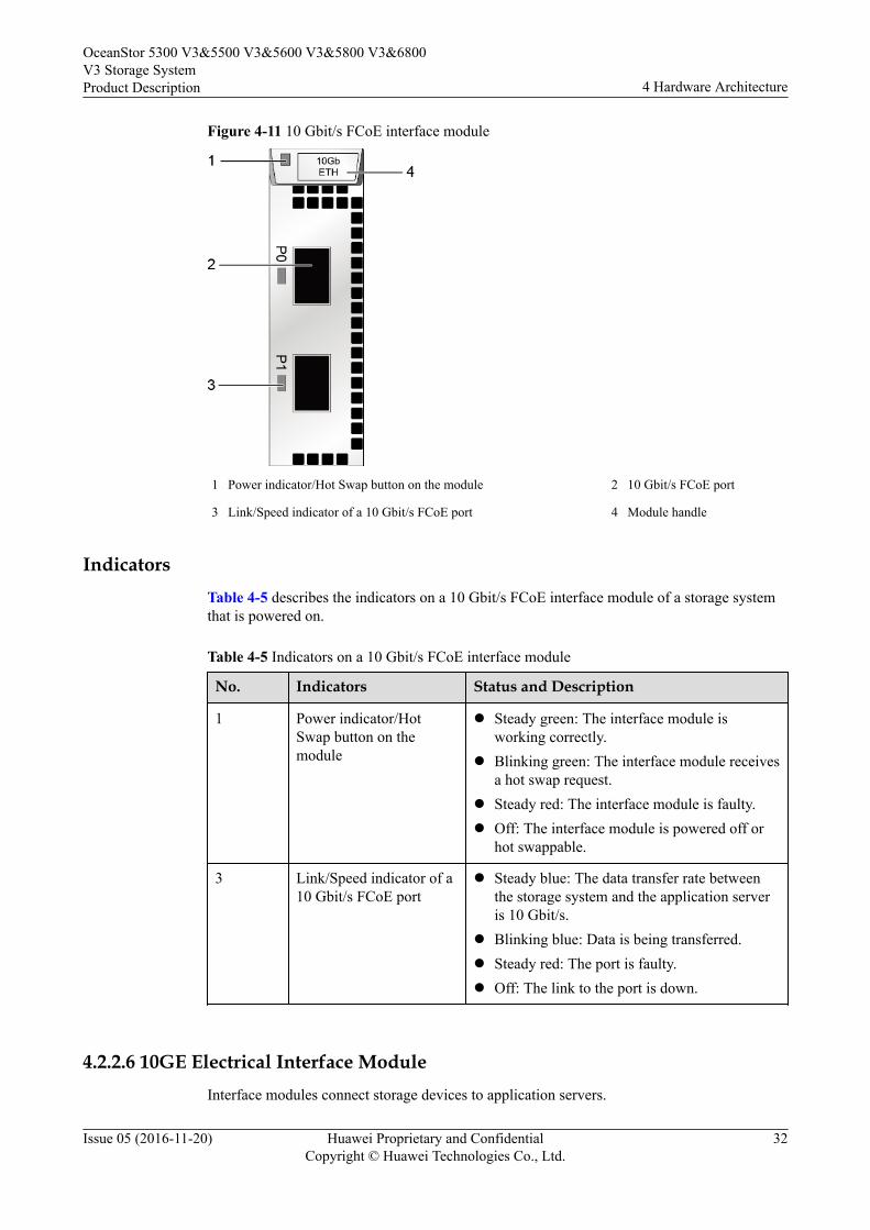
Figure 4-11 10 Gbit/s FCoE interface module
1 Power indicator/Hot Swap button on the module 2 10 Gbit/s FCoE port
3 Link/Speed indicator of a 10 Gbit/s FCoE port 4 Module handle
IndicatorsTable 4-5 describes the indicators on a 10 Gbit/s FCoE interface module of a storage systemthat is powered on.
Table 4-5 Indicators on a 10 Gbit/s FCoE interface module
No. Indicators Status and Description
1 Power indicator/HotSwap button on themodule
l Steady green: The interface module isworking correctly.
l Blinking green: The interface module receivesa hot swap request.
l Steady red: The interface module is faulty.l Off: The interface module is powered off or
hot swappable.
3 Link/Speed indicator of a10 Gbit/s FCoE port
l Steady blue: The data transfer rate betweenthe storage system and the application serveris 10 Gbit/s.
l Blinking blue: Data is being transferred.l Steady red: The port is faulty.l Off: The link to the port is down.
4.2.2.6 10GE Electrical Interface ModuleInterface modules connect storage devices to application servers.
OceanStor 5300 V3&5500 V3&5600 V3&5800 V3&6800V3 Storage SystemProduct Description 4 Hardware Architecture
Issue 05 (2016-11-20) Huawei Proprietary and ConfidentialCopyright © Huawei Technologies Co., Ltd.
32
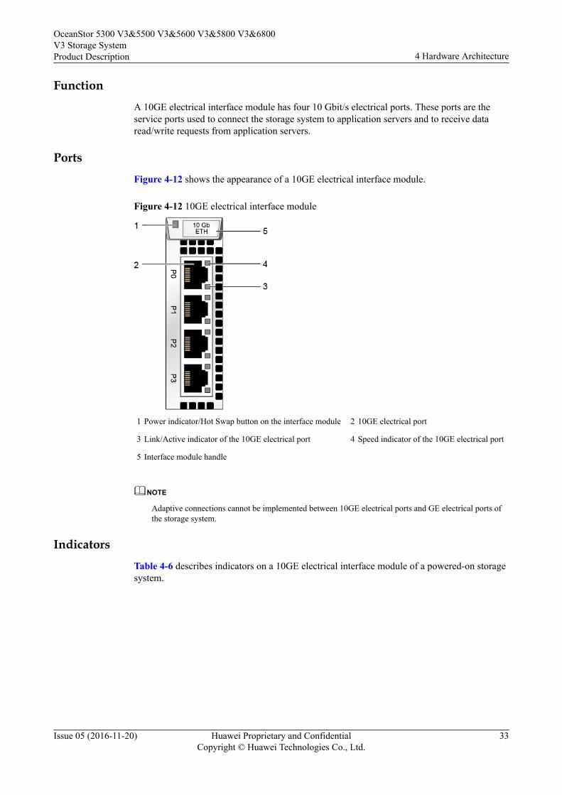
FunctionA 10GE electrical interface module has four 10 Gbit/s electrical ports. These ports are theservice ports used to connect the storage system to application servers and to receive dataread/write requests from application servers.
PortsFigure 4-12 shows the appearance of a 10GE electrical interface module.
Figure 4-12 10GE electrical interface module
1 Power indicator/Hot Swap button on the interface module 2 10GE electrical port
3 Link/Active indicator of the 10GE electrical port 4 Speed indicator of the 10GE electrical port
5 Interface module handle
NOTE
Adaptive connections cannot be implemented between 10GE electrical ports and GE electrical ports ofthe storage system.
IndicatorsTable 4-6 describes indicators on a 10GE electrical interface module of a powered-on storagesystem.
OceanStor 5300 V3&5500 V3&5600 V3&5800 V3&6800V3 Storage SystemProduct Description 4 Hardware Architecture
Issue 05 (2016-11-20) Huawei Proprietary and ConfidentialCopyright © Huawei Technologies Co., Ltd.
33

Table 4-6 Indicators on a 10GE electrical interface module
No. Indicator Status and Description
1 Power indicator/HotSwap button on theinterface module
l Steady green: The interface module isworking correctly.
l Blinking green: There is a hot swap request tothe module.
l Steady red: The module is faulty.l Off: The module is powered off or hot
swappable.
3 Link/Active indicator ofthe 10GE electrical port
l Steady green: The link to the server is normal.l Blinking green: Data is being transferred.l Off: The link to the application server is down
or no link exists.
4 Speed indicator of the10GE electrical port
l Steady orange: The data transfer rate of themanagement network port is 10 Gbit/s.
l Off: The data transfer rate of the managementnetwork port is less than 10 Gbit/s.
4.2.2.7 GE Electrical Interface ModuleInterface modules connect storage devices to application servers.
FunctionA GE electrical interface module has four 1 Gbit/s electrical ports. These ports are the serviceports used to connect the storage system to application servers and to receive data read/writerequests from application servers.
PortsFigure 4-13 shows the appearance of a GE electrical interface module.
OceanStor 5300 V3&5500 V3&5600 V3&5800 V3&6800V3 Storage SystemProduct Description 4 Hardware Architecture
Issue 05 (2016-11-20) Huawei Proprietary and ConfidentialCopyright © Huawei Technologies Co., Ltd.
34
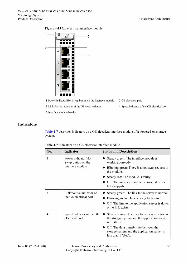
Figure 4-13 GE electrical interface module
1 Power indicator/Hot Swap button on the interface module 2 GE electrical port
3 Link/Active indicator of the GE electrical port 4 Speed indicator of the GE electrical port
5 Interface module handle
Indicators
Table 4-7 describes indicators on a GE electrical interface module of a powered-on storagesystem.
Table 4-7 Indicators on a GE electrical interface module
No. Indicator Status and Description
1 Power indicator/HotSwap button on theinterface module
l Steady green: The interface module isworking correctly.
l Blinking green: There is a hot swap request tothe module.
l Steady red: The module is faulty.l Off: The interface module is powered off or
hot swappable.
3 Link/Active indicator ofthe GE electrical port
l Steady green: The link to the server is normal.l Blinking green: Data is being transferred.l Off: The link to the application server is down
or no link exists.
4 Speed indicator of the GEelectrical port
l Steady orange: The data transfer rate betweenthe storage system and the application serveris 1 Gbit/s.
l Off: The data transfer rate between thestorage system and the application server isless than 1 Gbit/s.
OceanStor 5300 V3&5500 V3&5600 V3&5800 V3&6800V3 Storage SystemProduct Description 4 Hardware Architecture
Issue 05 (2016-11-20) Huawei Proprietary and ConfidentialCopyright © Huawei Technologies Co., Ltd.
35
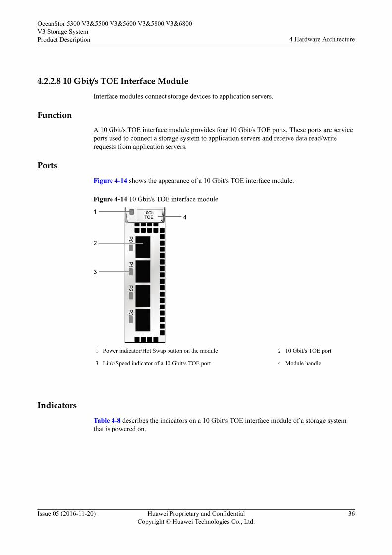
4.2.2.8 10 Gbit/s TOE Interface ModuleInterface modules connect storage devices to application servers.
FunctionA 10 Gbit/s TOE interface module provides four 10 Gbit/s TOE ports. These ports are serviceports used to connect a storage system to application servers and receive data read/writerequests from application servers.
PortsFigure 4-14 shows the appearance of a 10 Gbit/s TOE interface module.
Figure 4-14 10 Gbit/s TOE interface module
1 Power indicator/Hot Swap button on the module 2 10 Gbit/s TOE port
3 Link/Speed indicator of a 10 Gbit/s TOE port 4 Module handle
IndicatorsTable 4-8 describes the indicators on a 10 Gbit/s TOE interface module of a storage systemthat is powered on.
OceanStor 5300 V3&5500 V3&5600 V3&5800 V3&6800V3 Storage SystemProduct Description 4 Hardware Architecture
Issue 05 (2016-11-20) Huawei Proprietary and ConfidentialCopyright © Huawei Technologies Co., Ltd.
36

Table 4-8 Indicators on a 10 Gbit/s TOE interface module
No. Indicators Status and Description
1 Power indicator/HotSwap button on themodule
l Steady green: The interface module isworking correctly.
l Blinking green: The interface modulereceives a hot swap request.
l Steady red: The interface module is faulty.l Off: The interface module is powered off or
hot swappable.
3 Link/Speed indicator of a10 Gbit/s TOE port
l Steady blue: The data transfer rate betweenthe storage system and the application serveris 10 Gbit/s.
l Blinking blue: Data is being transferred.l Steady red: The port is faulty.l Off: The link to the port is down.
4.2.2.9 10 Gbit/s FCoE Interface Module (Four Ports)Interface modules connect storage devices to application servers.
FunctionA 10 Gbit/s FCoE interface module provides four 10 Gbit/s FCoE ports. These ports areservice ports used to connect a storage system to application servers and receive data read/write requests from application servers.
PortsFigure 4-15 shows the appearance of a 10 Gbit/s FCoE interface module.
NOTE
l A 10 Gbit/s four-port FCoE interface module only supports networking through FCoE switches.
l You are not advised to run iSCSI and FCoE protocols simultaneously for a 10 Gbit/s four-port FCoEinterface module.
OceanStor 5300 V3&5500 V3&5600 V3&5800 V3&6800V3 Storage SystemProduct Description 4 Hardware Architecture
Issue 05 (2016-11-20) Huawei Proprietary and ConfidentialCopyright © Huawei Technologies Co., Ltd.
37
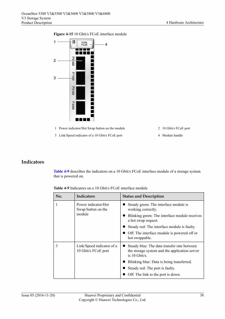
Figure 4-15 10 Gbit/s FCoE interface module
1 Power indicator/Hot Swap button on the module 2 10 Gbit/s FCoE port
3 Link/Speed indicator of a 10 Gbit/s FCoE port 4 Module handle
Indicators
Table 4-9 describes the indicators on a 10 Gbit/s FCoE interface module of a storage systemthat is powered on.
Table 4-9 Indicators on a 10 Gbit/s FCoE interface module
No. Indicators Status and Description
1 Power indicator/HotSwap button on themodule
l Steady green: The interface module isworking correctly.
l Blinking green: The interface module receivesa hot swap request.
l Steady red: The interface module is faulty.l Off: The interface module is powered off or
hot swappable.
3 Link/Speed indicator of a10 Gbit/s FCoE port
l Steady blue: The data transfer rate betweenthe storage system and the application serveris 10 Gbit/s.
l Blinking blue: Data is being transferred.l Steady red: The port is faulty.l Off: The link to the port is down.
OceanStor 5300 V3&5500 V3&5600 V3&5800 V3&6800V3 Storage SystemProduct Description 4 Hardware Architecture
Issue 05 (2016-11-20) Huawei Proprietary and ConfidentialCopyright © Huawei Technologies Co., Ltd.
38

4.2.2.10 56 Gbit/s IB Interface ModuleInterface modules connect storage devices to application servers.
FunctionA 56 Gbit/s IB interface module provides two 4 x 14 Gbit/s IB ports. Both are the serviceports used to connect to application servers and to receive data read/write requests fromapplication servers.
InterfaceFigure 4-16 shows the appearance of a 56 Gbit/s IB interface module.
Figure 4-16 56 Gbit/s IB interface module
1 Power indicator/Hot Swap button of the module 2 56 Gbit/s IB port Link indicator
3 56 Gbit/s IB port Active indicator 4 56 Gbit/s IB port
5 Module handle
IndicatorsTable 4-10 describes the states of indicators and their meanings on a 56 Gbit/s IB interfacemodule after the storage device is powered on.
OceanStor 5300 V3&5500 V3&5600 V3&5800 V3&6800V3 Storage SystemProduct Description 4 Hardware Architecture
Issue 05 (2016-11-20) Huawei Proprietary and ConfidentialCopyright © Huawei Technologies Co., Ltd.
39

Table 4-10 Indicator status description for a 56 Gbit/s IB interface module
No. Indicator Status Description
1 Power indicator/HotSwap button of themodule
l Steady green: The interface module isworking correctly.
l Blinking green: There is a hot swap request tothe module.
l Steady red: The module is faulty.l Off: The interface module is powered off or
hot swappable.
2 56 Gbit/s IB port Linkindicator
l Steady green: The port is connected properly.l Off: The port link is down.
3 56 Gbit/s IB port Activeindicator
l Steady orange: Data is being transmitted.l Off: No data is being transmitted.
4.2.2.11 SmartIO Interface ModuleInterface modules are mainly used to connect storage devices to application servers.
FunctionA SmartIO interface module provides 16 Gbit/s, 8 Gbit/s and 10 Gbit/s optical transceiver.They are the service ports used to connect to application servers and to receive data read/writerequests from application servers.
InterfaceFigure 4-17 shows the components of a SmartIO interface module.
OceanStor 5300 V3&5500 V3&5600 V3&5800 V3&6800V3 Storage SystemProduct Description 4 Hardware Architecture
Issue 05 (2016-11-20) Huawei Proprietary and ConfidentialCopyright © Huawei Technologies Co., Ltd.
40

Figure 4-17 SmartIO interface module
1 Module Power/Hot Swap indicator 2 SmartIO port
3 Port Link/Active/Mode indicator 4 Port mode silkscreen
5 Module handle
IndicatorsTable 4-11 describes the states of indicators and their meanings on a SmartIO interfacemodule after the storage device is powered on.
Table 4-11 Indicator status description for a SmartIO interface module
No. Indicator Status Description
1 Module Power/Hot Swapbutton
l Steady green: The interface module isrunning properly.
l Blinking green: The interface modulereceives a hot swap request.
l Steady red: The interface module is faulty.l Off: The interface module is not powered on
or can be hot-swapped.
OceanStor 5300 V3&5500 V3&5600 V3&5800 V3&6800V3 Storage SystemProduct Description 4 Hardware Architecture
Issue 05 (2016-11-20) Huawei Proprietary and ConfidentialCopyright © Huawei Technologies Co., Ltd.
41

No. Indicator Status Description
3 Port Link/Active/Modeindicator
l Blinking blue slowly: The interface module isworking in FC mode, and the port link isdown.
l Blinking blue quickly: The interface moduleis working in FC mode, and data is beingtransmitted.
l Steady blue: The interface module is workingin FC mode, the port link is up, and no data isbeing transmitted.
l Blinking green slowly: The interface moduleis working in ETH mode, and the port link isdown.
l Blinking green quickly: The interface moduleis working in ETH mode, and data is beingtransmitted.
l Steady green: The interface module isworking in ETH mode, the port link is up, andno data is being transmitted.
l Steady red: The port is faulty.l Blinking red: The port is being located.l Off: The port is not powered on.
NOTE
l If the mode of the SmartIO port is set to FCoE/iSCSI or Cluster on the software interface, the portindicator is in ETH mode. The SmartIO port need to configure with 10 Gbit/s optical modules.
l If the mode of the SmartIO port is set to FC on the software interface, the port indicator is in FCmode. The SmartIO port need to configure with 8 Gbit/s or 16 Gbit/s optical modules.
l Connect a network only through FCoE switches when the SmartIO interface module is set to FCoE/iSCSI and the host uses the FCoE protocol. The SmartIO port need to configure with 10 Gbit/soptical modules.
4.2.2.12 Smart ACC Module (Applicable to V300R003C00/V300R003C10)
Smart ACC modules are mainly used to improve system performance.
Function
Smart ACC modules can concurrently provide functions such as fixed-length deduplication,fingerprint computing, and hardware acceleration for GZIP compression and decompression,reducing CPU load and promoting deduplication and compression performance.
Interface
Figure 4-18 shows the components of a Smart ACC module.
OceanStor 5300 V3&5500 V3&5600 V3&5800 V3&6800V3 Storage SystemProduct Description 4 Hardware Architecture
Issue 05 (2016-11-20) Huawei Proprietary and ConfidentialCopyright © Huawei Technologies Co., Ltd.
42
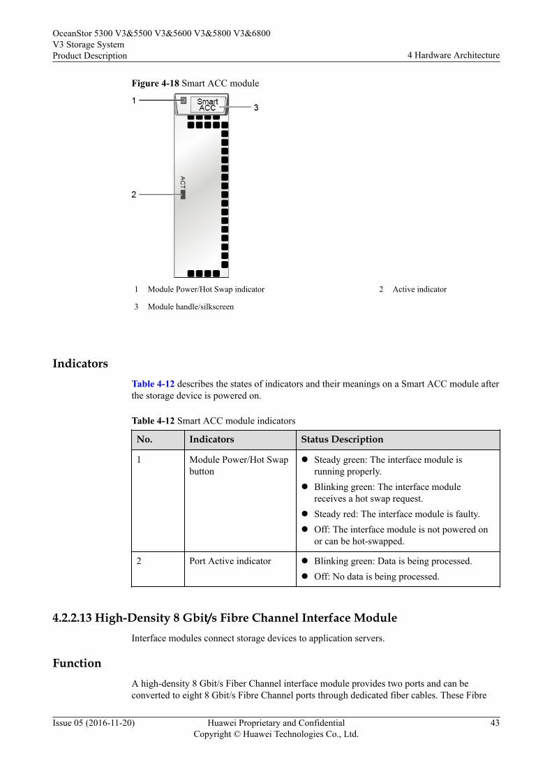
Figure 4-18 Smart ACC module
1 Module Power/Hot Swap indicator 2 Active indicator
3 Module handle/silkscreen
IndicatorsTable 4-12 describes the states of indicators and their meanings on a Smart ACC module afterthe storage device is powered on.
Table 4-12 Smart ACC module indicators
No. Indicators Status Description
1 Module Power/Hot Swapbutton
l Steady green: The interface module isrunning properly.
l Blinking green: The interface modulereceives a hot swap request.
l Steady red: The interface module is faulty.l Off: The interface module is not powered on
or can be hot-swapped.
2 Port Active indicator l Blinking green: Data is being processed.l Off: No data is being processed.
4.2.2.13 High-Density 8 Gbit/s Fibre Channel Interface ModuleInterface modules connect storage devices to application servers.
FunctionA high-density 8 Gbit/s Fiber Channel interface module provides two ports and can beconverted to eight 8 Gbit/s Fibre Channel ports through dedicated fiber cables. These Fibre
OceanStor 5300 V3&5500 V3&5600 V3&5800 V3&6800V3 Storage SystemProduct Description 4 Hardware Architecture
Issue 05 (2016-11-20) Huawei Proprietary and ConfidentialCopyright © Huawei Technologies Co., Ltd.
43

Channel ports can be used for a storage system to receive data exchange commands fromapplication servers. If the data transfer rate of an application server is lower than the FibreChannel port rate which is set to autonegotiation, the Fibre Channel port adapts itself to thedata transfer rate of the application server. Autonegotiation ensures the connectivity of thedata transfer channel and consistency of data transfer rates. If the port rate is manually set anddiffers from the application server's transfer rate, the storage system will be disconnectedfrom the application server.
Interface
Figure 4-19 shows the appearance of a high-density 8 Gbit/s Fibre Channel interface module.
Figure 4-19 High-density 8 Gbit/s Fibre Channel interface module
1 Module Power/Hot Swap indicator 2 8 Gbit/s Fibre Channel ports
3 Port Link/Speed indicator 4 Module handle
Indicators
Table 4-13 describes the states of indicators and their meanings on a high-density 8 Gbit/sFibre Channel interface module after the storage device is powered on.
Table 4-13 Indicator status description for a high-density 8 Gbit/s Fibre Channel interfacemodule
No. Indicator Status Description
1 Module Power/Hot Swapindicator
l Steady green: The interface module isrunning properly.
l Blinking green: The interface modulereceives a hot swap request.
l Steady red: The interface module is faulty.l Off: The interface module is not powered on
or can be hot-swapped.
OceanStor 5300 V3&5500 V3&5600 V3&5800 V3&6800V3 Storage SystemProduct Description 4 Hardware Architecture
Issue 05 (2016-11-20) Huawei Proprietary and ConfidentialCopyright © Huawei Technologies Co., Ltd.
44
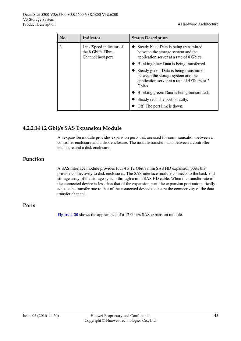
No. Indicator Status Description
3 Link/Speed indicator ofthe 8 Gbit/s FibreChannel host port
l Steady blue: Data is being transmittedbetween the storage system and theapplication server at a rate of 8 Gbit/s.
l Blinking blue: Data is being transferred.l Steady green: Data is being transmitted
between the storage system and theapplication server at a rate of 4 Gbit/s or 2Gbit/s.
l Blinking green: Data is being transmitted.l Steady red: The port is faulty.l Off: The port link is down.
4.2.2.14 12 Gbit/s SAS Expansion ModuleAn expansion module provides expansion ports that are used for communication between acontroller enclosure and a disk enclosure. The module transfers data between a controllerenclosure and a disk enclosure.
FunctionA SAS interface module provides four 4 x 12 Gbit/s mini SAS HD expansion ports thatprovide connectivity to disk enclosures. The SAS interface module connects to the back-endstorage array of the storage system through a mini SAS HD cable. When the transfer rate ofthe connected device is less than that of the expansion port, the expansion port automaticallyadjusts the transfer rate to that of the connected device to ensure the connectivity of the datatransfer channel.
PortsFigure 4-20 shows the appearance of a 12 Gbit/s SAS expansion module.
OceanStor 5300 V3&5500 V3&5600 V3&5800 V3&6800V3 Storage SystemProduct Description 4 Hardware Architecture
Issue 05 (2016-11-20) Huawei Proprietary and ConfidentialCopyright © Huawei Technologies Co., Ltd.
45
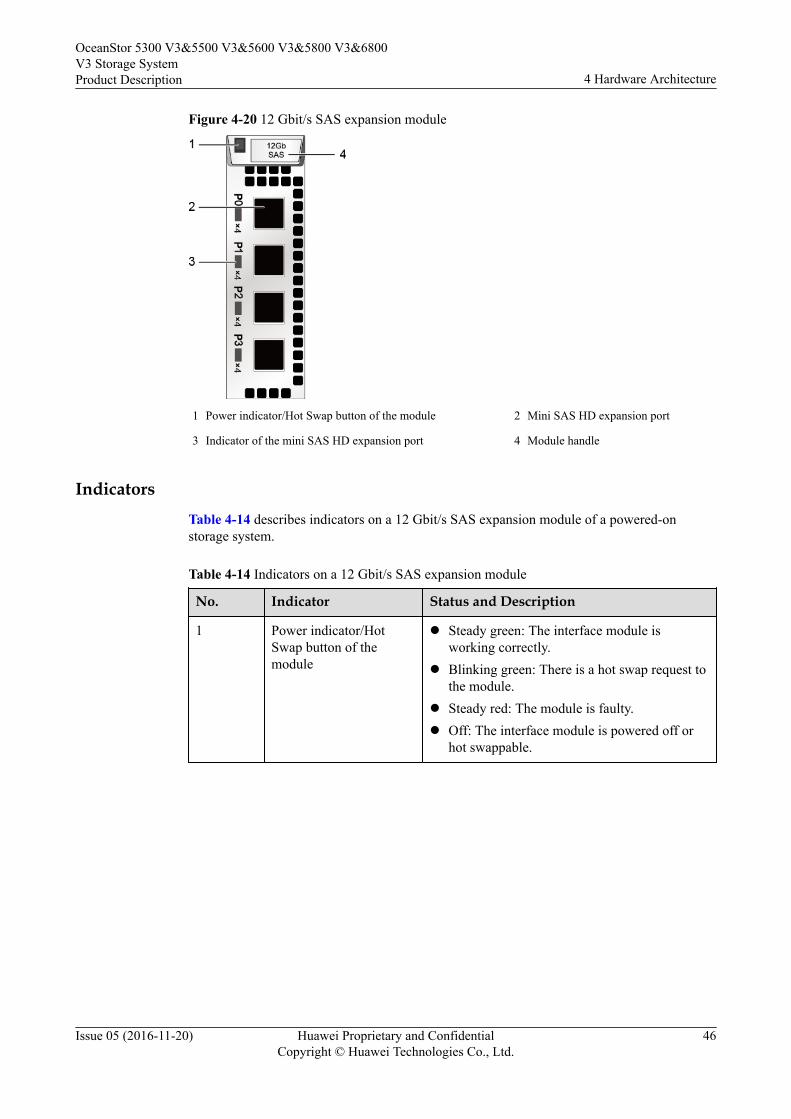
Figure 4-20 12 Gbit/s SAS expansion module
1 Power indicator/Hot Swap button of the module 2 Mini SAS HD expansion port
3 Indicator of the mini SAS HD expansion port 4 Module handle
IndicatorsTable 4-14 describes indicators on a 12 Gbit/s SAS expansion module of a powered-onstorage system.
Table 4-14 Indicators on a 12 Gbit/s SAS expansion module
No. Indicator Status and Description
1 Power indicator/HotSwap button of themodule
l Steady green: The interface module isworking correctly.
l Blinking green: There is a hot swap request tothe module.
l Steady red: The module is faulty.l Off: The interface module is powered off or
hot swappable.
OceanStor 5300 V3&5500 V3&5600 V3&5800 V3&6800V3 Storage SystemProduct Description 4 Hardware Architecture
Issue 05 (2016-11-20) Huawei Proprietary and ConfidentialCopyright © Huawei Technologies Co., Ltd.
46
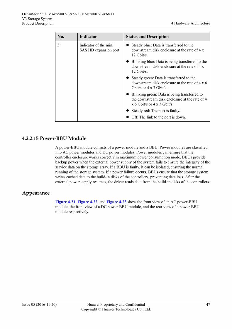
No. Indicator Status and Description
3 Indicator of the miniSAS HD expansion port
l Steady blue: Data is transferred to thedownstream disk enclosure at the rate of 4 x12 Gbit/s.
l Blinking blue: Data is being transferred to thedownstream disk enclosure at the rate of 4 x12 Gbit/s.
l Steady green: Data is transferred to thedownstream disk enclosure at the rate of 4 x 6Gbit/s or 4 x 3 Gbit/s.
l Blinking green: Data is being transferred tothe downstream disk enclosure at the rate of 4x 6 Gbit/s or 4 x 3 Gbit/s.
l Steady red: The port is faulty.l Off: The link to the port is down.
4.2.2.15 Power-BBU ModuleA power-BBU module consists of a power module and a BBU. Power modules are classifiedinto AC power modules and DC power modules. Power modules can ensure that thecontroller enclosure works correctly in maximum power consumption mode. BBUs providebackup power when the external power supply of the system fails to ensure the integrity of theservice data on the storage array. If a BBU is faulty, it can be isolated, ensuring the normalrunning of the storage system. If a power failure occurs, BBUs ensure that the storage systemwrites cached data to the build-in disks of the controllers, preventing data loss. After theexternal power supply resumes, the driver reads data from the build-in disks of the controllers.
AppearanceFigure 4-21, Figure 4-22, and Figure 4-23 show the front view of an AC power-BBUmodule, the front view of a DC power-BBU module, and the rear view of a power-BBUmodule respectively.
OceanStor 5300 V3&5500 V3&5600 V3&5800 V3&6800V3 Storage SystemProduct Description 4 Hardware Architecture
Issue 05 (2016-11-20) Huawei Proprietary and ConfidentialCopyright © Huawei Technologies Co., Ltd.
47
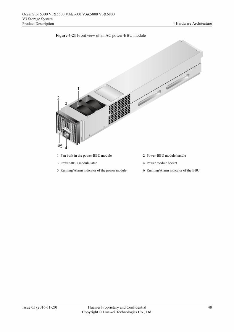
Figure 4-21 Front view of an AC power-BBU module
1 Fan built in the power-BBU module 2 Power-BBU module handle
3 Power-BBU module latch 4 Power module socket
5 Running/Alarm indicator of the power module 6 Running/Alarm indicator of the BBU
OceanStor 5300 V3&5500 V3&5600 V3&5800 V3&6800V3 Storage SystemProduct Description 4 Hardware Architecture
Issue 05 (2016-11-20) Huawei Proprietary and ConfidentialCopyright © Huawei Technologies Co., Ltd.
48
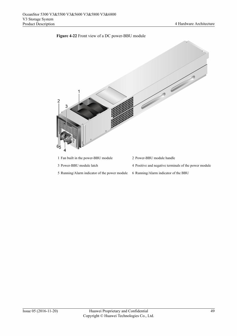
Figure 4-22 Front view of a DC power-BBU module
1 Fan built in the power-BBU module 2 Power-BBU module handle
3 Power-BBU module latch 4 Positive and negative terminals of the power module
5 Running/Alarm indicator of the power module 6 Running/Alarm indicator of the BBU
OceanStor 5300 V3&5500 V3&5600 V3&5800 V3&6800V3 Storage SystemProduct Description 4 Hardware Architecture
Issue 05 (2016-11-20) Huawei Proprietary and ConfidentialCopyright © Huawei Technologies Co., Ltd.
49
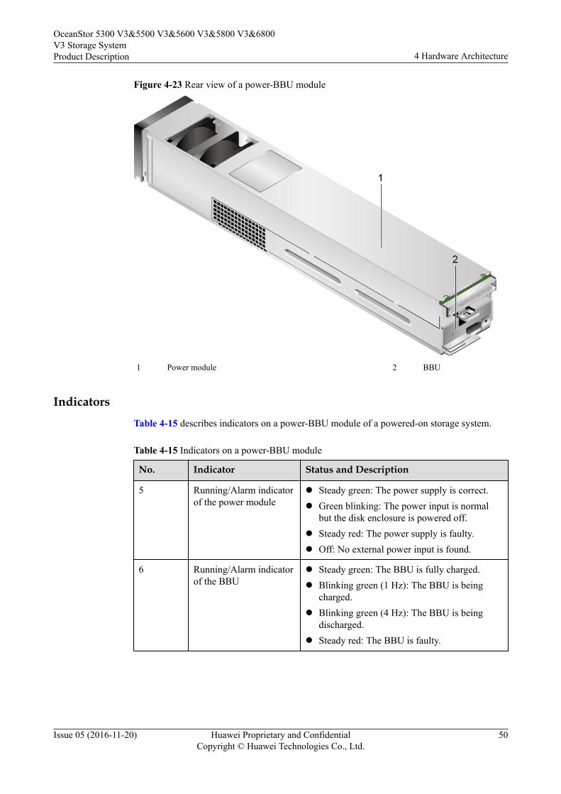
Figure 4-23 Rear view of a power-BBU module
1 Power module 2 BBU
IndicatorsTable 4-15 describes indicators on a power-BBU module of a powered-on storage system.
Table 4-15 Indicators on a power-BBU module
No. Indicator Status and Description
5 Running/Alarm indicatorof the power module
l Steady green: The power supply is correct.l Green blinking: The power input is normal
but the disk enclosure is powered off.l Steady red: The power supply is faulty.l Off: No external power input is found.
6 Running/Alarm indicatorof the BBU
l Steady green: The BBU is fully charged.l Blinking green (1 Hz): The BBU is being
charged.l Blinking green (4 Hz): The BBU is being
discharged.l Steady red: The BBU is faulty.
OceanStor 5300 V3&5500 V3&5600 V3&5800 V3&6800V3 Storage SystemProduct Description 4 Hardware Architecture
Issue 05 (2016-11-20) Huawei Proprietary and ConfidentialCopyright © Huawei Technologies Co., Ltd.
50
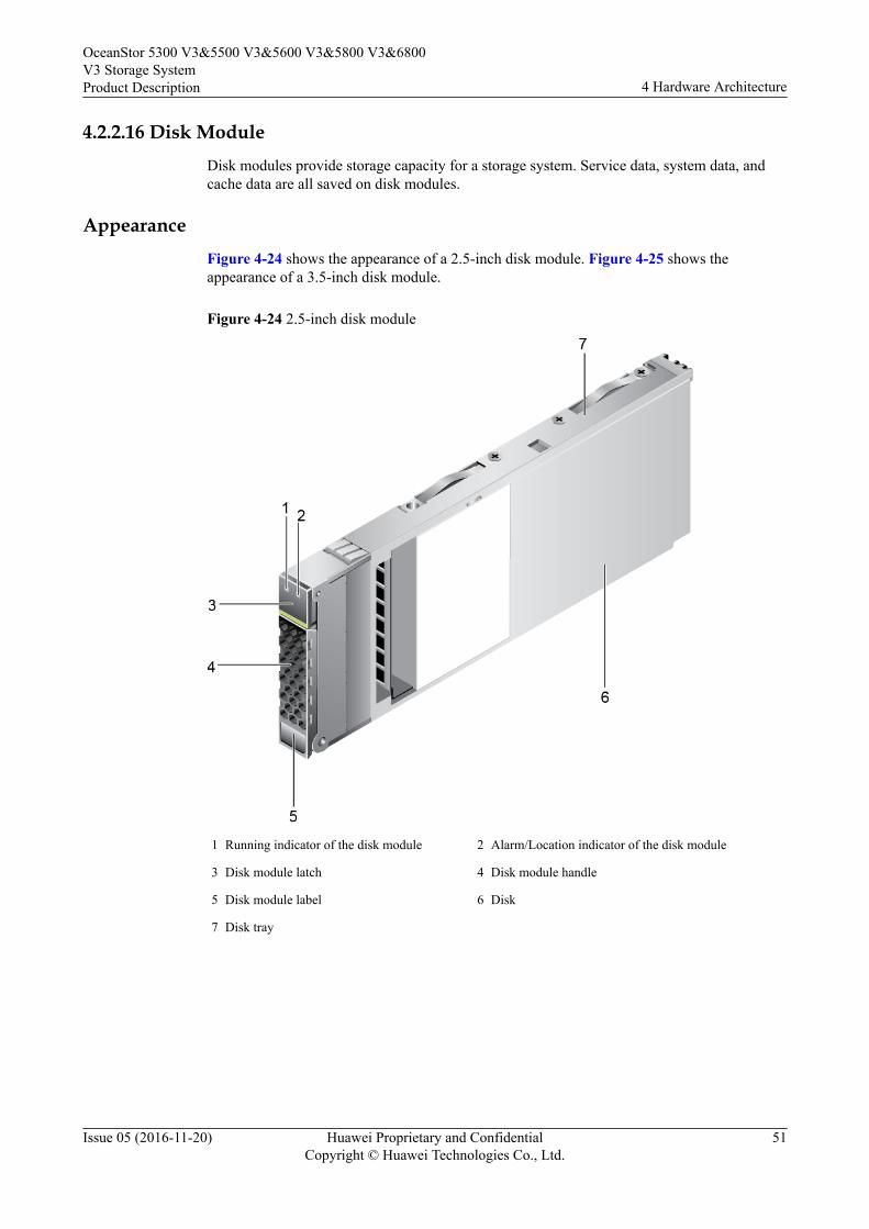
4.2.2.16 Disk ModuleDisk modules provide storage capacity for a storage system. Service data, system data, andcache data are all saved on disk modules.
AppearanceFigure 4-24 shows the appearance of a 2.5-inch disk module. Figure 4-25 shows theappearance of a 3.5-inch disk module.
Figure 4-24 2.5-inch disk module
1 Running indicator of the disk module 2 Alarm/Location indicator of the disk module
3 Disk module latch 4 Disk module handle
5 Disk module label 6 Disk
7 Disk tray
OceanStor 5300 V3&5500 V3&5600 V3&5800 V3&6800V3 Storage SystemProduct Description 4 Hardware Architecture
Issue 05 (2016-11-20) Huawei Proprietary and ConfidentialCopyright © Huawei Technologies Co., Ltd.
51
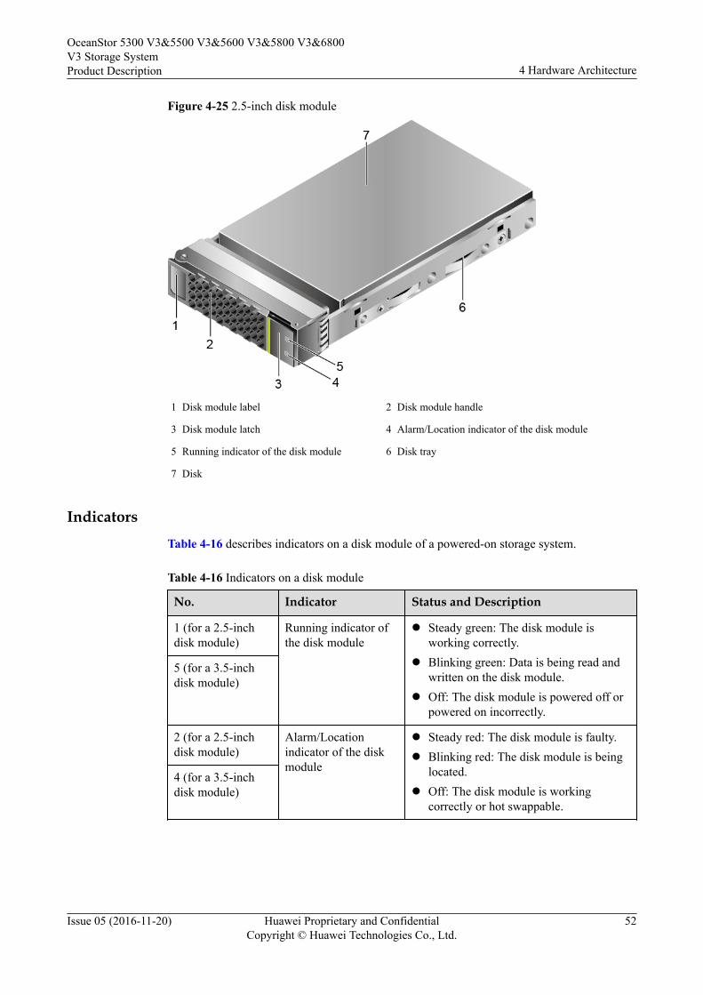
Figure 4-25 2.5-inch disk module
1 Disk module label 2 Disk module handle
3 Disk module latch 4 Alarm/Location indicator of the disk module
5 Running indicator of the disk module 6 Disk tray
7 Disk
IndicatorsTable 4-16 describes indicators on a disk module of a powered-on storage system.
Table 4-16 Indicators on a disk module
No. Indicator Status and Description
1 (for a 2.5-inchdisk module)
Running indicator ofthe disk module
l Steady green: The disk module isworking correctly.
l Blinking green: Data is being read andwritten on the disk module.
l Off: The disk module is powered off orpowered on incorrectly.
5 (for a 3.5-inchdisk module)
2 (for a 2.5-inchdisk module)
Alarm/Locationindicator of the diskmodule
l Steady red: The disk module is faulty.l Blinking red: The disk module is being
located.l Off: The disk module is working
correctly or hot swappable.
4 (for a 3.5-inchdisk module)
OceanStor 5300 V3&5500 V3&5600 V3&5800 V3&6800V3 Storage SystemProduct Description 4 Hardware Architecture
Issue 05 (2016-11-20) Huawei Proprietary and ConfidentialCopyright © Huawei Technologies Co., Ltd.
52
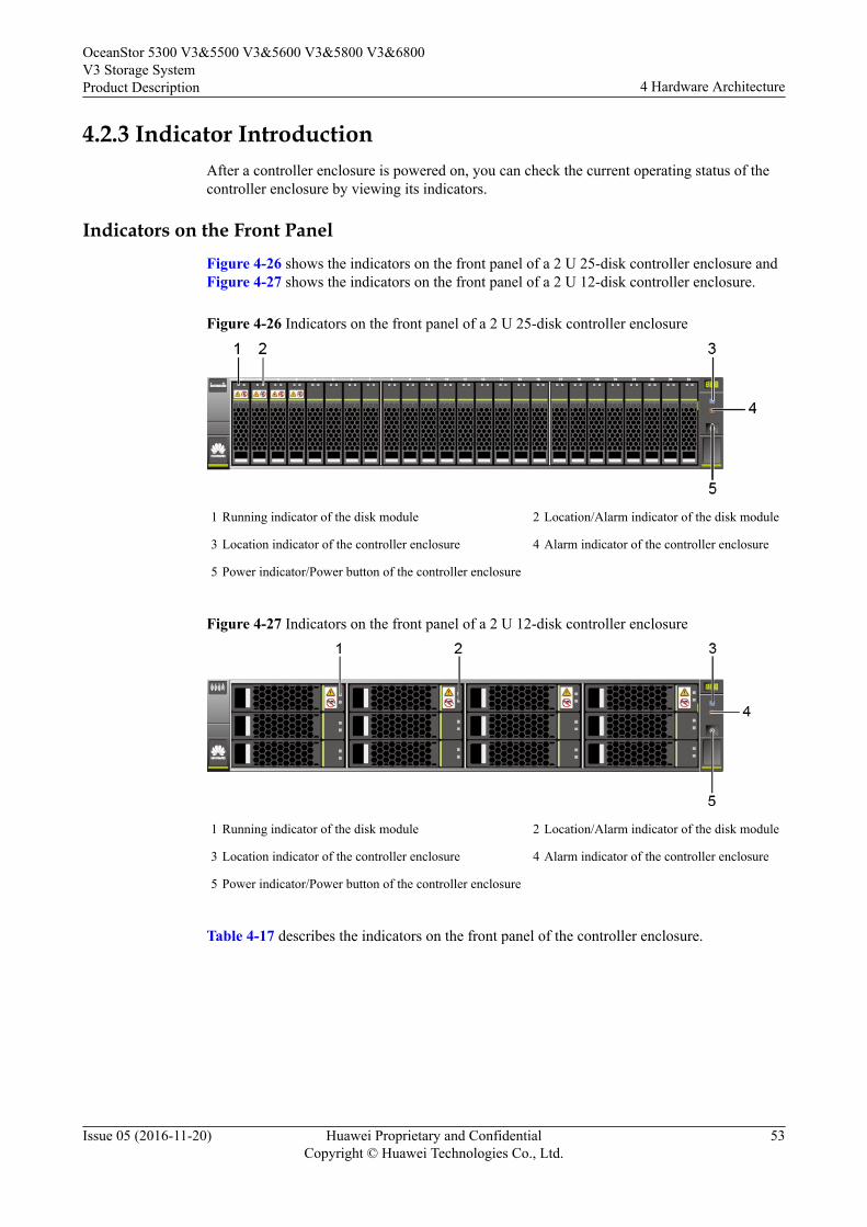
4.2.3 Indicator IntroductionAfter a controller enclosure is powered on, you can check the current operating status of thecontroller enclosure by viewing its indicators.
Indicators on the Front PanelFigure 4-26 shows the indicators on the front panel of a 2 U 25-disk controller enclosure andFigure 4-27 shows the indicators on the front panel of a 2 U 12-disk controller enclosure.
Figure 4-26 Indicators on the front panel of a 2 U 25-disk controller enclosure
1 Running indicator of the disk module 2 Location/Alarm indicator of the disk module
3 Location indicator of the controller enclosure 4 Alarm indicator of the controller enclosure
5 Power indicator/Power button of the controller enclosure
Figure 4-27 Indicators on the front panel of a 2 U 12-disk controller enclosure
1 Running indicator of the disk module 2 Location/Alarm indicator of the disk module
3 Location indicator of the controller enclosure 4 Alarm indicator of the controller enclosure
5 Power indicator/Power button of the controller enclosure
Table 4-17 describes the indicators on the front panel of the controller enclosure.
OceanStor 5300 V3&5500 V3&5600 V3&5800 V3&6800V3 Storage SystemProduct Description 4 Hardware Architecture
Issue 05 (2016-11-20) Huawei Proprietary and ConfidentialCopyright © Huawei Technologies Co., Ltd.
53
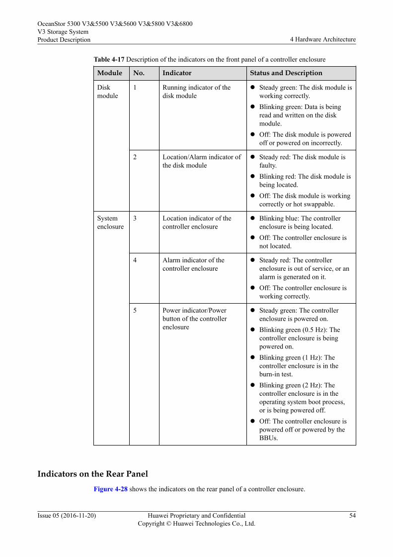
Table 4-17 Description of the indicators on the front panel of a controller enclosure
Module No. Indicator Status and Description
Diskmodule
1 Running indicator of thedisk module
l Steady green: The disk module isworking correctly.
l Blinking green: Data is beingread and written on the diskmodule.
l Off: The disk module is poweredoff or powered on incorrectly.
2 Location/Alarm indicator ofthe disk module
l Steady red: The disk module isfaulty.
l Blinking red: The disk module isbeing located.
l Off: The disk module is workingcorrectly or hot swappable.
Systemenclosure
3 Location indicator of thecontroller enclosure
l Blinking blue: The controllerenclosure is being located.
l Off: The controller enclosure isnot located.
4 Alarm indicator of thecontroller enclosure
l Steady red: The controllerenclosure is out of service, or analarm is generated on it.
l Off: The controller enclosure isworking correctly.
5 Power indicator/Powerbutton of the controllerenclosure
l Steady green: The controllerenclosure is powered on.
l Blinking green (0.5 Hz): Thecontroller enclosure is beingpowered on.
l Blinking green (1 Hz): Thecontroller enclosure is in theburn-in test.
l Blinking green (2 Hz): Thecontroller enclosure is in theoperating system boot process,or is being powered off.
l Off: The controller enclosure ispowered off or powered by theBBUs.
Indicators on the Rear PanelFigure 4-28 shows the indicators on the rear panel of a controller enclosure.
OceanStor 5300 V3&5500 V3&5600 V3&5800 V3&6800V3 Storage SystemProduct Description 4 Hardware Architecture
Issue 05 (2016-11-20) Huawei Proprietary and ConfidentialCopyright © Huawei Technologies Co., Ltd.
54
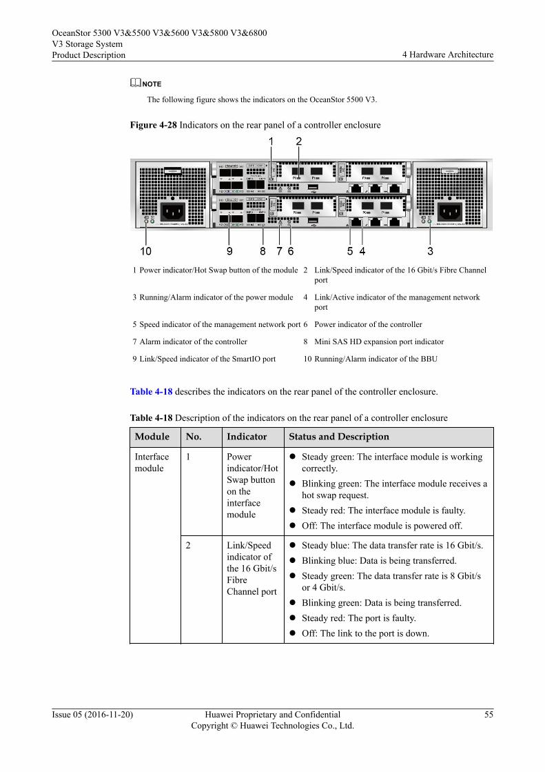
NOTE
The following figure shows the indicators on the OceanStor 5500 V3.
Figure 4-28 Indicators on the rear panel of a controller enclosure
1 Power indicator/Hot Swap button of the module 2 Link/Speed indicator of the 16 Gbit/s Fibre Channelport
3 Running/Alarm indicator of the power module 4 Link/Active indicator of the management networkport
5 Speed indicator of the management network port 6 Power indicator of the controller
7 Alarm indicator of the controller 8 Mini SAS HD expansion port indicator
9 Link/Speed indicator of the SmartIO port 10 Running/Alarm indicator of the BBU
Table 4-18 describes the indicators on the rear panel of the controller enclosure.
Table 4-18 Description of the indicators on the rear panel of a controller enclosure
Module No. Indicator Status and Description
Interfacemodule
1 Powerindicator/HotSwap buttonon theinterfacemodule
l Steady green: The interface module is workingcorrectly.
l Blinking green: The interface module receives ahot swap request.
l Steady red: The interface module is faulty.l Off: The interface module is powered off.
2 Link/Speedindicator ofthe 16 Gbit/sFibreChannel port
l Steady blue: The data transfer rate is 16 Gbit/s.l Blinking blue: Data is being transferred.l Steady green: The data transfer rate is 8 Gbit/s
or 4 Gbit/s.l Blinking green: Data is being transferred.l Steady red: The port is faulty.l Off: The link to the port is down.
OceanStor 5300 V3&5500 V3&5600 V3&5800 V3&6800V3 Storage SystemProduct Description 4 Hardware Architecture
Issue 05 (2016-11-20) Huawei Proprietary and ConfidentialCopyright © Huawei Technologies Co., Ltd.
55
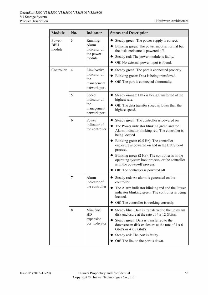
Module No. Indicator Status and Description
Power-BBUmodule
3 Running/Alarmindicator ofthe powermodule
l Steady green: The power supply is correct.l Blinking green: The power input is normal but
the disk enclosure is powered off.l Steady red: The power module is faulty.l Off: No external power input is found.
Controller 4 Link/Activeindicator ofthemanagementnetwork port
l Steady green: The port is connected properly.l Blinking green: Data is being transferred.l Off: The port is connected abnormally.
5 Speedindicator ofthemanagementnetwork port
l Steady orange: Data is being transferred at thehighest rate.
l Off: The data transfer speed is lower than thehighest speed.
6 Powerindicator ofthe controller
l Steady green: The controller is powered on.l The Power indicator blinking green and the
Alarm indicator blinking red: The controller isbeing located.
l Blinking green (0.5 Hz): The controllerenclosure is powered on and in the BIOS bootprocess.
l Blinking green (2 Hz): The controller is in theoperating system boot process, or the controlleris in the power-off process.
l Off: The controller is powered off.
7 Alarmindicator ofthe controller
l Steady red: An alarm is generated on thecontroller.
l The Alarm indicator blinking red and the Powerindicator blinking green: The controller is beinglocated.
l Off: The controller is working correctly.
8 Mini SASHDexpansionport indicator
l Steady blue: Data is transferred to the upstreamdisk enclosure at the rate of 4 x 12 Gbit/s.
l Steady green: Data is transferred to thedownstream disk enclosure at the rate of 4 x 6Gbit/s or 4 x 3 Gbit/s.
l Steady red: The port is faulty.l Off: The link to the port is down.
OceanStor 5300 V3&5500 V3&5600 V3&5800 V3&6800V3 Storage SystemProduct Description 4 Hardware Architecture
Issue 05 (2016-11-20) Huawei Proprietary and ConfidentialCopyright © Huawei Technologies Co., Ltd.
56
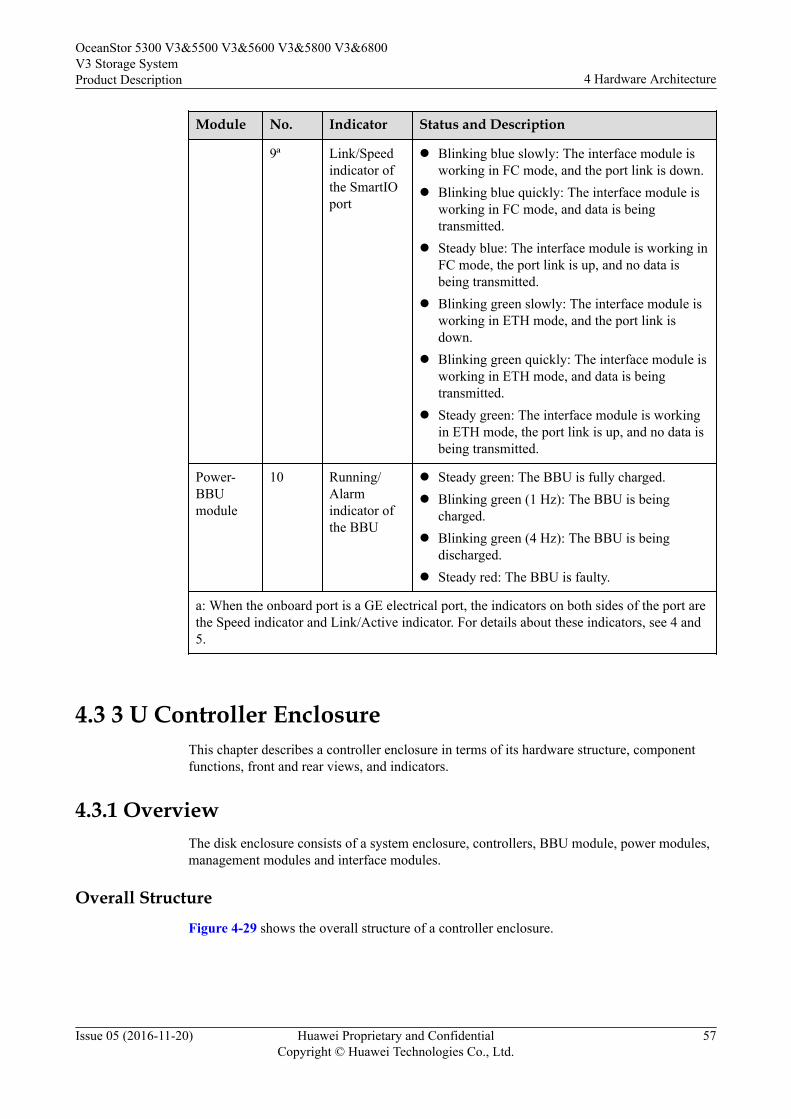
Module No. Indicator Status and Description
9ª Link/Speedindicator ofthe SmartIOport
l Blinking blue slowly: The interface module isworking in FC mode, and the port link is down.
l Blinking blue quickly: The interface module isworking in FC mode, and data is beingtransmitted.
l Steady blue: The interface module is working inFC mode, the port link is up, and no data isbeing transmitted.
l Blinking green slowly: The interface module isworking in ETH mode, and the port link isdown.
l Blinking green quickly: The interface module isworking in ETH mode, and data is beingtransmitted.
l Steady green: The interface module is workingin ETH mode, the port link is up, and no data isbeing transmitted.
Power-BBUmodule
10 Running/Alarmindicator ofthe BBU
l Steady green: The BBU is fully charged.l Blinking green (1 Hz): The BBU is being
charged.l Blinking green (4 Hz): The BBU is being
discharged.l Steady red: The BBU is faulty.
a: When the onboard port is a GE electrical port, the indicators on both sides of the port arethe Speed indicator and Link/Active indicator. For details about these indicators, see 4 and5.
4.3 3 U Controller EnclosureThis chapter describes a controller enclosure in terms of its hardware structure, componentfunctions, front and rear views, and indicators.
4.3.1 OverviewThe disk enclosure consists of a system enclosure, controllers, BBU module, power modules,management modules and interface modules.
Overall StructureFigure 4-29 shows the overall structure of a controller enclosure.
OceanStor 5300 V3&5500 V3&5600 V3&5800 V3&6800V3 Storage SystemProduct Description 4 Hardware Architecture
Issue 05 (2016-11-20) Huawei Proprietary and ConfidentialCopyright © Huawei Technologies Co., Ltd.
57
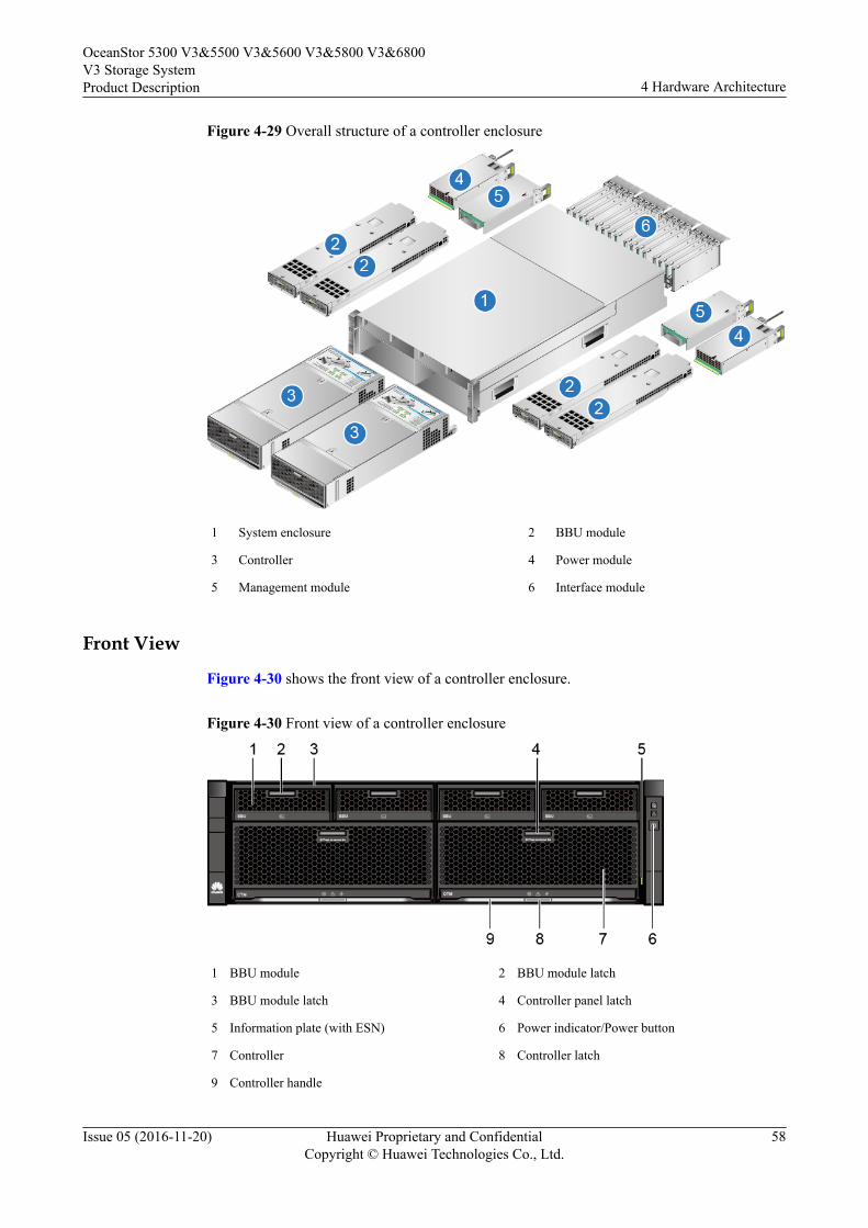
Figure 4-29 Overall structure of a controller enclosure
1 System enclosure 2 BBU module
3 Controller 4 Power module
5 Management module 6 Interface module
Front View
Figure 4-30 shows the front view of a controller enclosure.
Figure 4-30 Front view of a controller enclosure
1 BBU module 2 BBU module latch
3 BBU module latch 4 Controller panel latch
5 Information plate (with ESN) 6 Power indicator/Power button
7 Controller 8 Controller latch
9 Controller handle
OceanStor 5300 V3&5500 V3&5600 V3&5800 V3&6800V3 Storage SystemProduct Description 4 Hardware Architecture
Issue 05 (2016-11-20) Huawei Proprietary and ConfidentialCopyright © Huawei Technologies Co., Ltd.
58
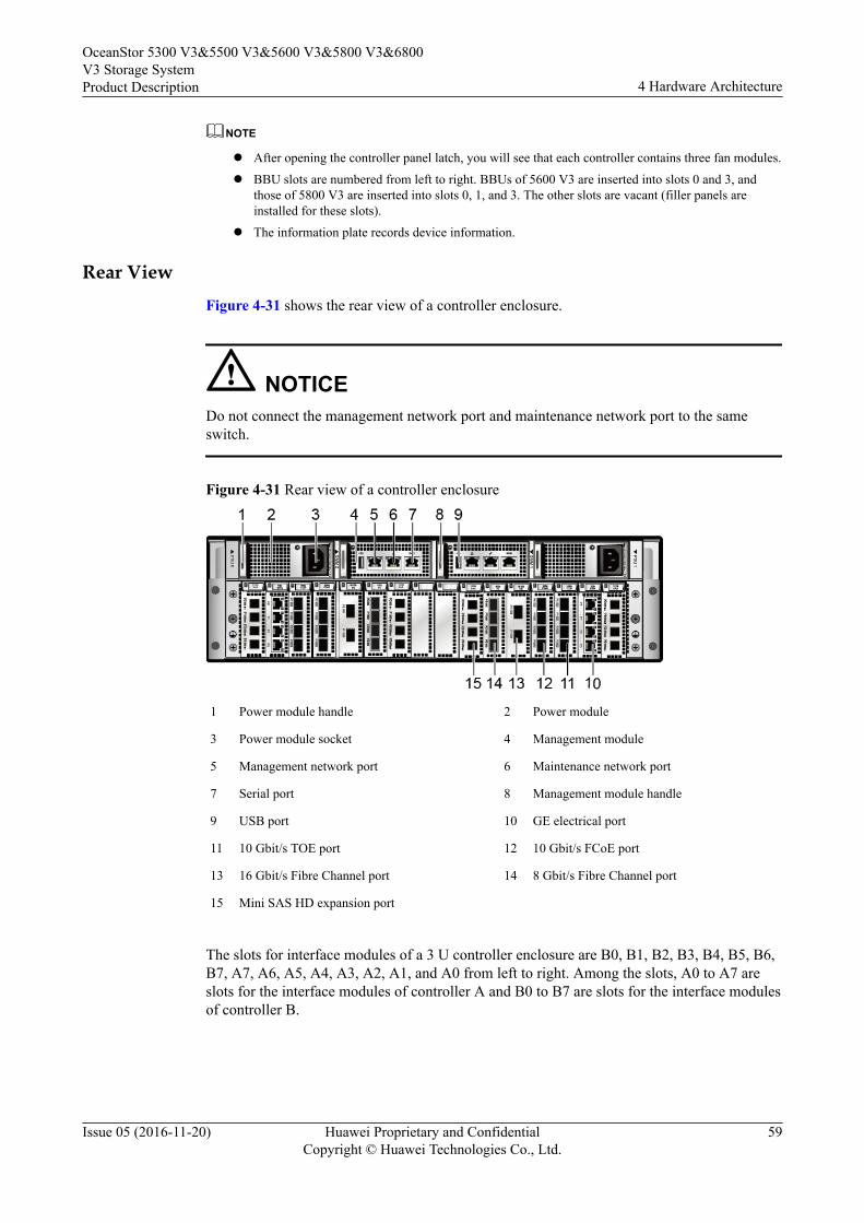
NOTE
l After opening the controller panel latch, you will see that each controller contains three fan modules.
l BBU slots are numbered from left to right. BBUs of 5600 V3 are inserted into slots 0 and 3, andthose of 5800 V3 are inserted into slots 0, 1, and 3. The other slots are vacant (filler panels areinstalled for these slots).
l The information plate records device information.
Rear ViewFigure 4-31 shows the rear view of a controller enclosure.
NOTICEDo not connect the management network port and maintenance network port to the sameswitch.
Figure 4-31 Rear view of a controller enclosure
1 Power module handle 2 Power module
3 Power module socket 4 Management module
5 Management network port 6 Maintenance network port
7 Serial port 8 Management module handle
9 USB port 10 GE electrical port
11 10 Gbit/s TOE port 12 10 Gbit/s FCoE port
13 16 Gbit/s Fibre Channel port 14 8 Gbit/s Fibre Channel port
15 Mini SAS HD expansion port
The slots for interface modules of a 3 U controller enclosure are B0, B1, B2, B3, B4, B5, B6,B7, A7, A6, A5, A4, A3, A2, A1, and A0 from left to right. Among the slots, A0 to A7 areslots for the interface modules of controller A and B0 to B7 are slots for the interface modulesof controller B.
OceanStor 5300 V3&5500 V3&5600 V3&5800 V3&6800V3 Storage SystemProduct Description 4 Hardware Architecture
Issue 05 (2016-11-20) Huawei Proprietary and ConfidentialCopyright © Huawei Technologies Co., Ltd.
59
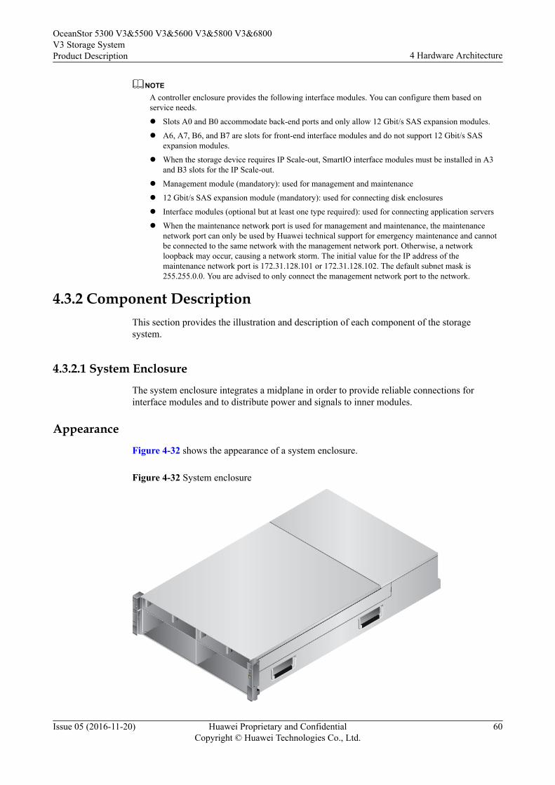
NOTEA controller enclosure provides the following interface modules. You can configure them based onservice needs.
l Slots A0 and B0 accommodate back-end ports and only allow 12 Gbit/s SAS expansion modules.
l A6, A7, B6, and B7 are slots for front-end interface modules and do not support 12 Gbit/s SASexpansion modules.
l When the storage device requires IP Scale-out, SmartIO interface modules must be installed in A3and B3 slots for the IP Scale-out.
l Management module (mandatory): used for management and maintenance
l 12 Gbit/s SAS expansion module (mandatory): used for connecting disk enclosures
l Interface modules (optional but at least one type required): used for connecting application servers
l When the maintenance network port is used for management and maintenance, the maintenancenetwork port can only be used by Huawei technical support for emergency maintenance and cannotbe connected to the same network with the management network port. Otherwise, a networkloopback may occur, causing a network storm. The initial value for the IP address of themaintenance network port is 172.31.128.101 or 172.31.128.102. The default subnet mask is255.255.0.0. You are advised to only connect the management network port to the network.
4.3.2 Component DescriptionThis section provides the illustration and description of each component of the storagesystem.
4.3.2.1 System Enclosure
The system enclosure integrates a midplane in order to provide reliable connections forinterface modules and to distribute power and signals to inner modules.
Appearance
Figure 4-32 shows the appearance of a system enclosure.
Figure 4-32 System enclosure
OceanStor 5300 V3&5500 V3&5600 V3&5800 V3&6800V3 Storage SystemProduct Description 4 Hardware Architecture
Issue 05 (2016-11-20) Huawei Proprietary and ConfidentialCopyright © Huawei Technologies Co., Ltd.
60
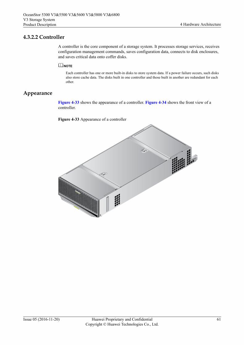
4.3.2.2 ControllerA controller is the core component of a storage system. It processes storage services, receivesconfiguration management commands, saves configuration data, connects to disk enclosures,and saves critical data onto coffer disks.
NOTE
Each controller has one or more built-in disks to store system data. If a power failure occurs, such disksalso store cache data. The disks built in one controller and those built in another are redundant for eachother.
AppearanceFigure 4-33 shows the appearance of a controller. Figure 4-34 shows the front view of acontroller.
Figure 4-33 Appearance of a controller
OceanStor 5300 V3&5500 V3&5600 V3&5800 V3&6800V3 Storage SystemProduct Description 4 Hardware Architecture
Issue 05 (2016-11-20) Huawei Proprietary and ConfidentialCopyright © Huawei Technologies Co., Ltd.
61
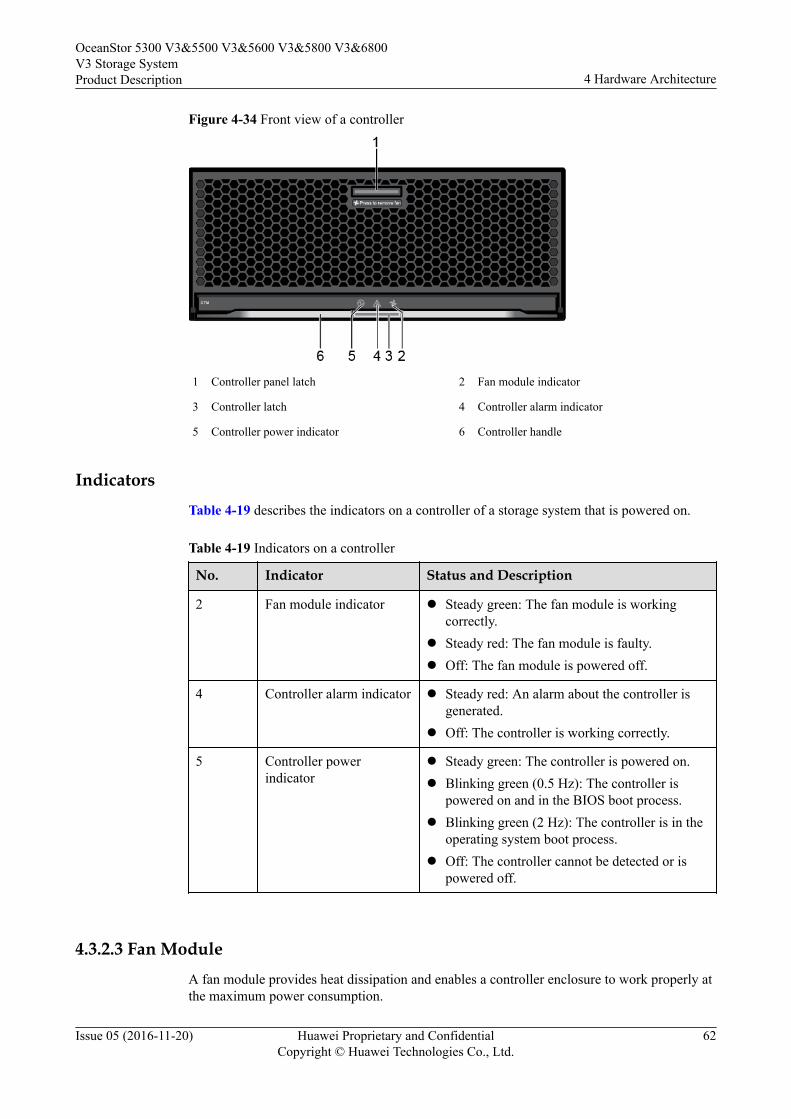
Figure 4-34 Front view of a controller
1 Controller panel latch 2 Fan module indicator
3 Controller latch 4 Controller alarm indicator
5 Controller power indicator 6 Controller handle
IndicatorsTable 4-19 describes the indicators on a controller of a storage system that is powered on.
Table 4-19 Indicators on a controller
No. Indicator Status and Description
2 Fan module indicator l Steady green: The fan module is workingcorrectly.
l Steady red: The fan module is faulty.l Off: The fan module is powered off.
4 Controller alarm indicator l Steady red: An alarm about the controller isgenerated.
l Off: The controller is working correctly.
5 Controller powerindicator
l Steady green: The controller is powered on.l Blinking green (0.5 Hz): The controller is
powered on and in the BIOS boot process.l Blinking green (2 Hz): The controller is in the
operating system boot process.l Off: The controller cannot be detected or is
powered off.
4.3.2.3 Fan ModuleA fan module provides heat dissipation and enables a controller enclosure to work properly atthe maximum power consumption.
OceanStor 5300 V3&5500 V3&5600 V3&5800 V3&6800V3 Storage SystemProduct Description 4 Hardware Architecture
Issue 05 (2016-11-20) Huawei Proprietary and ConfidentialCopyright © Huawei Technologies Co., Ltd.
62
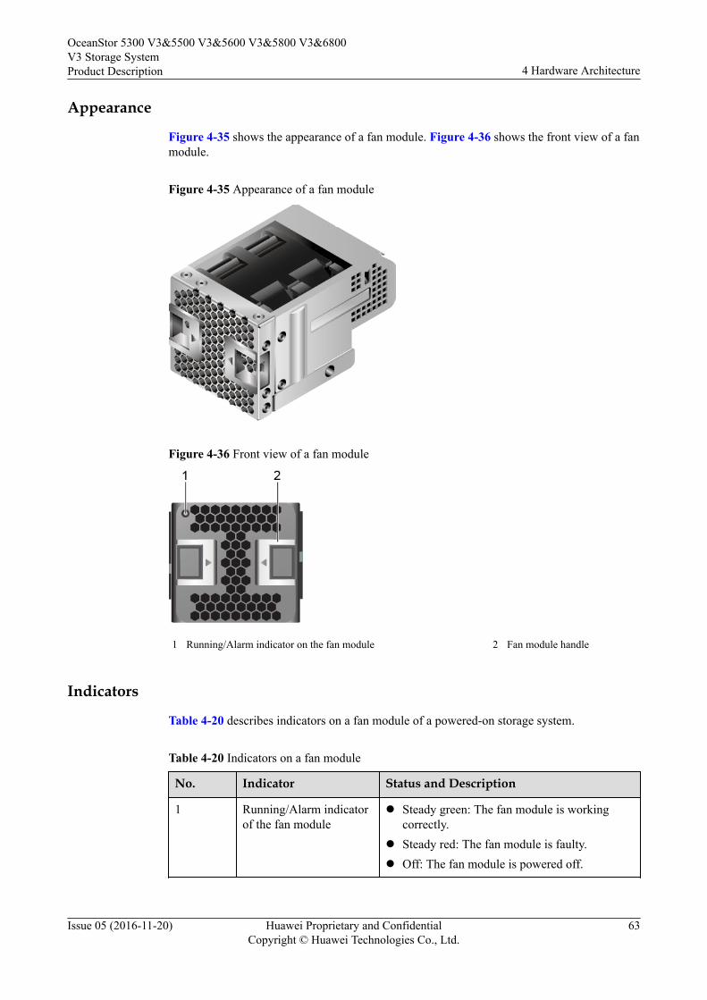
Appearance
Figure 4-35 shows the appearance of a fan module. Figure 4-36 shows the front view of a fanmodule.
Figure 4-35 Appearance of a fan module
Figure 4-36 Front view of a fan module
1 Running/Alarm indicator on the fan module 2 Fan module handle
Indicators
Table 4-20 describes indicators on a fan module of a powered-on storage system.
Table 4-20 Indicators on a fan module
No. Indicator Status and Description
1 Running/Alarm indicatorof the fan module
l Steady green: The fan module is workingcorrectly.
l Steady red: The fan module is faulty.l Off: The fan module is powered off.
OceanStor 5300 V3&5500 V3&5600 V3&5800 V3&6800V3 Storage SystemProduct Description 4 Hardware Architecture
Issue 05 (2016-11-20) Huawei Proprietary and ConfidentialCopyright © Huawei Technologies Co., Ltd.
63
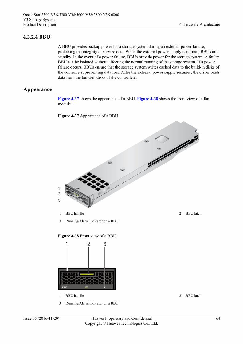
4.3.2.4 BBU
A BBU provides backup power for a storage system during an external power failure,protecting the integrity of service data. When the external power supply is normal, BBUs arestandby. In the event of a power failure, BBUs provide power for the storage system. A faultyBBU can be isolated without affecting the normal running of the storage system. If a powerfailure occurs, BBUs ensure that the storage system writes cached data to the build-in disks ofthe controllers, preventing data loss. After the external power supply resumes, the driver readsdata from the build-in disks of the controllers.
Appearance
Figure 4-37 shows the appearance of a BBU. Figure 4-38 shows the front view of a fanmodule.
Figure 4-37 Appearance of a BBU
1 BBU handle 2 BBU latch
3 Running/Alarm indicator on a BBU
Figure 4-38 Front view of a BBU
1 BBU handle 2 BBU latch
3 Running/Alarm indicator on a BBU
OceanStor 5300 V3&5500 V3&5600 V3&5800 V3&6800V3 Storage SystemProduct Description 4 Hardware Architecture
Issue 05 (2016-11-20) Huawei Proprietary and ConfidentialCopyright © Huawei Technologies Co., Ltd.
64
IndicatorTable 4-21 describes the indicator on a BBU of a storage system that is powered on.
Table 4-21 Indicator on a BBU
No. Indicator Status and Description
3 Running/Alarm indicatoron a BBU
l Steady green: The BBU is fully charged.l Blinking green (1 Hz): The BBU is being
charged.l Blinking green (4 Hz): The BBU is being
discharged.l Steady red: The BBU is faulty.l Off: The interface module is powered off or
hot swappable.
4.3.2.5 16 Gbit/s Fibre Channel Interface ModuleInterface modules connect storage devices to application servers.
FunctionA 16 Gbit/s Fibre Channel interface module provides two 16 Gbit/s Fibre Channel ports.These ports are service ports used to connect a storage system to application servers andreceive data read/write requests from application servers. If the data transfer rate of anapplication server connected to such a port is lower than the port rate and the port mode is setto autonegotiation, the port automatically adjusts its rate to ensure the connectivity of the datatransfer channel and the consistency of the data transfer rate. If the port rate is manually setbut inconsistent with the data transfer rate of the connected application server, the connectionis interrupted.
PortsFigure 4-39 shows the appearance of a 16 Gbit/s Fibre Channel interface module.
OceanStor 5300 V3&5500 V3&5600 V3&5800 V3&6800V3 Storage SystemProduct Description 4 Hardware Architecture
Issue 05 (2016-11-20) Huawei Proprietary and ConfidentialCopyright © Huawei Technologies Co., Ltd.
65

Figure 4-39 16 Gbit/s Fibre Channel interface module
1 Power indicator/Hot Swap button on the module 2 16 Gbit/s Fibre Channel port
3 Link/Speed indicator of a 16 Gbit/s Fibre Channel port 4 Interface module handle
IndicatorsTable 4-22 describes indicators on a 16 Gbit/s Fibre Channel interface module of a storagesystem that is powered on.
Table 4-22 Indicators on a 16 Gbit/s Fibre Channel interface module
No. Indicator Status and Description
1 Power indicator/HotSwap button on theinterface module
l Steady green: The interface module isworking correctly.
l Blinking green: There is a hot swap request tothe module.
l Steady red: The module is faulty.l Off: The interface module is powered off or
hot swappable.
OceanStor 5300 V3&5500 V3&5600 V3&5800 V3&6800V3 Storage SystemProduct Description 4 Hardware Architecture
Issue 05 (2016-11-20) Huawei Proprietary and ConfidentialCopyright © Huawei Technologies Co., Ltd.
66

No. Indicator Status and Description
3 Link/Speed indicator ofthe 16 Gbit/s FibreChannel port
l Steady blue: The data transfer rate betweenthe storage system and the application serveris 16 Gbit/s.
l Blinking blue: Data is being transferred.l Steady green: The data transfer rate between
the storage system and the application serveris 8 Gbit/s or 4 Gbit/s.
l Blinking green: Data is being transferred.l Steady red: The port is faulty.l Off: The link to the port is down.
4.3.2.6 8 Gbit/s Fibre Channel Interface ModuleInterface modules connect storage devices to application servers.
FunctionAn 8 Gbit/s Fibre Channel interface module provides four 8 Gbit/s Fibre Channel ports. Theseports are service ports used to connect a storage system to application servers and receive dataread/write requests from application servers. If the data transfer rate of an application serverconnected to such a port is lower than the port rate and the port mode is set to autonegotiation,the port automatically adjusts its rate to ensure the connectivity of the data transfer channeland the consistency of the data transfer rate. If the port rate is manually set but inconsistentwith the data transfer rate of the connected application server, the connection is interrupted.
PortsFigure 4-40 shows the appearance of an 8 Gbit/s Fibre Channel interface module.
OceanStor 5300 V3&5500 V3&5600 V3&5800 V3&6800V3 Storage SystemProduct Description 4 Hardware Architecture
Issue 05 (2016-11-20) Huawei Proprietary and ConfidentialCopyright © Huawei Technologies Co., Ltd.
67

Figure 4-40 8 Gbit/s Fibre Channel interface module
1 Power indicator/Hot Swap button on the module 2 8 Gbit/s Fibre Channel port
3 Link/Speed indicator of an 8 Gbit/s Fibre Channel port 4 Module handle
IndicatorsTable 4-23 describes the indicators on an 8 Gbit/s Fibre Channel interface module of astorage system that is powered on.
Table 4-23 Indicators on an 8 Gbit/s Fibre Channel interface module
No. Indicators Status and Description
1 Power indicator/HotSwap button on themodule
l Steady green: The interface module isworking correctly.
l Blinking green: The interface modulereceives a hot swap request.
l Steady red: The interface module is faulty.l Off: The interface module is powered off or
hot swappable.
OceanStor 5300 V3&5500 V3&5600 V3&5800 V3&6800V3 Storage SystemProduct Description 4 Hardware Architecture
Issue 05 (2016-11-20) Huawei Proprietary and ConfidentialCopyright © Huawei Technologies Co., Ltd.
68

No. Indicators Status and Description
3 Link/Speed indicator ofan 8 Gbit/s Fibre Channelport
l Steady blue: The data transfer rate betweenthe storage system and the application serveris 8 Gbit/s.
l Blinking blue: Data is being transferred.l Steady green: The data transfer rate between
the storage system and the application serveris 4 or 2 Gbit/s.
l Blinking green: Data is being transferred.l Steady red: The port is faulty.l Off: The link to the port is down.
4.3.2.7 10 Gbit/s FCoE Interface Module (Two Ports)Interface modules connect storage devices to application servers.
FunctionA 10 Gbit/s FCoE interface module provides two 10 Gbit/s FCoE ports. These ports areservice ports used to connect a storage system to application servers and receive data read/write requests from application servers.
PortsFigure 4-41 shows the appearance of a 10 Gbit/s FCoE interface module.
NOTE
l A 10 Gbit/s two-port FCoE interface module only supports direct connection networking.
l You are not advised to run iSCSI and FCoE protocols simultaneously for a 10 Gbit/s two-portFCoE interface module.
OceanStor 5300 V3&5500 V3&5600 V3&5800 V3&6800V3 Storage SystemProduct Description 4 Hardware Architecture
Issue 05 (2016-11-20) Huawei Proprietary and ConfidentialCopyright © Huawei Technologies Co., Ltd.
69

Figure 4-41 10 Gbit/s FCoE interface module
1 Power indicator/Hot Swap button on the module 2 10 Gbit/s FCoE port
3 Link/Speed indicator of a 10 Gbit/s FCoE port 4 Module handle
IndicatorsTable 4-24 describes the indicators on a 10 Gbit/s FCoE interface module of a storage systemthat is powered on.
Table 4-24 Indicators on a 10 Gbit/s FCoE interface module
No. Indicators Status and Description
1 Power indicator/HotSwap button on themodule
l Steady green: The interface module isworking correctly.
l Blinking green: The interface module receivesa hot swap request.
l Steady red: The interface module is faulty.l Off: The interface module is powered off or
hot swappable.
3 Link/Speed indicator of a10 Gbit/s FCoE port
l Steady blue: The data transfer rate betweenthe storage system and the application serveris 10 Gbit/s.
l Blinking blue: Data is being transferred.l Steady red: The port is faulty.l Off: The link to the port is down.
4.3.2.8 10GE Electrical Interface ModuleInterface modules connect storage devices to application servers.
OceanStor 5300 V3&5500 V3&5600 V3&5800 V3&6800V3 Storage SystemProduct Description 4 Hardware Architecture
Issue 05 (2016-11-20) Huawei Proprietary and ConfidentialCopyright © Huawei Technologies Co., Ltd.
70
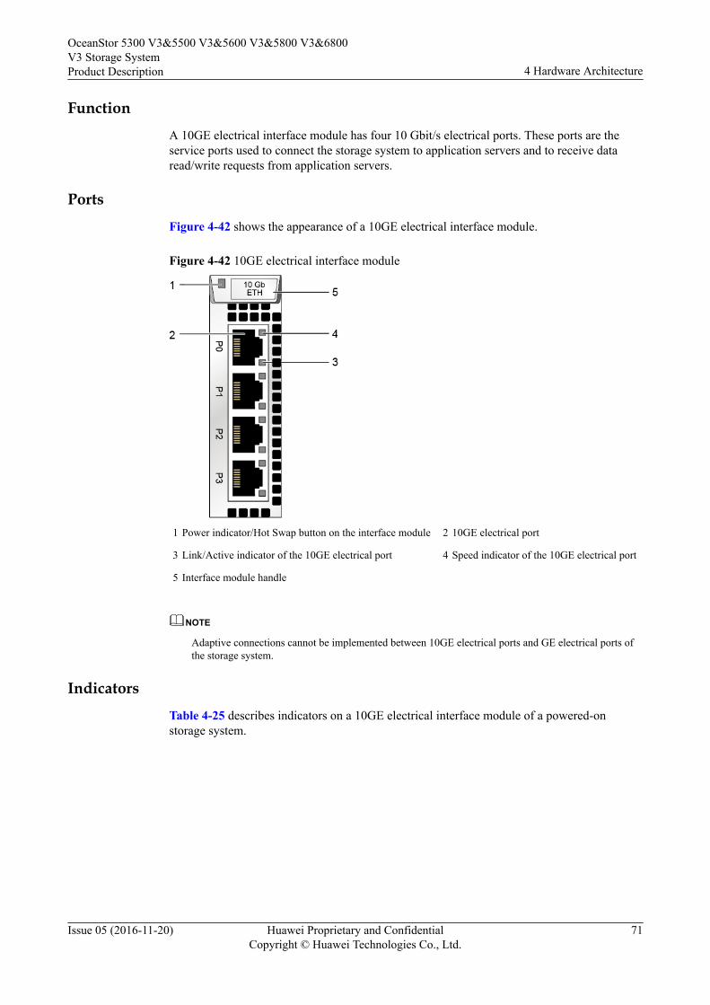
FunctionA 10GE electrical interface module has four 10 Gbit/s electrical ports. These ports are theservice ports used to connect the storage system to application servers and to receive dataread/write requests from application servers.
PortsFigure 4-42 shows the appearance of a 10GE electrical interface module.
Figure 4-42 10GE electrical interface module
1 Power indicator/Hot Swap button on the interface module 2 10GE electrical port
3 Link/Active indicator of the 10GE electrical port 4 Speed indicator of the 10GE electrical port
5 Interface module handle
NOTE
Adaptive connections cannot be implemented between 10GE electrical ports and GE electrical ports ofthe storage system.
IndicatorsTable 4-25 describes indicators on a 10GE electrical interface module of a powered-onstorage system.
OceanStor 5300 V3&5500 V3&5600 V3&5800 V3&6800V3 Storage SystemProduct Description 4 Hardware Architecture
Issue 05 (2016-11-20) Huawei Proprietary and ConfidentialCopyright © Huawei Technologies Co., Ltd.
71
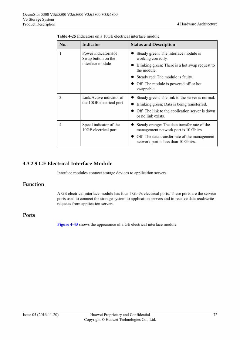
Table 4-25 Indicators on a 10GE electrical interface module
No. Indicator Status and Description
1 Power indicator/HotSwap button on theinterface module
l Steady green: The interface module isworking correctly.
l Blinking green: There is a hot swap request tothe module.
l Steady red: The module is faulty.l Off: The module is powered off or hot
swappable.
3 Link/Active indicator ofthe 10GE electrical port
l Steady green: The link to the server is normal.l Blinking green: Data is being transferred.l Off: The link to the application server is down
or no link exists.
4 Speed indicator of the10GE electrical port
l Steady orange: The data transfer rate of themanagement network port is 10 Gbit/s.
l Off: The data transfer rate of the managementnetwork port is less than 10 Gbit/s.
4.3.2.9 GE Electrical Interface ModuleInterface modules connect storage devices to application servers.
FunctionA GE electrical interface module has four 1 Gbit/s electrical ports. These ports are the serviceports used to connect the storage system to application servers and to receive data read/writerequests from application servers.
PortsFigure 4-43 shows the appearance of a GE electrical interface module.
OceanStor 5300 V3&5500 V3&5600 V3&5800 V3&6800V3 Storage SystemProduct Description 4 Hardware Architecture
Issue 05 (2016-11-20) Huawei Proprietary and ConfidentialCopyright © Huawei Technologies Co., Ltd.
72

Figure 4-43 GE electrical interface module
1 Power indicator/Hot Swap button on the interface module 2 GE electrical port
3 Link/Active indicator of the GE electrical port 4 Speed indicator of the GE electrical port
5 Interface module handle
Indicators
Table 4-26 describes indicators on a GE electrical interface module of a powered-on storagesystem.
Table 4-26 Indicators on a GE electrical interface module
No. Indicator Status and Description
1 Power indicator/HotSwap button on theinterface module
l Steady green: The interface module isworking correctly.
l Blinking green: There is a hot swap request tothe module.
l Steady red: The module is faulty.l Off: The interface module is powered off or
hot swappable.
3 Link/Active indicator ofthe GE electrical port
l Steady green: The link to the server is normal.l Blinking green: Data is being transferred.l Off: The link to the application server is down
or no link exists.
4 Speed indicator of the GEelectrical port
l Steady orange: The data transfer rate betweenthe storage system and the application serveris 1 Gbit/s.
l Off: The data transfer rate between thestorage system and the application server isless than 1 Gbit/s.
OceanStor 5300 V3&5500 V3&5600 V3&5800 V3&6800V3 Storage SystemProduct Description 4 Hardware Architecture
Issue 05 (2016-11-20) Huawei Proprietary and ConfidentialCopyright © Huawei Technologies Co., Ltd.
73
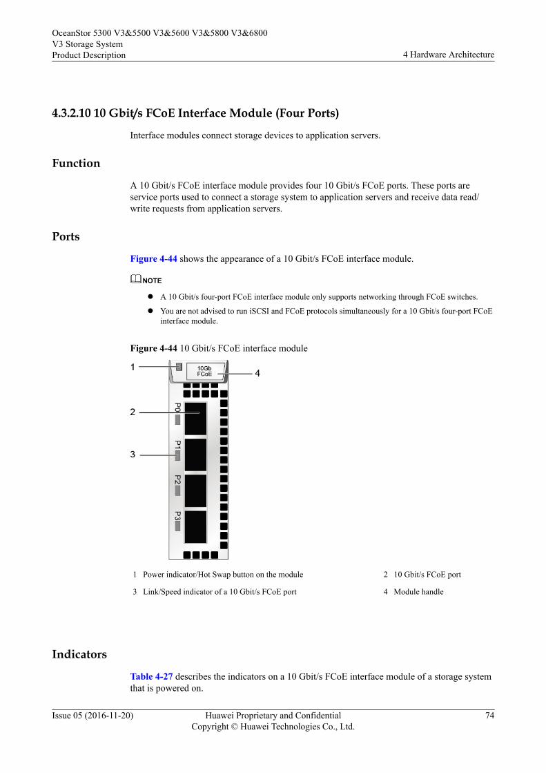
4.3.2.10 10 Gbit/s FCoE Interface Module (Four Ports)
Interface modules connect storage devices to application servers.
Function
A 10 Gbit/s FCoE interface module provides four 10 Gbit/s FCoE ports. These ports areservice ports used to connect a storage system to application servers and receive data read/write requests from application servers.
Ports
Figure 4-44 shows the appearance of a 10 Gbit/s FCoE interface module.
NOTE
l A 10 Gbit/s four-port FCoE interface module only supports networking through FCoE switches.
l You are not advised to run iSCSI and FCoE protocols simultaneously for a 10 Gbit/s four-port FCoEinterface module.
Figure 4-44 10 Gbit/s FCoE interface module
1 Power indicator/Hot Swap button on the module 2 10 Gbit/s FCoE port
3 Link/Speed indicator of a 10 Gbit/s FCoE port 4 Module handle
Indicators
Table 4-27 describes the indicators on a 10 Gbit/s FCoE interface module of a storage systemthat is powered on.
OceanStor 5300 V3&5500 V3&5600 V3&5800 V3&6800V3 Storage SystemProduct Description 4 Hardware Architecture
Issue 05 (2016-11-20) Huawei Proprietary and ConfidentialCopyright © Huawei Technologies Co., Ltd.
74
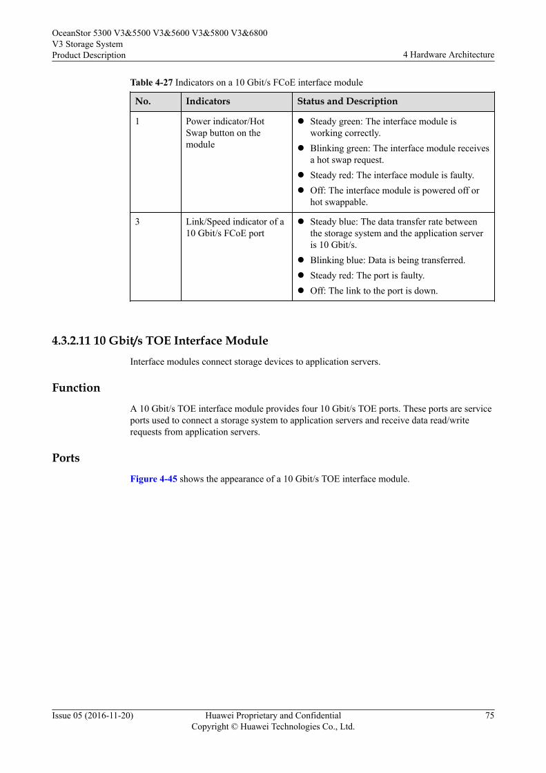
Table 4-27 Indicators on a 10 Gbit/s FCoE interface module
No. Indicators Status and Description
1 Power indicator/HotSwap button on themodule
l Steady green: The interface module isworking correctly.
l Blinking green: The interface module receivesa hot swap request.
l Steady red: The interface module is faulty.l Off: The interface module is powered off or
hot swappable.
3 Link/Speed indicator of a10 Gbit/s FCoE port
l Steady blue: The data transfer rate betweenthe storage system and the application serveris 10 Gbit/s.
l Blinking blue: Data is being transferred.l Steady red: The port is faulty.l Off: The link to the port is down.
4.3.2.11 10 Gbit/s TOE Interface ModuleInterface modules connect storage devices to application servers.
FunctionA 10 Gbit/s TOE interface module provides four 10 Gbit/s TOE ports. These ports are serviceports used to connect a storage system to application servers and receive data read/writerequests from application servers.
PortsFigure 4-45 shows the appearance of a 10 Gbit/s TOE interface module.
OceanStor 5300 V3&5500 V3&5600 V3&5800 V3&6800V3 Storage SystemProduct Description 4 Hardware Architecture
Issue 05 (2016-11-20) Huawei Proprietary and ConfidentialCopyright © Huawei Technologies Co., Ltd.
75
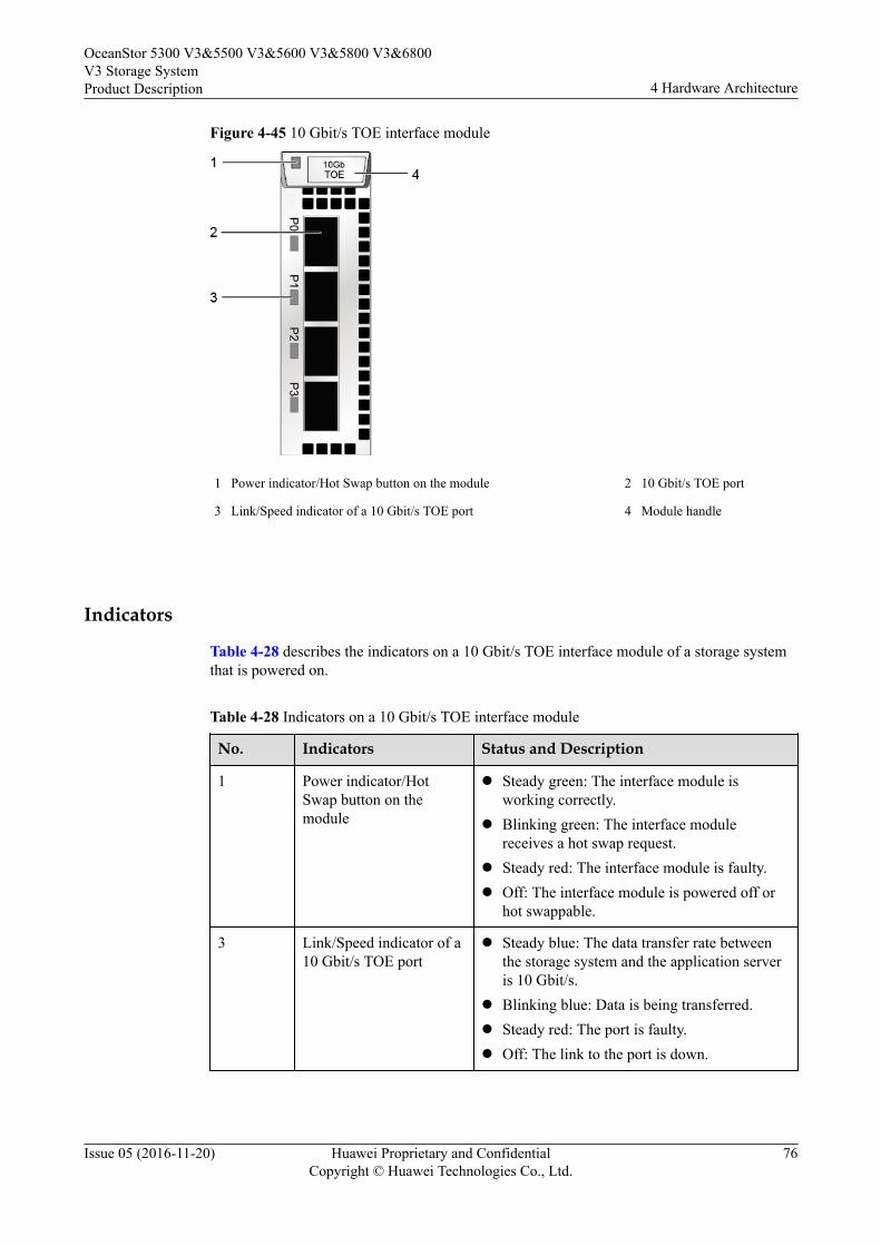
Figure 4-45 10 Gbit/s TOE interface module
1 Power indicator/Hot Swap button on the module 2 10 Gbit/s TOE port
3 Link/Speed indicator of a 10 Gbit/s TOE port 4 Module handle
Indicators
Table 4-28 describes the indicators on a 10 Gbit/s TOE interface module of a storage systemthat is powered on.
Table 4-28 Indicators on a 10 Gbit/s TOE interface module
No. Indicators Status and Description
1 Power indicator/HotSwap button on themodule
l Steady green: The interface module isworking correctly.
l Blinking green: The interface modulereceives a hot swap request.
l Steady red: The interface module is faulty.l Off: The interface module is powered off or
hot swappable.
3 Link/Speed indicator of a10 Gbit/s TOE port
l Steady blue: The data transfer rate betweenthe storage system and the application serveris 10 Gbit/s.
l Blinking blue: Data is being transferred.l Steady red: The port is faulty.l Off: The link to the port is down.
OceanStor 5300 V3&5500 V3&5600 V3&5800 V3&6800V3 Storage SystemProduct Description 4 Hardware Architecture
Issue 05 (2016-11-20) Huawei Proprietary and ConfidentialCopyright © Huawei Technologies Co., Ltd.
76

4.3.2.12 56 Gbit/s IB Interface ModuleInterface modules connect storage devices to application servers.
FunctionA 56 Gbit/s IB interface module provides two 4 x 14 Gbit/s IB ports. Both are the serviceports used to connect to application servers and to receive data read/write requests fromapplication servers.
InterfaceFigure 4-46 shows the appearance of a 56 Gbit/s IB interface module.
Figure 4-46 56 Gbit/s IB interface module
1 Power indicator/Hot Swap button of the module 2 56 Gbit/s IB port Link indicator
3 56 Gbit/s IB port Active indicator 4 56 Gbit/s IB port
5 Module handle
IndicatorsTable 4-29 describes the states of indicators and their meanings on a 56 Gbit/s IB interfacemodule after the storage device is powered on.
OceanStor 5300 V3&5500 V3&5600 V3&5800 V3&6800V3 Storage SystemProduct Description 4 Hardware Architecture
Issue 05 (2016-11-20) Huawei Proprietary and ConfidentialCopyright © Huawei Technologies Co., Ltd.
77
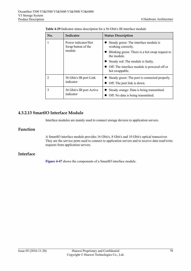
Table 4-29 Indicator status description for a 56 Gbit/s IB interface module
No. Indicator Status Description
1 Power indicator/HotSwap button of themodule
l Steady green: The interface module isworking correctly.
l Blinking green: There is a hot swap request tothe module.
l Steady red: The module is faulty.l Off: The interface module is powered off or
hot swappable.
2 56 Gbit/s IB port Linkindicator
l Steady green: The port is connected properly.l Off: The port link is down.
3 56 Gbit/s IB port Activeindicator
l Steady orange: Data is being transmitted.l Off: No data is being transmitted.
4.3.2.13 SmartIO Interface ModuleInterface modules are mainly used to connect storage devices to application servers.
FunctionA SmartIO interface module provides 16 Gbit/s, 8 Gbit/s and 10 Gbit/s optical transceiver.They are the service ports used to connect to application servers and to receive data read/writerequests from application servers.
InterfaceFigure 4-47 shows the components of a SmartIO interface module.
OceanStor 5300 V3&5500 V3&5600 V3&5800 V3&6800V3 Storage SystemProduct Description 4 Hardware Architecture
Issue 05 (2016-11-20) Huawei Proprietary and ConfidentialCopyright © Huawei Technologies Co., Ltd.
78
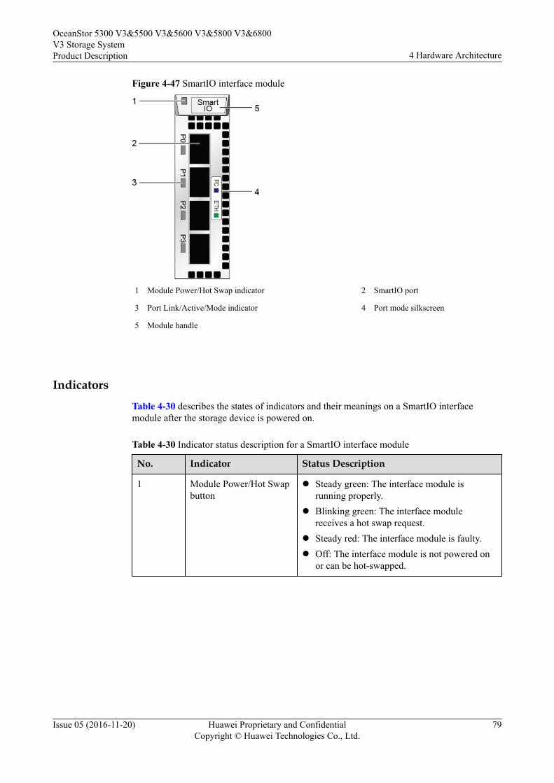
Figure 4-47 SmartIO interface module
1 Module Power/Hot Swap indicator 2 SmartIO port
3 Port Link/Active/Mode indicator 4 Port mode silkscreen
5 Module handle
IndicatorsTable 4-30 describes the states of indicators and their meanings on a SmartIO interfacemodule after the storage device is powered on.
Table 4-30 Indicator status description for a SmartIO interface module
No. Indicator Status Description
1 Module Power/Hot Swapbutton
l Steady green: The interface module isrunning properly.
l Blinking green: The interface modulereceives a hot swap request.
l Steady red: The interface module is faulty.l Off: The interface module is not powered on
or can be hot-swapped.
OceanStor 5300 V3&5500 V3&5600 V3&5800 V3&6800V3 Storage SystemProduct Description 4 Hardware Architecture
Issue 05 (2016-11-20) Huawei Proprietary and ConfidentialCopyright © Huawei Technologies Co., Ltd.
79

No. Indicator Status Description
3 Port Link/Active/Modeindicator
l Blinking blue slowly: The interface module isworking in FC mode, and the port link isdown.
l Blinking blue quickly: The interface moduleis working in FC mode, and data is beingtransmitted.
l Steady blue: The interface module is workingin FC mode, the port link is up, and no data isbeing transmitted.
l Blinking green slowly: The interface moduleis working in ETH mode, and the port link isdown.
l Blinking green quickly: The interface moduleis working in ETH mode, and data is beingtransmitted.
l Steady green: The interface module isworking in ETH mode, the port link is up, andno data is being transmitted.
l Steady red: The port is faulty.l Blinking red: The port is being located.l Off: The port is not powered on.
NOTE
l If the mode of the SmartIO port is set to FCoE/iSCSI or Cluster on the software interface, the portindicator is in ETH mode. The SmartIO port need to configure with 10 Gbit/s optical modules.
l If the mode of the SmartIO port is set to FC on the software interface, the port indicator is in FCmode. The SmartIO port need to configure with 8 Gbit/s or 16 Gbit/s optical modules.
l Connect a network only through FCoE switches when the SmartIO interface module is set to FCoE/iSCSI and the host uses the FCoE protocol. The SmartIO port need to configure with 10 Gbit/soptical modules.
4.3.2.14 Smart ACC Module (Applicable to V300R003C00/V300R003C10)
Smart ACC modules are mainly used to improve system performance.
Function
Smart ACC modules can concurrently provide functions such as fixed-length deduplication,fingerprint computing, and hardware acceleration for GZIP compression and decompression,reducing CPU load and promoting deduplication and compression performance.
Interface
Figure 4-48 shows the components of a Smart ACC module.
OceanStor 5300 V3&5500 V3&5600 V3&5800 V3&6800V3 Storage SystemProduct Description 4 Hardware Architecture
Issue 05 (2016-11-20) Huawei Proprietary and ConfidentialCopyright © Huawei Technologies Co., Ltd.
80
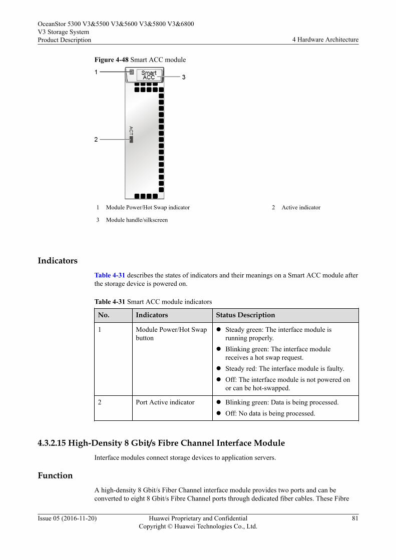
Figure 4-48 Smart ACC module
1 Module Power/Hot Swap indicator 2 Active indicator
3 Module handle/silkscreen
IndicatorsTable 4-31 describes the states of indicators and their meanings on a Smart ACC module afterthe storage device is powered on.
Table 4-31 Smart ACC module indicators
No. Indicators Status Description
1 Module Power/Hot Swapbutton
l Steady green: The interface module isrunning properly.
l Blinking green: The interface modulereceives a hot swap request.
l Steady red: The interface module is faulty.l Off: The interface module is not powered on
or can be hot-swapped.
2 Port Active indicator l Blinking green: Data is being processed.l Off: No data is being processed.
4.3.2.15 High-Density 8 Gbit/s Fibre Channel Interface ModuleInterface modules connect storage devices to application servers.
FunctionA high-density 8 Gbit/s Fiber Channel interface module provides two ports and can beconverted to eight 8 Gbit/s Fibre Channel ports through dedicated fiber cables. These Fibre
OceanStor 5300 V3&5500 V3&5600 V3&5800 V3&6800V3 Storage SystemProduct Description 4 Hardware Architecture
Issue 05 (2016-11-20) Huawei Proprietary and ConfidentialCopyright © Huawei Technologies Co., Ltd.
81
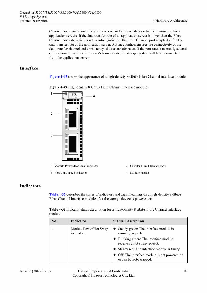
Channel ports can be used for a storage system to receive data exchange commands fromapplication servers. If the data transfer rate of an application server is lower than the FibreChannel port rate which is set to autonegotiation, the Fibre Channel port adapts itself to thedata transfer rate of the application server. Autonegotiation ensures the connectivity of thedata transfer channel and consistency of data transfer rates. If the port rate is manually set anddiffers from the application server's transfer rate, the storage system will be disconnectedfrom the application server.
Interface
Figure 4-49 shows the appearance of a high-density 8 Gbit/s Fibre Channel interface module.
Figure 4-49 High-density 8 Gbit/s Fibre Channel interface module
1 Module Power/Hot Swap indicator 2 8 Gbit/s Fibre Channel ports
3 Port Link/Speed indicator 4 Module handle
Indicators
Table 4-32 describes the states of indicators and their meanings on a high-density 8 Gbit/sFibre Channel interface module after the storage device is powered on.
Table 4-32 Indicator status description for a high-density 8 Gbit/s Fibre Channel interfacemodule
No. Indicator Status Description
1 Module Power/Hot Swapindicator
l Steady green: The interface module isrunning properly.
l Blinking green: The interface modulereceives a hot swap request.
l Steady red: The interface module is faulty.l Off: The interface module is not powered on
or can be hot-swapped.
OceanStor 5300 V3&5500 V3&5600 V3&5800 V3&6800V3 Storage SystemProduct Description 4 Hardware Architecture
Issue 05 (2016-11-20) Huawei Proprietary and ConfidentialCopyright © Huawei Technologies Co., Ltd.
82

No. Indicator Status Description
3 Link/Speed indicator ofthe 8 Gbit/s FibreChannel host port
l Steady blue: Data is being transmittedbetween the storage system and theapplication server at a rate of 8 Gbit/s.
l Blinking blue: Data is being transferred.l Steady green: Data is being transmitted
between the storage system and theapplication server at a rate of 4 Gbit/s or 2Gbit/s.
l Blinking green: Data is being transmitted.l Steady red: The port is faulty.l Off: The port link is down.
4.3.2.16 12 Gbit/s SAS Expansion ModuleAn expansion module provides expansion ports that are used for communication between acontroller enclosure and a disk enclosure. The module transfers data between a controllerenclosure and a disk enclosure.
FunctionA SAS interface module provides four 4 x 12 Gbit/s mini SAS HD expansion ports thatprovide connectivity to disk enclosures. The SAS interface module connects to the back-endstorage array of the storage system through a mini SAS HD cable. When the transfer rate ofthe connected device is less than that of the expansion port, the expansion port automaticallyadjusts the transfer rate to that of the connected device to ensure the connectivity of the datatransfer channel.
PortsFigure 4-50 shows the appearance of a 12 Gbit/s SAS expansion module.
OceanStor 5300 V3&5500 V3&5600 V3&5800 V3&6800V3 Storage SystemProduct Description 4 Hardware Architecture
Issue 05 (2016-11-20) Huawei Proprietary and ConfidentialCopyright © Huawei Technologies Co., Ltd.
83

Figure 4-50 12 Gbit/s SAS expansion module
1 Power indicator/Hot Swap button of the module 2 Mini SAS HD expansion port
3 Indicator of the mini SAS HD expansion port 4 Module handle
IndicatorsTable 4-33 describes indicators on a 12 Gbit/s SAS expansion module of a powered-onstorage system.
Table 4-33 Indicators on a 12 Gbit/s SAS expansion module
No. Indicator Status and Description
1 Power indicator/HotSwap button of themodule
l Steady green: The interface module isworking correctly.
l Blinking green: There is a hot swap request tothe module.
l Steady red: The module is faulty.l Off: The interface module is powered off or
hot swappable.
OceanStor 5300 V3&5500 V3&5600 V3&5800 V3&6800V3 Storage SystemProduct Description 4 Hardware Architecture
Issue 05 (2016-11-20) Huawei Proprietary and ConfidentialCopyright © Huawei Technologies Co., Ltd.
84
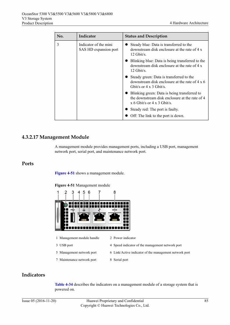
No. Indicator Status and Description
3 Indicator of the miniSAS HD expansion port
l Steady blue: Data is transferred to thedownstream disk enclosure at the rate of 4 x12 Gbit/s.
l Blinking blue: Data is being transferred to thedownstream disk enclosure at the rate of 4 x12 Gbit/s.
l Steady green: Data is transferred to thedownstream disk enclosure at the rate of 4 x 6Gbit/s or 4 x 3 Gbit/s.
l Blinking green: Data is being transferred tothe downstream disk enclosure at the rate of 4x 6 Gbit/s or 4 x 3 Gbit/s.
l Steady red: The port is faulty.l Off: The link to the port is down.
4.3.2.17 Management Module
A management module provides management ports, including a USB port, managementnetwork port, serial port, and maintenance network port.
Ports
Figure 4-51 shows a management module.
Figure 4-51 Management module
1 Management module handle 2 Power indicator
3 USB port 4 Speed indicator of the management network port
5 Management network port 6 Link/Active indicator of the management network port
7 Maintenance network port 8 Serial port
Indicators
Table 4-34 describes the indicators on a management module of a storage system that ispowered on.
OceanStor 5300 V3&5500 V3&5600 V3&5800 V3&6800V3 Storage SystemProduct Description 4 Hardware Architecture
Issue 05 (2016-11-20) Huawei Proprietary and ConfidentialCopyright © Huawei Technologies Co., Ltd.
85
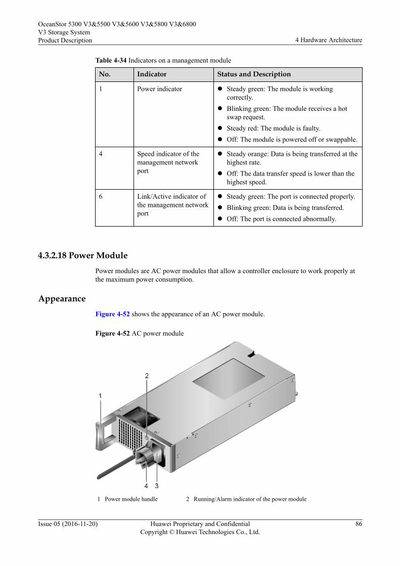
Table 4-34 Indicators on a management module
No. Indicator Status and Description
1 Power indicator l Steady green: The module is workingcorrectly.
l Blinking green: The module receives a hotswap request.
l Steady red: The module is faulty.l Off: The module is powered off or swappable.
4 Speed indicator of themanagement networkport
l Steady orange: Data is being transferred at thehighest rate.
l Off: The data transfer speed is lower than thehighest speed.
6 Link/Active indicator ofthe management networkport
l Steady green: The port is connected properly.l Blinking green: Data is being transferred.l Off: The port is connected abnormally.
4.3.2.18 Power Module
Power modules are AC power modules that allow a controller enclosure to work properly atthe maximum power consumption.
Appearance
Figure 4-52 shows the appearance of an AC power module.
Figure 4-52 AC power module
1 Power module handle 2 Running/Alarm indicator of the power module
OceanStor 5300 V3&5500 V3&5600 V3&5800 V3&6800V3 Storage SystemProduct Description 4 Hardware Architecture
Issue 05 (2016-11-20) Huawei Proprietary and ConfidentialCopyright © Huawei Technologies Co., Ltd.
86
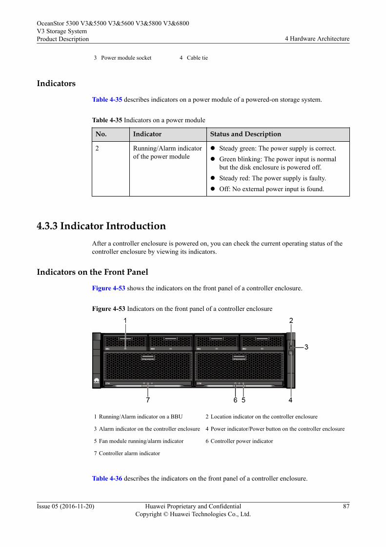
3 Power module socket 4 Cable tie
Indicators
Table 4-35 describes indicators on a power module of a powered-on storage system.
Table 4-35 Indicators on a power module
No. Indicator Status and Description
2 Running/Alarm indicatorof the power module
l Steady green: The power supply is correct.l Green blinking: The power input is normal
but the disk enclosure is powered off.l Steady red: The power supply is faulty.l Off: No external power input is found.
4.3.3 Indicator IntroductionAfter a controller enclosure is powered on, you can check the current operating status of thecontroller enclosure by viewing its indicators.
Indicators on the Front Panel
Figure 4-53 shows the indicators on the front panel of a controller enclosure.
Figure 4-53 Indicators on the front panel of a controller enclosure
1 Running/Alarm indicator on a BBU 2 Location indicator on the controller enclosure
3 Alarm indicator on the controller enclosure 4 Power indicator/Power button on the controller enclosure
5 Fan module running/alarm indicator 6 Controller power indicator
7 Controller alarm indicator
Table 4-36 describes the indicators on the front panel of a controller enclosure.
OceanStor 5300 V3&5500 V3&5600 V3&5800 V3&6800V3 Storage SystemProduct Description 4 Hardware Architecture
Issue 05 (2016-11-20) Huawei Proprietary and ConfidentialCopyright © Huawei Technologies Co., Ltd.
87
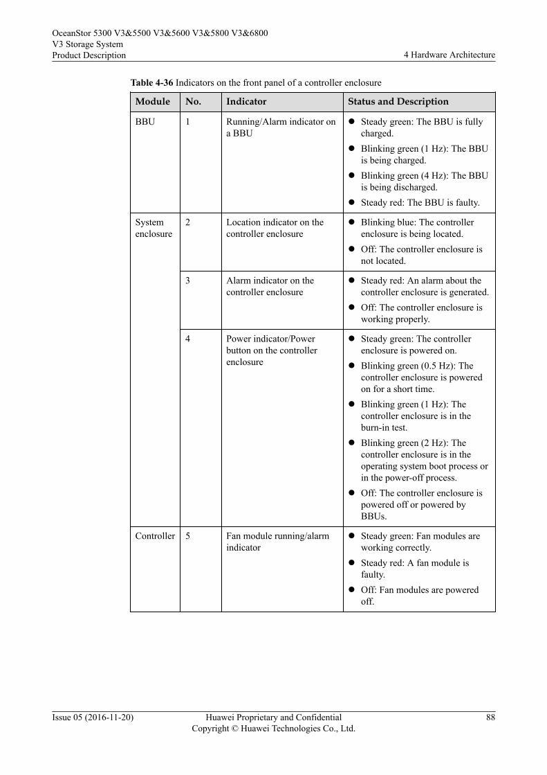
Table 4-36 Indicators on the front panel of a controller enclosure
Module No. Indicator Status and Description
BBU 1 Running/Alarm indicator ona BBU
l Steady green: The BBU is fullycharged.
l Blinking green (1 Hz): The BBUis being charged.
l Blinking green (4 Hz): The BBUis being discharged.
l Steady red: The BBU is faulty.
Systemenclosure
2 Location indicator on thecontroller enclosure
l Blinking blue: The controllerenclosure is being located.
l Off: The controller enclosure isnot located.
3 Alarm indicator on thecontroller enclosure
l Steady red: An alarm about thecontroller enclosure is generated.
l Off: The controller enclosure isworking properly.
4 Power indicator/Powerbutton on the controllerenclosure
l Steady green: The controllerenclosure is powered on.
l Blinking green (0.5 Hz): Thecontroller enclosure is poweredon for a short time.
l Blinking green (1 Hz): Thecontroller enclosure is in theburn-in test.
l Blinking green (2 Hz): Thecontroller enclosure is in theoperating system boot process orin the power-off process.
l Off: The controller enclosure ispowered off or powered byBBUs.
Controller 5 Fan module running/alarmindicator
l Steady green: Fan modules areworking correctly.
l Steady red: A fan module isfaulty.
l Off: Fan modules are poweredoff.
OceanStor 5300 V3&5500 V3&5600 V3&5800 V3&6800V3 Storage SystemProduct Description 4 Hardware Architecture
Issue 05 (2016-11-20) Huawei Proprietary and ConfidentialCopyright © Huawei Technologies Co., Ltd.
88
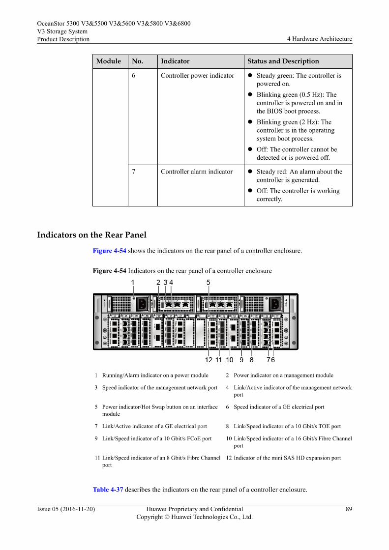
Module No. Indicator Status and Description
6 Controller power indicator l Steady green: The controller ispowered on.
l Blinking green (0.5 Hz): Thecontroller is powered on and inthe BIOS boot process.
l Blinking green (2 Hz): Thecontroller is in the operatingsystem boot process.
l Off: The controller cannot bedetected or is powered off.
7 Controller alarm indicator l Steady red: An alarm about thecontroller is generated.
l Off: The controller is workingcorrectly.
Indicators on the Rear Panel
Figure 4-54 shows the indicators on the rear panel of a controller enclosure.
Figure 4-54 Indicators on the rear panel of a controller enclosure
1 Running/Alarm indicator on a power module 2 Power indicator on a management module
3 Speed indicator of the management network port 4 Link/Active indicator of the management networkport
5 Power indicator/Hot Swap button on an interfacemodule
6 Speed indicator of a GE electrical port
7 Link/Active indicator of a GE electrical port 8 Link/Speed indicator of a 10 Gbit/s TOE port
9 Link/Speed indicator of a 10 Gbit/s FCoE port 10 Link/Speed indicator of a 16 Gbit/s Fibre Channelport
11 Link/Speed indicator of an 8 Gbit/s Fibre Channelport
12 Indicator of the mini SAS HD expansion port
Table 4-37 describes the indicators on the rear panel of a controller enclosure.
OceanStor 5300 V3&5500 V3&5600 V3&5800 V3&6800V3 Storage SystemProduct Description 4 Hardware Architecture
Issue 05 (2016-11-20) Huawei Proprietary and ConfidentialCopyright © Huawei Technologies Co., Ltd.
89

Table 4-37 Indicators on the rear panel of a controller enclosure
Module No. Indicator Status and Description
Powermodule
1 Running/Alarmindicator ona powermodule
l Steady green: The power supply is normal.l Blinking green: The power input is normal but
the device is powered off.l Steady red: The power module is faulty.l Off: No external power input is available.
Managementmodule
2 Powerindicator onamanagementmodule
l Steady green: The module is working correctly.l Blinking green: The module receives a hot swap
request.l Steady red: The module is faulty.l Off: The module is powered off or hot
swappable.
3 Speedindicator ofthemanagementnetwork port
l Steady orange: Data is being transferred at thehighest rate.
l Off: The data transfer speed is lower than thehighest speed.
4 Link/Activeindicator ofthemanagementnetwork port
l Steady green: The port is connected properly.l Blinking green: Data is being transferred.l Off: The port is connected abnormally.
Interfacemodule
5 Powerindicator/HotSwap buttonon aninterfacemodule
l Steady green: The interface module is workingcorrectly.
l Blinking green: The interface module receives ahot swap request.
l Steady red: The interface module is faulty.l Off: The interface module is powered off or
swappable.
6 Speedindicator of aGE electricalport
l Steady orange: The data transfer rate betweenthe controller enclosure and the applicationserver is 1 Gbit/s.
l Off: The data transfer rate between thecontroller enclosure and the application serveris lower than 1 Gbit/s..
7 Link/Activeindicator of aGE electricalport
l Steady green: The connection between thecontroller enclosure and the application serveris correct.
l Blinking green: Data is being transferred.l Off: The connection between the controller
enclosure and the application server is incorrect.
OceanStor 5300 V3&5500 V3&5600 V3&5800 V3&6800V3 Storage SystemProduct Description 4 Hardware Architecture
Issue 05 (2016-11-20) Huawei Proprietary and ConfidentialCopyright © Huawei Technologies Co., Ltd.
90
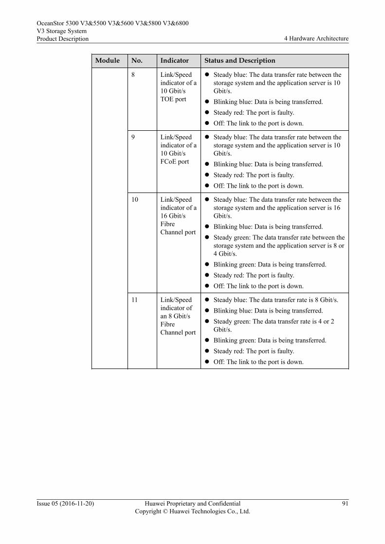
Module No. Indicator Status and Description
8 Link/Speedindicator of a10 Gbit/sTOE port
l Steady blue: The data transfer rate between thestorage system and the application server is 10Gbit/s.
l Blinking blue: Data is being transferred.l Steady red: The port is faulty.l Off: The link to the port is down.
9 Link/Speedindicator of a10 Gbit/sFCoE port
l Steady blue: The data transfer rate between thestorage system and the application server is 10Gbit/s.
l Blinking blue: Data is being transferred.l Steady red: The port is faulty.l Off: The link to the port is down.
10 Link/Speedindicator of a16 Gbit/sFibreChannel port
l Steady blue: The data transfer rate between thestorage system and the application server is 16Gbit/s.
l Blinking blue: Data is being transferred.l Steady green: The data transfer rate between the
storage system and the application server is 8 or4 Gbit/s.
l Blinking green: Data is being transferred.l Steady red: The port is faulty.l Off: The link to the port is down.
11 Link/Speedindicator ofan 8 Gbit/sFibreChannel port
l Steady blue: The data transfer rate is 8 Gbit/s.l Blinking blue: Data is being transferred.l Steady green: The data transfer rate is 4 or 2
Gbit/s.l Blinking green: Data is being transferred.l Steady red: The port is faulty.l Off: The link to the port is down.
OceanStor 5300 V3&5500 V3&5600 V3&5800 V3&6800V3 Storage SystemProduct Description 4 Hardware Architecture
Issue 05 (2016-11-20) Huawei Proprietary and ConfidentialCopyright © Huawei Technologies Co., Ltd.
91
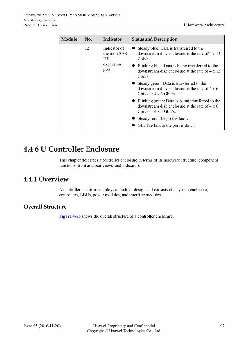
Module No. Indicator Status and Description
12 Indicator ofthe mini SASHDexpansionport
l Steady blue: Data is transferred to thedownstream disk enclosure at the rate of 4 x 12Gbit/s.
l Blinking blue: Data is being transferred to thedownstream disk enclosure at the rate of 4 x 12Gbit/s.
l Steady green: Data is transferred to thedownstream disk enclosure at the rate of 4 x 6Gbit/s or 4 x 3 Gbit/s.
l Blinking green: Data is being transferred to thedownstream disk enclosure at the rate of 4 x 6Gbit/s or 4 x 3 Gbit/s.
l Steady red: The port is faulty.l Off: The link to the port is down.
4.4 6 U Controller EnclosureThis chapter describes a controller enclosure in terms of its hardware structure, componentfunctions, front and rear views, and indicators.
4.4.1 OverviewA controller enclosure employs a modular design and consists of a system enclosure,controllers, BBUs, power modules, and interface modules.
Overall StructureFigure 4-55 shows the overall structure of a controller enclosure.
OceanStor 5300 V3&5500 V3&5600 V3&5800 V3&6800V3 Storage SystemProduct Description 4 Hardware Architecture
Issue 05 (2016-11-20) Huawei Proprietary and ConfidentialCopyright © Huawei Technologies Co., Ltd.
92
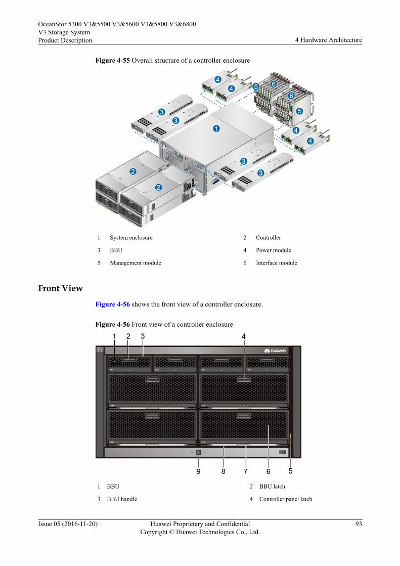
Figure 4-55 Overall structure of a controller enclosure
1 System enclosure 2 Controller
3 BBU 4 Power module
5 Management module 6 Interface module
Front View
Figure 4-56 shows the front view of a controller enclosure.
Figure 4-56 Front view of a controller enclosure
1 BBU 2 BBU latch
3 BBU handle 4 Controller panel latch
OceanStor 5300 V3&5500 V3&5600 V3&5800 V3&6800V3 Storage SystemProduct Description 4 Hardware Architecture
Issue 05 (2016-11-20) Huawei Proprietary and ConfidentialCopyright © Huawei Technologies Co., Ltd.
93
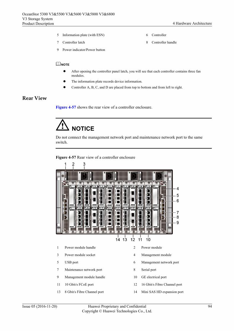
5 Information plate (with ESN) 6 Controller
7 Controller latch 8 Controller handle
9 Power indicator/Power button
NOTE
l After opening the controller panel latch, you will see that each controller contains three fanmodules.
l The information plate records device information.
l Controller A, B, C, and D are placed from top to bottom and from left to right.
Rear View
Figure 4-57 shows the rear view of a controller enclosure.
NOTICEDo not connect the management network port and maintenance network port to the sameswitch.
Figure 4-57 Rear view of a controller enclosure
1 Power module handle 2 Power module
3 Power module socket 4 Management module
5 USB port 6 Management network port
7 Maintenance network port 8 Serial port
9 Management module handle 10 GE electrical port
11 10 Gbit/s FCoE port 12 16 Gbit/s Fibre Channel port
13 8 Gbit/s Fibre Channel port 14 Mini SAS HD expansion port
OceanStor 5300 V3&5500 V3&5600 V3&5800 V3&6800V3 Storage SystemProduct Description 4 Hardware Architecture
Issue 05 (2016-11-20) Huawei Proprietary and ConfidentialCopyright © Huawei Technologies Co., Ltd.
94
The slots for interface modules of a 6 U controller enclosure are L0, L1, L2, L3, L4, L5, R5,R4, R3, R2, R1, and R0 from left to right. From the top to bottom, the slots are IOM0 andIOM1.
l R5IOM0 and R0IOM0 are slots for interface modules of controller A.
l L0IOM0 and L5IOM0 are slots for interface modules of controller B.
l R5IOM1 and R0IOM1 are slots for interface modules of controller C.
l L0IOM1 and L5IOM1 are slots for interface modules of controller D.
NOTEA controller enclosure provides the following interface modules. You can configure them based onservice needs.
l Slots L0IOM0, R0IOM0, L0IOM1 and R0IOM1 are slots for back-end interface modules and onlysupport 12 Gbit/s SAS expansion modules.
l Slots L4IOM0, L5IOM0, R4IOM0, R5IOM0, L4IOM1, L5IOM1, R4IOM1 and R5IOM1 are slotsfor front-end interface modules and do not support 12 Gbit/s SAS expansion modules.
l When the storage system requires IP Scale-out, SmartIO interface modules must be installed inL3IOM0, R3IOM0, L3IOM1 and R3IOM1 slots for the IP Scale-out.
l Insert interface modules of the same type into a slot of controller A and the corresponding slot ofcontroller B. Insert interface modules of the same type into a slot of controller C and thecorresponding slot of controller D.
For example, if you insert a 10 Gbit/s TOE interface module into slot R2IOM0 of controller A, youmust insert a 10 Gbit/s TOE interface module into slot L2IOM0 on controller B.
l Management module (mandatory): used for management and maintenance
l 12 Gbit/s SAS expansion module (mandatory): used for connecting disk enclosures
l Interface modules (optional but at least one type required): used for connecting application servers
l Management network ports 1 and 2 have not been enabled, and will be enabled in multi-controllerinterconnection scenarios.
l When the maintenance network port is used for management and maintenance, the maintenancenetwork port can only be used by Huawei technical support for emergency maintenance and cannotbe connected to the same network with the management network port. Otherwise, a networkloopback may occur, causing a network storm. The initial value for the IP address of themaintenance network port is 172.31.128.101 or 172.31.128.102. The default subnet mask is255.255.0.0. You are advised to only connect the management network port to the network.
4.4.2 Component DescriptionThis section provides the illustration and description of each component of the storagesystem.
4.4.2.1 System Enclosure
The system enclosure integrates a midplane in order to provide reliable connections forinterface modules and to distribute power and signals to inner modules.
Appearance
Figure 4-58 shows the appearance of a system enclosure.
OceanStor 5300 V3&5500 V3&5600 V3&5800 V3&6800V3 Storage SystemProduct Description 4 Hardware Architecture
Issue 05 (2016-11-20) Huawei Proprietary and ConfidentialCopyright © Huawei Technologies Co., Ltd.
95
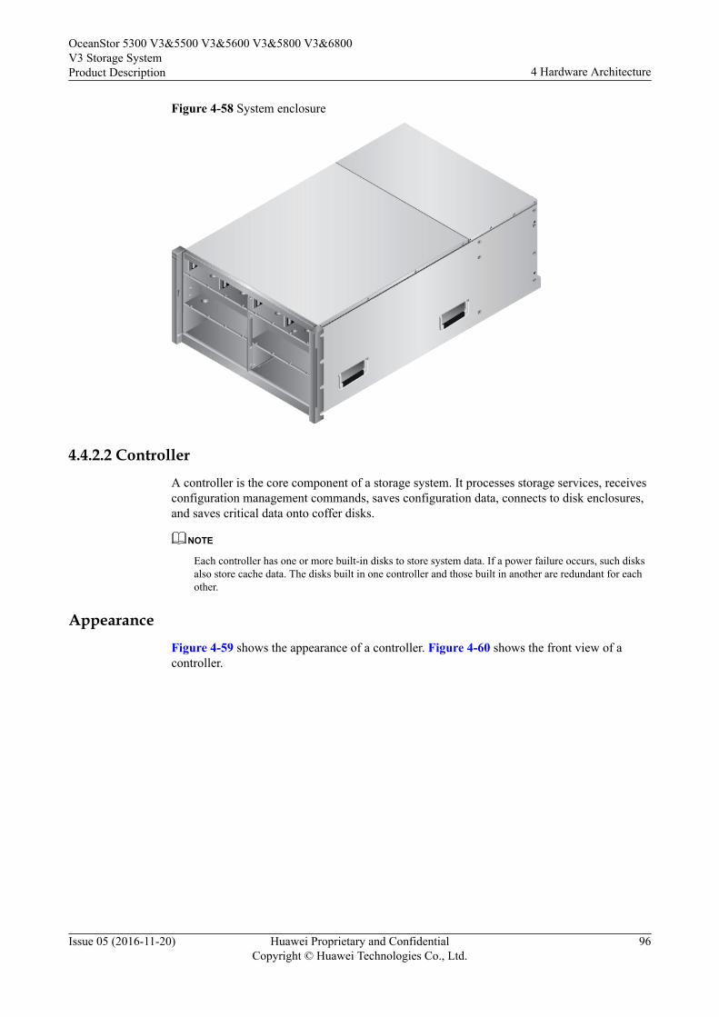
Figure 4-58 System enclosure
4.4.2.2 ControllerA controller is the core component of a storage system. It processes storage services, receivesconfiguration management commands, saves configuration data, connects to disk enclosures,and saves critical data onto coffer disks.
NOTE
Each controller has one or more built-in disks to store system data. If a power failure occurs, such disksalso store cache data. The disks built in one controller and those built in another are redundant for eachother.
AppearanceFigure 4-59 shows the appearance of a controller. Figure 4-60 shows the front view of acontroller.
OceanStor 5300 V3&5500 V3&5600 V3&5800 V3&6800V3 Storage SystemProduct Description 4 Hardware Architecture
Issue 05 (2016-11-20) Huawei Proprietary and ConfidentialCopyright © Huawei Technologies Co., Ltd.
96
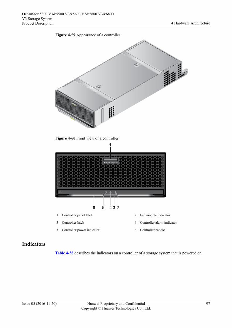
Figure 4-59 Appearance of a controller
Figure 4-60 Front view of a controller
1 Controller panel latch 2 Fan module indicator
3 Controller latch 4 Controller alarm indicator
5 Controller power indicator 6 Controller handle
IndicatorsTable 4-38 describes the indicators on a controller of a storage system that is powered on.
OceanStor 5300 V3&5500 V3&5600 V3&5800 V3&6800V3 Storage SystemProduct Description 4 Hardware Architecture
Issue 05 (2016-11-20) Huawei Proprietary and ConfidentialCopyright © Huawei Technologies Co., Ltd.
97
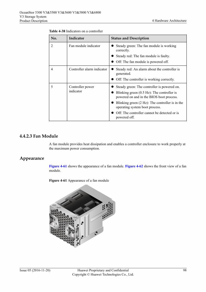
Table 4-38 Indicators on a controller
No. Indicator Status and Description
2 Fan module indicator l Steady green: The fan module is workingcorrectly.
l Steady red: The fan module is faulty.l Off: The fan module is powered off.
4 Controller alarm indicator l Steady red: An alarm about the controller isgenerated.
l Off: The controller is working correctly.
5 Controller powerindicator
l Steady green: The controller is powered on.l Blinking green (0.5 Hz): The controller is
powered on and in the BIOS boot process.l Blinking green (2 Hz): The controller is in the
operating system boot process.l Off: The controller cannot be detected or is
powered off.
4.4.2.3 Fan ModuleA fan module provides heat dissipation and enables a controller enclosure to work properly atthe maximum power consumption.
AppearanceFigure 4-61 shows the appearance of a fan module. Figure 4-62 shows the front view of a fanmodule.
Figure 4-61 Appearance of a fan module
OceanStor 5300 V3&5500 V3&5600 V3&5800 V3&6800V3 Storage SystemProduct Description 4 Hardware Architecture
Issue 05 (2016-11-20) Huawei Proprietary and ConfidentialCopyright © Huawei Technologies Co., Ltd.
98
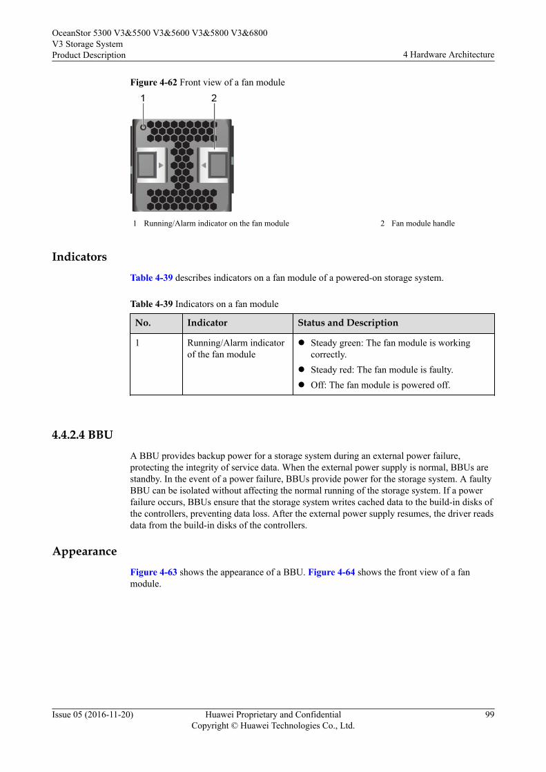
Figure 4-62 Front view of a fan module
1 Running/Alarm indicator on the fan module 2 Fan module handle
IndicatorsTable 4-39 describes indicators on a fan module of a powered-on storage system.
Table 4-39 Indicators on a fan module
No. Indicator Status and Description
1 Running/Alarm indicatorof the fan module
l Steady green: The fan module is workingcorrectly.
l Steady red: The fan module is faulty.l Off: The fan module is powered off.
4.4.2.4 BBUA BBU provides backup power for a storage system during an external power failure,protecting the integrity of service data. When the external power supply is normal, BBUs arestandby. In the event of a power failure, BBUs provide power for the storage system. A faultyBBU can be isolated without affecting the normal running of the storage system. If a powerfailure occurs, BBUs ensure that the storage system writes cached data to the build-in disks ofthe controllers, preventing data loss. After the external power supply resumes, the driver readsdata from the build-in disks of the controllers.
AppearanceFigure 4-63 shows the appearance of a BBU. Figure 4-64 shows the front view of a fanmodule.
OceanStor 5300 V3&5500 V3&5600 V3&5800 V3&6800V3 Storage SystemProduct Description 4 Hardware Architecture
Issue 05 (2016-11-20) Huawei Proprietary and ConfidentialCopyright © Huawei Technologies Co., Ltd.
99
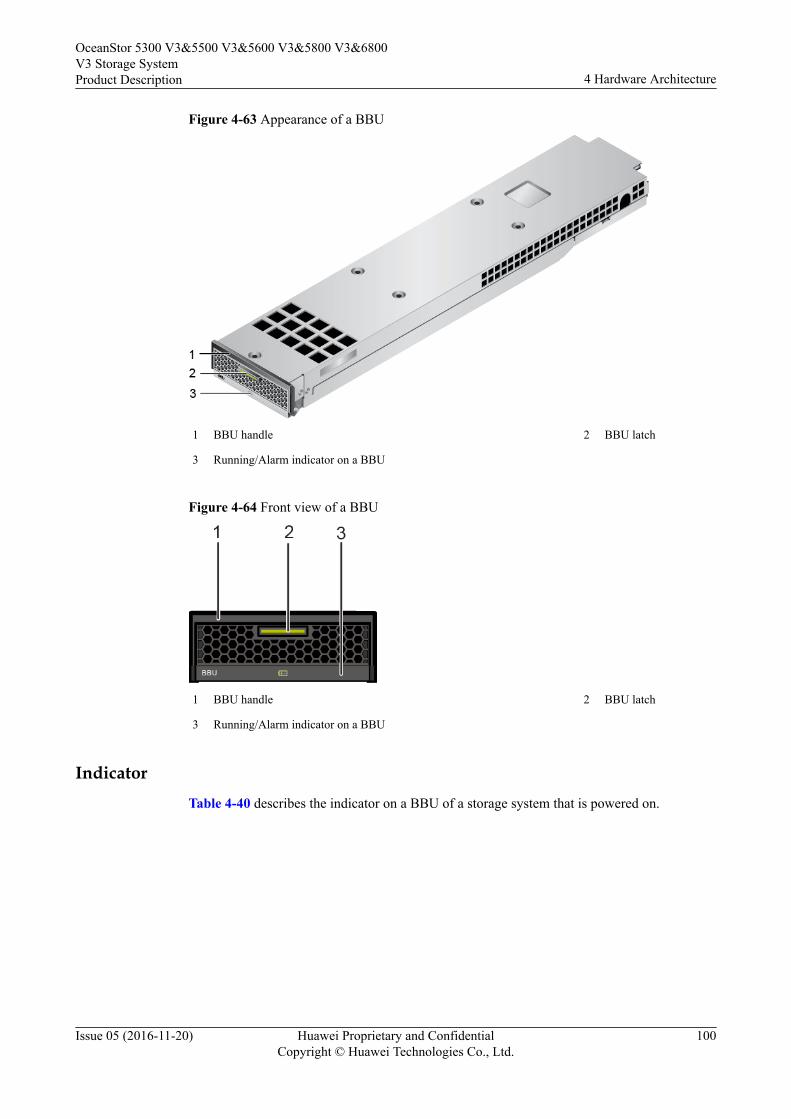
Figure 4-63 Appearance of a BBU
1 BBU handle 2 BBU latch
3 Running/Alarm indicator on a BBU
Figure 4-64 Front view of a BBU
1 BBU handle 2 BBU latch
3 Running/Alarm indicator on a BBU
IndicatorTable 4-40 describes the indicator on a BBU of a storage system that is powered on.
OceanStor 5300 V3&5500 V3&5600 V3&5800 V3&6800V3 Storage SystemProduct Description 4 Hardware Architecture
Issue 05 (2016-11-20) Huawei Proprietary and ConfidentialCopyright © Huawei Technologies Co., Ltd.
100
Table 4-40 Indicator on a BBU
No. Indicator Status and Description
3 Running/Alarm indicatoron a BBU
l Steady green: The BBU is fully charged.l Blinking green (1 Hz): The BBU is being
charged.l Blinking green (4 Hz): The BBU is being
discharged.l Steady red: The BBU is faulty.l Off: The interface module is powered off or
hot swappable.
4.4.2.5 16 Gbit/s Fibre Channel Interface ModuleInterface modules connect storage devices to application servers.
FunctionA 16 Gbit/s Fibre Channel interface module provides two 16 Gbit/s Fibre Channel ports.These ports are service ports used to connect a storage system to application servers andreceive data read/write requests from application servers. If the data transfer rate of anapplication server connected to such a port is lower than the port rate and the port mode is setto autonegotiation, the port automatically adjusts its rate to ensure the connectivity of the datatransfer channel and the consistency of the data transfer rate. If the port rate is manually setbut inconsistent with the data transfer rate of the connected application server, the connectionis interrupted.
PortsFigure 4-65 shows the appearance of a 16 Gbit/s Fibre Channel interface module.
OceanStor 5300 V3&5500 V3&5600 V3&5800 V3&6800V3 Storage SystemProduct Description 4 Hardware Architecture
Issue 05 (2016-11-20) Huawei Proprietary and ConfidentialCopyright © Huawei Technologies Co., Ltd.
101
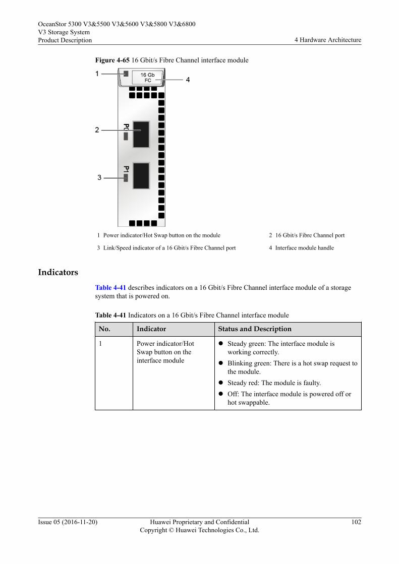
Figure 4-65 16 Gbit/s Fibre Channel interface module
1 Power indicator/Hot Swap button on the module 2 16 Gbit/s Fibre Channel port
3 Link/Speed indicator of a 16 Gbit/s Fibre Channel port 4 Interface module handle
IndicatorsTable 4-41 describes indicators on a 16 Gbit/s Fibre Channel interface module of a storagesystem that is powered on.
Table 4-41 Indicators on a 16 Gbit/s Fibre Channel interface module
No. Indicator Status and Description
1 Power indicator/HotSwap button on theinterface module
l Steady green: The interface module isworking correctly.
l Blinking green: There is a hot swap request tothe module.
l Steady red: The module is faulty.l Off: The interface module is powered off or
hot swappable.
OceanStor 5300 V3&5500 V3&5600 V3&5800 V3&6800V3 Storage SystemProduct Description 4 Hardware Architecture
Issue 05 (2016-11-20) Huawei Proprietary and ConfidentialCopyright © Huawei Technologies Co., Ltd.
102
No. Indicator Status and Description
3 Link/Speed indicator ofthe 16 Gbit/s FibreChannel port
l Steady blue: The data transfer rate betweenthe storage system and the application serveris 16 Gbit/s.
l Blinking blue: Data is being transferred.l Steady green: The data transfer rate between
the storage system and the application serveris 8 Gbit/s or 4 Gbit/s.
l Blinking green: Data is being transferred.l Steady red: The port is faulty.l Off: The link to the port is down.
4.4.2.6 8 Gbit/s Fibre Channel Interface ModuleInterface modules connect storage devices to application servers.
FunctionAn 8 Gbit/s Fibre Channel interface module provides four 8 Gbit/s Fibre Channel ports. Theseports are service ports used to connect a storage system to application servers and receive dataread/write requests from application servers. If the data transfer rate of an application serverconnected to such a port is lower than the port rate and the port mode is set to autonegotiation,the port automatically adjusts its rate to ensure the connectivity of the data transfer channeland the consistency of the data transfer rate. If the port rate is manually set but inconsistentwith the data transfer rate of the connected application server, the connection is interrupted.
PortsFigure 4-66 shows the appearance of an 8 Gbit/s Fibre Channel interface module.
OceanStor 5300 V3&5500 V3&5600 V3&5800 V3&6800V3 Storage SystemProduct Description 4 Hardware Architecture
Issue 05 (2016-11-20) Huawei Proprietary and ConfidentialCopyright © Huawei Technologies Co., Ltd.
103
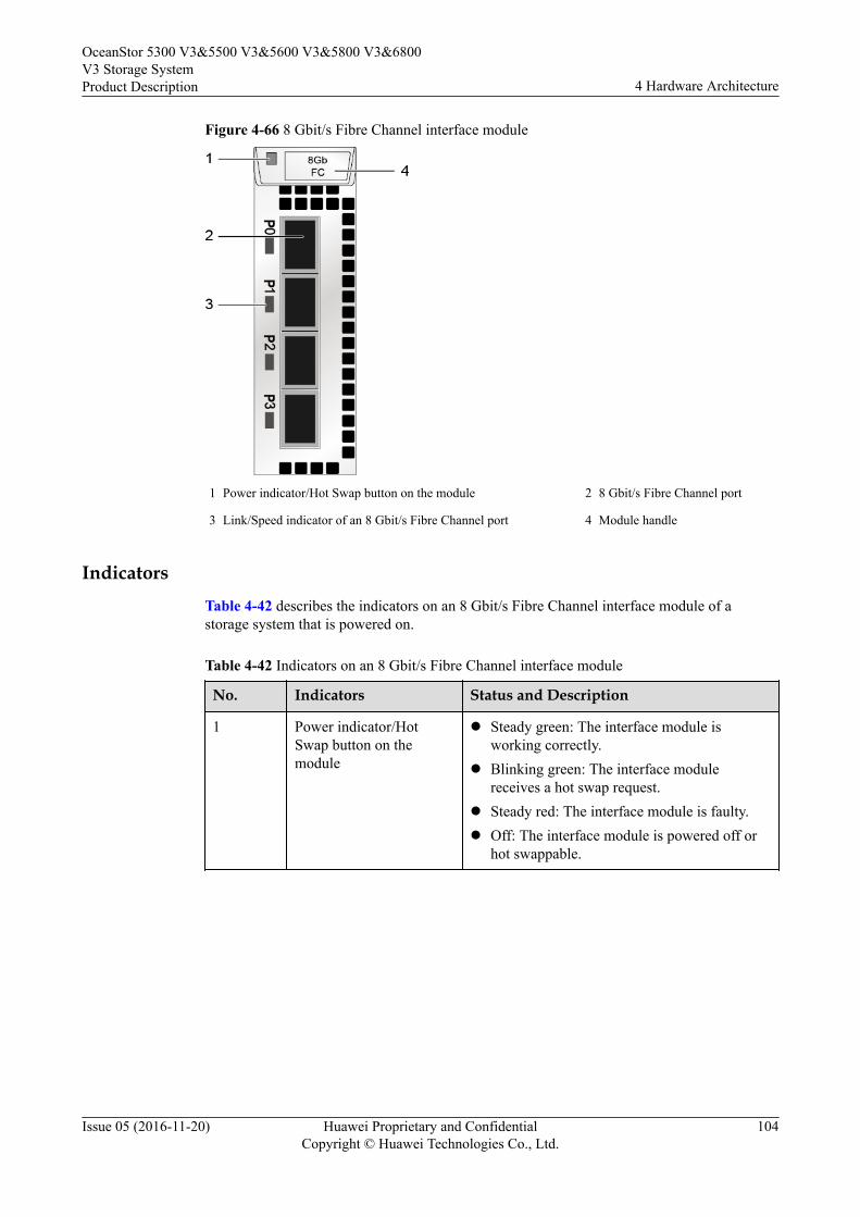
Figure 4-66 8 Gbit/s Fibre Channel interface module
1 Power indicator/Hot Swap button on the module 2 8 Gbit/s Fibre Channel port
3 Link/Speed indicator of an 8 Gbit/s Fibre Channel port 4 Module handle
IndicatorsTable 4-42 describes the indicators on an 8 Gbit/s Fibre Channel interface module of astorage system that is powered on.
Table 4-42 Indicators on an 8 Gbit/s Fibre Channel interface module
No. Indicators Status and Description
1 Power indicator/HotSwap button on themodule
l Steady green: The interface module isworking correctly.
l Blinking green: The interface modulereceives a hot swap request.
l Steady red: The interface module is faulty.l Off: The interface module is powered off or
hot swappable.
OceanStor 5300 V3&5500 V3&5600 V3&5800 V3&6800V3 Storage SystemProduct Description 4 Hardware Architecture
Issue 05 (2016-11-20) Huawei Proprietary and ConfidentialCopyright © Huawei Technologies Co., Ltd.
104
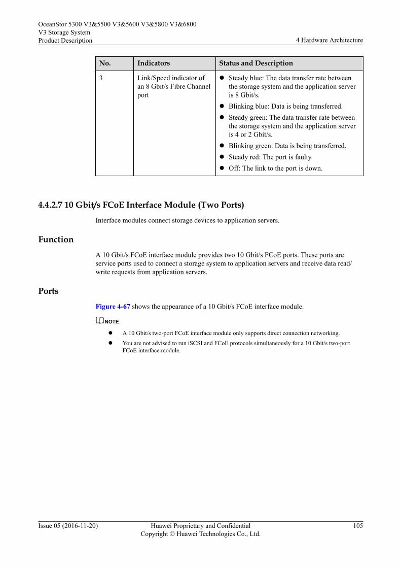
No. Indicators Status and Description
3 Link/Speed indicator ofan 8 Gbit/s Fibre Channelport
l Steady blue: The data transfer rate betweenthe storage system and the application serveris 8 Gbit/s.
l Blinking blue: Data is being transferred.l Steady green: The data transfer rate between
the storage system and the application serveris 4 or 2 Gbit/s.
l Blinking green: Data is being transferred.l Steady red: The port is faulty.l Off: The link to the port is down.
4.4.2.7 10 Gbit/s FCoE Interface Module (Two Ports)Interface modules connect storage devices to application servers.
FunctionA 10 Gbit/s FCoE interface module provides two 10 Gbit/s FCoE ports. These ports areservice ports used to connect a storage system to application servers and receive data read/write requests from application servers.
PortsFigure 4-67 shows the appearance of a 10 Gbit/s FCoE interface module.
NOTE
l A 10 Gbit/s two-port FCoE interface module only supports direct connection networking.
l You are not advised to run iSCSI and FCoE protocols simultaneously for a 10 Gbit/s two-portFCoE interface module.
OceanStor 5300 V3&5500 V3&5600 V3&5800 V3&6800V3 Storage SystemProduct Description 4 Hardware Architecture
Issue 05 (2016-11-20) Huawei Proprietary and ConfidentialCopyright © Huawei Technologies Co., Ltd.
105
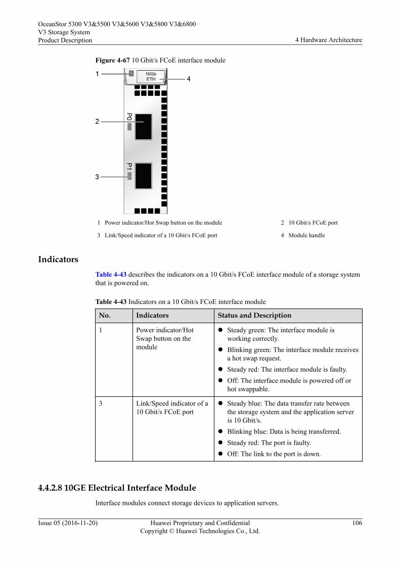
Figure 4-67 10 Gbit/s FCoE interface module
1 Power indicator/Hot Swap button on the module 2 10 Gbit/s FCoE port
3 Link/Speed indicator of a 10 Gbit/s FCoE port 4 Module handle
IndicatorsTable 4-43 describes the indicators on a 10 Gbit/s FCoE interface module of a storage systemthat is powered on.
Table 4-43 Indicators on a 10 Gbit/s FCoE interface module
No. Indicators Status and Description
1 Power indicator/HotSwap button on themodule
l Steady green: The interface module isworking correctly.
l Blinking green: The interface module receivesa hot swap request.
l Steady red: The interface module is faulty.l Off: The interface module is powered off or
hot swappable.
3 Link/Speed indicator of a10 Gbit/s FCoE port
l Steady blue: The data transfer rate betweenthe storage system and the application serveris 10 Gbit/s.
l Blinking blue: Data is being transferred.l Steady red: The port is faulty.l Off: The link to the port is down.
4.4.2.8 10GE Electrical Interface ModuleInterface modules connect storage devices to application servers.
OceanStor 5300 V3&5500 V3&5600 V3&5800 V3&6800V3 Storage SystemProduct Description 4 Hardware Architecture
Issue 05 (2016-11-20) Huawei Proprietary and ConfidentialCopyright © Huawei Technologies Co., Ltd.
106

FunctionA 10GE electrical interface module has four 10 Gbit/s electrical ports. These ports are theservice ports used to connect the storage system to application servers and to receive dataread/write requests from application servers.
PortsFigure 4-68 shows the appearance of a 10GE electrical interface module.
Figure 4-68 10GE electrical interface module
1 Power indicator/Hot Swap button on the interface module 2 10GE electrical port
3 Link/Active indicator of the 10GE electrical port 4 Speed indicator of the 10GE electrical port
5 Interface module handle
NOTE
Adaptive connections cannot be implemented between 10GE electrical ports and GE electrical ports ofthe storage system.
IndicatorsTable 4-44 describes indicators on a 10GE electrical interface module of a powered-onstorage system.
OceanStor 5300 V3&5500 V3&5600 V3&5800 V3&6800V3 Storage SystemProduct Description 4 Hardware Architecture
Issue 05 (2016-11-20) Huawei Proprietary and ConfidentialCopyright © Huawei Technologies Co., Ltd.
107
Table 4-44 Indicators on a 10GE electrical interface module
No. Indicator Status and Description
1 Power indicator/HotSwap button on theinterface module
l Steady green: The interface module isworking correctly.
l Blinking green: There is a hot swap request tothe module.
l Steady red: The module is faulty.l Off: The module is powered off or hot
swappable.
3 Link/Active indicator ofthe 10GE electrical port
l Steady green: The link to the server is normal.l Blinking green: Data is being transferred.l Off: The link to the application server is down
or no link exists.
4 Speed indicator of the10GE electrical port
l Steady orange: The data transfer rate of themanagement network port is 10 Gbit/s.
l Off: The data transfer rate of the managementnetwork port is less than 10 Gbit/s.
4.4.2.9 GE Electrical Interface ModuleInterface modules connect storage devices to application servers.
FunctionA GE electrical interface module has four 1 Gbit/s electrical ports. These ports are the serviceports used to connect the storage system to application servers and to receive data read/writerequests from application servers.
PortsFigure 4-69 shows the appearance of a GE electrical interface module.
OceanStor 5300 V3&5500 V3&5600 V3&5800 V3&6800V3 Storage SystemProduct Description 4 Hardware Architecture
Issue 05 (2016-11-20) Huawei Proprietary and ConfidentialCopyright © Huawei Technologies Co., Ltd.
108
Figure 4-69 GE electrical interface module
1 Power indicator/Hot Swap button on the interface module 2 GE electrical port
3 Link/Active indicator of the GE electrical port 4 Speed indicator of the GE electrical port
5 Interface module handle
Indicators
Table 4-45 describes indicators on a GE electrical interface module of a powered-on storagesystem.
Table 4-45 Indicators on a GE electrical interface module
No. Indicator Status and Description
1 Power indicator/HotSwap button on theinterface module
l Steady green: The interface module isworking correctly.
l Blinking green: There is a hot swap request tothe module.
l Steady red: The module is faulty.l Off: The interface module is powered off or
hot swappable.
3 Link/Active indicator ofthe GE electrical port
l Steady green: The link to the server is normal.l Blinking green: Data is being transferred.l Off: The link to the application server is down
or no link exists.
4 Speed indicator of the GEelectrical port
l Steady orange: The data transfer rate betweenthe storage system and the application serveris 1 Gbit/s.
l Off: The data transfer rate between thestorage system and the application server isless than 1 Gbit/s.
OceanStor 5300 V3&5500 V3&5600 V3&5800 V3&6800V3 Storage SystemProduct Description 4 Hardware Architecture
Issue 05 (2016-11-20) Huawei Proprietary and ConfidentialCopyright © Huawei Technologies Co., Ltd.
109
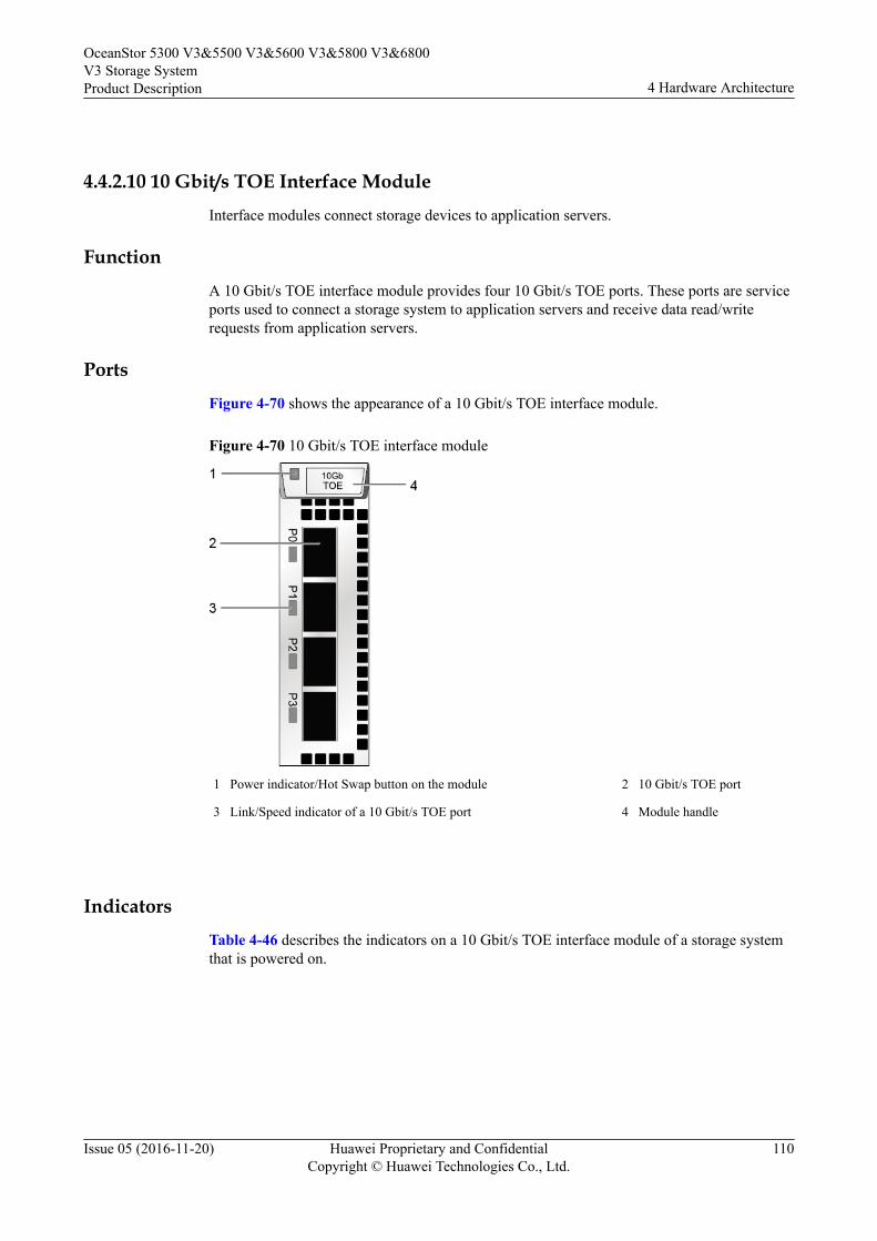
4.4.2.10 10 Gbit/s TOE Interface ModuleInterface modules connect storage devices to application servers.
FunctionA 10 Gbit/s TOE interface module provides four 10 Gbit/s TOE ports. These ports are serviceports used to connect a storage system to application servers and receive data read/writerequests from application servers.
PortsFigure 4-70 shows the appearance of a 10 Gbit/s TOE interface module.
Figure 4-70 10 Gbit/s TOE interface module
1 Power indicator/Hot Swap button on the module 2 10 Gbit/s TOE port
3 Link/Speed indicator of a 10 Gbit/s TOE port 4 Module handle
IndicatorsTable 4-46 describes the indicators on a 10 Gbit/s TOE interface module of a storage systemthat is powered on.
OceanStor 5300 V3&5500 V3&5600 V3&5800 V3&6800V3 Storage SystemProduct Description 4 Hardware Architecture
Issue 05 (2016-11-20) Huawei Proprietary and ConfidentialCopyright © Huawei Technologies Co., Ltd.
110
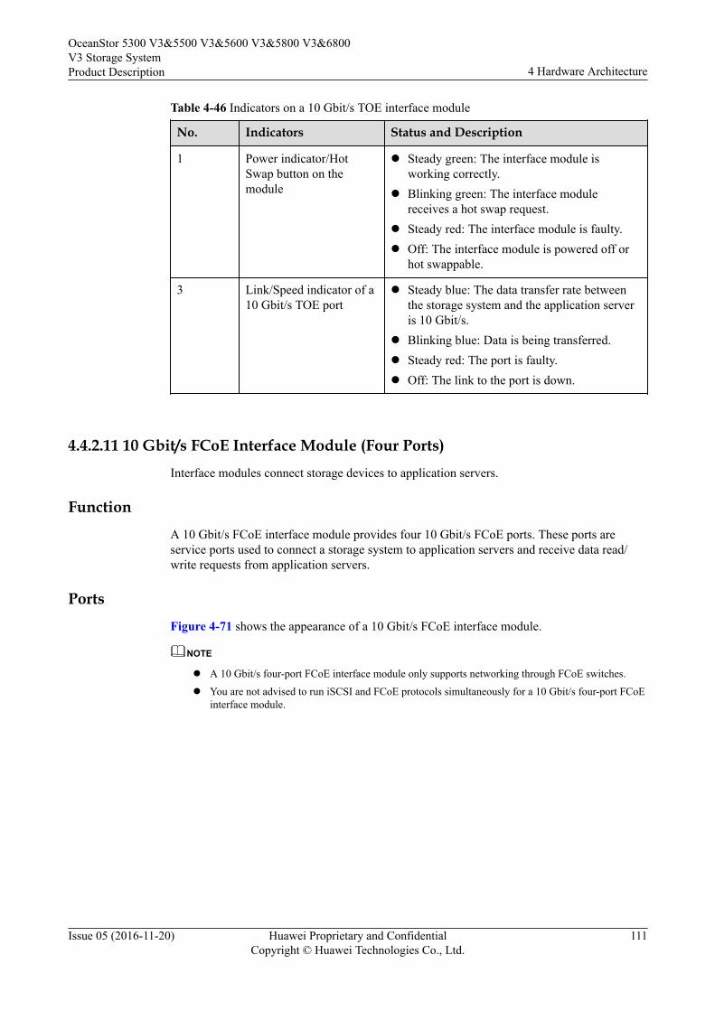
Table 4-46 Indicators on a 10 Gbit/s TOE interface module
No. Indicators Status and Description
1 Power indicator/HotSwap button on themodule
l Steady green: The interface module isworking correctly.
l Blinking green: The interface modulereceives a hot swap request.
l Steady red: The interface module is faulty.l Off: The interface module is powered off or
hot swappable.
3 Link/Speed indicator of a10 Gbit/s TOE port
l Steady blue: The data transfer rate betweenthe storage system and the application serveris 10 Gbit/s.
l Blinking blue: Data is being transferred.l Steady red: The port is faulty.l Off: The link to the port is down.
4.4.2.11 10 Gbit/s FCoE Interface Module (Four Ports)Interface modules connect storage devices to application servers.
FunctionA 10 Gbit/s FCoE interface module provides four 10 Gbit/s FCoE ports. These ports areservice ports used to connect a storage system to application servers and receive data read/write requests from application servers.
PortsFigure 4-71 shows the appearance of a 10 Gbit/s FCoE interface module.
NOTE
l A 10 Gbit/s four-port FCoE interface module only supports networking through FCoE switches.
l You are not advised to run iSCSI and FCoE protocols simultaneously for a 10 Gbit/s four-port FCoEinterface module.
OceanStor 5300 V3&5500 V3&5600 V3&5800 V3&6800V3 Storage SystemProduct Description 4 Hardware Architecture
Issue 05 (2016-11-20) Huawei Proprietary and ConfidentialCopyright © Huawei Technologies Co., Ltd.
111

Figure 4-71 10 Gbit/s FCoE interface module
1 Power indicator/Hot Swap button on the module 2 10 Gbit/s FCoE port
3 Link/Speed indicator of a 10 Gbit/s FCoE port 4 Module handle
Indicators
Table 4-47 describes the indicators on a 10 Gbit/s FCoE interface module of a storage systemthat is powered on.
Table 4-47 Indicators on a 10 Gbit/s FCoE interface module
No. Indicators Status and Description
1 Power indicator/HotSwap button on themodule
l Steady green: The interface module isworking correctly.
l Blinking green: The interface module receivesa hot swap request.
l Steady red: The interface module is faulty.l Off: The interface module is powered off or
hot swappable.
3 Link/Speed indicator of a10 Gbit/s FCoE port
l Steady blue: The data transfer rate betweenthe storage system and the application serveris 10 Gbit/s.
l Blinking blue: Data is being transferred.l Steady red: The port is faulty.l Off: The link to the port is down.
OceanStor 5300 V3&5500 V3&5600 V3&5800 V3&6800V3 Storage SystemProduct Description 4 Hardware Architecture
Issue 05 (2016-11-20) Huawei Proprietary and ConfidentialCopyright © Huawei Technologies Co., Ltd.
112
4.4.2.12 56 Gbit/s IB Interface ModuleInterface modules connect storage devices to application servers.
FunctionA 56 Gbit/s IB interface module provides two 4 x 14 Gbit/s IB ports. Both are the serviceports used to connect to application servers and to receive data read/write requests fromapplication servers.
InterfaceFigure 4-72 shows the appearance of a 56 Gbit/s IB interface module.
Figure 4-72 56 Gbit/s IB interface module
1 Power indicator/Hot Swap button of the module 2 56 Gbit/s IB port Link indicator
3 56 Gbit/s IB port Active indicator 4 56 Gbit/s IB port
5 Module handle
IndicatorsTable 4-48 describes the states of indicators and their meanings on a 56 Gbit/s IB interfacemodule after the storage device is powered on.
OceanStor 5300 V3&5500 V3&5600 V3&5800 V3&6800V3 Storage SystemProduct Description 4 Hardware Architecture
Issue 05 (2016-11-20) Huawei Proprietary and ConfidentialCopyright © Huawei Technologies Co., Ltd.
113

Table 4-48 Indicator status description for a 56 Gbit/s IB interface module
No. Indicator Status Description
1 Power indicator/HotSwap button of themodule
l Steady green: The interface module isworking correctly.
l Blinking green: There is a hot swap request tothe module.
l Steady red: The module is faulty.l Off: The interface module is powered off or
hot swappable.
2 56 Gbit/s IB port Linkindicator
l Steady green: The port is connected properly.l Off: The port link is down.
3 56 Gbit/s IB port Activeindicator
l Steady orange: Data is being transmitted.l Off: No data is being transmitted.
4.4.2.13 SmartIO Interface ModuleInterface modules are mainly used to connect storage devices to application servers.
FunctionA SmartIO interface module provides 16 Gbit/s, 8 Gbit/s and 10 Gbit/s optical transceiver.They are the service ports used to connect to application servers and to receive data read/writerequests from application servers.
InterfaceFigure 4-73 shows the components of a SmartIO interface module.
OceanStor 5300 V3&5500 V3&5600 V3&5800 V3&6800V3 Storage SystemProduct Description 4 Hardware Architecture
Issue 05 (2016-11-20) Huawei Proprietary and ConfidentialCopyright © Huawei Technologies Co., Ltd.
114

Figure 4-73 SmartIO interface module
1 Module Power/Hot Swap indicator 2 SmartIO port
3 Port Link/Active/Mode indicator 4 Port mode silkscreen
5 Module handle
IndicatorsTable 4-49 describes the states of indicators and their meanings on a SmartIO interfacemodule after the storage device is powered on.
Table 4-49 Indicator status description for a SmartIO interface module
No. Indicator Status Description
1 Module Power/Hot Swapbutton
l Steady green: The interface module isrunning properly.
l Blinking green: The interface modulereceives a hot swap request.
l Steady red: The interface module is faulty.l Off: The interface module is not powered on
or can be hot-swapped.
OceanStor 5300 V3&5500 V3&5600 V3&5800 V3&6800V3 Storage SystemProduct Description 4 Hardware Architecture
Issue 05 (2016-11-20) Huawei Proprietary and ConfidentialCopyright © Huawei Technologies Co., Ltd.
115
No. Indicator Status Description
3 Port Link/Active/Modeindicator
l Blinking blue slowly: The interface module isworking in FC mode, and the port link isdown.
l Blinking blue quickly: The interface moduleis working in FC mode, and data is beingtransmitted.
l Steady blue: The interface module is workingin FC mode, the port link is up, and no data isbeing transmitted.
l Blinking green slowly: The interface moduleis working in ETH mode, and the port link isdown.
l Blinking green quickly: The interface moduleis working in ETH mode, and data is beingtransmitted.
l Steady green: The interface module isworking in ETH mode, the port link is up, andno data is being transmitted.
l Steady red: The port is faulty.l Blinking red: The port is being located.l Off: The port is not powered on.
NOTE
l If the mode of the SmartIO port is set to FCoE/iSCSI or Cluster on the software interface, the portindicator is in ETH mode. The SmartIO port need to configure with 10 Gbit/s optical modules.
l If the mode of the SmartIO port is set to FC on the software interface, the port indicator is in FCmode. The SmartIO port need to configure with 8 Gbit/s or 16 Gbit/s optical modules.
l Connect a network only through FCoE switches when the SmartIO interface module is set to FCoE/iSCSI and the host uses the FCoE protocol. The SmartIO port need to configure with 10 Gbit/soptical modules.
4.4.2.14 Smart ACC Module (Applicable to V300R003C00/V300R003C10)
Smart ACC modules are mainly used to improve system performance.
Function
Smart ACC modules can concurrently provide functions such as fixed-length deduplication,fingerprint computing, and hardware acceleration for GZIP compression and decompression,reducing CPU load and promoting deduplication and compression performance.
Interface
Figure 4-74 shows the components of a Smart ACC module.
OceanStor 5300 V3&5500 V3&5600 V3&5800 V3&6800V3 Storage SystemProduct Description 4 Hardware Architecture
Issue 05 (2016-11-20) Huawei Proprietary and ConfidentialCopyright © Huawei Technologies Co., Ltd.
116
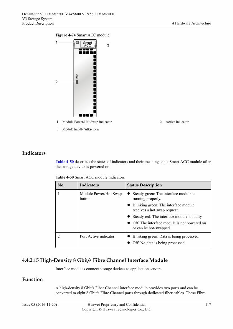
Figure 4-74 Smart ACC module
1 Module Power/Hot Swap indicator 2 Active indicator
3 Module handle/silkscreen
IndicatorsTable 4-50 describes the states of indicators and their meanings on a Smart ACC module afterthe storage device is powered on.
Table 4-50 Smart ACC module indicators
No. Indicators Status Description
1 Module Power/Hot Swapbutton
l Steady green: The interface module isrunning properly.
l Blinking green: The interface modulereceives a hot swap request.
l Steady red: The interface module is faulty.l Off: The interface module is not powered on
or can be hot-swapped.
2 Port Active indicator l Blinking green: Data is being processed.l Off: No data is being processed.
4.4.2.15 High-Density 8 Gbit/s Fibre Channel Interface ModuleInterface modules connect storage devices to application servers.
FunctionA high-density 8 Gbit/s Fiber Channel interface module provides two ports and can beconverted to eight 8 Gbit/s Fibre Channel ports through dedicated fiber cables. These Fibre
OceanStor 5300 V3&5500 V3&5600 V3&5800 V3&6800V3 Storage SystemProduct Description 4 Hardware Architecture
Issue 05 (2016-11-20) Huawei Proprietary and ConfidentialCopyright © Huawei Technologies Co., Ltd.
117
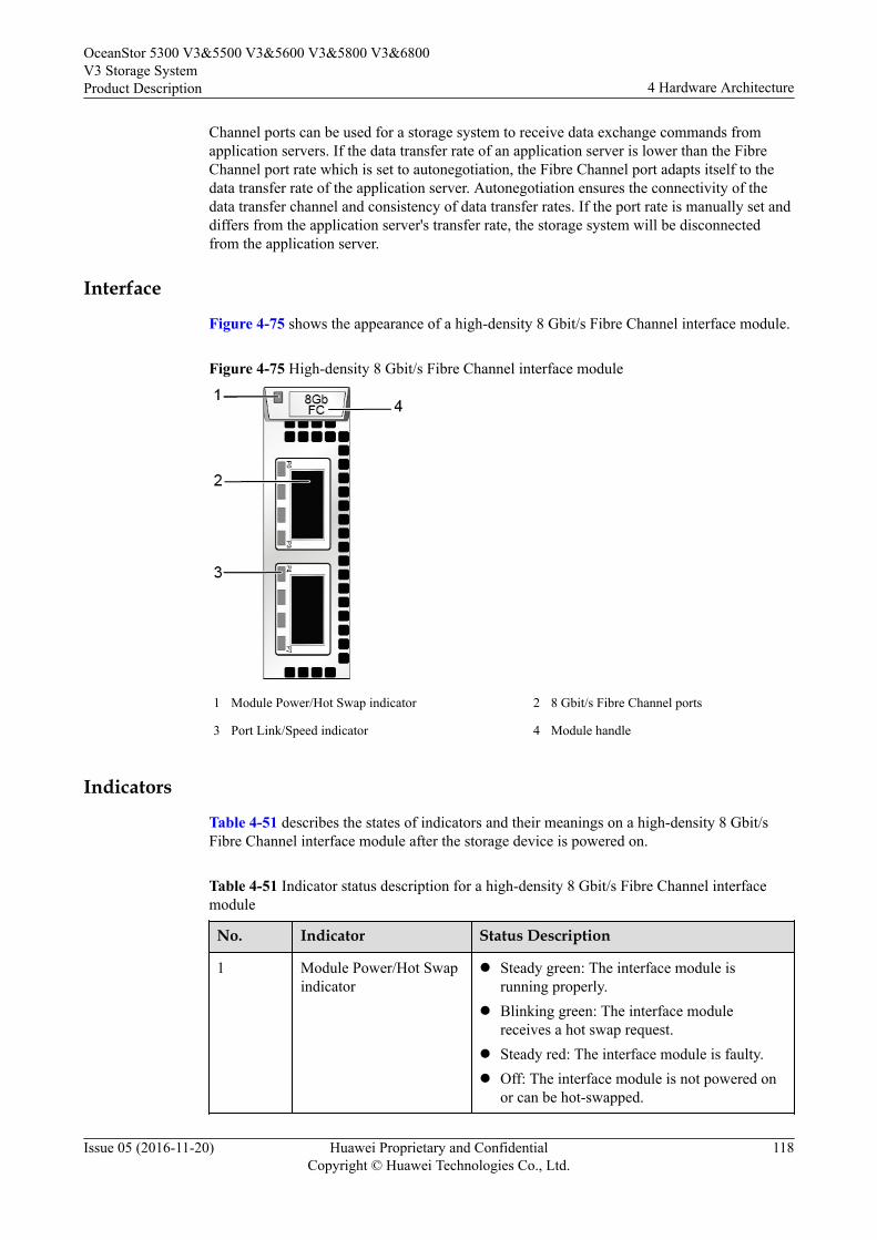
Channel ports can be used for a storage system to receive data exchange commands fromapplication servers. If the data transfer rate of an application server is lower than the FibreChannel port rate which is set to autonegotiation, the Fibre Channel port adapts itself to thedata transfer rate of the application server. Autonegotiation ensures the connectivity of thedata transfer channel and consistency of data transfer rates. If the port rate is manually set anddiffers from the application server's transfer rate, the storage system will be disconnectedfrom the application server.
Interface
Figure 4-75 shows the appearance of a high-density 8 Gbit/s Fibre Channel interface module.
Figure 4-75 High-density 8 Gbit/s Fibre Channel interface module
1 Module Power/Hot Swap indicator 2 8 Gbit/s Fibre Channel ports
3 Port Link/Speed indicator 4 Module handle
Indicators
Table 4-51 describes the states of indicators and their meanings on a high-density 8 Gbit/sFibre Channel interface module after the storage device is powered on.
Table 4-51 Indicator status description for a high-density 8 Gbit/s Fibre Channel interfacemodule
No. Indicator Status Description
1 Module Power/Hot Swapindicator
l Steady green: The interface module isrunning properly.
l Blinking green: The interface modulereceives a hot swap request.
l Steady red: The interface module is faulty.l Off: The interface module is not powered on
or can be hot-swapped.
OceanStor 5300 V3&5500 V3&5600 V3&5800 V3&6800V3 Storage SystemProduct Description 4 Hardware Architecture
Issue 05 (2016-11-20) Huawei Proprietary and ConfidentialCopyright © Huawei Technologies Co., Ltd.
118

No. Indicator Status Description
3 Link/Speed indicator ofthe 8 Gbit/s FibreChannel host port
l Steady blue: Data is being transmittedbetween the storage system and theapplication server at a rate of 8 Gbit/s.
l Blinking blue: Data is being transferred.l Steady green: Data is being transmitted
between the storage system and theapplication server at a rate of 4 Gbit/s or 2Gbit/s.
l Blinking green: Data is being transmitted.l Steady red: The port is faulty.l Off: The port link is down.
4.4.2.16 12 Gbit/s SAS Expansion ModuleAn expansion module provides expansion ports that are used for communication between acontroller enclosure and a disk enclosure. The module transfers data between a controllerenclosure and a disk enclosure.
FunctionA SAS interface module provides four 4 x 12 Gbit/s mini SAS HD expansion ports thatprovide connectivity to disk enclosures. The SAS interface module connects to the back-endstorage array of the storage system through a mini SAS HD cable. When the transfer rate ofthe connected device is less than that of the expansion port, the expansion port automaticallyadjusts the transfer rate to that of the connected device to ensure the connectivity of the datatransfer channel.
PortsFigure 4-76 shows the appearance of a 12 Gbit/s SAS expansion module.
OceanStor 5300 V3&5500 V3&5600 V3&5800 V3&6800V3 Storage SystemProduct Description 4 Hardware Architecture
Issue 05 (2016-11-20) Huawei Proprietary and ConfidentialCopyright © Huawei Technologies Co., Ltd.
119

Figure 4-76 12 Gbit/s SAS expansion module
1 Power indicator/Hot Swap button of the module 2 Mini SAS HD expansion port
3 Indicator of the mini SAS HD expansion port 4 Module handle
IndicatorsTable 4-52 describes indicators on a 12 Gbit/s SAS expansion module of a powered-onstorage system.
Table 4-52 Indicators on a 12 Gbit/s SAS expansion module
No. Indicator Status and Description
1 Power indicator/HotSwap button of themodule
l Steady green: The interface module isworking correctly.
l Blinking green: There is a hot swap request tothe module.
l Steady red: The module is faulty.l Off: The interface module is powered off or
hot swappable.
OceanStor 5300 V3&5500 V3&5600 V3&5800 V3&6800V3 Storage SystemProduct Description 4 Hardware Architecture
Issue 05 (2016-11-20) Huawei Proprietary and ConfidentialCopyright © Huawei Technologies Co., Ltd.
120
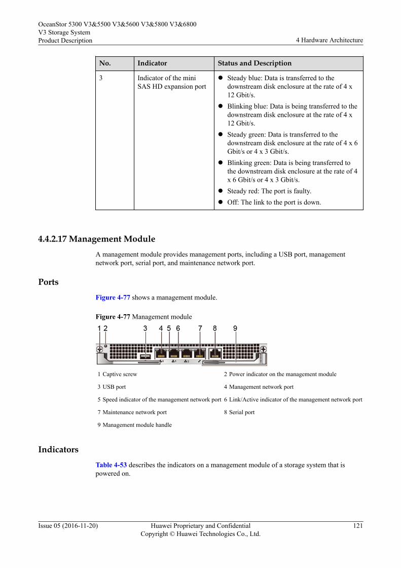
No. Indicator Status and Description
3 Indicator of the miniSAS HD expansion port
l Steady blue: Data is transferred to thedownstream disk enclosure at the rate of 4 x12 Gbit/s.
l Blinking blue: Data is being transferred to thedownstream disk enclosure at the rate of 4 x12 Gbit/s.
l Steady green: Data is transferred to thedownstream disk enclosure at the rate of 4 x 6Gbit/s or 4 x 3 Gbit/s.
l Blinking green: Data is being transferred tothe downstream disk enclosure at the rate of 4x 6 Gbit/s or 4 x 3 Gbit/s.
l Steady red: The port is faulty.l Off: The link to the port is down.
4.4.2.17 Management ModuleA management module provides management ports, including a USB port, managementnetwork port, serial port, and maintenance network port.
PortsFigure 4-77 shows a management module.
Figure 4-77 Management module
1 Captive screw 2 Power indicator on the management module
3 USB port 4 Management network port
5 Speed indicator of the management network port 6 Link/Active indicator of the management network port
7 Maintenance network port 8 Serial port
9 Management module handle
IndicatorsTable 4-53 describes the indicators on a management module of a storage system that ispowered on.
OceanStor 5300 V3&5500 V3&5600 V3&5800 V3&6800V3 Storage SystemProduct Description 4 Hardware Architecture
Issue 05 (2016-11-20) Huawei Proprietary and ConfidentialCopyright © Huawei Technologies Co., Ltd.
121
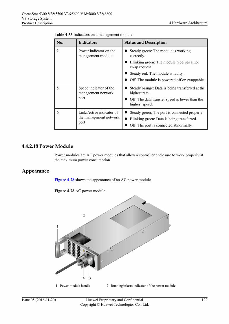
Table 4-53 Indicators on a management module
No. Indicators Status and Description
2 Power indicator on themanagement module
l Steady green: The module is workingcorrectly.
l Blinking green: The module receives a hotswap request.
l Steady red: The module is faulty.l Off: The module is powered off or swappable.
5 Speed indicator of themanagement networkport
l Steady orange: Data is being transferred at thehighest rate.
l Off: The data transfer speed is lower than thehighest speed.
6 Link/Active indicator ofthe management networkport
l Steady green: The port is connected properly.l Blinking green: Data is being transferred.l Off: The port is connected abnormally.
4.4.2.18 Power Module
Power modules are AC power modules that allow a controller enclosure to work properly atthe maximum power consumption.
Appearance
Figure 4-78 shows the appearance of an AC power module.
Figure 4-78 AC power module
1 Power module handle 2 Running/Alarm indicator of the power module
OceanStor 5300 V3&5500 V3&5600 V3&5800 V3&6800V3 Storage SystemProduct Description 4 Hardware Architecture
Issue 05 (2016-11-20) Huawei Proprietary and ConfidentialCopyright © Huawei Technologies Co., Ltd.
122
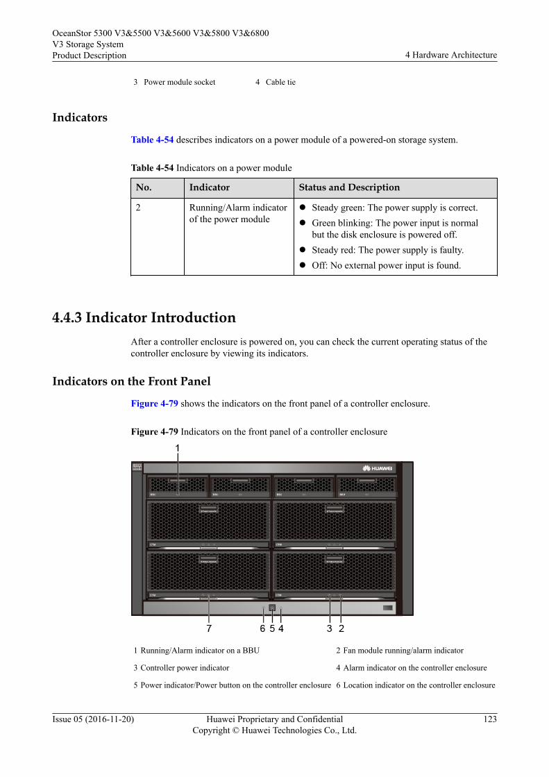
3 Power module socket 4 Cable tie
Indicators
Table 4-54 describes indicators on a power module of a powered-on storage system.
Table 4-54 Indicators on a power module
No. Indicator Status and Description
2 Running/Alarm indicatorof the power module
l Steady green: The power supply is correct.l Green blinking: The power input is normal
but the disk enclosure is powered off.l Steady red: The power supply is faulty.l Off: No external power input is found.
4.4.3 Indicator IntroductionAfter a controller enclosure is powered on, you can check the current operating status of thecontroller enclosure by viewing its indicators.
Indicators on the Front Panel
Figure 4-79 shows the indicators on the front panel of a controller enclosure.
Figure 4-79 Indicators on the front panel of a controller enclosure
1 Running/Alarm indicator on a BBU 2 Fan module running/alarm indicator
3 Controller power indicator 4 Alarm indicator on the controller enclosure
5 Power indicator/Power button on the controller enclosure 6 Location indicator on the controller enclosure
OceanStor 5300 V3&5500 V3&5600 V3&5800 V3&6800V3 Storage SystemProduct Description 4 Hardware Architecture
Issue 05 (2016-11-20) Huawei Proprietary and ConfidentialCopyright © Huawei Technologies Co., Ltd.
123
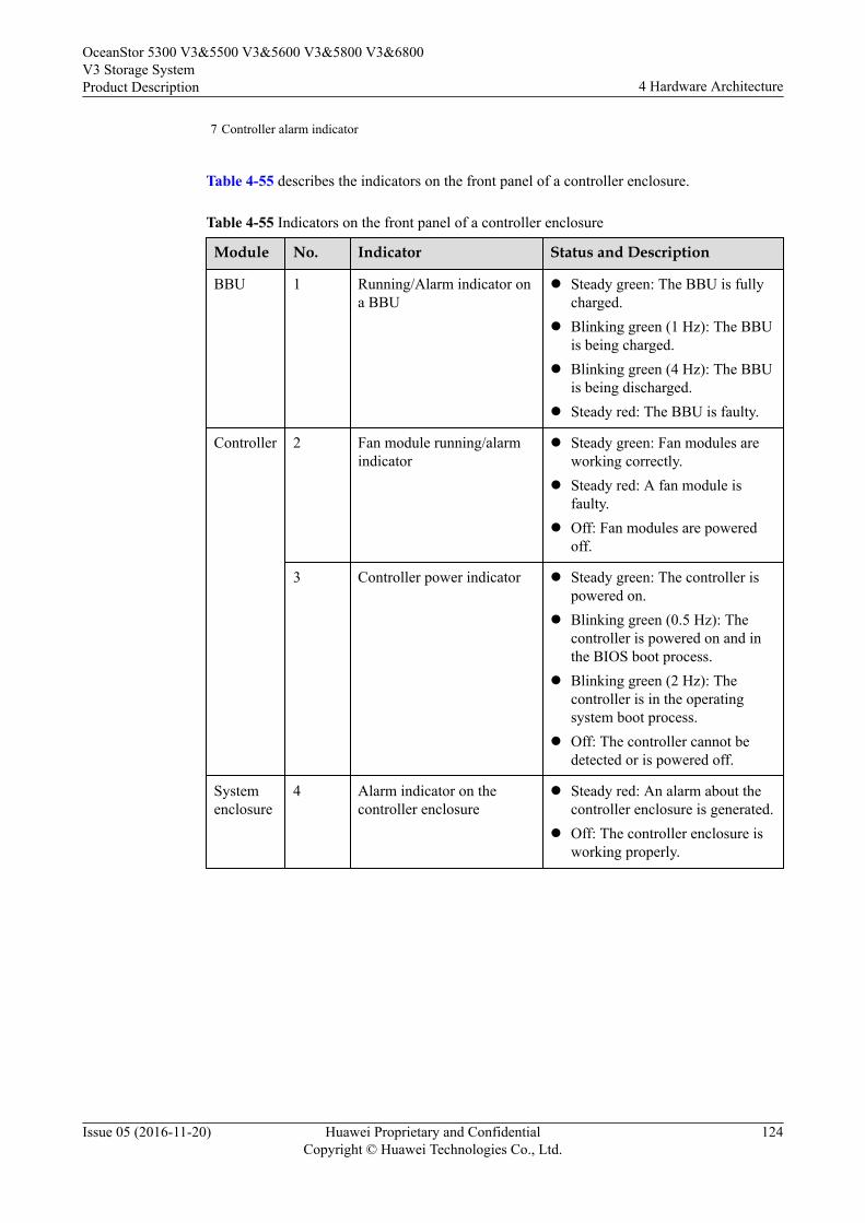
7 Controller alarm indicator
Table 4-55 describes the indicators on the front panel of a controller enclosure.
Table 4-55 Indicators on the front panel of a controller enclosure
Module No. Indicator Status and Description
BBU 1 Running/Alarm indicator ona BBU
l Steady green: The BBU is fullycharged.
l Blinking green (1 Hz): The BBUis being charged.
l Blinking green (4 Hz): The BBUis being discharged.
l Steady red: The BBU is faulty.
Controller 2 Fan module running/alarmindicator
l Steady green: Fan modules areworking correctly.
l Steady red: A fan module isfaulty.
l Off: Fan modules are poweredoff.
3 Controller power indicator l Steady green: The controller ispowered on.
l Blinking green (0.5 Hz): Thecontroller is powered on and inthe BIOS boot process.
l Blinking green (2 Hz): Thecontroller is in the operatingsystem boot process.
l Off: The controller cannot bedetected or is powered off.
Systemenclosure
4 Alarm indicator on thecontroller enclosure
l Steady red: An alarm about thecontroller enclosure is generated.
l Off: The controller enclosure isworking properly.
OceanStor 5300 V3&5500 V3&5600 V3&5800 V3&6800V3 Storage SystemProduct Description 4 Hardware Architecture
Issue 05 (2016-11-20) Huawei Proprietary and ConfidentialCopyright © Huawei Technologies Co., Ltd.
124
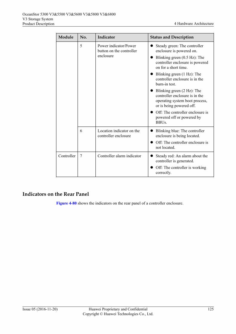
Module No. Indicator Status and Description
5 Power indicator/Powerbutton on the controllerenclosure
l Steady green: The controllerenclosure is powered on.
l Blinking green (0.5 Hz): Thecontroller enclosure is poweredon for a short time.
l Blinking green (1 Hz): Thecontroller enclosure is in theburn-in test.
l Blinking green (2 Hz): Thecontroller enclosure is in theoperating system boot process,or is being powered off.
l Off: The controller enclosure ispowered off or powered byBBUs.
6 Location indicator on thecontroller enclosure
l Blinking blue: The controllerenclosure is being located.
l Off: The controller enclosure isnot located.
Controller 7 Controller alarm indicator l Steady red: An alarm about thecontroller is generated.
l Off: The controller is workingcorrectly.
Indicators on the Rear PanelFigure 4-80 shows the indicators on the rear panel of a controller enclosure.
OceanStor 5300 V3&5500 V3&5600 V3&5800 V3&6800V3 Storage SystemProduct Description 4 Hardware Architecture
Issue 05 (2016-11-20) Huawei Proprietary and ConfidentialCopyright © Huawei Technologies Co., Ltd.
125
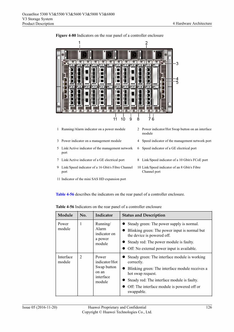
Figure 4-80 Indicators on the rear panel of a controller enclosure
1 Running/Alarm indicator on a power module 2 Power indicator/Hot Swap button on an interfacemodule
3 Power indicator on a management module 4 Speed indicator of the management network port
5 Link/Active indicator of the management networkport
6 Speed indicator of a GE electrical port
7 Link/Active indicator of a GE electrical port 8 Link/Speed indicator of a 10 Gbit/s FCoE port
9 Link/Speed indicator of a 16 Gbit/s Fibre Channelport
10 Link/Speed indicator of an 8 Gbit/s FibreChannel port
11 Indicator of the mini SAS HD expansion port
Table 4-56 describes the indicators on the rear panel of a controller enclosure.
Table 4-56 Indicators on the rear panel of a controller enclosure
Module No. Indicator Status and Description
Powermodule
1 Running/Alarmindicator ona powermodule
l Steady green: The power supply is normal.l Blinking green: The power input is normal but
the device is powered off.l Steady red: The power module is faulty.l Off: No external power input is available.
Interfacemodule
2 Powerindicator/HotSwap buttonon aninterfacemodule
l Steady green: The interface module is workingcorrectly.
l Blinking green: The interface module receives ahot swap request.
l Steady red: The interface module is faulty.l Off: The interface module is powered off or
swappable.
OceanStor 5300 V3&5500 V3&5600 V3&5800 V3&6800V3 Storage SystemProduct Description 4 Hardware Architecture
Issue 05 (2016-11-20) Huawei Proprietary and ConfidentialCopyright © Huawei Technologies Co., Ltd.
126
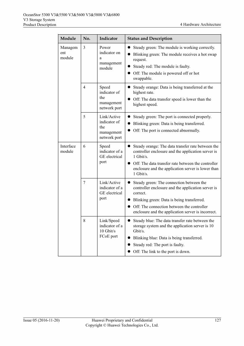
Module No. Indicator Status and Description
Managementmodule
3 Powerindicator onamanagementmodule
l Steady green: The module is working correctly.l Blinking green: The module receives a hot swap
request.l Steady red: The module is faulty.l Off: The module is powered off or hot
swappable.
4 Speedindicator ofthemanagementnetwork port
l Steady orange: Data is being transferred at thehighest rate.
l Off: The data transfer speed is lower than thehighest speed.
5 Link/Activeindicator ofthemanagementnetwork port
l Steady green: The port is connected properly.l Blinking green: Data is being transferred.l Off: The port is connected abnormally.
Interfacemodule
6 Speedindicator of aGE electricalport
l Steady orange: The data transfer rate between thecontroller enclosure and the application server is1 Gbit/s.
l Off: The data transfer rate between the controllerenclosure and the application server is lower than1 Gbit/s.
7 Link/Activeindicator of aGE electricalport
l Steady green: The connection between thecontroller enclosure and the application server iscorrect.
l Blinking green: Data is being transferred.l Off: The connection between the controller
enclosure and the application server is incorrect.
8 Link/Speedindicator of a10 Gbit/sFCoE port
l Steady blue: The data transfer rate between thestorage system and the application server is 10Gbit/s.
l Blinking blue: Data is being transferred.l Steady red: The port is faulty.l Off: The link to the port is down.
OceanStor 5300 V3&5500 V3&5600 V3&5800 V3&6800V3 Storage SystemProduct Description 4 Hardware Architecture
Issue 05 (2016-11-20) Huawei Proprietary and ConfidentialCopyright © Huawei Technologies Co., Ltd.
127
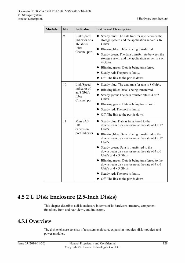
Module No. Indicator Status and Description
9 Link/Speedindicator of a16 Gbit/sFibreChannel port
l Steady blue: The data transfer rate between thestorage system and the application server is 16Gbit/s.
l Blinking blue: Data is being transferred.l Steady green: The data transfer rate between the
storage system and the application server is 8 or4 Gbit/s.
l Blinking green: Data is being transferred.l Steady red: The port is faulty.l Off: The link to the port is down.
10 Link/Speedindicator ofan 8 Gbit/sFibreChannel port
l Steady blue: The data transfer rate is 8 Gbit/s.l Blinking blue: Data is being transferred.l Steady green: The data transfer rate is 4 or 2
Gbit/s.l Blinking green: Data is being transferred.l Steady red: The port is faulty.l Off: The link to the port is down.
11 Mini SASHDexpansionport indicator
l Steady blue: Data is transferred to thedownstream disk enclosure at the rate of 4 x 12Gbit/s.
l Blinking blue: Data is being transferred to thedownstream disk enclosure at the rate of 4 x 12Gbit/s.
l Steady green: Data is transferred to thedownstream disk enclosure at the rate of 4 x 6Gbit/s or 4 x 3 Gbit/s.
l Blinking green: Data is being transferred to thedownstream disk enclosure at the rate of 4 x 6Gbit/s or 4 x 3 Gbit/s.
l Steady red: The port is faulty.l Off: The link to the port is down.
4.5 2 U Disk Enclosure (2.5-Inch Disks)This chapter describes a disk enclosure in terms of its hardware structure, componentfunctions, front and rear views, and indicators.
4.5.1 OverviewThe disk enclosure consists of a system enclosure, expansion modules, disk modules, andpower modules.
OceanStor 5300 V3&5500 V3&5600 V3&5800 V3&6800V3 Storage SystemProduct Description 4 Hardware Architecture
Issue 05 (2016-11-20) Huawei Proprietary and ConfidentialCopyright © Huawei Technologies Co., Ltd.
128
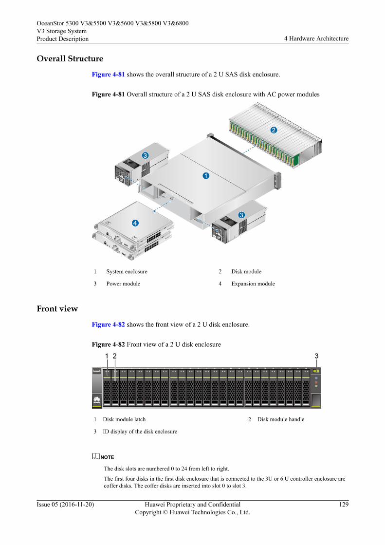
Overall Structure
Figure 4-81 shows the overall structure of a 2 U SAS disk enclosure.
Figure 4-81 Overall structure of a 2 U SAS disk enclosure with AC power modules
1 System enclosure 2 Disk module
3 Power module 4 Expansion module
Front view
Figure 4-82 shows the front view of a 2 U disk enclosure.
Figure 4-82 Front view of a 2 U disk enclosure
1 Disk module latch 2 Disk module handle
3 ID display of the disk enclosure
NOTE
The disk slots are numbered 0 to 24 from left to right.
The first four disks in the first disk enclosure that is connected to the 3U or 6 U controller enclosure arecoffer disks. The coffer disks are inserted into slot 0 to slot 3.
OceanStor 5300 V3&5500 V3&5600 V3&5800 V3&6800V3 Storage SystemProduct Description 4 Hardware Architecture
Issue 05 (2016-11-20) Huawei Proprietary and ConfidentialCopyright © Huawei Technologies Co., Ltd.
129
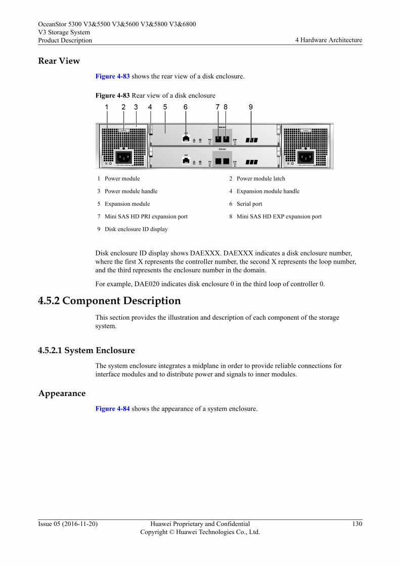
Rear ViewFigure 4-83 shows the rear view of a disk enclosure.
Figure 4-83 Rear view of a disk enclosure
1 Power module 2 Power module latch
3 Power module handle 4 Expansion module handle
5 Expansion module 6 Serial port
7 Mini SAS HD PRI expansion port 8 Mini SAS HD EXP expansion port
9 Disk enclosure ID display
Disk enclosure ID display shows DAEXXX. DAEXXX indicates a disk enclosure number,where the first X represents the controller number, the second X represents the loop number,and the third represents the enclosure number in the domain.
For example, DAE020 indicates disk enclosure 0 in the third loop of controller 0.
4.5.2 Component DescriptionThis section provides the illustration and description of each component of the storagesystem.
4.5.2.1 System EnclosureThe system enclosure integrates a midplane in order to provide reliable connections forinterface modules and to distribute power and signals to inner modules.
AppearanceFigure 4-84 shows the appearance of a system enclosure.
OceanStor 5300 V3&5500 V3&5600 V3&5800 V3&6800V3 Storage SystemProduct Description 4 Hardware Architecture
Issue 05 (2016-11-20) Huawei Proprietary and ConfidentialCopyright © Huawei Technologies Co., Ltd.
130
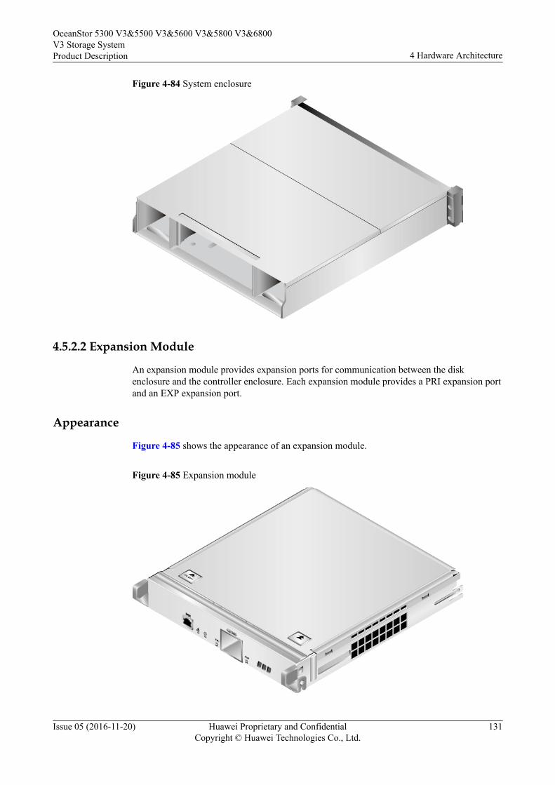
Figure 4-84 System enclosure
4.5.2.2 Expansion Module
An expansion module provides expansion ports for communication between the diskenclosure and the controller enclosure. Each expansion module provides a PRI expansion portand an EXP expansion port.
Appearance
Figure 4-85 shows the appearance of an expansion module.
Figure 4-85 Expansion module
OceanStor 5300 V3&5500 V3&5600 V3&5800 V3&6800V3 Storage SystemProduct Description 4 Hardware Architecture
Issue 05 (2016-11-20) Huawei Proprietary and ConfidentialCopyright © Huawei Technologies Co., Ltd.
131
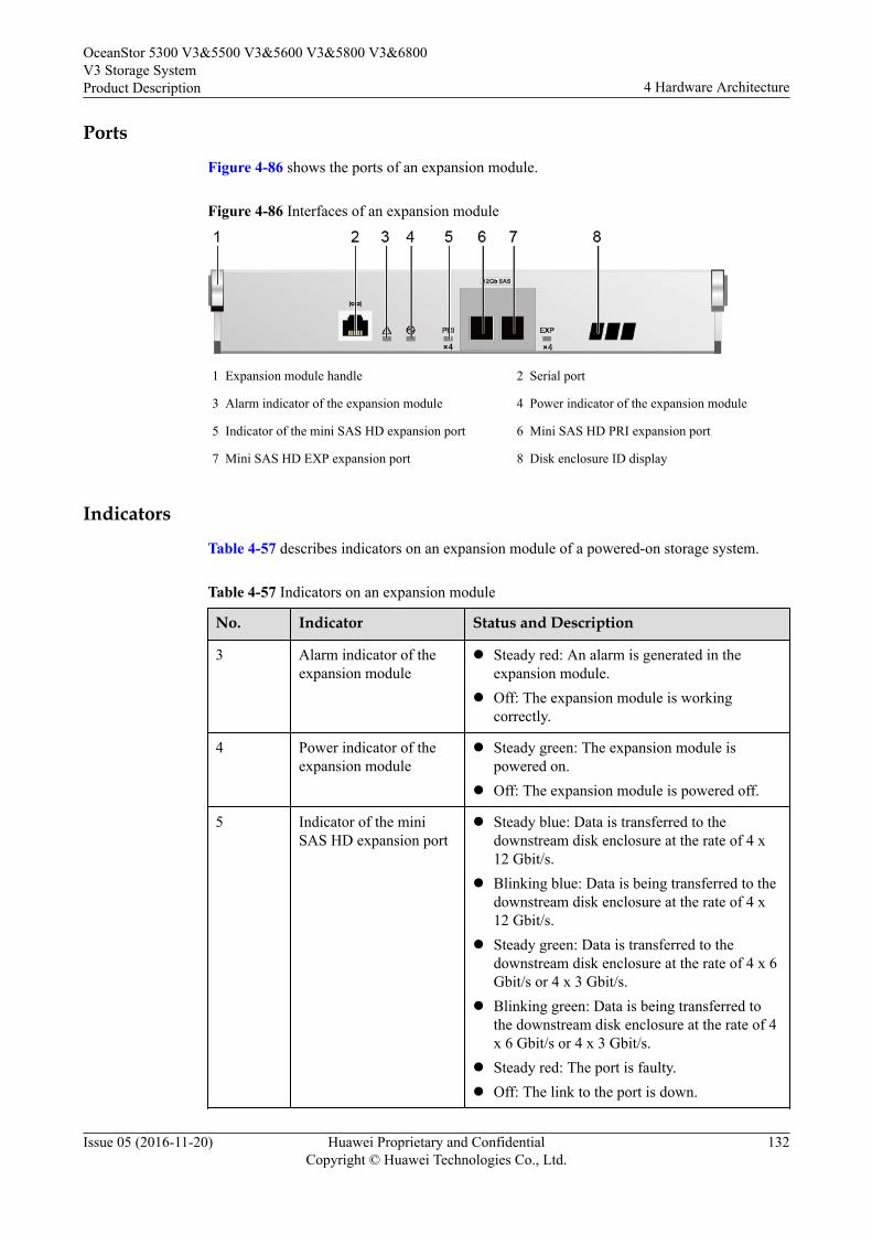
Ports
Figure 4-86 shows the ports of an expansion module.
Figure 4-86 Interfaces of an expansion module
1 Expansion module handle 2 Serial port
3 Alarm indicator of the expansion module 4 Power indicator of the expansion module
5 Indicator of the mini SAS HD expansion port 6 Mini SAS HD PRI expansion port
7 Mini SAS HD EXP expansion port 8 Disk enclosure ID display
Indicators
Table 4-57 describes indicators on an expansion module of a powered-on storage system.
Table 4-57 Indicators on an expansion module
No. Indicator Status and Description
3 Alarm indicator of theexpansion module
l Steady red: An alarm is generated in theexpansion module.
l Off: The expansion module is workingcorrectly.
4 Power indicator of theexpansion module
l Steady green: The expansion module ispowered on.
l Off: The expansion module is powered off.
5 Indicator of the miniSAS HD expansion port
l Steady blue: Data is transferred to thedownstream disk enclosure at the rate of 4 x12 Gbit/s.
l Blinking blue: Data is being transferred to thedownstream disk enclosure at the rate of 4 x12 Gbit/s.
l Steady green: Data is transferred to thedownstream disk enclosure at the rate of 4 x 6Gbit/s or 4 x 3 Gbit/s.
l Blinking green: Data is being transferred tothe downstream disk enclosure at the rate of 4x 6 Gbit/s or 4 x 3 Gbit/s.
l Steady red: The port is faulty.l Off: The link to the port is down.
OceanStor 5300 V3&5500 V3&5600 V3&5800 V3&6800V3 Storage SystemProduct Description 4 Hardware Architecture
Issue 05 (2016-11-20) Huawei Proprietary and ConfidentialCopyright © Huawei Technologies Co., Ltd.
132
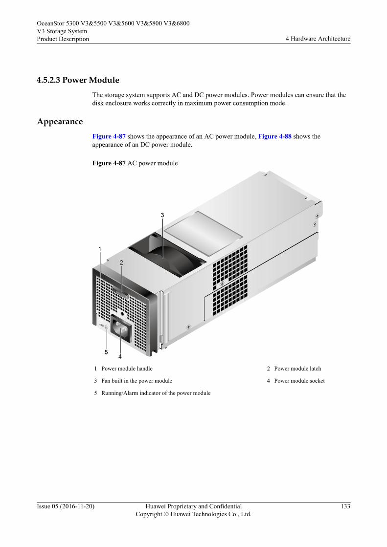
4.5.2.3 Power ModuleThe storage system supports AC and DC power modules. Power modules can ensure that thedisk enclosure works correctly in maximum power consumption mode.
AppearanceFigure 4-87 shows the appearance of an AC power module, Figure 4-88 shows theappearance of an DC power module.
Figure 4-87 AC power module
1 Power module handle 2 Power module latch
3 Fan built in the power module 4 Power module socket
5 Running/Alarm indicator of the power module
OceanStor 5300 V3&5500 V3&5600 V3&5800 V3&6800V3 Storage SystemProduct Description 4 Hardware Architecture
Issue 05 (2016-11-20) Huawei Proprietary and ConfidentialCopyright © Huawei Technologies Co., Ltd.
133
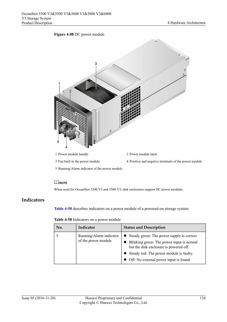
Figure 4-88 DC power module
1 Power module handle 2 Power module latch
3 Fan built in the power module 4 Positive and negative terminals of the power module
5 Running/Alarm indicator of the power module
NOTE
When used for OceanStor 5300 V3 and 5500 V3, disk enclosures support DC power modules.
IndicatorsTable 4-58 describes indicators on a power module of a powered-on storage system.
Table 4-58 Indicators on a power module
No. Indicator Status and Description
5 Running/Alarm indicatorof the power module
l Steady green: The power supply is correct.l Blinking green: The power input is normal
but the disk enclosure is powered off.l Steady red: The power module is faulty.l Off: No external power input is found.
OceanStor 5300 V3&5500 V3&5600 V3&5800 V3&6800V3 Storage SystemProduct Description 4 Hardware Architecture
Issue 05 (2016-11-20) Huawei Proprietary and ConfidentialCopyright © Huawei Technologies Co., Ltd.
134
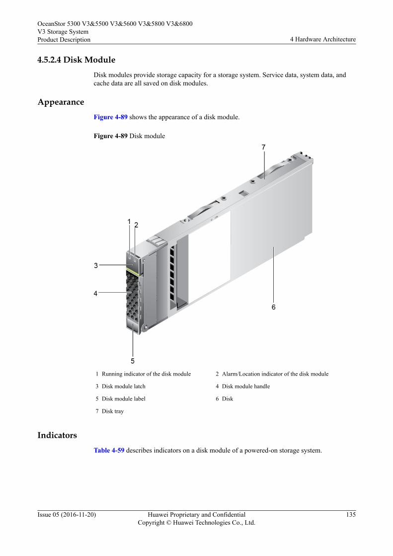
4.5.2.4 Disk ModuleDisk modules provide storage capacity for a storage system. Service data, system data, andcache data are all saved on disk modules.
AppearanceFigure 4-89 shows the appearance of a disk module.
Figure 4-89 Disk module
1 Running indicator of the disk module 2 Alarm/Location indicator of the disk module
3 Disk module latch 4 Disk module handle
5 Disk module label 6 Disk
7 Disk tray
IndicatorsTable 4-59 describes indicators on a disk module of a powered-on storage system.
OceanStor 5300 V3&5500 V3&5600 V3&5800 V3&6800V3 Storage SystemProduct Description 4 Hardware Architecture
Issue 05 (2016-11-20) Huawei Proprietary and ConfidentialCopyright © Huawei Technologies Co., Ltd.
135
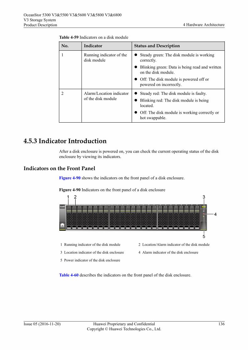
Table 4-59 Indicators on a disk module
No. Indicator Status and Description
1 Running indicator of thedisk module
l Steady green: The disk module is workingcorrectly.
l Blinking green: Data is being read and writtenon the disk module.
l Off: The disk module is powered off orpowered on incorrectly.
2 Alarm/Location indicatorof the disk module
l Steady red: The disk module is faulty.l Blinking red: The disk module is being
located.l Off: The disk module is working correctly or
hot swappable.
4.5.3 Indicator IntroductionAfter a disk enclosure is powered on, you can check the current operating status of the diskenclosure by viewing its indicators.
Indicators on the Front PanelFigure 4-90 shows the indicators on the front panel of a disk enclosure.
Figure 4-90 Indicators on the front panel of a disk enclosure
1 Running indicator of the disk module 2 Location/Alarm indicator of the disk module
3 Location indicator of the disk enclosure 4 Alarm indicator of the disk enclosure
5 Power indicator of the disk enclosure
Table 4-60 describes the indicators on the front panel of the disk enclosure.
OceanStor 5300 V3&5500 V3&5600 V3&5800 V3&6800V3 Storage SystemProduct Description 4 Hardware Architecture
Issue 05 (2016-11-20) Huawei Proprietary and ConfidentialCopyright © Huawei Technologies Co., Ltd.
136
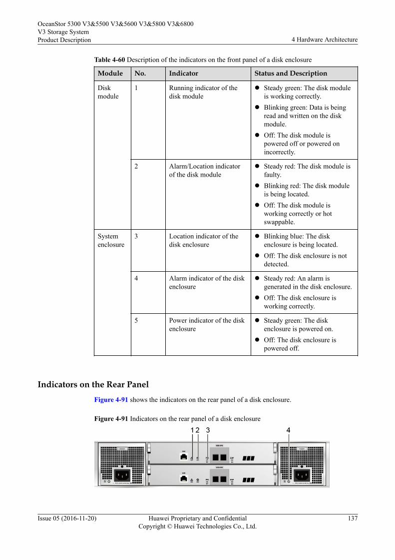
Table 4-60 Description of the indicators on the front panel of a disk enclosure
Module No. Indicator Status and Description
Diskmodule
1 Running indicator of thedisk module
l Steady green: The disk moduleis working correctly.
l Blinking green: Data is beingread and written on the diskmodule.
l Off: The disk module ispowered off or powered onincorrectly.
2 Alarm/Location indicatorof the disk module
l Steady red: The disk module isfaulty.
l Blinking red: The disk moduleis being located.
l Off: The disk module isworking correctly or hotswappable.
Systemenclosure
3 Location indicator of thedisk enclosure
l Blinking blue: The diskenclosure is being located.
l Off: The disk enclosure is notdetected.
4 Alarm indicator of the diskenclosure
l Steady red: An alarm isgenerated in the disk enclosure.
l Off: The disk enclosure isworking correctly.
5 Power indicator of the diskenclosure
l Steady green: The diskenclosure is powered on.
l Off: The disk enclosure ispowered off.
Indicators on the Rear PanelFigure 4-91 shows the indicators on the rear panel of a disk enclosure.
Figure 4-91 Indicators on the rear panel of a disk enclosure
OceanStor 5300 V3&5500 V3&5600 V3&5800 V3&6800V3 Storage SystemProduct Description 4 Hardware Architecture
Issue 05 (2016-11-20) Huawei Proprietary and ConfidentialCopyright © Huawei Technologies Co., Ltd.
137
1 Alarm indicator of the expansion module 2 Power indicator of the expansion module
3 Indicator of the mini SAS HD expansionport
4 Running/Alarm indicator of the powermodule
Table 4-61 describes the indicators on the rear panel of the disk enclosure.
Table 4-61 Description of the indicators on the rear panel of a disk enclosure
Module No. Indicator Status and Description
Expansionmodule
1 Alarmindicator oftheexpansionmodule
l Steady red: An alarm is generated on theexpansion module.
l Off: The expansion module is workingcorrectly.
2 Powerindicator oftheexpansionmodule
l Steady green: The expansion module ispowered on.
l Off: The expansion module is powered off.
3 Indicator ofthe miniSAS HDexpansionport
l Steady blue: Data is transferred to thedownstream disk enclosure at the rate of 4 x12 Gbit/s.
l Blinking blue: Data is being transferred to thedownstream disk enclosure at the rate of 4 x12 Gbit/s.
l Steady green: Data is transferred to thedownstream disk enclosure at the rate of 4 x 6Gbit/s or 4 x 3 Gbit/s.
l Blinking green: Data is being transferred tothe downstream disk enclosure at the rate of 4x 6 Gbit/s or 4 x 3 Gbit/s.
l Steady red: The port is faulty.l Off: The link to the port is down.
Powermodule
4 Running/Alarmindicator ofthe powermodule
l Steady green: The power supply is correct.l Blinking green: The power input is normal but
the disk enclosure is powered off.l Steady red: The power supply is faulty.l Off: No external power input is found.
4.6 4 U Disk Enclosure (3.5-Inch Disks)This chapter describes a disk enclosure in terms of its hardware structure, componentfunctions, front and rear views, and indicators.
OceanStor 5300 V3&5500 V3&5600 V3&5800 V3&6800V3 Storage SystemProduct Description 4 Hardware Architecture
Issue 05 (2016-11-20) Huawei Proprietary and ConfidentialCopyright © Huawei Technologies Co., Ltd.
138
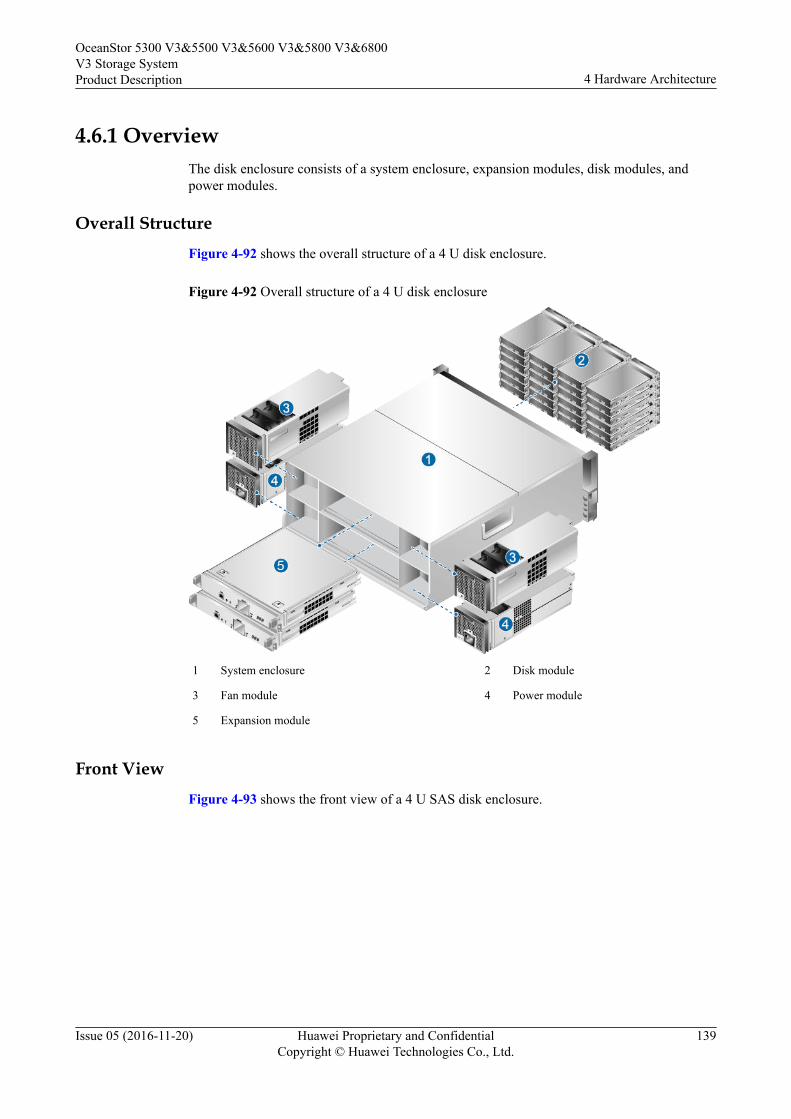
4.6.1 OverviewThe disk enclosure consists of a system enclosure, expansion modules, disk modules, andpower modules.
Overall StructureFigure 4-92 shows the overall structure of a 4 U disk enclosure.
Figure 4-92 Overall structure of a 4 U disk enclosure
1 System enclosure 2 Disk module
3 Fan module 4 Power module
5 Expansion module
Front ViewFigure 4-93 shows the front view of a 4 U SAS disk enclosure.
OceanStor 5300 V3&5500 V3&5600 V3&5800 V3&6800V3 Storage SystemProduct Description 4 Hardware Architecture
Issue 05 (2016-11-20) Huawei Proprietary and ConfidentialCopyright © Huawei Technologies Co., Ltd.
139
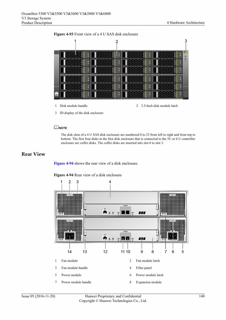
Figure 4-93 Front view of a 4 U SAS disk enclosure
1 Disk module handle 2 3.5-Inch disk module latch
3 ID display of the disk enclosure
NOTE
The disk slots of a 4 U SAS disk enclosure are numbered 0 to 23 from left to right and from top tobottom. The first four disks in the first disk enclosure that is connected to the 3U or 6 U controllerenclosure are coffer disks. The coffer disks are inserted into slot 0 to slot 3.
Rear View
Figure 4-94 shows the rear view of a disk enclosure.
Figure 4-94 Rear view of a disk enclosure
1 Fan module 2 Fan module latch
3 Fan module handle 4 Filler panel
5 Power module 6 Power module latch
7 Power module handle 8 Expansion module
OceanStor 5300 V3&5500 V3&5600 V3&5800 V3&6800V3 Storage SystemProduct Description 4 Hardware Architecture
Issue 05 (2016-11-20) Huawei Proprietary and ConfidentialCopyright © Huawei Technologies Co., Ltd.
140
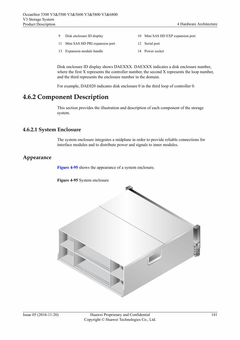
9 Disk enclosure ID display 10 Mini SAS HD EXP expansion port
11 Mini SAS HD PRI expansion port 12 Serial port
13 Expansion module handle 14 Power socket
Disk enclosure ID display shows DAEXXX. DAEXXX indicates a disk enclosure number,where the first X represents the controller number, the second X represents the loop number,and the third represents the enclosure number in the domain.
For example, DAE020 indicates disk enclosure 0 in the third loop of controller 0.
4.6.2 Component DescriptionThis section provides the illustration and description of each component of the storagesystem.
4.6.2.1 System Enclosure
The system enclosure integrates a midplane in order to provide reliable connections forinterface modules and to distribute power and signals to inner modules.
Appearance
Figure 4-95 shows the appearance of a system enclosure.
Figure 4-95 System enclosure
OceanStor 5300 V3&5500 V3&5600 V3&5800 V3&6800V3 Storage SystemProduct Description 4 Hardware Architecture
Issue 05 (2016-11-20) Huawei Proprietary and ConfidentialCopyright © Huawei Technologies Co., Ltd.
141
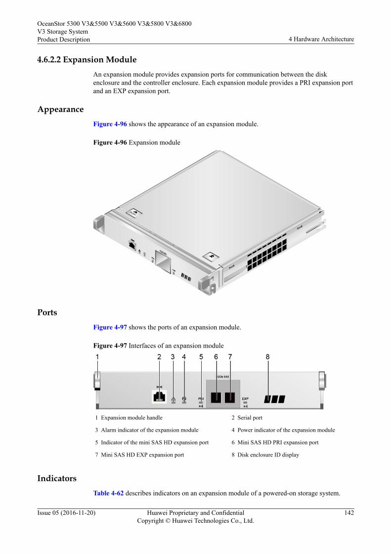
4.6.2.2 Expansion ModuleAn expansion module provides expansion ports for communication between the diskenclosure and the controller enclosure. Each expansion module provides a PRI expansion portand an EXP expansion port.
AppearanceFigure 4-96 shows the appearance of an expansion module.
Figure 4-96 Expansion module
PortsFigure 4-97 shows the ports of an expansion module.
Figure 4-97 Interfaces of an expansion module
1 Expansion module handle 2 Serial port
3 Alarm indicator of the expansion module 4 Power indicator of the expansion module
5 Indicator of the mini SAS HD expansion port 6 Mini SAS HD PRI expansion port
7 Mini SAS HD EXP expansion port 8 Disk enclosure ID display
IndicatorsTable 4-62 describes indicators on an expansion module of a powered-on storage system.
OceanStor 5300 V3&5500 V3&5600 V3&5800 V3&6800V3 Storage SystemProduct Description 4 Hardware Architecture
Issue 05 (2016-11-20) Huawei Proprietary and ConfidentialCopyright © Huawei Technologies Co., Ltd.
142
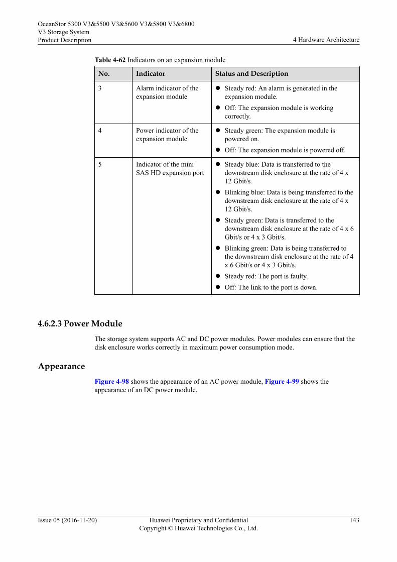
Table 4-62 Indicators on an expansion module
No. Indicator Status and Description
3 Alarm indicator of theexpansion module
l Steady red: An alarm is generated in theexpansion module.
l Off: The expansion module is workingcorrectly.
4 Power indicator of theexpansion module
l Steady green: The expansion module ispowered on.
l Off: The expansion module is powered off.
5 Indicator of the miniSAS HD expansion port
l Steady blue: Data is transferred to thedownstream disk enclosure at the rate of 4 x12 Gbit/s.
l Blinking blue: Data is being transferred to thedownstream disk enclosure at the rate of 4 x12 Gbit/s.
l Steady green: Data is transferred to thedownstream disk enclosure at the rate of 4 x 6Gbit/s or 4 x 3 Gbit/s.
l Blinking green: Data is being transferred tothe downstream disk enclosure at the rate of 4x 6 Gbit/s or 4 x 3 Gbit/s.
l Steady red: The port is faulty.l Off: The link to the port is down.
4.6.2.3 Power ModuleThe storage system supports AC and DC power modules. Power modules can ensure that thedisk enclosure works correctly in maximum power consumption mode.
AppearanceFigure 4-98 shows the appearance of an AC power module, Figure 4-99 shows theappearance of an DC power module.
OceanStor 5300 V3&5500 V3&5600 V3&5800 V3&6800V3 Storage SystemProduct Description 4 Hardware Architecture
Issue 05 (2016-11-20) Huawei Proprietary and ConfidentialCopyright © Huawei Technologies Co., Ltd.
143
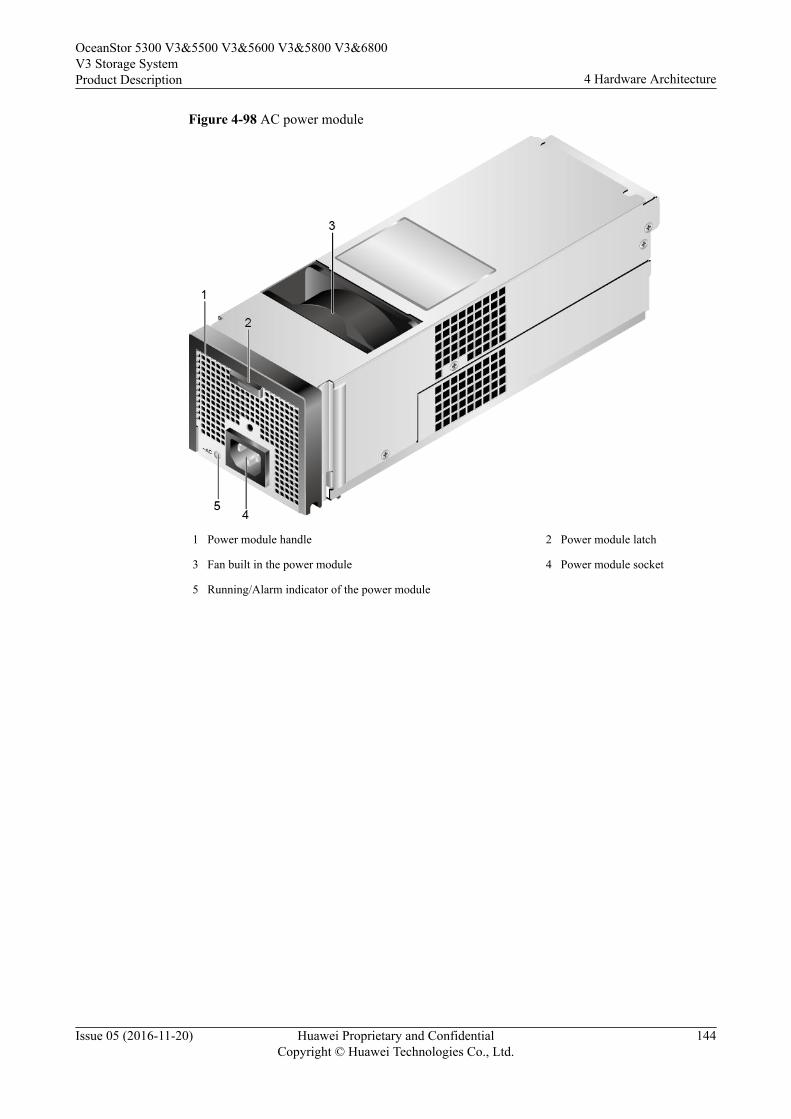
Figure 4-98 AC power module
1 Power module handle 2 Power module latch
3 Fan built in the power module 4 Power module socket
5 Running/Alarm indicator of the power module
OceanStor 5300 V3&5500 V3&5600 V3&5800 V3&6800V3 Storage SystemProduct Description 4 Hardware Architecture
Issue 05 (2016-11-20) Huawei Proprietary and ConfidentialCopyright © Huawei Technologies Co., Ltd.
144

Figure 4-99 DC power module
1 Power module handle 2 Power module latch
3 Fan built in the power module 4 Positive and negative terminals of the power module
5 Running/Alarm indicator of the power module
NOTE
When used for OceanStor 5300 V3 and 5500 V3, disk enclosures support DC power modules.
IndicatorsTable 4-63 describes indicators on a power module of a powered-on storage system.
Table 4-63 Indicators on a power module
No. Indicator Status and Description
5 Running/Alarm indicatorof the power module
l Steady green: The power supply is correct.l Blinking green: The power input is normal
but the disk enclosure is powered off.l Steady red: The power module is faulty.l Off: No external power input is found.
OceanStor 5300 V3&5500 V3&5600 V3&5800 V3&6800V3 Storage SystemProduct Description 4 Hardware Architecture
Issue 05 (2016-11-20) Huawei Proprietary and ConfidentialCopyright © Huawei Technologies Co., Ltd.
145
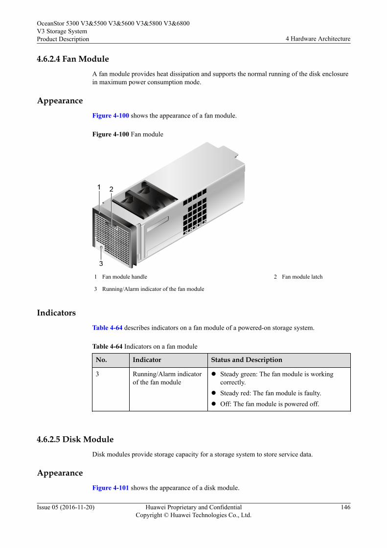
4.6.2.4 Fan Module
A fan module provides heat dissipation and supports the normal running of the disk enclosurein maximum power consumption mode.
Appearance
Figure 4-100 shows the appearance of a fan module.
Figure 4-100 Fan module
1 Fan module handle 2 Fan module latch
3 Running/Alarm indicator of the fan module
Indicators
Table 4-64 describes indicators on a fan module of a powered-on storage system.
Table 4-64 Indicators on a fan module
No. Indicator Status and Description
3 Running/Alarm indicatorof the fan module
l Steady green: The fan module is workingcorrectly.
l Steady red: The fan module is faulty.l Off: The fan module is powered off.
4.6.2.5 Disk Module
Disk modules provide storage capacity for a storage system to store service data.
Appearance
Figure 4-101 shows the appearance of a disk module.
OceanStor 5300 V3&5500 V3&5600 V3&5800 V3&6800V3 Storage SystemProduct Description 4 Hardware Architecture
Issue 05 (2016-11-20) Huawei Proprietary and ConfidentialCopyright © Huawei Technologies Co., Ltd.
146
Figure 4-101 Disk module
1 Disk module label 2 Disk module handle
3 Disk module latch 4 Alarm/Location indicator of the disk module
5 Running indicator of the disk module 6 Disk tray
7 Disk
IndicatorsTable 4-65 describes indicators on a disk module of a powered-on storage system.
Table 4-65 Indicators on a disk module
No. Indicator Status and Description
4 Alarm/Location indicatorof the disk module
l Steady red: The disk module is faulty.l Blinking red: The disk module is being
located.l Off: The disk module is working correctly or
hot swappable.
5 Running indicator of thedisk module
l Steady green: The disk module is workingcorrectly.
l Blinking green: Data is being read and writtenon the disk module.
l Off: The disk module is powered off orpowered on incorrectly.
OceanStor 5300 V3&5500 V3&5600 V3&5800 V3&6800V3 Storage SystemProduct Description 4 Hardware Architecture
Issue 05 (2016-11-20) Huawei Proprietary and ConfidentialCopyright © Huawei Technologies Co., Ltd.
147
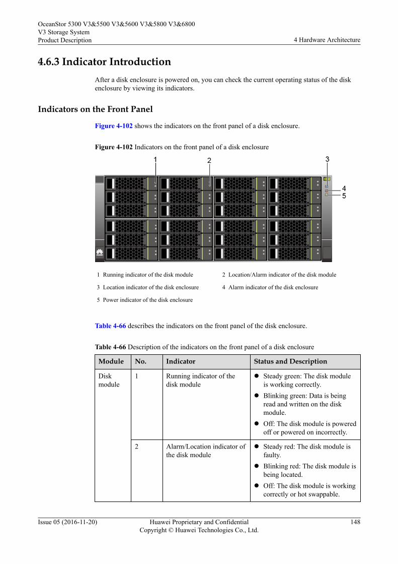
4.6.3 Indicator IntroductionAfter a disk enclosure is powered on, you can check the current operating status of the diskenclosure by viewing its indicators.
Indicators on the Front Panel
Figure 4-102 shows the indicators on the front panel of a disk enclosure.
Figure 4-102 Indicators on the front panel of a disk enclosure
1 Running indicator of the disk module 2 Location/Alarm indicator of the disk module
3 Location indicator of the disk enclosure 4 Alarm indicator of the disk enclosure
5 Power indicator of the disk enclosure
Table 4-66 describes the indicators on the front panel of the disk enclosure.
Table 4-66 Description of the indicators on the front panel of a disk enclosure
Module No. Indicator Status and Description
Diskmodule
1 Running indicator of thedisk module
l Steady green: The disk moduleis working correctly.
l Blinking green: Data is beingread and written on the diskmodule.
l Off: The disk module is poweredoff or powered on incorrectly.
2 Alarm/Location indicator ofthe disk module
l Steady red: The disk module isfaulty.
l Blinking red: The disk module isbeing located.
l Off: The disk module is workingcorrectly or hot swappable.
OceanStor 5300 V3&5500 V3&5600 V3&5800 V3&6800V3 Storage SystemProduct Description 4 Hardware Architecture
Issue 05 (2016-11-20) Huawei Proprietary and ConfidentialCopyright © Huawei Technologies Co., Ltd.
148
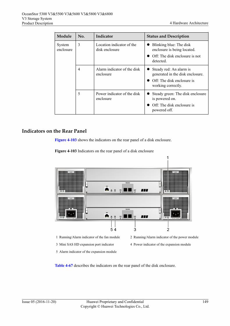
Module No. Indicator Status and Description
Systemenclosure
3 Location indicator of thedisk enclosure
l Blinking blue: The diskenclosure is being located.
l Off: The disk enclosure is notdetected.
4 Alarm indicator of the diskenclosure
l Steady red: An alarm isgenerated in the disk enclosure.
l Off: The disk enclosure isworking correctly.
5 Power indicator of the diskenclosure
l Steady green: The disk enclosureis powered on.
l Off: The disk enclosure ispowered off.
Indicators on the Rear PanelFigure 4-103 shows the indicators on the rear panel of a disk enclosure.
Figure 4-103 Indicators on the rear panel of a disk enclosure
1 Running/Alarm indicator of the fan module 2 Running/Alarm indicator of the power module
3 Mini SAS HD expansion port indicator 4 Power indicator of the expansion module
5 Alarm indicator of the expansion module
Table 4-67 describes the indicators on the rear panel of the disk enclosure.
OceanStor 5300 V3&5500 V3&5600 V3&5800 V3&6800V3 Storage SystemProduct Description 4 Hardware Architecture
Issue 05 (2016-11-20) Huawei Proprietary and ConfidentialCopyright © Huawei Technologies Co., Ltd.
149
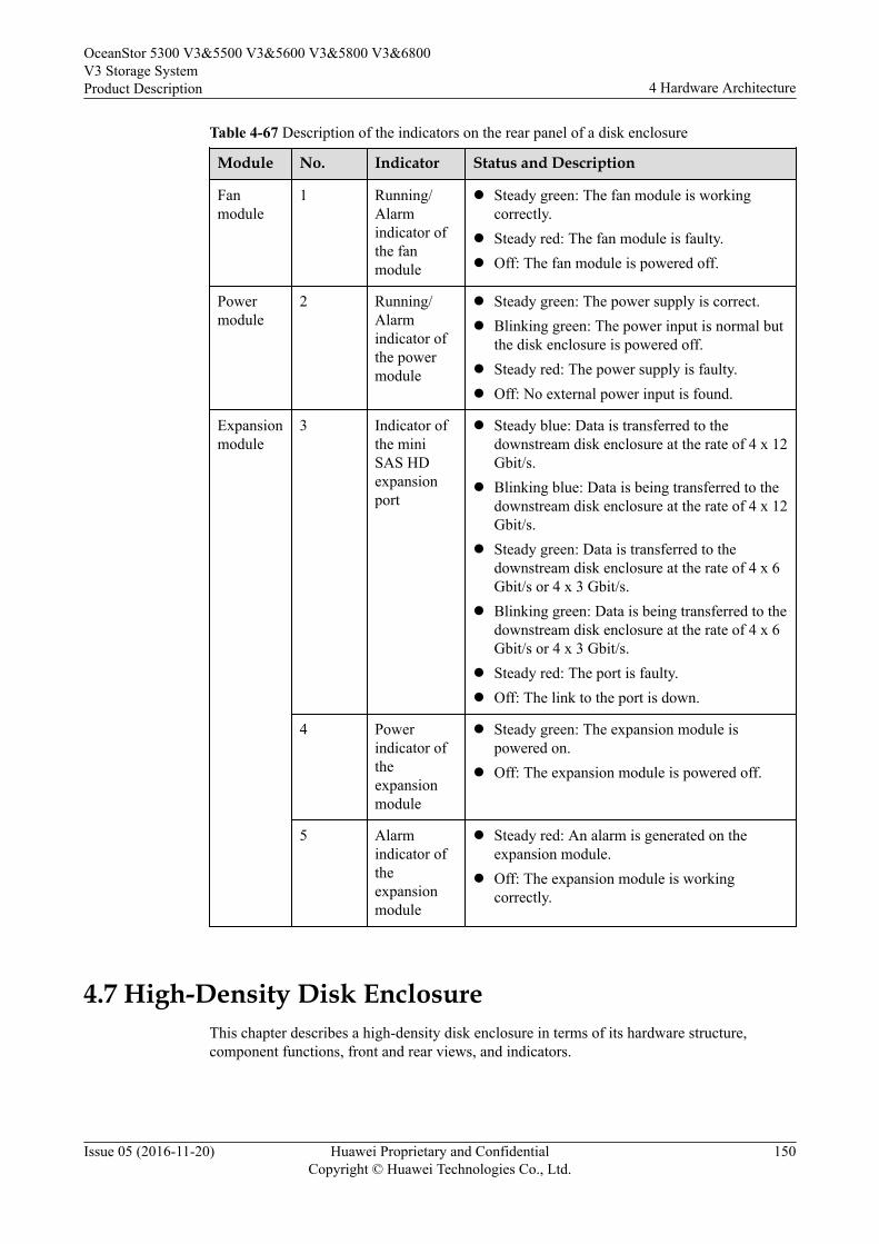
Table 4-67 Description of the indicators on the rear panel of a disk enclosure
Module No. Indicator Status and Description
Fanmodule
1 Running/Alarmindicator ofthe fanmodule
l Steady green: The fan module is workingcorrectly.
l Steady red: The fan module is faulty.l Off: The fan module is powered off.
Powermodule
2 Running/Alarmindicator ofthe powermodule
l Steady green: The power supply is correct.l Blinking green: The power input is normal but
the disk enclosure is powered off.l Steady red: The power supply is faulty.l Off: No external power input is found.
Expansionmodule
3 Indicator ofthe miniSAS HDexpansionport
l Steady blue: Data is transferred to thedownstream disk enclosure at the rate of 4 x 12Gbit/s.
l Blinking blue: Data is being transferred to thedownstream disk enclosure at the rate of 4 x 12Gbit/s.
l Steady green: Data is transferred to thedownstream disk enclosure at the rate of 4 x 6Gbit/s or 4 x 3 Gbit/s.
l Blinking green: Data is being transferred to thedownstream disk enclosure at the rate of 4 x 6Gbit/s or 4 x 3 Gbit/s.
l Steady red: The port is faulty.l Off: The link to the port is down.
4 Powerindicator oftheexpansionmodule
l Steady green: The expansion module ispowered on.
l Off: The expansion module is powered off.
5 Alarmindicator oftheexpansionmodule
l Steady red: An alarm is generated on theexpansion module.
l Off: The expansion module is workingcorrectly.
4.7 High-Density Disk EnclosureThis chapter describes a high-density disk enclosure in terms of its hardware structure,component functions, front and rear views, and indicators.
OceanStor 5300 V3&5500 V3&5600 V3&5800 V3&6800V3 Storage SystemProduct Description 4 Hardware Architecture
Issue 05 (2016-11-20) Huawei Proprietary and ConfidentialCopyright © Huawei Technologies Co., Ltd.
150
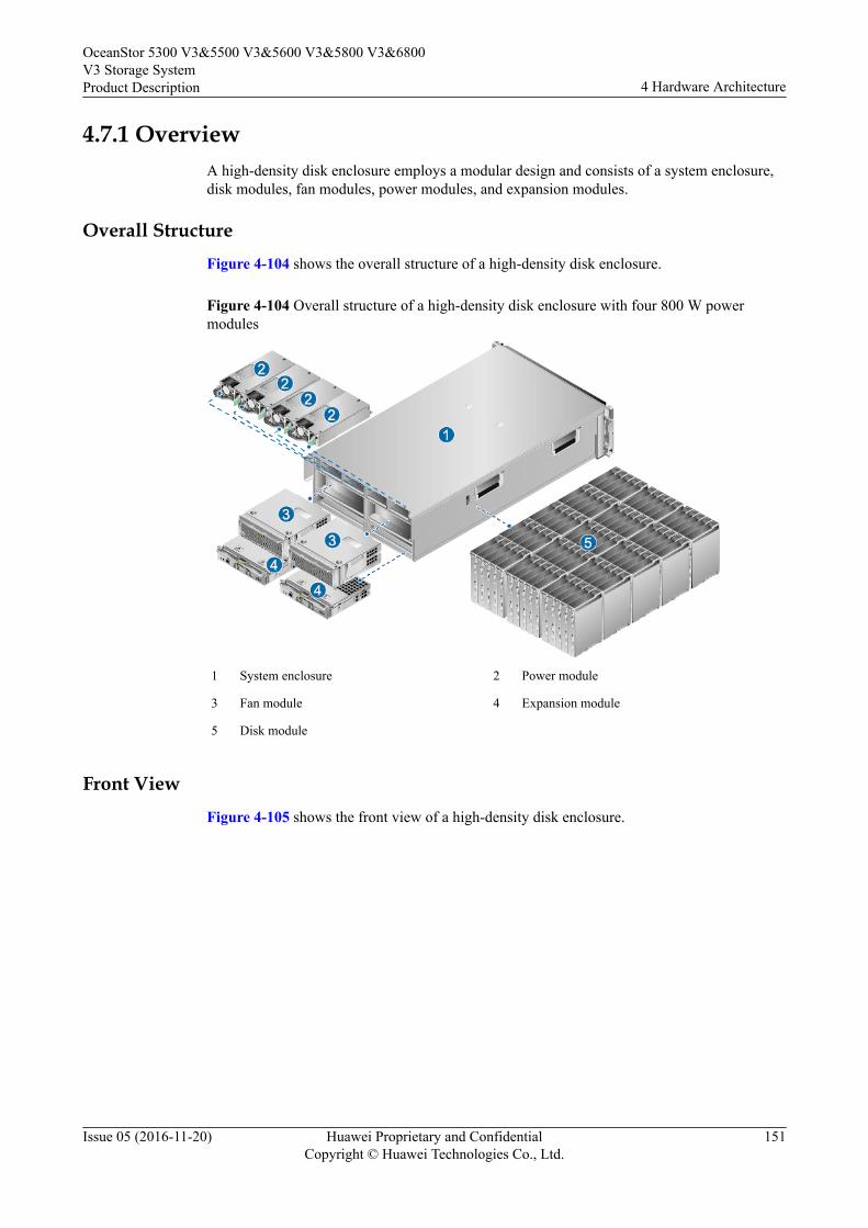
4.7.1 OverviewA high-density disk enclosure employs a modular design and consists of a system enclosure,disk modules, fan modules, power modules, and expansion modules.
Overall StructureFigure 4-104 shows the overall structure of a high-density disk enclosure.
Figure 4-104 Overall structure of a high-density disk enclosure with four 800 W powermodules
1 System enclosure 2 Power module
3 Fan module 4 Expansion module
5 Disk module
Front ViewFigure 4-105 shows the front view of a high-density disk enclosure.
OceanStor 5300 V3&5500 V3&5600 V3&5800 V3&6800V3 Storage SystemProduct Description 4 Hardware Architecture
Issue 05 (2016-11-20) Huawei Proprietary and ConfidentialCopyright © Huawei Technologies Co., Ltd.
151
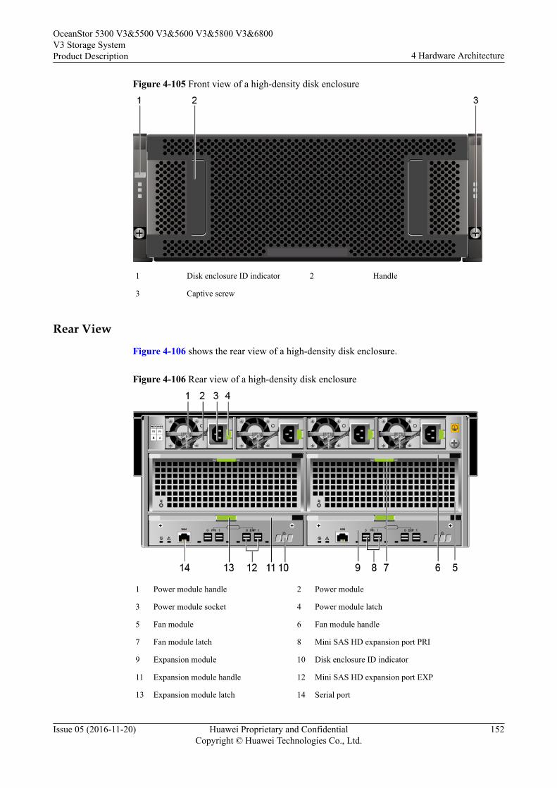
Figure 4-105 Front view of a high-density disk enclosure
1 Disk enclosure ID indicator 2 Handle
3 Captive screw
Rear View
Figure 4-106 shows the rear view of a high-density disk enclosure.
Figure 4-106 Rear view of a high-density disk enclosure
1 Power module handle 2 Power module
3 Power module socket 4 Power module latch
5 Fan module 6 Fan module handle
7 Fan module latch 8 Mini SAS HD expansion port PRI
9 Expansion module 10 Disk enclosure ID indicator
11 Expansion module handle 12 Mini SAS HD expansion port EXP
13 Expansion module latch 14 Serial port
OceanStor 5300 V3&5500 V3&5600 V3&5800 V3&6800V3 Storage SystemProduct Description 4 Hardware Architecture
Issue 05 (2016-11-20) Huawei Proprietary and ConfidentialCopyright © Huawei Technologies Co., Ltd.
152
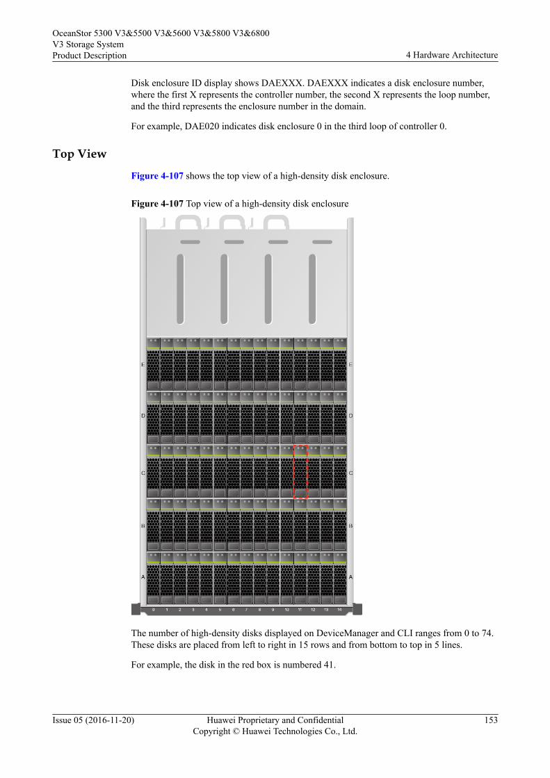
Disk enclosure ID display shows DAEXXX. DAEXXX indicates a disk enclosure number,where the first X represents the controller number, the second X represents the loop number,and the third represents the enclosure number in the domain.
For example, DAE020 indicates disk enclosure 0 in the third loop of controller 0.
Top View
Figure 4-107 shows the top view of a high-density disk enclosure.
Figure 4-107 Top view of a high-density disk enclosure
The number of high-density disks displayed on DeviceManager and CLI ranges from 0 to 74.These disks are placed from left to right in 15 rows and from bottom to top in 5 lines.
For example, the disk in the red box is numbered 41.
OceanStor 5300 V3&5500 V3&5600 V3&5800 V3&6800V3 Storage SystemProduct Description 4 Hardware Architecture
Issue 05 (2016-11-20) Huawei Proprietary and ConfidentialCopyright © Huawei Technologies Co., Ltd.
153
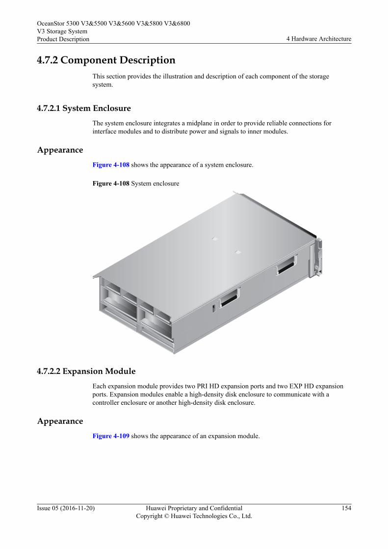
4.7.2 Component DescriptionThis section provides the illustration and description of each component of the storagesystem.
4.7.2.1 System EnclosureThe system enclosure integrates a midplane in order to provide reliable connections forinterface modules and to distribute power and signals to inner modules.
AppearanceFigure 4-108 shows the appearance of a system enclosure.
Figure 4-108 System enclosure
4.7.2.2 Expansion ModuleEach expansion module provides two PRI HD expansion ports and two EXP HD expansionports. Expansion modules enable a high-density disk enclosure to communicate with acontroller enclosure or another high-density disk enclosure.
AppearanceFigure 4-109 shows the appearance of an expansion module.
OceanStor 5300 V3&5500 V3&5600 V3&5800 V3&6800V3 Storage SystemProduct Description 4 Hardware Architecture
Issue 05 (2016-11-20) Huawei Proprietary and ConfidentialCopyright © Huawei Technologies Co., Ltd.
154
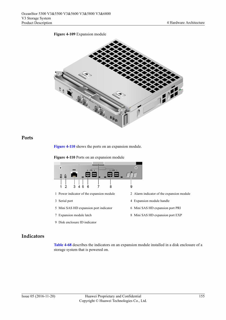
Figure 4-109 Expansion module
PortsFigure 4-110 shows the ports on an expansion module.
Figure 4-110 Ports on an expansion module
1 Power indicator of the expansion module 2 Alarm indicator of the expansion module
3 Serial port 4 Expansion module handle
5 Mini SAS HD expansion port indicator 6 Mini SAS HD expansion port PRI
7 Expansion module latch 8 Mini SAS HD expansion port EXP
9 Disk enclosure ID indicator
IndicatorsTable 4-68 describes the indicators on an expansion module installed in a disk enclosure of astorage system that is powered on.
OceanStor 5300 V3&5500 V3&5600 V3&5800 V3&6800V3 Storage SystemProduct Description 4 Hardware Architecture
Issue 05 (2016-11-20) Huawei Proprietary and ConfidentialCopyright © Huawei Technologies Co., Ltd.
155
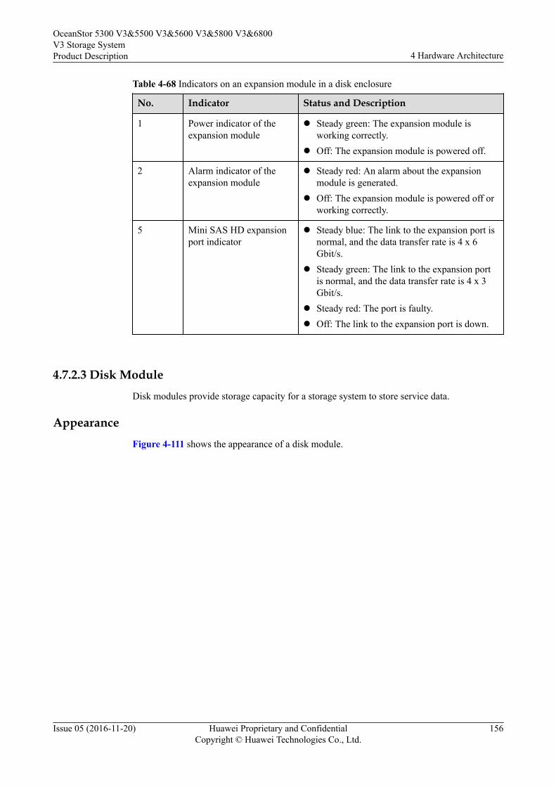
Table 4-68 Indicators on an expansion module in a disk enclosure
No. Indicator Status and Description
1 Power indicator of theexpansion module
l Steady green: The expansion module isworking correctly.
l Off: The expansion module is powered off.
2 Alarm indicator of theexpansion module
l Steady red: An alarm about the expansionmodule is generated.
l Off: The expansion module is powered off orworking correctly.
5 Mini SAS HD expansionport indicator
l Steady blue: The link to the expansion port isnormal, and the data transfer rate is 4 x 6Gbit/s.
l Steady green: The link to the expansion portis normal, and the data transfer rate is 4 x 3Gbit/s.
l Steady red: The port is faulty.l Off: The link to the expansion port is down.
4.7.2.3 Disk ModuleDisk modules provide storage capacity for a storage system to store service data.
AppearanceFigure 4-111 shows the appearance of a disk module.
OceanStor 5300 V3&5500 V3&5600 V3&5800 V3&6800V3 Storage SystemProduct Description 4 Hardware Architecture
Issue 05 (2016-11-20) Huawei Proprietary and ConfidentialCopyright © Huawei Technologies Co., Ltd.
156
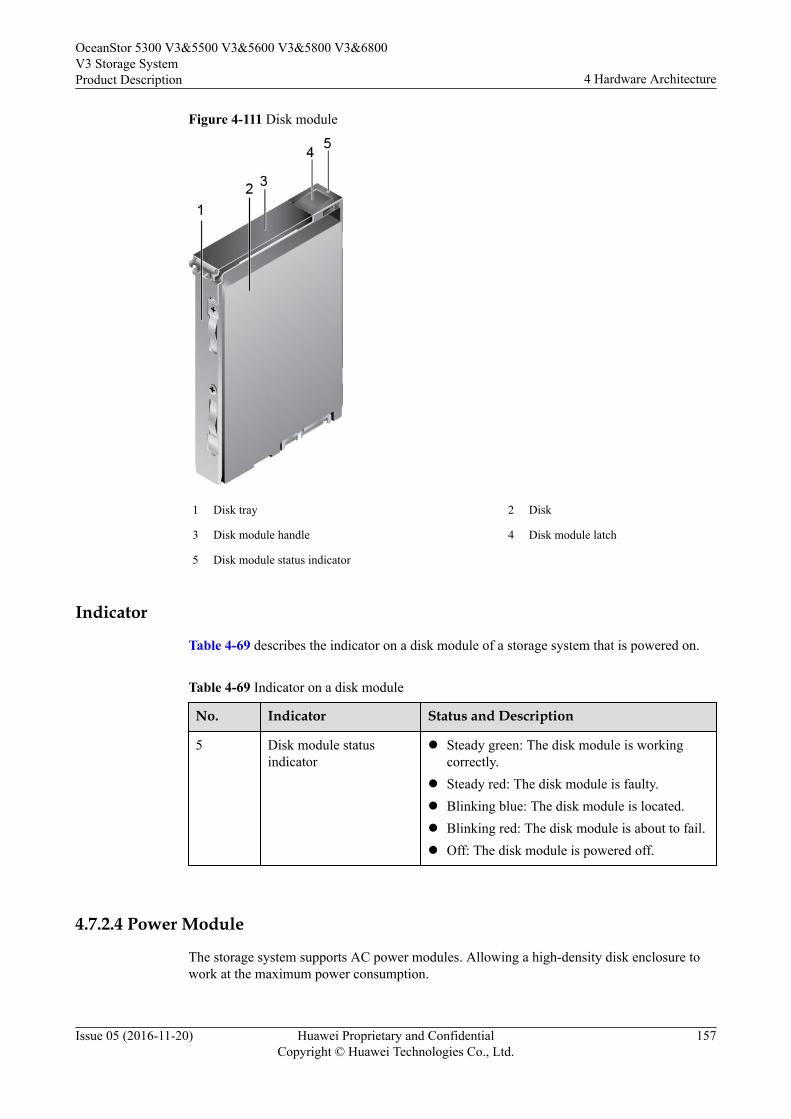
Figure 4-111 Disk module
1 Disk tray 2 Disk
3 Disk module handle 4 Disk module latch
5 Disk module status indicator
Indicator
Table 4-69 describes the indicator on a disk module of a storage system that is powered on.
Table 4-69 Indicator on a disk module
No. Indicator Status and Description
5 Disk module statusindicator
l Steady green: The disk module is workingcorrectly.
l Steady red: The disk module is faulty.l Blinking blue: The disk module is located.l Blinking red: The disk module is about to fail.l Off: The disk module is powered off.
4.7.2.4 Power Module
The storage system supports AC power modules. Allowing a high-density disk enclosure towork at the maximum power consumption.
OceanStor 5300 V3&5500 V3&5600 V3&5800 V3&6800V3 Storage SystemProduct Description 4 Hardware Architecture
Issue 05 (2016-11-20) Huawei Proprietary and ConfidentialCopyright © Huawei Technologies Co., Ltd.
157
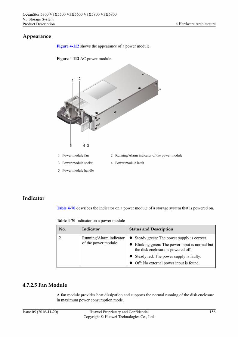
Appearance
Figure 4-112 shows the appearance of a power module.
Figure 4-112 AC power module
1 Power module fan 2 Running/Alarm indicator of the power module
3 Power module socket 4 Power module latch
5 Power module handle
Indicator
Table 4-70 describes the indicator on a power module of a storage system that is powered on.
Table 4-70 Indicator on a power module
No. Indicator Status and Description
2 Running/Alarm indicatorof the power module
l Steady green: The power supply is correct.l Blinking green: The power input is normal but
the disk enclosure is powered off.l Steady red: The power supply is faulty.l Off: No external power input is found.
4.7.2.5 Fan Module
A fan module provides heat dissipation and supports the normal running of the disk enclosurein maximum power consumption mode.
OceanStor 5300 V3&5500 V3&5600 V3&5800 V3&6800V3 Storage SystemProduct Description 4 Hardware Architecture
Issue 05 (2016-11-20) Huawei Proprietary and ConfidentialCopyright © Huawei Technologies Co., Ltd.
158
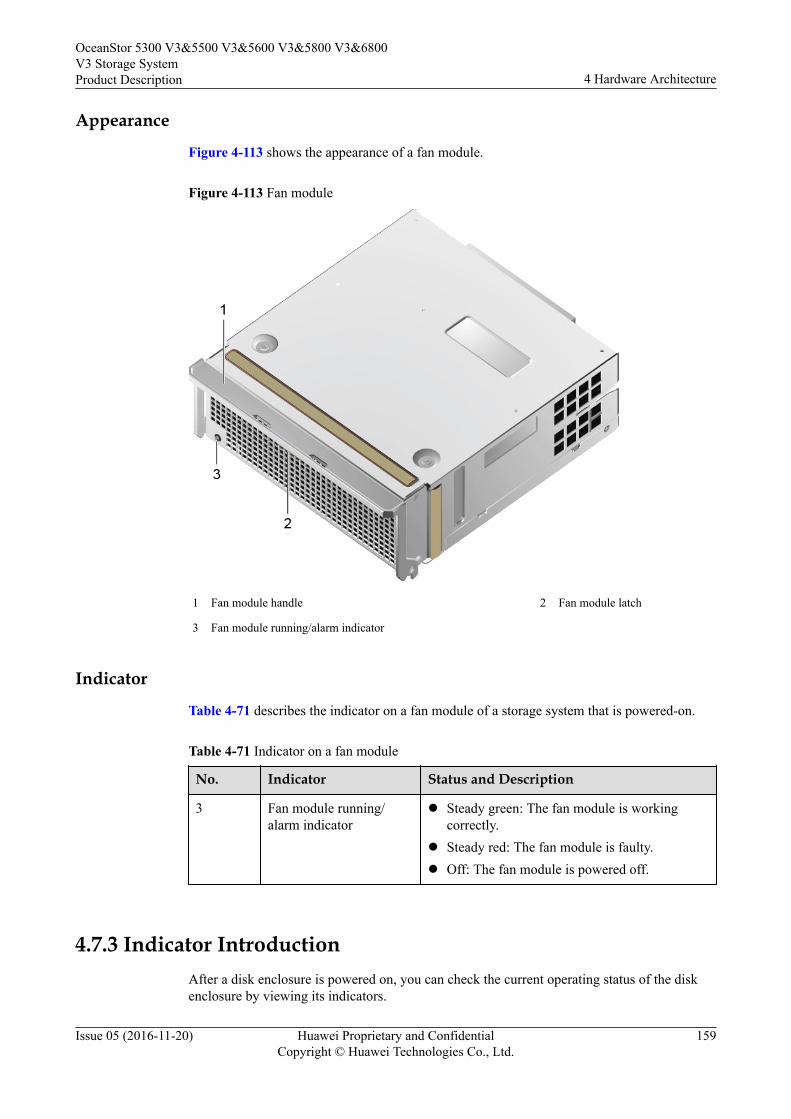
Appearance
Figure 4-113 shows the appearance of a fan module.
Figure 4-113 Fan module
1 Fan module handle 2 Fan module latch
3 Fan module running/alarm indicator
Indicator
Table 4-71 describes the indicator on a fan module of a storage system that is powered-on.
Table 4-71 Indicator on a fan module
No. Indicator Status and Description
3 Fan module running/alarm indicator
l Steady green: The fan module is workingcorrectly.
l Steady red: The fan module is faulty.l Off: The fan module is powered off.
4.7.3 Indicator IntroductionAfter a disk enclosure is powered on, you can check the current operating status of the diskenclosure by viewing its indicators.
OceanStor 5300 V3&5500 V3&5600 V3&5800 V3&6800V3 Storage SystemProduct Description 4 Hardware Architecture
Issue 05 (2016-11-20) Huawei Proprietary and ConfidentialCopyright © Huawei Technologies Co., Ltd.
159
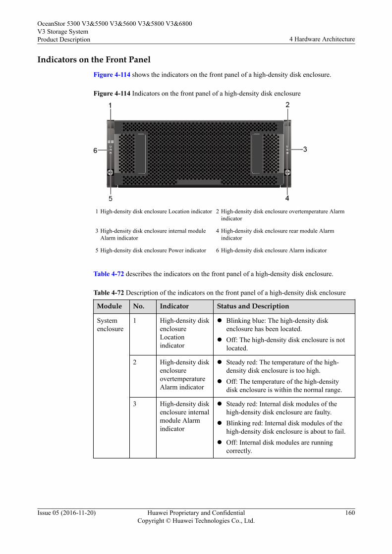
Indicators on the Front PanelFigure 4-114 shows the indicators on the front panel of a high-density disk enclosure.
Figure 4-114 Indicators on the front panel of a high-density disk enclosure
1 High-density disk enclosure Location indicator 2 High-density disk enclosure overtemperature Alarmindicator
3 High-density disk enclosure internal moduleAlarm indicator
4 High-density disk enclosure rear module Alarmindicator
5 High-density disk enclosure Power indicator 6 High-density disk enclosure Alarm indicator
Table 4-72 describes the indicators on the front panel of a high-density disk enclosure.
Table 4-72 Description of the indicators on the front panel of a high-density disk enclosure
Module No. Indicator Status and Description
Systemenclosure
1 High-density diskenclosureLocationindicator
l Blinking blue: The high-density diskenclosure has been located.
l Off: The high-density disk enclosure is notlocated.
2 High-density diskenclosureovertemperatureAlarm indicator
l Steady red: The temperature of the high-density disk enclosure is too high.
l Off: The temperature of the high-densitydisk enclosure is within the normal range.
3 High-density diskenclosure internalmodule Alarmindicator
l Steady red: Internal disk modules of thehigh-density disk enclosure are faulty.
l Blinking red: Internal disk modules of thehigh-density disk enclosure is about to fail.
l Off: Internal disk modules are runningcorrectly.
OceanStor 5300 V3&5500 V3&5600 V3&5800 V3&6800V3 Storage SystemProduct Description 4 Hardware Architecture
Issue 05 (2016-11-20) Huawei Proprietary and ConfidentialCopyright © Huawei Technologies Co., Ltd.
160
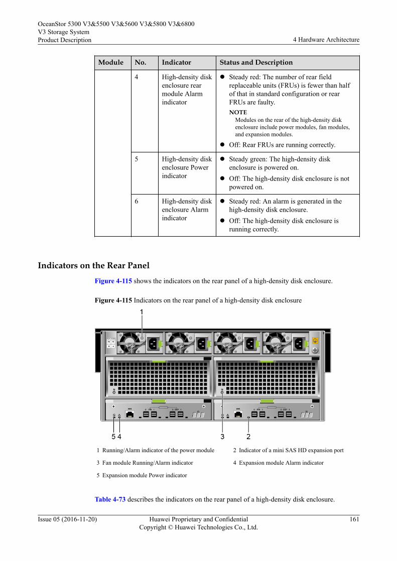
Module No. Indicator Status and Description
4 High-density diskenclosure rearmodule Alarmindicator
l Steady red: The number of rear fieldreplaceable units (FRUs) is fewer than halfof that in standard configuration or rearFRUs are faulty.NOTE
Modules on the rear of the high-density diskenclosure include power modules, fan modules,and expansion modules.
l Off: Rear FRUs are running correctly.
5 High-density diskenclosure Powerindicator
l Steady green: The high-density diskenclosure is powered on.
l Off: The high-density disk enclosure is notpowered on.
6 High-density diskenclosure Alarmindicator
l Steady red: An alarm is generated in thehigh-density disk enclosure.
l Off: The high-density disk enclosure isrunning correctly.
Indicators on the Rear Panel
Figure 4-115 shows the indicators on the rear panel of a high-density disk enclosure.
Figure 4-115 Indicators on the rear panel of a high-density disk enclosure
1 Running/Alarm indicator of the power module 2 Indicator of a mini SAS HD expansion port
3 Fan module Running/Alarm indicator 4 Expansion module Alarm indicator
5 Expansion module Power indicator
Table 4-73 describes the indicators on the rear panel of a high-density disk enclosure.
OceanStor 5300 V3&5500 V3&5600 V3&5800 V3&6800V3 Storage SystemProduct Description 4 Hardware Architecture
Issue 05 (2016-11-20) Huawei Proprietary and ConfidentialCopyright © Huawei Technologies Co., Ltd.
161
Table 4-73 Description of the indicators on the front panel of a high-density disk enclosure
Module No. Indicator Status and Description
Powermodule
1 Running/Alarm indicator ofthe power module
l Steady green: The power supplyis correct.
l Blinking green: The power inputis normal but the disk enclosureis powered off.
l Steady red: The power supply isfaulty.
l Off: No external power input isfound.
Expansionmodule
2 Indicator of a mini SAS HDexpansion port
l Steady blue: The link is up andthe data transfer rate is 4 x 6Gbit/s.
l Steady green: The link is up andthe data transfer rate is 4 x 3Gbit/s.
l Steady red: The expansion port isfaulty.
l Off: The link is down.
Fanmodule
3 Fan module Running/Alarmindicator
l Steady green: The fan module isrunning correctly.
l Steady red: The fan module isfaulty.
l Off: The fan module is notpowered on.
Expansionmodule
4 Expansion module Alarmindicator
l Steady red: The expansionmodule is faulty.
l Off: The expansion module is notpowered or is running correctly.
5 Expansion module Powerindicator
l Steady green: The expansionmodule is running correctly.
l Off: The expansion module is notpowered on.
4.8 (optional) Data SwitchWhen IP Scale-out is implemented for a storage system and a switch-connection network isused, CE6850-48S4Q-EI data switches are required.
When a storage system uses a switch-connection network for capacity expansion, only somefunctions of the switches are used. For more information about the switches, see theCloudEngine 7800&6800&5800 Product Documentation.
OceanStor 5300 V3&5500 V3&5600 V3&5800 V3&6800V3 Storage SystemProduct Description 4 Hardware Architecture
Issue 05 (2016-11-20) Huawei Proprietary and ConfidentialCopyright © Huawei Technologies Co., Ltd.
162
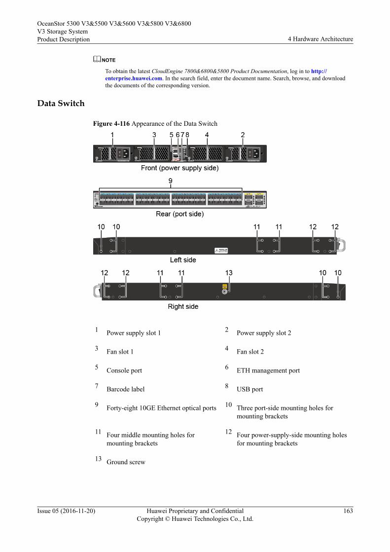
NOTE
To obtain the latest CloudEngine 7800&6800&5800 Product Documentation, log in to http://enterprise.huawei.com. In the search field, enter the document name. Search, browse, and downloadthe documents of the corresponding version.
Data Switch
Figure 4-116 Appearance of the Data Switch
1 Power supply slot 1 2 Power supply slot 2
3 Fan slot 1 4 Fan slot 2
5 Console port 6 ETH management port
7 Barcode label 8 USB port
9 Forty-eight 10GE Ethernet optical ports 10 Three port-side mounting holes formounting brackets
11 Four middle mounting holes formounting brackets
12 Four power-supply-side mounting holesfor mounting brackets
13 Ground screw
OceanStor 5300 V3&5500 V3&5600 V3&5800 V3&6800V3 Storage SystemProduct Description 4 Hardware Architecture
Issue 05 (2016-11-20) Huawei Proprietary and ConfidentialCopyright © Huawei Technologies Co., Ltd.
163
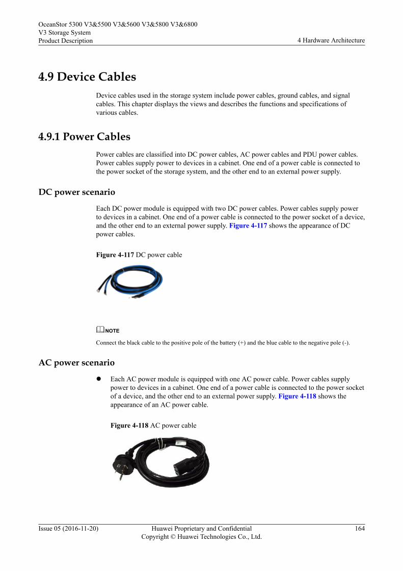
4.9 Device CablesDevice cables used in the storage system include power cables, ground cables, and signalcables. This chapter displays the views and describes the functions and specifications ofvarious cables.
4.9.1 Power CablesPower cables are classified into DC power cables, AC power cables and PDU power cables.Power cables supply power to devices in a cabinet. One end of a power cable is connected tothe power socket of the storage system, and the other end to an external power supply.
DC power scenario
Each DC power module is equipped with two DC power cables. Power cables supply powerto devices in a cabinet. One end of a power cable is connected to the power socket of a device,and the other end to an external power supply. Figure 4-117 shows the appearance of DCpower cables.
Figure 4-117 DC power cable
NOTE
Connect the black cable to the positive pole of the battery (+) and the blue cable to the negative pole (-).
AC power scenario
l Each AC power module is equipped with one AC power cable. Power cables supplypower to devices in a cabinet. One end of a power cable is connected to the power socketof a device, and the other end to an external power supply. Figure 4-118 shows theappearance of an AC power cable.
Figure 4-118 AC power cable
OceanStor 5300 V3&5500 V3&5600 V3&5800 V3&6800V3 Storage SystemProduct Description 4 Hardware Architecture
Issue 05 (2016-11-20) Huawei Proprietary and ConfidentialCopyright © Huawei Technologies Co., Ltd.
164
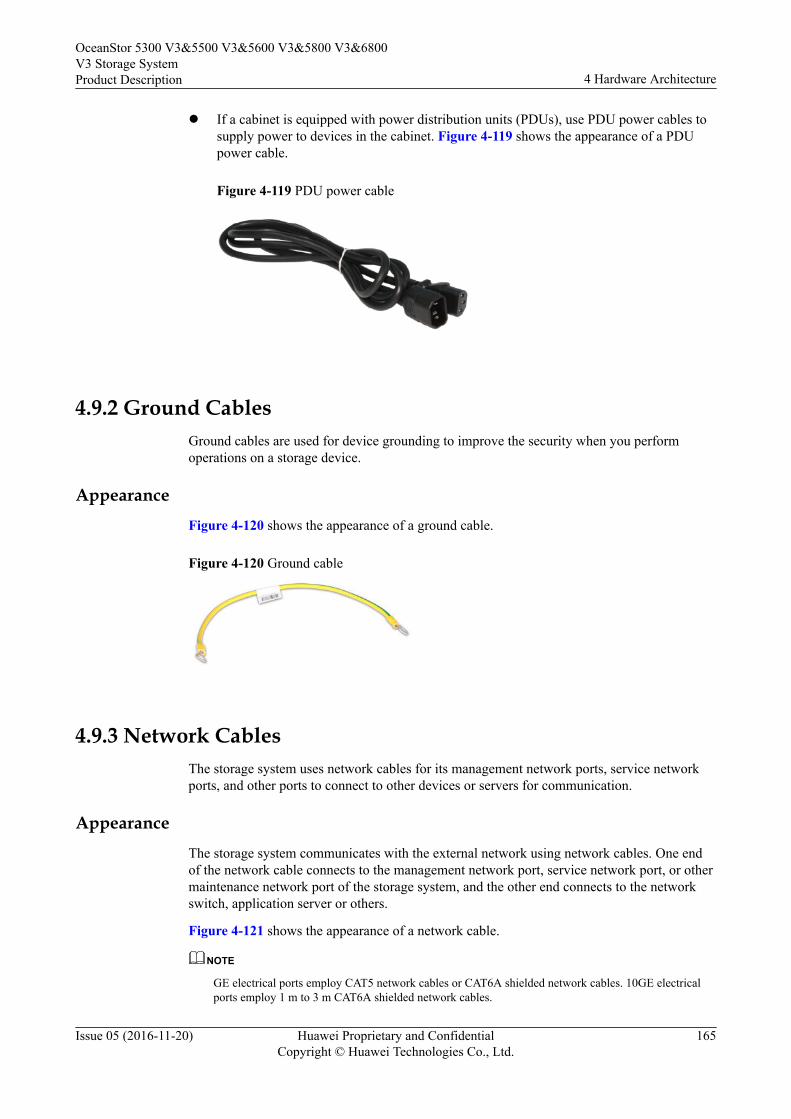
l If a cabinet is equipped with power distribution units (PDUs), use PDU power cables tosupply power to devices in the cabinet. Figure 4-119 shows the appearance of a PDUpower cable.
Figure 4-119 PDU power cable
4.9.2 Ground CablesGround cables are used for device grounding to improve the security when you performoperations on a storage device.
AppearanceFigure 4-120 shows the appearance of a ground cable.
Figure 4-120 Ground cable
4.9.3 Network CablesThe storage system uses network cables for its management network ports, service networkports, and other ports to connect to other devices or servers for communication.
AppearanceThe storage system communicates with the external network using network cables. One endof the network cable connects to the management network port, service network port, or othermaintenance network port of the storage system, and the other end connects to the networkswitch, application server or others.
Figure 4-121 shows the appearance of a network cable.
NOTE
GE electrical ports employ CAT5 network cables or CAT6A shielded network cables. 10GE electricalports employ 1 m to 3 m CAT6A shielded network cables.
OceanStor 5300 V3&5500 V3&5600 V3&5800 V3&6800V3 Storage SystemProduct Description 4 Hardware Architecture
Issue 05 (2016-11-20) Huawei Proprietary and ConfidentialCopyright © Huawei Technologies Co., Ltd.
165
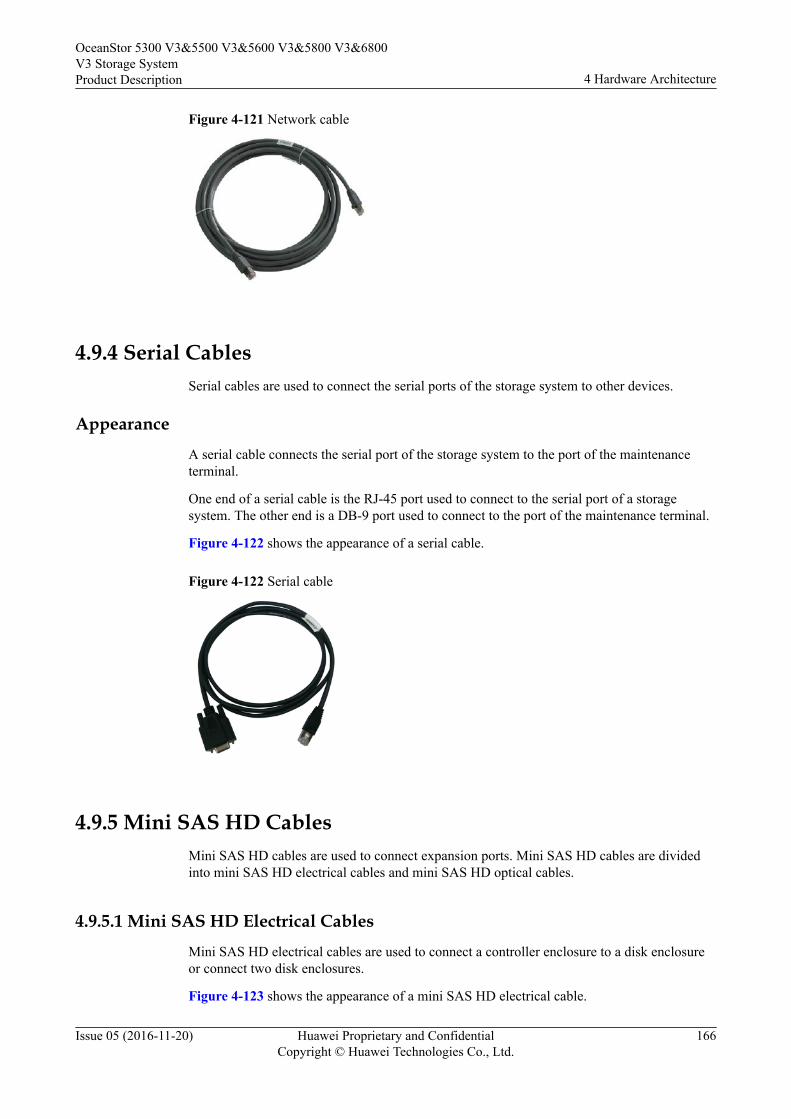
Figure 4-121 Network cable
4.9.4 Serial CablesSerial cables are used to connect the serial ports of the storage system to other devices.
Appearance
A serial cable connects the serial port of the storage system to the port of the maintenanceterminal.
One end of a serial cable is the RJ-45 port used to connect to the serial port of a storagesystem. The other end is a DB-9 port used to connect to the port of the maintenance terminal.
Figure 4-122 shows the appearance of a serial cable.
Figure 4-122 Serial cable
4.9.5 Mini SAS HD CablesMini SAS HD cables are used to connect expansion ports. Mini SAS HD cables are dividedinto mini SAS HD electrical cables and mini SAS HD optical cables.
4.9.5.1 Mini SAS HD Electrical Cables
Mini SAS HD electrical cables are used to connect a controller enclosure to a disk enclosureor connect two disk enclosures.
Figure 4-123 shows the appearance of a mini SAS HD electrical cable.
OceanStor 5300 V3&5500 V3&5600 V3&5800 V3&6800V3 Storage SystemProduct Description 4 Hardware Architecture
Issue 05 (2016-11-20) Huawei Proprietary and ConfidentialCopyright © Huawei Technologies Co., Ltd.
166
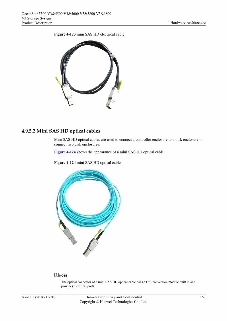
Figure 4-123 mini SAS HD electrical cable
4.9.5.2 Mini SAS HD optical cablesMini SAS HD optical cables are used to connect a controller enclosure to a disk enclosure orconnect two disk enclosures.
Figure 4-124 shows the appearance of a mini SAS HD optical cable.
Figure 4-124 mini SAS HD optical cable
NOTE
The optical connector of a mini SAS HD optical cable has an O/E conversion module built in andprovides electrical ports.
OceanStor 5300 V3&5500 V3&5600 V3&5800 V3&6800V3 Storage SystemProduct Description 4 Hardware Architecture
Issue 05 (2016-11-20) Huawei Proprietary and ConfidentialCopyright © Huawei Technologies Co., Ltd.
167
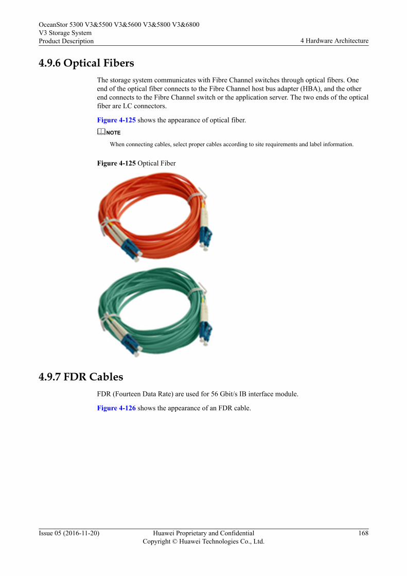
4.9.6 Optical FibersThe storage system communicates with Fibre Channel switches through optical fibers. Oneend of the optical fiber connects to the Fibre Channel host bus adapter (HBA), and the otherend connects to the Fibre Channel switch or the application server. The two ends of the opticalfiber are LC connectors.
Figure 4-125 shows the appearance of optical fiber.
NOTE
When connecting cables, select proper cables according to site requirements and label information.
Figure 4-125 Optical Fiber
4.9.7 FDR CablesFDR (Fourteen Data Rate) are used for 56 Gbit/s IB interface module.
Figure 4-126 shows the appearance of an FDR cable.
OceanStor 5300 V3&5500 V3&5600 V3&5800 V3&6800V3 Storage SystemProduct Description 4 Hardware Architecture
Issue 05 (2016-11-20) Huawei Proprietary and ConfidentialCopyright © Huawei Technologies Co., Ltd.
168
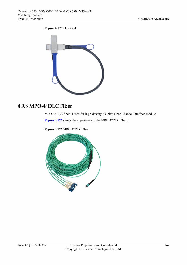
Figure 4-126 FDR cable
4.9.8 MPO-4*DLC FiberMPO-4*DLC fiber is used for high-density 8 Gbit/s Fibre Channel interface module.
Figure 4-127 shows the appearance of the MPO-4*DLC fiber.
Figure 4-127 MPO-4*DLC fiber
OceanStor 5300 V3&5500 V3&5600 V3&5800 V3&6800V3 Storage SystemProduct Description 4 Hardware Architecture
Issue 05 (2016-11-20) Huawei Proprietary and ConfidentialCopyright © Huawei Technologies Co., Ltd.
169
5 Software Architecture
Storage system software manages the storage devices and the data stored, and assistsapplication servers in data operations.
The software suite provided by OceanStor 5300 V3/5500 V3/5600 V3/5800 V3/6800 V3storage system consists of software running on a storage system, software running on amaintenance terminal, and software running on an application server. These three types ofsoftware work jointly to deliver storage, backup, and disaster recovery services in a smart,efficient, and cost-effective manner.
Figure 5-1 shows the storage system software architecture.
OceanStor 5300 V3&5500 V3&5600 V3&5800 V3&6800V3 Storage SystemProduct Description 5 Software Architecture
Issue 05 (2016-11-20) Huawei Proprietary and ConfidentialCopyright © Huawei Technologies Co., Ltd.
170
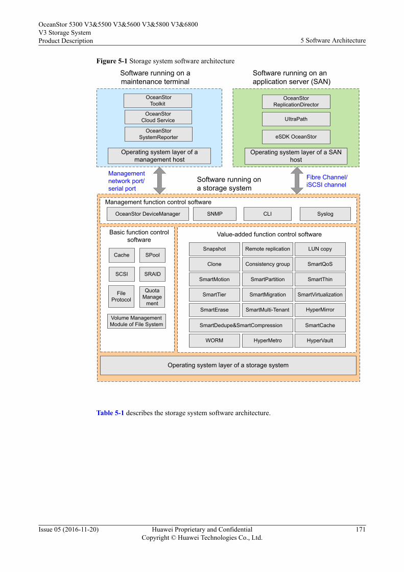
Figure 5-1 Storage system software architecture
Software running on a maintenance terminal
Software running on a storage system
Operating system layer of a storage system
Value-added function control softwareBasic function control software
Software running on an application server (SAN)
Management network port/serial port
Fibre Channel/iSCSI channel
Cache
SCSI
Operating system layer of a management host
Operating system layer of a SAN host
SRAID
SPool
OceanStorToolkit
OceanStorSystemReporter
OceanStorCloud Service
OceanStorReplicationDirector
UItraPath
eSDK OceanStor
Snapshot
SmartThin
Remote replication
SmartQoS
LUN copy
SmartTier
Clone Consistency group
SmartMotion SmartPartition
SmartErase
SmartMigration SmartVirtualization
SmartMulti-Tenant HyperMirror
File Protocol
Quota Manage
ment
Volume Management Module of File System SmartDedupe&SmartCompression
Management function control software
OceanStor DeviceManager SNMP CLI Syslog
SmartCache
WORM HyperMetro HyperVault
Table 5-1 describes the storage system software architecture.
OceanStor 5300 V3&5500 V3&5600 V3&5800 V3&6800V3 Storage SystemProduct Description 5 Software Architecture
Issue 05 (2016-11-20) Huawei Proprietary and ConfidentialCopyright © Huawei Technologies Co., Ltd.
171
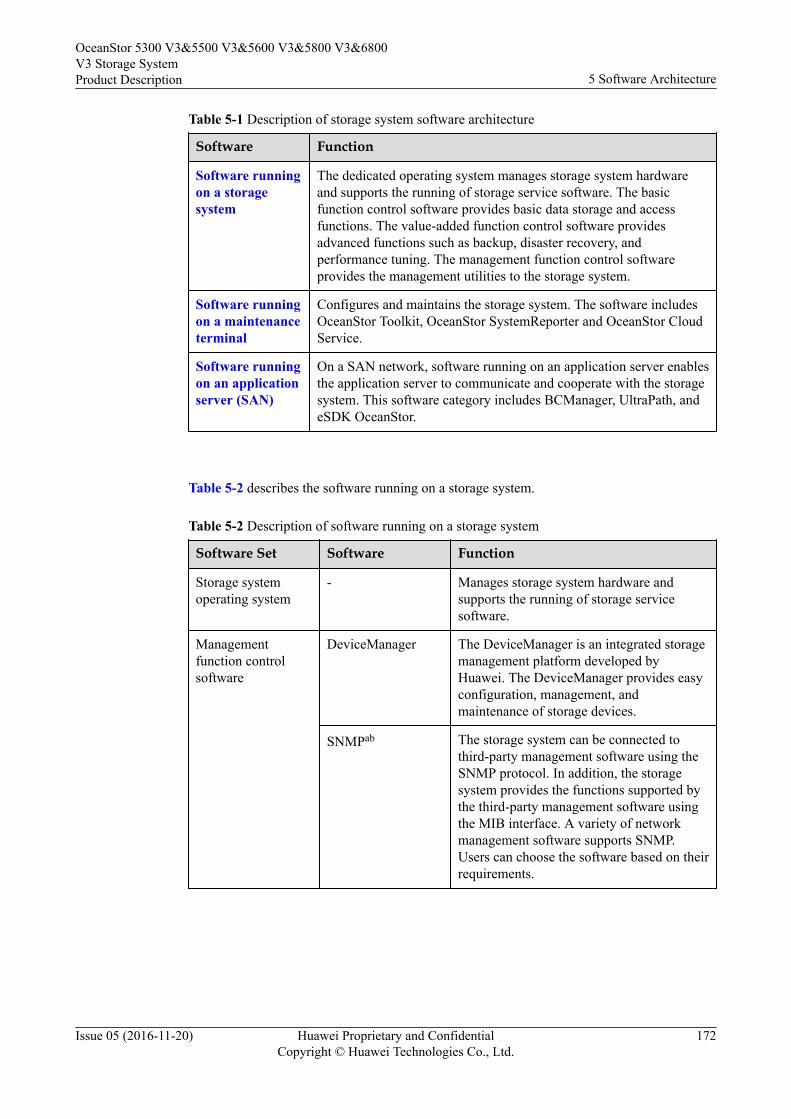
Table 5-1 Description of storage system software architecture
Software Function
Software runningon a storagesystem
The dedicated operating system manages storage system hardwareand supports the running of storage service software. The basicfunction control software provides basic data storage and accessfunctions. The value-added function control software providesadvanced functions such as backup, disaster recovery, andperformance tuning. The management function control softwareprovides the management utilities to the storage system.
Software runningon a maintenanceterminal
Configures and maintains the storage system. The software includesOceanStor Toolkit, OceanStor SystemReporter and OceanStor CloudService.
Software runningon an applicationserver (SAN)
On a SAN network, software running on an application server enablesthe application server to communicate and cooperate with the storagesystem. This software category includes BCManager, UltraPath, andeSDK OceanStor.
Table 5-2 describes the software running on a storage system.
Table 5-2 Description of software running on a storage system
Software Set Software Function
Storage systemoperating system
- Manages storage system hardware andsupports the running of storage servicesoftware.
Managementfunction controlsoftware
DeviceManager The DeviceManager is an integrated storagemanagement platform developed byHuawei. The DeviceManager provides easyconfiguration, management, andmaintenance of storage devices.
SNMPab The storage system can be connected tothird-party management software using theSNMP protocol. In addition, the storagesystem provides the functions supported bythe third-party management software usingthe MIB interface. A variety of networkmanagement software supports SNMP.Users can choose the software based on theirrequirements.
OceanStor 5300 V3&5500 V3&5600 V3&5800 V3&6800V3 Storage SystemProduct Description 5 Software Architecture
Issue 05 (2016-11-20) Huawei Proprietary and ConfidentialCopyright © Huawei Technologies Co., Ltd.
172
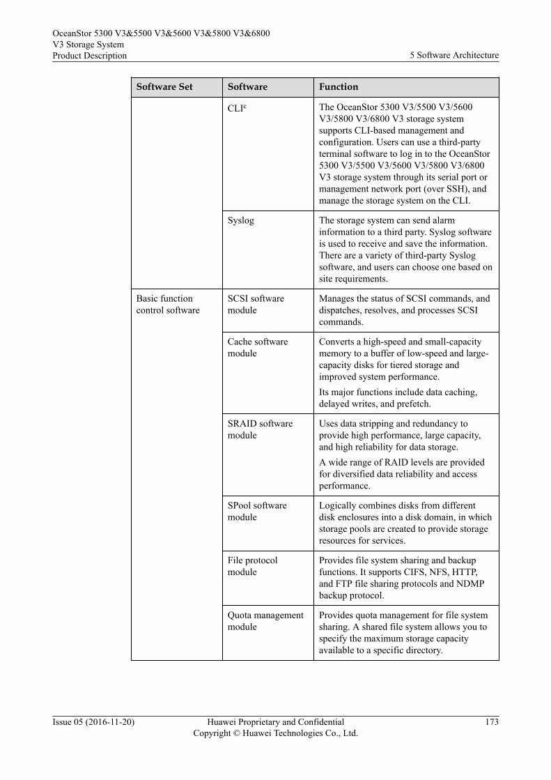
Software Set Software Function
CLIc The OceanStor 5300 V3/5500 V3/5600V3/5800 V3/6800 V3 storage systemsupports CLI-based management andconfiguration. Users can use a third-partyterminal software to log in to the OceanStor5300 V3/5500 V3/5600 V3/5800 V3/6800V3 storage system through its serial port ormanagement network port (over SSH), andmanage the storage system on the CLI.
Syslog The storage system can send alarminformation to a third party. Syslog softwareis used to receive and save the information.There are a variety of third-party Syslogsoftware, and users can choose one based onsite requirements.
Basic functioncontrol software
SCSI softwaremodule
Manages the status of SCSI commands, anddispatches, resolves, and processes SCSIcommands.
Cache softwaremodule
Converts a high-speed and small-capacitymemory to a buffer of low-speed and large-capacity disks for tiered storage andimproved system performance.Its major functions include data caching,delayed writes, and prefetch.
SRAID softwaremodule
Uses data stripping and redundancy toprovide high performance, large capacity,and high reliability for data storage.A wide range of RAID levels are providedfor diversified data reliability and accessperformance.
SPool softwaremodule
Logically combines disks from differentdisk enclosures into a disk domain, in whichstorage pools are created to provide storageresources for services.
File protocolmodule
Provides file system sharing and backupfunctions. It supports CIFS, NFS, HTTP,and FTP file sharing protocols and NDMPbackup protocol.
Quota managementmodule
Provides quota management for file systemsharing. A shared file system allows you tospecify the maximum storage capacityavailable to a specific directory.
OceanStor 5300 V3&5500 V3&5600 V3&5800 V3&6800V3 Storage SystemProduct Description 5 Software Architecture
Issue 05 (2016-11-20) Huawei Proprietary and ConfidentialCopyright © Huawei Technologies Co., Ltd.
173
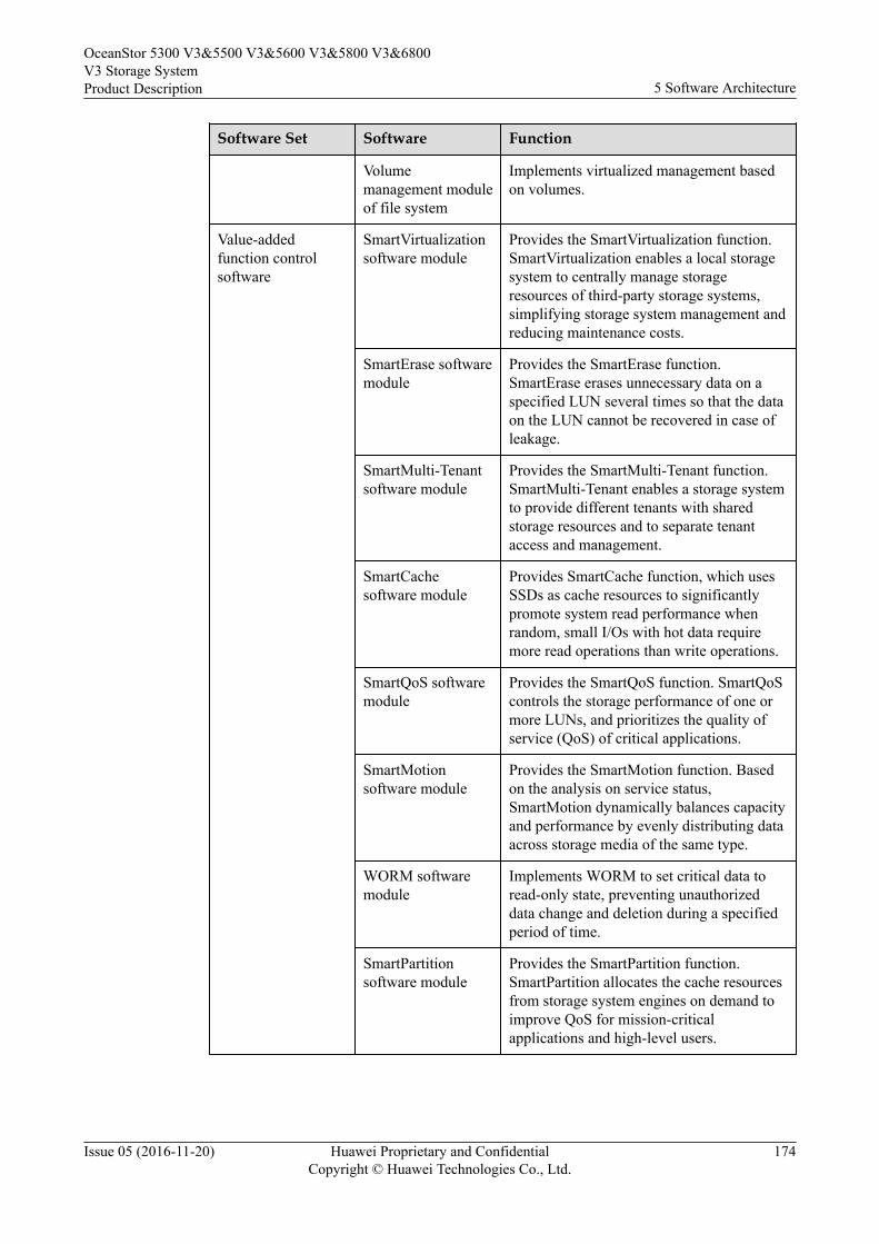
Software Set Software Function
Volumemanagement moduleof file system
Implements virtualized management basedon volumes.
Value-addedfunction controlsoftware
SmartVirtualizationsoftware module
Provides the SmartVirtualization function.SmartVirtualization enables a local storagesystem to centrally manage storageresources of third-party storage systems,simplifying storage system management andreducing maintenance costs.
SmartErase softwaremodule
Provides the SmartErase function.SmartErase erases unnecessary data on aspecified LUN several times so that the dataon the LUN cannot be recovered in case ofleakage.
SmartMulti-Tenantsoftware module
Provides the SmartMulti-Tenant function.SmartMulti-Tenant enables a storage systemto provide different tenants with sharedstorage resources and to separate tenantaccess and management.
SmartCachesoftware module
Provides SmartCache function, which usesSSDs as cache resources to significantlypromote system read performance whenrandom, small I/Os with hot data requiremore read operations than write operations.
SmartQoS softwaremodule
Provides the SmartQoS function. SmartQoScontrols the storage performance of one ormore LUNs, and prioritizes the quality ofservice (QoS) of critical applications.
SmartMotionsoftware module
Provides the SmartMotion function. Basedon the analysis on service status,SmartMotion dynamically balances capacityand performance by evenly distributing dataacross storage media of the same type.
WORM softwaremodule
Implements WORM to set critical data toread-only state, preventing unauthorizeddata change and deletion during a specifiedperiod of time.
SmartPartitionsoftware module
Provides the SmartPartition function.SmartPartition allocates the cache resourcesfrom storage system engines on demand toimprove QoS for mission-criticalapplications and high-level users.
OceanStor 5300 V3&5500 V3&5600 V3&5800 V3&6800V3 Storage SystemProduct Description 5 Software Architecture
Issue 05 (2016-11-20) Huawei Proprietary and ConfidentialCopyright © Huawei Technologies Co., Ltd.
174
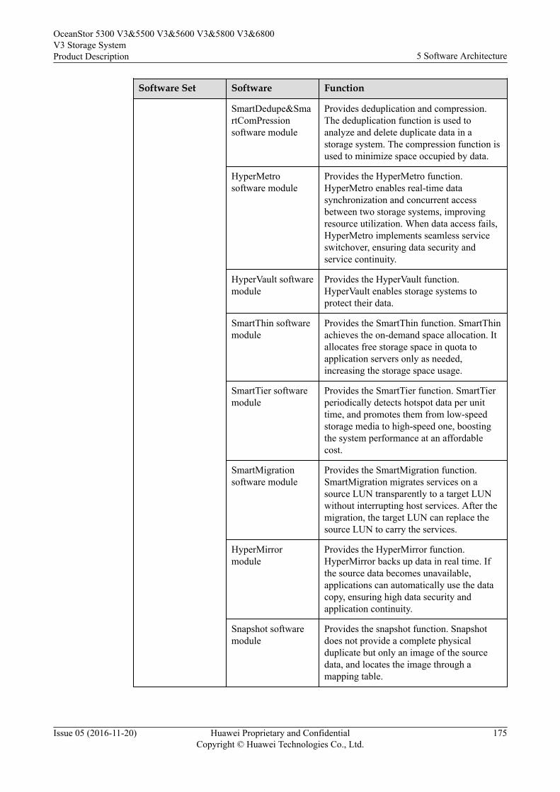
Software Set Software Function
SmartDedupe&SmartComPressionsoftware module
Provides deduplication and compression.The deduplication function is used toanalyze and delete duplicate data in astorage system. The compression function isused to minimize space occupied by data.
HyperMetrosoftware module
Provides the HyperMetro function.HyperMetro enables real-time datasynchronization and concurrent accessbetween two storage systems, improvingresource utilization. When data access fails,HyperMetro implements seamless serviceswitchover, ensuring data security andservice continuity.
HyperVault softwaremodule
Provides the HyperVault function.HyperVault enables storage systems toprotect their data.
SmartThin softwaremodule
Provides the SmartThin function. SmartThinachieves the on-demand space allocation. Itallocates free storage space in quota toapplication servers only as needed,increasing the storage space usage.
SmartTier softwaremodule
Provides the SmartTier function. SmartTierperiodically detects hotspot data per unittime, and promotes them from low-speedstorage media to high-speed one, boostingthe system performance at an affordablecost.
SmartMigrationsoftware module
Provides the SmartMigration function.SmartMigration migrates services on asource LUN transparently to a target LUNwithout interrupting host services. After themigration, the target LUN can replace thesource LUN to carry the services.
HyperMirrormodule
Provides the HyperMirror function.HyperMirror backs up data in real time. Ifthe source data becomes unavailable,applications can automatically use the datacopy, ensuring high data security andapplication continuity.
Snapshot softwaremodule
Provides the snapshot function. Snapshotdoes not provide a complete physicalduplicate but only an image of the sourcedata, and locates the image through amapping table.
OceanStor 5300 V3&5500 V3&5600 V3&5800 V3&6800V3 Storage SystemProduct Description 5 Software Architecture
Issue 05 (2016-11-20) Huawei Proprietary and ConfidentialCopyright © Huawei Technologies Co., Ltd.
175
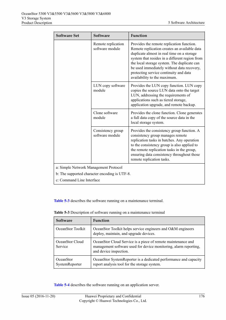
Software Set Software Function
Remote replicationsoftware module
Provides the remote replication function.Remote replication creates an available dataduplicate almost in real time on a storagesystem that resides in a different region fromthe local storage system. The duplicate canbe used immediately without data recovery,protecting service continuity and dataavailability to the maximum.
LUN copy softwaremodule
Provides the LUN copy function. LUN copycopies the source LUN data onto the targetLUN, addressing the requirements ofapplications such as tiered storage,application upgrade, and remote backup.
Clone softwaremodule
Provides the clone function. Clone generatesa full data copy of the source data in thelocal storage system.
Consistency groupsoftware module
Provides the consistency group function. Aconsistency group manages remotereplication tasks in batches. Any operationto the consistency group is also applied tothe remote replication tasks in the group,ensuring data consistency throughout thoseremote replication tasks.
a: Simple Network Management Protocolb: The supported character encoding is UTF-8.c: Command Line Interface
Table 5-3 describes the software running on a maintenance terminal.
Table 5-3 Description of software running on a maintenance terminal
Software Function
OceanStor Toolkit OceanStor Toolkit helps service engineers and O&M engineersdeploy, maintain, and upgrade devices.
OceanStor CloudService
OceanStor Cloud Service is a piece of remote maintenance andmanagement software used for device monitoring, alarm reporting,and device inspection.
OceanStorSystemReporter
OceanStor SystemReporter is a dedicated performance and capacityreport analysis tool for the storage system.
Table 5-4 describes the software running on an application server.
OceanStor 5300 V3&5500 V3&5600 V3&5800 V3&6800V3 Storage SystemProduct Description 5 Software Architecture
Issue 05 (2016-11-20) Huawei Proprietary and ConfidentialCopyright © Huawei Technologies Co., Ltd.
176
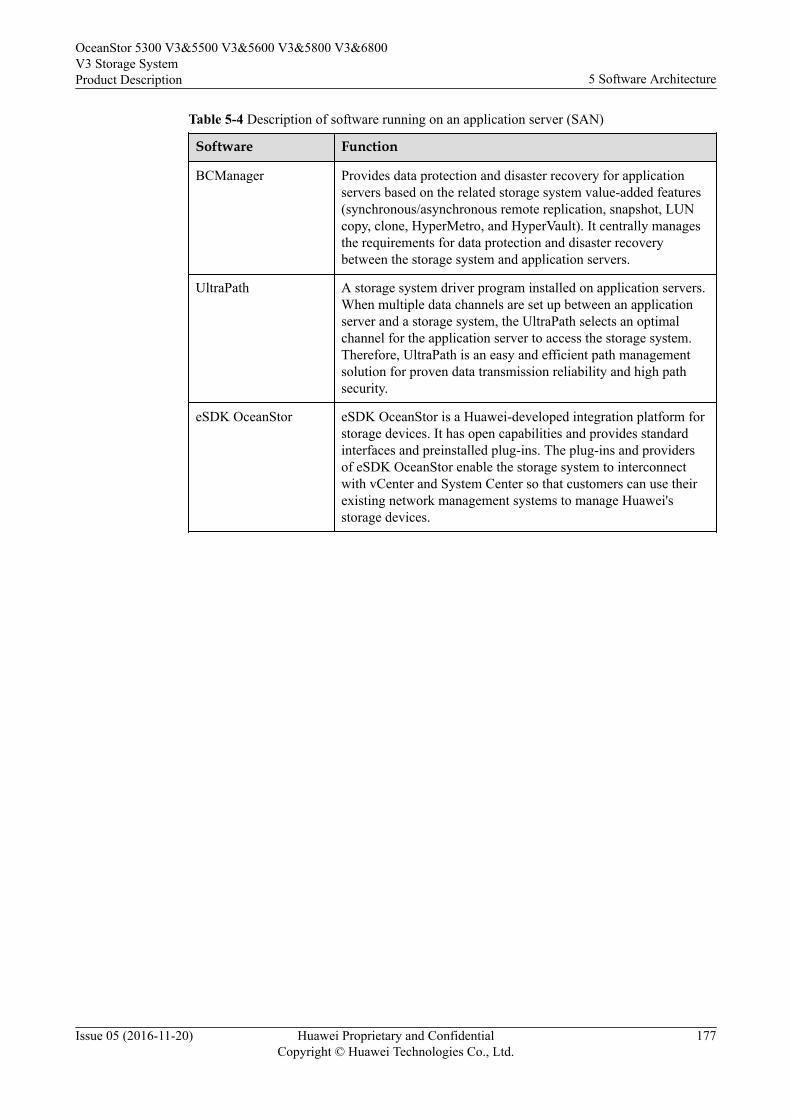
Table 5-4 Description of software running on an application server (SAN)
Software Function
BCManager Provides data protection and disaster recovery for applicationservers based on the related storage system value-added features(synchronous/asynchronous remote replication, snapshot, LUNcopy, clone, HyperMetro, and HyperVault). It centrally managesthe requirements for data protection and disaster recoverybetween the storage system and application servers.
UltraPath A storage system driver program installed on application servers.When multiple data channels are set up between an applicationserver and a storage system, the UltraPath selects an optimalchannel for the application server to access the storage system.Therefore, UltraPath is an easy and efficient path managementsolution for proven data transmission reliability and high pathsecurity.
eSDK OceanStor eSDK OceanStor is a Huawei-developed integration platform forstorage devices. It has open capabilities and provides standardinterfaces and preinstalled plug-ins. The plug-ins and providersof eSDK OceanStor enable the storage system to interconnectwith vCenter and System Center so that customers can use theirexisting network management systems to manage Huawei'sstorage devices.
OceanStor 5300 V3&5500 V3&5600 V3&5800 V3&6800V3 Storage SystemProduct Description 5 Software Architecture
Issue 05 (2016-11-20) Huawei Proprietary and ConfidentialCopyright © Huawei Technologies Co., Ltd.
177
6 Product Specifications
About This Chapter
This chapter describes the hardware specifications and software specifications of theOceanStor 5300 V3/5500 V3/5600 V3/5800 V3/6800 V3 storage system.
6.1 Hardware SpecificationsHardware specifications cover the hardware configuration, port specifications, diskspecifications, dimensions, weight, electrical specifications, and reliability specifications.
6.2 Software SpecificationsThe software specifications include the basic specifications, feature specifications,performance specifications, supported operating systems, and license control.
OceanStor 5300 V3&5500 V3&5600 V3&5800 V3&6800V3 Storage SystemProduct Description 6 Product Specifications
Issue 05 (2016-11-20) Huawei Proprietary and ConfidentialCopyright © Huawei Technologies Co., Ltd.
178
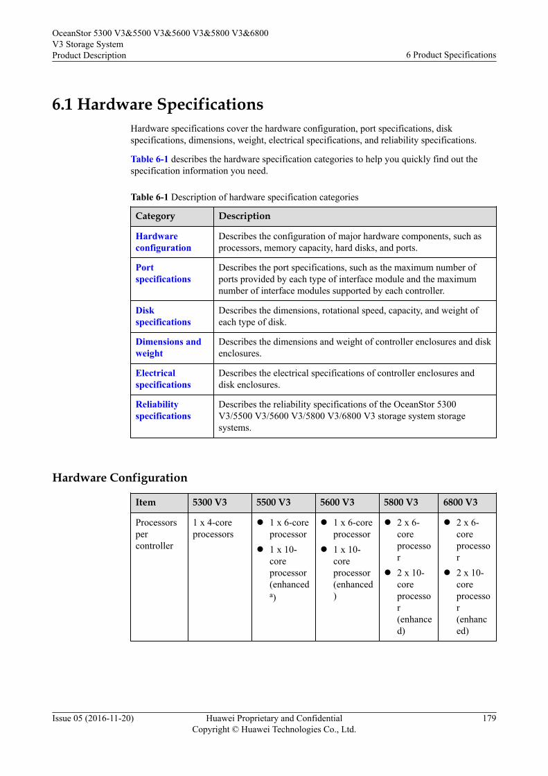
6.1 Hardware SpecificationsHardware specifications cover the hardware configuration, port specifications, diskspecifications, dimensions, weight, electrical specifications, and reliability specifications.
Table 6-1 describes the hardware specification categories to help you quickly find out thespecification information you need.
Table 6-1 Description of hardware specification categories
Category Description
Hardwareconfiguration
Describes the configuration of major hardware components, such asprocessors, memory capacity, hard disks, and ports.
Portspecifications
Describes the port specifications, such as the maximum number ofports provided by each type of interface module and the maximumnumber of interface modules supported by each controller.
Diskspecifications
Describes the dimensions, rotational speed, capacity, and weight ofeach type of disk.
Dimensions andweight
Describes the dimensions and weight of controller enclosures and diskenclosures.
Electricalspecifications
Describes the electrical specifications of controller enclosures anddisk enclosures.
Reliabilityspecifications
Describes the reliability specifications of the OceanStor 5300V3/5500 V3/5600 V3/5800 V3/6800 V3 storage system storagesystems.
Hardware Configuration
Item 5300 V3 5500 V3 5600 V3 5800 V3 6800 V3
Processorspercontroller
1 x 4-coreprocessors
l 1 x 6-coreprocessor
l 1 x 10-coreprocessor(enhanceda)
l 1 x 6-coreprocessor
l 1 x 10-coreprocessor(enhanced)
l 2 x 6-coreprocessor
l 2 x 10-coreprocessor(enhanced)
l 2 x 6-coreprocessor
l 2 x 10-coreprocessor(enhanced)
OceanStor 5300 V3&5500 V3&5600 V3&5800 V3&6800V3 Storage SystemProduct Description 6 Product Specifications
Issue 05 (2016-11-20) Huawei Proprietary and ConfidentialCopyright © Huawei Technologies Co., Ltd.
179
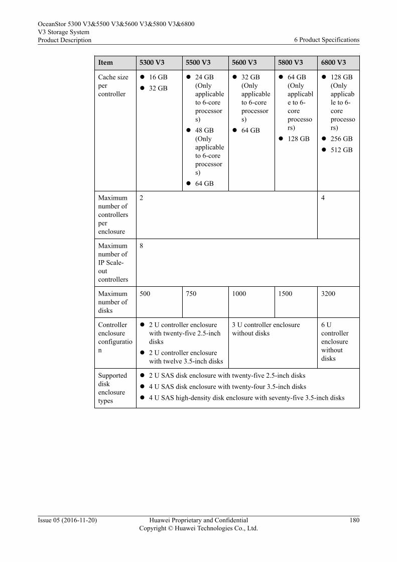
Item 5300 V3 5500 V3 5600 V3 5800 V3 6800 V3
Cache sizepercontroller
l 16 GBl 32 GB
l 24 GB(Onlyapplicableto 6-coreprocessors)
l 48 GB(Onlyapplicableto 6-coreprocessors)
l 64 GB
l 32 GB(Onlyapplicableto 6-coreprocessors)
l 64 GB
l 64 GB(Onlyapplicable to 6-coreprocessors)
l 128 GB
l 128 GB(Onlyapplicable to 6-coreprocessors)
l 256 GBl 512 GB
Maximumnumber ofcontrollersperenclosure
2 4
Maximumnumber ofIP Scale-outcontrollers
8
Maximumnumber ofdisks
500 750 1000 1500 3200
Controllerenclosureconfiguration
l 2 U controller enclosurewith twenty-five 2.5-inchdisks
l 2 U controller enclosurewith twelve 3.5-inch disks
3 U controller enclosurewithout disks
6 Ucontrollerenclosurewithoutdisks
Supporteddiskenclosuretypes
l 2 U SAS disk enclosure with twenty-five 2.5-inch disksl 4 U SAS disk enclosure with twenty-four 3.5-inch disksl 4 U SAS high-density disk enclosure with seventy-five 3.5-inch disks
OceanStor 5300 V3&5500 V3&5600 V3&5800 V3&6800V3 Storage SystemProduct Description 6 Product Specifications
Issue 05 (2016-11-20) Huawei Proprietary and ConfidentialCopyright © Huawei Technologies Co., Ltd.
180
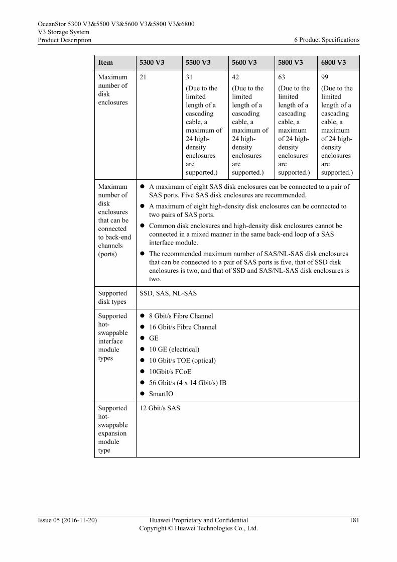
Item 5300 V3 5500 V3 5600 V3 5800 V3 6800 V3
Maximumnumber ofdiskenclosures
21 31(Due to thelimitedlength of acascadingcable, amaximum of24 high-densityenclosuresaresupported.)
42(Due to thelimitedlength of acascadingcable, amaximum of24 high-densityenclosuresaresupported.)
63(Due to thelimitedlength of acascadingcable, amaximumof 24 high-densityenclosuresaresupported.)
99(Due to thelimitedlength of acascadingcable, amaximumof 24 high-densityenclosuresaresupported.)
Maximumnumber ofdiskenclosuresthat can beconnectedto back-endchannels(ports)
l A maximum of eight SAS disk enclosures can be connected to a pair ofSAS ports. Five SAS disk enclosures are recommended.
l A maximum of eight high-density disk enclosures can be connected totwo pairs of SAS ports.
l Common disk enclosures and high-density disk enclosures cannot beconnected in a mixed manner in the same back-end loop of a SASinterface module.
l The recommended maximum number of SAS/NL-SAS disk enclosuresthat can be connected to a pair of SAS ports is five, that of SSD diskenclosures is two, and that of SSD and SAS/NL-SAS disk enclosures istwo.
Supporteddisk types
SSD, SAS, NL-SAS
Supportedhot-swappableinterfacemoduletypes
l 8 Gbit/s Fibre Channell 16 Gbit/s Fibre Channell GEl 10 GE (electrical)l 10 Gbit/s TOE (optical)l 10Gbit/s FCoEl 56 Gbit/s (4 x 14 Gbit/s) IBl SmartIO
Supportedhot-swappableexpansionmoduletype
12 Gbit/s SAS
OceanStor 5300 V3&5500 V3&5600 V3&5800 V3&6800V3 Storage SystemProduct Description 6 Product Specifications
Issue 05 (2016-11-20) Huawei Proprietary and ConfidentialCopyright © Huawei Technologies Co., Ltd.
181
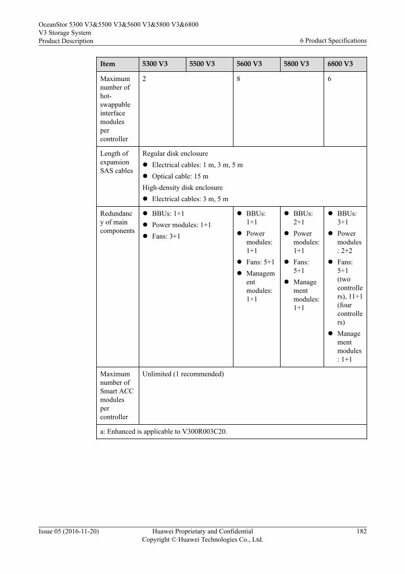
Item 5300 V3 5500 V3 5600 V3 5800 V3 6800 V3
Maximumnumber ofhot-swappableinterfacemodulespercontroller
2 8 6
Length ofexpansionSAS cables
Regular disk enclosurel Electrical cables: 1 m, 3 m, 5 ml Optical cable: 15 mHigh-density disk enclosurel Electrical cables: 3 m, 5 m
Redundancy of maincomponents
l BBUs: 1+1l Power modules: 1+1l Fans: 3+1
l BBUs:1+1
l Powermodules:1+1
l Fans: 5+1l Managem
entmodules:1+1
l BBUs:2+1
l Powermodules:1+1
l Fans:5+1
l Managementmodules:1+1
l BBUs:3+1
l Powermodules: 2+2
l Fans:5+1(twocontrollers), 11+1(fourcontrollers)
l Managementmodules: 1+1
Maximumnumber ofSmart ACCmodulespercontroller
Unlimited (1 recommended)
a: Enhanced is applicable to V300R003C20.
OceanStor 5300 V3&5500 V3&5600 V3&5800 V3&6800V3 Storage SystemProduct Description 6 Product Specifications
Issue 05 (2016-11-20) Huawei Proprietary and ConfidentialCopyright © Huawei Technologies Co., Ltd.
182
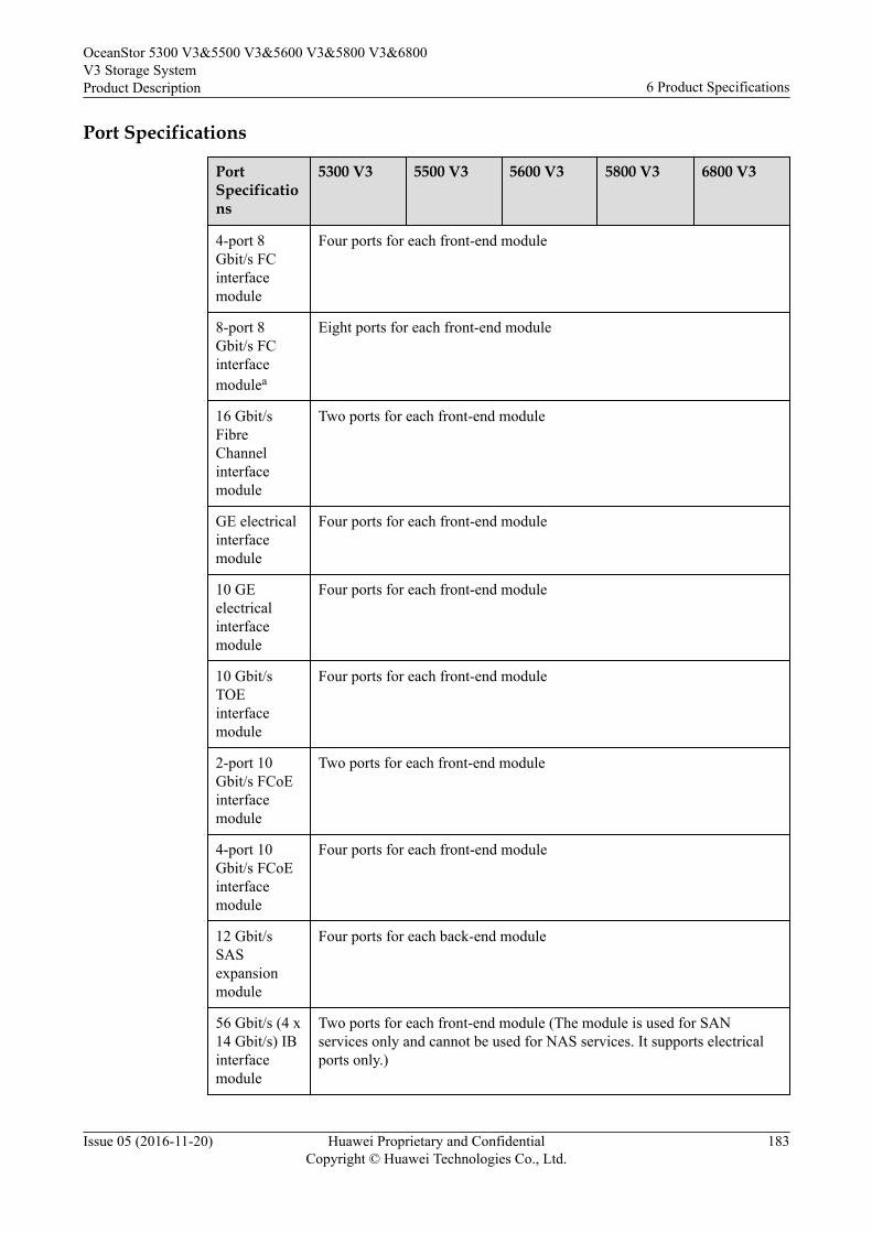
Port Specifications
PortSpecifications
5300 V3 5500 V3 5600 V3 5800 V3 6800 V3
4-port 8Gbit/s FCinterfacemodule
Four ports for each front-end module
8-port 8Gbit/s FCinterfacemodulea
Eight ports for each front-end module
16 Gbit/sFibreChannelinterfacemodule
Two ports for each front-end module
GE electricalinterfacemodule
Four ports for each front-end module
10 GEelectricalinterfacemodule
Four ports for each front-end module
10 Gbit/sTOEinterfacemodule
Four ports for each front-end module
2-port 10Gbit/s FCoEinterfacemodule
Two ports for each front-end module
4-port 10Gbit/s FCoEinterfacemodule
Four ports for each front-end module
12 Gbit/sSASexpansionmodule
Four ports for each back-end module
56 Gbit/s (4 x14 Gbit/s) IBinterfacemodule
Two ports for each front-end module (The module is used for SANservices only and cannot be used for NAS services. It supports electricalports only.)
OceanStor 5300 V3&5500 V3&5600 V3&5800 V3&6800V3 Storage SystemProduct Description 6 Product Specifications
Issue 05 (2016-11-20) Huawei Proprietary and ConfidentialCopyright © Huawei Technologies Co., Ltd.
183
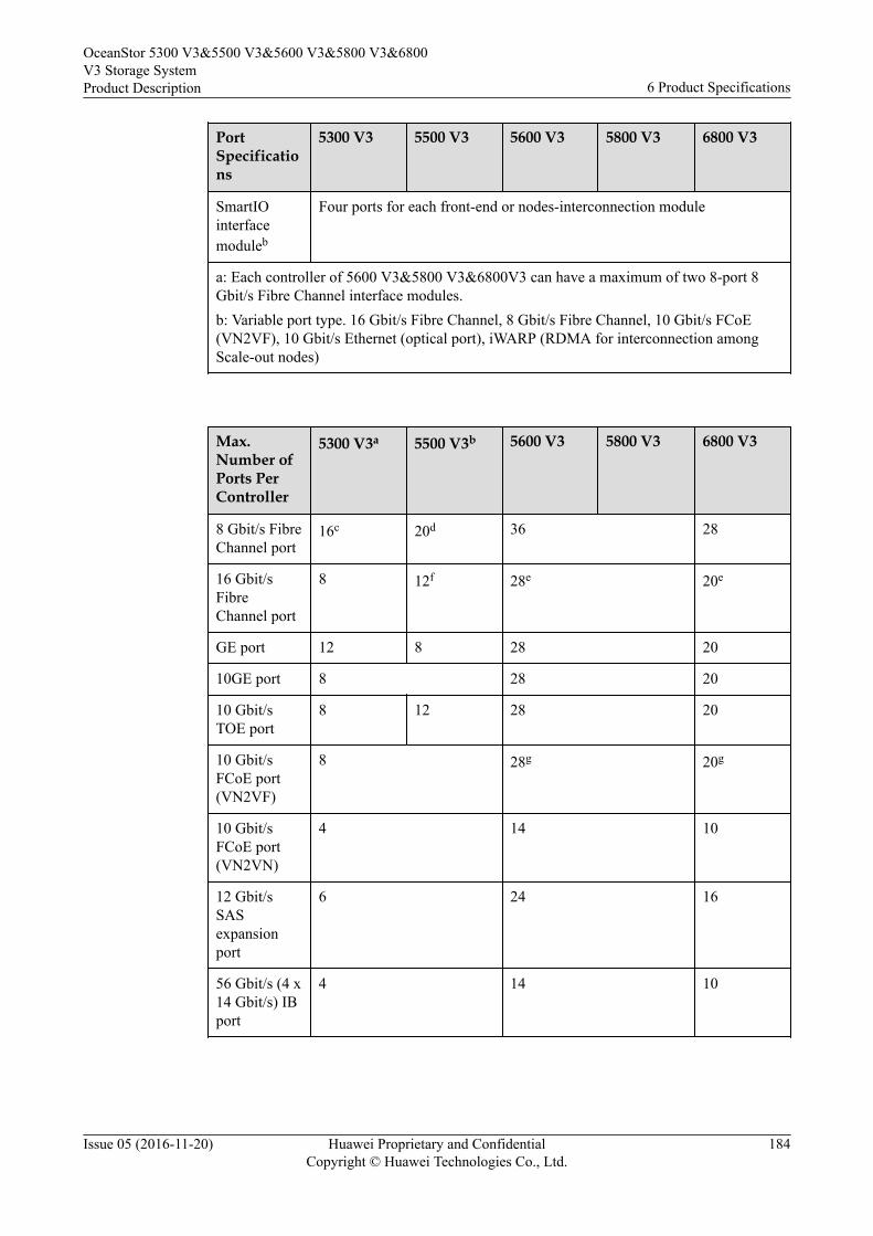
PortSpecifications
5300 V3 5500 V3 5600 V3 5800 V3 6800 V3
SmartIOinterfacemoduleb
Four ports for each front-end or nodes-interconnection module
a: Each controller of 5600 V3&5800 V3&6800V3 can have a maximum of two 8-port 8Gbit/s Fibre Channel interface modules.b: Variable port type. 16 Gbit/s Fibre Channel, 8 Gbit/s Fibre Channel, 10 Gbit/s FCoE(VN2VF), 10 Gbit/s Ethernet (optical port), iWARP (RDMA for interconnection amongScale-out nodes)
Max.Number ofPorts PerController
5300 V3a 5500 V3b 5600 V3 5800 V3 6800 V3
8 Gbit/s FibreChannel port
16c 20d 36 28
16 Gbit/sFibreChannel port
8 12f 28e 20e
GE port 12 8 28 20
10GE port 8 28 20
10 Gbit/sTOE port
8 12 28 20
10 Gbit/sFCoE port(VN2VF)
8 28g 20g
10 Gbit/sFCoE port(VN2VN)
4 14 10
12 Gbit/sSASexpansionport
6 24 16
56 Gbit/s (4 x14 Gbit/s) IBport
4 14 10
OceanStor 5300 V3&5500 V3&5600 V3&5800 V3&6800V3 Storage SystemProduct Description 6 Product Specifications
Issue 05 (2016-11-20) Huawei Proprietary and ConfidentialCopyright © Huawei Technologies Co., Ltd.
184
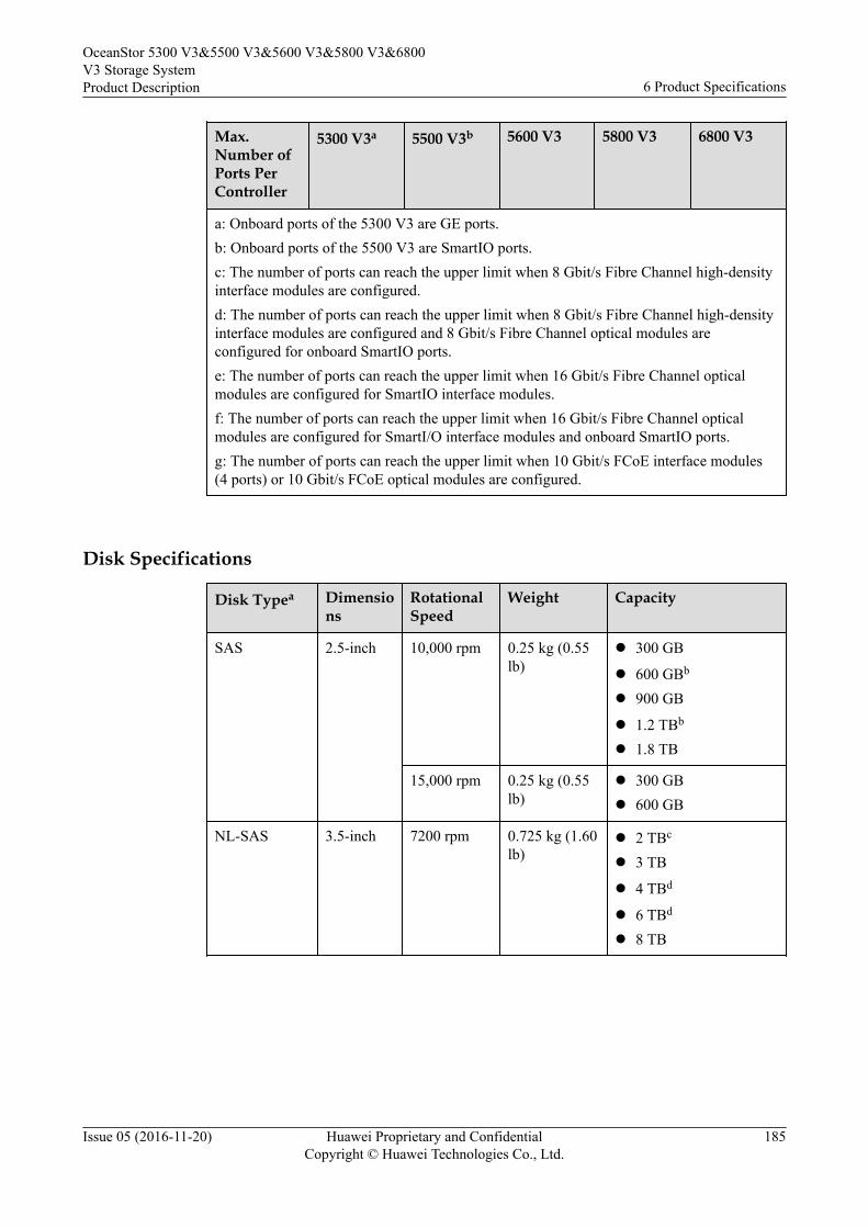
Max.Number ofPorts PerController
5300 V3a 5500 V3b 5600 V3 5800 V3 6800 V3
a: Onboard ports of the 5300 V3 are GE ports.b: Onboard ports of the 5500 V3 are SmartIO ports.c: The number of ports can reach the upper limit when 8 Gbit/s Fibre Channel high-densityinterface modules are configured.d: The number of ports can reach the upper limit when 8 Gbit/s Fibre Channel high-densityinterface modules are configured and 8 Gbit/s Fibre Channel optical modules areconfigured for onboard SmartIO ports.e: The number of ports can reach the upper limit when 16 Gbit/s Fibre Channel opticalmodules are configured for SmartIO interface modules.f: The number of ports can reach the upper limit when 16 Gbit/s Fibre Channel opticalmodules are configured for SmartI/O interface modules and onboard SmartIO ports.g: The number of ports can reach the upper limit when 10 Gbit/s FCoE interface modules(4 ports) or 10 Gbit/s FCoE optical modules are configured.
Disk Specifications
Disk Typea Dimensions
RotationalSpeed
Weight Capacity
SAS 2.5-inch 10,000 rpm 0.25 kg (0.55lb)
l 300 GB
l 600 GBb
l 900 GB
l 1.2 TBb
l 1.8 TB
15,000 rpm 0.25 kg (0.55lb)
l 300 GBl 600 GB
NL-SAS 3.5-inch 7200 rpm 0.725 kg (1.60lb)
l 2 TBc
l 3 TB
l 4 TBd
l 6 TBd
l 8 TB
OceanStor 5300 V3&5500 V3&5600 V3&5800 V3&6800V3 Storage SystemProduct Description 6 Product Specifications
Issue 05 (2016-11-20) Huawei Proprietary and ConfidentialCopyright © Huawei Technologies Co., Ltd.
185
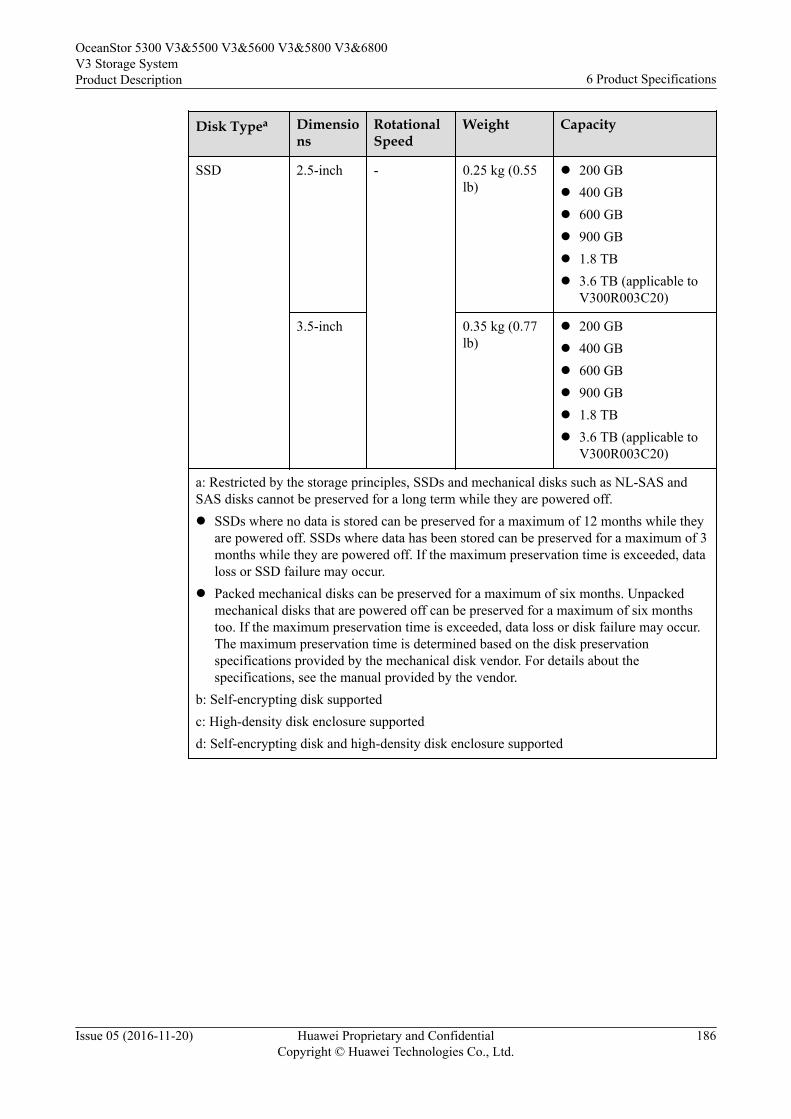
Disk Typea Dimensions
RotationalSpeed
Weight Capacity
SSD 2.5-inch - 0.25 kg (0.55lb)
l 200 GBl 400 GBl 600 GBl 900 GBl 1.8 TBl 3.6 TB (applicable to
V300R003C20)
3.5-inch 0.35 kg (0.77lb)
l 200 GBl 400 GBl 600 GBl 900 GBl 1.8 TBl 3.6 TB (applicable to
V300R003C20)
a: Restricted by the storage principles, SSDs and mechanical disks such as NL-SAS andSAS disks cannot be preserved for a long term while they are powered off.l SSDs where no data is stored can be preserved for a maximum of 12 months while they
are powered off. SSDs where data has been stored can be preserved for a maximum of 3months while they are powered off. If the maximum preservation time is exceeded, dataloss or SSD failure may occur.
l Packed mechanical disks can be preserved for a maximum of six months. Unpackedmechanical disks that are powered off can be preserved for a maximum of six monthstoo. If the maximum preservation time is exceeded, data loss or disk failure may occur.The maximum preservation time is determined based on the disk preservationspecifications provided by the mechanical disk vendor. For details about thespecifications, see the manual provided by the vendor.
b: Self-encrypting disk supportedc: High-density disk enclosure supportedd: Self-encrypting disk and high-density disk enclosure supported
OceanStor 5300 V3&5500 V3&5600 V3&5800 V3&6800V3 Storage SystemProduct Description 6 Product Specifications
Issue 05 (2016-11-20) Huawei Proprietary and ConfidentialCopyright © Huawei Technologies Co., Ltd.
186
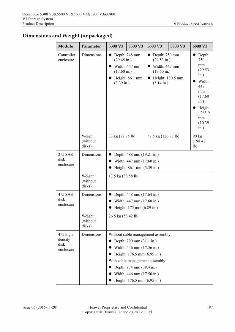
Dimensions and Weight (unpackaged)
Module Parameter 5300 V3 5500 V3 5600 V3 5800 V3 6800 V3
Controllerenclosure
Dimensions l Depth: 748 mm(29.45 in.)
l Width: 447 mm(17.60 in.)
l Height: 86.1 mm(3.39 in.)
l Depth: 750 mm(29.53 in.)
l Width: 447 mm(17.60 in.)
l Height: 130.5 mm(5.14 in.)
l Depth:750mm(29.53in.)
l Width:447mm(17.60in.)
l Height: 263.9mm(10.39in.)
Weight(withoutdisks)
33 kg (72.75 lb) 57.5 kg (126.77 lb) 90 kg(198.42lb)
2 U SASdiskenclosure
Dimensions l Depth: 488 mm (19.21 in.)l Width: 447 mm (17.60 in.)l Height: 86.1 mm (3.39 in.)
Weight(withoutdisks)
17.5 kg (38.58 lb)
4 U SASdiskenclosure
Dimensions l Depth: 448 mm (17.64 in.)l Width: 447 mm (17.60 in.)l Height: 175 mm (6.89 in.)
Weight(withoutdisks)
26.5 kg (58.42 lb)
4 U high-densitydiskenclosure
Dimensions Without cable management assembly:l Depth: 790 mm (31.1 in.)l Width: 446 mm (17.56 in.)l Height: 176.5 mm (6.95 in.)With cable management assembly:l Depth: 974 mm (38.4 in.)l Width: 446 mm (17.56 in.)l Height: 176.5 mm (6.95 in.)
OceanStor 5300 V3&5500 V3&5600 V3&5800 V3&6800V3 Storage SystemProduct Description 6 Product Specifications
Issue 05 (2016-11-20) Huawei Proprietary and ConfidentialCopyright © Huawei Technologies Co., Ltd.
187
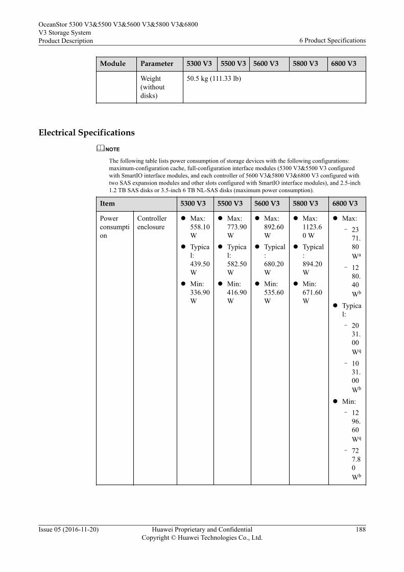
Module Parameter 5300 V3 5500 V3 5600 V3 5800 V3 6800 V3
Weight(withoutdisks)
50.5 kg (111.33 lb)
Electrical Specifications
NOTE
The following table lists power consumption of storage devices with the following configurations:maximum-configuration cache, full-configuration interface modules (5300 V3&5500 V3 configuredwith SmartIO interface modules, and each controller of 5600 V3&5800 V3&6800 V3 configured withtwo SAS expansion modules and other slots configured with SmartIO interface modules), and 2.5-inch1.2 TB SAS disks or 3.5-inch 6 TB NL-SAS disks (maximum power consumption).
Item 5300 V3 5500 V3 5600 V3 5800 V3 6800 V3
Powerconsumption
Controllerenclosure
l Max:558.10W
l Typical:439.50W
l Min:336.90W
l Max:773.90W
l Typical:582.50W
l Min:416.90W
l Max:892.60W
l Typical:680.20W
l Min:535.60W
l Max:1123.60 W
l Typical:894.20W
l Min:671.60W
l Max:– 23
71.80Wa
– 1280.40Wb
l Typical:– 20
31.00Wq
– 1031.00Wb
l Min:– 12
96.60Wq
– 727.80Wb
OceanStor 5300 V3&5500 V3&5600 V3&5800 V3&6800V3 Storage SystemProduct Description 6 Product Specifications
Issue 05 (2016-11-20) Huawei Proprietary and ConfidentialCopyright © Huawei Technologies Co., Ltd.
188
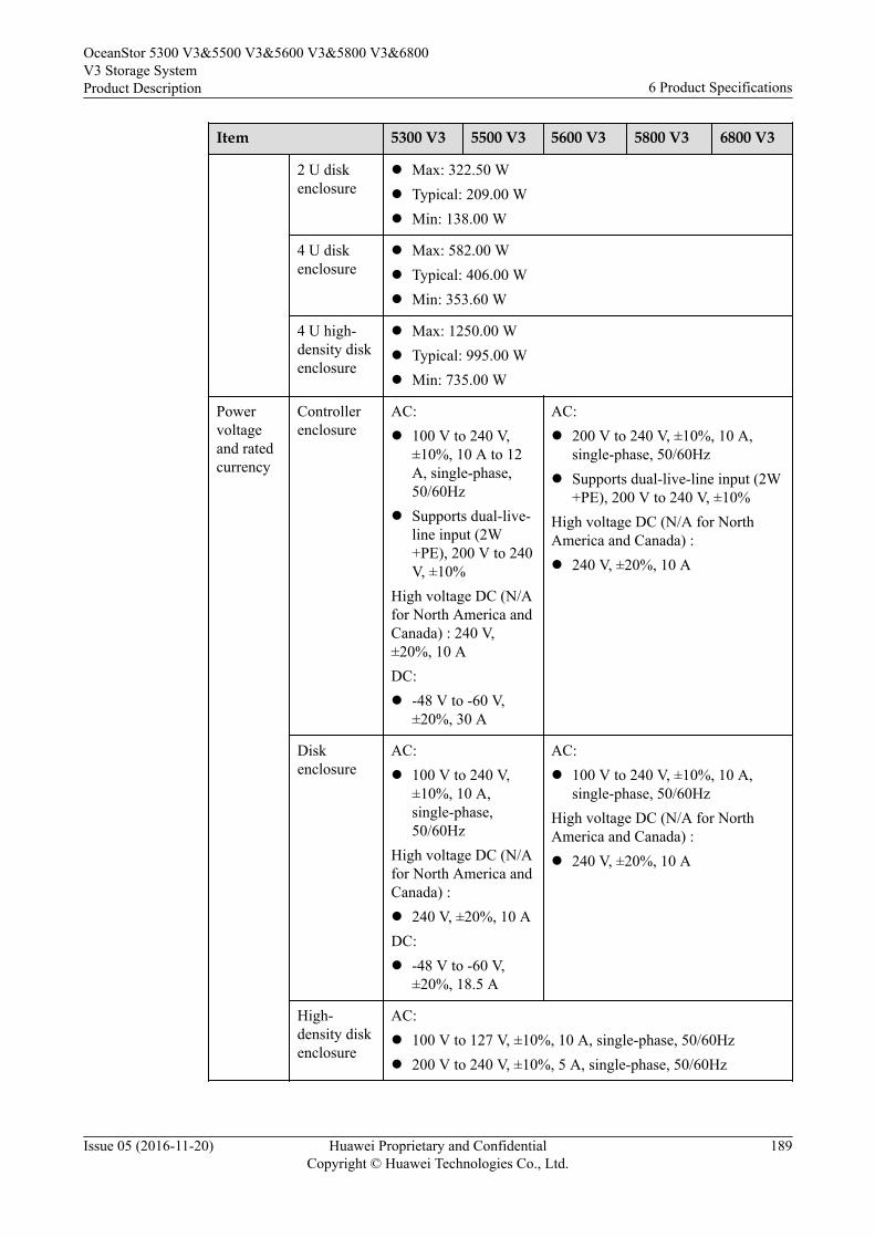
Item 5300 V3 5500 V3 5600 V3 5800 V3 6800 V3
2 U diskenclosure
l Max: 322.50 Wl Typical: 209.00 Wl Min: 138.00 W
4 U diskenclosure
l Max: 582.00 Wl Typical: 406.00 Wl Min: 353.60 W
4 U high-density diskenclosure
l Max: 1250.00 Wl Typical: 995.00 Wl Min: 735.00 W
Powervoltageand ratedcurrency
Controllerenclosure
AC:l 100 V to 240 V,
±10%, 10 A to 12A, single-phase,50/60Hz
l Supports dual-live-line input (2W+PE), 200 V to 240V, ±10%
High voltage DC (N/Afor North America andCanada) : 240 V,±20%, 10 ADC:l -48 V to -60 V,
±20%, 30 A
AC:l 200 V to 240 V, ±10%, 10 A,
single-phase, 50/60Hzl Supports dual-live-line input (2W
+PE), 200 V to 240 V, ±10%High voltage DC (N/A for NorthAmerica and Canada) :l 240 V, ±20%, 10 A
Diskenclosure
AC:l 100 V to 240 V,
±10%, 10 A,single-phase,50/60Hz
High voltage DC (N/Afor North America andCanada) :l 240 V, ±20%, 10 ADC:l -48 V to -60 V,
±20%, 18.5 A
AC:l 100 V to 240 V, ±10%, 10 A,
single-phase, 50/60HzHigh voltage DC (N/A for NorthAmerica and Canada) :l 240 V, ±20%, 10 A
High-density diskenclosure
AC:l 100 V to 127 V, ±10%, 10 A, single-phase, 50/60Hzl 200 V to 240 V, ±10%, 5 A, single-phase, 50/60Hz
OceanStor 5300 V3&5500 V3&5600 V3&5800 V3&6800V3 Storage SystemProduct Description 6 Product Specifications
Issue 05 (2016-11-20) Huawei Proprietary and ConfidentialCopyright © Huawei Technologies Co., Ltd.
189
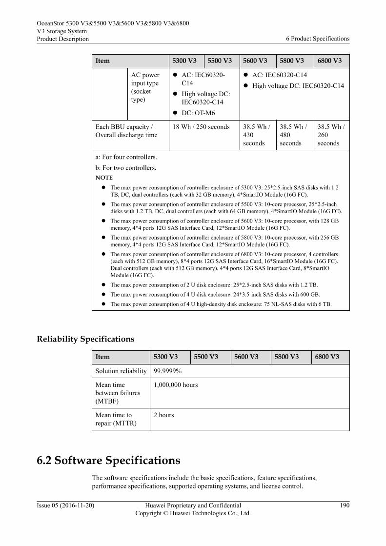
Item 5300 V3 5500 V3 5600 V3 5800 V3 6800 V3
AC powerinput type(sockettype)
l AC: IEC60320-C14
l High voltage DC:IEC60320-C14
l DC: OT-M6
l AC: IEC60320-C14l High voltage DC: IEC60320-C14
Each BBU capacity /Overall discharge time
18 Wh / 250 seconds 38.5 Wh /430seconds
38.5 Wh /480seconds
38.5 Wh /260seconds
a: For four controllers.b: For two controllers.NOTE
l The max power consumption of controller enclosure of 5300 V3: 25*2.5-inch SAS disks with 1.2TB, DC, dual controllers (each with 32 GB memory), 4*SmartIO Module (16G FC).
l The max power consumption of controller enclosure of 5500 V3: 10-core processor, 25*2.5-inchdisks with 1.2 TB, DC, dual controllers (each with 64 GB memory), 4*SmartIO Module (16G FC).
l The max power consumption of controller enclosure of 5600 V3: 10-core processor, with 128 GBmemory, 4*4 ports 12G SAS Interface Card, 12*SmartIO Module (16G FC).
l The max power consumption of controller enclosure of 5800 V3: 10-core processor, with 256 GBmemory, 4*4 ports 12G SAS Interface Card, 12*SmartIO Module (16G FC).
l The max power consumption of controller enclosure of 6800 V3: 10-core processor, 4 controllers(each with 512 GB memory), 8*4 ports 12G SAS Interface Card, 16*SmartIO Module (16G FC).Dual controllers (each with 512 GB memory), 4*4 ports 12G SAS Interface Card, 8*SmartIOModule (16G FC).
l The max power consumption of 2 U disk enclosure: 25*2.5-inch SAS disks with 1.2 TB.
l The max power consumption of 4 U disk enclosure: 24*3.5-inch SAS disks with 600 GB.
l The max power consumption of 4 U high-density disk enclosure: 75 NL-SAS disks with 6 TB.
Reliability Specifications
Item 5300 V3 5500 V3 5600 V3 5800 V3 6800 V3
Solution reliability 99.9999%
Mean timebetween failures(MTBF)
1,000,000 hours
Mean time torepair (MTTR)
2 hours
6.2 Software SpecificationsThe software specifications include the basic specifications, feature specifications,performance specifications, supported operating systems, and license control.
OceanStor 5300 V3&5500 V3&5600 V3&5800 V3&6800V3 Storage SystemProduct Description 6 Product Specifications
Issue 05 (2016-11-20) Huawei Proprietary and ConfidentialCopyright © Huawei Technologies Co., Ltd.
190
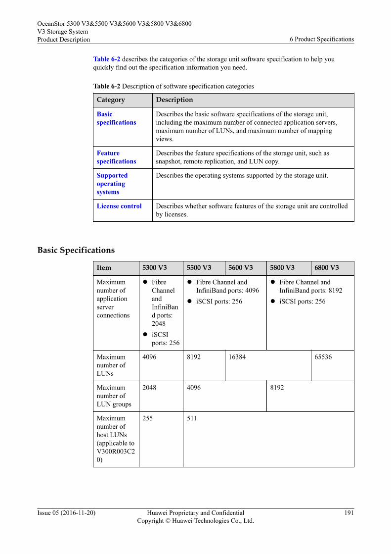
Table 6-2 describes the categories of the storage unit software specification to help youquickly find out the specification information you need.
Table 6-2 Description of software specification categories
Category Description
Basicspecifications
Describes the basic software specifications of the storage unit,including the maximum number of connected application servers,maximum number of LUNs, and maximum number of mappingviews.
Featurespecifications
Describes the feature specifications of the storage unit, such assnapshot, remote replication, and LUN copy.
Supportedoperatingsystems
Describes the operating systems supported by the storage unit.
License control Describes whether software features of the storage unit are controlledby licenses.
Basic Specifications
Item 5300 V3 5500 V3 5600 V3 5800 V3 6800 V3
Maximumnumber ofapplicationserverconnections
l FibreChannelandInfiniBand ports:2048
l iSCSIports: 256
l Fibre Channel andInfiniBand ports: 4096
l iSCSI ports: 256
l Fibre Channel andInfiniBand ports: 8192
l iSCSI ports: 256
Maximumnumber ofLUNs
4096 8192 16384 65536
Maximumnumber ofLUN groups
2048 4096 8192
Maximumnumber ofhost LUNs(applicable toV300R003C20)
255 511
OceanStor 5300 V3&5500 V3&5600 V3&5800 V3&6800V3 Storage SystemProduct Description 6 Product Specifications
Issue 05 (2016-11-20) Huawei Proprietary and ConfidentialCopyright © Huawei Technologies Co., Ltd.
191
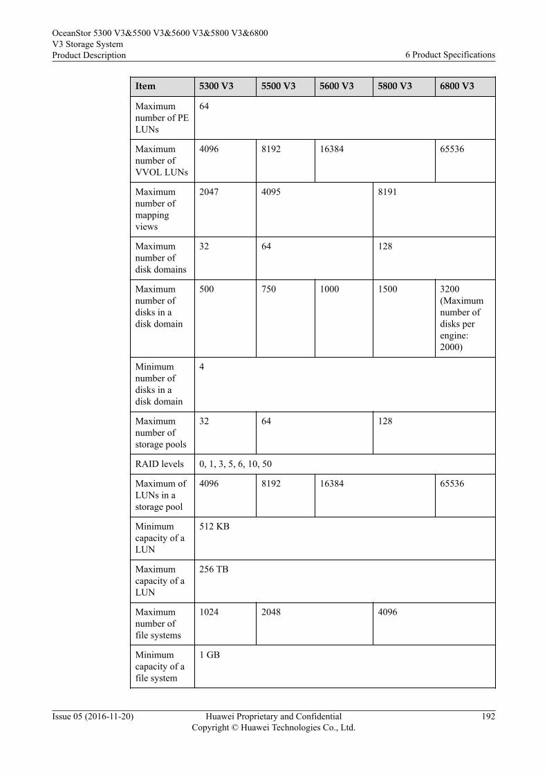
Item 5300 V3 5500 V3 5600 V3 5800 V3 6800 V3
Maximumnumber of PELUNs
64
Maximumnumber ofVVOL LUNs
4096 8192 16384 65536
Maximumnumber ofmappingviews
2047 4095 8191
Maximumnumber ofdisk domains
32 64 128
Maximumnumber ofdisks in adisk domain
500 750 1000 1500 3200(Maximumnumber ofdisks perengine:2000)
Minimumnumber ofdisks in adisk domain
4
Maximumnumber ofstorage pools
32 64 128
RAID levels 0, 1, 3, 5, 6, 10, 50
Maximum ofLUNs in astorage pool
4096 8192 16384 65536
Minimumcapacity of aLUN
512 KB
Maximumcapacity of aLUN
256 TB
Maximumnumber offile systems
1024 2048 4096
Minimumcapacity of afile system
1 GB
OceanStor 5300 V3&5500 V3&5600 V3&5800 V3&6800V3 Storage SystemProduct Description 6 Product Specifications
Issue 05 (2016-11-20) Huawei Proprietary and ConfidentialCopyright © Huawei Technologies Co., Ltd.
192
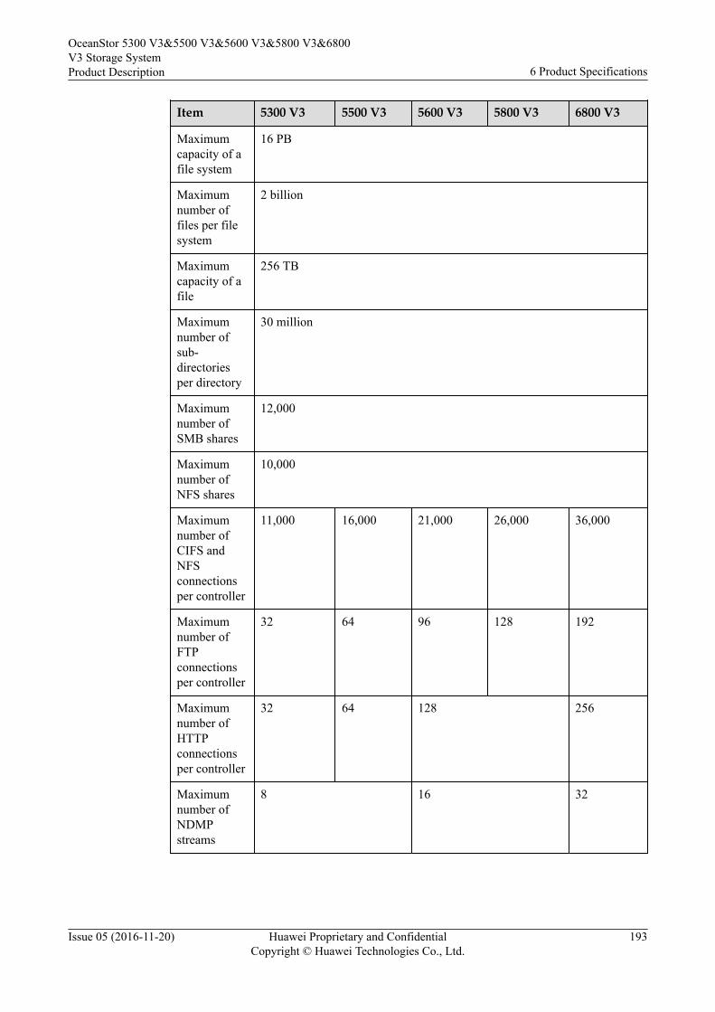
Item 5300 V3 5500 V3 5600 V3 5800 V3 6800 V3
Maximumcapacity of afile system
16 PB
Maximumnumber offiles per filesystem
2 billion
Maximumcapacity of afile
256 TB
Maximumnumber ofsub-directoriesper directory
30 million
Maximumnumber ofSMB shares
12,000
Maximumnumber ofNFS shares
10,000
Maximumnumber ofCIFS andNFSconnectionsper controller
11,000 16,000 21,000 26,000 36,000
Maximumnumber ofFTPconnectionsper controller
32 64 96 128 192
Maximumnumber ofHTTPconnectionsper controller
32 64 128 256
Maximumnumber ofNDMPstreams
8 16 32
OceanStor 5300 V3&5500 V3&5600 V3&5800 V3&6800V3 Storage SystemProduct Description 6 Product Specifications
Issue 05 (2016-11-20) Huawei Proprietary and ConfidentialCopyright © Huawei Technologies Co., Ltd.
193
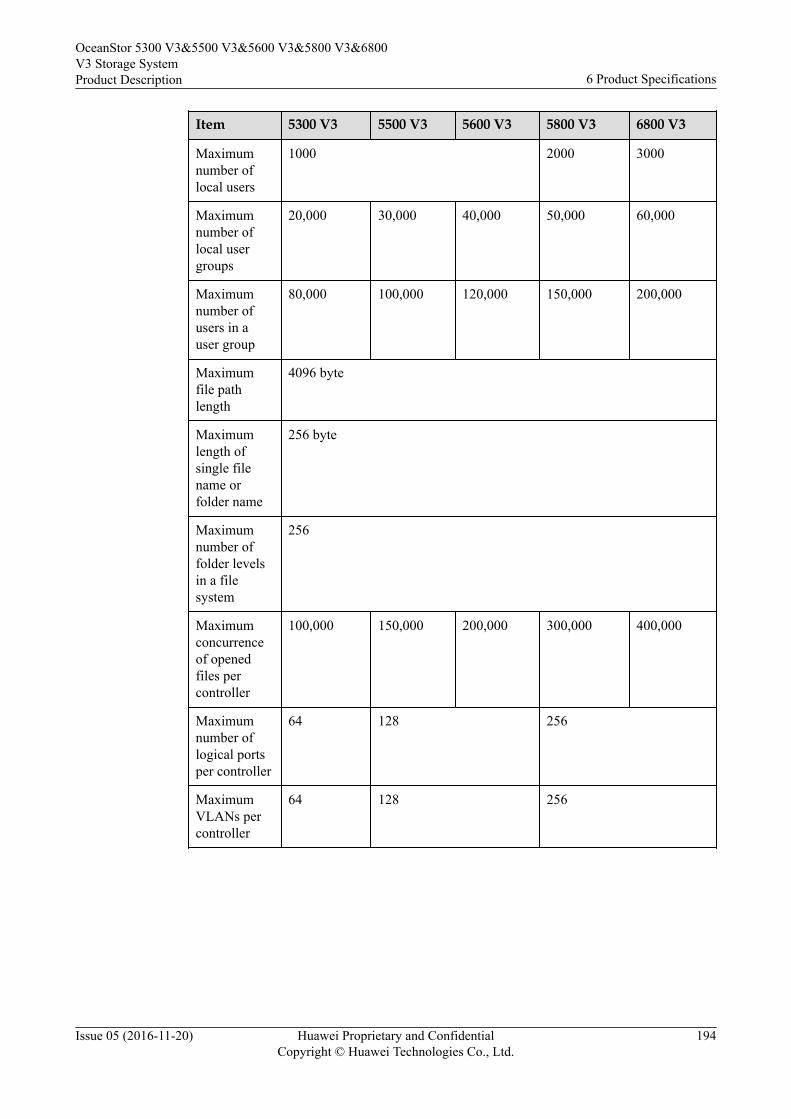
Item 5300 V3 5500 V3 5600 V3 5800 V3 6800 V3
Maximumnumber oflocal users
1000 2000 3000
Maximumnumber oflocal usergroups
20,000 30,000 40,000 50,000 60,000
Maximumnumber ofusers in auser group
80,000 100,000 120,000 150,000 200,000
Maximumfile pathlength
4096 byte
Maximumlength ofsingle filename orfolder name
256 byte
Maximumnumber offolder levelsin a filesystem
256
Maximumconcurrenceof openedfiles percontroller
100,000 150,000 200,000 300,000 400,000
Maximumnumber oflogical portsper controller
64 128 256
MaximumVLANs percontroller
64 128 256
OceanStor 5300 V3&5500 V3&5600 V3&5800 V3&6800V3 Storage SystemProduct Description 6 Product Specifications
Issue 05 (2016-11-20) Huawei Proprietary and ConfidentialCopyright © Huawei Technologies Co., Ltd.
194
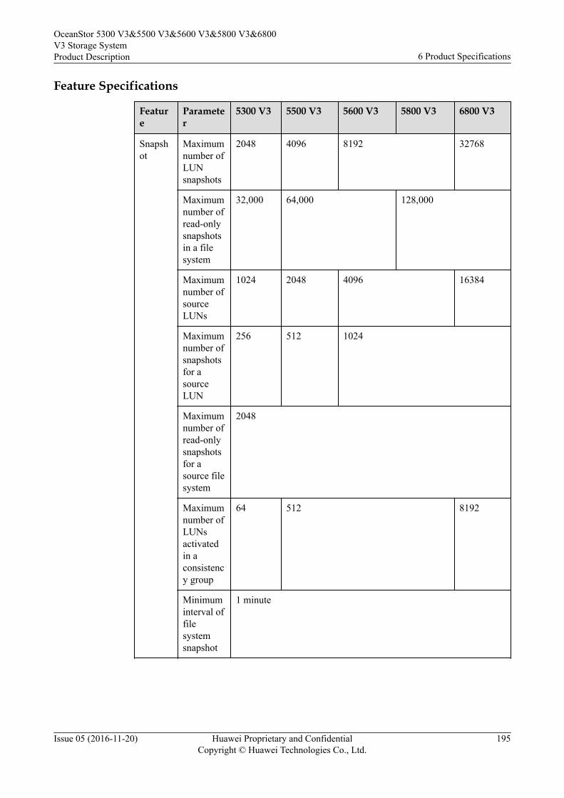
Feature Specifications
Feature
Parameter
5300 V3 5500 V3 5600 V3 5800 V3 6800 V3
Snapshot
Maximumnumber ofLUNsnapshots
2048 4096 8192 32768
Maximumnumber ofread-onlysnapshotsin a filesystem
32,000 64,000 128,000
Maximumnumber ofsourceLUNs
1024 2048 4096 16384
Maximumnumber ofsnapshotsfor asourceLUN
256 512 1024
Maximumnumber ofread-onlysnapshotsfor asource filesystem
2048
Maximumnumber ofLUNsactivatedin aconsistency group
64 512 8192
Minimuminterval offilesystemsnapshot
1 minute
OceanStor 5300 V3&5500 V3&5600 V3&5800 V3&6800V3 Storage SystemProduct Description 6 Product Specifications
Issue 05 (2016-11-20) Huawei Proprietary and ConfidentialCopyright © Huawei Technologies Co., Ltd.
195
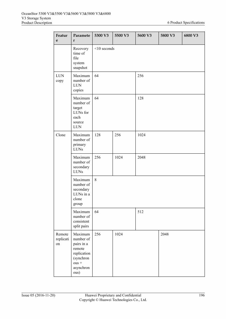
Feature
Parameter
5300 V3 5500 V3 5600 V3 5800 V3 6800 V3
Recoverytime offilesystemsnapshot
<10 seconds
LUNcopy
Maximumnumber ofLUNcopies
64 256
Maximumnumber oftargetLUNs foreachsourceLUN
64 128
Clone Maximumnumber ofprimaryLUNs
128 256 1024
Maximumnumber ofsecondaryLUNs
256 1024 2048
Maximumnumber ofsecondaryLUNs in aclonegroup
8
Maximumnumber ofconsistentsplit pairs
64 512
Remotereplication
Maximumnumber ofpairs in aremotereplication(synchronous +asynchronous)
256 1024 2048
OceanStor 5300 V3&5500 V3&5600 V3&5800 V3&6800V3 Storage SystemProduct Description 6 Product Specifications
Issue 05 (2016-11-20) Huawei Proprietary and ConfidentialCopyright © Huawei Technologies Co., Ltd.
196
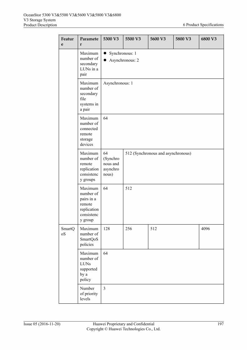
Feature
Parameter
5300 V3 5500 V3 5600 V3 5800 V3 6800 V3
Maximumnumber ofsecondaryLUNs in apair
l Synchronous: 1l Asynchronous: 2
Maximumnumber ofsecondaryfilesystems ina pair
Asynchronous: 1
Maximumnumber ofconnectedremotestoragedevices
64
Maximumnumber ofremotereplicationconsistency groups
64(Synchronous andasynchronous)
512 (Synchronous and asynchronous)
Maximumnumber ofpairs in aremotereplicationconsistency group
64 512
SmartQoS
Maximumnumber ofSmartQoSpolicies
128 256 512 4096
Maximumnumber ofLUNssupportedby apolicy
64
Numberof prioritylevels
3
OceanStor 5300 V3&5500 V3&5600 V3&5800 V3&6800V3 Storage SystemProduct Description 6 Product Specifications
Issue 05 (2016-11-20) Huawei Proprietary and ConfidentialCopyright © Huawei Technologies Co., Ltd.
197
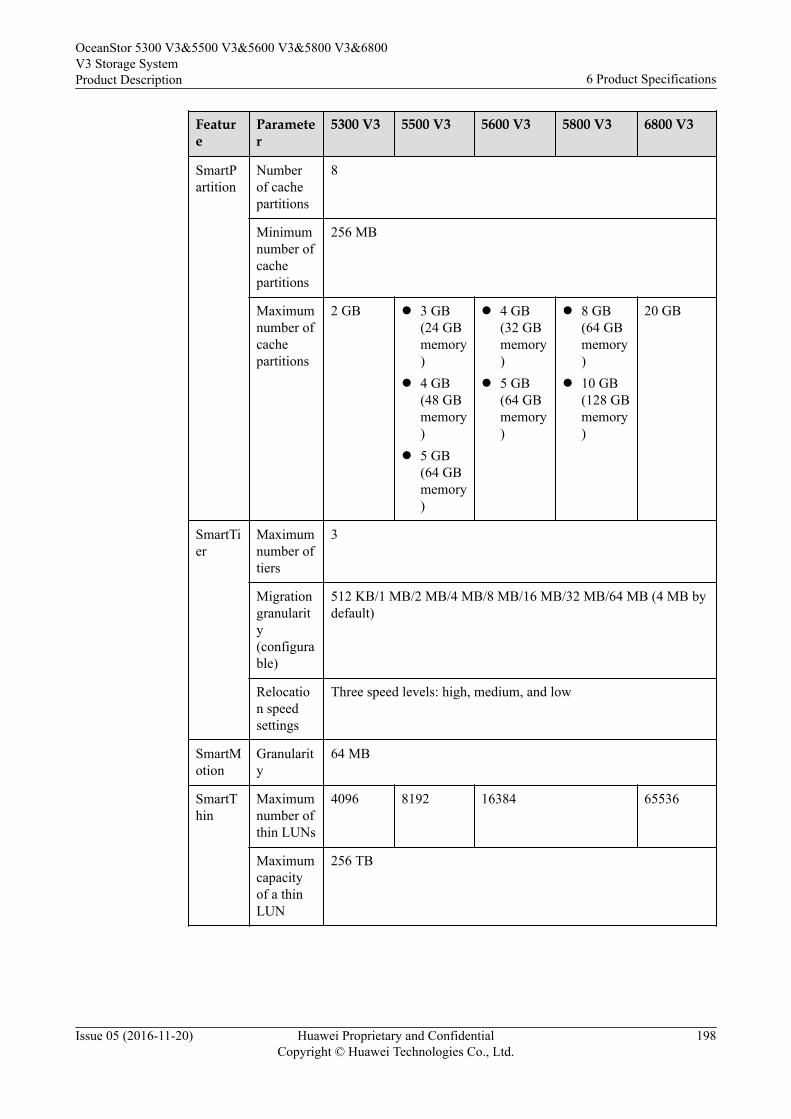
Feature
Parameter
5300 V3 5500 V3 5600 V3 5800 V3 6800 V3
SmartPartition
Numberof cachepartitions
8
Minimumnumber ofcachepartitions
256 MB
Maximumnumber ofcachepartitions
2 GB l 3 GB(24 GBmemory)
l 4 GB(48 GBmemory)
l 5 GB(64 GBmemory)
l 4 GB(32 GBmemory)
l 5 GB(64 GBmemory)
l 8 GB(64 GBmemory)
l 10 GB(128 GBmemory)
20 GB
SmartTier
Maximumnumber oftiers
3
Migrationgranularity(configurable)
512 KB/1 MB/2 MB/4 MB/8 MB/16 MB/32 MB/64 MB (4 MB bydefault)
Relocation speedsettings
Three speed levels: high, medium, and low
SmartMotion
Granularity
64 MB
SmartThin
Maximumnumber ofthin LUNs
4096 8192 16384 65536
Maximumcapacityof a thinLUN
256 TB
OceanStor 5300 V3&5500 V3&5600 V3&5800 V3&6800V3 Storage SystemProduct Description 6 Product Specifications
Issue 05 (2016-11-20) Huawei Proprietary and ConfidentialCopyright © Huawei Technologies Co., Ltd.
198
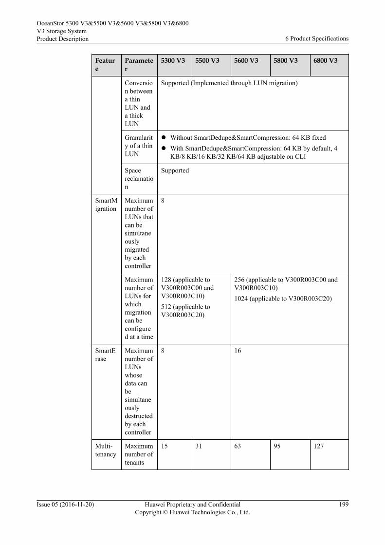
Feature
Parameter
5300 V3 5500 V3 5600 V3 5800 V3 6800 V3
Conversion betweena thinLUN anda thickLUN
Supported (Implemented through LUN migration)
Granularity of a thinLUN
l Without SmartDedupe&SmartCompression: 64 KB fixedl With SmartDedupe&SmartCompression: 64 KB by default, 4
KB/8 KB/16 KB/32 KB/64 KB adjustable on CLI
Spacereclamation
Supported
SmartMigration
Maximumnumber ofLUNs thatcan besimultaneouslymigratedby eachcontroller
8
Maximumnumber ofLUNs forwhichmigrationcan beconfigured at a time
128 (applicable toV300R003C00 andV300R003C10)512 (applicable toV300R003C20)
256 (applicable to V300R003C00 andV300R003C10)1024 (applicable to V300R003C20)
SmartErase
Maximumnumber ofLUNswhosedata canbesimultaneouslydestructedby eachcontroller
8 16
Multi-tenancy
Maximumnumber oftenants
15 31 63 95 127
OceanStor 5300 V3&5500 V3&5600 V3&5800 V3&6800V3 Storage SystemProduct Description 6 Product Specifications
Issue 05 (2016-11-20) Huawei Proprietary and ConfidentialCopyright © Huawei Technologies Co., Ltd.
199
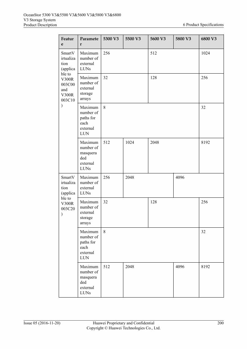
Feature
Parameter
5300 V3 5500 V3 5600 V3 5800 V3 6800 V3
SmartVirtualization(applicable toV300R003C00andV300R003C10)
Maximumnumber ofexternalLUNs
256 512 1024
Maximumnumber ofexternalstoragearrays
32 128 256
Maximumnumber ofpaths foreachexternalLUN
8 32
Maximumnumber ofmasqueradedexternalLUNs
512 1024 2048 8192
SmartVirtualization(applicable toV300R003C20)
Maximumnumber ofexternalLUNs
256 2048 4096
Maximumnumber ofexternalstoragearrays
32 128 256
Maximumnumber ofpaths foreachexternalLUN
8 32
Maximumnumber ofmasqueradedexternalLUNs
512 2048 4096 8192
OceanStor 5300 V3&5500 V3&5600 V3&5800 V3&6800V3 Storage SystemProduct Description 6 Product Specifications
Issue 05 (2016-11-20) Huawei Proprietary and ConfidentialCopyright © Huawei Technologies Co., Ltd.
200
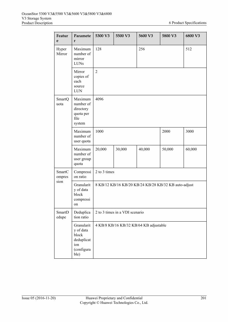
Feature
Parameter
5300 V3 5500 V3 5600 V3 5800 V3 6800 V3
HyperMirror
Maximumnumber ofmirrorLUNs
128 256 512
Mirrorcopies ofeachsourceLUN
2
SmartQuota
Maximumnumber ofdirectoryquota perfilesystem
4096
Maximumnumber ofuser quota
1000 2000 3000
Maximumnumber ofuser groupquota
20,000 30,000 40,000 50,000 60,000
SmartCompression
Compression ratio
2 to 3 times
Granularity of datablockcompression
8 KB/12 KB/16 KB/20 KB/24 KB/28 KB/32 KB auto-adjust
SmartDedupe
Deduplication ratio
2 to 3 times in a VDI scenario
Granularity of datablockdeduplication(configurable)
4 KB/8 KB/16 KB/32 KB/64 KB adjustable
OceanStor 5300 V3&5500 V3&5600 V3&5800 V3&6800V3 Storage SystemProduct Description 6 Product Specifications
Issue 05 (2016-11-20) Huawei Proprietary and ConfidentialCopyright © Huawei Technologies Co., Ltd.
201
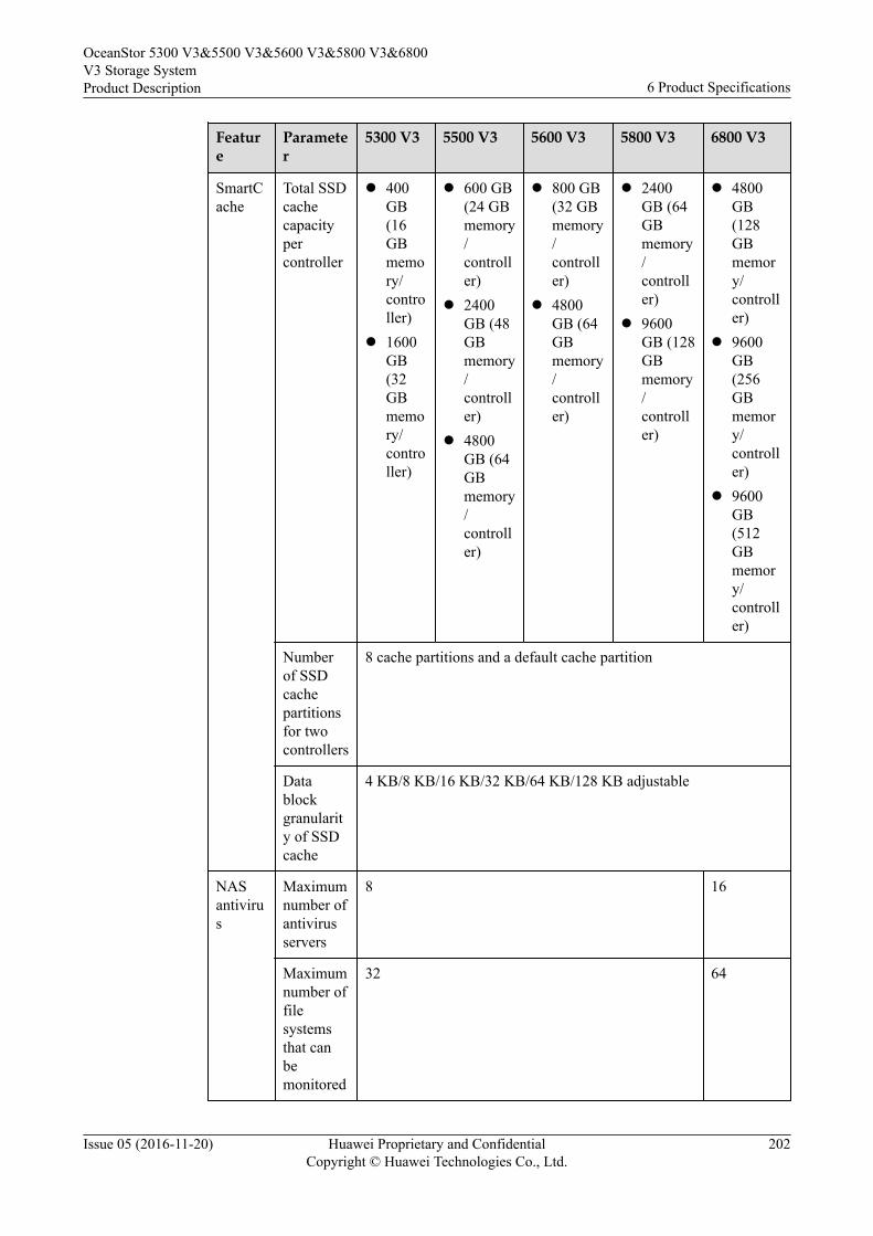
Feature
Parameter
5300 V3 5500 V3 5600 V3 5800 V3 6800 V3
SmartCache
Total SSDcachecapacitypercontroller
l 400GB(16GBmemory/controller)
l 1600GB(32GBmemory/controller)
l 600 GB(24 GBmemory/controller)
l 2400GB (48GBmemory/controller)
l 4800GB (64GBmemory/controller)
l 800 GB(32 GBmemory/controller)
l 4800GB (64GBmemory/controller)
l 2400GB (64GBmemory/controller)
l 9600GB (128GBmemory/controller)
l 4800GB(128GBmemory/controller)
l 9600GB(256GBmemory/controller)
l 9600GB(512GBmemory/controller)
Numberof SSDcachepartitionsfor twocontrollers
8 cache partitions and a default cache partition
Datablockgranularity of SSDcache
4 KB/8 KB/16 KB/32 KB/64 KB/128 KB adjustable
NASantivirus
Maximumnumber ofantivirusservers
8 16
Maximumnumber offilesystemsthat canbemonitored
32 64
OceanStor 5300 V3&5500 V3&5600 V3&5800 V3&6800V3 Storage SystemProduct Description 6 Product Specifications
Issue 05 (2016-11-20) Huawei Proprietary and ConfidentialCopyright © Huawei Technologies Co., Ltd.
202
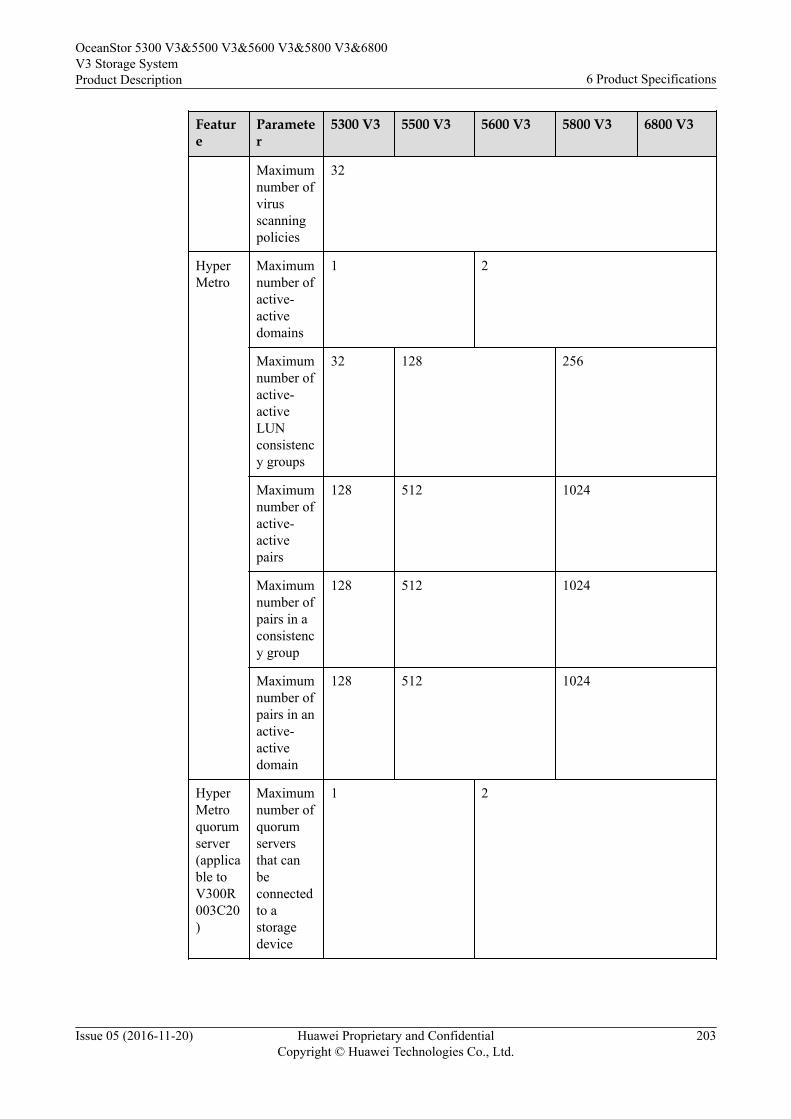
Feature
Parameter
5300 V3 5500 V3 5600 V3 5800 V3 6800 V3
Maximumnumber ofvirusscanningpolicies
32
HyperMetro
Maximumnumber ofactive-activedomains
1 2
Maximumnumber ofactive-activeLUNconsistency groups
32 128 256
Maximumnumber ofactive-activepairs
128 512 1024
Maximumnumber ofpairs in aconsistency group
128 512 1024
Maximumnumber ofpairs in anactive-activedomain
128 512 1024
HyperMetroquorumserver(applicable toV300R003C20)
Maximumnumber ofquorumserversthat canbeconnectedto astoragedevice
1 2
OceanStor 5300 V3&5500 V3&5600 V3&5800 V3&6800V3 Storage SystemProduct Description 6 Product Specifications
Issue 05 (2016-11-20) Huawei Proprietary and ConfidentialCopyright © Huawei Technologies Co., Ltd.
203
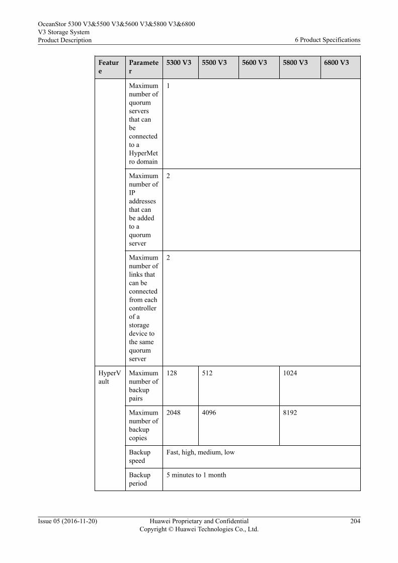
Feature
Parameter
5300 V3 5500 V3 5600 V3 5800 V3 6800 V3
Maximumnumber ofquorumserversthat canbeconnectedto aHyperMetro domain
1
Maximumnumber ofIPaddressesthat canbe addedto aquorumserver
2
Maximumnumber oflinks thatcan beconnectedfrom eachcontrollerof astoragedevice tothe samequorumserver
2
HyperVault
Maximumnumber ofbackuppairs
128 512 1024
Maximumnumber ofbackupcopies
2048 4096 8192
Backupspeed
Fast, high, medium, low
Backupperiod
5 minutes to 1 month
OceanStor 5300 V3&5500 V3&5600 V3&5800 V3&6800V3 Storage SystemProduct Description 6 Product Specifications
Issue 05 (2016-11-20) Huawei Proprietary and ConfidentialCopyright © Huawei Technologies Co., Ltd.
204
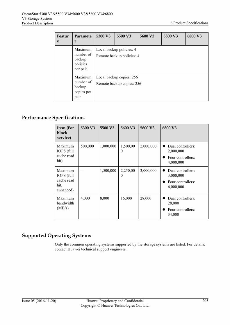
Feature
Parameter
5300 V3 5500 V3 5600 V3 5800 V3 6800 V3
Maximumnumber ofbackuppoliciesper pair
Local backup policies: 4Remote backup policies: 4
Maximumnumber ofbackupcopies perpair
Local backup copies: 256Remote backup copies: 256
Performance Specifications
Item (Forblockservice)
5300 V3 5500 V3 5600 V3 5800 V3 6800 V3
MaximumIOPS (fullcache readhit)
500,000 1,000,000 1,500,000
2,000,000 l Dual controllers:2,000,000
l Four controllers:4,000,000
MaximumIOPS (fullcache readhit,enhanced)
- 1,500,000 2,250,000
3,000,000 l Dual controllers:3,000,000
l Four controllers:6,000,000
Maximumbandwidth(MB/s)
4,000 8,000 16,000 28,000 l Dual controllers:28,000
l Four controllers:34,000
Supported Operating SystemsOnly the common operating systems supported by the storage systems are listed. For details,contact Huawei technical support engineers.
OceanStor 5300 V3&5500 V3&5600 V3&5800 V3&6800V3 Storage SystemProduct Description 6 Product Specifications
Issue 05 (2016-11-20) Huawei Proprietary and ConfidentialCopyright © Huawei Technologies Co., Ltd.
205
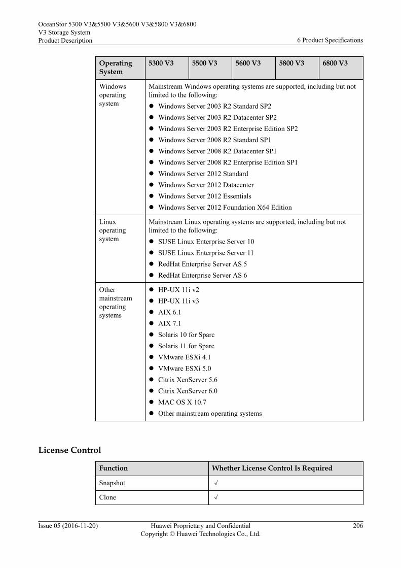
OperatingSystem
5300 V3 5500 V3 5600 V3 5800 V3 6800 V3
Windowsoperatingsystem
Mainstream Windows operating systems are supported, including but notlimited to the following:l Windows Server 2003 R2 Standard SP2l Windows Server 2003 R2 Datacenter SP2l Windows Server 2003 R2 Enterprise Edition SP2l Windows Server 2008 R2 Standard SP1l Windows Server 2008 R2 Datacenter SP1l Windows Server 2008 R2 Enterprise Edition SP1l Windows Server 2012 Standardl Windows Server 2012 Datacenterl Windows Server 2012 Essentialsl Windows Server 2012 Foundation X64 Edition
Linuxoperatingsystem
Mainstream Linux operating systems are supported, including but notlimited to the following:l SUSE Linux Enterprise Server 10l SUSE Linux Enterprise Server 11l RedHat Enterprise Server AS 5l RedHat Enterprise Server AS 6
Othermainstreamoperatingsystems
l HP-UX 11i v2l HP-UX 11i v3l AIX 6.1l AIX 7.1l Solaris 10 for Sparcl Solaris 11 for Sparcl VMware ESXi 4.1l VMware ESXi 5.0l Citrix XenServer 5.6l Citrix XenServer 6.0l MAC OS X 10.7l Other mainstream operating systems
License Control
Function Whether License Control Is Required
Snapshot √
Clone √
OceanStor 5300 V3&5500 V3&5600 V3&5800 V3&6800V3 Storage SystemProduct Description 6 Product Specifications
Issue 05 (2016-11-20) Huawei Proprietary and ConfidentialCopyright © Huawei Technologies Co., Ltd.
206
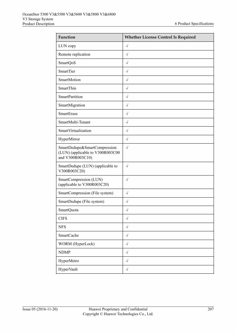
Function Whether License Control Is Required
LUN copy √
Remote replication √
SmartQoS √
SmartTier √
SmartMotion √
SmartThin √
SmartPartition √
SmartMigration √
SmartErase √
SmartMulti-Tenant √
SmartVirtualization √
HyperMirror √
SmartDedupe&SmartCompression(LUN) (applicable to V300R003C00and V300R003C10)
√
SmartDedupe (LUN) (applicable toV300R003C20)
√
SmartCompression (LUN)(applicable to V300R003C20)
√
SmartCompression (File system) √
SmartDedupe (File system) √
SmartQuota √
CIFS √
NFS √
SmartCache √
WORM (HyperLock) √
NDMP √
HyperMetro √
HyperVault √
OceanStor 5300 V3&5500 V3&5600 V3&5800 V3&6800V3 Storage SystemProduct Description 6 Product Specifications
Issue 05 (2016-11-20) Huawei Proprietary and ConfidentialCopyright © Huawei Technologies Co., Ltd.
207
NOTE
As the OceanStor SystemReporter and OceanStor UltraPath are not deployed on a storage system, youcannot check them on the license management page of the storage system. To view purchased features,you can obtain the product authorization certificate from your dealer, which shows the purchasedfeatures.
Interoperability and Host ConnectivityYou can obtain the documentation for the interoperability and host connectivity of the storagesystem in the following ways:l Interoperability Matrix: Log in to the HUAWEI enterprise website http://
enterprise.huawei.com, search Storage Interoperability Matrix, select the categoryCollateral, download the item corresponding to the current product in use.
l Host Connectivity Guide: Visit the HUAWEI enterprise support website http://support.huawei.com/enterprise and search Host Connectivity Guide.
OceanStor 5300 V3&5500 V3&5600 V3&5800 V3&6800V3 Storage SystemProduct Description 6 Product Specifications
Issue 05 (2016-11-20) Huawei Proprietary and ConfidentialCopyright © Huawei Technologies Co., Ltd.
208
7 Environmental Requirements
About This Chapter
Environmental requirements cover the following aspects: temperature, humidity, particlecontaminants, corrosive airborne contaminants, heat dissipation, and noise.
7.1 Temperature, Humidity, and AltitudeTemperature, humidity, and altitude requirements must be met so that storage systems cancorrectly work or be properly preserved.
7.2 Vibration and ShockVibration and shock requirements must be met so that storage systems can correctly work orbe properly preserved.
7.3 Particle ContaminantsParticle contaminants and other negative environmental factors (such as abnormaltemperature and humidity) may expose IT equipment to a higher risks of corrosive failure.This clause specifies the limitation on particle contaminants with the aim at avoiding suchrisks.
7.4 Corrosive Airborne ContaminantsCorrosive airborne contaminants and other negative environmental factors (such as abnormaltemperature and humidity) may expose IT equipment to higher risks of corrosive failure. Thisarticle specifies the limitation on corrosive airborne contaminants with an aim at avoidingsuch risks.
7.5 Heat Dissipation and NoiseA storage system can run steadily using the heat dissipation system carried in its own fanmodules. An external device is necessary to remove the hot air discharged from a storagesystem into the equipment room to ensure proper air circulation.
OceanStor 5300 V3&5500 V3&5600 V3&5800 V3&6800V3 Storage SystemProduct Description 7 Environmental Requirements
Issue 05 (2016-11-20) Huawei Proprietary and ConfidentialCopyright © Huawei Technologies Co., Ltd.
209
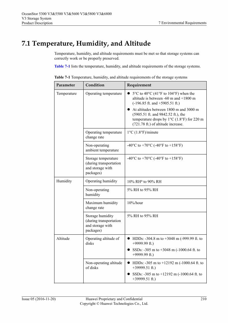
7.1 Temperature, Humidity, and AltitudeTemperature, humidity, and altitude requirements must be met so that storage systems cancorrectly work or be properly preserved.
Table 7-1 lists the temperature, humidity, and altitude requirements of the storage systems.
Table 7-1 Temperature, humidity, and altitude requirements of the storage systems
Parameter Condition Requirement
Temperature Operating temperature l 5°C to 40°C (41°F to 104°F) when thealtitude is between -60 m and +1800 m(-196.85 ft. and +5905.51 ft.)
l At altitudes between 1800 m and 3000 m(5905.51 ft. and 9842.52 ft.), thetemperature drops by 1°C (1.8°F) for 220 m(721.78 ft.) of altitude increase.
Operating temperaturechange rate
1°C (1.8°F)/minute
Non-operatingambient temperature
-40°C to +70°C (-40°F to +158°F)
Storage temperature(during transportationand storage withpackages)
-40°C to +70°C (-40°F to +158°F)
Humidity Operating humidity 10% RHa to 90% RH
Non-operatinghumidity
5% RH to 95% RH
Maximum humiditychange rate
10%/hour
Storage humidity(during transportationand storage withpackages)
5% RH to 95% RH
Altitude Operating altitude ofdisks
l HDDs: -304.8 m to +3048 m (-999.99 ft. to+9999.99 ft.)
l SSDs: -305 m to +3048 m (-1000.64 ft. to+9999.99 ft.)
Non-operating altitudeof disks
l HDDs: -305 m to +12192 m (-1000.64 ft. to+39999.51 ft.)
l SSDs: -305 m to +12192 m (-1000.64 ft. to+39999.51 ft.)
OceanStor 5300 V3&5500 V3&5600 V3&5800 V3&6800V3 Storage SystemProduct Description 7 Environmental Requirements
Issue 05 (2016-11-20) Huawei Proprietary and ConfidentialCopyright © Huawei Technologies Co., Ltd.
210
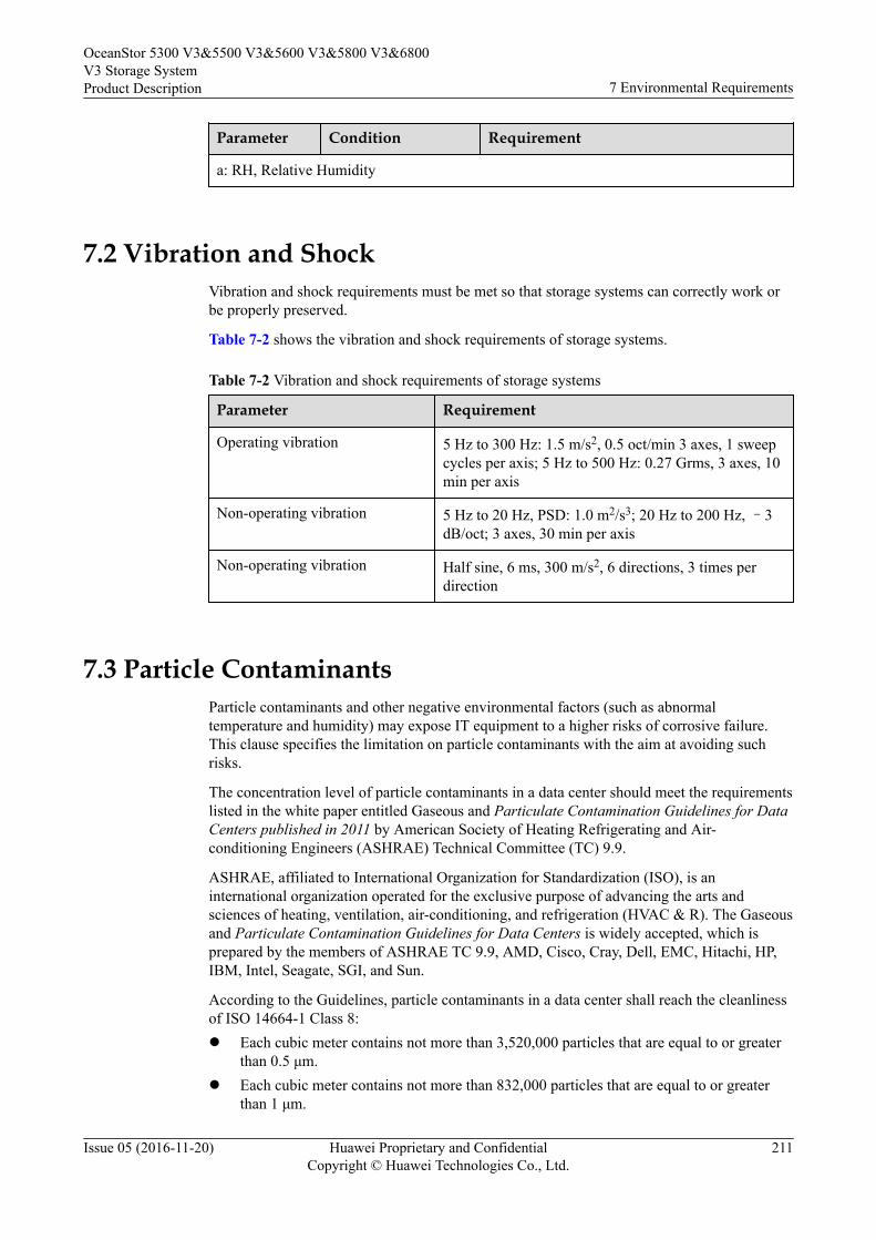
Parameter Condition Requirement
a: RH, Relative Humidity
7.2 Vibration and ShockVibration and shock requirements must be met so that storage systems can correctly work orbe properly preserved.
Table 7-2 shows the vibration and shock requirements of storage systems.
Table 7-2 Vibration and shock requirements of storage systems
Parameter Requirement
Operating vibration 5 Hz to 300 Hz: 1.5 m/s2, 0.5 oct/min 3 axes, 1 sweepcycles per axis; 5 Hz to 500 Hz: 0.27 Grms, 3 axes, 10min per axis
Non-operating vibration 5 Hz to 20 Hz, PSD: 1.0 m2/s3; 20 Hz to 200 Hz, –3dB/oct; 3 axes, 30 min per axis
Non-operating vibration Half sine, 6 ms, 300 m/s2, 6 directions, 3 times perdirection
7.3 Particle ContaminantsParticle contaminants and other negative environmental factors (such as abnormaltemperature and humidity) may expose IT equipment to a higher risks of corrosive failure.This clause specifies the limitation on particle contaminants with the aim at avoiding suchrisks.
The concentration level of particle contaminants in a data center should meet the requirementslisted in the white paper entitled Gaseous and Particulate Contamination Guidelines for DataCenters published in 2011 by American Society of Heating Refrigerating and Air-conditioning Engineers (ASHRAE) Technical Committee (TC) 9.9.
ASHRAE, affiliated to International Organization for Standardization (ISO), is aninternational organization operated for the exclusive purpose of advancing the arts andsciences of heating, ventilation, air-conditioning, and refrigeration (HVAC & R). The Gaseousand Particulate Contamination Guidelines for Data Centers is widely accepted, which isprepared by the members of ASHRAE TC 9.9, AMD, Cisco, Cray, Dell, EMC, Hitachi, HP,IBM, Intel, Seagate, SGI, and Sun.
According to the Guidelines, particle contaminants in a data center shall reach the cleanlinessof ISO 14664-1 Class 8:l Each cubic meter contains not more than 3,520,000 particles that are equal to or greater
than 0.5 μm.l Each cubic meter contains not more than 832,000 particles that are equal to or greater
than 1 μm.
OceanStor 5300 V3&5500 V3&5600 V3&5800 V3&6800V3 Storage SystemProduct Description 7 Environmental Requirements
Issue 05 (2016-11-20) Huawei Proprietary and ConfidentialCopyright © Huawei Technologies Co., Ltd.
211
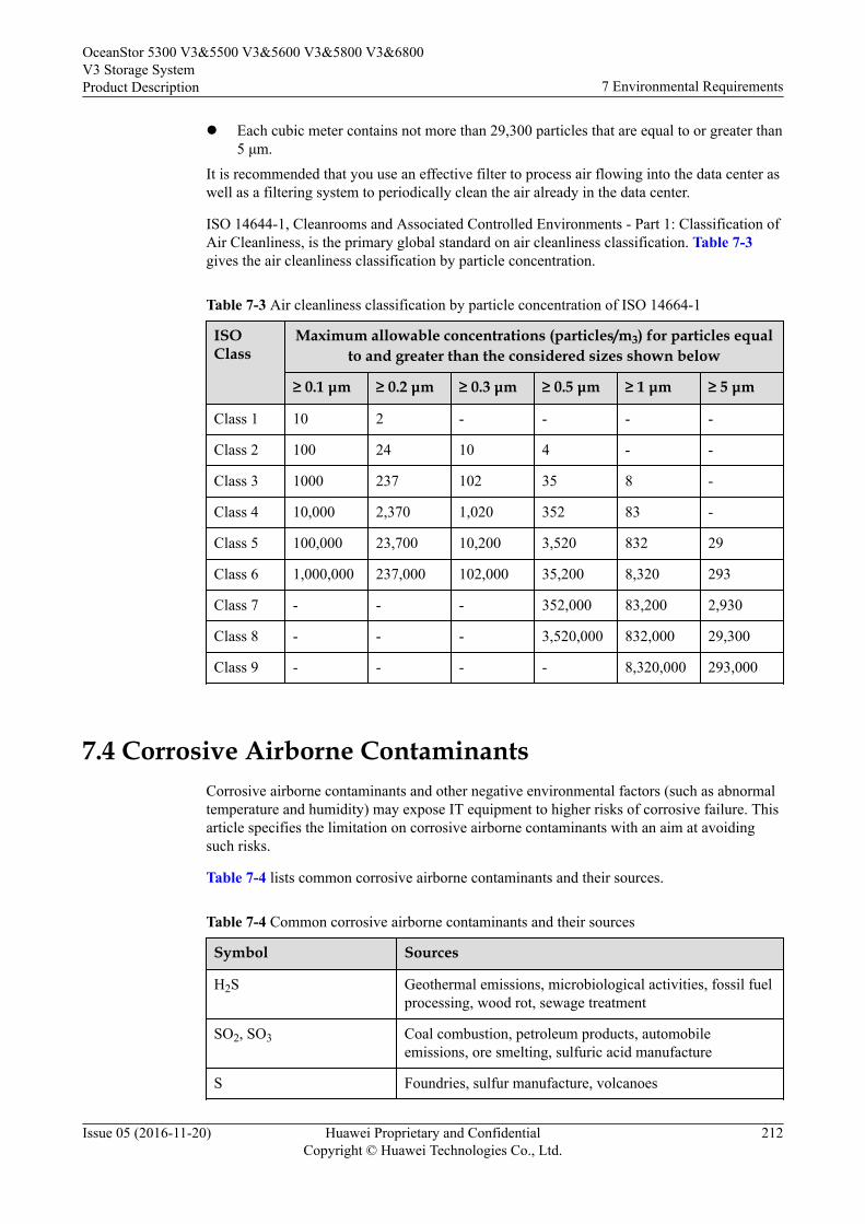
l Each cubic meter contains not more than 29,300 particles that are equal to or greater than5 μm.
It is recommended that you use an effective filter to process air flowing into the data center aswell as a filtering system to periodically clean the air already in the data center.
ISO 14644-1, Cleanrooms and Associated Controlled Environments - Part 1: Classification ofAir Cleanliness, is the primary global standard on air cleanliness classification. Table 7-3gives the air cleanliness classification by particle concentration.
Table 7-3 Air cleanliness classification by particle concentration of ISO 14664-1
ISOClass
Maximum allowable concentrations (particles/m3) for particles equalto and greater than the considered sizes shown below
≥ 0.1 μm ≥ 0.2 μm ≥ 0.3 μm ≥ 0.5 μm ≥ 1 μm ≥ 5 μm
Class 1 10 2 - - - -
Class 2 100 24 10 4 - -
Class 3 1000 237 102 35 8 -
Class 4 10,000 2,370 1,020 352 83 -
Class 5 100,000 23,700 10,200 3,520 832 29
Class 6 1,000,000 237,000 102,000 35,200 8,320 293
Class 7 - - - 352,000 83,200 2,930
Class 8 - - - 3,520,000 832,000 29,300
Class 9 - - - - 8,320,000 293,000
7.4 Corrosive Airborne ContaminantsCorrosive airborne contaminants and other negative environmental factors (such as abnormaltemperature and humidity) may expose IT equipment to higher risks of corrosive failure. Thisarticle specifies the limitation on corrosive airborne contaminants with an aim at avoidingsuch risks.
Table 7-4 lists common corrosive airborne contaminants and their sources.
Table 7-4 Common corrosive airborne contaminants and their sources
Symbol Sources
H2S Geothermal emissions, microbiological activities, fossil fuelprocessing, wood rot, sewage treatment
SO2, SO3 Coal combustion, petroleum products, automobileemissions, ore smelting, sulfuric acid manufacture
S Foundries, sulfur manufacture, volcanoes
OceanStor 5300 V3&5500 V3&5600 V3&5800 V3&6800V3 Storage SystemProduct Description 7 Environmental Requirements
Issue 05 (2016-11-20) Huawei Proprietary and ConfidentialCopyright © Huawei Technologies Co., Ltd.
212
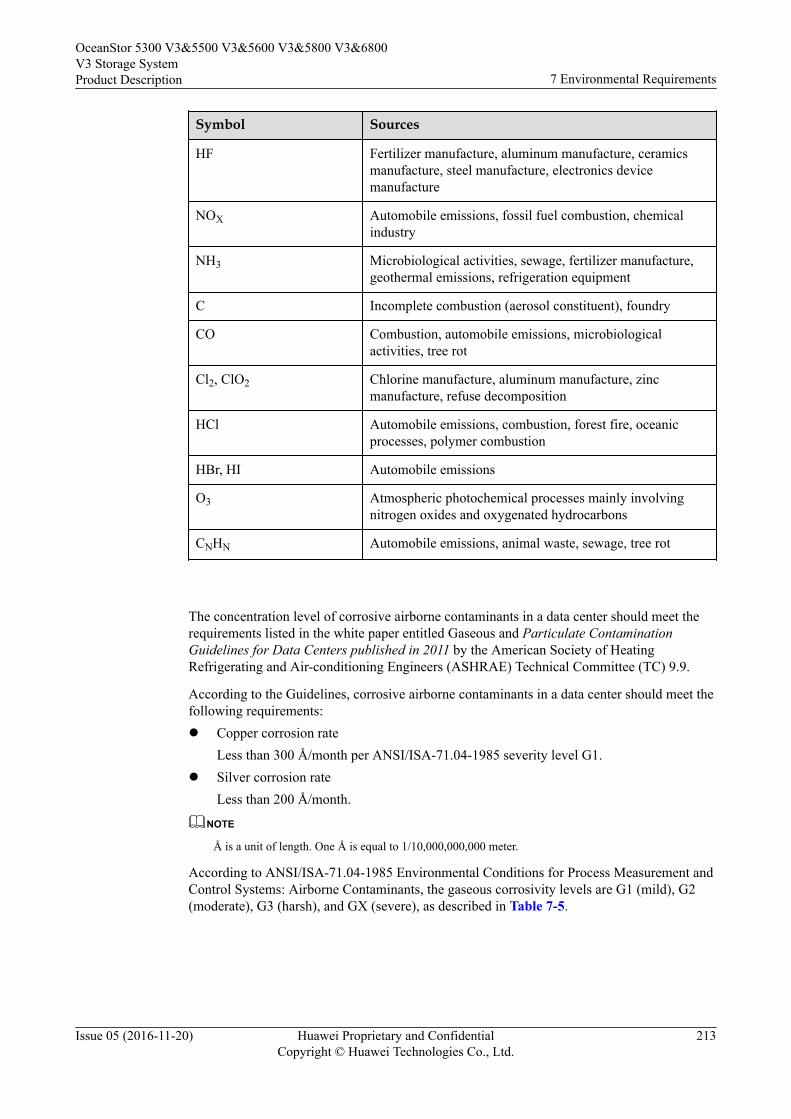
Symbol Sources
HF Fertilizer manufacture, aluminum manufacture, ceramicsmanufacture, steel manufacture, electronics devicemanufacture
NOX Automobile emissions, fossil fuel combustion, chemicalindustry
NH3 Microbiological activities, sewage, fertilizer manufacture,geothermal emissions, refrigeration equipment
C Incomplete combustion (aerosol constituent), foundry
CO Combustion, automobile emissions, microbiologicalactivities, tree rot
Cl2, ClO2 Chlorine manufacture, aluminum manufacture, zincmanufacture, refuse decomposition
HCl Automobile emissions, combustion, forest fire, oceanicprocesses, polymer combustion
HBr, HI Automobile emissions
O3 Atmospheric photochemical processes mainly involvingnitrogen oxides and oxygenated hydrocarbons
CNHN Automobile emissions, animal waste, sewage, tree rot
The concentration level of corrosive airborne contaminants in a data center should meet therequirements listed in the white paper entitled Gaseous and Particulate ContaminationGuidelines for Data Centers published in 2011 by the American Society of HeatingRefrigerating and Air-conditioning Engineers (ASHRAE) Technical Committee (TC) 9.9.
According to the Guidelines, corrosive airborne contaminants in a data center should meet thefollowing requirements:l Copper corrosion rate
Less than 300 Å/month per ANSI/ISA-71.04-1985 severity level G1.l Silver corrosion rate
Less than 200 Å/month.
NOTE
Å is a unit of length. One Å is equal to 1/10,000,000,000 meter.
According to ANSI/ISA-71.04-1985 Environmental Conditions for Process Measurement andControl Systems: Airborne Contaminants, the gaseous corrosivity levels are G1 (mild), G2(moderate), G3 (harsh), and GX (severe), as described in Table 7-5.
OceanStor 5300 V3&5500 V3&5600 V3&5800 V3&6800V3 Storage SystemProduct Description 7 Environmental Requirements
Issue 05 (2016-11-20) Huawei Proprietary and ConfidentialCopyright © Huawei Technologies Co., Ltd.
213
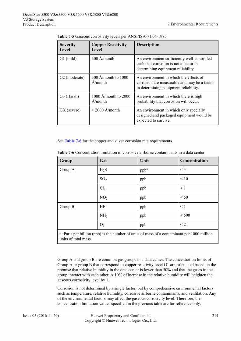
Table 7-5 Gaseous corrosivity levels per ANSI/ISA-71.04-1985
SeverityLevel
Copper ReactivityLevel
Description
G1 (mild) 300 Å/month An environment sufficiently well-controlledsuch that corrosion is not a factor indetermining equipment reliability.
G2 (moderate) 300 Å/month to 1000Å/month
An environment in which the effects ofcorrosion are measurable and may be a factorin determining equipment reliability.
G3 (Harsh) 1000 Å/month to 2000Å/month
An environment in which there is highprobability that corrosion will occur.
GX (severe) > 2000 Å/month An environment in which only speciallydesigned and packaged equipment would beexpected to survive.
See Table 7-6 for the copper and silver corrosion rate requirements.
Table 7-6 Concentration limitation of corrosive airborne contaminants in a data center
Group Gas Unit Concentration
Group A H2S ppba < 3
SO2 ppb < 10
Cl2 ppb < 1
NO2 ppb < 50
Group B HF ppb < 1
NH3 ppb < 500
O3 ppb < 2
a: Parts per billion (ppb) is the number of units of mass of a contaminant per 1000 millionunits of total mass.
Group A and group B are common gas groups in a data center. The concentration limits ofGroup A or group B that correspond to copper reactivity level G1 are calculated based on thepremise that relative humidity in the data center is lower than 50% and that the gases in thegroup interact with each other. A 10% of increase in the relative humidity will heighten thegaseous corrosivity level by 1.
Corrosion is not determined by a single factor, but by comprehensive environmental factorssuch as temperature, relative humidity, corrosive airborne contaminants, and ventilation. Anyof the environmental factors may affect the gaseous corrosivity level. Therefore, theconcentration limitation values specified in the previous table are for reference only.
OceanStor 5300 V3&5500 V3&5600 V3&5800 V3&6800V3 Storage SystemProduct Description 7 Environmental Requirements
Issue 05 (2016-11-20) Huawei Proprietary and ConfidentialCopyright © Huawei Technologies Co., Ltd.
214
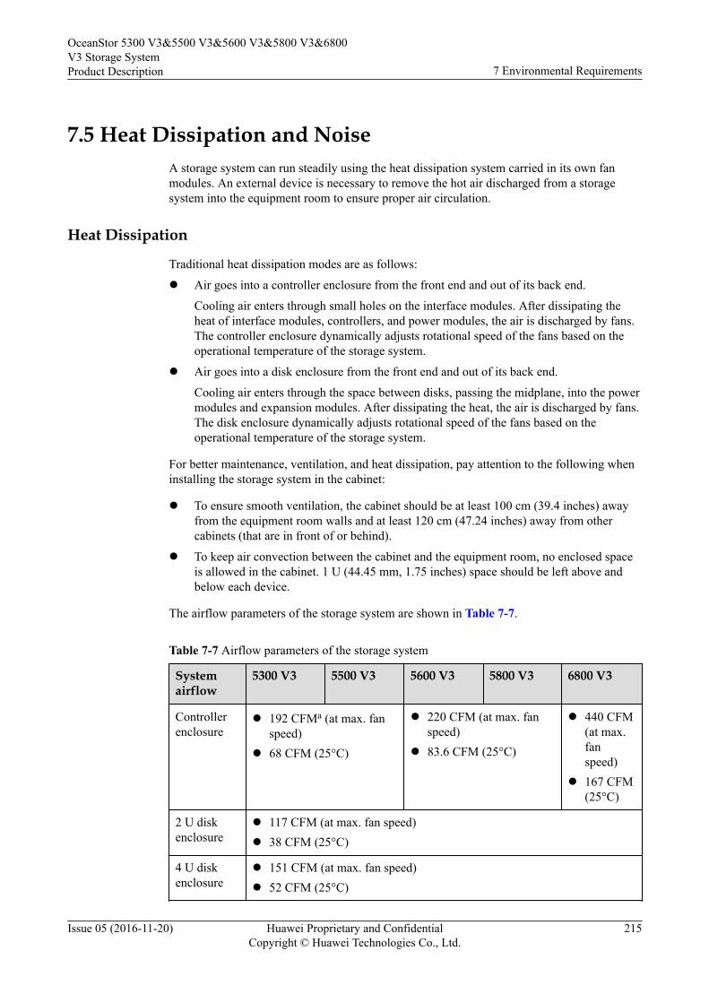
7.5 Heat Dissipation and NoiseA storage system can run steadily using the heat dissipation system carried in its own fanmodules. An external device is necessary to remove the hot air discharged from a storagesystem into the equipment room to ensure proper air circulation.
Heat Dissipation
Traditional heat dissipation modes are as follows:
l Air goes into a controller enclosure from the front end and out of its back end.
Cooling air enters through small holes on the interface modules. After dissipating theheat of interface modules, controllers, and power modules, the air is discharged by fans.The controller enclosure dynamically adjusts rotational speed of the fans based on theoperational temperature of the storage system.
l Air goes into a disk enclosure from the front end and out of its back end.
Cooling air enters through the space between disks, passing the midplane, into the powermodules and expansion modules. After dissipating the heat, the air is discharged by fans.The disk enclosure dynamically adjusts rotational speed of the fans based on theoperational temperature of the storage system.
For better maintenance, ventilation, and heat dissipation, pay attention to the following wheninstalling the storage system in the cabinet:
l To ensure smooth ventilation, the cabinet should be at least 100 cm (39.4 inches) awayfrom the equipment room walls and at least 120 cm (47.24 inches) away from othercabinets (that are in front of or behind).
l To keep air convection between the cabinet and the equipment room, no enclosed spaceis allowed in the cabinet. 1 U (44.45 mm, 1.75 inches) space should be left above andbelow each device.
The airflow parameters of the storage system are shown in Table 7-7.
Table 7-7 Airflow parameters of the storage system
Systemairflow
5300 V3 5500 V3 5600 V3 5800 V3 6800 V3
Controllerenclosure
l 192 CFMa (at max. fanspeed)
l 68 CFM (25°C)
l 220 CFM (at max. fanspeed)
l 83.6 CFM (25°C)
l 440 CFM(at max.fanspeed)
l 167 CFM(25°C)
2 U diskenclosure
l 117 CFM (at max. fan speed)l 38 CFM (25°C)
4 U diskenclosure
l 151 CFM (at max. fan speed)l 52 CFM (25°C)
OceanStor 5300 V3&5500 V3&5600 V3&5800 V3&6800V3 Storage SystemProduct Description 7 Environmental Requirements
Issue 05 (2016-11-20) Huawei Proprietary and ConfidentialCopyright © Huawei Technologies Co., Ltd.
215
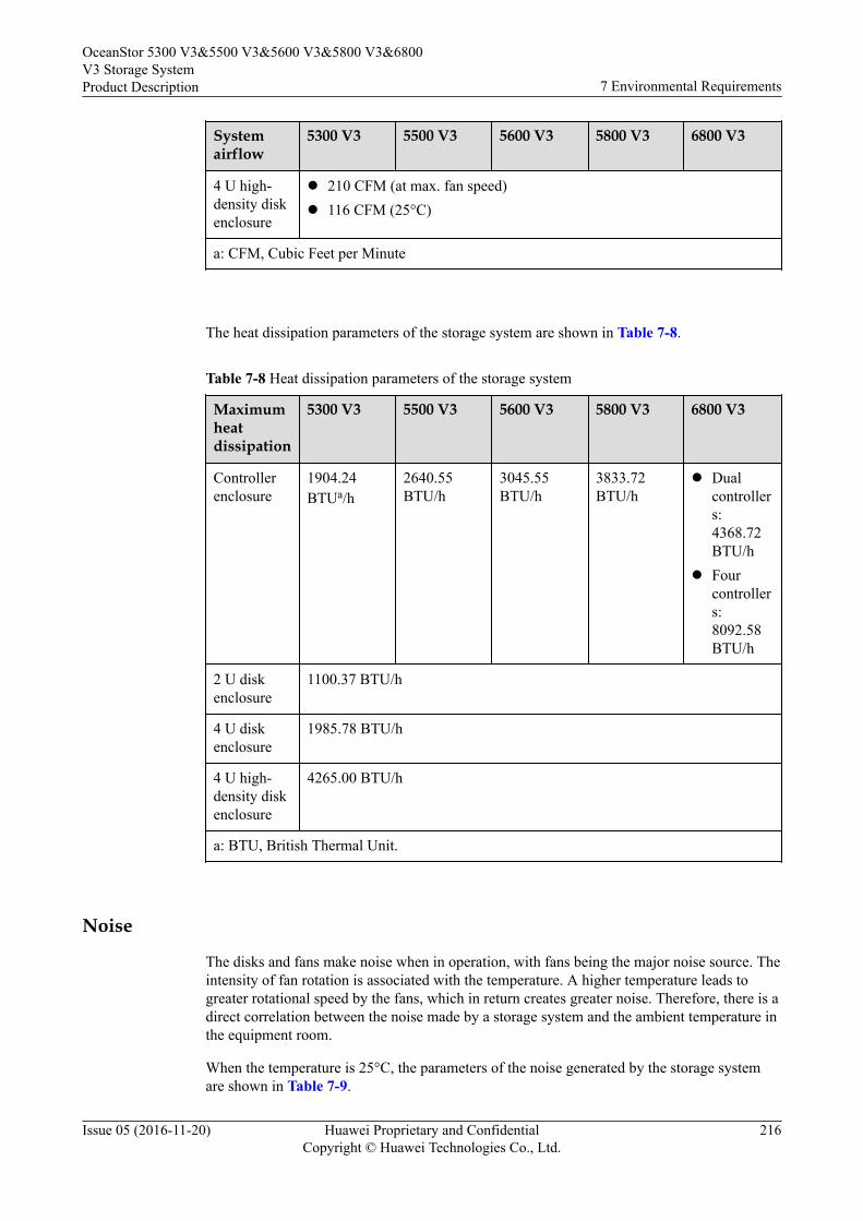
Systemairflow
5300 V3 5500 V3 5600 V3 5800 V3 6800 V3
4 U high-density diskenclosure
l 210 CFM (at max. fan speed)l 116 CFM (25°C)
a: CFM, Cubic Feet per Minute
The heat dissipation parameters of the storage system are shown in Table 7-8.
Table 7-8 Heat dissipation parameters of the storage system
Maximumheatdissipation
5300 V3 5500 V3 5600 V3 5800 V3 6800 V3
Controllerenclosure
1904.24BTUa/h
2640.55BTU/h
3045.55BTU/h
3833.72BTU/h
l Dualcontrollers:4368.72BTU/h
l Fourcontrollers:8092.58BTU/h
2 U diskenclosure
1100.37 BTU/h
4 U diskenclosure
1985.78 BTU/h
4 U high-density diskenclosure
4265.00 BTU/h
a: BTU, British Thermal Unit.
Noise
The disks and fans make noise when in operation, with fans being the major noise source. Theintensity of fan rotation is associated with the temperature. A higher temperature leads togreater rotational speed by the fans, which in return creates greater noise. Therefore, there is adirect correlation between the noise made by a storage system and the ambient temperature inthe equipment room.
When the temperature is 25°C, the parameters of the noise generated by the storage systemare shown in Table 7-9.
OceanStor 5300 V3&5500 V3&5600 V3&5800 V3&6800V3 Storage SystemProduct Description 7 Environmental Requirements
Issue 05 (2016-11-20) Huawei Proprietary and ConfidentialCopyright © Huawei Technologies Co., Ltd.
216
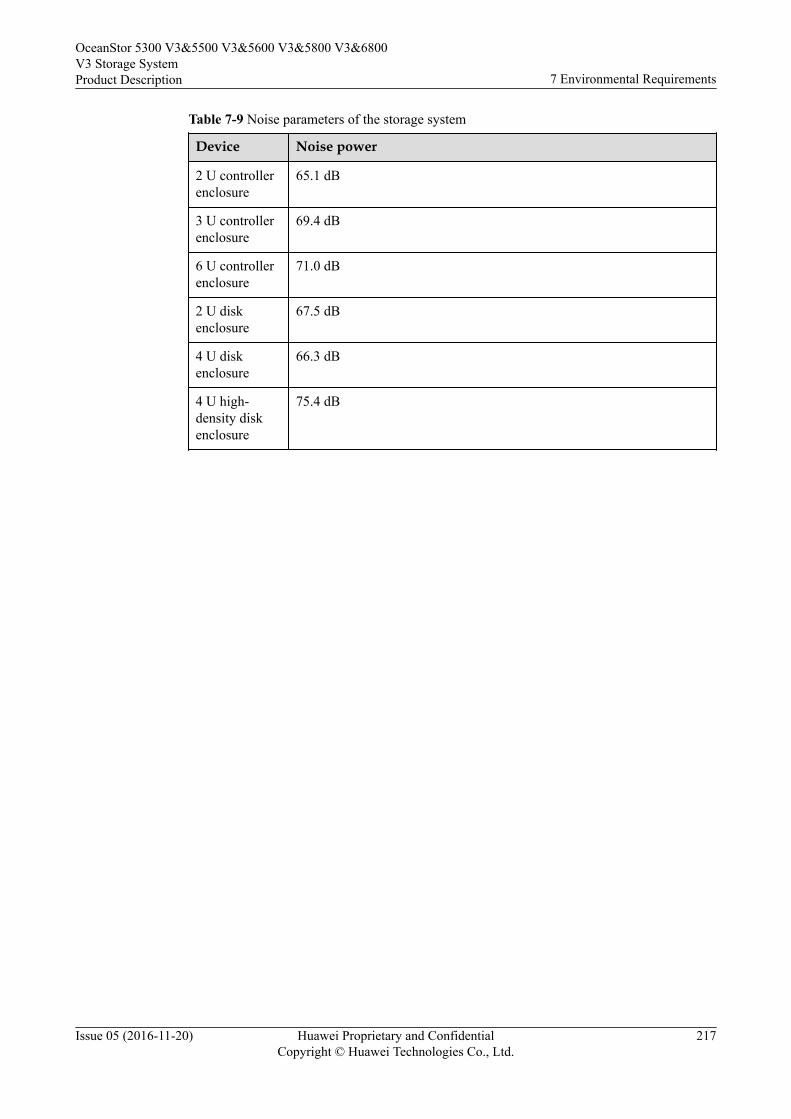
Table 7-9 Noise parameters of the storage system
Device Noise power
2 U controllerenclosure
65.1 dB
3 U controllerenclosure
69.4 dB
6 U controllerenclosure
71.0 dB
2 U diskenclosure
67.5 dB
4 U diskenclosure
66.3 dB
4 U high-density diskenclosure
75.4 dB
OceanStor 5300 V3&5500 V3&5600 V3&5800 V3&6800V3 Storage SystemProduct Description 7 Environmental Requirements
Issue 05 (2016-11-20) Huawei Proprietary and ConfidentialCopyright © Huawei Technologies Co., Ltd.
217
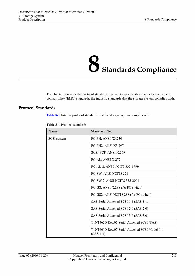
8 Standards Compliance
The chapter describes the protocol standards, the safety specifications and electromagneticcompatibility (EMC) standards, the industry standards that the storage system complies with.
Protocol StandardsTable 8-1 lists the protocol standards that the storage system complies with.
Table 8-1 Protocol standards
Name Standard No.
SCSI system FC-PH: ANSI X3.230
FC-PH2: ANSI X3.297
SCSI-FCP: ANSI X.269
FC-AL: ANSI X.272
FC-AL-2: ANSI NCITS 332-1999
FC-SW: ANSI NCITS 321
FC-SW-2: ANSI NCITS 355-2001
FC-GS: ANSI X.288 (for FC switch)
FC-GS2: ANSI NCITS 288 (for FC switch)
SAS Serial Attached SCSI-1.1 (SAS-1.1)
SAS Serial Attached SCSI-2.0 (SAS-2.0)
SAS Serial Attached SCSI-3.0 (SAS-3.0)
T10/1562D Rev.05 Serial Attached SCSI (SAS)
T10/1601D Rev.07 Serial Attached SCSI Model-1.1(SAS-1.1)
OceanStor 5300 V3&5500 V3&5600 V3&5800 V3&6800V3 Storage SystemProduct Description 8 Standards Compliance
Issue 05 (2016-11-20) Huawei Proprietary and ConfidentialCopyright © Huawei Technologies Co., Ltd.
218
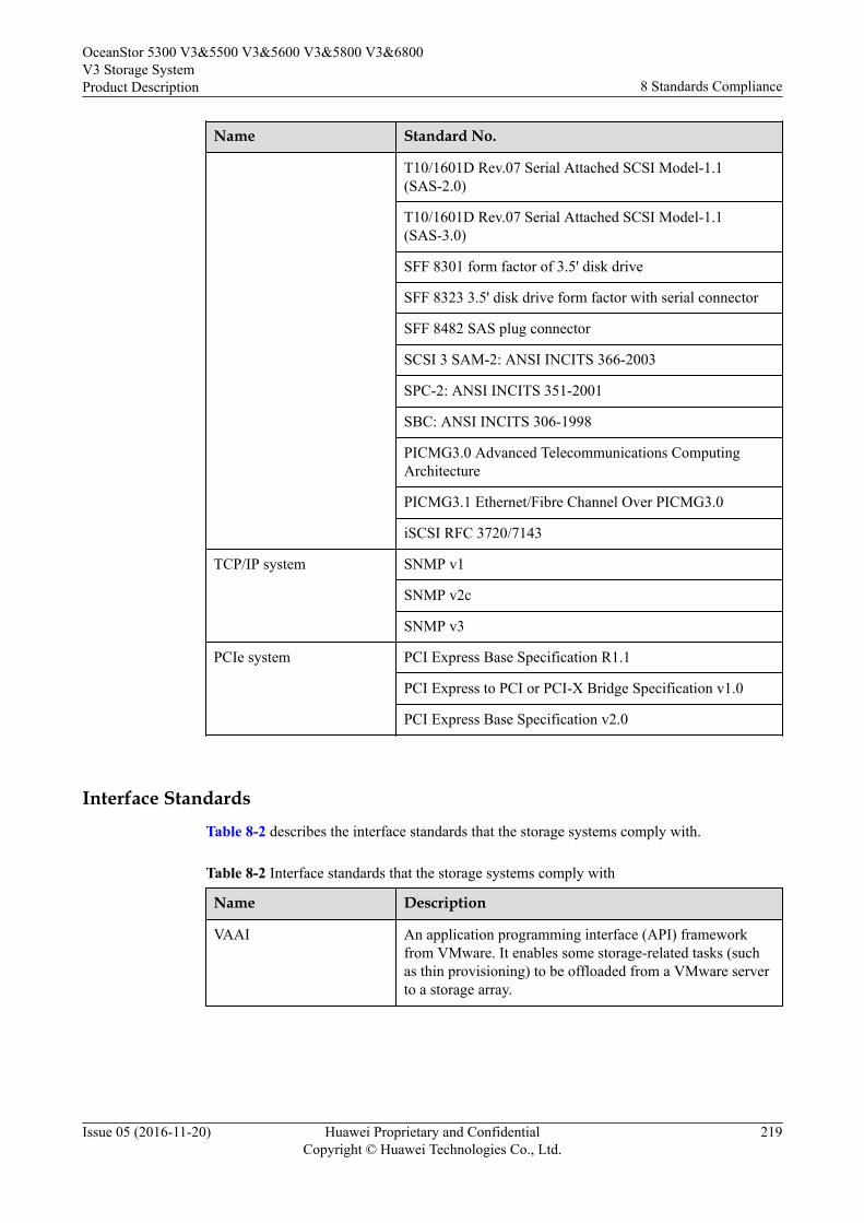
Name Standard No.
T10/1601D Rev.07 Serial Attached SCSI Model-1.1(SAS-2.0)
T10/1601D Rev.07 Serial Attached SCSI Model-1.1(SAS-3.0)
SFF 8301 form factor of 3.5' disk drive
SFF 8323 3.5' disk drive form factor with serial connector
SFF 8482 SAS plug connector
SCSI 3 SAM-2: ANSI INCITS 366-2003
SPC-2: ANSI INCITS 351-2001
SBC: ANSI INCITS 306-1998
PICMG3.0 Advanced Telecommunications ComputingArchitecture
PICMG3.1 Ethernet/Fibre Channel Over PICMG3.0
iSCSI RFC 3720/7143
TCP/IP system SNMP v1
SNMP v2c
SNMP v3
PCIe system PCI Express Base Specification R1.1
PCI Express to PCI or PCI-X Bridge Specification v1.0
PCI Express Base Specification v2.0
Interface StandardsTable 8-2 describes the interface standards that the storage systems comply with.
Table 8-2 Interface standards that the storage systems comply with
Name Description
VAAI An application programming interface (API) frameworkfrom VMware. It enables some storage-related tasks (suchas thin provisioning) to be offloaded from a VMware serverto a storage array.
OceanStor 5300 V3&5500 V3&5600 V3&5800 V3&6800V3 Storage SystemProduct Description 8 Standards Compliance
Issue 05 (2016-11-20) Huawei Proprietary and ConfidentialCopyright © Huawei Technologies Co., Ltd.
219
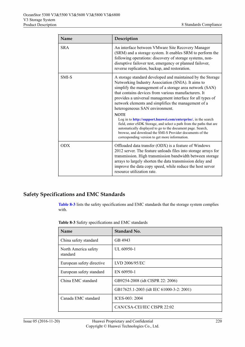
Name Description
SRA An interface between VMware Site Recovery Manager(SRM) and a storage system. It enables SRM to perform thefollowing operations: discovery of storage systems, non-disruptive failover test, emergency or planned failover,reverse replication, backup, and restoration.
SMI-S A storage standard developed and maintained by the StorageNetworking Industry Association (SNIA). It aims tosimplify the management of a storage area network (SAN)that contains devices from various manufacturers. Itprovides a universal management interface for all types ofnetwork elements and simplifies the management of aheterogeneous SAN environment.NOTE
Log in to http://support.huawei.com/enterprise/, in the searchfield, enter eSDK Storage, and select a path from the paths that areautomatically displayed to go to the document page. Search,browse, and download the SMI-S Provider documents of thecorresponding version to get more information.
ODX Offloaded data transfer (ODX) is a feature of Windows2012 server. The feature unloads files into storage arrays fortransmission. High transmission bandwidth between storagearrays to largely shorten the data transmission delay andimprove the data copy speed, while reduce the host serverresource utilization rate.
Safety Specifications and EMC Standards
Table 8-3 lists the safety specifications and EMC standards that the storage system complieswith.
Table 8-3 Safety specifications and EMC standards
Name Standard No.
China safety standard GB 4943
North America safetystandard
UL 60950-1
European safety directive LVD 2006/95/EC
European safety standard EN 60950-1
China EMC standard GB9254-2008 (idt CISPR 22: 2006)
GB17625.1-2003 (idt IEC 61000-3-2: 2001)
Canada EMC standard ICES-003: 2004
CAN/CSA-CEI/IEC CISPR 22:02
OceanStor 5300 V3&5500 V3&5600 V3&5800 V3&6800V3 Storage SystemProduct Description 8 Standards Compliance
Issue 05 (2016-11-20) Huawei Proprietary and ConfidentialCopyright © Huawei Technologies Co., Ltd.
220
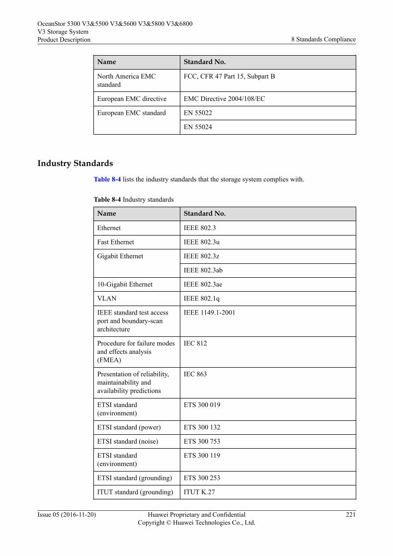
Name Standard No.
North America EMCstandard
FCC, CFR 47 Part 15, Subpart B
European EMC directive EMC Directive 2004/108/EC
European EMC standard EN 55022
EN 55024
Industry Standards
Table 8-4 lists the industry standards that the storage system complies with.
Table 8-4 Industry standards
Name Standard No.
Ethernet IEEE 802.3
Fast Ethernet IEEE 802.3u
Gigabit Ethernet IEEE 802.3z
IEEE 802.3ab
10-Gigabit Ethernet IEEE 802.3ae
VLAN IEEE 802.1q
IEEE standard test accessport and boundary-scanarchitecture
IEEE 1149.1-2001
Procedure for failure modesand effects analysis(FMEA)
IEC 812
Presentation of reliability,maintainability andavailability predictions
IEC 863
ETSI standard(environment)
ETS 300 019
ETSI standard (power) ETS 300 132
ETSI standard (noise) ETS 300 753
ETSI standard(environment)
ETS 300 119
ETSI standard (grounding) ETS 300 253
ITUT standard (grounding) ITUT K.27
OceanStor 5300 V3&5500 V3&5600 V3&5800 V3&6800V3 Storage SystemProduct Description 8 Standards Compliance
Issue 05 (2016-11-20) Huawei Proprietary and ConfidentialCopyright © Huawei Technologies Co., Ltd.
221
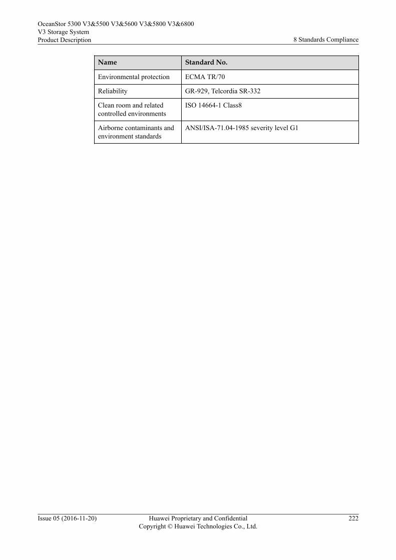
Name Standard No.
Environmental protection ECMA TR/70
Reliability GR-929, Telcordia SR-332
Clean room and relatedcontrolled environments
ISO 14664-1 Class8
Airborne contaminants andenvironment standards
ANSI/ISA-71.04-1985 severity level G1
OceanStor 5300 V3&5500 V3&5600 V3&5800 V3&6800V3 Storage SystemProduct Description 8 Standards Compliance
Issue 05 (2016-11-20) Huawei Proprietary and ConfidentialCopyright © Huawei Technologies Co., Ltd.
222
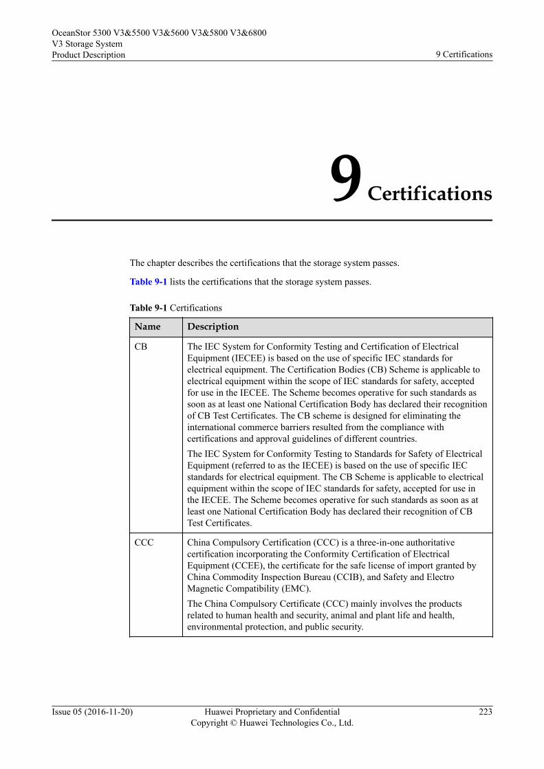
9 Certifications
The chapter describes the certifications that the storage system passes.
Table 9-1 lists the certifications that the storage system passes.
Table 9-1 Certifications
Name Description
CB The IEC System for Conformity Testing and Certification of ElectricalEquipment (IECEE) is based on the use of specific IEC standards forelectrical equipment. The Certification Bodies (CB) Scheme is applicable toelectrical equipment within the scope of IEC standards for safety, acceptedfor use in the IECEE. The Scheme becomes operative for such standards assoon as at least one National Certification Body has declared their recognitionof CB Test Certificates. The CB scheme is designed for eliminating theinternational commerce barriers resulted from the compliance withcertifications and approval guidelines of different countries.The IEC System for Conformity Testing to Standards for Safety of ElectricalEquipment (referred to as the IECEE) is based on the use of specific IECstandards for electrical equipment. The CB Scheme is applicable to electricalequipment within the scope of IEC standards for safety, accepted for use inthe IECEE. The Scheme becomes operative for such standards as soon as atleast one National Certification Body has declared their recognition of CBTest Certificates.
CCC China Compulsory Certification (CCC) is a three-in-one authoritativecertification incorporating the Conformity Certification of ElectricalEquipment (CCEE), the certificate for the safe license of import granted byChina Commodity Inspection Bureau (CCIB), and Safety and ElectroMagnetic Compatibility (EMC).The China Compulsory Certificate (CCC) mainly involves the productsrelated to human health and security, animal and plant life and health,environmental protection, and public security.
OceanStor 5300 V3&5500 V3&5600 V3&5800 V3&6800V3 Storage SystemProduct Description 9 Certifications
Issue 05 (2016-11-20) Huawei Proprietary and ConfidentialCopyright © Huawei Technologies Co., Ltd.
223
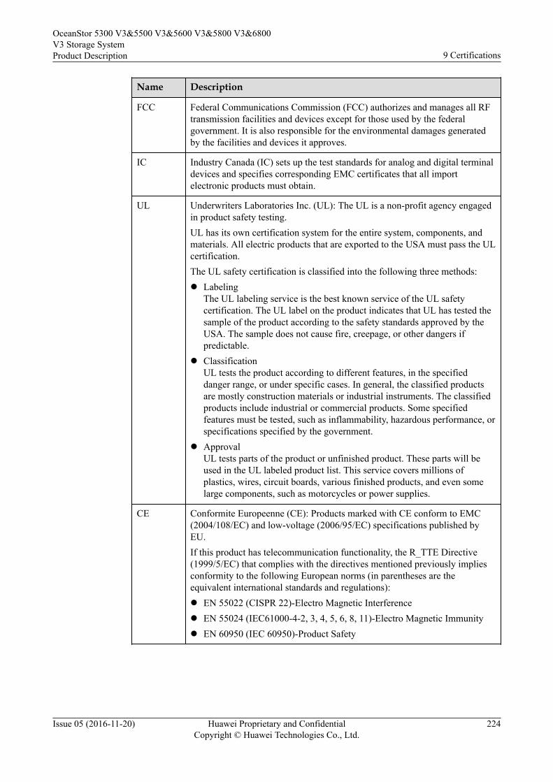
Name Description
FCC Federal Communications Commission (FCC) authorizes and manages all RFtransmission facilities and devices except for those used by the federalgovernment. It is also responsible for the environmental damages generatedby the facilities and devices it approves.
IC Industry Canada (IC) sets up the test standards for analog and digital terminaldevices and specifies corresponding EMC certificates that all importelectronic products must obtain.
UL Underwriters Laboratories Inc. (UL): The UL is a non-profit agency engagedin product safety testing.UL has its own certification system for the entire system, components, andmaterials. All electric products that are exported to the USA must pass the ULcertification.The UL safety certification is classified into the following three methods:l Labeling
The UL labeling service is the best known service of the UL safetycertification. The UL label on the product indicates that UL has tested thesample of the product according to the safety standards approved by theUSA. The sample does not cause fire, creepage, or other dangers ifpredictable.
l ClassificationUL tests the product according to different features, in the specifieddanger range, or under specific cases. In general, the classified productsare mostly construction materials or industrial instruments. The classifiedproducts include industrial or commercial products. Some specifiedfeatures must be tested, such as inflammability, hazardous performance, orspecifications specified by the government.
l ApprovalUL tests parts of the product or unfinished product. These parts will beused in the UL labeled product list. This service covers millions ofplastics, wires, circuit boards, various finished products, and even somelarge components, such as motorcycles or power supplies.
CE Conformite Europeenne (CE): Products marked with CE conform to EMC(2004/108/EC) and low-voltage (2006/95/EC) specifications published byEU.If this product has telecommunication functionality, the R_TTE Directive(1999/5/EC) that complies with the directives mentioned previously impliesconformity to the following European norms (in parentheses are theequivalent international standards and regulations):l EN 55022 (CISPR 22)-Electro Magnetic Interferencel EN 55024 (IEC61000-4-2, 3, 4, 5, 6, 8, 11)-Electro Magnetic Immunityl EN 60950 (IEC 60950)-Product Safety
OceanStor 5300 V3&5500 V3&5600 V3&5800 V3&6800V3 Storage SystemProduct Description 9 Certifications
Issue 05 (2016-11-20) Huawei Proprietary and ConfidentialCopyright © Huawei Technologies Co., Ltd.
224
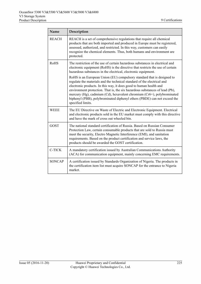
Name Description
REACH REACH is a set of comprehensive regulations that require all chemicalproducts that are both imported and produced in Europe must be registered,assessed, authorized, and restricted. In this way, customers can easilyrecognize the chemical elements. Thus, both humans and environment areprotected.
RoHS The restriction of the use of certain hazardous substances in electrical andelectronic equipment (RoHS) is the directive that restricts the use of certainhazardous substances in the electrical, electronic equipment.RoHS is an European Union (EU) compulsory standard that is designed toregulate the materials and the technical standard of the electrical andelectronic products. In this way, it does good to human health andenvironment protection. That is, the six hazardous substances of lead (Pb),mercury (Hg), cadmium (Cd), hexavalent chromium (Cr6+), polybrominatedbiphenyl (PBB), polybrominated diphenyl ethers (PBDE) can not exceed thespecified limits.
WEEE The EU Directive on Waste of Electric and Electronic Equipment. Electricaland electronic products sold in the EU market must comply with this directiveand have the mark of cross out wheeled bin.
GOST The national standard certification of Russia. Based on Russian ConsumerProtection Law, certain consumable products that are sold to Russia mustmeet the security, Electro Magnetic Interference (EMI), and sanitationrequirements. Based on the product certification and service laws, theproducts should be awarded the GOST certification.
C-TICK A mandatory certification issued by Australian Communications Authority(ACA) for communication equipment, mainly concerning EMC requirements.
SONCAP A certification issued by Standards Organization of Nigeria. The products inthe certification item list must acquire SONCAP for the entrance to Nigeriamarket.
OceanStor 5300 V3&5500 V3&5600 V3&5800 V3&6800V3 Storage SystemProduct Description 9 Certifications
Issue 05 (2016-11-20) Huawei Proprietary and ConfidentialCopyright © Huawei Technologies Co., Ltd.
225
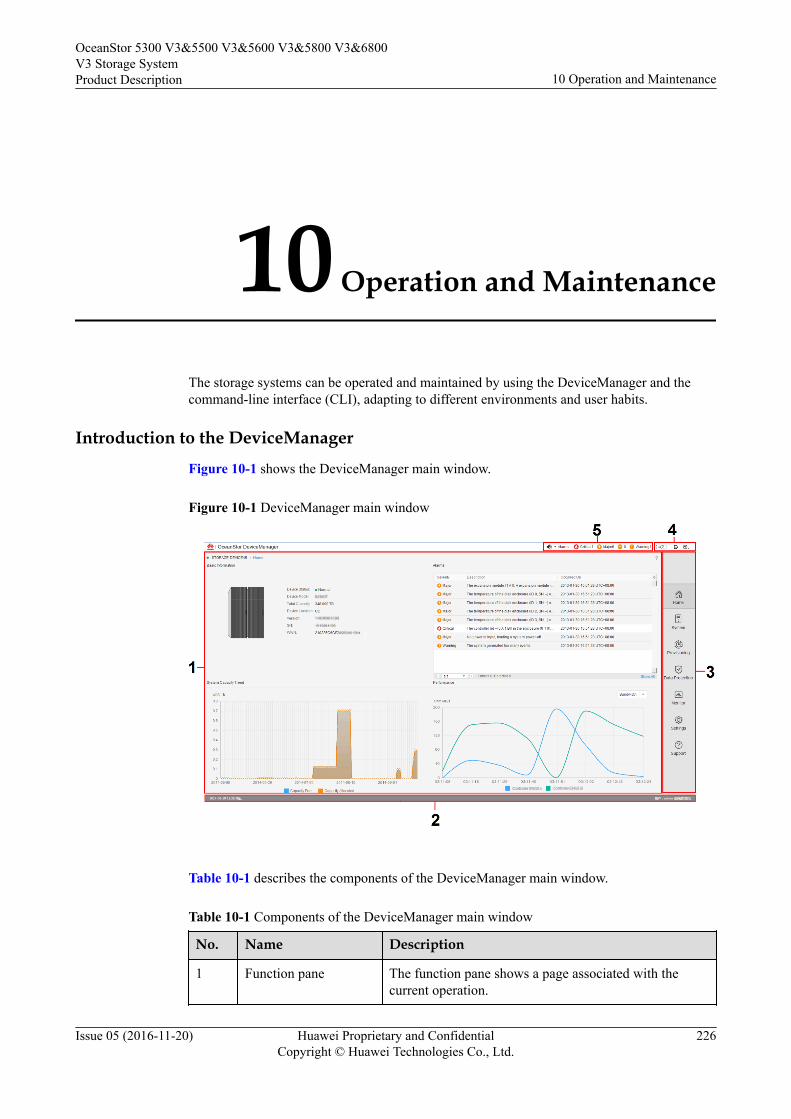
10 Operation and Maintenance
The storage systems can be operated and maintained by using the DeviceManager and thecommand-line interface (CLI), adapting to different environments and user habits.
Introduction to the DeviceManager
Figure 10-1 shows the DeviceManager main window.
Figure 10-1 DeviceManager main window
Table 10-1 describes the components of the DeviceManager main window.
Table 10-1 Components of the DeviceManager main window
No. Name Description
1 Function pane The function pane shows a page associated with thecurrent operation.
OceanStor 5300 V3&5500 V3&5600 V3&5800 V3&6800V3 Storage SystemProduct Description 10 Operation and Maintenance
Issue 05 (2016-11-20) Huawei Proprietary and ConfidentialCopyright © Huawei Technologies Co., Ltd.
226
No. Name Description
2 Status bar The status bar shows information such as the user namecurrently logged in and the login time.
3 Navigation bar The navigation bar shows the function modules of astorage system. Users can click a function module toconfigure the corresponding functions.
4 Exit, help, andlanguage selectionarea
This area displays an exit button, a help button, and alanguage selection button.
5 Fault statistics area The fault statistics area shows the number of each levelof system faults, helping users learn about the runningstatus of a storage system.
Users can log in to the DeviceManager by using a common browser.
Introduction to the CLIThe CLI enables users to manage and maintain the V3 series storage systems using commandlines.
Users need to log in to the CLI by using terminal software, such as the HyperTerminalprovided by Windows, or PuTTY.
There are two ways to log in to the CLI.l Log in through a serial port of a storage system. To connect to a serial port, the
maintenance terminal must be located next to the storage system. Therefore, this loginmode is applicable to the scenario where a user does not know the management IPaddress of a storage system or a storage system is faulty.
l Log in through a management network port of a storage system. When there arereachable routes, a user can log in to the CLI by entering the IP address of themanagement network port of a storage system in the terminal software. IP networks areeasily accessible. Therefore, a user can log in to a storage system remotely, and this loginmode is more popular.
OceanStor 5300 V3&5500 V3&5600 V3&5800 V3&6800V3 Storage SystemProduct Description 10 Operation and Maintenance
Issue 05 (2016-11-20) Huawei Proprietary and ConfidentialCopyright © Huawei Technologies Co., Ltd.
227
A How to Obtain Help
If a tough or critical problem persists in routine maintenance or troubleshooting, contactHuawei for technical support.
A.1 Preparations for Contacting HuaweiTo better solve the problem, you need to collect troubleshooting information and makedebugging preparations before contacting Huawei.
A.2 How to Use the DocumentHuawei provides guide documents shipped with the device. The guide documents can be usedto handle the common problems occurring in daily maintenance or troubleshooting.
A.3 How to Obtain Help from WebsiteHuawei provides users with timely and efficient technical support through the regionaloffices, secondary technical support system, telephone technical support, remote technicalsupport, and onsite technical support.
A.4 Ways to Contact HuaweiHuawei Technologies Co., Ltd. provides customers with comprehensive technical support andservice. For any assistance, contact our local office or company headquarters.
OceanStor 5300 V3&5500 V3&5600 V3&5800 V3&6800V3 Storage SystemProduct Description A How to Obtain Help
Issue 05 (2016-11-20) Huawei Proprietary and ConfidentialCopyright © Huawei Technologies Co., Ltd.
228
A.1 Preparations for Contacting HuaweiTo better solve the problem, you need to collect troubleshooting information and makedebugging preparations before contacting Huawei.
A.1.1 Collecting Troubleshooting InformationYou need to collect troubleshooting information before troubleshooting.
You need to collect the following information:l Name and address of the customerl Contact person and telephone numberl Time when the fault occurredl Description of the fault phenomenal Device type and software versionl Measures taken after the fault occurs and the related resultsl Troubleshooting level and required solution deadline
A.1.2 Making Debugging PreparationsWhen you contact Huawei for help, the technical support engineer of Huawei might assist youto do certain operations to collect information about the fault or rectify the fault directly.
Before contacting Huawei for help, you need to prepare the boards, port modules,screwdrivers, screws, cables for serial ports, network cables, and other required materials.
A.2 How to Use the DocumentHuawei provides guide documents shipped with the device. The guide documents can be usedto handle the common problems occurring in daily maintenance or troubleshooting.
To better solve the problems, use the documents before you contact Huawei for technicalsupport.
A.3 How to Obtain Help from WebsiteHuawei provides users with timely and efficient technical support through the regionaloffices, secondary technical support system, telephone technical support, remote technicalsupport, and onsite technical support.
Contents of the Huawei technical support system are as follows:l Huawei headquarters technical support departmentl Regional office technical support centerl Customer service centerl Technical support website: http://support.huawei.com/enterprise/
You can query how to contact the regional offices at http://support.huawei.com/enterprise/.
OceanStor 5300 V3&5500 V3&5600 V3&5800 V3&6800V3 Storage SystemProduct Description A How to Obtain Help
Issue 05 (2016-11-20) Huawei Proprietary and ConfidentialCopyright © Huawei Technologies Co., Ltd.
229
A.4 Ways to Contact HuaweiHuawei Technologies Co., Ltd. provides customers with comprehensive technical support andservice. For any assistance, contact our local office or company headquarters.
Huawei Technologies Co., Ltd.
Address: Huawei Industrial Base Bantian, Longgang Shenzhen 518129 People's Republic ofChina
Website: http://enterprise.huawei.com/
OceanStor 5300 V3&5500 V3&5600 V3&5800 V3&6800V3 Storage SystemProduct Description A How to Obtain Help
Issue 05 (2016-11-20) Huawei Proprietary and ConfidentialCopyright © Huawei Technologies Co., Ltd.
230
B Glossary
A
AC powermodule
The module that transfers the external AC power supply into thepower supply for internal use.
Applicationserver
A service processing node (a computer device) in the network.Application programs of data services are run on the applicationserver.
Asynchronousremotereplication
A kind of remote replication. When the data on the primary site isupdated, the data does not need to be updated on the mirroring sitesynchronously to finish the update. In this way, performance is notreduced due to data mirroring.
B
Backup A periodic operation performed on the data stored in the database forthe purposes of database recovery in case that the database is faulty.The backup also refers to data synchronization between active andstandby boards.
Bandwidth A range of transmission frequencies a transmission line or channelcan carry in a network. In fact, the bandwidth is the differencebetween the highest and lowest frequencies in the transmission line orchannel. The greater the bandwidth, the faster the data transfer rate.
Baud rate The number of times per second the signal can change on atransmission line. Commonly, the transmission line uses only twosignal states, making the baud rate equal to the number of bits persecond that can be transferred. The underlying transmission techniquemay use some of the bandwidth, so it may not be the case that userdata transfers at the line's specified bit rate.
Bit error An incompatibility between a bit in a transmitted digital signal andthe corresponding bit in the received digital signal.
Bit error rate Ratio of received bits that contain errors. BER is an important indexused to measure the communications quality of a network.
OceanStor 5300 V3&5500 V3&5600 V3&5800 V3&6800V3 Storage SystemProduct Description B Glossary
Issue 05 (2016-11-20) Huawei Proprietary and ConfidentialCopyright © Huawei Technologies Co., Ltd.
231
Bonding Bonding can bind multiple independent physical network ports into alogical port, which ensures the high availability of server networkconnections and improving network performance.
Boundary scan A test methodology that uses shift registers in the output connectionsof integrated circuits. One IC often is connected to the next. A datapattern is passed through the chain and the observed returned datastream affected by the circuit conditions gives an indication of anyfaults present. The system is defined under IEEE standard 1149.1 andis also often known as JTAG (Joint Test Action Group).
Browser/Server An architecture that defines the roles of browser and server, where thebrowser is the service request party and the server is the serviceprovider.
Backup window An interval of time during which a set of data can be backed upwithout seriously affecting applications that use the data.
C
Cache hit ratio The ratio of directly accessed I/O from Cache to all the I/O operationduring the read operation.
Cache prefetchstrategy
According to the operation in which data has been read or is beingread, the required data is read from a disk into the cache in advance.
Captive Screw After the screw is loosened, screw caps and bolts are not disconnectedfrom the main body.
Cascading Connect the storage system to more disk enclosures throughconnection cables, thus expanding the capacity of the storage system.
CHAP A method to periodically verify the identity of the peer using a 3-wayhandshake. During the establishment of a link, the authenticator sendsa "challenge" message to the peer. The peer responds with a valuecalculated using a "one-way hash" function. The authenticator checksthe response against its own calculation of the expected hash value. Ifthe values match, the authentication is acknowledged. CHAPprovides protection against playback attack.
Clone A snapshot technology. The source data is completely copied togenerate a data duplicate; therefore the duplicate needs the storagespace as the same size as the source data. It is also called clone. In theVIS system, it is also called third-mirror break-off snapshot.
Cluster A mechanism adopted to improve the system performance. Severaldevices of the same type form a cluster. The exterior of a cluster issome like a kind of equipment. In the interior of a cluster, the nodesshare the load.
Coffer A technology for ensuring data security and integrity in a storagesystem. It is used to store the mission-critical data of the system.
Coffer disk Disks that build up the coffer.
OceanStor 5300 V3&5500 V3&5600 V3&5800 V3&6800V3 Storage SystemProduct Description B Glossary
Issue 05 (2016-11-20) Huawei Proprietary and ConfidentialCopyright © Huawei Technologies Co., Ltd.
232
Command device A special LUN through which the host can send inband commands tostorage devices.
Constant prefetch A cache prefetch strategy. The size of the data to be prefetched is thesize as set. This strategy applies to the applications that requirereading data of a fixed size in a certain order. An example is thestreaming media demanded by multiple subscribers who use the samebit rate.
Controller The core module that processes services in a storage system. Itcontains physical components such as system-level CPUs andmemory.
Controllerenclosure
An enclosure that accommodates controllers and provides storageservices. It is the core component of a storage system, and generallyconsists of components such as controllers, power supplies, and fans.
Copyback The process of copying the data from the hot spare disk back to theprevious disk when the faulty member disk is restored or replaced bya new one.
Copying A state of pair. The state indicates that the source LUN data is beingsynchronized to the target LUN.
ContinuedMirror
After storage controller became fault, a method of data in the LUN towrite mirror into other storage controller, while ensure data integrityand uninterrupted operation host services.
D
Data compression Encoding data to take up less storage space and less bandwidth fortransmission.
Datadeduplication
A specialized data compression technique for eliminating coarse-grained redundant data, typically to improve storage utilization. In thededuplication process, duplicate data is deleted, leaving only onecopy of the data to be stored, along with references to the unique copyof data. Deduplication is able to reduce the required storage capacitysince only the unique data is stored.
Data flow A process that involves processing the data extracted from the sourcesystem, such as filtering, integration, calculation, and summary,finding and solving data inconsistency, and deleting invalid data sothat the processed data meets the requirements of the destinationsystem for the input data.
Data migration It is the process to cleanse and transform history data, and then loadthem to the new system.
Data source A system, database, or file that can make BOs persistent. A datasource can be a database instance or a database user.
Data switch A data switch used for interconnections between controllers.
Dirty data The data that is stored temporarily on cache and has not been writtenonto disks.
OceanStor 5300 V3&5500 V3&5600 V3&5800 V3&6800V3 Storage SystemProduct Description B Glossary
Issue 05 (2016-11-20) Huawei Proprietary and ConfidentialCopyright © Huawei Technologies Co., Ltd.
233
Disaster recovery A system deployment solution aiming at reducing loss in disasters. Aset of disaster recovery system that is the same as the productionsystem is deployed as a backup to store the production data when afault occurs in the production system. The applications are switchedover to the disaster recovery system before the production systemrecovers. After the production system recovers, the applications areswitched back to the production system.
Disk array A set of disks from one or more commonly accessible disksubsystem. These disks are combined and controlled by the controlsoftware. The control software provides the storage capacity of thesedisks for hosts as one or more virtual disks.
Disk Domain A combination of disks. A disk domain consists of the same type ordifferent types of disks. Disk domains are isolated from each other.Therefore, services carried by different disk domains do not affecteach other in terms of performance and faults (if any).
Disk location The process of locating a hard disk, that is, determining the enclosureID and slot ID of the hard disk in the storage system.
Disk enclosure It consists of the following parts in redundancy: expansion module,hard disk, power module, and fan module. System capacity can beexpanded by cascading multiple disk enclosures.
Disk utilization The percentage of used capacity in the total available capacity.
E
eDevLUN(external deviceLUN)
Logic space created by third-party storage systems.
Engine Two controllers in one enclosure are called Engine.
Expansion Connecting a storage system to more disk enclosures throughconnection cables, thus expanding the capacity of the storage system.
Expander module A component used for expanding.
F
Failover The automatic substitution of a functionally equivalent systemcomponent for a failed one. The term failover is most often applied tointelligent controllers connected to the same storage devices and hostcomputers. If one of the controllers fails, failover occurs, and thesurvivor takes over its I/O load.
Field replaceableunit
A unit that can function as a circuit board, part, or component of anelectronic device. It can be quickly and easily removed from apersonal computer or other electronic devices. If an FRU becomesfaulty, users can replace it with a new one instead of sending theentire product or system for maintenance.
OceanStor 5300 V3&5500 V3&5600 V3&5800 V3&6800V3 Storage SystemProduct Description B Glossary
Issue 05 (2016-11-20) Huawei Proprietary and ConfidentialCopyright © Huawei Technologies Co., Ltd.
234
File Engine The component in a unified storage systems that provides file-levelservice.
Firmware The programmable software part in a hardware component. Afirmware is a part of hardware, but is scalable as software.
Front-end hostport
The port that connects the controller enclosure to the service side andtransfers service data. There are three types of front-end host ports:SAS, FC, and iSCSI.
G
Gateway A device that connects two network segments using differentprotocols. It is used to translate the data in the two network segments.
Global system formobilecommunications
The second-generation mobile networking standard defined byEuropean Telecommunications Standards Institute (ETSI). It is aimedat designing a standard for global mobile phone networks. Thestandard allows a subscriber to use a phone globally. GSM consists ofthree main parts: mobile switching subsystem (MSS), base stationsubsystem (BSS), and mobile station (MS).
H
Hard disk A non-volatile storage device that stores digitally encoded data onrapidly rotating platters with magnetic surfaces. Hard disks generallyoffer more storage and quicker access to data than floppy disks do.
Hard disk tray The tray that bears the hard disk.
Hard quota The value to limit the space used in quota configuration. If the spaceused arrives hard quota, file operation is not allowed to continue.
Heartbeat Heartbeats are the packets, requiring no acknowledgement,transmitted between two devices. The device can judge the validitystatus of the peer device. Heartbeat supports node communication,fault diagnosis, and event triggering.
Hit ratio The ratio of directly accessed I/Os from cache to all I/Os.
Hot swap A technology used to replace system components without shuttingdown the system, which improves the reliability and maintainabilityof a system.
HyperVault A self-protective property of the data built in storage device.
HyperMetro A value-added service of storage systems. HyperMetro means thattwo datasets on two storage systems can provide storage services asone dataset to achieve load balancing among applications and failoverwithout service interruption.
HyperMetroDomain
A HyperMetro configuration object. Several storage arrays andQuorum Servers constitute a HyperMetro Domain. HyperMetroservices can be created on a HyperMetro Domain.
OceanStor 5300 V3&5500 V3&5600 V3&5800 V3&6800V3 Storage SystemProduct Description B Glossary
Issue 05 (2016-11-20) Huawei Proprietary and ConfidentialCopyright © Huawei Technologies Co., Ltd.
235
I
I/O Data movement process between memory and peripheral devices inthe computer system. I/O is a collective name, indicating theoperations reading data into the memory and writing data to otherplaces from computer memory.
Inbandmanagement
Inband management means that the management control informationof the network and the carrier service information of the user networkare transferred through the same logical channel. Inband managementenables users to manage storage arrays through commands.Management commands are sent through service channels, that is, I/Owrite and read channels. The advantages of inband managementinclude high speed, stable transfer, and no additional managementnetwork ports required.
Initiator A system component that can initiate an I/O operation on an I/O busor on a network.
Intelligentprefetch
A cache prefetch strategy. The system software calculates a propersize of prefetched data. This strategy applies to a read applicationinvolving a single bit stream or to the situations where you do notknow whether the data is read in a certain order. An example isreading or writing a file.
Interface module A field replaceable module that accommodates the service ormanagement ports.
L
Load balance A method of adjusting the system, application components and data toaveragely distribute the applied I/O or computing requests forphysical resources of the system.
Load the filesystem in minimode
A method of restoring the user data in an offline file system.
Logical unit The entity is located inside the SCSI object, and can execute I/Ocommands. After a SCSI I/O command is sent to an object, the logicunit inside the object executes this command. Usually, each SCSIphysical disk has one logic unit. A tape drive and array controller mayhave multiple logic units, which process different I/O commands.Each logic unit inside an array controller corresponds to a virtualdisk.
Logical unitnumber
The number of a logical disk that the host can access.
LUN formating The process of writing 0 bits in the data area on the logical drive andgenerating related parity bits so that the logical drive can be in theready state.
OceanStor 5300 V3&5500 V3&5600 V3&5800 V3&6800V3 Storage SystemProduct Description B Glossary
Issue 05 (2016-11-20) Huawei Proprietary and ConfidentialCopyright © Huawei Technologies Co., Ltd.
236
LUN mapping The storage system maps LUNs to ASs so that the ASs can access thestorage reorganization.
LUN migration A method for the data in the LUN to migrate between differentphysical storage space while ensuring data integrity and uninterruptedoperation host services.
LUN copy The function of copying the original LUN data to one or multipletarget LUNs.
M
Maintenanceterminal
The computer that is connected through a serial port or managementnetwork port and maintains the storage system.
Managementnetwork
An entity that provides a means to transmit and process theinformation related to network management.
Managementnetwork port
The network port on the controller enclosure that is connected to themaintenance terminal. It is provided for the remote maintenanceterminal.
N
Node A managed device in the network. For a device with a single frame,one node stands for one device. For a device with multiple frames,one node stands for one frame of the device.
O
Out-of-bandmanagement
A management mode used during out-of-band networking. In the out-of-band management mode, the management and control informationof the network and the bearer service information of the user networkare transmitted through different logical channels.
Owningcontroller
The controller that can prior access a certain LUN.
P
Power failureprotection
When the external power failure occurs, the AC PEM depends on thebattery for power supply, which ensures the integrity of the dirty datain cache.
Pre-copy When the system monitors that a member disk in a RAID group is tofail, the system copies the data on the disk to a hot spare disk inadvance. This technology is called pre-copy.
Primary backup A kind of backup mode for file system, means that create a copy(snapshot) for filesystem.
OceanStor 5300 V3&5500 V3&5600 V3&5800 V3&6800V3 Storage SystemProduct Description B Glossary
Issue 05 (2016-11-20) Huawei Proprietary and ConfidentialCopyright © Huawei Technologies Co., Ltd.
237
Primary restore A kind of restore mode for file system, means that restore a copy(snapshot) to filesystem.
Primary storagecontroller
The controller that plays a leading role in controlling the managementis the primary storage controller. It can perform relevant managementoperations on the controller enclosure.
Primary/Secondaryswitchover
A process for the conversion of the primary/secondary relationship.
Prior controller For the application server LUN, prior controller means that theworking controller is the owner controller of the corresponding arrayLUN.
Q
Quota tree A first-level directory of file system that can be managed with quota.
Quorum Server A server that can provide arbitration services. The server can providearbitration services for clusters or HyperMetro to prevent conflicts ofresource access by multiple application servers.
Quorum ServerMode
A HyperMetro arbitration mode. When a HyperMetro arbitrationoccurs, the Quorum Server decides which site wins the arbitration.
R
RAID level The application of different redundant types to a logical drive. ARAID level improves the fault tolerance or performance of the logicaldrive but reduces the available capacity of the logical drive. You mustspecify a RAID level for each logical drive.
Reconstruction The process of restoring the data saved on a faulty member disk in aRAID group.
Redundancy The scheme to add more than one channels, elements or parts thathave the same functions with the counterparts in the system or deviceat a critical place. When a fault occurs, the system or device can workwell, and the reliability is then improved.
Remotereplication
A core technology for disaster recovery and a foundation thatimplements remote data synchronization and disaster recovery. Thistechnology remotely maintains a set of data mirror through the remotedata connection function of the storage devices that are separated indifferent places. Even when a disaster occurs, the data backup on theremote storage device is not affected. Remote replication can bedivided into synchronous remote replication and asynchronous remotereplication by whether the host that requires mirrors needs theconfirmation information of the remote replication site.
Reversesynchronizing
The process of restoring data from the redundancy machine (RM)when the services of the production machine (PM) are recovering.
OceanStor 5300 V3&5500 V3&5600 V3&5800 V3&6800V3 Storage SystemProduct Description B Glossary
Issue 05 (2016-11-20) Huawei Proprietary and ConfidentialCopyright © Huawei Technologies Co., Ltd.
238
Route The path that network traffic takes from its source to its destination.In a TCP/IP network, each IP packet is routed independently. Routescan change dynamically.
S
Script A collection of data statements used to perform an operation.
Secondarybackup
A kind of backup mode for file system, means that backup the data ofthe primary file system to the remote file system on the secondaryarray.
Secondary restore A kind of restore mode for file system, means that restore the data ofthe secondary file system to the primary file system on the secondaryarray.
Secondarycontroller
(1) A controller that backs up service and management data of theprimary controller in a clustered system. When the primary controllerfails, the secondary controller is upgraded to the primary controllerand takes over the management and services of the controllerenclosure. (2) A controller that backs up the management data of theprimary controller in a block-level array. When the primary controllerfails, the secondary controller is upgraded to the primary controllerand takes over the management of the system.
Serial port An input/output location (channel) that sends and receives data to andfrom a computer's CPU or a communications device one bit at a time.Serial ports are used for serial data communication and as interfaceswith some peripheral devices, such as mice and printers.
Service data The user and/or network information required for the normalfunctioning of services.
Service networkport
The network port that is used to store services.
SFP opticaltransceiver
A component that can make data conversion between optical signalsand electrical signals and that can receive and transfer data.
Simple networkmanagementprotocol
A network management protocol of TCP/IP. It enables remote users toview and modify the management information of a network element.This protocol ensures the transmission of management informationbetween any two points. The polling mechanism is adopted to providebasic function sets. According to SNMP, agents, which can behardware as well as software, can monitor the activities of variousdevices on the network and report these activities to the networkconsole workstation. Control information about each device ismaintained by a management information block.
Single point offailure
A type of failure. Data transmission over a network is stopped andcannot be recovered automatically if a single point failure occurs. Thepoint can be an interface, a board, a device, or a link.
OceanStor 5300 V3&5500 V3&5600 V3&5800 V3&6800V3 Storage SystemProduct Description B Glossary
Issue 05 (2016-11-20) Huawei Proprietary and ConfidentialCopyright © Huawei Technologies Co., Ltd.
239
Small computersystem interface
A set of standards for physically connecting and transferring databetween computers and peripheral devices. SCSI is most commonlyused for hard disks and tape drives, but it can connect a wide range ofother devices, including scanners, and optical drive.
Smart tenancy A feature of Huawei storage system. With Smart Tenancy, multiplevirtual storage systems can be created in one physical storage system,which allows tenants to share the same storage system hardwareresource without affecting data security and privacy of each other.This feature achieves more flexible, easy-to-manage and low-costshared storage in a multi-protocol unified storage architecture.
Snapshot A data backup technology through which a fully usable copy of a dataobject can be quickly generated. The duplicate contains the image ofthe data object at a point in time.
Snapshot copy A copy of the snapshot LUN, which is also a snapshot LUN.
Soft quota The value to alarm space usage in quota configuration. After usedspace arrives this value, an alarm triggered; if space used from abovethis value becomes lower than, the previous alarm eliminated.
Source LUN The LUN where the original data is located.
Static PriorityMode
A HyperMetro arbitration mode. When a HyperMetro arbitrationoccurs, the preferred site always wins the arbitration.
Storage PoolShrinking
A method of shrinking the total capacity of Storage Pool.
Storage system An integrated system. It consists of the following parts: controller,storage array, host bus adapter, physical connection between storageunits, and all control software.
Storage unit An abstract definition of backup storage media for storing backupdata. The storage unit is connected with actual storage media, used toback up data.
Streaming media The media by which content is transmitted continuously with thestreaming method in real time. Streaming media ensure high-qualityplayback effects at low bandwidth by integrating with the followingtechnologies: data collection, data compression, encoding, storage,transmission, terminal playback, and network communication.
Stripe The set of strips at corresponding locations of each member extent ofa disk array which uses striped data mapping. The strips in a stripe areassociated with each other in a way (e.g., relative extent blockaddresses) that allows membership in the stripe to be quickly anduniquely determined by a computational algorithm. Parity RAID usesstripes to map virtual disk block addresses to member extent blockaddresses.
Subnet A type of smaller networks that form a larger network according to arule, for example, according to different districts. This facilitates themanagement of the large network.
OceanStor 5300 V3&5500 V3&5600 V3&5800 V3&6800V3 Storage SystemProduct Description B Glossary
Issue 05 (2016-11-20) Huawei Proprietary and ConfidentialCopyright © Huawei Technologies Co., Ltd.
240
Subnet mask The technique used by the IP protocol to determine which networksegment packets are destined for. The subnet mask is a binary patternthat is stored in the device and is matched with the IP address.
Synchronousremotereplication
A kind of remote replication. When the data on the primary site isupdated, the data must be synchronously updated on the mirroring sitebefore the update is complete. In this way, the data that is stored onboth the primary and mirroring sites can be synchronized.
T
Target A system component that can receive SCSI I/O operation commands.
Target LUN The LUN on which target data resides.
Tenant A property of SmartTenancy, which represents a virtual storagesystem in a physical one. The private and independent logicalresource of a tenant mainly includes disk domain space, LUN, filesystem and ports. Tenants get complete storage services, but alsoremain resource and network isolation with other tenants, whichavoids interference.
Thin provisioning A mechanism that offers on-demand allocation of storage space.
Thin LUN The thin LUN is a logic disk that can be accessed by hosts. The thinLUN dynamically allocates storage resources from the thin poolaccording to the actual capacity requirements of users.
Timing Snapshot To create snapshots periodically to continuously protect data.
Topology The configuration or layout of a network formed by the connectionsbetween devices on a local area network (LAN) or between two ormore LANs.
Trap A type of SNMP message that indicates the occurrence of an event.This type of message is transmitted to the received through UDP. Thetransmission process is not completely reliable.
U
User datagramprotocol
A TCP/IP standard protocol that allows an application program onone device to send a datagram to an application program on another.User Datagram Protocol (UDP) uses IP to deliver datagram. UDPprovides application programs with the unreliable connectionlesspacket delivery service. There is a possibility that UDP messages willbe lost, duplicated, delayed, or delivered out of order. The destinationdevice does not confirm whether a data packet is received.
User interface The space in which users interact with a machine.
V
OceanStor 5300 V3&5500 V3&5600 V3&5800 V3&6800V3 Storage SystemProduct Description B Glossary
Issue 05 (2016-11-20) Huawei Proprietary and ConfidentialCopyright © Huawei Technologies Co., Ltd.
241
Variable prefetch A cache prefetch strategy. The size of the data to be prefetched is themultiple for prefetching multiplied by the length of a read command.This strategy applies to the applications that require reading data ofvariable size in a certain order or to the situations where multiplesubscribers read data concurrently but no fixed prefetch size can beset, because the amount of pre-read data cannot be judged. Anexample is the streaming media demanded by multiple subscriberswho use different bit rates.
vStore A property of SmartTenancy. In Huawei SmartTenancy, a tenant iscalled a vStore, which represents a virtual storage system.
W
Workingcontroller
The controller that reads data from and writes data onto LUNs or filesystems in a storage array.
Write back A caching technology in which the completion of a write request issignaled as soon as the data is in cache, and actual writing to non-volatile media occurs at a later time. Write back includes an inherentrisk that an application will take some action predicated on the writecompletion signal, and a system failure before the data is written tonon-volatile media will cause media contents to be inconsistent withthat subsequent action. For this reason, good write backimplementations include mechanisms to preserve cache contentsacross system failures (including power failures) and to flush thecache at system restart time.
Write through A caching technology in which the completion of a write request isnot signaled until data is safely stored on non-volatile media. Writeperformance with the write through technology is approximately thatof a non-cached system, but if the data written is also held in cache,subsequent read performance may be dramatically improved.
Z
Zone A Fibre Channel switch function that is similar to the VLAN functionfor Ethernet switches. It logically allocates the devices includinghosts and storage systems on a SAN to different zones. In this way,the devices in different zones cannot directly access each other over aFibre Channel network, implementing device isolation on the SAN.
OceanStor 5300 V3&5500 V3&5600 V3&5800 V3&6800V3 Storage SystemProduct Description B Glossary
Issue 05 (2016-11-20) Huawei Proprietary and ConfidentialCopyright © Huawei Technologies Co., Ltd.
242
C Acronyms and Abbreviations
A
ANSI American National Standards Institute
B
BBU Backup Battery Unit
C
CLI Command Line Interface
D
DLC Double Lucent Connector
E
ESN Equipment Serial Number
F
FC Fiber Channel
FC-AL Fiber Channel Arbitrated Loop
FCoE Fibre Channel over Ethernet
G
GUI Graphical User Interface
GE Gigabit Ethernet
OceanStor 5300 V3&5500 V3&5600 V3&5800 V3&6800V3 Storage SystemProduct Description C Acronyms and Abbreviations
Issue 05 (2016-11-20) Huawei Proprietary and ConfidentialCopyright © Huawei Technologies Co., Ltd.
243
H
HBA Host Bus Adapter
HD High Density
I
IP Internet Protocol
ISA Instrument Society of America
iSCSI Internet Small Computer Systems Interface
ISO International Organization for Standardization
L
LC Lucent Connector
LUN Logical Unit Number
M
MTBF Mean Time Between Failure
MTTR Mean Time to Failure
N
NL-SAS Near Line Serial Attached SCSI
P
PDU Power Distribution Unit
U
USB Universal Serial Bus
R
RAID Redundant Array of Independent Disks
RSCN Registered State Change Notification
OceanStor 5300 V3&5500 V3&5600 V3&5800 V3&6800V3 Storage SystemProduct Description C Acronyms and Abbreviations
Issue 05 (2016-11-20) Huawei Proprietary and ConfidentialCopyright © Huawei Technologies Co., Ltd.
244
S
SAN Storage Area Network
SAS Serial Attached SCSI
SCSI Small Computer System Interface
SSD Solid State Drive
V
VLAN Virtual LAN
VPN Virtual Private Network
OceanStor 5300 V3&5500 V3&5600 V3&5800 V3&6800V3 Storage SystemProduct Description C Acronyms and Abbreviations
Issue 05 (2016-11-20) Huawei Proprietary and ConfidentialCopyright © Huawei Technologies Co., Ltd.
245