product bulletin - convertible (floor / ceiling) stylus...
TRANSCRIPT

October 2011 SS-PRC035-EN
Product Catalog
Product BulletinConvertible (Floor / Ceiling)Stylus split systemsMCX / 2TTB - 60Hz1-5 tons R22
Indoor Models Outdoor Models
MCX512G1**BA 2TTB0512A1000C
MCX518G1**BA 2TTB0518A1000C
MCX524G1**BA 2TTB0524A1000C
MCX530G1**BA 2TTB0530A1000B
MCX536G1**BA 2TTB0536A1000B
MCX042G1**AA 2TTB0042A1000C
MCX048G1**AA 2TTB0048A1000C
MCX060G1**AA 2TTB0060A1000C
2 SS-PRC035-EN
Table of ContentsConvertible (Floor / Ceiling) Stylus split systems MCX / 2TTB - 60 Hz 1 - 5 tons R22
Introduction 3
General Features 2TTB0 Split system 4MCX Convertible (Indoor Units) 5Controller 6-7
Model Nomenclature 2TTB0 (Outdoor Units) 8MCX (Indoor Units) 9
General Data2TTB0 (Outdoor Units) 10-11MCX New Stylus (Indoor Units) 12MCX (Indoor Units) 13-14
Performance Data 2TTB0 (Outdoor Units) - MCX (Indoor Units) 15
Performance Table2TTB0512A1000C (Outdoor Units) MCX512G10WBA (Indoor Units) 16-172TTB0518A1000C (Outdoor Units) MCX518G10WBA (Indoor Units) 18-192TTB0524A1000C (Outdoor Units) MCX524G10WBA (Indoor Units) 20-212TTB0530A1000B (Outdoor Units) MCX530G10WBA (Indoor Units) 22-232TTB0536A1000B (Outdoor Units) MCX536G10WBA (Indoor Units) 24-252TTB0042A1000C (Outdoor Units) MCX042G10WAA (Indoor Units) 26-272TTB0048A1000C (Outdoor Units) MCX048G10WAA (Indoor Units) 28-292TTB0060A1000C (Outdoor Units) MCX060G10WAA (Indoor Units) 30-31
Wiring Diagrams MCX512G10WBA (Indoor Units) 2TTB0512A1000C (Outdoor Units) 32MCX518G10WBA (Indoor Units) 2TTB0518A1000C (Outdoor Units) 33MCX524G10WBA (Indoor Units) 2TTB0524A1000C (Outdoor Units) 34MCX530G10WBA (Indoor Units) 2TTB0530A1000B (Outdoor Units) 35MCX536G10WBA (Indoor Units) 2TTB0536A1000B (Outdoor Units) 36MCX042G10WAA (Indoor Units) 2TTB0042A1000C (Outdoor Units) 37MCX048G10WAA (Indoor Units) 2TTB0048A1000C (Outdoor Units) 38MCX060G10WAA (Indoor Units) 2TTB0060A1000C (Outdoor Units) 39
Dimensions 2TTB0 Outline Drawing (Outdoor Units) 40MCX512—536G1 Outline Drawing (Indoor Units) 41MCX042—060G1 Outline Drawing (Indoor Units) 42

3 SS-PRC035-EN
Introduction
Trane's Mini Split air conditioner is a great choice if you do not want to spend a lot of money and still enjoy their comfort. Mini air conditioner is an excellent investment; especially if you consider that they are portable and therefore can move as needed.
Trane proudly presents New Stylus air conditioners with a clever blend of art and technological design according to Trane World Wide Quality Standards, providing you with convenient, comfortable, reliable, and durable heating or cooling with minimal service required.
Comfort and Reliability
·Full capacity and energy saving.·2 Directional Air Discharges.·Effective Air Discharges.·Perfectly Serviceable Unit with
Low Maintenance.·3-Minute Time Delay
protects your minisplit systemagainst power interruptions andrapid compressor cycling.
·Power Failure Recoveryensures the system willautomatically operate withexisting setting wheneverpower resumes.
·Optional Drain Pumpoffers an alternative selectioncovering your application.
Quality & Durability
To provide and ensure years of trouble - free comfort, all major components of Trane air conditioners are individually inspected and tested including a run-test prior to shipment from factory at Trane's unique System Extreme Environment Test Center (SEET), under conditions in the range of arctic coasts to desert plains.

4 SS-PRC035-EN
General Features and Benefi ts
2TTB0 Split System Features (Outdoor units)
2TTB0 split systems represent a product that is not only an engineer’s dream but also a customer's dream. The design team’s mission and accomplishment is enhanced performance and effi ciency, improved reliability and durability, and improved installability and serviceability.
Trane’s experienced design team applied Six Sigma Principles, the latest computer technology and customer research to develop the next generation of leadership products.
Combine the Trane reputation for reliability and durability with the above mentioned mission and accomplishment and you continue to have systems that prove “It’s Hard to Stop a Trane®. ”
Benefi ts
• Climatuff® compressor• All aluminum Spine Fin™ coil• DuraTuff™ base, fast complete drain, weather proof• New cabinet with anthracite base and polystate gray cabinet• Quick-Sess™ cabinet, service access and refrigerant connections with full coil protection• Corrosion resistant fi nish and fasteners• High/low pressure and temperature protection• Liquid line fi lter-drier• Easy single side service• Multi-use liquid and suction line service valves• Easy top and fan removal• Full length control cover• Sure Fast™ seams louver panel removal• HCFC-22 refrigerant• Extended warranties available• S.E.E.T. design testing• 100% line run test
ARI Standard Capacity Rating Conditions
ARI Standard 210/240 rating conditions-(A) cooling 26.6℃, dry bulb,19.4℃, web bulb air entering indoor coil, 35℃, dry bulb air entering outdoor coil.

5 SS-PRC035-EN
Features and Benefi ts
MCX Convertible Units
Features:• Modern, functional design• Two directional airfl ow directions• L - shaped drain pan• Insulation - closed cell foam• Washable fi lter• Compatible with wireless or digital wired control• Powercool and econo mode• Optional electric heater
Benefi ts:• Ease of installation• Easier washable fi lter removal• Wide range of cooling area• Effectively drain condensate regardless of the installed position of the air handler• Flexible airfl ow with top and front blade• Whisper quiet operation• Great varieties of control function

6 SS-PRC035-EN
Control Features and Benefi ts
Trane Unique Control instantly brings comfort and convenience to your modern lifestyle.
Wireless Remote Control
Luminous On/Off Button:Easily turn the air conditioner on or off in the dark.
Light Button:Allows ease of use when the room is dark, from 1800 to 0600 hrs.
Send Button:Confi rm or select unit operation according to LCD display.
Front Blade Function:Allows control of front air fl ow direction and helps room air circulation.
Louver Function:Allows control of fi ve levels of air fl ow direction of top discharge.
*Function and buttons above areavailable only for wireless remote control.

7 SS-PRC035-EN
Control Feature and Benefi ts
Digital Wired Control
Best suit your needs with new privileged mode and function, elegant appearance, and simple use.
Mode of Operation:Allows control the operating modes: Fan, Cool, Dry.
Fan Speed:Continuously provides cool air fl ow with four fan levels: High, Medium, Low, and Auto.
Temperature Setting:Set temperature range is from 15℃ to 30℃.
24 Hours Programmable Timer:Users can select on/off time of the unit as real time.
Illuminating LCD Display:Lights up when any button is pressed.• Provides precise temperature control.

8 SS-PRC035-EN
Model Nomenclature
Outdoor Units
1 2 3 4 5 6 7 8 9 10 11 12 13 14 15
2 T T B 0 0 3 6 A 1 0 0 0 C A
Unit Parts
Identifi er
Minor Design
Modifi cations
Secondary
Function
Power Supply
1 = 200 - 230 / 1 / 60 or 208 - 230 / 1 / 603 = 200 - 230 / 3 / 604 = 460 / 3 / 60
Major Design Modifi cations
Nominal Capacity in 000s of BTUs
Split System Connections 1 - 6 Tons
0 = Brazed5 = Flare
Refrigerant Type
2 = R-224 = R-410A
TRANE
Product Type
W= Split Heat PumpT= Split Cooling
Product Family
Z = LEADERSHIP - 2 STAGEX = LEADERSHIPR = REPLACEMENT / RETAILB = BASICA = LIGHT COMMERCIAL
Family SEER
0 ≌ 10 2 ≌ 12 4 ≌141 ≌ 11 3 ≌ 13 6 ≌ 16 8 ≌ 18

9 SS-PRC035-EN
Indoor Units
Digit No. 1 - Product TypeM = MiniSplit
Digit No. 2 C = Cooling OnlyW = Heat Pump
Digit No. 3 - Confi gurationX = Convertible
Digit No. 4 - Refrigerant Connection5 = Flare0 = Sweat (Brazed)
Digit No. 5 and 6 - NominalCapacity
Digits No. 7 - Major DevelopmentSequence
Digit No. 8 - Electric Power SupplyCharacteristics:1 = 220V/1ph/60Hz or 200-240V/1ph/60Hz3 = 200-240V/3ph/60Hz4 = 460V/3ph/60Hz
Digit No. 9 - Electric Heater0 = No electric heater H = 4.0 kW electric heater5 = High effi ciency models J = 5.0 kW electric heaterE = 2.0 kW electric heater K = 6.0 kW electric heaterF = 2.5 kW electric heater L = 7.0 kW electric heaterB = 3.5 kW electric heater
Digit No. 10 - Thermostat Option0 = No ControlR = Wireless Remote ControlW = Digital Wired Control
Digit No. 11 - Minor Design Sequence/SeriesAlphabet Letter, "A" through "Z"
Digit No. 12 - Service Digit
Model Nomenclature
M C X 5 1 2 G 1 0 R B A
1 2 3 4 5 6 7 8 9 10 11 12

10 SS-PRC035-EN
General Data
Model 2TTB0512A1000C 2TTB0518A1000C 2TTB0524A1000C 2TTB0530A1000B
Power Supply V/Ph/Hz 200 - 230/1/60 200 - 230/1/60 200 - 230/1/60 200 - 230/1/60
MCA A 8 10 13 17
System Data
Refrigerant TypeRefrigerant ChargeRegrigerant Connection TypeSuction Line ODLiquid Line OD
lbs.(kg)
in(mm)in(mm)
R223.13 (1.42)
Flared5/8 (16)1/4 (6)
R223.13 (1.42)
Flared5/8 (16)1/4 (6)
R223.88 (1.76)
Flared3/4 (19)5/16 (8)
R224.00 (1.81)
Flared3/4 (19)5/16 (8)
Compressor
TypeNo. Used
Climatuff1
Climatuff1
Climatuff1
Climatuff1
Outdoor Fan
TypeNo.UsedOD Fan SizeAirfl ow Volume
in (mm)cfm
(m3/h)
Propeller1
14 (356)1425(2420)
Propeller1
14 (356)1450(2464)
Propeller1
14 (356)1475(2506)
Propeller1
19 (483)2175
(3695)
Outdoor Coil
RowsFin TypeFins Per InchFace AreaTube Size OD
sq.ft. (sq.m)in (mm)
1Spine Fin
247.27 (0.675)3/8 (9.53)
1Spine Fin
247.27 (0.675)3/8 (9.53)
1Spine Fin
247.27 (0.675)3/8 (9.53)
1Spine Fin
249.72 (0.903)3/8 (9.53)
Dimensions (H x W x D)
Crated (Shipping)
Uncrated (Net)
in(mm)
in(mm)
30.1 x 19.7 x 21.4(765 x 500 x 544)25.5 x 18.8 x 19.8(648 x 476 x 502)
30.1 x 19.7 x 21.4(765 x 500 x 544)25.5 x 18.8 x 19.8(648 x 476 x 502)
30.1 x 19.7 x 21.4(765 x 500 x 544)25.5 x 18.8 x 19.8(648 x 476 x 502)
30.1 x 26.7 x 30.2(765 x 678 x 767)25.6 x 25.6 x 28.5(651 x 651 x 724)
Weight
Crated (Shipping)Uncrated (Net)
lbs. (kg)lbs. (kg)
132 (59.9)119 (54.0)
129 (58.5)116 (52.6)
141 (64.0)128 (58.1)
169 (76.7)150 (68.0)
Outdoor Units
Note: Units shipped with dry nitrogen and charged in factory, refrigerant will be completely charged at the fi eld.

11 SS-PRC035-EN
General Data
Outdoor Units
Model 2TTB0536A1000B 2TTB0042A1000C 2TTB0048A1000C 2TTB0060A1000C
Power Supply V/Ph/Hz 200 - 230/1/60 200 - 230/1/60 200 - 230/1/60 200 - 230/1/60
MCA A 20 23 26 35
System Data
Refrigerant TypeRefrigerant ChargeRegrigerant Connection TypeSuction Line ODLiquid Line OD
lbs.(kg)
in(mm)in(mm)
R224.75 (2.15)
Flared3/4 (19)5/16 (8)
R225.94 (2.70)
Brazed7/8 (22)3/8 (10)
R226.81 (3.09)
Brazed1-1/8 (29)3/8 (10)
R227.88 (3.57)
Brazed1-1/8 (29)3/8 (10)
Compressor
TypeNo. Used
Climatuff1
Climatuff1
Climatuff1
Climatuff1
Outdoor Fan
TypeNo.UsedOD Fan SizeAirfl ow Volume
in (mm)cfm
(m3/h)
Propeller1
19 (483)2175
(3695)
Propeller1
19 (483)2500(4248)
Propeller1
19 (483)2500(4248)
Propeller1
23 (584)3700(6286)
Outdoor Coil
RowsFin TypeFins Per InchFace AreaTube Size OD
sq.ft. (sq.m)in (mm)
1Spine Fin
249.72 (0.903)3/8 (9.53)
1Spine Fin
2411.32 (1.052)
3/8 (9.53)
1Spine Fin
2413.75 (1.277)
3/8 (9.53)
1Spine Fin
2418.75 (1.742)
3/8 (9.53)
Dimensions (H x W x D)
Crated (Shipping)
Uncrated (Net)
in(mm)
in(mm)
30.1 x 26.7 x 30.2(765 x 678 x 767)25.6 x 25.6 x 28.5(651 x 651 x 724)
33.2 x 26.7 x 30.2(843 x 678 x 767)28.8 x 25.6 x 28.5(730 x 651 x 724)
33.2 x 26.7 x 30.2(843 x 678 x 767)28.8 x 25.6 x 28.5(730 x 651 x 724)
38 x 30.1 x 33.8(965 x 765 x 858)32.8 x 29.8 x 32.6(832 x 756 x 829)
Weight
Crated (Shipping)Uncrated (Net)
lbs. (kg)lbs. (kg)
175 (79.4)156 (70.8))
208 (94.5)188 (85.5)
218 (98.9)198 (89.8)
256 (116.1)229 (103.9)
Field install transformerVAPart number
220 / 24 Volt 50 / 60Hz25VA
325-2623
220 / 24 Volt 50 / 60Hz25VA
325-2623
220 / 24 Volt 50 / 60Hz25VA
325-26233.9)
MCA (Minimum Circuit Amapcity) = 125% of motor R.L. Amps plus heater R.L. Amps
Note: Units shipped with dry nitrogen and charged in factory, refrigerant will be completely charged at the fi eld.

12 SS-PRC035-EN
MCX - Indoor Units(New Stylus)
For general data and performance data, they are the same as MCX5XXG10WBA
Please refer to page 13 to 15
MCX - 60Hz Models (New Stylus) - Wired Control General data(Page)
Performance data(Page)
MCX512G1**BA 200-240V/1ph/60HZ R22 11 13
MCX518G1**BA 200-240V/1ph/60HZ R22 11 13
MCX524G1**BA 200-240V/1ph/60HZ R22 11 13
MCX530G1**BA 200-240V/1ph/60HZ R22 11 13
MCX536G1**BA 200-240V/1ph/60HZ R22 12 13
MCX042G1**AA 200-240V/1ph/60HZ R22 12 13
MCX048G1**AA 200-240V/1ph/60HZ R22 12 13
MCX060G1**AA 200-240V/1ph/60HZ R22 12 13
MCX - 60Hz Models (New Stylus) - Wireless Control General data(Page)
Performance data(Page)
MCX512G1**BA 200-240V/1ph/60HZ R22 11 13
MCX518G1**BA 200-240V/1ph/60HZ R22 11 13
MCX524G1**BA 200-240V/1ph/60HZ R22 11 13
MCX530G1**BA 200-240V/1ph/60HZ R22 11 13
MCX536G1**BA 200-240V/1ph/60HZ R22 12 13
MCX042G1**AA 200-240V/1ph/60HZ R22 12 13
MCX048G1**AA 200-240V/1ph/60HZ R22 12 13
MCX060G1**AA 200-240V/1ph/60HZ R22 12 13
MCX - 60Hz Models (New Stylus) - Wireless Control & Electric Heater General data(Page)
Performance data(Page)
MCX512G1**AA 200-240V/1ph/60HZ R22 11 13
MCX518G1**AA 200-240V/1ph/60HZ R22 11 13
MCX524G1**AA 200-240V/1ph/60HZ R22 11 13
MCX530G1**AA 200-240V/1ph/60HZ R22 11 13
MCX536G1**AA 200-240V/1ph/60HZ R22 12 13
MCX042G1**AA 200-240V/1ph/60HZ R22 12 13
MCX048G1**AA 200-240V/1ph/60HZ R22 12 13
MCX060G1**AA 200-240V/1ph/60HZ R22 12 13Example: MCX512G1**BA
MCX512G1**AAExplanation: 4th last digit / 0 = cooling only / Alfa letter (E, F, B, H, J, K & L) = Electric heater 3rd last digit / W = wired controls / R = Wireless Controls

13 SS-PRC035-EN
General Data
Model MCX512G10WBA MCX518G10WBA MCX524G10WBA MCX530G10WBA
Power Supply V/Ph/Hz 220-240/1/60 220-240/1/60 220-240/1/60 220-240/1/60
System Data
Refrigerant TypeRegrigerant Connection TypeSuction Line ODLiquid Line OD
in(mm)in(mm)
R22Flared
1/2 (12.7)1/4 (6.4)
R22Flared
1/2 (12.7)1/4 (6.4)
R22Flared
5/8 (15.9)3/8 (9.5)
R22Flared
5/8 (15.9)3/8 (9.5)
Indoor Coil
RowsFin TypeFins Per InchFace AreaTube Size ODTube TypeDrain Connection Size
sq.ft. (sq.m)in (mm)
in (mm)
2Slit Fin
182.03 (0.19)
1/4 (7)Inner Groove Tube
3/4 (19)
2Slit Fin
182.03 (0.19)
1/4 (7)Inner Groove Tube
3/4 (19)
2Slit Fin
182.71 (0.25)
1/4 (7)Inner Groove Tube
3/4 (19)
2Slit Fin
183.39 (0.32)
1/4 (7)Inner Groove Tube
3/4 (19)
Indoor Fan
TypeNo.UsedID Fan SizeSpeedAirfl ow Volume
Indoor Sound Data
in (mm)
cfm(m3/h)dBA
Centrifugal2
Ø6 x 7 (Ø152 x 178)650 / 800 / 950 / 1150250 / 300 / 350 / 400(424 / 509 / 593 / 678)33.0 / 38.5 / 44.5 / 50.5
Centrifugal2
Ø6 x 7 (Ø152 x 178)800 / 950 / 1100 / 1250325 / 375 / 425 / 475(551 / 636 / 721 / 805)38.5 / 43.5 / 48.0 / 52.0
Centrifugal2
Ø6 x 9 (Ø152 x 229)800 / 1000 / 1200 / 1350
375 / 450 / 525 / 600(636 / 763 / 890 / 1017)36.5 / 43.5 / 49.5 / 54.0
Centrifugal4
Ø6 x 7 (Ø152 x 178)850 / 1050 / 1200 / 1400
450 / 550 / 650 / 750(763 / 933 / 1102 / 1272)39.0 / 46.0 / 48.5 / 53.0
Filter
Type Polypropylene Polypropylene Polypropylene Polypropylene
Electric Heater
Heater Rating n/a n/a n/a n/a
Dimensions (H x W x D)
Crated (Shipping)
Uncrated (Net)
in(mm)
in(mm)
27.2 x 45.0 x 11.0(692 x 1143 x 278)24.7 x 42.3 x 9.2
(627 x 1074 x 234)
27.2 x 45.0 x 11.0(692 x 1143 x 278)24.7 x 42.3 x 9.2
(627 x 1074 x 234)
27.2 x 54.8 x 11.0(692 x 1391 x 278)24.7 x 51.1 x 9.2
(627 x 1324 x 234)
27.2 x 64.6 x 11.0(692 x 1641 x 278)24.7 x 61.9 x 9.2
(627 x 1574 x 234)
Weight
Crated (Shipping)Uncrated (Net)
lbs. (kg)lbs. (kg)
71 (32)65 (29)
73 (33)67 (30)
87 (39)76 (34)
113 (51)102 (46)
Indoor Units

14 SS-PRC035-EN
General Data
Indoor Units
Model MCX536G10WBA MCX042G10WAA MCX048G10WAA MCX060G10WAA
Power Supply V/Ph/Hz 220-240/1/60 220-240/1/60 220-240/1/60 220-240/1/60
System Data
Refrigerant TypeRegrigerant Connection TypeSuction Line ODLiquid Line OD
in(mm)in(mm)
R22Flared
3/4 (19.0)3/8 (9.5)
R22Brazed
7/8 (22.2)3/8 (9.5)
R22Brazed
1-1/8 (28.6)3/8 (9.5)
R22Brazed
1-1/8 (28.6)3/8 (9.5)
Indoor Coil
RowsFin TypeFins Per InchFace AreaTube Size ODTube TypeDrain Connection Size
sq.ft. (sq.m)in (mm)
in (mm)
4Slit Fin
183.39 (0.32)
1/4 (7)Inner Groove Tube
3/4 (19)
3Slit Fin
184.10 (0.38)
1/4 (7)Inner Groove Tube
3/4 (19)
3Slit Fin
184.10 (0.38)
1/4 (7)Inner Groove Tube
3/4 (19)
4Slit Fin
174.78 (0.44)
1/4 (7)Inner Groove Tube
3/4 (19)
Indoor Fan
TypeNo.UsedID Fan SizeSpeedAirfl ow Volume
Indoor Sound Data
in (mm)
cfm(m3/h)dBA
Centrifugal4
Ø6 x 7 (Ø152 x 178)850 / 1050 / 1200 / 1400
500 / 600 / 675 / 750(848 / 1017 / 1145 / 1272)39.0 / 46.0 / 48.5 / 53.5
Centrifugal4
Ø6 x 7 (Ø152 x 178)950 / 1150 / 1400800 / 1000 / 1200
(1356 / 1696 / 2035)46.5 / 52.0 / 54.5
Centrifugal4
Ø6 x 9 (Ø152 x 229)1050 / 1200 / 1400850 / 1050 / 1200
(1441 / 1780 / 2035)48.5 / 52.5 / 54.5
Centrifugal4
Ø6 x 9 (Ø152 x 229)1050 / 1200 / 1400950 / 1150 / 1350
(1611 / 1950 / 2289)48.5 / 52.5 / 54.5
Filter
Type Polypropylene Polypropylene Polypropylene Polypropylene
Electric Heater
Heater Rating n/a n/a n/a n/a
Dimensions (H x W x D)
Crated (Shipping)
Uncrated (Net)
in(mm)
in(mm)
27.2 x 64.6 x 11.0(692 x 1641 x 278)24.7 x 61.9 x 9.2
(627 x 1574 x 234)
27.2 x 74.2 x 11.0(692 x 1886 x 278)24.7 x 71.8 x 9.2
(627 x 1824 x 234)
27.2 x 74.2 x 11.0(692 x 1886 x 278)24.7 x 71.8 x 9.2
(627 x 1824 x 234)
27.2 x 84.1 x 11.0(692 x 2137 x 278)24.7 x 81.7 x 9.2
(627 x 2074 x 234)
Weight
Crated (Shipping)Uncrated (Net)
lbs. (kg)lbs. (kg)
113 (51)104 (47)
146 (66)131 (59)
151 (68)135 (61)
173 (78)155 (70)
15 SS-PRC035-EN
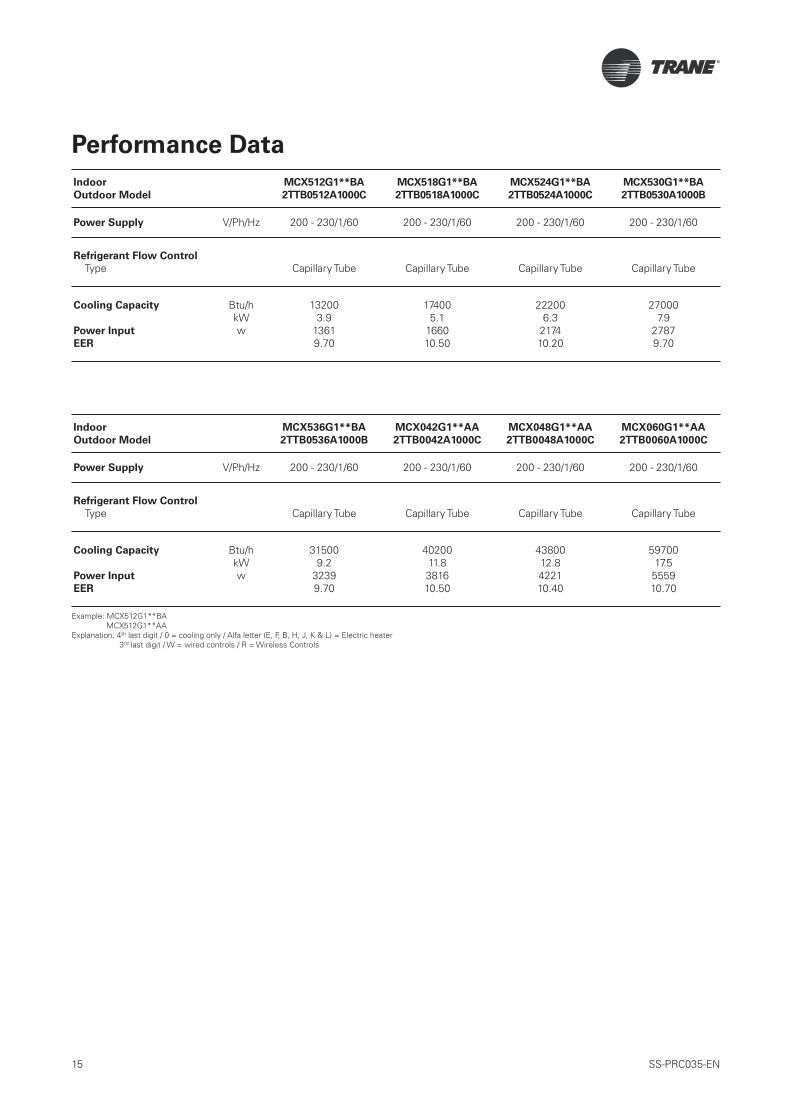
Performance Data
Indoor
Outdoor Model
MCX512G1**BA
2TTB0512A1000C
MCX518G1**BA
2TTB0518A1000C
MCX524G1**BA
2TTB0524A1000C
MCX530G1**BA
2TTB0530A1000B
Power Supply V/Ph/Hz 200 - 230/1/60 200 - 230/1/60 200 - 230/1/60 200 - 230/1/60
Refrigerant Flow Control
Type Capillary Tube Capillary Tube Capillary Tube Capillary Tube
Cooling Capacity
Power Input
EER
Btu/hkWw
132003.9
13619.70
174005.1
166010.50
222006.3
217410.20
270007.9
27879.70
Indoor
Outdoor Model
MCX536G1**BA
2TTB0536A1000B
MCX042G1**AA
2TTB0042A1000C
MCX048G1**AA
2TTB0048A1000C
MCX060G1**AA
2TTB0060A1000C
Power Supply V/Ph/Hz 200 - 230/1/60 200 - 230/1/60 200 - 230/1/60 200 - 230/1/60
Refrigerant Flow Control
Type Capillary Tube Capillary Tube Capillary Tube Capillary Tube
Cooling Capacity
Power Input
EER
Btu/hkWw
315009.2
32399.70
4020011.8381610.50
4380012.8422110.40
5970017.5
555910.70
Example: MCX512G1**BAMCX512G1**AA
Explanation: 4th last digit / 0 = cooling only / Alfa letter (E, F, B, H, J, K & L) = Electric heater 3rd last digit / W = wired controls / R = Wireless Controls

16 SS-PRC035-EN
Performance Table
Outdoor Unit: 2TTB0512A1000CIndoor Unit: MCX512G10WBA
Performance at 80/67/95
AIRFLOW (CFM): 400GROS. CAP(MBH): 13.2SENS. CAP(MBH): 7.5COMP. WATTS: 1152OD FAN WATTS: 175ID FAN WATTS: 34COMP. AMPS: 5.0OD FAN AMPS: 0.8ID FAN AMPS: 0.2NOM. SYS. AMPS: 5.9EER (BTU/WHR): 9.7
Performance Data Cooling-English Units
2TTB0512A1000C With MCX512G10WBA
AT 400 CFM
Gross Capacity in Btu/H x 1000
Outdoor Indoor Gross SENS.CAP.AT Entering D.B. TEMP. COMPR.
D.B. W.B. CAP. 72 74 76 78 80 kW
61 12.1 7.1 7.7 8.3 8.9 9.2 1.00
85 65 13.1 5.9 6.5 7.1 7.7 8.3 1.04
67 13.6 5.2 5.9 6.5 7.1 7.7 1.06
71 14.6 3.9 4.5 5.1 5.8 6.4 1.10
61 11.8 7.0 7.6 8.2 8.7 9.2 1.09
95 65 12.7 5.8 6.4 7.0 7.6 8.2 1.13
67 13.2 5.1 5.7 6.3 6.9 7.5 1.15
71 14.1 3.8 4.4 5.0 5.6 6.3 1.20
61 11.3 6.8 7.4 7.9 8.4 8.9 1.18
105 65 12.2 5.5 6.1 6.7 7.3 7.9 1.23
67 12.7 4.9 5.5 6.1 6.7 7.3 1.25
71 13.6 4.2 4.2 4.8 5.4 6.0 1.30
61 10.8 6.6 7.1 7.7 8.2 8.6 1.28
115 65 11.7 5.3 5.9 6.5 7.1 7.7 1.33
67 12.1 4.7 5.3 5.9 6.5 7.1 1.35
71 13.0 3.4 4.0 4.6 5.2 5.8 1.40
*Dry coil condition (Gross Capacity = Sensible Capacity)Gross Capacity and Comp. kW are valid only for Wet Coil
Performance at the Rating Conditions of 80/67 & 95℉
GROSS CAPACITY: 13.2 MBHAIRFLOW: 400 CFMSYSTEM POWER: 1361 WATTSNOM. SYSTEM AMPS: 5.9 AMPS
EER (BTU/W-HR): 9.7

17 SS-PRC035-EN
Performance Table
Performance Data Cooling-Metric Units
2TTB0512A1000C With MCX512G10WBA
AT 680 CMH
Gross Capacity in Kilowatts
Outdoor Indoor Gross SENS.CAP.AT Entering D.B. TEMP. COMPR.
D.B. W.B. CAP. 22.5 23.5 24.5 25.5 26.5 kW
16 3.5 2.1 2.3 2.4 2.6 2.7 1.00
30 18 3.8 1.7 1.9 2.1 2.3 2.4 1.04
19.5 4.0 1.5 1.7 1.9 2.1 2.2 1.06
22 4.3 1.1 1.3 1.5 1.7 1.9 1.10
16 3.4 2.1 2.2 2.4 2.6 2.7 1.09
35 18 3.7 1.7 1.9 2.0 2.2 2.4 1.13
19.5 3.9 1.5 1.7 1.9 2.0 2.2 1.15
22 4.1 1.1 1.3 1.5 1.6 1.8 1.20
16 3.3 2.0 2.2 2.3 2.5 2.6 1.18
40 18 3.6 1.6 1.8 2.0 2.1 2.3 1.23
19.5 3.7 1.4 1.6 1.8 2.0 2.1 1.25
22 4.0 1.2 1.2 1.4 1.6 1.8 1.30
16 3.2 1.9 2.1 2.3 2.4 2.5 1.28
45 18 3.4 1.6 1.7 1.9 2.1 2.3 1.33
19.5 3.5 1.4 1.6 1.7 1.9 2.1 1.35
22 3.8 1.0 1.2 1.3 1.5 1.7 1.40
*Dry coil condition (Gross Capacity = Sensible Capacity)Gross Capacity and Comp. kW are valid only for Wet Coil
Performance at the Rating Conditions of 26.5/19.5 & 35℃
GROSS CAPACITY: 3.9 kWAIRFLOW: 680 CMHSYSTEM POWER: 1361 WATTSNOM.SYSTEM AMPS: 5.9 AMPS

18 SS-PRC035-EN
Performance Table
Outdoor Unit: 2TTB0518A1000CIndoor Unit: MCX518G10WBA
Performance at 80/67/95
AIRFLOW (CFM): 475GROS. CAP(MBH): 17.4SENS. CAP(MBH): 11.2COMP. WATTS: 1440OD FAN WATTS: 175ID FAN WATTS: 45COMP. AMPS: 6.3OD FAN AMPS: 0.8ID FAN AMPS: 0.2NOM. SYS. AMPS: 7.2EER (BTU/WHR): 10.5
Performance Data Cooling-English Units
2TTB0518A1000C With MCX518G10WBA
AT 475 CFM
Gross Capacity in Btu/H x 1000
Outdoor Indoor Gross SENS.CAP.AT Entering D.B. TEMP. COMPR.
D.B. W.B. CAP. 72 74 76 78 80 kW
61 16.0 10.5 11.5 12.3 13.2 13.7 1.25
85 65 17.3 8.7 9.6 10.5 11.4 12.3 1.30
67 18.0 7.8 8.7 9.6 10.4 11.4 1.33
71 19.3 5.8 6.7 7.6 8.5 9.4 1.38
61 15.6 10.4 11.2 12.2 12.9 13.7 1.36
95 65 16.8 8.5 9.4 10.3 11.2 12.1 1.41
67 17.4 7.6 8.5 9.4 10.3 11.2 1.44
71 18.7 5.7 6.5 7.4 8.3 9.3 1.50
61 14.9 10.0 10.9 11.7 12.5 13.2 1.48
105 65 16.1 8.2 9.1 10.0 10.9 11.8 1.54
67 16.8 7.3 8.1 9.0 9.9 10.8 1.56
71 18.0 6.2 6.2 7.1 8.0 8.9 1.63
61 14.3 9.7 10.6 11.4 12.1 12.7 1.60
115 65 15.4 7.9 8.8 9.7 10.6 11.4 1.66
67 16.0 6.9 7.9 8.7 9.6 10.5 1.69
71 17.2 5.0 5.9 6.8 7.7 8.6 1.75
*Dry coil condition (Gross Capacity = Sensible Capacity)Gross Capacity and Comp. kW are valid only for Wet Coil
Performance at the Rating Conditions of 80/67 & 95℉
GROSS CAPACITY: 17.4 MBHAIRFLOW: 475 CFMSYSTEM POWER: 1660 WATTSNOM. SYSTEM AMPS: 7.2 AMPS
EER (BTU/W-HR): 10.5

19 SS-PRC035-EN
Performance Table
Performance Data Cooling-Metric Units
2TTB0518A1000C With MCX518G10WBA
AT 808 CMH
Gross Capacity in Kilowatts
Outdoor Indoor Gross SENS.CAP.AT Entering D.B. TEMP. COMPR.
D.B. W.B. CAP. 22.5 23.5 24.5 25.5 26.5 kW
16 4.7 3.1 3.4 3.6 3.9 4.0 1.25
30 18 5.1 2.6 2.8 3.1 3.3 3.6 1.30
19.5 5.3 2.3 2.5 2.8 3.1 3.3 1.33
22 5.7 1.7 2.0 2.2 2.5 2.8 1.38
16 4.6 3.0 3.3 3.6 3.8 4.0 1.36
35 18 4.9 2.5 2.8 3.0 3.3 3.6 1.41
19.5 5.1 2.2 2.5 2.7 3.0 3.3 1.44
22 5.5 1.7 1.9 2.2 2.4 2.7 1.50
16 4.4 2.9 3.2 3.4 3.6 3.9 1.48
40 18 4.7 2.4 2.7 2.9 3.2 3.4 1.54
19.5 4.9 2.1 2.4 2.6 2.9 3.2 1.56
22 5.3 1.8 1.8 2.1 2.3 2.6 1.63
16 4.2 2.8 3.1 3.3 3.5 3.7 1.60
45 18 4.5 2.3 2.6 2.8 3.1 3.4 1.66
19.5 4.7 2.0 2.3 2.6 2.8 3.1 1.69
22 5.0 1.5 1.7 2.0 2.3 2.5 1.75
*Dry coil condition (Gross Capacity = Sensible Capacity)Gross Capacity and Comp. kW are valid only for Wet Coil
Performance at the Rating Conditions of 26.5/19.5 & 35℃
GROSS CAPACITY: 5.1 kWAIRFLOW: 808 CMHSYSTEM POWER: 1660 WATTSNOM.SYSTEM AMPS: 7.2 AMPS

20 SS-PRC035-EN
Performance Table
Outdoor Unit: 2TTB0524A1000CIndoor Unit: MCX524G10WBA
Performance at 80/67/95
AIRFLOW (CFM): 600GROS. CAP(MBH): 22.2SENS. CAP(MBH): 14.3COMP. WATTS: 1932OD FAN WATTS: 179ID FAN WATTS: 63COMP. AMPS: 8.4OD FAN AMPS: 0.8ID FAN AMPS: 0.3NOM. SYS. AMPS: 9.5EER (BTU/WHR): 10.2
Performance Data Cooling-English Units
2TTB0524A1000C With MCX524G10WBA
AT 600 CFM
Gross Capacity in Btu/H x 1000
Outdoor Indoor Gross SENS.CAP.AT Entering D.B. TEMP. COMPR.
D.B. W.B. CAP. 72 74 76 78 80 kW
61 20.4 13.5 14.7 15.8 16.9 17.5 1.68
85 65 22.0 11.2 12.4 13.5 14.7 15.8 1.75
67 22.8 10.0 11.1 12.3 13.4 14.6 1.78
71 24.5 7.4 8.6 9.7 10.9 12.1 1.85
61 19.8 13.3 14.4 15.6 16.6 17.5 1.82
95 65 21.4 11.0 12.1 13.3 14.4 15.6 1.89
67 22.2 9.7 10.9 12.0 13.2 14.3 1.93
71 23.8 7.3 8.4 9.5 10.7 11.9 2.01
61 19.0 12.8 14.0 15.0 16.0 16.9 1.98
105 65 20.5 10.5 11.6 12.8 13.9 15.1 2.06
67 21.3 9.3 10.4 11.6 12.7 13.9 2.10
71 22.8 8.0 8.0 9.1 10.3 11.4 2.18
61 18.2 12.5 13.6 14.6 15.5 16.3 2.15
115 65 19.6 10.1 11.3 12.4 13.6 14.7 2.23
67 20.4 8.9 10.1 11.2 12.3 13.5 2.27
71 21.9 6.5 7.6 8.7 9.9 11.0 2.35
*Dry coil condition (Gross Capacity = Sensible Capacity)Gross Capacity and Comp. kW are valid only for Wet Coil
Performance at the Rating Conditions of 80/67 & 95℉
GROSS CAPACITY: 22.2 MBHAIRFLOW: 600 CFMSYSTEM POWER: 2174 WATTSNOM. SYSTEM AMPS: 9.5 AMPS
EER (BTU/W-HR): 10.2

21 SS-PRC035-EN
Performance Table
Performance Data Cooling-Metric Units
2TTB0524A1000C With MCX524G10WBA
AT 1020 CMH
Gross Capacity in Kilowatts
Outdoor Indoor Gross SENS.CAP.AT Entering D.B. TEMP. COMPR.
D.B. W.B. CAP. 22.5 23.5 24.5 25.5 26.5 kW
16 6.0 4.0 4.3 4.6 4.9 5.1 1.68
30 18 6.4 3.3 3.6 4.0 4.3 4.6 1.75
19.5 6.7 2.9 3.3 3.6 3.9 4.3 1.78
22 7.2 2.2 2.5 2.9 3.2 3.5 1.85
16 5.8 3.9 4.2 4.6 4.9 5.1 1.82
35 18 6.3 3.2 3.5 3.9 4.2 4.6 1.89
19.5 6.5 2.8 3.2 3.5 3.9 4.2 1.93
22 7.0 2.1 2.5 2.8 3.1 3.5 2.01
16 5.6 3.8 4.1 4.4 4.7 4.9 1.98
40 18 6.0 3.1 3.4 3.8 4.1 4.4 2.06
19.5 6.3 2.7 3.1 3.4 3.7 4.1 2.10
22 6.7 2.3 2.3 2.7 3.0 3.3 2.18
16 5.3 3.7 4.0 4.3 4.5 4.8 2.15
45 18 5.8 3.0 3.3 3.6 4.0 4.3 2.23
19.5 6.0 2.6 3.0 3.3 3.6 3.9 2.27
22 6.4 1.9 2.2 2.6 2.9 3.2 2.35
*Dry coil condition (Gross Capacity = Sensible Capacity)Gross Capacity and Comp. kW are valid only for Wet Coil
Performance at the Rating Conditions of 26.5/19.5 & 35℃
GROSS CAPACITY: 6.5 kWAIRFLOW: 1020 CMHSYSTEM POWER: 2174 WATTSNOM.SYSTEM AMPS: 9.5 AMPS

22 SS-PRC035-EN
Performance Table
Outdoor Unit: 2TTB0530A1000BIndoor Unit: MCX530G10WBA
Performance at 80/67/95
AIRFLOW (CFM): 750GROS. CAP(MBH): 27.0SENS. CAP(MBH): 18.2COMP. WATTS: 2496OD FAN WATTS: 211ID FAN WATTS: 80COMP. AMPS: 10.9OD FAN AMPS: 0.9ID FAN AMPS: 0.4NOM. SYS. AMPS: 12.1EER (BTU/WHR): 9.7
Performance Data Cooling-English Units
2TTB0530A1000B With MCX530G10WBA
AT 750 CFM
Gross Capacity in Btu/H x 1000
Outdoor Indoor Gross SENS.CAP.AT Entering D.B. TEMP. COMPR.
D.B. W.B. CAP. 72 74 76 78 80 kW
61 24.8 17.2 18.7 20.1 21.5 22.3 2.17
85 65 26.8 14.2 15.7 17.2 18.6 20.1 2.26
67 27.8 12.7 14.1 15.6 17.0 18.5 2.30
71 29.9 9.5 11.0 12.4 13.9 15.3 2.39
61 24.1 16.9 18.3 19.8 21.1 22.3 2.35
95 65 26.0 13.9 15.4 16.9 18.3 19.8 2.45
67 27.0 12.3 13.8 15.3 16.8 18.2 2.50
71 29.0 9.2 10.6 12.1 13.6 15.1 2.59
61 23.1 16.3 17.8 19.1 20.3 21.5 2.56
105 65 25.0 13.4 14.8 16.3 17.7 19.2 2.66
67 26.0 11.8 13.2 14.7 16.2 17.6 2.71
71 27.8 10.1 10.2 11.6 13.1 14.5 2.82
61 22.2 15.8 17.3 18.5 19.8 20.8 2.77
115 65 23.9 12.9 14.4 15.8 17.2 18.7 2.88
67 24.8 11.3 12.8 14.2 15.7 17.1 2.93
71 26.7 8.2 9.7 11.1 12.6 14.0 3.04
*Dry coil condition (Gross Capacity = Sensible Capacity)Gross Capacity and Comp. kW are valid only for Wet Coil
Performance at the Rating Conditions of 80/67 & 95℉
GROSS CAPACITY: 27.0 MBHAIRFLOW: 750 CFMSYSTEM POWER: 2787 WATTSNOM. SYSTEM AMPS: 12.1 AMPS
EER (BTU/W-HR): 9.7

23 SS-PRC035-EN
Performance Table
Performance Data Cooling - Metric Units
2TTB0530A1000B With MCX530G10WBA
AT 1275 CMH
Gross Capacity in Kilowatts
Outdoor Indoor Gross SENS.CAP.AT Entering D.B. TEMP. COMPR.
D.B. W.B. CAP. 22.5 23.5 24.5 25.5 26.5 kW
16 7.3 5.0 5.5 5.9 6.3 6.5 2.17
30 18 7.9 4.2 4.6 5.0 5.5 5.9 2.26
19.5 8.2 3.7 4.1 4.6 5.0 5.4 2.30
22 8.8 2.8 3.2 3.6 4.1 4.5 2.39
16 7.1 5.0 5.4 5.8 6.2 6.5 2.35
35 18 7.6 4.1 4.5 4.9 5.4 5.8 2.45
19.5 7.9 3.6 4.1 4.5 4.9 5.3 2.50
22 8.5 2.7 3.1 3.6 4.0 4.4 2.59
16 6.8 4.8 5.2 5.6 6.0 6.3 2.56
40 18 7.3 3.9 4.3 4.8 5.2 5.6 2.66
19.5 7.6 3.5 3.9 4.3 4.7 5.2 2.71
22 8.2 3.0 3.0 3.4 3.8 4.2 2.82
16 6.5 4.6 5.1 5.4 5.8 6.1 2.77
45 18 7.0 3.8 4.2 4.6 5.1 5.5 2.88
19.5 7.3 3.3 3.8 4.2 4.6 5.0 2.93
22 7.8 2.4 2.8 3.3 3.7 4.1 3.04
*Dry coil condition (Gross Capacity = Sensible Capacity)Gross Capacity and Comp. kW are valid only for Wet Coil
Performance at the Rating Conditions of 26.5/19.5 & 35℃
GROSS CAPACITY: 7.9 kWAIRFLOW: 1275 CMHSYSTEM POWER: 2787 WATTSNOM.SYSTEM AMPS: 12.1 AMPS
24 SS-PRC035-EN
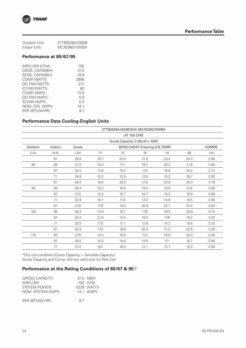
Performance Table
Outdoor Unit: 2TTB0536A1000BIndoor Unit: MCX536G10WBA
Performance at 80/67/95
AIRFLOW (CFM): 750GROS. CAP(MBH): 31.5SENS. CAP(MBH): 19.9COMP. WATTS: 2948OD FAN WATTS: 211ID FAN WATTS: 80COMP. AMPS: 12.8OD FAN AMPS: 0.9ID FAN AMPS: 0.4NOM. SYS. AMPS: 14.1EER (BTU/WHR): 9.7
Performance Data Cooling-English Units
2TTB0536A1000B With MCX536G10WBA
AT 750 CFM
Gross Capacity in Btu/H x 1000
Outdoor Indoor Gross SENS.CAP.AT Entering D.B. TEMP. COMPR.
D.B. W.B. CAP. 72 74 76 78 80 kW
61 29.0 18.7 20.4 21.9 23.4 24.3 2.56
85 65 31.3 15.5 17.1 18.7 20.3 21.9 2.66
67 32.5 13.8 15.4 17.0 18.6 20.2 2.72
71 34.9 10.3 12.0 13.5 15.2 16.7 2.83
61 28.2 18.5 20.0 21.6 23.0 24.3 2.78
95 65 30.4 15.2 16.8 18.4 19.9 21.6 2.89
67 31.5 13.5 15.1 16.7 18.3 19.9 2.95
71 33.9 10.1 11.6 13.2 14.8 16.5 3.06
61 27.0 17.8 19.4 20.9 22.1 23.4 3.03
105 65 29.2 14.6 16.1 17.8 19.3 20.9 3.14
67 30.4 12.9 14.4 16.0 17.6 19.2 3.20
71 32.5 11.0 11.1 12.6 14.2 15.8 3.33
61 25.9 17.3 18.8 20.2 21.5 22.6 3.28
115 65 27.9 14.0 15.6 17.2 18.8 20.3 3.40
67 29.0 12.3 14.0 15.5 17.1 18.7 3.46
71 31.2 9.0 10.5 12.1 13.7 15.3 3.58
*Dry coil condition (Gross Capacity = Sensible Capacity)Gross Capacity and Comp. kW are valid only for Wet Coil
Performance at the Rating Conditions of 80/67 & 95℉
GROSS CAPACITY: 31.5 MBHAIRFLOW: 750 CFMSYSTEM POWER: 3239 WATTSNOM. SYSTEM AMPS: 14.1 AMPS
EER (BTU/W-HR): 9.7

25 SS-PRC035-EN
Performance Table
Performance Data Cooling - Metric Units
2TTB0536A1000B With MCX536G10WBA
AT 1275 CMH
Gross Capacity in Kilowatts
Outdoor Indoor Gross SENS.CAP.AT Entering D.B. TEMP. COMPR.
D.B. W.B. CAP. 22.5 23.5 24.5 25.5 26.5 kW
16 8.5 5.5 6.0 6.4 6.9 7.1 2.56
30 18 9.2 4.5 5.0 5.5 6.0 6.4 2.66
19.5 9.5 4.0 4.5 5.0 5.4 5.9 2.72
22 10.2 3.0 3.5 4.0 4.4 4.9 2.83
16 8.3 5.4 5.9 6.3 6.7 7.1 2.78
35 18 8.9 4.5 4.9 5.4 5.8 6.3 2.89
19.5 9.2 3.9 4.4 4.9 5.4 5.8 2.95
22 9.9 2.9 3.4 3.9 4.3 4.8 3.06
16 7.9 5.2 5.7 6.1 6.5 6.9 3.03
40 18 8.6 4.3 4.7 5.2 5.7 6.1 3.14
19.5 8.9 3.8 4.2 4.7 5.2 5.6 3.20
22 9.5 3.2 3.2 3.7 4.2 4.6 3.33
16 7.6 5.1 5.5 5.9 6.3 6.6 3.28
45 18 8.2 4.1 4.6 5.0 5.5 6.0 3.40
19.5 8.5 3.6 4.1 4.5 5.0 5.5 3.46
22 9.1 2.6 3.1 3.5 4.0 4.5 3.58
*Dry coil condition (Gross Capacity = Sensible Capacity)Gross Capacity and Comp. kW are valid only for Wet Coil
Performance at the Rating Conditions of 26.5/19.5 & 35℃
GROSS CAPACITY: 9.2 kWAIRFLOW: 123239 WATTSNOM.SYSTEM AMPS: 14.1 AMPS

26 SS-PRC035-EN
Performance Table
Outdoor Unit: 2TTB0042A1000AIndoor Unit: MCX042G10WAA
Performance at 80/67/95
AIRFLOW (CFM): 1200GROS. CAP(MBH): 40.2SENS. CAP(MBH): 27.6COMP. WATTS: 3447OD FAN WATTS: 249ID FAN WATTS: 120COMP. AMPS: 15.0OD FAN AMPS: 1.1ID FAN AMPS: 0.5NOM. SYS. AMPS: 16.6EER (BTU/WHR): 10.5
Performance Data Cooling-English Units
2TTB0042A1000B With MCX042G10WAA
AT 1200 CFM
Gross Capacity in Btu/H x 1000
Outdoor Indoor Gross SENS.CAP.AT Entering D.B. TEMP. COMPR.
D.B. W.B. CAP. 72 74 76 78 80 kW
61 37.0 26.1 27.4 30.5 32.6 33.9 2.99
85 65 39.9 21.6 23.8 26.0 28.3 30.5 3.12
67 41.5 19.2 21.5 23.7 25.9 28.1 3.17
71 44.5 14.4 16.6 18.8 21.1 23.3 3.31
61 36.0 25.7 27.9 30.1 32.0 33.8 3.25
95 65 38.8 21.2 23.3 25.6 27.8 30.0 3.38
67 40.2 18.7 21.0 23.2 25.4 27.6 3.45
71 43.2 14.0 16.2 18.4 20.6 22.9 3.58
61 34.5 24.7 27.0 29.0 30.8 32.6 3.54
105 65 37.3 20.3 22.5 24.7 26.9 29.1 3.67
67 38.7 18.0 20.1 22.3 24.5 26.8 3.74
71 41.5 15.4 15.4 17.6 19.8 22.0 3.89
61 33.0 24.1 26.2 28.2 30.0 31.5 3.83
115 65 35.6 19.5 21.8 23.9 26.2 28.3 3.98
67 37.0 17.2 19.5 21.6 23.8 26.0 4.05
71 39.8 12.5 14.6 16.8 19.1 21.3 4.19
*Dry coil condition (Gross Capacity = Sensible Capacity)Gross Capacity and Comp. kW are valid only for Wet Coil
Performance at the Rating Conditions of 80/67 & 95℉
GROSS CAPACITY: 40.2 MBHAIRFLOW: 1200 CFMSYSTEM POWER: 3816 WATTSNOM. SYSTEM AMPS: 16.1 AMPS
EER (BTU/W-HR): 10.5

27 SS-PRC035-EN
Performance Table
Performance Data Cooling - Metric Units
2TTB0042A1000C With MCX536G10WAA
AT 2040 CMH
Gross Capacity in Kilowatts
Outdoor Indoor Gross SENS.CAP.AT Entering D.B. TEMP. COMPR.
D.B. W.B. CAP. 22.5 23.5 24.5 25.5 26.5 kW
16 10.8 7.6 8.3 8.9 9.6 9.9 2.99
30 18 11.7 6.3 7.0 7.6 8.3 8.9 3.12
19.5 12.1 5.6 6.3 6.9 7.6 8.2 3.17
22 13.0 4.2 4.9 5.5 6.2 6.8 3.31
16 10.5 7.5 8.2 8.8 9.4 9.9 3.25
35 18 11.4 6.2 6.8 7.5 8.1 8.8 3.38
19.5 11.8 5.5 6.2 6.8 7.5 8.1 3.45
22 12.7 4.1 4.7 5.4 6.0 6.7 3.58
16 10.1 7.2 7.9 8.5 9.0 9.6 3.54
40 18 10.9 5.9 6.6 7.2 7.9 8.5 3.67
19.5 11.3 5.3 5.9 6.5 7.2 7.8 3.74
22 12.2 4.5 4.5 5.2 5.8 6.4 3.89
16 9.7 7.0 7.7 8.2 8.8 9.2 3.83
45 18 10.4 5.7 6.4 7.0 7.7 8.3 3.98
19.5 10.8 5.0 5.7 6.3 7.0 7.6 4.05
22 11.7 3.7 4.3 4.9 5.6 6.2 4.19
*Dry coil condition (Gross Capacity = Sensible Capacity)Gross Capacity and Comp. kW are valid only for Wet Coil
Performance at the Rating Conditions of 26.5/19.5 & 35℃
GROSS CAPACITY: 11.8 kWAIRFLOW: 2040 CMHSYSTEM POWER: 3816 WATTSNOM.SYSTEM AMPS: 16.6 AMPS

28 SS-PRC035-EN
Performance Table
Outdoor Unit: 2TTB0048A1000CIndoor Unit: MCX048G10WAA
Performance at 80/67/95
AIRFLOW (CFM): 1200GROS. CAP(MBH): 43.8SENS. CAP(MBH): 28.9COMP. WATTS: 3874OD FAN WATTS: 233ID FAN WATTS: 114COMP. AMPS: 16.8OD FAN AMPS: 1.0ID FAN AMPS: 0.5NOM. SYS. AMPS: 18.4EER (BTU/WHR): 10.4
Performance Data Cooling-English Units
2TTB0042A1000B With MCX042G10WAA
AT 1200 CFM
Gross Capacity in Btu/H x 1000
Outdoor Indoor Gross SENS.CAP.AT Entering D.B. TEMP. COMPR.
D.B. W.B. CAP. 72 74 76 78 80 kW
61 40.3 27.2 29.6 31.8 34.0 35.3 3.36
85 65 43.5 22.5 24.9 27.2 29.5 31.8 3.50
67 45.2 20.1 22.4 24.7 27.0 29.4 3.57
71 48.5 15.0 17.4 19.6 22.0 24.3 3.72
61 39.2 26.9 29.1 31.4 33.4 35.3 3.65
95 65 42.2 22.1 24.4 26.7 29.0 31.3 3.80
67 43.8 19.6 21.9 24.2 26.6 28.9 3.87
71 47.1 14.6 16.9 19.2 21.5 23.9 4.03
61 37.5 25.8 28.1 30.3 32.2 34.0 3.98
105 65 40.6 21.2 23.5 25.8 28.1 30.4 4.13
67 42.2 18.7 21.0 23.3 25.6 27.9 4.21
71 45.2 16.0 16.1 18.4 20.7 23.0 4.37
61 35.9 25.1 27.3 29.4 31.3 32.9 4.30
115 65 38.8 20.4 22.7 25.0 27.3 29.6 4.47
67 40.3 17.9 20.3 22.5 24.9 27.1 4.55
71 43.3 13.1 15.3 17.6 19.9 22.2 4.71
*Dry coil condition (Gross Capacity = Sensible Capacity)Gross Capacity and Comp. kW are valid only for Wet Coil
Performance at the Rating Conditions of 80/67 & 95℉
GROSS CAPACITY: 43.8 MBHAIRFLOW: 1200 CFMSYSTEM POWER: 4221 WATTSNOM. SYSTEM AMPS: 18.4 AMPS
EER (BTU/W-HR): 10.4

29 SS-PRC035-EN
Performance Table
Performance Data Cooling - Metric Units
2TTB0048A1000C With MCX048G10WAA
AT 2040 CMH
Gross Capacity in Kilowatts
Outdoor Indoor Gross SENS.CAP.AT Entering D.B. TEMP. COMPR.
D.B. W.B. CAP. 22.5 23.5 24.5 25.5 26.5 kW
16 11.8 8.0 8.7 9.3 10.0 10.4 3.36
30 18 12.7 6.6 7.3 8.0 8.7 9.3 3.50
19.5 13.2 5.9 6.6 7.3 7.9 8.6 3.57
22 14.2 4.4 5.1 5.7 6.5 7.1 3.72
16 11.5 7.9 8.5 9.2 9.8 10.4 3.65
35 18 12.4 6.5 7.1 7.8 8.5 9.2 3.80
19.5 12.8 5.7 6.4 7.1 7.8 8.5 3.87
22 13.8 4.3 4.9 5.6 6.3 7.0 4.03
16 11.0 7.6 8.2 8.9 9.4 10.0 3.98
40 18 11.9 6.2 6.9 7.6 8.2 8.9 4.13
19.5 12.4 5.5 6.1 6.8 7.5 8.2 5.21
22 13.2 4.7 4.7 5.4 6.1 6.7 4.37
16 10.5 7.4 8.0 8.6 9.2 9.6 4.30
45 18 11.4 6.0 6.7 7.3 8.0 8.7 4.47
19.5 11.8 5.3 6.0 6.6 7.3 7.9 4.55
22 12.7 3.8 4.5 5.2 5.8 6.5 4.71
*Dry coil condition (Gross Capacity = Sensible Capacity)Gross Capacity and Comp. kW are valid only for Wet Coil
Performance at the Rating Conditions of 26.5/19.5 & 35℃
GROSS CAPACITY: 12.8 kWAIRFLOW: 2040 CMHSYSTEM POWER: 4221 WATTSNOM.SYSTEM AMPS: 18.4 AMPS

30 SS-PRC035-EN
Performance Table
Outdoor Unit: 2TTB0060A1000CIndoor Unit: MCX048G10WAA
Performance at 80/67/95
AIRFLOW (CFM): 1350GROS. CAP(MBH): 59.7SENS. CAP(MBH): 38.8COMP. WATTS: 5150OD FAN WATTS: 295ID FAN WATTS: 114COMP. AMPS: 22.4OD FAN AMPS: 1.3ID FAN AMPS: 0.5NOM. SYS. AMPS: 24.2EER (BTU/WHR): 10.7
Performance Data Cooling-English Units
2TTB0060A1000C With MCX060G10WAA
AT 1350 CFM
Gross Capacity in Btu/H x 1000
Outdoor Indoor Gross SENS.CAP.AT Entering D.B. TEMP. COMPR.
D.B. W.B. CAP. 72 74 76 78 80 kW
61 54.9 36.6 39.9 42.8 45.8 47.6 4.47
85 65 59.3 30.3 33.5 36.6 39.7 42.8 4.66
67 61.5 27.0 30.1 33.3 36.3 39.5 4.74
71 66.1 20.2 23.4 26.4 29.7 32.7 4.94
61 53.4 36.1 39.1 42.3 44.9 47.5 4.85
95 65 57.5 29.7 32.8 36.0 39.0 42.2 5.05
67 59.7 26.3 29.5 32.6 35.7 38.8 5.15
71 64.2 19.7 22.7 25.9 28.9 32.2 5.35
61 51.2 34.8 37.9 40.8 43.3 45.8 5.29
105 65 55.3 28.5 31.6 34.7 37.8 40.9 5.49
67 57.5 25.2 28.2 31.4 34.4 37.6 5.59
71 61.6 21.6 21.7 24.7 27.9 30.9 5.81
61 49.0 33.8 36.8 39.5 42.1 44.3 5.72
115 65 52.9 27.5 30.6 33.6 36.8 39.8 5.94
67 54.9 24.1 27.4 30.3 33.5 36.5 6.05
71 59.0 17.6 20.6 23.7 26.8 29.9 6.26
*Dry coil condition (Gross Capacity = Sensible Capacity)Gross Capacity and Comp. kW are valid only for Wet Coil
Performance at the Rating Conditions of 80/67 & 95℉
GROSS CAPACITY: 59.7 MBHAIRFLOW: 1350 CFMSYSTEM POWER: 5559 WATTSNOM. SYSTEM AMPS: 24.2 AMPS
EER (BTU/W-HR): 10.7

31 SS-PRC035-EN
Performance Table
Performance Data Cooling - Metric Units
2TTB060A1000C With MCX048G10WAA
AT 2295 CMH
Gross Capacity in Kilowatts
Outdoor Indoor Gross SENS.CAP.AT Entering D.B. TEMP. COMPR.
D.B. W.B. CAP. 22.5 23.5 24.5 25.5 26.5 kW
16 16.1 10.7 11.7 12.6 13.4 13.9 4.47
30 18 17.4 8.9 9.8 10.7 11.6 12.5 4.66
19.5 18.0 7.9 8.8 9.8 10.6 11.6 4.74
22 19.4 5.9 6.9 7.7 8.7 9.6 4.94
16 15.6 10.6 11.5 12.4 13.2 13.9 4.85
35 18 16.9 8.7 9.6 10.5 11.4 12.4 5.05
19.5 17.5 7.7 8.6 9.6 10.5 11.4 5.15
22 18.8 5.8 6.7 7.6 8.5 9.4 5.35
16 15.0 10.2 11.1 12.0 12.7 13.4 5.29
40 18 16.2 8.4 9.3 10.2 11.1 12.0 5.49
19.5 16.8 7.4 8.3 9.2 10.1 11.0 5.59
22 18.0 6.3 6.3 7.2 8.2 9.1 5.81
16 14.4 9.9 10.8 11.6 12.3 13.0 5.72
45 18 15.5 8.0 9.0 9.9 10.8 11.7 5.94
19.5 16.1 7.1 8.0 8.9 9.8 10.7 6.05
22 17.3 5.1 6.0 6.9 7.8 8.8 6.26
*Dry coil condition (Gross Capacity = Sensible Capacity)Gross Capacity and Comp. kW are valid only for Wet Coil
Performance at the Rating Conditions of 26.5/19.5 & 35℃
GROSS CAPACITY: 17.5 kWAIRFLOW: 2295 CMHSYSTEM POWER: 5559 WATTSNOM.SYSTEM AMPS: 24.2 AMPS

32 SS-PRC035-EN
MCX512G10WBA
2TTB0512A1000C
Wiring Diagram

33 SS-PRC035-EN
Wiring Diagram
MCX518G10WBA
2TTB0518A1000C

34 SS-PRC035-EN
Wiring Diagram
MCX524G10WBA
2TTB0524A1000C

35 SS-PRC035-EN
MCX530G10WBA
2TTB0530A1000B
Wiring Diagram

36 SS-PRC035-EN
MCX536G10WBA
2TTB0536A1000B
Wiring Diagram

37 SS-PRC035-EN
MCX042G10WAA
2TTB0042A1000C
Wiring Diagram
Field install transformerSpecs:220 / 24 Volt 50/60HzVA:25 VAPart # 325-2623

38 SS-PRC035-EN
MCX048G10WAA
2TTB0048A1000C
Wiring Diagram
Field install transformerSpecs:220 / 24 Volt 50/60HzVA:25 VAPart # 325-2623

39 SS-PRC035-EN
MCX060G10WAA
2TTB0060A1000C
Wiring Diagram
Field install transformerSpecs:220 / 24 Volt 50/60HzVA:25 VAPart # 325-2623

40 SS-PRC035-EN
2TTB0 Outline DrawingNote:All dimensions are in inches (mm)
Dimensions
Model A B C D E
2TTB0512A 25.5 (648) 18.8 (476) 19.8 (502) 5/8 (16) 1/4 (6)
2TTB0518A 25.5 (648) 18.8 (476) 19.8 (502) 5/8 (16) 1/4 (6)
2TTB0524A 25.5 (648) 18.8 (476) 19.8 (502) 3/4 (19) 5/16 (8)
2TTB0530B 25.6 (651) 25.6 (651) 28.5 (724) 3/4 (19) 5/16 (8)
2TTB0536B 25.6 (651) 25.6 (651) 28.5 (724) 3/4 (19) 5/16 (8)
2TTB0042A 28.8 (730) 28.5 (724) 25.6 (651) 7/8 (22) 3/8 (10)
2TTB0048A 28.8 (730) 28.5 (724) 25.6 (651) 1-1/8 (29) 3/8 (10)
2TTB0060A 32.8 (832) 829 (32.6) 29.8 (756) 1-1/8 (29) 3/8 (10)

41 SS-PRC035-EN
Dimensions
MCX512-536G1 Outline DrawingNote:All dimensions are in inches (mm)
ModelCONN.Sizes Connection
TypeA B C
Liquid Suction in. (mm) in. (mm) Each
MCX512G1 1/4 (6.4) 1/2 (12.7) FLARED 42.28 (1074) 34.61 (879) 4
MCX518G1 1/4 (6.4) 1/2 (12.7) FLARED 42.28 (1074) 34.61 (879) 4
MCX524G1 3/8 (9.5) 5/8 (15.9) FLARED 51.13 (1324) 44.45 (1129) 4
MCX530G1 3/8 (9.5) 5/8 (15.9) FLARED 61.97 (1574) 54.29 (1379) 6
MCX536G1 3/8 (9.5) 3/4 (19.0) FLARED 61.97 (1574) 54.29 (1379) 6

42 SS-PRC035-EN
Dimensions
MCX042-060G1 Outline DrawingNote:All dimensions are in inches (mm)
ModelCONN.Sizes Connection
TypeA B C D
Liquid Suction in. (mm) in. (mm) Each in. (mm)
MCX042G1 3/8 (9.5) 7/8 (22) BRAZED 71.81 (1824) 64.13 (1629) 8 15.76 (400)
MCX048G1 3/8 (9.5) 1-1/8 (28.6) BRAZED 71.81 (1824) 64.13 (1629) 8 15.76 (400)
MCX060G1 3/8 (9.5) 1-1/8 (28.6) BRAZED 81.65 (2047) 73.98 (1879) 8 23.64 (600)

© 2011 Trane All rights reserved
SS-PRC035-EN October 2011
Trane optimizes the performance of homes and buildings around the world. A business of Ingersoll Rand, the leader in creating and sustaining safe, comfortable and energy effi cient environments, Trane offers a broad portfolio of advanced controls and HVAC systems, comprehensive building services, and parts. For more information, visit www.Trane.com.
Trane has a policy of continuous product and product data improvement and reserves the right to change design and specifi cations without notice.