process industry practices piping - …docshare01.docshare.tips/files/4473/44733423.pdf · process...
TRANSCRIPT
COMPLETE REVISION October 2007
Process Industry Practices Piping
PIP PNFJ8000 Jacketed Piping
Fabrication and Installation Details
PURPOSE AND USE OF PROCESS INDUSTRY PRACTICES In an effort to minimize the cost of process industry facilities, this Practice has been prepared from the technical requirements in the existing standards of major industrial users, contractors, or standards organizations. By harmonizing these technical requirements into a single set of Practices, administrative, application, and engineering costs to both the purchaser and the manufacturer should be reduced. While this Practice is expected to incorporate the majority of requirements of most users, individual applications may involve requirements that will be appended to and take precedence over this Practice. Determinations concerning fitness for purpose and particular matters or application of the Practice to particular project or engineering situations should not be made solely on information contained in these materials. The use of trade names from time to time should not be viewed as an expression of preference but rather recognized as normal usage in the trade. Other brands having the same specifications are equally correct and may be substituted for those named. All Practices or guidelines are intended to be consistent with applicable laws and regulations including OSHA requirements. To the extent these Practices or guidelines should conflict with OSHA or other applicable laws or regulations, such laws or regulations must be followed. Consult an appropriate professional before applying or acting on any material contained in or suggested by the Practice.
This Practice is subject to revision at any time.
© Process Industry Practices (PIP), Construction Industry Institute, The University of Texas at Austin, 3925 West Braker Lane (R4500), Austin, Texas 78759. PIP member companies and subscribers may copy this Practice for their internal use. Changes, overlays, addenda, or modifications of any kind are not permitted within any PIP Practice without the express written authorization of PIP.
PRINTING HISTORY July 2001 Issued October 2007 Complete Revision
Not printed with State funds
COMPLETE REVISION October 2007
Process Industry Practices Piping
PIP PNFJ8000 Jacketed Piping
Fabrication and Installation Details
Table of Contents
1. Introduction.................................2 1.1 Purpose............................................ 2 1.2 Scope............................................... 2
2. References ..................................2 2.1 Process Industry Practices .............. 2 2.2 Industry Codes and Standards ........ 2
3. Requirements..............................2 3.1 General ............................................ 2 3.2 Materials of Construction ................. 3 3.3 Design.............................................. 3 3.4 Testing, Inspection, Examination,
and Repair ....................................... 4 3.5 Valve Identification........................... 5
4. Index of Drawings.......................6
Process Industry Practices Page 1 of 7
PIP PNFJ8000 COMPLETE REVISION Jacketed Piping Fabrication and Installation Details October 2007
1. Introduction
1.1 Purpose This Practice provides requirements for the design, fabrication, and installation of jacketed piping systems.
1.2 Scope This Practice describes the requirements for the design, material selection, fabrication, installation, inspection, and testing of jacketed piping systems.
2. References
Applicable parts of the following Practices and industry codes and standards shall be considered an integral part of this Practice. The latest edition in effect at the date of contract award shall be used, except as otherwise noted. Short titles will be used herein where appropriate.
2.1 Process Industry Practices (PIP) – PIP PNC00004 - Piping Flexibility Analysis Criteria for ASME B31.3 Metallic
Piping – PIP PNE00012 - Piping Examination and Leak Test Guide – PIP PNSC0001 - ASME B31.3 Metallic Piping Fabrication and Examination
Specification – PIP PNSM0110 – Procurement of Valves
2.2 Industry Codes and Standards
• American Society of Mechanical Engineers (ASME) – ASME B16.5 - Pipe Flanges and Flanged Fittings – ASME B31.3 - Process Piping
3. Requirements
3.1 General 3.1.1 The fabrication details in this Practice shall be used in the design and
fabrication of jacketed piping.
3.1.2 Any substitution to or variance from this Practice shall be approved by purchaser before implementation.
3.1.3 Codes, standards, and specifications referenced in this Practice, the piping line class specifications, valve purchase descriptions, or any referenced document form a part of the requirements of this Practice in the manner and to the extent specified.
Page 2 of 7 Process Industry Practices
COMPLETE REVISION PIP PNFJ8000 October 2007 Jacketed Piping Fabrication and Installation Details
3.2 Materials of Construction 3.2.1 Materials shall be in accordance with the PIP Piping Material Specifications
or the PIP Valve Descriptions.
3.2.2 All materials shall be new and unused.
3.2.3 Substitution of materials specified in the design or specified in the PIP Valve Descriptions shall not be permitted without written authorization from the purchaser.
3.3 Design 3.3.1 Codes and Standards
3.3.1.1 Jacketed piping design shall be in accordance with the latest revision of the standards noted in the PIP Piping Material Specification or in the PIP Valve Description.
3.3.1.2 Except as otherwise specified in this Practice, jacketed piping shall be in accordance with PIP PNE00012.
3.3.1.3 Except as otherwise specified in this Practice, jacketed piping shall be in accordance with PIP PNSC0001.
3.3.1.4 Except as otherwise specified in this Practice, jacketed piping, including integrally cast jacketed valves, base valves, and all types of fabricated jackets, shall be in accordance with PIP PNSM0110.
3.3.2 Pressure-Temperature Ratings Comment: Certain types of flanges common in jacketed piping may not be
entirely in accordance with ASME B16.5 pressure-temperature ratings.
If requested, information on the pressure-temperature ratings shall be submitted to the purchaser for approval.
3.3.3 Piping Design 3.3.3.1 The supplier’s designer shall ensure that the jacketed piping details
shown in this Practice are used in the intended manner.
Comment: Some designs shown in this Practice are not acceptable for all temperature ranges or for large differences in core and jacket pipe. Cautionary notes are provided on details if the large thermal strains on the assembly may cause failure.
3.3.3.2 The appropriate flexibility analysis shall be performed in accordance with PIP PNC00004.
3.3.3.3 Additional thermal and mechanical analysis methods may be required to fully qualify the design.
3.3.3.4 The supplier’s designer shall ensure that each detail is used with the appropriate heat transfer fluid in accordance with the referenced PIP Piping Material Specification.
Process Industry Practices Page 3 of 7
PIP PNFJ8000 COMPLETE REVISION Jacketed Piping Fabrication and Installation Details October 2007
Comment: Each design within a detail group (e.g., jacket termination) may not provide the same amount of heat transfer to the core pipe.
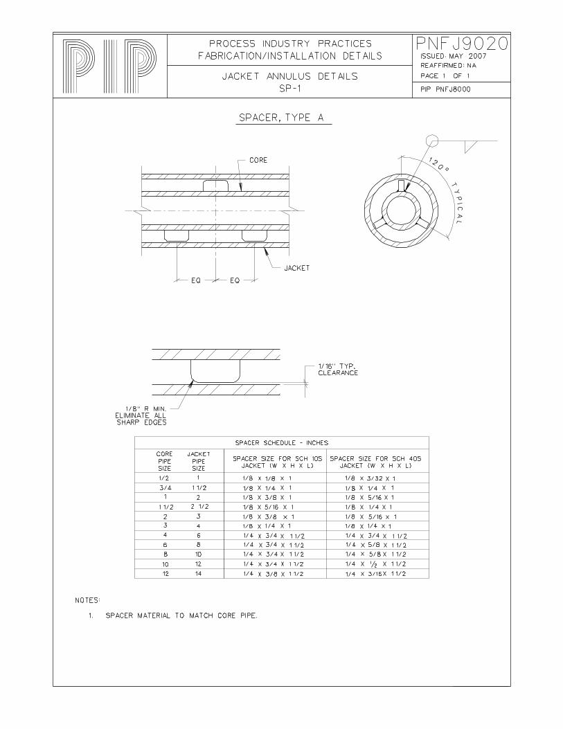
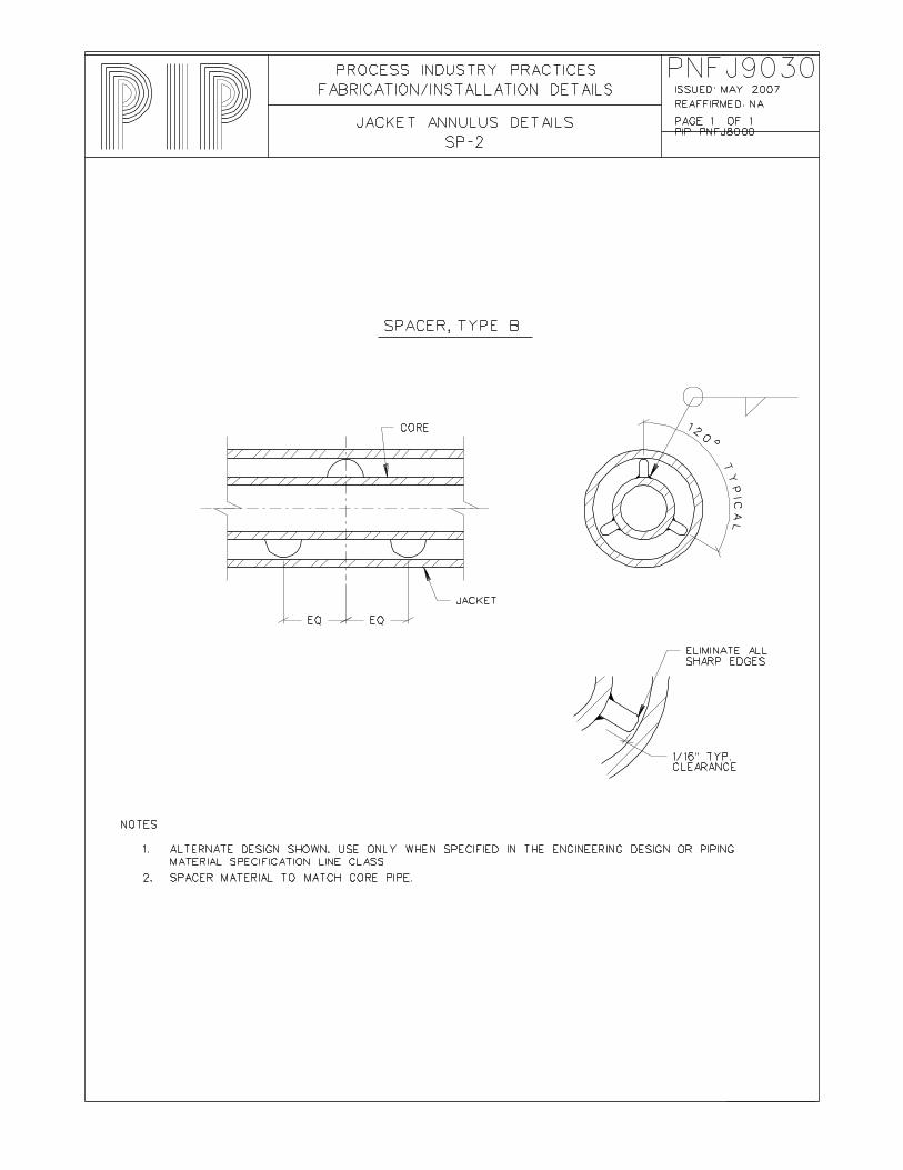
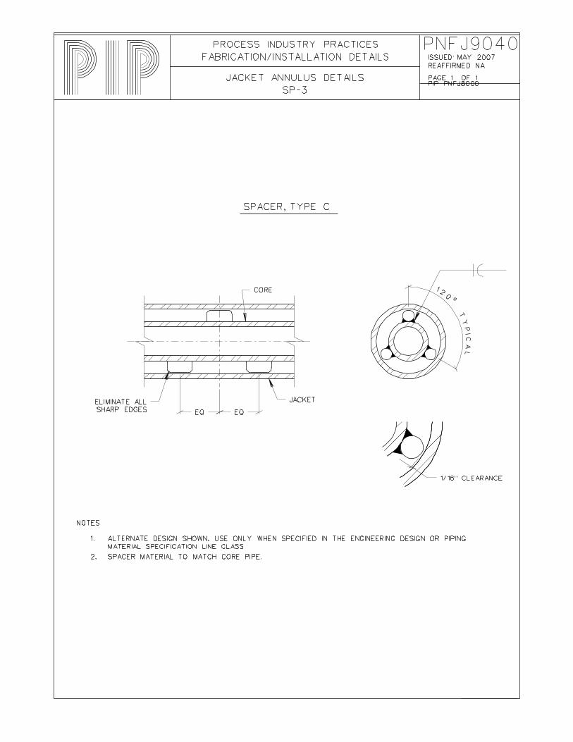
3.3.4 Use of Spacers 3.3.4.1 Uniformity of the jacket annulus shall be maintained. Spacers shall
be used in accordance with the following requirements:
a. Maximum distance between spacer groups or spacers and jacket end termination shall be 2.1 meters (7 feet) for core NPS 2 and smaller.
b. Maximum distance between spacer groups or spacers and jacket end termination shall be 3.1 meters (10 feet) for core NPS 3 and greater.
c. Spacers or jacket end termination shall be placed within 1.2 meters (4 feet) of the tangent point of elbows or center point of concentric fittings.
d. At least one spacer group or jacket end termination shall be provided for each straight run of pipe.
3.3.4.2 Spacers shall be considered in the flexibility analysis.
3.3.5 Layout Considerations 3.3.5.1 Jacketed piping systems shall be designed to be efficient in
transferring heat from the heating medium to the core. This is dependent upon how well fluid flows through the jacket.
3.3.5.2 For liquid-heated jacketed piping, the supply shall be introduced at the lowest (inlet) tapping of the pipe, circuit, or system, and shall exit at the highest point.
3.3.5.3 For jacketed piping heated with a condensing vapor, the inlet shall be at the highest jacket tapping. Condensate shall be drained from the lowest pipe or fitting and may be returned to a common return header.
3.3.5.4 The heating medium shall flow countercurrent to the product flow.
3.3.5.5 Jacketed piping should be designed and installed with a 1% slope to facilitate drainage.
3.3.5.6 The number of jackets included in a circuit should not exceed eight pipe sections, valves, or fittings.
3.4 Testing, Inspection, Examination, and Repair 3.4.1 All jacketed piping and jacketed valves shall be pressure-tested in accordance
with ASME B31.3 and the following additional requirements and restrictions:
a. The internal line shall be leak-tested before closure of the jacket piping.
b. All core pipe welds shall be visible during the leak test.
Page 4 of 7 Process Industry Practices
COMPLETE REVISION PIP PNFJ8000 October 2007 Jacketed Piping Fabrication and Installation Details
c. If the test pressure in the jacket is too high for the internal line as an external pressure, the internal line shall be pressurized to minimize the differential pressure, or the wall thickness of the internal line shall be increased to meet test-pressure requirements.
3.4.2 Jacketed valves shall be inspected in accordance with the inspection requirements of PIP PNSM0110.
3.4.3 Inspections and/or tests of fabricated jacketed valves may be reviewed and/or witnessed by the purchaser at the supplier’s facility.
3.4.4 Jacketed piping examination shall be performed in accordance with PIP PNSC0001.
3.4.5 Jacketed valve repairs shall be performed in accordance with the repair requirements of PIP PNSM0110.
3.5 Valve Identification 3.5.1 For integrally cast jacketed valves, the valves shall be marked and tagged in
accordance with the identification requirements of PIP PNSM0110.
3.5.2 Manufacturers of fabricated jackets for valves shall mark and tag valves in accordance with the identification requirements of PIP PNSM0110.
3.5.3 If a fabricated jacket is welded to a pre-manufactured base valve, the jacket fabricator shall maintain the base valve manufacturer’s markings on the valve tag.
Process Industry Practices Page 5 of 7
PIP PNFJ8000 COMPLETE REVISION Jacketed Piping Fabrication and Installation Details October 2007
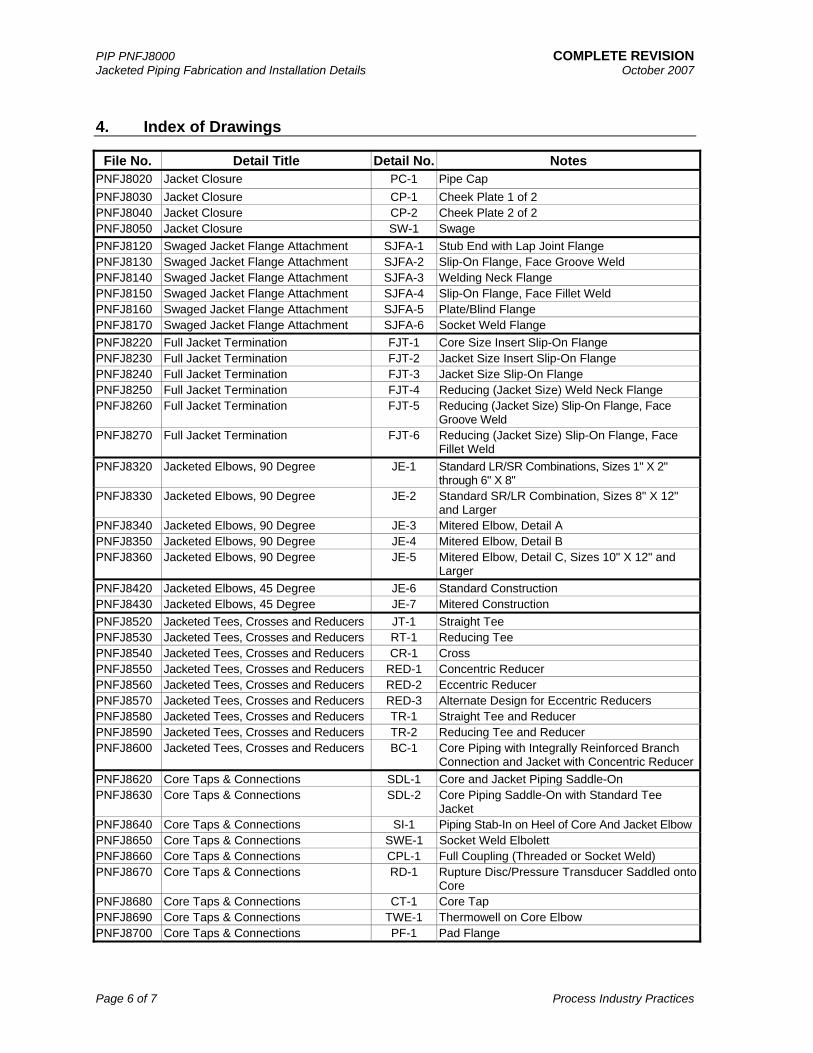
4. Index of Drawings
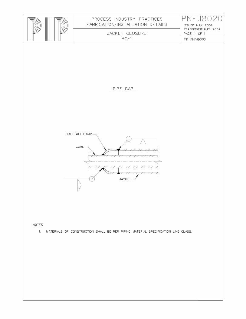
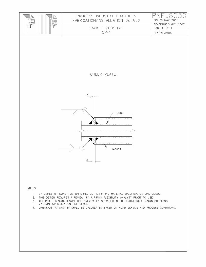
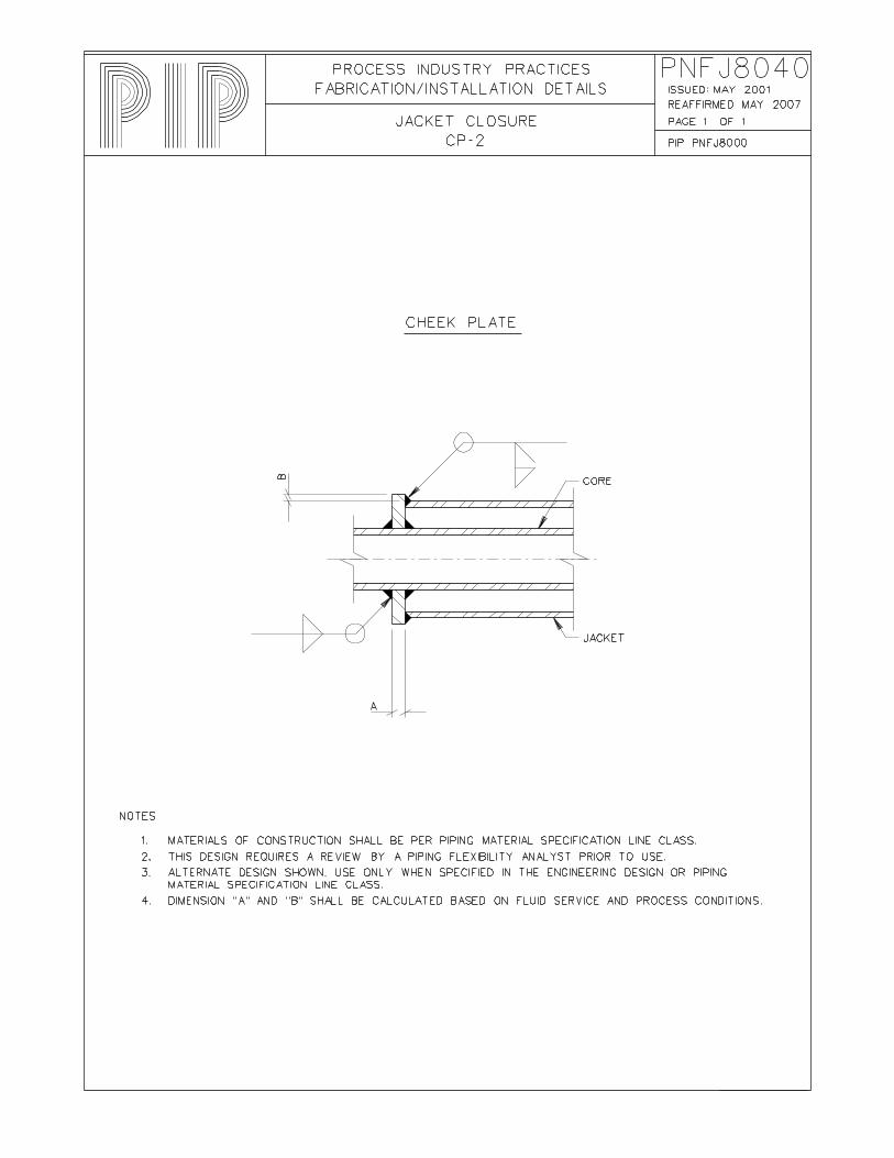
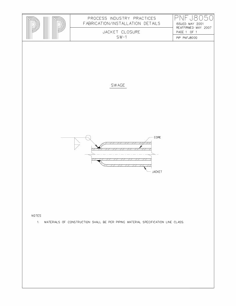
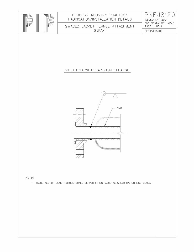
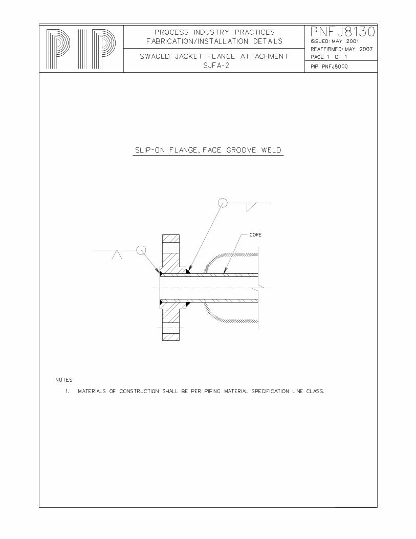
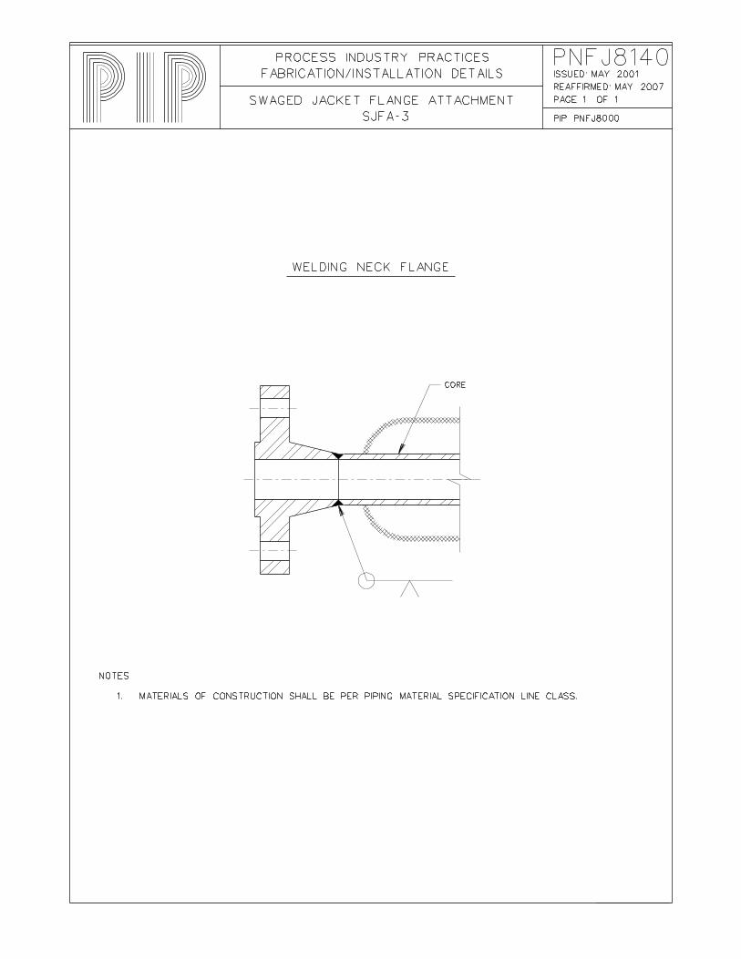
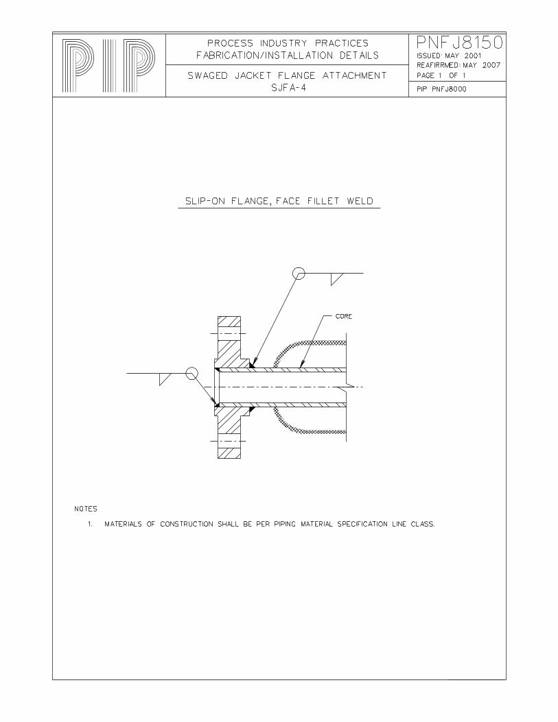
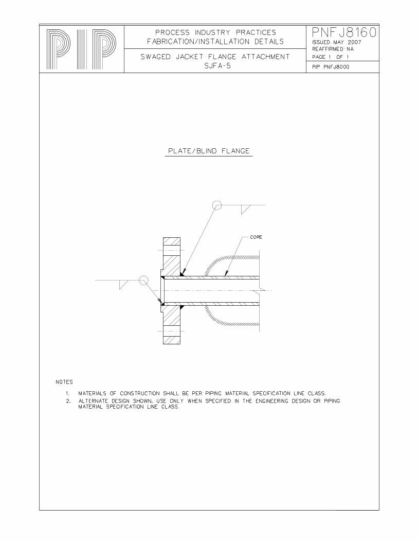
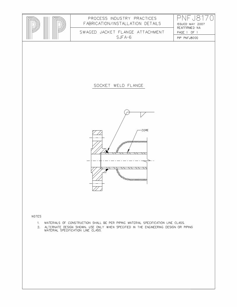
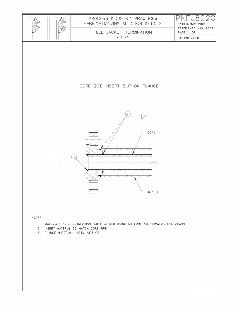
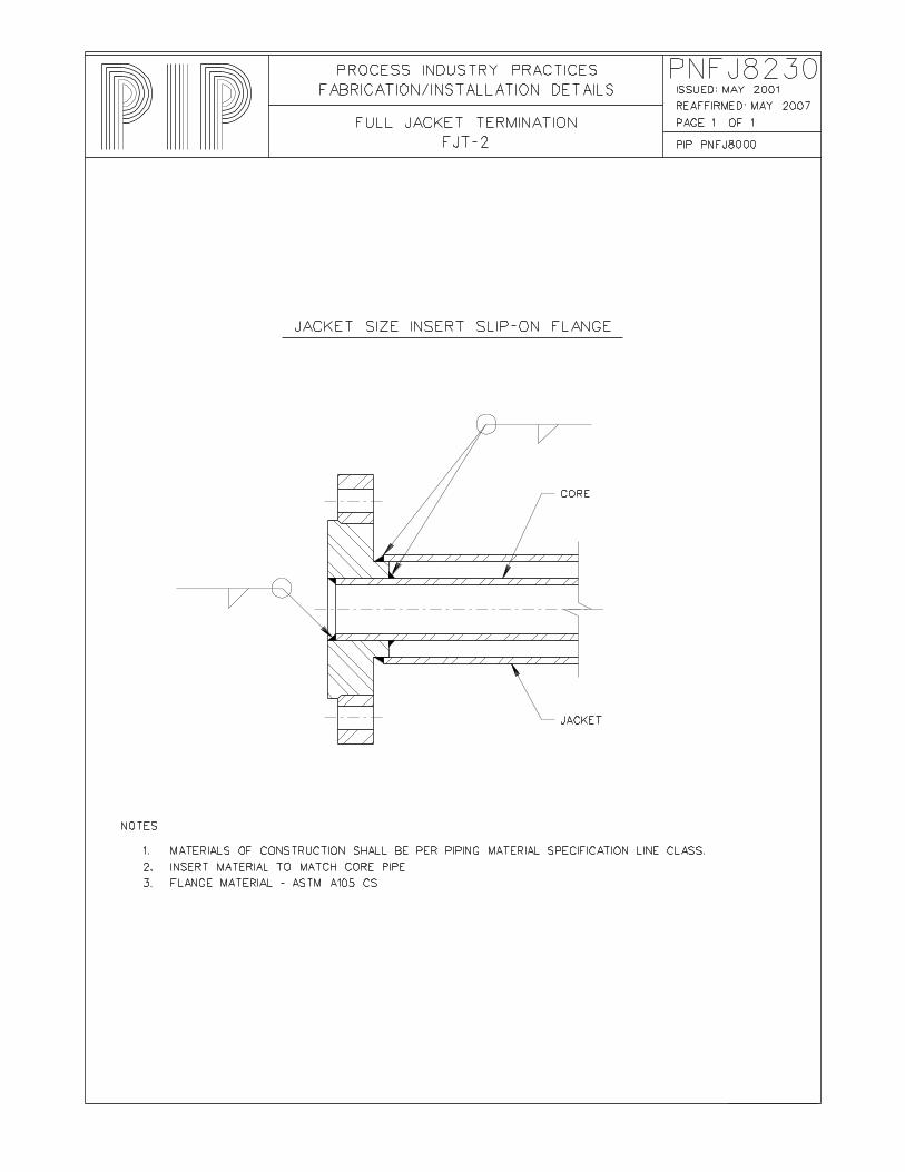
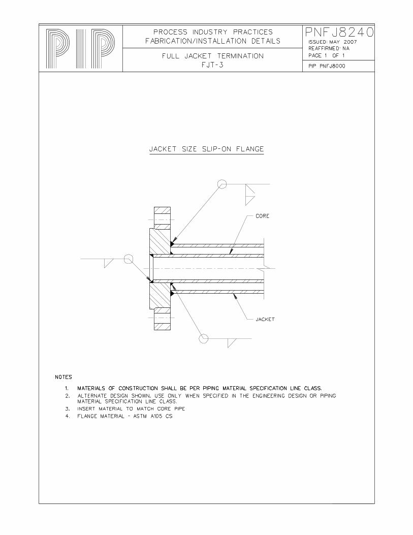
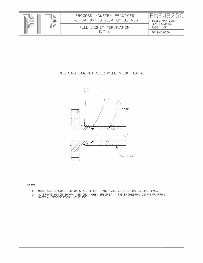
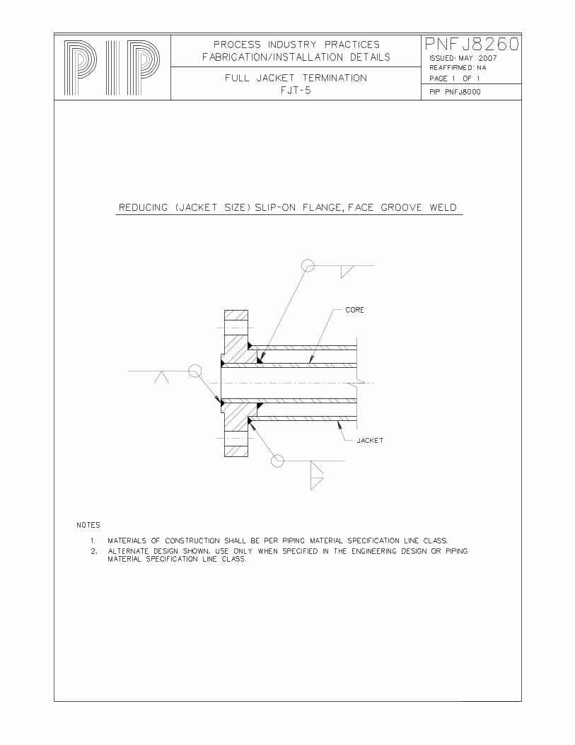
File No. Detail Title Detail No. Notes PNFJ8020 Jacket Closure PC-1 Pipe Cap PNFJ8030 Jacket Closure CP-1 Cheek Plate 1 of 2 PNFJ8040 Jacket Closure CP-2 Cheek Plate 2 of 2 PNFJ8050 Jacket Closure SW-1 Swage PNFJ8120 Swaged Jacket Flange Attachment SJFA-1 Stub End with Lap Joint Flange PNFJ8130 Swaged Jacket Flange Attachment SJFA-2 Slip-On Flange, Face Groove Weld PNFJ8140 Swaged Jacket Flange Attachment SJFA-3 Welding Neck Flange PNFJ8150 Swaged Jacket Flange Attachment SJFA-4 Slip-On Flange, Face Fillet Weld PNFJ8160 Swaged Jacket Flange Attachment SJFA-5 Plate/Blind Flange PNFJ8170 Swaged Jacket Flange Attachment SJFA-6 Socket Weld Flange PNFJ8220 Full Jacket Termination FJT-1 Core Size Insert Slip-On Flange PNFJ8230 Full Jacket Termination FJT-2 Jacket Size Insert Slip-On Flange PNFJ8240 Full Jacket Termination FJT-3 Jacket Size Slip-On Flange PNFJ8250 Full Jacket Termination FJT-4 Reducing (Jacket Size) Weld Neck Flange PNFJ8260 Full Jacket Termination FJT-5 Reducing (Jacket Size) Slip-On Flange, Face
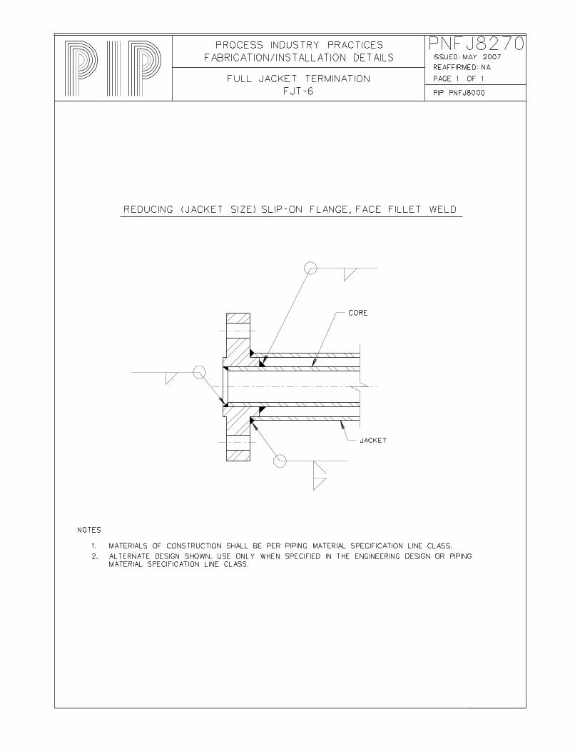
Groove Weld PNFJ8270 Full Jacket Termination FJT-6 Reducing (Jacket Size) Slip-On Flange, Face
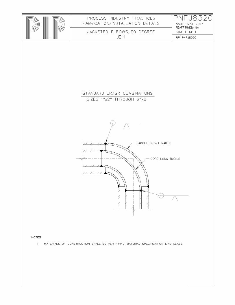
Fillet Weld PNFJ8320 Jacketed Elbows, 90 Degree JE-1 Standard LR/SR Combinations, Sizes 1" X 2"
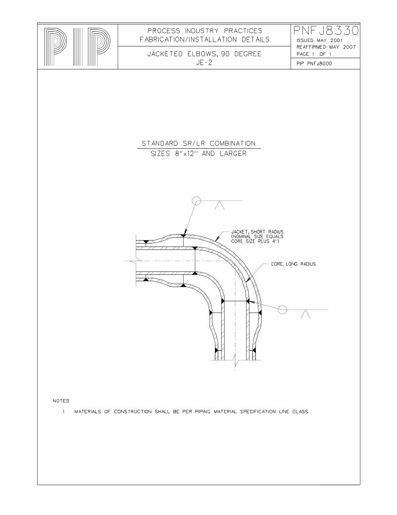
through 6" X 8" PNFJ8330 Jacketed Elbows, 90 Degree JE-2 Standard SR/LR Combination, Sizes 8" X 12"
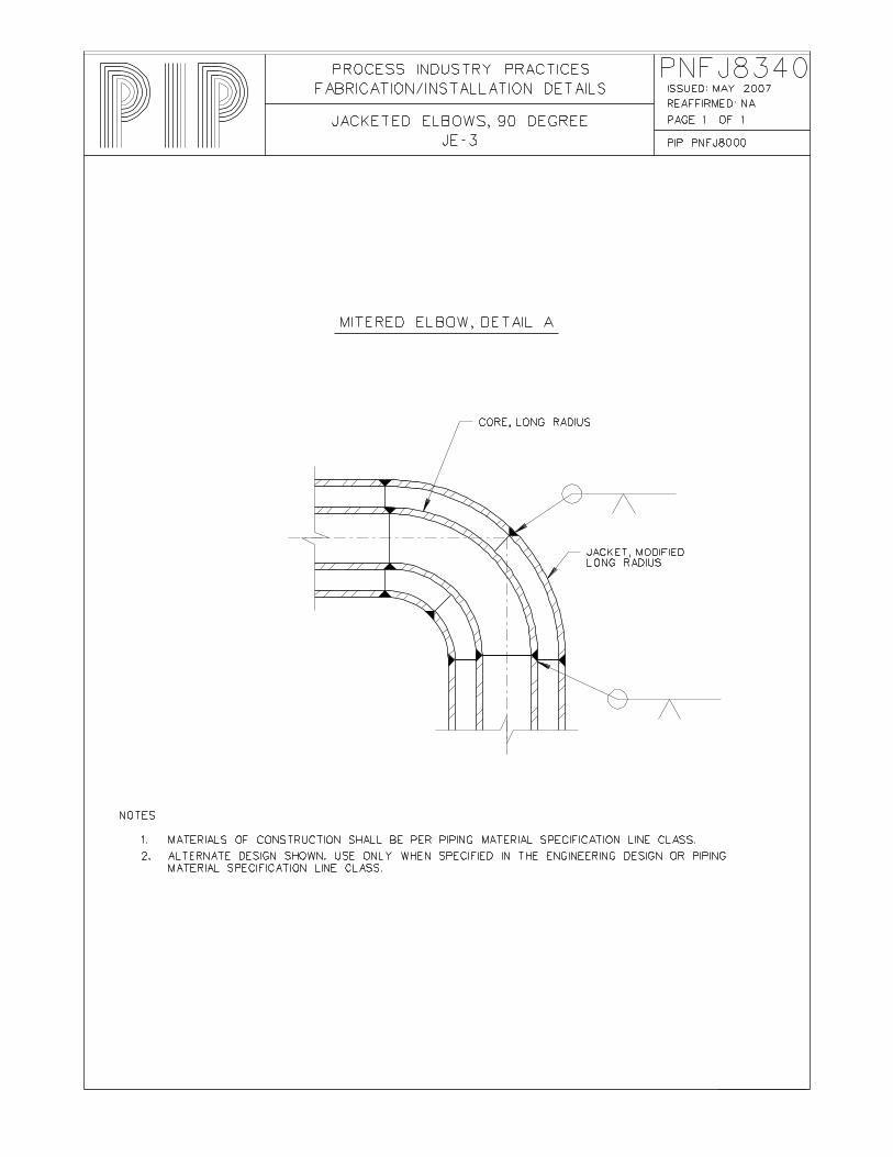
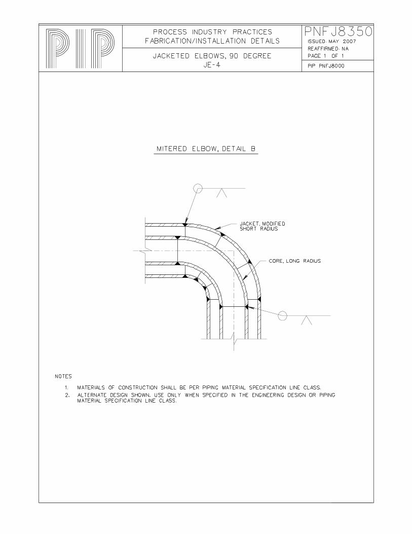
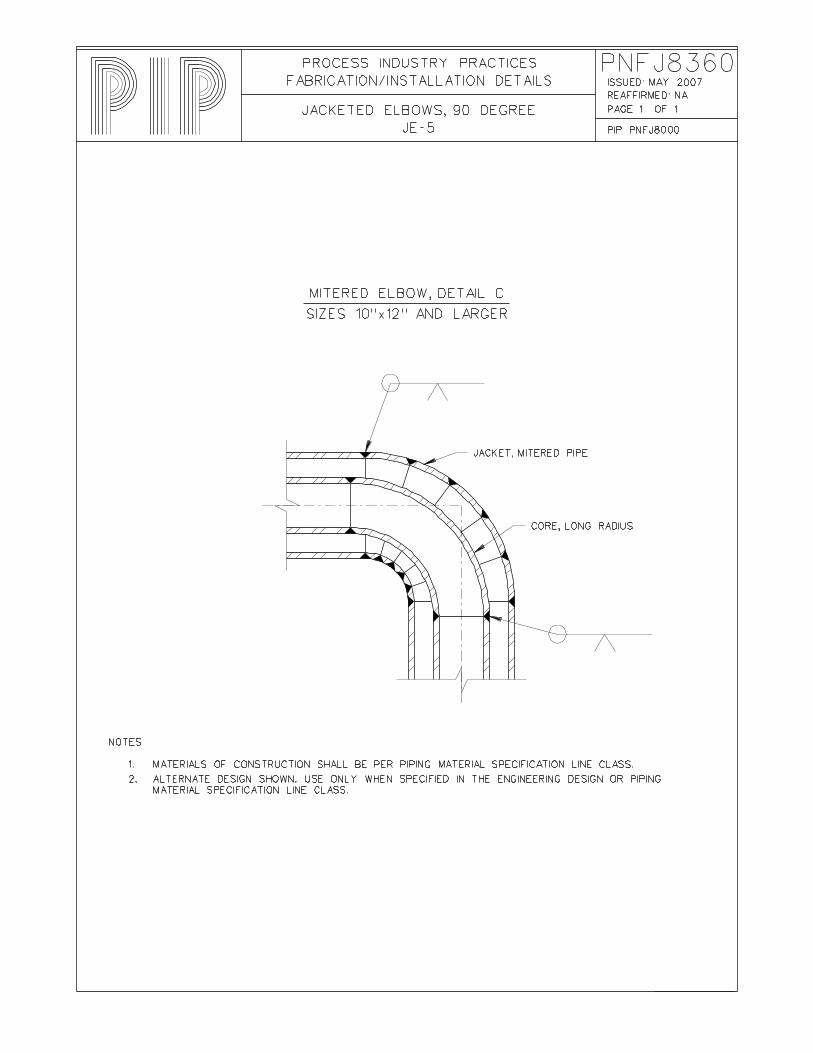
and Larger PNFJ8340 Jacketed Elbows, 90 Degree JE-3 Mitered Elbow, Detail A PNFJ8350 Jacketed Elbows, 90 Degree JE-4 Mitered Elbow, Detail B PNFJ8360 Jacketed Elbows, 90 Degree JE-5 Mitered Elbow, Detail C, Sizes 10" X 12" and
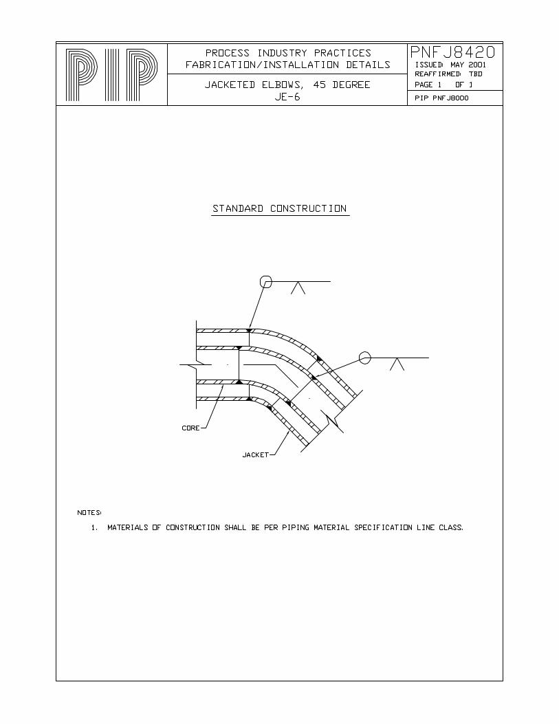
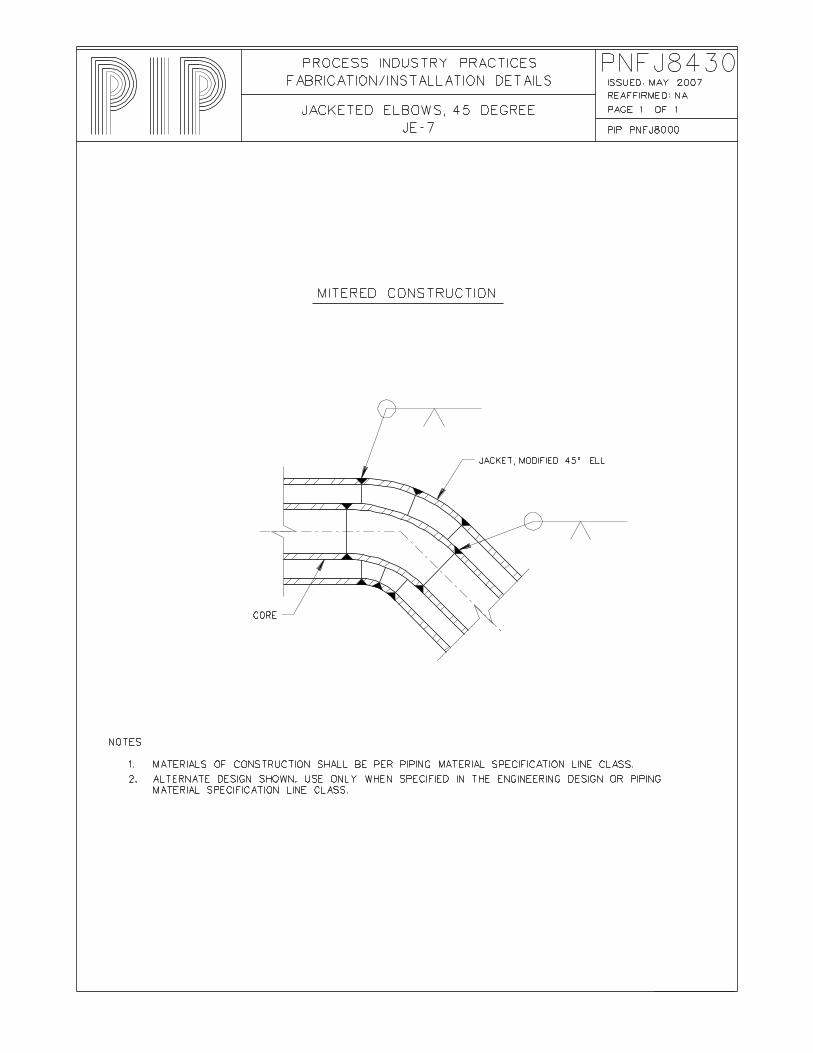
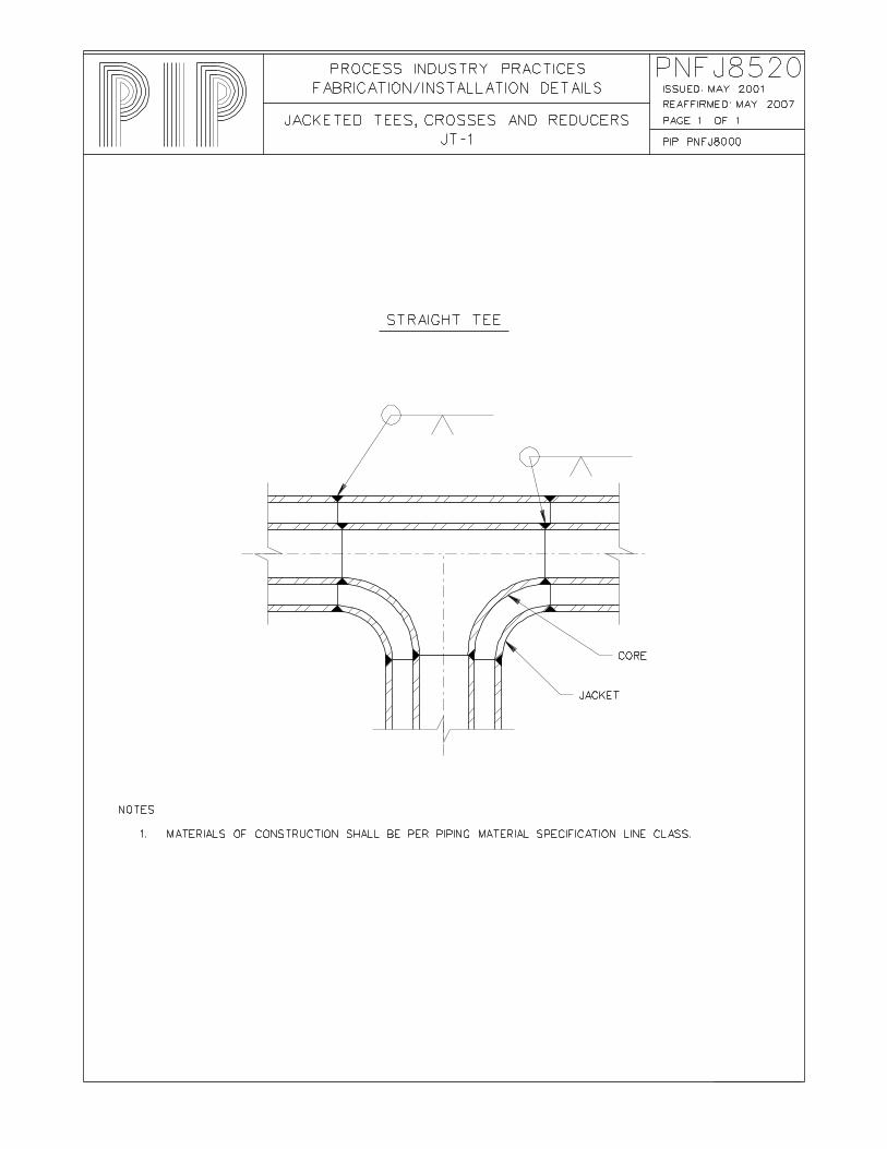
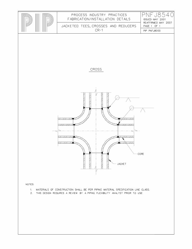
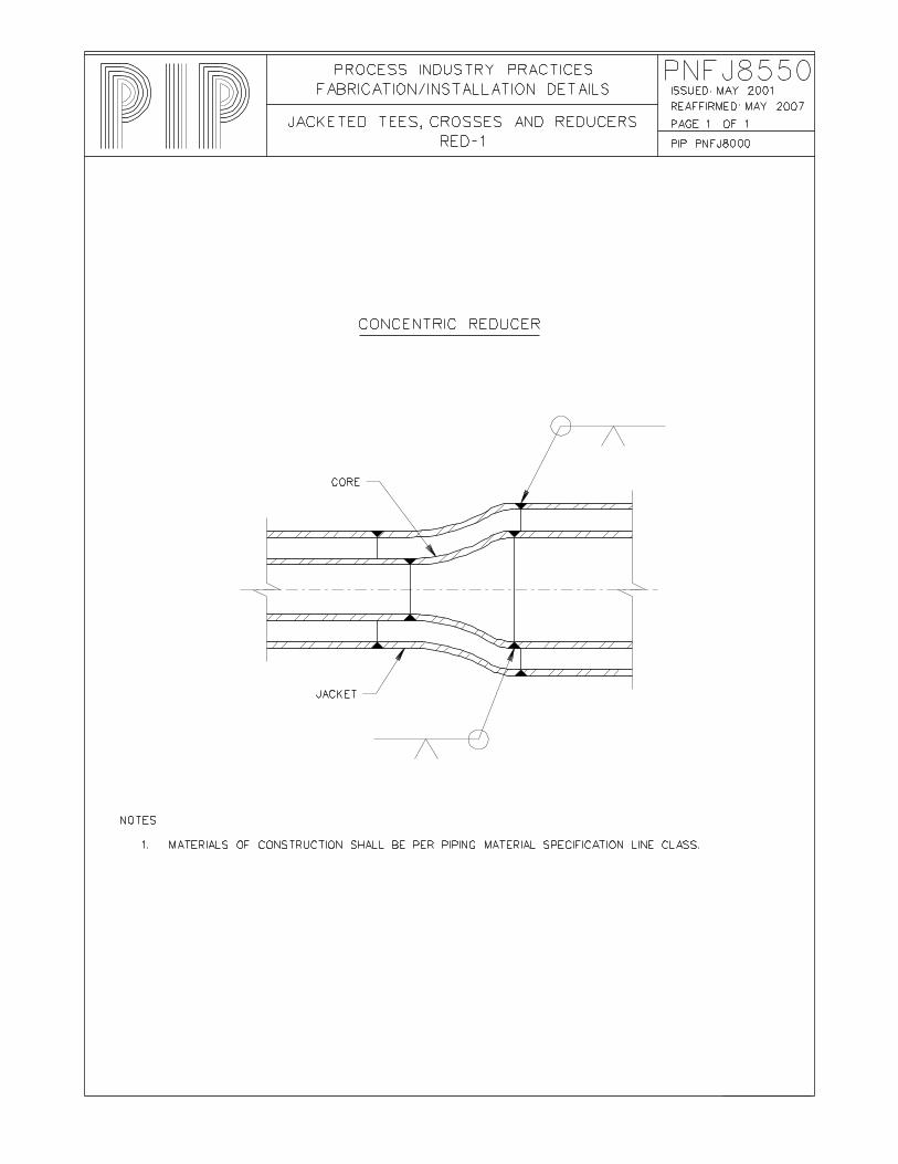
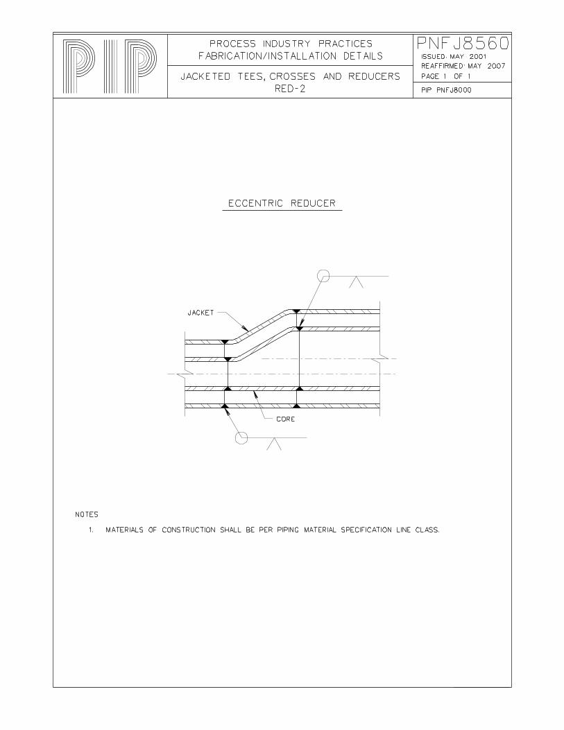
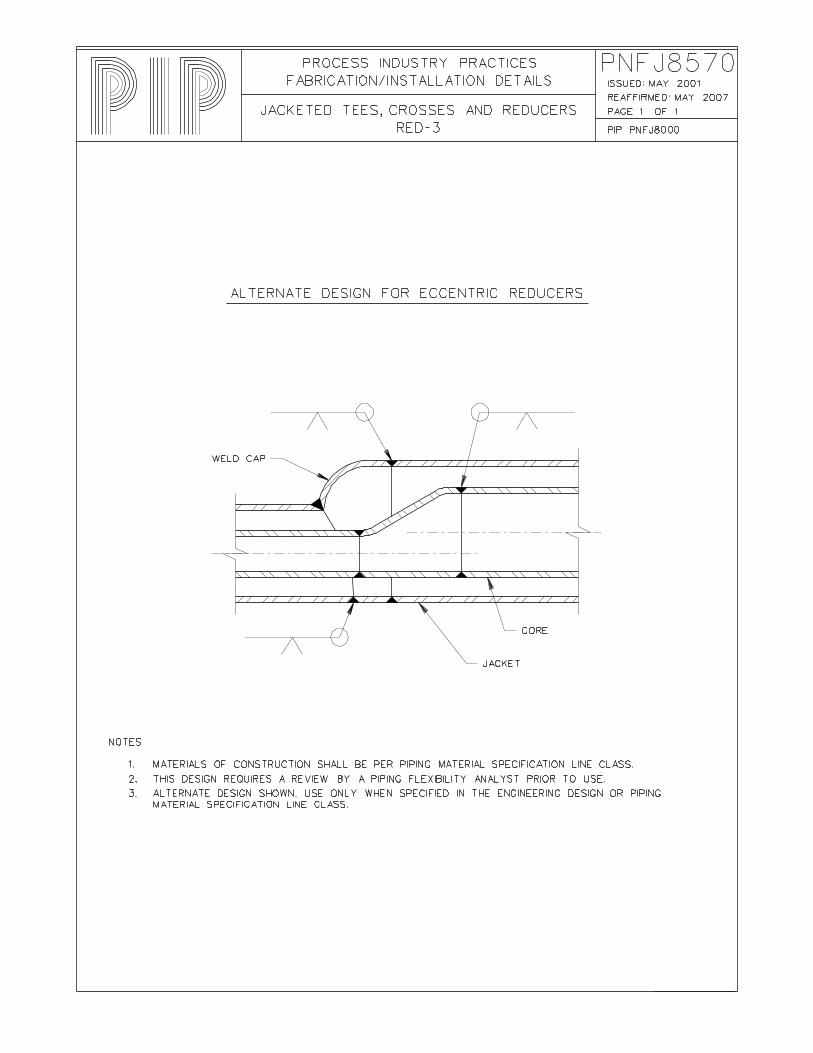
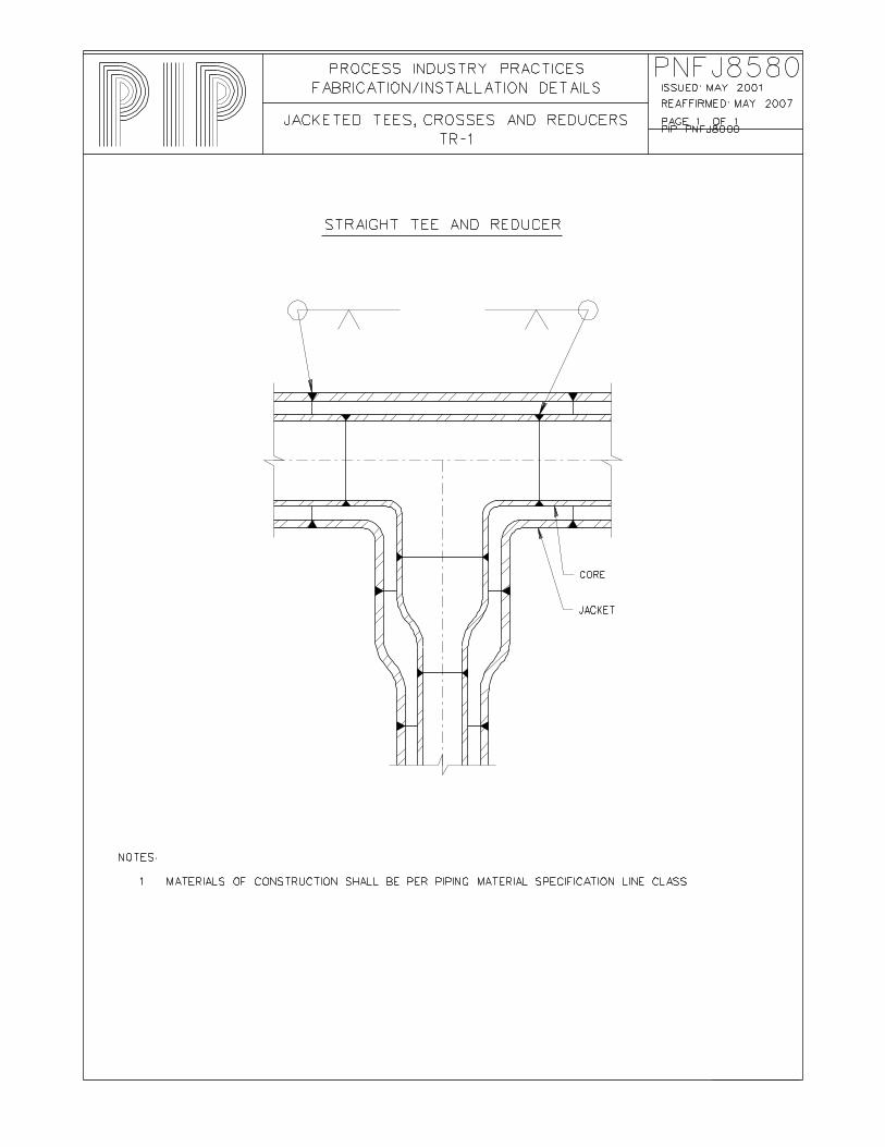
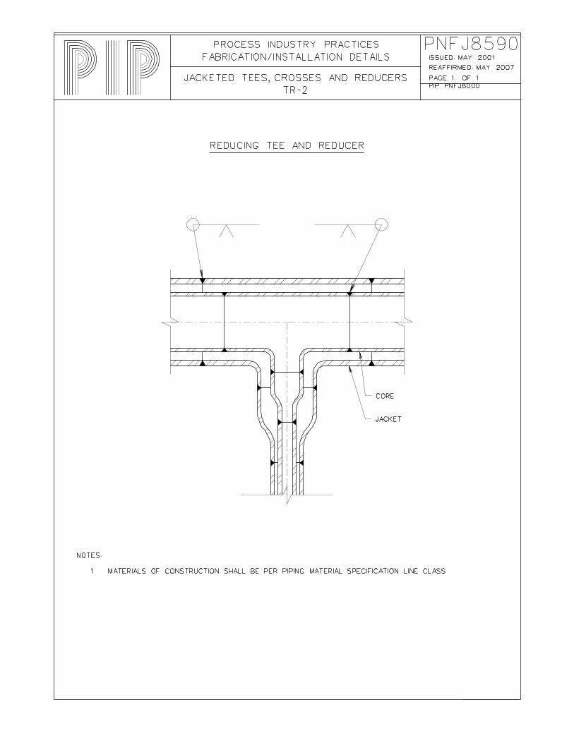
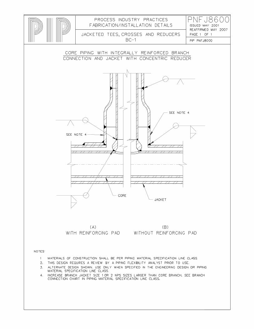
Larger PNFJ8420 Jacketed Elbows, 45 Degree JE-6 Standard Construction PNFJ8430 Jacketed Elbows, 45 Degree JE-7 Mitered Construction PNFJ8520 Jacketed Tees, Crosses and Reducers JT-1 Straight Tee PNFJ8530 Jacketed Tees, Crosses and Reducers RT-1 Reducing Tee PNFJ8540 Jacketed Tees, Crosses and Reducers CR-1 Cross PNFJ8550 Jacketed Tees, Crosses and Reducers RED-1 Concentric Reducer PNFJ8560 Jacketed Tees, Crosses and Reducers RED-2 Eccentric Reducer PNFJ8570 Jacketed Tees, Crosses and Reducers RED-3 Alternate Design for Eccentric Reducers PNFJ8580 Jacketed Tees, Crosses and Reducers TR-1 Straight Tee and Reducer PNFJ8590 Jacketed Tees, Crosses and Reducers TR-2 Reducing Tee and Reducer PNFJ8600 Jacketed Tees, Crosses and Reducers BC-1 Core Piping with Integrally Reinforced Branch
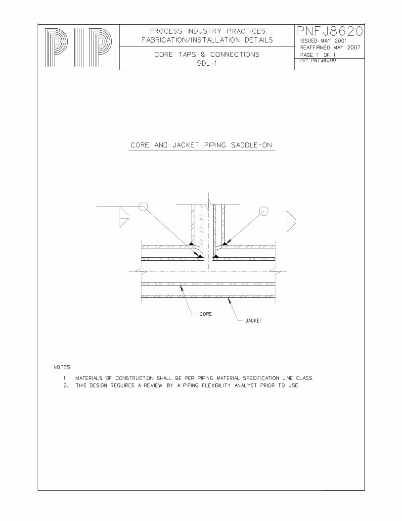
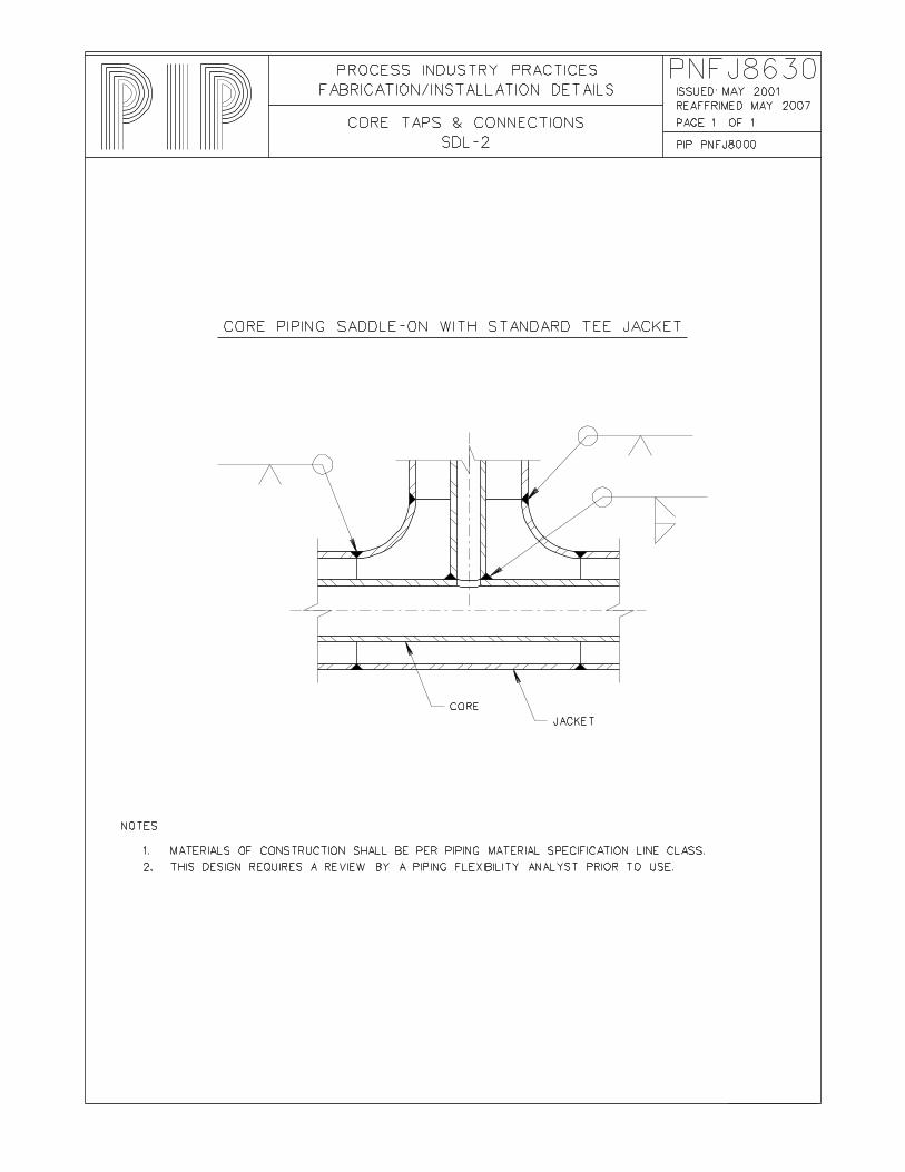
Connection and Jacket with Concentric ReducerPNFJ8620 Core Taps & Connections SDL-1 Core and Jacket Piping Saddle-On PNFJ8630 Core Taps & Connections SDL-2 Core Piping Saddle-On with Standard Tee
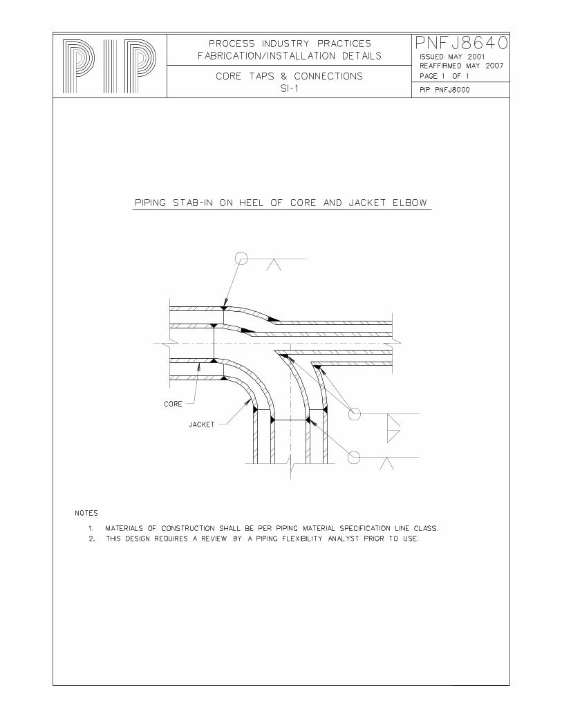
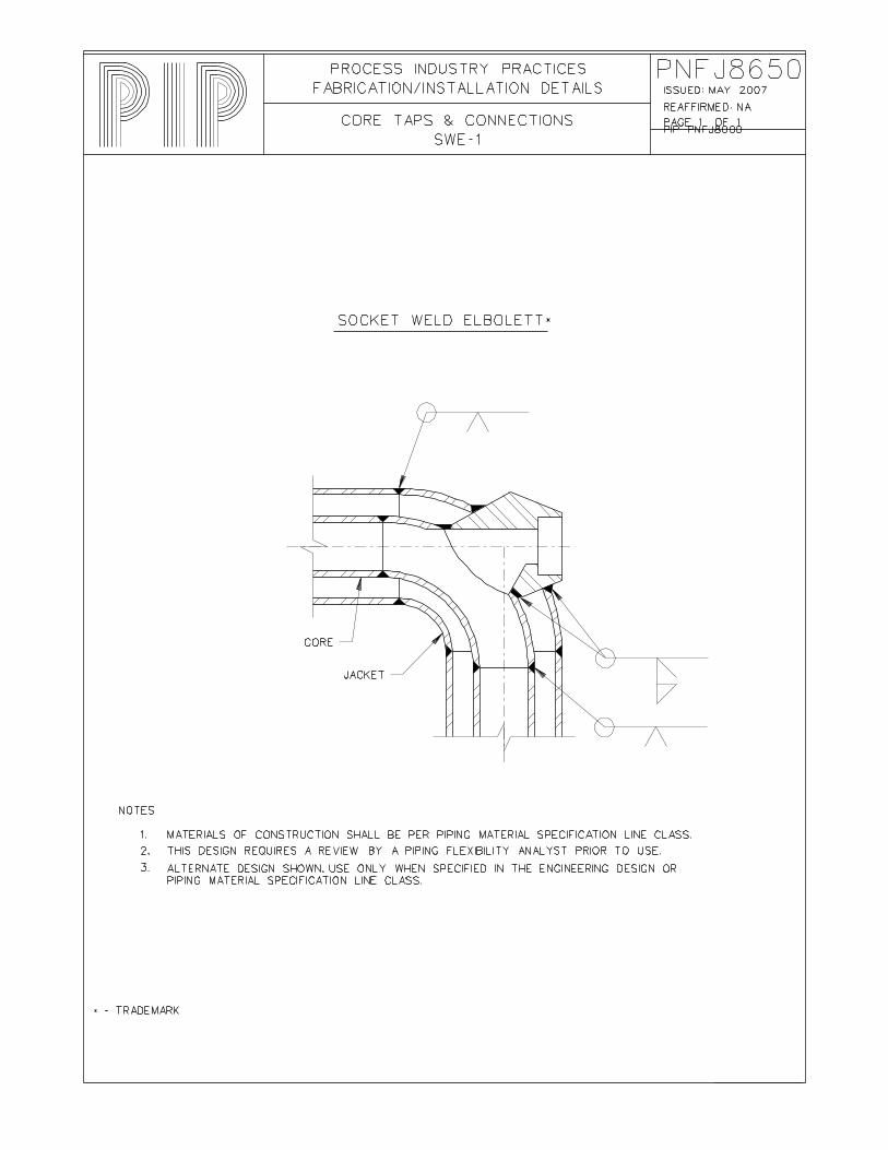
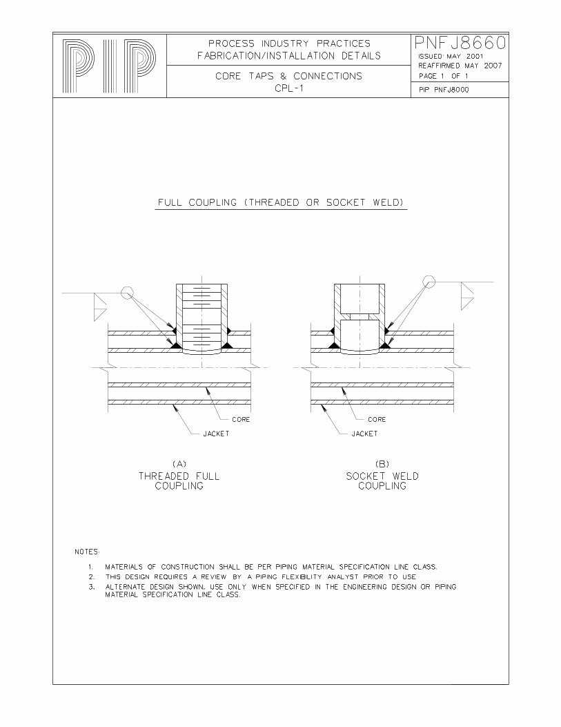
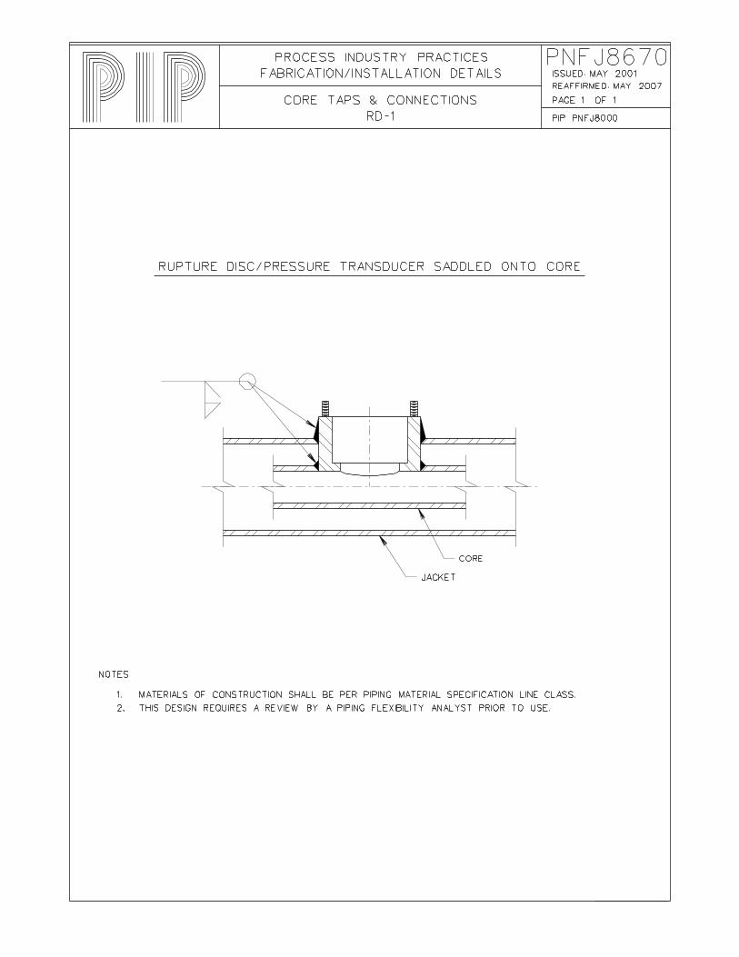
Jacket PNFJ8640 Core Taps & Connections SI-1 Piping Stab-In on Heel of Core And Jacket Elbow PNFJ8650 Core Taps & Connections SWE-1 Socket Weld Elbolett PNFJ8660 Core Taps & Connections CPL-1 Full Coupling (Threaded or Socket Weld) PNFJ8670 Core Taps & Connections RD-1 Rupture Disc/Pressure Transducer Saddled onto
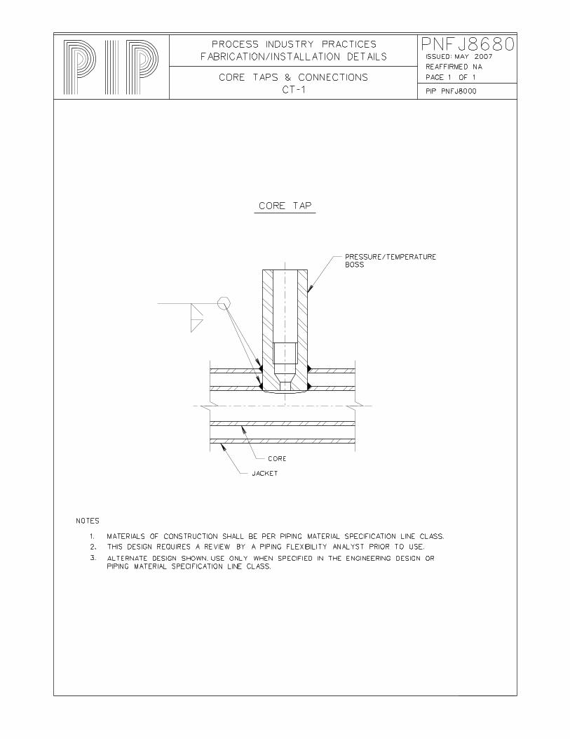
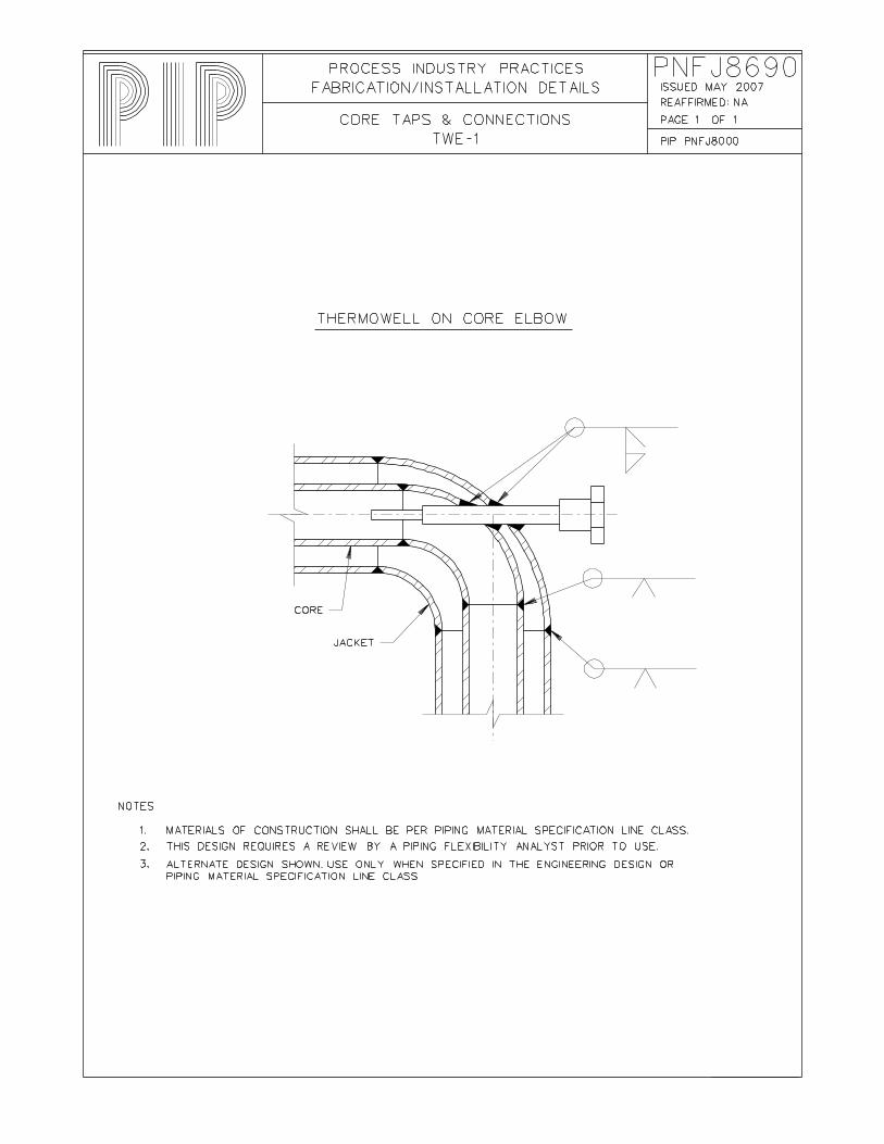
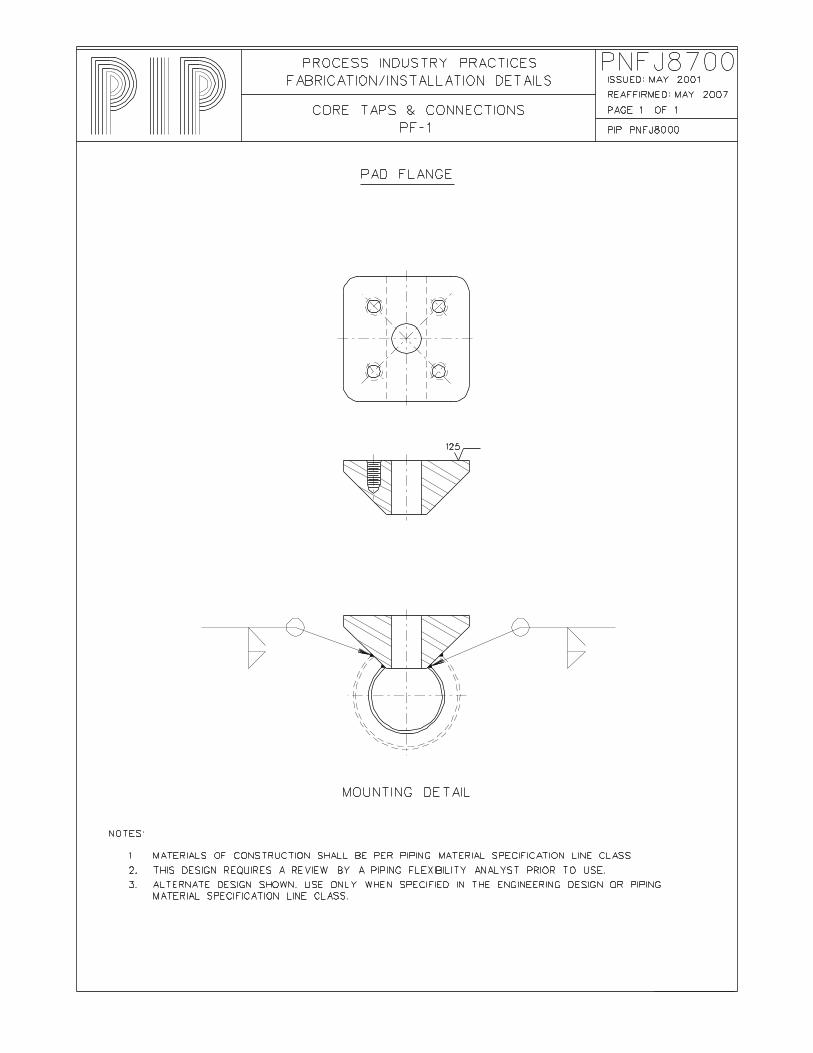
Core PNFJ8680 Core Taps & Connections CT-1 Core Tap PNFJ8690 Core Taps & Connections TWE-1 Thermowell on Core Elbow PNFJ8700 Core Taps & Connections PF-1 Pad Flange
Page 6 of 7 Process Industry Practices
COMPLETE REVISION PIP PNFJ8000 October 2007 Jacketed Piping Fabrication and Installation Details
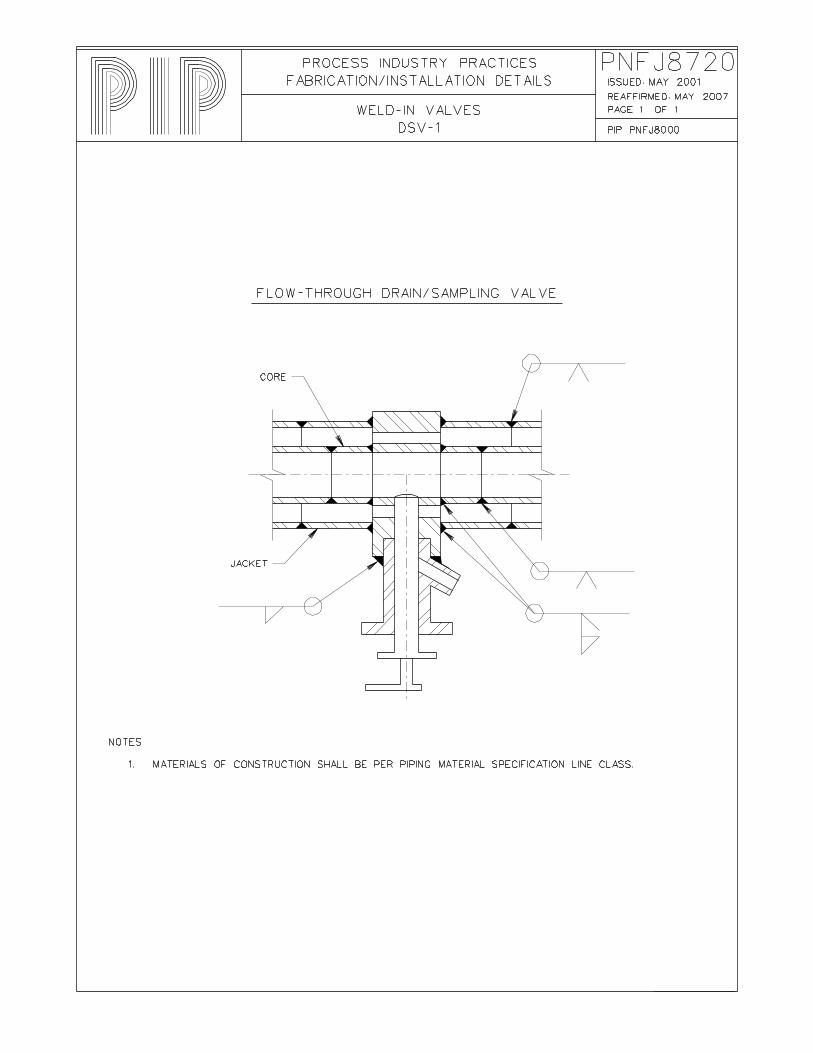
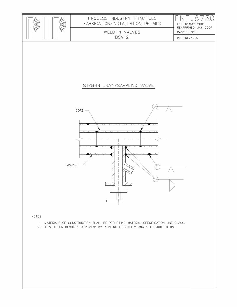
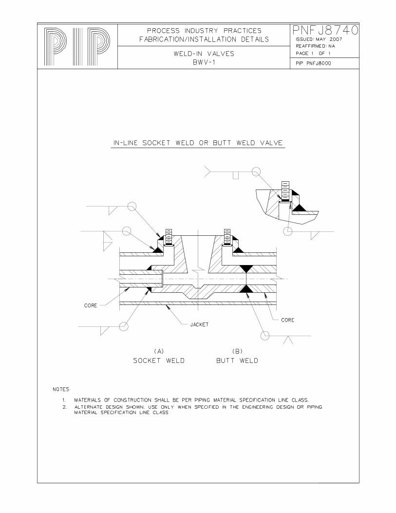
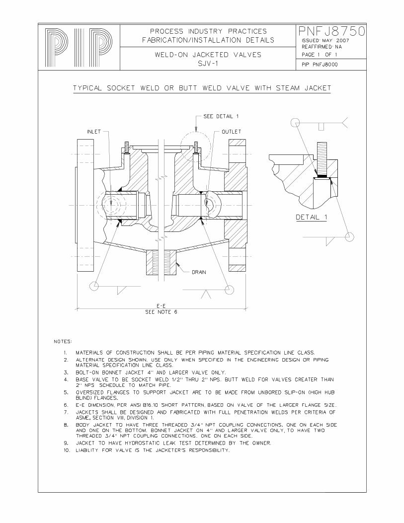
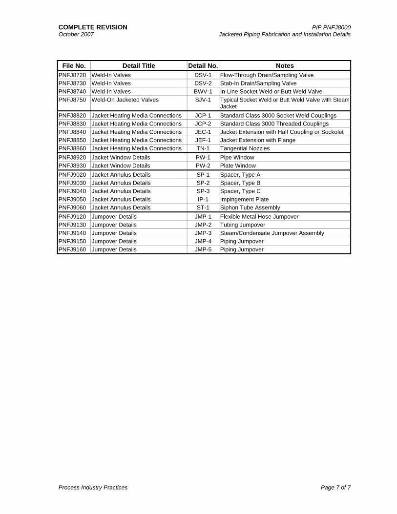
File No. Detail Title Detail No. Notes PNFJ8720 Weld-In Valves DSV-1 Flow-Through Drain/Sampling Valve PNFJ8730 Weld-In Valves DSV-2 Stab-In Drain/Sampling Valve PNFJ8740 Weld-In Valves BWV-1 In-Line Socket Weld or Butt Weld Valve PNFJ8750 Weld-On Jacketed Valves SJV-1 Typical Socket Weld or Butt Weld Valve with Steam
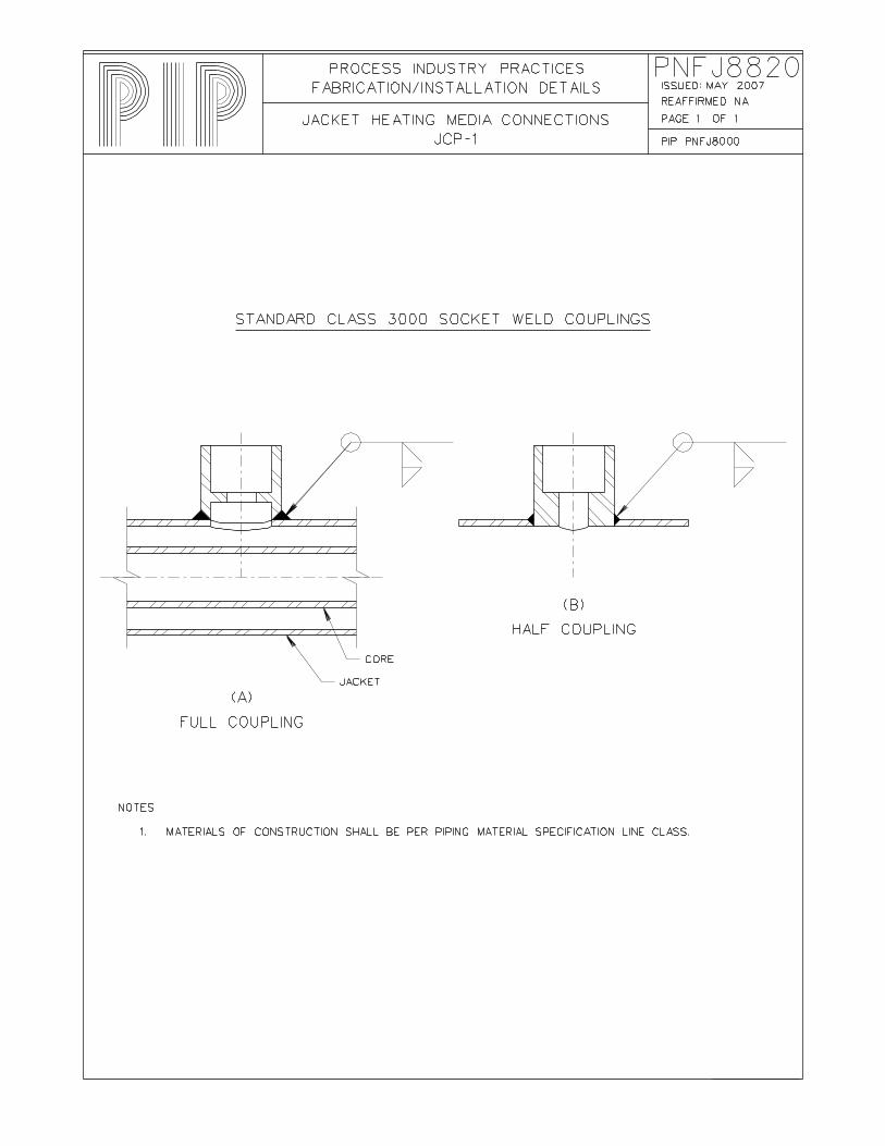
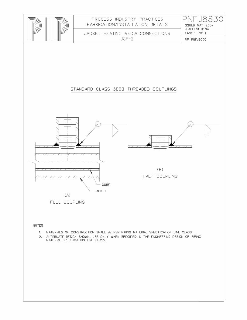
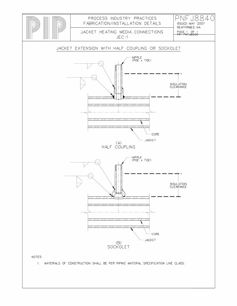
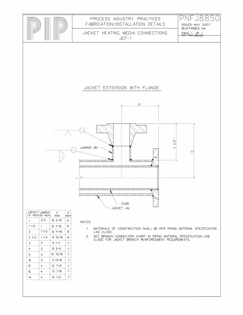
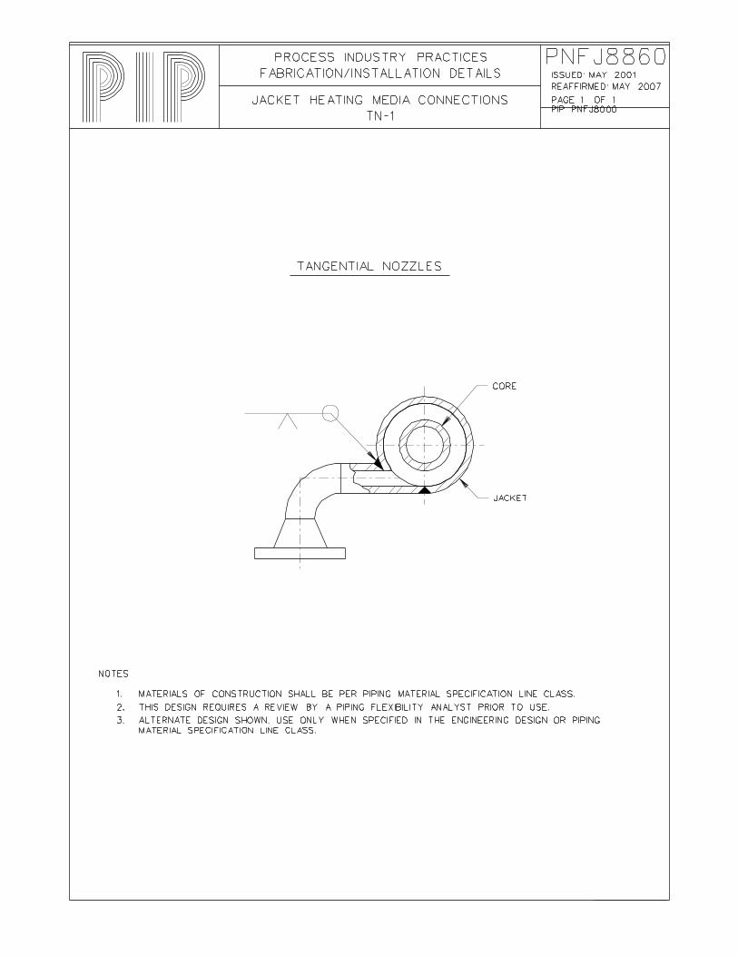
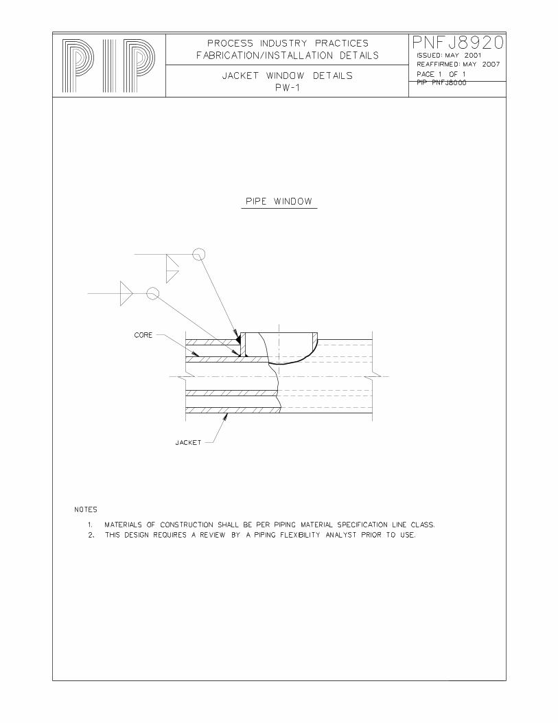
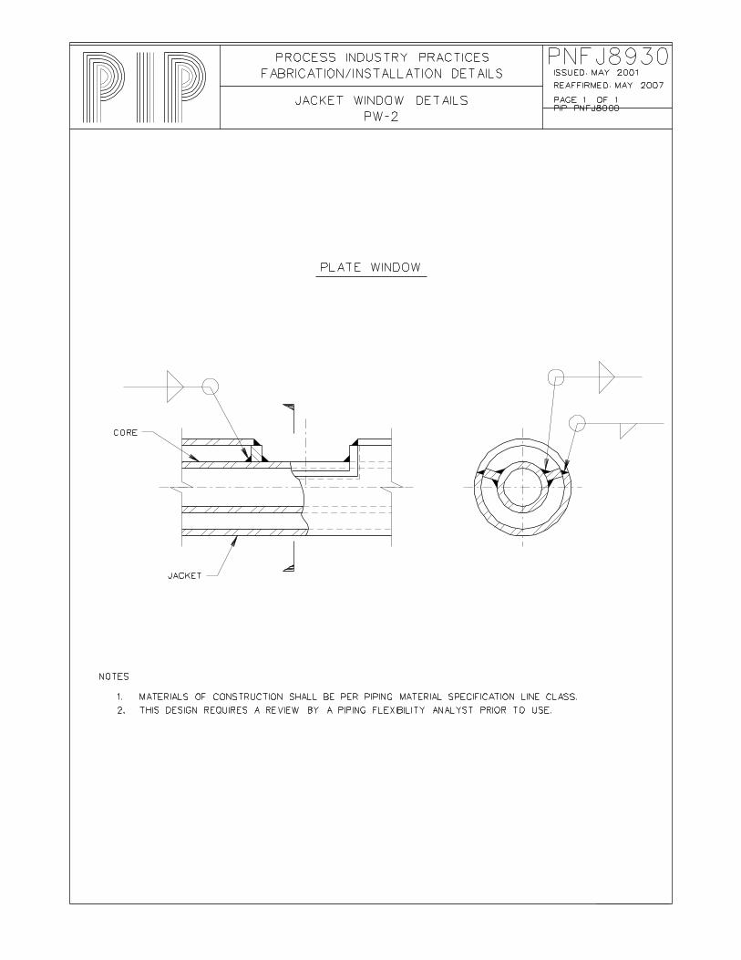
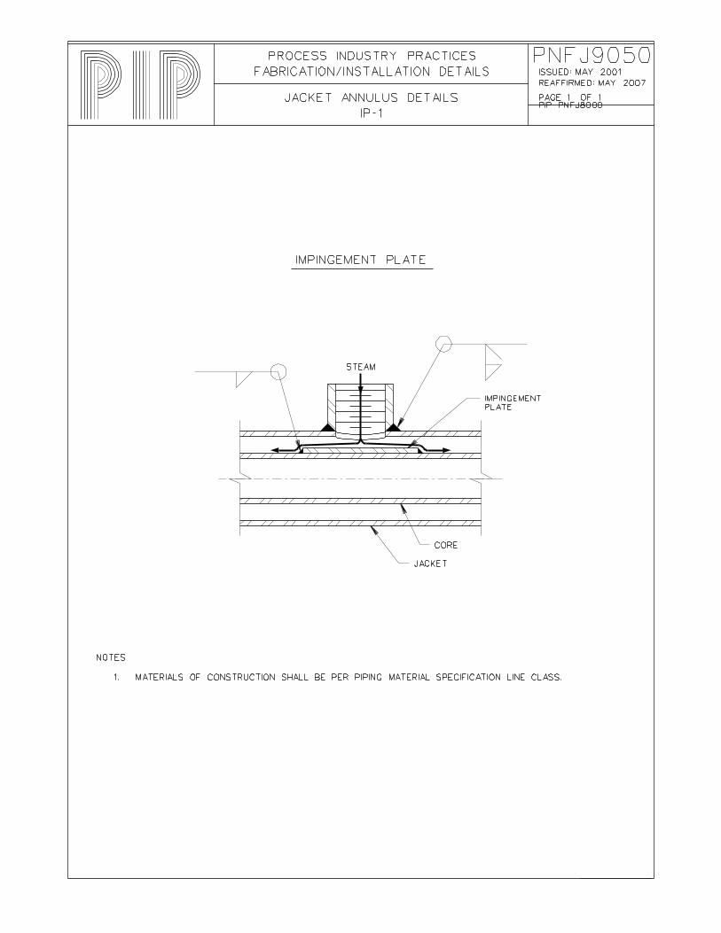
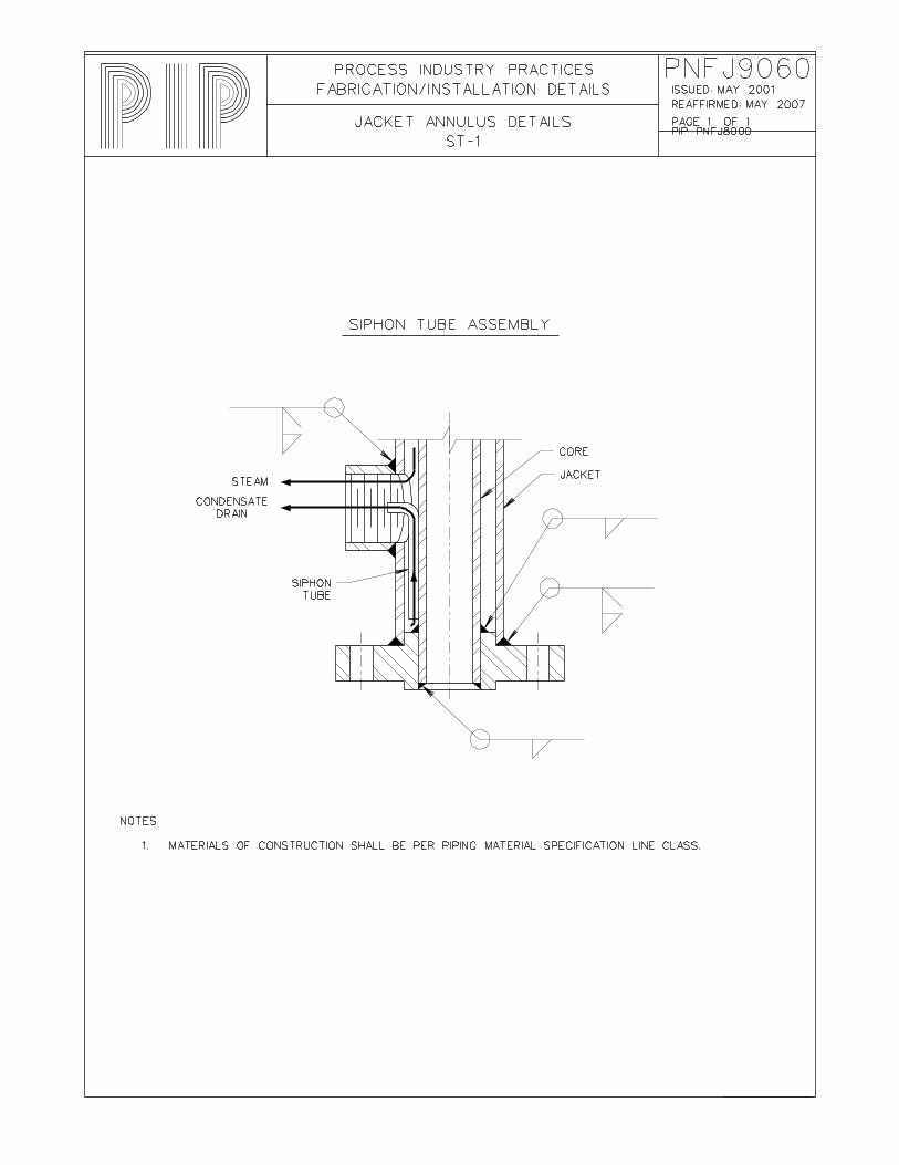
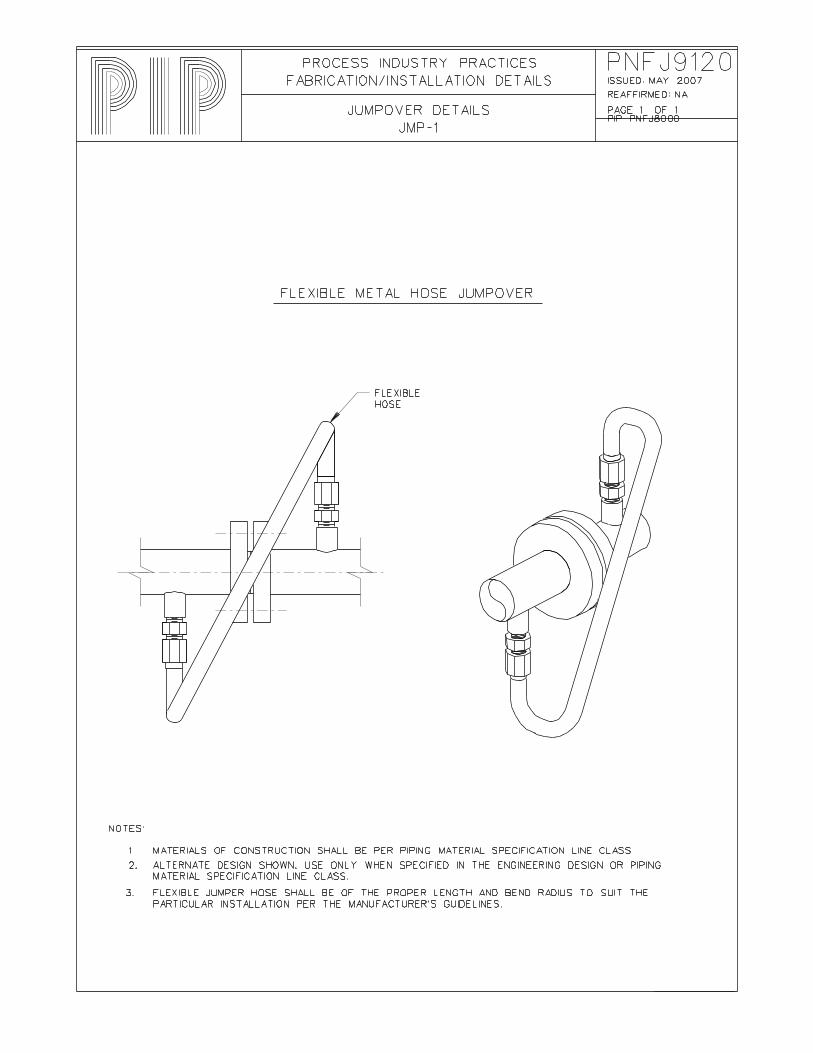
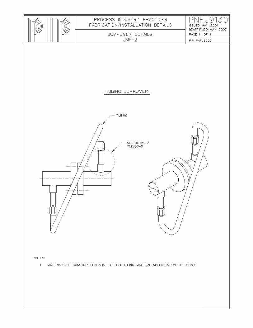
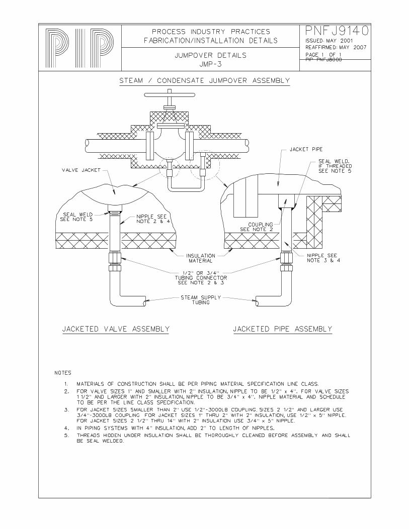
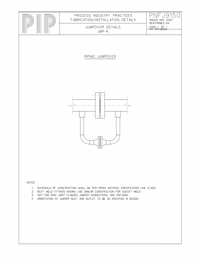
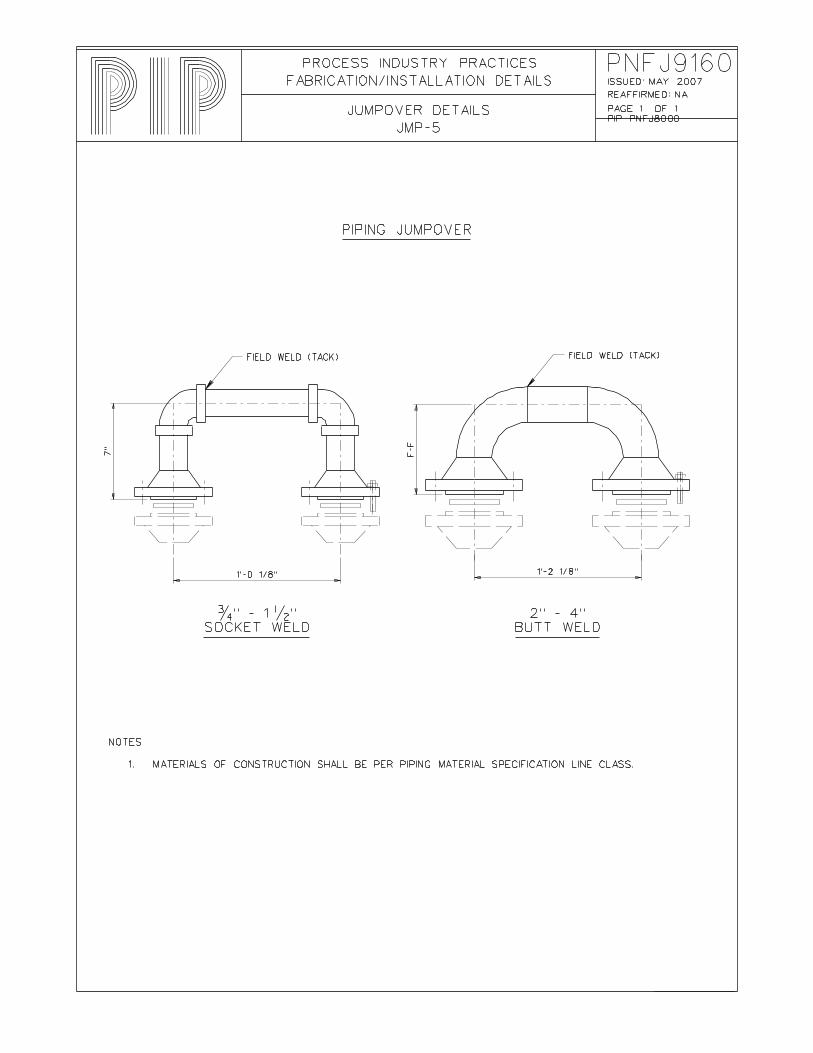
Jacket PNFJ8820 Jacket Heating Media Connections JCP-1 Standard Class 3000 Socket Weld Couplings PNFJ8830 Jacket Heating Media Connections JCP-2 Standard Class 3000 Threaded Couplings PNFJ8840 Jacket Heating Media Connections JEC-1 Jacket Extension with Half Coupling or Sockolet PNFJ8850 Jacket Heating Media Connections JEF-1 Jacket Extension with Flange PNFJ8860 Jacket Heating Media Connections TN-1 Tangential Nozzles PNFJ8920 Jacket Window Details PW-1 Pipe Window PNFJ8930 Jacket Window Details PW-2 Plate Window PNFJ9020 Jacket Annulus Details SP-1 Spacer, Type A PNFJ9030 Jacket Annulus Details SP-2 Spacer, Type B PNFJ9040 Jacket Annulus Details SP-3 Spacer, Type C PNFJ9050 Jacket Annulus Details IP-1 Impingement Plate PNFJ9060 Jacket Annulus Details ST-1 Siphon Tube Assembly PNFJ9120 Jumpover Details JMP-1 Flexible Metal Hose Jumpover PNFJ9130 Jumpover Details JMP-2 Tubing Jumpover PNFJ9140 Jumpover Details JMP-3 Steam/Condensate Jumpover Assembly PNFJ9150 Jumpover Details JMP-4 Piping Jumpover PNFJ9160 Jumpover Details JMP-5 Piping Jumpover
Process Industry Practices Page 7 of 7