proceedings of the freenix track: 2003 usenix … · usenix association freenix track: 2003 usenix...
TRANSCRIPT
USENIX Association
Proceedings of theFREENIX Track:
2003 USENIX AnnualTechnical Conference
San Antonio, Texas, USAJune 9-14, 2003
THE ADVANCED COMPUTING SYSTEMS ASSOCIATION
© 2003 by The USENIX Association All Rights Reserved For more information about the USENIX Association:
Phone: 1 510 528 8649 FAX: 1 510 548 5738 Email: [email protected] WWW: http://www.usenix.orgRights to individual papers remain with the author or the author's employer.
Permission is granted for noncommercial reproduction of the work for educational or research purposes.
This copyright notice must be included in the reproduced paper. USENIX acknowledges all trademarks herein.

FREENIX Track: 2003 USENIX Annual Technical ConferenceUSENIX Association 219
Building a Wireless Community Network in the Netherlands
Rudi van DrunenWirelessLeiden Foundation
Leiden, the [email protected]
http://www.wirelessleiden.nl
Dirk-Willem van GulikWirelessLeiden [email protected]
Jasper KoolhaasWirelessLeiden Foundation
Huub SchuurmansWirelessLeiden [email protected]
Marten VijnWirelessLeiden Foundation
Abstract
With the development of low cost hardware based onIEEE 802.11b, wireless networks are an emerging tech-nology. Using these wireless techniques outdoors it ispossible to build a community network not dependenton any provider. In the Netherlands such a network isbeing set up in and around Leiden. Using low cost net-work interfaces, home-built antennas and open sourcesoftware the volunteers of the Wireless Leiden Founda-tion were able to lay out an infrastructure for the inhabi-tants of Leiden at a very low cost. All kinds of applica-tions (for-proÞt and not-for-proÞt) are using this wirelessnetwork.
1 IntroductionCurrent computer networks generally rely on a perma-nent, Þxed and largely wired infrastructure which isowned and often operated by large entities such as tele-com operators. A relatively new and emerging technol-ogy is wireless Ethernet, or wireless networking usingthe IEEE 802.11 standard. This standard encompassesthe lower layers of the OSI model for transport of dataas Ethernet frames using a spread spectrum based radiolink.
This opens the possibility of building a network with-out having the problems and the cost associated withputting some sort of physical transmission medium inthe ground. Instead, antennas can be used to send andreceive the data using radio waves through free air.
Because of the relative simplicity of the currentlyavailable commodity hardware that uses 802.11 technol-ogy, it is relatively easy to build a local wireless com-munity network in a town. Using this network peoplecan share resources with each other. Examples are shar-ing sound or video Þles with the local museums, or hav-
ing data (text, images, video, audio Þles) provided bythe local government on-line. Furthermore, the networkcan connect to the Internet providing a low cost way ofcrossing the last mile to the user at high bandwidth.
In Leiden, the Netherlands, a foundation has been es-tablished by a number of knowledgeable volunteers withthe intention to build a network operated and owned by acommunity of users, not by big entities such as telcos orInternet Service Providers (ISPs). This essentially freenetwork infrastructure can be used by anyone presentin the service area for running his or her own applica-tion. On the client platform only an industry standardIEEE 802.11b interface and a probably small antennais needed. Usage of the infrastructure is not Óanothermonthly billÓ, but will be free, after a one time up-frontinvestment in equipment.
2 Method
2.1 Introduction
The wireless community network built has to meet anumber of requirements to be successful. First of allit has to be as ÒopenÓ as possible to the users and tothe developers. Being ÒopenÓ enables anyone within thecommunity to actively use the network and participate inthe building thereof. Another constraint is that the net-work should be both reliable and low-cost. These con-straints are met in this design using commercial off theshelf (COTS) and home built (low cost) hardware (net-work boards, antennas and PC hardware) componentsand Open Source software (such as Linux, FreeBSD andother packages well known to the Free Software com-munity).

FREENIX Track: 2003 USENIX Annual Technical Conference USENIX Association220
2.2 TechnologiesA number of different technologies are available to buildwireless computer networks. Most commercial solutionsare proprietary to certain vendors or do not use low costhardware.
The IEEE 802.11 standard (called WiFi in the com-mercial world) allows users to network their machinesusing radio technology. Different sub-standards havebeen formed specifying the bandwidth or radio fre-quency the networks operate on. The standard de-Þnes a number of operation modes which allow for ad-hoc, point to point and point to multi point networking.Though the standard calls for two transmission technol-ogy standards: Direct Spread Spectrum (DSS) and Fre-quency Hopping Spread Spectrum (FHSS), the markethas by and large standardized on DSS for indoor andoutdoor point to multi-point use. FHSS, which is morerobust against certain types of interference and denselypacked endpoints, is currently only seen on long pointto point connections where interference and frequencyallocations are at a premium, for example, at an aggre-gation point.
In this project we have chosen the 802.11b as primarystandard mostly because of the availability of equip-ment, open source drivers and the cost of the hardware.IEEE 802.11b is a DSS radio technology supporting linkspeeds of 1,2,5.5 and 11 Mbit/s. The standard uses the2.4 GHz frequency band and is initially designed forhome and ofÞce use but with special measures (anten-nas) it is also applicable to crossing longer distances out-doors (up to a maximum of approximately 15 Km line ofsight). [WirelessNet, WirelessComm]
2.3 TopologyThe network we are building and operating is targeted toa coverage area of 25Km2, which is the complete cityof Leiden (The Netherlands) and its surroundings. Thereare no hills in the target area. Other natural obstaclessuch as large forests are also absent. It is a small oldtown center with some moderately high buildings andsome 10-15 story appartment buildings in the suburbs.These appartment ßats are surrounded by small houses(max. height 3 ßoors).
The total number of people living in this area is ap-proximately 160,000. In this area we want to provideoutdoor coverage. For using the network indoors, asmall antenna connected to the client computer has tobe sufÞcient. The antenna should preferably have a lineof sight to the nearest network access point. This isrequired as the maximum distance between the clientand the network access point (a network node) is lim-ited due to the national legislation implementing Euro-pean (EU / ERC) regulations (restricting maximum radiofrequency output power and restricting antenna gain).
Combining this knowledge with the anticipated trafÞcand bandwidth needs, it is evident that we need multi-ple nodes distributed over the coverage area. The nodesthemselves have to be interconnected. A plot of the ra-dio coverage of the current set-up (the historical centerof Leiden (10Km2)) is shown in Þgure 1. To providefull outdoor coverage of the target area an estimate of25 network nodes will be needed. The interconnection
Figure 1: Current Wireless Leiden radio coverage plot. Thetotal area shown is approx. 20Km
2 . Overlayed in black arecontours of equal field strength of the areas in which the Wire-less Leiden network is available when using a standard wire-less network card connected to a 7dBi gain antenna locatedoutdoors. (data courtesy of www.wirelessdesign.nl)
of the nodes also uses wireless links, making the net-work completely independent of the local (wired) infras-tructure and thus very cost-effective and without signiÞ-cant monthly or other regularly repeating costs.
A mesh between the nodes will be formed, as eachnode is connected to the other nodes by at least 2 differ-ent (wireless) connections. With this approach, addingextra nodes to the network will add redundant pathsand will therefore also increase the total available band-width. The topology as seen from the user is comparableto cellular telephony. Cells for users are created. In thesecells the users share the total available bandwidth of anaccess point. The cells themselves are interconnected bypoint-to-point wireless connections. These connectionsform the backbone of the network.
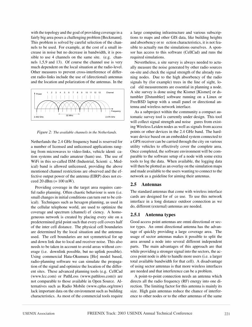
2.4 Radio PlanningIn the Netherlands there are 13 radio channels allowedin the 2.4 GHz frequency band to be used for radio localarea networks. Due to the DSS technology a used chan-nel does not occupy a single discrete frequency but is adistribution of power in a 22 MHz wide frequency inter-val. In Þgure 2 it is shown that there are 3 completelyseparate channels available. Combining this knowledge
FREENIX Track: 2003 USENIX Annual Technical ConferenceUSENIX Association 221
with the topology and the goal of providing coverage in afairly big area poses a challenging problem [Beckmann].This problem is solved by careful selection of the chan-nels to be used. For example, at the cost of a small in-crease in noise but no decrease in bandwidth, it is pos-sible to use 4 channels on the same site. (e.g. chan-nels 1,5,9 and 13). Of course the channel use is verymuch dependent on the local situation at the radio-level.Other measures to prevent cross-interference of differ-ent radio-links include the use of (directional) antennasand the location and polarization of the antennas. In the
1 2 3 4 5 7 8 96 10 11 12 13
2.402 GHz 2.476 GHz
Channel
Frequency
Power
22 MHz
Figure 2: The available channels in the Netherlands.
Netherlands the 2.4 GHz frequency band is reserved fora number of licensed and unlicensed applications rang-ing from microwaves to video-links, vehicle identiÞca-tion systems and radio amateur (ham) use. The use ofWiFi in this so-called ISM (Industrial, ScientiÞc, Med-ical) band is allowed unlicensed, providing the abovementioned channel restrictions are observed and the ef-fective output power of the antenna (EIRP) does not ex-ceed 20 dBm (= 100 mW).
Providing coverage in the target area requires care-ful radio planning. Often chaotic behaviour is seen (i.e.small changes in initial conditions can turn out to be crit-ical). Techniques such as hexagon planning, as used inthe cellular telephone world, are used to optimize thecoverage and spectrum (channel) efÞciency. A homo-geneous network is created by placing every site on apredetermined grid point such that every cell covers halfof the inter cell distance. The physical cell boundariesare determined by the local situation and the antennasused. The cell boundaries are not symmetrical for upand down link due to local and receiver noise. This alsoneeds to be taken in account to avoid areas without cov-erage (i.e. downlink possible, but no uplink possible).Using commercial Hata-Okumura [Ho] model based,radio-planning software we can simulate the propaga-tion of the signal and optimize the location of the differ-ent sites. These advanced planning tools (e.g. CellCad(www.lcc.com) or PathLoss (www.pathloss.com)) arenot comparable to those available in Open Source. Al-ternatives such as Radio Mobile (www.cplus.org/rmw)lack important data on the environment such as buildingcharacteristics. As most of the commercial tools require
a large computing infrastructure and various subscrip-tions to maps and other GIS data, like building heightsand absorbency or reßection characteristics, it is not fea-sible to actually run the simulations ourselves. A spon-sor has access to this software (CellCad) and runs therequired simulations.
Nevertheless, a site survey is always needed to actu-ally measure the noise generated by other radio sourceson-site and check the signal strength of the already run-ning nodes. Due to the high absorbency of the radiosignals by (for example) trees in the line of sight, lo-cal Þeld measurements are essential in planning a node.A site survey is done using the Kismet [Kismet] or ds-tumbler [Dstumbler] software running on a Linux orFreeBSD laptop with a small panel or directional an-tenna and wireless network interface.
As a subproject within the community a compact au-tomatic survey tool is currently under design. This toolwill collect signal strength and noise Þgures from exist-ing Wireless Leiden nodes as well as signals from accesspoints or other devices in the 2.4 GHz band. The hard-ware device based on an embedded system connected toa GPS receiver can be carried through the city on variousutility vehicles to effectively cover the complete area.Once completed, the software environment will be com-parable to the software setup of a node with some extratools to log the data. When available, the logging datawill then be plotted as an overlay on the simulation mapsand made available to the users wanting to connect to thenetwork as a guideline for aiming their antennas.
2.5 AntennasThe standard antennas that come with wireless interfacecards are designed for ofÞce use. To use this networkinterface in a long distance outdoor connection as wedo, different (external) antennas are needed.
2.5.1 Antenna typesGood access point antennas are omni directional or sec-tor types. An omni directional antenna has the advan-tage of quickly providing a large coverage area. Theusage of sector antennas makes it possible to split thearea around a node into several different independentparts. The main advantages of this approach are thatwhile providing a stronger signal into the sectors, the ac-cess point node is able to handle more users (i.e. a largertotal available bandwidth for that cell). A disadvantageof using sector antennas is that more wireless interfacesare needed and that interference can be a problem.
A point-to-point connection needs an antenna whichdirects all the radio frequency (RF) energy into one di-rection. The limiting factor for this antenna is mainly itssize. High gain antennas reduce the chance of interfer-ence to other nodes or to the other antennas of the same

FREENIX Track: 2003 USENIX Annual Technical Conference USENIX Association222
node but are often quite large in size.The key to a successful antenna setup for a given node
location is in evaluating the simulation results togetherwith the site survey details. After that, the cost factoris not to be neglected in the selection process. In somecases a home-made antenna can have a better price / per-formance ratio than a commercial one.
Clients need a directional antenna to connect to anode. There is no need for clients to be connected tomore than one node at the same time. The main speci-Þcation for the client antenna is the minimum gain thatis needed to obtain a signal strong enough to make agood connection to an access point. Based on this gain,several different types of antennas are available. Otherfactors that determine the best antenna are the physicalsize, appearance and the cost of the antenna.
Simple antennas for use with access points [Omni],clients [Quad] or point-to-point connections [Yagi] canbe made at home, keeping the price at the lowest possiblelevel. Almost anything can be turned into an antenna. Ithas been shown that it is not difÞcult to make a WiFiantenna [Pringle]. The Wireless Leiden website has alarge collection of antenna designs provided by users.
The layout of the Wireless Leiden network is designedon a typical client antenna gain of 7 dBi. Antennas withthis gain are cheap and / or easy to construct.
2.5.2 Lightning protectionLightning protection is only applied at the building level,like connection of the antenna pole to the existing light-ning protection system. This means that there are nospecial surge protectors used in the antenna cables. Thechance that lightning strikes in the Netherlands is sosmall compared to the cost of the arrestors and the prob-lems associated with them (like insertion loss and theprotection level they provide) that the risk of getting the(low cost) equipment damaged by lightning is accept-able.
2.6 IP space PlanningThe network uses TCP/IP as the transport layer. There-fore, every active element in the network should havean address. Using a private IP version 4 range, enoughaddresses will be available. Using IP version 6 will bea future enhancement and is not yet fully implemented.So, as the IP network grows there is a need for not onlyplanning the radio frequency space, but also planningthe IP space. The IP range is assigned on the basis ofthe different postal (zip) code regions in the coveragearea, combined with the population density and averageincome per head. Client machines are provided with thecorrect network information for the area they are in by alocal DHCP server running on the (Þrst) node (the accesspoint) they are connecting to. The information provided
by the DHCP server is the IP address to use, the netmask,the nameserver addresses and the default gateway.
Any two nodes in the backbone that are connected toone another by a point-to-point link use a /30 IP range(i.e. 4 IP addresses). This ensures that tracerouteshows the logical network topology (no physical hopsare missing because all packets must rise to the IP level,none are routed by MAC address). IP space that is usedfor numbering an interlink from node A to node B isassigned from a separate IP range; it should belong toneither geographical area A or B, as it is part of the back-bone.
2.6.1 Internal routingHaving the IP space mapped to the physical map, anumber of areas are created that contain different sub-networks. Between these areas there are different net-work links. This approach creates multiple routes froma source to a destination. It is no longer possible to man-ually manage the routing tables in all nodes that havemore than one interconnect. Using the Open ShortestPath First (OSPF) routing protocol minimizes the rout-ing conÞguration of a node. As soon as the appro-priate interlinks are made (or broken) on the IP level,the OSPF processes start to exchange information abouttheir knowledge of the network topology. This also al-lows us to add or remove nodes from the network with-out any routing reconÞguration.
Using the hop count and cost factors on variousroutes, the system will select the route with the lowesttotal cost. If any link fails, it is detected by the OSPFdaemons and all routing tables in the network will be up-dated to reßect the new situation. Currently, routing isdone solely on hop count. All cost factors are the same.
By using OSPF routing and different interconnects onone node, the reliability of the network on the IP level isgreatly enhanced at a negligible cost of processor over-head and network bandwidth.
For the implementation of the OSPF protocol the Ze-bra [Zebra, Routing] package is used. Zebra is an OpenSource package which provides a number of differentrouting protocols by various daemons, all controlled bya master daemon. Currently OSPFv2 routing is usedthroughout the backbone network because the protocolis Þt to the topology and does not impose a large over-head.
2.6.2 External routingUsing a private IP space on the network will introducenew issues on routing when connecting the network tothe Internet using multiple ISP connections. Some nodeshave an external default gateway that is injected intoOSPF. These routes are propagated through the networkso that each node has one or more routes to the Internet.

FREENIX Track: 2003 USENIX Annual Technical ConferenceUSENIX Association 223
Currently there is no smart algorithm to decide whichone to use (or to use a particular route to the Internet fora particular user). Several options are being investigated:tunnels (e.g. PPTP), source routing and the use of proxyservers.
Also, discussions with RIPE are planned to addressthe possibility of obtaining a block of IPv4 numbers to-gether with an AS number. This will ease some of theISP connection problems.
2.7 Site allocationOnce a site is designated by using the planning proce-dure, it might be a tedious task to get permission fromthe different building-owners to have the antennas andequipment installed. Because of the not-for-proÞt andvolunteer-driven nature of this project, it might be dif-Þcult to explain to the building owner that we are notable to pay the same amount of money as a cellularphone provider. A cellular provider will easily pay up toEuro 10,000 each month for a location. We, as WirelessLeiden afÞliated volunteers, have organized ourselves inan ofÞcial charitable trust (foundation) with a statute,and this foundation has managed to generate some pos-itive publicity. Being an ofÞcial foundation with somemedia exposure and a good story — a free, fast commu-nity network — has been helpful in gaining rooftop accessfree of charge. Having access to people knowledgeableon building and safety issues ensures a setup accordingto all local building regulations, like measures againstlightning strikes.
Locations that are important to the community, likeschools or the Town Hall, are target locations to set upnodes. Also cooperating commercial enterprises thatwant to provide services on the network or want to makeuse of the network for private communications (e.g. be-tween different branch ofÞces) are quite willing to investin the equipment and time to set up and maintain a node.
2.8 Setting up a NodeA typical network node setup consists of a number ofantennas and a computer system. We use 2 or more di-rectional antennas to connect to other backbone nodesand one omni-directional antenna for local client access(See Þgure 3). A PC or other system provides the routingand access-point functionality. A typical node setup canbe found in Þgure 4. The home-built and partly commer-cial antennas are connected to a computing platform thatcan, but does not need to be connected to the local net-work at the site using wired Ethernet. Setting up a net-work node requires some real hard hardware work to getthe antennas lined up and afÞxed to the building. As weare using directional and polarized antennas to preventinterference, the alignment of the antennas is fairly criti-cal. Once the antennas are set up, connection to the node
Figure 3: Antennas as mounted on a building (2 directionalantennas and one omnidirectional antenna).
machine is done using low loss coaxial cable. As keep-ing cable losses to a minimum is important, the length ofthe cable should be minimized as each meter of antennacable introduces a loss of approximately 0.25 dB. Thenode machine should be as close as possible to the an-tennas. When using a small embedded system (see sec-tion 2.9) the node computer can even be mounted outsideon the antenna pole. In this case, special measures haveto be taken to weatherproof the setup (e.g. like prevent-ing condensation). This setup can use Power over Eth-ernet (PoE) [PowerF] [PowerS]. A single UTP networkcable (where the length is not an issue provided that itis less than 100 meters) connects the antenna setup tothe power supply (indoors) and the on-site local wiredEthernet if needed.
Before and after the installation of the node hardwarea number of basic alignment, throughput, and reliabil-ity tests have to be run. These tests are used to be surethat the links in the set-up will operate as expected. Theexpectation values for these tests are derived from thesite survey and simulation results as described in sec-tion 2.4. The alignment test comprises of monitoring thesignal strength and noise Þgure when a backbone link isestablished. By physically varying the antenna directionthe signal as seen by the driver software on the wire-less interface should be maximized, while the reportednoise is minimized. Throughput and reliability is testedby transferring large chunks of data from one node to itsneighbor and observing the packet loss and transfer rate.
Often, once the node is set up it is quite difÞcult tophysically access the machine and the antennas becausethey mostly are located at remote locations and in build-ings with complex access procedures. A typical test forthe reliability is to copy some video data (often com-prised of large Þles) through the node. This test differsfrom the test mentioned above where a single wirelesslink is tested, here the complete (routing) functionality

FREENIX Track: 2003 USENIX Annual Technical Conference USENIX Association224
of a node is tested. A test protocol is used to assure therepeatability of the test procedures.
An external hardware watchdog device is used to en-sure a reboot of the system when some part of the soft-ware crashes. These watchdog devices are home builtand very simple. The watchdog watches the serial portof the node computer for a ÒhelloÓ string. This string hasto be sent every minute (using a small program or evena script). If this string is not received within 90 secondsof the previous string, the watchdog circuit will cut thepower to the setup and will turn it on after a minute. Us-ing either journaling Þle systems or RAM based Þle sys-tems minimizes problems caused by a fsck operationafter the setup has been powercycled.
Directional Antennas
WatchdogMains
To Neighbour Nodes
WirelessLeiden Node
PCIWiFiboards
Local Ethernet network
OnmidirectionalAntenna
To ClientsOutdoor
Indoor
Linux or *BSD machine
Figure 4: A typical WirelessLeiden Node setup.
The software environment on the machines is a stan-dard Open Source free UNIX (currently FreeBSD) dis-tribution stripped down to Þt in a minimal hardware con-Þguration. The (kernel) device drivers that are used tocontrol the wireless network cards and some networkoperations and management utilities are added (ref. sec-tion 2.10).
Using a standard off-the-shelf Open Source operat-ing system enables us to implement a node quite fastwhile at the same time keeping the ßexibility of chang-ing things on all levels when the network grows and /or the technology changes. Another aspect is the largeand diverse knowledge-base available within the devel-opment and engineering group. Also, the Open Sourcedevelopment model guarantees a fast turn around timein Þxing bugs or evaluating features. Last but not least,in a not-for-proÞt organization working from donationsthe initial cost of the software is of major importance.
2.9 Hardware PlatformEach node needs a piece of hardware that handles thewireless signal and provides IP routing. Currently Intel
Pentium I class PC machines with a PCI bus are used.The wireless interface cards are standard cards using theIntersil PRISM series chip set and a PCI bus, such asthe Linksys WMP11 or Compaq WL200. The PCs usedare often found as surplus machines or are donated. Dueto the different hardware conÞgurations of the machinesit is difÞcult to standardize the hardware and improvethe reliability. To overcome these problems different op-tions are evaluated. Commercial wireless nodes (e.g. theNokia rooftop systems) are not an option as they are of-ten not ÒopenÓ and far too expensive. Often they useproprietary adaptations from the 802.11 standard and arenot accessible to the developers in the community to de-velop the hard- and software further.
Embedded systems based on i486 or better processorswith at least one Ethernet interface and at least 2 slots forconnecting wireless network cards are a good alterna-tive. When using an Intel i486 or better processor mostof all software developments can be reused.
Embedded boards are available in various differentßavors. At this moment we are testing the Soekris En-gineering embedded boards. These boards use an i486compatible processor (AMD Elan SC 520) running at133 MHz, 64 Mbytes of RAM, a Compact Flash slot, amini PCI slot and two PCMCIA slots. Figure 5 shows ablock diagram of this board when used as wireless net-work node. For the PCMCIA and Mini PCI solutionwireless cards based on the PRISM 2 reference design(e.g. SENAO) are used. This adds software compatibil-ity with the PRISM 2.5 based PCI cards that are usedin the PC design. The Soekris board is a commercialproduct and will run either Linux or a ßavor of BSDwithout problems, freeing the developments in the nodesoftware from the hardware developments. Other indus-trial Intel based boards often use various bus standards(e.g. PC 104), which add additional costs in connecting(standard) cards for wireless networking. Self-designinga board level solution is not an option due to lack of re-sources and money. At a price higher than the price ofthe donated PC machines these embedded systems willadd reliability and standardization to the node base. Theintention is to migrate the core network nodes from PCÕsto embedded systems.
2.10 Software PlatformThe main choice of Operating system for a Wireless Lei-den Node is FreeBSD. In the development of the Wire-less Leiden node a number of problems were encoun-tered which have resulted in the current FreeBSD instal-lation.
Initial Linux implementations of the node functional-ity resulted in problems with the performance and sta-bility of the systems. Partly they were due to the olderhardware used: the PCI controller not allowing to assign

FREENIX Track: 2003 USENIX Annual Technical ConferenceUSENIX Association 225
WirelessPCMCIA
WirelessPCMCIA
Power
Compact Flash
MiniPCI Wireless64 Mbytes
Antennas
486
(9..48V)
RAM
NET 4521Soekris.com
Ethernet (2)
Serial
Figure 5: A Soekris based node.
different interrupts to the wireless cards and the inter-rupt handling in the Linux kernel. Other problems wereconnected with using multiple wireless cards with thePRISM hostap driver [HostAP]. We could have usedother drivers (e.g. wlan-ng), but the hostap driver wasthe only one implementing an user software (i.e. notÞrmware) driven access point functionality. Anothermajor issue was the number of different Linux distribu-tions around and the rapid change thereof.
Using FreeBSD solved some of the Linux-relatedproblems, like interrupt handling on heavily loaded sys-tems, while adding features such as having one buildtree, a steady release and distribution scheme. Further-more, a single stable PRISM 2 support stack and accessto a more mature conÞguration system makes the systemmore suitable for mass deployment. Another beneÞt ofusing FreeBSD is the inclusion of several wireless net-work card Þrmware cutoff checks which will restrict thefunctionality accessible from userland when a too oldversion of the Þrmware is detected.
For the Compaq WL200 card we did have to Þx aspeciÞc routing bug which was introduced in betweenFreeBSD 4.6 and 4.7 as part of the cardbus / newbusproject. This has since been picked up by CURRENTand will be in the next release of FreeBSD. Prior toFreeBSD 5.0 release some issues where also found andreported with regard to the wicontrol and ifcon-fig settings not being propagated properly. These havesince been Þxed.
It should be noted that each of the different wirelessstacks on Linux has at least one or two elements whichare vastly superior to the rather dated PRISM 2 supportin FreeBSD; but unfortunately each stack also exhib-ited showstoppers ranging from erroneous detection ofcards to kernel panics. It is not unlikely that a maturingor crystallizing, of one of the wireless options of Linuxwill make Linux a viable choice in the near future. This,
combined for example with a good AODV routing pro-tocol implementation (see section 3.4), may again causeus to switch platforms. Another, unplanned, beneÞt ofthe BSD stack is the rather mature diskless boot systemwhich is part of the standard distribution; which is anexcellent starting point for automated installers and sys-tems operating from a read-only storage device.
As FreeBSD has just a single version number and re-lease path; the entire ÕbuildÕ procedure of the master ma-chine from which all nodes are automatically built en-tails less than 5 kbytes of script; just short of one page.The ÕdeÞnitionÕ of a node, including kernel conÞgura-tion, routing, antenna frequencies etc.; i.e. all that needsto be deÞned given a speciÞc version of FreeBSD, cur-rently runs at around 12 kbytes of data.
Tools such as ÕmergemasterÕ available in FreeBSDand the rather elaborate documentation make upgradesin the Þeld, even across versions, reliable and pre-dictable. Likewise extensive use is made of the ÕportsÕcollection to manage the versioning and updating ofÒthird partyÓ packages such as the ISC-Bind, Zebra anda few others.
2.11 Version controlDeploying a large number of network nodes consistentlyand reliably, depends for a large part on the version con-trol of the different conÞgurations and their conÞgura-tion Þles. In the Wireless Leiden project Subversion isused together with a system called Genesis.
Subversion [svn] is a new breed of CTM; akin toSCCS or CVS - but more suited to Open Source codemanagement as it does not require extensive Unix ac-count management and can be conÞgured to use HTTPas its communication protocol. Currently, Subversion ishosted on a remote machine and is connected to the In-ternet through a DAV module and an Apache 2.0 webserver. Access controls are intentionally light and com-mit access is virtually for the asking. Genesis is a webbased homebuilt conÞguration Þle generator written inPERL [Perl5].
Due to the remote installation of both the Subversionand Genesis installation and conÞguration of a Node ma-chine relies on a live Internet connection. However, itshould be noted that both systems could be moved toa more ÕlocalÕ environment close by or could be repli-cated. So far this has not been necessary.
2.12 Building the NodesApart from doing the real hard hardware setup of a node,the software conÞguration on the system has to be set up.To automate the software installation and conÞguration,the Wireless Leiden Node Factory was developed. A nontrivial solution was needed because node conÞgurationsdiffer more than just by their IP address, due to different

FREENIX Track: 2003 USENIX Annual Technical Conference USENIX Association226
hardware conÞgurations and platforms being used.
2.12.1 The Node Factory setupThe node factory consists of a central machine whichcontains the distribution(s) to be installed on the nodealong with a diskless boot environment. The latter isused during the initial boot as a staging ground for theactual install. A new machine is connected to the centralmachine, booted from ßoppy using ÕetherbootÕ whichsubsequently launches into a diskless FreeBSD install.All hardware will be detected, a reformat of the harddisk is done and the node software is installed and con-Þgured.
The install master server is a machine with two net-work cards and a single wireless network card. Atpresent a Pentium II class machine with 256 Mb mem-ory and 4 Gb harddisk is used.
The Þrst network card connects to the Internet througha DSL connection. This is needed to fetch source, bina-ries and conÞguration Þles. The second network card isconnected to the machine to be installed and conÞgured.The wireless network card is used for the automated testsduring the installation.
As the Þrst network interface on the server providesInternet connectivity, the second nic offers a NFS, anetherboot and a PXEboot environment to the client to beinstalled. To enable NFS standard FreeBSD rc.conf andexport settings are used; etherboot ßoppies are createdusing the default version in /usr/ports and the PXEbootenvironment relies on the DHCP daemon using a stan-dard conÞguration from the handbook.
In order to allow a newly installed node to access theInternet routing is enabled between the nics by a gate-way enable setting in rc.conf.
The software is retrieved from the Net by down-loading a FreeBSD image. After installing this on theserver software was upgraded from 4.7 to the CUR-RENT branch of FreeBSD and frozen. The CURRENTbranch was selected over the STABLE branch at thattime to make sure the latest wireless drivers and patchesthereof were included. However, testing on basic func-tionality was needed to validate the distribution for pro-duction use.
Using the make world mechanism with a differentDESTDIR, a complete separate FreeBSD tree is built.Added to this tree at the root is a special diskless in-stall kernel and, in the default /boot/kernel location, astripped down run time kernel. Furthermore, two addi-tional scripts are added in the root which will controlthe actual install. An extra rc.local script is added whichwill run as the Þnal step during the Þrst diskless boot.The latter causes the disk to be partitioned, formattedand the install to start.
The next step is making a bootßoppy for each of the
network cards with the right version of etherboot. OnSoekris embedded systems the native PXE boot environ-ment is used instead.
2.12.2 Building a Node system
Preparation for building a new nodes means collecting aPentium (or better) CPU some RAM, two or three wire-less lan cards and an Ethernet card. A 500 Mb harddisk(or more) will do Þne. The BIOS of the PC is conÞguredto boot from ßoppy disk, or in the case of the Soekris, toboot from the network using PXE. Besides the BIOS onthe Soekris machines, we have not tried any BIOS-es orEthernet cards which supported PXE directly but haverelied on a few different etherboot ßoppies instead.
In the Þrst stage the new machine boots from ßoppydisk to initiate etherboot. DHCP will assign an IP ad-dress and provide the parameters which allow the nodeto mount the NFS Þle system. After loading the kernel,a script prepares the harddisk by making it bootable, de-Þnes its partitions and formats Þle systems. This is fol-lowed by copying all the Þles from the server to its ownharddisk. After a reboot the new machine has it ownsystem in order to run.
After the reboot installation of some packages such asa dhcp-server, a nameserver, snmp etc. takes place. Theinstallation is managed by a set of homebuilt scripts (seesection 7). The reason to do so after a reboot rather thanduring the diskless boot is that during the initial disk-less boot we do not want to rely on having sufÞcientmemory available. The diskless system uses a mem-ory based /var and /tmp overlay and therefore consumesquite some memory. The scripts are invoked by a stateengine at the end of the boot procedure.
At the end of the procedure the new machine willshow a list of hostnames. After entering one at the com-mand line the machine will lookup its conÞguration onthe Internet in the remote Genesis. The old Þles will bebacked up and the new ones that deÞne the speciÞc nodewill be put in the right places.
Then approximately 15 minutes after the Þrst (ßoppy)boot, the new machine is in operational state and readyto be deployed and located at site.
2.13 Design rationale
Using this Node Factory setup for building a networknode it is very easy to setup and deploy wireless nodes,while ensuring a maximum of maintainability. The low-level conÞguration of each node is nearly identical andby using version control and the conÞguration databaseit is very easy to track down changes and keep thesedocumented. A last important point is that using OpenSource software the complete system will end up to bevery cheap.

FREENIX Track: 2003 USENIX Annual Technical ConferenceUSENIX Association 227
2.14 SecuritySecurity is currently not applied on the network infras-tructure level. Of course, all network nodes have ap-propriate security to secure the boxes themselves, butas an infrastructure provider, we have the rule of Óse-curity is the responsibility of the userÓ. On the ra-dio level we use a combination of narrow beams (di-rectional antennas) to interconnect nodes together withWired Equivalent Privacy (WEP) or even a WEP infras-tructure with dynamic keying. As WEP provides noactual security [Borisov], the user of the infrastructuremust be aware of the insecurity of the transported data,and use security on a higher level, for example by usingIPsec tunnels over the existing infrastructure. Raisingawareness of these problems and their solutions by theusers is important. Right now the projects website ad-dresses this in detail.
The nature of the transport layer adds an extra possi-bility of Denial of Service (DoS) attacks by ÒjammingÓa connection on the radio level. This can happen whenanother device using the same frequency is operatingin close vicinity of the node. Because we are operat-ing concurrently with other users in the same frequencyspace this can be a problem. Adding redundant paths to-gether with the appropriate routing protocols is the wayto overcome the problem for the user.
2.15 Running a Network NodeThe network node is highly self-contained and does notneed frequent maintenance visits. All software and con-Þguration maintenance, upgrading etc. is done from thenetwork itself using the conÞgurations in the repository.Software level reconÞguring of the node can be done onthe ßy to cope with the changing network architecture.
However, some on-site hardware maintenance maybe needed. Typical issues to be considered are takingcare of the fans in the power supply and coping withhardware failures such as hard disk problems. Further-more, some hardware maintenance on the antennas isneeded. Regular inspections of the state of the antennasand mounting hardware are required to ensure safe andreliable operation. Local building safety regulations mayalso require regular on-site inspections of the set-up.
The Network node can be connected to the usersÕ(home) network in order to give the local user wiredaccess to it. Therefore, on the Ethernet port DHCP isenabled.
TrafÞc and other operational data on the node is gath-ered using RRDB and RRDtool [RRDB] and sent to thecentral repository at regular intervals. Some examplesof graphs used can be found in Þgure 6. For simpleÒhealthÓ management of the nodes the free version ofBig Brother [BB] is used. Big Brother generates a num-ber of Òstatus lampsÓ on the network map available on
Figure 6: A link traffic and ping latency graph made byRRDtool.
the website. The combination of the graphs created byRRDtool together with the ok-notok information fromBig Brother has shown to be a valuable tool to monitorthe network. If the network and its trafÞc grows, othertools may be needed.
3 ResultsWithin approximately 1.5 years the network has grownform a single point-to-point connection to a completelyusable network. Logging MAC address data shows thatthe network is used by approximately 300 different ma-chines. On a day-to-day basis it is currently estimatedthat approximately 100 users are connected. With the in-troduction of (free, sponsored) Internet connectivity onthe network this will without doubt grow. Although thelearning curve was steep, the fully operational networkis now gaining more acceptance as more applications be-come available.
3.1 ApplicationsDuring the Þrst year of this project we have succeededin building about 12 network nodes in the Leiden area.These nodes are interlinked with their neighbors by802.11b links and have access points to accommodateusers to connect wireless to the network. Applicationscurrently in use are various VPN connections of enter-prises giving their employees access to the company net-work, schools with different locations connected to eachother, a video server and some gaming applications.
As of March 2003 a large Internet provider is spon-soring the Wireless Leiden Foundation with a number ofhigh speed (8 Mbit/s) DSL connections. Without rais-ing big routing and peering problems the Þrst phase ofintegrating Internet connectivity to the Wireless Leidennetwork a number of proxy servers [Squid] and captive

FREENIX Track: 2003 USENIX Annual Technical Conference USENIX Association228
portals [NoCat] are being deployed to allow the clients tosurf the Internet using http and https only. In the mean-time, a more deÞnitive network design that allows mul-tiple ISPs to use the infrastructure is being developed.
Due to the achieved outdoor coverage of the network,applications that require mobile use of the network arepossible. These applications are currently being devel-oped by users of the network. We are investigating howthese applications will use the network and what addi-tional features they might need (e.g. roaming function-ality and / or the use of MobileIP [MobileIP]).
3.2 ProblemsProblems that are encountered during the start-up phaseof the network can be divided into two groups. There aretechnical and non-technical problems to be solved.
Technical problems are seen on every level of the net-work stack. Starting with the physical level, it is difÞ-cult to plan the network using the different constraintslike noise, limited channels available, natural and otherobstacles. Due to this issue the conÞguration of the net-work is constantly evolving. Changing of antenna direc-tions can be difÞcult once a node is set up.
On the higher levels we have encountered problemswith the network drivers for the wireless boards we areusing. These problems can seriously affect the through-put and reliability of the network. Here the use of opensource software and the open source development modelpays off. Problems can be solved within the group, orwith help and information gained from the Internet. Alsohaving a choice between different solutions to the prob-lem helps.
On the IP level, having many point-to-point links anda number of applications results in quite a big puzzleto get everything conÞgured correctly. Using a centralconÞguration repository and the use of routing protocolshelps, but some problems still remain to be solved. Forexample when connecting to the Internet (with a num-ber of providers), routing and numbering issues needs tobe solved. Also the latency in the network might pose aproblem in some near real-time applications or applica-tions that use streaming technology (e.g. live video).
Furthermore, the reliability of the hardware can be aproblem. Because of cost issues, complete (used) PCmachines are in use as network nodes. These machinesare not as reliable as dedicated routers running on em-bedded systems without moving parts (like fans or hard-disks). Minimizing the points of failure, testing, validat-ing and proper maintenance helps a lot here. Ultimately,using embedded systems will ease this problem.
Non-technical problems include gaining acceptancewithin the town and the community. Without a broadacceptance and support of various organizations it is notpossible to build this kind of a network in a not-for-proÞt
fashion. Access to rooftops of high buildings etc. is es-sential. However, we do not believe that a for-proÞt or-ganization has any chance of succeeding at all. The up-front costs of building a network without volunteers arevery large. Possible revenue streams will be insufÞcientto recoup those large costs.
The other difÞcult task is to manage a large group ofvolunteers that are actually doing the work. With thegrowth of the network, also new people are joining to dothe design, management and the building of the networkand the nodes. With every new engineer another degreeof (intellectual) freedom is added to the system. Man-aging this enormously large and diverse task force in anopen manner can be difÞcult.
Also, we see that on the non-technical level the morereligious ideas between e.g. the different operating sys-tems or engineering solutions on a speciÞc topic are aproblema to cope with (like *BSD vs. Linux). Hav-ing a heterogeneous set-up with different operating sys-tems will gain a broader acceptance within the group andprobably builds a more robust network, but will be muchmore difÞcult to manage.
3.3 ExperiencesRight now, the network is in full operation and the Þrstapplications are successfully being deployed. Due to therather small group of technically skilled people the mainfocus of Wireless Leiden has been to set up nodes andprovide coverage in the historical center of Leiden. Inaddition we have concentrated on knowledgeable indi-viduals and professional organizations as Þrst users, be-cause they require less IT-assistance from the volunteers.As this is accomplished, the next step is extending thenetwork to the suburbs and connecting the actual privateusers to the network.
Doing research in this environment is very attractive:the big advantage is that a testbed (i.e. an actual runningnetwork) is already deployed, so actual Þeld testing ofnew technologies is relatively easy.
3.4 Future workFor the coming year a target is set to build and install atleast one new network node every month to extend thecoverage and increase reliability and bandwidth. Thesecond target is to set up a structure to effectively helpthe individual users to connect to the network. A thirdtarget is getting more applications running.
New technologies are being tested to cope with the ex-pected growth of the network. Upgrading the backbonelinks between network nodes to use 802.11a or 802.11gtechnology (max. 54 Mbit/s) [WCompare, IEEE] is intest.
Also in evaluation is the use of more complex andadvanced technologies using mesh or ad-hoc network-

FREENIX Track: 2003 USENIX Annual Technical ConferenceUSENIX Association 229
ing [Hu, Maltz, Royer]. Imagine a network where allclients are also a node and every client is connected tothe two or three closest other clients (close is deÞnedhere as the distance at which one is able to create a good(signal to noise ratio) connection at that particular mo-ment in time), not to a central node in the neighborhood.The noise ßoor would remain at the same level as thenetwork gets more dense while the number of possibleparallel paths from A to B also grows with the number ofclients. More clients lead to shorter paths which will re-sult in less RF power needed to obtain the same connec-tion quality. Each new participant brings along his or herown piece of network, bandwidth and noise-reduction.
Using these techniques, advanced routing architec-tures auch as AODV may be used. The Ad hocOn Demand Distance Vector (AODV) routing proto-col [AODV, aodv-ietf] is an Òon demandÓ routing al-gorithm, only creating routes when they are actuallyneeded. AODV is loop-free and scales to large numbersof mobile nodes.
Another point of evaluation is the use of applicationsthat require Quality of Service (QoS) facilities in the net-work such as IP telephony and wide band video stream-ing.
4 Related work
In different parts of the world wireless communities aredeveloping. In the USA there are a number of leadinginitiatives [nyc, Seattlewireless, FreeNetworks], but alsoin Europe and Australia communities have been formed.The main difference between the Wireless Leiden net-work and a number of other wireless communities is thatWireless Leiden deÞnitely not has a hobby-network kindof style and set-up. Due to the professionals afÞliatedwith the Wireless Leiden Foundation and the partner-ships with major (local) groups of potential users, hard-ware vendors, the university and content providers it isfar beyond the concept of a number of people sharingtheir DSL connection using wireless technologies. Theother main difference is that due to the acceptance by thecommunity and therefore the possibility to set up nodeson a large number of non-individually owned buildings,all connections between the network nodes can be wire-less. No wired connection is needed. Here the European(or Dutch) mentality of cooperation to achieve the bestresult may be an advantage.
Last but not least, as the infrastructure is based onopen standards and Open Source software, it is freeingus from vendor lock-ins and is achieving the broadestpossible range of applications while providing sustain-ability of the complete system.
5 ConclusionWith the use of relatively low cost technologies andOpen Source software it is possible to build a wirelessnetwork which is used by the community. Technicalproblems do exist, but by usage of Open Source soft-ware they can easily be solved. The process of buildinga network using a loosely-coupled group of volunteersis not easy but bringing organization in the group whenthe network becomes more complex helps a lot. Havingthe back-up of the community and local enterprises alsohelps to gain momentum and visibility of the project,which in return speeds up the development and growthof the network.
6 AcknowledgmentsThe authors wish to thank all people afÞliated with theWireless Leiden foundation, The city of Leiden and thesponsors of the project. Without the dedication, pro-fessionalism and enthousiasm of these people and or-ganizations this project would not be able to prove itssuccessfulness. Special thanks go to the following peo-ple: Johan de Stigter of Gandalf and Evert Verduinof WirelessDesign for their technical input. Further-more thanks go to Caroline Beijer, Brad Knowles andDick van Velzen for their valuable comments. Specialthanks also to the FreeNIX reviewers and to our shep-herd, Guido van Rooij.
7 AvailabilityAs the Wireless Leiden Foundation is an open commu-nity, all information, software and hardware that is beingdeveloped is free to use for everyone under the Gnu Pub-lic License. A WiKi website is available to effectivelyshare this information. Unfortunately it is in Dutch, butas engineering language is international, with some ef-fort the important technical info can be extracted. Thewebsite can be found at:
http://www.WirelessLeiden.nl
Direct links to the node software can be foundhere: http://www.WirelessLeiden.nl/wcl/cgi-bin/moin.cgi/InstallLayersThe subversion tree is available under the followinglink: http://wleiden.webweaving.org:8080/svn/node-config/master/
References[AODV] AODV: a routing protocol for ad hoc net-
works,http://w3.antd.nist.gov/wctg/aodv_kernel/
[aodv-ietf] Ad hoc On-Demand Distance Vector(AODV) Routing draft-ietf,

FREENIX Track: 2003 USENIX Annual Technical Conference USENIX Association230
http://http://www.ietf.org/internet-drafts/draft-ietf-manet-aodv-13.txt
[BB] Big Brother: a network monitor,http://www.bb4.com/
[Bawug] BaWUG, The Bay Area Wireless Users group,http://www.bawug.org
[Beckmann] D. Beckmann, U. Killat, Applied Fre-quency Planning for Cellular Radio Networks., Int.Journal of Electronics and Communications, 54-42000 pg. 211-217, 2000.
[Borisov] Nikita Borisov, Ian Goldberg and David Wag-ner, Intercepting Mobile Communications: The In-security of 802.11., 7th Annual International Con-ference on Mobile Computing and Networking,2001.
[Dstumbler] dstumbler: a wardriving / netstumbling /lanjacking utility for bsd operating systems,http://www.dachb0den.com/projects/dstumbler.html
[FreeNetworks] Free Networks, information on differ-ent community networks,http://www.freenetworks.org/
[HostAP] Host AP driver for Intersil Prism2/2.5/3,http://hostap.epitest.fi/
[Hu] Y. Hu, A.Perrig, D.B.Johnson, Ariadne, a SecureOn-Demand Routing Protocol for Ad-Hoc Net-works., MobiCom 2002,(2002).
[Ho] Hata-Okumura Model,http://wcrg.engr.ucf.edu/Web_Paper/HATA.html
[IEEE] IEEE working group for wireless LANs,http://grouper.ieee.org/groups/802/11/
[Kismet] Kismet sniffer,http://www.kismetwireless.net/
[Maltz] David A. Maltz, Josh Broch, and David B.Johnson, Experiences Designing and Building aMulti-Hop Wireless Ad Hoc Network Testbed., MUSchool of Computer Science Technical ReportCMU-CS-99-116. March 1999.
[MobileIP] IP Routing for Wireless/Mobile Hosts(mobileip),http://www.ietf.org/html.charters/mobileip-charter.html
[NoCat] The NoCat Community Wireless NetworkProject white paper,http://nocat.net/nocatrfc.txt
[nyc] New York City Wireless,http://nycwireless.net/
[Omni] Trevor Marshall, 802.11b WLAN WaveguideAntennas,http://trevormarshall.com/waveguides.htm
[Perl5] Perl5 Programmers reference,http://www.metronet.com/perlinfo/doc, (1996).
[PowerF] Power over Ethernet FAQ,http://www.nycwireless.net/poe/
[PowerS] Power over Ethernet standard working grouphttp://grouper.ieee.org/groups/802/3/af/
[Pringle] Rob Flickenger, Antenna on the Cheap(er, Chip), OÕReilly weblogs, Jul 5 2001.http://www.oreillynet.com/cs/weblog/view/wlg/448
[Quad] The Dutch double Quad antenna,http://sharon.esrac.ele.tue.nl/pub/antenne/13-double-quad.jpg
[Routing] R.Malhotra, IP Routing, OÕReilly & Asso-ciates, Inc. (2002).
[Royer] E. Royer and C.K. Toh, A review of currentrouting protocols for ad-hoc mobile wireless net-works., IEEE Personal Communications Maga-zine, pp 46-55 (1999).
[RRDB] Tobi Oetiker, RRDB and RRDtool,http://people.ee.ethz.ch/˜oetiker/webtools/rrdtool/
[Seattlewireless] Seattlewireless, a wireless communityin Seattle,http://www.seattlewireless.net
[svn] Subversion,http://www.tigris.org/
[Squid] Squid Web Proxy Cache,http://www.squid-cache.org/
[WirelessComm] Rob Flickenger, Building WirelessCommunity Networks, OÕReilly & Associates, Inc.(2001).
[WCompare] Netgear Wireless Comparison Whitepa-per, http://www.netgear.com/pdf_docs/WirelessInforev4.pdf
[WirelessNet] M. Gast, 802.11 Wireless Networks,OÕReilly & Associates, Inc. (2002).
[Yagi] SeattleWireless, Building Yagi antennas,http://seattlewireless.net/index.cgi/BuildingYagiAntennas
[Zebra] The ZEBRA routing package,http://www.zebra.org/