proceedings of asia-pacific microwave conference 2007 ...jbornema/conferences/114-07apmc-mba.pdf ·...
TRANSCRIPT
Advanced Stepped-Impedance Dual-Band Filters With Wide Second Stopbands
Marjan Mokhtaari 1, K. Rambabu 2, Jens Bornemann 1, Smain Amari 3
1 Department of Electrical and Computer Engineering, University of Victoria, Victoria, BC, Canada V8W 3P6 2 Department of Electrical and Computer Engineering, University of Alberta, Edmonton, AB, Canada T6G 2V4
3 Department of Electrical and Computer Engineering, Royal Military College of Canada, Kingston, ON, Canada K7K 7B4
Abstract—Advanced dual-band stepped-impedance resonator filters are prototyped and their performances verified. The main advantages compared to traditional designs consist in two controllable passbands at desired frequencies, which is achieved by utilizing all-electric coupling, wide stopband regions towards higher frequencies and relatively small circuitry. Measurements over a wide frequency range verify the suitability of the resonator arrangements for advanced dual-band filter applications.
Filter design; stepped-impedance resonators; dual-band filters; microstrip filters.
I. INTRODUCTION Recent advances in planar filter design have consistently
relied on the harmonic tuning properties of stepped impedance resonators [1]. Especially the second resonance of such resonators can be efficiently used either to create single passband filters with wide spurious-free stopbands, e.g. [2] – [6], or to design dual-band filters, e.g. [7] – [14]. In triple-resonance operation, stepped impedance resonators are employed in triple-band filters [15], [16] or ultra-wideband (UWB) filters, e.g. [17] – [19].
Common to almost all dual-band designs is a rather moderate stopband characteristic towards higher frequencies. This is mainly caused by the fact that in certain coupling schemes, the coupling in the second pass-band cannot be controlled efficiently, or that harmonic pass-bands cannot be suppressed.
Therefore, dual-band stepped-impedance resonator filters with new coupling schemes, which support fully controllable passbands in addition to wide stopbands towards higher frequencies, have been presented in [13]. These configurations are free of input and output matching networks and use stronger folding in order to reduce size. Moreover, they utilize electric coupling (end coupling) for both the first and the second passband, which allows the designer to control both passbands simultaneously.
This paper focuses on the theory-measurement comparison of advanced stepped-impedance resonator filters. It is demonstrated that these filters provide a wide second stopband towards higher frequencies as well as good passband separation and selectivity through the creation of transmission zeros.
II. DESIGN The typical half-wavelength stepped impedance resonator is
depicted in Fig. 1 with Z1 and Z2 being the characteristic impedances of the transmission line sections of electrical lengths θ1 and θ2, respectively. Following standard transmission-line theory, the resonance conditions for the fundamental and harmonic resonances are found as
( )2 12
1tan tan
2ZZ
θ θ⎛ ⎞= ⎜ ⎟⎝ ⎠
(1)
and ( )2 12
1tan tan
2ZZ
θ θ⎛ ⎞ = −⎜ ⎟⎝ ⎠
, (2)
respectively.
Figure 1. Half-wavelength stepped-impedance resonator.
Thus any desired frequency ratio of harmonic (f2) to fundamental (f1) resonances depends on the proper choice of the impedance ratio. An initial value for solving (1) and (2) assumes θ1=2θ2 and defines the impedance ratio of the stepped impedance resonator through [9]
21
1 2 12 tan ( )ff Z Z
π−= . (3)
Other initial values can be found in [20].
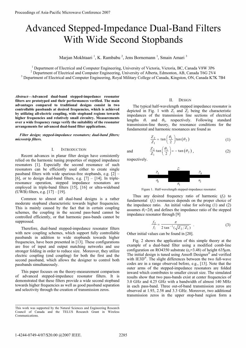
Fig. 2 shows the application of this simple theory at the example of a dual-band filter using a modified comb-line configuration on RO4350 substrate (εr=3.48) of height 635µm. The initial design is tuned using Ansoft Designer® and verified with IE3D®. The slight differences between the two full-wave codes are in a range observed before, e.g., [13]. Note that the outer arms of the stepped-impedance resonators are folded inward which contributes to smaller circuit size. The simulated results show that two pass-bands exist at center frequencies of 3.0 GHz and 4.25 GHz with a bandwidth of almost 140 MHz in each pass-band. Three out-of-band transmission zeros are observed at 1.93, 2.58 and 3.3 GHz. Moreover, two additional transmission zeros in the upper stop-band region form a
This work was supported by the Natural Sciences and Engineering ResearchCouncil of Canada and the TELUS Research Grant in Wireless Communications.
Proceedings of Asia-Pacific Microwave Conference 2007
1-4244-0749-4/07/$20.00 @2007 IEEE. 2285
complex zero pair at around 4.80 GHz. This offers the potential for further out-of-band suppression as demonstrated in the next section.
Figure 2. Response of a modified dual-band comb-line configuration on RO4350 substrate.
III. RESULTS The prototypes of the following filter structures have been
fabricated on RT5880 using a substrate height of 508µm.
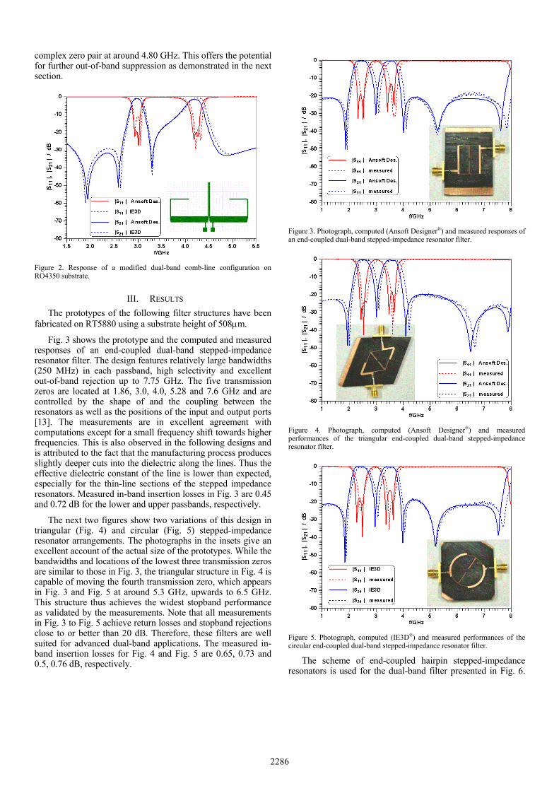
Fig. 3 shows the prototype and the computed and measured responses of an end-coupled dual-band stepped-impedance resonator filter. The design features relatively large bandwidths (250 MHz) in each passband, high selectivity and excellent out-of-band rejection up to 7.75 GHz. The five transmission zeros are located at 1.86, 3.0, 4.0, 5.28 and 7.6 GHz and are controlled by the shape of and the coupling between the resonators as well as the positions of the input and output ports [13]. The measurements are in excellent agreement with computations except for a small frequency shift towards higher frequencies. This is also observed in the following designs and is attributed to the fact that the manufacturing process produces slightly deeper cuts into the dielectric along the lines. Thus the effective dielectric constant of the line is lower than expected, especially for the thin-line sections of the stepped impedance resonators. Measured in-band insertion losses in Fig. 3 are 0.45 and 0.72 dB for the lower and upper passbands, respectively.
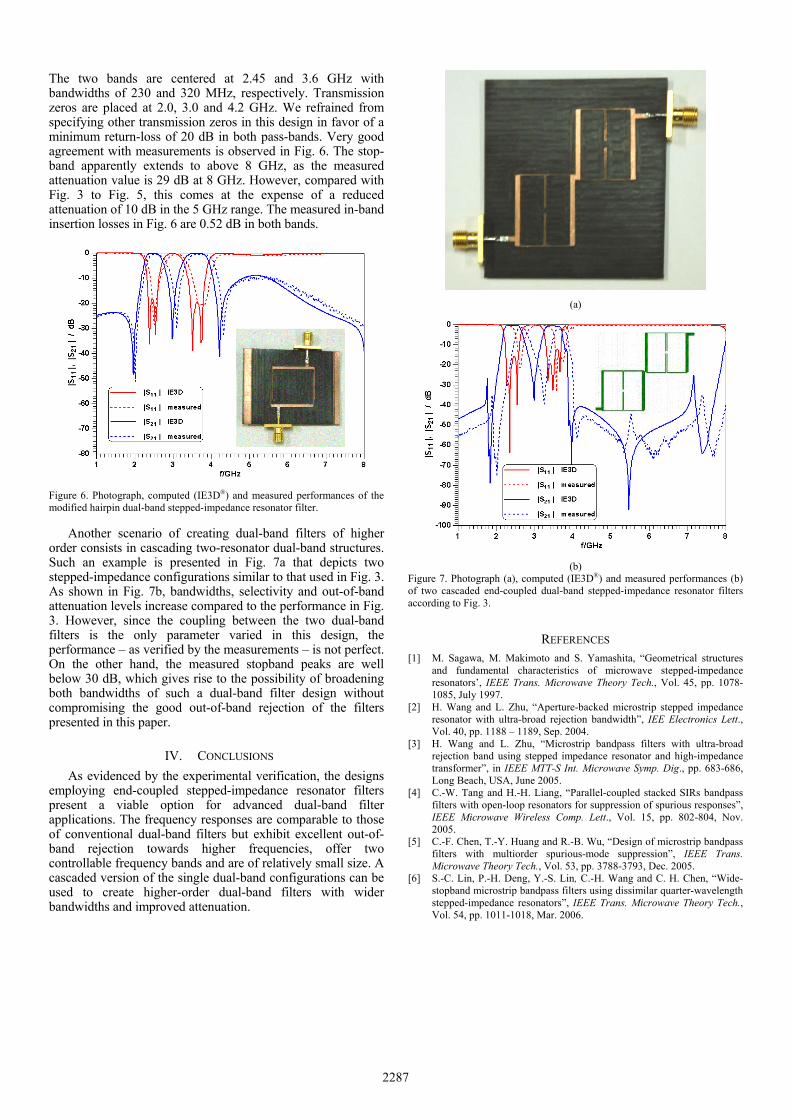
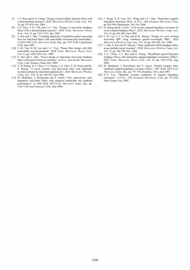
The next two figures show two variations of this design in triangular (Fig. 4) and circular (Fig. 5) stepped-impedance resonator arrangements. The photographs in the insets give an excellent account of the actual size of the prototypes. While the bandwidths and locations of the lowest three transmission zeros are similar to those in Fig. 3, the triangular structure in Fig. 4 is capable of moving the fourth transmission zero, which appears in Fig. 3 and Fig. 5 at around 5.3 GHz, upwards to 6.5 GHz. This structure thus achieves the widest stopband performance as validated by the measurements. Note that all measurements in Fig. 3 to Fig. 5 achieve return losses and stopband rejections close to or better than 20 dB. Therefore, these filters are well suited for advanced dual-band applications. The measured in-band insertion losses for Fig. 4 and Fig. 5 are 0.65, 0.73 and 0.5, 0.76 dB, respectively.
Figure 3. Photograph, computed (Ansoft Designer®) and measured responses of an end-coupled dual-band stepped-impedance resonator filter.
Figure 4. Photograph, computed (Ansoft Designer®) and measured performances of the triangular end-coupled dual-band stepped-impedance resonator filter.
Figure 5. Photograph, computed (IE3D®) and measured performances of the circular end-coupled dual-band stepped-impedance resonator filter.
The scheme of end-coupled hairpin stepped-impedance resonators is used for the dual-band filter presented in Fig. 6.
2286
The two bands are centered at 2.45 and 3.6 GHz with bandwidths of 230 and 320 MHz, respectively. Transmission zeros are placed at 2.0, 3.0 and 4.2 GHz. We refrained from specifying other transmission zeros in this design in favor of a minimum return-loss of 20 dB in both pass-bands. Very good agreement with measurements is observed in Fig. 6. The stop-band apparently extends to above 8 GHz, as the measured attenuation value is 29 dB at 8 GHz. However, compared with Fig. 3 to Fig. 5, this comes at the expense of a reduced attenuation of 10 dB in the 5 GHz range. The measured in-band insertion losses in Fig. 6 are 0.52 dB in both bands.
Figure 6. Photograph, computed (IE3D®) and measured performances of the modified hairpin dual-band stepped-impedance resonator filter.
Another scenario of creating dual-band filters of higher order consists in cascading two-resonator dual-band structures. Such an example is presented in Fig. 7a that depicts two stepped-impedance configurations similar to that used in Fig. 3. As shown in Fig. 7b, bandwidths, selectivity and out-of-band attenuation levels increase compared to the performance in Fig. 3. However, since the coupling between the two dual-band filters is the only parameter varied in this design, the performance – as verified by the measurements – is not perfect. On the other hand, the measured stopband peaks are well below 30 dB, which gives rise to the possibility of broadening both bandwidths of such a dual-band filter design without compromising the good out-of-band rejection of the filters presented in this paper.
IV. CONCLUSIONS As evidenced by the experimental verification, the designs
employing end-coupled stepped-impedance resonator filters present a viable option for advanced dual-band filter applications. The frequency responses are comparable to those of conventional dual-band filters but exhibit excellent out-of-band rejection towards higher frequencies, offer two controllable frequency bands and are of relatively small size. A cascaded version of the single dual-band configurations can be used to create higher-order dual-band filters with wider bandwidths and improved attenuation.
(a)
(b)
Figure 7. Photograph (a), computed (IE3D®) and measured performances (b) of two cascaded end-coupled dual-band stepped-impedance resonator filters according to Fig. 3.
REFERENCES [1] M. Sagawa, M. Makimoto and S. Yamashita, “Geometrical structures
and fundamental characteristics of microwave stepped-impedance resonators’, IEEE Trans. Microwave Theory Tech., Vol. 45, pp. 1078-1085, July 1997.
[2] H. Wang and L. Zhu, “Aperture-backed microstrip stepped impedance resonator with ultra-broad rejection bandwidth”, IEE Electronics Lett., Vol. 40, pp. 1188 – 1189, Sep. 2004.
[3] H. Wang and L. Zhu, “Microstrip bandpass filters with ultra-broad rejection band using stepped impedance resonator and high-impedance transformer”, in IEEE MTT-S Int. Microwave Symp. Dig., pp. 683-686, Long Beach, USA, June 2005.
[4] C.-W. Tang and H.-H. Liang, “Parallel-coupled stacked SIRs bandpass filters with open-loop resonators for suppression of spurious responses”, IEEE Microwave Wireless Comp. Lett., Vol. 15, pp. 802-804, Nov. 2005.
[5] C.-F. Chen, T.-Y. Huang and R.-B. Wu, “Design of microstrip bandpass filters with multiorder spurious-mode suppression”, IEEE Trans. Microwave Theory Tech., Vol. 53, pp. 3788-3793, Dec. 2005.
[6] S.-C. Lin, P.-H. Deng, Y.-S. Lin, C.-H. Wang and C. H. Chen, “Wide-stopband microstrip bandpass filters using dissimilar quarter-wavelength stepped-impedance resonators”, IEEE Trans. Microwave Theory Tech., Vol. 54, pp. 1011-1018, Mar. 2006.
2287
[7] J.-T. Kuo and H.-S. Cheng, “Design of quasi-elliptic function filters with a dual-passband response”, IEEE Microwave Wireless Comp. Lett., Vol. 14, pp. 472-474, Oct. 2004.
[8] J.-T. Kuo, T.-H. Yeh and C.-C. Yeh, “Design of microstrip bandpass filters with a dual-passband response”, IEEE Trans. Microwave Theory Tech., Vol. 53, pp. 1331-1337, Apr. 2005.
[9] S. Sun and L. Zhu, “Coupling dispersion of parallel-coupled microstrip lines for dual-band filters with controllable fractional pass bandwidths”, in IEEE MTT-S Int. Microwave Symp. Dig., pp. 2195-2198, Long Beach, USA, June 2005.
[10] C.-M. Tsai, H.-M. Lee and C.-C. Tsai, “Planar filter design with fully controllable second passband”, IEEE Trans. Microwave Theory Tech., Vol. 53, pp. 3429-3439, Nov. 2005.
[11] S. Sun and L. Zhu, “Novel design of dual-band microstrip bandpass filters with good in-between isolation”, in Proc. Asia-Pacific Microwave Conf., 4 pp., Suzhou, China, Dec. 2005.
[12] T.-H. Huang, H.-J. Chen, C.-S. Chang, L.-S. Chen, Y.-H. Wang and M.-P. Houng, “A novel compact ring dual-mode filter with adjustable second-passband for dual-band applications”, IEEE Microwave Wireless Comp. Lett., Vol. 16, pp. 360-362, June 2006.
[13] M. Mokhtaari, J. Bornemann and S. Amari, "New reduced-size step-impedance dual-band filters with enhanced bandwidth and stopband performance", in 2006 IEEE MTT-S Int. Microwave Symp. Dig., pp. 1181-1184, San Francisco, USA, June 2006.
[14] J. Wang, Y.-X. Guo, B.Z. Wang and L.C. Ong, “Dual-band stepped-impedance band-pass filter”, in Proc. 36th European Microwave Conf., pp. 902-904, Manchester, UK, Oct. 2006.
[15] H. Zhang and K.J. Chen, “A tri-section stepped-impedance resonator for cross-coupled bandpass filters”, IEEE Microwave Wireless Comp. Lett., Vol. 15, pp. 401-403, June 2005.
[16] C.-H. Lee, C.-I. G. Hsu and H.-K. Jhuang, “Design of a new tri-band microstrip BPF using combined quarter-wavelength SIRs”, IEEE Microwave Wireless Comp. Lett., Vol. 16, pp. 494-596, Nov. 2006.
[17] L. Zhu, S. Sun and W. Menzel, “Ultra-wideband (UWB) bandpass filters using multiple-mode resonator”, IEEE Microwave Wireless Comp. Lett., Vol. 15, pp. 796-798, Nov. 2005.
[18] Y.-C. Chiou, J.-T. Kuo and E. Cheng, “Broadband quasi-Chebyshev bandpass filters with multimode stepped-impedance resonators (SIRs)”, IEEE Trans. Microwave Theory Tech., Vol. 54, pp. 3352-3358, Aug. 2006.
[19] M. Mokhtaari, J. Bornemann and S. Amari, "Folded compact ultra-wideband stepped-impedance resonator filters", 2007 IEEE MTT-S Int. Microwave Symp. Dig., pp. 747-750, Honolulu, USA, June 2007.
[20] S.-Y. Lee, “Optimum resonant conditions of stepped impedance resonators”, in Proc. 35th European Microwave Conf., pp. 417-420, Paris, France, Oct. 2005.
2288