procedures for aggregate inspection
TRANSCRIPT

PROCEDURES FOR AGGREGATE INSPECTION
2017
Construction Field Services Division Aggregate Quality Unit


i
Engineering Manual Preamble
This manual provides guidance to administrative, engineering, and technical staff. Engineering practice requires that professionals use a combination of technical skills and judgment in decision making. Engineering judgment is necessary to allow decisions to account for unique site-specific conditions and considerations to provide high quality products, within budget, and to protect the public health, safety, and welfare. This manual provides the general operational guidelines; however, it is understood that adaptation, adjustments, and deviations are sometimes necessary. Innovation is a key foundational element to advance the state of engineering practice and develop more effective and efficient engineering solutions and materials. As such, it is essential that our engineering manuals provide a vehicle to promote, pilot, or implement technologies or practices that provide efficiencies and quality products, while maintaining the safety, health, and welfare of the public. It is expected when making significant or impactful deviations from the technical information from these guidance materials, that reasonable consultations with experts, technical committees, and/or policy setting bodies occur prior to actions within the timeframes allowed. It is also expected that these consultations will eliminate any potential conflicts of interest, perceived or otherwise. MDOT Leadership is committed to a culture of innovation to optimize engineering solutions.
The National Society of Professional Engineers Code of Ethics for Engineering is
founded on six fundamental canons. Those canons are provided below. Engineers, in the fulfillment of their professional duties, shall: 1. Hold paramount the safety, health, and welfare of the public. 2. Perform Services only in areas of their competence. 3. Issue public statement only in an objective and truthful manner. 4. Act for each employer or client as faithful agents or trustees. 5. Avoid deceptive acts.
Conduct themselves honorably, reasonably, ethically and lawfully so as to enhance the honor, reputation, and usefulness of the profession.

ii
Table of Contents CHAPTER 1 – INTRODUCTION ................................................................................. 1
INTRODUCTION ...................................................................................................... 1 DEFINITIONS ........................................................................................................... 2 HEALTH AND SAFETY ............................................................................................ 5
CHAPTER 2 – SAMPLING PROCEDURES AND EQUIPMENT ................................. 7
SAMPLING FREQUENCY ........................................................................................ 7 FIELD SAMPLE SIZE ............................................................................................... 8 SAMPLING FREQUENCY FOR SPECIALTY TESTING AT CONSTRUCTION FIELD SERVICES (CFS) LABORATORIES ....................................................................... 9 SAMPLING TOOLS ................................................................................................ 10 SAMPLING ............................................................................................................. 12 OTHER SOURCES OF CONTAMINATION ........................................................... 16 RADIAL STACKER BUILT STOCKPILES .............................................................. 19 TRUCK, FRONT END LOADER, AND DUMPSTER BUILT STOCKPILES ............ 21 ON GRADE SAMPLING ......................................................................................... 24 TRUCKS AND RAILROAD CARS .......................................................................... 26
CHAPTER 3 - MDOT AGGREGATE SUPPLIER PROGRAM .................................. 27
INTRODUCTION .................................................................................................... 27 DEFINITIONS ......................................................................................................... 27 ALL MDOT AGGREGATE SUPPLIERS ................................................................. 28 NON-PREQUALIFIED AGGREGATE SUPPLIERS ................................................ 29 PREQUALIFIED AGGREGATE SUPPLIERS ......................................................... 30 LABORATORY INSPECTIONS (PREQUALIFIED SUPPLIERS) ........................... 34 WAIVER PROCESS (ALL MDOT AGGREGATE SUPPLIERS) ............................. 35 DISTRIBUTION AND CONTACT INFORMATION .................................................. 36
CHAPTER 4 – LABORATORY SAMPLE SIZES AND SAMPLE REDUCTION ....... 39
LABORATORY SAMPLE SIZE ............................................................................... 39 MECHANICAL DEVICES ....................................................................................... 40 QUARTERING ........................................................................................................ 42 MINIATURE (MINI) STOCKPILE SAMPLING......................................................... 44 DRYING THE SAMPLE TO CONSTANT WEIGHT ................................................ 46
CHAPTER 5 – THE MECHANICAL ANALYSIS ....................................................... 49
ROUNDING PROCEDURES .................................................................................. 49 EXAMPLE PRODUCTION PROBLEM ................................................................... 49 COARSE AGGREGATE ......................................................................................... 50 LOSS BY WASHING .............................................................................................. 51 MECHANICAL WASHERS ..................................................................................... 54 SIEVING ................................................................................................................. 55 DELETERIOUS PICKS ........................................................................................... 58 DENSE-GRADED AGGREGATES ......................................................................... 59
iii
FINE AGGREGATE ................................................................................................ 59 ORGANIC PLATE NUMBER .................................................................................. 60 RUBBLE CHECK FOR CRUSHED CONCRETE AGGREGATE ............................ 60 THE AGGREGATE INSPECTION DAILY REPORT ............................................... 61 HOT MIX ASPHALT ............................................................................................... 62
CHAPTER 6 – PICKING CRUSHED AND DELETERIOUS MATERIAL................... 65
CRUSHED PARTICLES ......................................................................................... 65 DELETERIOUS AND OBJECTIONABLE PARTICLES .......................................... 65 DELETERIOUS PARTICLES.................................................................................. 66
CHAPTER 7 – OTHER TESTING PROCEDURES ................................................... 69
ORGANIC IMPURITIES TEST (THE COLORIMETRIC TEST) .............................. 69 ANGULARITY INDEX TEST (MTM 118) ................................................................ 70 UNCOMPACTED VOID CONTENT OF FINE AGGRGATE ................................... 73 AGGREGATE WEAR INDEX TESTING (MTM 111 AND MTM 112) ...................... 74 FREEZE-THAW TESTING ..................................................................................... 77 BULK DRY SPECIFIC GRAVITY ............................................................................ 80 SHRP TEST............................................................................................................ 81 FLAT PARTICLES, ELONGATED PARTICLES, OR FLAT AND ELONGATED PARTICLES ............................................................................................................ 81 SAND EQUIVALENT TEST .................................................................................... 82 RESISTANCE TO DEGRADATION OF SMALL-SIZE COARSE AGGREGATE BY ABRASION AND IMPACT IN THE LOS ANGELES MACHINE .............................. 83 MOISTURE CONTENT .......................................................................................... 85
REFERENCES .......................................................................................................... 87
iv
INDEX OF FIGURES FIGURE 1: ORDER OF PRECEDENCE FOR PROJECTS ............................................................. 8 FIGURE 2: CANVAS BAGS, PLASTIC OR STEEL PAILS CAPABLE OF HOLDING APPROXIMATELY 60
POUNDS ................................................................................................................... 10 FIGURE 3: SQUARE POINT SHOVELS (ROUND POINT SHOVELS ARE NOT ALLOWED) ............... 10 FIGURE 4: SQUARE NOSED SCOOPS ................................................................................. 11 FIGURE 5: A SAMPLE THIEF MADE FROM 1½ TO 2 INCH DIAMETER BY APPROXIMATELY 30 INCHES
LONG THIN WALL ELECTRICAL CONDUIT TO SAMPLE FINE AGGREGATES (SAND) ONLY ....... 11 FIGURE 6: 5 FOOT T-HANDLE BUCKET AUGER MADE FROM THICK WALLED GALVANIZED IRON PIPE
WITH BLADES WELDED ON EITHER A 3 OR 4 INCH OUTSIDE DIAMETER FOOT LONG THIN
WALLED PIPE ............................................................................................................ 11 FIGURE 7: SHOVEL TAKING SAMPLE .................................................................................. 12 FIGURE 8: TOP VIEW SAMPLE PATTERN “MINI” STOCKPILE AFTER BACK BLADING ................. 12 FIGURE 9: TOP VIEW BACK BLADING SAMPLING METHOD ................................................... 13 FIGURE 10: THIEF TAKING SAMPLE ................................................................................... 13 FIGURE 11: CONVEYOR CROSS SECTION .......................................................................... 14 FIGURE 12: CONVEYOR DUMPING ON GROUND WITHOUT BAFFLE ........................................ 14 FIGURE 13: CONVEYOR WITH BAFFLE ................................................................................ 15 FIGURE 14: “CONTAMINATED” CORE OF ANY STACKER BUILT STOCKPILE ............................ 15 FIGURE 15: CONVEYOR WITH TEMPLATES .......................................................................... 16 FIGURE 16: MECHANICAL SAMPLING DEVICE...................................................................... 17 FIGURE 17: CONVEYOR DUMPING INTO LOADER ................................................................. 17 FIGURE 18: SAMPLING DEVICE ......................................................................................... 18 FIGURE 19: CONE STOCKPILE PROPORTION ...................................................................... 18 FIGURE 20: TOP VIEW OF CONE STOCKPILE ...................................................................... 19 FIGURE 21: LOADING FROM CONE SHAPED STOCKPILE ....................................................... 19 FIGURE 22: LOADER REMOVING MATERIAL FROM END OF STOCKPILE .................................. 20 FIGURE 23: RADIAL STACKER STOCKPILE PROPORTIONS .................................................... 20 FIGURE 24: TYPICAL SAMPLE PATTERNS – LEFT SHOW DISTRIBUTION OF SAMPLING SITES
THROUGH THE STOCKPILE IF TEN SAMPLE POINTS ARE TAKEN FROM A RADIAL STACKER
STOCKPILE- RIGHT SHOWS DISTRIBUTION OF SAMPLING SITES THROUGH THE STOCKPILE IF
SIX SAMPLE POINTS ARE TAKEN. ................................................................................. 20 FIGURE 25: FRONT END LOADER BACKING AWAY ............................................................... 21 FIGURE 26: TRUCK BUILT STOCKPILE ................................................................................ 22 FIGURE 27: TRUCK DUMP, FRONT END LOADER, OR DUMPSTER STOCKPILE ........................ 22 FIGURE 28: DIAGONAL SAMPLE PATTERN - TOP VIEW ........................................................ 23 FIGURE 29: AGGREGATE DUMPED OVER WALL .................................................................. 23 FIGURE 30: TOP VIEW OF PAN DUMP STOCKPILE ............................................................... 24 FIGURE 31: ON GRADE SAMPLE POINTS ............................................................................ 25 FIGURE 32: MDOT AGGREGATE SUPPLIER SAMPLING FREQUENCIES .................................. 29 FIGURE 33: AASHTO AND ASTM MINIMUM LABORATORY TEST SAMPLE SIZES ................... 39 FIGURE 34: MDOT MINIMUM LABORATORY TEST SAMPLE SIZES ......................................... 39 FIGURE 35: SAMPLE SPLITTER .......................................................................................... 40 FIGURE 36: VIEW INSIDE SPLITTER ................................................................................... 41 FIGURE 37: SPLITTER FILLED – TOP VIEW ......................................................................... 41 FIGURE 38: DUMPING MATERIAL INTO SPLITTER ................................................................ 42
v
FIGURE 39: POUR RINSE WATER INTO STACKED SIEVES .................................................... 52 FIGURES 40: RINSE MATERIAL TO SIDE OF THE SIEVE AND BACK INTO THE PAN ...................... 53 FIGURE 41: MECHANICAL WASHER ................................................................................... 54 FIGURE 42: SIEVE NEST ................................................................................................... 55 FIGURE 43: MAXIMUM ALLOWABLE WEIGHT RETAINED FOR SELECTED SIEVES WITHOUT
OVERLOADING .......................................................................................................... 55 FIGURE 44: SIEVE IN BOWL FOR 1 MIN OF HAND SHAKING .................................................... 56 FIGURE 45: MARBLE STACKED SHOWING POOR INTERLOCKING ............................................ 70 FIGURE 46: IRREGULAR SHAPES SHOWING GOOD INTERLOCKING ......................................... 70 FIGURE 47: ANGULARITY INDEX TESTING FUNNEL .............................................................. 71 FIGURE 48: ANGULARITY INDEX TESTING COMPUTATION TABLE .......................................... 72 FIGURE 49: UNCOMPACTED VOIDS TEST APPARATUS ......................................................... 73 FIGURE 50: ASTM AND AASHTO OPTIONS FOR THE UNCOMPACTED VOID TEST ................. 74 FIGURE 51: WEAR TRACK WITH SPECIMEN IN PLACE ......................................................... 75 FIGURE 52: STATIC FRICTION TESTER ............................................................................... 76 FIGURE 53: PETROGRAPHIC EXAMINATION......................................................................... 76 FIGURE 54: GUIDELINES FOR APPROVAL OF SOURCES BASED ON FREEZE-THAW
TEST RESULTS ..................................................................................................... 79 FIGURE 55: PROPORTIONAL CALIPER DEVICE .................................................................... 82 FIGURE 56: SAND EQUIVALENT TEST ................................................................................ 83 FIGURE 57: LA ABRASION GRADATION B- AGGREGATE SIEVE SIZES ................................... 84 FIGURE 58: LOS ANGELES MACHINE ................................................................................. 85
1
CHAPTER 1 – INTRODUCTION INTRODUCTION This manual is designed to provide guidance for the sampling, testing, and reporting of test results for aggregate materials as standardized by the Michigan Department of Transportation (MDOT). Many, but not all, situations the technician encounters will be covered. Adherence to the procedures contained herein will ensure that tests performed by numerous individuals on the same lot of aggregate materials will be in substantial agreement. The technician conducting the inspection can be a Department employee or a consultant under contract to the Department and is the authorized representative of MDOT. It is the duty of all technicians to acquaint themselves in full with the specifications and instructions applying to their work. A thorough familiarity with the appropriate tests conducted on properly selected samples is essential for satisfactory performance of the technician’s duties. All technicians performing aggregate testing for state or federally funded projects require Michigan Certified Aggregate Technician (MCAT) training at the level appropriate for the acceptance work. A few examples and the MCAT level required are listed below:
Granular fill (Level 1)
Sub-base (Level 1)
Base (Level 1)
Concrete aggregates (Level 2)
Chip Seal aggregates (Level 2)
Bituminous aggregates (Level 2)
Sampling (Sampling Only)
The American Association of State Highway and Transportation Officials (AASHTO), the American Society for Testing and Materials (ASTM) and MDOT (Michigan Test Methods- MTMs) publish many construction standards. The Federal, state, local governmental agencies, and individual companies may develop their own standards. Agencies may adopt published standards, or parts of published standards, and rename them as a test method. Michigan Test Methods can either be stand alone, or can include modifications to other test methods. Therefore, it is important to know which testing standards are being used. Conformance to requirements can be determined by quality control testing. If something being measured does not meet, then you have nonconformance. Many of the federal and state agencies have adopted Quality Control, Quality Assurance, Total Quality Management and ISO-9000:2000 (International Organization for Standardization) programs. To be successful these programs need much more than adoption and verbal
2
commitment by management. It takes an active leadership and participation in the quality process by all members of the organization. A commitment to training is also a major component of these programs. MDOT laboratories and Industry Laboratories performing Quality Control or Quality Assurance Testing are required to meet certain training and material tracking requirements. Product quality control is a direct reflection of the organization’s leadership and attitude. This attitude also affects the external image of the organization as perceived by many individuals. Quality control is more than a product shipped or service provided. Quality control techniques can be applied to customer relations, product production, laboratory procedures and documentation, to name a few. One of the biggest challenges any technician may face is communication. The technician must know and understand how to use the applicable quality control standards. Individuals might interpret the written procedures differently when it comes to performing a specific procedure. Arguments develop about a standard’s correct interpretation and whether a procedure is being carried out correctly. Every business must establish clear communications, from the president or owner, down to the newest employee and right back up to the president or owner. Information must flow smoothly between parties, in a form acceptable and understandable to everyone. In business, the buyer and seller also should establish mutual confidence through a relationship based on clear communication. It is recommended before production starts for a source or project, schedule a meeting to discuss expectations, such as sample taking or the running of the test. Work through the first procedure together, making sure you reach agreement on how procedures will be done. Don’t lock yourself into thinking the old ways are the best ways. As technology changes, procedures change. Let your views reflect technology’s positive progress. DEFINITIONS An aggregate is a produced product having specific physical and gradational properties and is created by manipulation of material through a processing operation. The material may be from natural sand and/or gravel deposits, quarried bedrock, slag from steel mills or copper refineries, debris from mining operations, or crushed Portland cement concrete. Acceptance Tests – Tests conducted on produced material for acceptance or rejection. These tests may be conducted any time including incorporation into the finished work. These tests include MDOT’s quality assurance testing. Aggregates (Crushed Stone) – These aggregates are derived from the crushing of quarried bedrock. Aggregates (Natural Gravel) – These aggregates occur in natural, unconsolidated deposits of granular material which are derived from rock fragments such as boulders, cobbles, pebbles and granules and may be rounded, crushed or a combination of both. These deposits may be found either above or below the water table. Natural gravel aggregates consist predominantly of particles larger than the No. 4 sieve (4.75 mm).
3
*Natural Gravel Aggregates and Crushed Stone Aggregates are both included in the Standard Specifications for Construction under the definition of Natural Aggregates. Aggregate Source Inventory Number – Any source that provides aggregate materials for MDOT projects must have an ASI number, which the department uses to track the material from creation to incorporation. The first two digits of the number correspond to the county number and the last three are a numerical designation that is sequential. Every different type of material that is produced at a physical location will have its own designation, as acceptance testing is tied to the source number. ASI numbers are assigned from the Aggregate Quality Unit. You may apply for a source number by contacting your Region Materials contact or directly contacting Aggregate Quality. Coarse Aggregates – Those aggregates having particle sizes basically finer than 3 inches (75 mm) in diameter and containing negligible amounts of material finer than the No. 4 sieve (4.75 mm). The highest quality aggregates are used in Portland Cement Concrete and Hot Mix Asphalt (HMA) pavements. Crushed Portland Cement Concrete Aggregates – Those aggregates obtained by crushing salvaged Portland Cement Concrete (PCC). Coarse, dense-graded and open-graded aggregates manufactured from salvaged PCC must conform to the grading and physical requirements of the most current Standard Specifications for Construction (SSfC). There are several standard and special provisions relating to the use of crushed concrete for specific purposes. For Instance, Dense Graded Aggregate for Base course made from PCCC (Portland Cement Crushed Concrete) must not contain more than 5.0% rubble or HMA by particle count (Standard Specifications for Construction 902). Always make sure when testing material for acceptance that you have the most current and complete specifications for the material and its use. Dense-Graded Aggregates – Those aggregates composed of rock fragments finer than 1½ inches (37.5 mm) in diameter and are uniformly graded to finer than the No. 200 sieve (0.075 mm). When properly produced, these aggregates can achieve high density and stability. They are generally used for base courses and shoulders. Distribution Hub – A location that stores aggregate material for distribution that is not the source. Acceptance tests run on materials before being stored in a distribution hub are no longer valid once being placed in a distribution hub. When acceptance testing is run on material that is placed in a distribution hub, the ASI# used on the test results will correspond to the location that the material originated. Extreme care, organization and internal material tracking must be used by companies that utilize distribution hubs. Fine Aggregates – Those aggregates composed of rock fragments finer than the No. 4 sieve (4.75 mm) and coarser than the No. 200 sieve (0.075 mm). Generally, these are blended with coarse aggregates to produce Portland cement or HMA mixtures. Independent Assurance Tests – Tests conducted to evaluate both the technician’s sampling and testing procedures and the condition of the testing equipment. The initial sample is split into two halves. One half is tested by the technician and the other half is tested by the independent assurance inspector. The independent assurance inspector cannot be involved in the project and must use different equipment to test the aggregate. The Independent Assurance
4
Test will be completed and compared to the results of the Acceptance Test. These samples may be submitted to the Construction Field Services Aggregate Lab for processing if necessary. Information Tests – These tests are for information only and not intended for acceptance or rejection of aggregate materials. If a technician feels that an aggregate material has changed substantially from when it was accepted, or suspects an aggregate’s quality, the technician may perform an Information Test. Based on the test results, two courses of action are available: 1) If the material is out of specification requirements, the technician may require additional Acceptance Tests; or 2) If the material is substantially within specification requirements, no further action is required. However, these passing results do not change the sampling frequency. Intermediate Aggregate – These aggregates are passing the ½ inch sieve and retained on the No. 4 sieve. This aggregate category is used in production of aggregate blends for Optimized Gradation. Natural Sand – An accumulation of unconsolidated rock fragments or detrital particles derived from the chemical and/or physical disintegration of rocks as part of the natural weathering process which is uniformly graded and consists predominantly of particles smaller than the No. 4 sieve (4.75 mm). O.G.D.C. - Open-Graded Drainage Course Aggregate – These aggregates consist of coarse gradations, including pea gravel, with minor amounts of material finer than the No. 200 sieve (0.075 mm). They may be gravel, stone, crushed concrete or slag. They are used as drainable base material immediately below Portland Cement Concrete and HMA pavements. On-Site and Pre-Existing Material – Some jobs/projects call for re-use of material that had been incorporated into the work in a previous job at the same location, as well as call for use of material at the physical location. Prior job acceptance of material does not waive the ability or need for current acceptance testing. Much can happen to the material in the intervening time, including but not limited to, compaction, degradation and leeching of fines. Quality Control Tests – These are tests run by a material supplier for his own information and used to control the quality of material being produced, includes testing contracted by the supplier to a qualified testing lab. The frequency of testing is dependent upon the uniformity of the production operation and is stated in the supplier’s quality control plan. Each quality control plan is reviewed and approved by both the controlling MDOT Region and Construction Field Services Aggregate Quality. Slag Aggregates – Those aggregates produced as a co-product of the refining operations that turn iron and copper ore into refined metals. This includes Steel Furnace Slag, Blast Furnace Slag and Reverberatory Slag. Stone Sand – A fine aggregate produced from quarried rock which is uniformly graded and consists predominantly of particles smaller than the No. 4 sieve (4.75 mm). Stamp Sand – A fine aggregate which is the end result of a stamp-mill crushing operation. This aggregate is composed of hard, durable particles, uniformly graded in size and consists predominantly of particles smaller than the No. 4 sieve (4.75 mm).

5
HEALTH AND SAFETY It is the technician’s responsibility to make sure their personal protective equipment meets current Michigan and Federal Occupational Health and Safety Administration standards. Prior to entering a construction zone, processing area, pit or quarry, make sure you have all the necessary personal protective equipment. This equipment includes, but is not limited to; steel-toed work boots, reflective vest or clothing, hard hat, safety glasses, hearing and dust protection. When entering a construction zone, processing area, pit or quarry, check in with the person in charge of the operation. Do not enter an operation to take samples without informing someone on-site. Observe traffic patterns and park your vehicle in a safe location. Ask for permission before you climb onto equipment or venture around to observe the operation. Most quarries or pit operations require specific safety training on a yearly basis for both employees and visitors that must be completed prior to being allowed on-site. People working with equipment day after day may become too accustomed to their work environment. If their job has become a repetitive routine, they might not notice what’s going on around them. Family problems, after-work plans or an inattentive attitude can contribute to a lack of concentration and, potentially, cause an accident. Accidents cost much more than money. In addition to increased insurance premiums, medical bills, workman’s compensation, and, in the most tragic cases, death benefits, the company loses time during the accident investigation, reputation in the local community, and morale among employees. Also, it’s costly to educate new employees to take the place of their injured counterparts. In addition to safety, health issues are important to the employee. What you do today will affect your “Quality of Life” in the future. Spending the rest of your life with a work related injury or illness is not part of the “American Dream.” Working around processing equipment and in laboratories with constant exposure to dust may lead to long term lung related health issues. The Occupational Health and Safety Administration has published exposure limits. Experts generally agree that sound levels below 80 decibels (dB) are considered to be safe. However, many pieces of equipment in the work environment exceed this sound level. Exposure to a level of 85 dB over an 8 hour work day can cause permanent hearing loss. A typical leaf blower generates enough dB’s to damage your hearing is less than one minute. Repetitive activities or awkward postures can be cumulative over time and result in long term musculoskeletal problems. As you age, your body’s ability to repair itself decreases. An example of this could be the development of lower back or leg pain from repetitive lifting of heavy objects. Field samples of aggregate can exceed 50 pounds in weight and may need to be transferred from the ground to the bed of a truck, please plan accordingly. Think about your actions and what you want your “Quality of Life” in the future to be before it is too late.

6
Everyone agrees that health and safety is an important part of the work environment. In addition, health and safety standards change. Be sure you’re aware of the current government health and safety regulations and company safety policies on your job.
7
CHAPTER 2 – SAMPLING PROCEDURES AND EQUIPMENT
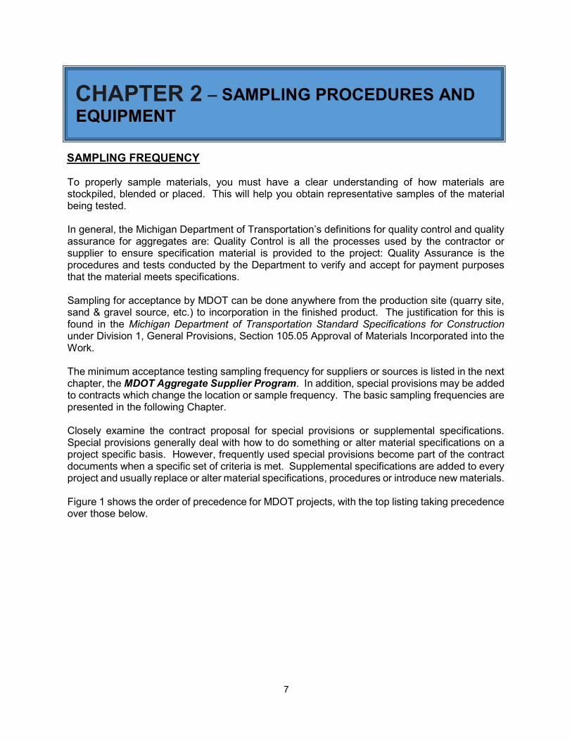
SAMPLING FREQUENCY To properly sample materials, you must have a clear understanding of how materials are stockpiled, blended or placed. This will help you obtain representative samples of the material being tested. In general, the Michigan Department of Transportation’s definitions for quality control and quality assurance for aggregates are: Quality Control is all the processes used by the contractor or supplier to ensure specification material is provided to the project: Quality Assurance is the procedures and tests conducted by the Department to verify and accept for payment purposes that the material meets specifications. Sampling for acceptance by MDOT can be done anywhere from the production site (quarry site, sand & gravel source, etc.) to incorporation in the finished product. The justification for this is found in the Michigan Department of Transportation Standard Specifications for Construction under Division 1, General Provisions, Section 105.05 Approval of Materials Incorporated into the Work. The minimum acceptance testing sampling frequency for suppliers or sources is listed in the next chapter, the MDOT Aggregate Supplier Program. In addition, special provisions may be added to contracts which change the location or sample frequency. The basic sampling frequencies are presented in the following Chapter. Closely examine the contract proposal for special provisions or supplemental specifications. Special provisions generally deal with how to do something or alter material specifications on a project specific basis. However, frequently used special provisions become part of the contract documents when a specific set of criteria is met. Supplemental specifications are added to every project and usually replace or alter material specifications, procedures or introduce new materials. Figure 1 shows the order of precedence for MDOT projects, with the top listing taking precedence over those below.
8
Figure 1: Order of Precedence for Projects
No matter how much planning is put into acquiring a sample, it all becomes worthless if the sample does not truly represent the total material. Discard any non-representative samples. FIELD SAMPLE SIZE MTM 107 Michigan Test Method for Sampling Aggregates lists minimum aggregate field sample sizes as below. Fine aggregates and Granular Material Class IIIA for independent assurance or acceptance test - approximately 25 lbs. (11 kg) which equates to roughly one half of a standard canvas sample bag. Coarse, Dense-Graded, Open-Graded aggregates and Granular Materials (except Class IIIA) for independent assurance or acceptance test - approximately 50 lbs. (25 kg) which equates to one full standard canvas sample bag. Aggregates for L.A. Abrasion test and Micro-Deval (as produced) - approximately 120 lbs. (50 kg) which equates to two full standard canvas sample bags. Aggregates for Concrete Mix Design - approximately 60 lbs. (25 kg) which equates to one full standard canvas sample bag. *For both abrasion and mix design - approximately 120 lbs. (50 kg) which equates to two full standard canvas sample bags. ASTM and AASHTO standards have guidelines for the minimum field sample sizes for laboratory testing based on the nominal maximum size of aggregates. When collecting a field sample for MDOT the minimum field sizes listed above apply unless altered by special provision or supplemental specification. Local government agencies and private contractors may have
Unique Special Provisions- Project Specific Documents
Special Provisions
Supplemental Specifications
Project Plans & Drawings (Plan Dimensions> Calculated Dimensions> Scale Dimensions)
Standard Plans
Standard Specifications
9
different requirements. Therefore, you can see the necessity of verifying proper field and test sizes before collecting the sample. SAMPLING FREQUENCY FOR SPECIALTY TESTING AT CONSTRUCTION FIELD SERVICES (CFS) LABORATORIES The following is the Michigan Department of Transportations (MDOT) frequency of sampling and testing for source approval of aggregates for use on MDOT and federally funded projects: Los Angeles (LA) Abrasion (AASHTO T 96 and Michigan Test Method 102) – Sources furnishing dense-graded, open-graded, and coarse aggregates must have a minimum of one LA Abrasion test conducted every five years. In addition,
Bituminous mixtures - if LA Abrasion is greater than 35 percent loss, testing must be conducted annually,
Crushed concrete- LA Abrasion testing must be conducted annually.
Insoluble Residue (MTM 103) – Quarried limestone and dolomite sources furnishing aggregates for dense graded aggregate and bituminous mixtures must have a minimum one insoluble residue test conducted every five years, or whenever there is a change in the deposit. Wear Track - Aggregate Wear Index (MTM 111) – Quarried, slag, and Igneous/metamorphic sources furnishing aggregates for bituminous mixtures or top coarse concrete must have a minimum one AWI wear track polishing test conducted approximate every five years. Additional testing may be warranted if major changes in deposit occur. Freeze-Thaw Durability (MTM 113, 114 and 115) – Sources furnishing coarse aggregate for Portland cement concrete must have one freeze-thaw durability test conducted every five years. Additional testing may be warranted if there are major changes in the deposit or production method. If the current bulk dry specific gravity of the sample used to develop any concrete mixture is more than 0.04 less than the bulk specific gravity of the most recent tested freeze-thaw sample or another physical property change such as the deleterious content, the aggregate will be considered to have changed characteristics and be required to have a new freeze-thaw test conducted prior to use on department projects. The aggregate producer may also request additional freeze-thaw testing if their current freeze-thaw test result on record is border-line relative to potential high quality applications, but only if there is indication that the characteristics have improved sufficient to warrant a new test. Specific Gravity testing of sources will be done yearly in the intervening years to confirm results are in line with material tested for Freeze-thaw.
10
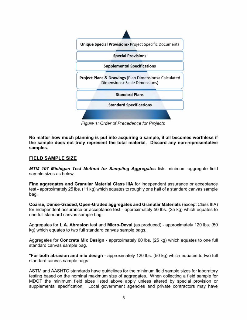
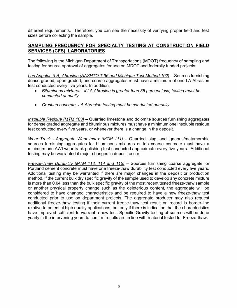
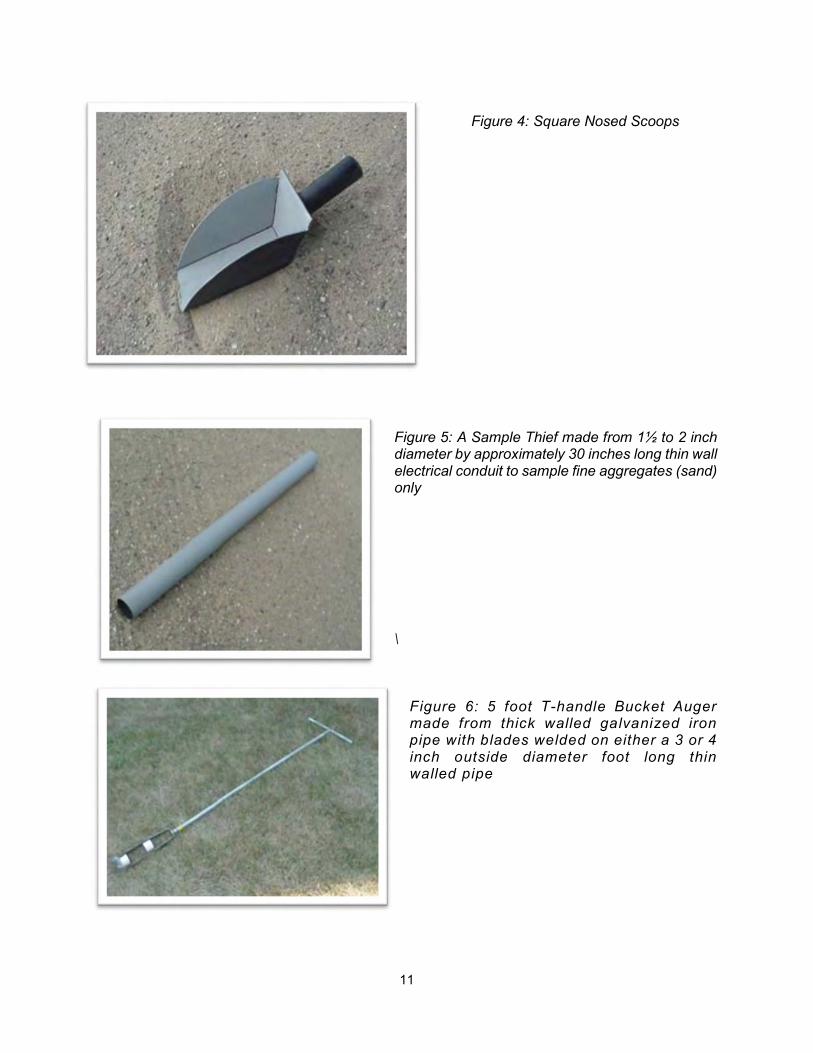
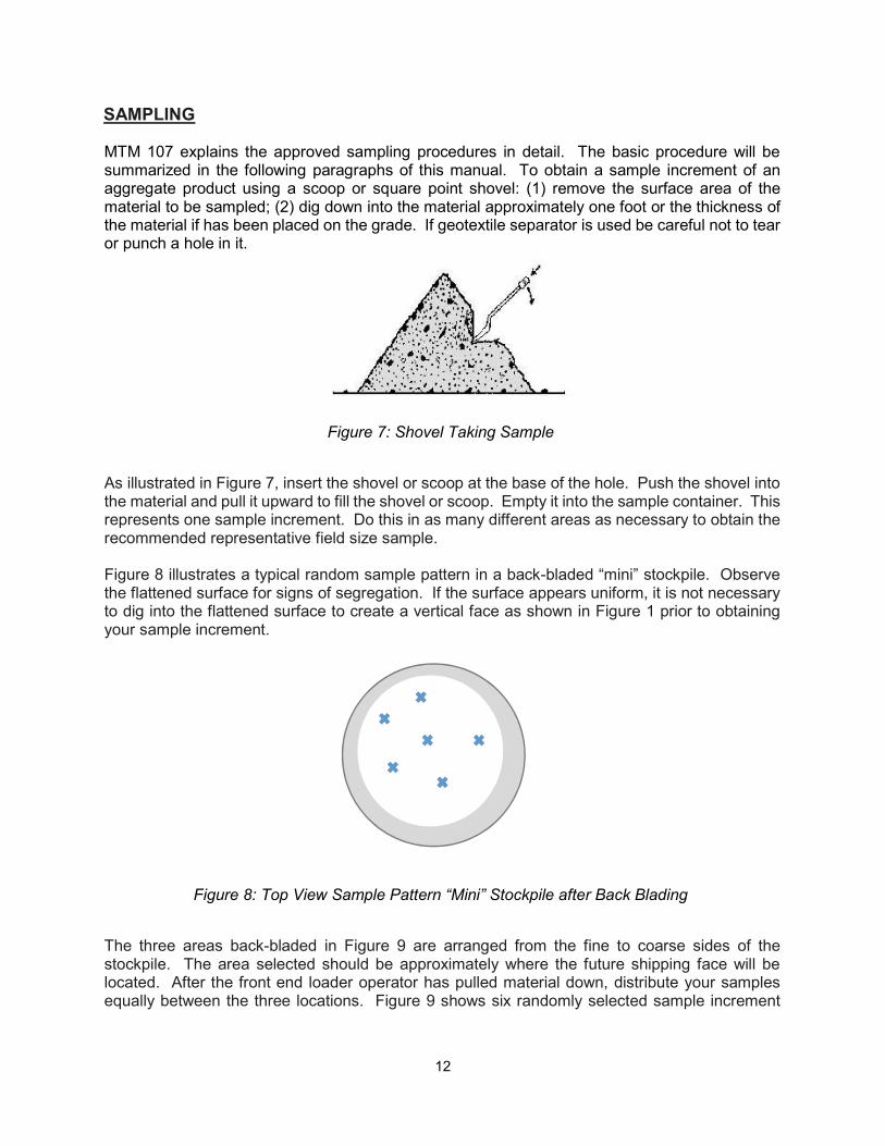
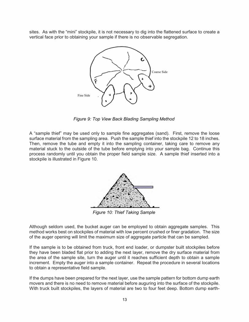
SAMPLING TOOLS Some common field sampling tools are:
Figure 2: Canvas Bags, Plastic or Steel Pails capable of holding approximately 60 pounds
Figure 3: Square Point Shovels (Round
Point Shovels are not allowed)
11
Figure 4: Square Nosed Scoops
Figure 5: A Sample Thief made from 1½ to 2 inch diameter by approximately 30 inches long thin wall electrical conduit to sample fine aggregates (sand) only \
Figure 6: 5 foot T-handle Bucket Auger made from thick walled galvanized iron pipe with blades welded on either a 3 or 4 inch outside diameter foot long thin walled pipe
12
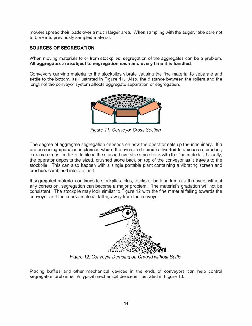
SAMPLING MTM 107 explains the approved sampling procedures in detail. The basic procedure will be summarized in the following paragraphs of this manual. To obtain a sample increment of an aggregate product using a scoop or square point shovel: (1) remove the surface area of the material to be sampled; (2) dig down into the material approximately one foot or the thickness of the material if has been placed on the grade. If geotextile separator is used be careful not to tear or punch a hole in it.
Figure 7: Shovel Taking Sample
As illustrated in Figure 7, insert the shovel or scoop at the base of the hole. Push the shovel into the material and pull it upward to fill the shovel or scoop. Empty it into the sample container. This represents one sample increment. Do this in as many different areas as necessary to obtain the recommended representative field size sample. Figure 8 illustrates a typical random sample pattern in a back-bladed “mini” stockpile. Observe the flattened surface for signs of segregation. If the surface appears uniform, it is not necessary to dig into the flattened surface to create a vertical face as shown in Figure 1 prior to obtaining your sample increment.
Figure 8: Top View Sample Pattern “Mini” Stockpile after Back Blading
The three areas back-bladed in Figure 9 are arranged from the fine to coarse sides of the stockpile. The area selected should be approximately where the future shipping face will be located. After the front end loader operator has pulled material down, distribute your samples equally between the three locations. Figure 9 shows six randomly selected sample increment
13
sites. As with the “mini” stockpile, it is not necessary to dig into the flattened surface to create a vertical face prior to obtaining your sample if there is no observable segregation.
Figure 9: Top View Back Blading Sampling Method
A “sample thief” may be used only to sample fine aggregates (sand). First, remove the loose surface material from the sampling area. Push the sample thief into the stockpile 12 to 18 inches. Then, remove the tube and empty it into the sampling container, taking care to remove any material stuck to the outside of the tube before emptying into your sample bag. Continue this process randomly until you obtain the proper field sample size. A sample thief inserted into a stockpile is illustrated in Figure 10.
Figure 10: Thief Taking Sample
Although seldom used, the bucket auger can be employed to obtain aggregate samples. This method works best on stockpiles of material with low percent crushed or finer gradation. The size of the auger opening will limit the maximum size of aggregate particle that can be sampled. If the sample is to be obtained from truck, front end loader, or dumpster built stockpiles before they have been bladed flat prior to adding the next layer, remove the dry surface material from the area of the sample site, turn the auger until it reaches sufficient depth to obtain a sample increment. Empty the auger into a sample container. Repeat the procedure in several locations to obtain a representative field sample. If the dumps have been prepared for the next layer, use the sample pattern for bottom dump earth movers and there is no need to remove material before auguring into the surface of the stockpile. With truck built stockpiles, the layers of material are two to four feet deep. Bottom dump earth-
Fine Side
Coarse Side
14
movers spread their loads over a much larger area. When sampling with the auger, take care not to bore into previously sampled material. SOURCES OF SEGREGATION When moving materials to or from stockpiles, segregation of the aggregates can be a problem. All aggregates are subject to segregation each and every time it is handled. Conveyors carrying material to the stockpiles vibrate causing the fine material to separate and settle to the bottom, as illustrated in Figure 11. Also, the distance between the rollers and the length of the conveyor system affects aggregate separation or segregation.
Figure 11: Conveyor Cross Section
The degree of aggregate segregation depends on how the operator sets up the machinery. If a pre-screening operation is planned where the oversized stone is diverted to a separate crusher, extra care must be taken to blend the crushed oversize stone back with the fine material. Usually, the operator deposits the sized, crushed stone back on top of the conveyor as it travels to the stockpile. This can also happen with a single portable plant containing a vibrating screen and crushers combined into one unit. If segregated material continues to stockpiles, bins, trucks or bottom dump earthmovers without any correction, segregation can become a major problem. The material’s gradation will not be consistent. The stockpile may look similar to Figure 12 with the fine material falling towards the conveyor and the coarse material falling away from the conveyor.
Figure 12: Conveyor Dumping on Ground without Baffle
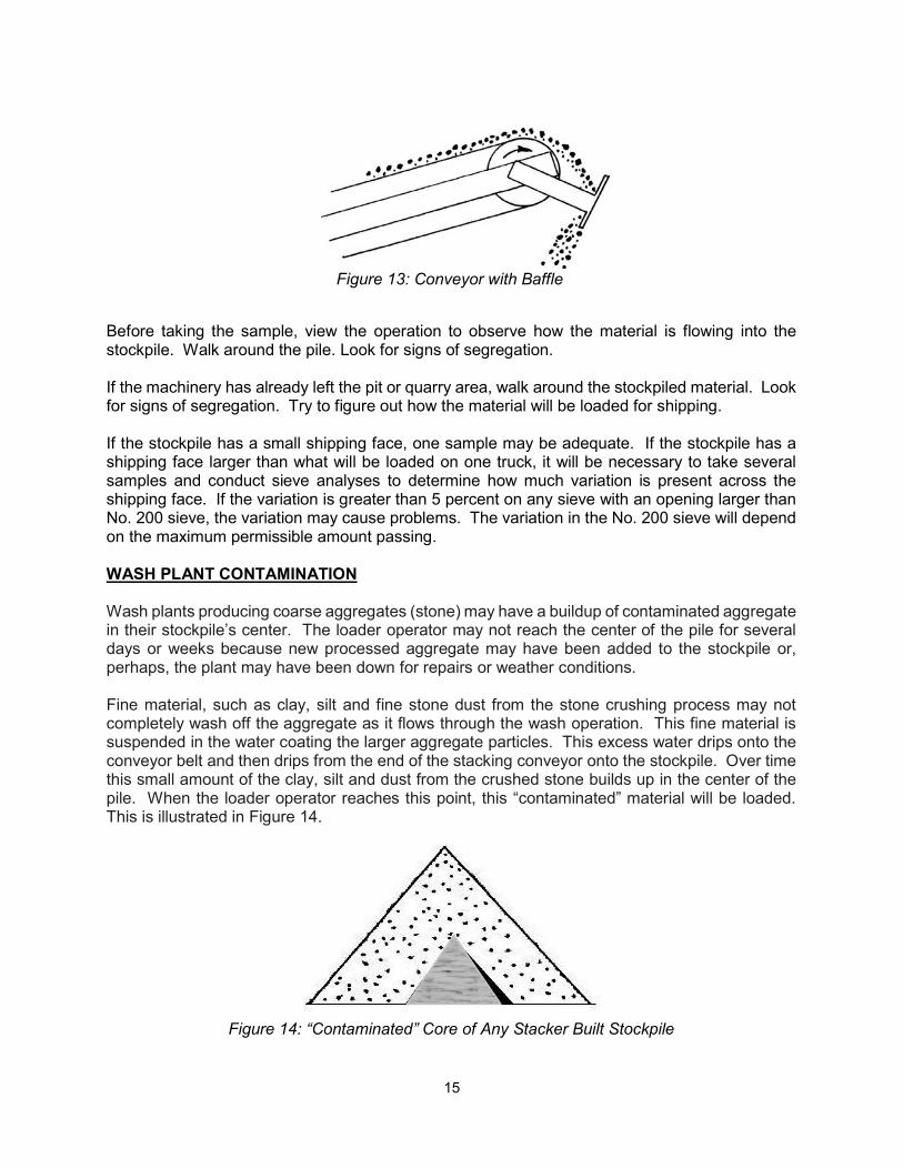
Placing baffles and other mechanical devices in the ends of conveyors can help control segregation problems. A typical mechanical device is illustrated in Figure 13.
15
Figure 13: Conveyor with Baffle
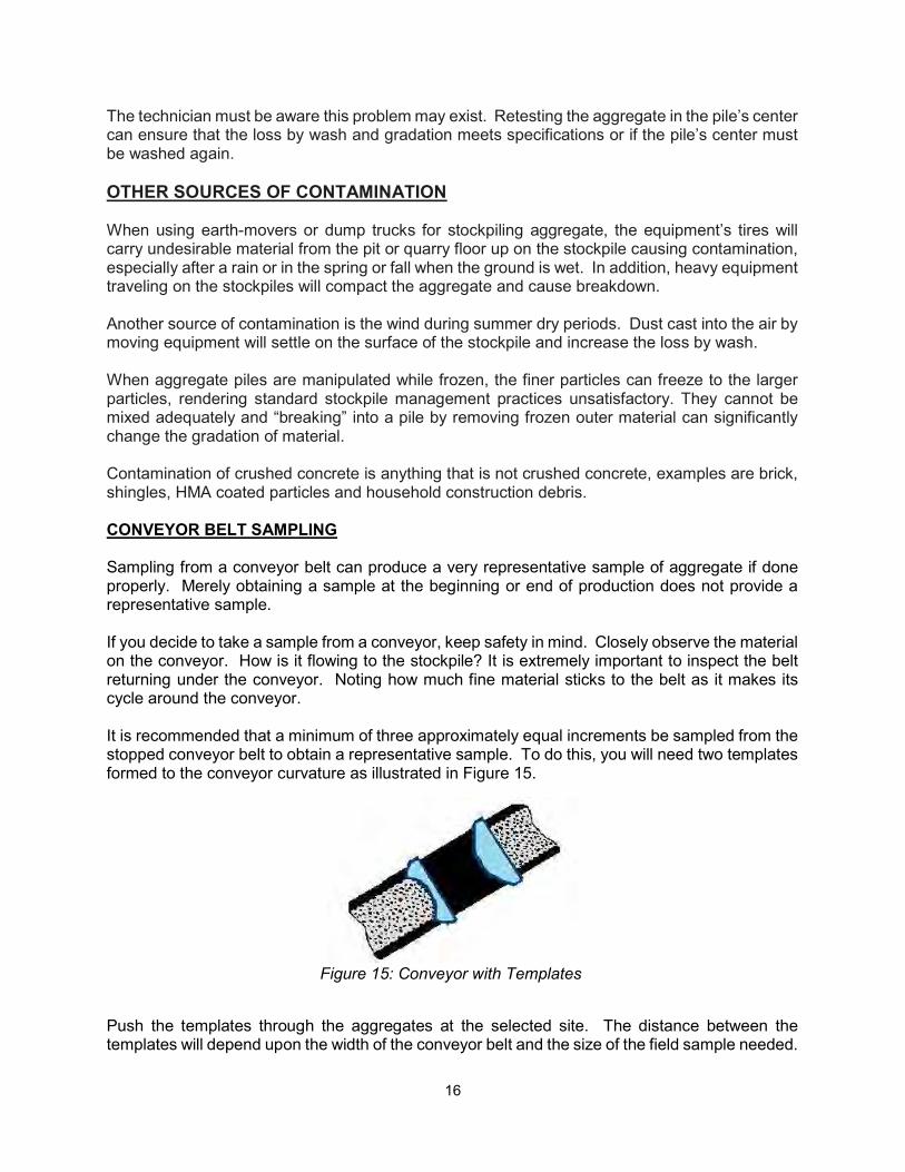
Before taking the sample, view the operation to observe how the material is flowing into the stockpile. Walk around the pile. Look for signs of segregation. If the machinery has already left the pit or quarry area, walk around the stockpiled material. Look for signs of segregation. Try to figure out how the material will be loaded for shipping. If the stockpile has a small shipping face, one sample may be adequate. If the stockpile has a shipping face larger than what will be loaded on one truck, it will be necessary to take several samples and conduct sieve analyses to determine how much variation is present across the shipping face. If the variation is greater than 5 percent on any sieve with an opening larger than No. 200 sieve, the variation may cause problems. The variation in the No. 200 sieve will depend on the maximum permissible amount passing. WASH PLANT CONTAMINATION Wash plants producing coarse aggregates (stone) may have a buildup of contaminated aggregate in their stockpile’s center. The loader operator may not reach the center of the pile for several days or weeks because new processed aggregate may have been added to the stockpile or, perhaps, the plant may have been down for repairs or weather conditions. Fine material, such as clay, silt and fine stone dust from the stone crushing process may not completely wash off the aggregate as it flows through the wash operation. This fine material is suspended in the water coating the larger aggregate particles. This excess water drips onto the conveyor belt and then drips from the end of the stacking conveyor onto the stockpile. Over time this small amount of the clay, silt and dust from the crushed stone builds up in the center of the pile. When the loader operator reaches this point, this “contaminated” material will be loaded. This is illustrated in Figure 14.
Figure 14: “Contaminated” Core of Any Stacker Built Stockpile
16
The technician must be aware this problem may exist. Retesting the aggregate in the pile’s center can ensure that the loss by wash and gradation meets specifications or if the pile’s center must be washed again. OTHER SOURCES OF CONTAMINATION When using earth-movers or dump trucks for stockpiling aggregate, the equipment’s tires will carry undesirable material from the pit or quarry floor up on the stockpile causing contamination, especially after a rain or in the spring or fall when the ground is wet. In addition, heavy equipment traveling on the stockpiles will compact the aggregate and cause breakdown. Another source of contamination is the wind during summer dry periods. Dust cast into the air by moving equipment will settle on the surface of the stockpile and increase the loss by wash. When aggregate piles are manipulated while frozen, the finer particles can freeze to the larger particles, rendering standard stockpile management practices unsatisfactory. They cannot be mixed adequately and “breaking” into a pile by removing frozen outer material can significantly change the gradation of material. Contamination of crushed concrete is anything that is not crushed concrete, examples are brick, shingles, HMA coated particles and household construction debris. CONVEYOR BELT SAMPLING Sampling from a conveyor belt can produce a very representative sample of aggregate if done properly. Merely obtaining a sample at the beginning or end of production does not provide a representative sample. If you decide to take a sample from a conveyor, keep safety in mind. Closely observe the material on the conveyor. How is it flowing to the stockpile? It is extremely important to inspect the belt returning under the conveyor. Noting how much fine material sticks to the belt as it makes its cycle around the conveyor. It is recommended that a minimum of three approximately equal increments be sampled from the stopped conveyor belt to obtain a representative sample. To do this, you will need two templates formed to the conveyor curvature as illustrated in Figure 15.
Figure 15: Conveyor with Templates
Push the templates through the aggregates at the selected site. The distance between the templates will depend upon the width of the conveyor belt and the size of the field sample needed.
17
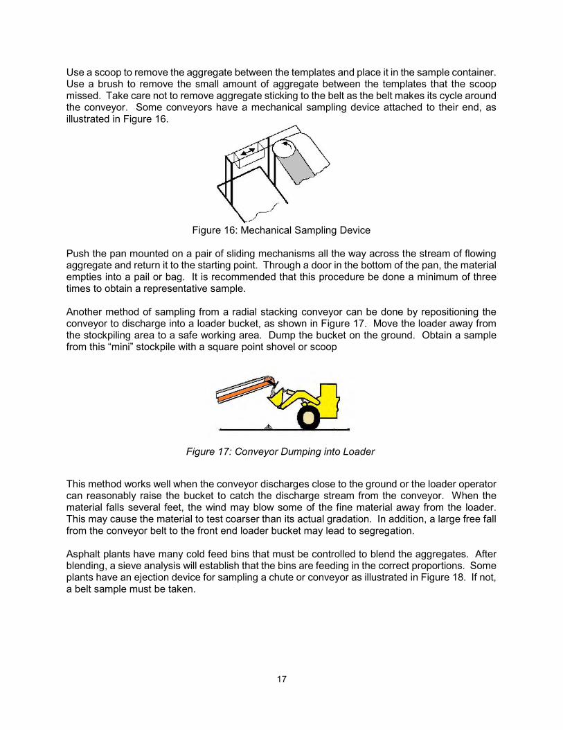
Use a scoop to remove the aggregate between the templates and place it in the sample container. Use a brush to remove the small amount of aggregate between the templates that the scoop missed. Take care not to remove aggregate sticking to the belt as the belt makes its cycle around the conveyor. Some conveyors have a mechanical sampling device attached to their end, as illustrated in Figure 16.
Figure 16: Mechanical Sampling Device
Push the pan mounted on a pair of sliding mechanisms all the way across the stream of flowing aggregate and return it to the starting point. Through a door in the bottom of the pan, the material empties into a pail or bag. It is recommended that this procedure be done a minimum of three times to obtain a representative sample. Another method of sampling from a radial stacking conveyor can be done by repositioning the conveyor to discharge into a loader bucket, as shown in Figure 17. Move the loader away from the stockpiling area to a safe working area. Dump the bucket on the ground. Obtain a sample from this “mini” stockpile with a square point shovel or scoop
Figure 17: Conveyor Dumping into Loader
This method works well when the conveyor discharges close to the ground or the loader operator can reasonably raise the bucket to catch the discharge stream from the conveyor. When the material falls several feet, the wind may blow some of the fine material away from the loader. This may cause the material to test coarser than its actual gradation. In addition, a large free fall from the conveyor belt to the front end loader bucket may lead to segregation. Asphalt plants have many cold feed bins that must be controlled to blend the aggregates. After blending, a sieve analysis will establish that the bins are feeding in the correct proportions. Some plants have an ejection device for sampling a chute or conveyor as illustrated in Figure 18. If not, a belt sample must be taken.
18
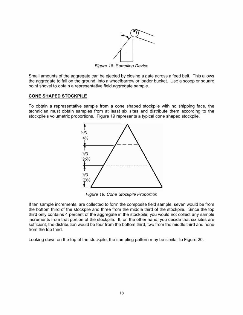
Figure 18: Sampling Device Small amounts of the aggregate can be ejected by closing a gate across a feed belt. This allows the aggregate to fall on the ground, into a wheelbarrow or loader bucket. Use a scoop or square point shovel to obtain a representative field aggregate sample. CONE SHAPED STOCKPILE To obtain a representative sample from a cone shaped stockpile with no shipping face, the technician must obtain samples from at least six sites and distribute them according to the stockpile’s volumetric proportions. Figure 19 represents a typical cone shaped stockpile.
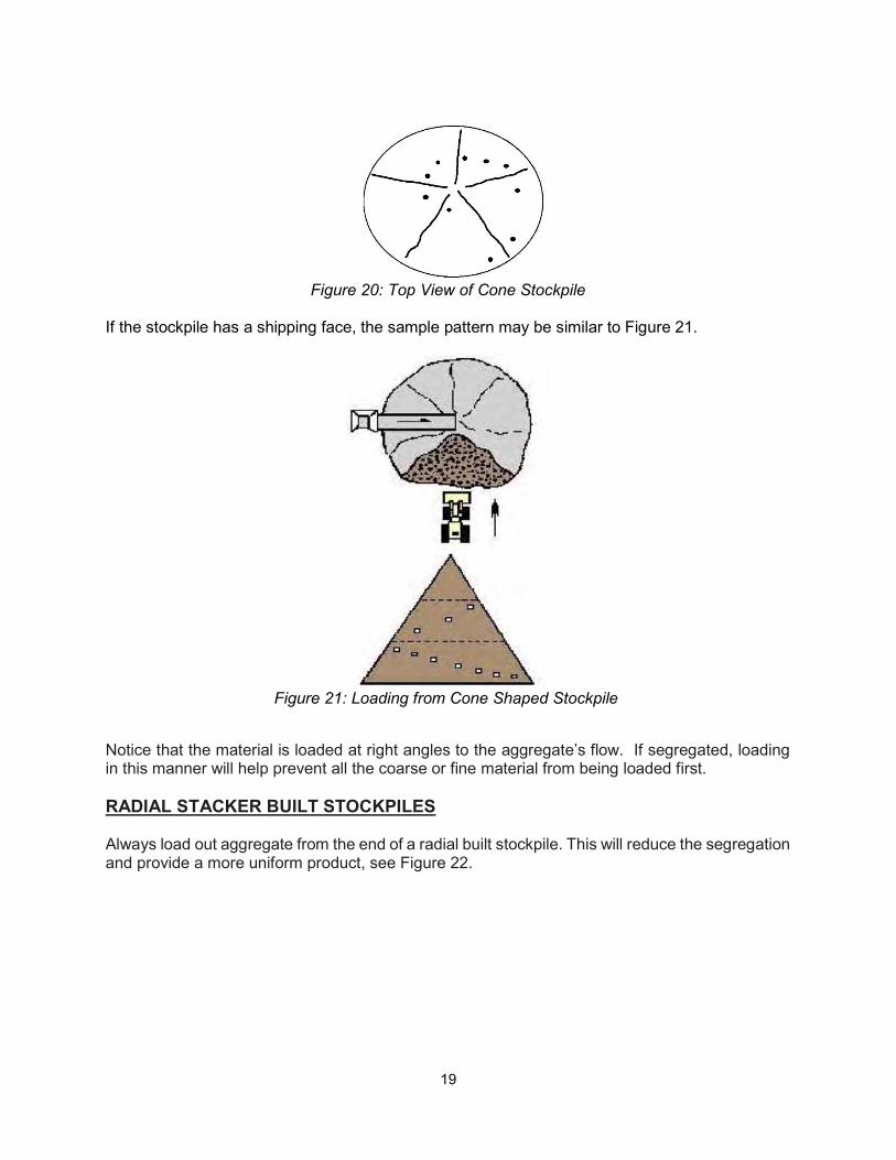
Figure 19: Cone Stockpile Proportion If ten sample increments, are collected to form the composite field sample, seven would be from the bottom third of the stockpile and three from the middle third of the stockpile. Since the top third only contains 4 percent of the aggregate in the stockpile, you would not collect any sample increments from that portion of the stockpile. If, on the other hand, you decide that six sites are sufficient, the distribution would be four from the bottom third, two from the middle third and none from the top third. Looking down on the top of the stockpile, the sampling pattern may be similar to Figure 20.
19
Figure 20: Top View of Cone Stockpile If the stockpile has a shipping face, the sample pattern may be similar to Figure 21.
Figure 21: Loading from Cone Shaped Stockpile
Notice that the material is loaded at right angles to the aggregate’s flow. If segregated, loading in this manner will help prevent all the coarse or fine material from being loaded first. RADIAL STACKER BUILT STOCKPILES Always load out aggregate from the end of a radial built stockpile. This will reduce the segregation and provide a more uniform product, see Figure 22.
20
Figure 22: Loader Removing Material from End of Stockpile
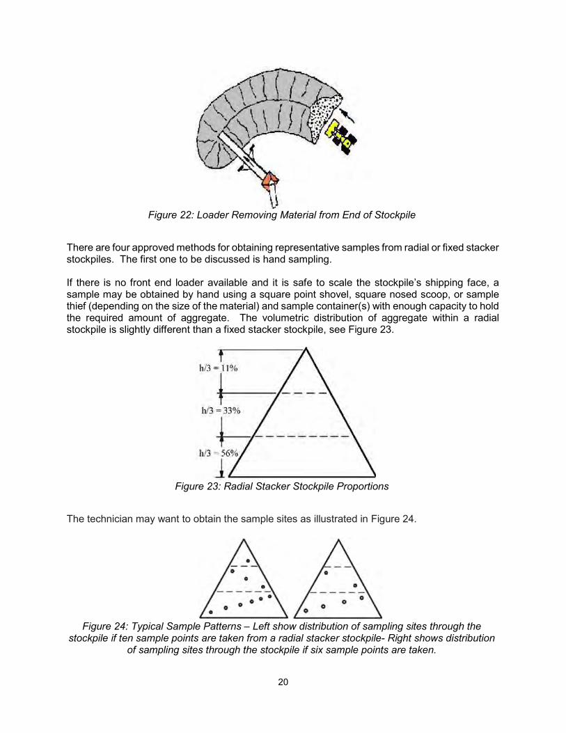
There are four approved methods for obtaining representative samples from radial or fixed stacker stockpiles. The first one to be discussed is hand sampling. If there is no front end loader available and it is safe to scale the stockpile’s shipping face, a sample may be obtained by hand using a square point shovel, square nosed scoop, or sample thief (depending on the size of the material) and sample container(s) with enough capacity to hold the required amount of aggregate. The volumetric distribution of aggregate within a radial stockpile is slightly different than a fixed stacker stockpile, see Figure 23.
Figure 23: Radial Stacker Stockpile Proportions
The technician may want to obtain the sample sites as illustrated in Figure 24.
Figure 24: Typical Sample Patterns – Left show distribution of sampling sites through the stockpile if ten sample points are taken from a radial stacker stockpile- Right shows distribution
of sampling sites through the stockpile if six sample points are taken.
21
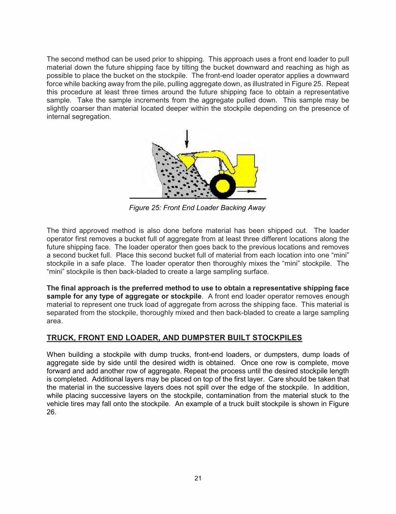
The second method can be used prior to shipping. This approach uses a front end loader to pull material down the future shipping face by tilting the bucket downward and reaching as high as possible to place the bucket on the stockpile. The front-end loader operator applies a downward force while backing away from the pile, pulling aggregate down, as illustrated in Figure 25. Repeat this procedure at least three times around the future shipping face to obtain a representative sample. Take the sample increments from the aggregate pulled down. This sample may be slightly coarser than material located deeper within the stockpile depending on the presence of internal segregation.
Figure 25: Front End Loader Backing Away
The third approved method is also done before material has been shipped out. The loader operator first removes a bucket full of aggregate from at least three different locations along the future shipping face. The loader operator then goes back to the previous locations and removes a second bucket full. Place this second bucket full of material from each location into one “mini” stockpile in a safe place. The loader operator then thoroughly mixes the “mini” stockpile. The “mini” stockpile is then back-bladed to create a large sampling surface. The final approach is the preferred method to use to obtain a representative shipping face sample for any type of aggregate or stockpile. A front end loader operator removes enough material to represent one truck load of aggregate from across the shipping face. This material is separated from the stockpile, thoroughly mixed and then back-bladed to create a large sampling area. TRUCK, FRONT END LOADER, AND DUMPSTER BUILT STOCKPILES When building a stockpile with dump trucks, front-end loaders, or dumpsters, dump loads of aggregate side by side until the desired width is obtained. Once one row is complete, move forward and add another row of aggregate. Repeat the process until the desired stockpile length is completed. Additional layers may be placed on top of the first layer. Care should be taken that the material in the successive layers does not spill over the edge of the stockpile. In addition, while placing successive layers on the stockpile, contamination from the material stuck to the vehicle tires may fall onto the stockpile. An example of a truck built stockpile is shown in Figure 26.
22
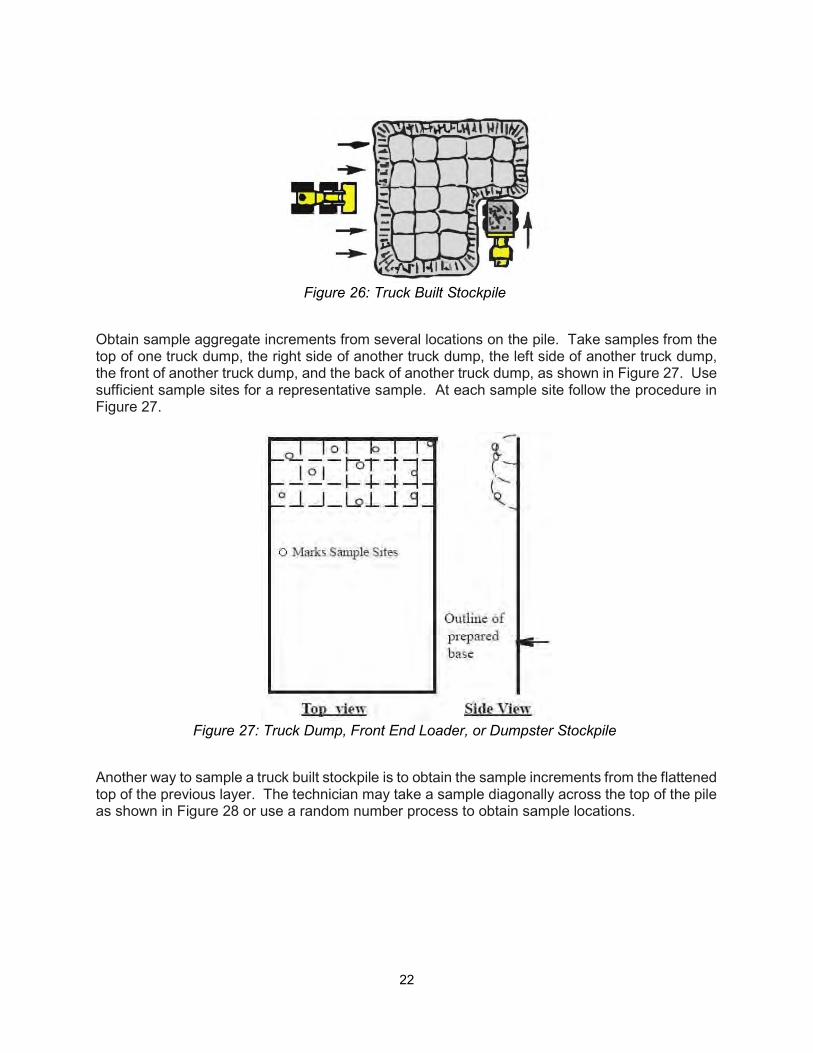
Figure 26: Truck Built Stockpile
Obtain sample aggregate increments from several locations on the pile. Take samples from the top of one truck dump, the right side of another truck dump, the left side of another truck dump, the front of another truck dump, and the back of another truck dump, as shown in Figure 27. Use sufficient sample sites for a representative sample. At each sample site follow the procedure in Figure 27.
Figure 27: Truck Dump, Front End Loader, or Dumpster Stockpile
Another way to sample a truck built stockpile is to obtain the sample increments from the flattened top of the previous layer. The technician may take a sample diagonally across the top of the pile as shown in Figure 28 or use a random number process to obtain sample locations.

23
Figure 28: Diagonal Sample Pattern - Top View
When loading the material from dump truck stockpiles, it is recommended to load the aggregate at right angles to the truck dumping. This helps to re-blend the material uniformly and consistently. Occasionally, trucks dump over pit or quarry walls. This practice can lead to segregation problems due to the pile’s height and the product’s gradation. Larger materials have a tendency to roll down the outside, accumulating at the base of the stockpile, see Figure 29.
Side View Top View
Figure 29: Aggregate Dumped Over Wall
The best solution for sampling aggregate stockpiles in this manner is to construct a “mini” stockpile. BOTTOM DUMP OR EARTH-MOVER BUILT STOCKPILES
24
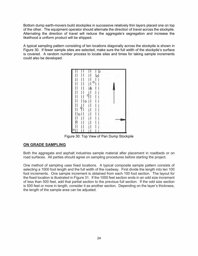
Bottom dump earth-movers build stockpiles in successive relatively thin layers placed one on top of the other. The equipment operator should alternate the direction of travel across the stockpile. Alternating the direction of travel will reduce the aggregate’s segregation and increase the likelihood a uniform product will be shipped. A typical sampling pattern consisting of ten locations diagonally across the stockpile is shown in Figure 30. If fewer sample sites are selected, make sure the full width of the stockpile’s surface is covered. A random number process to locate sites and times for taking sample increments could also be developed.
Figure 30: Top View of Pan Dump Stockpile
ON GRADE SAMPLING
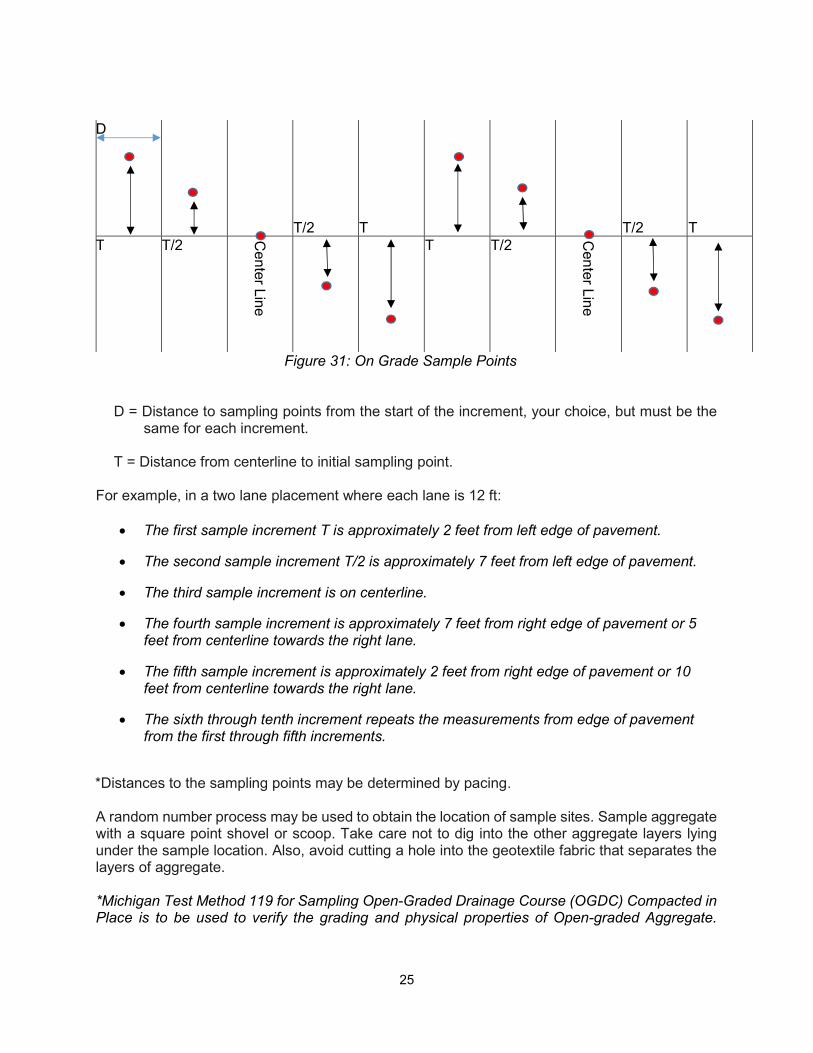
Both the aggregate and asphalt industries sample material after placement in roadbeds or on road surfaces. All parties should agree on sampling procedures before starting the project. One method of sampling uses fixed locations. A typical composite sample pattern consists of selecting a 1000 foot length and the full width of the roadway. First divide the length into ten 100 foot increments. One sample increment is obtained from each 100 foot section. The layout for the fixed location is illustrated in Figure 31. If the 1000 feet section ends in an odd size increment of less than 500 feet, add that partial section to the previous full section. If the odd size section is 500 feet or more in length, consider it as another section. Depending on the layer’s thickness, the length of the sample area can be adjusted.
25
Figure 31: On Grade Sample Points
D = Distance to sampling points from the start of the increment, your choice, but must be the
same for each increment. T = Distance from centerline to initial sampling point.
For example, in a two lane placement where each lane is 12 ft:
The first sample increment T is approximately 2 feet from left edge of pavement.
The second sample increment T/2 is approximately 7 feet from left edge of pavement.
The third sample increment is on centerline.
The fourth sample increment is approximately 7 feet from right edge of pavement or 5 feet from centerline towards the right lane.
The fifth sample increment is approximately 2 feet from right edge of pavement or 10 feet from centerline towards the right lane.
The sixth through tenth increment repeats the measurements from edge of pavement from the first through fifth increments.
*Distances to the sampling points may be determined by pacing. A random number process may be used to obtain the location of sample sites. Sample aggregate with a square point shovel or scoop. Take care not to dig into the other aggregate layers lying under the sample location. Also, avoid cutting a hole into the geotextile fabric that separates the layers of aggregate. *Michigan Test Method 119 for Sampling Open-Graded Drainage Course (OGDC) Compacted in Place is to be used to verify the grading and physical properties of Open-graded Aggregate.
D
T/2 T
T/2 T T T/2
Cen
ter Line
T T/2 C
enter Lin
e
26
Figure 31 applies to this type of sampling as well, although the value of T changes dependent on the amount of material placed before sampling. TRUCKS AND RAILROAD CARS When sampling from trucks or railroad cars, the decision will have to be made if the entire sample will be taken from one shipping unit or as a composite sample from several shipping units. Generally, samples are taken from one shipping unit. If the sample will be obtained from inside the hauling unit, randomly select at least six sites. Dig down about one foot at each location. Bring the shovel or scoop up the “vertical” face collecting one sample increment. Coarse and open-graded aggregates sampled in this manner may yield coarser gradations. If you elect to sample a hauling unit after it has discharged the aggregate, empty the material separate from any other aggregate loads. Sample this individual dump as if it was a “mini” stockpile.
27
CHAPTER 3 - MDOT AGGREGATE SUPPLIER PROGRAM
INTRODUCTION The MDOT Aggregate Supplier Program allows eligible aggregate suppliers the opportunity to provide material to both state and federally funded projects.
DEFINITIONS AASHTO Accredited Lab – A laboratory that has a Certificate of Accreditation from the AASHTO Accreditation Program (AAP). The scope of the laboratory accreditation will include Aggregate and be listed in the directory of accredited laboratories on the AASHTO re:source website (formerly known as AMRL).
Aggregate Source Inventory (ASI) – Any source that provides aggregate materials for MDOT projects will have an ASI, which the department uses to track the material from origin to application. The first two digits of the number correspond to the county number and the last three are consecutively generated (CC after an ASI indicates that crushed concrete is being produced at a preexisting source, 800 numbers in the last three digits indicate a temporary or standalone crushed concrete site). Controlling Region – The MDOT Region in which the aggregate source or distribution point is located. Construction Field Services (CFS) – Michigan Department of Transportation’s Construction Field Services Division Aggregate Quality Unit. Distribution Point (Hub) – A non-origin point of distribution, in which the material shall retain its origin based ASI#. Michigan Certified Aggregate Technician (MCAT) – Qualified aggregate testing technicians whom possess a current certification with the appropriate level for the material class that is being tested (Level One for Dense, Fine, Granular, and Open-Graded Aggregates, Level Two for Coarse and HMA Aggregates). Source (Origin) – The physical location at which the aggregate is produced by, crushing, mining, or reclamation. This is considered the “origin” of the material, and is the location to which the ASI # is assigned. Natural aggregates always originate where they are mined, not where they are processed. Supplier – An aggregate producer or distribution point having ownership of the material. Using Region – The MDOT Region where the project is located.
Warning Band – The upper and lower mechanical analysis limits specific to MDOT aggregate class.
28
ALL MDOT AGGREGATE SUPPLIERS
All MDOT Aggregate Sources will complete and adhere to the following requirements to be used on state or federally funded projects:
1. Maintain an Aggregate Source Inventory (ASI) number. The ASI number will accompany all
aggregate shipments and testing reports. Sources without an ASI number will request one by contacting both the Controlling Region and CFS Aggregate Quality with the following information:
Owner and/or Producer/Supplier name. Physical location of source including:
o legal description for quarry or sand and gravel source. o street address for all other location types (dock, plant, distribution point, etc.).
MDOT material type(s) and class(s) to be produced or distributed. Mailing address, email address, and phone number.
Note*: Tracking of aggregates from the source to the job, concrete plants or distribution
hub is the responsibility of the producer and is necessary for processing contract payments for aggregates and maintaining accurate acceptance testing frequencies (this includes amounts shipped, ASI numbers and dates of shipment, even if shipped to another location owned by the same producer).
2. Sampling and testing procedures will be in accordance with Michigan Test Methods, ASTM, and AASHTO standards as referenced in the contract documents.
3. Scales used to produce delivery tickets for aggregates on MDOT projects need to have current certification available upon request per Michigan Standard Specification for Construction section 104.01.
4. Must have a minimum of one documented passing MCAT test within 6 months of use on any
project, per material class, to be provided by the contractor to the Controlling Region and Aggregate Quality, prior to the start of supplying to state or federally funded projects.
5. Assumes responsibility for maintaining all compliance testing (Freeze Thaw, LA Abrasion,
Wear Track AWI, etc.), including request of sample before compliance expiration.
It is recommended to notify the region or Aggregate Quality and request additional testing:
- At least 4 months in advance of expiration for Freeze-Thaw testing
- At least 1 month in advance of expiration for LA Abrasion testing
- At least 6 months in advance of expiration for Aggregate Wear Track Testing
Note*: Freeze Thaw, LA Abrasion, and Wear Track testing can be collected at the same time making them on the same timetable (for most sources), reducing the burden on Suppliers with multiple sources.
29
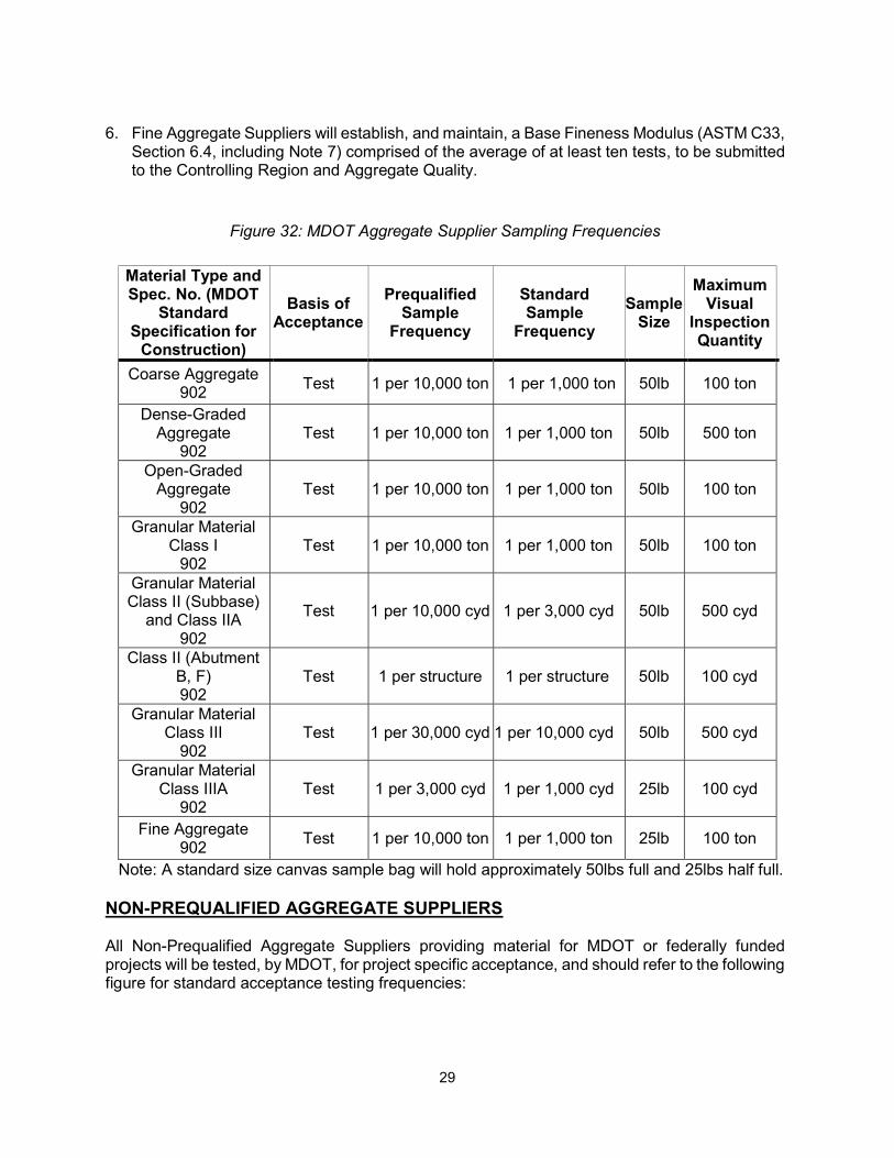
6. Fine Aggregate Suppliers will establish, and maintain, a Base Fineness Modulus (ASTM C33,
Section 6.4, including Note 7) comprised of the average of at least ten tests, to be submitted to the Controlling Region and Aggregate Quality.
Figure 32: MDOT Aggregate Supplier Sampling Frequencies
Note: A standard size canvas sample bag will hold approximately 50lbs full and 25lbs half full.
NON-PREQUALIFIED AGGREGATE SUPPLIERS All Non-Prequalified Aggregate Suppliers providing material for MDOT or federally funded projects will be tested, by MDOT, for project specific acceptance, and should refer to the following figure for standard acceptance testing frequencies:
Material Type and Spec. No. (MDOT
Standard Specification for
Construction)
Basis of Acceptance
Prequalified Sample
Frequency
Standard Sample
Frequency
Sample Size
Maximum Visual
Inspection Quantity
Coarse Aggregate 902
Test 1 per 10,000 ton 1 per 1,000 ton 50lb 100 ton
Dense-Graded Aggregate
902 Test 1 per 10,000 ton 1 per 1,000 ton 50lb 500 ton
Open-Graded Aggregate
902 Test 1 per 10,000 ton 1 per 1,000 ton 50lb 100 ton
Granular Material Class I
902 Test 1 per 10,000 ton 1 per 1,000 ton 50lb 100 ton
Granular Material Class II (Subbase)
and Class IIA 902
Test 1 per 10,000 cyd 1 per 3,000 cyd 50lb 500 cyd
Class II (Abutment B, F) 902
Test 1 per structure 1 per structure 50lb 100 cyd
Granular Material Class III
902 Test 1 per 30,000 cyd 1 per 10,000 cyd 50lb 500 cyd
Granular Material Class IIIA
902 Test 1 per 3,000 cyd 1 per 1,000 cyd 25lb 100 cyd
Fine Aggregate 902
Test 1 per 10,000 ton 1 per 1,000 ton 25lb 100 ton
30
FAILING MATERIAL RESOLUTION (NON-PREQUALIFIED)
If a quality assurance sample taken from the source or point of use does not meet specification, the Controlling Region will immediately notify the supplier and schedule resample time and location. Quality assurance sample failure and resample, during any respective project, will be handled as follows:
1. First Aggregate Resample at Source or Distribution Point - If the original sample was taken
from the shipping face at the aggregate source or distribution point, two resamples will be obtained from the same shipping face using the mini-stockpile sampling method. If the average of the original and the two resamples meet specifications, and both resamples meet specification, then the material will be approved for use and no further action is required. If the average of the original sample and two resamples does not meet specifications, or either of the resamples do not meet specification, then it will be communicated, by the Controlling Region, to the Region Construction/Project Engineer, Contractor, and the Aggregate Quality Unit (CFS) that the material is “Not for further use” on the respective project.
2. First Aggregate Resample at Point of Use - If the original sample was taken from the point of use, two resamples will be obtained from either the same location or another point of use, to be decided by the Controlling Region, provided the aggregate is from the same source. If the average of the original and two resamples meets specifications, and both resamples meet specification, then the material will be approved for use and no further action is required. If the average of the original sample and two resamples do not meet specifications, or either of the resamples does not meet specification, then it will be communicated, by the Controlling Region, to the Region Construction/Project Engineer, Contractor, Supplier, and the Aggregate Quality Unit (CFS) that the material is “Not for further use” on the respective project. Future use of the source will be evaluated on a case by case basis.
3. Second Quality Assurance Failure (source, distribution point, and point of use) - If any second
quality assurance sample (not including resamples) does not meet specifications, then it will be communicated, by the Controlling Region, to the Region Construction/Project Engineer, Contractor, Supplier, and the Aggregate Quality Unit (CFS) that the material is “Not for further use” on the respective project. Future use of the source will be evaluated on a case by case basis.
PREQUALIFIED AGGREGATE SUPPLIERS “Prequalification” in the MDOT Aggregate Supplier Program is a partnership between MDOT regions and aggregate suppliers, exchanging documented Quality Control and certified testing personnel by suppliers, for a reduction in acceptance testing and increased failing material resolution from MDOT Aggregate Quality.
Note: PREQUALIFICATION is the status of the SUPPLIER and makes no representation of actual material quality.
PROCESS OF APPLICATION Suppliers interested in applying to become Prequalified will complete the following: 1. Submit a letter to the Controlling Region and CFS Aggregate Quality Unit stating the intent to
be become a Prequalified Aggregate Supplier. The letter will include the following items:
31
Company Name. Source (Pit) Name(s). Aggregate Source Inventory #(s). Primary Contact, including phone and email. Secondary Contact (if applicable), including phone and email. Location of testing facility (contracted testers will be subject to section 3.4). All anticipated Michigan aggregate series (MDOT designation). List of all MCAT personnel (at least one is required to be considered for
Prequalification).
2. Submit a Quality Control Plan (QCP) to be reviewed and approved by CFS and the Controlling Region. A QCP will include all items required in the letter of request and the following information:
a. Production sampling frequency and location, including:
• Where and when samples are obtained.
• Approximate amount of material covered by each test.
b. Document major events including, but not limited to, plant start up, screen changes,
and breakdowns which may affect aggregate production.
c. Produce a control chart, posted in a prominent location, kept up to date, and stating the intervals of each update. If the supplier does not produce or supply enough material for the test results to be statistically significant no control chart is required.
d. Establish an Action Plan, for suppliers who produce their own aggregates, to be used
when material is outside the warning band or specification limits, will include at least the following:
- List operational procedures to be followed to bring the material back within the warning band or specification limits.
- State when and where sampling and testing the new production will occur.
- When the material is outside the specification limits; halt or divert production from adding to the existing stockpile until test results indicate the material is within specification limits.
- Describe the method that will be used to distinguish the failing material from the specification material.
e. Establish an Action Plan for docks, concrete plants, or transfer points when a failing
result occurs will include at least the following:
32
- Remove the failing aggregate from the stockpile until specification material is
located. - Increase the testing frequency for the aggregate remaining in the stockpile. - Describe the method that will be used to distinguish the failing material from the
specification material.
f. Specify the Load-out (Shipping) sampling and testing frequency.
g. Detail document retention policy, particularly, but not limited to, quality control tests and MDOT or federally funded material shipment quantities (weekly summaries are acceptable). All documents must be retained for a minimum of 3 years.
3. Must complete an initial laboratory inspection that meets the requirements of section. The Supplier will be notified by the Aggregate Quality Unit once the application process has been approved by both Aggregate Quality and the Controlling Region.
SUPPLIER DOCUMENTATION AND QUALITY CONTROL
Prequalified Aggregate Suppliers will remain current on all of the following points of documentation:
1. Adhere to all points of accountability in the agreed upon QCP. 2. Formally notify the Controlling Region’s Materials Supervisor and Aggregate Quality by
fax/email on or before the first aggregate shipment for each calendar year. 3. Accompany each aggregate shipment delivered to a project or concrete plant with a delivery
ticket containing the MDOT aggregate source number, date of shipment, control section number, job number, concrete plant number (if applicable), Michigan series number and class letter of aggregate, weight or volume shipped, supplier's name, telephone number and location. In addition, print or stamp the following statement on each trip ticket:
"I attest that aggregate as delivered from this prequalified source meets specification requirements for listed Michigan series and class for quantity stated.” Date Signature______________________________________
This statement must be signed (hand, electronic, or otherwise) and dated by an accountable authorized company representative. Lack of delivery tickets will result in rejection of the aggregate. The statement on each delivery ticket, is to be provided by the supplier, and represents the results of quality control testing. This statement does not signify acceptance by MDOT.
4. Generate weekly summary, regardless if any material is shipped, and fax or email it to both
the Controlling Region and Aggregate Quality by the close of business on Monday of the week following shipment. The weekly summary report will have the following information:
- Date generated - Sequentially numbered - Include the following information for each type of aggregate:
33
ASI number(s) Quantity Date shipped Destination (MDOT project number, concrete plant number/name, or purchase
order number)
When the supplier does not anticipate any aggregate shipments to MDOT or federal aid projects for at least one full business week, they may indicate “Until further notice, no state work” on the last weekly summary. Once this report is transmitted, the supplier will not be required to continue sending the weekly summaries until shipping resumes, at which point the supplier will contact the Controlling Region and Aggregate Quality on or before time of shipment. Additionally, at the close of the construction season, the supplier may indicate “Last shipment for the season” on the weekly summary report. Once this report is transmitted, the supplier will not be required to continue sending the weekly summaries until the start of the next construction season.
5. Maintain an MCAT certified technician (employed or contracted) to conduct all sampling and
testing on material for MDOT or federally funded projects MDOT QUALITY ASSURANCE TESTING (PREQUALIFIED SUPPLIER)
All Prequalified Aggregate Suppliers providing material for MDOT or federally funded projects will be tested, by MDOT, for quality assurance (reduced acceptance). FAILING MATERIAL RESOLUTION (PREQUALIFIED SUPPLIER)
When quality assurance samples taken from the shipping face or point of use do not meet specifications, the controlling Region will immediately notify the supplier and inform the supplier of the resample time and location. In addition, the supplier’s quality control tests will be reviewed.
1. Aggregate Resample at Source or Distribution Point – If the original sample was taken from
the stockpile’s shipping face at the aggregate’s source, or distribution point, two resamples will be obtained from the same stockpile’s shipping face using the mini-stockpile sampling method. If the average of the original and two resamples meets specifications, and both resamples meet specification, then the material will be approved for use and no further action is required. If the average of the original sample and two resamples do not meet specifications, or either of the resamples does not meet specification, the failing material will be removed from the stockpile or production will be diverted elsewhere, and both the Supplier and the Controlling Region will then develop a plan of corrective action. If the corrective action plan fails to resolve material quality, it will then be communicated, by the Controlling Region, to the Region Construction/Project Engineer, Contractor, and Aggregate Quality Unit that the material is “Not for further use”. Multiple failing corrective action plans may result in removal from the Prequalified Aggregate Supplier Program.
2. Aggregate Resample at Point of Use – If the original sample was taken from the point of use, two resamples will be obtained from either the same location or another point of use, provided the aggregate is from the same source. If the average of the original and two resamples meets specifications, and both resamples meet specification, then the material will be approved for use and no further action is required. If the average of the original sample and two resamples does not meet specifications, or either of the resamples do not meet
34
specification, the supplier will not be allowed to ship the disputed material and both the Supplier and the Controlling Region will then develop a plan of corrective action. If the corrective action plan fails to resolve material quality, it will then be communicated, by the Controlling Region, to the Region Construction/Project Engineer, Contractor, and Aggregate Quality Unit that the material is “Not for further use”. Multiple failing corrective action plans may result in removal from the Prequalified Aggregate Supplier Program.
MDOT DOCUMENTATION AND QUALITY ASSURANCE Controlling Regions will assure supplier compliance by maintaining the following documentation and quality assurance procedures:
Retain a copy of each supplier’s weekly summaries for a minimum of 5 years and
quantify, in a documented fashion, the quantities supplied to all MDOT and federally funded projects.
Retain a copy of each quality assurance (reduced acceptance) test for a minimum of 5 years.
Aggregate Quality will maintain the following documentation and communicate the following:
Retain a copy of each supplier’s weekly summaries for a minimum of 5 years and
quantify, in a documented fashion, the quantities supplied to all MDOT and federally funded projects.
Assure a biennial laboratory inspection (by either the Controlling Region or Aggregate Quality) of each Prequalified Aggregate Supplier (see 3.4).
Draft a formal letter in the instance of all approved amendments to QCP’s (including pit changes), lab inspection reports, acceptance into the program, etc., and deliver to affected Controlling Regions and Suppliers, and retain a copy for records.
LABORATORY INSPECTIONS (PREQUALIFIED SUPPLIERS) All suppliers, or consultants contracted for sampling/testing by suppliers, will be required to complete a laboratory inspection to be eligible for prequalification. The laboratory inspection requirement may be waived if the laboratory is an AASHTO accredited laboratory. Once Prequalified, laboratory inspections will be conducted on a biennial frequency and will be administered by the Aggregate Quality Unit. LABORATORY INSPECTION REQUIREMENTS The laboratory must meet Michigan Occupational Safety and Health Administration Standards (MiOSHA). The following are the procedures/equipment to be evaluated per their respective ASTM/MTM, when applicable:
Sampling (MTM 107) o equipment o “mini” stockpile method
35
o sample size
Scale (ASTM C136) o model o calibration date o level
Reduction Method (ASTM C702)
o sample splitter o lab sample size
Drying Method (MTM 108, MTM 109)
o stove top, oven, burner, or other o duration (constant weight or paper curl)
Shaking Method (MTM 109, ASTM C136)
o shaker or hand o sieve compliance (ASTM E11)
If an Independent Assurance Test (IAT) has been completed on a Supplier within the previous year of the scheduled laboratory inspection, the applicable results may be used in place of the requirements listed above. If an IAT has not been completed, or is due on a Prequalified Supplier, one will be conducted during the laboratory inspection.
WAIVER PROCESS (ALL MDOT AGGREGATE SUPPLIERS)
Requirements of both Prequalified and Non-Prequalified Suppliers may be waived only at the request of the Controlling Region, particularly, but not limited to, quality assurance test frequencies.
PROCEDURE FOR WAIVER REQUEST
Controlling Regions will submit a formal letter of request to the Aggregate Quality Unit Engineer containing the following:
Supplier Name and ASI pit number(s) Material Class (if request is class specific) Requirement to be waived Justification for waiver (test proficiency, etc.) Definition of new requirement (if applicable) Duration of waiver
Once approved, a letter stating the new terms of the requirement will be delivered to the Controlling Region, the supplier, and in all pertinent project files (in the instance the waiver amends project specific requirements such as testing frequency).
WAIVER JUSTIFICATION
The primary justification(s) for waiving aggregate testing requirements for Non-Prequalified Suppliers are, but not limited to, the following:

36
90% passing assurance test proficiency over either 24 months or 30,000 tons. 100% passing assurance test proficiency over either 12 months or 10,000 tons.
The following are the primary justification(s) for waiving aggregate testing requirements for Prequalified Suppliers:
90% passing assurance test proficiency over either 12 months or 30,000 tons.
DISTRIBUTION AND CONTACT INFORMATION Submit all documentation to Aggregate Quality and the Controlling Region Materials Contact as required (the following contact information was updated as of 08/10/2017):
Michigan Department of Transportation Construction Field Services Division Aggregate Quality-PASP 8885 Ricks Road P.O. Box 30049 Lansing, MI 48909 Fax: 517-636-5363 [email protected]
Weekly summary reports shall be submitted to Aggregate Quality via email at [email protected] and the respective region contact listed below Questions or concerns can be directed either to the respective Controlling Region or the Aggregate Quality Engineer, whose information is as follows:
Christopher L. Gembel MDOT Aggregate Quality Aggregate Quality Engineer MDOT Aggregate Supplier Program Coordinator [email protected] Office (517) 636-0280 Cell (517) 243-2044
CONTROLLING REGION CONTACT INFORMATION
Superior Region Brian Johnson 517-937-0045 [email protected] North Region Steve Solak 989-370-2322 [email protected] Grand Region Twila Geiger 616-240-3996 [email protected] Bay Region Brian Hunt 989-239-0905 [email protected] Southwest Region Jeff Bennett 269-207-8301 [email protected] University Region Steve Hawker 517-937-1650 [email protected] Metro Region Mike Cornacchia 248-361-6923 [email protected]

37

38
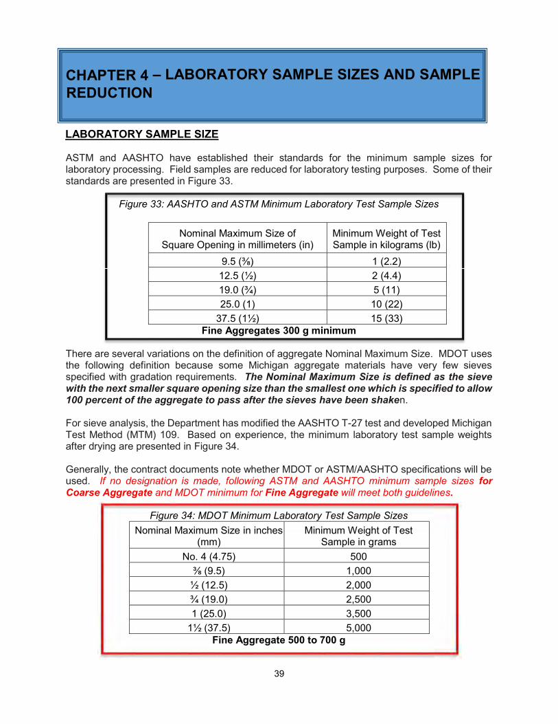
39
CHAPTER 4 – LABORATORY SAMPLE SIZES AND SAMPLE REDUCTION
LABORATORY SAMPLE SIZE ASTM and AASHTO have established their standards for the minimum sample sizes for laboratory processing. Field samples are reduced for laboratory testing purposes. Some of their standards are presented in Figure 33.
Figure 33: AASHTO and ASTM Minimum Laboratory Test Sample Sizes
Nominal Maximum Size of Square Opening in millimeters (in)
Minimum Weight of Test Sample in kilograms (lb)
9.5 (⅜) 1 (2.2)
12.5 (½) 2 (4.4)
19.0 (¾) 5 (11)
25.0 (1) 10 (22)
37.5 (1½) 15 (33) Fine Aggregates 300 g minimum
There are several variations on the definition of aggregate Nominal Maximum Size. MDOT uses the following definition because some Michigan aggregate materials have very few sieves specified with gradation requirements. The Nominal Maximum Size is defined as the sieve with the next smaller square opening size than the smallest one which is specified to allow 100 percent of the aggregate to pass after the sieves have been shaken. For sieve analysis, the Department has modified the AASHTO T-27 test and developed Michigan Test Method (MTM) 109. Based on experience, the minimum laboratory test sample weights after drying are presented in Figure 34. Generally, the contract documents note whether MDOT or ASTM/AASHTO specifications will be used. If no designation is made, following ASTM and AASHTO minimum sample sizes for Coarse Aggregate and MDOT minimum for Fine Aggregate will meet both guidelines.
Figure 34: MDOT Minimum Laboratory Test Sample Sizes
Nominal Maximum Size in inches (mm)
Minimum Weight of Test Sample in grams
No. 4 (4.75) 500
⅜ (9.5) 1,000
½ (12.5) 2,000
¾ (19.0) 2,500
1 (25.0) 3,500
1½ (37.5) 5,000 Fine Aggregate 500 to 700 g
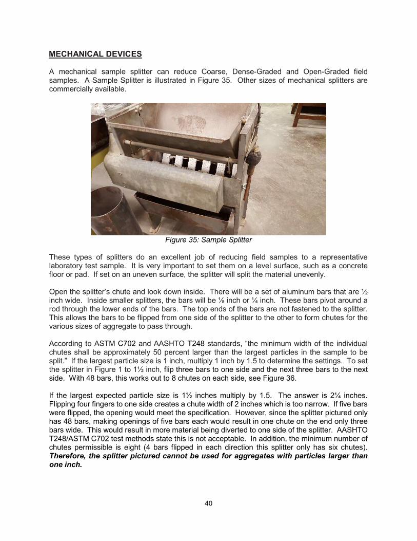
40
MECHANICAL DEVICES A mechanical sample splitter can reduce Coarse, Dense-Graded and Open-Graded field samples. A Sample Splitter is illustrated in Figure 35. Other sizes of mechanical splitters are commercially available.
Figure 35: Sample Splitter
These types of splitters do an excellent job of reducing field samples to a representative laboratory test sample. It is very important to set them on a level surface, such as a concrete floor or pad. If set on an uneven surface, the splitter will split the material unevenly. Open the splitter’s chute and look down inside. There will be a set of aluminum bars that are ½ inch wide. Inside smaller splitters, the bars will be ⅛ inch or ¼ inch. These bars pivot around a rod through the lower ends of the bars. The top ends of the bars are not fastened to the splitter. This allows the bars to be flipped from one side of the splitter to the other to form chutes for the various sizes of aggregate to pass through. According to ASTM C702 and AASHTO T248 standards, “the minimum width of the individual chutes shall be approximately 50 percent larger than the largest particles in the sample to be split.” If the largest particle size is 1 inch, multiply 1 inch by 1.5 to determine the settings. To set the splitter in Figure 1 to 1½ inch, flip three bars to one side and the next three bars to the next side. With 48 bars, this works out to 8 chutes on each side, see Figure 36. If the largest expected particle size is 1½ inches multiply by 1.5. The answer is 2¼ inches. Flipping four fingers to one side creates a chute width of 2 inches which is too narrow. If five bars were flipped, the opening would meet the specification. However, since the splitter pictured only has 48 bars, making openings of five bars each would result in one chute on the end only three bars wide. This would result in more material being diverted to one side of the splitter. AASHTO T248/ASTM C702 test methods state this is not acceptable. In addition, the minimum number of chutes permissible is eight (4 bars flipped in each direction this splitter only has six chutes). Therefore, the splitter pictured cannot be used for aggregates with particles larger than one inch.
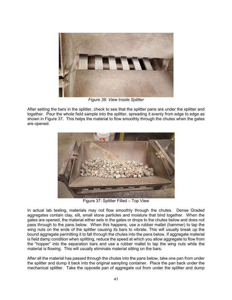
41
Figure 36: View Inside Splitter
After setting the bars in the splitter, check to see that the splitter pans are under the splitter and together. Pour the whole field sample into the splitter, spreading it evenly from edge to edge as shown in Figure 37. This helps the material to flow smoothly through the chutes when the gates are opened.
Figure 37: Splitter Filled – Top View
In actual lab testing, materials may not flow smoothly through the chutes. Dense Graded aggregates contain clay, silt, small stone particles and moisture that bind together. When the gates are opened, the material either sets in the gates or drops to the chutes below and does not pass through to the pans below. When this happens, use a rubber mallet (hammer) to tap the wing nuts on the ends of the splitter causing its bars to vibrate. This will usually break up the bound aggregate permitting it to fall through the chutes into the pans below. If aggregate material is field damp condition when splitting, reduce the speed at which you allow aggregate to flow from the “hopper” into the separation bars and use a rubber mallet to tap the wing nuts while the material is flowing. This will usually eliminate material sitting on the bars. After all the material has passed through the chutes into the pans below, take one pan from under the splitter and dump it back into the original sampling container. Place the pan back under the mechanical splitter. Take the opposite pan of aggregate out from under the splitter and dump
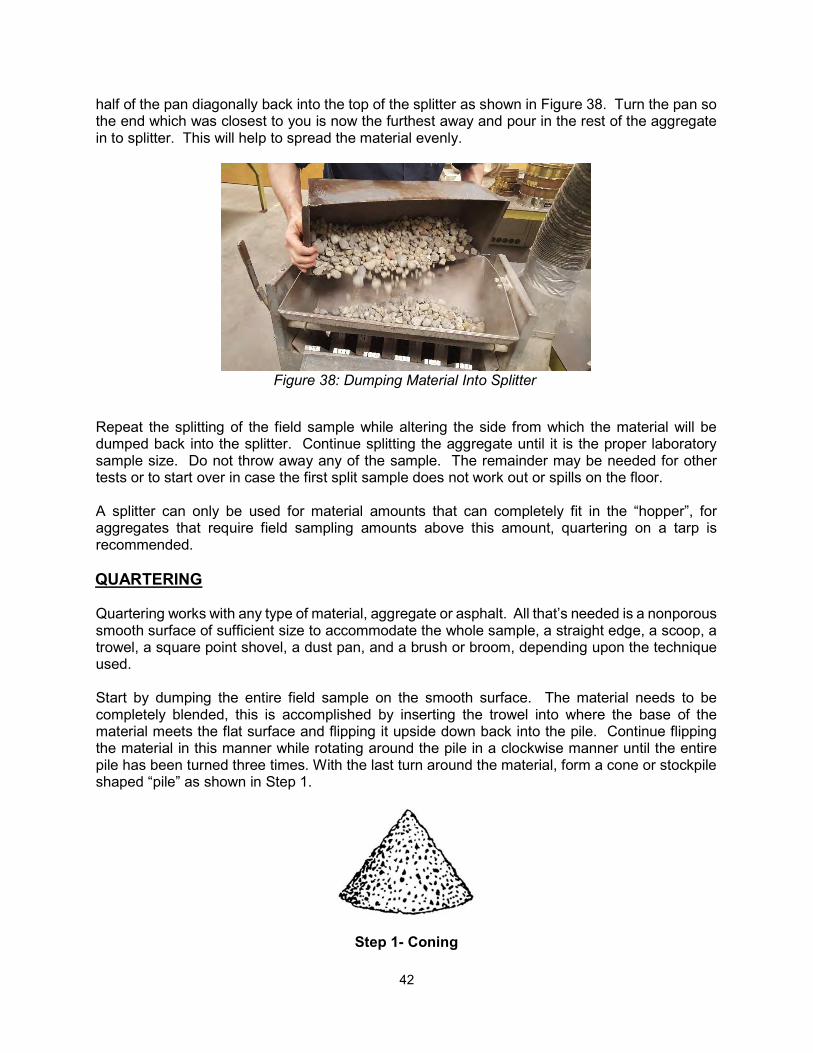
42
half of the pan diagonally back into the top of the splitter as shown in Figure 38. Turn the pan so the end which was closest to you is now the furthest away and pour in the rest of the aggregate in to splitter. This will help to spread the material evenly.
Figure 38: Dumping Material Into Splitter
Repeat the splitting of the field sample while altering the side from which the material will be dumped back into the splitter. Continue splitting the aggregate until it is the proper laboratory sample size. Do not throw away any of the sample. The remainder may be needed for other tests or to start over in case the first split sample does not work out or spills on the floor. A splitter can only be used for material amounts that can completely fit in the “hopper”, for aggregates that require field sampling amounts above this amount, quartering on a tarp is recommended. QUARTERING Quartering works with any type of material, aggregate or asphalt. All that’s needed is a nonporous smooth surface of sufficient size to accommodate the whole sample, a straight edge, a scoop, a trowel, a square point shovel, a dust pan, and a brush or broom, depending upon the technique used. Start by dumping the entire field sample on the smooth surface. The material needs to be completely blended, this is accomplished by inserting the trowel into where the base of the material meets the flat surface and flipping it upside down back into the pile. Continue flipping the material in this manner while rotating around the pile in a clockwise manner until the entire pile has been turned three times. With the last turn around the material, form a cone or stockpile shaped “pile” as shown in Step 1.
Step 1- Coning
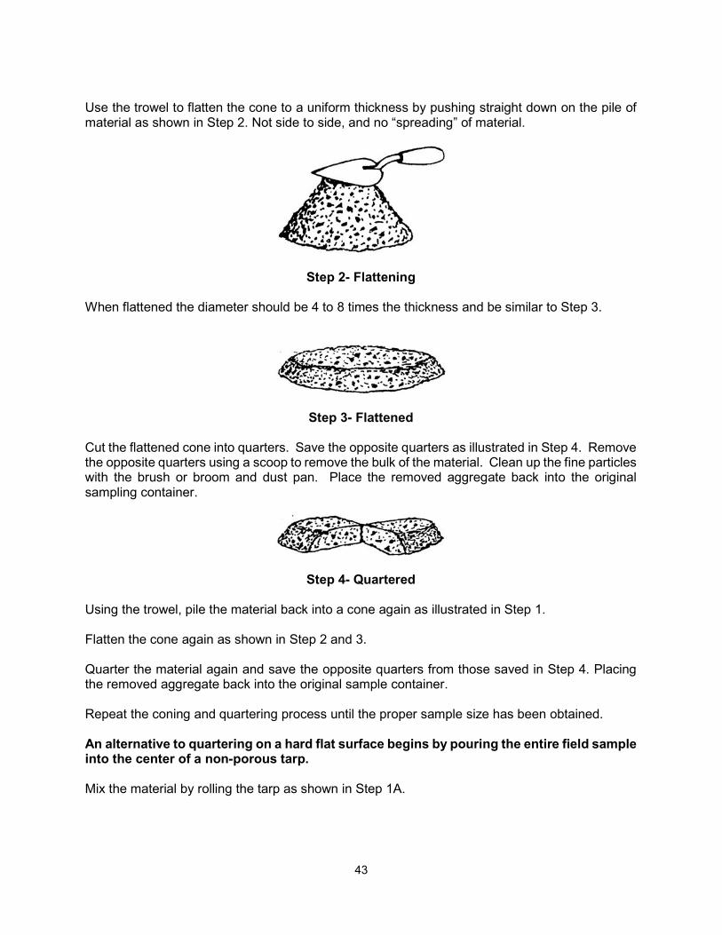
43
Use the trowel to flatten the cone to a uniform thickness by pushing straight down on the pile of material as shown in Step 2. Not side to side, and no “spreading” of material.
Step 2- Flattening When flattened the diameter should be 4 to 8 times the thickness and be similar to Step 3.
Step 3- Flattened Cut the flattened cone into quarters. Save the opposite quarters as illustrated in Step 4. Remove the opposite quarters using a scoop to remove the bulk of the material. Clean up the fine particles with the brush or broom and dust pan. Place the removed aggregate back into the original sampling container.
Step 4- Quartered Using the trowel, pile the material back into a cone again as illustrated in Step 1. Flatten the cone again as shown in Step 2 and 3. Quarter the material again and save the opposite quarters from those saved in Step 4. Placing the removed aggregate back into the original sample container. Repeat the coning and quartering process until the proper sample size has been obtained. An alternative to quartering on a hard flat surface begins by pouring the entire field sample into the center of a non-porous tarp.
Mix the material by rolling the tarp as shown in Step 1A.
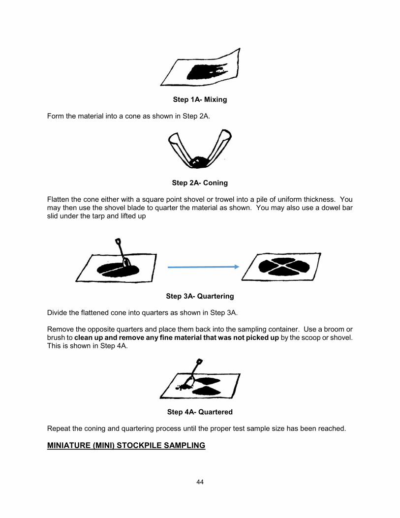
44
Step 1A- Mixing Form the material into a cone as shown in Step 2A.
Step 2A- Coning Flatten the cone either with a square point shovel or trowel into a pile of uniform thickness. You may then use the shovel blade to quarter the material as shown. You may also use a dowel bar slid under the tarp and lifted up
Step 3A- Quartering
Divide the flattened cone into quarters as shown in Step 3A. Remove the opposite quarters and place them back into the sampling container. Use a broom or brush to clean up and remove any fine material that was not picked up by the scoop or shovel. This is shown in Step 4A.
Step 4A- Quartered Repeat the coning and quartering process until the proper test sample size has been reached. MINIATURE (MINI) STOCKPILE SAMPLING
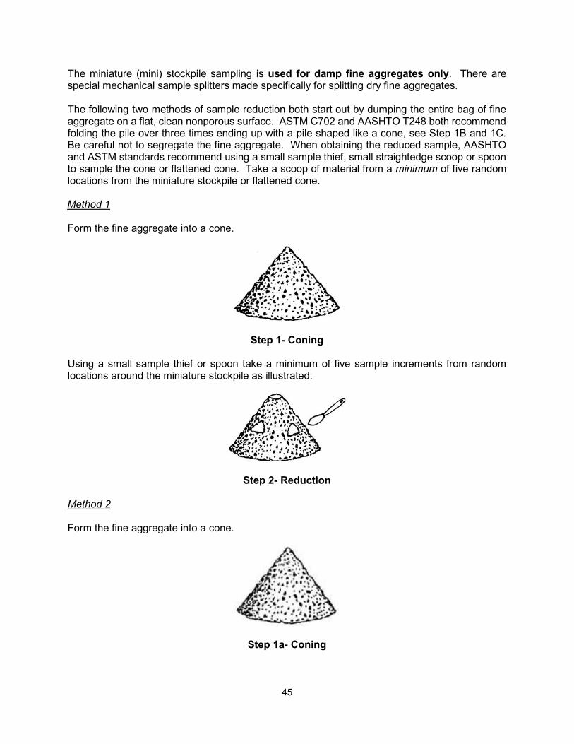
45
The miniature (mini) stockpile sampling is used for damp fine aggregates only. There are special mechanical sample splitters made specifically for splitting dry fine aggregates. The following two methods of sample reduction both start out by dumping the entire bag of fine aggregate on a flat, clean nonporous surface. ASTM C702 and AASHTO T248 both recommend folding the pile over three times ending up with a pile shaped like a cone, see Step 1B and 1C. Be careful not to segregate the fine aggregate. When obtaining the reduced sample, AASHTO and ASTM standards recommend using a small sample thief, small straightedge scoop or spoon to sample the cone or flattened cone. Take a scoop of material from a minimum of five random locations from the miniature stockpile or flattened cone. Method 1 Form the fine aggregate into a cone.
Step 1- Coning Using a small sample thief or spoon take a minimum of five sample increments from random locations around the miniature stockpile as illustrated.
Step 2- Reduction Method 2 Form the fine aggregate into a cone.
Step 1a- Coning
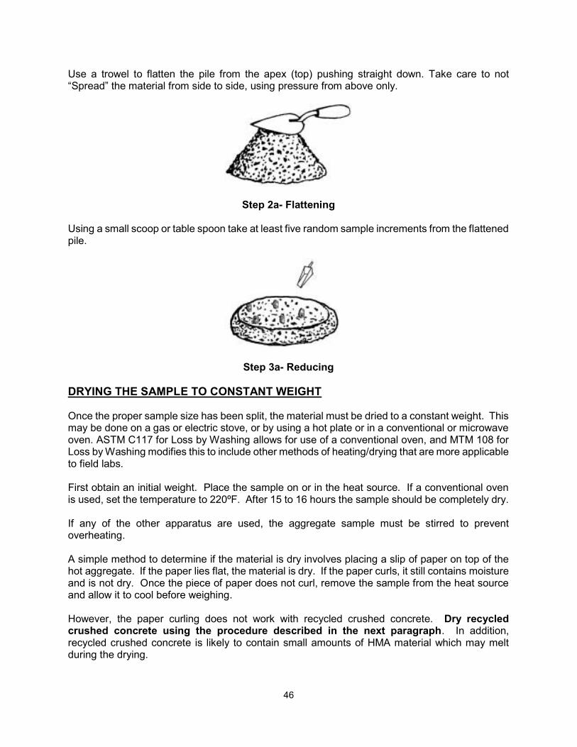
46
Use a trowel to flatten the pile from the apex (top) pushing straight down. Take care to not “Spread” the material from side to side, using pressure from above only.
Step 2a- Flattening Using a small scoop or table spoon take at least five random sample increments from the flattened pile.
Step 3a- Reducing DRYING THE SAMPLE TO CONSTANT WEIGHT Once the proper sample size has been split, the material must be dried to a constant weight. This may be done on a gas or electric stove, or by using a hot plate or in a conventional or microwave oven. ASTM C117 for Loss by Washing allows for use of a conventional oven, and MTM 108 for Loss by Washing modifies this to include other methods of heating/drying that are more applicable to field labs. First obtain an initial weight. Place the sample on or in the heat source. If a conventional oven is used, set the temperature to 220ºF. After 15 to 16 hours the sample should be completely dry. If any of the other apparatus are used, the aggregate sample must be stirred to prevent overheating. A simple method to determine if the material is dry involves placing a slip of paper on top of the hot aggregate. If the paper lies flat, the material is dry. If the paper curls, it still contains moisture and is not dry. Once the piece of paper does not curl, remove the sample from the heat source and allow it to cool before weighing. However, the paper curling does not work with recycled crushed concrete. Dry recycled crushed concrete using the procedure described in the next paragraph. In addition, recycled crushed concrete is likely to contain small amounts of HMA material which may melt during the drying.
47
If the piece of paper is not used, heat the material until it appears dry. Cool the sample until the heat will not damage the scales. Then weigh it and record the mass. Place the material back on or in the heating device. If an oven is used, then wait 20 to 30 minutes. If a hot plate or burner is used, then allow no more than 10 minutes. Even a very low heat setting using a hot plate or burner can quickly overheat the aggregate. Remove the material from the heat source. Let it cool and reweigh the material. For aggregate material that is weighed to the whole gram, such as material gradations from the 902-1 chart in the Standard Specifications for Construction, use the following procedure to measure constant weight.
If the two weighs are within 0.10 percent of each other, the material is considered to have reached constant weight. If the weight difference is greater than 0.10 percent, continue the drying process until two successive weighs are within 0.10 percent.
For aggregate material that is weighed to the tenth of a gram, such as material gradations from the HMA Production Manual use the following procedure to measure constant weight.
According to the HMA Production Manual constant weight is achieved when two successive weights have changed less than 0.3g in 15 mins.

48
49
CHAPTER 5 – THE MECHANICAL ANALYSIS
It is important to learn the correct procedures necessary to perform a sieve analysis, loss by wash, and various particle identifications. Filling out the related test forms completely and accurately is very important. The test results will be used by many people to make important decisions such as the acceptance or rejection of material, determining product use and even settle claim disputes. Errors can be very costly to the product producers and purchasers. A typical Mechanical Analysis Report form is Form 1901. This report can be used with most aggregate specifications. ROUNDING PROCEDURES Government agencies and private industry require the reporting of numerical data in some form such as whole numbers, tenths or hundredths. When performing mathematical calculations, it becomes necessary to round numbers. The American Society for Testing and Materials (ASTM) Standard E29 assures consistent rounding of numbers. ASTM Standard E29 states the following when using the Rounding Method:
1. When the figure next beyond the last place to be retained is less than 5, retain unchanged the figure in the last place retained. (Example: Round to the nearest tenth 3.74 = 3.7).
2. When the figure next beyond the last place to be retained is greater than 5, increase by
1 the figure in the last place retained. (Example: Round to the nearest tenth 7.79 = 7.8).
3. When the figure next beyond the last place to be retained is 5 and there are no figures
beyond this 5, or only zeros, increase by 1 the figure to be retained if it is odd, (Example: Round to the nearest tenth 6.75 = 6.8) leave the figure unchanged if it is even, (Example: Round to the nearest tenth 9.45 = 9.4). Increase by 1 the figure in the last place retained, if there are figures beyond this 5 (Example: Round to the nearest tenth 9.450001 = 9.5).
EXAMPLE PRODUCTION PROBLEM Adam's Asphalt Company has a proposal for road construction. The Job Number is 49307A, Control Number DST 5400, Federal Number STP 0893 (312) and Federal Item Number JH3621. They have contracted with Stay Strong Aggregate, an aggregate producer, to produce
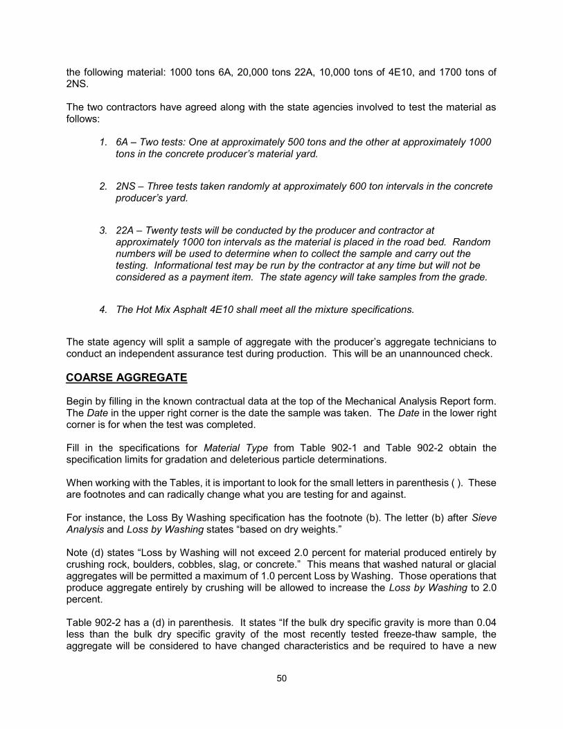
50
the following material: 1000 tons 6A, 20,000 tons 22A, 10,000 tons of 4E10, and 1700 tons of 2NS. The two contractors have agreed along with the state agencies involved to test the material as follows:
1. 6A – Two tests: One at approximately 500 tons and the other at approximately 1000 tons in the concrete producer’s material yard.
2. 2NS – Three tests taken randomly at approximately 600 ton intervals in the concrete
producer’s yard.
3. 22A – Twenty tests will be conducted by the producer and contractor at
approximately 1000 ton intervals as the material is placed in the road bed. Random numbers will be used to determine when to collect the sample and carry out the testing. Informational test may be run by the contractor at any time but will not be considered as a payment item. The state agency will take samples from the grade.
4. The Hot Mix Asphalt 4E10 shall meet all the mixture specifications.
The state agency will split a sample of aggregate with the producer’s aggregate technicians to conduct an independent assurance test during production. This will be an unannounced check. COARSE AGGREGATE Begin by filling in the known contractual data at the top of the Mechanical Analysis Report form. The Date in the upper right corner is the date the sample was taken. The Date in the lower right corner is for when the test was completed. Fill in the specifications for Material Type from Table 902-1 and Table 902-2 obtain the specification limits for gradation and deleterious particle determinations. When working with the Tables, it is important to look for the small letters in parenthesis ( ). These are footnotes and can radically change what you are testing for and against. For instance, the Loss By Washing specification has the footnote (b). The letter (b) after Sieve Analysis and Loss by Washing states “based on dry weights.” Note (d) states “Loss by Washing will not exceed 2.0 percent for material produced entirely by crushing rock, boulders, cobbles, slag, or concrete.” This means that washed natural or glacial aggregates will be permitted a maximum of 1.0 percent Loss by Washing. Those operations that produce aggregate entirely by crushing will be allowed to increase the Loss by Washing to 2.0 percent. Table 902-2 has a (d) in parenthesis. It states “If the bulk dry specific gravity is more than 0.04 less than the bulk dry specific gravity of the most recently tested freeze-thaw sample, the aggregate will be considered to have changed characteristics and be required to have a new
51
freeze-thaw test conducted prior to use on Department projects.” Note (e) states “Clay-Ironstone particles must not exceed 1.0 percent for 6AAA, 6AA and 26A, and 2.0 percent for 6A and 17A. Clay-Ironstone particles are also included in the percentage of soft particles for these aggregates.” Note (g) states "Except for pre-stressed beams, the sum of the soft and chert particles may be up to 3.0 percent higher than the values determined from the sample tested for freeze-thaw durability. However, under no circumstances will the deleterious particle percentages exceed specification limits in Table 902-2. In addition, a source may be restricted to a minimum percent crushed not to exceed 15 percent less than the percent crushed in the freeze-thaw sample. When the freeze-thaw dilation is between 0.040 and 0.067 percent per 100 cycles, more restrictive limits will be applied.” Table 902-2 has requirements for the Los Angeles Abrasion Test and the Freeze-Thaw Dilation Test. These tests are not done as part of the Mechanical Analysis. However, they are briefly described in Chapter 7 titled Other Tests. Table 902-2 has no requirement for crushed material for 6A as indicated by the blank space in the column under Crushed Material, % min. Michigan Test Method 110 specifies which sieves the deleterious material (soft and chert) must be picked. It is recommend to draw a heavy line under the ⅜ inch data entry line. This serves as a memory device to add the ⅜ inch sieve to the nest of sieves during the sieve analysis. It is not a requirement for the gradation analysis. However, the material retained on the ⅜ inch sieve and the larger sieves are saved in a separate pile to be examined (also known as "picked") for deleterious material. A representative sample from the field must be reduced in size as described in Chapter 4- Sample Sizes and Sample Reduction. Using 6A as an example; 100 percent of the material must pass the 1.5 inch sieve. The first sieve that may retain aggregate is the 1 inch sieve. Looking at the chart used by the Michigan Department of Transportation in Chapter 4, Figure 35: MDOT Minimum Laboratory Sample Size; the sample shall weigh a minimum of 3500 grams after splitting. Do not assume the sample is totally dry. Therefore, the sample must be dried after it has been split (reduced to testing weight) to a constant weight. Drying of the sample is described in the last paragraph of Chapter 4. Weigh the sample after it has been dried and cooled. This weight becomes the Initial Weight of Sample recorded on the Mechanical Analysis Report form. LOSS BY WASHING ASTM C117 Standard Test Method for Materials Finer than 75 um (No.200) Sieve in Mineral Aggregates by Washing & MTM 108 Michigan Test Method for Materials Finer than No. 200 Sieve in Mineral Aggregates by Washing. The Loss by Washing (LBW) removes the clay, and silt sized particles from the sample. The following equipment is necessary to wash aggregate:
A pan that’s large enough to hold the aggregate while allowing its agitation without water or aggregate loss.
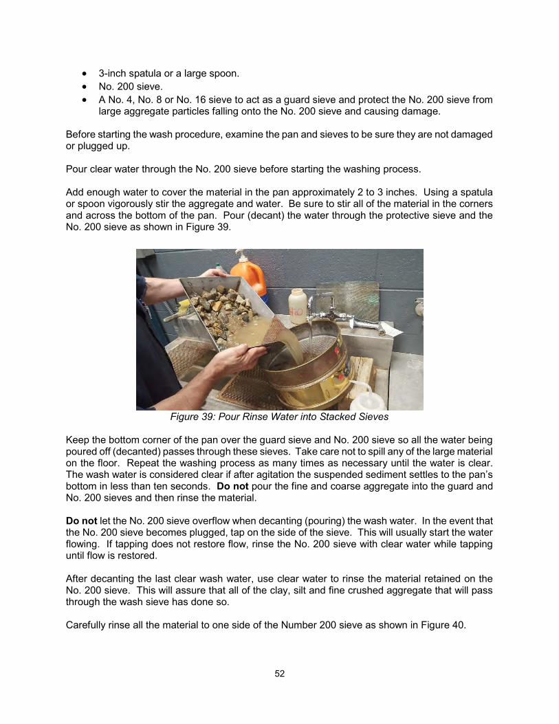
52
3-inch spatula or a large spoon. No. 200 sieve. A No. 4, No. 8 or No. 16 sieve to act as a guard sieve and protect the No. 200 sieve from
large aggregate particles falling onto the No. 200 sieve and causing damage. Before starting the wash procedure, examine the pan and sieves to be sure they are not damaged or plugged up. Pour clear water through the No. 200 sieve before starting the washing process. Add enough water to cover the material in the pan approximately 2 to 3 inches. Using a spatula or spoon vigorously stir the aggregate and water. Be sure to stir all of the material in the corners and across the bottom of the pan. Pour (decant) the water through the protective sieve and the No. 200 sieve as shown in Figure 39.
Figure 39: Pour Rinse Water into Stacked Sieves Keep the bottom corner of the pan over the guard sieve and No. 200 sieve so all the water being poured off (decanted) passes through these sieves. Take care not to spill any of the large material on the floor. Repeat the washing process as many times as necessary until the water is clear. The wash water is considered clear if after agitation the suspended sediment settles to the pan’s bottom in less than ten seconds. Do not pour the fine and coarse aggregate into the guard and No. 200 sieves and then rinse the material. Do not let the No. 200 sieve overflow when decanting (pouring) the wash water. In the event that the No. 200 sieve becomes plugged, tap on the side of the sieve. This will usually start the water flowing. If tapping does not restore flow, rinse the No. 200 sieve with clear water while tapping until flow is restored. After decanting the last clear wash water, use clear water to rinse the material retained on the No. 200 sieve. This will assure that all of the clay, silt and fine crushed aggregate that will pass through the wash sieve has done so. Carefully rinse all the material to one side of the Number 200 sieve as shown in Figure 40.
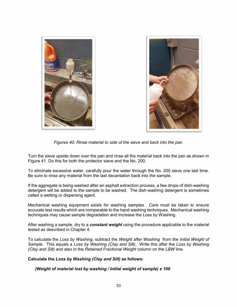
53
Figures 40: Rinse material to side of the sieve and back into the pan
Turn the sieve upside down over the pan and rinse all the material back into the pan as shown in Figure 41. Do this for both the protector sieve and the No. 200. To eliminate excessive water, carefully pour the water through the No. 200 sieve one last time. Be sure to rinse any material from the last decantation back into the sample. If the aggregate is being washed after an asphalt extraction process, a few drops of dish-washing detergent will be added to the sample to be washed. The dish-washing detergent is sometimes called a wetting or dispersing agent. Mechanical washing equipment exists for washing samples. Care must be taken to ensure accurate test results which are comparable to the hand washing techniques. Mechanical washing techniques may cause sample degradation and increase the Loss by Washing. After washing a sample, dry to a constant weight using the procedure applicable to the material tested as described in Chapter 4. To calculate the Loss by Washing, subtract the Weight after Washing from the Initial Weight of Sample. This equals a Loss by Washing (Clay and Silt). Write this after the Loss by Washing (Clay and Silt) and also in the Retained Fractional Weight column on the LBW line. Calculate the Loss by Washing (Clay and Silt) as follows:
(Weight of material lost by washing / Initial weight of sample) x 100
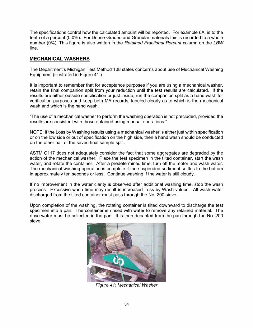
54
The specifications control how the calculated amount will be reported. For example 6A, is to the tenth of a percent (0.0%). For Dense-Graded and Granular materials this is recorded to a whole number (0%). This figure is also written in the Retained Fractional Percent column on the LBW line. MECHANICAL WASHERS The Department’s Michigan Test Method 108 states concerns about use of Mechanical Washing Equipment (illustrated in Figure 41.) It is important to remember that for acceptance purposes if you are using a mechanical washer, retain the final companion split from your reduction until the test results are calculated. If the results are either outside specification or just inside, run the companion split as a hand wash for verification purposes and keep both MA records, labeled clearly as to which is the mechanical wash and which is the hand wash. “The use of a mechanical washer to perform the washing operation is not precluded, provided the results are consistent with those obtained using manual operations.” NOTE: If the Loss by Washing results using a mechanical washer is either just within specification or on the low side or out of specification on the high side, then a hand wash should be conducted on the other half of the saved final sample split. ASTM C117 does not adequately consider the fact that some aggregates are degraded by the action of the mechanical washer. Place the test specimen in the tilted container, start the wash water, and rotate the container. After a predetermined time, turn off the motor and wash water. The mechanical washing operation is complete if the suspended sediment settles to the bottom in approximately ten seconds or less. Continue washing if the water is still cloudy. If no improvement in the water clarity is observed after additional washing time, stop the wash process. Excessive wash time may result in increased Loss by Wash values. All wash water discharged from the tilted container must pass through the No. 200 sieve. Upon completion of the washing, the rotating container is tilted downward to discharge the test specimen into a pan. The container is rinsed with water to remove any retained material. The rinse water must be collected in the pan. It is then decanted from the pan through the No. 200 sieve.
Figure 41: Mechanical Washer
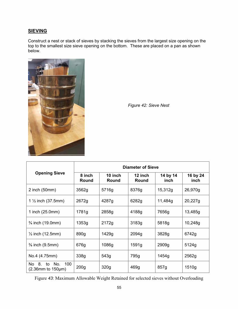
55
SIEVING Construct a nest or stack of sieves by stacking the sieves from the largest size opening on the top to the smallest size sieve opening on the bottom. These are placed on a pan as shown below.
Figure 42: Sieve Nest
Figure 43: Maximum Allowable Weight Retained for selected sieves without Overloading
Opening Sieve
Diameter of Sieve
8 inch Round
10 inch Round
12 inch Round
14 by 14 inch
16 by 24 inch
2 inch (50mm) 3562g 5716g 8376g 15,312g 26,970g
1 ½ inch (37.5mm) 2672g 4287g 6282g 11,484g 20,227g
1 inch (25.0mm) 1781g 2858g 4188g 7656g 13,485g
¾ inch (19.0mm) 1353g 2172g 3183g 5818g 10,248g
½ inch (12.5mm) 890g 1429g 2094g 3828g 6742g
⅜ inch (9.5mm) 676g 1086g 1591g 2909g 5124g
No.4 (4.75mm) 338g 543g 795g 1454g 2562g
No 8. to No. 100 (2.36mm to 150µm) 200g 320g 469g 857g 1510g
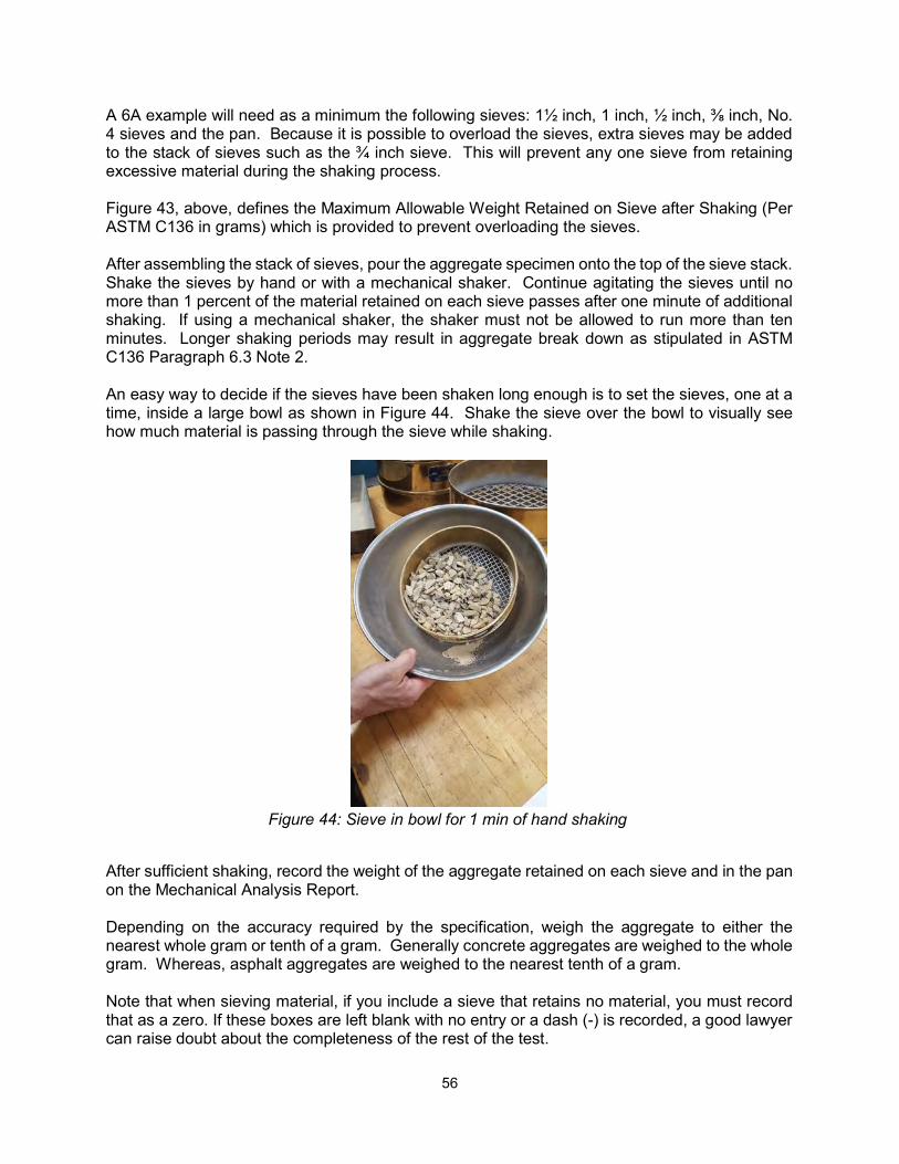
56
A 6A example will need as a minimum the following sieves: 1½ inch, 1 inch, ½ inch, ⅜ inch, No. 4 sieves and the pan. Because it is possible to overload the sieves, extra sieves may be added to the stack of sieves such as the ¾ inch sieve. This will prevent any one sieve from retaining excessive material during the shaking process. Figure 43, above, defines the Maximum Allowable Weight Retained on Sieve after Shaking (Per ASTM C136 in grams) which is provided to prevent overloading the sieves. After assembling the stack of sieves, pour the aggregate specimen onto the top of the sieve stack. Shake the sieves by hand or with a mechanical shaker. Continue agitating the sieves until no more than 1 percent of the material retained on each sieve passes after one minute of additional shaking. If using a mechanical shaker, the shaker must not be allowed to run more than ten minutes. Longer shaking periods may result in aggregate break down as stipulated in ASTM C136 Paragraph 6.3 Note 2. An easy way to decide if the sieves have been shaken long enough is to set the sieves, one at a time, inside a large bowl as shown in Figure 44. Shake the sieve over the bowl to visually see how much material is passing through the sieve while shaking.
Figure 44: Sieve in bowl for 1 min of hand shaking
After sufficient shaking, record the weight of the aggregate retained on each sieve and in the pan on the Mechanical Analysis Report. Depending on the accuracy required by the specification, weigh the aggregate to either the nearest whole gram or tenth of a gram. Generally concrete aggregates are weighed to the whole gram. Whereas, asphalt aggregates are weighed to the nearest tenth of a gram. Note that when sieving material, if you include a sieve that retains no material, you must record that as a zero. If these boxes are left blank with no entry or a dash (-) is recorded, a good lawyer can raise doubt about the completeness of the rest of the test.
57
Total the Retained Fractional Weight column. This should equal the Initial Weight of Sample. During the weighing process, a small amount of material may be misplaced, or due to rounding of numbers, the column may not add to the Initial Weight of Sample. Because of past practices spanning many years, the Department allows an adjustment to the Retained Fractional Weight Total, and the largest numerical weight in the Retained Fractional Weight column. The adjustment will result in the column’s total equaling the Initial Weight of Sample. This adjustment may be a plus or minus number and is called the maximum allowable adjustment. The maximum adjustment allowed is 0.3 of 1 percent as stated in ASTM C136 Paragraph 8.7. If the difference between the initial dry weight and the total retained fractional weight is greater than 0.3 percent, recheck the individual sieve weights and the total weight. If no mathematical error can be found, the sample cannot be used for acceptance purposes. A new split must be obtained if this test was for acceptance. For example a 6A test sample’s Initial Weight of Sample of 3563g multiplied by 0.003 equals 10.689 grams. The maximum permissible adjustment would have to be 10 grams. If the 10.689 grams were rounded to 11 grams, the adjustment would be “more than” the 0.3 of 1 percent permitted. NOTE: The only way to adjust this column is to draw a line through the figure to be corrected and to write in the correct figure. It is not acceptable to erase, blot out figures or to use another means to change the numbers. Complete the Retained Fractional Percent column next. Report the calculations in this column to the nearest tenth. Divide each weight in the Retained Fractional Weight column by the Initial Weight of Sample. This answer is then multiplied by 100 to obtain a percent. After completing the mathematical calculations, total the Retained Fractional Percent column. This total should equal 100.0. When rounding the numbers, the column may add to 99.9 or 100.1. The difference can be adjusted in the column by changing the total to 100.0. Add or subtract the plus or minus adjustment to the largest number in the column, remember in some instances this may be the pan. If the numbers add to 100.2, 100.3, 100.4 or more, or 99.8, 99.7, 99.6 or less, go back and check the column addition. If this doesn’t reveal the error, check the division. If this doesn’t locate the error, add the Retained Fractional Weight column again. An adjustment of more than ±0.1 is uncommon. Complete the Percent Cumulative Retained column next. The numbers in the column are computed with cumulative addition from the top to the bottom of the column. The last column to be calculated is the Percent Cumulative Passing. The calculations are performed by rounding the Percent Cumulative Retained to a whole number. Then subtract the whole number from 100. The Percent Cumulative Passing is recorded as whole numbers except when the aggregate is used in asphalt mixtures or an IAT is being done.
58
Next, compare the numbers in the Percent Cumulative Passing column to the specifications. In the event that a number in the Percent Cumulative Passing column does not meet the specifications, draw a circle around the number out of specification. This quickly calls attention to the problem area. DELETERIOUS PICKS To complete the Mechanical Analysis Report for coarse aggregate, you must do a deleterious pick. This is also detailed in Chapter 6. Basically a deleterious pick involves sorting through the material retained on a specific set of sieves. For the 6A example, the aggregate to be sorted is the material retained on the 1½ inch, 1 inch, ¾ inch, ½ inch and ⅜ inch sieves. This test separates the good aggregate from the bad (deleterious) aggregate. The deleterious aggregates are: friable sandstone, siltstone, shale, ochre, coal, clay-ironstone, structurally weak, material found to be nondurable in service and chert. The deleterious particles are separated into three groups: clay ironstone, other soft and chert. After completing the deleterious pick according to MTM 110, weigh and record the deleterious material picked. The categories picked for coarse aggregate are Soft, Clay Ironstone and Chert. Add the Soft and Clay Ironstone to get the sum for (1) Soft Particles including Clay Ironstone. Sum (1) Soft Particles including Clay Ironstone and (2) Chert together. Record the total of these items on the line Sum of (1) + (2). Next, calculate the pick weight. This is the sum total of the weights recorded in the Retained Fractional Weight column of the sieves included in the sieve stack. To know which sieves are totaled, refer to MTM 110, and mark that sieve and above on your mechanical analysis. It is a good practice to total and label this figure in the remarks space on the mechanical analysis form as well. To calculate the percentage of deleterious particles, divide the weight of the deleterious material picked from the sample by the pick weight. Multiply the answer by 100 and record the answer to the proper significant digit.
% =
ℎ 100
The percentage of deleterious particles is now compared to the specifications. To complete the test, place an “X” in the appropriate box to indicate if the material Meets or Fails, sign the form and clearly print your name. Enter the date the test was completed. Crush percent is calculated as below:
ℎ % =ℎ ℎ
100
59
DENSE-GRADED AGGREGATES Dense-graded aggregates are a uniformly graded blend of coarse, intermediate, fine aggregates, and materials finer than the No. 200 sieve such as clay, silt and fine crushed stone. When produced, these aggregates may achieve high density and stability. They are generally used as base courses, shoulder gravel, on county gravel roads, and as driveway gravel. HMA mixtures are similar to dense-graded aggregates. One difficulty associated with the production of dense-graded aggregates in Michigan is most natural gravel pits contain too much fine aggregate in the minus No. 4 size range. This means the recoverable reserves are reduced if the production set up favors the coarse gradation of the dense graded specification. During processing this will either create the necessity of extracting sand during processing or the blending of stone to compensate. When taken from a pit or quarry, the opposite may be true and sand may have to be added to meet specifications. Occasionally it becomes necessary to blend clay and silt with the aggregates to increase the Loss by Washing. If this is the case, take a small sample of the clay and silt before blending and do a Loss by Wash. Material that appears to be all clay and silt may contain a considerable amount of fine aggregate (sand). This fine aggregate may increase the amount passing the fine sieves such as the No. 8 sieve creating more problems. The mechanical analysis calculations are identical to how they are described in Coarse Aggregate above. What changes is how the results are recorded, some are whole number and some are to a tenth. Always check the specifications to ensure you are recording the results to the proper significant digits. FINE AGGREGATE Fine aggregate (sand) is composed of material finer than the No. 4 sieve and coarser than the No. 200 sieve. The additional footnotes for these products are (b), (c) and (d). Footnote (b) states, “Use test method MTM 108 for Loss by Washing.” Footnote (c) is, “Aggregate having a fineness modulus differing from the base fineness modulus of the source by the amount exceeding the maximum variation specified in the table, will be rejected.” Footnote (d) states, “The base fineness modulus will be supplied by the aggregate producer at the start of each construction season and be within the range of 2.50 - 3.35. The base fineness modulus (FM) including the permissible variation, will be within the 2.50 - 3.35 range.” The Loss by Washing, sieve analysis, and mathematical calculations are the same as the other materials. Calculate the fineness modulus by adding the figures in the Percent Cumulative Retained column from the ⅜ inch sieve down to and including the No. 100 sieve. Divide this figure by 100 and report to the second decimal place. To establish a base fineness modulus (FM), run ten mechanical analysis tests (ASTM C33). Add the calculated fineness modulus from each test together and then take an average. This average may be determined at the beginning of the year, or, in some instances, before beginning a specific project. Unlike the asphalt industry, the concrete industry uses FM as a parameter for mix development.
60
The base FM for the 2NS must be within the range of 2.50 to 3.35 for the aggregate to be accepted. After establishing the base FM, a tolerance is applied, such as the ±0.20 for the 2NS. This reduces the production range and increases the aggregate’s uniformity. Note: Neither the 2FA nor 3FA require the calculation of the fineness modulus. The fineness modulus measures the material’s grain size. The 2.50 suggests a fine material whereas the 3.35 suggests a coarser material. When a fineness modulus is required as part of the testing procedure, be sure to add all of the sieves from the ⅜ inch sieve down to and including the No. 100 sieve to the stack of sieves used for sieving. For example, the 2MS aggregate does not require the No. 16 and the No. 30 sieves to do a sieve analysis, but they are required to calculate the fineness modulus. ORGANIC PLATE NUMBER The right column of the Mechanical Analysis Report form has a line called the Organic Plate Number. This line in indicates a colorimetric test result. This was determined by comparing the results of soaking sand in a 3 percent solution of sodium hydroxide for 24 hours then comparing the color of the solution to a glass or plastic color reference chart. The chart colors are numbered from one to five. The number's one, two or three are within acceptable limits. Test results four and five indicate the aggregate shall be “tentatively rejected pending further testing.” This is described in more detail in Chapter 7. If the sand is to be used in Portland Cement Concrete and it is tentatively rejected, further testing on the fine aggregate must be done. This involves making Portland Cement Concrete cubes and testing them for strength. RUBBLE CHECK FOR CRUSHED CONCRETE AGGREGATE
In addition to gradation testing for crushed concrete, you must do a rubble check. This ensures that the material does not include material detrimental to its use. Rubble in crushed concrete includes the following particles: building brick, wood, plaster or any particle with HMA coating. This pick would be on the same size fraction and sieves specified for deleterious particles in MTM 110, but is calculated by particle count as below:
% =# #
100
MDOT Standard Specifications for Construction 902.05 specifies a maximum of 5% rubble by particle count for Dense-Graded aggregates for Base Course, Surface Course, Shoulders, Approaches and Patching. MDOT 12SP-303A-02 specifies a maximum of 5.0% rubble by particle count for 4G Open-Graded Drainage Course.
61
THE AGGREGATE INSPECTION DAILY REPORT The Aggregate Inspection Daily Report Form 1900 is used as a summary of the daily testing activities. The technician must submit it daily. The form is filled out from the information on the Mechanical Analysis Report. The Aggregate Inspection Daily Report is to be filled out completely and accurately. In addition to the information found at the top of the Mechanical Analysis Report, the following information is also required on the form:
1. The name of the Project Engineer. 2. The name of the prime contractor for the project. 3. The pit/quarry name (Pit and quarries are named after many things such as people,
companies, cities, towns, roads geographic locations or landmarks.). 4. Where the material is produced. 5. The MDOT Aggregate Source Inventory (ASI) pit number. The pit numbers always start
with two numbers that indicate the county or state where the pit/quarry is located. (Our example is number 54, which is Mecosta County.) The next numbers are the registration number of the pit or quarry. Having these numbers will enable the user of the information to go to the “Aggregate Source Inventory” published on the web and available from the Department’s external website. This book contains aggregate sources, selected test results and driving directions to get to the pit/ quarries.
All results required by the specifications are to be reported on the form. The specifications for the material being tested are to be written in the boxes under the Specification Requirements. Also, if specifications are indicated for Crushed Material, Clay Ironstone, Soft Particles Including Clay Ironstone or Chert, place these above the boxes that will contain the test data. When the test data is recorded, transfer the Cumulative Percent Passing and the percent of crushed and deleterious material as appropriate from the Mechanical Analysis Report (do not transfer weights.) For aggregates, which require a determination of deleterious particles (commonly known as a “pick”), an entry must be made under each item designated by the specifications. For example, if there is a specification limit of chert content for the aggregate being tested and no chert is found in the test sample, the figure 0.0 must be recorded. If such a space on the form is left blank, or if a dash (-) is recorded, it is inferred that no check for that item was made. General information is to be given as shown on the sample report. Carry the test numbers independently for each project, and continue the number sequence to the end of the project. Give the source from which the aggregate was sampled and if the shipment is by rail, include the car initials and number of each car. Do not record a Test Number for materials visually inspected. Report the quantities represented as accurately as possible, breaking them down into sub-totals. Be sure to make a note on the form if a Special Provision, Supplemental Specification or Modification to the material exists in the contract documents. The Aggregate Inspection Daily Report is to be filled out each day production is in progress for a project. Note processing changes in the Remarks such as changing wire cloth sizes that will affect test results or plants not producing for a day due to rain. The Mechanical Analysis Reports are retained by the technician at the field inspection quarters and are to be available for review by supervisory personnel. When independent assurance
62
samples are submitted to the Region or Construction Field Services Division, a copy of the technician’s Mechanical Analysis Report must accompany the sample. The Aggregate Inspection Daily Report must be sent to the project folder for retention. Unless other instructions are given, separate Aggregate Inspection Daily Reports are to be prepared for each project or purchase order. If concrete aggregates (coarse and/or fine), open graded and dense graded aggregates are shipped to the same project from the same source, separate Aggregate Inspection Daily Reports are required for each type of aggregate. The copy of the Aggregate Inspection Daily Report on aggregates supplied to fulfill Maintenance purchase orders, which would normally be sent to the Project Engineer, should be sent to the Region Maintenance Engineer receiving the aggregate shipment. All aggregate rejected by the technician must be reported and its disposition noted even if the quantity is small. Circle the specific result or results which failed to meet the specification requirements. In cases where the aggregates are rejected on visual inspection, the reason for the rejection is to be stated on the report. All rejections shall be reported on a separate Aggregate Inspection Daily Report. HOT MIX ASPHALT The form used for testing of HMA is dependent on the material tested. Make sure to check the MDOT forms repository for the most current form needed. The aggregate sieve analysis on these forms are all calculated in the same way. Begin by filling in the known contractual information at the top of the form. The specifications for aggregates used in HMA mixtures are found in Special Provision documents published by the Department. The technician must understand the designations used for the various mixtures. An example is the designation 4E10. Each part of the designation has a meaning to the technicians who work with Hot Mix Asphalt. The number four indicates the gradation requirements the mixture must meet. This is found in the relevant specification. Note that all the sieves are used to determine the gradation through Mechanical Analysis, but not all sieves have gradation requirements. The next part of the designation is the letter E. The E indicates the number of Equivalent Single Axle Load’s (ESAL’s) projected over a 20-year period. For design purposes, an ESAL carries a load of 18,000 pounds and has four tires. The last figure in the example is the number “10”. This indicates that the HMA mixture is expected to withstand ten million equivalent single axle loads (ESAL’s) over a 20-year period. The mix type designations range from a mix type E03 which indicates 300,000 ESAL’s to an E50 which indicates 50,000,000 ESAL’s over a 20-year period. The aggregates for Hot Mix Asphalt are processed and stockpiled in fractional sizes such as 1/2 to 5/16 inch and 5/16 inch minus.
63
The technician will perform gradations on these stockpiles for information to use in blending for a specific asphalt mix design. Once a mix design has been completed and approved for use, a Job Mix Formula will be prepared for the field application of the design. The gradations will then be stated as target values. The asphalt plants have several cold feed bins that supply proportionally the materials into the asphalt plant. This is how the plant operators maintain a uniform blend of the aggregates. At a location after the last cold feed bin has emptied onto the belt but before the combined aggregate is fed into the plant, a sample is taken to determine if the blended aggregates meet the gradation requirements of the mixture. After the mixture is made, samples of the Hot Mix Asphalt are taken. The asphalt is removed either by a chemical extraction process or ignition furnace, which burns the asphalt from the mix. The gradations are then checked for Quality Control/Quality Assurance purposes. At this point, a tolerance is applied to the total percent passing of some of or all of the sieve’s specifications listed on the Job Mix Formula. For example, the No. 8 sieve may have a tolerance of ±5.00 percent and the material passing the No. 200 sieve may have a tolerance of ±1.70 percent depending upon contract requirements. The aggregate would then have an upper and lower specification limit. If the target for the Cumulative Fraction Passing Percent the No. 8 sieve was 35.86 then the upper and lower limit using the ±5.00 percent would become as follows:
35.86 - 5.00 = 30.86 lower limit 35.86 + 5.00 = 40.86 upper limit
From this point on, all the aggregate in the mixture would have to fall within the new established range. NOTE: All weights are to the tenth (0.0). The calculations in the Fraction Retained Percent and the Cumulative Fraction Passing Percent columns are to the nearest tenth (0.0) for Local agency contracts. The calculations for the Fraction Retained, Percent and the Cumulative Fraction Passing, Percent columns for MDOT Quality Control/Quality Assurance projects are carried out to hundredths (0.00). The answer as to how far to carry out the calculations is found in the Special Provisions of project contracts. The sample is dried to a constant weight, the weight recorded, washed, re-dried, weighed again and recorded to determine the Loss by Wash. The material is dumped into a stack of sieves and shaken using the same rules as discussed earlier. A significant difference is the addition of the No. 200 sieve to the stack of sieves when shaking. A small amount of material will pass through the sieve when shaking and be retained in the pan. This is sometimes called Wt. Passing No. 200 (75 µm) By Shaking, but may be have a different designation dependent on the worksheet you use. This weight is added to the Wt. Loss By Washing to obtain the Total Passing No. 200. Calculate the Fraction Retained Percent by dividing the Weight Retained, g by the WT of Dry Aggregate and multiplying by 100. Calculate the Cumulative Fraction Passing, % by taking the Fraction Retained Percent and for the first entry subtracting it from 100. For the second and remainder of entries, take the value
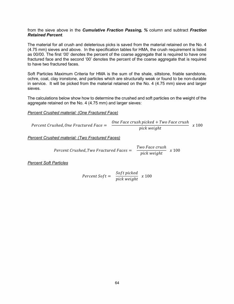
64
from the sieve above in the Cumulative Fraction Passing, % column and subtract Fraction Retained Percent. The material for all crush and deleterious picks is saved from the material retained on the No. 4 (4.75 mm) sieves and above. In the specification tables for HMA, the crush requirement is listed as 00/00. The first ‘00’ denotes the percent of the coarse aggregate that is required to have one fractured face and the second ‘00’ denotes the percent of the coarse aggregate that is required to have two fractured faces. Soft Particles Maximum Criteria for HMA is the sum of the shale, siltstone, friable sandstone, ochre, coal, clay ironstone, and particles which are structurally weak or found to be non-durable in service. It will be picked from the material retained on the No. 4 (4.75 mm) sieve and larger sieves. The calculations below show how to determine the crushed and soft particles on the weight of the aggregate retained on the No. 4 (4.75 mm) and larger sieves: Percent Crushed material: (One Fractured Face)
ℎ , = ℎ + ℎ
ℎ 100
Percent Crushed material: (Two Fractured Faces)
ℎ , = ℎ
ℎ 100
Percent Soft Particles
= ℎ
100
65
CHAPTER 6 – PICKING CRUSHED AND DELETERIOUS MATERIAL
Picking crushed and deleterious particles is done by visual inspection. The specification requirements may require a crush pick, a deleterious pick or picking both crush and deleterious. When picking the crushed or deleterious material, be sure to examine each piece. You may have to pick up some particles and roll them to observe all sides in order for you to accurately identify the particle. Before starting the pick, examine the specifications so you know what to pick and determine which sieves need to be included in the mechanical analysis. All asphalt aggregates use the material retained on all sieves down to and including the No. 4 sieve for picking crushed and deleterious particles. Generally aggregates used in Portland cement concrete and dense graded aggregates used for base courses, surface courses, shoulders and approaches are picked from all sieves retaining aggregate down to and including the ⅜ inch sieve. CRUSHED PARTICLES A crushed particle is a particle having at least one fractured face. Some specifications may require the aggregate have two or more fractured faces. A fractured face may be defined as an aggregate having a surface broken by a mechanical device constituting an area equal to or greater than 50 percent of the projected face as viewed perpendicular to the fractured face. Natural aggregate, to be accepted as crushed must have fractures similar to those produced by mechanical devices. All sandstone particles are considered as crushed particles. Crag, which looks like small stones cemented together naturally, will be considered crushed as long as the largest rock fragment is less than 50 percent of the total aggregate particle. These particles are considered crushed due to the angular nature of the sand grains or adhering concrete matrix. To pick crushed material, inspect and separate the aggregate into piles. Separate the crushed from the uncrushed aggregate and place in separate piles using the criteria of one or more fractured faces, or two or more fractured faces according to the specifications. Calculations are shown on Page 62. DELETERIOUS AND OBJECTIONABLE PARTICLES Deleterious means having a harmful effect. When deleterious particles are exposed to weathering, such as freezing and thawing, they weaken the product in which they are used. Objectionable particles and particles found to be nondurable in service include aggregate particles which have harmful effects on the product in which they are used and are not covered by the list of deleterious particles. An example would be silty limestone which retains internal moisture through the HMA plant and prevents bonding of the asphalt. In addition, things such as large balls of clay or wood particles would also be classified as objectionable.
66
Read the specifications and Special Provisions before picking the deleterious and objectionable particles. At the present time, all types of deleterious particles are picked for Portland cement concrete. Be sure to check the Special Provisions for deleterious picks for Hot Mix Asphalt. Before picking deleterious particles, rinse the material with clear water. This will remove any undesirable coatings on the aggregate and help in the visual inspection. It is hard to determine an aggregate’s type or texture when it’s covered with a thin film of clay or silt. Picking deleterious particles is performed while the particles are wet. It is handy to have a water bottle or cup of water near to moisten particles that may become air dry. Another handy tool is the rat tail file. It is used to check the hardness of the particles. A hammer, steel block, safety ring and safety glasses will be required to break deleterious particles in question. Sometimes, looking at the exterior may not provide enough information as to the material’s identity. If it is necessary to break a particle, put on the safety glasses then place the rock on the steel block and place the safety ring around the rock. Give the rock a quick sharp blow. Examine the fresh fractured face. DELETERIOUS PARTICLES Many years ago, a gentleman named Friedrich Mohs developed a scale to determine the mineral hardness. He designated number one as the softest mineral and number ten as the hardest mineral. His ten reference minerals are:
1. Talc 2. Gypsum 3. Calcite 4. Fluorite 5. Apatite 6. Orthoclase 7. Quartz 8. Topaz 9. Corundum 10. Diamond
As a comparison, dolomite has a hardness of 3½ to 4, Pyrite (fool’s gold) a hardness of 6 to 6½, basalt (diabase) and chert 7. A copper penny has a value of 2½, a pocket knife 5 to 5½, window glass has 5½ to 6, and the rat tail file has a hardness of 6 to 6½. Chert – Chert occurs in many aggregate sources and in a variety of colors. It also can vary in appearance from a dull to a vitreous (glassy) luster and in porosity from porous to dense. All chert is very hard with the exception of chalky chert. The size of chert’s porosity makes it undesirable in Portland concrete cement. Chert has very small microscopic holes which hold water. When the water freezes it expands and physically expands the chert particle. This expansion is not elastic and leaves slightly larger pores available to hold more water during the next freeze cycle. Repeated cycles will eventually create enough strain to break the rock particle and surrounding Portland cement concrete.
67
You may see chert particles in the following forms:
1. White, light gray to tan. These particles are generally light colored, porous, dull and, in general, have a low specific gravity. Chalky chert fits into this classification.
2. Mottled chert can be any combination of white, gray, black, tan or brown. There is
no pattern to the color variation. One way to easily remember is to think of a herd of Holstein cows. No two have the exact same color markings. The porosity within these particles can vary greatly.
3. Vitreous (Glassy) Lustrous chert is generally a gray to black color. The particles
look like broken glass and generally have a higher specific gravity and are darker in color. These also produce very sharp edges.
Physical characteristics to look for:
Chert will generally break with a conchoidal fracture (concave or dish shape).
A file may be used to mark the surface. Firmly pressing the file and drawing a solid line may indicate the aggregate is chert. Some other aggregates will be harder than the file, such as quartz, basalt and hard clay-ironstone centers.
Chert will scratch glass.
The surface will feel smooth if scratched with a fingernail.
If in doubt, break the particle.
If part of an aggregate particle is chert, then the whole aggregate is considered to be chert. This is often referred to as a nodule of chert. More information can be found in MTM 110. The following aggregates are all considered soft materials. When picking, they are kept separate from the chert. Friable Sandstone – Friable sandstone is distinguishable because individual sand grains may be easily abraded by rubbing the particle between the thumb and finger. This is because the individual sand grains are loosely cemented together. The grains in good, or non-friable, sandstones will not rub off. Siltstone – These soft and very porous cemented silt particles range in color from white to a yellow-brown or tan in color. They have a powdery feel when dry and a slippery feel when wet. When dry, they quickly absorb water. They are softer than the file. Shale – Shale particles vary from dark gray to black. They are generally soft, laminated in layers, and have an earthy texture. Some physical characteristics which aid in the identification are:
When damp, most shale will mark greenish-black to black on a canvas bag.
68
If rubbed with the end of a file, shale feels smooth. The mark on the surface will have a waxy appearance like writing with wax, crayon or grease pencil. You will not feel grains.
When scratched with a file, the groove left by the file will be a brownish black color.
When wet, shale generally has a dull appearance, compared to the other aggregates.
Coal – A natural dark-brown to black color, coal’s surface appearance ranges from dull to shiny. Coal can be from moderately soft to brittle and may have a laminated structure. If rubbed with the end of a file, the scratch will also have a waxy appearance. Structurally Weak – These particles have a mixture of light and dark minerals. They can be either white and black or pink and black. They may be readily broken apart by the fingers of one hand. Ochre – Ochre particles have an earthy texture, are extremely soft, porous, and vary from yellowish to brown and red in color. They leave a very distinct color streaks when rubbed on paper or hands. Clay-Ironstone – Clay-ironstone has a separate specification limit. Make sure to check Table the relevant specification for the limit applied to the class of aggregate being tested. Clay Ironstone is a siderite concretion derived from various shale formations. These particles are softer than the file, porous and can range from a yellowish-brown to dark brown, almost black in color. They are present in aggregates in the following four forms. Shells – This is the relatively thin exterior cover that encases the center of the siderite formation. They generally have a smooth exterior and rough interior. Thicker particles often display a laminated structure. Centers – These particles form the irregularly shaped central portion of some siderite concretions. Some have hard exterior surfaces, while others have a thin, very soft, clay type surface covering a hard, dense center. If the center is impure or a stone center, the fragment may be as hard as a file. These particles are generally buff to brown on the surface with a dark gray to black interior. The surface will scratch brown while the interior will scratch white. In addition, the interior of a stone center will not have crystal grains. Fossiliferous – These particles contain traces of fossil shells. Some particles are composed almost entirely of shell fragments. Massive – These particles are generally structure-less or may be very finely laminated. WARNING: Some sandstone will contain iron. It will leave a brown color when rubbed on a cloth or hands, but it also leaves sand grains. This is sandstone.
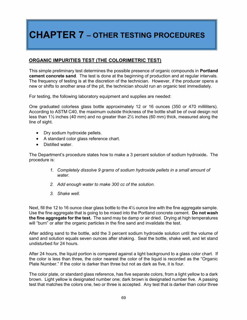
69
CHAPTER 7 – OTHER TESTING PROCEDURES ORGANIC IMPURITIES TEST (THE COLORIMETRIC TEST)
This simple preliminary test determines the possible presence of organic compounds in Portland cement concrete sand. The test is done at the beginning of production and at regular intervals. The frequency of testing is at the discretion of the technician. However, if the producer opens a new or shifts to another area of the pit, the technician should run an organic test immediately. For testing, the following laboratory equipment and supplies are needed: One graduated colorless glass bottle approximately 12 or 16 ounces (350 or 470 milliliters). According to ASTM C40, the maximum outside thickness of the bottle shall be of oval design not less than 1½ inches (40 mm) and no greater than 2½ inches (60 mm) thick, measured along the line of sight.
Dry sodium hydroxide pellets. A standard color glass reference chart. Distilled water.
The Department’s procedure states how to make a 3 percent solution of sodium hydroxide. The procedure is:
1. Completely dissolve 9 grams of sodium hydroxide pellets in a small amount of
water.
2. Add enough water to make 300 cc of the solution.
3. Shake well.
Next, fill the 12 to 16 ounce clear glass bottle to the 4½ ounce line with the fine aggregate sample. Use the fine aggregate that is going to be mixed into the Portland concrete cement. Do not wash the fine aggregate for the test. The sand may be damp or air dried. Drying at high temperatures will “burn” or alter the organic particles in the fine sand and invalidate the test. After adding sand to the bottle, add the 3 percent sodium hydroxide solution until the volume of sand and solution equals seven ounces after shaking. Seal the bottle, shake well, and let stand undisturbed for 24 hours. After 24 hours, the liquid portion is compared against a light background to a glass color chart. If the color is less than three, the color nearest the color of the liquid is recorded as the “Organic Plate Number.” If the color is darker than three but not as dark as five, it is four. The color plate, or standard glass reference, has five separate colors, from a light yellow to a dark brown. Light yellow is designated number one; dark brown is designated number five. A passing test that matches the colors one, two or three is accepted. Any test that is darker than color three
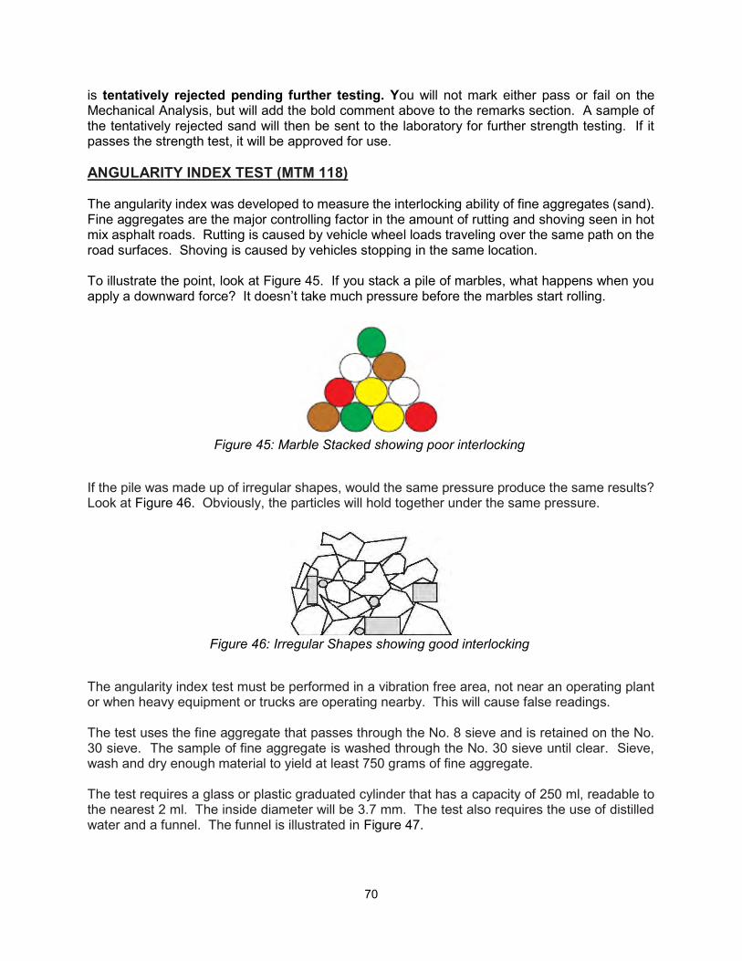
70
is tentatively rejected pending further testing. You will not mark either pass or fail on the Mechanical Analysis, but will add the bold comment above to the remarks section. A sample of the tentatively rejected sand will then be sent to the laboratory for further strength testing. If it passes the strength test, it will be approved for use. ANGULARITY INDEX TEST (MTM 118) The angularity index was developed to measure the interlocking ability of fine aggregates (sand). Fine aggregates are the major controlling factor in the amount of rutting and shoving seen in hot mix asphalt roads. Rutting is caused by vehicle wheel loads traveling over the same path on the road surfaces. Shoving is caused by vehicles stopping in the same location. To illustrate the point, look at Figure 45. If you stack a pile of marbles, what happens when you apply a downward force? It doesn’t take much pressure before the marbles start rolling.
Figure 45: Marble Stacked showing poor interlocking
If the pile was made up of irregular shapes, would the same pressure produce the same results? Look at Figure 46. Obviously, the particles will hold together under the same pressure.
Figure 46: Irregular Shapes showing good interlocking
The angularity index test must be performed in a vibration free area, not near an operating plant or when heavy equipment or trucks are operating nearby. This will cause false readings. The test uses the fine aggregate that passes through the No. 8 sieve and is retained on the No. 30 sieve. The sample of fine aggregate is washed through the No. 30 sieve until clear. Sieve, wash and dry enough material to yield at least 750 grams of fine aggregate. The test requires a glass or plastic graduated cylinder that has a capacity of 250 ml, readable to the nearest 2 ml. The inside diameter will be 3.7 mm. The test also requires the use of distilled water and a funnel. The funnel is illustrated in Figure 47.
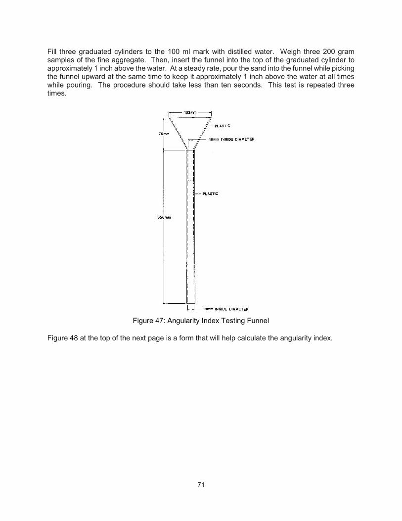
71
Fill three graduated cylinders to the 100 ml mark with distilled water. Weigh three 200 gram samples of the fine aggregate. Then, insert the funnel into the top of the graduated cylinder to approximately 1 inch above the water. At a steady rate, pour the sand into the funnel while picking the funnel upward at the same time to keep it approximately 1 inch above the water at all times while pouring. The procedure should take less than ten seconds. This test is repeated three times.
Figure 47: Angularity Index Testing Funnel
Figure 48 at the top of the next page is a form that will help calculate the angularity index.
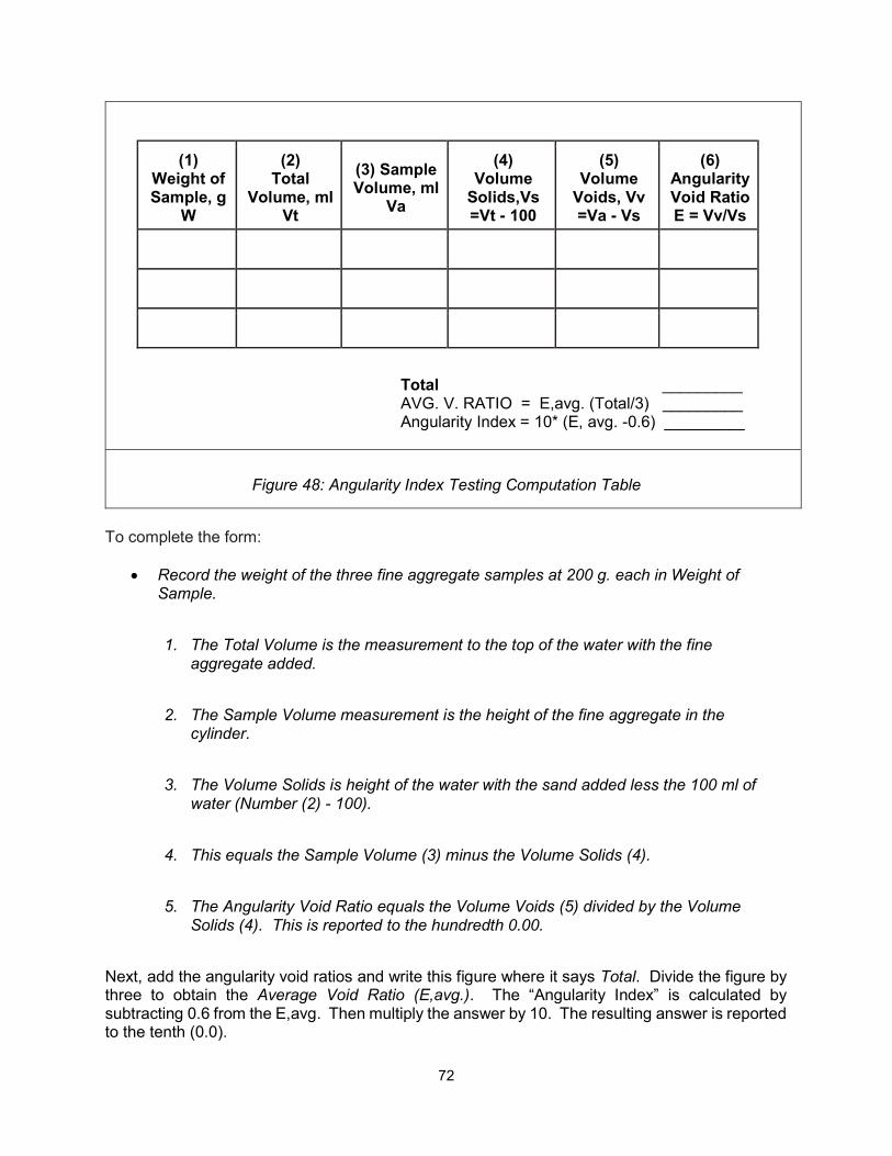
72
To complete the form:
Record the weight of the three fine aggregate samples at 200 g. each in Weight of Sample.
1. The Total Volume is the measurement to the top of the water with the fine
aggregate added.
2. The Sample Volume measurement is the height of the fine aggregate in the
cylinder.
3. The Volume Solids is height of the water with the sand added less the 100 ml of
water (Number (2) - 100).
4. This equals the Sample Volume (3) minus the Volume Solids (4).
5. The Angularity Void Ratio equals the Volume Voids (5) divided by the Volume
Solids (4). This is reported to the hundredth 0.00.
Next, add the angularity void ratios and write this figure where it says Total. Divide the figure by three to obtain the Average Void Ratio (E,avg.). The “Angularity Index” is calculated by subtracting 0.6 from the E,avg. Then multiply the answer by 10. The resulting answer is reported to the tenth (0.0).
(1) Weight of Sample, g
W
(2) Total
Volume, ml Vt
(3) Sample Volume, ml
Va
(4) Volume
Solids,Vs =Vt - 100
(5) Volume
Voids, Vv =Va - Vs
(6) Angularity Void Ratio E = Vv/Vs
Total _________ AVG. V. RATIO = E,avg. (Total/3) _________ Angularity Index = 10* (E, avg. -0.6) _________
Figure 48: Angularity Index Testing Computation Table
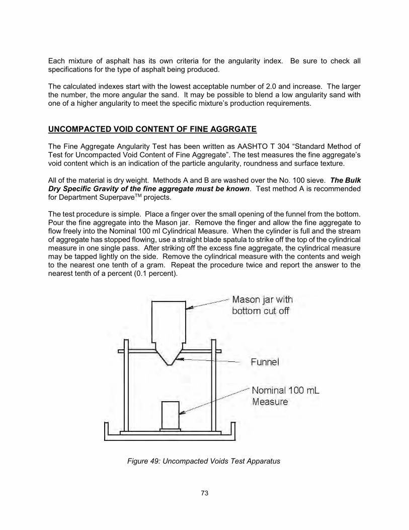
73
Each mixture of asphalt has its own criteria for the angularity index. Be sure to check all specifications for the type of asphalt being produced. The calculated indexes start with the lowest acceptable number of 2.0 and increase. The larger the number, the more angular the sand. It may be possible to blend a low angularity sand with one of a higher angularity to meet the specific mixture’s production requirements. UNCOMPACTED VOID CONTENT OF FINE AGGRGATE The Fine Aggregate Angularity Test has been written as AASHTO T 304 “Standard Method of Test for Uncompacted Void Content of Fine Aggregate”. The test measures the fine aggregate’s void content which is an indication of the particle angularity, roundness and surface texture. All of the material is dry weight. Methods A and B are washed over the No. 100 sieve. The Bulk Dry Specific Gravity of the fine aggregate must be known. Test method A is recommended for Department SuperpaveTM projects. The test procedure is simple. Place a finger over the small opening of the funnel from the bottom. Pour the fine aggregate into the Mason jar. Remove the finger and allow the fine aggregate to flow freely into the Nominal 100 ml Cylindrical Measure. When the cylinder is full and the stream of aggregate has stopped flowing, use a straight blade spatula to strike off the top of the cylindrical measure in one single pass. After striking off the excess fine aggregate, the cylindrical measure may be tapped lightly on the side. Remove the cylindrical measure with the contents and weigh to the nearest one tenth of a gram. Repeat the procedure twice and report the answer to the nearest tenth of a percent (0.1 percent).
Figure 49: Uncompacted Voids Test Apparatus
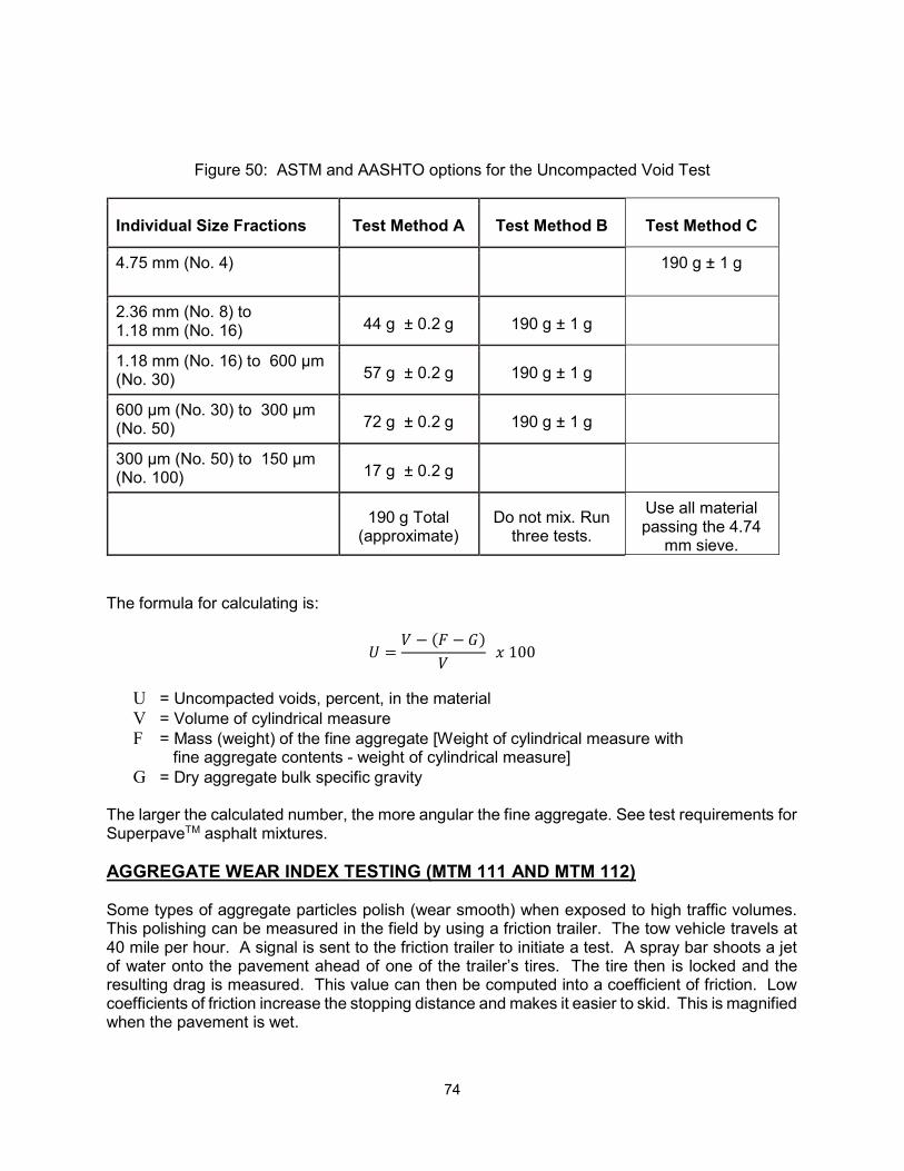
74
The formula for calculating is:
=− −
100
U = Uncompacted voids, percent, in the material V = Volume of cylindrical measure F = Mass (weight) of the fine aggregate [Weight of cylindrical measure with
fine aggregate contents - weight of cylindrical measure] G = Dry aggregate bulk specific gravity
The larger the calculated number, the more angular the fine aggregate. See test requirements for SuperpaveTM asphalt mixtures. AGGREGATE WEAR INDEX TESTING (MTM 111 AND MTM 112) Some types of aggregate particles polish (wear smooth) when exposed to high traffic volumes. This polishing can be measured in the field by using a friction trailer. The tow vehicle travels at 40 mile per hour. A signal is sent to the friction trailer to initiate a test. A spray bar shoots a jet of water onto the pavement ahead of one of the trailer’s tires. The tire then is locked and the resulting drag is measured. This value can then be computed into a coefficient of friction. Low coefficients of friction increase the stopping distance and makes it easier to skid. This is magnified when the pavement is wet.
Figure 50: ASTM and AASHTO options for the Uncompacted Void Test
Individual Size Fractions Test Method A Test Method B Test Method C
4.75 mm (No. 4) 190 g ± 1 g
2.36 mm (No. 8) to 1.18 mm (No. 16) 44 g ± 0.2 g 190 g ± 1 g
1.18 mm (No. 16) to 600 µm (No. 30) 57 g ± 0.2 g 190 g ± 1 g
600 µm (No. 30) to 300 µm (No. 50) 72 g ± 0.2 g 190 g ± 1 g
300 µm (No. 50) to 150 µm (No. 100) 17 g ± 0.2 g
190 g Total
(approximate) Do not mix. Run
three tests.
Use all material passing the 4.74
mm sieve.
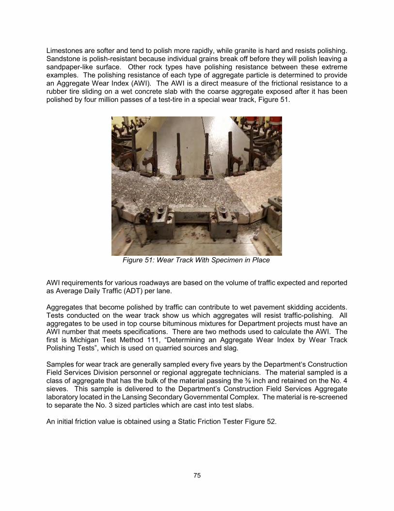
75
Limestones are softer and tend to polish more rapidly, while granite is hard and resists polishing. Sandstone is polish-resistant because individual grains break off before they will polish leaving a sandpaper-like surface. Other rock types have polishing resistance between these extreme examples. The polishing resistance of each type of aggregate particle is determined to provide an Aggregate Wear Index (AWI). The AWI is a direct measure of the frictional resistance to a rubber tire sliding on a wet concrete slab with the coarse aggregate exposed after it has been polished by four million passes of a test-tire in a special wear track, Figure 51.
Figure 51: Wear Track With Specimen in Place
AWI requirements for various roadways are based on the volume of traffic expected and reported as Average Daily Traffic (ADT) per lane. Aggregates that become polished by traffic can contribute to wet pavement skidding accidents. Tests conducted on the wear track show us which aggregates will resist traffic-polishing. All aggregates to be used in top course bituminous mixtures for Department projects must have an AWI number that meets specifications. There are two methods used to calculate the AWI. The first is Michigan Test Method 111, “Determining an Aggregate Wear Index by Wear Track Polishing Tests”, which is used on quarried sources and slag. Samples for wear track are generally sampled every five years by the Department‘s Construction Field Services Division personnel or regional aggregate technicians. The material sampled is a class of aggregate that has the bulk of the material passing the ⅜ inch and retained on the No. 4 sieves. This sample is delivered to the Department’s Construction Field Services Aggregate laboratory located in the Lansing Secondary Governmental Complex. The material is re-screened to separate the No. 3 sized particles which are cast into test slabs. An initial friction value is obtained using a Static Friction Tester Figure 52.
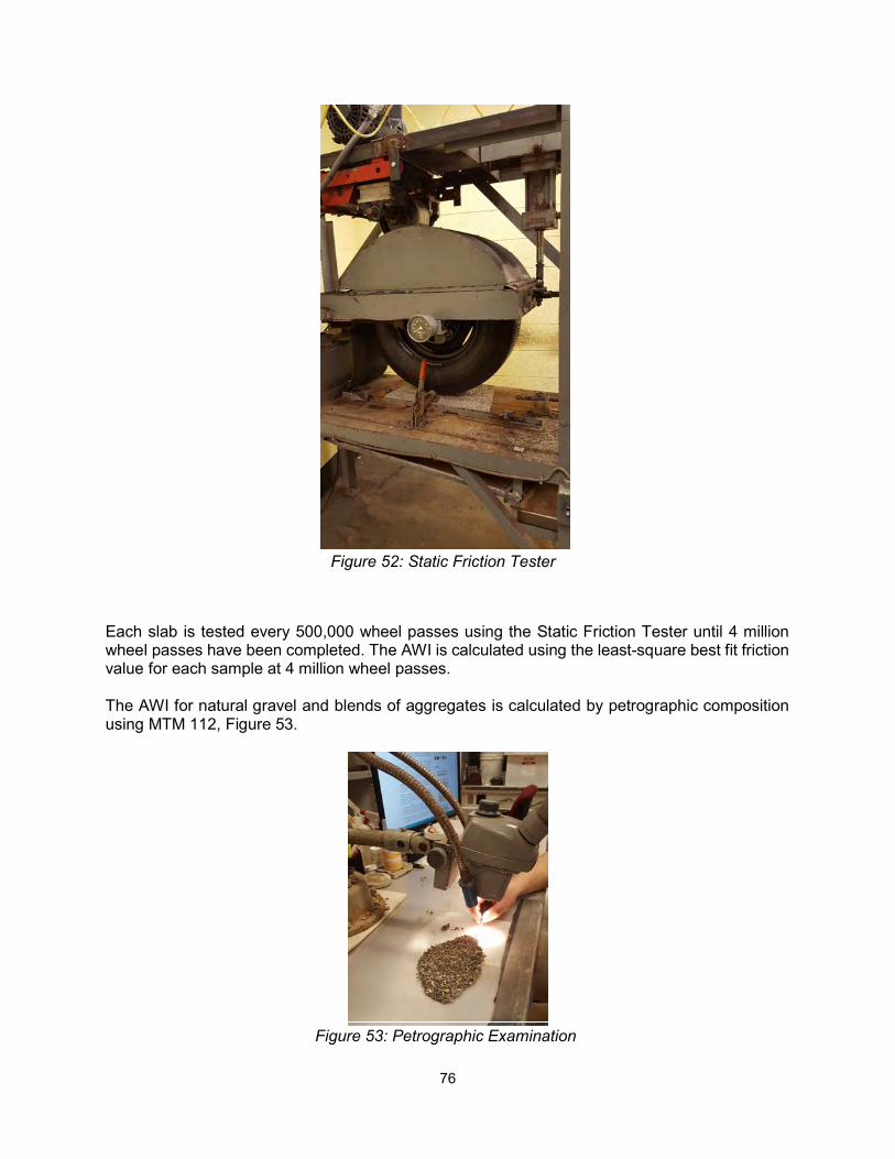
76
Each slab is tested every 500,000 wheel passes using the Static Friction Tester until 4 million wheel passes have been completed. The AWI is calculated using the least-square best fit friction value for each sample at 4 million wheel passes. The AWI for natural gravel and blends of aggregates is calculated by petrographic composition using MTM 112, Figure 53.
Figure 53: Petrographic Examination
Figure 52: Static Friction Tester
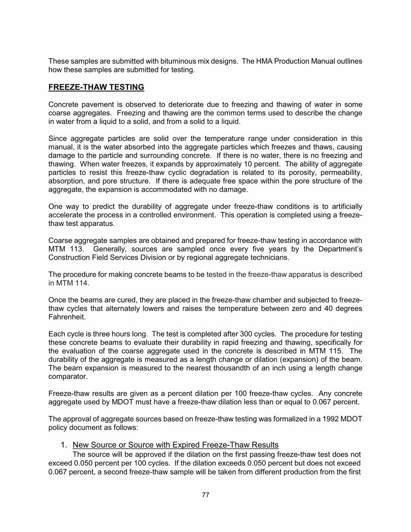
77
These samples are submitted with bituminous mix designs. The HMA Production Manual outlines how these samples are submitted for testing. FREEZE-THAW TESTING Concrete pavement is observed to deteriorate due to freezing and thawing of water in some coarse aggregates. Freezing and thawing are the common terms used to describe the change in water from a liquid to a solid, and from a solid to a liquid. Since aggregate particles are solid over the temperature range under consideration in this manual, it is the water absorbed into the aggregate particles which freezes and thaws, causing damage to the particle and surrounding concrete. If there is no water, there is no freezing and thawing. When water freezes, it expands by approximately 10 percent. The ability of aggregate particles to resist this freeze-thaw cyclic degradation is related to its porosity, permeability, absorption, and pore structure. If there is adequate free space within the pore structure of the aggregate, the expansion is accommodated with no damage. One way to predict the durability of aggregate under freeze-thaw conditions is to artificially accelerate the process in a controlled environment. This operation is completed using a freeze-thaw test apparatus. Coarse aggregate samples are obtained and prepared for freeze-thaw testing in accordance with MTM 113. Generally, sources are sampled once every five years by the Department’s Construction Field Services Division or by regional aggregate technicians. The procedure for making concrete beams to be tested in the freeze-thaw apparatus is described in MTM 114. Once the beams are cured, they are placed in the freeze-thaw chamber and subjected to freeze-thaw cycles that alternately lowers and raises the temperature between zero and 40 degrees Fahrenheit. Each cycle is three hours long. The test is completed after 300 cycles. The procedure for testing these concrete beams to evaluate their durability in rapid freezing and thawing, specifically for the evaluation of the coarse aggregate used in the concrete is described in MTM 115. The durability of the aggregate is measured as a length change or dilation (expansion) of the beam. The beam expansion is measured to the nearest thousandth of an inch using a length change comparator. Freeze-thaw results are given as a percent dilation per 100 freeze-thaw cycles. Any concrete aggregate used by MDOT must have a freeze-thaw dilation less than or equal to 0.067 percent. The approval of aggregate sources based on freeze-thaw testing was formalized in a 1992 MDOT policy document as follows:
1. New Source or Source with Expired Freeze-Thaw Results The source will be approved if the dilation on the first passing freeze-thaw test does not
exceed 0.050 percent per 100 cycles. If the dilation exceeds 0.050 percent but does not exceed 0.067 percent, a second freeze-thaw sample will be taken from different production from the first
78
sample. The source will be approved if the second freeze-thaw does not exceed 0.067 percent per 100 cycles. The effective date is the date on the certified letter notifying the producer.
If the first or second freeze-thaw samples, taken from a new source or a source with an expired freeze-thaw results, have a dilation test result exceeding the 0.067 percent specification limit, the source will not be approved. Freeze-thaw results on a source will expire five years after notification to the producer of the most recent freeze-thaw test results.
2. Currently Approved Source
A. Meets Specification
When a subsequent freeze-thaw test results in a dilation less than or equal to the MDOT’ s basic specification or specific use requirement, the freeze-thaw result will be effective as of the date on the certified letter notifying the producer.
B. Does Not Meet Specification
When a subsequent freeze-thaw test results in a dilation greater than MDOT’s basic specification requirement, or specification limit for specific use, the effective date of the new result will be the date of the receipt of the letter sent by certified mail to the producer.
1. Disapproval of a Source- For those sources where there has been no change in the aggregate characteristics, when a freeze-thaw test results in a dilation greater than 0.120 percent per 100 cycles, or the average of the current sample and previous regular freeze-thaw sample is greater than 0.080 percent, the source will be disapproved. All shipments to MDOT projects must stop within 24 hrs of receipt of the certified letter notifying the producer. Stocks of aggregate at a contractor’s plant may be authorized by the engineer for use until satisfactory material can be obtained, but under no condition will this authorization exceed 14 calendar days.
2. Extension of Previous Test Result – For freeze-thaw test results failing to meet he basic specification requirement but not covered by B.1. above, the producer must, within 14 calendar days from date of receipt of the certified letter of notification, make arrangements with MDOT’s Materials section, for submitting a new freeze-thaw sample. The retest sample will be obtained and submitted to the Aggregate Quality Lab within 30 days of receipt of the certified letter. If a new freeze-thaw test sample is not received within this 30 calendar day period because the producer was unable to supply aggregate for MDOT to sample, material will no longer be accepted for use on department projects unless an extension is granted by MDOT.
Upon receipt of a freeze-thaw retest sample, MDOT will extend the results of the previous acceptable freeze-thaw test until the retest is completed, provided the aggregate can be produced to acceptable quality as determined on a case by case basis as stated in the chart to follow. New orders will be allowed to be bid during this retest period, contingent on these conditions and the following retest requirements.
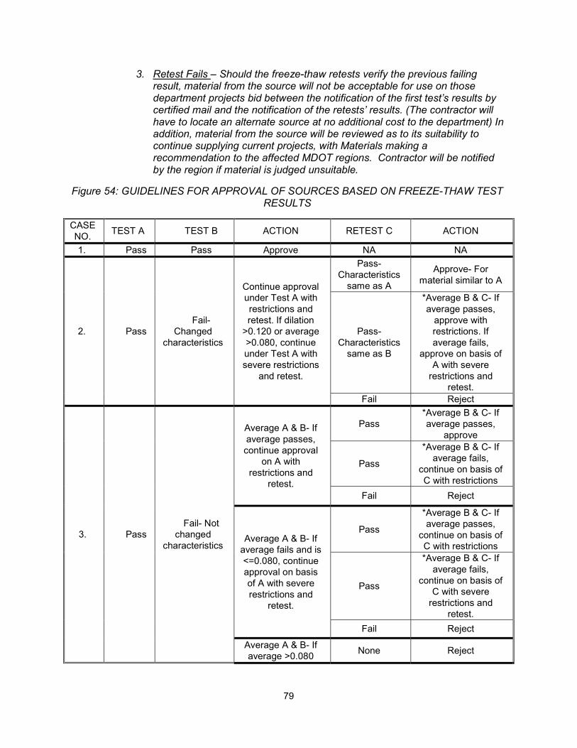
79
3. Retest Fails – Should the freeze-thaw retests verify the previous failing result, material from the source will not be acceptable for use on those department projects bid between the notification of the first test’s results by certified mail and the notification of the retests’ results. (The contractor will have to locate an alternate source at no additional cost to the department) In addition, material from the source will be reviewed as to its suitability to continue supplying current projects, with Materials making a recommendation to the affected MDOT regions. Contractor will be notified by the region if material is judged unsuitable.
Figure 54: GUIDELINES FOR APPROVAL OF SOURCES BASED ON FREEZE-THAW TEST RESULTS
CASE NO.
TEST A TEST B ACTION RETEST C ACTION
1. Pass Pass Approve NA NA
2. Pass Fail-
Changed characteristics
Continue approval under Test A with restrictions and retest. If dilation
>0.120 or average >0.080, continue under Test A with severe restrictions
and retest.
Pass- Characteristics
same as A
Approve- For material similar to A
Pass- Characteristics
same as B
*Average B & C- If average passes,
approve with restrictions. If average fails,
approve on basis of A with severe
restrictions and retest.
Fail Reject
3. Pass Fail- Not
changed characteristics
Average A & B- If average passes,
continue approval on A with
restrictions and retest.
Pass *Average B & C- If average passes,
approve
Pass
*Average B & C- If average fails,
continue on basis of C with restrictions
Fail Reject
Average A & B- If average fails and is <=0.080, continue approval on basis of A with severe restrictions and
retest.
Pass
*Average B & C- If average passes,
continue on basis of C with restrictions
Pass
*Average B & C- If average fails,
continue on basis of C with severe
restrictions and retest.
Fail Reject
Average A & B- If average >0.080
None Reject
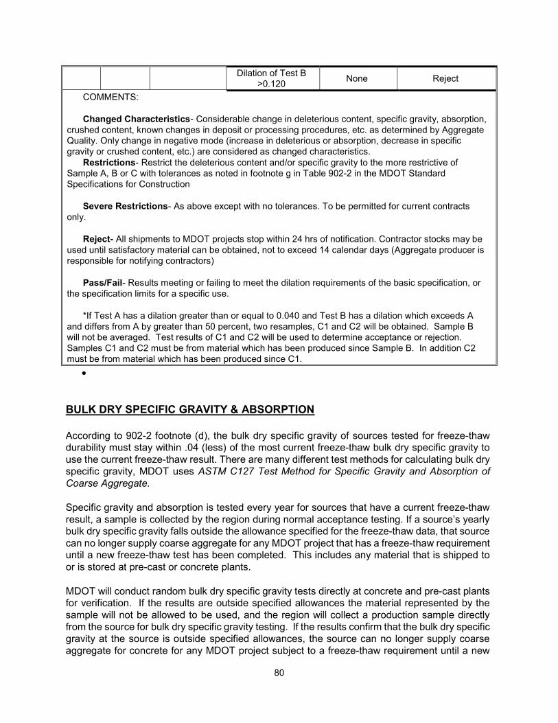
80
Dilation of Test B >0.120
None Reject
COMMENTS: Changed Characteristics- Considerable change in deleterious content, specific gravity, absorption,
crushed content, known changes in deposit or processing procedures, etc. as determined by Aggregate Quality. Only change in negative mode (increase in deleterious or absorption, decrease in specific gravity or crushed content, etc.) are considered as changed characteristics.
Restrictions- Restrict the deleterious content and/or specific gravity to the more restrictive of Sample A, B or C with tolerances as noted in footnote g in Table 902-2 in the MDOT Standard Specifications for Construction
Severe Restrictions- As above except with no tolerances. To be permitted for current contracts
only. Reject- All shipments to MDOT projects stop within 24 hrs of notification. Contractor stocks may be
used until satisfactory material can be obtained, not to exceed 14 calendar days (Aggregate producer is responsible for notifying contractors)
Pass/Fail- Results meeting or failing to meet the dilation requirements of the basic specification, or
the specification limits for a specific use. *If Test A has a dilation greater than or equal to 0.040 and Test B has a dilation which exceeds A
and differs from A by greater than 50 percent, two resamples, C1 and C2 will be obtained. Sample B will not be averaged. Test results of C1 and C2 will be used to determine acceptance or rejection. Samples C1 and C2 must be from material which has been produced since Sample B. In addition C2 must be from material which has been produced since C1.
BULK DRY SPECIFIC GRAVITY & ABSORPTION According to 902-2 footnote (d), the bulk dry specific gravity of sources tested for freeze-thaw durability must stay within .04 (less) of the most current freeze-thaw bulk dry specific gravity to use the current freeze-thaw result. There are many different test methods for calculating bulk dry specific gravity, MDOT uses ASTM C127 Test Method for Specific Gravity and Absorption of Coarse Aggregate. Specific gravity and absorption is tested every year for sources that have a current freeze-thaw result, a sample is collected by the region during normal acceptance testing. If a source’s yearly bulk dry specific gravity falls outside the allowance specified for the freeze-thaw data, that source can no longer supply coarse aggregate for any MDOT project that has a freeze-thaw requirement until a new freeze-thaw test has been completed. This includes any material that is shipped to or is stored at pre-cast or concrete plants. MDOT will conduct random bulk dry specific gravity tests directly at concrete and pre-cast plants for verification. If the results are outside specified allowances the material represented by the sample will not be allowed to be used, and the region will collect a production sample directly from the source for bulk dry specific gravity testing. If the results confirm that the bulk dry specific gravity at the source is outside specified allowances, the source can no longer supply coarse aggregate for concrete for any MDOT project subject to a freeze-thaw requirement until a new
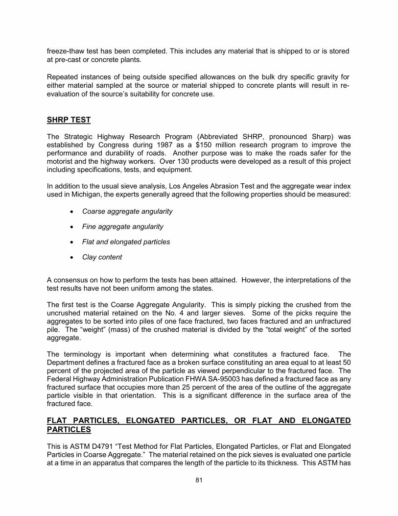
81
freeze-thaw test has been completed. This includes any material that is shipped to or is stored at pre-cast or concrete plants. Repeated instances of being outside specified allowances on the bulk dry specific gravity for either material sampled at the source or material shipped to concrete plants will result in re-evaluation of the source’s suitability for concrete use. SHRP TEST The Strategic Highway Research Program (Abbreviated SHRP, pronounced Sharp) was established by Congress during 1987 as a $150 million research program to improve the performance and durability of roads. Another purpose was to make the roads safer for the motorist and the highway workers. Over 130 products were developed as a result of this project including specifications, tests, and equipment. In addition to the usual sieve analysis, Los Angeles Abrasion Test and the aggregate wear index used in Michigan, the experts generally agreed that the following properties should be measured:
Coarse aggregate angularity
Fine aggregate angularity
Flat and elongated particles
Clay content
A consensus on how to perform the tests has been attained. However, the interpretations of the test results have not been uniform among the states. The first test is the Coarse Aggregate Angularity. This is simply picking the crushed from the uncrushed material retained on the No. 4 and larger sieves. Some of the picks require the aggregates to be sorted into piles of one face fractured, two faces fractured and an unfractured pile. The “weight” (mass) of the crushed material is divided by the “total weight” of the sorted aggregate. The terminology is important when determining what constitutes a fractured face. The Department defines a fractured face as a broken surface constituting an area equal to at least 50 percent of the projected area of the particle as viewed perpendicular to the fractured face. The Federal Highway Administration Publication FHWA SA-95003 has defined a fractured face as any fractured surface that occupies more than 25 percent of the area of the outline of the aggregate particle visible in that orientation. This is a significant difference in the surface area of the fractured face. FLAT PARTICLES, ELONGATED PARTICLES, OR FLAT AND ELONGATED PARTICLES This is ASTM D4791 “Test Method for Flat Particles, Elongated Particles, or Flat and Elongated Particles in Coarse Aggregate.” The material retained on the pick sieves is evaluated one particle at a time in an apparatus that compares the length of the particle to its thickness. This ASTM has
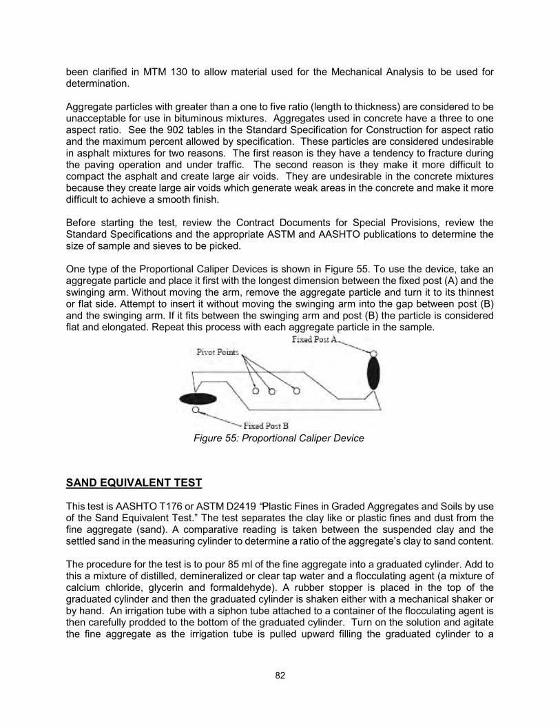
82
been clarified in MTM 130 to allow material used for the Mechanical Analysis to be used for determination. Aggregate particles with greater than a one to five ratio (length to thickness) are considered to be unacceptable for use in bituminous mixtures. Aggregates used in concrete have a three to one aspect ratio. See the 902 tables in the Standard Specification for Construction for aspect ratio and the maximum percent allowed by specification. These particles are considered undesirable in asphalt mixtures for two reasons. The first reason is they have a tendency to fracture during the paving operation and under traffic. The second reason is they make it more difficult to compact the asphalt and create large air voids. They are undesirable in the concrete mixtures because they create large air voids which generate weak areas in the concrete and make it more difficult to achieve a smooth finish. Before starting the test, review the Contract Documents for Special Provisions, review the Standard Specifications and the appropriate ASTM and AASHTO publications to determine the size of sample and sieves to be picked. One type of the Proportional Caliper Devices is shown in Figure 55. To use the device, take an aggregate particle and place it first with the longest dimension between the fixed post (A) and the swinging arm. Without moving the arm, remove the aggregate particle and turn it to its thinnest or flat side. Attempt to insert it without moving the swinging arm into the gap between post (B) and the swinging arm. If it fits between the swinging arm and post (B) the particle is considered flat and elongated. Repeat this process with each aggregate particle in the sample.
Figure 55: Proportional Caliper Device
SAND EQUIVALENT TEST This test is AASHTO T176 or ASTM D2419 “Plastic Fines in Graded Aggregates and Soils by use of the Sand Equivalent Test.” The test separates the clay like or plastic fines and dust from the fine aggregate (sand). A comparative reading is taken between the suspended clay and the settled sand in the measuring cylinder to determine a ratio of the aggregate’s clay to sand content. The procedure for the test is to pour 85 ml of the fine aggregate into a graduated cylinder. Add to this a mixture of distilled, demineralized or clear tap water and a flocculating agent (a mixture of calcium chloride, glycerin and formaldehyde). A rubber stopper is placed in the top of the graduated cylinder and then the graduated cylinder is shaken either with a mechanical shaker or by hand. An irrigation tube with a siphon tube attached to a container of the flocculating agent is then carefully prodded to the bottom of the graduated cylinder. Turn on the solution and agitate the fine aggregate as the irrigation tube is pulled upward filling the graduated cylinder to a
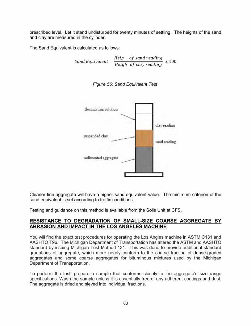
83
prescribed level. Let it stand undisturbed for twenty minutes of settling. The heights of the sand and clay are measured in the cylinder. The Sand Equivalent is calculated as follows:
ℎ 100
Figure 56: Sand Equivalent Test
Cleaner fine aggregate will have a higher sand equivalent value. The minimum criterion of the sand equivalent is set according to traffic conditions. Testing and guidance on this method is available from the Soils Unit at CFS. RESISTANCE TO DEGRADATION OF SMALL-SIZE COARSE AGGREGATE BY ABRASION AND IMPACT IN THE LOS ANGELES MACHINE You will find the exact test procedures for operating the Los Angles machine in ASTM C131 and AASHTO T96. The Michigan Department of Transportation has altered the ASTM and AASHTO standard by issuing Michigan Test Method 131. This was done to provide additional standard gradations of aggregate, which more nearly conform to the coarse fraction of dense-graded aggregates and some coarse aggregates for bituminous mixtures used by the Michigan Department of Transportation. To perform the test, prepare a sample that conforms closely to the aggregate’s size range specifications. Wash the sample unless it is essentially free of any adherent coatings and dust. The aggregate is dried and sieved into individual fractions.
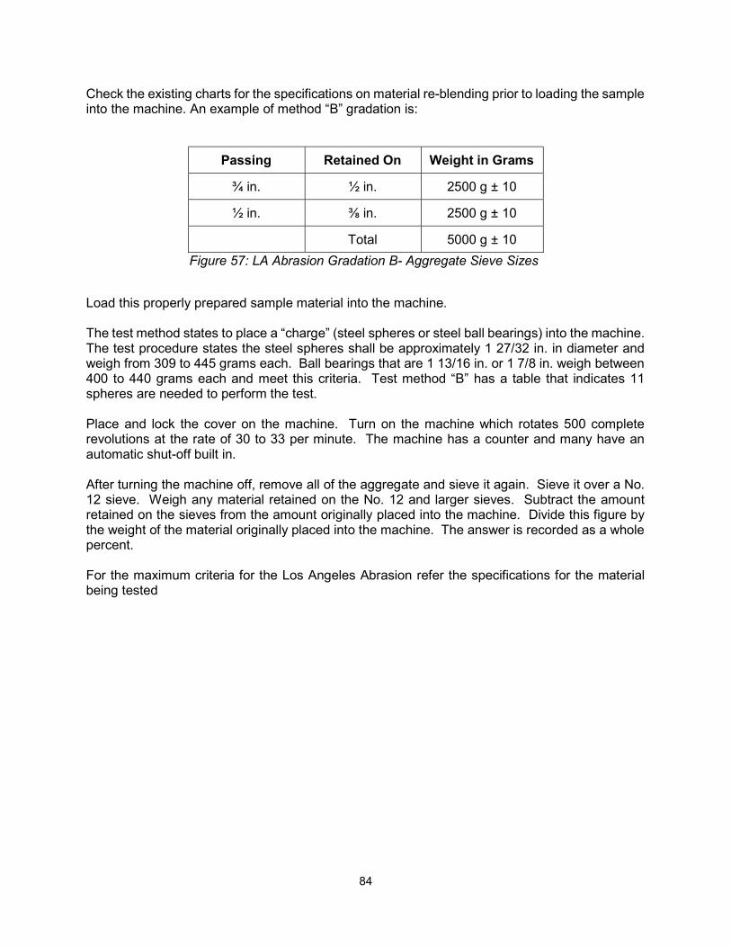
84
Check the existing charts for the specifications on material re-blending prior to loading the sample into the machine. An example of method “B” gradation is:
Passing Retained On Weight in Grams
¾ in. ½ in. 2500 g ± 10
½ in. ⅜ in. 2500 g ± 10
Total 5000 g ± 10
Figure 57: LA Abrasion Gradation B- Aggregate Sieve Sizes
Load this properly prepared sample material into the machine. The test method states to place a “charge” (steel spheres or steel ball bearings) into the machine. The test procedure states the steel spheres shall be approximately 1 27/32 in. in diameter and weigh from 309 to 445 grams each. Ball bearings that are 1 13/16 in. or 1 7/8 in. weigh between 400 to 440 grams each and meet this criteria. Test method “B” has a table that indicates 11 spheres are needed to perform the test. Place and lock the cover on the machine. Turn on the machine which rotates 500 complete revolutions at the rate of 30 to 33 per minute. The machine has a counter and many have an automatic shut-off built in. After turning the machine off, remove all of the aggregate and sieve it again. Sieve it over a No. 12 sieve. Weigh any material retained on the No. 12 and larger sieves. Subtract the amount retained on the sieves from the amount originally placed into the machine. Divide this figure by the weight of the material originally placed into the machine. The answer is recorded as a whole percent. For the maximum criteria for the Los Angeles Abrasion refer the specifications for the material being tested
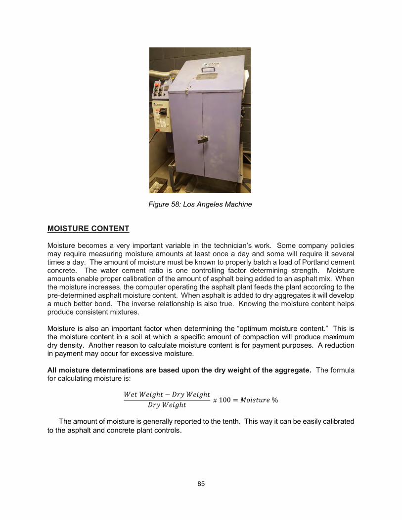
85
Figure 58: Los Angeles Machine
MOISTURE CONTENT Moisture becomes a very important variable in the technician’s work. Some company policies may require measuring moisture amounts at least once a day and some will require it several times a day. The amount of moisture must be known to properly batch a load of Portland cement concrete. The water cement ratio is one controlling factor determining strength. Moisture amounts enable proper calibration of the amount of asphalt being added to an asphalt mix. When the moisture increases, the computer operating the asphalt plant feeds the plant according to the pre-determined asphalt moisture content. When asphalt is added to dry aggregates it will develop a much better bond. The inverse relationship is also true. Knowing the moisture content helps produce consistent mixtures. Moisture is also an important factor when determining the “optimum moisture content.” This is the moisture content in a soil at which a specific amount of compaction will produce maximum dry density. Another reason to calculate moisture content is for payment purposes. A reduction in payment may occur for excessive moisture. All moisture determinations are based upon the dry weight of the aggregate. The formula for calculating moisture is:
ℎ − ℎ ℎ
100 = %
The amount of moisture is generally reported to the tenth. This way it can be easily calibrated
to the asphalt and concrete plant controls.

86
87
REFERENCES
1. American Association of State Highway and Transportation Officials, 444 North Capital
Street NW, Suite 225, Washington D.C. 20001.
2. American Society for Testing and Materials, 100 Barr Harbor Drive, PO Box C700, West
Conshohocken, PA 19428-2959. Telephone: 610.832.9585 Website: www.astm.org
3. Michigan Test Methods, available from Michigan Department of Transportation,
Financial Operations Division, Cashiers Office, P.O. Box 30050, Lansing, MI 48909.
4. Michigan Department of Transportation’s Website: http://www.mdot.state.mi.us/contractors/
5. HMA Production Manual:
http://www.michigan.gov/documents/mdot_HMA_ProductionManual_79005_7.pdf
6. Michigan Department of Transportation’s Standard Specifications for Construction